Valves & Regulators 16: Valves & Regulators www.EMIcorp.com EOAT Design and Build Service From the simplest to the most complex EOAT, EMI specializes in designing and building customized End-of-Arm-Tooling— Priced Competitively . Get started by sending us a sample part or 3D part file and a completed datasheet (see page 972). Our EOAT engineers will design a tool for you and provide you 3D CAD renderings. We’ll also provide pricing for the tool should you want to purchase the completely assembled EOAT from EMI. Whether or not you purchase the tool from EMI, there’s no cost or obligation to you for the engineering design service. ® 908

Welcome message from author
This document is posted to help you gain knowledge. Please leave a comment to let me know what you think about it! Share it to your friends and learn new things together.
Transcript
Valves & Regulators
16: Valves & Regulators
www.EMI corp.com
EOAT Design and Build Service
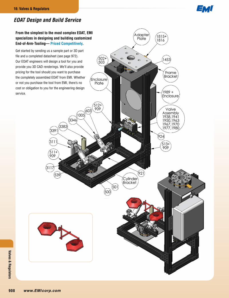
From the simplest to the most complex EOAT, EMI specializes in designing and building customized End-of-Arm-Tooling— Priced Competitively.
Get started by sending us a sample part or 3D part
file and a completed datasheet (see page 972).
Our EOAT engineers will design a tool for you and
provide you 3D CAD renderings. We’ll also provide
pricing for the tool should you want to purchase
the completely assembled EOAT from EMI. Whether
or not you purchase the tool from EMI, there’s no
cost or obligation to you for the engineering design
service.
®
908

Valv
es &
Reg
ulat
ors
16: Valves & Regulators
216-535-4848
Mini Pressure Regulators Flow (Speed) Control Exhaust Valves
Inline Filters Vacuum Generators Vacuum Generators
Modular Valves
Lightweight and modular, these
valves are ideally suited for
mounting on robotic EOAT. Use
to control grippers, cylinders, and
vacuum circuits.
Valves & Regulators Overview
p.910
p.911
p.911
p.912
p.911
p.915
p.914
Mini Pressure Regulators p.910
Pressure regulators meter and maintain output pressure to
pneumatic devices despite power supply pressure fluctuations
and help control pressure for pressure sensitive applications.
®
909
#1470
#1468
2491
30.5
17.5
Ø3.3(2X)
4
4
66.6
(2X) 6mm PORTS
53.3
Ø3.3(2X)
21
8.5
1015
Valves & Regulators
16: Valves & Regulators
www.EMI corp.com
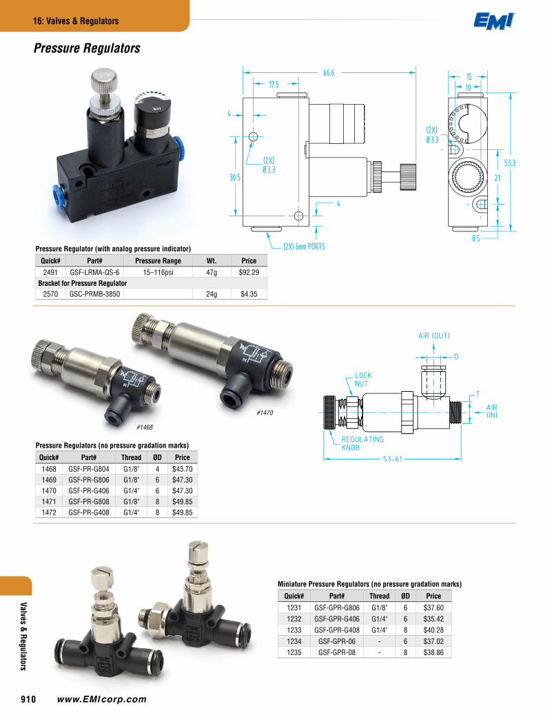
Pressure Regulators (no pressure gradation marks)
Quick# Part# Thread ØD Price
1468 GSF-PR-G804 G1/8" 4 $43.701469 GSF-PR-G806 G1/8" 6 $47.301470 GSF-PR-G406 G1/4" 6 $47.301471 GSF-PR-G808 G1/8" 8 $49.851472 GSF-PR-G408 G1/4" 8 $49.85
Pressure Regulator (with analog pressure indicator)
Quick# Part# Pressure Range Wt. Price
2491 GSF-LRMA-QS-6 15–116psi 47g $92.29Bracket for Pressure Regulator
2570 GSC-PRMB-3850 24g $4.35
Pressure Regulators
Miniature Pressure Regulators (no pressure gradation marks)
Quick# Part# Thread ØD Price
1231 GSF-GPR-G806 G1/8" 6 $37.601232 GSF-GPR-G406 G1/4" 6 $35.421233 GSF-GPR-G408 G1/4" 8 $40.281234 GSF-GPR-06 - 6 $37.021235 GSF-GPR-08 - 8 $38.86
®
910

#1853
#2645
#1852
Valv
es &
Reg
ulat
ors
16: Valves & Regulators
216-535-4848
Exhaust Valve & Silencer
Quick# Part# Tubing ØD Dimensions Price
1852 GSF-EQE-4 4 30mm Tall, 34.5mm Long, 10mm Wide $15.731853 GSF-EQE-6 6 32.8mm Tall, 37mm Long, 12mm Wide $16.18
Flow (Speed) Control
Quick# Part# Thread ØD Control Price
297 GSF-FCI-04 - 4 In-Line $23.60298 GSF-FCI-06 - 6 In-Line $31.25299 GSF-FCI-08 - 8 In-Line $33.20373 GSF-FCE-M304 M3 4 Exhaust $12.45300 GSF-FCE-M504 M5 4 Exhaust $11.70301 GSF-FCE-M506 M5 6 Exhaust $14.90302 GSF-FCE-G806 G1/8" 6 Exhaust $14.90374 GSF-FCS-M304 M3 4 Supply $12.45303 GSF-FCS-M504 M5 4 Supply $11.70304 GSF-FCS-M506 M5 6 Supply $14.90305 GSF-FCS-G806 G1/8" 6 Supply $13.80306 GSF-FCB-M504 M5 4 Bi-Directional $11.30307 GSF-FCB-M506 M5 6 Bi-Directional $14.35308 GSF-FCB-G806 G1/8" 6 Bi-Directional $13.80
Flow Control
#300Exhaust Control
#304Supply Control
(#306-308 is same body style as #300-305)
Internal Exhaust Silencer
#298In-Line Control
Positive & Negative Pressure Filters
Quick# Part# ØD Size Filter Area Price
2644 GSF-SFU2-0404 4 SFU2 0.72 Inch² $16.912645 GSF-SFU2-0606 6 SFU2 1.16 Inch² $17.092646 GSF-SFU3-0808 8 SFU3 1.96 Inch² $18.73
Replacement Elements
Quick# Part# ØD Size Filter Area Price
2647 GSF-SFE-2 - SFU2 1.16 Inch² $2.732648 GSF-SFE-3 - SFU3 1.96 Inch² $3.18
Internal Exhaust Silencer
INOUT INOUT
• New, improved filters
• Replacement elements are not compatible with older versions.
®
911
A B C D F G H J K L
361 51 20 10 M5 M5 3.5 10 8 3.5 M5x6362 97 26 16 G1/8 G1/8 3.5 15 16 5 -363 121 38 22 G1/4 G1/4 4.5 21 20 5 -
362
361
362
363
A B C D F G H J K L WT51 20 10 M5 M5 3.5 10 8 3.5 M5X6 11
97 26 16 G1/8 G1/8 3.5 15 16 5 - 50
121 38 22 G1/4 G1/4 4.5 21 20 5 - 110
G
JH K
AF VACUUM
L MOUNTING HOLEC
B
D AIR PORTValves &
Regulators
16: Valves & Regulators
www.EMI corp.com
3.5mm slot for M3 fasteners
3.5mm slot for M3 fasteners
4.5mm slot for M4 fasteners
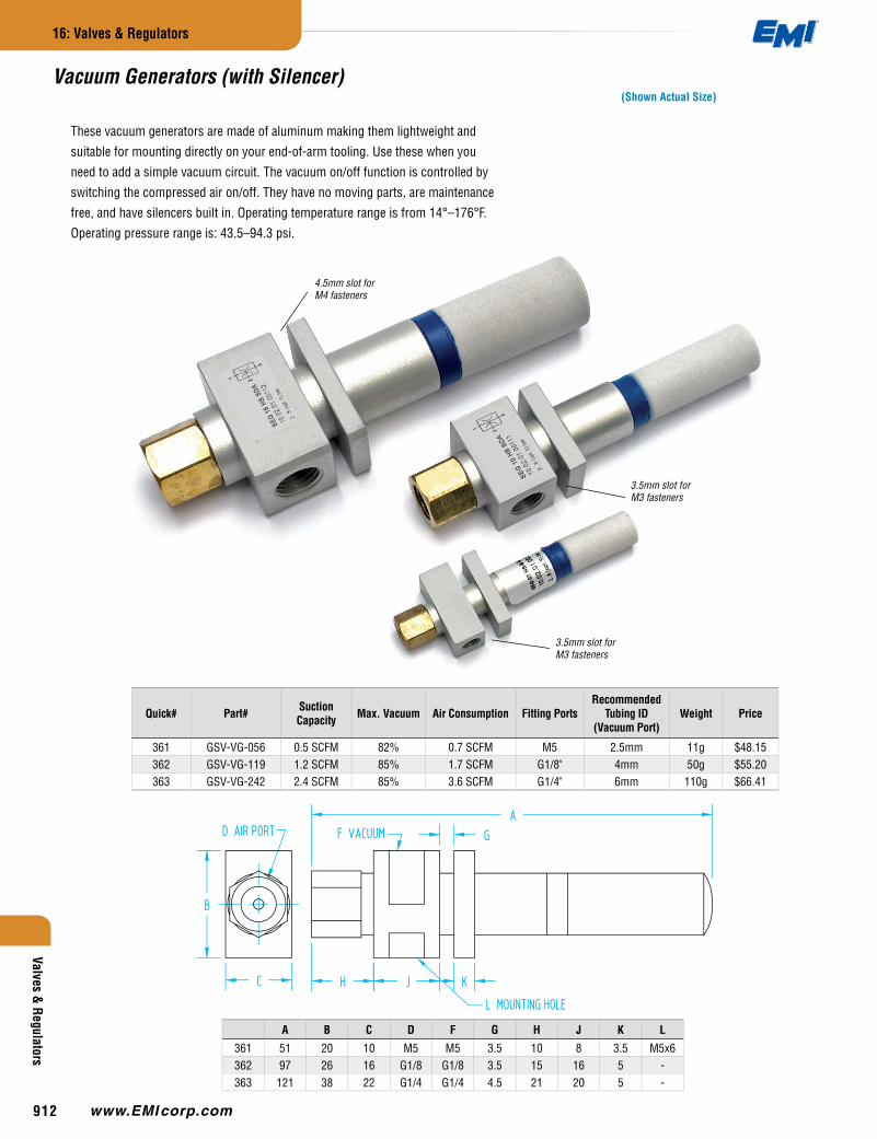
Quick# Part# Suction Capacity Max. Vacuum Air Consumption Fitting Ports
Recommended Tubing ID
(Vacuum Port)Weight Price
361 GSV-VG-056 0.5 SCFM 82% 0.7 SCFM M5 2.5mm 11g $48.15362 GSV-VG-119 1.2 SCFM 85% 1.7 SCFM G1/8" 4mm 50g $55.20363 GSV-VG-242 2.4 SCFM 85% 3.6 SCFM G1/4" 6mm 110g $66.41
These vacuum generators are made of aluminum making them lightweight and
suitable for mounting directly on your end-of-arm tooling. Use these when you
need to add a simple vacuum circuit. The vacuum on/off function is controlled by
switching the compressed air on/off. They have no moving parts, are maintenance
free, and have silencers built in. Operating temperature range is from 14°–176°F.
Operating pressure range is: 43.5–94.3 psi.
(Shown Actual Size)Vacuum Generators (with Silencer)
®
912
A B C D F G H J K
2033 74 31 10 M5 M5 4.2 17.5 20 5.22034 102 42 15 G1/8 G1/8 4.2 22.5 20 5.22035 102 42 15 G1/8 G1/8 4.2 22.5 20 5.2
QUICK #2034 SHOWN
A B C D F G H J K2033 74 31 10 M5 M5 4.2 17.5 20 5.22034 102 42 15 G1/8 G1/8 4.2 22.5 20 5.22035 102 42 15 G1/8 G1/8 4.2 22.5 20 5.2
A
JH G MOUNTING HOLE
K
F VACUUM PORT
B
C
D AIR PORTVa
lves
& R
egul
ator
s
16: Valves & Regulators
216-535-4848
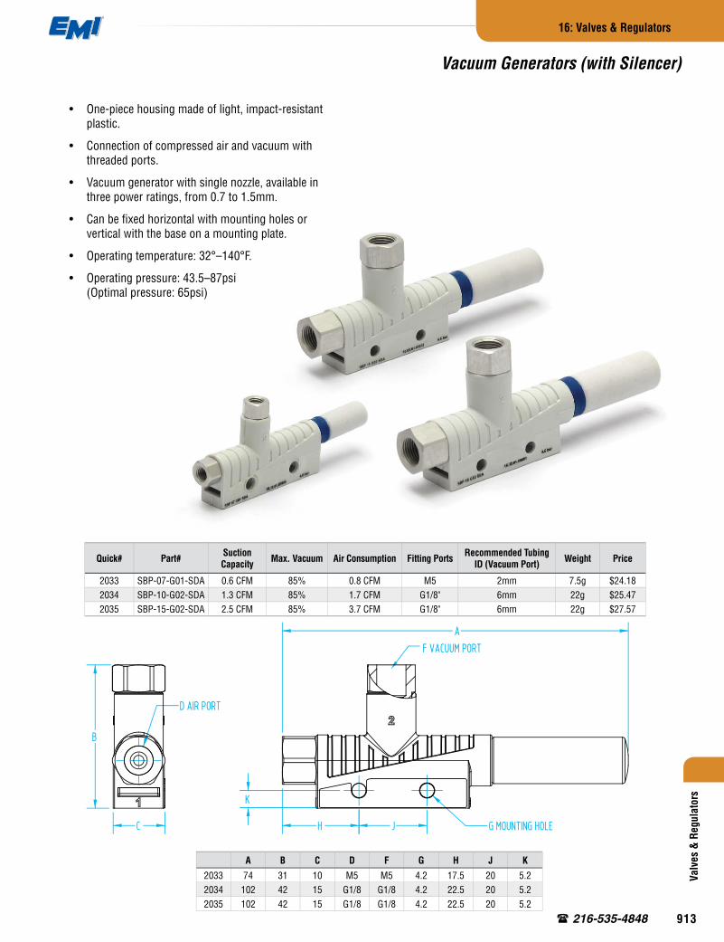
Vacuum Generators (with Silencer)
Quick# Part# Suction Capacity Max. Vacuum Air Consumption Fitting Ports Recommended Tubing
ID (Vacuum Port) Weight Price
2033 SBP-07-G01-SDA 0.6 CFM 85% 0.8 CFM M5 2mm 7.5g $24.182034 SBP-10-G02-SDA 1.3 CFM 85% 1.7 CFM G1/8" 6mm 22g $25.472035 SBP-15-G02-SDA 2.5 CFM 85% 3.7 CFM G1/8" 6mm 22g $27.57
• One-piece housing made of light, impact-resistant plastic.
• Connection of compressed air and vacuum with threaded ports.
• Vacuum generator with single nozzle, available in three power ratings, from 0.7 to 1.5mm.
• Can be fixed horizontal with mounting holes or vertical with the base on a mounting plate.
• Operating temperature: 32°–140°F.
• Operating pressure: 43.5–87psi (Optimal pressure: 65psi)
®
913
#5235 & #5236
#5237 & #5238
#2051
#2050 & #2052
Valves & Regulators
16: Valves & Regulators
www.EMI corp.com
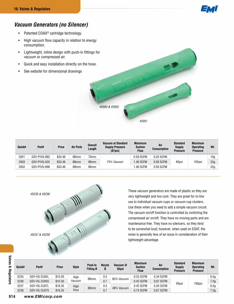
These vacuum generators are made of plastic so they are
very lightweight and low cost. They are great for in-line
use to individual vacuum cups or vacuum cup clusters.
Use these when you need to add a simple vacuum circuit.
The vacuum on/off function is controlled by switching the
compressed air on/off. They have no moving parts and are
maintenance free. They have no silencers, so they tend
to be somewhat loud; however, when used on EOAT, the
noise is generally less of an issue in consideration of their
lightweight advantage.
Quick# Part# Price Style Push-In Fitting Ø
Nozzle Ø
Vacuum @ 65psi
Maximum Suction
Flow
Air Consumption
Standard Supply
Pressure
Maximum Operating Pressure
Wt.
5235 GSV-VG-ZU05L $15.50 High Vacuum Ø6mm
0.585% Vacuum
0.25 SCFM 0.34 SCFM
65psi 100psi
6.5g5236 GSV-VG-ZU05S $15.50 0.7 0.42 SCFM 0.67 SCFM 7.0g5237 GSV-VG-ZU07L $16.35 High
Flow Ø6mm0.5
48% Vacuum0.42 SCFM 0.34 SCFM 6.5g
5238 GSV-VG-ZU07S $16.35 0.7 0.74 SCFM 0.67 SCFM 7.0g
Vacuum Generators (no Silencer)• Patented COAX® cartridge technology.
• High vacuum flow capacity in relation to energy consumption.
• Lightweight, inline design with push-in fittings for vacuum or compressed air.
• Quick and easy installation directly on the hose.
• See website for dimensional drawings
Quick# Part# Price Air Ports Overall Length
Vacuum at Standard Supply Pressure
(87psi)
Maximum Suction
Flow
Air Consumption
Standard Supply
Pressure
Maximum Operating Pressure
Wt.
2051 GSV-PIVG-882 $33.46 Ø6mm 70mm
74% Vacuum
0.59 SCFM 0.25 SCFM
65psi 102psi
10g
2050 GSV-PIVG-025 $33.46 Ø6mm 96mm 1.46 SCFM 0.93 SCFM 23g
2052 GSV-PIVG-896 $33.46 Ø8mm 96mm 1.46 SCFM 0.93 SCFM 22g
®
914
®
®
Valv
es &
Reg
ulat
ors
16: Valves & Regulators
216-535-4848
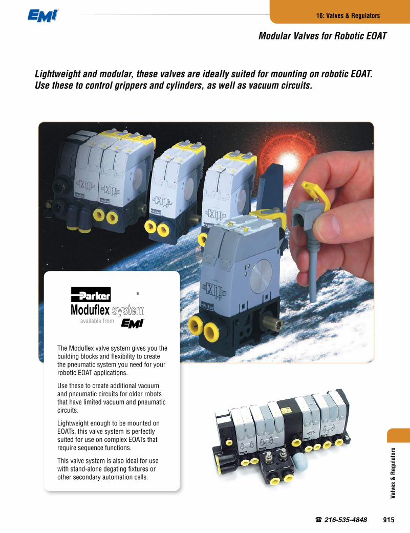
Lightweight and modular, these valves are ideally suited for mounting on robotic EOAT. Use these to control grippers and cylinders, as well as vacuum circuits.
The Moduflex valve system gives you the building blocks and flexibility to create the pneumatic system you need for your robotic EOAT applications.
Use these to create additional vacuum and pneumatic circuits for older robots that have limited vacuum and pneumatic circuits.
Lightweight enough to be mounted on EOATs, this valve system is perfectly suited for use on complex EOATs that require sequence functions.
This valve system is also ideal for use with stand-alone degating fixtures or other secondary automation cells.
Modular Valves for Robotic EOAT
available from
®
915
®
Valves & Regulators
16: Valves & Regulators
www.EMI corp.com
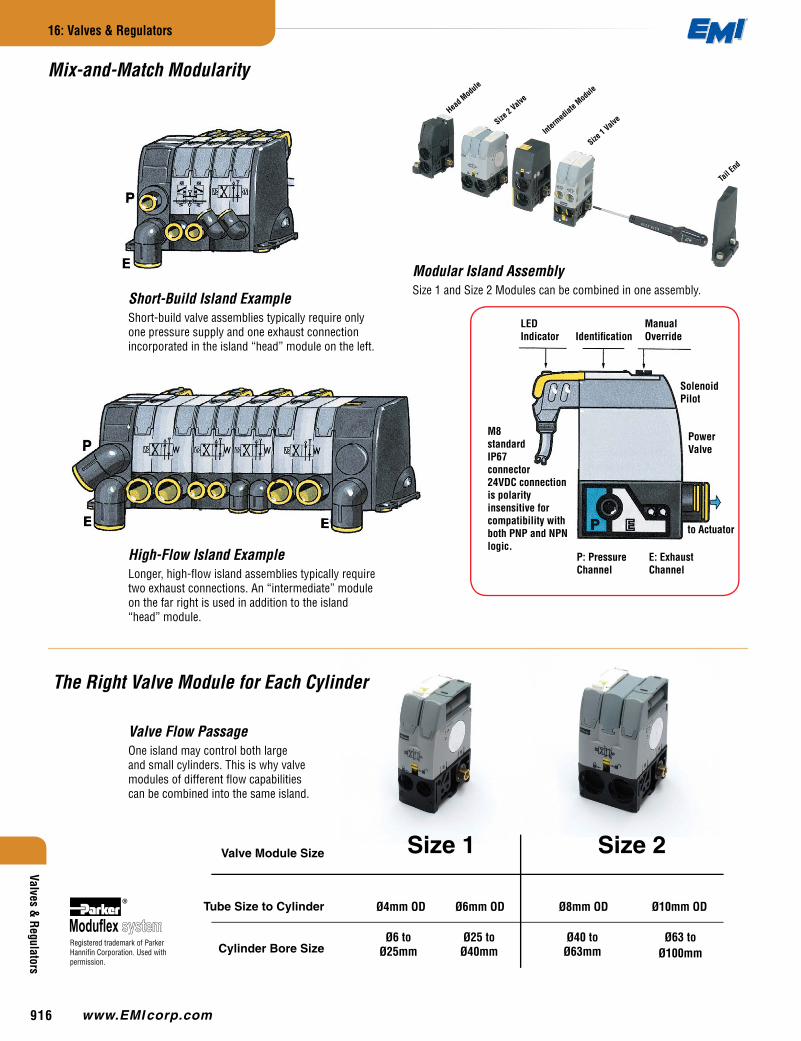
Valve Flow PassageOne island may control both large and small cylinders. This is why valve modules of different flow capabilities can be combined into the same island.
Valve Module Size
Tube Size to Cylinder
Cylinder Bore Size
Ø4mm OD Ø6mm OD Ø8mm OD Ø10mm OD
Size 1 Size 2
Ø6 to Ø25mm
Ø25 to Ø40mm
Ø40 to Ø63mm
Ø63 to Ø100mm
Modular Island Assembly Size 1 and Size 2 Modules can be combined in one assembly.
Short-Build Island ExampleShort-build valve assemblies typically require only one pressure supply and one exhaust connection incorporated in the island “head” module on the left.
High-Flow Island ExampleLonger, high-flow island assemblies typically require two exhaust connections. An “intermediate” module on the far right is used in addition to the island “head” module.
The Right Valve Module for Each Cylinder
LED Indicator Identification
Manual Override
Solenoid Pilot
Power Valve
to Actuator
P: Pressure Channel
E: Exhaust Channel
M8 standard IP67 connector 24VDC connection is polarity insensitive for compatibility with both PNP and NPN logic.
Registered trademark of Parker Hannifin Corporation. Used with permission.
Head M
odule
Size 2
Valve
Size 1
Valve
Interm
ediat
e Mod
ule
Mix-and-Match Modularity
Tail E
nd
®
916
3 1
4 2
3
1
4 2
3 1
4 2
3 1
4 2
3
1
4 2
3 1
4 2
3 1
4 2
3
1
4 2
3 1
4 2
Ø4mm OD Ø6mm OD Ø8mm OD Ø10mm OD
Valv
es &
Reg
ulat
ors
16: Valves & Regulators
216-535-4848
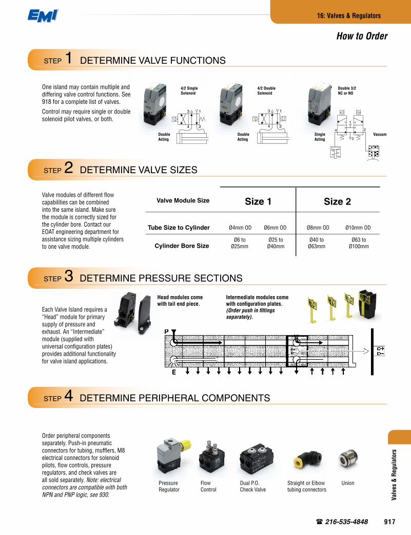
One island may contain multiple and differing valve control functions. See 918 for a complete list of valves.
Control may require single or double solenoid pilot valves, or both.
Valve modules of different flow capabilities can be combined into the same island. Make sure the module is correctly sized for the cylinder bore. Contact our EOAT engineering department for assistance sizing multiple cylinders to one valve module.
Each Valve Island requires a “Head” module for primary supply of pressure and exhaust. An “Intermediate” module (supplied with universal configuration plates) provides additional functionality for valve island applications.
Order peripheral components separately. Push-in pneumatic connectors for tubing, mufflers, M8 electrical connectors for solenoid pilots, flow controls, pressure regulators, and check valves are all sold separately. Note: electrical connectors are compatible with both NPN and PNP logic, see 930.
Head modules come with tail end piece.
Intermediate modules come with configuration plates. (Order push in fittings separately).
Valve Module Size
Tube Size to Cylinder
Cylinder Bore Size
Size 1 Size 2
Ø6 to Ø25mm
Ø25 to Ø40mm
Ø40 to Ø63mm
Ø63 to Ø100mm
4/2 Single Solenoid
Double Acting
4/2 Double Solenoid
Double Acting
Double 3/2 NC or NO
Single Acting
Vacuum
DETERMINE VALVE SIZES STEP 2
DETERMINE PRESSURE SECTIONS STEP 3
DETERMINE PERIPHERAL COMPONENTS STEP 4
DETERMINE VALVE FUNCTIONS STEP 1
How to Order
Pressure Regulator
Dual P.O. Check Valve
Flow Control
Straight or Elbow tubing connectors
Union
®
917
Size 2Size 1
Symbol Type Operator Part number
4-way, 2-positionSingle solenoid P2M1S4ES2C
Single air pilot P2M1S4PS
4-way, 2-positionDouble solenoid P2M1S4EE2C
Double air pilot P2M1S4PP
3-way, 2-position, dual valve, NC/NC w/ exhaust check
Double solenoid P2M1SDEE2C
Double air pilot P2M1SDPP
3-way, 2-position, dual valve, NO/NO w/ exhaust check
Double solenoid P2M1SCEE2C
Double air pilot P2M1SCPP
3-way, 2-position, dual valve, NC/NO w/ exhaust check Double solenoid P2M1SEEE2C
3-way, 2-position, NC w/ exhaust check
Single solenoid P2M1S3ES2C
Single air pilot P2M1S3PS
3-way, 2-position, dual valve, NC/NC Double solenoid P2M1SGEE2C
3
1
4 2
3
1
4 2
3
1
4 2
3
1
4 2
3
1
4
3 1
4 2
3 1
4 2
3
1
4 2
1
2
3
4
1
4 2
3 1
4 2
31
2
3
4
1
4 2
3 1
4 2
31
2
3
4
1
4 2
3 1
4 2
3
Valves & Regulators
16: Valves & Regulators
www.EMI corp.com
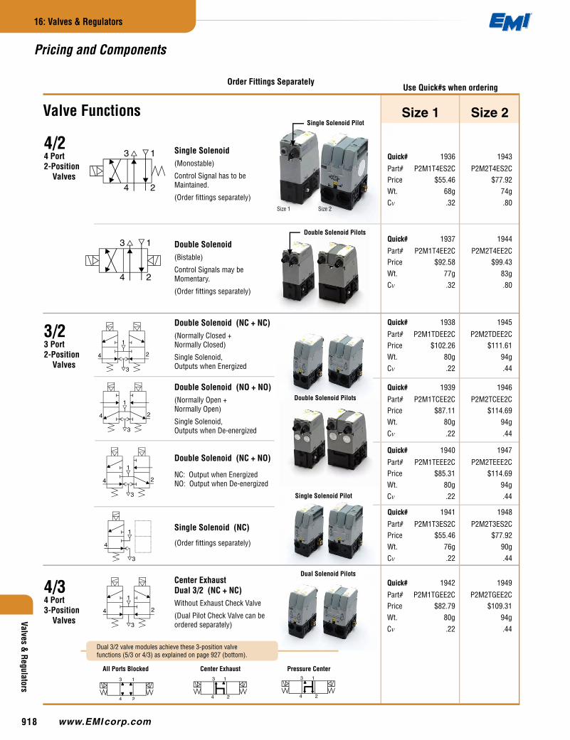
Pricing and Components
Quick# 1941 1948
Part# P2M1T3ES2C P2M2T3ES2CPrice $55.46 $77.92Wt. 76g 90gCv .22 .44
Single Solenoid(Monostable)
Control Signal has to be Maintained.
(Order fittings separately)
4/24 Port 2-Position Valves
3/23 Port 2-Position Valves
4/34 Port 3-Position Valves
Size 1 Size 2
Double Solenoid(Bistable)
Control Signals may be Momentary.
(Order fittings separately)
Double Solenoid (NC + NC)(Normally Closed + Normally Closed)
Single Solenoid, Outputs when Energized
Double Solenoid (NO + NO)(Normally Open + Normally Open)
Single Solenoid, Outputs when De-energized
Double Solenoid (NC + NO)
NC: Output when Energized NO: Output when De-energized
Center Exhaust Dual 3/2 (NC + NC)Without Exhaust Check Valve
(Dual Pilot Check Valve can be ordered separately)
Single Solenoid (NC)
(Order fittings separately)
Valve Functions
Use Quick#s when orderingOrder Fittings Separately
Dual 3/2 valve modules achieve these 3-position valve functions (5/3 or 4/3) as explained on page 927 (bottom).
Quick# 1936 1943
Part# P2M1T4ES2C P2M2T4ES2CPrice $55.46 $77.92Wt. 68g 74gCv .32 .80
Quick# 1937 1944
Part# P2M1T4EE2C P2M2T4EE2CPrice $92.58 $99.43Wt. 77g 83gCv .32 .80
Quick# 1938 1945
Part# P2M1TDEE2C P2M2TDEE2CPrice $102.26 $111.61Wt. 80g 94gCv .22 .44
Quick# 1939 1946
Part# P2M1TCEE2C P2M2TCEE2CPrice $87.11 $114.69Wt. 80g 94gCv .22 .44
Quick# 1940 1947
Part# P2M1TEEE2C P2M2TEEE2CPrice $85.31 $114.69Wt. 80g 94gCv .22 .44
Quick# 1942 1949
Part# P2M1TGEE2C P2M2TGEE2CPrice $82.79 $109.31Wt. 80g 94gCv .22 .44
Single Solenoid Pilot
Double Solenoid Pilots
Double Solenoid Pilots
Single Solenoid Pilot
Dual Solenoid Pilots
Pressure CenterCenter ExhaustAll Ports Blocked
®
918

0-60 psi
0-120 psi
Symbol Type Operator Part number
4-way, 2-positionSingle solenoid P2M1S4ES2C
Single air pilot P2M1S4PS
4-way, 2-positionDouble solenoid P2M1S4EE2C
Double air pilot P2M1S4PP
3-way, 2-position, dual valve, NC/NC w/ exhaust check
Double solenoid P2M1SDEE2C
Double air pilot P2M1SDPP
3-way, 2-position, dual valve, NO/NO w/ exhaust check
Double solenoid P2M1SCEE2C
Double air pilot P2M1SCPP
3-way, 2-position, dual valve, NC/NO w/ exhaust check Double solenoid P2M1SEEE2C
3-way, 2-position, NC w/ exhaust check
Single solenoid P2M1S3ES2C
Single air pilot P2M1S3PS
3-way, 2-position, dual valve, NC/NC Double solenoid P2M1SGEE2C
3
1
4 2
3
1
4 2
3
1
4 2
3
1
4 2
3
1
4
3 1
4 2
3 1
4 2
3
1
4 2
Valv
es &
Reg
ulat
ors
16: Valves & Regulators
216-535-4848
Size 2Description Quick# Part# Price Quick# Part# PriceDIN Rail - for mounting 5073 EL-704W $18.92 5073 EL-704W $18.920–60psi Regulator Gauge 1960 P2M1K0GL $9.07 1960 P2M1K0GL $9.070–120psi Regulator Gauge 1961 P2M1K0GN $9.07 1961 P2M1K0GN $9.07Muffler (for Exhaust Port) 1966 MMDVA1 $9.89 1977 MMDVA2 $9.89Plug 1967 PMDYY1 $3.94 1978 PMDYY2 $5.95Double Male Union: 1968 HMDXX1 $4.48 1979 HMDXX2 $4.83Elbow: 4mm OD tube 1962 CMD04-1 $4.55Elbow: 6mm OD tube 1963 CMD06-1 $4.61 1969 CMD06-2 $5.11Elbow: 8mm OD tube 1970 CMD08-2 $5.52Elbow: 10mm OD tube 1971 CMD10-2 $5.52Elbow: 12mm OD tube 1972 CMD12-2 $8.02Straight: 4mm OD tube 1964 FMD04-1 $3.26Straight: 6mm OD tube 1965 FMD06-1 $3.26 1973 FMD06-2 $4.61Straight: 8mm OD tube 1974 FMD08-2 $4.98Straight: 10mm OD tube 1975 FMD10-2 $4.98Straight: 12mm OD tube 1976 FMD12-2 $6.64
Supply
Intermediate SetWith four Configuration Plates (Order fittings Separately)
Dual Flow Control Module(Can be located remotely, or directly on valve island by using two double male unions. Order separately, below.)
Pressure Regulator
Order Gauge Separately (see below)
(Can be located remotely, or directly on valve island by using two double male unions. Order separately, see below.)
Intermediate Module
Pneumatic Head & Tail SetRequires size 2 fittings.(Order fittings Separately)
Peripheral
Accessories
M8 Connector for Solenoid Pilots (with 5m Cable)
Use this connector with new valve island installations. Integrated LED indicator and voltage surge suppression.
M8 Connector for Solenoid Pilots (no Cable)
Use this connector when you have pre-existing cables, (typically when replacing an old valve island). Threads into the solenoid pilots on the back of the valves.
Head / Tail Module
Dual Pilot Operated Check Valve(Can be located remotely, or directly on valve island by using two double male unions. Order separately, below.)
Size 1
Quick# 1950
Part# P2M2HXT01Price $23.22Wt. 64g
Quick# 1951
Part# P2M2BXT0APrice $22.68Wt. 42g
Quick# 1980
Part# P8LS08L526CPrice $19.49Wt. 148g
Quick# 1981
Part# P8CS0803JPrice $19.00Wt. 12g
Quick# 1954 1958
Part# P2M1PXSL P2M2PXSLPrice $36.13 $40.30Wt. 115g 140g
Quick# 1955 1959
Part# P2M1PXSN P2M2PXSNPrice $36.13 $41.13Wt. 115g 140g
Quick# 1952 1956
Part# P2M1PXFA P2M2PXFAPrice $34.09 $50.05Wt. 30g 45g
Quick# 1953 1957
Part# P2M1PXCA P2M2PXCAPrice $28.00 $34.50Wt. 25g 40g
Size 1 Size 2
These components fit Size 1 & Size 2
®
919
Valves & Regulators
16: Valves & Regulators
www.EMI corp.com
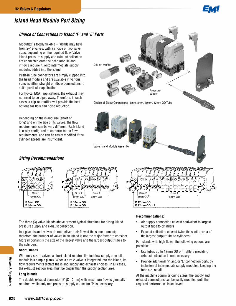
Island Head Module Port Sizing
Choice of Connections to Island ‘P’ and ‘E’ Ports
The three (3) valve islands above present typical situations for sizing island pressure supply and exhaust collection.
In a given island, valves do not deliver their flow at the same moment; therefore, the number of valves in an island is not the major factor to consider. More important is the size of the largest valve and the largest output tubes to the cylinders.
Short Islands
With only size 1 valves, a short island requires limited flow supply (the tail module is a simple plate). When a size 2 valve is integrated into the island, its flow requirements dictate the island supply and exhaust choices. In all cases, the exhaust section area must be bigger than the supply section area.
Long Islands
The double exhaust connector ‘E’ (Ø 12mm) with maximum flow is generally required, while only one pressure supply connector ‘P’ is necessary.
Recommendations:
• Air supply connection at least equivalent to largest output tube to cylinders
• Exhaust collection at least twice the section area of the largest output tube to cylinders
For islands with high flows, the following options are possible:
• Use tubes up to 12mm OD or mufflers providing exhaust collection is not necessary
• Provide additional ‘P’ and/or ‘E’ connection ports by inclusion of intermediate supply modules, keeping the tube size small
At the machine commissioning stage, the supply and exhaust connections can be easily modified until the required performance is achieved.
Depending on the island size (short or long) and on the size of its valves, the flow requirements can be very different. Each island is easily configured to conform to the flow requirements, and can be easily modified if the cylinder speeds are insufficient.
Moduflex is totally flexible – islands may have from 2–19 valves, with a choice of two valve sizes, depending on the required flow. Valve island pressure supply and exhaust collection are connected onto the head module and, if flows require it, onto intermediate supply modules added into the island.
Push-in tube connectors are simply clipped into the head module and are available in various sizes as either straight or elbow connections to suit a particular application.
For typical EOAT applications, the exhaust may not need to be piped away. Therefore, in such cases, a clip-on muffler will provide the best options for flow and noise reduction.
Sizing Recommendations
Pressuresupply
Clip-on Muffler
Choice of Elbow Connectors: 6mm, 8mm, 10mm, 12mm OD Tube
Size 16mm OD
Size 28mm OD
Size 16mm OD
P 6mm ODE 10mm OD
P 10mm ODE 12mm OD
Size 28mm OD
Size 16mm OD
P 12mm ODE 12mm OD x 2
Valve Island Module Assembly
®
920

Valv
es &
Reg
ulat
ors
16: Valves & Regulators
216-535-4848
Island Division into Different Pressure Sections
Valve islands may require two (2) or more different pressure sections. The universal intermediate supply module is available to provide any required combination, as shown by the following examples.
Order Quick# 1951 (Part# P2M2BXT0A)
The universal intermediate supply module is supplied with four (4) configuration plates that achieve two (2) functions:
1. Block ‘P’ or ‘E’ channel, or none, or both;
2. Present a simple diagram on the island front to indicate the internal configuration.
Typical Short Island with Single Supply and Exhaust Collection.
Low-Flow Section
P Pressure Section Atmosphere Vacuum Section
Vacuum Draw
Vacuum
Typical Long Island with Double Supply and Exhaust Collection.
‘P’ and ‘E’ Channels are Both Open.
Two-Section Island for Different Pressures ‘P’ and ‘P1’.
‘P’ Channel is Blocked.
‘E’ Channel is Open.
Two-Section Island for Exhaust Separation of High- Flow Valves.
‘P’ Channel is Open.
‘E’ Channel is Blocked.
Two-Section Island:
• One Section with ‘P’ Pressure
• One Section with Vacuum
‘P’ and ‘E’ Channels are Both Blocked.
P Pressure Section P1 Pressure Section
High-Flow Section
®
921
Valves & Regulators
16: Valves & Regulators
www.EMI corp.com
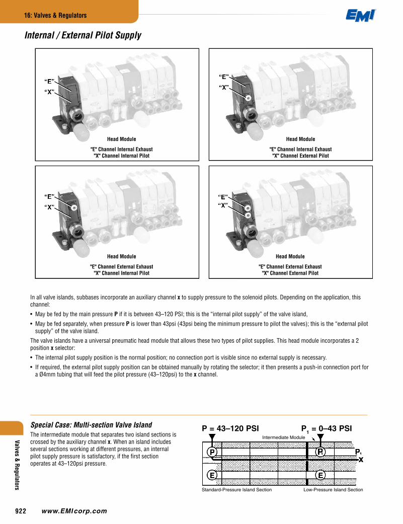
In all valve islands, subbases incorporate an auxiliary channel x to supply pressure to the solenoid pilots. Depending on the application, this channel:
• May be fed by the main pressure P if it is between 43–120 PSI; this is the “internal pilot supply” of the valve island,
• May be fed separately, when pressure P is lower than 43psi (43psi being the minimum pressure to pilot the valves); this is the “external pilot supply” of the valve island.
The valve islands have a universal pneumatic head module that allows these two types of pilot supplies. This head module incorporates a 2 position x selector:
• The internal pilot supply position is the normal position; no connection port is visible since no external supply is necessary.
• If required, the external pilot supply position can be obtained manually by rotating the selector; it then presents a push-in connection port for a Ø4mm tubing that will feed the pilot pressure (43–120psi) to the x channel.
Special Case: Multi-section Valve IslandThe intermediate module that separates two island sections is crossed by the auxiliary channel x. When an island includes several sections working at different pressures, an internal pilot supply pressure is satisfactory, if the first section operates at 43–120psi pressure.
Intermediate Module
P = 43–120 PSI P1 = 0–43 PSI
Standard-Pressure Island Section Low-Pressure Island Section
Internal / External Pilot Supply
Head Module
"E" Channel Internal Exhaust "X" Channel Internal Pilot
Head Module
"E" Channel Internal Exhaust "X" Channel External Pilot
Head Module
"E" Channel External Exhaust "X" Channel Internal Pilot
Head Module
"E" Channel External Exhaust "X" Channel External Pilot
®
922
Valv
es &
Reg
ulat
ors
16: Valves & Regulators
216-535-4848
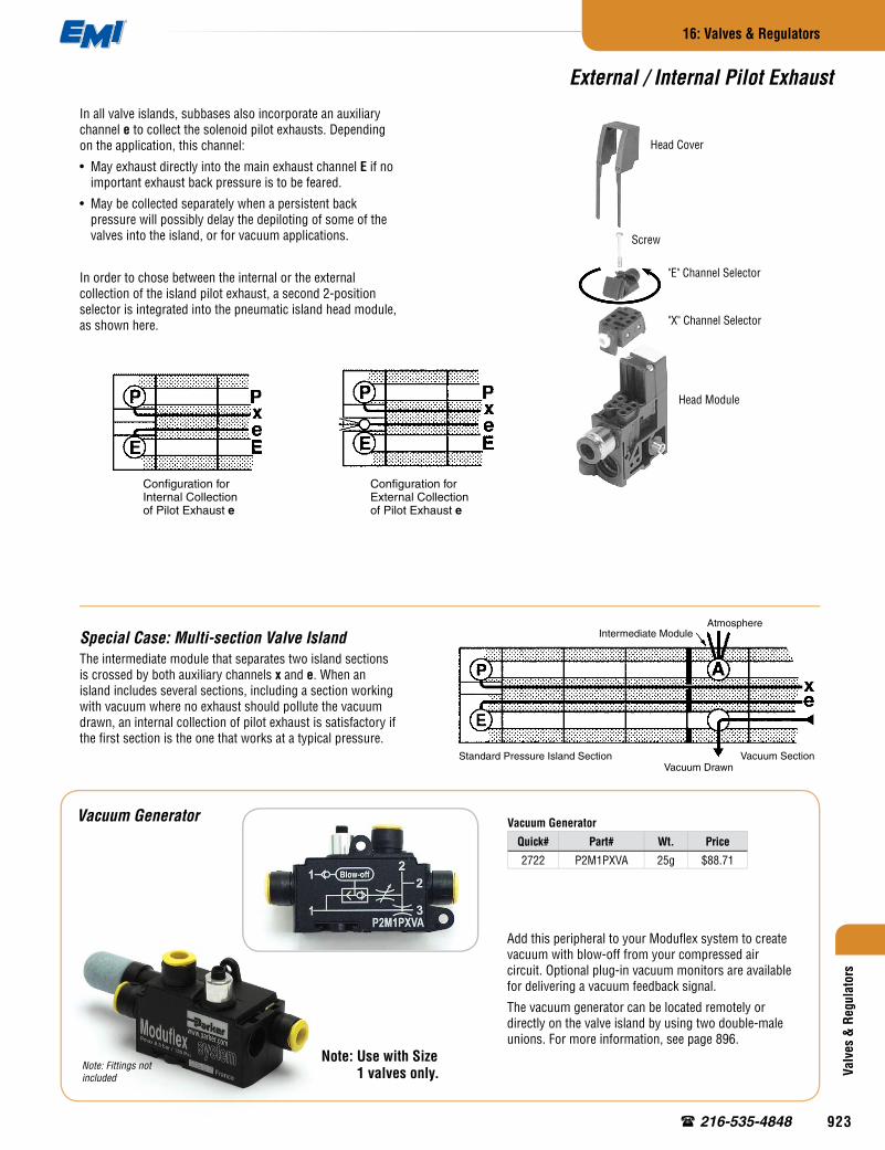
External / Internal Pilot Exhaust
In all valve islands, subbases also incorporate an auxiliary channel e to collect the solenoid pilot exhausts. Depending on the application, this channel:
• May exhaust directly into the main exhaust channel E if no important exhaust back pressure is to be feared.
• May be collected separately when a persistent back pressure will possibly delay the depiloting of some of the valves into the island, or for vacuum applications.
In order to chose between the internal or the external collection of the island pilot exhaust, a second 2-position selector is integrated into the pneumatic island head module, as shown here.
Special Case: Multi-section Valve IslandThe intermediate module that separates two island sections is crossed by both auxiliary channels x and e. When an island includes several sections, including a section working with vacuum where no exhaust should pollute the vacuum drawn, an internal collection of pilot exhaust is satisfactory if the first section is the one that works at a typical pressure.
Configuration for Internal Collection of Pilot Exhaust e
Configuration for External Collection of Pilot Exhaust e
Vacuum Generator
Quick# Part# Wt. Price
2722 P2M1PXVA 25g $88.71
Vacuum Generator
Add this peripheral to your Moduflex system to create vacuum with blow-off from your compressed air circuit. Optional plug-in vacuum monitors are available for delivering a vacuum feedback signal.
The vacuum generator can be located remotely or directly on the valve island by using two double-male unions. For more information, see page 896.
Note: Use with Size 1 valves only.
Intermediate Module
Standard Pressure Island SectionVacuum Drawn
Vacuum Section
Atmosphere
Note: Fittings not included
Head Cover
Screw
"E" Channel Selector
"X" Channel Selector
Head Module
®
923

Valves & Regulators
16: Valves & Regulators
www.EMI corp.com
Valve Islands for Vacuum Applications
Pneumatic automation is often combined with vacuum applications:
• To pick up parts and to move them;
• To vacuum pack or to process under vacuum.
Within electro-pneumatic circuits and machines, these pneumatic valve islands can simplify circuit design and installation of combined pneumatic and vacuum systems.
The Venturi device is also called an “ejector” or a vacuum generator and is well known to pneumatic engineers. It produces vacuum from an air pressure supply. The air jet generates a fast moving flow stream that draws the surrounding atmospheric air. The resulting air movement creates a vacuum when the entry of atmospheric air is blocked by a part.
This simple and compact system replaces costly and cumbersome vacuum pumps and their piping. It is mostly used to pick up and move parts.
The vacuum pad that picks up the part is ideally combined with the Venturi device.
In order to supply the Venturi, a single 3/2 NC valve is integrated into the closest valve island. To limit air consumption, it is advised to adjust the pressure that reaches the Venturi. This is easily done by adding a pressure regulation module to the valve island.
If an automatic blowoff is required, (in addition to the Venturi supply), a double 3/2 NC + NC will control the complete system:
• One 3/2 for the Venturi supply;
• One 3/2 for the automatic blowoff. The integrated exhaust non-return valve in all 3/2 modules size 1 will prevent external air from polluting the venturi vacuum.
Providing Controls for Vacuum Venturi Devices
Venturi
Supply
Venturi Supply
Venturi Device
VacuumPad
Part
Automatic Blowoff
Venturi Blowoff
Double 3/2NC + NC
Single 3/2 NC
Venturi Device
VacuumPad
Part
®
924
Plug
Valv
es &
Reg
ulat
ors
16: Valves & Regulators
216-535-4848
Valve Islands for Vacuum Applications
Pressure and Vacuum Combined in the Same Island
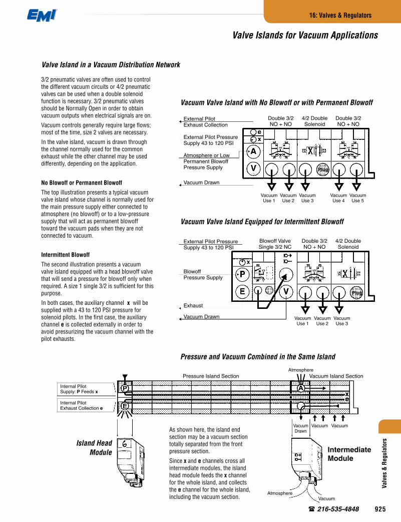
3/2 pneumatic valves are often used to control the different vacuum circuits or 4/2 pneumatic valves can be used when a double solenoid function is necessary. 3/2 pneumatic valves should be Normally Open in order to obtain vacuum outputs when electrical signals are on.
Vacuum controls generally require large flows; most of the time, size 2 valves are necessary.
In the valve island, vacuum is drawn through the channel normally used for the common exhaust while the other channel may be used differently, depending on the application.
No Blowoff or Permanent Blowoff
The top illustration presents a typical vacuum valve island whose channel is normally used for the main pressure supply either connected to atmosphere (no blowoff) or to a low-pressure supply that will act as permanent blowoff toward the vacuum pads when they are not connected to vacuum.
Intermittent Blowoff
The second illustration presents a vacuum valve island equipped with a head blowoff valve that will send a pressure for blowoff only when required. A size 1 single 3/2 is sufficient for this purpose.
In both cases, the auxiliary channel x will be supplied with a 43 to 120 PSI pressure for solenoid pilots. In the first case, the auxiliary channel e is collected externally in order to avoid pressurizing the vacuum channel with the pilot exhausts.
Vacuum Valve Island with No Blowoff or with Permanent Blowoff
Vacuum Valve Island Equipped for Intermittent Blowoff
Valve Island in a Vacuum Distribution Network
External Pilot Exhaust Collection
External Pilot Pressure Supply 43 to 120 PSI
Atmosphere or Low Permanent Blowoff Pressure Supply
Vacuum Drawn
Vacuum Vacuum Vacuum Vacuum Vacuum Use 1 Use 2 Use 3 Use 4 Use 5
4/2 Double Solenoid
Double 3/2NO + NO
Double 3/2NO + NO
Plug
External Pilot Pressure Supply 43 to 120 PSI
BlowoffPressure Supply
Exhaust
Vacuum Drawn Vacuum Vacuum Vacuum Use 1 Use 2 Use 3
Double 3/2 NO + NO
Blowoff Valve Single 3/2 NC
4/2 Double Solenoid
As shown here, the island end section may be a vacuum section totally separated from the front pressure section.
Since x and e channels cross all intermediate modules, the island head module feeds the x channel for the whole island, and collects the e channel for the whole island, including the vacuum section.
Pressure Island Section
Internal Pilot Exhaust Collection e
Internal PilotSupply: P Feeds x
Vacuum Island Section
VacuumDrawn
Vacuum Vacuum
Atmosphere
AtmosphereVacuum
Island Head Module Intermediate
Module
®
925

3
4 2
1
4 2
3
1
4 2
53
3
1
4 2
1
LockLock Lock
3
4 2
1
4 2
3
1
4 2
53
3
1
4 2
1
LockLock Lock
3
4 2
1
4 2
3
1
4 2
53
3
1
4 2
1
LockLock Lock
3
4 2
1
4 2
3
1
4 2
53
3
1
4 2
1
LockLock Lock
3
4 2
1
4 2
3
1
4 2
53
3
1
4 2
1
LockLock Lock
3
4 2
1
4 2
3
1
4 2
53
3
1
4 2
1
LockLock Lock
3
4 2
1
4 2
3
1
4 2
53
3
1
4 2
1
LockLock LockValves &
Regulators
16: Valves & Regulators
www.EMI corp.com
3-position valves are traditional for positioning, blocking or venting pneumatic cylinders.
Because pneumatic valves are now commonly assembled into islands, 3-position valve functions have to be adapted in order to meet all applications allowing for exhaust back pressures and long distances between valves and cylinders.
3-Position Center Exhaust – Pressure-Free Cylinder
3-PositionPressure Center
Double 3/2NO + NO
Cylinder positioning is achieved with both chambers under pressure.
5/3 ValveCenter Exhaust
Pressure-Free Cylinder
Double 3/2NC + NC(version with no exhaust check valves)
Solution:common exhaust balances back pressure effect on the cylinder.
Problem:island exhaustback pressuresreach the cylinderand move itunexpectedly.
Using Moduflex Valves – Double 3/2 NC + NCTraditional Configuration
Using Moduflex Valves – Double 3/2 NO + NOTraditional Configuration
3-Position Pressure Center – Cylinder Fitted with Locking Device
Typical 3-Position Valve Applications
To Valves
®
926
3
1
1
4 2
4 2
1
4 2
1
4 23
4 2
1
4 2
3
1
4 2
3
4 2
1
4 2
3
1
4 2
53
3
1
4 2
1
LockLock Lock
3
4 2
1
4 2
3
1
4 2
53
3
1
4 2
1
LockLock Lock
Valv
es &
Reg
ulat
ors
16: Valves & Regulators
216-535-4848
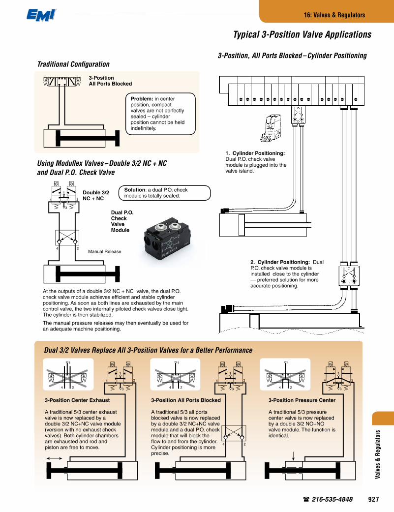
3-Position, All Ports Blocked – Cylinder PositioningTraditional Configuration
3-Position Center Exhaust
A traditional 5/3 center exhaust valve is now replaced by a double 3/2 NC+NC valve module (version with no exhaust check valves). Both cylinder chambers are exhausted and rod and piston are free to move.
3-Position All Ports Blocked
A traditional 5/3 all ports blocked valve is now replaced by a double 3/2 NC+NC valve module and a dual P.O. check module that will block the flow to and from the cylinder. Cylinder positioning is more precise.
3-Position Pressure Center
A traditional 5/3 pressure center valve is now replaced by a double 3/2 NO+NO valve module. The function is identical.
Dual 3/2 Valves Replace All 3-Position Valves for a Better Performance
At the outputs of a double 3/2 NC + NC valve, the dual P.O. check valve module achieves efficient and stable cylinder positioning. As soon as both lines are exhausted by the main control valve, the two internally piloted check valves close tight. The cylinder is then stabilized.
The manual pressure releases may then eventually be used for an adequate machine positioning.
3-PositionAll Ports Blocked
Dual P.O. CheckValve Module
Problem: in center position, compact valves are not perfectly sealed – cylinder position cannot be held indefinitely.
1. Cylinder Positioning: Dual P.O. check valve module is plugged into the valve island.
2. Cylinder Positioning: Dual P.O. check valve module is installed close to the cylinder — preferred solution for more accurate positioning.
Using Moduflex Valves – Double 3/2 NC + NC and Dual P.O. Check Valve
Solution: a dual P.O. check module is totally sealed.
Double 3/2NC + NC
Manual Release
Typical 3-Position Valve Applications
®
927

Exhaust Back Pressure PE
Valves & Regulators
16: Valves & Regulators
www.EMI corp.com
Collected Exhaust using Intermediate Modules
Depending on the sizes of the cylinders and the speed required by the application, back pressures in the island may be efficiently evacuated through multiple exhaust collections using Intermediate Modules.
Another method to block exhaust back pressures when they may affect the application is to isolate the valves in the island that control the largest and fastest cylinders. This is easily achieved with an intermediate module.
Blocking Exhaust Back Pressures Inside the Island
Limiting Exhaust Back Pressures in a Valve Island
• C cylinder, large and fast moving, may feed the island exhaust channel with an exhaust back pressure PE.
• Such a back pressure is normally under 14 PSI. Since the opposite pressure, P, is high, it will not affect double-acting cylinders, such as B.
• However, such a back pressure may affect a single-acting cylinder A if its pressure threshold is low.
Blocking Exhaust Back Pressures with 3/2 Modules
Single-Acting Cylinder Controlled by a 3/2 Valve
Double-Acting Cylinders Controlled by 4/2 Valve Modules
Integrated Exhaust Non-Return Valve in All Single and Double 3/2 Valve Modules Size 1
Consequently, small single-acting cylinders may pop out unexpectedly whenever an exhaust back pressure rises into the island.
To avoid such malfunctions, Size 1 3/2 valve modules feature integrated exhaust non-return valves that will block any exhaust back pressure from reaching the acting cylinders they control.
Intermediate Module with the Configuration Plate Blocking the Island Exhaust Channel
In a valve island, it is important to limit exhaust back pressures to about 14 PSI maximum so that all double-acting cylinders efficiently achieve their function at 87 PSI.
Exhaust Through Mufflers
For applications that do not require the exhausts to be collected, a plug-in muffler into each exhaust port of the island will evacuate exhaust back pressures.
High Flow SectionLow Flow Section
Exhaust Back Pressure Control
®
928

Valv
es &
Reg
ulat
ors
16: Valves & Regulators
216-535-4848
Double Solenoid4/2 Valves
These cylinders retract in a chosen position.
This cylinder becomes totally pressure free.
Single Solenoid4/2 and 3/2 Valves
Single SolenoidDouble 3/2 NC + NC
Single SolenoidDouble 3/2 NC + NC
Dual P.O.Check ValveModule
This cylinder is blocked in position, even during its stroke
These cylinders maintain their last position and action in case of electrical cutoff.
Designers of electro-pneumatic machines have to define the cylinder positioning when electrical supply gets cut off; for example, for an emergency requirement.
A clamping cylinder will maintain its action so that the part it is holding does not take off under the action of a cutting tool.
On the contrary, a stamping cylinder will retract in its initial position, and a transfer cylinder may be blocked along its stroke.
Pneumatic valve islands provide all means to obtain emergency machine positioning. The different solutions are presented on the valve island above.
• A, B and C double-acting cylinders are controlled with double solenoid valves. These will keep their position in case of electrical cutoff. The cylinders will maintain their positions and actions.
Single / Double Solenoid Valve Choice for Adequate Emergency Positioning
• D and E double-acting cylinders are controlled with single solenoid valves. Their spring return will bring them back in the initial position corresponding to the required initial position of the cylinder.
• F, G, and H single-acting cylinders will retract as well with the help of their spring.
• Controlled with a single solenoid double 3/2 NC+NC valve, the double-acting J cylinder will be exhausted on both chambers when an electrical cutoff happens.
• Due to the Double P.O. check valve module, the double-acting K cylinder will be blocked along its stroke.
Valve islands now offer many means to do so with single and double solenoid valves, peripheral modules, integrated dump valves, etc.
Pneumatic cylinder / valve circuit design must take into account the machine positioning in case of electrical supply cutoff or other emergency events.
Valve Islands and Emergency Machine Positioning
®
929
Valves & Regulators
16: Valves & Regulators
www.EMI corp.com
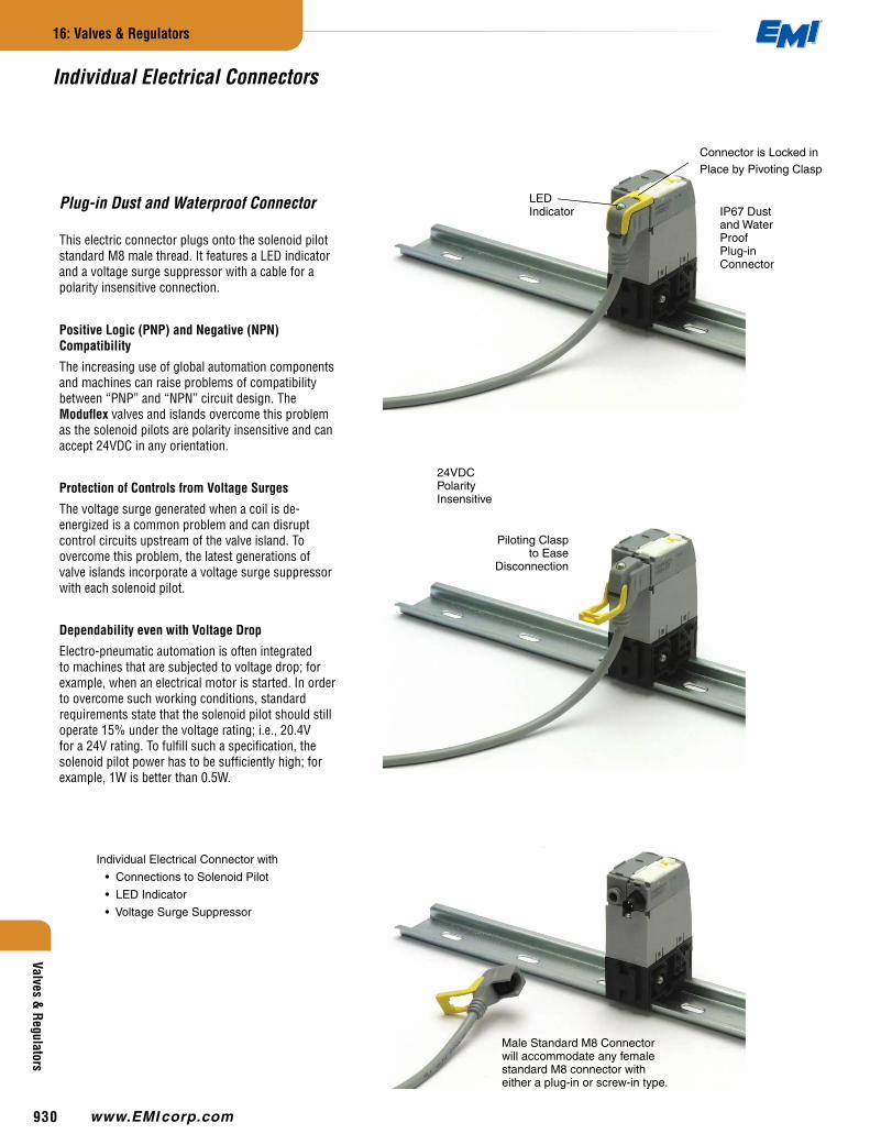
Individual Electrical Connectors
This electric connector plugs onto the solenoid pilot standard M8 male thread. It features a LED indicator and a voltage surge suppressor with a cable for a polarity insensitive connection.
Plug-in Dust and Waterproof Connector
Positive Logic (PNP) and Negative (NPN) Compatibility
The increasing use of global automation components and machines can raise problems of compatibility between “PNP” and “NPN” circuit design. The Moduflex valves and islands overcome this problem as the solenoid pilots are polarity insensitive and can accept 24VDC in any orientation.
Protection of Controls from Voltage Surges
The voltage surge generated when a coil is de-energized is a common problem and can disrupt control circuits upstream of the valve island. To overcome this problem, the latest generations of valve islands incorporate a voltage surge suppressor with each solenoid pilot.
Dependability even with Voltage Drop
Electro-pneumatic automation is often integrated to machines that are subjected to voltage drop; for example, when an electrical motor is started. In order to overcome such working conditions, standard requirements state that the solenoid pilot should still operate 15% under the voltage rating; i.e., 20.4V for a 24V rating. To fulfill such a specification, the solenoid pilot power has to be sufficiently high; for example, 1W is better than 0.5W.
IP67 Dustand WaterProofPlug-inConnector
24VDCPolarityInsensitive
Individual Electrical Connector with
• Connections to Solenoid Pilot
• LED Indicator
• Voltage Surge Suppressor
Piloting Clasp to Ease
Disconnection
Connector is Locked inPlace by Pivoting Clasp
Male Standard M8 Connector will accommodate any female standard M8 connector with either a plug-in or screw-in type.
LED Indicator
®
930

“T” Series
Fitting Assembly: Pneumatic Connectors are retained by a clip in each module. Assembly is achieved by pushing the fitting into the module and sliding the clip down over the groove in the fitting. Pull fitting to check that it is secure.
Tubing Assembly: Cut tubing squarely & cleanly. Inspect the tubing to insure there are no sharp edges that may nick or cut the o-ring seal. Insert tubing into fitting until it bottoms out. A slight pull on the tube afterwards can help verify it is properly retained / inserted.
Tubing Disassembly: When it is required to remove the tubing from the fitting push the release button in towards the fitting & remove the tubing.
Tubing Reassembly: Inspect the tubing before re-inserting it for any scoring or other damage that would affect the o-ring sealing. It is recommended that for every insertion, the tubing end be trimmed, especially if it has any scoring or damage.
Fitting and Tubing Installation
Torque Rating Solenoid to Valve:3.0 in. lbs.
Use a Torx Screw Driver
Torque Rating Valve to Base:4.5 in. lbs.
Use a Torx Screw Driver
Valv
es &
Reg
ulat
ors
16: Valves & Regulators
216-535-4848
Connections to PLCs and Other Controls
The two (2) wires of each connector cable can be taken directly to the output terminals of a PLC or field bus module.
If all outputs have a single common terminal, it will be necessary to use an intermediate terminal block with the commons linked.
Connections outside enclosures may be IP67 protected, using the standard M8 or M12 connectors of a terminal box.
For safety and standardization reasons, most machine builders now use 24VDC. This convergence towards only one voltage leads to a simpler system with a unique solenoid pilot. In order to cater to the man-machine dialog requirements, this solenoid pilot manual override is both multifunctional and adaptable to each stage, from the machine installation to its maintenance.
The standard modules have solenoid pilots with multifunction manual overrides:
• Push-release function;
• Push-twist-lock function.
Man-machine dialog is then complete, facilitating the commissioning of each machine subassembly. Later, when electrical controls are connected, the manual override may be adapted.
Depending on the machine and its conditions of use, one may either:
• Keep complete multifunction manual overrides;
• Delete the lock capability by removing the locking stop; this will prevent the manual override from being left in the locked position; or
• Make the manual override completely inoperative when automatic controls take care of access for maintenance. An isolation fork is available for this operation.
Solenoid Pilot with Multifunction and Adaptable Manual Override
Multifunction Manual Override
Manual Override Adaptations
1. Push -Release
2. Push -Twist - Lock
1. Remove Lock Capability
2. Manual Override is Totally Isolated
LockingStop
IsolationFork
®
931
12 mm2 40 mm2
.32 Cv
(400 NI/min)
.80 Cv
(1200 NI/min)
Valves & Regulators
16: Valves & Regulators
www.EMI corp.com
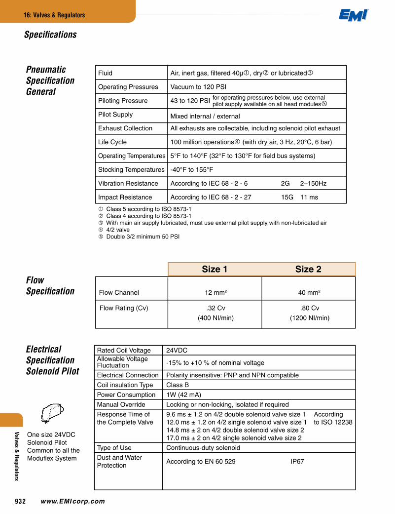
Pneumatic SpecificationGeneral
Mixed internal / external
Electrical SpecificationSolenoid Pilot
Flow Specification Flow Channel
Flow Rating (Cv)
Size 1 Size 2
One size 24VDC Solenoid Pilot Common to all the Moduflex System
Rated Coil Voltage 24VDCAllowable Voltage
-15% to +10 % of nominal voltageFluctuation
Electrical Connection Polarity insensitive: PNP and NPN compatible
Coil insulation Type Class B
Power Consumption 1W (42 mA)
Manual Override Locking or non-locking, isolated if required
Response Time of 9.6 ms ± 1.2 on 4/2 double solenoid valve size 1 According the Complete Valve 12.0 ms ± 1.2 on 4/2 single solenoid valve size 1 to ISO 12238 14.8 ms ± 2 on 4/2 double solenoid valve size 2 17.0 ms ± 2 on 4/2 single solenoid valve size 2
Type of Use Continuous-duty solenoid
Dust and Water According to EN 60 529 IP67
Protection
Specifications
Fluid Air, inert gas, filtered 40µ , dry or lubricated
Operating Pressures Vacuum to 120 PSI
Piloting Pressure 43 to 120 PSI
Pilot Supply
Exhaust Collection All exhausts are collectable, including solenoid pilot exhaust
Life Cycle 100 million operations (with dry air, 3 Hz, 20°C, 6 bar)
Operating Temperatures 5°F to 140°F (32°F to 130°F for field bus systems)
Stocking Temperatures -40°F to 155°F
Vibration Resistance According to IEC 68 - 2 - 6 2G 2–150Hz
Impact Resistance According to IEC 68 - 2 - 27 15G 11 ms
Class 5 according to ISO 8573-1 Class 4 according to ISO 8573-1 With main air supply lubricated, must use external pilot supply with non-lubricated air 4/2 valve Double 3/2 minimum 50 PSI
for operating pressures below, use external pilot supply available on all head modules
®
932
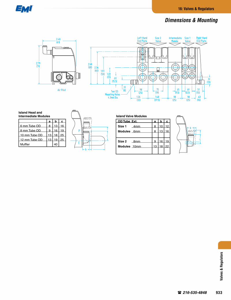
.75(19)
.51(13).63(16)
1.48(37.5)
.98(25)
.98(25)
.98(25)
.98(25)
2.68(68) 2.36
(60)
2.72(69)
1.97(50)
1.65(42)
.87(22)
1.22(31) .61
(15.5)
.31(8)
1.26(32)
.51(13)
.45(11.5)
.49(12.5)
.49(12.5)
Left HandEnd Plate
Right HandEnd Plate
Two (2) Pivoting Locks for DIN Rail Mounting
Two (2)Mounting Holes
4.3mm Dia.
DIN Rail Mounting
or Two (2) Screws Ø4mm Surface Mounting
IntermediateModule
Size 1Valve
Size 2Valve
Two (2)Mounting Holes
4.3mm Dia. 2.56(65)
.91(23)
1.38(35)
.24(6)
DIN Rail 35 x 7mmor 35 x 15mm
a
2.79(71)
Air Pilot
2.40(61)
c
b
c
b
P
E
Valv
es &
Reg
ulat
ors
16: Valves & Regulators
216-535-4848
Island Head and Intermediate Modules
a b c
6 mm Tube OD 8 13 16
8 mm Tube OD 9 16 19
10 mm Tube OD 13 18 25
12 mm Tube OD 13 19 25
Muffler 40
Island Valve Modules
OD Tube Ext. a b c
Size 1 4mm 8 10 12
Modules 6mm 8 13 16
Size 2 8mm 9 16 19
Modules 10mm 13 18 22
Dimensions & Mounting
®
933
Related Documents