IL2477a ENVIROZONE-TSTAT ELECTRIC GRIDDLE Commercial 124ZT, 136ZT, 148ZT, 160ZT, 172ZT Installation and Operation Instructions 2M-W1823 Rev. C 2/11/2015 124ZT

Welcome message from author
This document is posted to help you gain knowledge. Please leave a comment to let me know what you think about it! Share it to your friends and learn new things together.
Transcript
IL2477a
ENVIROZONE-TSTATELECTRIC GRIDDLE
Commercial
124ZT, 136ZT, 148ZT, 160ZT, 172ZT
Installation and Operation
Instructions2M-W1823 Rev. C 2/11/2015
124ZT

2
2M-W
1823
, Env
irozo
ne T
-Sta
t Ele
ctric
Grid
dle
These symbols are intended to alert the user to the presence ofimportant operating and maintenance instructions in the manualaccompanying the appliance.
FOR YOUR SAFTEYDO NOT STORE OR USE GASOLINE OR OTHER FLAMMABLE VAPORS AND LIQUIDS IN
THE VICINTIY OF THIS OR ANY OTHER APPLIANCE.
POST IN PROMINENT LOCATIONINSTRUCTIONS TO BE FOLLOWED IN THE EVENT USER SMELLS GAS. THIS
INFORMATION SHALL BE OBTAINED BY CONSULTING YOUR LOCAL GAS SUPPLIER. AS A MINIMUM, TURN OFF THE GAS AND CALL YOUR GAS COMPANY AND YOUR AUTHORIZED SERVICE AGENT. EVACUATE ALL PERSONNEL FROM THE AREA.
WARNINGIMPROPER INSTALLATION, ADJUSTMENT, ALTERATION, SERVICE OR MAINTENANCE
CAN CAUSE PROPERTY DAMAGE, INJURY OR DEATH. READ THE INSTALLATION, OPERATION & MAINTENANCE INSTRUCTIONS THOROUGHLY BEFORE INSTALLING OR
SERVICING THIS EQUIPMENT. WARNING
RISK OF FIRE OR ELECTRIC SHOCKDO NOT OPEN
WARNING, TO REDUCE THE RISK OF ELECTRICAL SHOCK, DO NOT REMOVE CONTROL PANEL. NO USER-SERVICABLE PARTS INSIDE. REPAIRS SHOULD BE DONE BY AUTHORIZED SERVICE PERSONNEL ONLY.
NOTICEUsing any part other than genuine Lang factory supplied parts relieves the manufacturer of allliability.Lang reserves the right to change specifications and product design without notice. Such revisions do not entitle the buyer to corresponding changes, improvements, additions orreplacements for previously purchased equipment.Due to periodic changes in designs, methods, procedures, policies and regulations,the specifications contained in this sheet are subject to change without notice. While Lang exercises good faith efforts to provide information that is accurate, we are not responsible for errors or omissions in information provided or conclusions reached as aresult of using the specifications. By using the information provided, the user assumes all risks in connection with such use.
MAINTENANCE AND REPAIRSContact your local dealer for service or required maintenance. Please record the model number, serialnumber, voltage and purchase & Installation Information in the area below and have it ready when you call to ensure a faster service.
SAFETY SYMBOL
Model No.:
Serial No.:
Voltage:
1-Phase or 3 Phase:
Purchased From:
Location:
Purchase Date:
Installed Date:

3
2M-W
1823
, Env
irozo
ne T
-Sta
t Ele
ctric
Grid
dle
TABLE OF CONTENTSSpecifications . . . . . . . . . . . . . . . . . . . . . . . . . . . . . 4Equipment Description . . . . . . . . . . . . . . . . . . . . . . . . 5Unpacking . . . . . . . . . . . . . . . . . . . . . . . . . . . . . . . 6Installation Leg Installation . . . . . . . . . . . . . . . . . . . . . . . . . . 7 Ventilation & Clearence . . . . . . . . . . . . . . . . . . . . . . 8 Electrical Connection . . . . . . . . . . . . . . . . . . . . . . . 8 Technical Data . . . . . . . . . . . . . . . . . . . . . . . . . . . 8 Phasing . . . . . . . . . . . . . . . . . . . . . . . . . . . . . . 8Initial Start-Up Pre-Power On . . . . . . . . . . . . . . . . . . . . . . . . . . . 9 Power On . . . . . . . . . . . . . . . . . . . . . . . . . . . . . 9 Seasoning Cooking Surface . . . . . . . . . . . . . . . . . . . . 9Operation General . . . . . . . . . . . . . . . . . . . . . . . . . . . . . . 10 Loading the Griddle . . . . . . . . . . . . . . . . . . . . . . . . 10 Suggested Times and Temperatures . . . . . . . . . . . . . . . 10Maintenance Cleaning . . . . . . . . . . . . . . . . . . . . . . . . . . . . . . 11 Crome Surface Griddle Care . . . . . . . . . . . . . . . . . . . 12Troubleshooting Symptoms / Possible Causes . . . . . . . . . . . . . . . . . . . 13 Possible Causes / Test . . . . . . . . . . . . . . . . . . . . . . 13Wiring Diagram 208/240VAC . . . . . . . . . . . . . . . . . . . . . . . . . . . . 14 480V . . . . . . . . . . . . . . . . . . . . . . . . . . . . . . . . 14Exploded View & Parts List . . . . . . . . . . . . . . . . . . . . . 15-20
PROBLEMS, QUESTIONS or CONCERNS
Before you proceed consult you authorized Lang service agent directoryor
Call the Lang Technical Service Department at 314-678-6315
NOTICE Service on this or any other Lang appliance must be performed by qualified personnel only. Consult your Lang Authorized Service Agent Directory. You can call our service number 314-678-6315 or visit our website www.langworld.com for the service agent nearest you.
4
2M-W
1823
, Env
irozo
ne T
-Sta
t Ele
ctric
Grid
dle
WidthDepth
Height
IL2478
EQUIPMENT SPECIFICATIONS
ELECTRICAL SPECIFICATIONS
Model Volts Hz. PhKw
Total A 1PH. Supply L1 L2 L3 SupplyKw
Total A 1PH. Supply L1 L2 L3 Supply124ZT 208/240 60 1/3 12 58 4 50 29 29 6136ZT 208/240 60 1/3 18 87 2 50 50 50 6148ZT 208/240 60 1/3 24 116 1 75 75 50 3160ZT 208/240 60 1/3 12 58 4 50 29 29 6 18 87 2 50 50 50 6172ZT 208/240 60 1/3 18 87 2 50 50 50 6 18 87 2 50 50 50 6
Model Dimensions (Not including Legs) Clearance from combustible surface
Weight Freight ClassWidth Depth Height Actual Shipping
124ZT 24” (61 cm)
30.4” (77.2 cm)
16.4” (41.6 cm) Sides: 2”, Back: 2”
243 lbs. 280 lbs.
85
110 kg 127 kg124ZTD 36.5” (92.7 cm)
136ZT 36” (91.4 cm)
30.4” (77.2 cm) 368 lbs. 410 lbs.167 kg 186 kg
136ZTD 36.5” (92.7 cm)
148ZT 48” (121.9 cm)
30.4” (77.2 cm) 483 lbs. 515 lbs.220 kg 234 kg
148ZTD 36.5” (92.7 cm)
160ZT 60” (152.4 cm)
30.4” (77.2 cm) 621 lbs. 665 lbs.282 kg 302 kg
160ZTD 36.5” (92.7 cm)
172ZT 72” (183 cm)
30.4” (77.2 cm) 724 lbs. 800 lbs.329 kg 364 kg
172ZTD 36.5” (92.7 cm)
5
2M-W
1823
, Env
irozo
ne T
-Sta
t Ele
ctric
Grid
dle
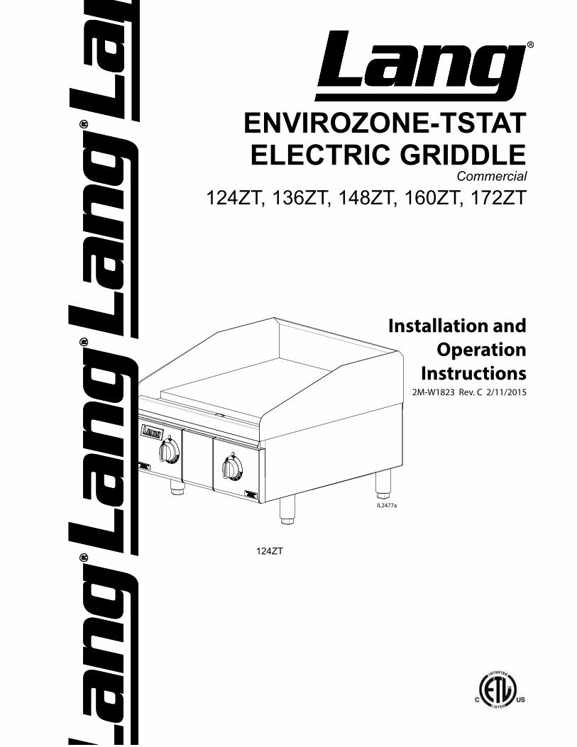
EQUIPMENT DESCRIPTION
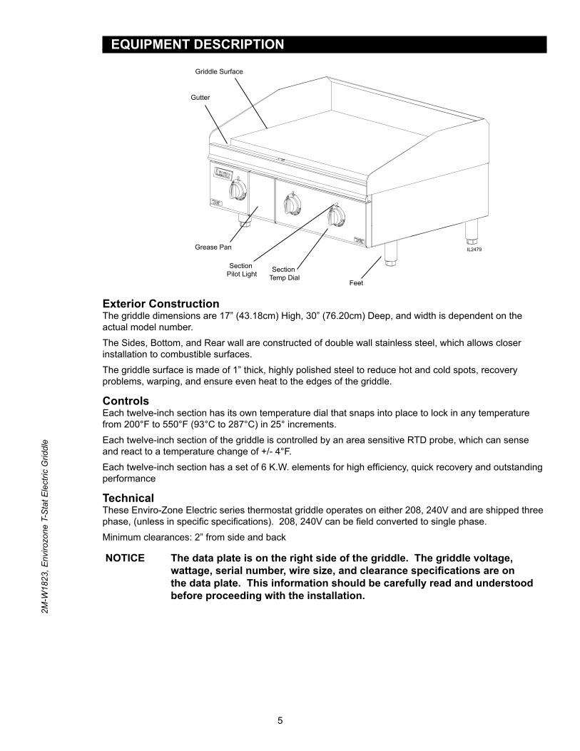
Exterior ConstructionThe griddle dimensions are 17” (43.18cm) High, 30” (76.20cm) Deep, and width is dependent on the actual model number. The Sides, Bottom, and Rear wall are constructed of double wall stainless steel, which allows closer installation to combustible surfaces. The griddle surface is made of 1” thick, highly polished steel to reduce hot and cold spots, recovery problems, warping, and ensure even heat to the edges of the griddle.
ControlsEach twelve-inch section has its own temperature dial that snaps into place to lock in any temperature from 200°F to 550°F (93°C to 287°C) in 25° increments.Each twelve-inch section of the griddle is controlled by an area sensitive RTD probe, which can sense and react to a temperature change of +/- 4°F.Each twelve-inch section has a set of 6 K.W. elements for high efficiency, quick recovery and outstanding performance
TechnicalThese Enviro-Zone Electric series thermostat griddle operates on either 208, 240V and are shipped three phase, (unless in specific specifications). 208, 240V can be field converted to single phase.Minimum clearances: 2” from side and back
NOTICE The data plate is on the right side of the griddle. The griddle voltage, wattage, serial number, wire size, and clearance specifications are on the data plate. This information should be carefully read and understood before proceeding with the installation.
Griddle Surface
Gutter
Section Temp Dial
Section Pilot Light
Grease Pan
Feet
IL2479
6
2M-W
1823
, Env
irozo
ne T
-Sta
t Ele
ctric
Grid
dle
UNPACKING
Receiving the GriddleUpon receipt, check for freight damage, both visible and concealed. Visible damage should be noted on the freight bill at the time of delivery and signed by the carrier’s agent. Concealed loss or damage means it does not become apparent until the merchandise has been unpacked. If concealed loss or damage is discovered upon unpacking, make a written request for inspection by the carrier’s agent within 15 days of delivery. All packing material should be kept for inspection. Do not return damaged merchandise to Star Manufacturing Company. File your claim with the carrier.
LocationPrior to un-crating, move the griddle as near to its intended location as practical. The crating will help protect the unit from the physical damage normally associated with moving it through hallways and doorways.
Un-cratingThe griddle will arrive completely assembled inside a wood frame and strapped to a skid. Cut the straps and remove the wood frame. The griddle can now be removed from the skid.
THE UNIT IS EXTREMELY HEAVY. FOR SAFE HANDLING, INSTALLER SHOULD OBTAIN HELP AS NEEDED, OR EMPLOY APPROPRIATE MATERIALS HANDLING EQUIPMENT (SUCH AS A FORKLIFT, DOLLY, OR PALLET JACK) TO REMOVE THE UNIT FROM THE SKID AND MOVE IT TO THE PLACE OF INSTALLATION.
ANY STAND, COUNTER OR OTHER DEVICE ON WHICH GRIDDLE WILL BE LOCATED MUST BE DESIGNED TO SUPPORT THE WEIGHT OF THE GRIDDLE.
SHIPPING STRAPS ARE UNDER TENSION AND CAN SNAP BACK WHEN CUT.
CAUTION
CAUTION
WARNING
7
2M-W
1823
, Env
irozo
ne T
-Sta
t Ele
ctric
Grid
dle
INSTALLATION
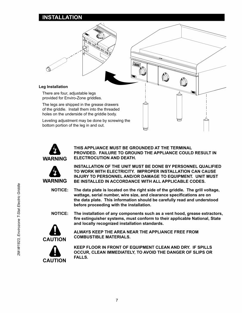
Leg InstallationThere are four, adjustable legs provided for Enviro-Zone griddles. The legs are shipped in the grease drawers of the griddle. Install them into the threaded holes on the underside of the griddle body.Leveling adjustment may be done by screwing the bottom portion of the leg in and out.
IL2480
: THIS APPLIANCE MUST BE GROUNDED AT THE TERMINAL PROVIDED. FAILURE TO GROUND THE APPLIANCE COULD RESULT IN ELECTROCUTION AND DEATH.
INSTALLATION OF THE UNIT MUST BE DONE BY PERSONNEL QUALIFIED TO WORK WITH ELECTRICITY. IMPROPER INSTALLATION CAN CAUSE INJURY TO PERSONNEL AND/OR DAMAGE TO EQUIPMENT. UNIT MUST BE INSTALLED IN ACCORDANCE WITH ALL APPLICABLE CODES.
NOTICE: The data plate is located on the right side of the griddle. The grill voltage, wattage, serial number, wire size, and clearance specifications are on the data plate. This information should be carefully read and understood before proceeding with the installation.
NOTICE: The installation of any components such as a vent hood, grease extractors, fire extinguisher systems, must conform to their applicable National, State and locally recognized installation standards.
ALWAYS KEEP THE AREA NEAR THE APPLIANCE FREE FROM COMBUSTIBLE MATERIALS.
KEEP FLOOR IN FRONT OF EQUIPMENT CLEAN AND DRY. IF SPILLS OCCUR, CLEAN IMMEDIATELY, TO AVOID THE DANGER OF SLIPS OR FALLS.
CAUTION
WARNING
WARNING
CAUTION

8
2M-W
1823
, Env
irozo
ne T
-Sta
t Ele
ctric
Grid
dle
INSTALLATION cont.
Ventilation and ClearancesStandard minimum clearance from combustible construction is as follows.2” from side2” from back
These griddles may be set directly, without legs, on a curbed base or non-combustible surface.If the griddle is set without legs on a non-combustible floor or a curbed base, maintain a 4-inch back clearance.Do not install the griddle directly against a non-combustible back wall or surface.Do not install the griddle closer than 12 inches from an uncontrolled heat source (char broiler etc.).Keep the appliance area free and clear of combustible material and do not obstruct the flow of combustion or ventilation air.
Electrical ConnectionDetach cover on junction box at rear of unit. There is one power supply connection on the 2, 3, and 4-foot griddles. There are two power supply connections on 5 and 6-foot griddles. Refer to the power supply chart in the Technical Specification Data portion of this manual (pg 4 & 5), for proper power supply size.There is (1) one 1 1/4-inch conduit knockout on 2, 3 and 4-foot griddles located at the rear of the griddle, through the back and the bottom of the griddle body. There are (2) two 1 1/4-inch conduit knockouts provided on the 5 and 6-foot griddles. Use a supply wire suitable for at least 90°C/194°F.This griddle is shipped from the factory set up for a three phase service. On 208V, 220V & 240V the wiring can be changed in the supply terminal junction box to convert the griddle to single phase.
Technical DataRe-PhasingAll griddles are shipped from the factory set up for a three-phase service. Rearrange the wires in the power supply terminal block to convert the griddle to single phase. Re-phasing the griddle is not chargeable to Lang Manufacturing Company as warranty. To convert to single-phase have a Lang Authorized Service Agent, follow this chart.
MODEL NUMBER
TOTAL K.W.
NOMINAL AMPS PER LINESINGLE PHASETHREE PHASE
208 Volt 240 Volt 480 Volt208V 240VL1 L2 L3 L1 L2 L3 L1 L2 L3
24” 12 50 28.8 28.8 43.3 25 25 21.7 12.5 12.5 57.7 5036” 18 50 50 50 43.3 43.3 43.3 21.7 21.7 21.7 86.5 7548” 24 75 75 50 65 65 43.3 32.5 32.5 21.7 115.5 100
60”#1 18 50 50 50 43.3 43.3 43.3 21.7 21.7 21.7 86.5 75#2 12 50 28.8 28.8 43.3 25 25 21.7 12.5 12.5 57.7 50
72”#1 18 50 50 50 43.3 43.3 43.3 21.7 21.7 21.7 86.5 75#2 18 50 50 50 43.3 43.3 43.3 21.7 21.7 21.7 86.5 75
PHASING BY WIRE NUMBERMODEL
NUMBERTHREE PHASE SINGLE PHASE
LINE 1 LINE 2 LINE 3 LINE 1 LINE 2
124T 1,4 2 3 1,3 2,4136T 1,4 2,5 3,6 1,3,5 2,4,6148T 1,4,7 2,5,8 3,6 1,3,5,7 2,4,6,8160T #1 1,4 2,5 3,6 1,3,5 2,4,6160T #2 1,4 2 3 1,3 2,4172T #1 1,4 2,5 3,6 1,3,5 2,4,6172T #2 1,4 2,5 3,6 1,3,5 2,4,6
9
2M-W
1823
, Env
irozo
ne T
-Sta
t Ele
ctric
Grid
dle
INITIAL START UPPre-Power OnBefore starting the griddle for the first time, clean the griddle body and cooking surface. Use a mild soap and water solution, then rinse with clear water and dry.The griddle is shipped with a protective coating and craft paper covering the cooking surface. This MUST be removed before heating the cooking surface. After removing the craft paper, the coating can be scrapped from the cooking surface and then wiped with a dry cloth.
Power OnSet the temperature dials to 200°F (93°C).Heat the griddle at 200°F (93°C) for 2 hours to evaporate any moisture that may be in the elements.Wipe surface again with dry cloth to remove any residue that still remains.After 2 hours at 200°F (93°C), turn the temperature up to 350°F (176°C) for ½ hour.After the griddle reaches 350°F (176°C) for ½ hour, turn the griddle up another 50°F (10°C) for another ½ hour and repeat this until it is at 450°F (232°C) for ½ hour.The unit may emit a small amount of smoke as the cooking surface passes the 300°F (148°C) point. Do not be alarmed as the smoke is caused by oils associated with the manufacturing process and will stop when the griddle reaches 350°F (176°C).
Seasoning Cooking SurfaceThe cooking surface must be “seasoned” in order to eliminate product sticking during cooking.To season, heat the griddle to 250°F (121°C).Once at 250°F (121°C), coat the cooking surface with non-salted vegetable oil.Allow the griddle to stand at 250°F (121°C) until the cooking surface looks dry then coat it again.Heat the griddle to 350°F (176°C) and repeat the procedure.
NOTICE: During the first few hours of operation you may notice a small amount of smoke coming off the griddle, and a faint odor from the smoke. This is normal for a new griddle and will disappear after the first few hours of use.
10
2M-W
1823
, Env
irozo
ne T
-Sta
t Ele
ctric
Grid
dle
OPERATION
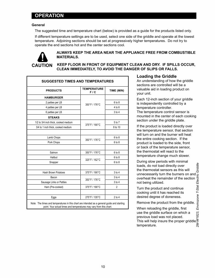
GeneralThe suggested time and temperature chart (below) is provided as a guide for the products listed only. If different temperature settings are to be used, select one side of the griddle and operate at the lowest temperature. Adjoining sections should be set at progressively higher temperatures. Do not try to operate the end sections hot and the center sections cool.
ALWAYS KEEP THE AREA NEAR THE APPLIANCE FREE FROM COMBUSTIBLE MATERIALS.
KEEP FLOOR IN FRONT OF EQUIPMENT CLEAN AND DRY. IF SPILLS OCCUR, CLEAN IMMEDIATELY, TO AVOID THE DANGER OF SLIPS OR FALLS.
Loading the GriddleAn understanding of how the griddle sections are controlled will be a valuable aid in loading product on your unit.Each 12-inch section of your griddle is independently controlled by a temperature controller. The temperature control sensor is mounted in the center of each cooking section under the griddle plate.If the product is loaded directly over the temperature sensor, that section will turn on and the burner will heat the entire cooking section. If the product is loaded to the side, front or back of the temperature sensor, the thermostat will react to the temperature change much slower.During slow periods with minimal loads, do not load directly over the thermostat sensors as this will unnecessarily turn the burners on and overheat the remainder of the section not being utilized.Turn the product and continue cooking until it has reached its desired degree of doneness.Remove the product from the griddle.When reloading the griddle, first use the griddle surface on which a previous load was not placed. This will help insure the proper griddle temperature.
SUGGESTED TIMES AND TEMPERATURES
PRODUCTS TEMPERATURE F / C TIME (MIN)
HAMBURGER
350°F / 176°C2 patties per LB 6 to 84 patties per LB 4 to 66 patties per LB 3 to 4
STEAKS1/2 to 3/4 inch thick, cooked medium
375°F / 190°C5 to 7
3/4 to 1 inch thick, cooked medium 8 to 10
Lamb Chops350°F / 176°C
6 to 8Pork Chops 6 to 8
Salmon 350°F / 176°C 6 to 8Halibut
325°F / 162°C6 to 8
Snapper 6 to 8
Hash Brown Potatoes 375°F / 190°C 3 to 4Bacon
350°F / 176°C3 to 4
Sausage Links or Patties 3 to 4Ham (Pre-cooked) 375°F / 190°C 2
Eggs 275°F / 135°C 2 to 4
Note: The times and temperatures in this chart are intended as a general guide and starting point. Your actual times and temperatures may vary from this chart.
CAUTION
11
2M-W
1823
, Env
irozo
ne T
-Sta
t Ele
ctric
Grid
dle
MAINTENANCE & CLEANING
Cleaning• Always start with a cold griddle.• The stainless exterior can easily be cleaned using a good non-abrasive cleaner.• Always follow the cleaner manufacturer’s instructions when using any cleaner.• Always apply these cleaners when the griddle is cold and rub in the direction of the metal’s
grain.
Griddle Surface Care (non-chromium surfaces)It takes very little time and effort to keep the griddle attractive and performing at top efficiency. If grease is permitted to accumulate, it will form a gummy cake and then carbonize into a hard substance which is extremely difficult to remove. To prevent this condition, the following suggestions for cleanliness should be followed:
• After each use, scrape the griddle with a scraper or flexible spatula to remove excess grease and food. A waste drawer is provided for the scrapings. If there is an accumulation of burned on grease and food, the griddle should be thoroughly scoured and re-seasoned. Use pumice or griddle stone while the griddle is warm.
Do not use steel wool because of the danger of steel slivers getting into the food.
Daily CleaningEmpty the grease drawer or whenever it is 3/4 full. It is easily removed for washing.
USE CAUTION WHEN REMOVING THE RELEASE DRAWER AS IT CONTAINS HOT GREASE.
Clean the exterior of the appliance with hot water and mild detergent to maintain a gleaming appearance.Keep the griddle surface clean. After each cooking load scrape the griddle surface to remove any carbonized grease.
Weekly CleaningOnce a week or when necessary the griddle surface should be cleaned and seasoned. Use a griddle stone, griddle pad, or liquid cleaner. Rub with the grain of the metal, being careful not to scrape the splash guard.A mild detergent with water or one of the many commercial griddle cleaners may be used.Be sure to rinse thoroughly and coat the cooking surface with a thin film of oil to prevent rusting.Season the griddle plate after each cleaning.
WARNING

12
2M-W
1823
, Env
irozo
ne T
-Sta
t Ele
ctric
Grid
dle
MAINTENANCE & CLEANING
GRIDDLE CARE (CHROME SURFACES)(Chrome surface griddles are marked with “CHS” at the end of the model number designation on the nameplate.) It takes very little time and effort to keep this Industrial Chrome griddle surface sparkling clean and performing at top efficiency. DO NOT allow grease to accumulate as it will carbonize and become difficult to remove. To prevent this condition, the following cleaning suggestions should be followed:
1. Remove excess oil and food regularly with a 4” (100mm) wide razor sharp type scraper and wipe surface with a damp cloth if desired.
2. Following the scraping, for end of the day cleaning, a damp cloth and a non-silicated,non-abrasive, non-chlorinated cleaner such as Bon-Ami may be used to wipe surface clean, followed by wiping with clean wet cloth.
3. Follow daily cleaning steps for Non-Chrome Surfaces.Note: All Chrome griddles come with: a scrapper (p/n: 2P-50100-15) Bon-Ami Cleaner (p/n: 2P-50100-16) and a 20” Palmyra Brush (p/n: 2P-50100-17).
ON CROME SURFACES:1. Never use pumice, griddle stones, or abrasives on the surface.2. Never strike the griddle surface with a sharp instrument or spatula edge.3. Never use steel wool.4. Never use commercial liquid grill cleaner on the griddle surface.5. Abusing the surface voids the warranty.
KEEP WATER AND SOLUTIONS OUT OF CONTROLS. NEVER SPRAY OR HOSE CONTROL CONSOLE.
MOST CLEANERS ARE HARMFUL TO THE SKIN, EYES, MUCOUS MEMBRANES AND CLOTHING. PRECAUTIONS SHOULD BE TAKEN TO WEAR RUBBER GLOVES, GOGGLES OR FACE SHIELD AND PROTECTIVE CLOTHING. CAREFULLY READ THE WARNING AND FOLLOW THE DIRECTIONS ON THE LABEL OF THE CLEANER TO BE USED.
NOTICE: Never leave a chlorine sanitizer in contact with stainless steel surfaces longer than 10 minutes. Longer contact can cause corrosion.
CAUTION
CAUTION
13
2M-W
1823
, Env
irozo
ne T
-Sta
t Ele
ctric
Grid
dle
WARNING
CAUTION
TROUBLESHOOTING
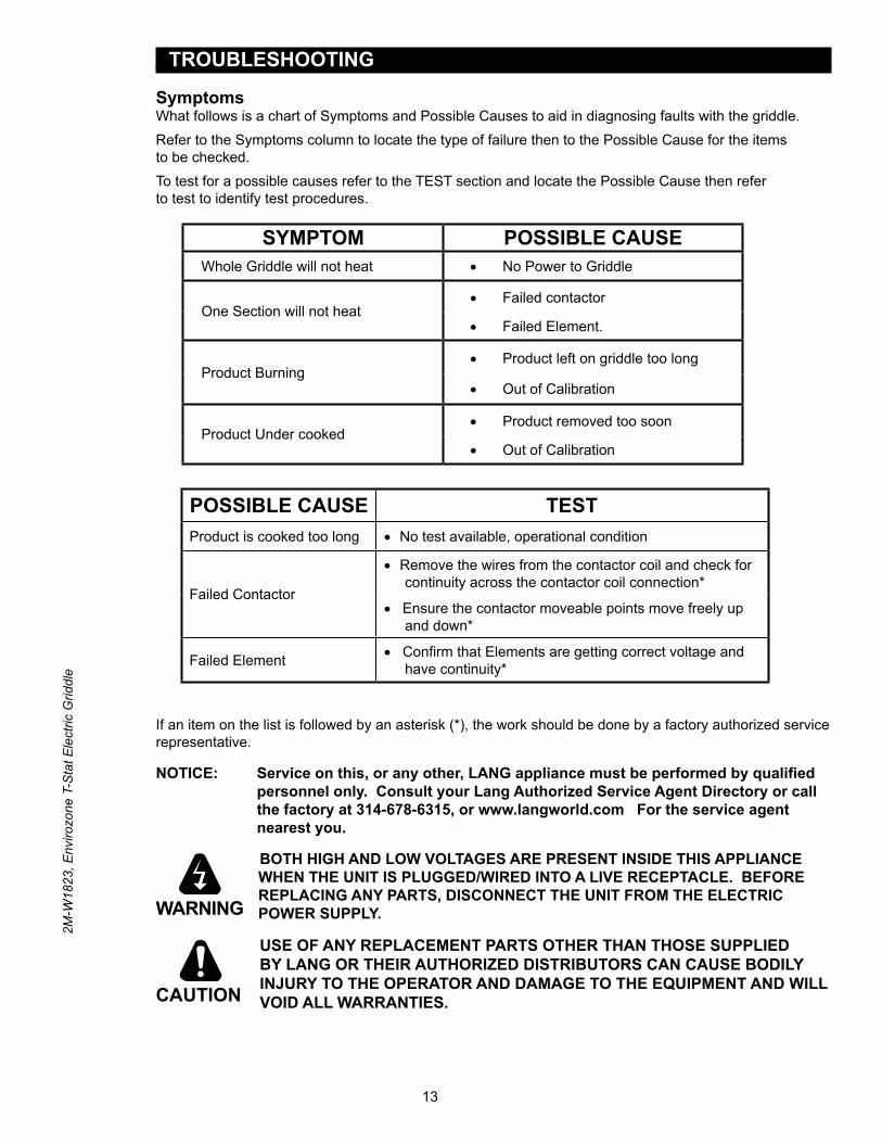
SymptomsWhat follows is a chart of Symptoms and Possible Causes to aid in diagnosing faults with the griddle.Refer to the Symptoms column to locate the type of failure then to the Possible Cause for the items to be checked.To test for a possible causes refer to the TEST section and locate the Possible Cause then refer to test to identify test procedures.
If an item on the list is followed by an asterisk (*), the work should be done by a factory authorized service representative.
NOTICE: Service on this, or any other, LANG appliance must be performed by qualified personnel only. Consult your Lang Authorized Service Agent Directory or call the factory at 314-678-6315, or www.langworld.com For the service agent nearest you.
BOTH HIGH AND LOW VOLTAGES ARE PRESENT INSIDE THIS APPLIANCE WHEN THE UNIT IS PLUGGED/WIRED INTO A LIVE RECEPTACLE. BEFORE REPLACING ANY PARTS, DISCONNECT THE UNIT FROM THE ELECTRIC POWER SUPPLY.
USE OF ANY REPLACEMENT PARTS OTHER THAN THOSE SUPPLIED BY LANG OR THEIR AUTHORIZED DISTRIBUTORS CAN CAUSE BODILY INJURY TO THE OPERATOR AND DAMAGE TO THE EQUIPMENT AND WILL VOID ALL WARRANTIES.
SYMPTOM POSSIBLE CAUSEWhole Griddle will not heat • No Power to Griddle
One Section will not heat• Failed contactor
• Failed Element.
Product Burning• Product left on griddle too long
• Out of Calibration
Product Under cooked• Product removed too soon
• Out of Calibration
POSSIBLE CAUSE TESTProduct is cooked too long • No test available, operational condition
Failed Contactor
• Remove the wires from the contactor coil and check for continuity across the contactor coil connection*
• Ensure the contactor moveable points move freely up and down*
Failed Element • Confirm that Elements are getting correct voltage and have continuity*
14
2M-W
1823
, Env
irozo
ne T
-Sta
t Ele
ctric
Grid
dle
15
31
1
148T136T
124T
L1 L2 L34
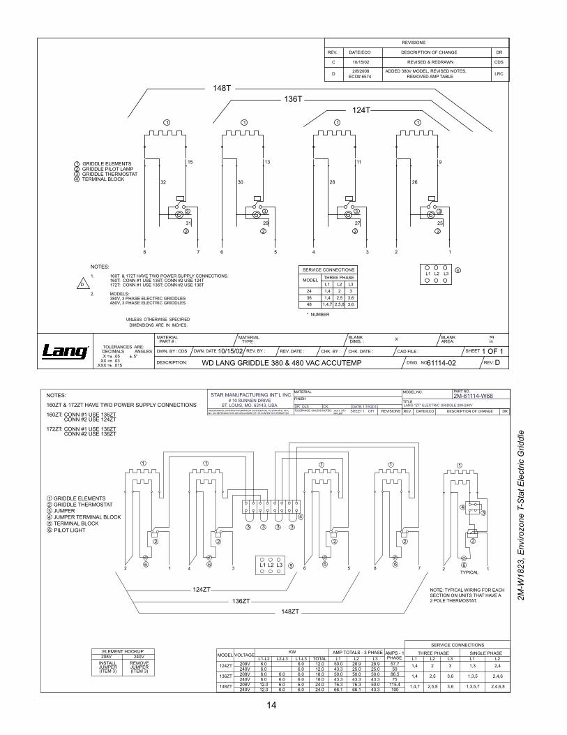
NOTES:
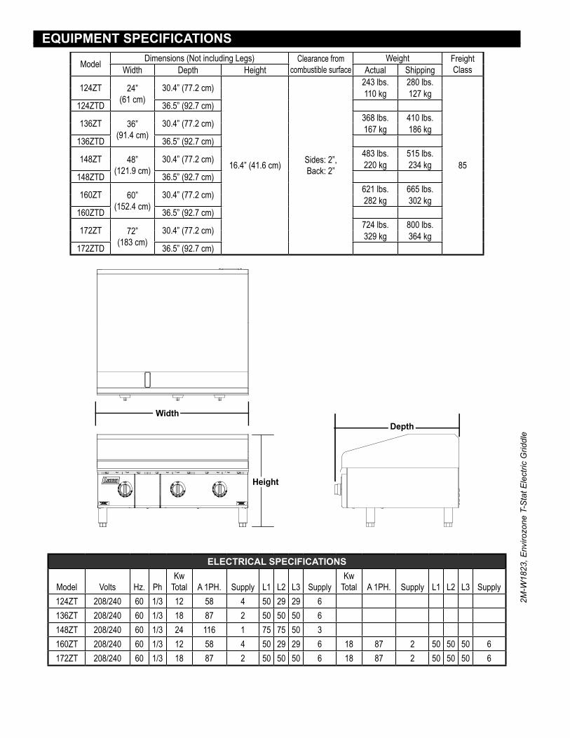
160T & 172T HAVE TWO POWER SUPPLY CONNECTIONS.1.160T: CONN #1 USE 136T; CONN #2 USE 124T172T: CONN #1 USE 136T; CONN #2 USE 136T
MODELS:2.380V, 3 PHASE ELECTRIC GRIDDLES480V, 3 PHASE ELECTRIC GRIDDLES
1 GRIDDLE ELEMENTS2 GRIDDLE PILOT LAMP3 GRIDDLE THERMOSTAT4 TERMINAL BLOCK
3
2
32
8 7
***
* *
6
*
5
*
13
3
292
30
* * *
1 1 1
4
*
3
*
11
3
272
28
* * *
2
*
1
*
9
3
252
26
* * *
WD LANG GRIDDLE 380 & 480 VAC ACCUTEMP D61114-02
D
CDS 10/15/02
DWG. NO:
SHEETDWN. DATE :DWN. BY : CHK. BY :
UNLESS OTHERWISE SPECIFIEDDIMENSIONS ARE IN INCHES.
TOLERANCES ARE:DECIMALS ANGLES
.X = ± .05 ± .5°
.XXX = ± .015
BLANK DIMS. :
DESCRIPTION:
MATERIAL PART # :
.XX = ± .03 REV:
1 OF 1
MATERIAL TYPE :
BLANK AREA:X
CAD FILE :
sqin
CHK. DATE :REV. BY : REV. DATE :
REVISIONS
REV. DATE/ECO DESCRIPTION OF CHANGE DR
C 10/15/02 REVISED & REDRAWN CDS
D 2/8/2008ECO# 6574
ADDED 380V MODEL, REVISED NOTES, REMOVED AMP TABLE LRC
SERVICE CONNECTIONS
MODEL
243648
2,51,41,4,7 2,5,8
1,4L22
3,63,6
L33
L1THREE PHASE
* NUMBER
GRIDDLE ELEMENTS1234
GRIDDLE THERMOSTATJUMPERJUMPER TERMINAL BLOCKTERMINAL BLOCK5PILOT LIGHT6
5L3L2L1
NOTES:
160ZT & 172ZT HAVE TWO POWER SUPPLY CONNECTIONS
160ZT: CONN #1 USE 136ZT CONN #2 USE 124ZT
172ZT: CONN #1 USE 136ZT CONN #2 USE 136ZT
2
3
2
3
2
3
2
3
4
1111
148ZT
136ZT
124ZT
2 1 4 3 6 5 8 7
THIS DRAWING CONTAINS INFORMATION CONFIDENTIAL TO STAR MFG. INT'L INC. NO REPRODUCTION OR DISCLOSURE OF ITS CONTENTS IS PERMITTED
TOLERANCE: UNLESS NOTED: .xxx ± .015 ANGLES ± 1°
REVISIONS
PART NO.MODEL NO.
TITLE
MATERIAL
FINISH
12
1
43
2
NOTE: TYPICAL WIRING FOR EACHSECTION ON UNITS THAT HAVE A2 POLE THERMOSTAT.
TYPICAL
6666 6
REV. DATE/ECO DESCRIPTION OF CHANGE DR
ELEMENT HOOKUP208V 240V
INSTALL JUMPER(ITEM 3)
REMOVE JUMPER(ITEM 3)
MODEL VOLTAGEKW AMP TOTALS - 3 PHASE AMPS - 1
PHASE
SERVICE CONNECTIONS
THREE PHASE SINGLE PHASEL1-L2 L2-L3 L1-L3 TOTAL L1 L2 L3 L1 L2 L3 L1 L2
124ZT 208V 6.0 6.0 12.0 50.0 28.9 28.9 57.7 1,4 2 3 1,3 2,4240V 6.0 6.0 12.0 43.3 25.0 25.0 50
136ZT 208V 6.0 6.0 6.0 18.0 50.0 50.0 50.0 86.5 1,4 2,5 3,6 1,3,5 2,4,6240V 6.0 6.0 6.0 18.0 43.3 43.3 43.3 75
148ZT 208V 12.0 6.0 6.0 24.0 76.3 76.3 50.0 115.4 1,4,7 2,5,8 3,6 1,3,5,7 2,4,6,8240V 12.0 6.0 6.0 24.0 66.1 66.1 43.3 100
DR: CK. DATE:
2M-61114-W68LANG "ZT" ELECTRIC GRIDDLE 208-240V1/19/2012DJS
STAR MANUFACTURING INT’L INC.# 10 SUNNEN DRIVE
ST. LOUIS, MO. 63143, USASHEET OF1 1

15
2M-W
1823
, Env
irozo
ne T
-Sta
t Ele
ctric
Grid
dle
SK2583, Rev. A 6/28/13
Model: Electric EnviroZone Griddle124ZT thru 172ZT
1
2 3
4
7
8
9
11
12 1027
2829
26
15
13
14
15
16
17
19
20
21
22
23
24
25
18
54
6
16
2M-W
1823
, Env
irozo
ne T
-Sta
t Ele
ctric
Grid
dle
PARTS LIST February 11, 2015, Rev C
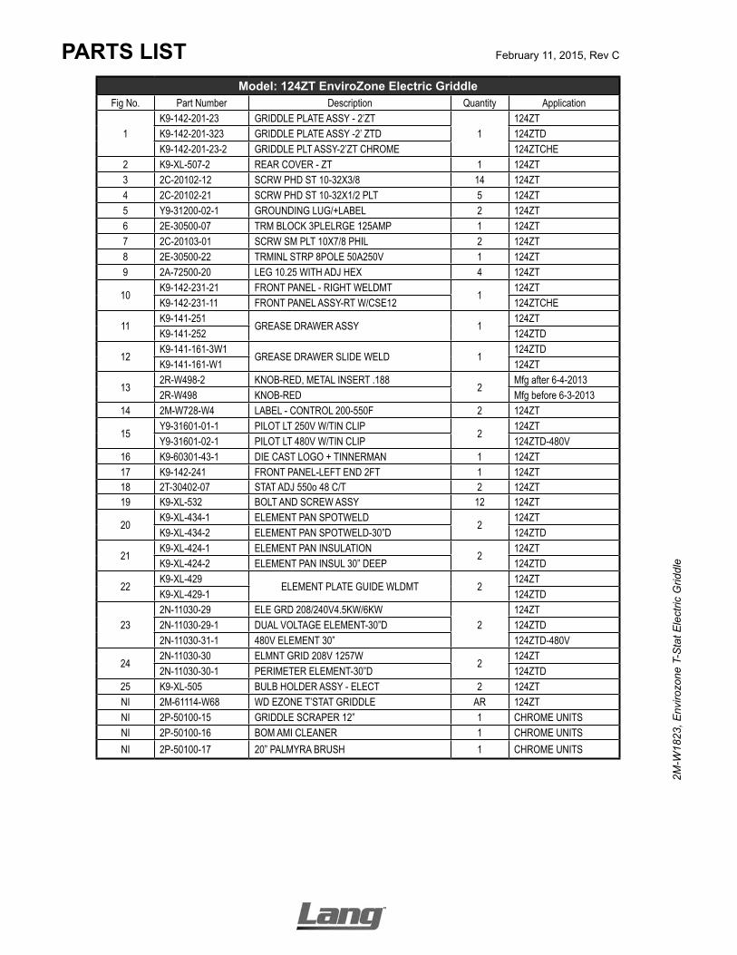
Model: 124ZT EnviroZone Electric GriddleFig No. Part Number Description Quantity Application
1K9-142-201-23 GRIDDLE PLATE ASSY - 2’ZT
1124ZT
K9-142-201-323 GRIDDLE PLATE ASSY -2’ ZTD 124ZTDK9-142-201-23-2 GRIDDLE PLT ASSY-2’ZT CHROME 124ZTCHE
2 K9-XL-507-2 REAR COVER - ZT 1 124ZT3 2C-20102-12 SCRW PHD ST 10-32X3/8 14 124ZT4 2C-20102-21 SCRW PHD ST 10-32X1/2 PLT 5 124ZT5 Y9-31200-02-1 GROUNDING LUG/+LABEL 2 124ZT6 2E-30500-07 TRM BLOCK 3PLELRGE 125AMP 1 124ZT7 2C-20103-01 SCRW SM PLT 10X7/8 PHIL 2 124ZT8 2E-30500-22 TRMINL STRP 8POLE 50A250V 1 124ZT9 2A-72500-20 LEG 10.25 WITH ADJ HEX 4 124ZT
10K9-142-231-21 FRONT PANEL - RIGHT WELDMT
1124ZT
K9-142-231-11 FRONT PANEL ASSY-RT W/CSE12 124ZTCHE
11K9-141-251
GREASE DRAWER ASSY 1124ZT
K9-141-252 124ZTD
12K9-141-161-3W1
GREASE DRAWER SLIDE WELD 1124ZTD
K9-141-161-W1 124ZT
132R-W498-2 KNOB-RED, METAL INSERT .188
2Mfg after 6-4-2013
2R-W498 KNOB-RED Mfg before 6-3-201314 2M-W728-W4 LABEL - CONTROL 200-550F 2 124ZT
15Y9-31601-01-1 PILOT LT 250V W/TIN CLIP
2124ZT
Y9-31601-02-1 PILOT LT 480V W/TIN CLIP 124ZTD-480V16 K9-60301-43-1 DIE CAST LOGO + TINNERMAN 1 124ZT17 K9-142-241 FRONT PANEL-LEFT END 2FT 1 124ZT18 2T-30402-07 STAT ADJ 550o 48 C/T 2 124ZT19 K9-XL-532 BOLT AND SCREW ASSY 12 124ZT
20K9-XL-434-1 ELEMENT PAN SPOTWELD
2124ZT
K9-XL-434-2 ELEMENT PAN SPOTWELD-30”D 124ZTD
21K9-XL-424-1 ELEMENT PAN INSULATION
2124ZT
K9-XL-424-2 ELEMENT PAN INSUL 30” DEEP 124ZTD
22K9-XL-429
ELEMENT PLATE GUIDE WLDMT 2124ZT
K9-XL-429-1 124ZTD
232N-11030-29 ELE GRD 208/240V4.5KW/6KW
2124ZT
2N-11030-29-1 DUAL VOLTAGE ELEMENT-30”D 124ZTD2N-11030-31-1 480V ELEMENT 30” 124ZTD-480V
242N-11030-30 ELMNT GRID 208V 1257W
2124ZT
2N-11030-30-1 PERIMETER ELEMENT-30”D 124ZTD25 K9-XL-505 BULB HOLDER ASSY - ELECT 2 124ZTNI 2M-61114-W68 WD EZONE T’STAT GRIDDLE AR 124ZTNI 2P-50100-15 GRIDDLE SCRAPER 12” 1 CHROME UNITSNI 2P-50100-16 BOM AMI CLEANER 1 CHROME UNITSNI 2P-50100-17 20” PALMYRA BRUSH 1 CHROME UNITS

17
2M-W
1823
, Env
irozo
ne T
-Sta
t Ele
ctric
Grid
dle
PARTS LIST February 11, 2015, Rev C
Model: 136ZT EnviroZone Electric GriddleFig No. Part Number Description Quantity Application
1
K9-142-201-33 GRIDDLE PLATE ASSY - 3’ZT
1
136ZTK9-142-201-33-1 GRID PLATE ASSY-3’ ZT 136ZTCK9-142-201-333 GRIDDLE PLATE ASSY -3’ ELEC 136ZTDK9-142-201-3330 GRIDDLE PL ASY 3’ EL DP CH 136ZTDCK9-142-201-33-3 GRIDDLE PL. ASSY-3” ZT W. 136ZTHE
2 K9-XL-507-2 REAR COVER - ZT 1 136ZT3 2C-20102-12 SCRW PHD ST 10-32X3/8 19 136ZT4 2C-20102-21 SCRW PHD ST 10-32X1/2 PLT 5 136ZT5 Y9-31200-02-1 GROUNDING LUG/+LABEL 2 136ZT6 2E-30500-07 TRM BLOCK 3PLELRGE 125AMP 1 136ZT7 2C-20103-01 SCRW SM PLT 10X7/8 PHIL 2 136ZT8 2E-30500-22 TRMINL STRP 8POLE 50A250V 1 136ZT9 2A-72500-20 LEG 10.25 WITH ADJ HEX 4 136ZT
10K9-142-245
FRONT PANEL - RIGHT END 1136ZT
K9-142-245-13 136ZTHE-380V
11K9-141-251
GREASE DRAWER ASSY 1136ZT
K9-142-251 136ZTD
12K9-141-161-W1
GREASE DRAWER SLIDE WELD 1136ZT
K9-142-161-W1 136ZTD
132R-W498-2 KNOB-RED, METAL INSERT .188
3Mfg after 6-4-2013
2R-W498 KNOB-RED Mfg before 6-3-201314 2M-W728-W4 LABEL - CONTROL 200-550F 3 136ZT
15Y9-31601-01-1 PILOT LT 250V W/TIN CLIP
3 136ZT4 136ZTHE
Y9-31601-02-1 PILOT LT 480V W/TIN CLIP 3 136ZT-480V,136ZTHE-380V16 K9-60301-43-1 DIE CAST LOGO + TINNERMAN 1 136ZT17 K9-142-241 FRONT PANEL-LEFT END 2FT 1 136ZT18 2T-30402-07 STAT ADJ 550o 48 C/T 3 136ZT19 K9-XL-532 BOLT AND SCREW ASSY 18 136ZT
20K9-XL-434-1
ELEMENT PAN SPOTWELD 3136ZT
K9-XL-434-2 136ZTD
21K9-XL-424-1 ELEMENT PAN INSULATION
3136ZT
K9-XL-424-2 ELEMENT PAN INUSL 30” DEEP 136ZTD
22K9-XL-429
ELEMENT PLATE GUIDE WLDMT 3136ZT
K9-XL-429-1 136ZTD
23
2N-11030-29 ELE GRD 208/240V4.5KW/6KW
3
136ZT2N-11030-29-1 DUAL VOLTAGE ELEMENT-30”D 136ZTD2N-11030-04 ELMNT GRID 380V 5991W 136ZTHE-380V2N-11030-31 ELMNT GRID 480V 5991W 136ZT-480V2N-11030-31-1 480V ELEMENT 30” 136ZTD-480V
242N-11030-30 ELMNT GRID 208V 1257W
3136ZT
2N-11030-30-1 PERIMETER ELEMENT-30”D 136ZTD25 K9-XL-505 BULB HOLDER ASSY - ELECT 3 136ZT* 2M-61114-W68 WD EZONE T’STAT GRIDDLE AR 136ZT
26 2E-Z12020 SWITCH-TOGGLE 2P ST 1 136ZTHE27 Z1-70-07-0343 SWITCH GUARD 1 136ZTHE28 2M-12-07-0038 LABEL ON & OFF 1 136ZTHE29 2I-05-07-0013 BOOT SWITCH 1 136ZTHENI 2P-50100-15 GRIDDLE SCRAPER 12” 1 CHROME UNITSNI 2P-50100-16 BOM AMI CLEANER 1 CHROME UNITSNI 2P-50100-17 20” PALMYRA BRUSH 1 CHROME UNITS
18
2M-W
1823
, Env
irozo
ne T
-Sta
t Ele
ctric
Grid
dle
PARTS LIST February 11, 2015, Rev C
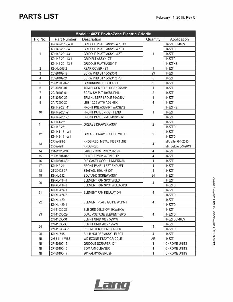
Model: 148ZT EnviroZone Electric GriddleFig No. Part Number Description Quantity Application
1
K9-142-201-3430 GRIDDLE PLATE ASSY - 4’ZTDC
1
148ZTDC-480VK9-142-201-343 GRIDDLE PLATE ASSY - 4’ZTD 148ZTDK9-142-201-43 GRIDDLE PLATE ASSY - 4’ZT 148ZTK9-142-201-43-1 GRID PLT ASSY-4’ ZT 148ZTCK9-142-201-43-3 GRIDDLE PLATE ASSY 4’ 148ZTHE
2 K9-XL-507-2 REAR COVER - ZT 1 148ZT3 2C-20102-12 SCRW PHD ST 10-32X3/8 23 148ZT4 2C-20102-21 SCRW PHD ST 10-32X1/2 PLT 5 148ZT5 Y9-31200-02-1 GROUNDING LUG/+LABEL 2 148ZT6 2E-30500-07 TRM BLOCK 3PLELRGE 125AMP 1 148ZT7 2C-20103-01 SCRW SM PLT 10X7/8 PHIL 2 148ZT8 2E-30500-22 TRMINL STRP 8POLE 50A250V 1 148ZT9 2A-72500-20 LEG 10.25 WITH ADJ HEX 4 148ZT
10K9-142-231-11 FRONT PNL ASSY-RT W/CSE12
1148ZTHE
K9-142-231-21 FRONT PANEL - RIGHT END 148ZTK9-142-231-61 FRONT PANEL - MID ASSY - 6” 148ZT
11K9-141-251
GREASE DRAWER ASSY 2148ZT
K9-142-251 148ZTD
12K9-141-161-W1
GREASE DRAWER SLIDE WELD 2148ZT
K9-142-161-W1 148ZTD
132R-W498-2 KNOB-RED, METAL INSERT .188
4Mfg after 6-4-2013
2R-W498 KNOB-RED Mfg before 6-3-201314 2M-W728-W4 LABEL - CONTROL 200-550F 4 148ZT15 Y9-31601-01-1 PILOT LT 250V W/TIN CLIP 4 148ZT16 K9-60301-43-1 DIE CAST LOGO + TINNERMAN 1 148ZT17 K9-142-241 FRONT PANEL-LEFT END 2FT 1 148ZT18 2T-30402-07 STAT ADJ 550o 48 C/T 4 148ZT19 K9-XL-532 BOLT AND SCREW ASSY 24 148ZT
20K9-XL-434-1 ELEMENT PAN SPOTWELD
4148ZT
K9-XL-434-2 ELEMENT PAN SPOTWELD-30”D 148ZTD
21K9-XL-424-1
ELEMENT PAN INSULATION 4148ZT
K9-XL-424-2 148ZTD
22K9-XL-429
ELEMENT PLATE GUIDE WLDMT 4148ZT
K9-XL-429-1 148ZTD
232N-11030-29 ELE GRD 208/240V4.5KW/6KW
4148ZT
2N-11030-29-1 DUAL VOLTAGE ELEMENT-30”D 148ZTD2N-11030-31 ELMNT GRID 480V 5991W 148ZTDC-480V
242N-11030-30 ELMNT GRID 208V 1257W
4148ZT
2N-11030-30-1 PERIMETER ELEMENT-30”D 148ZTD25 K9-XL-505 BULB HOLDER ASSY - ELECT 4 148ZTNI 2M-61114-W68 WD EZONE T’STAT GRIDDLE AR 148ZTNI 2P-50100-15 GRIDDLE SCRAPER 12” 1 CHROME UNITSNI 2P-50100-16 BOM AMI CLEANER 1 CHROME UNITSNI 2P-50100-17 20” PALMYRA BRUSH 1 CHROME UNITS

19
2M-W
1823
, Env
irozo
ne T
-Sta
t Ele
ctric
Grid
dle
PARTS LIST February 11, 2015, Rev C
Model: 160ZT EnviroZone Electric GriddleFig No. Part Number Description Quantity Application
1
K9-142-201-353 GRIDDLE PLATE ASSY-5’ ZTD
1
160ZTDK9-142-201-53 GRIDDLE PLATE ASSY - 5’ZT 160ZTK9-142-201-53-3 GRIDDLE PLATE ASSY 5’ ZT 160ZTHEK9-142-201-53-1 GRIDDLE PLATE ASSY 5’ ZT, CHROME 160TZTC
2 K9-XL-507-2 REAR COVER - ZT 2 160ZT3 2C-20102-12 SCRW PHD ST 10-32X3/8 22 160ZT4 2C-20102-21 SCRW PHD ST 10-32X1/2 PLT 10 160ZT5 Y9-31200-02-1 GROUNDING LUG/+LABEL 4 160ZT6 2E-30500-07 TRM BLOCK 3PLELRGE 125AMP 2 160ZT7 2C-20103-01 SCRW SM PLT 10X7/8 PHIL 4 160ZT8 2E-30500-22 TRMINL STRP 8POLE 50A250V 2 160ZT9 2A-72500-20 LEG 10.25 WITH ADJ HEX 4 160ZT
10K9-142-231-21 FRONT PANEL - RIGHT END
1160ZT
K9-142-231-51 FRONT PANEL - MIDDLE ASSY 5 160ZTK9-142-231-11 FRONT PANEL ASSY-RT W/CSE12 160THE-480V
11K9-141-251
GREASE DRAWER ASSY 2160ZT, 160THE
K9-142-251 160ZTD
12K9-141-161-3W1 GREASE DRAWER SLIDE WELD
2160ZTD
K9-141-161-W1 GREASE DRAWER SLIDE WELD 160ZT
132R-W498-2 KNOB-RED, METAL INSERT .188
5Mfg after 6-4-2013
2R-W498 KNOB-RED Mfg before 6-3-201314 2M-W728-W4 LABEL - CONTROL 200-550F 5 160ZT
15Y9-31601-01-1 PILOT LT 250V W/TIN CLIP
5160ZT
Y9-31601-02-1 PILOT LT 480V W/TIN CLIP 160ZTHE-480V16 K9-60301-43-1 DIE CAST LOGO + TINNERMAN 1 160ZT17 K9-142-241 FRONT PANEL - MID ASSY - 5” 1 160ZT18 2T-30402-07 STAT ADJ 550o 48 C/T 5 160ZT19 K9-XL-532 BOLT AND SCREW ASSY 30 160ZT
20K9-XL-434-1 ELEMENT PAN SPOTWELD
5160ZT
K9-XL-434-2 ELEMENT PAN SPOTWELD-30”D 160ZTD
21K9-XL-424-1 ELEMENT PAN INSULATION
5160ZT
K9-XL-424-2 ELEMENT PAN INSUL 30”DEEP 160ZTD
22K9-XL-429 ELEMENT PLATE GUIDE WLDMT
5160ZT
K9-XL-429-1 ELEMENT PLATE GUIDE WELD 160ZTD
232N-11030-29 ELE GRD 208/240V4.5KW/6KW
5160ZT
2N-11030-29-1 DUAL VOLTAGE ELEMENT-30”D 160ZTD
242N-11030-30 ELMNT GRID 208V 1257W
5160ZT
2N-11030-30-1 PERIMETER ELEMENT-30”D 160ZTD2N-11030-31 ELMNT GRID 480V 5991W 160THE-480V
25 K9-XL-505 BULB HOLDER ASSY - ELECT 5 160ZTNI 2M-61114-W68 WD EZONE T’STAT GRIDDLE AR 160ZTNI 2P-50100-15 GRIDDLE SCRAPER 12” 1 CHROME UNITSNI 2P-50100-16 BOM AMI CLEANER 1 CHROME UNITSNI 2P-50100-17 20” PALMYRA BRUSH 1 CHROME UNITS
PARTS LIST February 11, 2015, Rev C
STAR INTERNATIONAL HOLDINGS INC. COMPANYStar - Holman - Lang - Wells - Bloomfield - Toastmaster
10 Sunnen Drive, St. Louis, MO 63143 U.S.A.(314) 678-6303
www.star-mfg.com
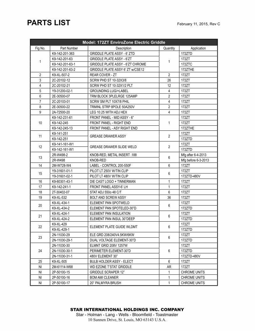
Model: 172ZT EnviroZone Electric GriddleFig No. Part Number Description Quantity Application
1
K9-142-201-363 GRIDDLE PLATE ASSY - 6’ ZTD
1
172ZTDK9-142-201-63 GRIDDLE PLATE ASSY - 6’ZT 172ZTK9-142-201-63-1 GRIDDLE PLATE ASSY - 6’ZT CHROME 172ZTCK9-142-201-63-2 GRIDDLE PLATE ASSY 6’ ZT w/CSE12 172ZTHE
2 K9-XL-507-2 REAR COVER - ZT 2 172ZT3 2C-20102-12 SCRW PHD ST 10-32X3/8 26 172ZT4 2C-20102-21 SCRW PHD ST 10-32X1/2 PLT 12 172ZT5 Y9-31200-02-1 GROUNDING LUG/+LABEL 4 172ZT6 2E-30500-07 TRM BLOCK 3PLELRGE 125AMP 2 172ZT7 2C-20103-01 SCRW SM PLT 10X7/8 PHIL 4 172ZT8 2E-30500-22 TRMINL STRP 8POLE 50A250V 2 172ZT9 2A-72500-20 LEG 10.25 WITH ADJ HEX 4 172ZT
10K9-142-231-61 FRONT PANEL - MID ASSY - 6”
1172ZT
K9-142-245 FRONT PANEL - RIGHT END 172ZTK9-142-245-13 FRONT PANEL - ASY RIGHT END 172ZTHE
11K9-141-251
GREASE DRAWER ASSY 2172ZT
K9-142-251 172ZTD
12K9-141-161-W1
GREASE DRAWER SLIDE WELD 2172ZT
K9-142-161-W1 172ZTD
132R-W498-2 KNOB-RED, METAL INSERT .188
6Mfg after 6-4-2013
2R-W498 KNOB-RED Mfg before 6-3-201314 2M-W728-W4 LABEL - CONTROL 200-550F 6 172ZT
15Y9-31601-01-1 PILOT LT 250V W/TIN CLIP
6172ZT
Y9-31601-02-1 PILOT LT 480V W/TIN CLIP 172ZTD-480V16 K9-60301-43-1 DIE CAST LOGO + TINNERMAN 1 172ZT17 K9-142-241-1 FRONT PANEL ASSY-6’ LH 1 172ZT18 2T-30402-07 STAT ADJ 550o 48 C/T 6 172ZT19 K9-XL-532 BOLT AND SCREW ASSY 36 172ZT
20K9-XL-434-1 ELEMENT PAN SPOTWELD
6172ZT
K9-XL-434-2 ELEMENT PAN SPOTELED-30”D 172ZTD
21K9-XL-424-1 ELEMENT PAN INSULATION
6172ZT
K9-XL-424-2 ELEMENT PAN INSUL 30”DEEP 172ZTD
22K9-XL-429
ELEMENT PLATE GUIDE WLDMT 6172ZT
K9-XL-429-1 172ZTD
232N-11030-29 ELE GRD 208/240V4.5KW/6KW
6172ZT
2N-11030-29-1 DUAL VOLTAGE ELEMENT-30”D 172ZTD
242N-11030-30 ELMNT GRID 208V 1257W
6172ZT
2N-11030-30-1 PERIMETER ELEMENT-30”D 172ZTD2N-11030-31-1 480V ELEMENT 30” 172ZTD-480V
25 K9-XL-505 BULB HOLDER ASSY - ELECT 6 172ZTNI 2M-61114-W68 WD EZONE T’STAT GRIDDLE AR 172ZTNI 2P-50100-15 GRIDDLE SCRAPER 12” 1 CHROME UNITSNI 2P-50100-16 BOM AMI CLEANER 1 CHROME UNITSNI 2P-50100-17 20” PALMYRA BRUSH 1 CHROME UNITS
Related Documents