Entry Task: Watch weekly video on district youtube channel. Agenda: Review Chapter 45 Presentation Material. Read Chapter 45 – Welding Symbols, pgs 675 – 689. Complete Ch 45 Workbook, pgs 167 – 168. Answer all Questions. Complete Chapter 45 Assessment. Due by 6/5. Turn in assessment via screenshot attachment or google form to: [email protected] Student Target: I will learn about Welding Symbols with 80% accuracy. Expected Discourse Level for this Lesson: N/A. Exit Task: Turn in assessment by due date listed above. For the week of: 6/1/20 – 6/5/20 Welding 4th Period

Welcome message from author
This document is posted to help you gain knowledge. Please leave a comment to let me know what you think about it! Share it to your friends and learn new things together.
Transcript

Entry Task: Watch weekly video on district youtube channel.
Agenda: Review Chapter 45 Presentation Material. Read Chapter 45 – Welding Symbols, pgs 675 – 689.Complete Ch 45 Workbook, pgs 167 – 168. Answer all Questions.Complete Chapter 45 Assessment. Due by 6/5.
Turn in assessment via screenshot attachment or google form to: [email protected]
Student Target: I will learn about Welding Symbols with 80% accuracy.
Expected Discourse Level for this Lesson: N/A.
Exit Task: Turn in assessment by due date listed above.
For the week of: 6/1/20 – 6/5/20
Welding 4th Period

Premium PowerPoint® Presentation
Chapter 45
Welding Symbols • Combining Weld Symbols •
Nondestructive Examination Symbols
Welding Symbols

Chapter 45 — Welding Symbols
© 2015 by American Technical PublishersAll rights reserved
Objectives
• Explain the general features of a welding symbol.
• Explain weld symbol combinations for the different
types of welds.
• Describe the use of nondestructive examination
symbols.

Chapter 45 — Welding Symbols
© 2015 by American Technical PublishersAll rights reserved
A welding symbol is a graphical representation of the
specifications for producing a welded joint.

Chapter 45 — Welding Symbols
© 2015 by American Technical PublishersAll rights reserved
A weld symbol is a graphic symbol connected to the
reference line of a welding symbol specifying the weld type.

Chapter 45 — Welding Symbols
© 2015 by American Technical PublishersAll rights reserved
The location of the weld
symbol determines where
the weld is made.
Chapter 45 — Welding Symbols
© 2015 by American Technical PublishersAll rights reserved
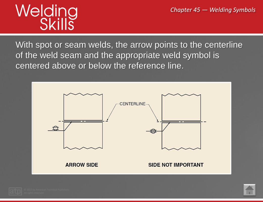
With spot or seam welds, the arrow points to the centerline
of the weld seam and the appropriate weld symbol is
centered above or below the reference line.

Chapter 45 — Welding Symbols
© 2015 by American Technical PublishersAll rights reserved
In symbols showing
beveled joints, the arrow
points with a definite break
toward the part to be
beveled.

Chapter 45 — Welding Symbols
© 2015 by American Technical PublishersAll rights reserved
Fillet, single-bevel-groove,
J-groove, and flare-bevel-
groove weld symbols
appear with the
perpendicular leg to the left
of the weld symbol.

Chapter 45 — Welding Symbols
© 2015 by American Technical PublishersAll rights reserved
During fabrication of a
product, it may be
necessary to perform more
than one operation on a
joint. In such cases, both
the type of joint preparation
and the type of weld can
be combined in the weld
symbol.

Chapter 45 — Welding Symbols
© 2015 by American Technical PublishersAll rights reserved
A fillet weld is represented
by a right-angle triangle.
The weld toe is formed by
the junction between the
surface of the weld and the
base metal.

Chapter 45 — Welding Symbols
© 2015 by American Technical PublishersAll rights reserved
The length and pitch of
intermittent fillet weld
segments are shown to the
right of the weld symbol
separated by a dash. The
first number indicates the
length of each weld
segment and the second
number represents the
pitch (center-to-center
spacing) of adjacent weld
segments on one side of
the joint.

Chapter 45 — Welding Symbols
© 2015 by American Technical PublishersAll rights reserved
Common types of groove welds are single-square-groove
welds, double-square-groove welds, single-V-groove welds,
double-V-groove welds, single-bevel-groove welds, and
double-bevel-groove welds.
Chapter 45 — Welding Symbols
© 2015 by American Technical PublishersAll rights reserved
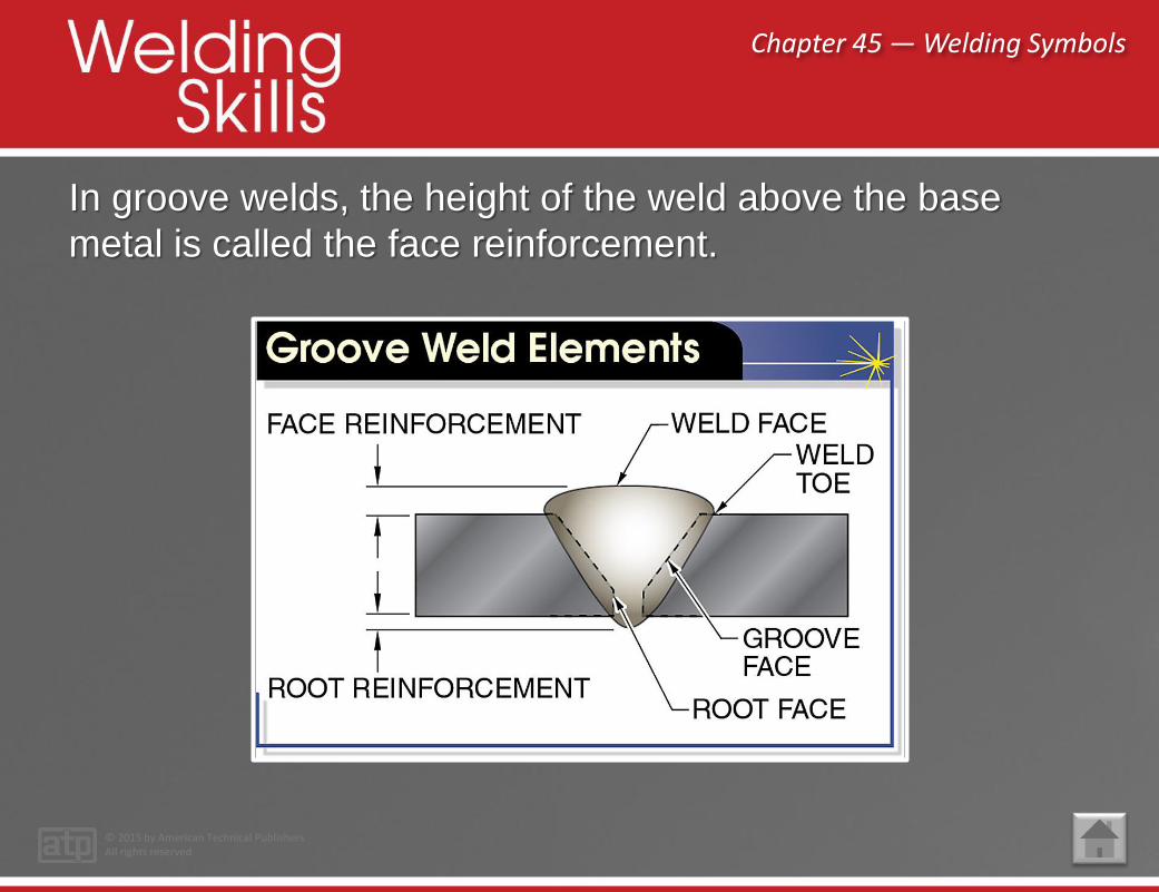
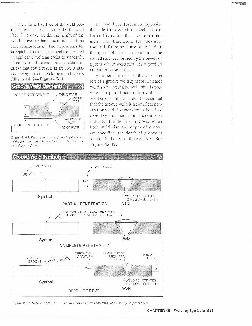
In groove welds, the height of the weld above the base
metal is called the face reinforcement.
Chapter 45 — Welding Symbols
© 2015 by American Technical PublishersAll rights reserved
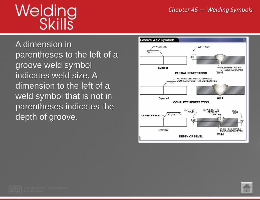
A dimension in
parentheses to the left of a
groove weld symbol
indicates weld size. A
dimension to the left of a
weld symbol that is not in
parentheses indicates the
depth of groove.
Chapter 45 — Welding Symbols
© 2015 by American Technical PublishersAll rights reserved
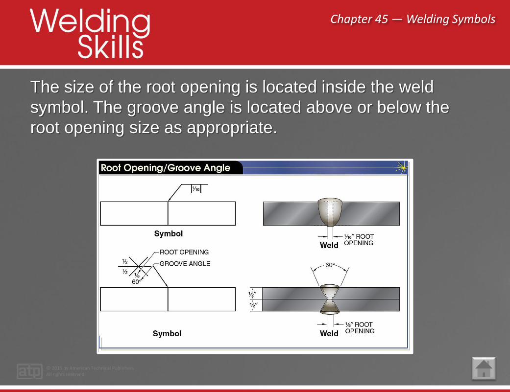
The size of the root opening is located inside the weld
symbol. The groove angle is located above or below the
root opening size as appropriate.
Chapter 45 — Welding Symbols
© 2015 by American Technical PublishersAll rights reserved
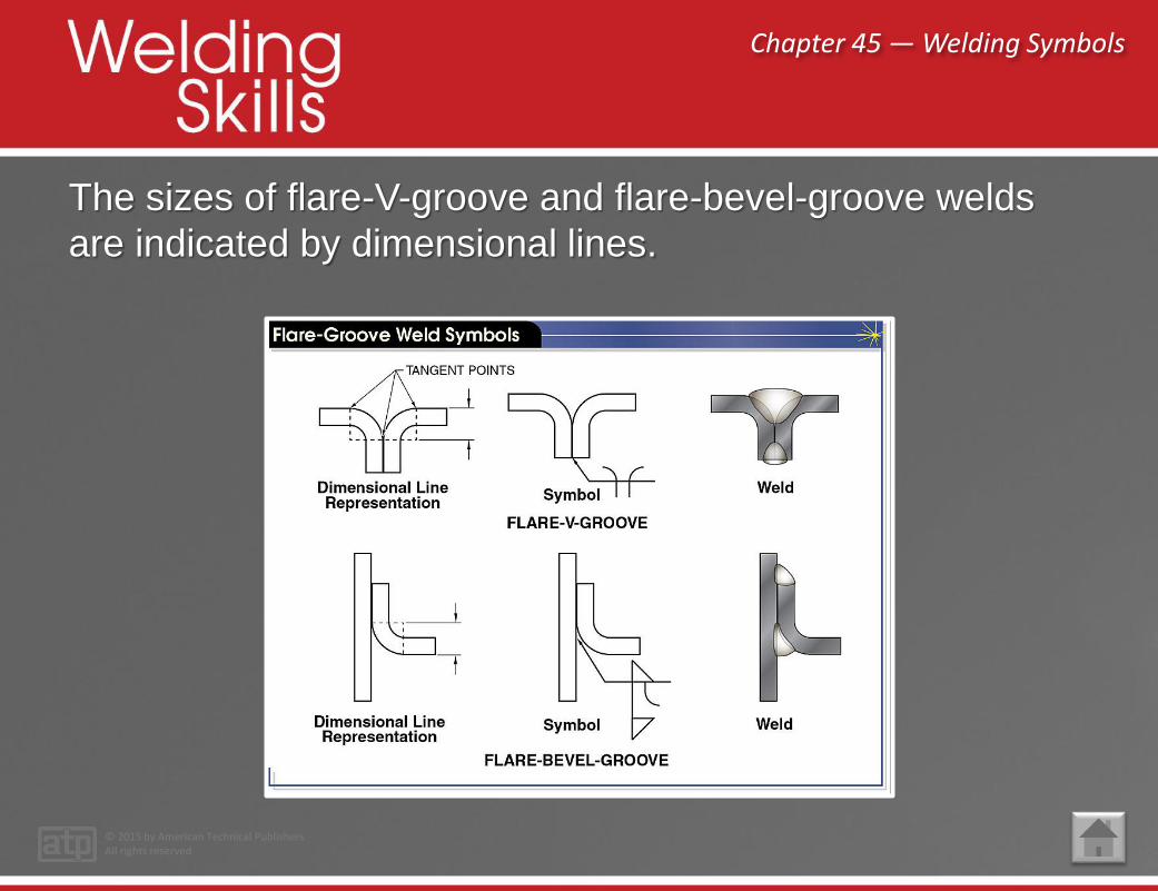
The sizes of flare-V-groove and flare-bevel-groove welds
are indicated by dimensional lines.

Chapter 45 — Welding Symbols
© 2015 by American Technical PublishersAll rights reserved
The size of a plug weld is shown to the left of the plug weld
symbol and is preceded by the diameter symbol, Ø. The
depth of filling, when less than complete, is shown inside
the weld symbol. The center-to-center distance (pitch) is
shown to the right of the weld symbol.

Chapter 45 — Welding Symbols
© 2015 by American Technical PublishersAll rights reserved
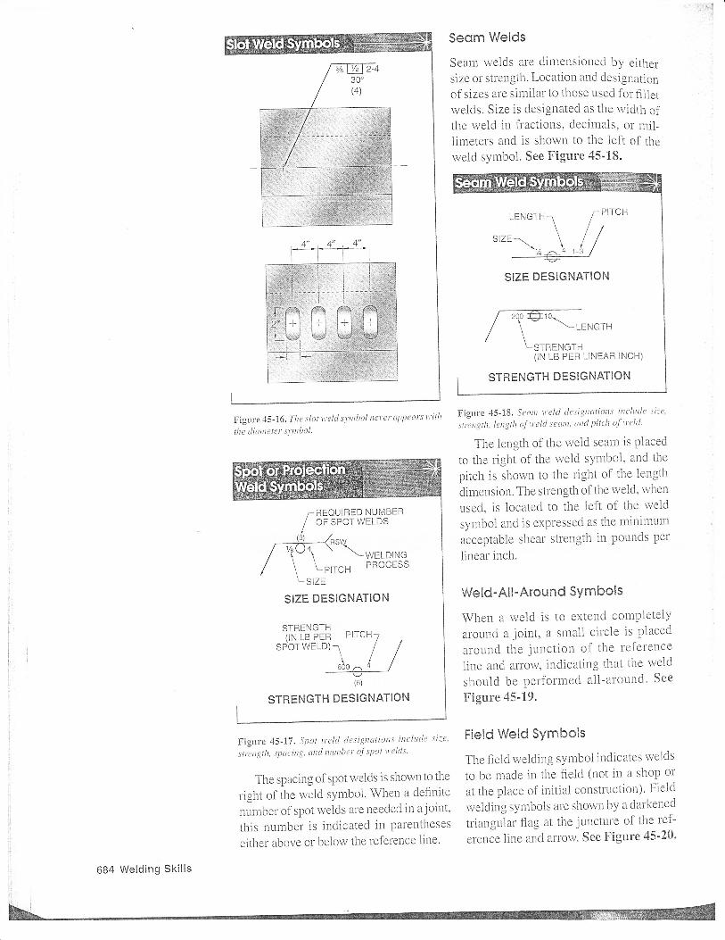
The slot weld symbol is
similar to the plug weld
symbol except that it does
not include a diameter
symbol.
Chapter 45 — Welding Symbols
© 2015 by American Technical PublishersAll rights reserved
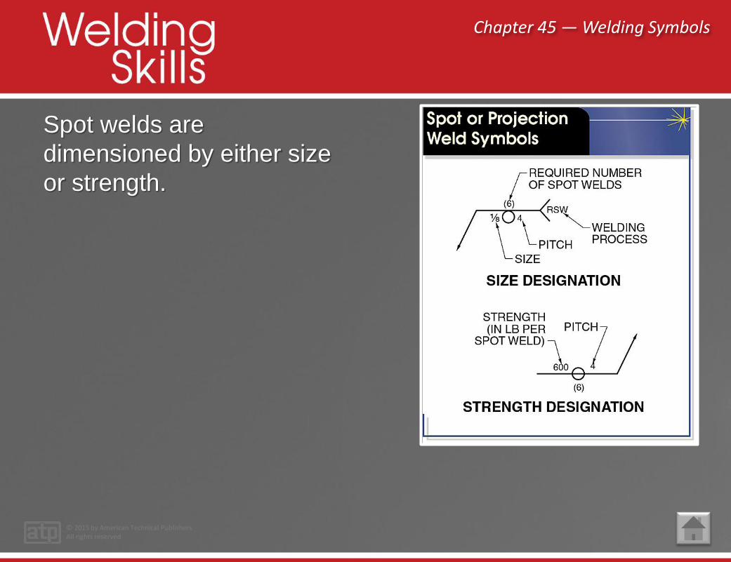
Spot welds are
dimensioned by either size
or strength.

Chapter 45 — Welding Symbols
© 2015 by American Technical PublishersAll rights reserved
Seam welds are
dimensioned by either size
or strength.

Chapter 45 — Welding Symbols
© 2015 by American Technical PublishersAll rights reserved
A small circle appears
where the arrow connects
the reference line to denote
“weld-all-around.”
Chapter 45 — Welding Symbols
© 2015 by American Technical PublishersAll rights reserved
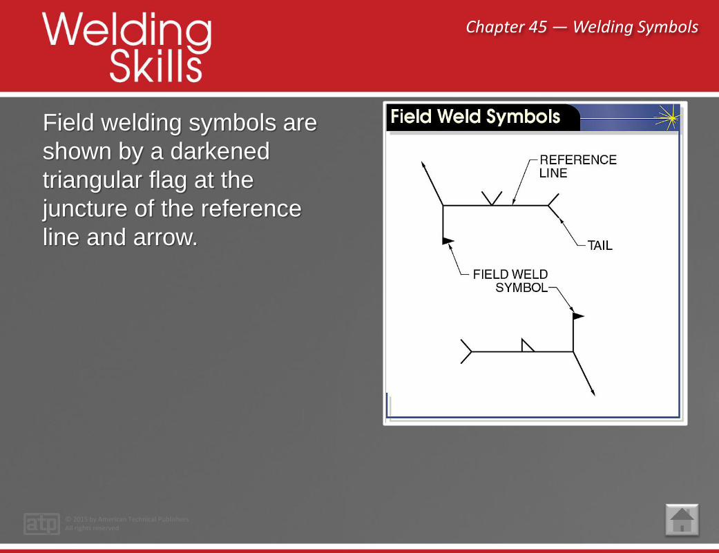
Field welding symbols are
shown by a darkened
triangular flag at the
juncture of the reference
line and arrow.
Chapter 45 — Welding Symbols
© 2015 by American Technical PublishersAll rights reserved
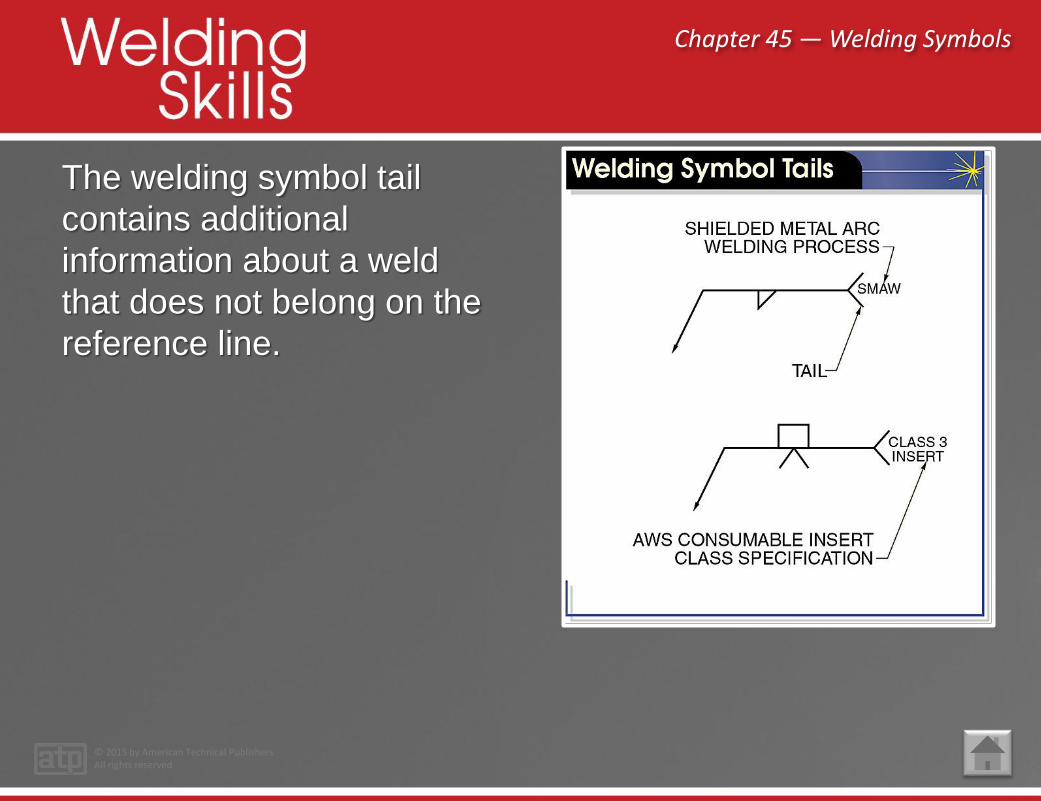
The welding symbol tail
contains additional
information about a weld
that does not belong on the
reference line.

Chapter 45 — Welding Symbols
© 2015 by American Technical PublishersAll rights reserved
When bead contour is important, a special flat, concave, or
convex contour symbol is added to the welding symbol.

Chapter 45 — Welding Symbols
© 2015 by American Technical PublishersAll rights reserved
The back or backing weld
symbol is included opposite
the weld symbol with a
note included in the tail.
When multiple reference
lines are used, back and
backing welds are shown in
the appropriate sequence.

Chapter 45 — Welding Symbols
© 2015 by American Technical PublishersAll rights reserved
A solid semicircle on the reference line opposite the weld
symbol indicates complete penetration or melt-through.

Chapter 45 — Welding Symbols
© 2015 by American Technical PublishersAll rights reserved
Welds whose surfaces must be built up by single- or
multiple-pass welding are denoted by a surfacing weld
symbol.

Chapter 45 — Welding Symbols
© 2015 by American Technical PublishersAll rights reserved
Points to Remember
• A welding symbol is a graphical representation of the
specifications for producing a welded joint.
• Instructions regarding the type of weld are indicated
either above or below the reference line.
• The arrow side of the joint is the side of the joint to
which the arrow points. The other side is the side of
the joint opposite the arrow side.…Continued on next slide

Chapter 45 — Welding Symbols
© 2015 by American Technical PublishersAll rights reserved
Points to Remember (continued)
• When more than one operation is required on a joint,
a symbol is shown for each operation.
• Welds to be made in the field are shown by a
darkened triangular flag at the juncture of the
reference line and arrow.
• Nondestructive examination (NDE) symbols are
symbols that specify examination methods and
requirements to verify weld quality.

Chapter 45 — Welding Symbols
© 2015 by American Technical PublishersAll rights reserved
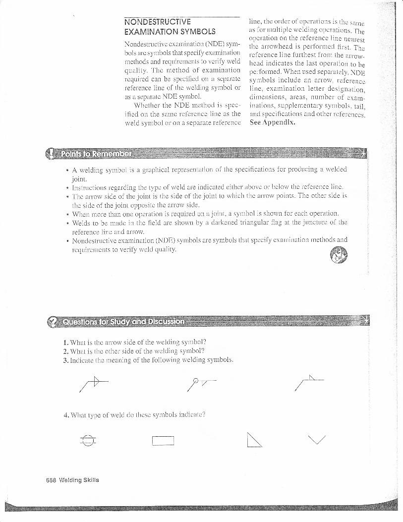
Questions for Study and Discussion
1. What is the arrow side of the welding symbol?
2. What is the other side of the welding symbol?
3. Indicate the meaning of the following welding
symbols.
…Continued on next slide
Chapter 45 — Welding Symbols
© 2015 by American Technical PublishersAll rights reserved
Questions for Study
and Discussion (continued)
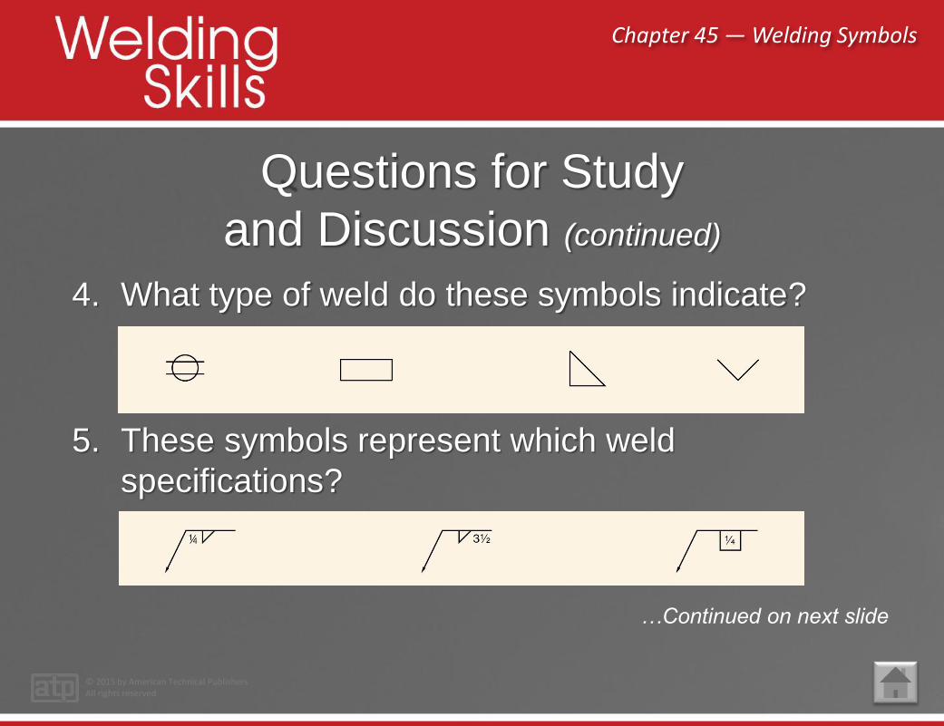
4. What type of weld do these symbols indicate?
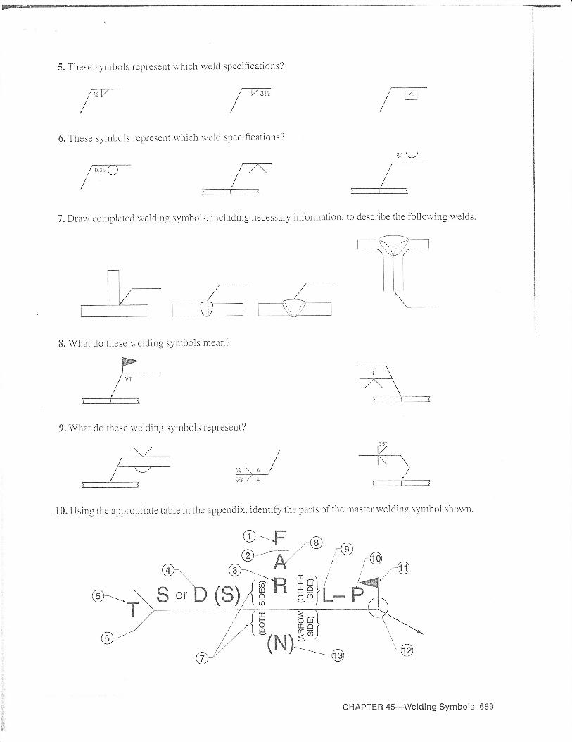
5. These symbols represent which weld
specifications?
…Continued on next slide

Chapter 45 — Welding Symbols
© 2015 by American Technical PublishersAll rights reserved
Questions for Study
and Discussion (continued)
6. These symbols represent which weld specifications?
7. Draw completed welding symbols, including necessary information, to describe the following welds.
…Continued on next slide
Chapter 45 — Welding Symbols
© 2015 by American Technical PublishersAll rights reserved
Questions for Study
and Discussion (continued)
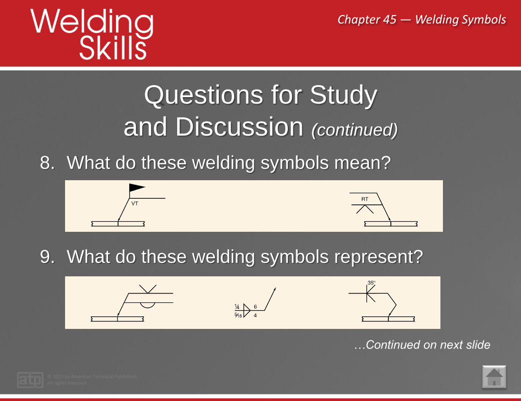
8. What do these welding symbols mean?
9. What do these welding symbols represent?
…Continued on next slide
Chapter 45 — Welding Symbols
© 2015 by American Technical PublishersAll rights reserved
Questions for Study
and Discussion (continued)
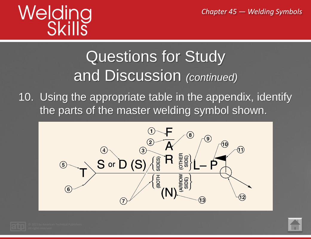
10. Using the appropriate table in the appendix, identify
the parts of the master welding symbol shown.


Related Documents