http://www.3com.com/ Enterprise OS Software Version 11.3 Release Notes 3Com provides a CD-ROM that includes all Enterprise OS software version 11.2 software manuals plus software version 11.3 features updates and version 11.3 new installation and upgrade manuals. To obtain a hardcopy version of the 11.3 documentation, order part number 3C6460S. You can order the documentation CD-ROM using part number 3C6461S. Additionally, all documentation for Enterprise OS software version 11.3 is located on the 3Com website: http://infodeli.3com.com/infodeli/tools/bridrout/index.htm Part No. 86-0611-000 Published May 1999

Welcome message from author
This document is posted to help you gain knowledge. Please leave a comment to let me know what you think about it! Share it to your friends and learn new things together.
Transcript
Enterprise OS Software Version 11.3 Release Notes
http://www.3com.com/
3Com provides a CD-ROM that includes all Enterprise OS software version 11.2 software manuals plus software version 11.3 features updates and version 11.3 new installation and upgrade manuals. To obtain a hardcopy version of the 11.3 documentation, order part number 3C6460S.
You can order the documentation CD-ROM using part number 3C6461S.
Additionally, all documentation for Enterprise OS software version 11.3 is located on the 3Com website:
http://infodeli.3com.com/infodeli/tools/bridrout/index.htm
Part No. 86-0611-000Published May 1999
3Com Corporation5400 Bayfront Plaza Santa Clara, California 95052-8145
Copyright © 3Com Corporation, 1999. All rights reserved. No part of this documentation may be reproduced in any form or by any means or used to make any derivative work (such as translation, transformation, or adaptation) without permission from 3Com Corporation.
3Com Corporation reserves the right to revise this documentation and to make changes in content from time to time without obligation on the part of 3Com Corporation to provide notification of such revision or change.
3Com Corporation provides this documentation without warranty of any kind, either implied or expressed, including, but not limited to, the implied warranties of merchantability and fitness for a particular purpose. 3Com may make improvements or changes in the product(s) and/or the program(s) described in this documentation at any time.
UNITED STATES GOVERNMENT LEGENDS:If you are a United States government agency, then this documentation and the software described herein are provided to you subject to the following restricted rights:
For units of the Department of Defense:Restricted Rights Legend: Use, duplication, or disclosure by the Government is subject to restrictions as set forth in subparagraph (c) (1) (ii) for Restricted Rights in Technical Data and Computer Software Clause at 48 C.F.R. 52.227-7013. 3Com Corporation, 5400 Bayfront Plaza, Santa Clara, California 95052-8145.
For civilian agencies:Restricted Rights Legend: Use, reproduction, or disclosure is subject to restrictions set forth in subparagraph (a) through (d) of the Commercial Computer Software – Restricted Rights Clause at 48 C.F.R. 52.227-19 and the limitations set forth in 3Com Corporation’s standard commercial agreement for the software. Unpublished rights reserved under the copyright laws of the United States.
If there is any software on removable media described in this documentation, it is furnished under a license agreement included with the product as a separate document, in the hard copy documentation, or on the removable media in a directory file named LICENSE.TXT. If you are unable to locate a copy, please contact 3Com and a copy will be provided to you.
The software you have received may contain strong data encryption code that cannot be exported outside of the U.S. or Canada. You agree that you will not export/reexport, either physically or electronically, the encryption software or accompanying documentation (or copies thereof) or any products utilizing the encryption software or such documentation without obtaining written authorization from the U.S. Department of Commerce.
Unless otherwise indicated, 3Com registered trademarks are registered in the United States and may or may not be registered in other countries.
3Com, AccessBuilder, Boundary Routing, NETBuilder, NETBuilder II, OfficeConnect, SuperStack, and Transcend are registered trademarks and Edge Server, PathBuilder, and Total Control are trademarks of 3Com Corporation.
IBM, AS/400, SNA, and LAN Net Manager are registered trademarks of International Business Machines Corporation. Advanced Peer-to-Peer Networking and APPN are trademarks of International Business Machines Corporation. DECnet is a registered trademark of Digital Equipment Corporation. AppleTalk is a registered trademark of Apple Computer, Inc. NetWare is a registered trademark of Novell, Inc. RealPlayer is a trademark of Real Networks. UNIX is a registered trademark in the United States and other countries, licensed exclusively through X/Open Company, Ltd. VINES is a registered trademark of Banyan Systems. SunOS is a trademark of Sun Microsystems, Inc. XNS is a trademark of Xerox Corporation.
Other brand and product names may be registered trademarks or trademarks of their respective holders.
CONTENTS
ENTERPRISE OS SOFTWARE VERSION 11.3 RELEASE NOTES
Encryption Packages Notice 9Supported Platforms 10Platforms Not Supported 10New Features and Feature Enhancements 11
IPSec Enhancements 11Improved L2TP Tunneling Performance & LAC Support 11RADIUS Server Support 11RSVP Proxy 11VRRP for Token Ring 12MPOA Client 12ISDN Call-back using CLI (Calling Line Identifier) or Caller ID 12Upgrade Utilities, Upgrade Link, and Upgrade Manager 13Web Link Statistics 13RMON Action on Event Extensions 13WAN Packet Tracing 14Transcend Secure VPN Manager 14
11.3 Software Packages 15NETBuilder II 15SuperStack II SI 18SuperStack II Token Ring 21OfficeConnect 23PathBuilder S5xx Series Switch 28
Upgrade Management Utilities 31Downloading Upgrade Management Utilities 31UNIX Files 31Windows Files 31Executing profile.bat 32Version 11.3 Upgrade Management Utilities 32Upgrading to 11.3 Utilities with Transcend Upgrade Manager 32Transcend Enterprise Manager 32
Upgrade Management Notes 33bcmdiagnose Error Message 33SuperStack II NETBuilder Token Ring Upgrades 33bcmdiagnose and HP-UX 33bcmfdinteg 33
33File Conversion Considerations 34Upgrading From Release 8.3 or Earlier 34Upgrade Link and Netscape Browser Scroll Bars 34Upgrade Link Window Resizing 34
IBM Protocols and Services Notes 35APPN 35APPN Connections to 3174 through Token Ring 35APPN CP-CP Sessions and SNA Boundary Routing 35APPN CP-CP Sessions on Parallel TGs 35APPN DLUr Connections to 3174 Systems 35BSC and Leased Lines 35Boundary Routing and NetView Service Point 35Configuring BSC and NCPs 36DLSw Circuit Balancing 36DLSw and CONNectUsage Parameter Default Change 36DLSw Prioritization 36DLSw and IBM Boundary Routing in Large Networks 36Front-End Processor/Frame Relay Access for LLC2 Traffic 37HPR and ISR Configurations 37IBM Boundary Routing Topology Disaster Recovery 37IBM-Related Services in Token Ring 38LAN Network Manager with NETBuilder II Systems 39LLC2 Frames and PPP 40Maximum BSC Line Speed 40SHDLC Half-Duplex Mode 40SDLC 40SDLC Adjacent Link Stations for APPN 40Source Route Transparent Bridging Gateway (SRTG) Interoperability 40SDLC Ports and NetView Service Point 40UI Response Time With Large SDLC configuration 40VTAM Program Temporary Fixes 40
ATM Services Notes 41ATM Emulated LANs 41ATM LAN Emulation Clients and Large 802.3 Frames 41ATM Connection Table 41Deleting ATM Neighbors 41Source-Route Transparent Gateway 41
WAN Protocols and Services Notes 41ACCM Not Configurable 41Asynch Tunnelling on Serial Ports 41Automatic Line Detection 41Auto Start-up Does Not Include Async 42Bandwidth-on-Demand Timer Precedence 42Baud Rates for WAN Ports in DCE Mode 42BSC Cabling and Clocking 42Changing the Transfer Mode Parameter Default Value 42
Compression Requirements 42Dial Idle Timer 43Disaster Recovery on Ports Without Leased Lines 43DTR Modems 43Dynamic Paths 43Frame Relay Congestion Control 43History-Based Compression Negotiation Failure 43History Compression Not Allowed With Async PPP 43Multilink PPP Configurations 43SPID Wizard Detection Errors 44STP AutoMode Does Not Select the Right Mode 44Supported Modems 44
Routing Protocols and Services Notes 44BGP Configuration Files 44CPU Utilization with XNS Protocol 45IPX to Non-IPX Configuration Error 45IPX Routing, Route Receive and Route Advertisement Policies 45Managing IP Address Assignment 45NAT Service - Many to One Outbound Translation 45NAT Service - TCP/UDP Port Mappings 45OSPF Route Advertisement 45RouteDiscovery 45VRRP Configuration 45
Network Management System and Services Notes 45ASCII Boot 45Boot Cycle Continuous Loop 46BootP Server and Autostartup 46Bootptab File 46Capturing Commands to boot.cfg File 46Change Configuration and Diagnostic Menu 46CPU Utilization Statistic 46File System Error 46Firmware Configuration 46Firmware Update 47Multiple Paths to BootP Server 47Remote Access Default Change 47Scheduler RunOnBootFail Completion 47V.25bis Modem Setup 47Web Link Documentation Path 47Web Link Login Support 47Zmodem Time Out 47
VPN Protocols and Services Notes 48ACE Security Server 48Total Control Security and Accounting Server Availability 48Microsoft MPPE Patches and Updates 48PPTP Tunnel Security Validation 48Windows NT MS-CHAP Authentication 49
Platform Notes 49
Approved DRAM SIMMs 49Supported PC Flash Memory Cards 49Line Error Reporting on PathBuilder S5xx Series Switch Statistics Display 49T3 Bandwidth Limitation 49MBRI Ownership During Board Swapping 49Multiport MBRI Module SNMP Management 49Token Ring+ Modules 50Token Ring Auto Start-up 50
22 CONFIGURING IPSEC
Configuring IPSec 53Creating Manual Policies 53Configuring Manual Security Policies 54Configuring Dynamic-Key Security Policies 56Enabling IPSec 58
How IPSec Works 58Policies 58Encapsulation Security Payload 58Authentication Header 59
Sample Configurations 59Creating a Manual Security Policy in Transport Mode 60Manual Key: Setting up a VPN PPTP Tunnel 60Manual Key: Creating a Fully Meshed Topology Between Three Routers 63Dynamic Key: Creating a Fully Meshed Topology Between Three Routers 65Dynamic Key: Hub and Spoke Topology Between Three Routers 68Dynamic Key: Hub and Spoke Topology Between Three Routers (Intranet/Extranet) 70
9 CONFIGURING RSVPWhat Is RSVP? 77RSVP Configuration Example 78RSVP Proxy Sender and Receiver 78
Proxy Sender: Unicast Destination and One Sender Port 78Proxy Receiver: Unicast Destination and One Sender Port 79Proxy Sender: Multicast Destination with a Range of Sender Ports 79Proxy Receiver: Multicast Destination with a Range of Sender Ports 79Sample RSVP Configuration with L2TP Tunnel 80
H STATISTICS DISPLAYS
RSVP Service 83RSVP Port Statistics 83
33 IPSEC SERVICE PARAMETERS
CONTrol 88DynamicPOLicy 88DynpolCONTrol 89
DynpolLifeTime 90DynpolMODE 90DynpolPFS 90DynpolPortList 91DynpolPRIority 91DynpolSlctrLIst 91DynpolTransLIst 91GlobalLifeTime 92GlobalPFS 92IKEProfile 92IKESecAssoc 94KeySet 94LogDest 95LogLevel 95ManualKeyInfo 96manualPOLicy 96PreSharedKey 98SelectorLIst 99TransformLIst 100
60 RSVP SERVICE PARAMETERS
CONTrol 104MaxFlowRate 104ProxyRECeiver 104ProxySENDer 105RefreshTimer 106REQuest 106RESerVation 106RSVPStatistics 106UDPEncap 106

ENTERPRISE OS SOFTWARE VERSION 11.3 RELEASE NOTES
These release notes provide information on the following topics for Enterprise OS software version 11.3:
■ Encryption Packages Notice
■ Supported Platforms
■ Platforms Not Supported
■ New Features and Feature Enhancements
■ 11.3 Software Packages
■ Upgrade Management Utilities
■ Upgrade Management Notes
■ IBM Protocols and Services Notes
■ ATM Services Notes
■ WAN Protocols and Services Notes
■ Routing Protocols and Services Notes
■ Network Management System and Services Notes
■ VPN Protocols and Services Notes
■ Platform Notes
■ Changes and additions to the following guides:
Reference for Enterprise OS Software
Using Enterprise OS Software
If you have questions about the software, the guides, or these release notes, contact 3Com or your network supplier.
For information on the command syntax used in these release notes, see “About This Guide” in Using Enterprise OS Software.
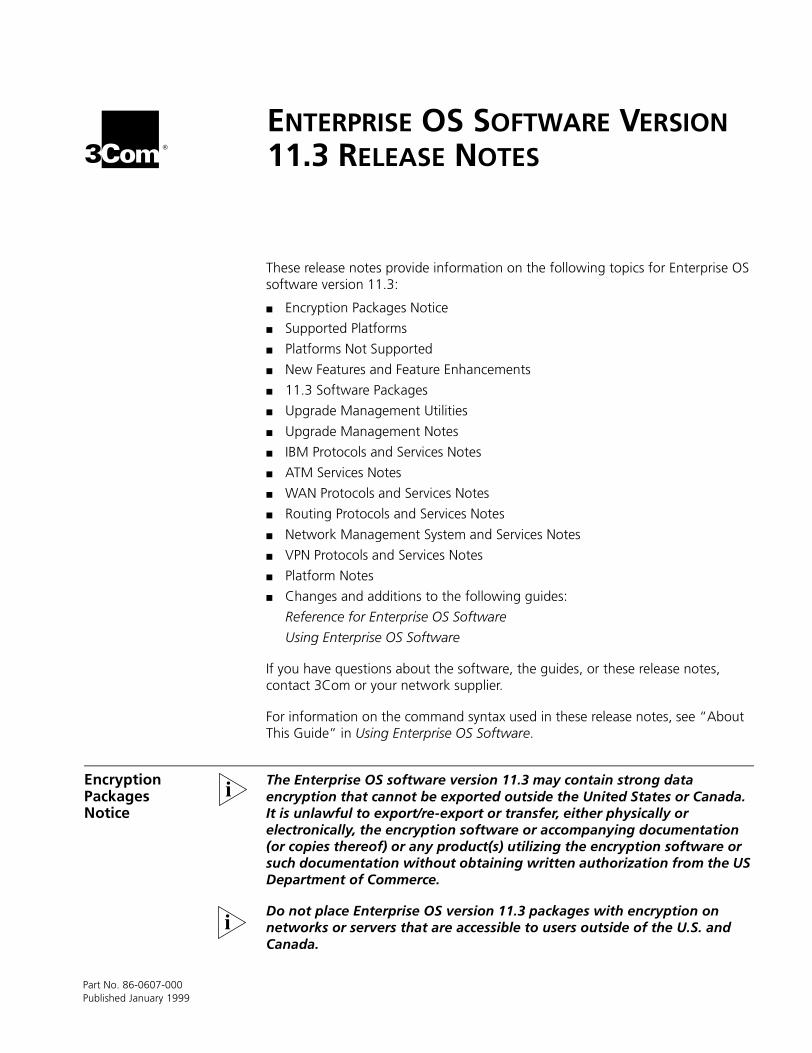
Encryption Packages Notice
The Enterprise OS software version 11.3 may contain strong data encryption that cannot be exported outside the United States or Canada. It is unlawful to export/re-export or transfer, either physically or electronically, the encryption software or accompanying documentation (or copies thereof) or any product(s) utilizing the encryption software or such documentation without obtaining written authorization from the US Department of Commerce.
Do not place Enterprise OS version 11.3 packages with encryption on networks or servers that are accessible to users outside of the U.S. and Canada.
Part No. 86-0607-000Published January 1999
10 ENTERPRISE OS SOFTWARE VERSION 11.3 RELEASE NOTES
Software packages with encryption include the following:
■ PathBuilder™ S5xx series switch
Multiprotocol Router with 40-bit Encryption (PL)
Multiprotocol Router with 56-bit Encryption (PE)
Multiprotocol Router with 128-bit Encryption (PS)
■ NETBuilder II®
Multiprotocol Router with 40-bit Encryption (DL)
Multiprotocol Router with 56-bit Encryption (DE)
Multiprotocol Router with 128-bit Encryption (DS)
■ SuperStack® II NETBuilder
IP/IPX/AT Router with 40- and 56-bit Encryption (NE) (SI model)
IP/IPX/AT Router with 128-bit Encryption (NS) (SI model)
Multiprotocol Router with 40-bit Encryption (CL) (SI model)
Multiprotocol Router with 56-bit Encryption (CE) (SI model)
Multiprotocol Router with 128-bit Encryption (CS) (SI model)
Multiprotocol Router with 56-bit Encryption (TE) (Token Ring models 327 and 527)
■ OfficeConnect® NETBuilder
IP/IPX/AT Router with 40- and 56-bit Encryption (NE)
IP/IPX/AT Router with 128-bit Encryption (NS)
Multiprotocol Router with Quick Step VPN and 56-bit Encryption (VE)
Multiprotocol Router with 56-bit Encryption (OE)
Multiprotocol Router with 128-bit Encryption (OS)
Supported Platforms Enterprise OS software version 11.3 is available for the following platforms:
■ NETBuilder II
■ SuperStack II NETBuilder® models 327 and 527
■ SuperStack II NETBuilder SI models 43x, 44x, 45x, 46x, 53x, 54x, 55x, and 56x
■ OfficeConnect NETBuilder models 11x, 12x (K and T variants),13x, and 14x (U and ST variants)
■ PathBuilder S5xx series switch models S500, S580, S593, and S594
Platforms Not Supported
The Enterprise OS software version 11.3 does not support the following bridge/routers:
■ Model 227 SuperStack II NETBuilder Router (Ethernet)
■ Model 427 SuperStack II NETBuilder Router (Ethernet, ISDN)
■ Model 120 OfficeConnect NETBuilder (FRAD)
New Features and Feature Enhancements 11
New Features and Feature Enhancements
Enterprise OS software is the operating system that runs on the NETBuilder and PathBuilder S5xx product families. Whether the software is running on a NETBuilder or PathBuilder device, the command line, web tools, and utilities are the same for all platforms.This section describes the new system/infrastructure enhancements.
IPSec Enhancements Randomized Life Time Adjustment of Key
The time that each security association (SA) rekeys is determined solely by its own expiration time. Further, each SA has its own alarm message to tell when this time is up. There are two problems with this scheme. First, the NETBuilder or PathBuilder device can schedule a rekey when a previous one could not have finished. Second, having one alarm message per SA doesn't scale as the number of SAs on a NETBuilder or PathBuilder device increases.
Starting with Enterprise OS software version 11.3, when determining the time that an SA should rekey, IPSec takes into account the times that other SAs will rekey. It tries to distribute the rekey operations evenly so that the NETBuilder or PathBuilder device will not schedule a rekey when a previously scheduled one may already be occurring. Also, it will keep only one alarm message for the whole system for SA rekeys. This new scheme is only for scheduling when the NETBuilder or PathBuilder device should initiate a rekey for an SA.
Improved L2TPTunneling Performance
& LAC Support
In Enterprise OS software version 11.3, enhancements have been made to L2TP such that L2TP tunneling performance is significantly improved. The performance improvement is more than three times that of previous releases.
Also, when the PathBuilder S5xx or NETBuilder device is used for tunnel switching, they can act as a standard-based L2TP access concentrator (LAC) for outgoing tunnels. In previous releases, the tunnel switch behaved as an L2TP network server (LNS) for outgoing tunnels and it required a second PathBuilder S5xx or NETBuilder device to terminate for the outgoing tunnels. With the LAC enhancement, the tunnel terminator hardware for outgoing tunnels can be a 3Com product or other vendor’s product.
This LAC enhancement is more useful in the service provider market where a tunnel switch may be located on one service provider’s facility (such as CLEC) and the tunnels may terminated in a different service provider’s facility (such as ISPs).
RADIUS Server Support Enterprise OS 11.3 now supports the following RADIUS servers:
■ 3Com SAS Server 6.0.8 or higher
■ FUNK Software Steel Belted RADIUS Server for Windows NT, version 02.10.05 or higher
RSVP Proxy First implemented in Enterprise OS software version 11.1, RSVP is a dynamic QoS setup protocol that enables real-time applications to reserve resources at the network nodes along the sender-to-receiver data path. RSVP is used by hosts for requesting specific qualities of service and by routers to deliver quality of service request to all nodes along the path.
12 ENTERPRISE OS SOFTWARE VERSION 11.3 RELEASE NOTES
However, “dumb” devices (such as IP telephone handsets) that are not connected to a PC or other host device cannot reserve bandwidth using RSVP. Now available in version 11.3, a proxy can be defined to solve this problem by emulating an RSVP sender or receiver on behalf of these devices.
VRRP for Token Ring The Virtual Router Redundancy Protocol is now, with Enterprise OS software version 11.3, applicable to all platforms providing for Ethernet, Fiber Distributed Data Interface (FDDI), or Token Ring. With the addition of Token Ring support, VRRP is now available for all central site topologies (except ATM). This will provide for direct feature-for-feature competition between the competition’s Hot Standby Router Protocol (HSRP) and the 3Com VRRP implementation.
All Token Ring frame types and addressing modes are supported.
■ Transparent
■ Source Route
■ Functional / Unicast address modes
VRRP is not supported on the NETBuilder II MP 6-port Ethernet module.
When operating in Unicast (non-broadcast) mode, all routers participating in the topology must reside on the same ring (all have the same associated ring number), with participating POrts on the same ring, as well.
In addition, they must all be operating in the same addressing mode (that is you cannot mix Unicast and functional addressing in the same topology).
There is an increased latency when operating in Unicast mode as the hardware will undergo a context switch to “Promiscuous” mode during the fail-over from Primary to Backup.
MPOA Client With the Enterprise OS software version 11.3, Multiprotocol Over ATM (MPOA) client support is added to the existing MPOA Server support.
Using the MPOA control messages (specifically MPOA Cache Imposition Request and Reply), the MPOA client caches the data link layer information to allow the MPOA Client to perform network layer forwarding, even though the MPOA client does not have a network protocol stack.
Using LAN Emulation (LANE), 3Com routing platforms can now provide for Virtual Circuit Connection (VCC) setup (via the Next Hop Resolution Protocol, NHRP) as well as VCC requests on behalf of legacy devices.
Support is provided for the NETBuilder II with DPE or DPE+ modules only.
ISDN Call-back using CLI(Calling Line Identifier)
or Caller ID
ISDN CLI call-back brings dial charges under control. All charged calls can be centralized to one location, allowing for negotiation of cheaper call rates and eases the task of tracking call charges. Allowing both types of call-back, namely CLI and Caller ID.
With CLI call-back, incoming calls are rejected. Call-back is based on the CLI and no charges are incurred for the calling party. The number in the CLI may be the same number as the callers or a completely different number.
New Features and Feature Enhancements 13
With caller ID call-back, incoming calls are accepted; call-back is based on PAP, CHAP, or SysCallerID identification. Some charges are incurred by the calling party as the call is accepted, but disconnected as soon as identification is complete. The Call-back number is maintained in static table.
Upgrade Utilities,Upgrade Link, andUpgrade Manager
With the upgrade utilities, you will be able to perform upgrades of your NETBuilder or PathBuilder S5xx devices from an older version of software to a newer version. The version you can upgrade to will match your version of the upgrade utilities (for example, with the Upgrade Management Utilities version 11.3, you will be able to upgrade a device running 8.x, 9.x, 10.x, 11.0, 11.1, or 11.2 to any version 9.x, 10.x, 11.0, 11.1, 11.2, or 11.3). Engineered to be reliable and simple to use, the utilities can be executed via command line, via the GUI-interface in Transcend® Upgrade Manager, or the GUI-interface in Upgrade Link, or via user-defined scripts.
Enhancements to Upgrades Utilities Version 11.3:
Previously, only a single instance of bcmdiagnose was possible. Now, multiple invocations of bcmdiagnose is supported to aid in troubleshooting connectivity between the management station and the device.
Enhancements have been made for upgrading older SuperStack II NETBuilder bridge/routers more reliably (for example, modifications to SNMP time-out values) over serial links under high traffic conditions.
Enhancements for support of upgrades in networks using Network Address Translation (NAT)–includes the ability to define the IP address of the border router used to perform the translations.
Web Link Statistics Web Link is an embedded Web-based interface for management of your Enterprise OS devices. To access Web Link, use Netscape Navigator version 4.06 or later or Internet Explorer 4.x or later.
New Web Link statistics for 11.3 include the following:
■ Interface performance
■ Physical path statistics
■ Port and Virtual port statistics (was also available with 11.2)
■ Protocol performance
■ Routing protocols
■ Total IPX packets
■ IPX packets per interface
RMON Action on EventExtensions
Especially for fault management, event reporting is useful for monitoring the network. While monitoring itself, the Enterprise OS device can be configured to perform an action when a significant or unusual event occurs. Event reporting is useful for detecting problems as soon as they arise.
For Enterprise OS version 11.3, the standard RMON Events MIB has been extended to allow a sequence of agent specific command(s) or macro(s) to be executed after
14 ENTERPRISE OS SOFTWARE VERSION 11.3 RELEASE NOTES
the normal processing of the event (i.e. after logging the event and sending a trap).
This feature should be used by an advanced administrator who has knowledge of RMON and SNMP MIB objects. Access to this feature is not available from the device’s user interface, although SNMP commands are allowed in an ASCII file that can be processed with the LoadConfig command. In the future, a GUI application will be provided, which will allow an easier means of defining events, setting thresholds, and configuring actions, as well as exposing the objects which can be monitored.
WAN Packet Tracing The tracing of WAN packets allows the administrator to look at the real-time raw data that is moving across the WAN connection. WAN packet tracing is useful in debugging problems that might occur with the WAN link, for instance when a WAN link is not coming up or under very light traffic. The new WANTrace command can be executed for PPP and Frame Relay (-POrt OWNer) types and is accessible from all Enterprise OS hardware platforms. This tool will present the raw data frames through any Telnet session for run-time analysis, or capture the data into log files. Traces can be gathered from multiple ports simultaneously by looking at concurrent Telnet sessions.
Accessible only to users with network administrator privileges, WANTrace provides different options for protocol decoding and trace conditions.
Transcend Secure VPNManager
Transcend Secure VPN Manager provides the tools to assist the administrator in capacity planning, quality of service, security and fault management of VPN tunnels. This web-based management tool collects and displays tunnel connection information, tunnel and session utilization, as well as security associations and violations on the VPN tunnels terminated by a NETBuilder bridge/router or PathBuilder S5xx series tunnel switch.
Secure VPN Manager version 2.2 enhancements include:
■ New tunnel type support has been added to support L2TP and IP-IP (aka IPsec tunnel mode). Versions 2.0 and 2.1 supported only PPTP (with IPsec enabled).
■ Enhanced device awareness will allow Secure VPN Manager to maintain a more accurate picture of the VPN network topology. Instead of running as a passive monitor of VPN tunnels, where traps could be lost (which causes Secure VPN Manager to not detect a down tunnel or session), this version of Secure VPN Manager will run as an active monitor of VPN tunnels. Secure VPN Manager actively pings known (those user-defined devices within the seedfile, or those stored in memory which were discovered) devices intermittently to determine connectivity.
■ An Alerts display has been added as the new “home” page for Secure VPN Manager to notify the administrators of significant VPN events for which action may need to be taken.
■ Overall usability enhancements have been made on the existing Secure VPN Manager displays.
Secure VPN Manager is not integrated into the Transcend application suite, but runs as a standalone application on Windows NT server. Secure VPN Manager version 2.2 is purchased separately (3C6481A).
11.3 Software Packages 15
11.3 Software Packages
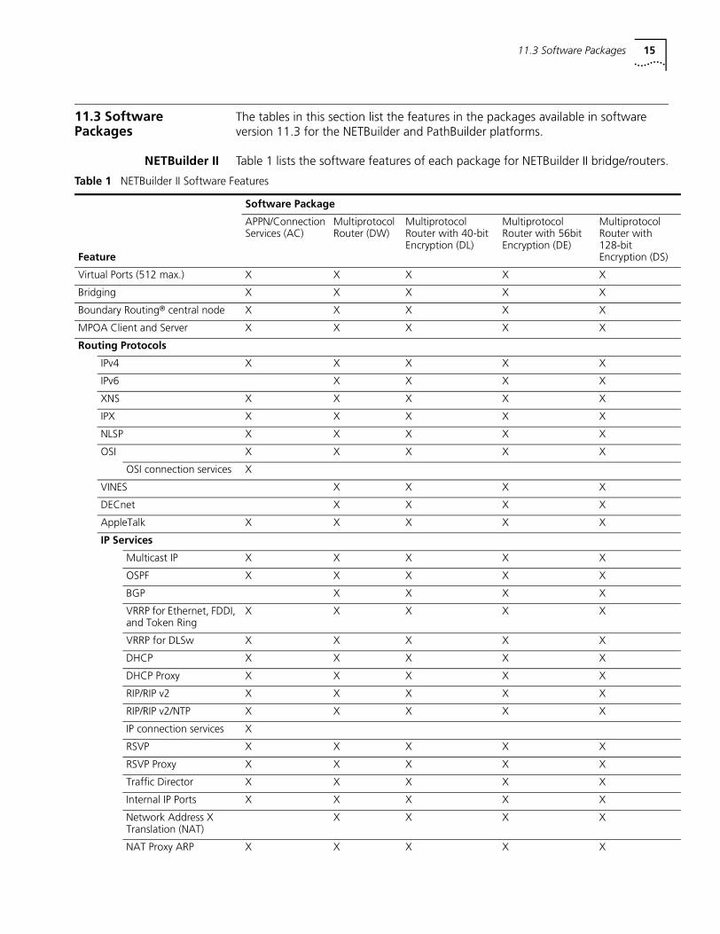
The tables in this section list the features in the packages available in software version 11.3 for the NETBuilder and PathBuilder platforms.
NETBuilder II Table 1 lists the software features of each package for NETBuilder II bridge/routers.
Table 1 NETBuilder II Software Features
Software Package
Feature
APPN/Connection Services (AC)
Multiprotocol Router (DW)
Multiprotocol Router with 40-bit Encryption (DL)
Multiprotocol Router with 56bit Encryption (DE)
Multiprotocol Router with 128-bit Encryption (DS)
Virtual Ports (512 max.) X X X X X
Bridging X X X X X
Boundary Routing® central node X X X X X
MPOA Client and Server X X X X X
Routing Protocols
IPv4 X X X X X
IPv6 X X X X
XNS X X X X X
IPX X X X X X
NLSP X X X X X
OSI X X X X X
OSI connection services X
VINES X X X X
DECnet X X X X
AppleTalk X X X X X
IP Services
Multicast IP X X X X X
OSPF X X X X X
BGP X X X X
VRRP for Ethernet, FDDI, and Token Ring
X X X X X
VRRP for DLSw X X X X X
DHCP X X X X X
DHCP Proxy X X X X X
RIP/RIP v2 X X X X X
RIP/RIP v2/NTP X X X X X
IP connection services X
RSVP X X X X X
RSVP Proxy X X X X X
Traffic Director X X X X X
Internal IP Ports X X X X X
Network Address XTranslation (NAT)
X X X X
NAT Proxy ARP X X X X X
16
Virtual Private Networks and Security
PPTP X X X X X
Tunnel Switch (PPTP & L2TP)
X X X X X
IPsec (Tunnel & Transport)
X X
IKE X X
DES Crypto X X
3DES Crypto X
RC5 Crypto X X
MPPE/RC4 Crypto X X X
LDAP Policy Engine/Client
X X X X X
MS-CHAP Authentication
X X X X
EAP Authentication X X X X
Firewall X X X X X
IP/IPX RAS X X X X
RADIUS Client X X X X
RAS Traps X X X X
Telnet Radius Authentication
X X X X X
WAN Protocols and Services
PPP (PAP, CHAP) /Multilink PPP
X X X X X
Frame Relay X X X X X
SMDS X X X X X
X.25 X X X X X
X.25 switching/tunneling X X X X X
Compression Control Protocol X X X X X
Dial-on-demand X X X X X
Channelized T1/E1 * X X X X X
ISDN X X X X X
BRI X X X X X
PRI* X X X X X
IBM Protocols and Services
APPN X
DLSw X X X X X
BRITSS X X X X
LAA X X X X X
LNM X X X X X
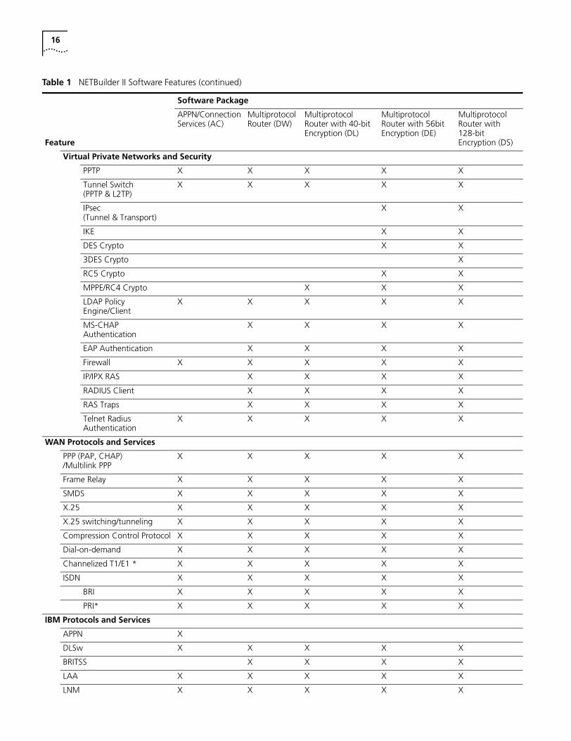
Table 1 NETBuilder II Software Features (continued)
Software Package
Feature
APPN/Connection Services (AC)
Multiprotocol Router (DW)
Multiprotocol Router with 40-bit Encryption (DL)
Multiprotocol Router with 56bit Encryption (DE)
Multiprotocol Router with 128-bit Encryption (DS)
11.3 Software Packages 17
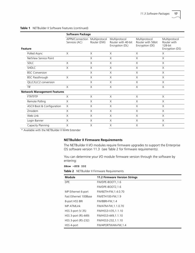
NETBuilder II Firmware Requirements
The NETBuilder II I/O modules require firmware upgrades to support the Enterprise OS software version 11.3 (see Table 2 for firmware requirements).
You can determine your I/O module firmware version through the software by entering:
SHow -SYS IOI
Polled Async X X X X X
NetView Service Point X X X X
SDLC X X X X X
SHDLC X X X X X
BSC Conversion X X X X
BSC Passthrough X X X X X
QLLC/LLC2 conversion X X X X
TIF X X X X X
Network Management Features
FTP/TFTP X X X X X
Remote Polling X X X X X
ASCII Boot & Configuration X X X X X
Zmodem X X X X X
Web Link X X X X X
Login Banner X X X X X
Capacity Planning X X X X X
* Available with the NETBuilder II WAN Extender
Table 1 NETBuilder II Software Features (continued)
Software Package
Feature
APPN/Connection Services (AC)
Multiprotocol Router (DW)
Multiprotocol Router with 40-bit Encryption (DL)
Multiprotocol Router with 56bit Encryption (DE)
Multiprotocol Router with 128-bit Encryption (DS)
Table 2 NETBuilder II Firmware Requirements
Module 11.2 Firmware Version Strings
DPE FW/DPE-BOOT1,1.6
FW/DPE-BOOT2,1.6
MP Ethernet 6-port FW/6ETH-FW,1.4.0.70
Fast Ethernet 100Base FW/ETH100-FW,1.9
8-port HSS BRI FW/8BRI-FW,1.4
MP ATMLink FW/ATM-FW,1.1.0.70
HSS 3-port (V.35) FW/HSS3-V35,1.1.10
HSS 3-port (RS-449) FW/HSS3-449,1.1.10
HSS 3-port (RS-232) FW/HSS3-232,1.1.10
HSS 4-port FW/4PORTWAN-FW,1.4
18
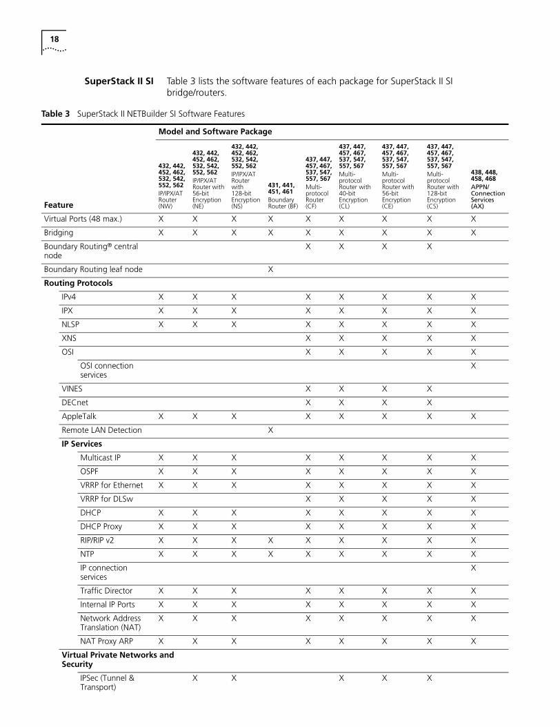
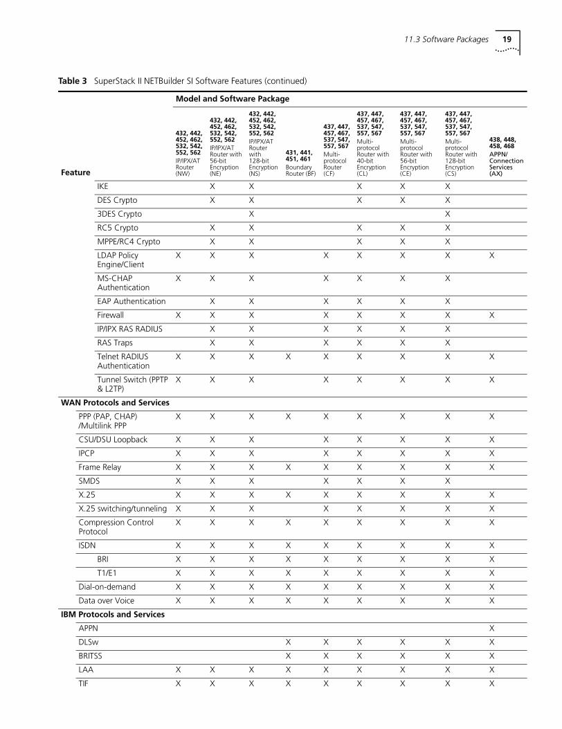
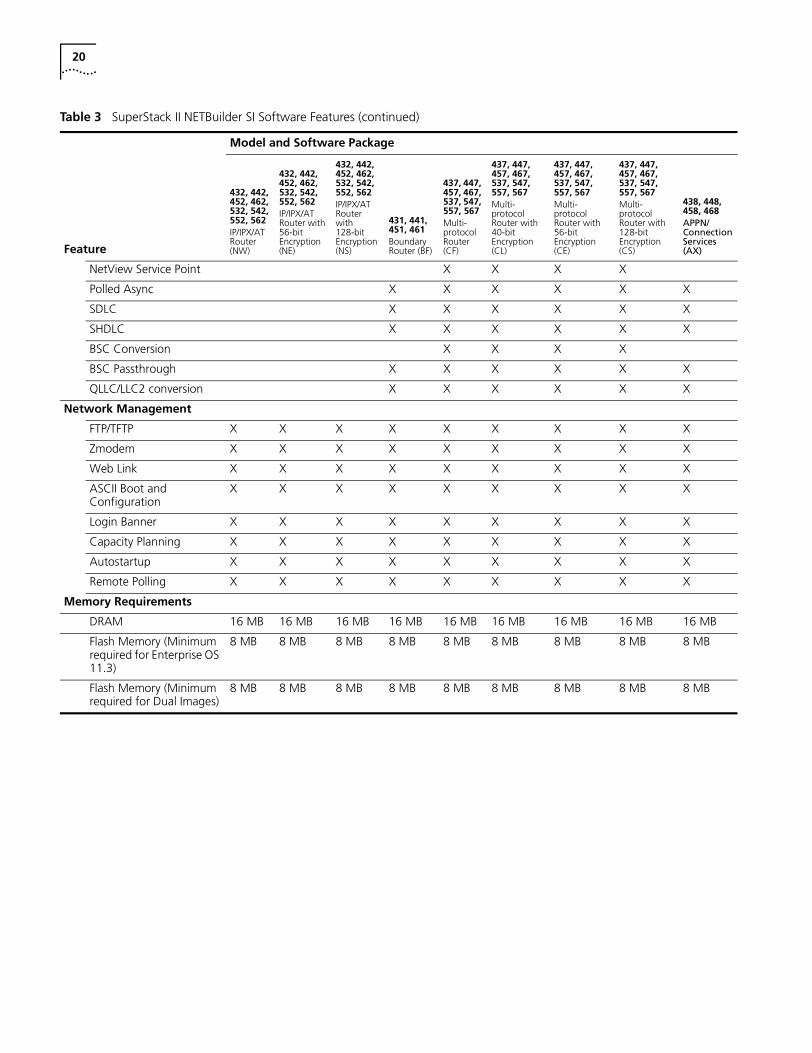
SuperStack II SI Table 3 lists the software features of each package for SuperStack II SI bridge/routers.
Table 3 SuperStack II NETBuilder SI Software Features
Model and Software Package
432, 442, 452, 462, 532, 542, 552, 562IP/IPX/AT Router (NW)
432, 442, 452, 462,532, 542, 552, 562IP/IPX/AT Router with 56-bitEncryption (NE)
432, 442, 452, 462, 532, 542, 552, 562IP/IPX/AT Router with 128-bitEncryption (NS)
431, 441, 451, 461Boundary Router (BF)
437, 447, 457, 467, 537, 547, 557, 567Multi-protocol Router (CF)
437, 447, 457, 467, 537, 547, 557, 567Multi-protocol Router with 40-bitEncryption (CL)
437, 447, 457, 467, 537, 547, 557, 567Multi-protocol Router with 56-bitEncryption (CE)
437, 447, 457, 467, 537, 547, 557, 567Multi-protocol Router with 128-bitEncryption (CS)
438, 448, 458, 468APPN/ Connection Services (AX)Feature
Virtual Ports (48 max.) X X X X X X X X X
Bridging X X X X X X X X X
Boundary Routing® central node
X X X X
Boundary Routing leaf node X
Routing Protocols
IPv4 X X X X X X X X
IPX X X X X X X X X
NLSP X X X X X X X X
XNS X X X X X
OSI X X X X X
OSI connection services
X
VINES X X X X
DECnet X X X X
AppleTalk X X X X X X X X
Remote LAN Detection X
IP Services
Multicast IP X X X X X X X X
OSPF X X X X X X X X
VRRP for Ethernet X X X X X X X X
VRRP for DLSw X X X X X
DHCP X X X X X X X X
DHCP Proxy X X X X X X X X
RIP/RIP v2 X X X X X X X X X
NTP X X X X X X X X X
IP connection services
X
Traffic Director X X X X X X X X
Internal IP Ports X X X X X X X X
Network Address Translation (NAT)
X X X X X X X X
NAT Proxy ARP X X X X X X X X
Virtual Private Networks and Security
IPSec (Tunnel & Transport)
X X X X X
11.3 Software Packages 19
IKE X X X X X
DES Crypto X X X X X
3DES Crypto X X
RC5 Crypto X X X X X
MPPE/RC4 Crypto X X X X X
LDAP Policy Engine/Client
X X X X X X X X
MS-CHAP Authentication
X X X X X X X
EAP Authentication X X X X X X
Firewall X X X X X X X X
IP/IPX RAS RADIUS X X X X X X
RAS Traps X X X X X X
Telnet RADIUS Authentication
X X X X X X X X X
Tunnel Switch (PPTP & L2TP)
X X X X X X X X
WAN Protocols and Services
PPP (PAP, CHAP) /Multilink PPP
X X X X X X X X X
CSU/DSU Loopback X X X X X X X X
IPCP X X X X X X X X
Frame Relay X X X X X X X X X
SMDS X X X X X X X
X.25 X X X X X X X X X
X.25 switching/tunneling X X X X X X X X
Compression Control Protocol
X X X X X X X X X
ISDN X X X X X X X X X
BRI X X X X X X X X X
T1/E1 X X X X X X X X X
Dial-on-demand X X X X X X X X X
Data over Voice X X X X X X X X X
IBM Protocols and Services
APPN X
DLSw X X X X X X
BRITSS X X X X X X
LAA X X X X X X X X X
TIF X X X X X X X X X
Table 3 SuperStack II NETBuilder SI Software Features (continued)
Model and Software Package
432, 442, 452, 462, 532, 542, 552, 562IP/IPX/AT Router (NW)
432, 442, 452, 462,532, 542, 552, 562IP/IPX/AT Router with 56-bitEncryption (NE)
432, 442, 452, 462, 532, 542, 552, 562IP/IPX/AT Router with 128-bitEncryption (NS)
431, 441, 451, 461Boundary Router (BF)
437, 447, 457, 467, 537, 547, 557, 567Multi-protocol Router (CF)
437, 447, 457, 467, 537, 547, 557, 567Multi-protocol Router with 40-bitEncryption (CL)
437, 447, 457, 467, 537, 547, 557, 567Multi-protocol Router with 56-bitEncryption (CE)
437, 447, 457, 467, 537, 547, 557, 567Multi-protocol Router with 128-bitEncryption (CS)
438, 448, 458, 468APPN/ Connection Services (AX)Feature
20
NetView Service Point X X X X
Polled Async X X X X X X
SDLC X X X X X X
SHDLC X X X X X X
BSC Conversion X X X X
BSC Passthrough X X X X X X
QLLC/LLC2 conversion X X X X X X
Network Management
FTP/TFTP X X X X X X X X X
Zmodem X X X X X X X X X
Web Link X X X X X X X X X
ASCII Boot and Configuration
X X X X X X X X X
Login Banner X X X X X X X X X
Capacity Planning X X X X X X X X X
Autostartup X X X X X X X X X
Remote Polling X X X X X X X X X
Memory Requirements
DRAM 16 MB 16 MB 16 MB 16 MB 16 MB 16 MB 16 MB 16 MB 16 MB
Flash Memory (Minimum required for Enterprise OS 11.3)
8 MB 8 MB 8 MB 8 MB 8 MB 8 MB 8 MB 8 MB 8 MB
Flash Memory (Minimum required for Dual Images)
8 MB 8 MB 8 MB 8 MB 8 MB 8 MB 8 MB 8 MB 8 MB
Table 3 SuperStack II NETBuilder SI Software Features (continued)
Model and Software Package
432, 442, 452, 462, 532, 542, 552, 562IP/IPX/AT Router (NW)
432, 442, 452, 462,532, 542, 552, 562IP/IPX/AT Router with 56-bitEncryption (NE)
432, 442, 452, 462, 532, 542, 552, 562IP/IPX/AT Router with 128-bitEncryption (NS)
431, 441, 451, 461Boundary Router (BF)
437, 447, 457, 467, 537, 547, 557, 567Multi-protocol Router (CF)
437, 447, 457, 467, 537, 547, 557, 567Multi-protocol Router with 40-bitEncryption (CL)
437, 447, 457, 467, 537, 547, 557, 567Multi-protocol Router with 56-bitEncryption (CE)
437, 447, 457, 467, 537, 547, 557, 567Multi-protocol Router with 128-bitEncryption (CS)
438, 448, 458, 468APPN/ Connection Services (AX)Feature
11.3 Software Packages 21
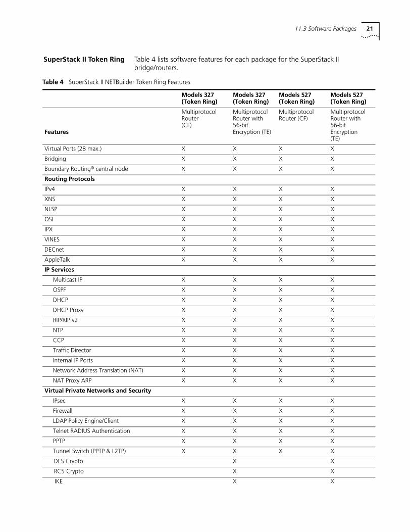
SuperStack II Token Ring Table 4 lists software features for each package for the SuperStack II bridge/routers.
Table 4 SuperStack II NETBuilder Token Ring Features
Models 327 (Token Ring)
Models 327 (Token Ring)
Models 527 (Token Ring)
Models 527 (Token Ring)
Features
Multiprotocol Router (CF)
Multiprotocol Router with 56-bit Encryption (TE)
Multiprotocol Router (CF)
Multiprotocol Router with 56-bit Encryption(TE)
Virtual Ports (28 max.) X X X X
Bridging X X X X
Boundary Routing® central node X X X X
Routing Protocols
IPv4 X X X X
XNS X X X X
NLSP X X X X
OSI X X X X
IPX X X X X
VINES X X X X
DECnet X X X X
AppleTalk X X X X
IP Services
Multicast IP X X X X
OSPF X X X X
DHCP X X X X
DHCP Proxy X X X X
RIP/RIP v2 X X X X
NTP X X X X
CCP X X X X
Traffic Director X X X X
Internal IP Ports X X X X
Network Address Translation (NAT) X X X X
NAT Proxy ARP X X X X
Virtual Private Networks and Security
IPsec X X X X
Firewall X X X X
LDAP Policy Engine/Client X X X X
Telnet RADIUS Authentication X X X X
PPTP X X X X
Tunnel Switch (PPTP & L2TP) X X X X
DES Crypto X X
RC5 Crypto X X
IKE X X
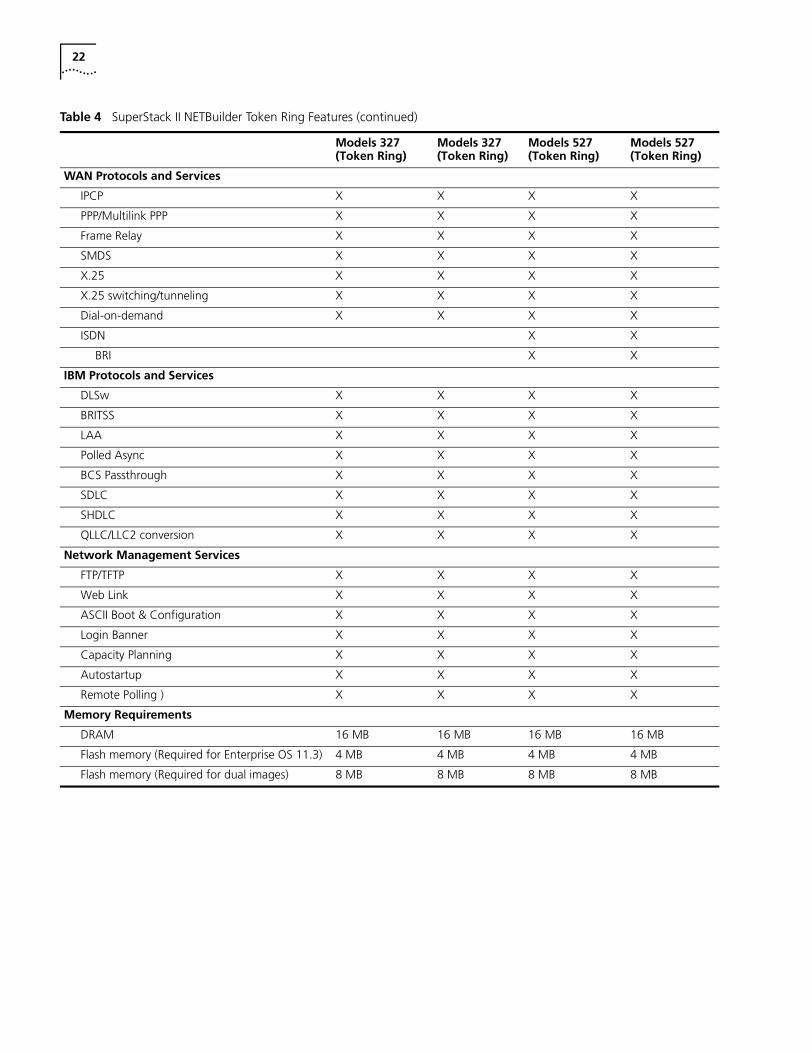
22
WAN Protocols and Services
IPCP X X X X
PPP/Multilink PPP X X X X
Frame Relay X X X X
SMDS X X X X
X.25 X X X X
X.25 switching/tunneling X X X X
Dial-on-demand X X X X
ISDN X X
BRI X X
IBM Protocols and Services
DLSw X X X X
BRITSS X X X X
LAA X X X X
Polled Async X X X X
BCS Passthrough X X X X
SDLC X X X X
SHDLC X X X X
QLLC/LLC2 conversion X X X X
Network Management Services
FTP/TFTP X X X X
Web Link X X X X
ASCII Boot & Configuration X X X X
Login Banner X X X X
Capacity Planning X X X X
Autostartup X X X X
Remote Polling ) X X X X
Memory Requirements
DRAM 16 MB 16 MB 16 MB 16 MB
Flash memory (Required for Enterprise OS 11.3) 4 MB 4 MB 4 MB 4 MB
Flash memory (Required for dual images) 8 MB 8 MB 8 MB 8 MB
Table 4 SuperStack II NETBuilder Token Ring Features (continued)
Models 327 (Token Ring)
Models 327 (Token Ring)
Models 527 (Token Ring)
Models 527 (Token Ring)
11.3 Software Packages 23
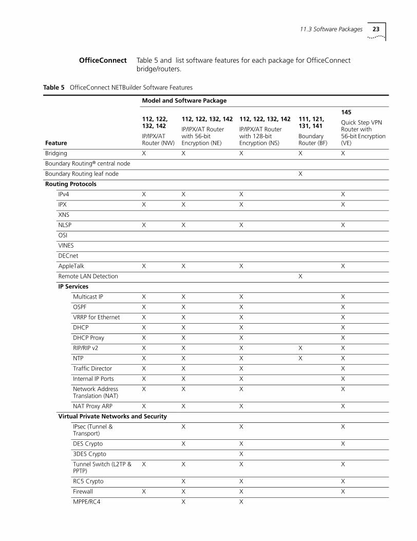
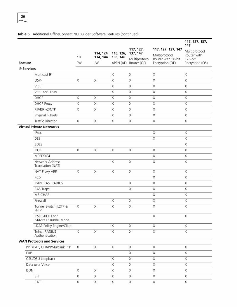
OfficeConnect Table 5 and list software features for each package for OfficeConnect bridge/routers.
Table 5 OfficeConnect NETBuilder Software Features
Model and Software Package
112, 122, 132, 142
IP/IPX/AT Router (NW)
112, 122, 132, 142
IP/IPX/AT Router with 56-bit Encryption (NE)
112, 122, 132, 142
IP/IPX/AT Router with 128-bit Encryption (NS)
111, 121, 131, 141
Boundary Router (BF)
145
Quick Step VPN Router with 56-bit Encryption (VE)Feature
Bridging X X X X X
Boundary Routing® central node
Boundary Routing leaf node X
Routing Protocols
IPv4 X X X X
IPX X X X X
XNS
NLSP X X X X
OSI
VINES
DECnet
AppleTalk X X X X
Remote LAN Detection X
IP Services
Multicast IP X X X X
OSPF X X X X
VRRP for Ethernet X X X X
DHCP X X X X
DHCP Proxy X X X X
RIP/RIP v2 X X X X X
NTP X X X X X
Traffic Director X X X X
Internal IP Ports X X X X
Network Address Translation (NAT)
X X X X
NAT Proxy ARP X X X X
Virtual Private Networks and Security
IPsec (Tunnel & Transport)
X X X
DES Crypto X X X
3DES Crypto X
Tunnel Switch (L2TP & PPTP)
X X X X
RC5 Crypto X X X
Firewall X X X X
MPPE/RC4 X X
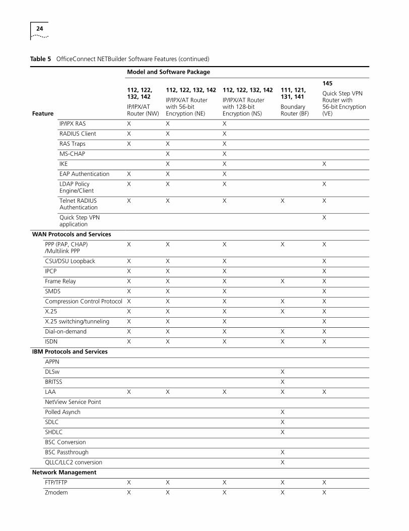
24
IP/IPX RAS X X X
RADIUS Client X X X
RAS Traps X X X
MS-CHAP X X
IKE X X X
EAP Authentication X X X
LDAP Policy Engine/Client
X X X X
Telnet RADIUS Authentication
X X X X X
Quick Step VPN application
X
WAN Protocols and Services
PPP (PAP, CHAP) /Multilink PPP
X X X X X
CSU/DSU Loopback X X X X
IPCP X X X X
Frame Relay X X X X X
SMDS X X X X
Compression Control Protocol X X X X X
X.25 X X X X X
X.25 switching/tunneling X X X X
Dial-on-demand X X X X X
ISDN X X X X X
IBM Protocols and Services
APPN
DLSw X
BRITSS X
LAA X X X X X
NetView Service Point
Polled Asynch X
SDLC X
SHDLC X
BSC Conversion
BSC Passthrough X
QLLC/LLC2 conversion X
Network Management
FTP/TFTP X X X X X
Zmodem X X X X X
Table 5 OfficeConnect NETBuilder Software Features (continued)
Model and Software Package
112, 122, 132, 142
IP/IPX/AT Router (NW)
112, 122, 132, 142
IP/IPX/AT Router with 56-bit Encryption (NE)
112, 122, 132, 142
IP/IPX/AT Router with 128-bit Encryption (NS)
111, 121, 131, 141
Boundary Router (BF)
145
Quick Step VPN Router with 56-bit Encryption (VE)Feature
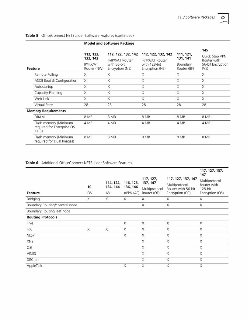
11.3 Software Packages 25
Remote Polling X X X X X
ASCII Boot & Configuration X X X X X
Autostartup X X X X X
Capacity Planning X X X X X
Web Link X X X X X
Virtual Ports 28 28 28 28 28
Memory Requirements
DRAM 8 MB 8 MB 8 MB 8 MB 8 MB
Flash memory (Minimum required for Enterprise OS 11.3)
4 MB 4 MB 4 MB 4 MB 4 MB
Flash memory (Minimum required for Dual Images)
8 MB 8 MB 8 MB 8 MB 8 MB
Table 5 OfficeConnect NETBuilder Software Features (continued)
Model and Software Package
112, 122, 132, 142
IP/IPX/AT Router (NW)
112, 122, 132, 142
IP/IPX/AT Router with 56-bit Encryption (NE)
112, 122, 132, 142
IP/IPX/AT Router with 128-bit Encryption (NS)
111, 121, 131, 141
Boundary Router (BF)
145
Quick Step VPN Router with 56-bit Encryption (VE)Feature
Table 6 Additional OfficeConnect NETBuilder Software Features
116, 126, 136, 146
APPN (AF)
117, 127, 137, 147
Multiprotocol Router (OF)
117, 127, 137, 147
Multiprotocol Router with 56-bit Encryption (OE)
117, 127, 137, 147
Multiprotocol Router with 128-bit Encryption (OS)Feature
10
FW
114, 124, 134, 144
JW
Bridging X X X X X X
Boundary Routing® central node X X X
Boundary Routing leaf node
Routing Protocols
IPv4 X X X X
IPX X X X X X X
NLSP X X X X
XNS X X X
OSI X X X
VINES X X X
DECnet X X X
AppleTalk X X X X
26
IP Services
Multicast IP X X X X
OSPF X X X X X X
VRRP X X X X
VRRP for DLSw X X X X
DHCP X X X X X X
DHCP Proxy X X X X X X
RIP/RIP v2/NTP X X X X X X
Internal IP Ports X X X X
Traffic Director X X X X X X
Virtual Private Networks
IPsec X X
DES X X
3DES X
IPCP X X X X X X
MPPE/RC4 X X
Network Address Translation (NAT)
X X X X
NAT Proxy ARP X X X X X X
RC5 X X
IP/IPX RAS, RADIUS X X X
RAS Traps X X X
MS-CHAP X X
Firewall X X X X
Tunnel Switch (L2TP & PPTP)
X X X X X X
IPSEC-KEK Enh/ISKMP/ IP Tunnel Mode
X X
LDAP Policy Engine/Client X X X X
Telnet RADIUS Authentication
X X X X X X
WAN Protocols and Services
PPP (PAP, CHAP)/Multilink PPP X X X X X X
EAP X X X
CSU/DSU Loopback X X X X
Data over Voice X X X X
ISDN X X X X X X
BRI X X X X X X
E1/T1 X X X X X X
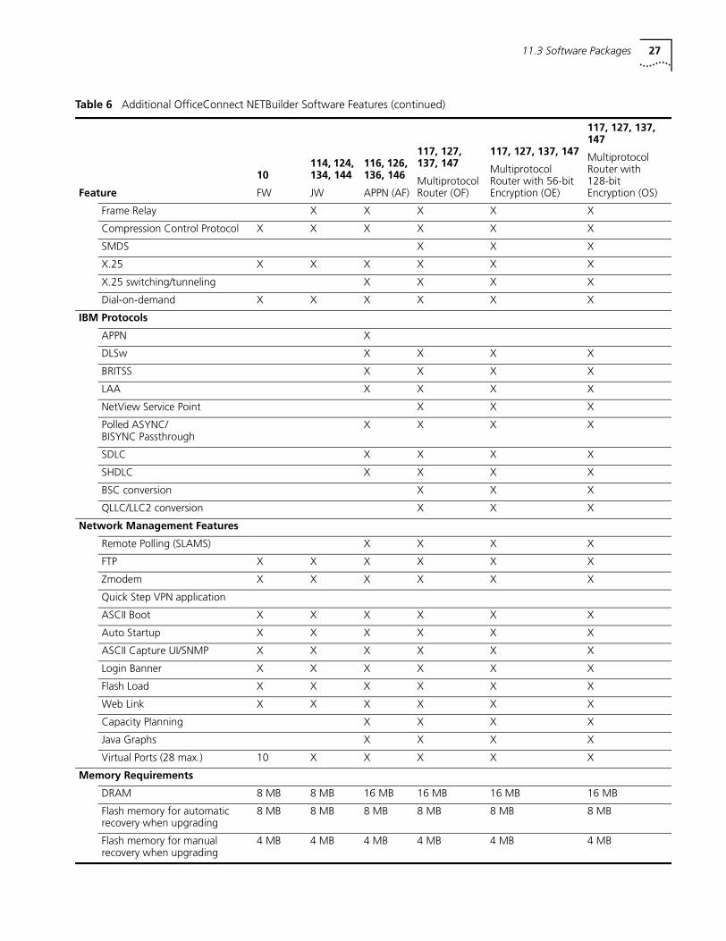
Table 6 Additional OfficeConnect NETBuilder Software Features (continued)
116, 126, 136, 146
APPN (AF)
117, 127, 137, 147
Multiprotocol Router (OF)
117, 127, 137, 147
Multiprotocol Router with 56-bit Encryption (OE)
117, 127, 137, 147
Multiprotocol Router with 128-bit Encryption (OS)Feature
10
FW
114, 124, 134, 144
JW
11.3 Software Packages 27
Frame Relay X X X X X
Compression Control Protocol X X X X X X
SMDS X X X
X.25 X X X X X X
X.25 switching/tunneling X X X X
Dial-on-demand X X X X X X
IBM Protocols
APPN X
DLSw X X X X
BRITSS X X X X
LAA X X X X
NetView Service Point X X X
Polled ASYNC/BISYNC Passthrough
X X X X
SDLC X X X X
SHDLC X X X X
BSC conversion X X X
QLLC/LLC2 conversion X X X
Network Management Features
Remote Polling (SLAMS) X X X X
FTP X X X X X X
Zmodem X X X X X X
Quick Step VPN application
ASCII Boot X X X X X X
Auto Startup X X X X X X
ASCII Capture UI/SNMP X X X X X X
Login Banner X X X X X X
Flash Load X X X X X X
Web Link X X X X X X
Capacity Planning X X X X
Java Graphs X X X X
Virtual Ports (28 max.) 10 X X X X X
Memory Requirements
DRAM 8 MB 8 MB 16 MB 16 MB 16 MB 16 MB
Flash memory for automatic recovery when upgrading
8 MB 8 MB 8 MB 8 MB 8 MB 8 MB
Flash memory for manual recovery when upgrading
4 MB 4 MB 4 MB 4 MB 4 MB 4 MB
Table 6 Additional OfficeConnect NETBuilder Software Features (continued)
116, 126, 136, 146
APPN (AF)
117, 127, 137, 147
Multiprotocol Router (OF)
117, 127, 137, 147
Multiprotocol Router with 56-bit Encryption (OE)
117, 127, 137, 147
Multiprotocol Router with 128-bit Encryption (OS)Feature
10
FW
114, 124, 134, 144
JW
28
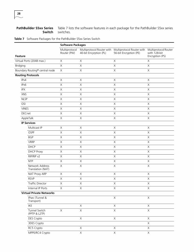
PathBuilder S5xx SeriesSwitch
Table 7 lists the software features in each package for the PathBuilder S5xx series switches.
Table 7 Software Packages for the PathBuilder S5xx Series Switch
Software Packages
Feature
Multiprotocol Router (PW)
Multiprotocol Router with 40-bit Encyrption (PL)
Multiprotocol Router with 56-bit Encryption (PE)
Multiprotocol Router with 128-bit Encryption (PS)
Virtual Ports (2048 max.) X X X X
Bridging X X X X
Boundary Routing® central node X X X X
Routing Protocols
IPv4 X X X X
IPv6 X X X X
IPX X X X X
XNS X X X X
NLSP X X X X
OSI X X X X
VINES X X X X
DECnet X X X X
AppleTalk X X X X
IP Services
Multicast IP X X X X
OSPF X X X X
BGP X X X X
VRRP X X X X
DHCP X X X X
DHCP Proxy X X X X
RIP/RIP v2 X X X X
NTP X X X X
Network Address Translation (NAT)
X X X X
NAT Proxy ARP X X X X
RSVP X X X X
Traffic Director X X X X
Internal IP Ports X X X X
Virtual Private Networks
IPsec (Tunnel & Transport)
X X
IKE X X X
Tunnel Switch (PPTP & L2TP)
X X X X
DES Crypto X X X
3DES Crypto X
RC5 Crypto X X X
MPPE/RC4 Crypto X X X
11.3 Software Packages 29
MS-CHAP Authentication
X X X X
EAP Authentication X X X X
Firewall X X X X
IP/IPX RAS X X X X
RADIUS Client X X X
RAS Traps X
LDAP Policy Engine/Client
X X X X
Telnet RADIUS Authentication
X X X X
RAS Traps X X
WAN Protocols and Services
PPP (PAP, CHAP)/Multilink PPP X X X X
Frame Relay X X X X
Dial-on-demand X X X X
SMDS X X X X
X.25 X X X X
X.25 switching/tunneling X X X X
ISDN X X X X
PRI X X X X
Compression Control Protocol X X X X
IBM Protocols and Services
DLSw X X X X
VRRP for DLSw X X X X
BRITSS X X X X
LAA X X X X
LNM X X X X
Polled Async X X X X
TIF X X X X
NetView Service Point X X X X
SDLC X X X X
SHDLC X X X X
BSC Conversion X X X X
BSC Passthrough X X X X
QLLC/LLC2 conversion X X X X
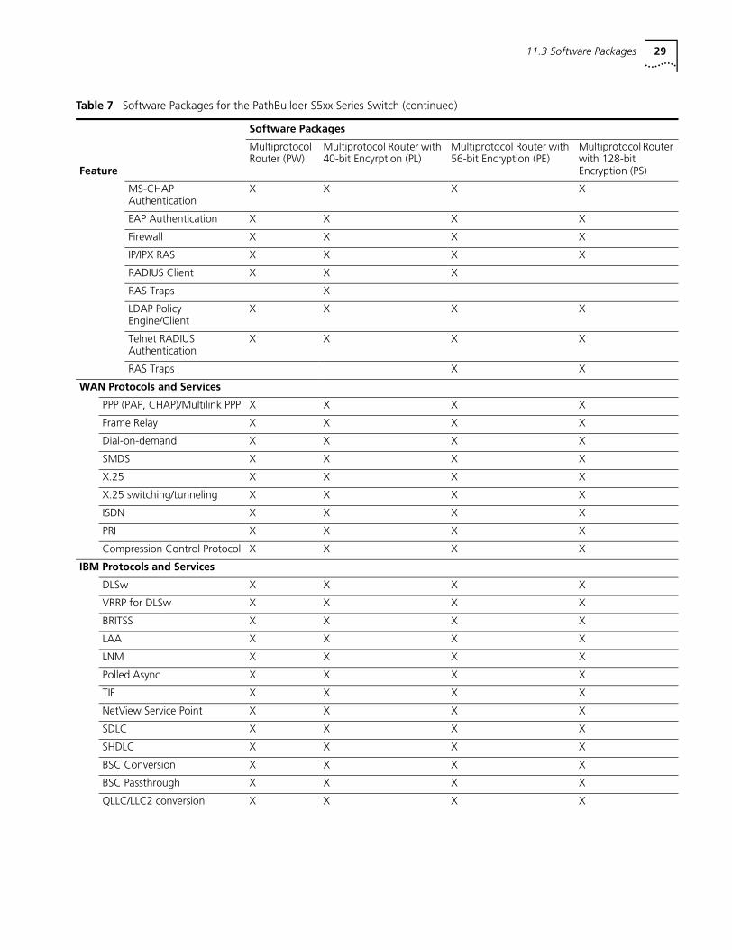
Table 7 Software Packages for the PathBuilder S5xx Series Switch (continued)
Software Packages
Feature
Multiprotocol Router (PW)
Multiprotocol Router with 40-bit Encyrption (PL)
Multiprotocol Router with 56-bit Encryption (PE)
Multiprotocol Router with 128-bit Encryption (PS)
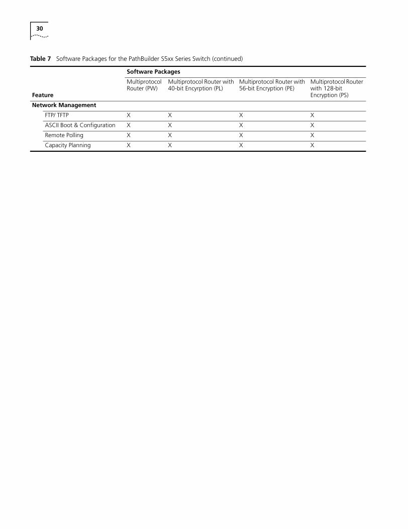
30
Network Management
FTP/ TFTP X X X X
ASCII Boot & Configuration X X X X
Remote Polling X X X X
Capacity Planning X X X X
Table 7 Software Packages for the PathBuilder S5xx Series Switch (continued)
Software Packages
Feature
Multiprotocol Router (PW)
Multiprotocol Router with 40-bit Encyrption (PL)
Multiprotocol Router with 56-bit Encryption (PE)
Multiprotocol Router with 128-bit Encryption (PS)
Upgrade Management Utilities 31
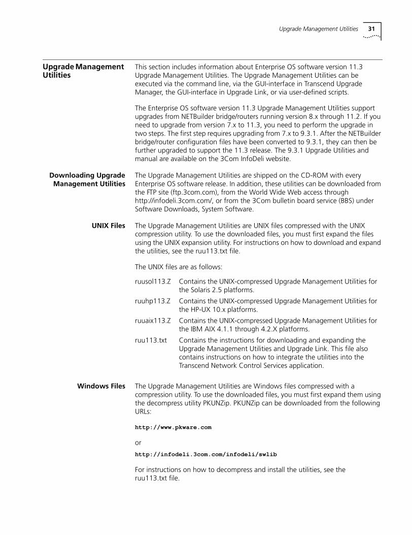
Upgrade Management Utilities
This section includes information about Enterprise OS software version 11.3 Upgrade Management Utilities. The Upgrade Management Utilities can be executed via the command line, via the GUI-interface in Transcend Upgrade Manager, the GUI-interface in Upgrade Link, or via user-defined scripts.
The Enterprise OS software version 11.3 Upgrade Management Utilities support upgrades from NETBuilder bridge/routers running version 8.x through 11.2. If you need to upgrade from version 7.x to 11.3, you need to perform the upgrade in two steps. The first step requires upgrading from 7.x to 9.3.1. After the NETBuilder bridge/router configuration files have been converted to 9.3.1, they can then be further upgraded to support the 11.3 release. The 9.3.1 Upgrade Utilities and manual are available on the 3Com InfoDeli website.
Downloading UpgradeManagement Utilities
The Upgrade Management Utilities are shipped on the CD-ROM with every Enterprise OS software release. In addition, these utilities can be downloaded from the FTP site (ftp.3com.com), from the World Wide Web access through http://infodeli.3com.com/, or from the 3Com bulletin board service (BBS) under Software Downloads, System Software.
UNIX Files The Upgrade Management Utilities are UNIX files compressed with the UNIX compression utility. To use the downloaded files, you must first expand the files using the UNIX expansion utility. For instructions on how to download and expand the utilities, see the ruu113.txt file.
The UNIX files are as follows:
Windows Files The Upgrade Management Utilities are Windows files compressed with a compression utility. To use the downloaded files, you must first expand them using the decompress utility PKUNZip. PKUNZip can be downloaded from the following URLs:
http://www.pkware.com
or
http://infodeli.3com.com/infodeli/swlib
For instructions on how to decompress and install the utilities, see the ruu113.txt file.
ruusol113.Z Contains the UNIX-compressed Upgrade Management Utilities for the Solaris 2.5 platforms.
ruuhp113.Z Contains the UNIX-compressed Upgrade Management Utilities for the HP-UX 10.x platforms.
ruuaix113.Z Contains the UNIX-compressed Upgrade Management Utilities for the IBM AIX 4.1.1 through 4.2.X platforms.
ruu113.txt Contains the instructions for downloading and expanding the Upgrade Management Utilities and Upgrade Link. This file also contains instructions on how to integrate the utilities into the Transcend Network Control Services application.
32
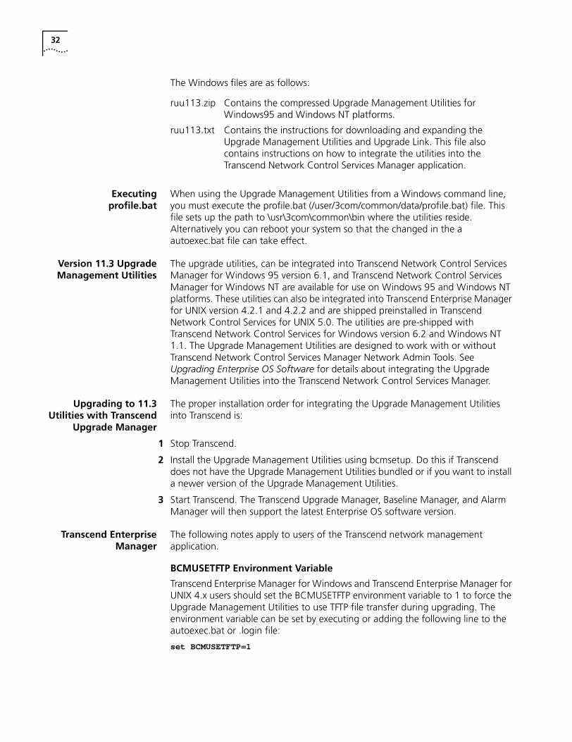
The Windows files are as follows:
Executingprofile.bat
When using the Upgrade Management Utilities from a Windows command line, you must execute the profile.bat (/user/3com/common/data/profile.bat) file. This file sets up the path to \usr\3com\common\bin where the utilities reside. Alternatively you can reboot your system so that the changed in the a autoexec.bat file can take effect.
Version 11.3 UpgradeManagement Utilities
The upgrade utilities, can be integrated into Transcend Network Control Services Manager for Windows 95 version 6.1, and Transcend Network Control Services Manager for Windows NT are available for use on Windows 95 and Windows NT platforms. These utilities can also be integrated into Transcend Enterprise Manager for UNIX version 4.2.1 and 4.2.2 and are shipped preinstalled in Transcend Network Control Services for UNIX 5.0. The utilities are pre-shipped with Transcend Network Control Services for Windows version 6.2 and Windows NT 1.1. The Upgrade Management Utilities are designed to work with or without Transcend Network Control Services Manager Network Admin Tools. See Upgrading Enterprise OS Software for details about integrating the Upgrade Management Utilities into the Transcend Network Control Services Manager.
Upgrading to 11.3Utilities with Transcend
Upgrade Manager
The proper installation order for integrating the Upgrade Management Utilities into Transcend is:
1 Stop Transcend.
2 Install the Upgrade Management Utilities using bcmsetup. Do this if Transcend does not have the Upgrade Management Utilities bundled or if you want to install a newer version of the Upgrade Management Utilities.
3 Start Transcend. The Transcend Upgrade Manager, Baseline Manager, and Alarm Manager will then support the latest Enterprise OS software version.
Transcend EnterpriseManager
The following notes apply to users of the Transcend network management application.
BCMUSETFTP Environment Variable
Transcend Enterprise Manager for Windows and Transcend Enterprise Manager for UNIX 4.x users should set the BCMUSETFTP environment variable to 1 to force the Upgrade Management Utilities to use TFTP file transfer during upgrading. The environment variable can be set by executing or adding the following line to the autoexec.bat or .login file:
set BCMUSETFTP=1
ruu113.zip Contains the compressed Upgrade Management Utilities for Windows95 and Windows NT platforms.
ruu113.txt Contains the instructions for downloading and expanding the Upgrade Management Utilities and Upgrade Link. This file also contains instructions on how to integrate the utilities into the Transcend Network Control Services Manager application.
Upgrade Management Notes 33
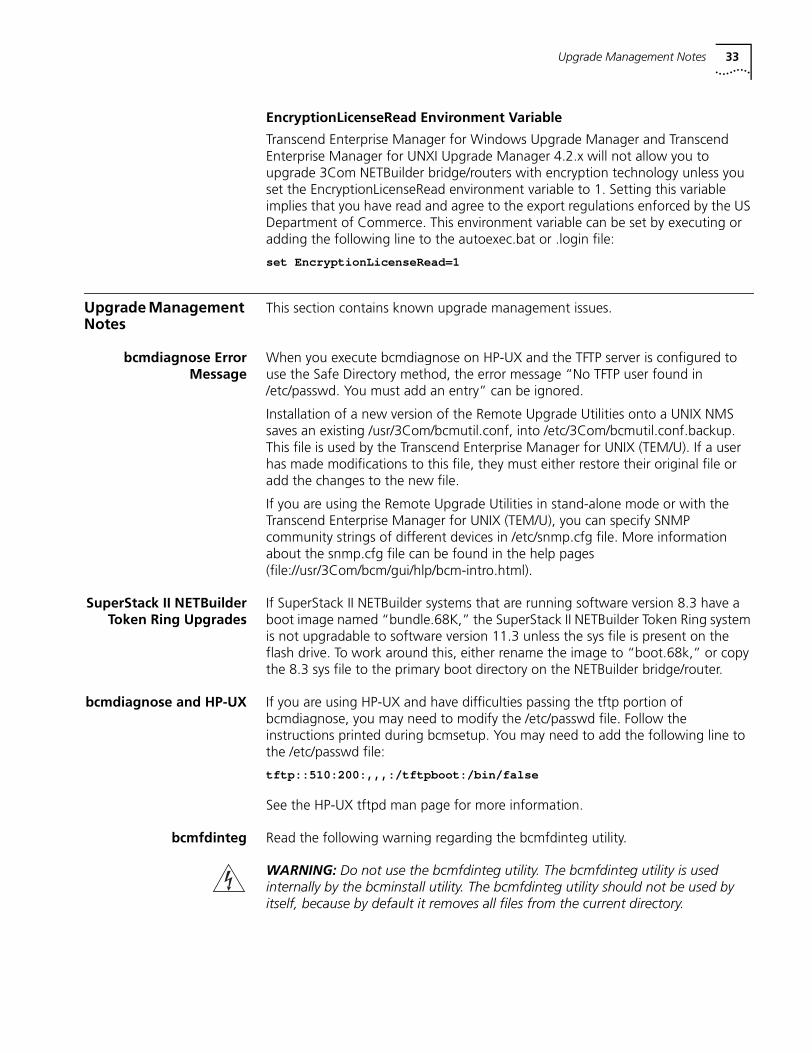
EncryptionLicenseRead Environment Variable
Transcend Enterprise Manager for Windows Upgrade Manager and Transcend Enterprise Manager for UNXI Upgrade Manager 4.2.x will not allow you to upgrade 3Com NETBuilder bridge/routers with encryption technology unless you set the EncryptionLicenseRead environment variable to 1. Setting this variable implies that you have read and agree to the export regulations enforced by the US Department of Commerce. This environment variable can be set by executing or adding the following line to the autoexec.bat or .login file:
set EncryptionLicenseRead=1
Upgrade Management Notes
This section contains known upgrade management issues.
bcmdiagnose ErrorMessage
When you execute bcmdiagnose on HP-UX and the TFTP server is configured to use the Safe Directory method, the error message “No TFTP user found in /etc/passwd. You must add an entry” can be ignored.
Installation of a new version of the Remote Upgrade Utilities onto a UNIX NMS saves an existing /usr/3Com/bcmutil.conf, into /etc/3Com/bcmutil.conf.backup. This file is used by the Transcend Enterprise Manager for UNIX (TEM/U). If a user has made modifications to this file, they must either restore their original file or add the changes to the new file.
If you are using the Remote Upgrade Utilities in stand-alone mode or with the Transcend Enterprise Manager for UNIX (TEM/U), you can specify SNMP community strings of different devices in /etc/snmp.cfg file. More information about the snmp.cfg file can be found in the help pages (file://usr/3Com/bcm/gui/hlp/bcm-intro.html).
SuperStack II NETBuilderToken Ring Upgrades
If SuperStack II NETBuilder systems that are running software version 8.3 have a boot image named “bundle.68K,” the SuperStack II NETBuilder Token Ring system is not upgradable to software version 11.3 unless the sys file is present on the flash drive. To work around this, either rename the image to “boot.68k,” or copy the 8.3 sys file to the primary boot directory on the NETBuilder bridge/router.
bcmdiagnose and HP-UX If you are using HP-UX and have difficulties passing the tftp portion of bcmdiagnose, you may need to modify the /etc/passwd file. Follow the instructions printed during bcmsetup. You may need to add the following line to the /etc/passwd file:
tftp::510:200:,,,:/tftpboot:/bin/false
See the HP-UX tftpd man page for more information.
bcmfdinteg Read the following warning regarding the bcmfdinteg utility.
WARNING: Do not use the bcmfdinteg utility. The bcmfdinteg utility is used internally by the bcminstall utility. The bcmfdinteg utility should not be used by itself, because by default it removes all files from the current directory.
34
File ConversionConsiderations
This section describes file conversion considerations for APPN, bridge static routes, DLSw, the PROfile service, and X.25 SVCs.
APPN
APPN file conversion is supported in software version 8.2 and later. Upgrading from software versions prior to 8.2 requires manual configuration.
High Performance Routing (HPR) is a new feature for the NETBuilder bridge/router after software version 8.3. If you use the Upgrade Management Utilities to convert your APPN data file from version 8.3 (or later) to 11.3, be sure to turn on HPR if HPR is desired using:
SETDefault !<port> -APPN PortDef = <DLC type> HPR=yes
Bridge Static Routes
A static bridge route configured with the off option does not convert properly. You must manually reconfigure this route.
DLSw
Initial Bandwidth for Peer is a new parameter for software version 8.3 and later. The default for version 11.0 is 8000. If you use the Upgrade Management Utilities to convert your DLSw data files from version 8.3 (or later) to 11.3, be sure to set the value of the parameter to the desired value using:
SETDefault <tunnel id> -Dlsw PEER = <IP address> <PrioMode> <8000 | othervalue>
Upgrading From Release8.3 or Earlier
If you are upgrading a bridge/router from software version 8.3 or earlier, you must disable user verification by specifying the -NA flag on bcmnbrus or Upgrade Link. For example:
bcmnbrus -NA
or
UpgradeLink -NA
Otherwise, an error dialog box is returned with the message “Could not verify user.”
If you use tftp, the “Verify Upgrade Services” step does not need the user or password to be verified, so those entries as well as the FTP Client User Name and Password, should be ignored.
Upgrade Link andNetscape Browser Scroll
Bars
Netscape version 4.05 with AWT patch 1.1.5 has the Java support required by Enterprise OS software version 11.3 Upgrade Link. Certain problems have been found with this Netscape patch release, such as sometimes the Netscape browser fails to add scroll bars with text fields. If you experience this or other problems, you may want to use a later version of Netscape when it becomes available.
Upgrade Link WindowResizing
Since Enterprise OS software version 11.3 Upgrade Link cannot resize the browser window, you should maximize the browser window so that all of the Upgrade Link dialog boxes are fully visible without scrolling.
IBM Protocols and Services Notes 35
IBM Protocols and Services Notes
This section describes notes, cautions, and other considerations to be aware of when using the Enterprise OS software when with IBM protocols and services. The topics are presented in alphabetical order.
APPN In software version 11.3, APPN does not support SMDS.
APPN Connections to3174 through
Token Ring
When you connect to a 3174 on a token ring, you may need to enable transparent bridging on the bridge/router. The 3174 may send exchange identification (XID) as a non-source routed frame.
APPN CP-CP Sessionsand SNA Boundary
Routing
If you set up APPN routing in an SNA Boundary Routing configuration from a NETBuilder II bridge/router to a leaf node bridge/router, CP-CP sessions between the remote site PC and the NETBuilder II bridge/router are established before you can configure the Boundary Routing configuration on the NETBuilder II bridge/router. However, after you set the -BCN CONTrol parameter for IBM traffic and enable the -BCN Service, the NETBuilder II bridge/router no longer receives the CP-CP sessions. To work around this problem, first turn off BOOTP on the NETBuilder II port at the central site. An alternative work around is to configure APPN with DLSw at the central site and to use the CEC’s MAC address at the remote site.
APPN CP-CP Sessions onParallel TGs
When parallel transmission groups (TGs) are configured between 3Com network nodes and both TGs support CP-CP sessions, a CP-CP session on one TG does not switch to the other TG if the user disables the port or path. This happens because both sides learn about the link failure at different times. The network node with the disabled port or path learns about the link failure right away and tries to bring CP-CP sessions up on the second TG. However, the second network node does not learn about the link failure until LLC2 times out; because it thinks the link is still up, the second network node does not allow CP-CP sessions to start on the second TG. After five attempts at bringing up CP-CP sessions on the second TG, the second TG will be flagged as not supporting CP-CP sessions, preventing CP-CP sessions from coming up on that second TG. To prevent this situation, manually stop the first TG by entering the SET -APPN LinkStaCONTrol <LinkName> Deactivate command before disabling the port/path. By doing this, both network nodes will learn that the link has gone down at the same time, and CP-CP session can be activated on the second TG.
APPN DLUr Connectionsto 3174 Systems
When you configure an APPN dependent LU requestor (DLUr) connection from a NETBuilder II bridge/router to a 3174 cluster controller, the NETBuilder II network node and the 3174 must be on the same ring. In this configuration, the NETBuilder II token ring port must be set to transparent bridging only.
BSC and Leased Lines The BSC pass-through feature is limited to leased lines and cannot use dialup links.
Boundary Routing andNetView Service Point
When configuring NetView Service Point in a Boundary Routing environment, note that the SSCP-PU session actually flows over LLC2 rather than DLSw, even though the -SNA PortDef parameter is defined as DLSw. As a result, the session does not show up as a DLSw circuit.
36
Configuring BSCand NCPs
When connecting a NETBuilder bridge/router to an Network Control Program (NCP) for a BSC configuration, be careful when disabling the 3780/2780 EP lines. If you try to pull the cable out, the NCP may go into a state that will require the NCP to be rebooted. Check with your IBM service representative for additional details.
DLSw Circuit Balancing Circuit balancing does not work properly if WAN links are set to different speeds. For circuit balancing to work properly, you must have WAN links of the same speed. If the WAN links are different speeds, for example, T1 and 64 K, the bridge/router with circuit balancing learns the route from the T1 link before learning the route from the 64 K link. All circuits are directed to the DLSw tunnel on the T1 link instead of being distributed on both 64 K and T1 DLSw tunnels. Only after alternate routes are in the circuit-balancing router cache will subsequent session establishment be balanced.
DLSw andCONNectUsage
ParameterDefault Change
The default value of the -SYS CONNectUsage parameter is High for NETBuilder bridge/routers with a DPE module. The default value of CONNectUsage for all other platforms is Low. This difference simplifies DLSw configurations.
When the DPE module is used in a non-DLSw configuration, a small amount of memory is allocated (226 K of approximately 12 MB). Non-DLSw configurations in very large networks running OSPF and BGP may require that the CONNectUsage parameter be changed to Low to recapture this 226 K of memory. For all other configurations, this additional small memory allocation should have no effect.
DLSw Prioritization The FLush -SYS STATistics command does not flush DLSw priority statistics. You must use the FLush -DLSw PRioritySTATistics command.
DLSw and IBM BoundaryRouting in Large
Networks
The following considerations are related to DLSw in large networks.
Leaf Node Sessions Support
When a leaf node has more than 50 end stations, use the following tuningparameters:
SETDefault !<port> -LLC2 TransmitWindow = 1SETDefault !<port> -LLC2 RetryCount = 20SETDefault !<port> -LLC2 TImerReply = 10000
Use these parameters for the leaf node and central node WAN ports.
Number of DLSw Circuits
The -SYS CONNectionUsage parameter controls the maximum number of DLSw circuits. The default value of the CONNectionUsage parameter is High for NETBuilder bridge/router with a DPE module and for the boundary router peripheral node, but the default value is low for all other NETBuilder bridge/router platforms. Change this value using:
SETDefault -SYS CONNectionUsage = Low | Medium | High
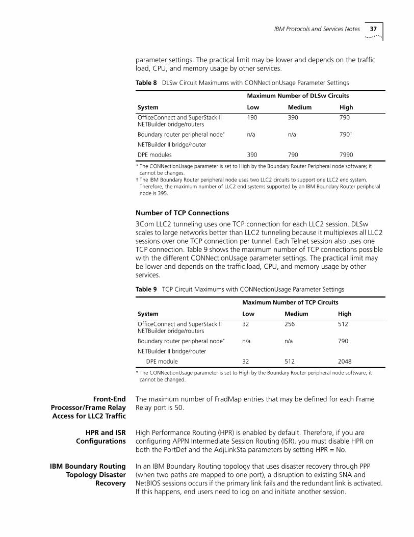
You must reboot the bridge/router before this change takes effect. Table 8 shows the maximum number of circuits possible with the different CONNectionUsage
IBM Protocols and Services Notes 37
parameter settings. The practical limit may be lower and depends on the traffic load, CPU, and memory usage by other services.
Number of TCP Connections
3Com LLC2 tunneling uses one TCP connection for each LLC2 session. DLSw scales to large networks better than LLC2 tunneling because it multiplexes all LLC2 sessions over one TCP connection per tunnel. Each Telnet session also uses one TCP connection. Table 9 shows the maximum number of TCP connections possible with the different CONNectionUsage parameter settings. The practical limit may be lower and depends on the traffic load, CPU, and memory usage by other services.
Front-EndProcessor/Frame RelayAccess for LLC2 Traffic
The maximum number of FradMap entries that may be defined for each Frame Relay port is 50.
HPR and ISRConfigurations
High Performance Routing (HPR) is enabled by default. Therefore, if you are configuring APPN Intermediate Session Routing (ISR), you must disable HPR on both the PortDef and the AdjLinkSta parameters by setting HPR = No.
IBM Boundary RoutingTopology Disaster
Recovery
In an IBM Boundary Routing topology that uses disaster recovery through PPP (when two paths are mapped to one port), a disruption to existing SNA and NetBIOS sessions occurs if the primary link fails and the redundant link is activated. If this happens, end users need to log on and initiate another session.
Table 8 DLSw Circuit Maximums with CONNectionUsage Parameter Settings
Maximum Number of DLSw Circuits
System Low Medium High
OfficeConnect and SuperStack II NETBuilder bridge/routers
190 390 790
Boundary router peripheral node*
* The CONNectionUsage parameter is set to High by the Boundary Router Peripheral node software; it cannot be changes.
n/a n/a 790†
† The IBM Boundary Router peripheral node uses two LLC2 circuits to support one LLC2 end system. Therefore, the maximum number of LLC2 end systems supported by an IBM Boundary Router peripheral node is 395.
NETBuilder II bridge/router
DPE modules 390 790 7990
Table 9 TCP Circuit Maximums with CONNectionUsage Parameter Settings
Maximum Number of TCP Circuits
System Low Medium High
OfficeConnect and SuperStack II NETBuilder bridge/routers
32 256 512
Boundary router peripheral node*
* The CONNectionUsage parameter is set to High by the Boundary Router peripheral node software; it cannot be changed.
n/a n/a 790
NETBuilder II bridge/router
DPE module 32 512 2048
38
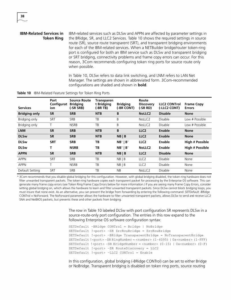
IBM-Related Services inToken Ring
IBM-related services such as DLSw and APPN are affected by parameter settings in the BRidge, SR, and LLC2 Services. Table 10 shows the required settings in source route (SR), source route transparent (SRT), and transparent bridging environments for each of the IBM-related services. When a NETBuilder bridge/router token-ring port is configured for both an IBM service such as DLSw and transparent bridging or SRT bridging, connectivity problems and frame copy errors can occur. For this reason, 3Com recommends configuring token ring ports for source route only when possible.
In Table 10, DLSw refers to data link switching, and LNM refers to LAN Net Manager. The settings are shown in abbreviated form. 3Com-recommended configurations are shaded and shown in bold.
The row in Table 10 labeled DLSw with port configuration SR represents DLSw in a source-route-only port configuration. The entries in this row expand to the following Enterprise OS software configuration syntax:
SETDefault -BRidge CONTrol = Bridge | NoBridgeSETDefault !<port> -SR SrcRouBridge = SrcRouBridgeSETDefault !<port> -BRidge TransparentBridge = NoTransparentBridgeSETDefault !<port> -SR RingNumber = <number> (1–4095) | 0x<number> (1-FFF)SETDefault !<port> -SR BridgeNumber = <number> (0-15) | 0x<number> (0-F)SETDefault !<port> -SR RouteDiscovery = LLC2SETDefault !<port> -LLC2 CONTrol = Enable
In this configuration, global bridging (-BRidge CONTrol) can be set to either Bridge or NoBridge. Transparent bridging is disabled on token ring ports, source routing
Table 10 IBM-Related Feature Settings for Token Ring Ports
Services
Port Configuration
Source Route Bridging (-SR SRB)
Transparent Bridging (-BR TB)
Bridging (-BR CONT)
Route Discovery (-SR RD)
LLC2 CONTrol (-LLC2 CONT)
Frame Copy Errors
Bridging only SR SRB NTB B NoLLC2 Disable None
Bridging only SRT SRB TB B NoLLC2 Disable Low # Possible
Bridging only T NSRB TB B NoLLC2 Disable Low # Possible
LNM SR SRB NTB B LLC2 Enable None
DLSw SR SRB NTB NB | B LLC2 Enable None
DLSw SRT SRB TB NB* | B* LLC2 Enable High # Possible
DLSw T NSRB TB NB* | B* NoLLC2 Enable High # Possible
APPN SR SRB NTB NB | B LLC2 Disable None
APPN SRT SRB TB NB | B LLC2 Disable None
APPN T NSRB TB NB | B LLC2 Disable None
Default Setting SRT SRB TB NB NoLLC2 Disable None
* 3Com recommends that you disable global bridging for this configuration. However, with global bridging disabled, the token-ring hardware does not filter unwanted transparent packets. The token-ring hardware copies each transparent packet for processing by the Enterprise OS software. This can generate many frame copy errors (see Token Ring Frame Copy Errors below for more information.) If you are seeing many Frame Copy Errors, consider setting global bridging on, which allows the hardware to learn and filter unwanted transparent packets. Since DLSw cannot block bridging loops, you must insure that none exist. As an alternative, you can prevent the bridge from forwarding by entering the following command: SETDefault -BRidge CONTrol = NoForward. The NoForward parameter allows the hardware to filter unwanted transparent packets, allows DLSw to send and receive LLC2 SNA and NetBIOS packets, but prevents these and other packets from bridging.
IBM Protocols and Services Notes 39
and route discovery are configured, bridge numbers must be unique for each bridge/router on the same ring, and LLC2 is enabled on token ring ports.
Token Ring Frame Copy Errors
For transparent bridge or source route transparent configurations, token ring end systems may generate a small number of MAC frame copy error reports when the NETBuilder II bridge/router token ring interface is initializing or when the bridge/router ages out a MAC address from its bridge table.
For the bridge/router to learn the MAC addresses of transparent end systems on the token ring, it copies a packet with an unknown source address and sets the address-recognized (A) and frame-copied (C) bits in the Frame Status (FS) field. A problem occurs when the FS (A) and (C) bits have been set and the destination of the frame is an end system on the local ring. The destination end system expects the (A) and (C) bits to be zeros. When it receives a frame with these values already set, it reports an error. The end system counts these errors and accumulates them until the MAC layer Soft Error Report Timer period is reached; the default is two seconds. A MAC Report Error packet is then sent to the Ring Error Monitor (REM) Network Management entity.
A source route only configuration eliminates frame copy errors. Frame copy errors do not occur in source route only environments when the NETBuilder bridge/routers are configured properly. This is because the NETBuilder bridge/router hardware filters source-routed packets based on the route information field, not the MAC address. If the bridge/router is configured for source route only, it never copies frames destined for a station on the local ring. Frame copy errors can be eliminated by running in source-route-only mode.
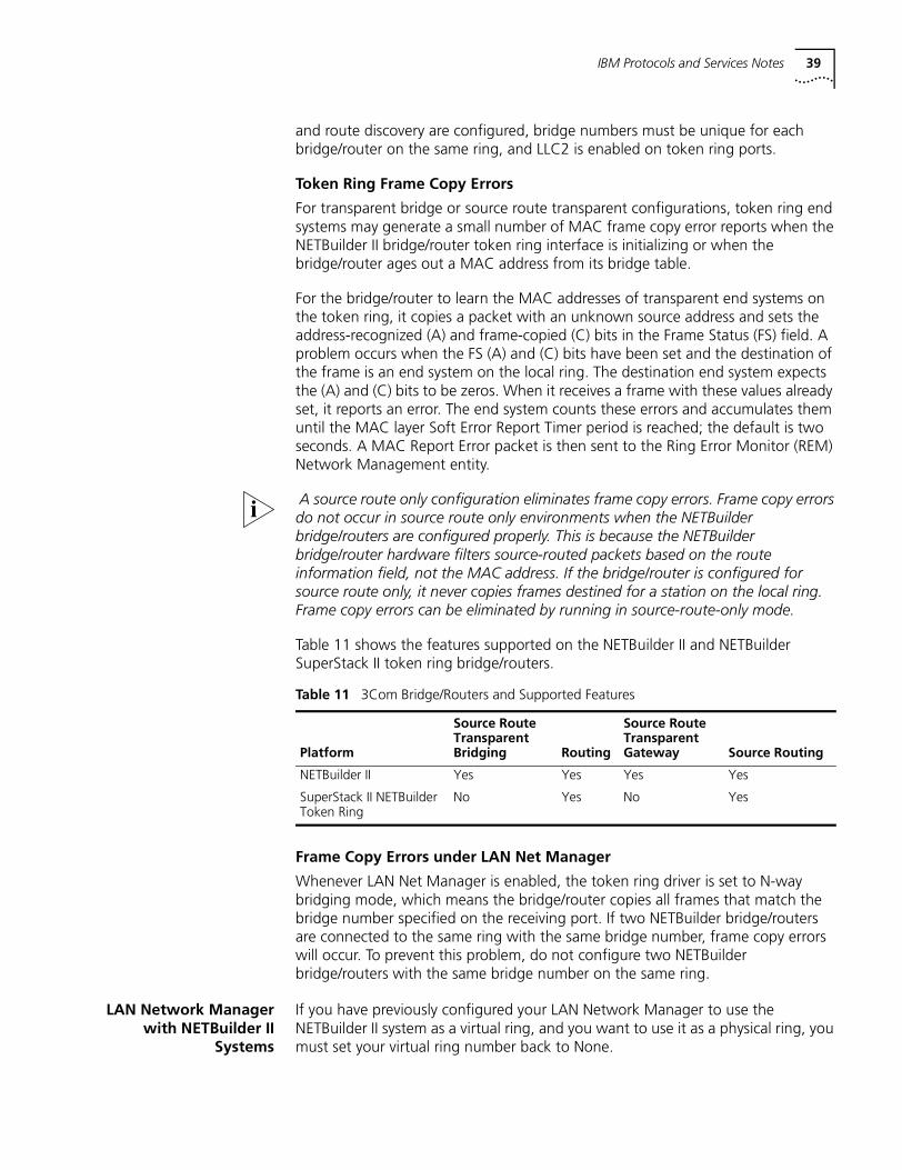
Table 11 shows the features supported on the NETBuilder II and NETBuilder SuperStack II token ring bridge/routers.
Frame Copy Errors under LAN Net Manager
Whenever LAN Net Manager is enabled, the token ring driver is set to N-way bridging mode, which means the bridge/router copies all frames that match the bridge number specified on the receiving port. If two NETBuilder bridge/routers are connected to the same ring with the same bridge number, frame copy errors will occur. To prevent this problem, do not configure two NETBuilder bridge/routers with the same bridge number on the same ring.
LAN Network Managerwith NETBuilder II
Systems
If you have previously configured your LAN Network Manager to use the NETBuilder II system as a virtual ring, and you want to use it as a physical ring, you must set your virtual ring number back to None.
Table 11 3Com Bridge/Routers and Supported Features
Platform
Source Route Transparent Bridging Routing
Source Route Transparent Gateway Source Routing
NETBuilder II Yes Yes Yes Yes
SuperStack II NETBuilder Token Ring
No Yes No Yes
40
LLC2 Frames and PPP LLC2 frames are not sent or received over PPP unless global bridging is enabled using the SETDefault -BRidge CONTrol = Enabled command. You must enable LLC2 on the port using:
SETDefault !<port> -LLC2 CONTrol = Enabled.
If bridging is enabled and you do not want bridging, either set the -BRidge CONTrol parameter to NoForward, or disable bridging on individual ports by setting the following command:
SETDefault -BRidge TransparentBridge = NoTransparentBridge
Maximum BSC LineSpeed
For V.35 and RS-232 links, the maximum baud rate supported for BSC traffic is 38.4. If the baud rate is higher, BSC traffic suffers errors and retransmissions.
SHDLC Half-DuplexMode
SHDLC does not support physical half-duplex mode.
SDLC SDLC requires the following:
■ XID spoofing must be turned on if the IBM Communication Manager is used for 3270 communications and is defined as a PU type 2.0. Use the following syntax:
SETDefault !<PU name> -SDLC CUXId = <value> (8 Hexadecimal digits)SETDefault !<PU name> -SDLC CUXidDefined = Yes
■ SDLC end-to-end through local switching (conversion to a single LLC2 LAN connection between two NETBuilder bridge/routers) requires different virtual ring numbers in the LLC2 Service.
SDLC Adjacent LinkStations for APPN
When you configure SDLC adjacent link stations for APPN, if an active link becomes inactive and you change the port definition using the PortDef parameter, the link remains inactive. If you try to reactivate the link using the SET -APPN LinkStaCONTrol command, the link reactivates within 30 seconds. To activate the link immediately, you must enable the APPN port using the SET -APPN PortControl = Enable command.
Source RouteTransparent Bridging
Gateway (SRTG)Interoperability
The NETBuilder II bridge/router cannot interoperate with Cisco or IBM routers if the NETBuilder bridge/router is configured using Source Route Transparent Gateway (SRTG) with Source Route bridging on the token ring LAN port and Transparent Bridging on the PPP or Frame Relay WAN ports. In this configuration, the NETBuilder II bridge/router is sending using PPP bridge encapsulation 802.5 token ring format, while the IBM 6611 and the Cisco 400 router are using PPP bridge encapsulation 802.3 Ethernet format.
SDLC Ports and NetViewService Point
An SDLC port defined for NetView Service Point cannot be used for SDLC-to-LLC2.
UI Response Time WithLarge SDLC
configuration
When NETBuilder bridge/router is configured with many SDLC PUs, SETDefault commands may take a long time to complete. Using the Defrag command to streamline the flash that contains the configuration files can fix the problem.
VTAM ProgramTemporary Fixes
VTAM Program Temporary Fixes (PTFs) are required on a mainframe when APPN DLU services are used. Mainframe network management (NetView) services will not function for downstream physical units (PUs) if the PTFs are not installed.
ATM Services Notes 41
VTAM Version 4.2 requires PTF #UW20787. VTAM Version 4.3 requires PTF #UW20788.
Visible symptoms of this problem can be seen as a lack of network management data for PUs that are downstream of a NETBuilder II bridge/router using APPN DLU services. The NetView message “AAU251I AAUDRTIB 02 UNEXPECTED SENSE CODE X'1002' ENCOUNTERED FOR TARGET=pu_name” is printed in the log file when this problem occurs.
ATM Services Notes This section describes notes, cautions, and other considerations to be aware of when using the Enterprise OS software with ATM services. The topics are presented in alphabetical order.
ATM Emulated LANs Enterprise OS software supports a system maximum of 32 ATM emulated LANs.
ATM LAN EmulationClients and Large 802.3
Frames
This release of LAN emulation software does not support large 802.3 frame encapsulation as specified in the LANE standard 1.0. When IP routing is used from FDDI to an emulated LAN, packets larger than 1500 are sent fragmented per IP fragmentation rules.
ATM Connection Table In a LAN Emulation environment with many LAN Emulation Servers (LESs), a performance drop may occur when the NETBuilder bridge/router is able to connect to the LAN Emulation Configuration Server (LECS), but many of the LESs are down or unreachable. Disabling the ETHATM virtual ports corresponding to the unreachable LESs will alleviate this situation.
Deleting ATM Neighbors Bridge ATM Neighbors must be deleted before the associated virtual ports can be deleted.
Source-RouteTransparent Gateway
The source-route transparent gateway is not currently supported on ATM LAN emulation ports.
WAN Protocols and Services Notes
This section describes notes, cautions, and other considerations to be aware of when using the Enterprise OS software with WAN protocols and services. The topics are presented in alphabetical order.
ACCM Not Configurable The ACCM (Async Control Character Map) used for Async PPP cannot be configured. During LCP negotiation, the NETBuilder bridge/router always proposes an ACCM of all zeros and agrees to whatever the peer negotiates.
Asynch Tunnelling onSerial Ports
For best results, set the LineType parameter to Leased and set the SuperStack II NETBuilder bridge/router model 32x connector type for the universal port to RS-232. For the path to come up, the bridge/router must see a DTR or DSR control signal from the device. Or, if the device does not generate a control signal, a loopback connector should be used to supply the control signal.
Automatic LineDetection
When set to the value of Auto, the -PATH LineType parameter first attempts to bring up the path as a leased line by raising the data terminal ready (DTR) signal. If the path comes up but a DTR-base dial modem is attached to the path, the modem does not hang up until brought down manually with the HangUp command. To avoid this situation, set the -PATH LineType parameter to Dialup.
42
Auto Start-up Does NotInclude Async
Automatic detection of the line type (LineType=Auto) and link protocol (OWNer=Auto) do not include recognition of Async PPP and AT dial. For Async PPP and AT dial (which must be used together), the following parameters must be explicitly configured:
-PATH LineType=Dialup-PATH DialMode=ATdial-PATH ExDevType=Async-PORT OWNer=PPP
The PATH service parameter TransferMode should not be changed from its default value of AUto. Other settings of this parameter are reserved for future extensions.
Bandwidth-on-Demand Timer
Precedence
Two PORT Service parameters are used to configure bandwidth-on-demand ports. The DialIdleTime parameter sets the time in seconds before all dialup lines in a port are disconnected if the port is not in use. The DialSamplPeriod parameter sets the time (in seconds) to sample before taking an action to bring additional paths up or down, based on traffic load for bandwidth-on-demand. The value specified for the DialIdleTime parameter takes precedence over the value specified for the DialSamplPeriod parameter.
Baud Rates for WANPorts in DCE Mode
The following baud rates are supported in DCE mode (synchronous, internal clocking):
If you configure a baud rate that is different from those listed, the system will fall back to the nearest lower supported rate.
BSC Cabling andClocking
The data communication equipment (DCE) cable for SuperStack II bridge/routers should be 07-264-000-01 (rev. 1) to work in BSC internal clocking mode.
Changing the TransferMode Parameter Default
Value
The PATH service parameter TransferMode should not be changed from its default value of AUto. Other settings of this parameter are reserved for future extensions.
CompressionRequirements
Compression must use the same configuration at both ends of the connection. If one side of a connection is configured as per-packet and the other is configured as history, the PPP link does not come up.
■ 1200 ■ 112 K
■ 1800 ■ 128 K
■ 2400 ■ 256 K
■ 3600 ■ 384 K
■ 7200 ■ 448 K
■ 9600 ■ 768 K
■ 19 K ■ 1344 K
■ 38 K ■ 1536 K
■ 56 K ■ 1580 K
■ 64 K ■ 2048 K
WAN Protocols and Services Notes 43
Dial Idle Timer The dial idle timer is not accurate and it will take a client longer to idle out than is configured. For a 180 second dial idle time it takes approximately 8.5 minutes for the client to idle out if no traffic is ever sent. To workaround this problem, disable bootp on !0 by entering the following command:
Setd !0 -bootp control=disable"
Disaster Recovery onPorts Without Leased
Lines
The Port Service DialControl parameter controls port attributes for a dial-up port in the event the bandwidth set for a leased line drops below what has been set as the normal bandwidth. Setting this parameter to DisasterRecovery for a port without leased lines prevents port idle out.
DTR Modems DTR modems should not be configured as a dynamic path and a dial pool.
Dynamic Paths Dynamic paths might not be released back into the dial pool from the port if an incoming call arrives during a disconnect state. If the SHow -POrt PAths command indicates that a path from the dial pool is attached to a port but is no longer in use, it can be released by re-enabling the port.
Frame Relay CongestionControl
The current implementation of Frame Relay congestion control requires that you set the committed burst size (Bc) and the committed information rate (cir) to the same value so that the time interval (Tc) equals 1 second using the formula Tc= <Bc>/<cir>. If Tc is not 1 second, the Frame Relay frames may be erroneously dropped due to the incorrect calculation of the throughput rate threshold.
History-BasedCompression
Negotiation Failure
If you are using history-based compression on a line with excessive errors and the negotiation attempts exceed the retry count, the device must be rebooted to clear the condition and reset the retry count.
History Compression NotAllowed With Async PPP
A port using Async PPP (AT dial) cannot be configured for history compression. The user interface will not prevent you from configuring the port for history compression, however, if history compression is selected the path will not come up.
Multilink PPPConfigurations
Multilink PPP (MLP) is supported for multiple WAN links connected to the same port running PPP.
When configuring MLP:
■ For maximum performance on a NETBuilder II bridge/router, 3Com recommends that similar hardware interface types be configured for each MLP bundle. For instance, bundle HSS modules with HSS modules, and bundle HSS 3-port module links with HSS 3-port module links.
■ For the best performance, use MLP on interfaces with matched line speeds. Avoid mismatched baud rates of ratios greater than 10 to 1 for bundled links.
■ If your baud rate ratios on two links are greater than 4 to 1, the MLP feature automatically turns off fragmentation. For baud ratios of less than 4 to 1, you may choose to turn off fragmentation for performance considerations. Turn off fragmentation using the MlpCONTrol parameter in the PPP Service.
■ MLP does not support the HSSI module.
■ Before you re-enable a port running MLP, disable the port and allow the remote port to go down. This action prevents loss of packet sequence numbers
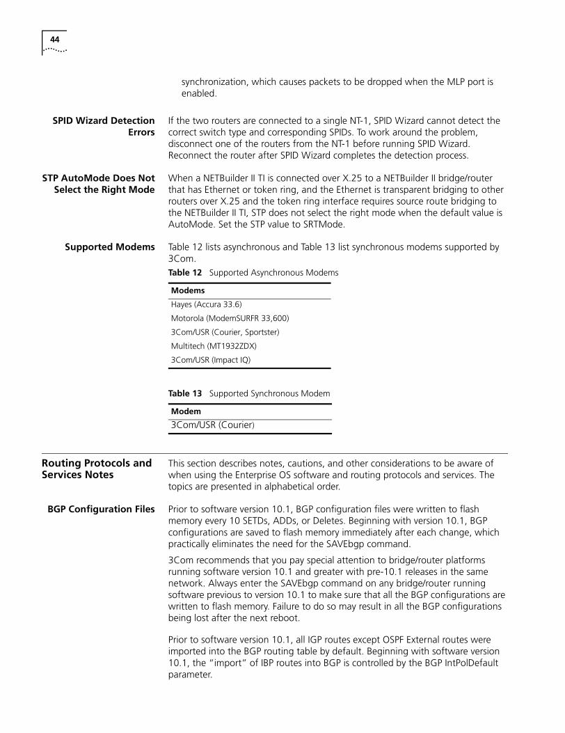
44
synchronization, which causes packets to be dropped when the MLP port is enabled.
SPID Wizard DetectionErrors
If the two routers are connected to a single NT-1, SPID Wizard cannot detect the correct switch type and corresponding SPIDs. To work around the problem, disconnect one of the routers from the NT-1 before running SPID Wizard. Reconnect the router after SPID Wizard completes the detection process.
STP AutoMode Does NotSelect the Right Mode
When a NETBuilder II TI is connected over X.25 to a NETBuilder II bridge/router that has Ethernet or token ring, and the Ethernet is transparent bridging to other routers over X.25 and the token ring interface requires source route bridging to the NETBuilder II TI, STP does not select the right mode when the default value is AutoMode. Set the STP value to SRTMode.
Supported Modems Table 12 lists asynchronous and Table 13 list synchronous modems supported by 3Com.
Routing Protocols and Services Notes
This section describes notes, cautions, and other considerations to be aware of when using the Enterprise OS software and routing protocols and services. The topics are presented in alphabetical order.
BGP Configuration Files Prior to software version 10.1, BGP configuration files were written to flash memory every 10 SETDs, ADDs, or Deletes. Beginning with version 10.1, BGP configurations are saved to flash memory immediately after each change, which practically eliminates the need for the SAVEbgp command.
3Com recommends that you pay special attention to bridge/router platforms running software version 10.1 and greater with pre-10.1 releases in the same network. Always enter the SAVEbgp command on any bridge/router running software previous to version 10.1 to make sure that all the BGP configurations are written to flash memory. Failure to do so may result in all the BGP configurations being lost after the next reboot.
Prior to software version 10.1, all IGP routes except OSPF External routes were imported into the BGP routing table by default. Beginning with software version 10.1, the “import” of IBP routes into BGP is controlled by the BGP IntPolDefault parameter.
Table 12 Supported Asynchronous Modems
Modems
Hayes (Accura 33.6)
Motorola (ModemSURFR 33,600)
3Com/USR (Courier, Sportster)
Multitech (MT1932ZDX)
3Com/USR (Impact IQ)
Table 13 Supported Synchronous Modem
Modem
3Com/USR (Courier)
Network Management System and Services Notes 45
CPU Utilization with XNSProtocol
When the PathBuilder S5xx switch is configured for 2048 tunnels and XNS protocol, very high CPU utilization will occur.
IPX to Non-IPXConfiguration Error
A mechanism does not exist to prevent adding a path from a non-IPX routing port to an IPX routing port. If this situation occurs, the router stops routing IPX traffic, even though the primary port has been up the whole time. To restart IPX routing, re-enable the port.
IPX Routing, RouteReceive and Route
Advertisement Policies
When you route IPX over a Frame Relay meshed topology and configure the SAP Route Receive and Route Advertisement policies on the Frame Relay port, these policies do not take effect until the SAP table is flushed.
Managing IP AddressAssignment
When assigning IP address to virtual ports of directly connected networks, it is important to ensure that the assigned address is valid. As LCP supports multiple Network Control Protocols (NCPs), IP does not verify that the address is valid before bringing the port state up or down, as there may be other protocols which are utilizing that port. It is possible to have an UP port state, yet have a lack of IP connectivity.
NAT Service - Many toOne Outbound
Translation
NAT Many to One Outbound does not translate properly when multiple addresses, on LHS, are specified using comma (,) notation. But NAT Many to One Outbound translates properly when multiple addresses, on LHS, are specified in 10.3.1.0/24 notation.
NAT Service - TCP/UDPPort Mappings
When the NETBuilder bridge/router is configured to use TCP/UDP Port Mapping from port 23 (Telnet) to any other port number, the first command executed over the session will fail due to extra characters inserted into the command string. All subsequent commands issued for that session will succeed. If you encounter this problem, execute the command again.
OSPF RouteAdvertisement
If your network is expecting more than 4000 OSPF routes you need to set the ospfholdtime variable to 30.
RouteDiscovery If RouteDiscovery is enabled on all protocols (-SR RouteDiscovery = All), in the maximum packet forwarding rate drops significantly during route discovery. 3Com recommends that you enable RouteDiscovery only for the protocols you use. Increasing the value of the -SR HoldTime parameter minimizes the drop in forwarding rate for these protocols.
VRRP Configuration VRRP cannot coexist with DECnet, LAA, OSI, or IPv6.
Network Management System and Services Notes
This section describes notes, cautions, and other considerations to be aware of when using the Enterprise OS software when working with network management system services. The topics are presented in alphabetical order.
ASCII Boot When using the ASCII Boot feature on a NETBuilder II bridge/router with intelligent I/O modules or a PathBuilder S5xx series switch, configuration commands that apply to the physical ports on the intelligent I/O modules or to the physical ports on the PathBuilder may not get configured correctly if they are the first commands executed in the boot.cfg file. There is a small timing window where the commands affecting the physical ports will not execute successfully because the software drivers have not finished initializing the ports.
46
This problem can be avoided by either including a PAuse command at the beginning of the boot.cfg file to delay the execution of the first configuration command by a few seconds or by putting the configuration commands that do not apply to the physical ports at the beginning of the boot.cfg file. The intelligent I/O modules on the NETBuilder II bridge/router are the HSS 4-Port WAN Module, the MP ATMLink Module, the MP Ethernet 6-Port 10BASE-FL Module, and the HSS 8-Port BRI Module. Support for the PAuse command by the ASCII Boot feature (and LoadConfigs) is new with the Enterprise OS software version 11.3.
Boot CycleContinuous Loop
If the OfficeConnect bridge/router fails to complete the boot cycle and enters a boot cycle loop (for example, if the boot image is corrupted), press the ESC key to interrupt the boot cycle and enter monitor mode.
BootP Server andAutostartup
To use the Enterprise OS software version 11.3 Autostartup feature, you must upgrade the remote node, the central site, and if you are using the 3Com BootP server, you must upgrade that as well. Autostartup supports a non-3Com BootP server if the remote node is identified by its MAC address.
Bootptab File The 3Com BOOTP Server for Windows does not read the bootptab file for any date greater than 2000. The problem resides in Microsoft's system libraries. A patch can be downloaded from Microsoft. This patch can be found at the following URL:
http://www.microsoft.com/windows95/downloads/default.asp
Capturing Commands toboot.cfg File
When using Capture to save commands to the boot.cfg, the commands are not immediately written to the boot.cfg file. A system crash or reboot may occur at a time when commands that have been executed have not been written to the boot.cfg file causing these commands to be lost.
Change Configurationand Diagnostic Menu
The options on the Change Configuration and Diagnostic menu do not apply to the model 1x1 OfficeConnect bridge/router because ISDN ports are not present on this system.
CPU Utilization Statistic For the NETBuilder Remote Office bridge/routers, the CPU utilization statistic indicates a high percentage of utilization regardless of actual use. CPU utilization is displayed on the first line of the response to the SHow STATistics command. This incorrect display statistic will be fixed in a future release of the Enterprise OS bridge/router software.
File System Error Occasionally a false file system error message telling you to format and restore configuration files will appear on the console. These false errors appear when the background processing in the NETBuilder bridge/router is performing file operations and you attempt a write operation (such as a SETDefault command, DEFRag command, and FORMAT command). In these programmatic lockouts rather than media related error conditions, the flash file system will NOT need to be reformatted. Examining the results of the attempted command (such as SHow to examine the results of the attempted SETDefault) can indicate whether the file system error is a false indication or not.
Firmware Configuration To select BootP as your Address Discovery protocol, you must set all five IP address options to None.
Network Management System and Services Notes 47
Firmware Update The bridge/router updates firmware as part of its software boot process. In some cases, some text is displayed during the firmware upgrade process, which appears similar to the following:
>>>>updating firmware boot bank A>>>>famd_blk_erase: block addr less than 512K: 0x10000>>>>famd_blk_erase: block addr less than 512K: 0x20000>>>>Firmware boot bank update is complete.
These messages do not indicate a problem and can be ignored.
Multiple Paths to BootPServer
Multiple paths to a BootP server may cause a BootP reply to fail. If a BootP reply is transmitted by a BootP server and not received by the router, flush the IP Routing table and re-enable BootP on the port waiting for the IP address. BootP must be re-enabled before route update are received.
Remote AccessDefault Change
To increase network security, the default value for the NetAccess parameter in the SYS Service is set to NoRemote. This means that by default, no remote connection attempts will be accepted by the bridge/router. If you are accustomed to or want to use remote access, you must specifically set the value of the NetAccess parameter to Remote.
SchedulerRunOnBootFail
Completion
When RunOnBootFail is specified, event-based macro execution (EBME) is enabled when the primary connections fail to establish within 5 minutes after the switch boots. After the initial 5 minutes, PortDown event processing happens at the rate of approximately one port per second. When the PathBuilder S5xx series switch is configured for 2048 virtual ports it takes about 45 minutes after the system initializes for the RunOnBootFail processing to be completed on all ports.
V.25bis Modem Setup If you are using a V.25bis modem with a NETBuilder boundary routing leaf node, and you configure the line type explicitly as dial rather than auto, be certain to also set the DialMode to V.25bis rather than use the default of DTR.
Web LinkDocumentation Path
When you set the DocumentPath parameter in the WebLink service to a local file, drive C for example (“file:///c:”), the Web Link assumes that access to the NETBuilder bridge/router takes place only from the computer to which the file is local. If Web Link is used from any other computer, the browser looks on its local “C” drive for the help pages. If the computer is a UNIX machine and these files are not present as expected, unpredictable browser behavior will result.
Web Link Login Support When you access the Web Link application for the first time, you are prompted to enter a username and password. This username and password remains valid on the NETBuilder bridge/router for two hours. Because most browsers cache user login information, it is recommended that you log out of Web Link by selecting the “Logout” icon on the home page.
Zmodem Time Out A Zmodem file transfer from a PC to a SuperStack II or OfficeConnect bridge/router can take a long time. To minimize the possibility that the PC Zmodem software will time out during the download, run the DEFRag command on the SuperStack II bridge/router before beginning the file transfer. The DEFRag command reclaims dirty space in flash memory. Dirty space is memory that has been written on and cannot be used again until it has been erased.
48
VPN Protocols and Services Notes
This section describes notes, cautions, and other considerations to be aware of when using the Enterprise OS software with VPN protocols and services. The topics are presented in alphabetical order.
ACE Security Server When interoperating with the ACE Security Server for Token-based login support, you may need to change the RAS Retransmit Timer value to a higher value (for example, 7) to prevent access-request time-outs.
Total Control Securityand Accounting Server
Availability
The Total Control™ Security and Accounting Server provides call authentication, authorization, and accounting for your Enterprise OS devices. At the time of publication of these release notes, the required version number of the SAS server was unavailable. To determine the required version, refer to the online version of these release notes available on the 3Com website:
http://infodeli.3com.com/infodeli/tools/bridrout/index.htm
Microsoft MPPE Patchesand Updates
Microsoft has acknowledged performance problems with their original implementation of MPPE. You should use MSDUN1.2c or later for Windows 95 and apply Hot Fixes in article Q162230 for Windows NT. Contact your Microsoft service provider for additional information and updates when they become available.
PPTP Tunnel SecurityValidation
Authentication problems may occur when connecting a Windows 95 or NT client via a Total Control™ hub to a NETBuilder II bridge/router where the Total Control hub is setting up a PPTP tunnel to the bridge/router.
This problem is a combination of the security protocol between the client and the LS (in this case the Total Control Hub) and the time it takes to validate a Radius request on the Radius server. In addition, the setting of the DefaultAptCtl parameter needs to be considered because this determines which security protocol the NETBuilder bridge/router will use.
If the client and the LS negotiate to use PAP, the client will send PAP configure requests but at that time the LS is busy setting up the PPTP tunnel and will forward the PAP requests to the NETBuilder bridge/router. The bridge/router by default sends CHAP challenge to the client and normally the client responds immediately. Then the NETBuilder bridge/router sends a request to the Radius server for validation.
If there is another PAP request from the client to the bridge/router while the bridge/router is waiting for validation from the Radius server, the bridge/router will send a PAP NAK to the client and the session is terminated. If the CHAP success message is received before the next PAP message, the PAP message is discarded and the connection is established.
Solutions include disabling CHAP on the NETBuilder DAC or disabling PAP between the client and the LS.
This situation does not arise when the NETBuilder bridge/router is using internal security because it is fast enough to check the CHAP response before the next PAP message is generated.
Platform Notes 49
Windows NT MS-CHAPAuthentication
Although the 11.3 RAS service now supports 64 character user names and passwords, any Windows NT user with a password greater than 14 characters long will fail MS-CHAP authentication. Per the IETF MS-CHAP v2 draft current versions of Windows NT limit passwords to 14 characters.
Platform Notes This section describes the supported PC flash memory cards, approved DRAM SIMMS, notes, cautions, and other considerations to be aware of when using the Enterprise OS software on the various NETBuilder bridge/router and PathBuilder platforms. The topics are presented in alphabetical order.
Approved DRAM SIMMs Table 14 lists 3Com–approved vendors of the 32 MB DRAM SIMM for upgrading the NETBuilder II DPE 40 module.
Supported PC FlashMemory Cards
Table 15 lists 3Com-approved vendors of the PC flash memory card.
The 20 MB flash memory card has a formatted capacity of 19.86 MB. For dual image and full dump capability, 3Com recommends using a 20 MB card used in the NETBuilder II bridge/router.
You can also purchase the blank flash memory card from 3Com:
■ DPE 20 MB card is 3C6086
Line Error Reporting onPathBuilder S5xx Series
Switch Statistics Display
The PathBuilder series switch reports FSI CRCs under the path statistics. This entry reflects line errors after hardware error assisted recovery has taken place. The number of actual line errors present before hardware error assisted recovery has taken place may be much higher.
T3 Bandwidth Limitation Due to a driver limitation you cannot combine two T3 paths to double the bandwidth.
MBRI Ownership DuringBoard Swapping
Port ownership and port/path naming inconsistencies can occur as MBRI boards are swapped in and out of a NETBuilder II bridge/router chassis. Replacing an MBRI board with a non-MBRI board in the same slot requires that the NETBuilder II bridge/router be rebooted. After the bridge/router is rebooted, there are no port/path naming problems.
Multiport MBRI ModuleSNMP Management
The Multiport MBRI module cannot be configured using SNMP.
Table 14 3Com-approved DRAM SIMMs
Size Vendor and Description Part Number
32 MB
72-pin 8Mx32 60 ns page mode
NEC MC428000A32B-60
Toshiba THM328020S-60
Toshiba THM328020B5-60
Table 15 3Com-approved 20 MB Flash Memory Cards
Vendor and Description Part NumberIntel Series 2 iMC020FLSA
Intel Series 2+ iMC020FLSPAMD Series D AmC020DFLKA

50
Token Ring+ Modules The maximum physical frame size that can be forwarded by the Token Ring+ modules with Enterprise OS software is 4,500 bytes. This software limitation affects routing, source route bridging, and transparent bridging.
Token Ring AutoStart-up
The Token Ring and Token Ring+ modules may enter the ring at the wrong speed with certain MAU or station configurations. You can manually configure the -PATH BAud value to 16,000 or 4,000 to avoid this situation.
USING ENTERPRISE OS SOFTWARE UPDATE PAGES
This section includes update pages with changes and additions to Using Enterprise OS Software, software version 11.2. These changes relate to the feature enhancements in Enterprise OS software version 11.3.
Place the update pages at the front of each specified chapter.

52
22
CONFIGURING IPSECThis chapter describes how to configure the IP Security Protocol (IPSec) on your IP router. IPSec provides security at the network layer. Because IPSec is integrated into IP itself, IPSec adds security to any link, regardless of the application used.
IPSec can be used in conjunction with a tunneling protocol. The protocols that can be used for tunneling are: PPTP, L2TP, IPIP. See the Configuring L2Tunnel Connections chapter for more information about PPTP/L2TP.
It is recommended that IPSec control or the PORT service control be disabled while configuring policies and enabled only after all IPSec policy configuration has been completed.
For conceptual information, see “How IPSec Works” later in this chapter.
Configuring IPSec The procedures in this section describe how to define the basic components of IPSec. IPSec can be configured using manual policies and keys or using dynamic policies. Also, it can be configured in either transport mode or tunnel mode.
Transport Mode Transport mode security associations are used to protect traffic that is viewed on an end system from an IPSec perspective. For example, it can be used with PPTP/L2TP/IPIP tunnels or to serve network management traffic like Telnet or SNMP.
Tunnel Mode Tunnel mode security associations are used to protect IP traffic forwarded by the router on IPSec tunnel ports.
Creating Manual Policies An IPSec policy consists of an action, the packet types that require the action, and the source and destination addresses between which the action occurs. The following seven actions are supported:
■ Action AhXport
■ Action EspXport
■ Action AhEspXport
■ Action EspAuthXport
■ Action AhTunnel
■ Action EspAuthTunnel
■ Action EspTunnel
54 CHAPTER 22: CONFIGURING IPSEC
Configuring ManualSecurity Policies
To configure IPSec using manual policies, follow these steps:
1 Define a policy using ManualPolicy.
2 Define the manual keys using the KeySet parameter.
3 Bind the information together using the ManualKeyInfo parameter.
To configure a manual security policy, use:
ADD !<portlist> manualPOLicy <policy_name> <action> (DEFault |{<filters> <src_ipaddr/mask>
(<dst_ipaddr/mask> | DYNamic)})[<encrypt_alg>] [<auth_alg>]
<action>: AhEspXport | AhTunnel | AhXport |EspAuthTunnel | EspAuthXport | EspTunnel | EspXport
<filters>: ANY | (GRE, ICMP, OSPF,TCP[(<port>,<port>)...up to 16 pairs],UDP[(<port>,<port>)...up to 16 pairs])
<encrypt_alg>: 3DES | 3DES2key | DES | RC5 | NULL<auth_alg>: MD5 | SHA
<port>: 16553 5 | * | Archie | DNS | Finger | FTP | FTPData |Gopher | HTTP | NFS | NNTP | NTP | POP2 | POP3 |
PortMap | RIP | SMTP | SNMP | SNMPtrap | Syslog |Telnet | WAIS
The default for encrypt_algorithms is DES. The default for auth_algorithms is MD5.
Creating Key Sets
To create a key set, use:
ADD -IPSEC KeySet <key_set_name> [EncryptKey (“<encrypt_key>” |“%<encrypt_key>”)] [AuthKey (“<auth_key>” | “%<auth_key>”)]
The encrypt_key and auth_key must match the values on the peer system at the other end of the security association.
<key_set_name> is a name you assign to the key set you are adding.
<encrypt_key> and <auth_key> can be 1 to 128 bytes entered as either ASCII text strings or as a series of hexadecimal digits. See “Configuring Manual Key Information” next for more information about key set usage.
To delete a key set, use:
DELete -IPSEC KeySet [<key_set_name> | ALL]
For example, to create a new encryption key set, enter:
ADD !1 IPSEC KeySet esp_key EncryptKey “hello124”
To create a key set for both encryption and authentication, enter:
ADD !1 IPSEC KeySet espah_key EncryptKey “hello124” AuthKey “world236”
Configuring IPSec 55
Configuring Manual Key Information
The ManualKeyInfo parameter binds manual keying information to an IPSec policy. Only one ManualKeyInfo command can be applied to each policy. To configure manual key information, use:
SETDefault !<portlist> -IPSEC ManualKeyInfo = <policy_name>(<key_set_name> | NONE) [SpiEsp <spi_in> <spi_out>] [SpiAh <spi_in><spi_out>]
A Security Parameters Index (SPI) value is used in conjunction with the destination address to identify a particular security association which represents a set of agreements between senders and receivers on a key, on an encryption or authentication algorithm, and on SPI numbers.
A key is specified using the ADD -IPSEC keyset command. It is later bound to an IPSec policy when an add IPSec policy command is entered. The key set and policy command can be used in any order. Binding takes place when the second of the two commands is issued.
When the key is entered no particular length restriction is applied. Keys can be entered as either ASCII text or hex values in the range of 1 to 128 bytes. When a key is bound, certain length restriction are applied. The required key length depends on the Enterprise OS software package used.
All packages reject keys that are too short for their encryption transform and generate error messages. The xE packages truncate long keys to 7 bytes, and the xS packages truncate long keys to 24 bytes, with appropriate warning messages.
For compatibility with previous software versions that did not enforce key lengths, it is possible to enter a DES key as an 8-byte hex value with the appropriate number of null characters at the end. For example, a DES key of abcd should now be entered: %6162636400000000
To change the manual keying information, you must first delete the information using NONE as the key set name, then add the new information using SETDefault. For example, to create a security association and bind a key set to a corresponding encryption policy, enter:
SETDefault !1 -IPSEC ManualKeyInfo = esp_pol esp_key SpiEsp 500 501
To create a security association of an encryption and authentication policy, enter:
SETDefault !1 -IPSEC ManualKeyInfo = ah espah_pol espah_key SpiEsp 600 601SpiAh 700 701
When keys are displayed using the SHow -IPSEC Keyset command, the MD5 hash of the key is displayed rather than the key itself. This allows you to compare keys for equality without exposing the actual key value. The length of the key is also displayed, since the hash is always a 32-digit hex value.
During boot, any previously configured policies and keys are bound together. The various length restrictions are applied during this binding, so that you cannot use keys that are longer than the package supports. At boot-time, binding accepts DES keys that are shorter than 8 bytes and the system generates a warning rather than an error.
56 CHAPTER 22: CONFIGURING IPSEC
Configuring IPSec with Manual Policy
For example, to protect all TCP and UDP traffic between router 1 (170.0.0.1) and router 2 (180.0.0.1) on port 1 with an IPSec encryption policy, follow these steps:
1 Create an encryption policy with an unique policy name by entering:
ADD !1 -IPSEC manualPOLicy esp_pol EspXport tcp,udp 170.0.0.1 180.0.0.1
2 Create a key set and specify the encryption key by entering:
ADD -IPSEC KeySet esp_key EncrypKey "hello536"
3 Create a manual security association by binding the above policy and key set. Assuming SPIin is 500 and SPIout are 501, enter:
SETD !1 -IPSEC ManualKeyInfo = esp_pol esp_key SpiEsp 500 501
4 Finally, enable the IPSec policy by entering:
SETDefault !1 -IPSEC CONTtrol = Enable
ConfiguringDynamic-Key Security
Policies
The DynamicPOLicy parameter adds dynamic-key IPSec policies to one or more ports. Dynamic policies provide protection for sensitive IP traffic traversing unsecured networks, such as the Internet, with a greater level of security than manual key policies. Dynamic policies specify:
■ The type of IPSec security associations to establish;
■ Which IP traffic to exchange on established security associations;
■ How identified IP traffic is protected.
To configure IPSec using dynamic policies, follow these steps:
1 First define the traffic that needs to be protected by configuring SelectorLIst.
2 Define the type of protection using TransformLIst. (This defines how the data traffic is protected.)
3 Define how the IKE/ISAKMP negotiation is protected, using the IKEProfile parameter.
4 Define the PreSharedKey for authentication.
5 Bind the information together using DynamicPolicy.
To create a dynamic policy, use:
ADD [!<portlist>] –IPSEC DynamicPOLicy <policy_name> <priority> <mode><selctrlist_name> <xfrmlist_name> [<pfs>] [<lifetime>] <policy_name>:unique name (1-15 chars) <priority>: 1-9999, 1 = highest <mode>: Tunnel |Xport<slctrlist_name>: name of SelectorList to match<xfrmlist_name>: name of TransformList to use<pfs>: GlobalPFS | NoPFS | (PFS [Group1 | Group2])<lifetime>: GlobalLifeTime | {(1-1440m (min), 1-720h (hours), 1-366d (days)), (1-1000kb | 1-1000mb )}
When a dynamic policy is created, it is given an unique name. This name is used to identify the policy in subsequent commands. The policy is also assigned an unique priority from 1 to 9999 to determine the preference between policies.
Configuring IPSec 57
Traffic that matches more than one policy is always secured by the policy with the lowest priority. Since dynamic policies may exist on several ports, their priority values must be unique across all of the ports on the system.
IPSec policies can be either tunnel mode or transport (xport) mode security associations.
Selector Lists
IPSec selector lists are used to determine which traffic will be secured by a given dynamic policy. The selector list specifies one or more types of traffic to include (or exclude) and is linked to the dynamic policy by its name. The selector list must be entered before the dynamic policy is added.
Transform Lists
Dynamic policies allow a great variety of security transforms to be used to protect IP traffic. These transforms are specified in IPSec transform lists, which are named lists of protocol-transform combinations. Like selector lists, transform lists must be entered before the dynamic policy, and are included by name.
IKEProfile
The IKEProfile parameter defines a group of settings for IPSec to use when establishing an IKE security association. The settings include authentication method, encryption algorithm, hash algorithm, and optionally the lifetime and Diffie-Hellman group to use in negotiations.
PreSharedKey
The PreSharedKey parameter defines the preshared keys used when establishing IKE security associations using the preshared key authentication method. The key is associated with the peer or peers using the Phase 1 ID specified in peer_Phase1ID. Key values can be entered as quoted ASCII text, or as a series of hexadecimal digits preceded by %.
Large networks can be configured easily by using the same key values across many routers. By specifying peer ID as an IP address with a subnet mask, all the peers falling within the subnet can share a single key. The Phase 1 ID 0.0.0.0/0 matches any IP address to facilitate a global shared key.
DynamicPolicy
The DynamicPOLicy parameter adds dynamic-key IPSec policies to one or more ports. Dynamic policies specify whether to use tunnel or transport mode, which selector list to use to match IP traffic, and which transform list to use when encrypting and/or authenticating packets.
Customized Security Associations
Two optional parameters are provided to customize the security associations created by dynamic policies: Perfect Forward Secrecy (PFS) and Lifetime.
Perfect Forward Secrecy (PFS) provides higher security by renegotiating a shared secret between IPSec peers each time a new key is needed. Since generating a shared secret demands intense numerical calculations (known as Diffie-Hellman), using this option may cause reduced performance during renegotiation.
58 CHAPTER 22: CONFIGURING IPSEC
Lifetime determines the amount of time elapsed and/or the amount of data protected by an IPSec security association before it expires. The lifetime can be specified in units of minutes (m), hours (h), days(d), and/or kilobytes (kb), and megabytes (mb). By default, policies use the value specified in the GlobalLifeTime parameter.
Enabling IPSec Enable IPSec policy checking on the port using:
SETDefault !<portlist> -IPSEC CONTrol = Enable
You should only enable IPSec policy checking on ports that need IPSec protection. Enabling IPSec policy checking can decrease the performance of your router.
For example, to enable IPSec on port 1, enter:
SETDefault !1 -IPSEC CONTrol = Enable
To disable IPSec on port 1, enter:
SETDefault !1 -IPSEC CONTrol = Disable
How IPSec Works IPSec integrates security directly into IP. IPSec provides three main areas of security: authentication, which validates the communicating parties; integrity, which makes sure the data has not been altered; and confidentiality, which ensures the data cannot be intercepted and viewed.
IPSec secures the underlying network layer. That way, an IPSec link is secure regardless of the application.
IPSec works with the existing Internet infrastructure using encapsulation. It secures a packet of data by encrypting it before sending it over the Internet. On the receiving end, an IPSec-compliant device decrypts the data.
The security protection can be selectively applied to various types of data traffic based on protocols, IP addresses, network addresses, applications (via TCP/UDP port addresses), and network interfaces. System-originated IP traffic (Telnet, OSPF, and RIP for example) can be protected by IPSec directly. SNA traffic can be protected by IPSec through the DLSw tunnel. Other multiprotocol traffic (IPX, AppleTalk, and DECnet for example) and forwarded IP traffic are protected by IPSec through the L2TP/PPTP tunnel. See the Configuring L2Tunnel Connections chapter for more information about PPTP/L2TP tunneling.
Policies IPSec policies allow you to protect various types of traffic based on protocols, IP addresses, network addresses, network interfaces, and applications (via port addresses).
Encapsulation SecurityPayload
Encapsulation security payload (ESP) is used to provide data confidentiality via encryption. For outbound traffic, it encrypts the IP payload and inserts an ESP header between the IP header and the payload. For inbound traffic, it decrypts the IP payload and removes the ESP header.
DES and RC5 encryption algorithms are supported in the xE packages. DES-CBC is the Cipher Block Chaining (CBC) mode of the US Data Encryption Standard (DES), which uses an 8 byte key and operates on an eight-byte data block where the
Sample Configurations 59
output of each block is fed into the next block to avoid repeating the same cipher output for those blocks with the same cleartext data.
3DES has three stages as indicated by the its name. These stages include an encryption stage, a decrypting stage, and another encryption stage. 3DES keys must be at least 16 bytes long for the xS packages. The 3DES key is constructed using the first and third 8 bytes for the encrypt phase, and the second 8 bytes for the decrypt phase.
Key lengths are enforced when they are entered. Warning messages inform you when the entered key does not meet the requirements.
Entered keys longer than the supported maximum length for the chosen crypto algorithm and the package are truncated as necessary.
Encryption CANNOT be exported without a legal export license. See the release notes for your software for export restrictions.
ESP can be applied alone or with authentication headers.
Authentication Header Authentication header (AH) is used to provide data integrity and data origin authentication and to provide protection against replays using the HMAC-MD5 or HMAC-SHA1 crypto algorithm. For outbound traffic, AH computes integrity checksum value (ICV) and inserts an authentication header between the IP header and the higher layer protocol header. For inbound traffic, AH verifies the ICV and removes the AH. AH can be applied alone or with ESP.
HMAC-MD5 and HMAC-SHA1 are standards-based hash algorithms. In general, HMAC-SHA1 requires more computation and is considered to be more secure but slower.
Sample Configurations
The examples presented in this section illustrate configurations of the following topologies employing IPSec:
■ A one-way Telnet using IPSec
■ A VPN PPTP tunnel, employing manual key
■ A fully meshed VPN topology between three routers, employing manual key
■ A fully meshed VPN topology between three routers, employing dynamic key
■ A hub and spoke VPN topology between three routers, employing dynamic key
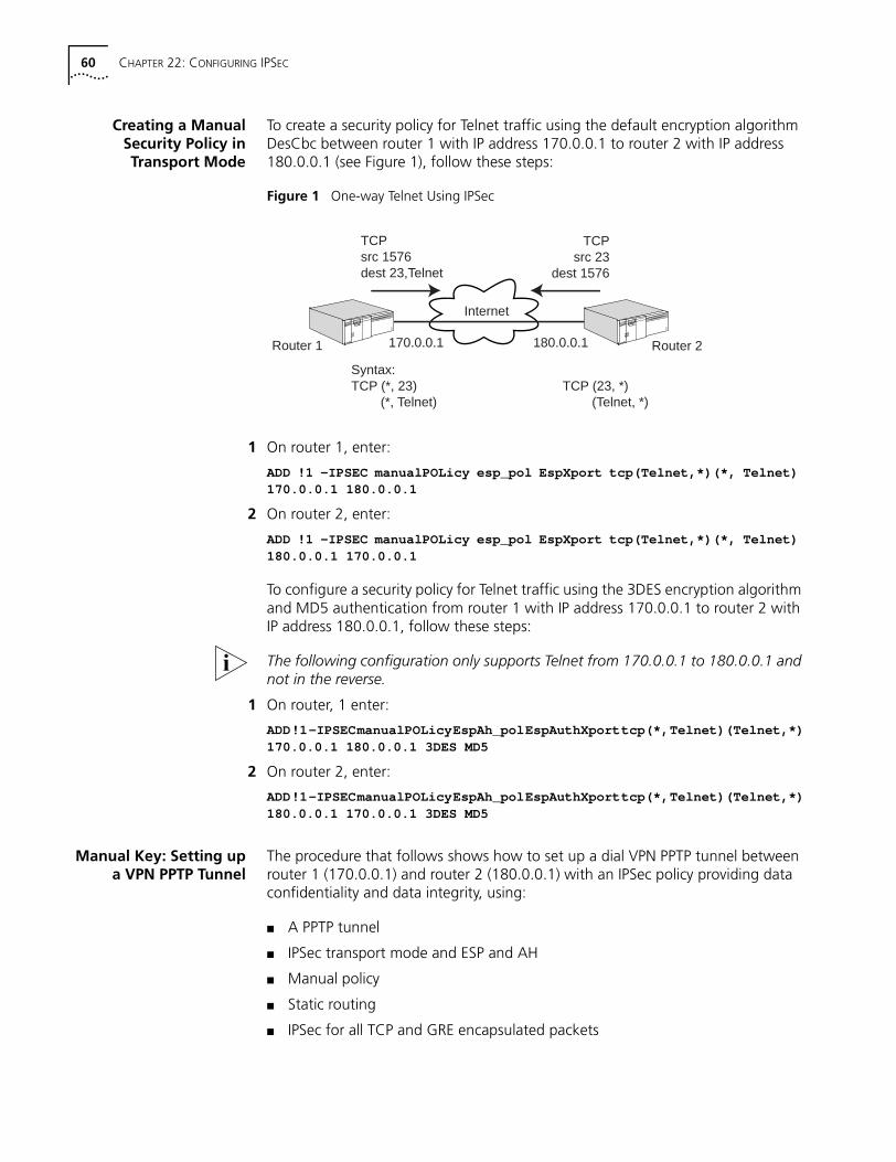
60 CHAPTER 22: CONFIGURING IPSEC
Creating a ManualSecurity Policy inTransport Mode
To create a security policy for Telnet traffic using the default encryption algorithm DesCbc between router 1 with IP address 170.0.0.1 to router 2 with IP address 180.0.0.1 (see Figure 1), follow these steps:
Figure 1 One-way Telnet Using IPSec
1 On router 1, enter:
ADD !1 -IPSEC manualPOLicy esp_pol EspXport tcp(Telnet,*)(*, Telnet)170.0.0.1 180.0.0.1
2 On router 2, enter:
ADD !1 -IPSEC manualPOLicy esp_pol EspXport tcp(Telnet,*)(*, Telnet)180.0.0.1 170.0.0.1
To configure a security policy for Telnet traffic using the 3DES encryption algorithm and MD5 authentication from router 1 with IP address 170.0.0.1 to router 2 with IP address 180.0.0.1, follow these steps:
The following configuration only supports Telnet from 170.0.0.1 to 180.0.0.1 and not in the reverse.
1 On router, 1 enter:
ADD!1-IPSECmanualPOLicyEspAh_polEspAuthXporttcp(*,Telnet)(Telnet,*)170.0.0.1 180.0.0.1 3DES MD5
2 On router 2, enter:
ADD!1-IPSECmanualPOLicyEspAh_polEspAuthXporttcp(*,Telnet)(Telnet,*)180.0.0.1 170.0.0.1 3DES MD5
Manual Key: Setting upa VPN PPTP Tunnel
The procedure that follows shows how to set up a dial VPN PPTP tunnel between router 1 (170.0.0.1) and router 2 (180.0.0.1) with an IPSec policy providing data confidentiality and data integrity, using:
■ A PPTP tunnel
■ IPSec transport mode and ESP and AH
■ Manual policy
■ Static routing
■ IPSec for all TCP and GRE encapsulated packets
Router 1 Router 2
Internet
Syntax:TCP (*, 23) TCP (23, *) (*, Telnet) (Telnet, *)
170.0.0.1 180.0.0.1
TCPsrc 1576dest 23,Telnet
TCPsrc 23
dest 1576
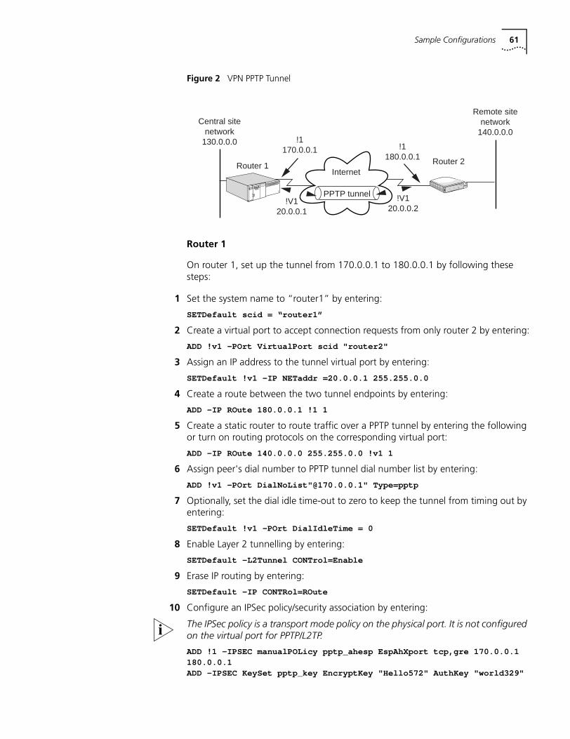
Sample Configurations 61
Figure 2 VPN PPTP Tunnel
Router 1
On router 1, set up the tunnel from 170.0.0.1 to 180.0.0.1 by following these steps:
1 Set the system name to “router1” by entering:
SETDefault scid = “router1”
2 Create a virtual port to accept connection requests from only router 2 by entering:
ADD !v1 -POrt VirtualPort scid "router2"
3 Assign an IP address to the tunnel virtual port by entering:
SETDefault !v1 -IP NETaddr =20.0.0.1 255.255.0.0
4 Create a route between the two tunnel endpoints by entering:
ADD -IP ROute 180.0.0.1 !1 1
5 Create a static router to route traffic over a PPTP tunnel by entering the following or turn on routing protocols on the corresponding virtual port:
ADD -IP ROute 140.0.0.0 255.255.0.0 !v1 1
6 Assign peer's dial number to PPTP tunnel dial number list by entering:
ADD !v1 -POrt DialNoList"@170.0.0.1" Type=pptp
7 Optionally, set the dial idle time-out to zero to keep the tunnel from timing out by entering:
SETDefault !v1 -POrt DialIdleTime = 0
8 Enable Layer 2 tunnelling by entering:
SETDefault -L2Tunnel CONTrol=Enable
9 Erase IP routing by entering:
SETDefault -IP CONTRol=ROute
10 Configure an IPSec policy/security association by entering:
The IPSec policy is a transport mode policy on the physical port. It is not configured on the virtual port for PPTP/L2TP.
ADD !1 -IPSEC manualPOLicy pptp_ahesp EspAhXport tcp,gre 170.0.0.1180.0.0.1ADD -IPSEC KeySet pptp_key EncryptKey "Hello572" AuthKey "world329"
Remote sitenetwork
140.0.0.0Central site
network130.0.0.0
Router 2Router 1
!1170.0.0.1 !1
180.0.0.1
!V120.0.0.2
!V120.0.0.1
Internet
PPTP tunnelNETBuilder
RouterCONNECTO F F I C E
System
WAN
ISDN
LAN
LineActLineError
Link
Connect
Fault
Send
Active
Fault
Line
Active
FaultRun
Load
Test
B1 B2
Status
Pwr Fwd
Alert
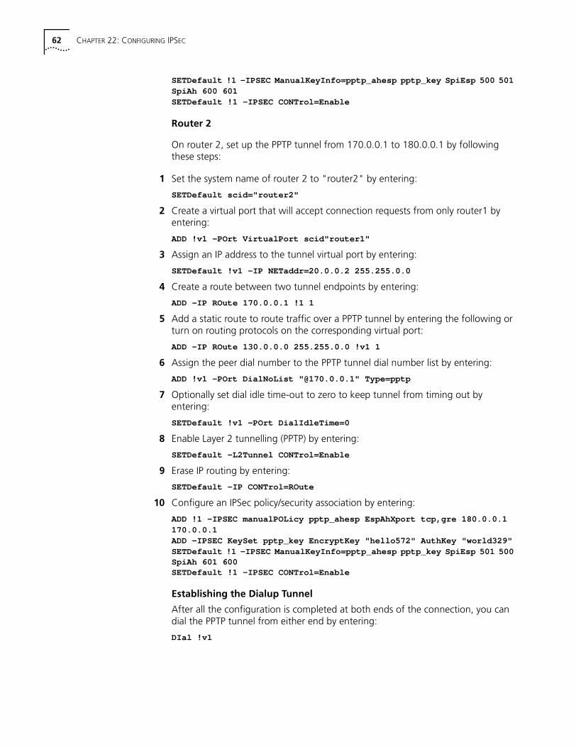
62 CHAPTER 22: CONFIGURING IPSEC
SETDefault !1 -IPSEC ManualKeyInfo=pptp_ahesp pptp_key SpiEsp 500 501SpiAh 600 601SETDefault !1 -IPSEC CONTrol=Enable
Router 2
On router 2, set up the PPTP tunnel from 170.0.0.1 to 180.0.0.1 by following these steps:
1 Set the system name of router 2 to "router2" by entering:
SETDefault scid="router2"
2 Create a virtual port that will accept connection requests from only router1 by entering:
ADD !v1 -POrt VirtualPort scid"router1"
3 Assign an IP address to the tunnel virtual port by entering:
SETDefault !v1 -IP NETaddr=20.0.0.2 255.255.0.0
4 Create a route between two tunnel endpoints by entering:
ADD -IP ROute 170.0.0.1 !1 1
5 Add a static route to route traffic over a PPTP tunnel by entering the following or turn on routing protocols on the corresponding virtual port:
ADD -IP ROute 130.0.0.0 255.255.0.0 !v1 1
6 Assign the peer dial number to the PPTP tunnel dial number list by entering:
ADD !v1 -POrt DialNoList "@170.0.0.1" Type=pptp
7 Optionally set dial idle time-out to zero to keep tunnel from timing out by entering:
SETDefault !v1 -POrt DialIdleTime=0
8 Enable Layer 2 tunnelling (PPTP) by entering:
SETDefault -L2Tunnel CONTrol=Enable
9 Erase IP routing by entering:
SETDefault -IP CONTrol=ROute
10 Configure an IPSec policy/security association by entering:
ADD !1 -IPSEC manualPOLicy pptp_ahesp EspAhXport tcp,gre 180.0.0.1170.0.0.1ADD -IPSEC KeySet pptp_key EncryptKey "hello572" AuthKey "world329"SETDefault !1 -IPSEC ManualKeyInfo=pptp_ahesp pptp_key SpiEsp 501 500SpiAh 601 600SETDefault !1 -IPSEC CONTrol=Enable
Establishing the Dialup Tunnel
After all the configuration is completed at both ends of the connection, you can dial the PPTP tunnel from either end by entering:
DIal !v1
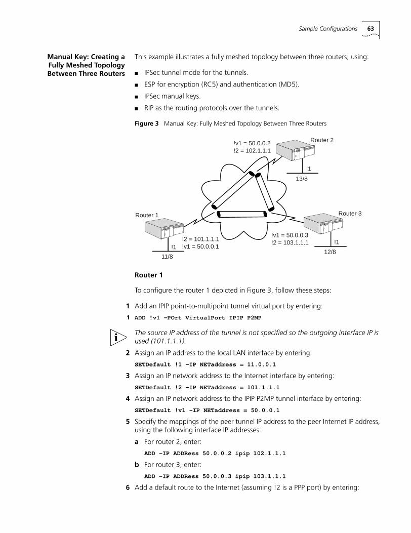
Sample Configurations 63
Manual Key: Creating aFully Meshed TopologyBetween Three Routers
This example illustrates a fully meshed topology between three routers, using:
■ IPSec tunnel mode for the tunnels.
■ ESP for encryption (RC5) and authentication (MD5).
■ IPSec manual keys.
■ RIP as the routing protocols over the tunnels.
Figure 3 Manual Key: Fully Meshed Topology Between Three Routers
Router 1
To configure the router 1 depicted in Figure 3, follow these steps:
1 Add an IPIP point-to-multipoint tunnel virtual port by entering:
1 ADD !v1 -POrt VirtualPort IPIP P2MP
The source IP address of the tunnel is not specified so the outgoing interface IP is used (101.1.1.1).
2 Assign an IP address to the local LAN interface by entering:
SETDefault !1 -IP NETaddress = 11.0.0.1
3 Assign an IP network address to the Internet interface by entering:
SETDefault !2 -IP NETaddress = 101.1.1.1
4 Assign an IP network address to the IPIP P2MP tunnel interface by entering:
SETDefault !v1 -IP NETaddress = 50.0.0.1
5 Specify the mappings of the peer tunnel IP address to the peer Internet IP address, using the following interface IP addresses:
a For router 2, enter:
ADD -IP ADDRess 50.0.0.2 ipip 102.1.1.1
b For router 3, enter:
ADD -IP ADDRess 50.0.0.3 ipip 103.1.1.1
6 Add a default route to the Internet (assuming !2 is a PPP port) by entering:
Router 1 Router 3
!2 = 101.1.1.1!v1 = 50.0.0.1
!v1 = 50.0.0.3!2 = 103.1.1.1
!1!1
Router 2
!1
!v1 = 50.0.0.2!2 = 102.1.1.1
13/8
12/811/8
64 CHAPTER 22: CONFIGURING IPSEC
ADD -IP ROute 0.0.0.0 !2 1
7 Enable IP routing by entering:
SETDefault -IP CoNTrol = ROute
8 Configure the IP security information.
a Configure an IPSec manual policy on the tunnel port (see How IPSec Works earlier in this chapter), by entering:
ADD !v1 -IPSEC manualPOLicy pol_eat eat default rc5 md5
This policy uses RC5 for encryption and MD5 for authentication All traffic over the virtual port (default) will match this policy.
b Configure the encryption and authentication keys (see “Configuring Dynamic-Key Security Policies” earlier in this chapter) by entering:
ADD -IPSEC KeySet ks_ea ek "ek12345678" ak "ak12345678"
c Bind the keys to the policies and configure the SPIs (see Creating Manual Policies earlier in this chapter) by entering:
SETDefault !v1 -IPSEC ManualKeyInfo pol_eat 102.1.1.1 ks_ea se 500 501SETDefault !v1 -IPSEC ManualKeyInfo pol_eat 103.1.1.1 ks_ea se 500 501
Since ESP is not used for authentication , a Spi_ah value is not needed.
9 Enable IPSec control on the tunnel port by entering:
SETDefault !v1 -IPSEC CONTrol = e
10 Check the configuration, by entering:
SHow -IPSEC CONFiguration
11 Enable RIP Talk and Listen on the tunnel port by entering:
SETDefault !v1 -RIP CONTrol= (ta, li)
Router 2
To configure the router 2 depicted in Figure 3, perform the steps in “Router 1” entering the following information:
ADD !v1 -POrt VirtualPort IPIP P2MPSETDefault !1 -IP NETaddress = 12.0.0.1SETDefault !2 -IP NETaddress = 102.1.1.1SETDefault !v1 -IP NETaddress = 50.0.0.2ADD -IP ADDRess 50.0.0.1 IPIP 101.1.1.1ADD -IP ADDRess 50.0.0.3 IPIP 103.1.1.1ADD -IP ROute 0.0.0.0 !2 1SETDefault -IP CONTrol = ROuteADD !v1 -IPSEC manualPOLicy pol_eat eat default rc5 md5ADD -IPSEC KeySet ks_ea ek "ek12345678" ak "ak12345678"SETDefault !v1 -IPSEC ManualKeyInfo = pol_eat 101.1.1.1 ks_ea se 501 500SETDefault !v1 -IPSEC ManualKeyInfo = pol_eat 103.1.1.1 ks_ea se 600 601SETDefault !v1 -IPSEC CONTrol = eSETDefault !v1 -RIP CONTrol = (ta, li)
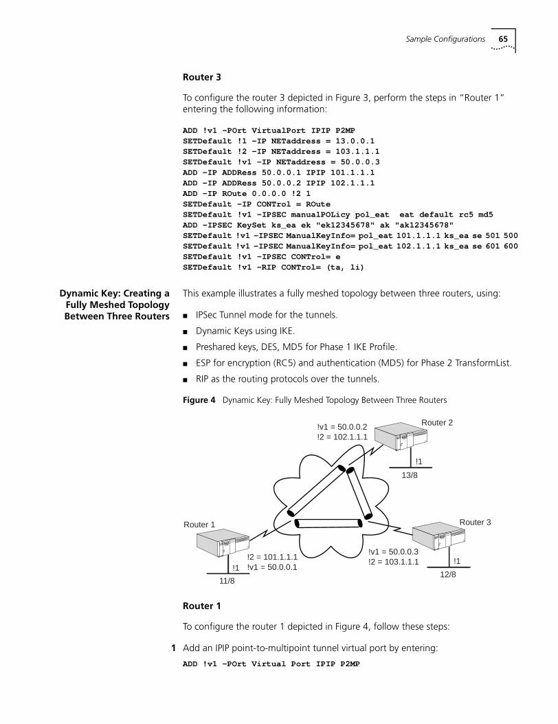
Sample Configurations 65
Router 3
To configure the router 3 depicted in Figure 3, perform the steps in “Router 1” entering the following information:
ADD !v1 -POrt VirtualPort IPIP P2MPSETDefault !1 -IP NETaddress = 13.0.0.1SETDefault !2 -IP NETaddress = 103.1.1.1SETDefault !v1 -IP NETaddress = 50.0.0.3ADD -IP ADDRess 50.0.0.1 IPIP 101.1.1.1ADD -IP ADDRess 50.0.0.2 IPIP 102.1.1.1ADD -IP ROute 0.0.0.0 !2 1SETDefault -IP CONTrol = ROuteSETDefault !v1 -IPSEC manualPOLicy pol_eat eat default rc5 md5ADD -IPSEC KeySet ks_ea ek "ek12345678" ak "ak12345678"SETDefault !v1 -IPSEC ManualKeyInfo= pol_eat 101.1.1.1 ks_ea se 501 500SETDefault !v1 -IPSEC ManualKeyInfo= pol_eat 102.1.1.1 ks_ea se 601 600SETDefault !v1 -IPSEC CONTrol= eSETDefault !v1 -RIP CONTrol= (ta, li)
Dynamic Key: Creating aFully Meshed TopologyBetween Three Routers
This example illustrates a fully meshed topology between three routers, using:
■ IPSec Tunnel mode for the tunnels.
■ Dynamic Keys using IKE.
■ Preshared keys, DES, MD5 for Phase 1 IKE Profile.
■ ESP for encryption (RC5) and authentication (MD5) for Phase 2 TransformList.
■ RIP as the routing protocols over the tunnels.
Figure 4 Dynamic Key: Fully Meshed Topology Between Three Routers
Router 1
To configure the router 1 depicted in Figure 4, follow these steps:
1 Add an IPIP point-to-multipoint tunnel virtual port by entering:
ADD !v1 -POrt Virtual Port IPIP P2MP
Router 1 Router 3
!2 = 101.1.1.1!v1 = 50.0.0.1
!v1 = 50.0.0.3!2 = 103.1.1.1
!1!1
Router 2
!1
!v1 = 50.0.0.2!2 = 102.1.1.1
13/8
12/811/8
66 CHAPTER 22: CONFIGURING IPSEC
2 Assign an IP address to the local LAN interface by entering:
SETDefault !1 -IP NETaddress = 11.0.0.1
3 Assign an IP network address to the Internet interface by entering:
SETDefault !2 -IP NETaddress = 101.1.1.1
4 Assign an IP network address to the IPIP P2MP tunnel interface by entering:
SETDefault !v1 -IP NETaddress = 50.0.0.1
5 Specify the mappings of the peer Tunnel IP address to the peer Internet interface IP addresses using the following interface IP addresses:
a For router 2, enter:
ADD -IP ADDRess 50.0.0.2 ipip 102.1.1.1
b For router 3, enter:
ADD -IP ADDRess 50.0.0.3 ipip 103.1.1.1
6 Add a default route to the Internet (assuming !2 is a PPP port) by entering:
ADD -IP ROute 0.0.0.0 !2 1
7 Enable IP routing by entering:
SETDefault -IP CONTrol = ROute
8 Configure the IP security information.
a Add a selector list to choose which Traffic the policies will apply to. In this case, all traffic over the tunnel is to be encrypted, so the values of 0.0.0.0/0 are used. Enter:
ADD -IPSEC SelectorLIst sl10 10 include any 0.0.0.0/0 0.0.0.0/0
b Add a transform list that specifies the Phase 2 SA. (This is the description of the security for the actual data packets over the tunnel.) Enter:
ADD TransformLIst tl10 10 ESP-RC5 ESP-MD5
c Define a common preshared key shared by all routers that need to communicate with each other. In this case, mask 0.0.0.0/0 is used to select all routers. Enter:
ADD PreSharedKey 0.0.0.0/0 "secretkey"
d Define an IKE profile that describes the Phase 1 SA. This is used by IKE to secure its own negotiation, and is not used to secure the data traffic. Enter:
ADD IKEProfile 10 PreSharedKey des md5
e Bind all the information together using a DynamicPOLicy by entering:
ADD !v1 DynamicPOLicy pol_ea10 10 Tunnel sl10 tl10
f Enable IPSec Control on the tunnel port by entering:
SETDefault !v1 -IPSEC CONTrol = e
g Check the IPSec configuration by entering:
SHow -IPSEC CONFiguration
9 Enable RIP Talk and Listen on the tunnel port by entering:
SETDefault !v1 -RIP CONTrol= (ta, li)
Sample Configurations 67
Router 2
To configure the router 2 depicted in Figure 4, follow steps 1 through 10 in “Router 1” entering the following information:
ADD !v1 -POrt VirtualPort IPIP P2MPSETDefault !1 -IP NETaddress = 12.0.0.1SETDefault !2 -IP NETaddress = 102.1.1.1SETDefault !v1 -IP NETaddress = 50.0.0.2ADD -IP ADDRess 50.0.0.1 IPIP 101.1.1.1ADD -IP ADDRess 50.0.0.3 IPIP 103.1.1.1ADD -IP ROute 0.0.0.0 !2 1SETDefault -IP CONtrol = ROute
10 Configure the IP Security information.
a Add a SelectorList to choose which Traffic the policies will apply to. In this case all traffic over the Tunnel is to be encrypted, so the values 0.0.0.0/ are used. Enter:
ADD -IPSEC SelectorLIst sl10 10 include any 0.0.0.0/0 0.0.0.0/0
b Add a transform list that specifies the Phase 2 SA. This is the description of the security for the actual data packets over the tunnel. Enter:
ADD TransformLIst tl10 10 ESP-RC5 ESP-MD5
c Define a common preshared key shared by all routers that need to communicate. In this case, the mask 0.0.0.0/0 is used to select all routers. Enter:
ADD PreSharedKey 0.0.0.0/0 "secretkey"
d Define an IKE profile that describes the Phase 1 SA. This is used by IKE to secure its own negotiation and is not used to secure the data traffic. Enter:
ADD IKEProfile 10 PreSharedKey des md5
e Bind all the information together using a DynamicPOLicy by entering:
ADD !v1 DynamicPOLicy pol_ea10 10 Tunnel sl10 tl10
f Enable IPSec Control on the Tunnel port by entering:
SETDefault !v1 -IPSEC CONTrol = e
g Check the IPSec configuration by entering:
SHow -IPSEC CONFigurationSETDefault !v1 -RIP CONTrol= (ta, li)
Router 3
To configure the router 3 depicted in Figure 4, follow steps 1 through 10 in “Router 1” entering the following information:
ADD !v1 -POrt VirtualPort IPIP P2MPSETDefault !1 -IP NETaddress = 13.0.0.1SETDefault !2 -IP NETaddress = 103.1.1.1SETDefault !v1 -IP NETaddress = 50.0.0.3ADD -IP ADDRess 50.0.0.1 IPIP 101.1.1.1ADD -IP ADDRess 50.0.0.2 IPIP 102.1.1.1ADD -IP ROute 0.0.0.0 !2 1SETDefault -IP CONTrol = ROute
68 CHAPTER 22: CONFIGURING IPSEC
11 Configure the IP security information.
a Add a SelectorList to choose which Traffic the policies will apply to. In this case all traffic over the Tunnel is to be encrypted, so the values 0.0.0.0/ are used. Enter:
ADD -IPSEC SelectorLIst sl10 10 include any 0.0.0.0/0 0.0.0.0/0
b Add a transform list that specifies the Phase 2 SA. This is the description of the security for the actual data packets over the tunnel. Enter:
ADD TransformLIst tl10 10 ESP-RC5 ESP-MD5
c Define a common preshared key shared by all routers that need to communicate. In this case, the mask 0.0.0.0/0 is used to select all routers. Enter:
ADD PreSharedKey 0.0.0.0/0 "secretkey"
d Define an IKE profile that describes the Phase 1 SA. This is used by IKE to secure its own negotiation and is not used to secure the data traffic. Enter:
ADD IKEProfile 10 PreSharedKey des md5
e Bind all the information together using a DynamicPOLicy by entering:
ADD !v1 DynamicPOLicy pol_ea10 10 Tunnel sl10 tl10
f Enable IPSec Control on the Tunnel port by entering:
SETDefault !v1 -IPSEC CONTrol = e
g Check the IPSec configuration by entering:
SHow -IPSEC confSETDefault !v1 -RIP CONTrol = (ta, li)
Dynamic Key: Hub andSpoke Topology
Between Three Routers
This example illustrates a hub and spoke topology between three routers, using:
■ L2TP or PPTP for tunnels.
■ IPSec Transport mode.
■ Dynamic Keys using IKE.
■ Phase 1 IKE Profile using preshared keys, DES, MD5.
■ Phase 2 TransformList using ESP for encryption (RC5).
■ OSPF as the routing protocols over the tunnels.
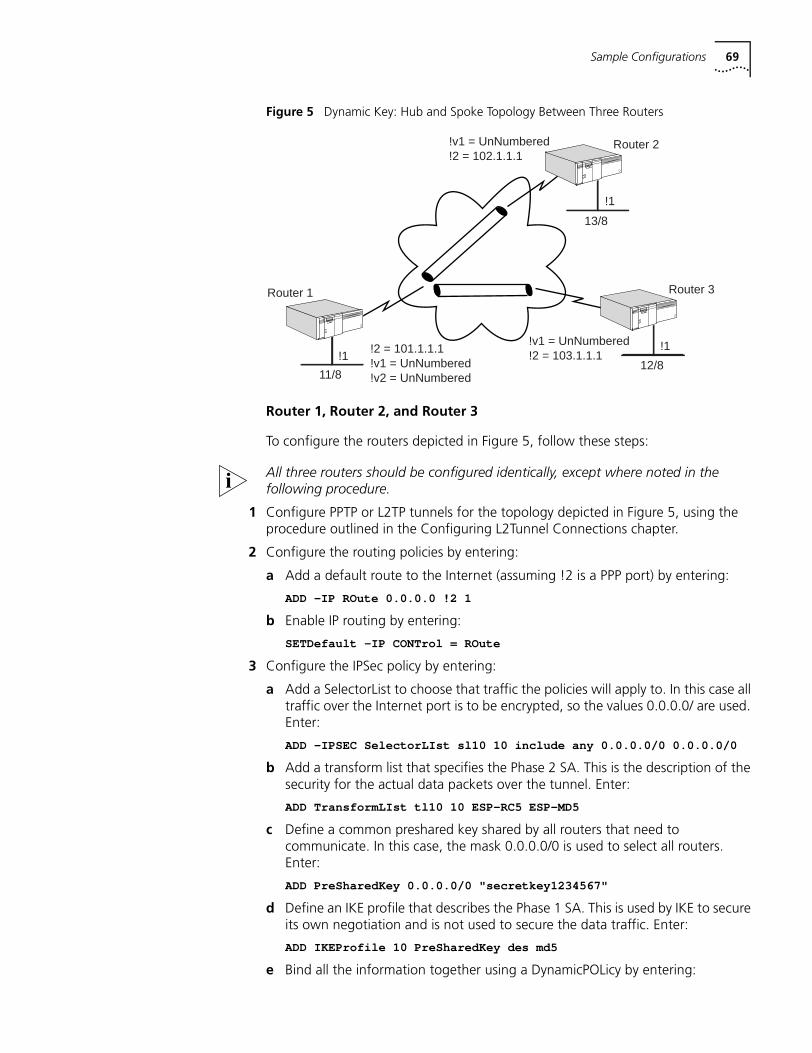
Sample Configurations 69
Figure 5 Dynamic Key: Hub and Spoke Topology Between Three Routers
Router 1, Router 2, and Router 3
To configure the routers depicted in Figure 5, follow these steps:
All three routers should be configured identically, except where noted in the following procedure.
1 Configure PPTP or L2TP tunnels for the topology depicted in Figure 5, using the procedure outlined in the Configuring L2Tunnel Connections chapter.
2 Configure the routing policies by entering:
a Add a default route to the Internet (assuming !2 is a PPP port) by entering:
ADD -IP ROute 0.0.0.0 !2 1
b Enable IP routing by entering:
SETDefault -IP CONTrol = ROute
3 Configure the IPSec policy by entering:
a Add a SelectorList to choose that traffic the policies will apply to. In this case all traffic over the Internet port is to be encrypted, so the values 0.0.0.0/ are used. Enter:
ADD -IPSEC SelectorLIst sl10 10 include any 0.0.0.0/0 0.0.0.0/0
b Add a transform list that specifies the Phase 2 SA. This is the description of the security for the actual data packets over the tunnel. Enter:
ADD TransformLIst tl10 10 ESP-RC5 ESP-MD5
c Define a common preshared key shared by all routers that need to communicate. In this case, the mask 0.0.0.0/0 is used to select all routers. Enter:
ADD PreSharedKey 0.0.0.0/0 "secretkey1234567"
d Define an IKE profile that describes the Phase 1 SA. This is used by IKE to secure its own negotiation and is not used to secure the data traffic. Enter:
ADD IKEProfile 10 PreSharedKey des md5
e Bind all the information together using a DynamicPOLicy by entering:
Router 1 Router 3
!2 = 101.1.1.1!v1 = UnNumbered!v2 = UnNumbered
!v1 = UnNumbered!2 = 103.1.1.1!1
!1
Router 2
!1
!v1 = UnNumbered!2 = 102.1.1.1
13/8
12/811/8
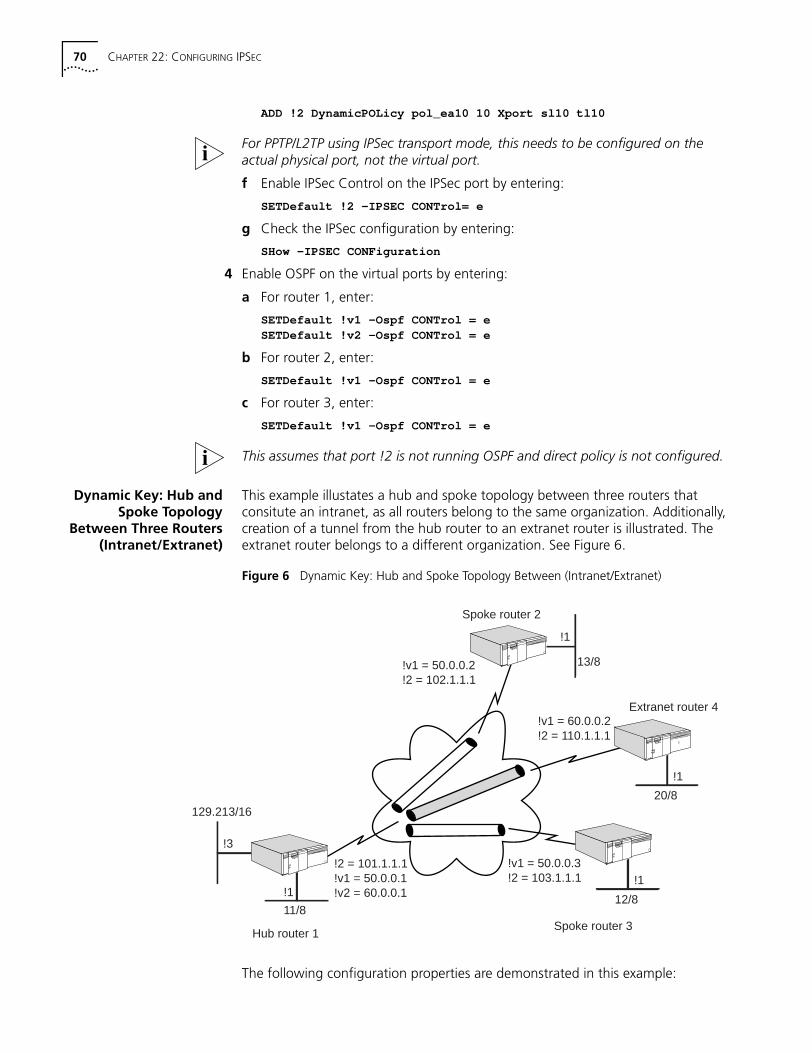
70 CHAPTER 22: CONFIGURING IPSEC
ADD !2 DynamicPOLicy pol_ea10 10 Xport sl10 tl10
For PPTP/L2TP using IPSec transport mode, this needs to be configured on the actual physical port, not the virtual port.
f Enable IPSec Control on the IPSec port by entering:
SETDefault !2 -IPSEC CONTrol= e
g Check the IPSec configuration by entering:
SHow -IPSEC CONFiguration
4 Enable OSPF on the virtual ports by entering:
a For router 1, enter:
SETDefault !v1 -Ospf CONTrol = eSETDefault !v2 -Ospf CONTrol = e
b For router 2, enter:
SETDefault !v1 -Ospf CONTrol = e
c For router 3, enter:
SETDefault !v1 -Ospf CONTrol = e
This assumes that port !2 is not running OSPF and direct policy is not configured.
Dynamic Key: Hub andSpoke Topology
Between Three Routers(Intranet/Extranet)
This example illustates a hub and spoke topology between three routers that consitute an intranet, as all routers belong to the same organization. Additionally, creation of a tunnel from the hub router to an extranet router is illustrated. The extranet router belongs to a different organization. See Figure 6.
Figure 6 Dynamic Key: Hub and Spoke Topology Between (Intranet/Extranet)
The following configuration properties are demonstrated in this example:
Hub router 1Spoke router 3
!2 = 101.1.1.1!v1 = 50.0.0.1!v2 = 60.0.0.1
!v1 = 50.0.0.3!2 = 103.1.1.1
Spoke router 2
!v1 = 50.0.0.2!2 = 102.1.1.1
13/8
12/811/8
129.213/1620/8
Extranet router 4!v1 = 60.0.0.2!2 = 110.1.1.1
!3
!1
!1
!1
!1
Sample Configurations 71
■ The hub router has an IPIP P2MP tunnel connected to its Intranet spoke routers.
■ The intranet spoke routers have a P2P tunnel connected to the hub.
■ The hub router has a P2P tunnel over a separate virtual port to the extranet router. (It is best to use a separate virtual port for the extranet router as this makes configuring policies simpler, and there is less chance of creating a security hole.)
■ IPSec Tunnel mode is used with IKE.
■ Hub to intranet routers: IPSec on all OSPF traffic.
■ Hub to extranet: IPSec on all data and RIP traffic.
■ Hub to intranet router R2: ESP-3DES ESP-MD5.
■ Hub to intranet router R3: ESP-DES ESP-MD5.
■ An IPSec GlobalLifeTime of 30-minutes is used.
■ With the intranet routers, the IKEProfiles have a lifetime of 6-hours and Group1 PFS.
■ Hub to extranet router R4: ESP-RC5 and ESP-SHA.
■ With the extranet router, the IKEProfile uses 3DES, MD5, Group2 PFS.
■ OSPF is used for routing over the intranet.
■ RIPv2 is used for routing to the extranet router.
■ There should be complete connectivity in the intranet.
■ The extranet router should only see network 129.213/16.
Spoke Router 1
To configure the spoke router 1 depicted in Figure 6, follow these steps:
1 Configure the system prompt by entering:
SETDefault -SYS NMPrompt = "HubRtr1 # "
2 Assign an IP address to the local LAN interface by entering:
SETDefault !1 -IP NETaddr = 11.0.0.1
3 Assign an IP address to the Internet interface by entering:
SETDefault !2 -IP NETaddr = 101.1.1.1
4 Assign an IP address to interface that is exposed to extranet by entering:
SETDefault !3 -IP NETaddr = 129.213.1.1
5 Add an IPIP point-to-multipoint virtual port for the intranet by entering:
ADD !v1 -PORT VirtualPort IPIP P2MPSETDefault !v1 -IP NETaddr = 50.0.0.1
6 Add an IPIP point-to-Point virtual port for the extranet router by entering:
ADD !v2 -PORT virtualPort ipip 110.1.1.1SETDefault !v2 -IP NETaddr = 60.0.0.1
7 Specify the mappings of the peer tunnel IP address to the peer internet interface IP addresses for the intranet routers by entering:
ADD -IP ADDRess 50.0.0.2 IPIP 102.1.1.1ADD -IP ADDRess 50.0.0.3 IPIP 103.1.1.1
8 Add a default route to the internet (assuming !2 is a PPP port) by entering:
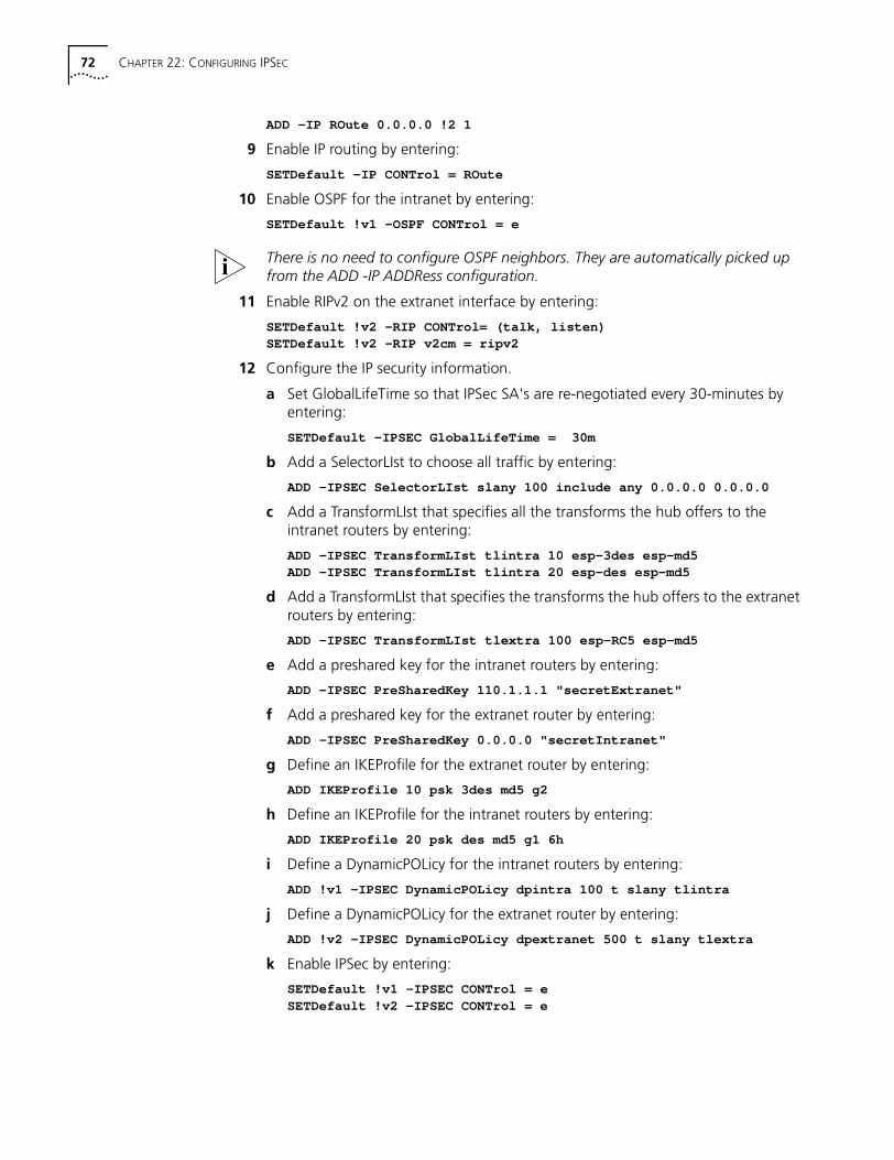
72 CHAPTER 22: CONFIGURING IPSEC
ADD -IP ROute 0.0.0.0 !2 1
9 Enable IP routing by entering:
SETDefault -IP CONTrol = ROute
10 Enable OSPF for the intranet by entering:
SETDefault !v1 -OSPF CONTrol = e
There is no need to configure OSPF neighbors. They are automatically picked up from the ADD -IP ADDRess configuration.
11 Enable RIPv2 on the extranet interface by entering:
SETDefault !v2 -RIP CONTrol= (talk, listen)SETDefault !v2 -RIP v2cm = ripv2
12 Configure the IP security information.
a Set GlobalLifeTime so that IPSec SA's are re-negotiated every 30-minutes by entering:
SETDefault -IPSEC GlobalLifeTime = 30m
b Add a SelectorLIst to choose all traffic by entering:
ADD -IPSEC SelectorLIst slany 100 include any 0.0.0.0 0.0.0.0
c Add a TransformLIst that specifies all the transforms the hub offers to the intranet routers by entering:
ADD -IPSEC TransformLIst tlintra 10 esp-3des esp-md5ADD -IPSEC TransformLIst tlintra 20 esp-des esp-md5
d Add a TransformLIst that specifies the transforms the hub offers to the extranet routers by entering:
ADD -IPSEC TransformLIst tlextra 100 esp-RC5 esp-md5
e Add a preshared key for the intranet routers by entering:
ADD -IPSEC PreSharedKey 110.1.1.1 "secretExtranet"
f Add a preshared key for the extranet router by entering:
ADD -IPSEC PreSharedKey 0.0.0.0 "secretIntranet"
g Define an IKEProfile for the extranet router by entering:
ADD IKEProfile 10 psk 3des md5 g2
h Define an IKEProfile for the intranet routers by entering:
ADD IKEProfile 20 psk des md5 g1 6h
i Define a DynamicPOLicy for the intranet routers by entering:
ADD !v1 -IPSEC DynamicPOLicy dpintra 100 t slany tlintra
j Define a DynamicPOLicy for the extranet router by entering:
ADD !v2 -IPSEC DynamicPOLicy dpextranet 500 t slany tlextra
k Enable IPSec by entering:
SETDefault !v1 -IPSEC CONTrol = eSETDefault !v2 -IPSEC CONTrol = e
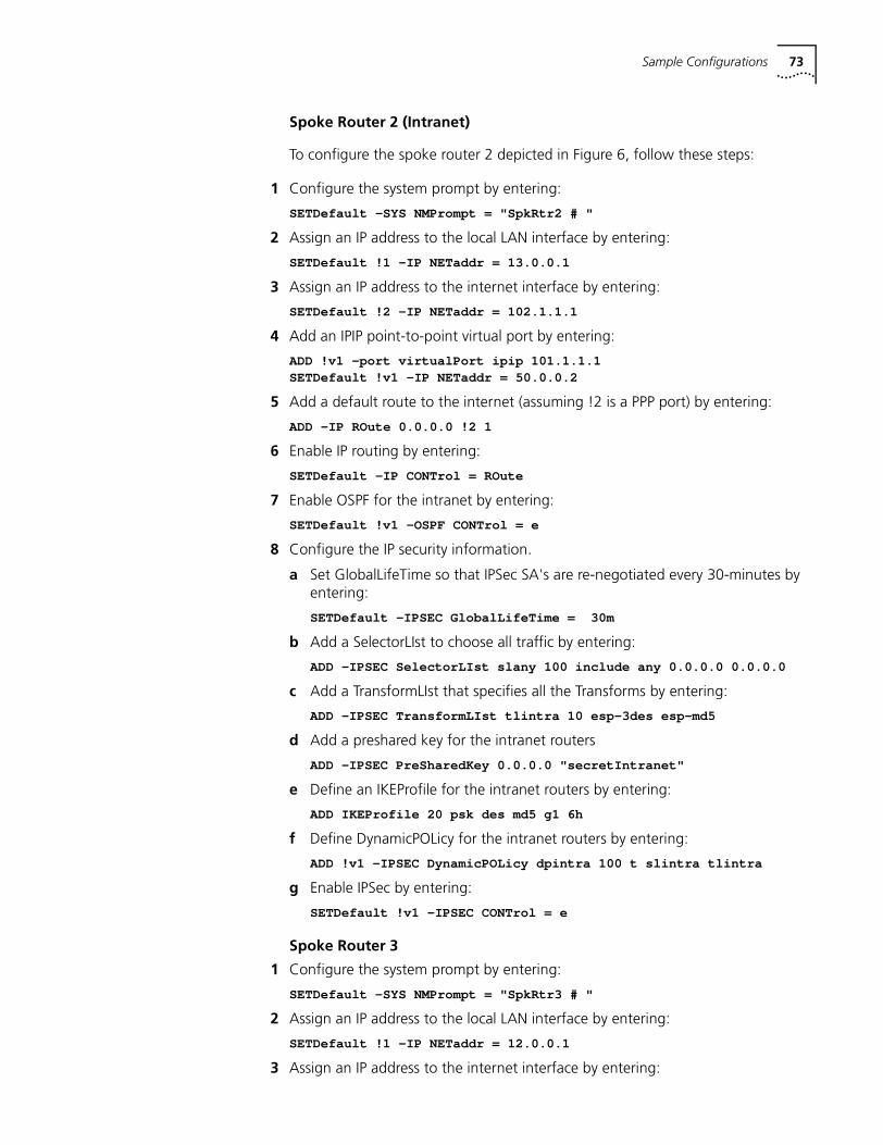
Sample Configurations 73
Spoke Router 2 (Intranet)
To configure the spoke router 2 depicted in Figure 6, follow these steps:
1 Configure the system prompt by entering:
SETDefault -SYS NMPrompt = "SpkRtr2 # "
2 Assign an IP address to the local LAN interface by entering:
SETDefault !1 -IP NETaddr = 13.0.0.1
3 Assign an IP address to the internet interface by entering:
SETDefault !2 -IP NETaddr = 102.1.1.1
4 Add an IPIP point-to-point virtual port by entering:
ADD !v1 -port virtualPort ipip 101.1.1.1SETDefault !v1 -IP NETaddr = 50.0.0.2
5 Add a default route to the internet (assuming !2 is a PPP port) by entering:
ADD -IP ROute 0.0.0.0 !2 1
6 Enable IP routing by entering:
SETDefault -IP CONTrol = ROute
7 Enable OSPF for the intranet by entering:
SETDefault !v1 -OSPF CONTrol = e
8 Configure the IP security information.
a Set GlobalLifeTime so that IPSec SA's are re-negotiated every 30-minutes by entering:
SETDefault -IPSEC GlobalLifeTime = 30m
b Add a SelectorLIst to choose all traffic by entering:
ADD -IPSEC SelectorLIst slany 100 include any 0.0.0.0 0.0.0.0
c Add a TransformLIst that specifies all the Transforms by entering:
ADD -IPSEC TransformLIst tlintra 10 esp-3des esp-md5
d Add a preshared key for the intranet routers
ADD -IPSEC PreSharedKey 0.0.0.0 "secretIntranet"
e Define an IKEProfile for the intranet routers by entering:
ADD IKEProfile 20 psk des md5 g1 6h
f Define DynamicPOLicy for the intranet routers by entering:
ADD !v1 -IPSEC DynamicPOLicy dpintra 100 t slintra tlintra
g Enable IPSec by entering:
SETDefault !v1 -IPSEC CONTrol = e
Spoke Router 3
1 Configure the system prompt by entering:
SETDefault -SYS NMPrompt = "SpkRtr3 # "
2 Assign an IP address to the local LAN interface by entering:
SETDefault !1 -IP NETaddr = 12.0.0.1
3 Assign an IP address to the internet interface by entering:
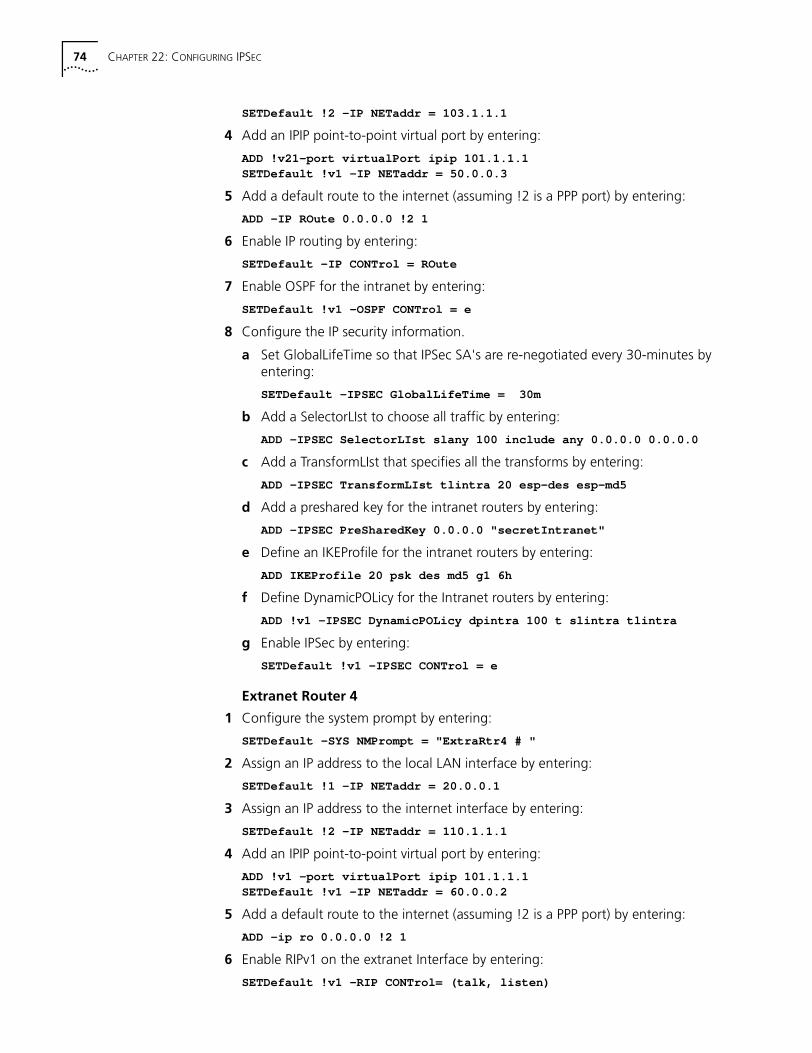
74 CHAPTER 22: CONFIGURING IPSEC
SETDefault !2 -IP NETaddr = 103.1.1.1
4 Add an IPIP point-to-point virtual port by entering:
ADD !v21-port virtualPort ipip 101.1.1.1SETDefault !v1 -IP NETaddr = 50.0.0.3
5 Add a default route to the internet (assuming !2 is a PPP port) by entering:
ADD -IP ROute 0.0.0.0 !2 1
6 Enable IP routing by entering:
SETDefault -IP CONTrol = ROute
7 Enable OSPF for the intranet by entering:
SETDefault !v1 -OSPF CONTrol = e
8 Configure the IP security information.
a Set GlobalLifeTime so that IPSec SA's are re-negotiated every 30-minutes by entering:
SETDefault -IPSEC GlobalLifeTime = 30m
b Add a SelectorLIst to choose all traffic by entering:
ADD -IPSEC SelectorLIst slany 100 include any 0.0.0.0 0.0.0.0
c Add a TransformLIst that specifies all the transforms by entering:
ADD -IPSEC TransformLIst tlintra 20 esp-des esp-md5
d Add a preshared key for the intranet routers by entering:
ADD -IPSEC PreSharedKey 0.0.0.0 "secretIntranet"
e Define an IKEProfile for the intranet routers by entering:
ADD IKEProfile 20 psk des md5 g1 6h
f Define DynamicPOLicy for the Intranet routers by entering:
ADD !v1 -IPSEC DynamicPOLicy dpintra 100 t slintra tlintra
g Enable IPSec by entering:
SETDefault !v1 -IPSEC CONTrol = e
Extranet Router 4
1 Configure the system prompt by entering:
SETDefault -SYS NMPrompt = "ExtraRtr4 # "
2 Assign an IP address to the local LAN interface by entering:
SETDefault !1 -IP NETaddr = 20.0.0.1
3 Assign an IP address to the internet interface by entering:
SETDefault !2 -IP NETaddr = 110.1.1.1
4 Add an IPIP point-to-point virtual port by entering:
ADD !v1 -port virtualPort ipip 101.1.1.1SETDefault !v1 -IP NETaddr = 60.0.0.2
5 Add a default route to the internet (assuming !2 is a PPP port) by entering:
ADD -ip ro 0.0.0.0 !2 1
6 Enable RIPv1 on the extranet Interface by entering:
SETDefault !v1 -RIP CONTrol= (talk, listen)
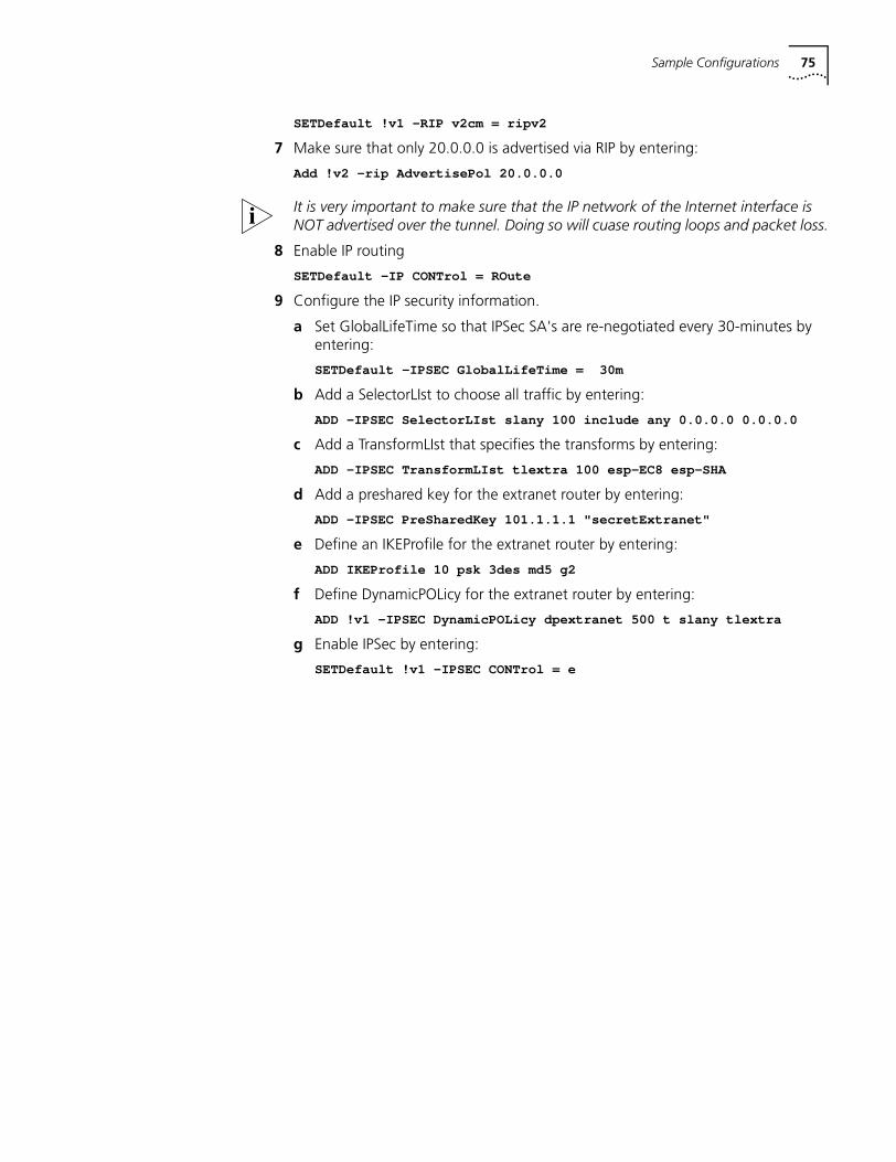
Sample Configurations 75
SETDefault !v1 -RIP v2cm = ripv2
7 Make sure that only 20.0.0.0 is advertised via RIP by entering:
Add !v2 -rip AdvertisePol 20.0.0.0
It is very important to make sure that the IP network of the Internet interface is NOT advertised over the tunnel. Doing so will cuase routing loops and packet loss.
8 Enable IP routing
SETDefault -IP CONTrol = ROute
9 Configure the IP security information.
a Set GlobalLifeTime so that IPSec SA's are re-negotiated every 30-minutes by entering:
SETDefault -IPSEC GlobalLifeTime = 30m
b Add a SelectorLIst to choose all traffic by entering:
ADD -IPSEC SelectorLIst slany 100 include any 0.0.0.0 0.0.0.0
c Add a TransformLIst that specifies the transforms by entering:
ADD -IPSEC TransformLIst tlextra 100 esp-EC8 esp-SHA
d Add a preshared key for the extranet router by entering:
ADD -IPSEC PreSharedKey 101.1.1.1 "secretExtranet"
e Define an IKEProfile for the extranet router by entering:
ADD IKEProfile 10 psk 3des md5 g2
f Define DynamicPOLicy for the extranet router by entering:
ADD !v1 -IPSEC DynamicPOLicy dpextranet 500 t slany tlextra
g Enable IPSec by entering:
SETDefault !v1 -IPSEC CONTrol = e

76 CHAPTER 22: CONFIGURING IPSEC
9
CONFIGURING RSVPReplace the existing Configuring RSVP chapter in Using Enterprise OS Software with this updated chapter.
This chapter describes the Resource Reservation Protocol (RSVP), which is used by multicast applications like video conferencing, multimedia, and virtual private network (VPN) network management. RSVP permits applications to request Quality of Service assurances from the network.
What Is RSVP? RSVP provides the ability to reserve resources for consistent data delivery for applications that need it. Data applications need a relatively small amount of bandwidth, but multimedia applications demand high bandwidth. With both types of applications using the same network, RSVP allows the multimedia applications to reserve the bandwidth they need to successfully complete their transmission.
RSVP provides network consistency for realtime traffic. Without this network consistency, real time traffic can experience information loss, jitter, loss of synchronization, and not enough bandwidth.
There are three RSVP participants: the sender, the network, and the receiver. There can be multiple senders and receivers. Each sender application periodically sends an RSVP Path message to a receiver for each data flow it originates. One piece of information provided in the Path message is the characteristics of the data traffic the application expects to generate. These characteristics are the data rate (bandwidth), the queue size, and the maximum packet size (MTU).
The Path message travels from a sender to receiver(s) along the same route(s) used by data packets. A bridge/router in the network that does not implement RSVP, routes the Path message through as if it were a data packet. An RSVP-capable bridge/router, processes the information in the Path message and uses it later in the reservation request message(s) sent back in the reverse direction to the sender.
The receiver application initiates reservation requests based on information it receives from the Path message. Each bridge/router that receives a reservation request message (Resv) reserves the requested bandwidth, if there is sufficient bandwidth, and sends the Resv message to its previous hop which is the next bridge/router in the route toward the sender. If there is not sufficient bandwidth, the Resv message goes no further and an error message is sent back to the receiver application. One other requirement for a successful reservation request is that, on a per flow basis, bandwidth greater than the user-configurable MaxFlowRate parameter cannot be requested.
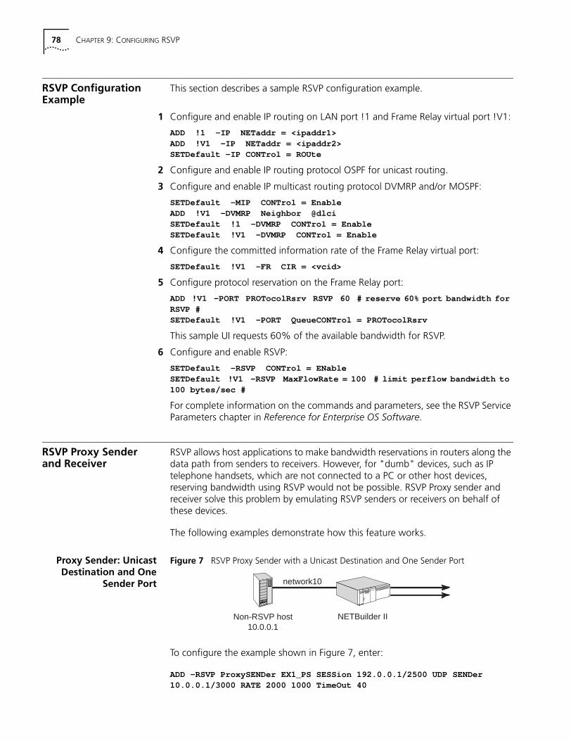
78 CHAPTER 9: CONFIGURING RSVP
RSVP Configuration Example
This section describes a sample RSVP configuration example.
1 Configure and enable IP routing on LAN port !1 and Frame Relay virtual port !V1:
ADD !1 -IP NETaddr = <ipaddr1>ADD !V1 -IP NETaddr = <ipaddr2>SETDefault -IP CONTrol = ROUte
2 Configure and enable IP routing protocol OSPF for unicast routing.
3 Configure and enable IP multicast routing protocol DVMRP and/or MOSPF:
SETDefault -MIP CONTrol = EnableADD !V1 -DVMRP Neighbor @dlciSETDefault !1 -DVMRP CONTrol = EnableSETDefault !V1 -DVMRP CONTrol = Enable
4 Configure the committed information rate of the Frame Relay virtual port:
SETDefault !V1 -FR CIR = <vcid>
5 Configure protocol reservation on the Frame Relay port:
ADD !V1 -PORT PROTocolRsrv RSVP 60 # reserve 60% port bandwidth forRSVP #SETDefault !V1 -PORT QueueCONTrol = PROTocolRsrv
This sample UI requests 60% of the available bandwidth for RSVP.
6 Configure and enable RSVP:
SETDefault -RSVP CONTrol = ENableSETDefault !V1 -RSVP MaxFlowRate = 100 # limit perflow bandwidth to100 bytes/sec #
For complete information on the commands and parameters, see the RSVP Service Parameters chapter in Reference for Enterprise OS Software.
RSVP Proxy Sender and Receiver
RSVP allows host applications to make bandwidth reservations in routers along the data path from senders to receivers. However, for "dumb" devices, such as IP telephone handsets, which are not connected to a PC or other host devices, reserving bandwidth using RSVP would not be possible. RSVP Proxy sender and receiver solve this problem by emulating RSVP senders or receivers on behalf of these devices.
The following examples demonstrate how this feature works.
Proxy Sender: UnicastDestination and One
Sender Port
Figure 7 RSVP Proxy Sender with a Unicast Destination and One Sender Port
To configure the example shown in Figure 7, enter:
ADD -RSVP ProxySENDer EX1_PS SESSion 192.0.0.1/2500 UDP SENDer10.0.0.1/3000 RATE 2000 1000 TimeOut 40
Non-RSVP host10.0.0.1
NETBuilder II
network10
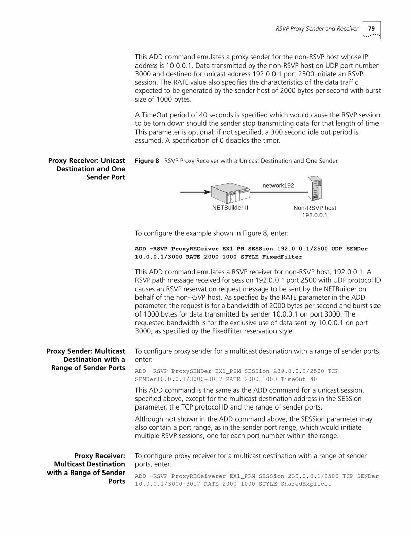
RSVP Proxy Sender and Receiver 79
This ADD command emulates a proxy sender for the non-RSVP host whose IP address is 10.0.0.1. Data transmitted by the non-RSVP host on UDP port number 3000 and destined for unicast address 192.0.0.1 port 2500 initiate an RSVP session. The RATE value also specifies the characteristics of the data traffic expected to be generated by the sender host of 2000 bytes per second with burst size of 1000 bytes.
A TimeOut period of 40 seconds is specified which would cause the RSVP session to be torn down should the sender stop transmitting data for that length of time. This parameter is optional; if not specified, a 300 second idle out period is assumed. A specification of 0 disables the timer.
Proxy Receiver: UnicastDestination and One
Sender Port
Figure 8 RSVP Proxy Receiver with a Unicast Destination and One Sender
To configure the example shown in Figure 8, enter:
ADD -RSVP ProxyRECeiver EX1_PR SESSion 192.0.0.1/2500 UDP SENDer10.0.0.1/3000 RATE 2000 1000 STYLE FixedFilter
This ADD command emulates a RSVP receiver for non-RSVP host, 192.0.0.1. A RSVP path message received for session 192.0.0.1 port 2500 with UDP protocol ID causes an RSVP reservation request message to be sent by the NETBuilder on behalf of the non-RSVP host. As specfied by the RATE parameter in the ADD parameter, the request is for a bandwidth of 2000 bytes per second and burst size of 1000 bytes for data transmitted by sender 10.0.0.1 on port 3000. The requested bandwidth is for the exclusive use of data sent by 10.0.0.1 on port 3000, as specified by the FixedFilter reservation style.
Proxy Sender: MulticastDestination with a
Range of Sender Ports
To configure proxy sender for a multicast destination with a range of sender ports, enter:
ADD -RSVP ProxySENDer EX1_PSM SESSion 239.0.0.2/2500 TCPSENDer10.0.0.1/3000-3017 RATE 2000 1000 TimeOut 40
This ADD command is the same as the ADD command for a unicast session, specified above, except for the multicast destination address in the SESSion parameter, the TCP protocol ID and the range of sender ports.
Although not shown in the ADD command above, the SESSion parameter may also contain a port range, as in the sender port range, which would initiate multiple RSVP sessions, one for each port number within the range.
Proxy Receiver:Multicast Destination
with a Range of SenderPorts
To configure proxy receiver for a multicast destination with a range of sender ports, enter:
ADD -RSVP ProxyRECeiverer EX1_PRM SESSion 239.0.0.1/2500 TCP SENDer10.0.0.1/3000-3017 RATE 2000 1000 STYLE SharedExplicit
Non-RSVP host192.0.0.1
NETBuilder II
network192
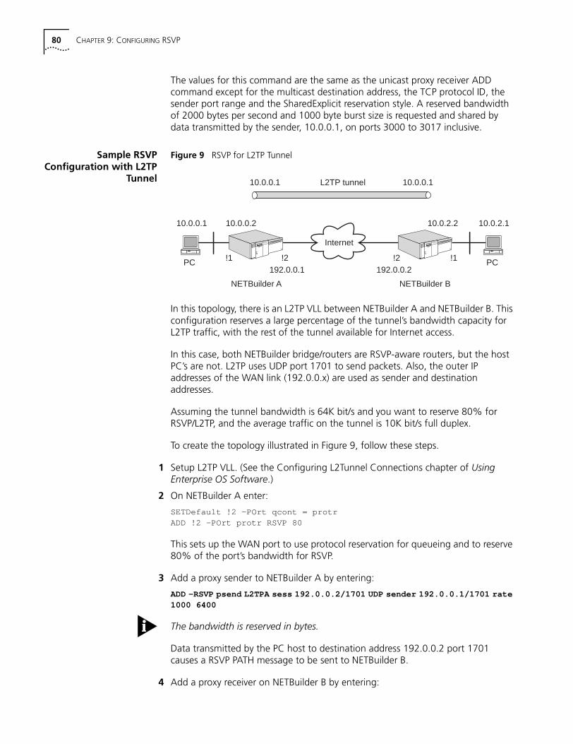
80 CHAPTER 9: CONFIGURING RSVP
The values for this command are the same as the unicast proxy receiver ADD command except for the multicast destination address, the TCP protocol ID, the sender port range and the SharedExplicit reservation style. A reserved bandwidth of 2000 bytes per second and 1000 byte burst size is requested and shared by data transmitted by the sender, 10.0.0.1, on ports 3000 to 3017 inclusive.
Sample RSVPConfiguration with L2TP
Tunnel
Figure 9 RSVP for L2TP Tunnel
In this topology, there is an L2TP VLL between NETBuilder A and NETBuilder B. This configuration reserves a large percentage of the tunnel’s bandwidth capacity for L2TP traffic, with the rest of the tunnel available for Internet access.
In this case, both NETBuilder bridge/routers are RSVP-aware routers, but the host PC’s are not. L2TP uses UDP port 1701 to send packets. Also, the outer IP addresses of the WAN link (192.0.0.x) are used as sender and destination addresses.
Assuming the tunnel bandwidth is 64K bit/s and you want to reserve 80% for RSVP/L2TP, and the average traffic on the tunnel is 10K bit/s full duplex.
To create the topology illustrated in Figure 9, follow these steps.
1 Setup L2TP VLL. (See the Configuring L2Tunnel Connections chapter of Using Enterprise OS Software.)
2 On NETBuilder A enter:
SETDefault !2 -POrt qcont = protrADD !2 -POrt protr RSVP 80
This sets up the WAN port to use protocol reservation for queueing and to reserve 80% of the port’s bandwidth for RSVP.
3 Add a proxy sender to NETBuilder A by entering:
ADD -RSVP psend L2TPA sess 192.0.0.2/1701 UDP sender 192.0.0.1/1701 rate1000 6400
The bandwidth is reserved in bytes.
Data transmitted by the PC host to destination address 192.0.0.2 port 1701 causes a RSVP PATH message to be sent to NETBuilder B.
4 Add a proxy receiver on NETBuilder B by entering:
PC
10.0.0.1
NETBuilder A
PC
NETBuilder B
Internet
10.0.0.2
192.0.0.1 192.0.0.2
10.0.2.2
L2TP tunnel 10.0.0.110.0.0.1
10.0.2.1
!1 !2 !2 !1

RSVP Proxy Sender and Receiver 81
ADD -RSVP prec L2TPB sess 192.0.0.2/1701 UDP sender 192.0.0.1/1701 rate1000 6400 style FixedFilter
A RSVP PATH message received by NETBuilder B for the session from sender 192.0.0.1 on port 1701 causes a RSVP RESV message to be generated which requests the amount of bandwidth as specified by the RATE value in the ADD command.

82 CHAPTER 9: CONFIGURING RSVP
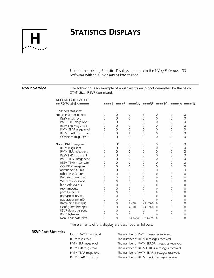
H
STATISTICS DISPLAYSUpdate the existing Statistics Displays appendix in the Using Enterprise OS Software with this RSVP service information.
RSVP Service The following is an example of a display for each port generated by the SHow STATistics -RSVP command:
The elements of this display are described as follows:
RSVP Port Statistics
ACCUMULATED VALUES== RSVPstatistics ===== ====1 ====2 ====3A ====3B ====3C ====4A ====4B
RSVP port statistics:No. of PATH msgs rcvd 0 0 0 81 0 0 0
RESV msgs rcvd 0 0 0 0 0 0 0PATH ERR msgs rcvd 0 0 0 0 0 0 0RESV ERR msgs rcvd 0 0 0 0 0 0 0PATH TEAR msgs rcvd 0 0 0 0 0 0 0RESV TEAR msgs rcvd 0 0 1 0 0 0 0CONFIRM msgs rcvd 0 0 0 0 0 0 0
No. of PATH msgs sent 0 81 0 0 0 0 0RESV msgs sent 0 0 0 0 0 0 0PATH ERR msgs sent 0 0 0 0 0 0 0RESV ERR msgs sent 0 0 0 0 0 0 0PATH TEAR msgs sent 0 0 0 0 0 0 0RESV TEAR msgs sent 0 0 0 0 0 0 0CONFIRM msgs sent 0 0 0 0 0 0 0admission failures 0 0 0 0 0 0 0other resv failures 0 0 0 0 0 0 0Resv sent due to sc 0 0 0 0 0 0 0WF resv w/o scope 0 0 0 0 0 0 0blockade events 0 0 0 0 0 0 0resv timeouts 0 0 0 0 0 0 0path timeouts 0 0 0 0 0 0 0path/ptear rcv ttl0 0 0 0 0 0 0 0path/ptear snt ttl0 0 0 0 0 0 0 0Remaining bw(Bps) 0 0 4800 245760 0 0 0Configured bw(Bps) 0 0 4800 245760 0 0 0RSVP data pkts sent 0 0 0 0 0 0 0RSVP bytes sent 0 0 0 0 0 0 0Non-RSVP data pkts 0 0 148652 504479 0 0 0
No. of PATH msgs rcvd The number of PATH messages received.RESV msgs rcvd The number of RESV messages received.PATH ERR msgs rcvd The number of PATH ERROR messages received.
RESV ERR msgs rcvd The number of RESV ERROR messages received.PATH TEAR msgs rcvd The number of PATH TEAR messages received.RESV TEAR msgs rcvd The number of RESV TEAR messages received.
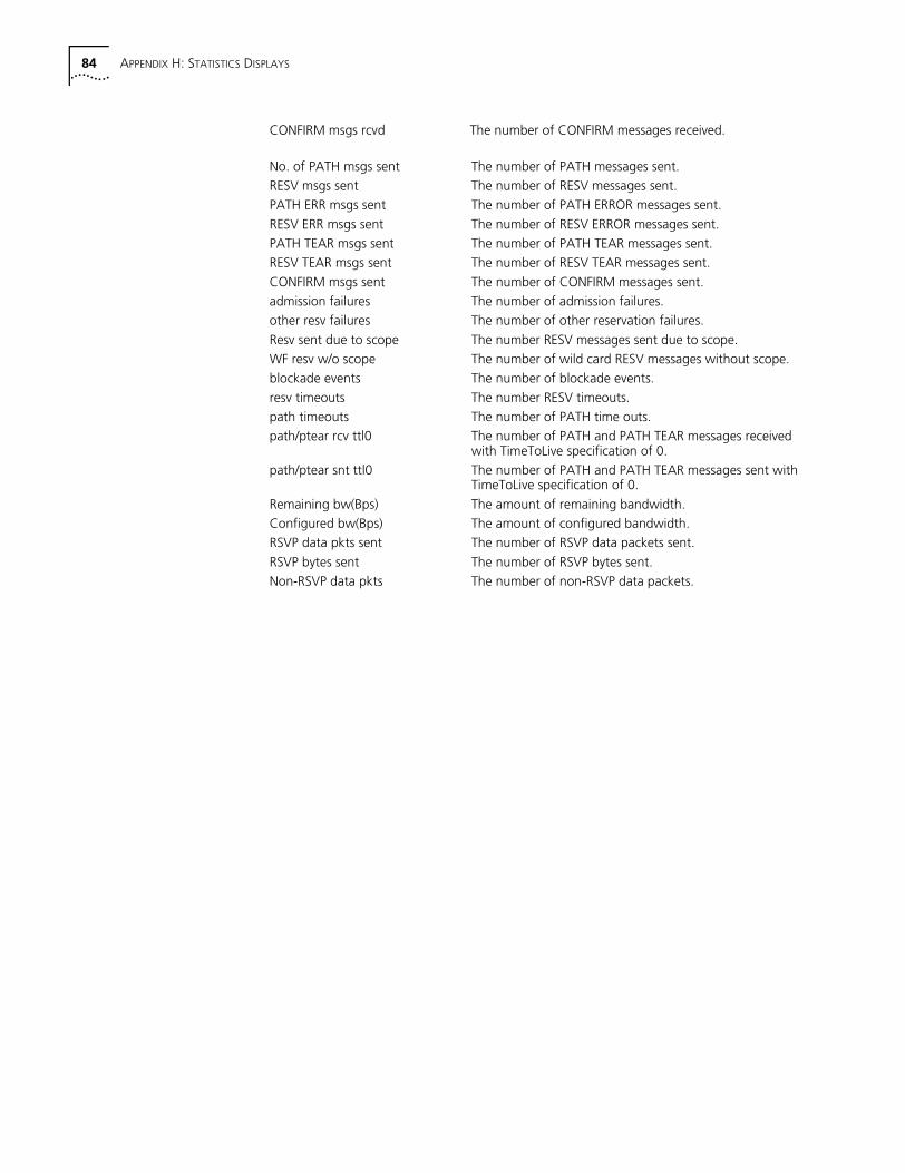
84 APPENDIX H: STATISTICS DISPLAYS
CONFIRM msgs rcvd The number of CONFIRM messages received.
No. of PATH msgs sent The number of PATH messages sent.RESV msgs sent The number of RESV messages sent.PATH ERR msgs sent The number of PATH ERROR messages sent.
RESV ERR msgs sent The number of RESV ERROR messages sent.PATH TEAR msgs sent The number of PATH TEAR messages sent.RESV TEAR msgs sent The number of RESV TEAR messages sent.
CONFIRM msgs sent The number of CONFIRM messages sent.admission failures The number of admission failures.other resv failures The number of other reservation failures.
Resv sent due to scope The number RESV messages sent due to scope.WF resv w/o scope The number of wild card RESV messages without scope.blockade events The number of blockade events.
resv timeouts The number RESV timeouts.path timeouts The number of PATH time outs.path/ptear rcv ttl0 The number of PATH and PATH TEAR messages received
with TimeToLive specification of 0.path/ptear snt ttl0 The number of PATH and PATH TEAR messages sent with
TimeToLive specification of 0.
Remaining bw(Bps) The amount of remaining bandwidth.Configured bw(Bps) The amount of configured bandwidth.RSVP data pkts sent The number of RSVP data packets sent.
RSVP bytes sent The number of RSVP bytes sent.Non-RSVP data pkts The number of non-RSVP data packets.

REFERENCE FOR ENTERPRISE OS SOFTWARE UPDATE PAGES
This section includes update pages with changes and additions to Reference for Enterprise OS Software Version 11.2. These changes relate to the feature enhancements in Enterprise OS software version 11.3
Place the update pages at the front of each specified chapter.

86
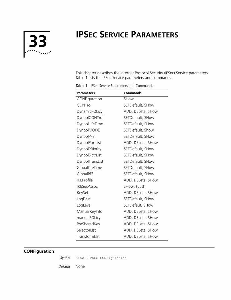
33
IPSEC SERVICE PARAMETERSThis chapter describes the Internet Protocol Security (IPSec) Service parameters. Table 1 lists the IPSec Service parameters and commands.
CONFigurationSyntax SHow -IPSEC CONFiguration
Default None
Table 1 IPSec Service Parameters and Commands
Parameters Commands
CONFiguration SHow
CONTrol SETDefault, SHow
DynamicPOLicy ADD, DELete, SHow
DynpolCONTrol SETDefault, SHow
DynpolLifeTime SETDefault, SHow
DynpolMODE SETDefault, Show
DynpolPFS SETDefault, SHow
DynpolPortList ADD, DELete, SHow
DynpolPRIority SETDefault, SHow
DynpolSlctrLIst SETDefault, SHow
DynpolTransLIst SETDefault, SHow
GlobalLifeTime SETDefault, SHow
GlobalPFS SETDefault, SHow
IKEProfile ADD, DELete, SHow
IKESecAssoc SHow, FLush
KeySet ADD, DELete, SHow
LogDest SETDefault, SHow
LogLevel SETDefaut, SHow
ManualKeyInfo ADD, DELete, SHow
manualPOLicy ADD, DELete, SHow
PreSharedKey ADD, DELete, SHow
SelectorLIst ADD, DELete, SHow
TransformLIst ADD, DELete, SHow
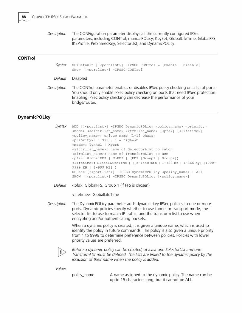
88 CHAPTER 33: IPSEC SERVICE PARAMETERS
Description The CONFiguration parameter displays all the currently configured IPSec parameters, including CONTrol, manualPOLicy, KeySet, GlobalLifeTime, GlobalPFS, IKEProfile, PreSharedKey, SelectorLIst, and DynamicPOLicy.
CONTrolSyntax SETDefault [!<portlist>] -IPSEC CONTrol = [Enable | Disable]
SHow [!<portlist>] -IPSEC CONTrol
Default Disabled
Description The CONTrol parameter enables or disables IPSec policy checking on a list of ports. You should only enable IPSec policy checking on ports that need IPSec protection. Enabling IPSec policy checking can decrease the performance of your bridge/router.
DynamicPOLicy
Syntax ADD [!<portlist>] –IPSEC DynamicPOLicy <policy_name> <priority><mode> <selctrlist_name> <xfrmlist_name> [<pfs>] [<lifetime>]<policy_name>: unique name (1-15 chars)<priority>: 1-9999 , 1 = highest<mode>: Tunnel | Xport<slctrlist_name>: name of SelectorLIst to match<xfrmlist_name>: name of TransformLIst to use<pfs>: GlobalPFS | NoPFS | (PFS [Group1 | Group2])<lifetime>: GlobalLifeTime | ([5-1440 min | 1-720 hr | 1-366 dy] [1000-9999 KB | 1-999 MB] )DELete [!<portlist>] –IPSEC DynamicPOLicy <policy_name> | AllSHOW [!<portlist>] –IPSEC DynamicPOLicy [<policy_name>]
Default <pfs>: GlobalPFS, Group 1 (if PFS is chosen)
<lifetime>: GlobalLifeTime
Description The DynamicPOLicy parameter adds dynamic-key IPSec policies to one or more ports. Dynamic policies specify whether to use tunnel or transport mode, the selector list to use to match IP traffic, and the transform list to use when encrypting and/or authenticating packets.
When a dynamic policy is created, it is given a unique name, which is used to identify the policy in future commands. The policy is also given a unique priority from 1 to 9999 to determine preference between policies. Policies with lower priority values are preferred.
Before a dynamic policy can be created, at least one SelectorLIst and one TransformLIst must be defined. The lists are linked to the dynamic policy by the inclusion of their name when the policy is added.
Values
policy_name A name assigned to the dynamic policy. The name can be up to 15 characters long, but it cannot be ALL.
DynpolCONTrol 89
DynpolCONTrol
Syntax SETDefault !<policy_name> DynpolCONTrol = Disable | EnableSHOW [!<policy_name>] DynpolCONTrol
Default None
Description The DynpolCONTrol parameter is used to disable or enable a dynamic IPSec policy. If a policy is disabled, it is be ignored and packets that might match the selector list associated with the policy are no longer be processed according to the dynamic policy. If no other IPSec policies match the traffic, the traffic is sent unencrypted. By default, a dynamic policy is enabled when it is added.
To reset security associations of a policy, using this parameter, enter:
SETDefault !<policy_name> DynpolCONTrol = Enable
priority Specifies the preference of the policy among the other dynamic policies on the system. If a packet matches the selectors of several policies, the dynamic policy with the lowest priority value is applied.
mode Selects Tunnel or Transport mode for the IPSec security association associated with the policy.
selectrlist_name The name of a selector list that was previously-defined with the SelectorLIst parameter. Packets matching the definitions in the selector list match the IPSec policy and are processed accordingly.
xfrmlist_name The name of a transform list that was previously defined with the TransformLIst parameter. The transform list is used to negotiate IPSec security associations, and packets processed by this policy are encrypted and/or authenticated according to the negotiated transforms’ security associations. Also, packets processed by the policy are encrypted and/or authenticated according to the negotiated transforms.
pfs Selects the Perfect Forward Secrecy mode to use with the selected transforms. Choose PFS or PFS Group2 to provide additional security at the cost of performance. Choose NoPFS to prevent PFS from being used with the policy. By default, the value set in GlobalPFS is used with the policy. For peers to negotiate, their pfs settings must match exactly.
lifetime Sets the lifetime for security associations created by this policy. Specify the lifetime in units of minutes (m), hours (h), or days (d) and/or kilobytes (kb) or megabytes (mb). By default the value in GlobalLifeTime will be used with the policy.
90 CHAPTER 33: IPSEC SERVICE PARAMETERS
DynpolLifeTime
syntax SETDefault !<policy_name> –IPSEC DynpolLifeTime = GlobalLifeTime |([5-1440min | 1-720hr | 1-366dy] [1000-9999KB | 1-9999MB])SHOW [!<policy_name>] –IPSEC DynpolLifeTime
Default None
Description The DynpolLifeTime parameter changes the lifetime setting of a dynamic policy. LifeTime may be expressed in time and/or data units as indicated in the syntax. Before the dynamic-key security association’s lifetime is expired, a new security association is set up. When the security association expires, the traffic must be forwarded on the new security association. By specifying GlobalLifeTime, the value set in the GlobalLifeTime parameter is used for the policy.
DynpolMODE
Syntax SETDefault !<policy_name> -IPSEC DynpolMODE = Tunnel | XportSHOW [!<policy_name>] –IPSEC DynpolMODE
Default None
Description The DynpolMODE parameter is used to change the IPSec mode for a dynamic policy to Tunnel or transport (Xport). Tunnel mode may be used only on IP-IP tunnel virtual ports.
DynpolPFS
Syntax SETDefault !<policy_name> –IPSEC DynpolPFS = GlobalPFS | NoPFS | (PFS[Group1 | Group2])SHOW [!<policy_name>] –IPSEC DynpolPFS
Default Group1 (if PFS is chosen)
Description The DynpolPFS parameter specifies whether perfect forward secrecy (PFS) are used by an IPSec dynamic policy. To enable it, choose PFS with either Group1 (default) or Group2 to specify a 768-bit or a 1024-bit Diffie Hellman group, respectively. If PFS is not desired, choose NoPFS. If GlobalPFS is used, the policy uses the setting in the GlobalPFS parameter.
Setting the value to PFS causes the system to negotiate a new shared secret with an IPSec peer every time a new key is needed. (This negotiation involves intense numerical calculations that may degrade performance while renegotiations are in progress.) For peers to negotiate successfully, their PFS settings must match exactly.
Examples To enable PFS using a 768-bit Diffie-Hellman group for dynamic policy policy1, enter:
SETDefault !policy1 –IPSEC DynpolPFS = PFS
To select PFS for dynamic policy policy2, and use a 1024-bit Diffie-Hellman group instead, enter:
DynpolPortList 91
SETDefault !policy2 –IPSEC DynpolPFS = PFS Group2
DynpolPortList
Syntax ADD !<portlist> -IPSEC DynpolPortList <policy_name>DELete !<portlist> -IPSEC DynpolPortList <policy_name>SHOW –IPSEC PortList [<policy_name>]
Default None
Description The PortList parameter is used to add or delete ports from an IPSec dynamic policy. This allows additional ports to be secured without entering new policies. The dynamic policy has the same settings across all ports on which it is defined.
Example To add virtual ports !v28 through !v30 to the existing dynamic policy, policy3, enter:
ADD !v28-!v30 –IPSEC DynpolPortList policy3
DynpolPRIority
Syntax SETDefault !<policy_name> -IPSEC DynpolPRIority = 1-9999SHOW [!<policy_name>] –IPSEC DynpolPRIority
Default: None
Description: The PRIority parameter changes the priority of a specific IPSec dynamic policy. Lower numbered policies have higher precedence and are matched before higher numbered policies. PRIority must be unique for each dynamic policy entered on the system. This parameter can be used to adjust the priorities of dynamic policies when the existing priorities prevent the correct policy from being chosen for a particular set of IP traffic.
DynpolSlctrLIst
Syntax SETDefault !<policy_name> -IPSEC DynpolSlctrLIst = <slctrlist_name>SHOW [!<policy_name>] –IPSEC DynpolSlctrLIst
Default None
Description The DynpolSlctrLIst parameter is used to change which selector list is used by a dynamic policy. The selector list must be defined before a policy can use it.
Example To change the selector list used by existing IPSec dynamic policy policy2 to selector list selector2, enter:
SETDefault !policy2 –IPSEC DynpolSlctrLIst = selector2
DynpolTransLIst
Syntax SETDefault !<policy_name> -IPSEC DynpolTransLIst = <Xfrmlist_name>SHOW [!<policy_name>] –IPSEC DynpolTransLIst
92 CHAPTER 33: IPSEC SERVICE PARAMETERS
Default None
Description The DynpolTransLIst parameter is used to change which transform list is used by a dynamic policy. The transform list must be defined before a policy can use it.
GlobalLifeTime
Syntax SETDefault -IPSEC GlobalLifeTime = ([5-1440 min | 1-720 hr | 1-366 dy][1000-9999 KB | 1-9999 MB])SHOW –IPSEC GlobalLifeTime
Default 1hr
Description The GlobalLifeTime parameter sets the global default lifetime to be used with all dynamic policies with lifetimes configured using the GlobalLifeTime setting. This lifetime may be entered in units of time and/or data. This specifies the maximum elapsed time and/or the amount of data that can be forwarded on an IPSec security association before it expires. A new security association is negotiated before the first expires so that traffic continues to flow with IPSec protection when the first security association expires.
The GlobalLifeTime parameter does not affect IKE security associations. Those security associations use the lifetime specified by the IKEProfile settings.
GlobalPFS
Syntax SETDefault -IPSEC GlobalPFS = NoPFS | (PFS [Group1 | Group2])SHOW –IPSEC GlobalLifeTime
Default NoPFS, Group1 (if PFS is chosen)
Description The GlobalPFS parameter sets the global default PFS to be used by all dynamic policies with PFS set to GlobalPFS. The GlobalPFS setting is NoPFS by default, but if additional security is required, the setting should be set to PFS. Setting the value to PFS causes the system to negotiate a new shared secret with an IPSec peer every time a new key is needed. (This negotiation involves intense numerical calculations that may degrade performance while renegotiations are in progress.) For peers to negotiate successfully, their PFS settings must match exactly.
IKEProfile
Syntax ADD –IPSEC IKEProfile <priority> [<auth_method>][<encrypt_alg>] [<hash_alg>][<dh_group>] [<lifetime>]<priority>: 1-9999 , 1 = highest<auth_method>: PreSharedKey<encrypt_xfrms>: 3DES, DES<hash_xfrms>: MD5, SHA<lifetime>: 5-1440 min | 1-720 hr | 1-366 dy<dh_group>: Group1 | Group2DELete –IPSEC IKEProfile All | <profile_name>SHOW –IPSEC IKEProfile [<profile_name>]
IKEProfile 93
Defaults <auth_method> PreSharedKey
<excrypt_xfrms> DES
<hash_xfrms> MD5
<lifetime> 8 hr
<dh_group> Group1
Description The IKEProfile parameter defines the security settings to use when setting up IKE (Phase 1) security associations. IKE security associations protect key exchanges and negotiations for IPSec (Phase 2) security associations.The settings include: authentication method, encryption algorithm, hash algorithm, lifetime, and the Diffie-Hellman group to use in negotiations. All the settings are optional, and any settings that are omitted assume default values.
Several IKE profiles can be added. IKE attempts to use the profiles in the order of priority. If a profile cannot be used when negotiating with a peer due to a lack of configured information, the next profile is attempted.
If no IKEProfiles are added, a default IKEProfile exists that uses all the default settings. Once a custom IKEProfile has been added, the default profile is no longer available to use when setting up new IKE security associations. However, the default IKE profile returns if all the IKE profiles are deleted.
Values
priority A unique integer from 1 to 9999 to indicate the preference of the profile. The lower the number, the higher the priority of the profile. (It is advisable to leave “gaps” between priority values so that new profiles can be inserted before or between existing ones.)
auth_method The authentication method used for the IKE security association. By default, PreSharedKeys is selected.
encrypt_alg The encryption transform used for the IKE security association. By default, DES is used. Acceptable values are:
■ 3DES Triple DES (Data Encryption Standard)
■ DES Data Encryption Standard
hash_alg The hash transform used for the IKE security association. By default, the MD5 hash is used. Acceptable values for the hash transform are:
■ MD5 The MD5 hash algorithm
■ SHA The SHA hash algorithm
dh_group The Diffie-Hellman group to use when negotiating the shared secret used for keying material. The default, Group1, specifies the 768-bit D-H group. Group2 specifies a 1024-bit D-H group which provides additional security but requires additional CPU resources during negotiation.
94 CHAPTER 33: IPSEC SERVICE PARAMETERS
Example To define IKE profiles to allow negotiation using 3DES or DES (default) encryption and either MD5 (default), or SHA hash with the default authentication method, dh_group, and lifetime, enter:
ADD -IPSEC IKEProfile 100 3DESADD -IPSEC IKEProfile 200 3DES SHAADD -IPSEC IKEProfile 300ADD -IPSEC IKEProfile 400 SHA
IKESecAssocSyntax SHow -IPSEC IKESecAssoc [<peer_id>]
FLush -IPSEC IKESecAssoc <peer_id> | All
Description The IKESecAssoc parameter displays the the IPSec Phase 1 (Internet Key Exchange) security associations negotiated with peers as needed by dynamic-key IPSec policies. If peer_id is specified, only the Phase 1 security associations for that peer are shown.
IKE security associations may be deleted by using the FLush command with this parameter. Either a specific peer address, or the keyword “All” must be specified when flushing Phase 1 security associations.
KeySetSyntax ADD -IPSEC KeySet <keyset_name> [EncryptKey (“<ascii_text>” |
%<hex_string>)] [AuthKey (“<ascii_text>” | %<hex_string>)]DELete -IPSEC KeySet [<key_set_name> | ALL]SHow -IPSEC KeySet [<key_set_name>]
Description The KeySet parameter adds manual encryption and authentication keys. Key values can be entered as either ASCII text strings or as a series of hexadecimal digits. The text or hex key values are converted to actual key values for each supported encryption and authentication algorithm.
When key sets are displayed using the SHow command, encoded values for the keys, instead of the actual values, are displayed for added security. The encoded key value is unique for each key value and can be used to verify that keys match between different routers.
The encrypt_key and auth_key must match the values on the peer system at the other end of the security association. When keys are entered, no particular length restriction is applied. Keys can be entered as either ASCII text or hex values in the range of 1 to 128 bytes.
When an encryption key is bound to a policy, length restrictions are applied based on the encryption transform and the software package in use. The xE packages
lifetime The proposed length of time that elapses before the IKE security association (SA) expires. After expiration, a new IKE SA must be established. If two peers propose different lifetimes, the lower of the proposals will be used for the security association.
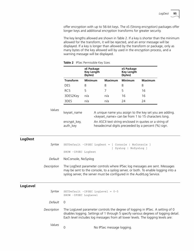
LogDest 95
offer encryption with up to 56-bit keys. The xS (Strong encryption) packages offer longer keys and additional encryption transforms for greater security.
The key lengths allowed are shown in Table 2. If a key is shorter than the minimum allowed for the transform, it will be rejected, and an error message will be displayed. If a key is longer than allowed by the transform or package, only as many bytes of the key allowed will by used in the encryption process, and a warning message will be displayed.
Values
LogDestSyntax SETDefault -IPSEC LogDes t = [ Console | NoConsole ]
[ SysLog | NoSysLog ]SHOW -IPSEC LogDest
Default NoConsole, NoSyslog
Description The LogDest parameter controls where IPSec log messages are sent. Messages may be sent to the console, to a syslog server, or both. To enable logging into a syslog server, the server must be configured in the AuditLog Service.
LogLevelSyntax SETDefault -IPSEC LogLevel = 0-5
SHOW -IPSEC LogLevel
Default 0
Description The LogLevel parameter controls the degree of logging in IPSec. A setting of 0 disables logging. Settings of 1 through 5 specify various degrees of logging detail. Each level includes log messages from all lower levels. The logging levels are:
Values
Table 2 IPSec Permissible Key Sizes
xE Package Key Length (bytes)
xS Package Key Length (bytes)
Transform Minimum Maximum Minimum Maximum
DES 8 8 8 8
RC5 5 7 5 16
3DES2Key n/a n/a 16 16
3DES n/a n/a 24 24
keyset_name A unique name you assign to the key set you are adding. <keyset_name> can be from 1 to 15 characters long.
encrypt_key, auth_key
An ASCII text string enclosed in quotes or a string of hexadecimal digits preceeded by a percent (%) sign.
0 No IPSec message logging.
96 CHAPTER 33: IPSEC SERVICE PARAMETERS
ManualKeyInfoSyntax SETDefault!<portlist>-IPSECManualKeyInfo<policy_name>[<peer_ipaddr>]
(<keyset_name> | NONE) [SpiEsp <spi_in> <spi_out>] [SpiAh <spi_in><spi_out>]SHow !<portlist> -IPSEC ManualKeyInfo [<policy_name>]
Description The ManualKeyInfo parameter adds manual keying information to an IPSec policy and key set. Only one ManualKeyInfo command can be applied to each policy. To change the manual keying information after it has been applied to a policy, you must first delete the information using the NONE as the key set name, then add the new information using SETDefault with the new key set name.
The ManualKeyInfo parameter creates one or two pairs of security associations between the local router and the destination router.
Values
manualPOLicySyntax ADD !<portlist> -IPSEC manualPOLicy <policy_name> <action> (DEFault |
{<filters> <src_ipaddr/mask>(<dst_ipaddr/mask> | DYNamic)})[<encrypt_alg>] [<auth_alg>]<action>: AhEspXport | AhTunnel | AhXport | EspAuthTunnel | EspAuthXport |EspTunnel | EspXport<filters>: ANY | (GRE, ICMP, OSPF, TCP[(<port>,<port>)...up to 16 pairs],UDP[(<port>,<port>)...up to 16 pairs])<encrypt_alg>:3DES | 3DES2key | DES | RC5 | NULL<auth_alg>: MD5 | SHA
1 Logs only authentication failures.
2 Adds other negotiation failures.
3 Adds IPSec (Phase 2) session creation and deletion messages.
4 Adds IKE (Phase 1) session creation and deletion messages.
5 Adds session rekeying messages.
policy_name A name you assigned to a policy you added using the POLicy parameter.
peer_ipaddr The IP address of the peer host which is only required for tunnel mode policies on P2MP IPIP ports.
keyset_name | NONE
A name you assigned to a key set you added using the KeySet parameter. If you specify NONE, the manual key information is removed from the policy.
spi_in A number in the range 256 to 2000. All spi_in values must be unique on a system. spi_in must match the spi_out value specified on the peer system at the other end of the security association.
spi_out A number in the range 256 to 2147483647. spi_out must match the spi_in value specified on the peer system at the other end of the security association. spi_out may be equal to spi_in.
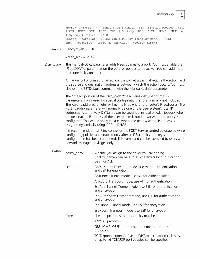
manualPOLicy 97
<port>: 1-65535 | * | Archie | DNS | Finger | FTP | FTPData |Gopher | HTTP| NFS | NNTP | NTP | POP2 | POP3 | PortMap | RIP | SMTP | SNMP | SNMPtrap| Syslog | Telnet | WAISDELete !<portlist> -IPSEC manualPOLicy (<policy_name> | ALL)SHow !<portlist> -IPSEC manualPOLicy [<policy_name>]
Defaults <encrypt_alg> = DES
<auth_alg> = MD5
Description The manualPOLicy parameter adds IPSec policies to a port. You must enable the IPSec CONTrol parameter on the port for policies to be active. You can add more than one policy on a port.
A manual policy consists of an action, the packet types that require the action, and the source and destination addresses between which the action occurs.You must also use the SETDefault command with the ManualKeyInfo parameter.
The “mask” portion of the <scr_ipaddr/mask> and <dst_ipaddr/mask> parameters is only used for special configurations and is normally not included. The <src_ipaddr> parameter will normally be one of the router’s IP addresses. The <dst_ipaddr> parameter will normally be one of the peer system’s local IP addresses. Alternatively, DYNamic can be specified instead of <dst_ipaddr> when the destination IP address of the peer system is not known when the policy is configured. This would apply in cases where the peer system’s IP address is assigned dynamically using IPCP or DHCP.
It is recommended that IPSec control or the PORT Service control be disabled while configuring policies and enabled only after all IPSec policy and key set configuration has been completed. This command can be executed by users with network manager privileges only.
Valuespolicy_name A name you assign to the policy you are adding.
<policy_name> can be 1 to 15 characters long, but cannot be all or ALL.
action AhEspXport: Transport mode, use AH for authentication and ESP for encryption.
AhTunnel: Tunnel mode, use AH for authentication.
AhXport: Transport mode, use AH for authentication.
EspAuthTunnel: Tunnel mode, use ESP for authentication and encryption.
EspAuthXport: Transport mode, use ESP for authentication and encryption.
EspTunnel: Tunnel mode, use ESP for encryption.
EspXport: Transport mode, use ESP for encryption.
filters Lists the protocols that this policy matches.
ANY: all protocols.
GRE, ICMP, OSPF: pre-defined mnemonics for these protocols.
TCP[(<port>, <port>)...] and UDP[(<port>, <port>)...]: A list of up to 16 TCP/UDP port couples can be specified.
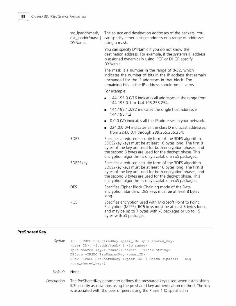
98 CHAPTER 33: IPSEC SERVICE PARAMETERS
PreSharedKey
Syntax ADD –IPSEC PreSharedKey <peer_ID> <pre-shared_key><peer_ID>: <ipaddr/mask> | <ip_range><pre-shared_key>: “<ascii-text>” | %<hex-string>DELete –IPSEC PreSharedKey <peer_ID>SHow –IPSEC PreSharedKey [<peer_ID> | Match <ipaddr> | Sig<pre_shared_key>]
Default None
Description The PreSharedKey parameter defines the preshared keys used when establishing IKE security associations using the preshared key authentication method. The key is associated with the peer or peers using the Phase 1 ID specified in
src_ipaddr/mask, dst_ipaddr/mask | DYNamic
The source and destination addresses of the packets. You can specify either a single address or a range of addresses using a mask.
You can specify DYNamic if you do not know the destination address. For example, if the system’s IP address is assigned dynamically using IPCP or DHCP, specify DYNamic.
The mask is a number in the range of 0-32, which indicates the number of bits in the IP address that remain unchanged for the IP addresses in that block. The remaining bits in the IP address should be all zeros.
For example:
■ 144.195.0.0/16 indicates all addresses in the range from 144.195.0.1 to 144.195.255.254.
■ 144.195.1.2/32 indicates the single host address is 144.195.1.2.
■ 0.0.0.0/0 indicates all the IP addresses in your network.
■ 224.0.0.0/4 indicates all the class D multicast addresses, from 224.0.0.1 through 239.255.255.254.
3DES Specifies a reduced-security form of the 3DES algorithm. 3DES2key keys must be at least 16 bytes long. The first 8 bytes of the key are used for both encryption phases, and the second 8 bytes are used for the decrypt phase. This encryption algorithm is only available on xS packages.
3DES2key Specifies a reduced-security form of the 3DES algorithm. 3DES2key keys must be at least 16 bytes long. The first 8 bytes of the key are used for both encryption phases, and the second 8 bytes are used for the decrypt phase. This encryption algorithm is only available on xS packages.
DES Specifies Cipher Block Chaining mode of the Data Encryption Standard. DES keys must be at least 8 bytes long.
RC5 Specifies encryption used with Microsoft Point to Point Encryption (MPPE). RC5 keys must be at least 5 bytes long, and may be up to 7 bytes with xE packages or up to 15 bytes with xS packages.
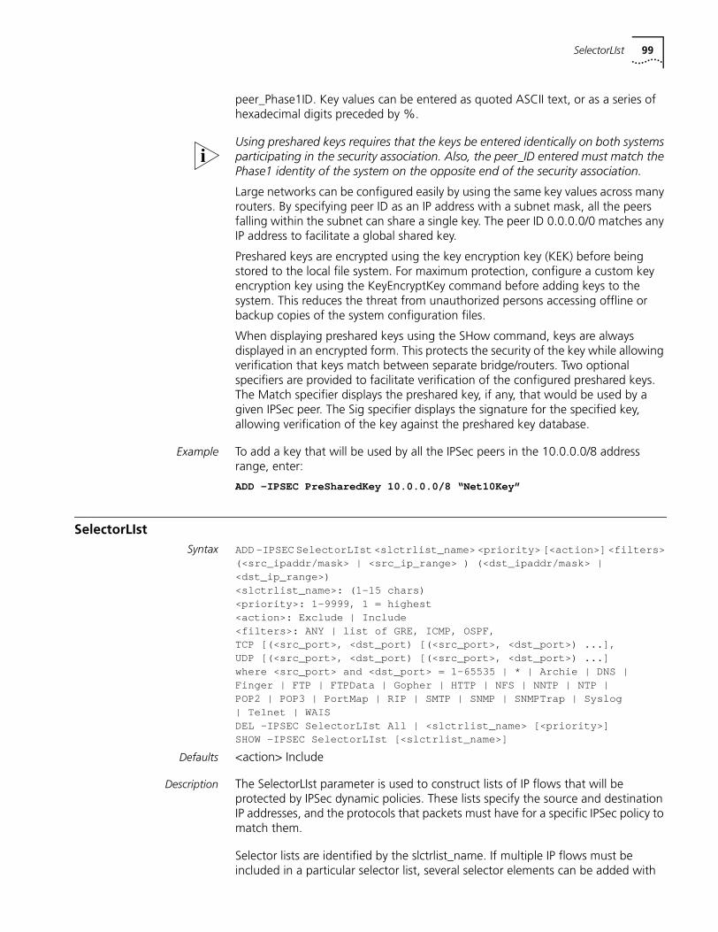
SelectorLIst 99
peer_Phase1ID. Key values can be entered as quoted ASCII text, or as a series of hexadecimal digits preceded by %.
Using preshared keys requires that the keys be entered identically on both systems participating in the security association. Also, the peer_ID entered must match the Phase1 identity of the system on the opposite end of the security association.
Large networks can be configured easily by using the same key values across many routers. By specifying peer ID as an IP address with a subnet mask, all the peers falling within the subnet can share a single key. The peer ID 0.0.0.0/0 matches any IP address to facilitate a global shared key.
Preshared keys are encrypted using the key encryption key (KEK) before being stored to the local file system. For maximum protection, configure a custom key encryption key using the KeyEncryptKey command before adding keys to the system. This reduces the threat from unauthorized persons accessing offline or backup copies of the system configuration files.
When displaying preshared keys using the SHow command, keys are always displayed in an encrypted form. This protects the security of the key while allowing verification that keys match between separate bridge/routers. Two optional specifiers are provided to facilitate verification of the configured preshared keys. The Match specifier displays the preshared key, if any, that would be used by a given IPSec peer. The Sig specifier displays the signature for the specified key, allowing verification of the key against the preshared key database.
Example To add a key that will be used by all the IPSec peers in the 10.0.0.0/8 address range, enter:
ADD –IPSEC PreSharedKey 10.0.0.0/8 “Net10Key”
SelectorLIstSyntax ADD –IPSEC SelectorLIst <slctrlist_name> <priority> [<action>] <filters>
(<src_ipaddr/mask> | <src_ip_range> ) (<dst_ipaddr/mask> |<dst_ip_range>)<slctrlist_name>: (1-15 chars)<priority>: 1-9999 , 1 = highest<action>: Exclude | Include<filters>: ANY | list of GRE, ICMP, OSPF,TCP [(<src_port>, <dst_port) [(<src_port>, <dst_port>) ...],UDP [(<src_port>, <dst_port) [(<src_port>, <dst_port>) ...]where <src_port> and <dst_port> = 1-6553 5 | * | A rchie | DNS |Finger | FTP | FTPData | Gopher | HTTP | NFS | NNTP | NTP |POP2 | POP3 | PortMap | RIP | SMTP | SNMP | SNMPTrap | Syslog| Telnet | WAISDEL –IPSEC SelectorLIst All | <slctrlist_name> [<priority>]SHOW –IPSEC SelectorLIst [<slctrlist_name>]
Defaults <action> Include
Description The SelectorLIst parameter is used to construct lists of IP flows that will be protected by IPSec dynamic policies. These lists specify the source and destination IP addresses, and the protocols that packets must have for a specific IPSec policy to match them.
Selector lists are identified by the slctrlist_name. If multiple IP flows must be included in a particular selector list, several selector elements can be added with
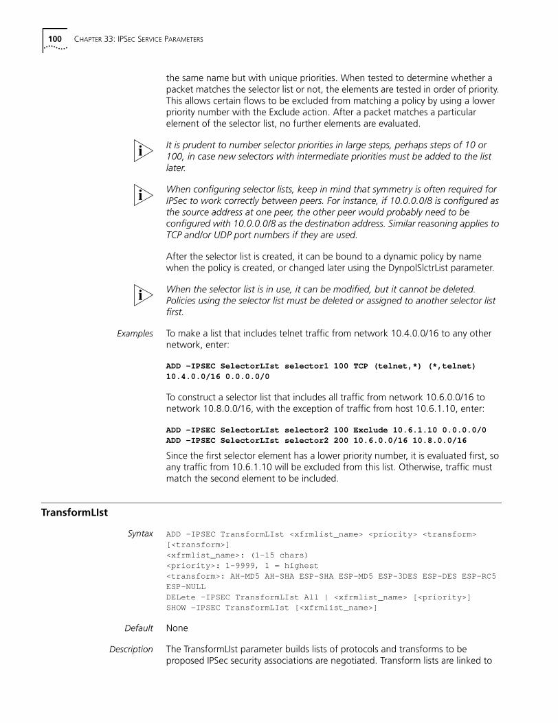
100 CHAPTER 33: IPSEC SERVICE PARAMETERS
the same name but with unique priorities. When tested to determine whether a packet matches the selector list or not, the elements are tested in order of priority. This allows certain flows to be excluded from matching a policy by using a lower priority number with the Exclude action. After a packet matches a particular element of the selector list, no further elements are evaluated.
It is prudent to number selector priorities in large steps, perhaps steps of 10 or 100, in case new selectors with intermediate priorities must be added to the list later.
When configuring selector lists, keep in mind that symmetry is often required for IPSec to work correctly between peers. For instance, if 10.0.0.0/8 is configured as the source address at one peer, the other peer would probably need to be configured with 10.0.0.0/8 as the destination address. Similar reasoning applies to TCP and/or UDP port numbers if they are used.
After the selector list is created, it can be bound to a dynamic policy by name when the policy is created, or changed later using the DynpolSlctrList parameter.
When the selector list is in use, it can be modified, but it cannot be deleted. Policies using the selector list must be deleted or assigned to another selector list first.
Examples To make a list that includes telnet traffic from network 10.4.0.0/16 to any other network, enter:
ADD –IPSEC SelectorLIst selector1 100 TCP (telnet,*) (*,telnet)10.4.0.0/16 0.0.0.0/0
To construct a selector list that includes all traffic from network 10.6.0.0/16 to network 10.8.0.0/16, with the exception of traffic from host 10.6.1.10, enter:
ADD –IPSEC SelectorLIst selector2 100 Exclude 10.6.1.10 0.0.0.0/0ADD –IPSEC SelectorLIst selector2 200 10.6.0.0/16 10.8.0.0/16
Since the first selector element has a lower priority number, it is evaluated first, so any traffic from 10.6.1.10 will be excluded from this list. Otherwise, traffic must match the second element to be included.
TransformLIst
Syntax ADD –IPSEC TransformLIst <xfrmlist_name> <priority> <transform>[<transform>]<xfrmlist_name>: (1-15 chars)<priority>: 1-9999 , 1 = highest<transform>: AH-MD5 AH-SHA ESP-SHA ESP-MD5 ESP-3DES ESP-DES ESP-RC5ESP-NULLDELete –IPSEC TransformLIst All | <xfrmlist_name> [<priority>]SHOW –IPSEC TransformLIst [<xfrmlist_name>]
Default None
Description The TransformLIst parameter builds lists of protocols and transforms to be proposed IPSec security associations are negotiated. Transform lists are linked to
TransformLIst 101
IPSec dynamic policies as they are added, or they are linked later through the DynpolXformList parameter.
After a transform list is linked to a policy, it can be modified, but it cannot be deleted. Policies using the transform list must be deleted or assigned to another transform list first.
Elements of transform lists are entered as one or two protocol-transform keywords. An element may contain up to one encryption and up to one authentication protocol-transform pair. Several elements can be added to a transform list by adding a new element with the same name, but a different priority. Transform list elements are proposed in the order of priority. The actual transforms that are used are the result of negotiation between IPSec peers. These results depend upon the configuration of both peers.
The encryption transforms available are:
■ ESP-3DES: Use 3DES encryption with the ESP protocol.
■ ESP-DES: Use DES encryption with the ESP protocol.
■ ESP-RC5: Use RC5 encryption with the ESP protocol.
■ ESP-NULL: Do not encrypt (used with ESP-authentication).
The authentication transforms available are:
■ AH-MD5: Use MD5 authentication with the AH protocol.
■ AH-SHA: Use SHA authentication with the AH protocol.
■ ESP-MD5: Use MD5 authentication with the ESP protocol.
■ ESP-SHA: Use SHA authentication with the ESP protocol.
Examples To create a transform list trans1, which will propose ESP with DES encryption and SHA authentication, enter:
ADD -IPSEC TransformLIst trans1 100 ESP-DES ESP-SHA
To add a second proposal with a lower priority to transform list trans1 for ESP DES encryption and AH with SHA authentication, enter:
ADD -IPSEC TransformLIst trans1 200 ESP-DES AH-SHA

102 CHAPTER 33: IPSEC SERVICE PARAMETERS
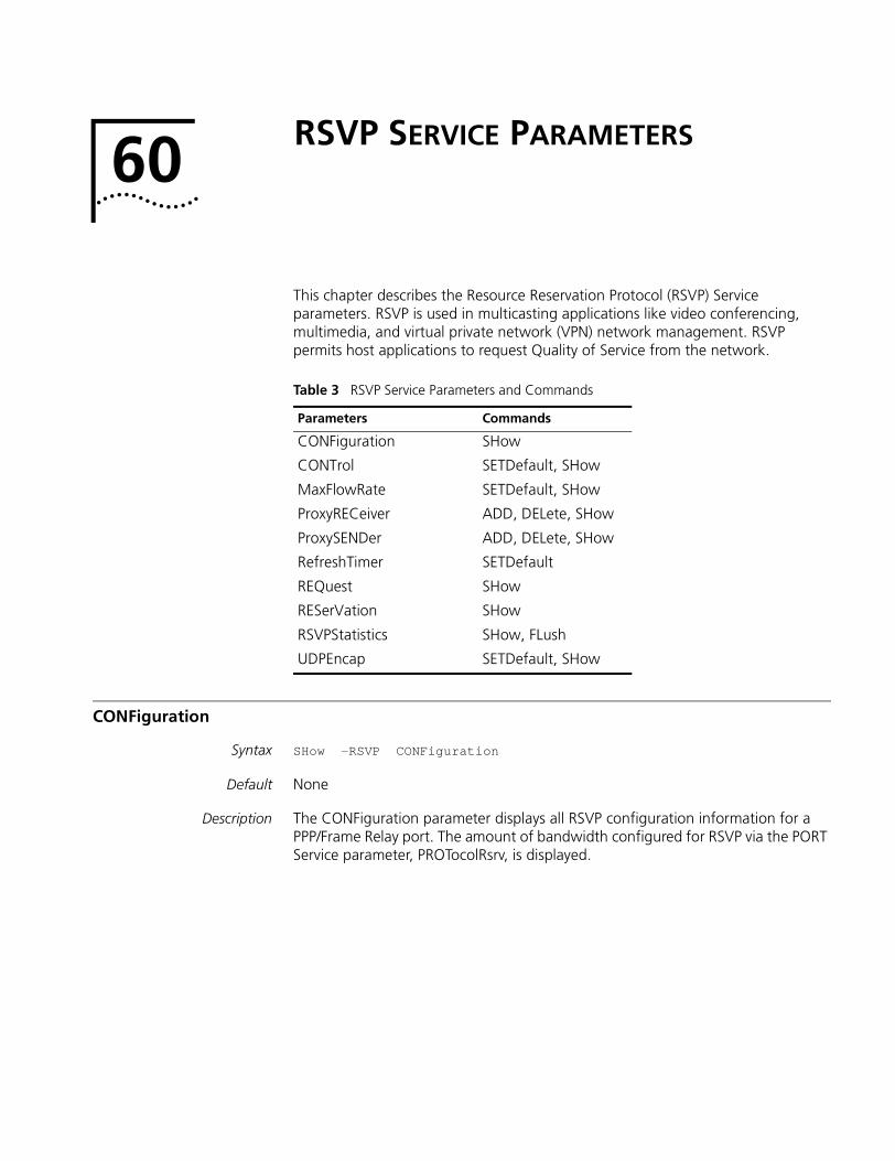
60
RSVP SERVICE PARAMETERSThis chapter describes the Resource Reservation Protocol (RSVP) Service parameters. RSVP is used in multicasting applications like video conferencing, multimedia, and virtual private network (VPN) network management. RSVP permits host applications to request Quality of Service from the network.
CONFiguration
Syntax SHow -RSVP CONFiguration
Default None
Description The CONFiguration parameter displays all RSVP configuration information for a PPP/Frame Relay port. The amount of bandwidth configured for RSVP via the PORT Service parameter, PROTocolRsrv, is displayed.
Table 3 RSVP Service Parameters and Commands
Parameters Commands
CONFiguration SHow
CONTrol SETDefault, SHow
MaxFlowRate SETDefault, SHow
ProxyRECeiver ADD, DELete, SHow
ProxySENDer ADD, DELete, SHow
RefreshTimer SETDefault
REQuest SHow
RESerVation SHow
RSVPStatistics SHow, FLush
UDPEncap SETDefault, SHow
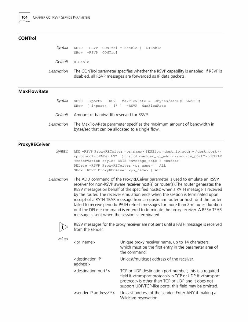
104 CHAPTER 60: RSVP SERVICE PARAMETERS
CONTrol
Syntax SETD -RSVP CONTrol = ENable | DISableSHow -RSVP CONTrol
Default DISable
Description The CONTrol parameter specifies whether the RSVP capability is enabled. If RSVP is disabled, all RSVP messages are forwarded as IP data packets.
MaxFlowRate
Syntax SETD !<port> -RSVP MaxFlowRate = <bytes/sec>(0-562500)SHow [ !<port> | !* ] -RSVP MaxFlowRate
Default Amount of bandwidth reserved for RSVP.
Description The MaxFlowRate parameter specifies the maximum amount of bandwidth in bytes/sec that can be allocated to a single flow.
ProxyRECeiverSyntax: ADD -RSVP ProxyRECeiver <pr_name> SESSion <dest_ip_addr></dest_port*>
<protocol> SENDer ANY | ( list of <sender_ip_addr> </source_port*> ) STYLE<reservation style> RATE <average_rate > <burst>DELete -RSVP ProxyRECeiver <ps_name> | ALLSHow -RSVP ProxyRECeiver <ps_name> | ALL
Description The ADD command of the ProxyRECeiver parameter is used to emulate an RSVP receiver for non-RSVP aware receiver host(s) or router(s).The router generates the RESV messages on behalf of the specified host(s) when a PATH message is received by the router. The receiver emulation ends when the session is terminated upon receipt of a PATH TEAR message from an upstream router or host, or if the router failed to receive periodic PATH refresh messages for more than 2-minutes duration or if the DELete command is entered to terminate the proxy receiver. A RESV TEAR message is sent when the session is terminated.
RESV messages for the proxy receiver are not sent until a PATH message is received from the sender.
Values<pr_name> Unique proxy receiver name, up to 14 characters,
which must be the first entry in the parameter area of the command.
<destination IP address>
Unicast/multicast address of the receiver.
<destination port*> TCP or UDP destination port number; this is a required field if <transport protocol> is TCP or UDP. If <transport protocol> is other than TCP or UDP and it does not support UDP/TCP-like ports, this field may be omitted.
<sender IP address**> Unicast address of the sender. Enter ANY if making a Wildcard reservation.
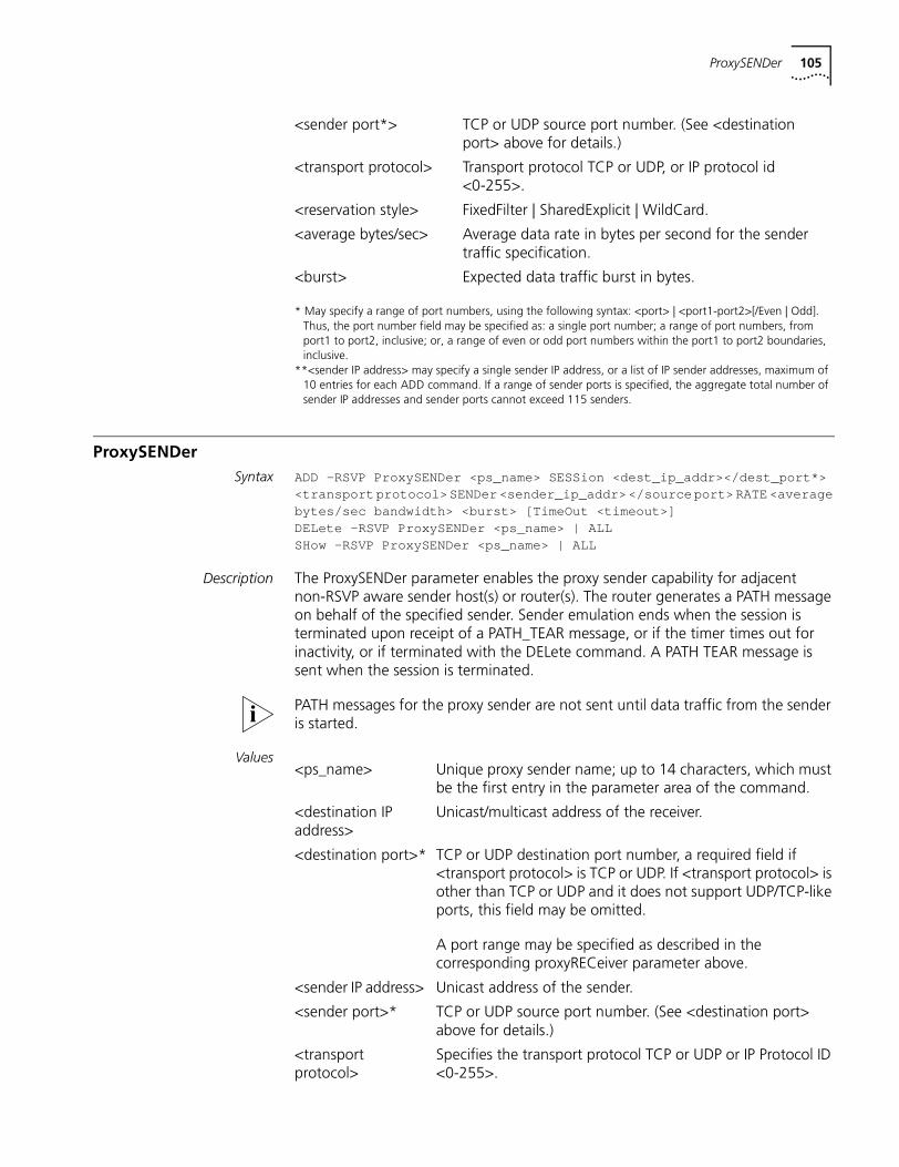
ProxySENDer 105
* May specify a range of port numbers, using the following syntax: <port> | <port1-port2>[/Even | Odd]. Thus, the port number field may be specified as: a single port number; a range of port numbers, from port1 to port2, inclusive; or, a range of even or odd port numbers within the port1 to port2 boundaries, inclusive.
**<sender IP address> may specify a single sender IP address, or a list of IP sender addresses, maximum of 10 entries for each ADD command. If a range of sender ports is specified, the aggregate total number of sender IP addresses and sender ports cannot exceed 115 senders.
ProxySENDerSyntax ADD -RSVP ProxySENDer <ps_name> SESSion <dest_ip_addr></dest_port*>
<transport protocol> SENDer <sender_ip_addr> </source port> RATE <averagebytes/sec bandwidth> <burst> [TimeOut <timeout>]DELete -RSVP ProxySENDer <ps_name> | ALLSHow -RSVP ProxySENDer <ps_name> | ALL
Description The ProxySENDer parameter enables the proxy sender capability for adjacent non-RSVP aware sender host(s) or router(s). The router generates a PATH message on behalf of the specified sender. Sender emulation ends when the session is terminated upon receipt of a PATH_TEAR message, or if the timer times out for inactivity, or if terminated with the DELete command. A PATH TEAR message is sent when the session is terminated.
PATH messages for the proxy sender are not sent until data traffic from the sender is started.
Values
<sender port*> TCP or UDP source port number. (See <destination port> above for details.)
<transport protocol> Transport protocol TCP or UDP, or IP protocol id <0-255>.
<reservation style> FixedFilter | SharedExplicit | WildCard.
<average bytes/sec> Average data rate in bytes per second for the sender traffic specification.
<burst> Expected data traffic burst in bytes.
<ps_name> Unique proxy sender name; up to 14 characters, which must be the first entry in the parameter area of the command.
<destination IP address>
Unicast/multicast address of the receiver.
<destination port>* TCP or UDP destination port number, a required field if <transport protocol> is TCP or UDP. If <transport protocol> is other than TCP or UDP and it does not support UDP/TCP-like ports, this field may be omitted.
A port range may be specified as described in the corresponding proxyRECeiver parameter above.
<sender IP address> Unicast address of the sender.
<sender port>* TCP or UDP source port number. (See <destination port> above for details.)
<transport protocol>
Specifies the transport protocol TCP or UDP or IP Protocol ID <0-255>.
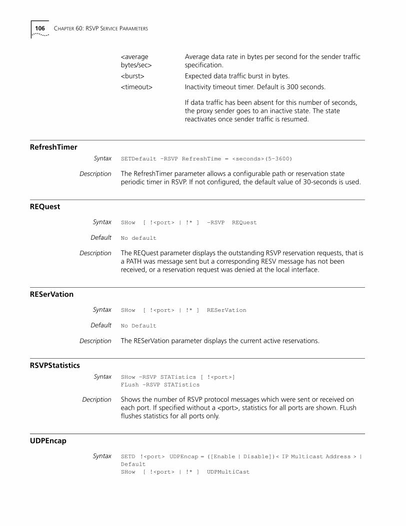
106 CHAPTER 60: RSVP SERVICE PARAMETERS
RefreshTimerSyntax SETDefault -RSVP RefreshTime = <seconds>(5-3600)
Description The RefreshTimer parameter allows a configurable path or reservation state periodic timer in RSVP. If not configured, the default value of 30-seconds is used.
REQuest
Syntax SHow [ !<port> | !* ] -RSVP REQuest
Default No default
Description The REQuest parameter displays the outstanding RSVP reservation requests, that is a PATH was message sent but a corresponding RESV message has not been received, or a reservation request was denied at the local interface.
RESerVation
Syntax SHow [ !<port> | !* ] RESerVation
Default No Default
Description The RESerVation parameter displays the current active reservations.
RSVPStatisticsSyntax SHow -RSVP STATistics [ !<port>]
FLush -RSVP STATistics
Decription Shows the number of RSVP protocol messages which were sent or received on each port. If specified without a <port>, statistics for all ports are shown. FLush flushes statistics for all ports only.
UDPEncap
Syntax SETD !<port> UDPEncap = ([Enable | Disable])< IP Multicast Address > |DefaultSHow [ !<port> | !* ] UDPMultiCast
<average bytes/sec>
Average data rate in bytes per second for the sender traffic specification.
<burst> Expected data traffic burst in bytes.
<timeout> Inactivity timeout timer. Default is 300 seconds.
If data traffic has been absent for this number of seconds, the proxy sender goes to an inactive state. The state reactivates once sender traffic is resumed.
UDPEncap 107
Default Disabled. Only IP-encapsulated RSVP UDPEncap messages are sent unless UDP-only host presence is learned via the receipt of UDP-encapsulated RSVP messages.
Description The UDPEndcap parameter controls the UDP encapsulated RSVP messages. Normally, the NETBuilder bridge/router learns of a UDP host or hosts present at an interface by listening for UDP-encapsulated Path messages that were sent to either the well-known multicast address, 224.0.0.14, or to the address of the interface itself. However, if no UDP-encapsulated path message is received at the interface, the UDPEndcap parameter must be explicitly configured on the interface for the NETBuilder bridge/router to send UDP-encapsulated RSVP messages to a UDP host that is connected at the interface.
If the UDPEndcap parameter is enabled, RSVP messages are sent UDP-encapsulated as well as in raw IP mode at the specified interface. If the UDPEndcap parameter is disabled, RSVP messages are sent in raw IP format only.

108 CHAPTER 60: RSVP SERVICE PARAMETERS
Related Documents