Journal of Mechanical Science and Technology 24 (3) (2010) 681~686 www.springerlink.com/content/1738-494x DOI 10.1007/s12206-010-0114-0 Enhancement of J estimation for typical nuclear pipes with a circumferential surface crack under tensile load Doo Ho Cho 1 , Seung Wan Woo 1 , Yoon-Suk Chang 2 , Jae-Boong Choi 1 , Young-Jin Kim 1,* Myung Jo Jhung 3 and Young Hwan Choi 3 1 School of Mechanical Engineering, Sungkyunkwan Univ., 300 Chunchun-dong, Jangan-gu, Suwon, Kyonggi-do 440-746, Korea 2 Department of Nuclear Engineering, Kyung Hee University, 1 Seocheon-dong, Gilleung, Yongin, Kyonggi, 446-701, Korea 3 Korea Institute of Nuclear Safety 19 Guseong-dong, Yuseong-gu, Daejeon 305-338, Korea (Manuscript received April 15, 2009; revised December 15, 2009; accepted December 15, 2009) ---------------------------------------------------------------------------------------------------------------------------------------------------------------------------------------------------------------------------------------------------------------------------------------------- Abstract This paper is to report enhancement of engineering J estimation for semi-elliptical surface cracks under tensile load. Firstly, limitation of the sole solution suggested by Zahoor is shown for reliable structural integrity assessment of thin-walled nuclear pipes. An improved solution is then developed based on extensive 3D FE analyses employing deformation plasticity theory for typical nuclear piping materi- als. It takes over the structure of the existing solution but provides new tabulated plastic influence functions to cover a wide range of pipe geometry and crack shape. Furthermore, to facilitate easy prediction of the plastic influence function, an alternative simple equation is also developed by using a statistical response surface method. The proposed H 1 values can be used for elastic-plastic fracture analyses of thin-walled pipes with a circumferential surface crack subjected to tensile loading. Keywords: J-integral; Plastic influence function; Response surface method; Stress intensity factor; Thin-walled nuclear pipe ---------------------------------------------------------------------------------------------------------------------------------------------------------------------------------------------------------------------------------------------------------------------------------------------- 1. Introduction Recently, integrity assurance of secondary system compo- nents becomes an important issue relating to impacts on large and early release frequency (LERF) as well as core damage frequency (CDF) due to piping failures in nuclear power plant. The secondary system piping has relatively thin thickness and higher mean radius to thickness ratio (R m /t) of the pipe, as distinguished from primary piping of reactor coolant system, which may cause impossibility for applying well-known elas- tic-plastic J solutions [1-4] basically derived from thick- walled pipes. Battelle Integrity of Nuclear Piping (BINP) project [5] has dealt with the problem as one of several research items. Thereby, a method which is applicable to thin-walled pipes was proposed by adopting a concept of correction coefficient for the existing solutions [2, 3], based on two-dimensional finite element (2D FE) analysis results. Despite its sound re- sults, the BINP method also has some limitations. Although effectiveness of shell and line spring model already has been proven, it is inherently less accurate than 3D FE analysis in use of solid elements. Also, for loading conditions, bending and internal pressure were taken into account but tensile load- ing was not considered. The present research provides an enhanced engineering J estimation for typical nuclear pipes with a circumferential surface crack subject to tensile loading. In this context, the remainder of paper is organized as follows: In section 2, pre- liminary FE analyses are carried out to show limitation of current J estimates. Then, detailed analysis method, extensive 3D elastic-plastic FE models and their results are described in section 3. In section 4, improved J estimates are developed based on Zahoor’s solution with modified plastic influence functions both in tabulated and simple equation forms, which are followed by the last section where conclusions are drawn. 2. Limitation of current J estimates 2.1 R m /t ratio Table 1 shows existing elastic-plastic J solutions for pipe with a circumferential surface crack and it can be pointed out that currently applicable R m /t is equal or less than 20 except for aforementioned BINP method. Also, with regard to tensile load condition, there exists sole solution suggested by Zahoor [6], of which applicability is restricted only to R m /t =10. † This paper was recommended for publication in revised form by Associate Editor Seong Beom Lee * Corresponding author. Tel.: +82 31 290 5274, Fax.: +82 31 290 5276 E-mail address: [email protected] © KSME & Springer 2010

Welcome message from author
This document is posted to help you gain knowledge. Please leave a comment to let me know what you think about it! Share it to your friends and learn new things together.
Transcript

Journal of Mechanical Science and Technology 24 (3) (2010) 681~686
www.springerlink.com/content/1738-494x DOI 10.1007/s12206-010-0114-0
Enhancement of J estimation for typical nuclear pipes with a
circumferential surface crack under tensile load Doo Ho Cho1, Seung Wan Woo1, Yoon-Suk Chang2, Jae-Boong Choi1, Young-Jin Kim1,*
Myung Jo Jhung3 and Young Hwan Choi3 1School of Mechanical Engineering, Sungkyunkwan Univ., 300 Chunchun-dong, Jangan-gu, Suwon, Kyonggi-do 440-746, Korea
2Department of Nuclear Engineering, Kyung Hee University, 1 Seocheon-dong, Gilleung, Yongin, Kyonggi, 446-701, Korea 3Korea Institute of Nuclear Safety 19 Guseong-dong, Yuseong-gu, Daejeon 305-338, Korea
(Manuscript received April 15, 2009; revised December 15, 2009; accepted December 15, 2009)
----------------------------------------------------------------------------------------------------------------------------------------------------------------------------------------------------------------------------------------------------------------------------------------------
Abstract This paper is to report enhancement of engineering J estimation for semi-elliptical surface cracks under tensile load. Firstly, limitation
of the sole solution suggested by Zahoor is shown for reliable structural integrity assessment of thin-walled nuclear pipes. An improved solution is then developed based on extensive 3D FE analyses employing deformation plasticity theory for typical nuclear piping materi-als. It takes over the structure of the existing solution but provides new tabulated plastic influence functions to cover a wide range of pipe geometry and crack shape. Furthermore, to facilitate easy prediction of the plastic influence function, an alternative simple equation is also developed by using a statistical response surface method. The proposed H1 values can be used for elastic-plastic fracture analyses of thin-walled pipes with a circumferential surface crack subjected to tensile loading.
Keywords: J-integral; Plastic influence function; Response surface method; Stress intensity factor; Thin-walled nuclear pipe ---------------------------------------------------------------------------------------------------------------------------------------------------------------------------------------------------------------------------------------------------------------------------------------------- 1. Introduction
Recently, integrity assurance of secondary system compo-nents becomes an important issue relating to impacts on large and early release frequency (LERF) as well as core damage frequency (CDF) due to piping failures in nuclear power plant. The secondary system piping has relatively thin thickness and higher mean radius to thickness ratio (Rm/t) of the pipe, as distinguished from primary piping of reactor coolant system, which may cause impossibility for applying well-known elas-tic-plastic J solutions [1-4] basically derived from thick-walled pipes.
Battelle Integrity of Nuclear Piping (BINP) project [5] has dealt with the problem as one of several research items. Thereby, a method which is applicable to thin-walled pipes was proposed by adopting a concept of correction coefficient for the existing solutions [2, 3], based on two-dimensional finite element (2D FE) analysis results. Despite its sound re-sults, the BINP method also has some limitations. Although effectiveness of shell and line spring model already has been proven, it is inherently less accurate than 3D FE analysis in
use of solid elements. Also, for loading conditions, bending and internal pressure were taken into account but tensile load-ing was not considered.
The present research provides an enhanced engineering J estimation for typical nuclear pipes with a circumferential surface crack subject to tensile loading. In this context, the remainder of paper is organized as follows: In section 2, pre-liminary FE analyses are carried out to show limitation of current J estimates. Then, detailed analysis method, extensive 3D elastic-plastic FE models and their results are described in section 3. In section 4, improved J estimates are developed based on Zahoor’s solution with modified plastic influence functions both in tabulated and simple equation forms, which are followed by the last section where conclusions are drawn.
2. Limitation of current J estimates
2.1 Rm/t ratio
Table 1 shows existing elastic-plastic J solutions for pipe with a circumferential surface crack and it can be pointed out that currently applicable Rm/t is equal or less than 20 except for aforementioned BINP method. Also, with regard to tensile load condition, there exists sole solution suggested by Zahoor [6], of which applicability is restricted only to Rm/t =10.
† This paper was recommended for publication in revised form by Associate EditorSeong Beom Lee
*Corresponding author. Tel.: +82 31 290 5274, Fax.: +82 31 290 5276 E-mail address: [email protected]
© KSME & Springer 2010

682 D. H. Cho et al. / Journal of Mechanical Science and Technology 24 (3) (2010) 681~686
Table 1. Applicable J solutions for pipes with a circumferential surface crack.
Loading type Applicable Rm/t Solution
Tension 10 Zahoor (1990) [6]
5-20 Kim et al. (2002) [7]
7.5 NUREG (1995) [2] Bending
5-60 BINP (2002) [5]
5-20 Kim et al. (2002) [7]
5-15 NUREG (1995) [3] Internal pressure
5-60 BINP (2002) [5]
0 10 20 30 40 50 600
15
30
45
60
Zahoor(a/t=0.25)
Zahoor(a/t=0.50)
H1
Rm/t
FE results, θ/π=0.25 a/t=0.25 a/t=0.50 a/t=0.75
Zahoor(a/t=0.75)
(a) θ/π=0.25
0 10 20 30 40 50 600
20
40
60
80
Zahoor(a/t=0.25)
Zahoor(a/t=0.50)
H1
Rm/t
FE results, θ/π=0.50 a/t=0.25 a/t=0.50 a/t=0.75
Zahoor(a/t=0.75)
(b) θ/π=0.50
Fig. 1. Comparison of H1 values for different pipe geometry and crack shape.
2.2 Preliminary FE analysis
The structure of J solution for tensile loaded thin-walled pipes takes over Zahoor’s one as follows:
FEe pJ J J= + (1)
2 2/(4 )e tJ f P R t Eπ ′= ⋅ ⋅ ⋅ ⋅ ⋅ (2) 1
1 ( / )np o o t oJ t Hα σ ε σ σ += ⋅ ⋅ ⋅ ⋅ ⋅ (3)
where H1 is the plastic influence function dependent upon θ/π, a/t, n and Rm/t.
To confirm limitation of the existing solution, plastic influ-ence functions obtained from preliminary FE analyses and Zahoor’s solution were compared. The FE-based H1 values were determined from Eq. (3), here, the fully plastic part of Jp was obtained by subtracting elastic part of Je from elastic-plastic FE analysis results. As depicted in Fig. 1, first of all,
Table 2. FE analysis matrix.
Rm/t a/t θ /π 5, 10, 15, 20, 25, 30, 35, 40, 45, 50, 55, 60
0.25, 0.50, 0.75
0.25, 0.50
t Ri
Ro
Rm
2θ
a
T
Fig. 2. Schematic illustration of circumferential surface cracked pipe under tensile loading.
FE-based H1 values increased with the increase of Rm/t while Zahoor’s H1 values were constants. Also, H1 values obtained from both methods affected by varying normalized crack depth (a/t) and normalized crack length (θ/π), and effect of a/t was relatively bigger than that of θ/π. In other words, as the increase of a/t, the difference of two types of H1 values was rapidly increased. Additionally, a side observation was taken from these preliminary FE analyses that the maximum differ-ence between two methods was over than two times when Rm/t=5 while its difference was less than 80% at Rm/t=60. Hence, to develop an enhanced J solution, parametric FE analyses are required not only for varying Rm/t but also for diverse a/t and θ/π.
3. Detailed FE analysis
3.1 Geometry and material
Fig. 2 represents the schematic illustration of circumferen-tial surface cracked pipe subjected to tensile load, T. Since three variables such as Rm/t, a/t and θ/π affects to J-integral values as mentioned in the previous section, to cover practical ranges of these variables, seventy-two cases were considered in the present work as summarized in Table 2; twelve values of Rm/t ranging from 5 to 60, three values of a/t ranging from 0.25 to 0.75, and two values of θ/π as 0.25 and 0.50.
Table 3 lists four representative nuclear piping materials taken into account for the FE analyses and their mechanical properties were retrieved from a massive database [8]. All of the materials assumed to follow Ramberg-Osgood (R-O) rela-tionship:
( )n
o o o
ε σ σαε σ σ
= + (4)
where σy denotes the 0.2% proof (yield) stress, εo= σy/E is the reference strain, E is the Young’s modulus, and α and n are the R-O parameters, respectively. Poisson’s ratio is fixed as ν=0.3.
D. H. Cho et al. / Journal of Mechanical Science and Technology 24 (3) (2010) 681~686 683
3.2 Analysis method
A series of detailed FE analyses were performed based on deformation plasticity using the R-O parameters. Materials were modeled to depict isotropic elastic-plastic behaviors that obey J2 flow theory, and a small geometry change continuum FE model was employed. The J-integral values were extracted from general-purpose FE program, ABAQUS [9], using a domain integral technique as a function of the applied tensile load.
3.3 FE model
Fig. 3 depicts a typical 3D FE mesh used in the analysis. Due to symmetry condition, a quarter models was generated by using the reduced integration 20-node bricks (type C3D20R in ABAQUS element library). Especially, the crack tip was designed with focused elements and wedge-shaped elements were used in the crack-tip region as shown in the enlarged area. Confidence of the FE models was obtained by checking the path independence of J values. While the overall deviation of J values calculated from ten contours was lower than a few percents, the J values were finally defined as the mean value of 2nd-8th contours after discarding the closest and furthest ones to the crack front. Further verification of the model was conducted by comparing the FE stress intensity factor (KI) with the corresponding one obtained from existing elastic solution [6] of which applicability is for 5≤Rm/t≤160. In case of FE KI, the J-integral can be easily converted to it by using Eq. (5).
'
I eK E J= (5) where E’=E for plane stress condition and E’=E/ (1-v2) for plane strain condition. Table 3. Mechanical properties of representative nuclear piping materi-als.
Type E (GPa) σy (MPa) α n
SA106 Gr.B 190 222 1.64 4.51
SA106 Gr.C 186 186 1.56 3.75
TP304 186 184 6.68 3.31
TP316 186 168 5.87 3.68
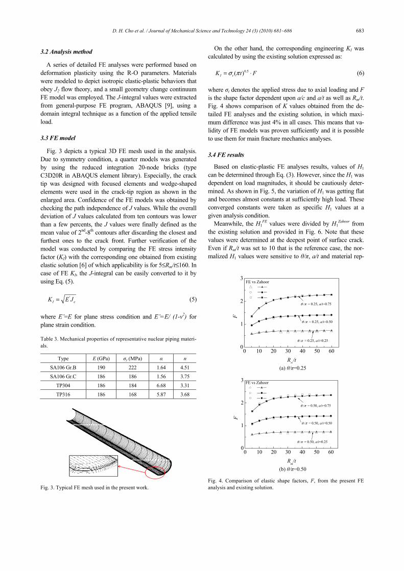
Fig. 3. Typical FE mesh used in the present work.
On the other hand, the corresponding engineering KI was calculated by using the existing solution expressed as:
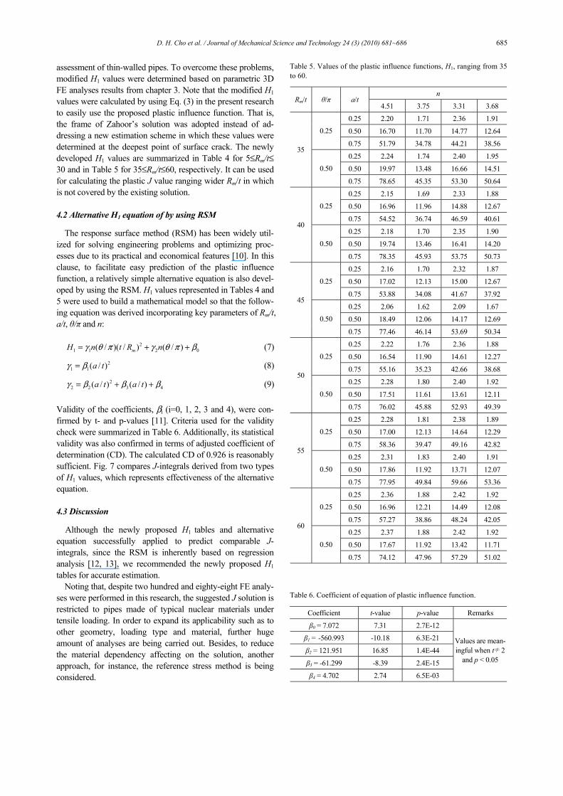
0.5( )I tK t Fσ π= ⋅ (6) where σt denotes the applied stress due to axial loading and F is the shape factor dependent upon a/c and a/t as well as Rm/t. Fig. 4 shows comparison of K values obtained from the de-tailed FE analyses and the existing solution, in which maxi-mum difference was just 4% in all cases. This means that va-lidity of FE models was proven sufficiently and it is possible to use them for main fracture mechanics analyses.
3.4 FE results
Based on elastic-plastic FE analyses results, values of H1 can be determined through Eq. (3). However, since the H1 was dependent on load magnitudes, it should be cautiously deter-mined. As shown in Fig. 5, the variation of H1 was getting flat and becomes almost constants at sufficiently high load. These converged constants were taken as specific H1 values at a given analysis condition.
Meanwhile, the H1FE values were divided by H1
Zahoor from the existing solution and provided in Fig. 6. Note that these values were determined at the deepest point of surface crack. Even if Rm/t was set to 10 that is the reference case, the nor-malized H1 values were sensitive to θ/π, a/t and material rep-
0 10 20 30 40 50 600
1
2
3
θ /π = 0.25, a/t=0.25
θ /π = 0.25, a/t=0.50
θ /π = 0.25, a/t=0.75
F
Rm/t
FE vs Zahoor
(a) θ/π=0.25
0 10 20 30 40 50 600
1
2
3
θ /π = 0.50, a/t=0.25
θ /π = 0.50, a/t=0.50
θ /π = 0.50, a/t=0.75
F
Rm/t
FE vs Zahoor
(b) θ/π=0.50
Fig. 4. Comparison of elastic shape factors, F, from the present FE analysis and existing solution.

684 D. H. Cho et al. / Journal of Mechanical Science and Technology 24 (3) (2010) 681~686
0 1 2 30
5
10
15
20
25
30
Rm/t=10, θ/π=0.50, a/t=0.50
H1FE
σt/σo
SA106B SA106C TP304 TP316
(a) Rm/t=10
0 1 2 30
10
20
30
40
50
Rm/t=60, θ/π=0.50, a/t=0.50
H1FE
σt/σo
SA106B SA106C TP304 TP316
(b) Rm/t=60
Fig. 5. Variation of H1 values according to load levels.
0.00 0.25 0.50 0.75 1.000.5
1.0
1.5Rm/t=10, θ/π=0.25
H1FE
/ H
1zaho
or
a/t
SA106B SA106C TP304 TP316
(a) θ/π=0.25
0.00 0.25 0.50 0.75 1.000.5
1.0
1.5
2.0Rm/t=10, θ/π=0.50
H1F E
/ H
1zaho
or
a/t
SA106B SA106C TP304 TP316
(b) θ/π=0.50
Fig. 6. Normalized H1 values for different a/t when Rm/t=10.
resented by different R-O parameter n, especially for TP304 steel. The normalized H1 values were varied between 0.8 and 1.92. It seems that the deviation of H1
FE and H1Zahoor values
Table 4. Values of the plastic influence functions, H1, ranging from 5 to 30.
n Rm/t θ/π a/t
4.51 3.75 3.31 3.68
0.25 1.42 1.11 1.55 1.25
0.50 5.32 3.96 5.44 4.48 0.25
0.75 16.59 10.89 14.50 12.72
0.25 1.59 1.23 1.68 1.37
0.50 10.07 6.85 9.19 7.97
5
0.50
0.75 55.45 30.66 36.48 34.85
0.25 2.02 1.57 2.13 1.72
0.50 10.75 7.68 10.45 8.81 0.25
0.75 30.39 19.91 25.66 22.36
0.25 2.24 1.71 2.34 1.90
0.50 16.38 10.88 14.18 12.37
10
0.50
0.75 83.03 46.02 53.19 50.21
0.25 2.48 1.89 2.56 2.08
0.50 14.53 10.23 13.54 11.540.25
0.75 43.90 27.63 34.77 30.95
0.25 2.70 2.04 2.77 2.26
0.50 21.86 14.47 18.59 16.2
15
0.50
0.75 69.79 38.95 43.41 41.95
0.25 2.96 2.24 3.01 2.46
0.50 14.69 10.29 13.63 11.630.25
0.75 46.02 29.65 37.78 33.32
0.25 3.20 2.39 3.23 2.65
0.50 18.65 11.40 13.77 12.98
20
0.50
0.75 79.75 47.52 57.57 52.79
0.25 2.28 1.76 2.41 1.96
0.50 14.87 10.39 13.79 11.780.25
0.75 44.69 29.79 38.48 33.51
0.25 2.37 1.81 2.47 2.01
0.50 18.21 11.64 14.16 12.93
25
0.50
0.75 77.63 42.47 49.89 48.85
0.25 2.12 1.65 2.30 1.87
0.50 15.27 10.21 12.66 11.270.25
0.75 46.17 28.33 35.33 32.70
0.25 2.02 1.56 2.06 1.67
0.50 18.76 12.03 14.49 13.18
30
0.50
0.75 78.65 44.21 52.11 50.11
was caused by disparity of FE details or coarse interpolation/ extrapolation processing, which implies necessity for en-hancement of the existing solution.
4. Development of improved J estimates
4.1 New plastic influence function (H1)
As mentioned in chapter 2, the existing solution has limita-tions both in accuracy and usefulness for structural integrity
D. H. Cho et al. / Journal of Mechanical Science and Technology 24 (3) (2010) 681~686 685
assessment of thin-walled pipes. To overcome these problems, modified H1 values were determined based on parametric 3D FE analyses results from chapter 3. Note that the modified H1 values were calculated by using Eq. (3) in the present research to easily use the proposed plastic influence function. That is, the frame of Zahoor’s solution was adopted instead of ad-dressing a new estimation scheme in which these values were determined at the deepest point of surface crack. The newly developed H1 values are summarized in Table 4 for 5≤Rm/t≤ 30 and in Table 5 for 35≤Rm/t≤60, respectively. It can be used for calculating the plastic J value ranging wider Rm/t in which is not covered by the existing solution.
4.2 Alternative H1 equation of by using RSM
The response surface method (RSM) has been widely util-ized for solving engineering problems and optimizing proc-esses due to its practical and economical features [10]. In this clause, to facilitate easy prediction of the plastic influence function, a relatively simple alternative equation is also devel-oped by using the RSM. H1 values represented in Tables 4 and 5 were used to build a mathematical model so that the follow-ing equation was derived incorporating key parameters of Rm/t, a/t, θ/π and n:
2
1 1 2 0( / )( / ) ( / )mH n t R nγ θ π γ θ π β= + + (7)
21 1( / )a tγ β= (8)
22 2 3 4( / ) ( / )a t a tγ β β β= + + (9)
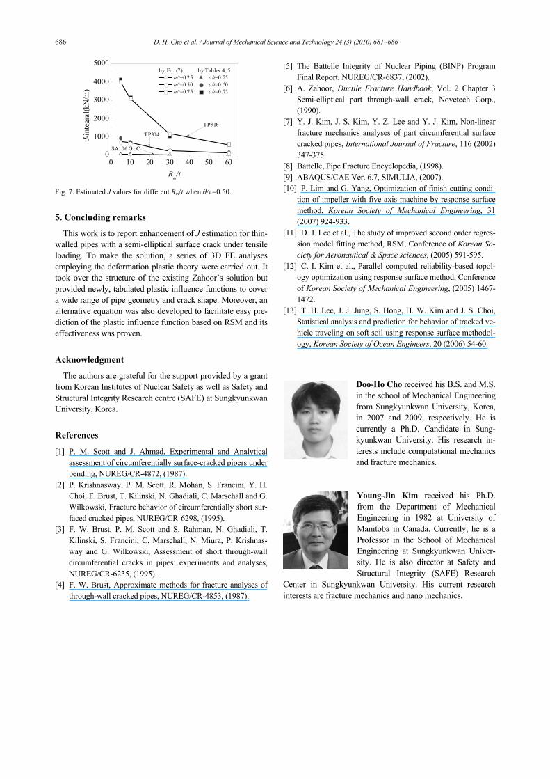
Validity of the coefficients, βi (i=0, 1, 2, 3 and 4), were con-firmed by t- and p-values [11]. Criteria used for the validity check were summarized in Table 6. Additionally, its statistical validity was also confirmed in terms of adjusted coefficient of determination (CD). The calculated CD of 0.926 is reasonably sufficient. Fig. 7 compares J-integrals derived from two types of H1 values, which represents effectiveness of the alternative equation.
4.3 Discussion
Although the newly proposed H1 tables and alternative equation successfully applied to predict comparable J-integrals, since the RSM is inherently based on regression analysis [12, 13], we recommended the newly proposed H1
tables for accurate estimation. Noting that, despite two hundred and eighty-eight FE analy-
ses were performed in this research, the suggested J solution is restricted to pipes made of typical nuclear materials under tensile loading. In order to expand its applicability such as to other geometry, loading type and material, further huge amount of analyses are being carried out. Besides, to reduce the material dependency affecting on the solution, another approach, for instance, the reference stress method is being considered.
Table 5. Values of the plastic influence functions, H1, ranging from 35 to 60.
n Rm/t θ/π a/t
4.51 3.75 3.31 3.68
0.25 2.20 1.71 2.36 1.91
0.50 16.70 11.70 14.77 12.640.25
0.75 51.79 34.78 44.21 38.56
0.25 2.24 1.74 2.40 1.95
0.50 19.97 13.48 16.66 14.51
35
0.50
0.75 78.65 45.35 53.30 50.64
0.25 2.15 1.69 2.33 1.88
0.50 16.96 11.96 14.88 12.670.25
0.75 54.52 36.74 46.59 40.61
0.25 2.18 1.70 2.35 1.90
0.50 19.74 13.46 16.41 14.20
40
0.50
0.75 78.35 45.93 53.75 50.73
0.25 2.16 1.70 2.32 1.87
0.50 17.02 12.13 15.00 12.670.25
0.75 53.88 34.08 41.67 37.92
0.25 2.06 1.62 2.09 1.67
0.50 18.49 12.06 14.17 12.69
45
0.50
0.75 77.46 46.14 53.69 50.34
0.25 2.22 1.76 2.36 1.88
0.50 16.54 11.90 14.61 12.270.25
0.75 55.16 35.23 42.66 38.68
0.25 2.28 1.80 2.40 1.92
0.50 17.51 11.61 13.61 12.11
50
0.50
0.75 76.02 45.88 52.93 49.39
0.25 2.28 1.81 2.38 1.89
0.50 17.00 12.13 14.64 12.290.25
0.75 58.36 39.47 49.16 42.82
0.25 2.31 1.83 2.40 1.91
0.50 17.86 11.92 13.71 12.07
55
0.50
0.75 77.95 49.84 59.66 53.36
0.25 2.36 1.88 2.42 1.92
0.50 16.96 12.21 14.49 12.080.25
0.75 57.27 38.86 48.24 42.05
0.25 2.37 1.88 2.42 1.92
0.50 17.67 11.92 13.42 11.71
60
0.50
0.75 74.12 47.96 57.29 51.02 Table 6. Coefficient of equation of plastic influence function.
Coefficient t-value p-value Remarks
β0 = 7.072 7.31 2.7E-12
β1 = -560.993 -10.18 6.3E-21
β2 = 121.951 16.85 1.4E-44
β3 = -61.299 -8.39 2.4E-15
β4 = 4.702 2.74 6.5E-03
Values are mean-ingful when t≠2
and p < 0.05
686 D. H. Cho et al. / Journal of Mechanical Science and Technology 24 (3) (2010) 681~686
0 10 20 30 40 50 600
1000
2000
3000
4000
5000
SA106 Gr.C
TP304J-in
tegr
al(k
N/m
)
Rm/t
by Eq. (7) by Tables 4, 5 a/t=0.25 a/t=0.25 a/t=0.50 a/t=0.50 a/t=0.75 a/t=0.75
TP316
Fig. 7. Estimated J values for different Rm/t when θ/π=0.50.
5. Concluding remarks
This work is to report enhancement of J estimation for thin-walled pipes with a semi-elliptical surface crack under tensile loading. To make the solution, a series of 3D FE analyses employing the deformation plastic theory were carried out. It took over the structure of the existing Zahoor’s solution but provided newly, tabulated plastic influence functions to cover a wide range of pipe geometry and crack shape. Moreover, an alternative equation was also developed to facilitate easy pre-diction of the plastic influence function based on RSM and its effectiveness was proven.
Acknowledgment
The authors are grateful for the support provided by a grant from Korean Institutes of Nuclear Safety as well as Safety and Structural Integrity Research centre (SAFE) at Sungkyunkwan University, Korea.
References
[1] P. M. Scott and J. Ahmad, Experimental and Analytical assessment of circumferentially surface-cracked pipers under bending, NUREG/CR-4872, (1987).
[2] P. Krishnasway, P. M. Scott, R. Mohan, S. Francini, Y. H. Choi, F. Brust, T. Kilinski, N. Ghadiali, C. Marschall and G. Wilkowski, Fracture behavior of circumferentially short sur-faced cracked pipes, NUREG/CR-6298, (1995).
[3] F. W. Brust, P. M. Scott and S. Rahman, N. Ghadiali, T. Kilinski, S. Francini, C. Marschall, N. Miura, P. Krishnas-way and G. Wilkowski, Assessment of short through-wall circumferential cracks in pipes: experiments and analyses, NUREG/CR-6235, (1995).
[4] F. W. Brust, Approximate methods for fracture analyses of through-wall cracked pipes, NUREG/CR-4853, (1987).
[5] The Battelle Integrity of Nuclear Piping (BINP) Program Final Report, NUREG/CR-6837, (2002).
[6] A. Zahoor, Ductile Fracture Handbook, Vol. 2 Chapter 3 Semi-elliptical part through-wall crack, Novetech Corp., (1990).
[7] Y. J. Kim, J. S. Kim, Y. Z. Lee and Y. J. Kim, Non-linear fracture mechanics analyses of part circumferential surface cracked pipes, International Journal of Fracture, 116 (2002) 347-375.
[8] Battelle, Pipe Fracture Encyclopedia, (1998). [9] ABAQUS/CAE Ver. 6.7, SIMULIA, (2007). [10] P. Lim and G. Yang, Optimization of finish cutting condi-
tion of impeller with five-axis machine by response surface method, Korean Society of Mechanical Engineering, 31 (2007) 924-933.
[11] D. J. Lee et al., The study of improved second order regres-sion model fitting method, RSM, Conference of Korean So-ciety for Aeronautical & Space sciences, (2005) 591-595.
[12] C. I. Kim et al., Parallel computed reliability-based topol-ogy optimization using response surface method, Conference of Korean Society of Mechanical Engineering, (2005) 1467-1472.
[13] T. H. Lee, J. J. Jung, S. Hong, H. W. Kim and J. S. Choi, Statistical analysis and prediction for behavior of tracked ve-hicle traveling on soft soil using response surface methodol-ogy, Korean Society of Ocean Engineers, 20 (2006) 54-60.
Doo-Ho Cho received his B.S. and M.S. in the school of Mechanical Engineering from Sungkyunkwan University, Korea, in 2007 and 2009, respectively. He is currently a Ph.D. Candidate in Sung-kyunkwan University. His research in-terests include computational mechanics and fracture mechanics.
Young-Jin Kim received his Ph.D. from the Department of Mechanical Engineering in 1982 at University of Manitoba in Canada. Currently, he is a Professor in the School of Mechanical Engineering at Sungkyunkwan Univer-sity. He is also director at Safety and Structural Integrity (SAFE) Research
Center in Sungkyunkwan University. His current research interests are fracture mechanics and nano mechanics.
Related Documents