No number Enhancement of Automotive Penetration Testing with Threat Analyses Results Jürgen Dürrwang 1 , Johannes Braun 1 , Marcel Rumez 1 , Reiner Kriesten 1 and Alexander Pretschner 2 Institute of Energy Efcient Mobility (IEEM) 1 , Karlsruhe University of Applied Sciences, International University Campus 3, 76646 Bruchsal, Germany Software Engineering 2 , Technical University of Munich (TUM), Boltzmannstr. 3, 85748 Garching, Germany Copyright c 2018 Society of Automotive Engineers, Inc. ABSTRACT In this work, we present an approach to support penetration tests by combining safety and security analyses to enhance automotive security testing. Our approach includes a new way to combine safety and threat analyses to derive possible test cases. We reuse outcomes of a performed safety analysis as the input for a threat analysis. We show systematically how to derive test cases and we present the applicability of our approach by deriving and performing test cases for a penetration test of an automotive Electronic Control Unit (ECU). Therefore, we selected an airbag control unit due to its safety-critical functionality. During the penetration test, the selected control unit was installed on a test bench and we were able to successfully exploit a discovered vulnerability, causing the detonation of airbags. INTRODUCTION Modern automobiles host more than 50 ECUs, which contain a total of up to 100 million code lines to control safety-critical functionality [1]. In total, this fact and the close interconnectivity of automotive ECUs open up new possibilities to attack these systems. Many of these attacks affect the safe operation of the vehicle which can lead to injuries of the passengers [2][3][4][5]. To decrease the possibility of such scenarios, security has to be an integral part of the development lifecycle. In order to achieve the highest level of protection against security attacks, the Security by Design concept represents a promising attempt. Therefore, security tasks have to be embedded in early phases of the development lifecycle. One security- related task is the Threat Analysis and Risk Assessment (TARA). It identies and prioritizes possible threats against the target which can lead to security incidents. Thus, countermeasures or design changes can be applied before the rst line of code is written. In contrast, a validation of implemented security measures and a review of further vulnerabilities after an implementation should be performed. This can be done with a security testing of the system including internal and/or external testing. In particular, internal security testing is typically executed during the product development. On the other hand, external security tests, which are usually performed after product development, are called penetration tests if they are performed from the perspective of an attacker (see Figure 1, right path). Figure 1: Classication of security testing and the supposed knowledge level Internal security testing corresponds to a white-box approach having a great amount of information, e.g. development documents, source code, etc. Therefore, this testing scenario is best suited for validating of implemented security measures. To determine the resistance level of a system against hackers, penetration testing is the way 1

Welcome message from author
This document is posted to help you gain knowledge. Please leave a comment to let me know what you think about it! Share it to your friends and learn new things together.
Transcript
No number
Enhancement of Automotive Penetration Testingwith Threat Analyses Results
Jürgen Dürrwang1, Johannes Braun1, Marcel Rumez1, Reiner Kriesten1 and Alexander Pretschner2
Institute of Energy Efficient Mobility (IEEM)1, Karlsruhe University of Applied Sciences,International University Campus 3, 76646 Bruchsal, Germany
Software Engineering2, Technical University of Munich (TUM),Boltzmannstr. 3, 85748 Garching, Germany
Copyright c© 2018 Society of Automotive Engineers, Inc.
ABSTRACT
In this work, we present an approach to support penetrationtests by combining safety and security analyses to enhanceautomotive security testing. Our approach includes anew way to combine safety and threat analyses to derivepossible test cases. We reuse outcomes of a performedsafety analysis as the input for a threat analysis. We showsystematically how to derive test cases and we present theapplicability of our approach by deriving and performingtest cases for a penetration test of an automotive ElectronicControl Unit (ECU). Therefore, we selected an airbagcontrol unit due to its safety-critical functionality. Duringthe penetration test, the selected control unit was installedon a test bench and we were able to successfully exploit adiscovered vulnerability, causing the detonation of airbags.
INTRODUCTION
Modern automobiles host more than 50 ECUs, whichcontain a total of up to 100 million code lines to controlsafety-critical functionality [1]. In total, this fact and theclose interconnectivity of automotive ECUs open up newpossibilities to attack these systems. Many of these attacksaffect the safe operation of the vehicle which can lead toinjuries of the passengers [2][3][4][5]. To decrease thepossibility of such scenarios, security has to be an integralpart of the development lifecycle. In order to achievethe highest level of protection against security attacks,the Security by Design concept represents a promisingattempt. Therefore, security tasks have to be embeddedin early phases of the development lifecycle. One security-related task is the Threat Analysis and Risk Assessment(TARA). It identifies and prioritizes possible threats
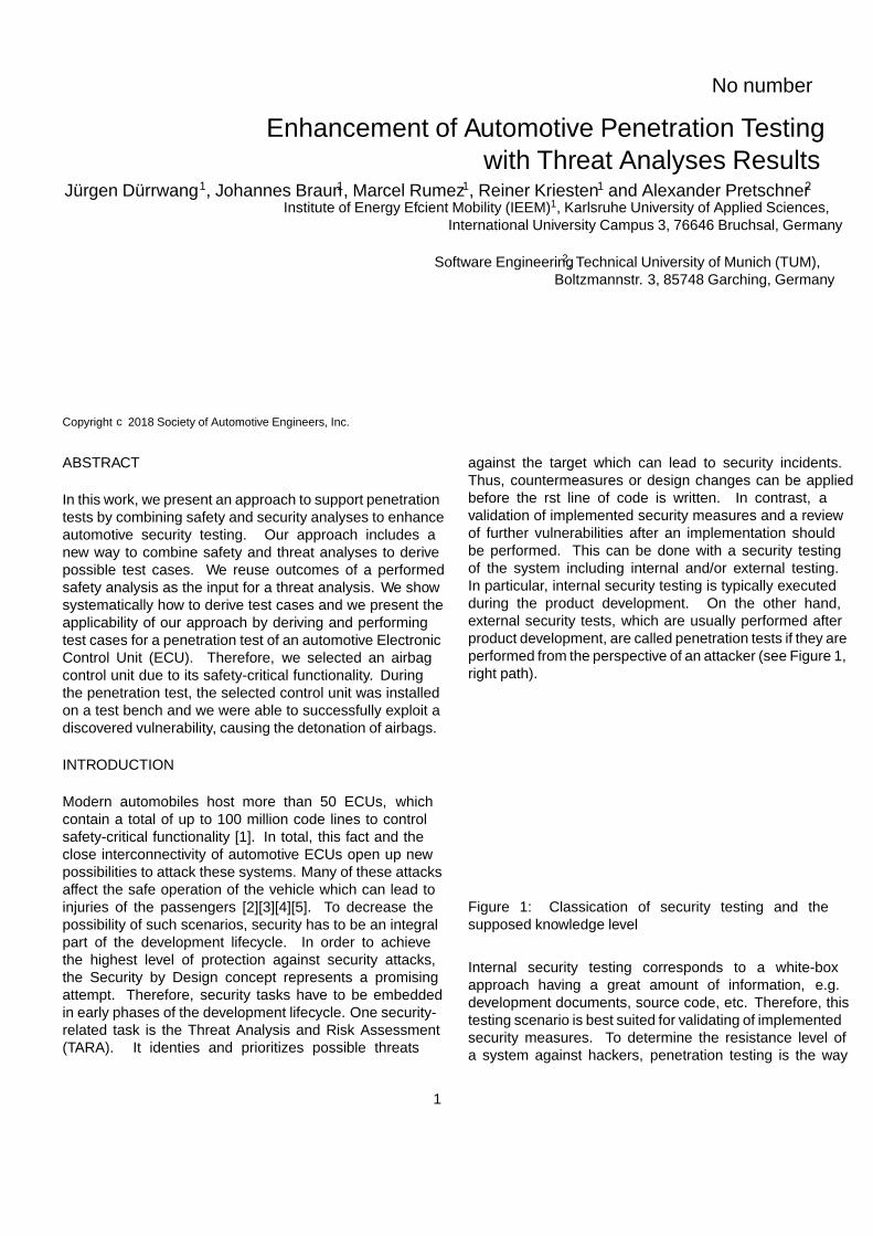
against the target which can lead to security incidents.Thus, countermeasures or design changes can be appliedbefore the first line of code is written. In contrast, avalidation of implemented security measures and a reviewof further vulnerabilities after an implementation shouldbe performed. This can be done with a security testingof the system including internal and/or external testing.In particular, internal security testing is typically executedduring the product development. On the other hand,external security tests, which are usually performed afterproduct development, are called penetration tests if they areperformed from the perspective of an attacker (see Figure 1,right path).
Security testing
Internal security testing External security testing
Black-box approachWhite-box approach
typically
performed by
typically
performed by
Figure 1: Classification of security testing and thesupposed knowledge level
Internal security testing corresponds to a white-boxapproach having a great amount of information, e.g.development documents, source code, etc. Therefore, thistesting scenario is best suited for validating of implementedsecurity measures. To determine the resistance level ofa system against hackers, penetration testing is the way
1
to go [6]. Unfortunately, setting up a penetration test isnot an easy task. Especially, if less knowledge of thedevice under test is available. Due to the fact that thetester has no detailed knowledge of the implementation butonly a functional description of the system, the test can bedescribed as a black-box test [7]. Hence, we consider it asreasonable to reuse the results of a threat modeling processto reduce the effort for security testing.
As safety violations can also be caused by securityproblems, it is important to analyse Hazard Analysis andRisk Assessment (HARA) results in terms of security.Beyond that, safety analyses performed with HARAsare a fixed part in the automotive sector. Results ofthese analyses contain valuable knowledge which can beused for threat modeling and therefore for penetrationtesting as well. Unfortunately, no approach exists whichreuses HARA and TARA results for penetration testing.Consequently, we want to show the first step towardsan approach that reuses results of both analysis typesfor decreasing the security testing effort. Moreover, weevaluate our approach by applying it for a safety criticalECU. In detail, the contributions of this paper are thefollowing:
Problem: As penetration tests are mainly driven by tester-experience, an integration of threat analyses may increasethe testing quality due to a complementary concept for testcase generation.Solution: We provide a methodology for test casegeneration with an adapted threat and risk analysis. To bemore specific, we show the necessary steps for generatingtest cases using attack trees and how we embed these stepsin a well-known security testing methodology. To do this,we transform identified threats into attack trees and derivetest cases from each tree branch.Contribution: Besides the derivation of test cases usingattack trees, we also show how the results of a safetyanalysis can be reused. This will be done by thecombination of a given Hazard analysis with a Threatand Risk analysis. In particular, we show how identifiedhazards can be used to identify threats that couldcompromise vehicle safety. In addition, we evaluated ourmethodology steps with a penetration test of an Airbag-ECU. As a result of our research, we have discovereda vulnerability that can cause life-threatening injuries tovehicle occupants and appears to exist across severalmanufacturers.
The paper is structured as follows: In theSection Background, we give a short overview of securitytesting concepts used in Information Technology (IT) andtheir suitability for the automotive domain. Furthermore,we summarize threat analysis methodologies which areknown to be applicable for automotive systems. In theSection Approach, we show how to integrate threatmodeling results for security testing. To show the practical
applicability of our approach we provide an example inthe Section Experimental Evaluation. Additionally,we suggest possible countermeasures to mitigate thediscovered vulnerability, and conclude with an outlook inthe Section Conclusion and Future Work.
BACKGROUND
SECURITY TESTING METHODOLOGIES Atraditional approach in IT to assess the security of asystem is the application of a penetration test. In thistype of testing, the security engineers do not have anydetailed information about the target system. The objectiveof penetration testing is to analyse the security levelof a system, network or application from an attacker’sperspective. This also implicates to use general publictools and methods which are available to a potentialhacker. The primary goal of penetration testing is tofind vulnerabilities that are not found during internalsecurity testing and could be exploited by an adversary.Furthermore, penetration testing is usually a mandatorypart of a security testing. The execution of penetrationtests is normally at a late stage of the product developmentor afterwards. If any security issues are uncovered at thispoint, the costs and efforts of software patches are high incontrast to early development stages. Thus, a combinationof white-box testing during the product development andpenetration testing after the product release is reasonable.
For clarification, in this paper we don’t want to proposea completely new penetration testing methodology, butrather an approach to identify feasible test cases forpenetration testing by using threat modeling techniques.Therefore, we have analysed publicly available securitytesting methodologies, which are commonly applied in thetraditional IT. In contrast, there are still no guidelinesexplicitly for the automotive sector. The Open SourceSecurity Testing Methodology Manual (OSSTMM) [8]includes fundamentals in security risks, metrics, anddisclosure as well as planning and execution of differenttest types. However, there is no part with detailedinformation with a focus on penetration testing. Thespecial publication 800-115 of National Institute ofStandards and Technology (NIST) [9] gives a goodoverview and practical recommendations for securitytesting similar to OSSTMM without the intention torepresent a comprehensive security testing guideline.In contrast to OSSTMM, the Information SystemsSecurity Assessment Framework (ISSAF) [10] is verycomprehensive and presents strategies, assessments, andcheck-lists. Beyond that, ISSAF includes also a penetrationtesting methodology and defines different steps forperforming these type of test but does not integrate athreat analysis in its steps. In addition, the structure asa framework allows an integration in the business lifecycle [11]. Furthermore, the Penetration Testing Execution
2
Standard (PTES) [12] is a technical guideline exclusivelyfor penetration testing. Similar to ISSAF, it containsdifferent steps to perform a comprehensive test procedureand explains each step in detail with recommendations,which software tools can be used. Furthermore, the PTESrecommends to perform a threat modeling step as the onlymethod. Unfortunately, the standard does not suggest aspecific model but rather which consistent terms should besupported by the used model. The guideline presented bythe Open Web Application Security Project (OWASP) [13]can be seen as a special field for testing the security of webapplications.
In summary, the analysed security testing methodologieshave different characteristics relating to penetration testing.Only the PTES guideline supports the approach of threatmodeling, which is fundamental part of our approach toderive test cases. As we mentioned before, PTES doesnot recommend a specific methodology for this step. Forthis reason, we depict differences between existing threatmodeling methodologies in the next section relating totheir applicability for Cyber-Physical-Systems (CPS) dueto their special relationship between safety and security.
THREAT MODELING The concept of threat modelingis an integral part of our overall methodology andtherefore we will briefly describe the existing methodsfor threat modeling of automotive systems in thefollowing. We want to start with approaches explicitlyrecommended for the automotive sector and listed bySAE in its Cybersecurity Guidebook for Cyber-PhysicalVehicle Systems (SAE J3061 [14]). The guidebooksuggests to apply the Operationally Critical Threat, Asset,and Vulnerability Evaluation (OCTAVE) approach, theHEAling Vulnerabilities to ENhance Software Security andSafety (HEAVENS) [15] methodology, and the E-SafetyVehicle Intrusion Protected Applications (EVITA) [16][17]approach. OCTAVE was developed for enterprise securityrisk assessment. Therefore, it does not directly addressspecific attributes of automotive systems which makesit less meaningful to apply in the automotive domain.The HEAVENS methodology is focused on threats of theMicrosoft Spoofing, Tampering, Repudiation, Informationdisclosure, Denial of service, Elevation of privilege(STRIDE) classification model [18][19]. Due to the factthat the scope of STRIDE is mainly on security goals,it depends on the security engineer to decide whether athreat violates the safety of a vehicle or not. This factimplies that security engineers have to be familiar withsafety to decide if a threat can violate a safety goal. Lastly,EVITA uses dark-side scenarios as unintended use casesto identify possible security threats. The methodology ismainly focused on vehicle-to-vehicle connections and lesson in-vehicular networks. The threat identification dependshighly on the set of use cases (dark-side scenarios) whereassafety-related use cases are less in focus. As a result,
threats with impact on safety can be unconsidered by usingthis approach. Furthermore, the classification of safety andnon-safety threats is different. Hence, this can lead to anunbalanced threat assessment [20].
Besides the listed threat modeling methodologies in theSociety of Automotive Engineers (SAE) guidebook, wewant to mention the Hybrid Threat Modeling Method(hTMM) approach developed by a CERT division [21].The approach combines Security Cards [22] and thepersona non grata (PnG) for threat and risk identification.Especially, the provision of so-called Security Cards toguide the analyst through the brainstorming phase shouldbe mentioned. Besides its benefit to support the analystin the brainstorming phase, the approach does not directlyfocus on identification of threats that can violate the safetyof the item under analysis. In conclusion, the approach isnot developed to import results of a pre-performed safetyanalysis.
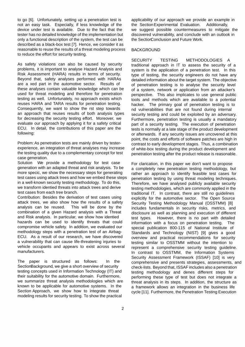
Threat Modeling Including Safety We were particularlyinterested in identifying test cases that can violate thesafety of the vehicle. Therefore, a threat modelingmethodology should be able to identify this particularthreat type. To obtain a considerable number of candidatesfor such threat modeling methodologies, we conducted aliterature survey and identified additional threat analysismethodologies which were not explicitly mentioned inthe SAE guidebook. In particular, we additionally foundthe Security-aware Hazard and Risk Analysis Method(SAHARA) [23][24] and the Failure Mode Vulnerabilitiesand Effect Analysis (FMVEA) [25][26]. We decidedto assign the identified methodologies to the classesof safety and security depending on their focus andaccording to our point of view. The resulting classificationcontains exclusive methods for HARA and TARA aswell as a categorization for combined methodologies likeHEAVENS or CORAS [27] shown in Figure 2.
HARA TARA
Safety Security
OCTAVE, STRIDE, hTMM
HEAVENS, EVITA, SAHARA, FMVEA,...HAZOP, FMEA,
FTA,...
CORAS, STPA-SafeSec, SGM
Figure 2: Classification of HARA and TARA methodswhich were selected from the literature survey
3
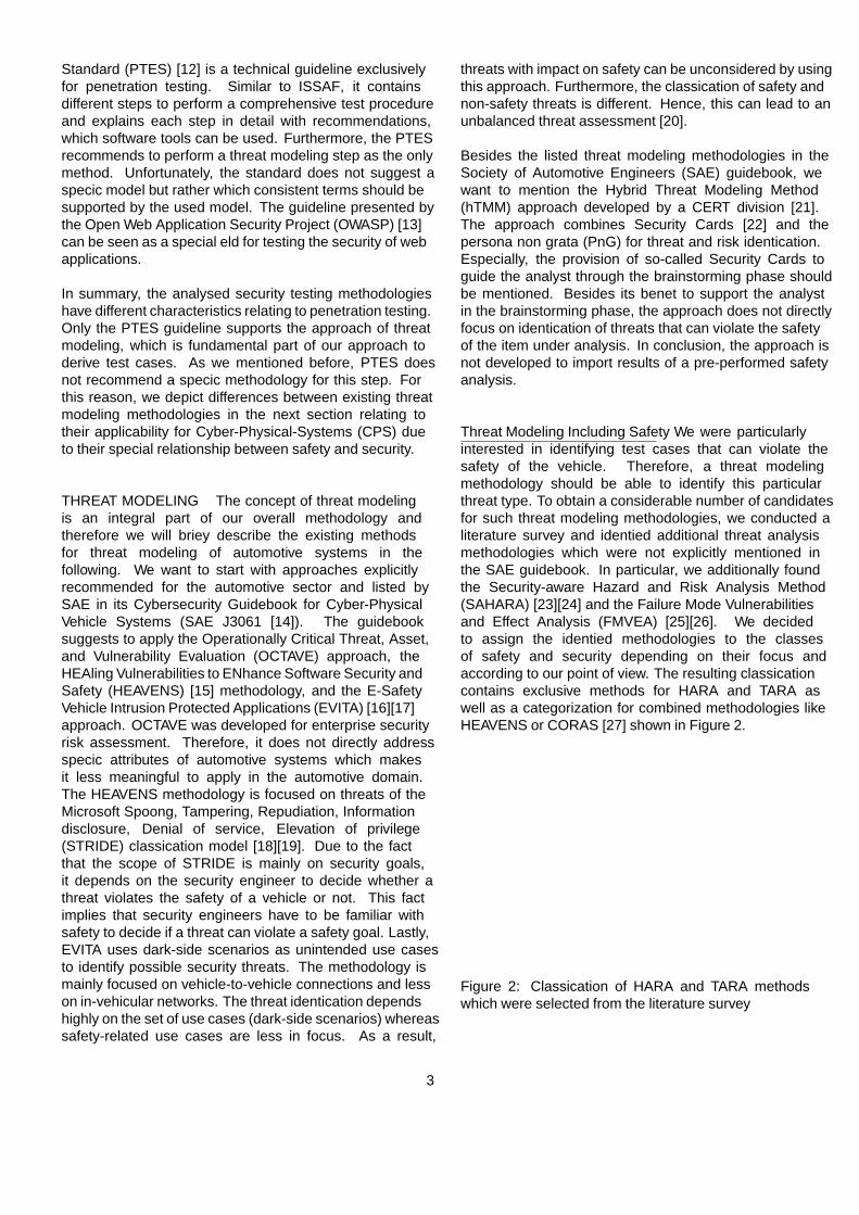
Table 1: Threat analysis methodologies with regard to safety, mentioned in the automotive context
Criteria SAHARA FMVEA EVITA HEAVENSScope ofapplication
Automotive systems Cyber-Physical-Systems(CPS)
Automotive systems Automotive systems
Threat modelingapproach
STRIDE STRIDE Dark-side scenarioswith attack trees
STRIDE
Type of safety &security linking
Hazards and threats areidentified and securitythreats with safetyconsequences are passed onto safety analysts.
Failure modes and threatsare detected in parallelwithout any exchangebetween the both domains.
Only risk assessmentof threats in terms ofsafety.
Only risk assessmentof threats in terms ofsafety.
HARA is a subset in the safety set shown in Figure 2illustrating methods which are exclusively used for safetyanalyses. In particular, these are the Hazard andOperability Study (HAZOP), the Failure Mode and EffectsAnalysis (FMEA) or the Fault Tree Analysis (FTA). On theother hand, TARA methods are a subset of the security set.We made a distinction between threat modeling methodsthat do not address safety (OCTAVE, STRIDE and hTMM)and methodologies that address safety in specific parts,e.g. determining severity values for threats violating safety.These are in particular: HEAVENS, EVITA, SAHARAand FMVEA. Besides the distinction, if a proposed threatmodeling methodology addresses safety, it was of interestat which point this is done. Therefore, we evaluated thethreat modeling methodologies listed in Figure 2 with thecriteria in Table 1. It was interesting to know, on whichdomain the proposed methods are focussed, the techniquefor identifying threats and especially if the methodologyprovides a link between safety and security.
Our analysis has shown that EVITA and HEAVENS onlyaddress safety after security threats have been identified.This is done by a safety risk value if the threat influencessafety. This means that these methodologies do notexplicitly focus on the threat identification regardingsafety. Furthermore, both methodologies do not integrateor claim a safety analysis in their description. However,SAHARA and FMVEA have a stronger focus on safety.Both methodologies determine risk values for securitythreats which have a safety impact. Besides this, SAHARAclaims to perform a HARA as well as a TARA in a parallelmanner. In addition, the methodology examines if theidentified threats can violate the safety of the vehicle andforwards identified threats to safety analysts who rate thesafety impact [24]. Unfortunately, neither SAHARA norFMVEA reuse identified failures or hazards of a safetyanalysis as an input for their threat analysis. This impliesthat the outcomes of a performed safety analysis are notused for threat identification. Thus, it depends on thesecurity engineer to decide if a threat is safety-criticalor not. As a result, security engineers must have safetyknowledge.
Methodologies from other domains like Information andCommunication Technology (ICT) provide the capabilityto reuse results of a perform safety analysis. A holisticoverview of such approaches is given by the researchersFriedberg et al. [28]. They provide a survey of researchpapers for combined safety and security analyses whichcan be selected for CPSs. Friedberg et al. list differentapproaches classified in two categories: generic andmodel-based approaches. The latter are subdivided intographical and non-graphical approaches. As part of theevaluated methods we want to mention the CORAS [27]approach and STPA-sec [29] with the extension STPA-SafeSec [30]. These methodologies suggest performinga hazard analysis followed by a security threat analysis.This makes it possible to include and reuse resultsof safety analyses. Furthermore, the methods can beapplied in an early development phase which offersadvantages for early design decisions. For the analysis,CORAS uses UML models and STPA-SafeSec use controlloops with component layer diagrams to identify securityconstraints [30]. Both approaches meet most of ourdemands for a combined safety and security method.But they are rather complex and not easy to integrateinto existent safety analyses due to the fact that theyrequire specific method steps. As a result, we decided touse another approach for a combined safety and securityanalysis that can be easily integrated into existing safetyanalyses while also achieving a link between safety andsecurity. The method is called Security Guide-wordMethod (SGM) and will be described in the next section.
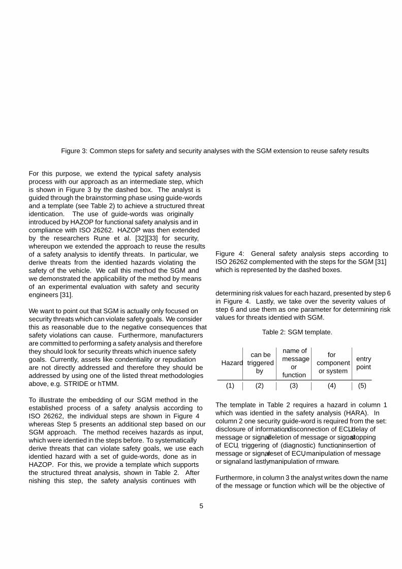
Threat Modeling Using the Security Guide-word MethodIn this section, we give an overview of our previouspresented approach [31] for combining safety and securityanalyses by reason of reusing this method as a componentfor our security testing approach. The approach reusesidentified hazards as an input for the threat analysiswithout changing the typical safety analysis steps (seeFigure 4) and can be easily integrated into establishedsafety and security processes presented in Figure 3. Werecommend our method to safety engineers as it enablesthem to identify threats that can impair vehicle safety.
4
Definition of
analysis scope
Hazard identification
(e.g. HAZOP, FMEA,...)
Identification of threats that
can violate safety goals
(SGM)
Risk assessment
Definition of
analysis scope
Identification of assets
(e.g. use cases,
brainstorming,...)
Identification of threats
(e.g. ATA, DFD & STRIDE, ...)Risk assessment
Safety teamSafety team
Security teamSecurity team
Hazard Analysis and Risk
Assessment (HARA)
Threat Analysis and Risk
Assessment (TARA)
Identified
threats
Severity value
of identified
threats
Conventional way
Proposed extension
Figure 3: Common steps for safety and security analyses with the SGM extension to reuse safety results
For this purpose, we extend the typical safety analysisprocess with our approach as an intermediate step, whichis shown in Figure 3 by the dashed box. The analyst isguided through the brainstorming phase using guide-wordsand a template (see Table 2) to achieve a structured threatidentification. The use of guide-words was originallyintroduced by HAZOP for functional safety analysis and incompliance with ISO 26262. HAZOP was then extendedby the researchers Rune et al. [32][33] for security,whereupon we extended the approach to reuse the resultsof a safety analysis to identify threats. In particular, wederive threats from the identified hazards violating thesafety of the vehicle. We call this method the SGM andwe demonstrated the applicability of the method by meansof an experimental evaluation with safety and securityengineers [31].
We want to point out that SGM is actually only focused onsecurity threats which can violate safety goals. We considerthis as reasonable due to the negative consequences thatsafety violations can cause. Furthermore, manufacturersare committed to performing a safety analysis and thereforethey should look for security threats which influence safetygoals. Currently, assets like confidentiality or repudiationare not directly addressed and therefore they should beaddressed by using one of the listed threat methodologiesabove, e.g. STRIDE or hTMM.
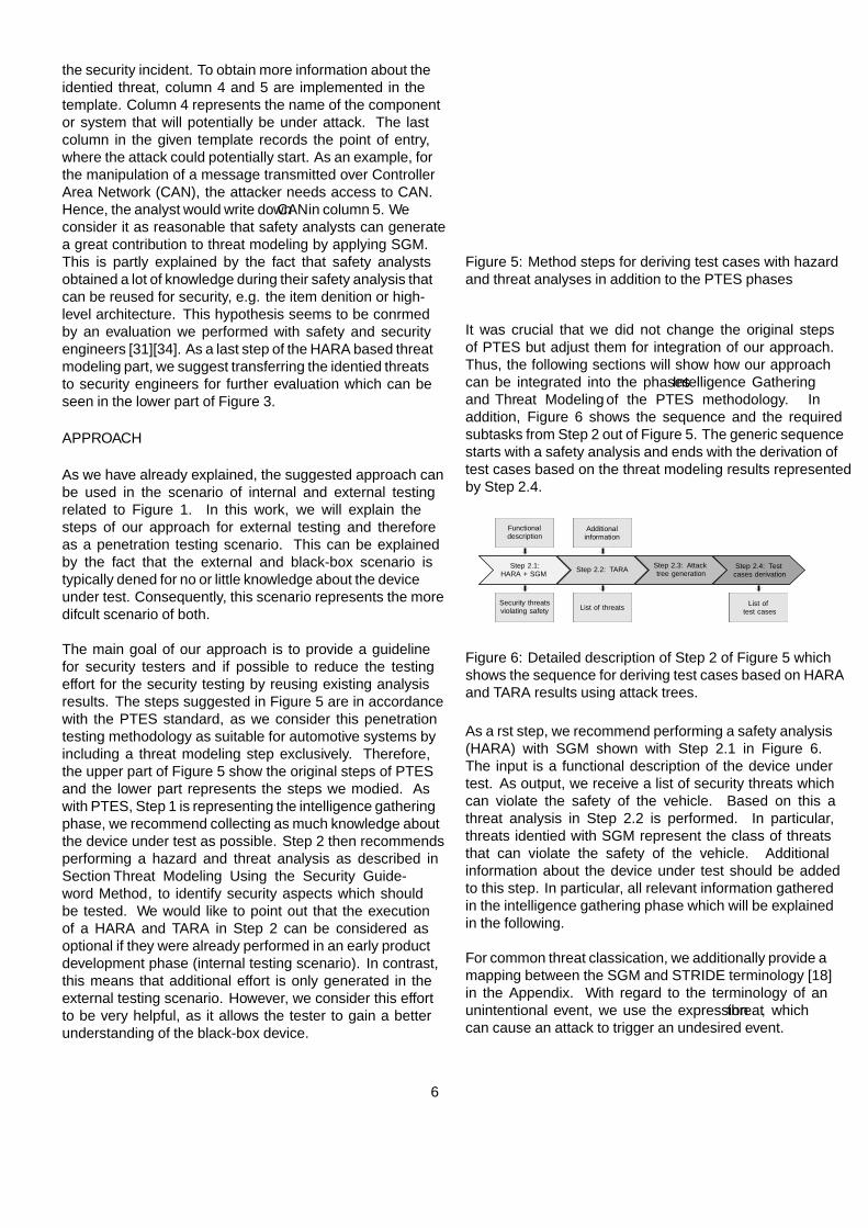
To illustrate the embedding of our SGM method in theestablished process of a safety analysis according toISO 26262, the individual steps are shown in Figure 4whereas Step 5 presents an additional step based on ourSGM approach. The method receives hazards as input,which were identified in the steps before. To systematicallyderive threats that can violate safety goals, we use eachidentified hazard with a set of guide-words, done as inHAZOP. For this, we provide a template which supportsthe structured threat analysis, shown in Table 2. Afterfinishing this step, the safety analysis continues with
2. Instantiate fault-type guide words
1. Provide an item definition
3. Situation classification
4. Identification of hazardous situations
5. Instantiate security guide-words and identify protection goals
6. Hazard classification
7. Threat classification using severity value of related hazards
Context diagram with data flow
Set of fault-type guide-words Situation database Hazard analysis profile
SGM template Classification based on ISO 26262
Risk assessment template
Figure 4: General safety analysis steps according toISO 26262 complemented with the steps for the SGM [31]which is represented by the dashed boxes.
determining risk values for each hazard, presented by step 6in Figure 4. Lastly, we take over the severity values ofstep 6 and use them as one parameter for determining riskvalues for threats identified with SGM.
Table 2: SGM template.
Hazardcan be
triggeredby
name ofmessage
orfunction
forcomponentor system
entrypoint
(1) (2) (3) (4) (5)
The template in Table 2 requires a hazard in column 1which was identified in the safety analysis (HARA). Incolumn 2 one security guide-word is required from the set:disclosure of information, disconnection of ECU, delay ofmessage or signal, deletion of message or signal, stoppingof ECU, triggering of (diagnostic) function, insertion ofmessage or signal, reset of ECU, manipulation of messageor signal and lastly manipulation of firmware.
Furthermore, in column 3 the analyst writes down the nameof the message or function which will be the objective of
5
the security incident. To obtain more information about theidentified threat, column 4 and 5 are implemented in thetemplate. Column 4 represents the name of the componentor system that will potentially be under attack. The lastcolumn in the given template records the point of entry,where the attack could potentially start. As an example, forthe manipulation of a message transmitted over ControllerArea Network (CAN), the attacker needs access to CAN.Hence, the analyst would write down CAN in column 5. Weconsider it as reasonable that safety analysts can generatea great contribution to threat modeling by applying SGM.This is partly explained by the fact that safety analystsobtained a lot of knowledge during their safety analysis thatcan be reused for security, e.g. the item definition or high-level architecture. This hypothesis seems to be confirmedby an evaluation we performed with safety and securityengineers [31][34]. As a last step of the HARA based threatmodeling part, we suggest transferring the identified threatsto security engineers for further evaluation which can beseen in the lower part of Figure 3.
APPROACH
As we have already explained, the suggested approach canbe used in the scenario of internal and external testingrelated to Figure 1. In this work, we will explain thesteps of our approach for external testing and thereforeas a penetration testing scenario. This can be explainedby the fact that the external and black-box scenario istypically defined for no or little knowledge about the deviceunder test. Consequently, this scenario represents the moredifficult scenario of both.
The main goal of our approach is to provide a guidelinefor security testers and if possible to reduce the testingeffort for the security testing by reusing existing analysisresults. The steps suggested in Figure 5 are in accordancewith the PTES standard, as we consider this penetrationtesting methodology as suitable for automotive systems byincluding a threat modeling step exclusively. Therefore,the upper part of Figure 5 show the original steps of PTESand the lower part represents the steps we modified. Aswith PTES, Step 1 is representing the intelligence gatheringphase, we recommend collecting as much knowledge aboutthe device under test as possible. Step 2 then recommendsperforming a hazard and threat analysis as described inSection Threat Modeling Using the Security Guide-word Method, to identify security aspects which shouldbe tested. We would like to point out that the executionof a HARA and TARA in Step 2 can be considered asoptional if they were already performed in an early productdevelopment phase (internal testing scenario). In contrast,this means that additional effort is only generated in theexternal testing scenario. However, we consider this effortto be very helpful, as it allows the tester to gain a betterunderstanding of the black-box device.
HARA with
use of SGM
Threat
modeling
Vulnerability
analysisExploitation Reporting
Step 2 Step 3 Step 4 Step 5
Threat
modeling
Vulnerability
analysisExploitation Reporting
Intelligence
gathering
Step 1
Intelligence
gathering
PTES
Our approach
Reuse threats that were identified in a
combined HARA and TARA.
Figure 5: Method steps for deriving test cases with hazardand threat analyses in addition to the PTES phases
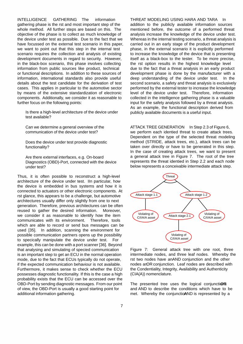
It was crucial that we did not change the original stepsof PTES but adjust them for integration of our approach.Thus, the following sections will show how our approachcan be integrated into the phases Intelligence Gatheringand Threat Modeling of the PTES methodology. Inaddition, Figure 6 shows the sequence and the requiredsubtasks from Step 2 out of Figure 5. The generic sequencestarts with a safety analysis and ends with the derivation oftest cases based on the threat modeling results representedby Step 2.4.
Step 2.1:HARA + SGM Step 2.2: TARA Step 2.3: Attack
tree generationStep 2.4: Testcases derivation
Functionaldescription
Security threatsviolating safety
Additionalinformation
List of threats List oftest cases
Figure 6: Detailed description of Step 2 of Figure 5 whichshows the sequence for deriving test cases based on HARAand TARA results using attack trees.
As a first step, we recommend performing a safety analysis(HARA) with SGM shown with Step 2.1 in Figure 6.The input is a functional description of the device undertest. As output, we receive a list of security threats whichcan violate the safety of the vehicle. Based on this athreat analysis in Step 2.2 is performed. In particular,threats identified with SGM represent the class of threatsthat can violate the safety of the vehicle. Additionalinformation about the device under test should be addedto this step. In particular, all relevant information gatheredin the intelligence gathering phase which will be explainedin the following.
For common threat classification, we additionally provide amapping between the SGM and STRIDE terminology [18]in the Appendix. With regard to the terminology of anunintentional event, we use the expression threat, whichcan cause an attack to trigger an undesired event.
6
INTELLIGENCE GATHERING The informationgathering phase is the first and most important step of thewhole method. All further steps are based on this. Theobjective of the phase is to collect as much knowledge ofthe device under test as possible. Due to the fact that wehave focussed on the external test scenario in this paper,we want to point out that this step in the internal testscenario requires the collection and analysis of existingdevelopment documents in regard to security. However,in the black-box scenario, this phase involves collectinginformation from public sources like product, technicalor functional descriptions. In addition to these sources ofinformation, international standards also provide usefuldetails about the test candidate for the derivation of testcases. This applies in particular to the automotive sectorby means of the extensive standardization of electroniccomponents. Additionally, we consider it as reasonable tofurther focus on the following points:
• Is there a high-level architecture of the device undertest available?
• Can we determine a general overview of thecommunication of the device under test?
• Does the device under test provide diagnosticfunctionality?
• Are there external interfaces, e.g. On-boardDiagnostics (OBD)-Port, connected with the deviceunder test?
Thus, it is often possible to reconstruct a high-levelarchitecture of the device under test. IIn particular, howthe device is embedded in bus systems and how it isconnected to actuators or other electronic components. Atfirst glance, this appears to be a challenge, but automotivearchitectures usually differ only slightly from one to nextgeneration. Therefore, previous architectures can be oftenreused to gather the desired information. Moreover,we consider it as reasonable to identify how the itemcommunicates with its environment. Therefore, toolswhich are able to record or send bus messages can beused [35]. In addition, scanning the environment forpossible communication partners opens up the possibilityto specifically manipulate the device under test. Forexample, this can be done with a port scanner [36]. Beyondthat analysing and simulating of specified communicationis an important step to get an ECU in the normal operationmode, due to the fact that ECUs typically do not operate,if the expected communication behaviour is not available.Furthermore, it makes sense to check whether the ECUpossesses diagnostic functionality. If this is the case a highprobability exists that the ECU can be accessed over theOBD-Port by sending diagnostic messages. From our pointof view, the OBD-Port is usually a good starting point foradditional information gathering.
THREAT MODELING USING HARA AND TARA Inaddition to the publicly available information sourcesmentioned before, the outcome of a performed threatanalysis increase the knowledge of the device under test.Whereas in the internal testing scenario, a threat analysis iscarried out in an early stage of the product developmentphase, in the external scenario it is explicitly performedto increase the knowledge of the device that is presentingitself as a black-box to the tester. To be more precise,the first option results in the highest knowledge leveldue to the fact that a threat analysis in an early productdevelopment phase is done by the manufacturer with adeep understanding of the device under test. In thesecond scenario, a safety and threat analysis is exclusivelyperformed by the external tester to increase the knowledgelevel of the device under test. Therefore, informationcollected in the intelligence gathering phase is a valuableinput for the safety analysis followed by a threat analysis.As an example, the functional description derived frompublicly available documents is a useful input.
ATTACK TREE GENERATION In Step 2.3 of Figure 6,we perform each identified threat to create attack trees.Dependent on the type of the selected threat modelingmethod (STRIDE, attack trees, etc.), attack trees can betaken over directly or have to be generated in this step.In the case of creating attack trees, we want to presenta general attack tree in Figure 7. The root of the treerepresents the threat identified in Step 2.2 and each nodebelow represents a conceivable intermediate attack step.
Threat
Attack stage 1.1
Violating ofC/I/A/A asset
Attack stage 1.2
Attack stage 2.1
Violating ofC/I/A/A asset
Violating ofC/I/A/A asset
Figure 7: General attack tree with one root, threeintermediate nodes, and three leaf nodes. Whereby thefirst two nodes have an AND conjunction and the othernodes an OR conjunction. Leaf nodes are described withthe Confidentiality, Integrity, Availability and Authenticity(CIA(A)) nomenclature.
The presented tree uses the logical conjunctions ORand AND to describe the conditions which have to bemet. Whereby the conjunction AND is represented by a
7
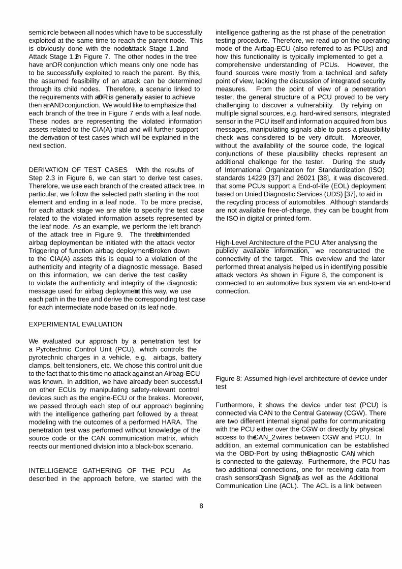
semicircle between all nodes which have to be successfullyexploited at the same time to reach the parent node. Thisis obviously done with the nodes Attack Stage 1.1 andAttack Stage 1.2 in Figure 7. The other nodes in the treehave an OR conjunction which means only one node hasto be successfully exploited to reach the parent. By this,the assumed feasibility of an attack can be determinedthrough its child nodes. Therefore, a scenario linked tothe requirements with an OR is generally easier to achievethen an AND conjunction. We would like to emphasize thateach branch of the tree in Figure 7 ends with a leaf node.These nodes are representing the violated informationassets related to the CIA(A) triad and will further supportthe derivation of test cases which will be explained in thenext section.
DERIVATION OF TEST CASES With the results ofStep 2.3 in Figure 6, we can start to derive test cases.Therefore, we use each branch of the created attack tree. Inparticular, we follow the selected path starting in the rootelement and ending in a leaf node. To be more precise,for each attack stage we are able to specify the test caserelated to the violated information assets represented bythe leaf node. As an example, we perform the left branchof the attack tree in Figure 9. The threat Unintendedairbag deployment can be initiated with the attack vectorTriggering of function airbag deployment. Broken downto the CIA(A) assets this is equal to a violation of theauthenticity and integrity of a diagnostic message. Basedon this information, we can derive the test case: Tryto violate the authenticity and integrity of the diagnosticmessage used for airbag deployment. In this way, we useeach path in the tree and derive the corresponding test casefor each intermediate node based on its leaf node.
EXPERIMENTAL EVALUATION
We evaluated our approach by a penetration test fora Pyrotechnic Control Unit (PCU), which controls thepyrotechnic charges in a vehicle, e.g. airbags, batteryclamps, belt tensioners, etc. We chose this control unit dueto the fact that to this time no attack against an Airbag-ECUwas known. In addition, we have already been successfulon other ECUs by manipulating safety-relevant controldevices such as the engine-ECU or the brakes. Moreover,we passed through each step of our approach beginningwith the intelligence gathering part followed by a threatmodeling with the outcomes of a performed HARA. Thepenetration test was performed without knowledge of thesource code or the CAN communication matrix, whichreflects our mentioned division into a black-box scenario.
INTELLIGENCE GATHERING OF THE PCU Asdescribed in the approach before, we started with the
intelligence gathering as the first phase of the penetrationtesting procedure. Therefore, we read up on the operatingmode of the Airbag-ECU (also referred to as PCUs) andhow this functionality is typically implemented to get acomprehensive understanding of PCUs. However, thefound sources were mostly from a technical and safetypoint of view, lacking the discussion of integrated securitymeasures. From the point of view of a penetrationtester, the general structure of a PCU proved to be verychallenging to discover a vulnerability. By relying onmultiple signal sources, e.g. hard-wired sensors, integratedsensor in the PCU itself and information acquired from busmessages, manipulating signals able to pass a plausibilitycheck was considered to be very difficult. Moreover,without the availability of the source code, the logicalconjunctions of these plausibility checks represent anadditional challenge for the tester. During the studyof International Organization for Standardization (ISO)standards 14229 [37] and 26021 [38], it was discovered,that some PCUs support a End-of-life (EOL) deploymentbased on Unified Diagnostic Services (UDS) [37], to aid inthe recycling process of automobiles. Although standardsare not available free-of-charge, they can be bought fromthe ISO in digital or printed form.
High-Level Architecture of the PCU After analysing thepublicly available information, we reconstructed theconnectivity of the target. This overview and the laterperformed threat analysis helped us in identifying possibleattack vectors. As shown in Figure 8, the component isconnected to an automotive bus system via an end-to-endconnection.
CentralGateway
Speed SensorECU
PCU
Gyro Signals
Crash Signals
CAN_1 CAN_2
DiagnosticCAN
OBD-II Port Additional Communication Line (ACL)
Figure 8: Assumed high-level architecture of device undertest
Furthermore, it shows the device under test (PCU) isconnected via CAN to the Central Gateway (CGW). Thereare two different internal signal paths for communicatingwith the PCU either over the CGW or directly by physicalaccess to the CAN_2 wires between CGW and PCU. Inaddition, an external communication can be establishedvia the OBD-Port by using the Diagnostic CAN, whichis connected to the gateway. Furthermore, the PCU hastwo additional connections, one for receiving data fromcrash sensors (Crash Signals) as well as the AdditionalCommunication Line (ACL). The ACL is a link between
8
PCU and OBD-Port. The connection is intended as anadditional communication line in besides to the CANcommunication. Manufacturers can use this additionalcommunication to adapt the EOL detonation process totheir needs [38]. To clarify, both connections are hard-wired in the physical sense, but we are going to refer to theend-to-end connections as hard-wired signals in this work.
THREAT MODELING FOR THE PCU We performeda safety analysis for the selected device (PCU) and itsdefinition, shown in Figure 8. As a result, we identifiedseveral hazards with the HAZOP approach and rankedUnintended airbag deployment as well as Unintendedprevention of airbag deployment as the most criticalhazards. After a discussion with safety engineers, wedecided to focus on Unintended airbag deployment due toits high probability to injure passengers. Consequently, weapplied the SGM approach as suggested in Figure 6 andwere able to identify several threats, which could probablycause a deployment of charges. For reason of presentation,we present only the following threats and how we usedthem further.
1. Unintended airbag deployment can be triggered bytriggering of (diagnostic) function airbag deployment.
2. Unintended airbag deployment can be triggered bymanipulation of message diagnostic message.
3. Unintended airbag deployment can be triggered bymanipulation of message crash message.
The first threat describes an unauthorized activation ofa standard or diagnostic function of the PCU. Forclarification, a standard function, in our view, is a functionwhich is implemented in a way to run during normaloperation, e.g. triggering airbags after an accident. Theother type of function (diagnostic function) is implementedto support technicians in workshops to solve problemsduring repairs. This type of function has shown a highprobability to get exploited in the last years [39]. Besidesthis, Threat 1 has a high probability to be existent inour device under test, since almost all ECUs controllingactuators possess functions for self-diagnostics. Besidesthe unauthorized activation of a diagnostic function, itis possible to manipulate a message which is used by adiagnostic function. This case is represented by Threat 2and can result in an undefined behaviour leading toairbag detonation as well. Lastly, Threat 3 describes themanipulation of a message which contains the informationabout accident detection. For example, such messages aretypically sent by intelligent crash sensors to the Airbag-ECU.
ATTACK TREE GENERATION FOR THE PCU Asproposed by our approach, we generate attack trees for
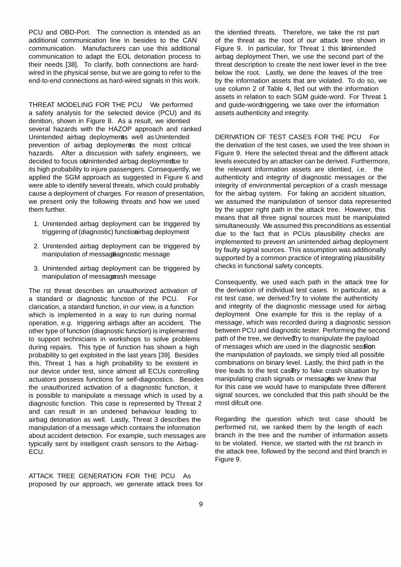
the identified threats. Therefore, we take the first partof the threat as the root of our attack tree shown inFigure 9. In particular, for Threat 1 this is Unintendedairbag deployment. Then, we use the second part of thethreat description to create the next lower level in the treebelow the root. Lastly, we define the leaves of the treeby the information assets that are violated. To do so, weuse column 2 of Table 4, filled out with the informationassets in relation to each SGM guide-word. For Threat 1and guide-word triggering, we take over the informationassets authenticity and integrity.
DERIVATION OF TEST CASES FOR THE PCU Forthe derivation of the test cases, we used the tree shown inFigure 9. Here the selected threat and the different attacklevels executed by an attacker can be derived. Furthermore,the relevant information assets are identified, i.e. theauthenticity and integrity of diagnostic messages or theintegrity of environmental perception of a crash messagefor the airbag system. For faking an accident situation,we assumed the manipulation of sensor data representedby the upper right path in the attack tree. However, thismeans that all three signal sources must be manipulatedsimultaneously. We assumed this preconditions as essentialdue to the fact that in PCUs plausibility checks areimplemented to prevent an unintended airbag deploymentby faulty signal sources. This assumption was additionallysupported by a common practice of integrating plausibilitychecks in functional safety concepts.
Consequently, we used each path in the attack tree forthe derivation of individual test cases. In particular, as afirst test case, we derived: Try to violate the authenticityand integrity of the diagnostic message used for airbagdeployment. One example for this is the replay of amessage, which was recorded during a diagnostic sessionbetween PCU and diagnostic tester. Performing the secondpath of the tree, we derived: Try to manipulate the payloadof messages which are used in the diagnostic session. Forthe manipulation of payloads, we simply tried all possiblecombinations on binary level. Lastly, the third path in thetree leads to the test case: Try to fake crash situation bymanipulating crash signals or message. As we knew thatfor this case we would have to manipulate three differentsignal sources, we concluded that this path should be themost difficult one.
Regarding the question which test case should beperformed first, we ranked them by the length of eachbranch in the tree and the number of information assetsto be violated. Hence, we started with the first branch inthe attack tree, followed by the second and third branch inFigure 9.
9
Unintendedairbag deployment
Triggering offunction airbag deployment
Violate authenticity and integrity ofdiagnostic messages
Manipulation ofmessage diagnostic message
Violate integrity ofdiagnostic messages
Manipulation ofmessage crash message
Manipulation ofmessage crash signals
Violate integrity ofcrash signals
Manipulation ofmessage speed signals
Violate integrity ofspeed signals
Manipulation ofmessage gyro signals
Violate integrity ofgyro signals
Figure 9: Attack tree for the threat "‘Unintended airbag deployment"’ using SGM nomenclature
EXPLOITING OF IDENTIFIED VULNERABILITIESIn this section, we want to show how we performed theselected test cases in our penetration test. Due to thelength of this paper, we will show the procedure usingthe threat Unintended airbag deployment can be triggeredby triggering of (diagnostic) function airbag deploymentas an example. Hereby the threat is represented by theleft branch of the attack tree in Figure 9. The relatedtest case for this threat is Try to violate the authenticityand integrity of the diagnostic message used for airbagdeployment. In combination with the knowledge collectedin the intelligence gathering phase and the reference to theEOL standard, we decided on trying to gain unauthorizedaccess to diagnostic based EOL functionality.
Identification of Vulnerable Vehicles In a first step, wehad to check the implementation of the EOL capabilityaccording to the ISO standard. Therefore, a diagnostic scan(UDS) on the test vehicles was performed. The standardmandates that the first Airbag-ECU inside a vehicle listensand replies to diagnostic requests (UDS) with the CAN IDshown in Table 3. This is the so-called fixed-address andenables us to directly identify if an Airbag-ECU (PCU) hasimplemented the relevant EOL standard.
Table 3: CAN IDs for communication with fixed-addressPCU regarding the airbag standard [38]
11 bit CAN ID 29 bit CAN IDRequest 0x7F1 0x18DA53F1Response 0x7F9 0x18DAF153
In the case that a vehicle contains more than one airbagunit, the CAN IDs of the other units can be requestedvia a diagnostic service reached from the first Airbag-ECU (fixed-address PCU). If a PCU does not respond tothe sent messages, it can be assumed directly that the EOLstandard has not been implemented.
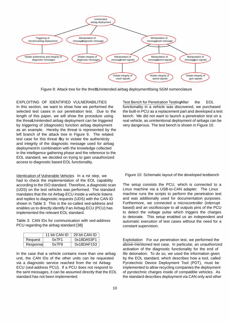
Test Bench for Penetration Testing After the EOLfunctionality in a vehicle was discovered, we purchasedthe built-in PCU as a replacement part and developed a testbench. We did not want to launch a penetration test on areal vehicle, as unintentional deployment of airbags can bevery dangerous. The test bench is shown in Figure 10.
PCUCAN
Oscilloscope
Power Supply
USB2CAN
µC detectingdeployment
USB1
USB2
Charges
Control12V
Testbench
Attacker
*Linux machinerunning
attack script
PC *
Figure 10: Schematic layout of the developed testbench
The setup consists the PCU, which is connected to aLinux machine via a USB-to-CAN adapter. The Linuxmachine runs the scripts to perform the penetration testand was additionally used for documentation purposes.Furthermore, we connected a microcontroller (interruptbased) and an oscilloscope to all outputs pins of the PCUto detect the voltage pulse which triggers the chargesto detonate. This setup enabled us an independent andautomatic execution of test cases without the need for aconstant supervision.
Exploitation For our penetration test, we performed theabove-mentioned test case. In particular, an unauthorizedactivation of the diagnostic functionality for the end oflife detonation. To do so, we used the information givenby the EOL standard, which describes how a tool, calledPyrotechnic Device Deployment Tool (PDT), must beimplemented to allow recycling companies the deploymentof pyrotechnic charges inside of compatible vehicles. Asthe standard describes deployment via CAN only and other
10
methods including an additional wired connection (ACL),a target without that additional connection was selected.
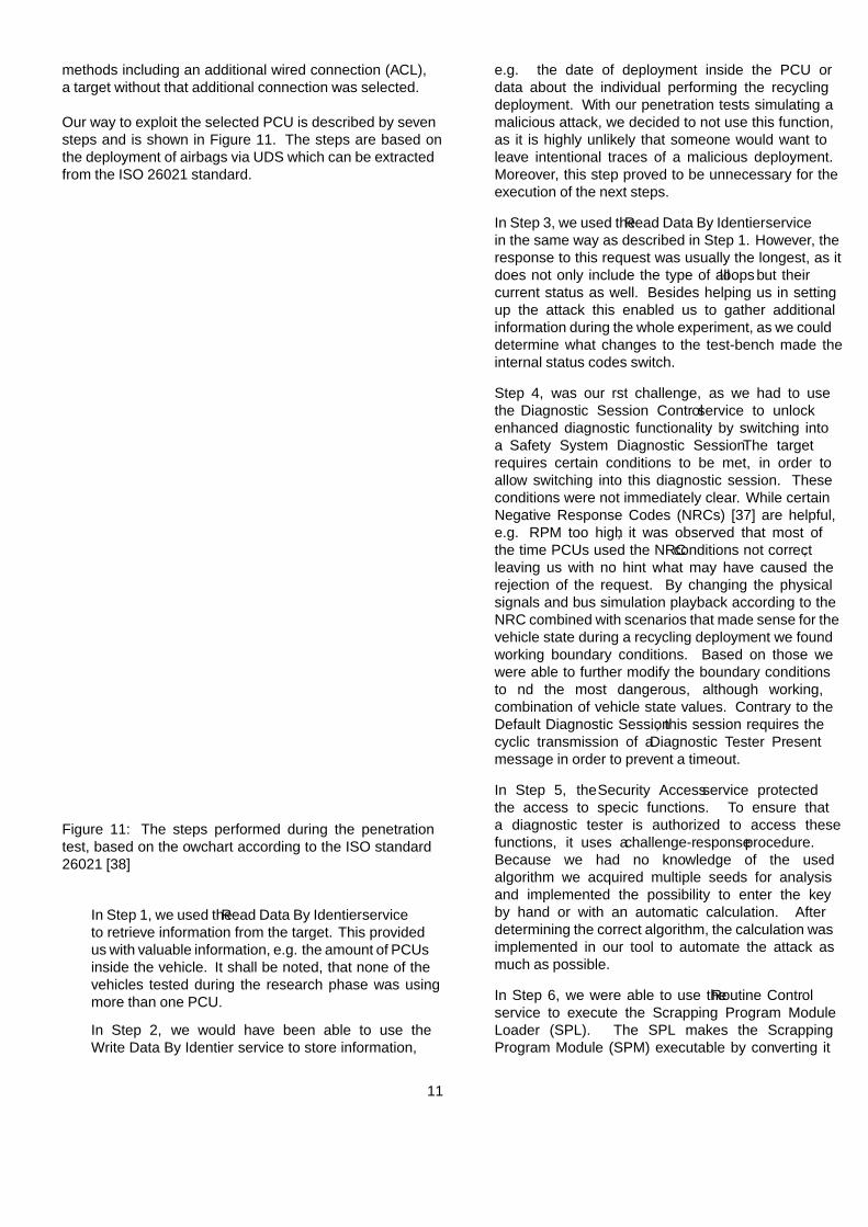
Our way to exploit the selected PCU is described by sevensteps and is shown in Figure 11. The steps are based onthe deployment of airbags via UDS which can be extractedfrom the ISO 26021 standard.
Read deployment method version
Read number of PCUs
Read address info of PCUs
Read VIN (optional)
Write documentation (optional)
Read Loop table of PCU
Initiate SafetySystemDiagnosticSession
Enable SecurityAccess
Execute SPL
Device scrapping
End PCU
Next PCU
Next device
1
2
3
4
5
6
7
Figure 11: The steps performed during the penetrationtest, based on the flowchart according to the ISO standard26021 [38]
• In Step 1, we used the Read Data By Identifier serviceto retrieve information from the target. This providedus with valuable information, e.g. the amount of PCUsinside the vehicle. It shall be noted, that none of thevehicles tested during the research phase was usingmore than one PCU.
• In Step 2, we would have been able to use theWrite Data By Identifier service to store information,
e.g. the date of deployment inside the PCU ordata about the individual performing the recyclingdeployment. With our penetration tests simulating amalicious attack, we decided to not use this function,as it is highly unlikely that someone would want toleave intentional traces of a malicious deployment.Moreover, this step proved to be unnecessary for theexecution of the next steps.
• In Step 3, we used the Read Data By Identifier servicein the same way as described in Step 1. However, theresponse to this request was usually the longest, as itdoes not only include the type of all loops but theircurrent status as well. Besides helping us in settingup the attack this enabled us to gather additionalinformation during the whole experiment, as we coulddetermine what changes to the test-bench made theinternal status codes switch.
• Step 4, was our first challenge, as we had to usethe Diagnostic Session Control service to unlockenhanced diagnostic functionality by switching intoa Safety System Diagnostic Session. The targetrequires certain conditions to be met, in order toallow switching into this diagnostic session. Theseconditions were not immediately clear. While certainNegative Response Codes (NRCs) [37] are helpful,e.g. RPM too high, it was observed that most ofthe time PCUs used the NRC conditions not correct,leaving us with no hint what may have caused therejection of the request. By changing the physicalsignals and bus simulation playback according to theNRC combined with scenarios that made sense for thevehicle state during a recycling deployment we foundworking boundary conditions. Based on those wewere able to further modify the boundary conditionsto find the most dangerous, although working,combination of vehicle state values. Contrary to theDefault Diagnostic Session, this session requires thecyclic transmission of a Diagnostic Tester Presentmessage in order to prevent a timeout.
• In Step 5, the Security Access service protectedthe access to specific functions. To ensure thata diagnostic tester is authorized to access thesefunctions, it uses a challenge-response procedure.Because we had no knowledge of the usedalgorithm we acquired multiple seeds for analysisand implemented the possibility to enter the keyby hand or with an automatic calculation. Afterdetermining the correct algorithm, the calculation wasimplemented in our tool to automate the attack asmuch as possible.
• In Step 6, we were able to use the Routine Controlservice to execute the Scrapping Program ModuleLoader (SPL). The SPL makes the ScrappingProgram Module (SPM) executable by converting it
11
in executable code and moving it into the PCU’sRAM. Without these two steps a deployment usingthis attack vector is not possible. After successfullyperforming these preparations we used the RoutineControl service for the third time to deploy a specificcharge. This specific charge is selected via sendingthe loop ID in the 5th byte of the Routine Controlmessage. In case more than one pyrotechnic chargeis available for deployment, the message can be sentagain with the new loop ID in place. During ourexperiment, we decided to deploy a single loop andmonitor the PCU’s output and internal status values.
• In Step 7, we ended the scrapping of attached chargesby using the EcuReset service to hardreset the PCU.In this case, performing a hardreset power cycled thePCU, leading to the loss of data stored inside theRandom-access Memory (RAM). Thus, stopping theability to deploy charges, as the necessary code is onlyexecutable after performing the required conversionsteps in the on-state as described in Step 6.
PENETRATION TEST RESULTS Related to Step 5in Figure 5 we reported the vulnerabilities, which werediscovered during the penetration test. We discoveredissues exclusively based on the software implementation,e.g. the weak security access and we discovered issueswhere the weakness consists of an unused combination ofhard- and software.
Vulnerability in Security Access With the SecurityAccess service having a history of being exploited,this access was assumed to possess a vulnerability. Inparticular, the algorithms analysed so far violate theKerckhoff’s Principle [40] by using the algorithm as secretinstead of the key. In this case, we analysed multipleseeds to check for patterns and the overall amount ofdifferent seeds provided by the target. Here, the giventarget provided new seeds for different requests and afterthe target has been power cycled.
While studying the EOL standard, we discovered thedescription of the implementation for the Security Accessservice to protect against unauthorized deployment. Thisis followed by an example demonstrating the exchangeof seed and key. In this example, a 2-byte seed isshown, where the value in the most significant byte is theversion number of the implemented standard. The leastsignificant byte is a random value. For the calculation ofthe corresponding key, i.e., the secret, one’s complementof the seed is used. Standards usually provide an exampleof the process and some suggestions for an algorithm, e.g.the UDS standard [37] clearly states that the example in itsSecurity Access section is just one way of implementing thesecret.
Sending a key calculated by one’s complement of thesupplied seed, the authentication attempt proved to besuccessful and unlocked the target. However, in ourpractical evaluation, we found that this given example inthe standard is used in a PCU series unit in-field whichcontradicts the fact that in the given challenge-responseapproach the algorithm should be secret. As this algorithmis simple, an attacker can easily check if the given exampleis implemented. Furthermore, he is also able to easilycompromise the PCU by providing the key to the PCU afterthe seed is sent. Besides using this simple algorithm forthe calculation of the key, the length is extremely short andnot even used to its full capabilities. By using the versionnumber of the standard in the most significant byte, only256 different seeds can be provided by the target as only theleast significant byte is changing. This makes it even morevulnerable for exploitation, e.g. by a brute force attack.
To verify the exploitation of this vulnerability we usedthe test bench in Figure 10 for the selected target andexecuted all the necessary steps according to the EOLstandard. To ensure the functionality of the target, thepyrotechnic charges were simulated by attaching resistorsto the corresponding pins on the connector of the target.To enable the EOL functionality CAN traffic was replayed,consisting of only one message including a vehicle speedof zero. This CAN bus only included the target and a CANtransceiver sending the diagnostic messages and playingback the aforementioned vehicle speed message. Theexploitation was successfully validated by an oscilloscopedisplaying the firing impulse. The related CommonVulnerabilities and Exposures (CVE)-ID is listed underCVE-2017-14937 [41]. In addition, a module for theMetasploit Hardware Bridge was developed in cooperationwith the security researcher Craig Smith [42]. The modulecan test for the presence of this vulnerability in a vehiclewithout the possibility of actually deploy the charges [43].
Lack of Plausibility Checks The observed PCU with thegiven functionality has access to information from hard-wired signal sources and bus messages. However, itdoes not use all of them to derive if the current stateof the vehicle is correct. In fact, it only required oneCAN message, containing the vehicle speed, and physicalrequirements to enable deployment on the test bench usedfor this work. The physical requirements were connectedpyrotechnic charges, in our case the substitution of thoseby appropriate resistors, and the ignition beeing turnedon or the engine running (if installed in a real vehicle).Further attached hard-wired signals like seat occupancywere present on the connector of our target but not used.
Combined with the fast and highly automated procedureof the attack, this leads to the possibility of maliciousdeployment while the engine is running and people residein the car, e.g. while waiting at a stoplight. This
12
should be seen as a real threat, as the remote exploitationof passenger vehicles, specifically getting access to theCAN bus via remote connections has been demonstratedbefore [44][45]. Besides, it is conceivable that hackersdistribute malicious OBD-Dongles on sales platformson the Internet. Furthermore, OBD-Dongles sold bymanufactures can also give the required access to theinternal vehicle network. In a worst-case scenario, thiscould lead to remote access [46]. Both options could leadto a scaled attack on different types of cars from severalmanufactures as the vulnerability is part of an internationalstandard.
COUNTERMEASURES In general, software should bedesigned from the ground up as secure as possible byapplying Security by Design during the developmentprocess. There are several security principles, whichsoftware architects should consider. The followingcountermeasures are only examples for our observed targetbased on the mentioned principles.
Selection of Suitable Technologies Documentedexploitation of passenger vehicles was achieved inmultiple cases by sending or replaying CAN messageson the target’s bus. CAN can be seen as a bus systemnot designed with security issues in mind. Especiallythe lack of authentication of message sources is oneof the main problems of CAN. By using cryptographicauthentication methods coupled with integrity protectionand a freshness value, this problem can be mitigated. Anexample of this is an Keyed-Hash Message AuthenticationCode (HMAC) of the transmitted message, including afreshness value to prevent replay attacks. In addition,techniques such as threat modeling [18][31] can providevaluable information to select specific security measuresfor implementation. Furthermore, ACL’s bidirectionalcommunication capability [47] provides the ability to addan authentication process using a recognized method suchas digital certificates. Moreover, the mandatory use of anACL line on the Airbag-ECU as an additional plausibilitycheck could have prevented exploitation by a single CANmessage.
Hard-wired Plausibility Checks The connector of ourtarget was designed to accommodate over 100 pins.Although the presence of pins depends on the exact modelthe target is installed in, this high number is explained bythe presence of physical signals being directly connectedto the target. Besides the obvious need for hard-wiredconnections, e.g. the connection to the pyrotechniccharges, it was discovered that signals such as seatbeltstatus and seat occupancy were connected as well. Whilethis does not exclude the possibility of information beingtransmitted over a bus system as well, this would allow for
plausibility checks based on sources that are not easy to betampered [48].
Usage of Cryptography When developers want to designa new security feature, they should follow the Kerckhoff’sPrinciple [40]. The principle explicitly describesthat cryptosystems shouldn’t be secure due to hiddendetails about how the algorithm works (security byobscurity). Moreover, the whole secret should be basedon the confidentiality of the used key. The past hasalready shown multiple times that mechanisms whichdisregard the mentioned principle are often broken assoon as the algorithm has been reverse-engineered [49].Our investigation has also confirmed the violation ofthe mentioned principle by analysing the sent seed.A first approach to fix the existing issue could bean additional security layer which ensures a correctauthentication. However, the best solution to theproblem is to use generally recommended cryptographicalgorithms such as the Advanced Encryption Standard(AES) [50]. The AUTomotive Open System ARchitecture(AUTOSAR) members have already recognized thenecessity of the mentioned security goals for futureon-board communication. For this reason, they havestandardized the SecOC module [51], which includesauthentication mechanisms on the level of Protocol DataUnits (PDUs). The specification does not define a specificmethod for creating a Message Authentication Code(MAC), but rather recommends standardized cryptographicalgorithms and defines the payload of a secured PDUwith a freshness value and an authenticator for protectingagainst replay attacks and unauthorized manipulation of themessage.
Hardening Against Brute-Force Attacks The use ofNegative Response Codes (NRCs), such as the exceedednumber of attempts and required time delay not expired, asdescribed in the UDS standard could be used to slow downbrute-force attempts. While the former would requirea power cycle of the target to continue the brute-forceattempt, the latter would slow the approach down. Tocounter the use of scripted power cycling of the targetin rapid succession, the target could require a certaintime delay after being powered on, before enabling thediagnostic capability. The length of the seed and keycould be increased to harden the target against brute-forceattempts. As mentioned before the length of 2 bytesleads to 65536 possible keys per seed. By using the mostsignificant byte for the version number of the implementedISO standard, the most significant byte is fixed in everyseed. Thus, by only changing the values of the leastsignificant byte, only 256 different seeds can be suppliedby the target after a request, although the seed is 16 bitslong. Consequently, this reduces the number of maximumtries to unlock the Security Access, as the same seeds occur
13
more frequently, which enables a faster iteration over thepossible keys. Besides this problem, we recommend toincrease the key length significantly. In combination witha suitable algorithm such as AES, a key length of 128 bitsis recommended [52][53].
Authorization Mechanisms Our own research resultsregarding the airbag vulnerability have shown again that anunlocked Security Access has a high potential for a safetycritical impact. Moreover, this type of security mechanismensures only the authentication. Compared with networksystems from the traditional IT, vehicles don’t have anymechanisms for authorization and access control. A firstapproach to implement such features proposed Kim etal. [54] with an approach of an Attribute Based AccessControl (ABAC) for the AUTOSAR software architecturebased on different attributes of diagnostic CAN messages.Another ABAC approach was published by Berger etal. [55] for integrating this kind of access control in firewallsystems. This provides new features such as dynamicaccess decisions based on environmental conditions suchas time or location of the requester. Transferred toautomotive systems, it will also be important for futurevehicles to implement dynamic and distributed firewallsto address upcoming requirements due to increasinginterconnectivity with their infrastructure, other cars orcloud-based functionalities. Furthermore, ABAC couldalso be useful for enforcing access controls based ondifferent vehicle states. For instance, in one of our testedvehicles, the gateway did not check for the appropriateconditions, before performing certain diagnostic functions.As a consequence of this, diagnostic functions areavailable during vehicle conditions in which there wouldbe malicious applications for them. This includes enteringa diagnostic session specifically for safety systems, e.g.airbags, at highway speeds. Thus, it is probable that evenmore implementation flaws exist in our target which are yetto be discovered.
CONCLUSION AND FUTURE WORK
In this work we have developed an approach to reusethe results of a threat analysis for automotive securitytesting. A structured methodology for deriving testcases using attack trees was presented. In addition,the presented approach shows how exactly the resultsof a safety analysis can be reused to identify threatsthat can compromise vehicle safety. To identify thisparticular type of threat, we have shown how our recentlypublished approach can be used. Furthermore, we haveprovided a mapping between the nomenclature of ourthreat identification approach and STRIDE for an easierintegration into existing threat modeling methods. Finally,we demonstrated the applicability of our method byan experimental evaluation with an Airbag-ECU. In
particular, the preparation and execution of the penetrationtests for the Airbag-ECU demonstrated the applicabilityof the proposed methodology steps. As a result of thispenetration test, a vulnerability was discovered that allowsunintentional detonation of airbags.
In the next steps, we want to further formalize ourapproach. This could help us to create test cases witha detailed description for the concrete selection of attackvectors. Such a detailed test case description can further beused to develop specific testing tools. In general, we wantto offer a computer-aided version of our approach to reducethe total testing effort. Furthermore, we want to analyse apossible reuse of functional requirements as further inputfor our approach.
APPENDIX
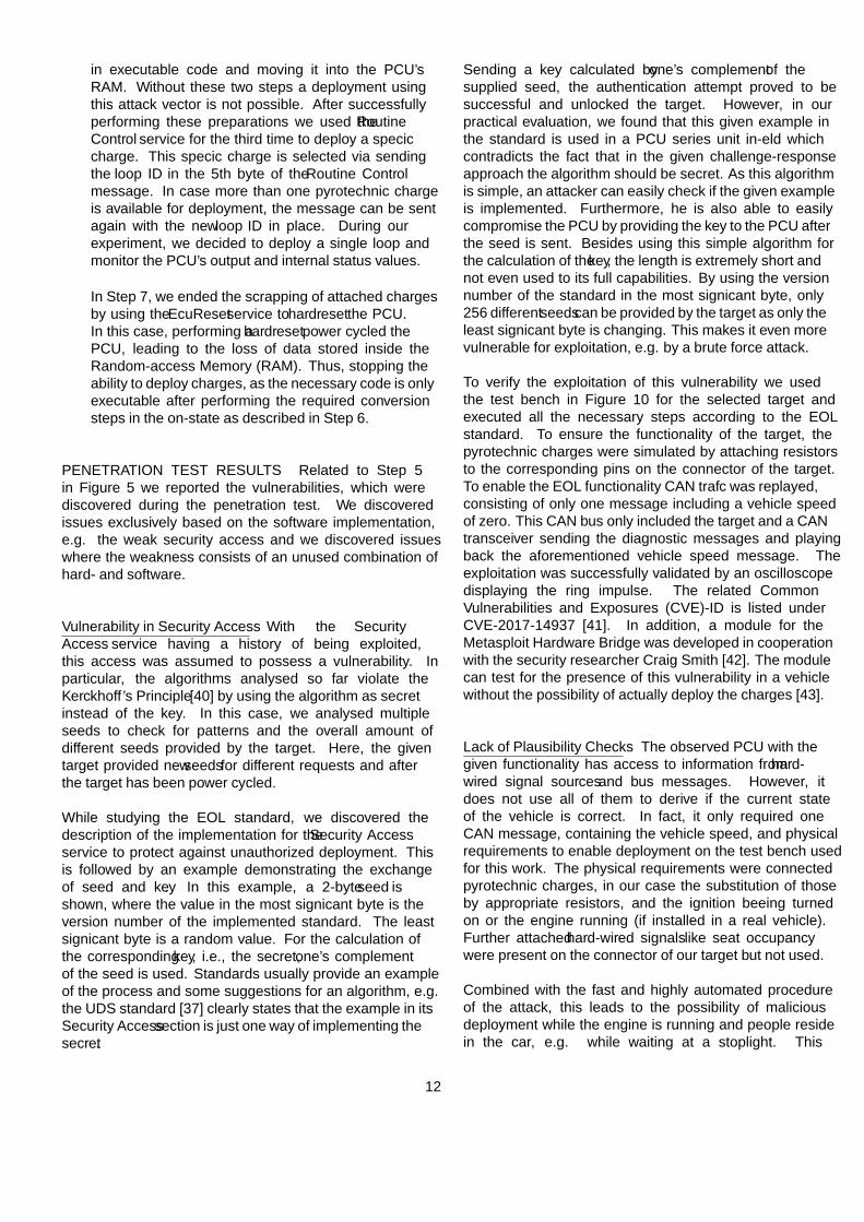
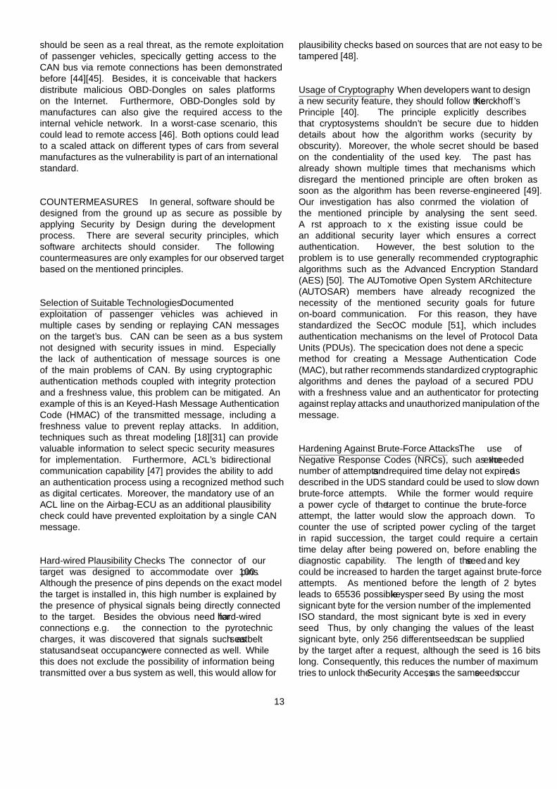
For an easier integration in existent approaches we wantto provide a mapping between SGM guide-words and theCIA(A) triad in Table 4. This further allows us to providea mapping between SGM and STRIDE. We providethis transformation ability between SGM and STRIDEdue to the fact that STRIDE nomenclature is well-knownin security and commonly used. As one example forthe mapping, we utilize the threat Unintended airbagdeployment can be triggered by triggering of (diagnostic)function airbag deployment. that was built with the guide-word triggering of (diagnostic) function. For this guide-word, we propose to select spoofing from Table 4 as pedantfor STRIDE. With this, we can transform the threatdescription to Spoofing of (diagnostic) function presentingthe STRIDE nomenclature. We do this for the othertwo threats as well, leading to an attack tree in STRIDEnomenclature shown in Figure 12.
Table 4: Mapping from SGM to STRIDE nomenclature,with the CIA(A) triad as intermediate mapping step
SGM CIA(A) STRIDEtriggering authenticity,
integrityspoofing
insertion integrity tampering
manipulation integrity tampering
disconnection availability denial-of-service
delay availability denial-of-service
deletion availability denial-of-service
stopping availability denial-of-service
reset availability denial-of-service
ACKNOWLEDGEMENTS
This work has been developed in the projects SAFEME ASAP (reference number: 03FH011IX5) and AUTO-
14
Unintendedairbag deployment
Spoofing ofdiagnostic functionairbag deployment
Violate authenticity and integrityof diagnostic messages
Tampering ofdiagnostic message
Violate integrity ofdiagnostic messages
Tampering ofcrash message
Tampering ofcrash signals
Violate integrity ofcrash signals
Tampering ofspeed signals
Violate integrity ofspeed signals
Tampering ofgyro signals
Violate integrity ofgyro signals
Figure 12: Attack tree for the threat Unintended airbag deployment after the transformation to the STRIDE nomenclature byusing the mapping in Table 4
SIMA (reference number: 13FH006IX6) which are partlyfunded by the German ministry of education and research(BMBF) within the research programme ICT 2020.
References
[1] R. N. Charette, “This Car Runs onCode,” 2009, accessed 12.02.2016. [Online].Available: http://spectrum.ieee.org/transportation/systems/this-car-runs-on-code
[2] C. Miller and C. Valasek, “A survey of remoteautomotive attack surfaces,” Black Hat USA, vol.2014, 2014.
[3] S. Checkoway, D. McCoy, B. Kantor, D. Anderson,H. Shacham, S. Savage, K. Koscher, A. Czeskis,F. Roesner, T. Kohno et al., “ComprehensiveExperimental Analyses of Automotive AttackSurfaces,” in USENIX Security Symposium, 2011.
[4] C. Valasek and C. Miller, “CAN MessageInjection: OG Dynamite Edition,” last checkedon 05.04.2017. [Online]. Available: http://illmatics.com/can%20message%20injection.pdf
[5] A. Greenberg, “Tesla Responds to ChineseHack With a Major Security Upgrade,”last checked on 23.03.2017. [Online].Available: https://www.wired.com/2016/09/tesla-responds-chinese-hack-major-security-upgrade/
[6] H. H. Thompson, “Application penetration testing,”IEEE Security and Privacy Magazine, vol. 3, no. 1,pp. 66–69, 2005.
[7] M. Felderer, M. Büchler, M. Johns, A. D. Brucker,R. Breu, and A. Pretschner, “Security testing: Asurvey,” in Advances in Computers. Elsevier, 2016,vol. 101, pp. 1–51.
[8] ISECOM, “Open source security testingmethodology manual,” Internet. [Online]. Available:http://www.isecom.org/research/
[9] NIST, “Technical guide to information securitytesting and assessment,” Internet. [Online].Available: http://nvlpubs.nist.gov/nistpubs/Legacy/SP/nistspecialpublication800-115.pdf
[10] OISSG, “Information systems security assessmentframework,” Internet. [Online]. Available:http://cuchillac.net/archivos/pre_seguridad_pymes/2_hakeo_etico/lects/metodologia_oissg.pdf
[11] F. Gontharet, “ISSAF – Methodology Analysisand Critical Evaluation),” 2015. [Online].Available: https://wr0ng.name/other/REPORT_PenetrationTesting_Methodology.pdf
[12] PTES, “Penetration testing execution standard,”Internet. [Online]. Available: http://www.pentest-standard.org
[13] OWASP, “Open web application security project- testing guide v4,” Internet. [Online]. Available:https://www.owasp.org/images/1/19/OTGv4.pdf
[14] SAE, “Cybersecurity Guidebook for Cyber-PhysicalVehicle Systems,” 01.2016, accessed 12.04.2016.[Online]. Available: http://standards.sae.org/wip/j3061/
15
[15] S. Plósz, C. Schmittner, and P. Varga, “CombiningSafety and Security Analysis for IndustrialCollaborative Automation Systems,” in InternationalConference on Computer Safety, Reliability, andSecurity, 2017, pp. 187–198.
[16] S. P. Kadhirvelan and A. Söderberg-Rivkin,“Threat Modelling and Risk Assessment WithinVehicular Systems,” Masterthesis, CHALMERSUNIVERSITY OF TECHNOLOGY, Schweden,2014. [Online]. Available: http://publications.lib.chalmers.se/records/fulltext/202917/202917.pdf
[17] A. Ruddle, D. Ward, B. Weyl, S. Idrees, Y. Roudier,M. Friedewald, T. Leimbach, A. Fuchs, S. Gürgens,O. Henniger et al., “Deliverable d2. 3: Securityrequirements for automotive on-board networksbased on dark-side scenarios,” tech. rep., EVITA,2009.
[18] “The STRIDE Threat Model,” 2005. [Online].Available: https://msdn.microsoft.com/en-us/library/ee823878(v=cs.20).aspx
[19] A. Shostack, Threat modeling: Designing forsecurity. John Wiley & Sons, 2014.
[20] O. Henniger, L. Apvrille, A. Fuchs, Y. Roudier,A. Ruddle, and B. Weyl, “Security requirementsfor automotive on-board networks,” in IntelligentTransport Systems Telecommunications,(ITST), 20099th International Conference on. IEEE, 2009, pp.641–646.
[21] M. Nancy, S. Forrest, V. Krishnamurthy,and V. Ole, “A Hybrid Threat ModelingMethod: TECHNICAL NOTE,” Internet. [Online].Available: https://resources.sei.cmu.edu/library/asset-view.cfm?assetid=516617
[22] T. Denning, B. Friedman, and T. Kohno, “TheSecurity Cards: A Security Threat BrainstormingToolkit,” Univ. of Washington, http://securitycards.cs. washington. edu, 2013. [Online]. Available:http://securitycards.cs.washington.edu/index.html
[23] G. Macher, E. Armengaud, E. Brenner, andC. Kreiner, “Threat and Risk AssessmentMethodologies in the Automotive Domain,” ProcediaComputer Science, vol. 83, pp. 1288–1294, 2016.
[24] G. Macher, H. Sporer, R. Berlach, E. Armengaud, andC. Kreiner, “SAHARA: a security-aware hazard andrisk analysis method,” in 2015 Design, Automation& Test in Europe Conference & Exhibition (DATE),2015, pp. 621–624.
[25] C. Schmittner, Z. Ma, and P. Smith, “FMVEAfor Safety and Security Analysis of Intelligentand Cooperative Vehicles,” in Computer safety,
reliability, and security, ser. LNCS Sublibrary:SL 2 - Programming and Software Engineering,A. Bondavalli, A. Ceccarelli, and F. Ortmeier, Eds.Heidelberg: Springer, 2014, vol. 8696, pp. 282–288.
[26] C. Schmittner, Z. Ma, E. Schoitsch, and T. Gruber,“A Case Study of FMVEA and as Safety and SecurityCo-Analysis Method for Automotive Cyber-physicalSystems,” in Proceedings of the 1st ACM Workshopon Cyber-Physical System Security, 2015, pp. 69–80.
[27] R. Fredriksen, M. Kristiansen, B. A. Gran, K. Stølen,T. A. Opperud, and T. Dimitrakos, “The CORASframework for a model-based risk managementprocess,” in International Conference on ComputerSafety, Reliability, and Security, 2002, pp. 94–105.
[28] S. Kriaa, L. Pietre-Cambacedes, M. Bouissou, andY. Halgand, “A survey of approaches combiningsafety and security for industrial control systems,”Reliability Engineering & System Safety, vol. 139, pp.156–178, 2015.
[29] W. Young and N. G. Leveson, “An integratedapproach to safety and security based on systemstheory,” Communications of the ACM, vol. 57, no. 2,pp. 31–35, 2014.
[30] I. Friedberg, K. McLaughlin, P. Smith, D. Laverty,and S. Sezer, “STPA-SafeSec: Safety and securityanalysis for cyber-physical systems,” Journal ofInformation Security and Applications, vol. 34, pp.183–196, 2017.
[31] J. Dürrwang, K. Beckers, and R. Kriesten, “ALightweight Threat Analysis Approach IntertwiningSafety and Security for the Automotive Domain,”in International Conference on Computer Safety,Reliability, and Security, 2017, pp. 305–319. [Online]. Available: https://link.springer.com/chapter/10.1007/978-3-319-66266-4_20
[32] R. Winther, O.-A. Johnsen, and B. A. Gran,“Security assessments of safety critical systemsusing HAZOPs,” in Computer Safety, Reliability andSecurity. Springer, 2001, pp. 14–24.
[33] R. Winther, “Qualitative and Quantitative Analysis ofSecurity in Safety and Reliability Critical Systems,”in Probabilistic Safety Assessment and Management,2004, pp. 2345–2351.
[34] J. Dürrwang, “Evaluation Security GuidewordExperiment,” Internet, accessed 13.03.2017.[Online]. Available: http://www.home.hs-karlsruhe.de/~duju0001/Evaluation_SGM/
[35] GitHub, “Caringcaribou,” Internet, accessed13.02.2018. [Online]. Available: https://github.com/CaringCaribou/caringcaribou
16
[36] M. Ring, J. Dürrwang, F. Sommer, and R. Kriesten,“Survey on vehicular attacks-building a vulnerabilitydatabase,” in Vehicular Electronics and Safety(ICVES), 2015 IEEE International Conference on.IEEE, 2015, pp. 208–212.
[37] ISO, “14229 Unified diagnostic services (UDS),”2012.
[38] ——, “ISO 26021 Road vehicles – End-of-lifeactivation of on-board pyrotechnic devices,” 2009.
[39] M. Ring, T. Rensen, and R. Kriesten, “Evaluationof Vehicle Diagnostics Security: Implementation ofa Reproducible Security Access,” Secureware, vol.2014, 2014.
[40] A. Kerckhoffs, La cryptographie militaire, ou, Deschiffres usités en temps de guerre: Avec un nouveauprocédé de déchiffrement applicable aux systèmes àdouble clef. Librairie militaire de L. Baudoin, 1883.
[41] “CVE-2017-14937,” 2017. [Online]. Available:https://cve.mitre.org/cgi-bin/cvename.cgi?name=CVE-2017-14937
[42] Rapid7, “Metasploit Wrapup: AirbagAuthentication,” 2017. [Online]. Available: https://blog.rapid7.com/2017/12/22/metasploit-wrapup-21/
[43] ——, “CVE-2017-14937 Check For and Prep thePyrotechnic Devices (Airbags, Battery Clamps,etc.),” 2017. [Online]. Available: https://www.rapid7.com/db/modules/post/hardware/automotive/pdt
[44] C. Miller and C. Valasek, “Remote exploitation ofan unaltered passenger vehicle,” Black Hat USA, vol.2015, 2015.
[45] Keen Security Lab, “Experimental SecurityAssessment of BMW Cars: A SummaryReport,” 2018. [Online]. Available: https://keenlab.tencent.com/en/Experimental_Security_Assessment_of_BMW_Cars_by_KeenLab.pdf
[46] A. Kovelman, “A Remote Attack on the BoschDrivelog Connector Dongle - Argus Cyber Security,”2017. [Online]. Available: https://argus-sec.com/remote-attack-bosch-drivelog-connector-dongle/
[47] ISO, “Road vehicles – End-of-life activationof on-board pyrotechnic devices: Part4: Additional communication line withbidirectional communication,” 05.2009. [Online].Available: https://www.iso.org/obp/ui/#iso:std:iso:26021:-4:ed-1:v1:en
[48] J. Dürrwang, M. Rumez, J. Braun, andR. Kriesten, “Security Hardening with PlausibilityChecks for Automotive ECUs,” in VEHICULAR2017, 2017, vol. 6, pp. 38–41. [Online].
Available: http://www.thinkmind.org/download.php?articleid=vehicular_2017_2_40_30053
[49] C. Paar and J. Pelzl, Understanding cryptography: Atextbook for students and practitioners. Heidelbergand New York: Springer, c©2010.
[50] A. K. Lenstra and E. R. Verheul, “Selectingcryptographic key sizes,” Journal of Cryptology,vol. 14, no. 4, pp. 255–293, 2001.
[51] AUTOSAR, “Specification of SecureOnboard Communication: AUTOSARCP Release 4.3.1,” 2017. [Online].Available: https://www.autosar.org/fileadmin/user_upload/standards/classic/4-3/AUTOSAR_SWS_SecureOnboardCommunication.pdf
[52] M. Margraf, “Kryptographische Verfahren:Empfehlungen und Schlüssellangen,” TechnischeRichtlinie TR-02102, Bundesamt fur Sicherheit in derInformationstechnik, 2008.
[53] E. Barker, W. Barker, W. Burr, W. Polk, and M. Smid,“Recommendation for key management part 1:General (revision 3),” NIST special publication, vol.800, no. 57, pp. 1–147, 2012.
[54] D.-K. Kim, E. Song, and H. Yu, “Introducingattribute-based access control to autosar. no. 2016-01-0069,” SAE Technical Paper, 2016.
[55] S. Berger, A. Vensmer, and S. Kiesel, “An abac-based policy framework for dynamic firewalling,” inInternational Conference on Systems and NetworkCommunications (ICSNC 2012), 2012, 2012, pp.118–123.
17
Related Documents


