Enhanced performance of sulfate reducing bacteria based biocathode using stainless steel mesh on activated carbon fabric electrode Mohita Sharma a,b , Pratiksha Jain a,b , Jhansi L. Varanasi b , Banwari Lal b , Jorge Rodríguez c,d , Juan M. Lema c , Priyangshu M. Sarma a,b,⇑ a TERI University, 10 Institutional Area, Vasant Kunj, New Delhi 110 070, India b TERI, Darbari Seth Block, India Habitat Centre, New Delhi 110 003, India c University of Santiago de Compostela, Santiago de Compostela, Spain d Masdar Institute of Science and Technology, PO Box 54224, Abu Dhabi, United Arab Emirates highlights Anoxic biocathode was developed using SRB consortium and ACF. The effect of additional current collector over the electrode surface was assessed. DPV was explored as an additional tool for electrochemical analysis. Biocathode was used effectively to utilize VFAs from the fermentation effluent. article info Article history: Received 16 July 2013 Received in revised form 14 September 2013 Accepted 17 September 2013 Available online 27 September 2013 Keywords: Microbial fuel cell (MFC) Activated carbon fabric (ACF) Stainless steel mesh Fermentation effluents abstract An anoxic biocathode was developed using sulfate-reducing bacteria (SRB) consortium on activated car- bon fabric (ACF) and the effect of stainless steel (SS) mesh as additional current collector was investi- gated. Improved performance of biocathode was observed with SS mesh leading to nearly five folds increase in power density (from 4.79 to 23.11 mW/m 2 ) and threefolds increase in current density (from 75 to 250 mA/m 2 ). Enhanced redox currents and lower Tafel slopes observed from cyclic voltammograms of ACF with SS mesh indicated the positive role of uniform electron collecting points. Differential pulse voltammetry technique was employed as an additional tool to assess the redox carriers involved in bio- electrochemical reactions. SRB biocathode was also tested for reduction of volatile fatty acids (VFA) pres- ent in the fermentation effluent stream and the results indicated the possibility of integration of this system with anaerobic fermentation for efficient product recovery. Ó 2013 Elsevier Ltd. All rights reserved. 1. Introduction Microbial fuel cell (MFC) enables generation of bioelectricity along with treatment of wastewater using microbial catalysts. Con- ventional fuel cells make use of precious metal coating on the elec- trodes for the catalysis of chemical reactions taking place in the electrochemical cell. However, MFC makes use of biocatalysts that perform oxidation and/or reduction at electrodes. Here microor- ganisms transfer electrons from an electron donor at lower poten- tial to a higher potential electron acceptor, which can be internal as in fermentation or external as in respiration. Additional use of bio- cathode, further reduces the operation cost and make the MFC operation more sustainable (Sun et al., 2012). The recent studies on MFC encompasses a wide range of applications including waste- water cleaning, nutrient removal, production of value added prod- ucts, power production, microbial biomass production, production of biofuels like hydrogen and methane and implantable power source for bioelectronics including pacemakers and recently even for charging mobile devices (Rabaey et al., 2006; Zhang et al., 2008; Ieropoulos et al., 2013). Despite the availability of abundant literature on MFC in the re- cent past, developments and related information on biological cathode is still in its infancy. The application of biocathodes not 0960-8524/$ - see front matter Ó 2013 Elsevier Ltd. All rights reserved. http://dx.doi.org/10.1016/j.biortech.2013.09.069 Abbreviations: ACF, activated carbon fabric; CD, current density; CDP, cell design point; CEM, cation exchange membrane; COD, chemical oxidation demand; CV, cyclic voltammetry; DPV, differential pulse voltammetry; FS, forward sweep; GC, gas chromatograph; MFC, microbial fuel cell; OCV, open circuit voltage; ORP, oxidation reduction potential; PD, power density; R p , polarization resistance; RS, reverse sweep; SRB, sulfate reducing bacteria; SS, stainless steel; TEA, terminal electron acceptor; VFA, volatile fatty acids. ⇑ Corresponding author at: TERI University, 10 Institutional Area, Vasant Kunj, New Delhi 110 070, India. Tel.: +91 11 24682100; fax: +91 11 24682144. E-mail address: [email protected] (P.M. Sarma). Bioresource Technology 150 (2013) 172–180 Contents lists available at ScienceDirect Bioresource Technology journal homepage: www.elsevier.com/locate/biortech

Welcome message from author
This document is posted to help you gain knowledge. Please leave a comment to let me know what you think about it! Share it to your friends and learn new things together.
Transcript
Bioresource Technology 150 (2013) 172–180
Contents lists available at ScienceDirect
Bioresource Technology
journal homepage: www.elsevier .com/locate /bior tech
Enhanced performance of sulfate reducing bacteria based biocathodeusing stainless steel mesh on activated carbon fabric electrode
0960-8524/$ - see front matter � 2013 Elsevier Ltd. All rights reserved.http://dx.doi.org/10.1016/j.biortech.2013.09.069
Abbreviations: ACF, activated carbon fabric; CD, current density; CDP, cell designpoint; CEM, cation exchange membrane; COD, chemical oxidation demand; CV,cyclic voltammetry; DPV, differential pulse voltammetry; FS, forward sweep; GC,gas chromatograph; MFC, microbial fuel cell; OCV, open circuit voltage; ORP,oxidation reduction potential; PD, power density; Rp, polarization resistance; RS,reverse sweep; SRB, sulfate reducing bacteria; SS, stainless steel; TEA, terminalelectron acceptor; VFA, volatile fatty acids.⇑ Corresponding author at: TERI University, 10 Institutional Area, Vasant Kunj,
New Delhi 110 070, India. Tel.: +91 11 24682100; fax: +91 11 24682144.E-mail address: [email protected] (P.M. Sarma).
Mohita Sharma a,b, Pratiksha Jain a,b, Jhansi L. Varanasi b, Banwari Lal b, Jorge Rodríguez c,d, Juan M. Lema c,Priyangshu M. Sarma a,b,⇑a TERI University, 10 Institutional Area, Vasant Kunj, New Delhi 110 070, Indiab TERI, Darbari Seth Block, India Habitat Centre, New Delhi 110 003, Indiac University of Santiago de Compostela, Santiago de Compostela, Spaind Masdar Institute of Science and Technology, PO Box 54224, Abu Dhabi, United Arab Emirates
h i g h l i g h t s
� Anoxic biocathode was developed using SRB consortium and ACF.� The effect of additional current collector over the electrode surface was assessed.� DPV was explored as an additional tool for electrochemical analysis.� Biocathode was used effectively to utilize VFAs from the fermentation effluent.
a r t i c l e i n f o
Article history:Received 16 July 2013Received in revised form 14 September2013Accepted 17 September 2013Available online 27 September 2013
Keywords:Microbial fuel cell (MFC)Activated carbon fabric (ACF)Stainless steel meshFermentation effluents
a b s t r a c t
An anoxic biocathode was developed using sulfate-reducing bacteria (SRB) consortium on activated car-bon fabric (ACF) and the effect of stainless steel (SS) mesh as additional current collector was investi-gated. Improved performance of biocathode was observed with SS mesh leading to nearly five foldsincrease in power density (from 4.79 to 23.11 mW/m2) and threefolds increase in current density (from75 to 250 mA/m2). Enhanced redox currents and lower Tafel slopes observed from cyclic voltammogramsof ACF with SS mesh indicated the positive role of uniform electron collecting points. Differential pulsevoltammetry technique was employed as an additional tool to assess the redox carriers involved in bio-electrochemical reactions. SRB biocathode was also tested for reduction of volatile fatty acids (VFA) pres-ent in the fermentation effluent stream and the results indicated the possibility of integration of thissystem with anaerobic fermentation for efficient product recovery.
� 2013 Elsevier Ltd. All rights reserved.
1. Introduction
Microbial fuel cell (MFC) enables generation of bioelectricityalong with treatment of wastewater using microbial catalysts. Con-ventional fuel cells make use of precious metal coating on the elec-trodes for the catalysis of chemical reactions taking place in theelectrochemical cell. However, MFC makes use of biocatalysts that
perform oxidation and/or reduction at electrodes. Here microor-ganisms transfer electrons from an electron donor at lower poten-tial to a higher potential electron acceptor, which can be internal asin fermentation or external as in respiration. Additional use of bio-cathode, further reduces the operation cost and make the MFCoperation more sustainable (Sun et al., 2012). The recent studieson MFC encompasses a wide range of applications including waste-water cleaning, nutrient removal, production of value added prod-ucts, power production, microbial biomass production, productionof biofuels like hydrogen and methane and implantable powersource for bioelectronics including pacemakers and recently evenfor charging mobile devices (Rabaey et al., 2006; Zhang et al.,2008; Ieropoulos et al., 2013).
Despite the availability of abundant literature on MFC in the re-cent past, developments and related information on biologicalcathode is still in its infancy. The application of biocathodes not
M. Sharma et al. / Bioresource Technology 150 (2013) 172–180 173
only has wide considerations related to electrode materials andsolution chemistry, but engenders opportunities to convert electri-cal current into microbially generated reduced products (Huanget al., 2011). The versatility of biocathodes allows utilization ofcontaminants present in wastewater as possible electron acceptorother than oxygen which provides prospective for development offull biological MFCs in complete anoxic conditions by permittingthe use of compounds such as nitrate, sulfate and iron as the termi-nal electron acceptors (TEA) in the process. With the potentialapplication of sulfate reducing bacteria (SRB) in utilizing sulfateas its TEA, few researchers have started considering it for develop-ment of biocathodes (Cordas et al., 2008; Dutta et al., 2008; Sharmaet al., 2013).
Another important parameter for developing biocathode in MFCoperation lies in selection of electrode material. The ability of themicroorganism to attach to the electrode material and form biofilmplays a key role in improving catalytic efficiency and power out-puts of MFC (Rabaey and Rozendal, 2010). Zhao et al. (2008) re-ported the use of activated carbon fabric as a suitable electrodematerial for sulfide adsorption and oxidation, with significant po-tential for harvesting energy from sulfate-rich solutions in the formof electricity. Although several reports suggest the use of carbonbased electrode materials for good bacterial adhesion (Liu et al.,2010; Zhang et al., 2012), such materials might not be able totransfer electrons at long distances as they lack electrical conduc-tivity of metals. Hence in the present study, the combined effect ofusing SRB with an efficient ACF electrode material was studiedwith and without the presence of a current collector (SS mesh) toevaluate its effect on the overall performance of the biocathode.
Moreover, the most prominent application for biocathode inMFCs lies in the production of value added products along witheffective power generation. Complete energy recovery from darkanaerobic fermentation process is limited by thermodynamic con-straints and accumulation of volatile fatty acids. Integration ofsuch a process with MFCs for effluent polishing with simultaneouselectricity recovery proves to be a promising technology (Premieret al., 2013). There are studies reported by few investigators inwhich volatile fatty acids (VFAs) were used as suitable carbonsource for generation of electricity along with reduction in CODand production of other value added products (Liu et al., 2005;Mohanakrishna et al., 2010). Recently, Sharma et al. (2013) re-ported the bioelectrosynthesis of alcohols and acetone by electro-chemical reduction of VFAs with SRB as a biocathode. Hence, anattempt was made in this study to develop an anoxic sulfate reduc-ing biocathode using activated carbon fabric as electrode materialand to investigate the role of an additional current collector inimproving the performance of the biocathode. The study also re-ports the ability of developed SRB biocathode for reduction of VFAsfrom the fermentative effluents.
2. Methods
2.1. Source of inoculum and electrolyte
The SRB mixed consortium used to inoculate the cathodicchamber was taken from a laboratory scale anaerobic continuousreactor developed by inoculating mixed SRB strains isolated fromdifferent petroleum refineries and formation sites across India(Sharma et al., 2013). A volume of 10% (v/v) was taken from thereactor, centrifuged, washed and the pellet was used for subse-quent enrichment in API RP-38 medium (4 g sodium lactate, 1 gyeast extract, 0.1 g ascorbic acid, 0.2 g MgSO4, 0.01 g K2HPO4,0.1 g KH2PO4, 0.2 g NH4FeSO4 and 10 g NaCl, for 1 L, pH-7.4) fordeveloping the biocathode. The effluent to be used in cathodicchamber was acquired from a dark fermentative hydrogen
production reactor running in the laboratory that initially hadmolasses as a carbon source. The characteristics of the effluentprior to its use in the MFC were: pH: 4.51; ORP (oxidation–reduc-tion potential): 162 mV and total VFA: 3128 mg/L, characterizedbased on analytical methods provided below. The effluent was cen-trifuged (5000 rpm, 15 min) to remove bacterial biomass and otherdebris prior to use.
2.2. Development of biocathode
SRB biofilm was developed on ACF electrode material(8 � 5 cm2; BET Surface area: 1500 ± 150 m2/g; Pore Volume:0.6 cc/g; Density: 0.45 g/cc; Ash < 2%; Source: HEG Ltd, MadhyaPradesh, India) by submerging it in 300 ml of API-RP-38 mediumwith 10% SRB inoculum, in a 500 ml glass jar bottle after purgingit with sterile nitrogen gas (Sigma Gases and Services, India)(Sharma et al., 2013). This set-up was incubated at 37 �C(80 rpm) for10 days in a fed batch mode by replacing 100 ml ofthe spent medium with fresh API-RP-38 medium after every72 h. This developed biofilm on ACF material was anaerobicallytransferred to the cathode chamber of MFCs to act as biocathodein subsequent experiments.
2.3. Reactor design and operation
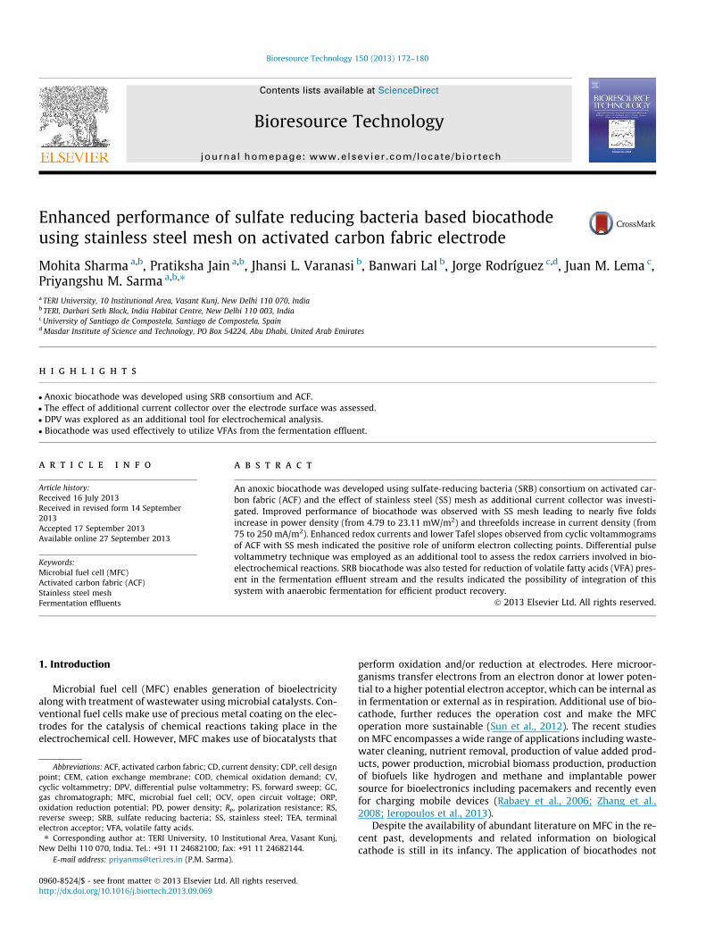
Three conventional H-shape dual-chambered MFCs with total/working volume 200/150 ml were designed and fabricated locallyand cation exchange membrane (CMI-7000; Membranes Interna-tional Inc., USA) was used for partitioning the chambers. The mem-brane was pretreated with 3% sodium chloride overnight and thendried before use as described by Rabaey et al. (2003). The cathodecompartment of the three MFCs consisted of biocathode (as de-scribed above) as electrode while the anode compartment con-sisted of carbon rod electrode pre-treated with dil. sulfuric acid(0.001 M). Both the chambers were sealed using O-rings, clampsand fasteners after purging it with sterile nitrogen gas (SigmaGases and Services, India) and sealed with butyl rubber stoppers.Fig. 1 shows the schematic of the reactor set up used for theexperiments.
Three sets of experiments were conducted simultaneously. Inthe first set of experiment (MFC-1), the biocathode MFC was runin a fed-batch mode with sampling conducted at every 72 h for atotal incubation of 30 days. During sampling, 50 ml of the mediumin the working electrode chamber (cathodic chamber) was replen-ished by fresh medium of API RP-38. In the second set of experi-ment (MFC-2), the ACF electrode material of the biocathode wasembedded onto SS mesh in sterile anaerobic conditions so as tostudy the effect of an additional current collector, while all otheroperating parameters were kept similar to MFC-1. In the third setof experiment (MFC-3), API RP-38 medium was replaced with fer-mentation effluent as electrolyte and the system was operated inbatch mode for 30 days with SS mesh. All the other conditions ofthe reactor configuration and operation remained identical toMFC-2.
2.4. Analytical methods
Out of the total volume of the samples collected for each exper-imental set as described above, 5 ml of sample was centrifuged at10,000 rpm for 10 min and supernatant was filtered and used forpH, ORP and VFA analysis. pH and ORP were measured using apH/ORP meter with relevant probes (SevenMulti pH and conduc-tivity meter, Mettler Toledo, India) as described previously byTenca et al., 2012. VFAs in the liquid phase were analyzed withGC 6890N (Agilent, USA) equipped with flame ionizer detectorand DB-WAXetr column (30 m � 530 lm � 1 lm). The oven
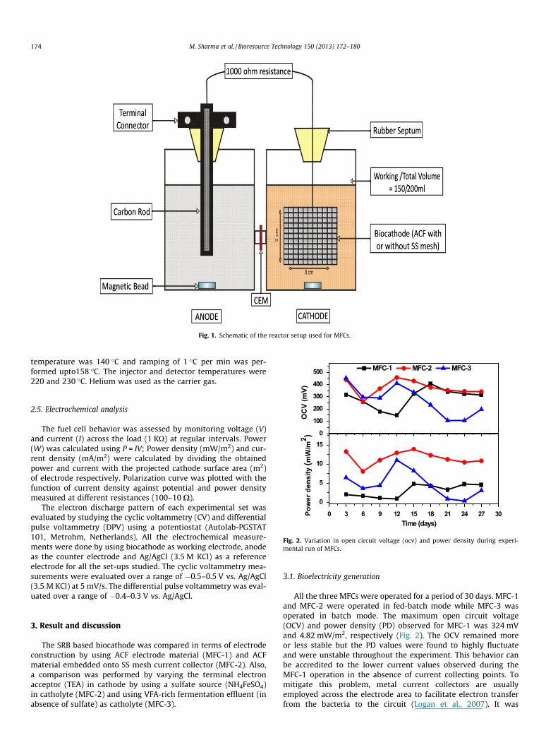
Fig. 1. Schematic of the reactor setup used for MFCs.
400
500
)
MFC-1 MFC-2 MFC-3
174 M. Sharma et al. / Bioresource Technology 150 (2013) 172–180
temperature was 140 �C and ramping of 1 �C per min was per-formed upto158 �C. The injector and detector temperatures were220 and 230 �C. Helium was used as the carrier gas.
0
100
200
300
0 3 6 9 12 15 18 21 24 27 30
0
5
10
15
OC
V (m
VPo
wer
den
sity
(mW
/m2 )
Time (days)
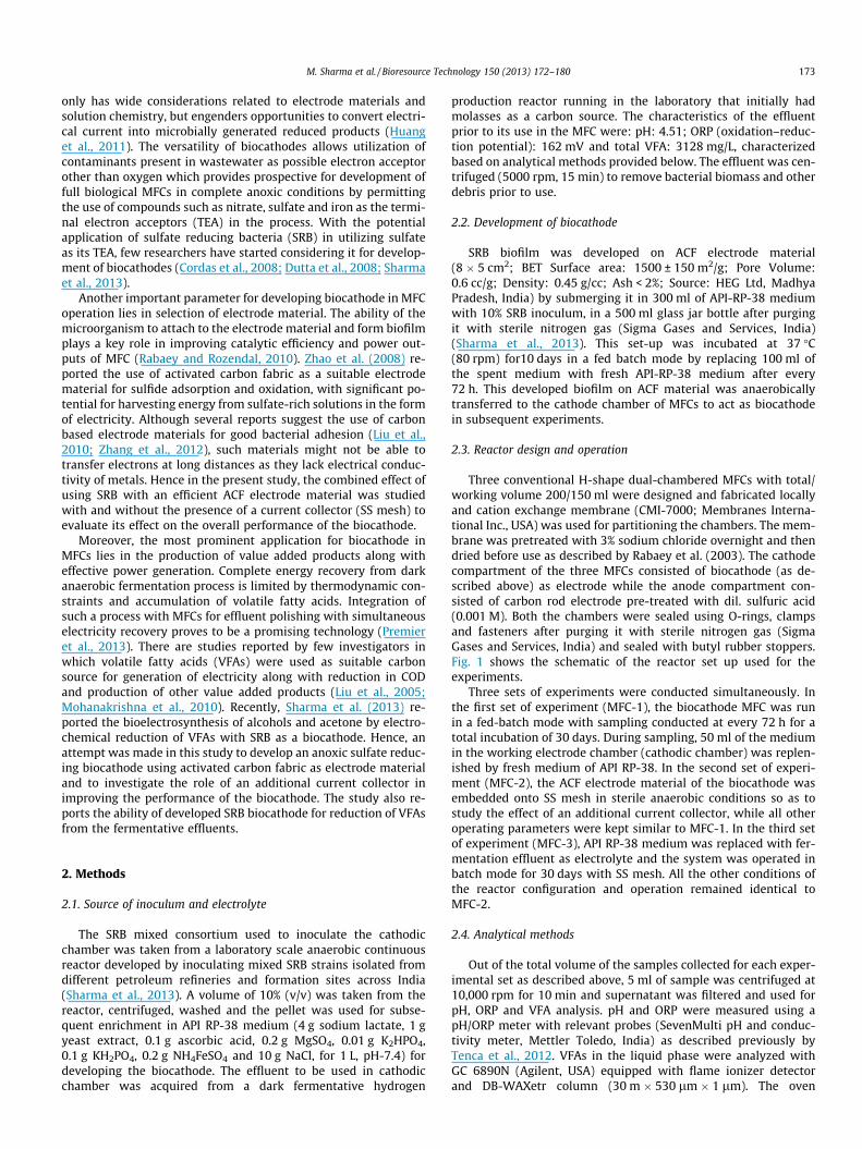
Fig. 2. Variation in open circuit voltage (ocv) and power density during experi-mental run of MFCs.
2.5. Electrochemical analysis
The fuel cell behavior was assessed by monitoring voltage (V)and current (I) across the load (1 KO) at regular intervals. Power(W) was calculated using P = IV; Power density (mW/m2) and cur-rent density (mA/m2) were calculated by dividing the obtainedpower and current with the projected cathode surface area (m2)of electrode respectively. Polarization curve was plotted with thefunction of current density against potential and power densitymeasured at different resistances (100–10 X).
The electron discharge pattern of each experimental set wasevaluated by studying the cyclic voltammetry (CV) and differentialpulse voltammetry (DPV) using a potentiostat (Autolab-PGSTAT101, Metrohm, Netherlands). All the electrochemical measure-ments were done by using biocathode as working electrode, anodeas the counter electrode and Ag/AgCl (3.5 M KCl) as a referenceelectrode for all the set-ups studied. The cyclic voltammetry mea-surements were evaluated over a range of �0.5–0.5 V vs. Ag/AgCl(3.5 M KCl) at 5 mV/s. The differential pulse voltammetry was eval-uated over a range of �0.4–0.3 V vs. Ag/AgCl.
3. Result and discussion
The SRB based biocathode was compared in terms of electrodeconstruction by using ACF electrode material (MFC-1) and ACFmaterial embedded onto SS mesh current collector (MFC-2). Also,a comparison was performed by varying the terminal electronacceptor (TEA) in cathode by using a sulfate source (NH4FeSO4)in catholyte (MFC-2) and using VFA-rich fermentation effluent (inabsence of sulfate) as catholyte (MFC-3).
3.1. Bioelectricity generation
All the three MFCs were operated for a period of 30 days. MFC-1and MFC-2 were operated in fed-batch mode while MFC-3 wasoperated in batch mode. The maximum open circuit voltage(OCV) and power density (PD) observed for MFC-1 was 324 mVand 4.82 mW/m2, respectively (Fig. 2). The OCV remained moreor less stable but the PD values were found to highly fluctuateand were unstable throughout the experiment. This behavior canbe accredited to the lower current values observed during theMFC-1 operation in the absence of current collecting points. Tomitigate this problem, metal current collectors are usuallyemployed across the electrode area to facilitate electron transferfrom the bacteria to the circuit (Logan et al., 2007). It was
M. Sharma et al. / Bioresource Technology 150 (2013) 172–180 175
previously reported that integration of stainless steel (SS) mesh di-rectly to the cathode structure by constructing it around the cath-ode material lead to higher current densities (Zhang et al., 2011). Inthe case of MFC-2, where SS mesh was used as an additional cur-rent collector, a significant increase in OCV and PD value was ob-served with maximum values corresponding to 457 mV and12.98 mW/m2, respectively (Fig. 2). This clearly indicates that useof current collector (SS mesh) had a positive influence on the per-formance of MFC. The three times higher and stable PD observed inthe case of MFC-2, was associated with an equimolar point reduc-tion with the use of SS mesh and also due to reduction in the in-plane resistance across the electrode area, usually caused by thethin films surrounding the surface of the electrode as previouslyreported by Zhang et al. (2011).
Similarly for MFC-3, where the effluent was used as catholyte,the maximum OCV and PD values observed were 406 mV and10.03 mW/m2, respectively which were nearly comparable toMFC-2. However, there was a subsequent drop in both OCV andPD of the system (Fig. 2). This behavior can be attributed to the ab-sence of direct terminal electron acceptor (sulfate) in the cathodechamber. Also, MFC-3 was operated in a batch mode while MFC-2 was operated in a fed-batch mode, which limited the availabilityof suitable electron acceptors during the later stages of operationin MFC-3. Thus the difference in the microenvironment, mode ofoperation and absence of suitable terminal electron acceptor re-sulted in reduced power outputs during later stages in MFC-3(Fig. 2).
3.2. Response to external load
Variation in the electrogenesis in response to the varying exter-nal load was measured and plotted as current density againstpower density and voltage (Venkata Mohan et al., 2010) (Fig. 3).Polarization profiles were adapted to represent the commence-ment of electron discharge along with the cell design point atwhich the fuel cell can be operated effectively. The electron dis-charge was observed from 10 kX for all the three MFCs studied,resulting in perpetual potential drop which continued till the lowerresistance (10 X) reaching near zero values. The current increasedwith decreasing resistance, while the PD reached its maximumvalue at 750 X and decreased thereafter, which corresponds totypical polarization behavior of MFCs. It is a conventional practiceto operate the fuel cell at a high voltage or low current densitybecause the fuel cell becomes unstable at higher current densities
0
200
400
MFC-1
V (mV)
MFC-3
MFC-2
0
10
20PD (mW/m2)
0
200
400
V (mV)
Volta
ge (m
V)
0
10
20
PD (mW/m2)
Power D
ensity (mW
/m2
)
0 50 100 150 200 250 300
0
200
400
V (mV)
Current Density (mA/m2)
0
10
20
PD (mW/m2)
Fig. 3. Polarization-Power density curves recorded at varying resistances (100 kO–10 O) during stable performance of MFCs.
or lower voltages (Mohanakrishna et al., 2010). Resistance at whichmaximum PD (PDmax) is observed is considered as cell design point(CDP). CDP was observed at 750 O for all the three MFCs and hencethis suggests that these biocathode based systems can be operatedat 750 O or higher values under these operational conditions.
Even though for all the MFCs studied, CDP was observed atsame resistance i.e., 750 X, the PD and CD varied considerably.For MFC-1, PDmax was 4.79 mW/m2 reaching maximum CD of75 mA/m2. With MFC-2 the PDmax incremented to 23.11 mW/m2
with a CD of 250 mA/m2. Thus, a substantial increase in CD was ob-served highlighting the positive impact of using SS mesh inimproving the electron transfer by providing a better conductivitythroughout the electrode surface. The power output is also stronglyinfluenced by the structure and composition of the electrolyte used(Liu et al., 2005). For MFC-3, PDmax and CD observed were17.11 mW/m2, and 205 mA/m2, respectively which were nearlycomparable to MFC-2. This suggests that the biocathode was ableto sustain its performance in the presence of the complex catholytei.e., the effluent, indicating that the mixed SRB consortium wasable to utilize effluent as its direct electron acceptor.
3.3. Bioelectrochemical evaluation
Several protons and electrons are generated along with meta-bolic intermediates during substrate metabolism and furtherpumped out, to make power via bacterial membrane bound organ-elles or soluble mediators in a MFC. Bioelectrochemical evaluationhelps to understand the electron discharge as well as the carriersinvolved in the electron transfer (Rabaey et al., 2004). In situ bio-electrochemical evaluation of the three MFC set ups were per-formed at regular intervals (after every 72 h) using cyclicvoltammetry (CV) and differential pulse voltammetry (DPV) tech-nique with an electrochemical work station (Metrohm-Autolab-PGSTAT 101, Netherlands).
3.3.1. CVCV is the principal diagnostic method in electrochemistry and
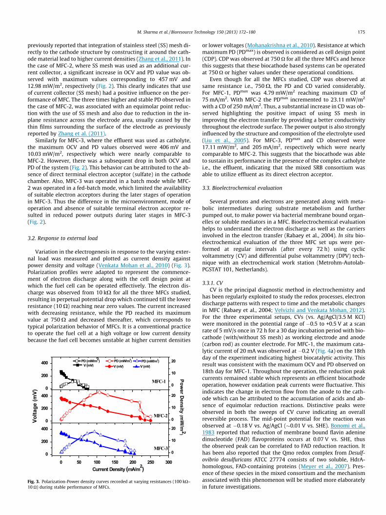
has been regularly exploited to study the redox processes, electrondischarge patterns with respect to time and the metabolic changesin MFC (Rabaey et al., 2004; Velvizhi and Venkata Mohan, 2012).For the three experimental setups, CVs (vs. Ag/AgCl/3.5 M KCl)were monitored in the potential range of �0.5 to +0.5 V at a scanrate of 5 mV/s once in 72 h for a 30 day incubation period with bio-cathode (with/without SS mesh) as working electrode and anode(carbon rod) as counter electrode. For MFC-1, the maximum cata-lytic current of 20 mA was observed at �0.2 V (Fig. 4a) on the 18thday of the experiment indicating highest biocatalytic activity. Thisresult was consistent with the maximum OCV and PD observed on18th day for MFC-1. Throughout the operation, the reduction peakcurrents remained stable which represents an efficient biocathodeoperation, however oxidation peak currents were fluctuative. Thisindicates the change in electron flow from the anode to the cath-ode which can be attributed to the accumulation of acids and ab-sence of equimolar reduction reactions. Distinctive peaks wereobserved in both the sweeps of CV curve indicating an overallreversible process. The mid-point potential for the reaction wasobserved at �0.18 V vs. Ag/AgCl (�0.01 V vs. SHE). Bonomi et al.,1983 reported that reduction of membrane bound flavin adeninedinucleotide (FAD) flavoproteins occurs at 0.07 V vs. SHE, thusthe observed peak can be correlated to FAD reduction reaction. Ithas been also reported that the Qmo redox complex from Desulf-ovibrio desulfuricans ATCC 27774 consists of two soluble, HdrA-homologous, FAD-containing proteins (Meyer et al., 2007). Pres-ence of these species in the mixed consortium and the mechanismassociated with this phenomenon will be studied more elaboratelyin future investigations.
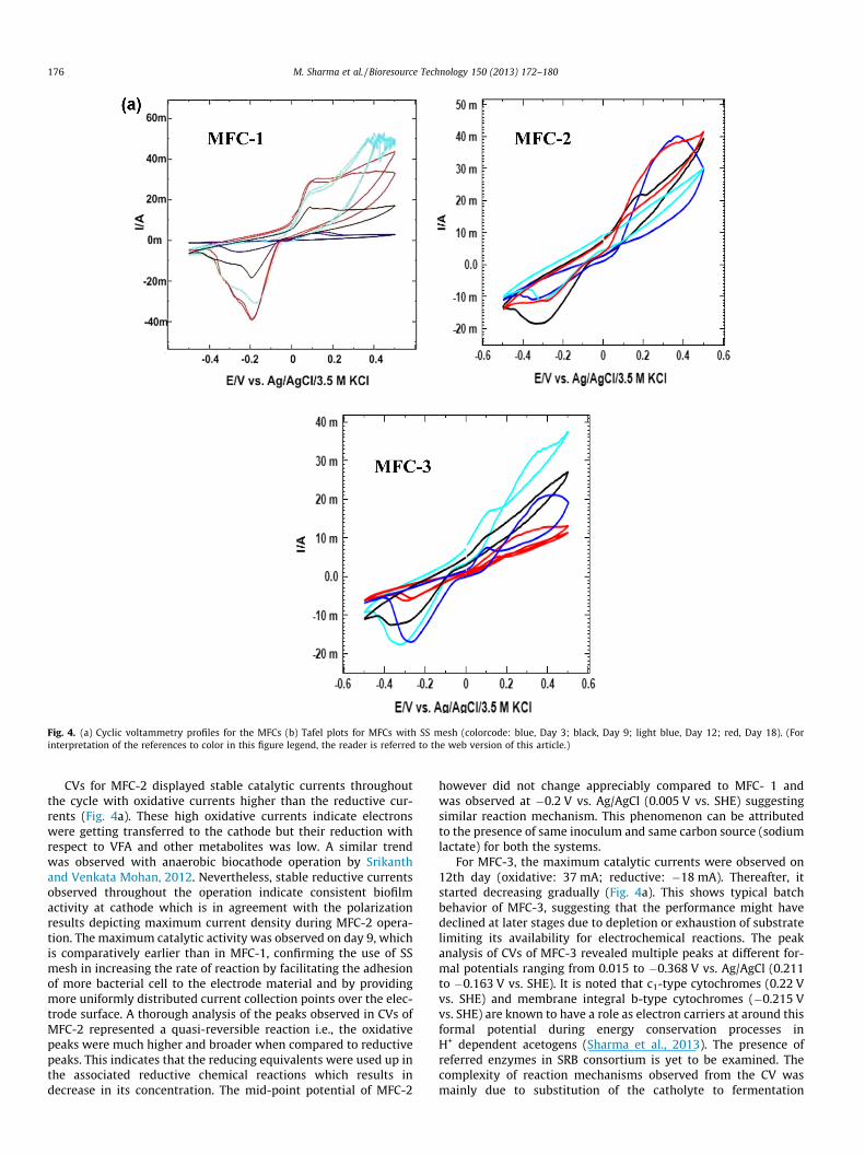
Fig. 4. (a) Cyclic voltammetry profiles for the MFCs (b) Tafel plots for MFCs with SS mesh (colorcode: blue, Day 3; black, Day 9; light blue, Day 12; red, Day 18). (Forinterpretation of the references to color in this figure legend, the reader is referred to the web version of this article.)
176 M. Sharma et al. / Bioresource Technology 150 (2013) 172–180
CVs for MFC-2 displayed stable catalytic currents throughoutthe cycle with oxidative currents higher than the reductive cur-rents (Fig. 4a). These high oxidative currents indicate electronswere getting transferred to the cathode but their reduction withrespect to VFA and other metabolites was low. A similar trendwas observed with anaerobic biocathode operation by Srikanthand Venkata Mohan, 2012. Nevertheless, stable reductive currentsobserved throughout the operation indicate consistent biofilmactivity at cathode which is in agreement with the polarizationresults depicting maximum current density during MFC-2 opera-tion. The maximum catalytic activity was observed on day 9, whichis comparatively earlier than in MFC-1, confirming the use of SSmesh in increasing the rate of reaction by facilitating the adhesionof more bacterial cell to the electrode material and by providingmore uniformly distributed current collection points over the elec-trode surface. A thorough analysis of the peaks observed in CVs ofMFC-2 represented a quasi-reversible reaction i.e., the oxidativepeaks were much higher and broader when compared to reductivepeaks. This indicates that the reducing equivalents were used up inthe associated reductive chemical reactions which results indecrease in its concentration. The mid-point potential of MFC-2
however did not change appreciably compared to MFC- 1 andwas observed at �0.2 V vs. Ag/AgCl (0.005 V vs. SHE) suggestingsimilar reaction mechanism. This phenomenon can be attributedto the presence of same inoculum and same carbon source (sodiumlactate) for both the systems.
For MFC-3, the maximum catalytic currents were observed on12th day (oxidative: 37 mA; reductive: �18 mA). Thereafter, itstarted decreasing gradually (Fig. 4a). This shows typical batchbehavior of MFC-3, suggesting that the performance might havedeclined at later stages due to depletion or exhaustion of substratelimiting its availability for electrochemical reactions. The peakanalysis of CVs of MFC-3 revealed multiple peaks at different for-mal potentials ranging from 0.015 to �0.368 V vs. Ag/AgCl (0.211to �0.163 V vs. SHE). It is noted that c1-type cytochromes (0.22 Vvs. SHE) and membrane integral b-type cytochromes (�0.215 Vvs. SHE) are known to have a role as electron carriers at around thisformal potential during energy conservation processes inH+ dependent acetogens (Sharma et al., 2013). The presence ofreferred enzymes in SRB consortium is yet to be examined. Thecomplexity of reaction mechanisms observed from the CV wasmainly due to substitution of the catholyte to fermentation
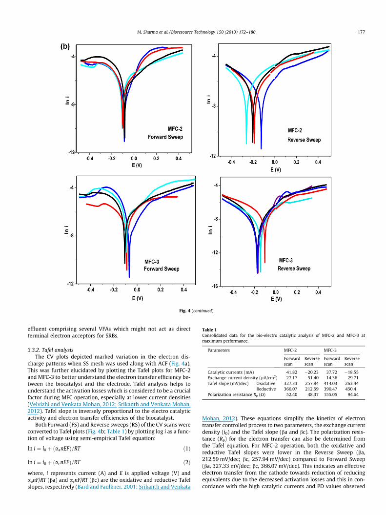
Fig. 4 (continued)
Table 1Consolidated data for the bio-electro catalytic analysis of MFC-2 and MFC-3 atmaximum performance.
Parameters MFC-2 MFC-3
Forwardscan
Reversescan
Forwardscan
Reversescan
Catalytic currents (mA) 41.82 �20.23 37.72 �18.55Exchange current density (lA/cm2) 27.17 51.40 14.36 29.71Tafel slope (mV/dec) Oxidative 327.33 257.94 414.03 263.44
Reductive 366.07 212.59 390.47 450.4Polarization resistance Rp (O) 52.40 48.37 155.05 94.64
M. Sharma et al. / Bioresource Technology 150 (2013) 172–180 177
effluent comprising several VFAs which might not act as directterminal electron acceptors for SRBs.
3.3.2. Tafel analysisThe CV plots depicted marked variation in the electron dis-
charge patterns when SS mesh was used along with ACF (Fig. 4a).This was further elucidated by plotting the Tafel plots for MFC-2and MFC-3 to better understand the electron transfer efficiency be-tween the biocatalyst and the electrode. Tafel analysis helps tounderstand the activation losses which is considered to be a crucialfactor during MFC operation, especially at lower current densities(Velvizhi and Venkata Mohan, 2012; Srikanth and Venkata Mohan,2012). Tafel slope is inversely proportional to the electro catalyticactivity and electron transfer efficiencies of the biocatalyst.
Both Forward (FS) and Reverse sweeps (RS) of the CV scans wereconverted to Tafel plots (Fig. 4b; Table 1) by plotting log i as a func-tion of voltage using semi-empirical Tafel equation:
ln i ¼ i0 þ ðaanEFÞ=RT ð1Þ
ln i ¼ i0 þ ðacnEFÞ=RT ð2Þ
where, i represents current (A) and E is applied voltage (V) andaanF/RT (ba) and acnF/RT (bc) are the oxidative and reductive Tafelslopes, respectively (Bard and Faulkner, 2001; Srikanth and Venkata
Mohan, 2012). These equations simplify the kinetics of electrontransfer controlled process to two parameters, the exchange currentdensity (i0) and the Tafel slope (ba and bc). The polarization resis-tance (Rp) for the electron transfer can also be determined fromthe Tafel equation. For MFC-2 operation, both the oxidative andreductive Tafel slopes were lower in the Reverse Sweep (ba,212.59 mV/dec; bc, 257.94 mV/dec) compared to Forward Sweep(ba, 327.33 mV/dec; bc, 366.07 mV/dec). This indicates an effectiveelectron transfer from the cathode towards reduction of reducingequivalents due to the decreased activation losses and this in con-cordance with the high catalytic currents and PD values observed
178 M. Sharma et al. / Bioresource Technology 150 (2013) 172–180
for MFC-2. Similar observations were made with MFC-3 operationswith lower Tafel slopes during Reverse Sweep (ba, 263.44 mV/dec;bc, 450.4 mV/dec) than in Forward Sweep (ba, 390.07 mV/dec; bc,414.47 mV/dec). However, these values were slightly higher thanin MFC-2 depicting variation in electron transfer efficiency of thebiocatalyst with the type of substrate. The decreased OCV observedduring the later stages of the cycle supports the same observation.The multiple peaks observed in CV plots of MFC-3, clearly indicatethat several complex reactions were taking place in the systemleading to interferences in the electron transfer. Nevertheless, thisdid not affect the overall PD and CD of the system as observed fromthe polarization behavior, and the performance was comparable toMFC-2. This suggests that the SRB based biocathode showed a sus-tained performance even in complex microenvironment. It was de-tected that for both MFC-2 and MFC-3, the observed oxidativeslopes were lower compared to the reductive slopes irrespectiveof the direction of sweep. This indicates higher electron transferefficiency from the biocatalyst to the electrode (Srikanth and Venk-ata Mohan, 2012). The more stabilized reductive currents observedin CVs for both these systems strongly supported the electron avail-ability at the cathode.
Based on the Tafel equation, the Y-axis intercept corresponds tothe logarithm of the exchange current densities (ln i0) and thus theexchange current densities (i0) were calculated at maximum per-formance of the MFCs operations. Exchange current density helpsin determination of electrogenic activity and electron transferacross the electrode. A system with a high exchange current den-sity has fast kinetics and can respond rapidly to a potential change(Srikanth and Venkata Mohan, 2012). In this study, higher ex-change current density was observed during Reverse Sweep overForward Sweep (Table 1), indicating the favorable microenviron-ment for the reduction in MFC-2 and MFC-3. Exchange currentdensities were higher during MFC-2 operation (27.175 lA/cm2
(FS) and 51.4 lA/cm2 (RS) than MFC-3 operation 14.36 lA/cm2
(FS) and 29.718 lA/cm2 (RS) indicating a favorable and controlledreduction microenvironment in the MFC-2, which resulted in sus-tained power generation. The lower current densities of MFC-3 canbe attributed to the presence of certain reducing equivalents thathindered the electron transfer as indicated by the electron dis-charge patterns of MFC-3.
The electron transfer resistances in terms of polarization resis-tance were also calculated from the Tafel slope analysis (Table 1).Similar Rp was observed for both sweeps with MFC-2 operation(48.57 X, FS; 48.37 X, RS) which corresponds to less obstructionin the passage of electrons between the electrode and the biocata-lyst. For MFC-3 operation however, higher Rp was observed duringForward Sweep (155.05 X) than during Reverse Sweep (96.44 X)indicating hindrance in discharge of electrons to the electrode. Thiscan be a result of accumulation of intermediates at the electrodesurface and occurrence of other side reactions, which limits theavailability of electroactive surface over the electrode by obstruct-ing efficient electron transfer.
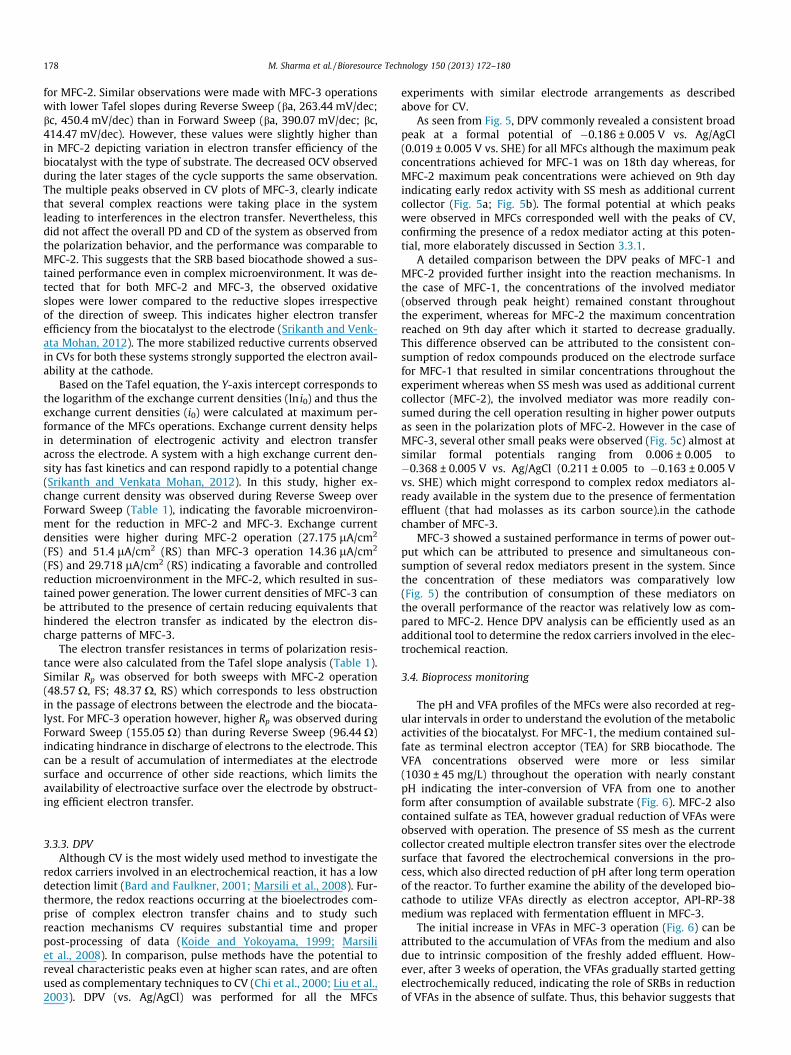
3.3.3. DPVAlthough CV is the most widely used method to investigate the
redox carriers involved in an electrochemical reaction, it has a lowdetection limit (Bard and Faulkner, 2001; Marsili et al., 2008). Fur-thermore, the redox reactions occurring at the bioelectrodes com-prise of complex electron transfer chains and to study suchreaction mechanisms CV requires substantial time and properpost-processing of data (Koide and Yokoyama, 1999; Marsiliet al., 2008). In comparison, pulse methods have the potential toreveal characteristic peaks even at higher scan rates, and are oftenused as complementary techniques to CV (Chi et al., 2000; Liu et al.,2003). DPV (vs. Ag/AgCl) was performed for all the MFCs
experiments with similar electrode arrangements as describedabove for CV.
As seen from Fig. 5, DPV commonly revealed a consistent broadpeak at a formal potential of �0.186 ± 0.005 V vs. Ag/AgCl(0.019 ± 0.005 V vs. SHE) for all MFCs although the maximum peakconcentrations achieved for MFC-1 was on 18th day whereas, forMFC-2 maximum peak concentrations were achieved on 9th dayindicating early redox activity with SS mesh as additional currentcollector (Fig. 5a; Fig. 5b). The formal potential at which peakswere observed in MFCs corresponded well with the peaks of CV,confirming the presence of a redox mediator acting at this poten-tial, more elaborately discussed in Section 3.3.1.
A detailed comparison between the DPV peaks of MFC-1 andMFC-2 provided further insight into the reaction mechanisms. Inthe case of MFC-1, the concentrations of the involved mediator(observed through peak height) remained constant throughoutthe experiment, whereas for MFC-2 the maximum concentrationreached on 9th day after which it started to decrease gradually.This difference observed can be attributed to the consistent con-sumption of redox compounds produced on the electrode surfacefor MFC-1 that resulted in similar concentrations throughout theexperiment whereas when SS mesh was used as additional currentcollector (MFC-2), the involved mediator was more readily con-sumed during the cell operation resulting in higher power outputsas seen in the polarization plots of MFC-2. However in the case ofMFC-3, several other small peaks were observed (Fig. 5c) almost atsimilar formal potentials ranging from 0.006 ± 0.005 to�0.368 ± 0.005 V vs. Ag/AgCl (0.211 ± 0.005 to �0.163 ± 0.005 Vvs. SHE) which might correspond to complex redox mediators al-ready available in the system due to the presence of fermentationeffluent (that had molasses as its carbon source).in the cathodechamber of MFC-3.
MFC-3 showed a sustained performance in terms of power out-put which can be attributed to presence and simultaneous con-sumption of several redox mediators present in the system. Sincethe concentration of these mediators was comparatively low(Fig. 5) the contribution of consumption of these mediators onthe overall performance of the reactor was relatively low as com-pared to MFC-2. Hence DPV analysis can be efficiently used as anadditional tool to determine the redox carriers involved in the elec-trochemical reaction.
3.4. Bioprocess monitoring
The pH and VFA profiles of the MFCs were also recorded at reg-ular intervals in order to understand the evolution of the metabolicactivities of the biocatalyst. For MFC-1, the medium contained sul-fate as terminal electron acceptor (TEA) for SRB biocathode. TheVFA concentrations observed were more or less similar(1030 ± 45 mg/L) throughout the operation with nearly constantpH indicating the inter-conversion of VFA from one to anotherform after consumption of available substrate (Fig. 6). MFC-2 alsocontained sulfate as TEA, however gradual reduction of VFAs wereobserved with operation. The presence of SS mesh as the currentcollector created multiple electron transfer sites over the electrodesurface that favored the electrochemical conversions in the pro-cess, which also directed reduction of pH after long term operationof the reactor. To further examine the ability of the developed bio-cathode to utilize VFAs directly as electron acceptor, API-RP-38medium was replaced with fermentation effluent in MFC-3.
The initial increase in VFAs in MFC-3 operation (Fig. 6) can beattributed to the accumulation of VFAs from the medium and alsodue to intrinsic composition of the freshly added effluent. How-ever, after 3 weeks of operation, the VFAs gradually started gettingelectrochemically reduced, indicating the role of SRBs in reductionof VFAs in the absence of sulfate. Thus, this behavior suggests that
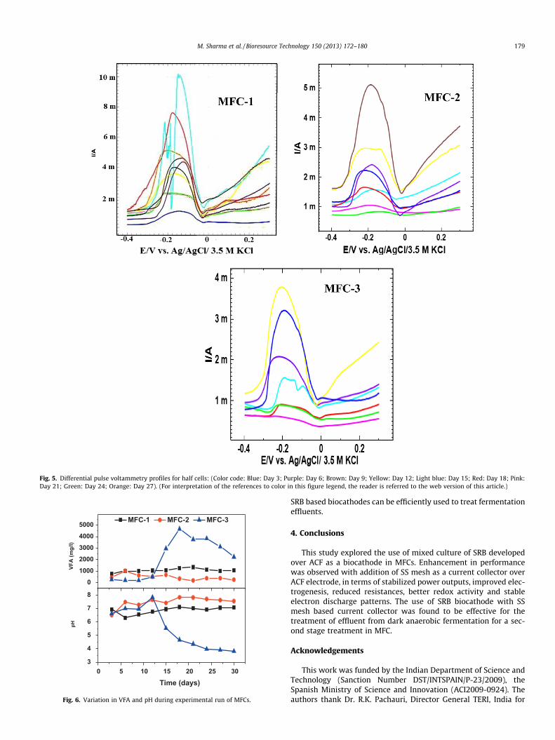
Fig. 5. Differential pulse voltammetry profiles for half cells: (Color code: Blue: Day 3; Purple: Day 6; Brown: Day 9; Yellow: Day 12; Light blue: Day 15; Red: Day 18; Pink:Day 21; Green: Day 24; Orange: Day 27). (For interpretation of the references to color in this figure legend, the reader is referred to the web version of this article.)
010002000300040005000
0 5 10 15 20 25 303
4
5
6
7
8
VFA
(mg/
l)
MFC-1 MFC-2 MFC-3
pH
Time (days)
Fig. 6. Variation in VFA and pH during experimental run of MFCs.
M. Sharma et al. / Bioresource Technology 150 (2013) 172–180 179
SRB based biocathodes can be efficiently used to treat fermentationeffluents.
4. Conclusions
This study explored the use of mixed culture of SRB developedover ACF as a biocathode in MFCs. Enhancement in performancewas observed with addition of SS mesh as a current collector overACF electrode, in terms of stabilized power outputs, improved elec-trogenesis, reduced resistances, better redox activity and stableelectron discharge patterns. The use of SRB biocathode with SSmesh based current collector was found to be effective for thetreatment of effluent from dark anaerobic fermentation for a sec-ond stage treatment in MFC.
Acknowledgements
This work was funded by the Indian Department of Science andTechnology (Sanction Number DST/INTSPAIN/P-23/2009), theSpanish Ministry of Science and Innovation (ACI2009-0924). Theauthors thank Dr. R.K. Pachauri, Director General TERI, India for
180 M. Sharma et al. / Bioresource Technology 150 (2013) 172–180
providing excellent infrastructure and research facility. Theauthors are also grateful to Dr. P. Dureja (TERI, India) and Dr. K. Ra-baey (Ghent University, Belgium) for their technical guidance andDr. D. Pant (VITO, Belgium) and Dr. S. Sandipam (VITO, Belgium)for helpful discussions.
References
Bard, A.J., Faulkner, L.R., 2001. Electrochemical Methods. Wiley, New York, NY.Bonomi, F., Pagani, S., Cerletti, P., Giori, C., 1983. Modification of the thermodynamic
properties of the electron-transferring groups in mitochondrial succinatedehydrogenase upon binding of succinate. Eur. J. Biochem. 134, 439–445.
Chi, Q., Zhang, J., Nielsen, J.U., Friis, E.P., Chorkendorff, I., Canters, G.W., Andersen,J.E.T., Ulstrup, J., 2000. Molecular monolayers and interfacial electron transfer ofPseudomonas aeruginosa azurin on Au (111). J. Am. Chem. Soc. 122, 4047–4055.
Cordas, C.M., Guerra, L.T., Xavier, C., Moura, J.J., 2008. Electroactive biofilms ofsulphate reducing bacteria. Electrochim. Acta 54, 29–34.
Dutta, P.K., Rabaey, K., Yuan, Z., Keller, J.R., 2008. Spontaneous electrochemicalremoval of aqueous sulfide. Water Res. 42, 4965–4975.
Huang, L., Regan, J.M., Quan, X., 2011. Electron transfer mechanisms, newapplications, and performance of biocathode microbial fuel cells. Bioresour.Technol. 102, 316–323.
Ieropoulos, I., Ledezma, P., Stinchcombe, A., Papaharalabos, G., Melhuish, C.,Greenman, J., 2013. Waste to real energy: the first MFC powered mobilephone. Phys. Chem. Chem. Phys. 15, 15312–15316.
Koide, S., Yokoyama, K., 1999. Electrochemical characterization of an enzymeelectrode based on a ferrocene-containing redox polymer. J. Electroanal. Chem.468, 193–201.
Liu, H.H., Lu, J.L., Zhang, M., Pang, D.W., Abruna, H.D., 2003. Direct electrochemistryof cytochrome c surface confined on DNA-modified gold electrodes. J.Electroanal. Chem. 544, 93–100.
Liu, H., Cheng, S., Logan, B.E., 2005. Production of electricity from acetate or butyrateusing a single-chamber microbial fuel cell. Environ. Sci. Technol. 39, 658–662.
Liu, Y., Harnisch, F., Fricke, K., Schröder, U., Climent, V., Feliu, J.M., 2010. The study ofelectrochemically active microbial biofilms on different carbon-based anodematerials in microbial fuel cells. Biosens. Bioelectron. 25, 2167–2171.
Logan, B.E., 2010. Scaling up microbial fuel cells and other bioelectrochemicalsystems. Appl. Microbiol. Biotechnol. 85, 1665–1671.
Logan, B., Cheng, S., Watson, V., Estadt, G., 2007. Graphite fiber brush anodes forincreased power production in air–cathode microbial fuel cells. Environ. Sci.Technol. 41, 3341–3346.
Marsili, E., Rollefson, J.B., Baron, D.B., Hozalski, R.M., Bond, D.R., 2008. Microbialbiofilm voltammetry: direct electrochemical characterization of catalyticelectrode-attached biofilms. Appl. Environ. Microbiol. 74, 7329–7337.
Meyer, B., Kuever, J., 2007. Phylogeny of the alpha and beta subunits of thedissimilatory adenosine-50-phosphosulfate (APS) reductase from sulfate-
reducing prokaryotes – origin and evolution of the dissimilatory sulfate-reduction pathway. Microbiology 153, 2026–2044 (Reading, England).
Mohanakrishna, G., Venkata Mohan, S., Sarma, P.N., 2010. Utilizing acid-richeffluents of fermentative hydrogen production process as substrate forharnessing bioelectricity: an integrative approach. Int. J. Hydrogen Energy 35,3440–3449.
Premier, G.C., Kim, J.R., Massanet-nicolau, J., Kyazze, G., Esteves, S.R.R., 2013.Integration of biohydrogen, biomethane and bioelectrochemical systems.Renewable Energy 49, 188–192.
Rabaey, K., Rozendal, R.A., 2010. Microbial electrosynthesis – revisiting theelectrical route for microbial production. Nat. Rev. Microbiol. 8, 706–716.
Rabaey, K., Sompel, K.V.D., Maignien, L., Boon, N., Aelterman, P., Clauwaert, P.,Schamphelaire, L.D., Pham, H.T., Vermeulen, J., Verhaege, M., Lens, P., Verstraete,W., 2006. Microbial fuel cells for sulfide removal. Environ. Sci. Technol. 40,5218–5224.
Sharma, M., Aryal, N., Sarma, P.M., Vanbroekhoven, K., Lal, B., Dominguez-Benetton,X., Pant, D., 2013. Bioelectrocatalyzed reduction of acetic and butyric acids viadirect electron transfer by a mixed culture of sulfate-reducers driveselectrosynthesis of alcohols and acetone. Chem. Commun. 49, 6495–6497.
Srikanth, S., Venkata Mohan, S., 2012. Change in electrogenic activity of themicrobial fuel cell (MFC) with the function of biocathode microenvironment asterminal electron accepting condition: influence on overpotentials and bio-electro kinetics. Bioresour. Technol. 119, 241–251.
Sun, Y., Wei, J., Liang, P., Huang, X., 2012. Microbial community analysis inbiocathode microbial fuel cells packed with different materials. AMB Express 2,1–8.
Tenca, A., Cusick, R.D., Schievano, A., Oberti, R., Logan, B.E., 2012. Evaluation of lowcost cathode materials for treatment of industrial and food processingwastewater using microbial electrolysis cells. Int. J. Hydrogen Energy 38,1859–1865.
Velvizhi, G., Venkata Mohan, S., 2012. Electrogenic activity and electron lossesunder increasing organic load of recalcitrant pharmaceutical wastewater. Int. J.Hydrogen Energy 37, 5969–5978.
Venkata Mohan, S., Mohanakrishna, G., Velvizhi, G., Babu, V.L., Sarma, P.N., 2010.Bio-catalyzed electrochemical treatment of real field dairy wastewater withsimultaneous power generation. Biochem. Eng. J. 51, 32–39.
Zhang, J.N., Zhao, Q.L., Aelterman, P., You, S.J., Jiang, J.Q., 2008. Electricity generationin a microbial fuel cell with a microbially catalyzed cathode. Biotechnol. Lett.30, 1771–1776.
Zhang, F., Merrill, M.D., Tokash, J.C., Saito, T., Cheng, S., Hickner, M.A., Logan, B.E.,2011. Mesh optimization for microbial fuel cell cathodes constructed aroundstainless steel mesh current collectors. J. Power Sources 196, 1097–1102.
Zhang, Y., Sun, J., Hu, Y., Li, S., Xu, Q., 2012. Bio-cathode materials evaluation inmicrobial fuel cells: a comparison of graphite felt, carbon paper and stainlesssteel mesh materials. Int. J. Hydrogen Energy 37, 16935–16942.
Zhao, F., Rahunen, N., Varcoe, J.R., Chandra, A., Avignone-Rossa, C., Thumser, A.E.,Slade, R.C., 2008. Activated carbon cloth as anode for sulphate removal in amicrobial fuel cell. Environ. Sci. Technol. 42, 4971–4976.
Related Documents


