Page 1 BES468878 Enhance Rebar detailing with Revit and Graitec Powerpack Stevens CHEMISE GRAITEC Innovation Daniel GHEORGHE GRAITEC Romania Description In this class, you will discover a set of effective tools to address rebar detailing topics within Revit using the PowerPack add-on. First, you will measure added value of using wizard for 3D cage generation, applied for usual linear elements such as beams, columns and footings, respecting common constructive disposal rules. Complementary tools to manage rebars during creation phase will be presented such as controlling rebar visibility or manipulating bars (trim, extend, copy or split bars…). Then, standards reinforcement will be completed with additional bars placed around openings and edges for planar elements (walls and slabs). Automatic schedules will be created thanks to flexible and configurable templates. To conclude, reinforcement drawings will be generated with specific commands, assisting users to choose right tittle blocks, to place views or schedules in final sheets. Drawings will be tuned with bending details, automatic schemas completing schedules and end bar symbol. Learning Objectives • Generate parametric rebar cages for RC members, including automatic constructive disposals. • Stop wasting time generating bars and fabrics schedules and get quantity takeoff in few clicks! • Rebar objects handling in your Revit Model: split, trim, extend, copy rebar… • Custom and tune final rebar drawings with dedicated detailing tools.

Welcome message from author
This document is posted to help you gain knowledge. Please leave a comment to let me know what you think about it! Share it to your friends and learn new things together.
Transcript
Page 1
BES468878
Enhance Rebar detailing with Revit and Graitec Powerpack Stevens CHEMISE GRAITEC Innovation
Daniel GHEORGHE GRAITEC Romania
Description
In this class, you will discover a set of effective tools to address rebar detailing topics within Revit using the PowerPack add-on.
First, you will measure added value of using wizard for 3D cage generation, applied for usual linear elements such as beams, columns and footings, respecting common constructive disposal rules. Complementary tools to manage rebars during creation phase will be presented such as controlling rebar visibility or manipulating bars (trim, extend, copy or split bars…).
Then, standards reinforcement will be completed with additional bars placed around openings and edges for planar elements (walls and slabs). Automatic schedules will be created thanks to flexible and configurable templates.
To conclude, reinforcement drawings will be generated with specific commands, assisting users to choose right tittle blocks, to place views or schedules in final sheets. Drawings will be tuned with bending details, automatic schemas completing schedules and end bar symbol.
Learning Objectives
• Generate parametric rebar cages for RC members, including automatic constructive disposals.
• Stop wasting time generating bars and fabrics schedules and get quantity takeoff in few clicks!
• Rebar objects handling in your Revit Model: split, trim, extend, copy rebar…
• Custom and tune final rebar drawings with dedicated detailing tools.

Page 2
Speaker(s)
Stevens CHEMISE has the position of BIM Industry Manager at Graitec Innovation , part of the Graitec Product Management Team He has a Structural Enginering Background and 15 Years experience in several BIM Software companies. With main technical expertise on Revit, Navisworks, BIM 360, he closely works with for Architects or structural engineer to improve workflow between Autodesk products and Graitec design software. He’s the co-author of a books available in France and Italy for learning Revit concepts: Revit pour le BIM , Revit per il BIM Daniel GHEORGHE is a Structural Engineer, working as Technical solutions consultant at Graitec Romania. Part of the R&D and Sales departments with 7 years experience on Revit Structure , he’s Certified Professional and ATC Instructor. He use his structural engineering experience to develop and improve our solutions. Proficient with BIM 360, Dynamo for Revit, Advance Steel, Navisworks.

Page 3
General
User Interface The GRAITEC PowerPack provides a broad suite of unique commands and functionality to significantly increase productivity when working with Autodesk® Revit®. To make it easier to find commands typical for different GRAITEC PowerPack package configurations, changes have been made to the distribution of commands. Three ribbons are now available: On the PowerPack ribbon, users can find multidisciplinary commands for all revit users ( Architects, structural, MEP...).
On the PowerPack Detailing ribbon, users can find commands for creating parametric 3D rebar cages, for automating the creation of rebar views, 2D rebar bending details and lists with bending schedules, as available in the Rebar Detailing package.
On the PowerPack Design ribbon, users can find commands for designing rebar cages according to international design codes, as available in the Rebar Designing and Detailing package.
Figures
Page 4
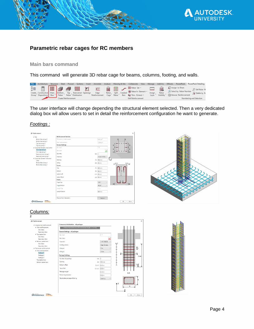
Parametric rebar cages for RC members
Main bars command This command will generate 3D rebar cage for beams, columns, footing, and walls.
The user interface will change depending the structural element selected. Then a very dedicated dialog box wil allow users to set in detail the reinforcement configuration he want to generate. Footings :
Columns: ²
Page 5
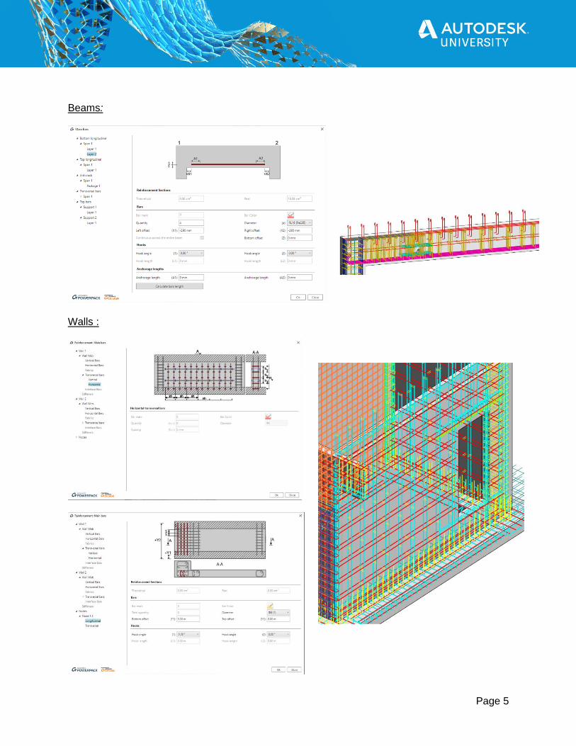
Beams:
Walls :
Page 6
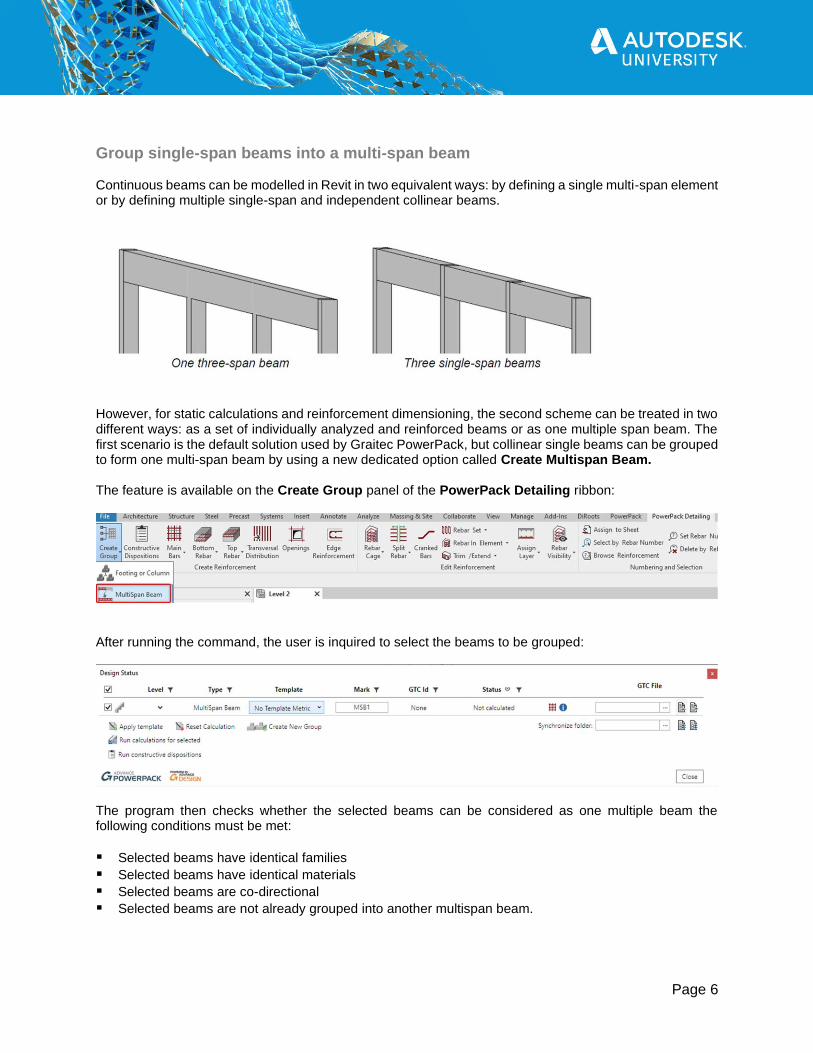
Group single-span beams into a multi-span beam Continuous beams can be modelled in Revit in two equivalent ways: by defining a single multi-span element or by defining multiple single-span and independent collinear beams.
However, for static calculations and reinforcement dimensioning, the second scheme can be treated in two different ways: as a set of individually analyzed and reinforced beams or as one multiple span beam. The first scenario is the default solution used by Graitec PowerPack, but collinear single beams can be grouped to form one multi-span beam by using a new dedicated option called Create Multispan Beam. The feature is available on the Create Group panel of the PowerPack Detailing ribbon:
After running the command, the user is inquired to select the beams to be grouped:
The program then checks whether the selected beams can be considered as one multiple beam the following conditions must be met:
▪ Selected beams have identical families
▪ Selected beams have identical materials
▪ Selected beams are co-directional
▪ Selected beams are not already grouped into another multispan beam.
Page 7
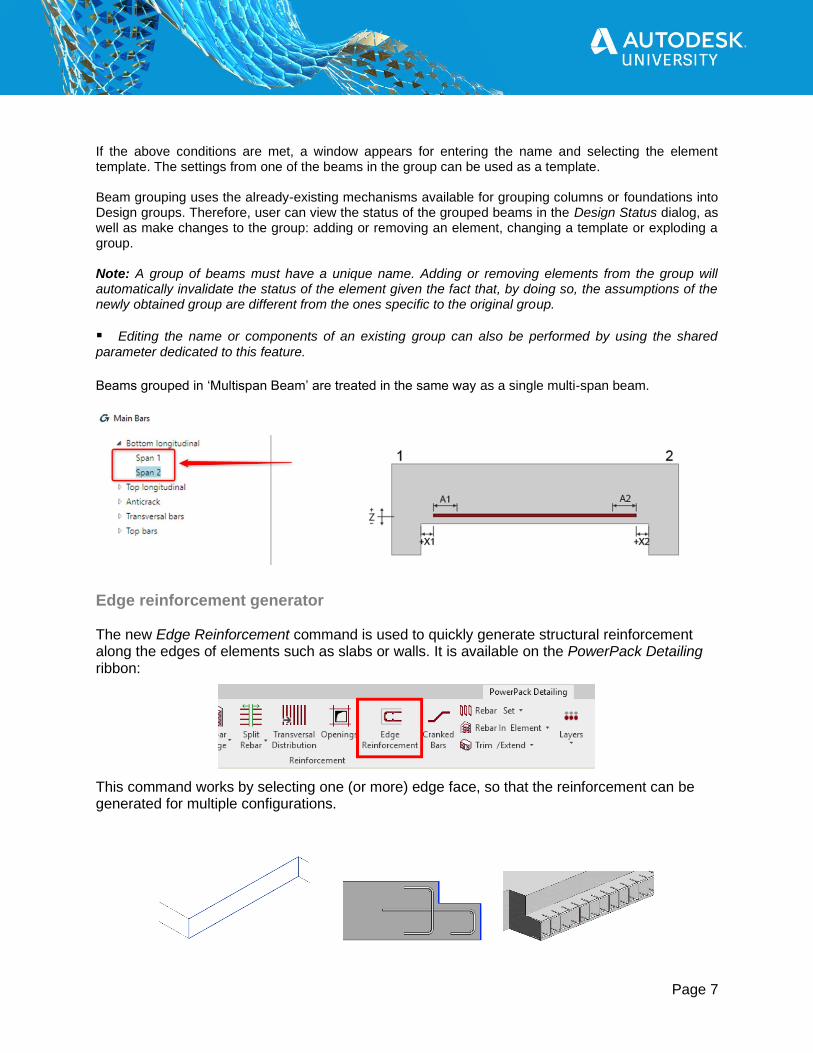
If the above conditions are met, a window appears for entering the name and selecting the element template. The settings from one of the beams in the group can be used as a template. Beam grouping uses the already-existing mechanisms available for grouping columns or foundations into Design groups. Therefore, user can view the status of the grouped beams in the Design Status dialog, as well as make changes to the group: adding or removing an element, changing a template or exploding a group. Note: A group of beams must have a unique name. Adding or removing elements from the group will automatically invalidate the status of the element given the fact that, by doing so, the assumptions of the newly obtained group are different from the ones specific to the original group.
▪ Editing the name or components of an existing group can also be performed by using the shared
parameter dedicated to this feature.
Beams grouped in ‘Multispan Beam’ are treated in the same way as a single multi-span beam.
Edge reinforcement generator The new Edge Reinforcement command is used to quickly generate structural reinforcement along the edges of elements such as slabs or walls. It is available on the PowerPack Detailing ribbon:
This command works by selecting one (or more) edge face, so that the reinforcement can be generated for multiple configurations.

Page 8
The configuration window allows the setting of parameters for:
➢ transverse reinforcement (open or closed)
➢ and longitudinal bars, separately for vertical, top and bottom distributions.
The available settings allow for many different layout configurations, for example:
Page 9
Reinforcement around openings
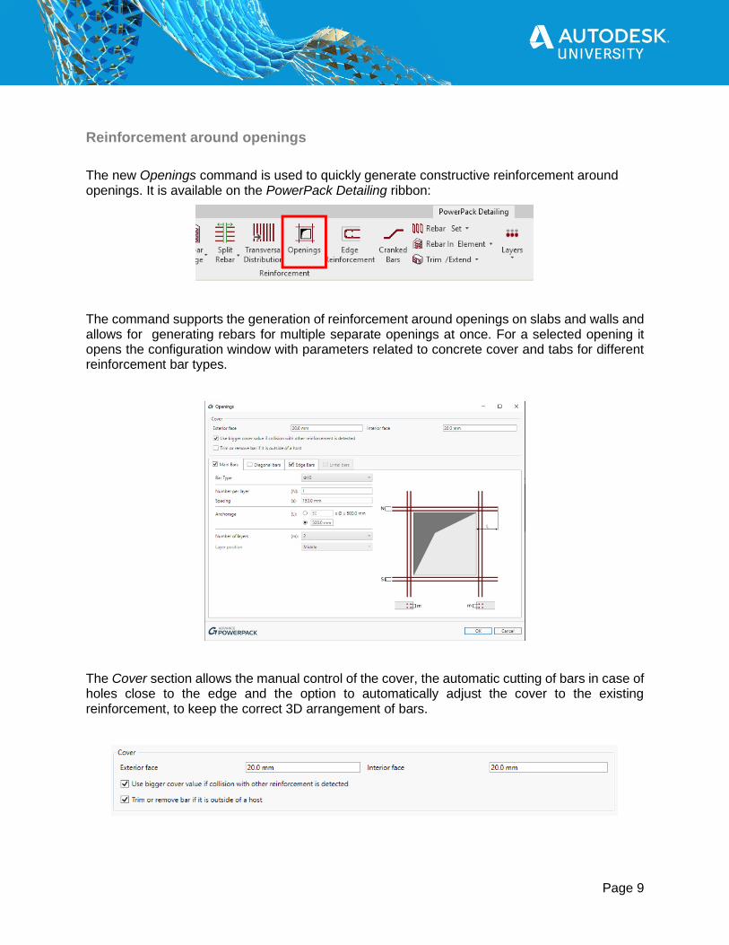
The new Openings command is used to quickly generate constructive reinforcement around openings. It is available on the PowerPack Detailing ribbon:
The command supports the generation of reinforcement around openings on slabs and walls and allows for generating rebars for multiple separate openings at once. For a selected opening it opens the configuration window with parameters related to concrete cover and tabs for different reinforcement bar types.
The Cover section allows the manual control of the cover, the automatic cutting of bars in case of holes close to the edge and the option to automatically adjust the cover to the existing reinforcement, to keep the correct 3D arrangement of bars.

Page 10
The remaining parameters are available on independent tabs separately for four optional reinforcement types: Main bars (longitudinal bars along edges), Diagonal bars (bars that are perpendicular to bisectors of corners), Edge bars (transverse bars along edges) and Lintel bars (longitudinal and transversal bars above openings on walls). Thanks to the wide range of settings, many different bar configurations are possible.

Page 11
In the case of nonrectangular shapes of openings, the reinforcement is generated on its rectangular external perimeter
Page 12
Generate bars and fabrics schedules
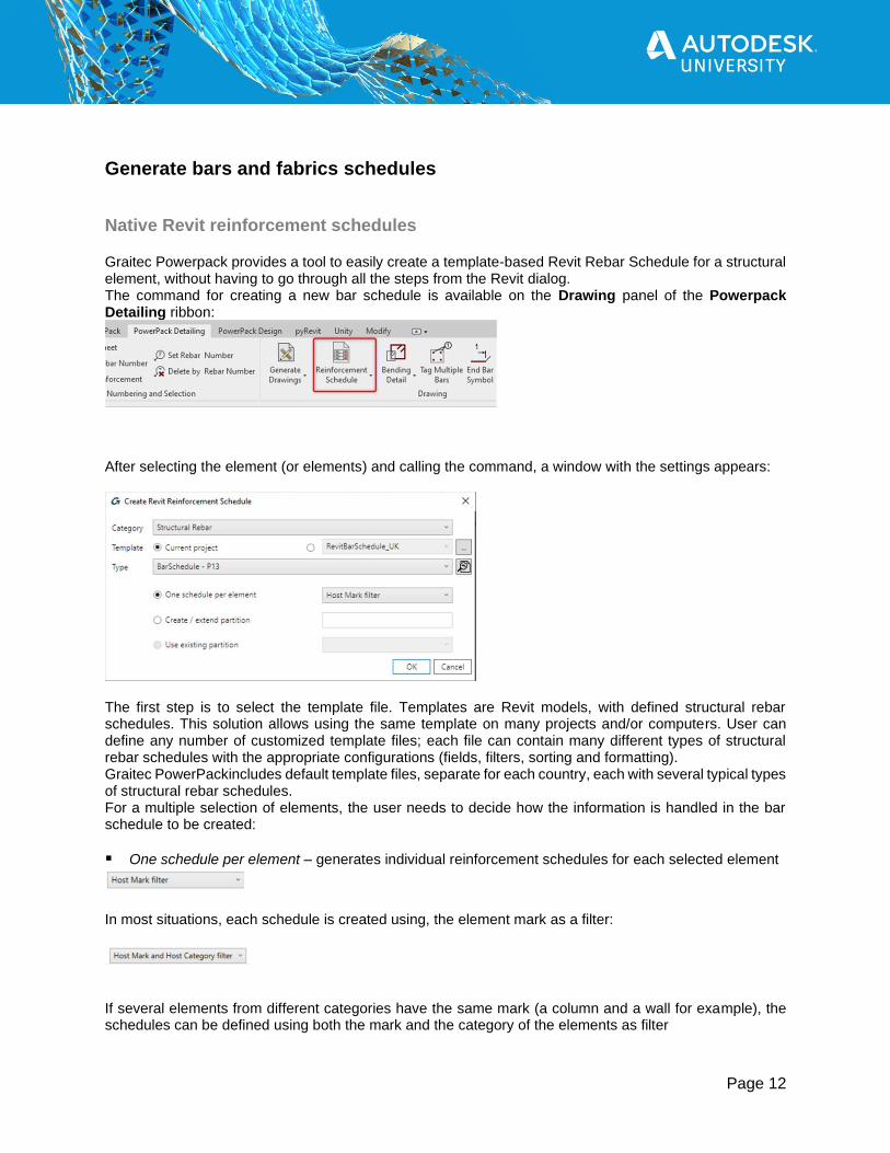
Native Revit reinforcement schedules Graitec Powerpack provides a tool to easily create a template-based Revit Rebar Schedule for a structural element, without having to go through all the steps from the Revit dialog. The command for creating a new bar schedule is available on the Drawing panel of the Powerpack Detailing ribbon:
After selecting the element (or elements) and calling the command, a window with the settings appears:
The first step is to select the template file. Templates are Revit models, with defined structural rebar schedules. This solution allows using the same template on many projects and/or computers. User can define any number of customized template files; each file can contain many different types of structural rebar schedules with the appropriate configurations (fields, filters, sorting and formatting). Graitec PowerPackincludes default template files, separate for each country, each with several typical types of structural rebar schedules. For a multiple selection of elements, the user needs to decide how the information is handled in the bar schedule to be created:
▪ One schedule per element – generates individual reinforcement schedules for each selected element
In most situations, each schedule is created using, the element mark as a filter:
If several elements from different categories have the same mark (a column and a wall for example), the schedules can be defined using both the mark and the category of the elements as filter
Page 13
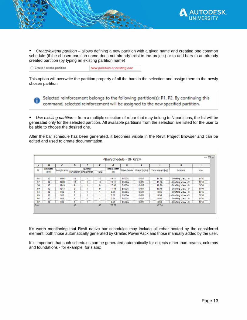
▪ Create/extend partition – allows defining a new partition with a given name and creating one common
schedule (if the chosen partition name does not already exist in the project) or to add bars to an already created partition (by typing an existing partition name)
This option will overwrite the partition property of all the bars in the selection and assign them to the newly chosen partition
▪ Use existing partition – from a multiple selection of rebar that may belong to N partitions, the list will be
generated only for the selected partition. All available partitions from the selection are listed for the user to be able to choose the desired one. After the bar schedule has been generated, it becomes visible in the Revit Project Browser and can be edited and used to create documentation.
It’s worth mentioning that Revit native bar schedules may include all rebar hosted by the considered element, both those automatically generated by Graitec PowerPack and those manually added by the user. It is important that such schedules can be generated automatically for objects other than beams, columns and foundations - for example, for slabs:
Page 14
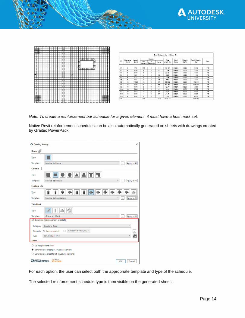
Note: To create a reinforcement bar schedule for a given element, it must have a host mark set. Native Revit reinforcement schedules can be also automatically generated on sheets with drawings created by Graitec PowerPack.
For each option, the user can select both the appropriate template and type of the schedule. The selected reinforcement schedule type is then visible on the generated sheet:
Page 15
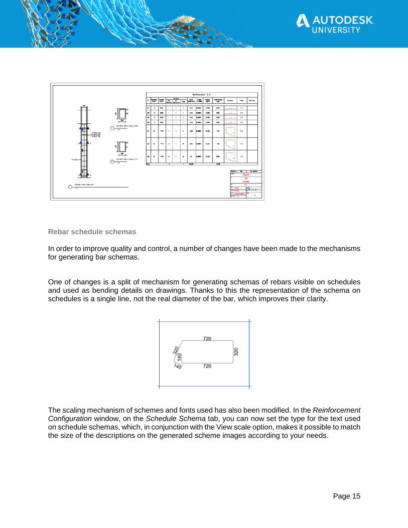
Rebar schedule schemas In order to improve quality and control, a number of changes have been made to the mechanisms for generating bar schemas.
One of changes is a split of mechanism for generating schemas of rebars visible on schedules and used as bending details on drawings. Thanks to this the representation of the schema on schedules is a single line, not the real diameter of the bar, which improves their clarity.
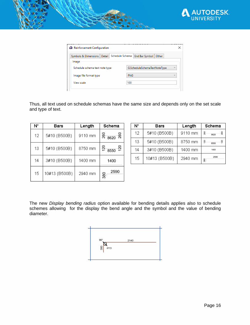
The scaling mechanism of schemes and fonts used has also been modified. In the Reinforcement Configuration window, on the Schedule Schema tab, you can now set the type for the text used on schedule schemas, which, in conjunction with the View scale option, makes it possible to match the size of the descriptions on the generated scheme images according to your needs.
Page 16
Thus, all text used on schedule schemas have the same size and depends only on the set scale and type of text.
The new Display bending radius option available for bending details applies also to schedule schemes allowing for the display the bend angle and the symbol and the value of bending diameter.

Page 17
Rebar objects handling in your Revit Model
Split Rebar
Split rebar functionality allows for dividing existing reinforcement bars with the use of multiple possible rules, including maintaining the continuity of the divided bars.
There are three commands available allowing three modes of splitting:
• Split Rebar – it is an automatic mode for splicing straight bars (with/without hooks) defined as single or in a set (including regular and varying length set type), respecting a set of rules and different connection methods.
• Split at Line – it is a manual mode available only on 2D view that divides rebars (single or in a set) by using earlier defined lines.
• Split at Element – This is a new feature, dedicated to split rebar distribution by selecting a structural element which will be the dividing element. In the following example, a beam was selected to cut all longitudinal rebars.

Page 18
The Split Rebar commands opens a configuration dialog that contains settings for selecting either a splitting method or a connection method; the preview is based on real geometry and offers the possibility to edit the lengths of divided bars.
Page 19
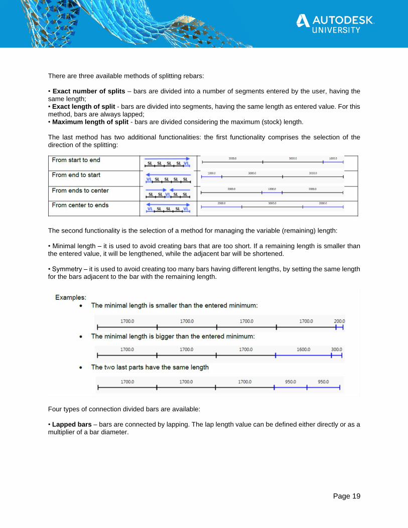
There are three available methods of splitting rebars: • Exact number of splits – bars are divided into a number of segments entered by the user, having the same length; • Exact length of split - bars are divided into segments, having the same length as entered value. For this method, bars are always lapped; • Maximum length of split - bars are divided considering the maximum (stock) length. The last method has two additional functionalities: the first functionality comprises the selection of the direction of the splitting:
The second functionality is the selection of a method for managing the variable (remaining) length: • Minimal length – it is used to avoid creating bars that are too short. If a remaining length is smaller than the entered value, it will be lengthened, while the adjacent bar will be shortened. • Symmetry – it is used to avoid creating too many bars having different lengths, by setting the same length for the bars adjacent to the bar with the remaining length.
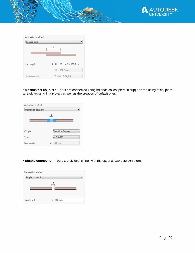
Four types of connection divided bars are available: • Lapped bars – bars are connected by lapping. The lap length value can be defined either directly or as a multiplier of a bar diameter.
Page 20
• Mechanical couplers – bars are connected using mechanical couplers. It supports the using of couplers already existing in a project as well as the creation of default ones.
• Simple connection – bars are divided in line, with the optional gap between them.
Page 21
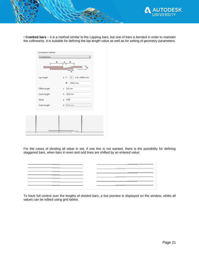
• Cranked bars – it is a method similar to the Lapping bars, but one of bars is bended in order to maintain the collinearity. It is suitable for defining the lap length value as well as for setting of geometry parameters.
For the cases of dividing all rebar in set, if one line is not wanted, there is the possibility for defining staggered bars, when bars in even and odd lines are shifted by an entered value:
To have full control over the lengths of divided bars, a live preview is displayed on the window, whilst all values can be edited using grid tables.
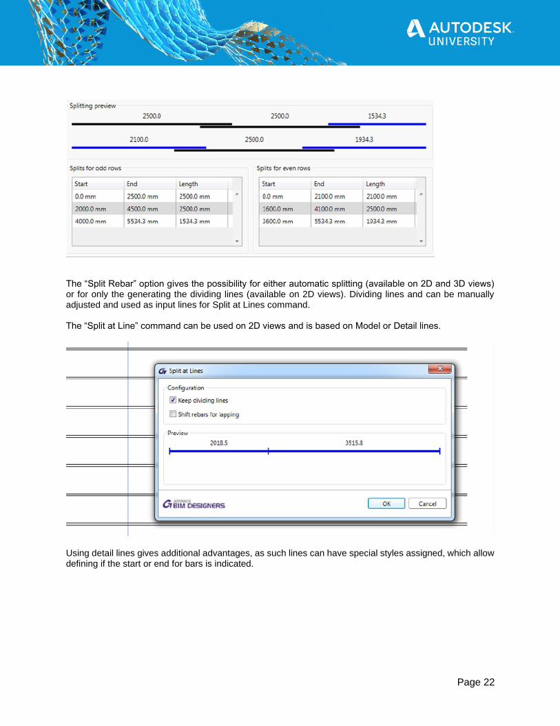
Page 22
The “Split Rebar” option gives the possibility for either automatic splitting (available on 2D and 3D views) or for only the generating the dividing lines (available on 2D views). Dividing lines and can be manually adjusted and used as input lines for Split at Lines command. The “Split at Line” command can be used on 2D views and is based on Model or Detail lines.
Using detail lines gives additional advantages, as such lines can have special styles assigned, which allow defining if the start or end for bars is indicated.

Page 23
By using different combinations, it is possible to get either simple splitting or lapping, or even to defy staggered lapping, when even and odd lines of bars are split using different lines.
Cranked bars
The new Cranked Bars command is used to quickly generate cranks at selected ends of longitudinal reinforcement bars. The command is available on the PowerPack Detailing ribbon:
This command is especially helpful in all situations where we want to avoid collisions of collinear bars.
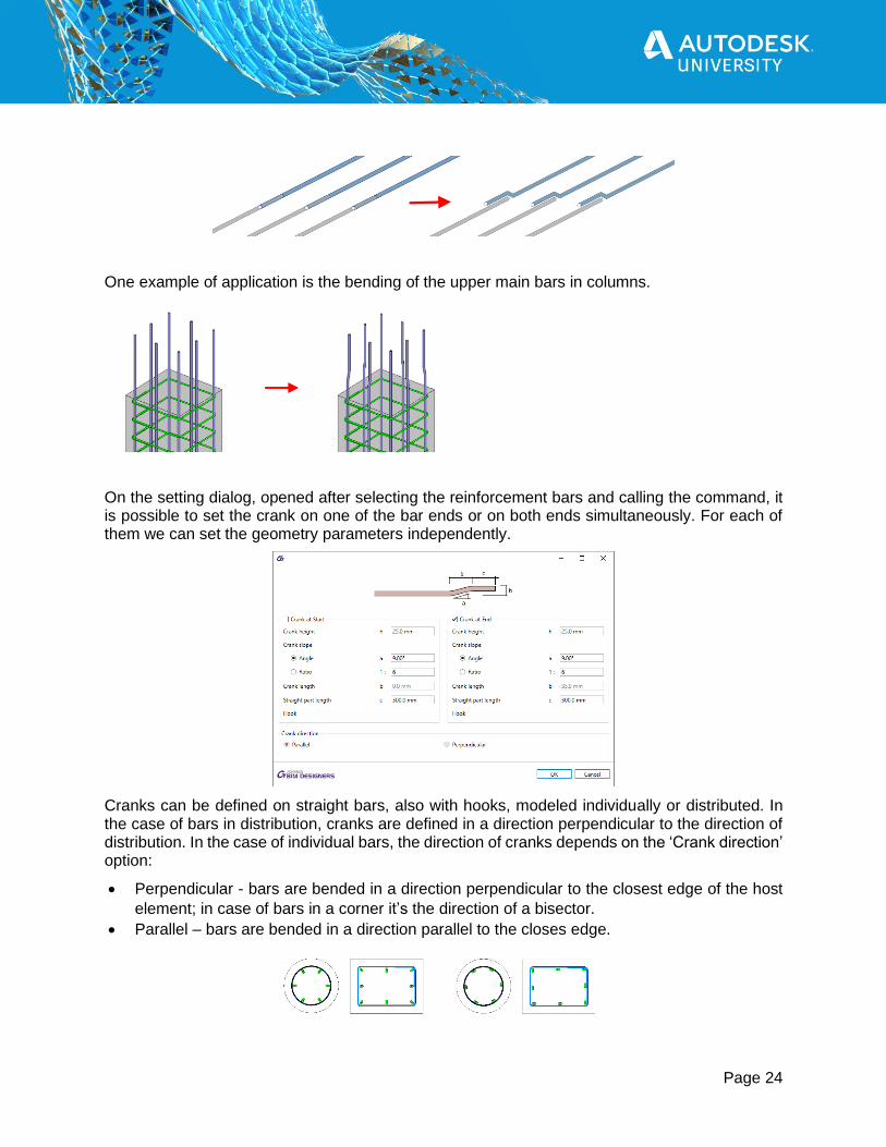
Page 24
One example of application is the bending of the upper main bars in columns.
On the setting dialog, opened after selecting the reinforcement bars and calling the command, it is possible to set the crank on one of the bar ends or on both ends simultaneously. For each of them we can set the geometry parameters independently.
Cranks can be defined on straight bars, also with hooks, modeled individually or distributed. In the case of bars in distribution, cranks are defined in a direction perpendicular to the direction of distribution. In the case of individual bars, the direction of cranks depends on the ‘Crank direction’ option:
• Perpendicular - bars are bended in a direction perpendicular to the closest edge of the host
element; in case of bars in a corner it’s the direction of a bisector.
• Parallel – bars are bended in a direction parallel to the closes edge.
Page 25
Detailing tools for rebar drawings
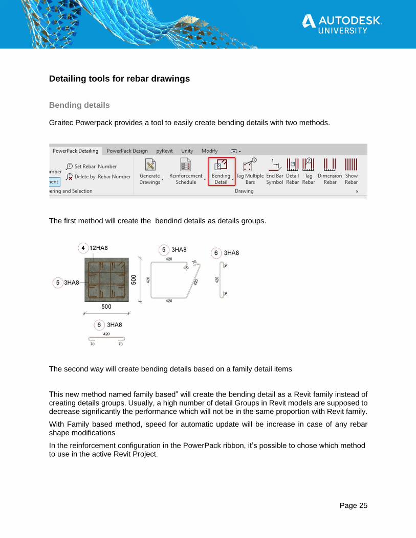
Bending details
Graitec Powerpack provides a tool to easily create bending details with two methods.
The first method will create the bendind details as details groups.
The second way will create bending details based on a family detail items
This new method named family based” will create the bending detail as a Revit family instead of creating details groups. Usually, a high number of detail Groups in Revit models are supposed to decrease significantly the performance which will not be in the same proportion with Revit family.
With Family based method, speed for automatic update will be increase in case of any rebar shape modifications
In the reinforcement configuration in the PowerPack ribbon, it’s possible to chose which method to use in the active Revit Project.

Page 26
Scaling factor can be applied to this bending detail and it will be created as a detail items family.
The tag can be placed as well and move independently from the schema itself

Page 27
Orthomode placement method by pressing Shift button and clicking to indicate the location point is still possible with this method.
In addition, by pressing Shift button and clicking on a structural element host, all bending details relative to all rebars belonging to this host will be placed in on click in the view. Then users could move them and place them wherever he wants for tuning the final drawings.
Change the Detail level of the view could change the representation of the bending detail as well. Medium and Fine level will create a bending schema representation with the all thickness of the bar represented.
Page 28
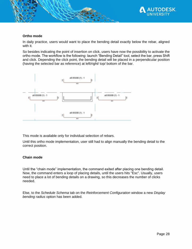
Ortho mode
In daily practice, users would want to place the bending detail exactly below the rebar, aligned with it.
So besides indicating the point of insertion on click, users have now the possibility to activate the ortho mode. The workflow is the following: launch “Bending Detail” tool, select the bar, press Shift and click. Depending the click point, the bending detail will be placed in a perpendicular position (having the selected bar as reference) at left/right/ top/ bottom of the bar.
This mode is available only for individual selection of rebars.
Until this ortho mode implementation, user still had to align manually the bending detail to the correct position.
Chain mode
Until the “chain mode” implementation, the command exited after placing one bending detail. Now, the command enters a loop of placing details, until the users hits "Esc". Usually, users need to place a lot of bending details on a drawing, so this decreases the number of clicks needed.
Else, to the Schedule Schema tab on the Reinforcement Configuration window a new Display bending radius option has been added.

Page 29
It allows for displaying on bar schemas the bend angle and the symbol and the value of bending diameter.
The tag for bending detail can now be selected from all the types of the current families of rebar tags loaded in the project.
End Bar Symbol
A new End Bar Symbol command, available on the Detailing ribbon, allows for a quick definition on 2D views a special symbol showing location of ends of straight bars. It is useful especially for cases, when rebars overlap on the view.

Page 30
The End Bar Symbol command supports two usage scenarios:
➢ called with existing rebar selection - symbols are defined automatically at both ends of
selected bars,
➢ called without any selection - a symbol it is defined at the end which is closer to the
indicated point on the bar.
The type of bar end symbol depends on the family used (Detail items category). The default family and type are selected in the Reinforcement Configuration window.
The family supplied with the program (Graitec EndBarSymbol) contains two types of symbols:
• tick (with or without bar mark annotation)
• tag (with or without bar mark annotation)
This family also allows for easy configuration of the size of the components as well as easy flipping

Page 31
Reinforcement layers
With the latest version, a new functionality has been introduced for assigning reinforcement to a layer (for example Top or Bottom) for easy and quick filtering of the reinforcement.
The layer might refer to a geometrical location of reinforcement but also to another purpose, such as its function.
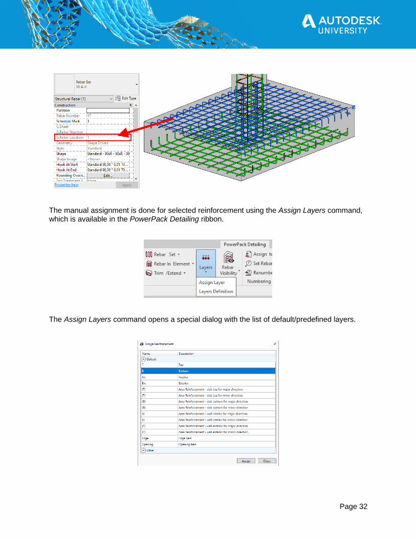
The information about the assigned layer is stored using shared parameters: G.Rebar Location for Structural Reinforcement and G.Fabric Location for Structural Fabric Reinforcement.
The assignment is done automatically and manually. The automatic method is applied during reinforcement generation using calculation modules or reinforcement generators in PowerPack. For example, the top bars in the foundation have an automatically assigned value T (a default name for a top reinforcement). Note - automatic assignment is made to the selected rebars, for example in the case of a foundation to the lower and upper bars in the pad.
Page 32
The manual assignment is done for selected reinforcement using the Assign Layers command, which is available in the PowerPack Detailing ribbon.
The Assign Layers command opens a special dialog with the list of default/predefined layers.

Page 33
The content of the list is based on the configuration from the Reinforcement Layers Definition window, opened by the Layers Definition command. The user can modify names for default layers, use the Active option to limit the list of layers that can be available during the assignment and add new positions/layers to the Other group.
The value of the layer parameter is mainly used in the new options of the tools for controlling the reinforcement visibility - see the part of the document related to improvements to the rebar visibility.
Rebar Visibilty This command help users to optimize display management for rebars on Revit views. There is not need to set parameters or edit the View visibility states in the properties panel, a simple dialog box will be proposed to users to set their own configuration.
Related Documents