An-Najah National University Faculty Of Engineering Department Of Mechanical Engineering Mechanical Systems Of Amar commercial Tower Graduation Project Submitted In Partial Fulfillment Of The Requirements For The Degree Of B.Sc. In Mechanical Engineering Supervisor: Dr. Salameh Abdel-Fattah The students: Khubaib Abu Omar (10740338) Jihad Al-Hindi (10717027) Samer Theeb (10717049) May May 2013

Welcome message from author
This document is posted to help you gain knowledge. Please leave a comment to let me know what you think about it! Share it to your friends and learn new things together.
Transcript

An-Najah National University
Faculty Of Engineering
Department Of Mechanical Engineering
Mechanical Systems Of Amar commercial Tower
Graduation Project Submitted In Partial Fulfillment Of The
Requirements For The Degree Of B.Sc. In Mechanical
Engineering
Supervisor:
Dr. Salameh Abdel-Fattah
The students:
Khubaib Abu Omar (10740338)
Jihad Al-Hindi (10717027)
Samer Theeb (10717049)
Ameed Masri (10718641)
May
May 2013

بسم الله الرحمن الرحيماإلهداء
إلى الرسول األكرم محمد صلى الله عليه وسلم
إلى روح الشهداء جميعا
إلى من ضحى وافني زهرة شبابه من اجلي ومن اجل إخوتي, إلىأبي الغالي اهدي هذه الثمرة اليانعة وهي هذا المشروع
كما اهديها إلى من سهرت الليالي وعانت قساوة األيام إلىأمي الحنونة
كما اهدي هذا المشروع إلى بالدي الغالية فلسطين
وال يفوتني أن أتقدم بالشكر واالمتنان إلى أساتذتي الكرام الذين وقفوا بجانبي طيلة الوقت حتى تمكنت من انجاز هذا
المشروع..... كما أنني أتقدم بالشكر والعرفان إلى جامعتنا الحبيبةالتي هيأت لنا كل السبل من اجل الوصول إلى الغاية والهدف
سائلين المولى عز وجل أن يوفقنا لخدمة ديننا وطننا الحبيب
بطاقة شكر
سالمة عبدعرفانا بالجميل نتقدم بالشكر الجزيل من الدكتور الذي لم يتفانى بتقديم جهوده من اجل انجاز هذا المشروع الفتاح
رامز الخالدي الذي حرص دائماالدكتوركما ونتقدم بالشكر إلى لوضعنا على الطريق الصحيح.

Ch.1. Introduction
1.1 Introduction ( Abstract )
The aim of this project is to design the (HVAC) system for building of ( Amar Tower )
which built in Ramallah city.
HVAC system provides environmental health, comfortable, clean and free of gems and
diseases. These consideration in the design will provide healthy and comfortable environment
within the hospital. Also insulation system and material construction will be taken into
account. Insulation system that be located in the walls and windows of the hospital to reduce
the amount of heat losses. While materials construction will provide the appropriate
temperature through the adjustment and suitable degree of moisture and maintain the
purification of the air inside the building is suitable and healthy.
The fire-fighting system will be designed to keep the building safe from fire accident.
Additionally, the water system and plumbing such as a network of hot and cold water. This
service can be achieved through the identification of the correct size for pipes.
1.2 Heating system
Heating system is designed to add the thermal energy to building to maintain selected air
temperature at an acceptable level. There are many types of heating systems that range from
built-in systems or hot air through air ducts.

1.2.1 Heating system components :
1. Boiler the heat source.
2. Cylinder to store the hot water.
3. Pump to push water around the system.
4. Timer to turn the hot water and heating system on automatically.
5. Room Thermostat to control the temperature of the house.
6. Cylinder Thermostat to control the hot water temperature.
7. Radiators to heat the room.
8. Chimney used to bring out the smoke of the burning heats the water in the boiler and
includes promoting ease and chimney fans, and liners are flexible, and leg guards,
plates of lead.
9. Burner a mechanical device that burns a gas or liquid fuel into a flame in a controlled
manner. [1]
1.2.2 The principle of operation heating system :
Boiler, radiators and interconnecting piping is the basic component of the water heating
system , the boiler heats the water and a pump circulate the heats water through the pipe and
radiators and back again to the boiler . there are many types and arrangement of boilers,
radiators and pipework , each systems has its advantage and disadvantages . A hot water

cylinder is used to store the domestic hot water. The system works at natural atmospheric
pressure as the feed/expansion tank is open to the air.
The feed/expansion tank is fitted high up above the rest of the system components, often in
the loft. The tank is fitted with a ball valve so that any water lost due to evaporation etc. is
automatically replaced, the tank also allows for the water in the system to expand when it is
heated, the ball valve need to be set very low so that the expanded water does not cause an
overflow. The tank also allows for any water vented from the system up the vent pipe to be
recovered, the vent pipe is connected from near the boiler and is bent over the tank .The
water is fed down to connect into the system between the boiler and pump adjacent to the
vent pipe as shown in figure (1.1). [2]

Fig.(1.1)
1.3 Cooling system
Cooling systems is designed for space cooling or process cooling. In specified applications, to maintain an acceptable level of cooling at high temperatures, there is many types of cooling systems such as air conditioning and fluid conditioning.
1.3.1 Cooling systems component :
1.3.1.1 Central Air Conditioners :

central air conditioners can be broken down into two different types – split system and packaged air conditioners:
1- Split system air conditioners – the more common of the two types of central air conditioners, split system air conditioners have the compressor / condenser
housed in a unit outdoors and the evaporator indoors. The primary benefit of split system air conditioners is that they keep the noisy part outside! Split system air conditioners connect into your existing ductwork, cooling your home evenly
and quietly.2- Packaged central air conditioners – less common in homes than split system
air conditioners, packaged air conditioners, as the name suggests, “package” the two components in a single unit, usually mounted on the roof or, occasionally, on a wall. If you’ve ever seen an air conditioning unit on the top of a building,
you’ve seen a packaged central air conditioner.
1.3.1.2 Portable Air Conditioners:
if you’ve ever lived in a small house or an apartment building, you’ve probably used a PTAC portable terminal air conditioner. Portable air conditioners are typically noisier and less efficient than central air conditioners and cool a much smaller area than central air conditioners. That said, if you have limited space or a limited budget, you won’t do much better than a portable air conditioner.
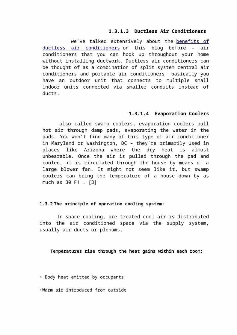
1.3.1.3 Ductless Air Conditioners
we’ve talked extensively about the benefits of ductless air conditioners on this blog before – air conditioners that you can hook up throughout your home without installing ductwork. Ductless air conditioners can be thought of as a combination of split system central air conditioners and portable air conditioners basically you have an outdoor unit that connects to multiple small indoor units connected via smaller conduits instead of ducts.
1.3.1.4 Evaporation Coolers
also called swamp coolers, evaporation coolers pull hot air through damp pads, evaporating the water in the pads. You won’t find many of this type of air conditioner in Maryland or Washington, DC – they’re primarily used in places like Arizona where the dry heat is almost unbearable. Once the air is pulled through the pad and cooled, it is circulated through the house by means of a large blower fan. It might not seem like it, but swamp coolers can bring the temperature of a house down by as much as 30 F! . [3]
1.3.2 The principle of operation cooling system:
In space cooling, pre-treated cool air is distributed into the air conditioned space via the supply system, usually air ducts or plenums.

Temperatures rise through the heat gains within each room:
• Body heat emitted by occupants
•Warm air introduced from outside
•Heat generated by lights and other electrical and mechanical equipment.
• Solar heat gain through windows.
• Heat gain through the building fabric and abutting non-air conditioned space.
Heat is transferred from the room to the outside atmosphere in a four-stage heat
transfer process :
• Stage 1—Heat is removed from the conditioned space by extracting the room air.
• Stage 2—Heat is exchanged from the extracted warm room air by passing the air over a
coolant circulating in the cooling coil inside an air conditioning system.
• Stage 3—Heat is extracted from the coolant by refrigerant compression and evaporation in
the chiller and transferred to the condenser of the chiller.
• Stage 4—Heat is normally rejected to the atmosphere from the condenser via a cooling
tower (water cooled) or via fan-forced ambient air passing through the condenser (air cooled).
[4]
1.4 Ventilation
In HVAC system , the process of ventilation is changing the air in the space , control
temperature , humidity , dust and airborne bacteria. This process includes of air as well as
circulation from the outside and inside building. All occupied buildings require a supply of
outdoor air. Depending on Outdoor conditions, the air may need to be heated or cooled
before it is distributed into the occupied space. As the outside air drag into the building ,
indoor air allowed to escape , this process will remove the air contaminants.
The ventilation system can be designed only to supply enough air to the room to meet the
requirements for acceptability of the air quality.
1.4.1 Mechanical or forced ventilation:
mechanical ventilation is a process which we use an external load to ventilate the space ,
such as air conditioning system or just about any type of fan.
1.4.2 Natural ventilation:
natural ventilation ,is a process which you can ventilate any space without using an external
force by knowing the differences in pressure inside and outside the space.
natural ventilation can be very effective when it comes cooling an indoor environment but
that's will allow the contaminants which comes from outside to move inside the space
unimpeded .
On hot or humid days, natural ventilation can’t reduce the indoor temperature enough to
make it comfortable indoors. While a light breeze is enough to take the edge off on a
moderate spring or summer day, more is needed when the weather is extreme.
1.5 Air conditioning:
Air conditioning is the removal of heat from indoor air for thermal comfort. In summer, high
relative humidity, elevated air temperature and bright sunshine can sometimes combine to
produce an uncomfortable indoor environment. An air conditioning system can provide
comfort for occupants by decreasing the air temperature and humidity level at home. [5]

1.5.1 types of air conditioners :
The HVAC designer will recommend different types of air conditioning systems
for different applications. These have been described in this article. The most
commonly used air conditioning units are window and split air conditioners.
1- Window Air Conditioners:
A common type of air conditioner is the window type. It is basically a single box that is fitted in a window sill or in a makeshift slot in the wall of the room. This is usually found in most residential homes. Window type air conditioners have all of its parts (condenser, compressor, expansion valve or coil, cooling coil and evaporator) enclosed inside a single box. All kinds of residential houses will go well with this type of air con.
2- Split System Air Conditioners:
Second, the split system air conditioner is unlike the window-type. Instead of all parts in a single box, this type has an indoor unit (which has the cooling fan and the evaporator) and an outdoor unit (compressor, condenser and expansion valve). One won’t have cut a hole in a wall in install a split unit. And because of its design, these types of air conditioners is more preferred for its simple looks that can blend in with any room décor. It can also be use to cool one or two rooms. The split system air conditioner is also okay with all kinds of residential homes.
3- Commercial Air Conditioners:
Commercial and industrial buildings, however, need larger air conditioners to cool the larger spaces. The types of air conditioners for this setting are the packaged air conditioners and the central air conditioning system.
The packaged air conditioners have two optional settings. In the first one, all the parts of an air con are enclosed in a single outdoor unit, and then the cooled air is flown through the ducts

located in the rooms. In the second arrangement, the condenser and compressor are housed in a single unit, and then the compressed gas are passed through multiple units (with the expansion valve and cooling coil) located in the rooms. This is basically like the split-type air conditioners, but designed to cool larger, multiple spaces.
1.5.2 Air Conditioner Components :
1. Chiller the cooling source.
2. Pipes to transport the chilled water.
3. Pump to push water around the system.
4. Timer to turn the cold water and cooling system on automatically.
5. Room Thermostat to control the temperature of the house.
6. Duct to transport the chilled air or to exhaust air drag or for the return air.
7. F.C.U The cooled air passes through the cold water and distribution space.
8. A.H.U The cooled air passes through the cold water coming from water chillers and
distribution space through the duct. [6]
1.6 Comfort zone
Comfort within buildings is primarily by four factors: air temperature, humidity, mean
radiant temperature and airflow .
Many statistical studies have been performed on large number of subjects of all ages, sexes
and nationalities to arrive at quantitative description of human comfort. This is necessary to
provide the goals and design parameters for human comfort in buildings.
1.6.1 ASHERE COFORT CHART

Thermal radiation and air speed are mainly outdoor effects which are difficult to
control and measure. Therefore, literature on thermal comfort focuses on humidity
and temperature as shown in Figure (1.2).
There is no rigid rule that indicates the best atmospheric condition for comfort for all
people. Because it is affected by several factors such as health, age, activity, clothing,
sex, Food, etc. comfort conditions are obtained as a result of tests in which people are
subjected to air as various combinations of temperature and relative humidity. The
result of such tests indicate that a person will feel just about as cool at 24Co and 60%
relative humidity as at 26Co and 30% relative humidity. Studies continued by ASHREA
with relative humidity between 30% and 70% indicates that 98% of people feel
comfortable when the temperature and relative humidity combinations fall in a
comfort zone as shown in Figure (1.2).
The comfort zone covers a wide range of applications such as houses, offices, schools,
hospitals, theaters, restaurants, shops, etc. the most recommended design conditions
for comfort are 24.5Co dry bulb temperature and 40% relative humidity with air
velocity less than 0.23 m/s.
The comfort zone in figure (1.2) is considered a standard comfort zones for summer
and winter applications. It sets the limit of both the operation temperature and
humidity contents of air for these zones. From the figure as the humidity increases the
dry bulb temperature must decrease to keep comfortable environment. The ASHREA
comfort chart defines the reference base of the effective temperature scale as that of
the 50% RH curve. [7]

Fig(1.2)

1.7 Fire alarm system:
Fire protection is the study and practice of mitigating the unwanted effects of fires.
It involves the study of the behavior, compartmentalization, suppression and
investigation of fire and its related emergencies, as well as the research and
development, production, testing and application of mitigating systems.
In structures, be they land-based, offshore or even ships, the owners and operators
are responsible to maintain their facilities in accordance with a design-basis that is
rooted in laws, including the local building code and fire code, which are enforced by
the Authority Having Jurisdiction. Buildings must be constructed in accordance with
the version of the building code that is in effect when an application for a building
permit is made.
Building inspectors check on compliance of a building under construction with the
building code. Once construction is complete, a building must be maintained in
accordance with the current fire code, which is enforced by the fire prevention officers
of a local fire department. In the event of fire emergencies, Firefighters, fire
investigators, and other fire prevention personnel called to mitigate, investigate and
learn from the damage of a fire. Lessons learned from fires are applied to the
authoring of both building codes and fire codes.
1.8 Plumping:
Plumping is the art of installing in building the pipes, fixtures and other apparatus for bringing in the water supply and removing liquid and water-carried wastes. Plumping fixtures are receptacles intended to receive and discharge water, liquid or water-carried wastes into a drainage system with which they are connected. Plumping system of a building includes the water supply distributing pipes, the fixtures and fixtures traps, the soil, waste and vent pipes, the house drain and house sewer, the storm water drainage, and all the devices, appurtenances and connections of the above within or adjacent to the building.

Ch.2. Building's Descriptions
2.1 Introduction: This chapter describes the building details, which include the usage of the building,
wall and ceiling construction, and the parameter that used in calculation of heating
and cooling load and the inside and outside design parameter.
The Tower contains from 12 floors, and that building contains offices, commercials
stores, theater, parkings, kitchens, and bathrooms.
The Tower Building consists of nine floors, three basements. There are different
applications inside the Building as the table (2.0) shows.
Table (2.0): Building floors applications
Floor No. Use
Ground floor 8 gallery shop, security office,pantry,2 security
room, 2 back office control room, lobby
First floor 8 gallery shop
,pantry
,lobby
Second floor 5 offices, Reception foyer, Kitchen, Lower
auditorium, Lobby
Third floor 6 offices, Auditorium, Lobby
Fourth floor Aerobics, Workout space, lockers room, Prayer
hall, Ketchen, coffee shop hall, Lobby

Fifth floor Open area, sub server room, Lobby
Sixth floor Offices and lobby
Seventh floor Offices and lobby
Eighth floor Offices and meeting rooms and lobby
2.2 Location Country: Palestine / west bank.
City: Ramallah/ Ersal st. .
Elevation: 874 m above sea level.
Latitude: 32N.
Longitude:35 E.
Building face sits at west orientation.
The wind speed in Ramallah above 5 m/s.
2.3 Climate zone: Palestine is generally divided into six climatology regions. And thus Ramallah sit in forth
region according to the Palestinian code. The maximum and minimum temperatures for each
month are tabulated in table (2.1) [1]. And the outside and inside design conditions are shown in
table (2.2) [2].
Table (2.1): maximum and minimum temperature for each month

Table (2.2): outside and inside design conditions

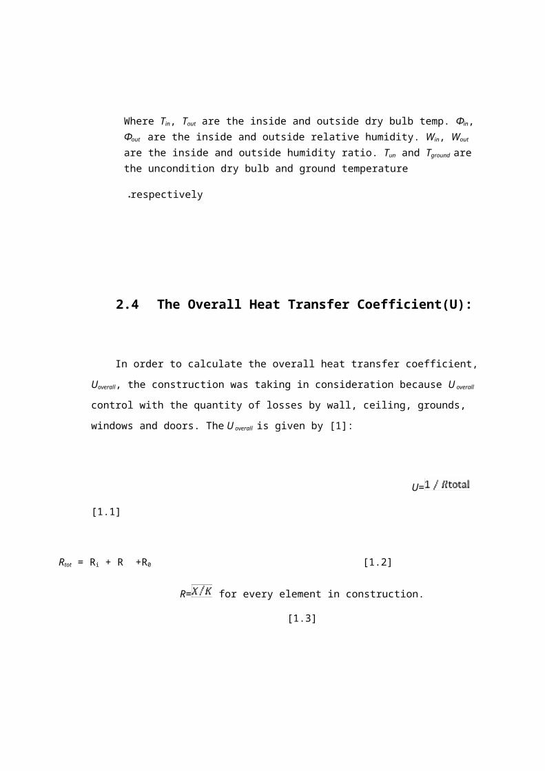
Where Tin, Tout are the inside and outside dry bulb temp. Фin, Фout are the inside and outside relative humidity. Win, Wout are the inside and outside humidity ratio. Tun and
Tground are the uncondition dry bulb and ground temperature respectively .
2.4 The Overall Heat Transfer Coefficient(U):
In order to calculate the overall heat transfer coefficient, Uoverall, the construction was taking in
consideration because U overall control with the quantity of losses by wall, ceiling, grounds,
windows and doors. The U overall is given by [1]:
U= [1.1]
Rtot = Ri + R +R0 [1.2]
R= for every element in construction. [1.3]
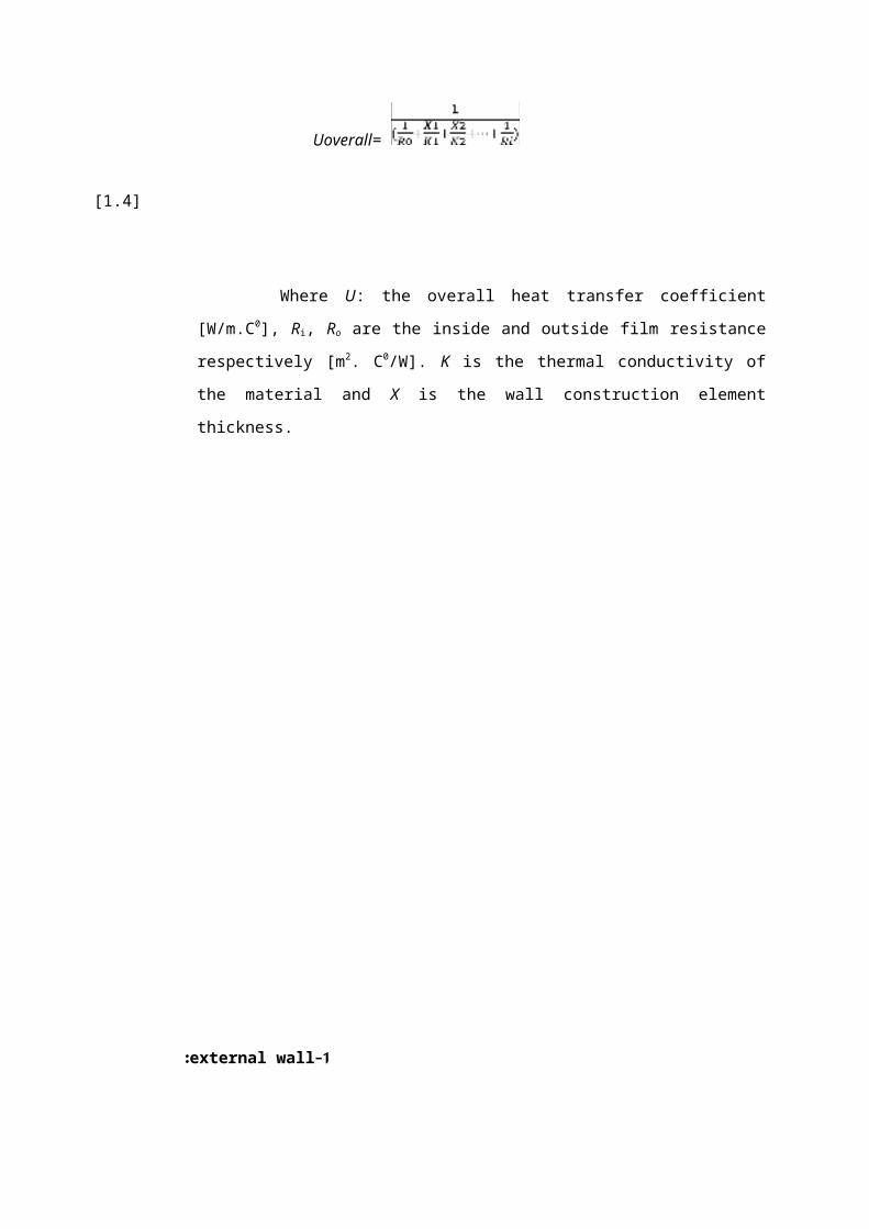
Uoverall= [1.4]
Where U: the overall heat transfer coefficient [W/m.C0], Ri, Ro are the inside and
outside film resistance respectively [m2. C0/W]. K is the thermal conductivity of the
material and X is the wall construction element thickness.
1-external wall:
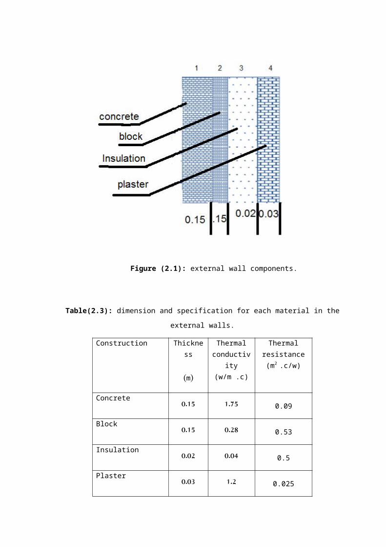
Figure (2.1): external wall components.

Table(2.3): dimension and specification for each material in the external walls.
The external walls contents of four parts, These parts are block, concert, plaster and
insulation. The arrangements of these parts and their thickness , thermal conductivity and
thermal resistance are shown figure in figure(2.1)and tabulated in table (2.3).
Ro =0 .03
m².˚C/W for Walls, from A-20
Ri = 0.12 m².˚C/W for Walls, from A-20
Ri = 0.15 m².˚C/W for Ceiling, from A-20
Thermal resistance (m2
.c/w)
Thermal conductivity
(w/m .c)
Thickness
(m)
Construction
0.091.750.15Concrete
0.530.280.15Block
0.50.040.02Insulation
0.0251.20.03Plaster

0.02 m2.˚C/W for ceiling, from A-20 = Ro
R=
Sample of calculation:
*for external wall:
R=(0.15/1.75)+(0.15/0.28)+(0.02/.04)+(0.03/1.2)=1.146 m2.c/w.
Rtotal= Ri+ R+ Ro
Rtotal =0.12+1.146+0.03=1.296 m2.c/w.
U=1/Rtotal =1/.18=0.755.
2-Internal wall:
The internal walls contents of two parts which are plaster and block the dimension for
each part as shown figure and the specification on table

Fig (2.2):Internal wall components.
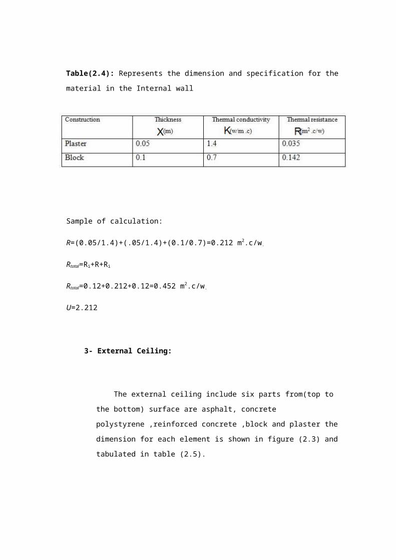
Table(2.4): Represents the dimension and specification for the material in the Internal wall
Sample of calculation:
R=(0.05/1.4)+(.05/1.4)+(0.1/0.7)=0.212 m2.c/w.
Rtotal=Ri+R+Ri
Rtotal=0.12+0.212+0.12=0.452 m2.c/w.
U=2.212
3- External Ceiling:
The external ceiling include six parts from(top to the bottom) surface are asphalt,
concrete polystyrene ,reinforced concrete ,block and plaster the dimension for each
element is shown in figure (2.3) and tabulated in table (2.5).
Table(2.5): Represents the dimension and specification for the material in the External
Ceiling .
Sample of calculation:
R=(0.02/0.7)+(.03/0.04)+(0.05/2.1)+(0.03/2.1)+(0.15+1.1)+(0.02+1.4)=0.9602 m2.c/w.
Rtotal=Ri+R+R0
Rtotal=0.15+0.9602+0.02=1.1302 m2.c/w.
U=0.885
4- Internal ceil:
The internal ceiling include six parts from(top to the bottom) surface are tiles, concrete
polystyrene ,reinforced concrete ,block and plaster the dimension for each element is shown
in figure (2.4) and tabulated in table (2.6).
Table(2.6): Represents the dimension and specification for the material in the Internal
Ceiling .
2.5 Summary:
The overall heat transfer coefficient Uoverall was calculated for the building external and
internal walls and ceiling, additionally from appendix A, the Uoverall for windows and doors
are taken. These values are tabulated in (2.7):
Table (2.7): Uoverall for the building.
The overall heat transfer coefficientBuilding contain
0.755External wall
2.212Internal wall
0.885External ceiling
3.5Door (glass)
3.6Door(wood)

Ch.3. Heating
3.1 Introduction:
The heat loss is divided into two groups:
The heat transmission losses through the confining walls, floor, ceiling, glass, or other
surfaces, and The infiltration losses through cracks and openings, or heat required to
warm outdoor air used for ventilation.
As a basis for design, the most unfavorable but economical combination of temperature
and wind speed is chosen. The wind speed has great effect on high infiltration loss and
on outside surface resistance in conduction heat transfer.
Normally, the heating load is estimated for winter design temperature usually occurring
at night; therefore, internal heat gain is neglected except for theatres, assembly halls,
industrial plant and commercial buildings. Internal heat gain is the sensible and latent
heat emitted within an internal space by the occupants, lighting, electric motors,
electronic equipment, etc.
3.2 Heat Losses in Human Body:
People are loss heat in four modes:
Evaporation.
Radiation.
Convection.
Conduction.
3.2.1 Evaporation:

This accounts for the removal of about 25% of the body heat. There are two mechanics
of evaporation and a balancing reaction to respond to varying environment; Respiration,
Insensible skin moisture.
3.2.2 Radiation:
` As the body or the clothing over it is at a higher temperature than the
environment, heat loss from the body to the environment takes place continuously. The
heat loss from the body by this modes accounts for about 45% of total heat loss of the
body.
3.2.3 Convection:
Heat is removal from the body by the air movement around the body; the air movement
is due to heating the air in contact with the body, or by the wind in the environment.
The heat loss by convection accounts to about 30% of the total heat loss by the body.
3.2.4 Conduction:
This heat loss results from direct contact of the body with object in its surrounding.
However, as far as normal human beings are considered the heat loss by this mode is
negligible.
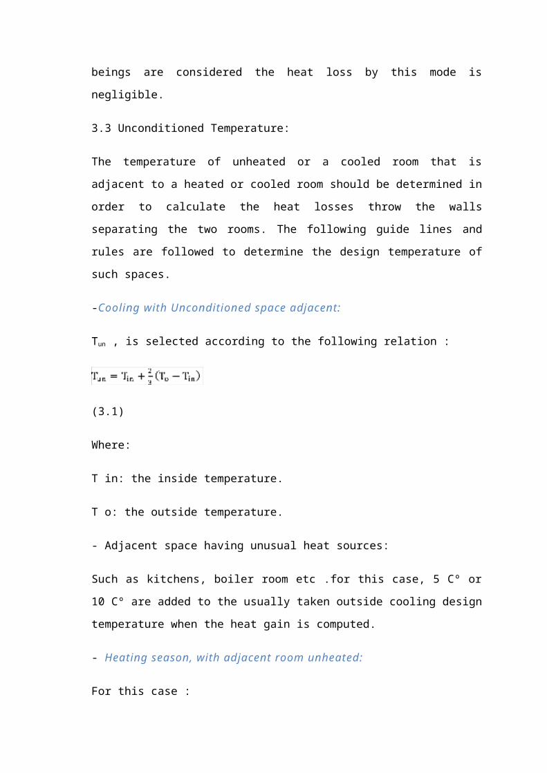
3.3 Unconditioned Temperature:
The temperature of unheated or a cooled room that is adjacent to a heated or cooled
room should be determined in order to calculate the heat losses throw the walls
separating the two rooms. The following guide lines and rules are followed to determine
the design temperature of such spaces.
-Cooling with Unconditioned space adjacent:
Tun , is selected according to the following relation :
(3.1)
Where:
T in: the inside temperature.
T o: the outside temperature.
- Adjacent space having unusual heat sources:
Such as kitchens, boiler room etc .for this case, 5 Cº or 10 Cº are added to the usually
taken outside cooling design temperature when the heat gain is computed.
- Heating season, with adjacent room unheated:
For this case :
(3.2)
(3.3)
-Ground floors directly on the ground:
(3.4)
3.4 General Procedures for Calculating Total Heat Load:
Select inside design condition (Temperature, relative humidity).
Select outside design condition (Temperature, relative humidity).
Select unconditioned temperature.
Find over all heat transfer coefficient Uo for wall, ceiling, floor, door, windows, below
grade.
Find area of wall, ceiling, floor, door, windows, below grade.
Find Qs conduction.
Find V inf, V vent.

Find Qs, QL vent, inf.
Find Q domestic hot water.
Find Q total and Q boiler.
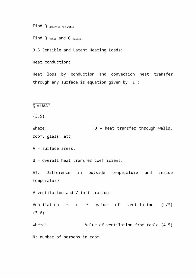
3.5 Sensible and Latent Heating Loads:
Heat conduction:
Heat loss by conduction and convection heat transfer through any surface is equation
given by [1]:
(3.5)
Where: Q = heat transfer through walls, roof, glass, etc.
A = surface areas.
U = overall heat transfer coefficient.
ΔT: Difference in outside temperature and inside temperature.
V ventilation and V infiltration:
Ventilation = n * value of ventilation (L/S) (3.6)
Where: Value of ventilation from table (4-5)
N: number of persons in room.
(3.7)
A: Area.
ACH: Air change per hour.
Qs, QL Ventilation, Infiltration (Heat loss by infiltration and ventilation):

We calculate Vvent,inf and select the maximum value of them , Then substitute
maximum value in those equation is given by [1]:
(3.8)
(3.9)
Q domestic hot water:
(3.10)
Where:
T: (Th –Tc) =50 Co
Cp: specific heat = 4180 J/kg. K.
Q total and Q boiler:
A. For hot water system:
(3.11)
B. For air system:
(3.12)
(3.13)
3.6 Sample of Calculations:
Sample calculations for (room 1) at second floor:

Heating design conditions (in winter)
Out design conditions :
Outside temperature
Relative humidity: 70 %
Inside design conditions:
Inside temperature
Relative humidity: 32%
The required overall heat transfer coefficients in our calculation:
,
Conduction heat loss (Gallery shop -4- in ground floor)

Q out side wall = ( 0.755 ) ( 65.826 ) ( 22 - 4.7 ) = 979.39 W
(3.14)
note :there is no losses from (inner wall, ceiling)
QFloor = ( 1.0525 ) ( 79.614 ) ( 22 - 4.7 ) = 1449.6316 W
QDoor = ( 3.5 ) ( 7.2 ) ( 22 - 4.7 ) = 435.96 W
QWindow = ( 3.5 ) ( 34.344 ) ( 22 - 4.7 ) = 2079.5292 W
Quncondition = ( 2.212 ) ( 72.979 ) ( 22 - 4.7 ) = 3062.78778 W
Note: (wind speed >5 m/s)
………………………………………………………… (3.15)
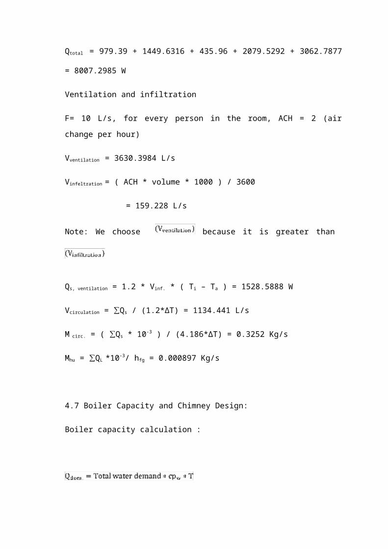
Qtotal = 979.39 + 1449.6316 + 435.96 + 2079.5292 + 3062.7877 = 8007.2985 W

Ventilation and infiltration
F= 10 L/s, for every person in the room, ACH = 2 (air change per hour)
Vventilation = 3630.3984 L/s
Vinfeltration = ( ACH * volume * 1000 ) / 3600
= 159.228 L/s
Note: We choose because it is greater than
Qs, ventilation = 1.2 * Vinf. * ( Ti – Ta ) = 1528.5888 W
Vcirculation = ∑Qs / (1.2*∆T) = 1134.441 L/s
M circ. = ( ∑Qs * 10-3 ) / (4.186*∆T) = 0.3252 Kg/s
Mhu = ∑QL *10-3/ hfg = 0.000897 Kg/s
4.7 Boiler Capacity and Chimney Design:
Boiler capacity calculation :
= 4.186*5*50 = 1046.5 KW
(3.16)
= 873337.1218 KW
(3.17)
= 960.6708 KW
Chimney design:
C.V: calorific value of the fuel used C.V (diesel) = 39000 KJ/Kg
Efficiency for diesel is 80% Atmospheric pressure (Pa) = 1.013 bar
Ambient temperature (Ta) =25 C0= 298 K Gas temperature (Tg) =250 C0=523 K
Gravity acceleration = 9.81 m/s2 Building high (H) =14 m
Ideal gas constant (Ra) = 287 J/Kg.K Density of diesel () = 1.1 Kg/m3
Velocity (v) = 5-12 m/s
D: diameter of chimney
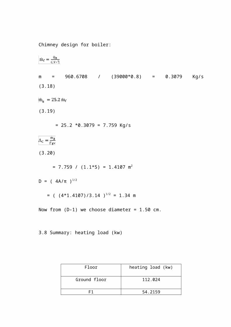
Chimney design for boiler:
m = 960.6708 / (39000*0.8) = 0.3079 Kg/s
(3.18)
(3.19)
= 25.2 *0.3079 = 7.759 Kg/s
(3.20)
= 7.759 / (1.1*5) = 1.4107 m2
D = ( 4A/π )1/2
= ( (4*1.4107)/3.14 )1/2 = 1.34 m
Now from (D-1) we choose diameter = 1.50 cm.
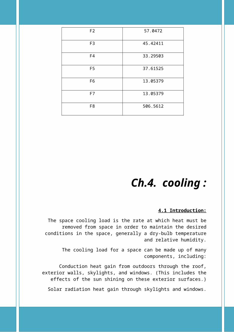
3.8 Summary: heating load (kw)

Floor heating load (kw)
Ground floor 112.024
F1 54.2159
F2 57.0472
F3 45.42411
F4 33.29503
F5 37.61525
F6 13.05379
F7 13.05379
F8 506.5612
Ch.4. cooling :
4.1 Introduction:
The space cooling load is the rate at which heat must be removed from space in order to maintain the desired conditions in the space, generally a dry-bulb temperature and
relative humidity.
The cooling load for a space can be made up of many components, including:
Conduction heat gain from outdoors through the roof, exterior walls, skylights, and windows. (This includes the effects of the sun shining on these exterior surfaces.)
Solar radiation heat gain through skylights and windows.
Conduction heat gain from adjoining spaces through the ceiling, interior partition walls, and floor.
Internal heat gains due to people, lights, appliances, and equipment in the space.
Heat gain due to hot, humid air infiltrating into the space from outdoors through doors, windows, and small cracks in the building envelope. In addition, the cooling coil in the
building HVAC system has to handle other components of the total building cooling load, including:
Heat gain due to outdoor air deliberately brought into the building for ventilation purposes.
Heat generated by the fans in the system and possibly other heat gains in the system.
4.2 Peak Hour One of the more difficult aspects of estimating the maximum cooling load for a space is
determining the time at which this maximum load will occur. This is because the individual components that make up the space cooling load often peak at different times
of the day, or even different months of the year.
For example, the heat gain through the roof will be highest in the late afternoon, when it is warm outside and the sun has been shining on it all day. Conversely, the heat gain due
to the sun shining through an east-facing window will be highest in the early morning when the sun is rising in the east and shining directly into the window. So, determining
the time that the maximum total space cooling load occurs will be essentially in Calculation.
4.3 Cooling Load Component

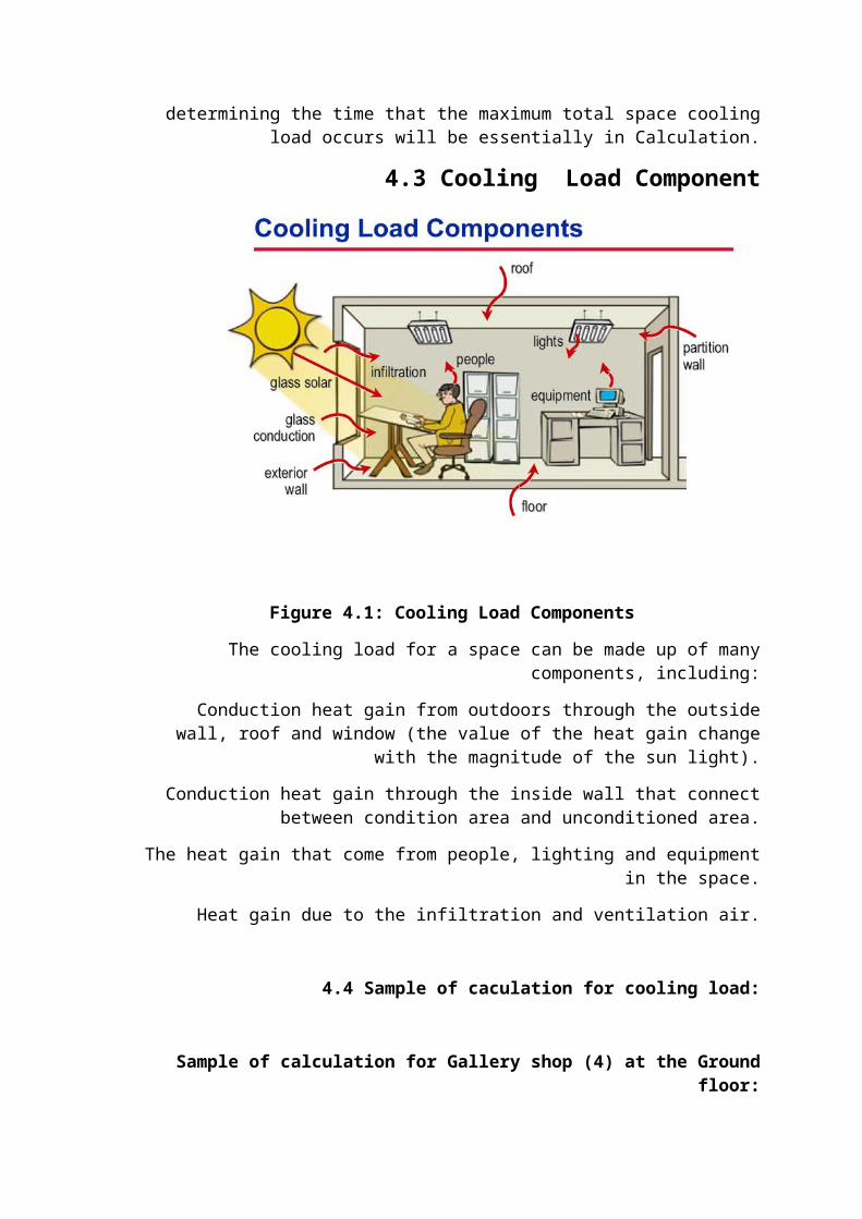
Figure 4.1: Cooling Load Components
The cooling load for a space can be made up of many components, including:
Conduction heat gain from outdoors through the outside wall, roof and window (the value of the heat gain change with the magnitude of the sun light).
Conduction heat gain through the inside wall that connect between condition area and unconditioned area.
The heat gain that come from people, lighting and equipment in the space.
Heat gain due to the infiltration and ventilation air.
4.4 Sample of caculation for cooling load:
Sample of calculation for Gallery shop (4) at the Ground floor:
Cooling design conditions given by :
*outside design condition:
Outside temperature : To =30oC
Relative humidity: 62%
W0 =16
*inside design condition:
Inside temperature: Ti =21oC

Relative humidity:50% Wi =7.5 Tg =40 oC
Some important parameters were taken in our consideration for cooling calculation:
Wall color assumed to be light color because it construct of stone so the color factor K=0.65
Ceiling color assumed to be light colored roof so that the color factor K=0.5
All equipment that used in this building are unhooded and it will run about 14 hours daily.
The heating load that comes from the equipment in this room equal 160 W.
Wall group is A, and ceiling group is 12.
We selected peak hour at 12 PM at June.
The height of this room 3m and 60cm for false ceiling.
*The table below shows the factor that will used to calculate the cooling load:
Table )4.1(: shows the factors for ceiling and roof.
CLTD= 17 from table (9-1)
LM=1.1 from table (9-2)
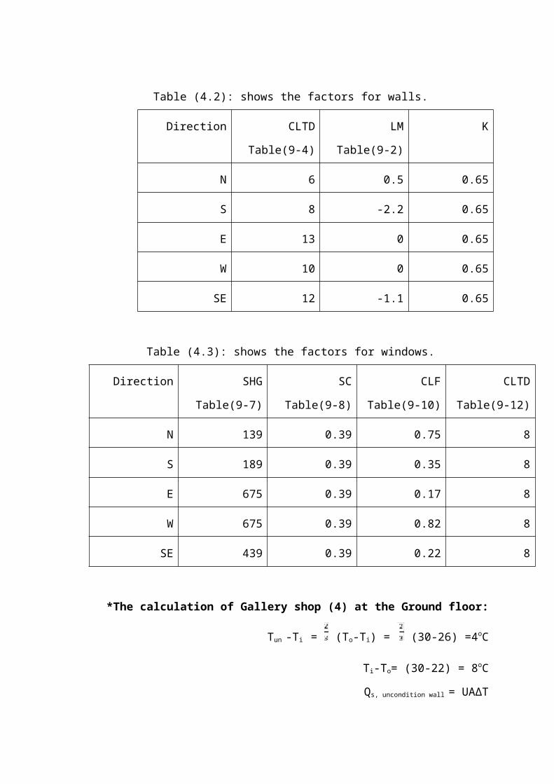
Table )4.2(: shows the factors for walls.
Direction CLTD
Table(9-4)
LM
Table(9-2)
K
N 6 0.5 0.65
S 8 -2.2 0.65
E 13 0 0.65
W 10 0 0.65
SE 12 -1.1 0.65
Table )4.3(: shows the factors for windows.

Direction SHG
Table(9-7)
SC
Table(9-8)
CLF
Table(9-10)
CLTD
Table(9-12)
N 139 0.39 0.75 8
S 189 0.39 0.35 8
E 675 0.39 0.17 8
W 675 0.39 0.82 8
SE 439 0.39 0.22 8
*The calculation of Gallery shop (4) at the Ground floor:
Tun -Ti = (To-Ti) = (30-26) =4oC
Ti-To= (30-22) = 8oC
Qs, uncondition wall = UA∆T
Qs,uncondition wall= ( 2.212 ) * ( 72.979 ) * ( 8 ) = 1291.436W
Qs,d,in(glass) = UA∆T = (3.5)*(7.2)*(4) =100.8W
Qs,floor= UA∆T
= (1.0525) * (79.614) * (4) = 335.17494W
*For ceiling:
=( 17 + 1.1 ) * 0.5 +( 25.5 - 22 ) + ( 30 - 29.4 ) = 14.15oC
Qs,ceiling = UA
= 0W *because the ceiling located between two condition floor.
* South east direction:
Area of gallery shop (4) = 79.614 m2
Area of outside wall = 245.40 m2
Area of inside wall = 0 m2
Area of inside door (glass) = 7.2 m2
Area of window = 34.344 m2

*For outside wall:
= ( 9 – 1.1 ) * 0.65 + ( 25.5 - 22) + ( 30 - 29.4 ) = 4.335
Qwall = UA
Qwall = 245.4 * 0.755 * 4.335 = 803.17W
Where:
LM = latitude correction factor.
K= Color adjustment factor.
K=1 for dark colored walls.
K= 0.83 for permanently medium color wall.
K=0 .65 for permanently light color wall(we use this type of wall).
A = area of external wall or roof.
U = overall heat transfer coefficient of the external wall or roof.
CLTD values are found from tables, as shown in Tables above, which are designed for fixed conditions of outdoor/indoor temperatures, latitudes, etc. Corrections and
adjustments are made if the conditions are different.
*For transmitted through glass:
Q = U ( SHG ) ( SC ) ( CLF )
Q = 3.5 * 439 * 0.9 * 0.49 = 6648.964W
*For convection through glass:
= (CLTD) + (25.5-Ti)+(To-29.4)
= ( 5 - 1.1 ) + ( 25.5 – 22 ) + ( 30 - 29.4 ) = 1.735
Q = UA
Q = 3.5 * 34.344 * 1.735 = 208.5539W
Heat loss from people, lighting and equipment:
*people:
CLF= 0.13 qs=71.5 W ql= 71.5 W
Qs = qs * n * CLF
Qs = 7 * 0.13 * 71.5 = 59.2W
Ql = ql * n * CLF
Ql = 7 * 0.13 * 71.5 = 59.2W
*lighting:
Qs = A * factor (15) * CLF
= 79.614 * 15 * 0.78 = 931.483W
*Equipment:
The room contain equipments:
Qs = 124.3W
Total of sensible and latent:
Qs,tot = Qs,in,wall+Qs,out,wall+Qs,lighting+Qs,door+Qs,ceiling+Qs,window+Qs,people
+Qs,equipment
Qs,tot = 10890.631 W
Ql,tot = Ql,people + Ql,lighting + Ql,equipment
= 2197.861 W
*Ventilation and Infiltration for cooling:
V = 15 L/s, for every person in the room, ACH = 2 (air change per hour)
Vventilation = # of person * V = 7 * 15 = 105 L/s
Vinfiltration= = = 159.228 L/s
*We choose Vventilation because it grater than Vinfiltration.
Qs,vent,inf = 1.2 * Vvent * ( To - Ti ) = 1.2 * 159.228 * 8 = 1528.5888 W
QL,vent,inf = 3 * Vvent * ( Wo - Wi ) = 3 * 159.228 * 4.4 = 2101.8069 W
Vcirculation =
Vcirculation = = 1134.441 L/s → 1134.441 * 2.2 = 2214.423 CFM
mcirculation = = 0.3252 Kg/s
4.5 Result:

The result of cooling load calculation for all room are shown in appendix
4.6 Summary:
table )4.4( cooling load for each floor
Floor Cooling load (KW)
Ground floor190857.055
F1145879.969
F2162423.027
F3146750.280
F4114806.218
F586402.632
F6121420.24
F7121420.24
F8124277.81
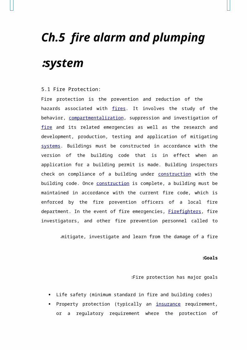
Ch.5 fire alarm and plumping system:
5.1 Fire Protection:
Fire protection is the prevention and reduction of the hazards associated with fires. It
involves the study of the behavior, compartmentalization, suppression and investigation of fire
and its related emergencies as well as the research and development, production, testing and
application of mitigating systems. Buildings must be constructed in accordance with the
version of the building code that is in effect when an application for a building permit is made.
Building inspectors check on compliance of a building under construction with the building
code. Once construction is complete, a building must be maintained in accordance with the
current fire code, which is enforced by the fire prevention officers of a local fire department. In
the event of fire emergencies, Firefighters, fire investigators, and other fire prevention
personnel called to mitigate, investigate and learn from the damage of a fire.
Goals:
Fire protection has major goals:
Life safety (minimum standard in fire and building codes)
Property protection (typically an insurance requirement, or a regulatory requirement
where the protection of building components is necessary to enable life safety)
Continuity of operations - on a public scale, this is intended to prevent the
interruption of critical services necessary for the public welfare. To a private
owner, this is typically not a regulatory issue, but is self-motivated, sometimes
partially due to fire insurance considerations. Interruption of operations due to
fire damage can be very costly
5.2 Fire Alarm System:
A fire alarm system is an active fire protection system that detects fire or the effects of
fire, and as a result provides one or more of the following: notifies the occupants, notifies
persons in the surrounding area, summons the fire service, and controls all the fire alarm
components in a building .
5.2.1Active Fire Protection (AFP):
Active fire protection (AFP) is an integral part of fire protection. AFP is characterized
by items and/or systems, which require a certain amount of motion and responses in order to
work, contrary to passive fire protection the AFP falls into tow categories.
a. Fire suppression: The fire is extinguished by manual or automatic means, such as a fire
extinguisher ,
b. Fire detection: The fire is detected either by locating the smoke or heat, and an alarm is
sounded to enable emergency evacuation as well as to dispatch the local fire department.
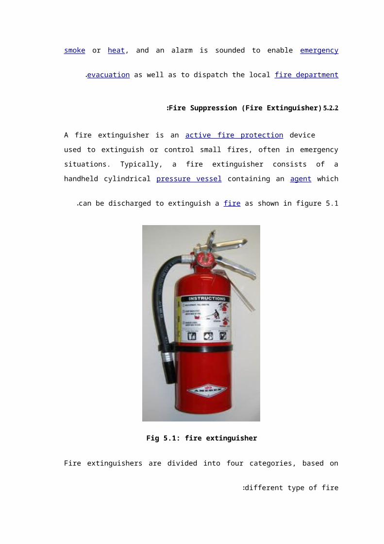
5.2.2 Fire Suppression (Fire Extinguisher):
A fire extinguisher is an active fire protection device used to extinguish or control small
fires, often in emergency situations. Typically, a fire extinguisher consists of a handheld
cylindrical pressure vessel containing an agent which can be discharged to extinguish a fire as
shown in figure 5.1 .
Fig 5.1: fire extinguisher
Fire extinguishers are divided into four categories, based on different type of fire :
1- Water extinguisher or air pressurized water (APW) are suitable for class A fire
only . Never use a water extinguisher on grease fires , electrical fires or class D
fires .water extinguisher are filled with water and pressurized with oxygen . The
best way to remove heat is to dump water on the fire but .
2- Dry chemical extinguisher come in a variety of type and are suitable for a
combination of class A , B and C fires . These are filled with foam or powder
and pressurized with nitrogen. Dry chemical extinguisher interrupt the chemical
reaction of fire by coating the fuel with a thin layer of powder, separating the
fuel from the surrounding oxygen.
3- Carbon dioxide (CO2) extinguisher are used for class Band C fires. CO2
extinguisher contain carbon dioxide, a non flammable gas, and are highly
pressurized , The pressure is so great that it is not uncommon for bits of dry ice
to shoot out the nozzle . They don’t work very well on class A fires because they
may not be able to displace enough oxygen. to put the fire out , casing to re-
ignite .
Fire needs fuel, oxygen and heat in order to burn. Fire extinguisher remove one of these
element by applying an agent that either cools the burning fuel or remove the surrounding
oxygen.
Using the Fire Extinguisher:
At the top of the cylinder, there is a smaller cylinder filled with compressed gas . A
release valve acts as a locking mechanism and prevent this gas from escaping . When pull the
safety pin and squeeze the lever, the lever pushes on acting rod which prices the valve down
to open passage to the nozzle. The compressed gas is released , applying a downward pressure
on the fire extinguishing material .This pushes the material out the nozzle with high amounts
of the pressure.
Although there are many type of the fire extinguisher, all of them operate in a similar
manner: Pull the pin at the top of the fire extinguisher the pin release a locking mechanism
and will allow you to discharge the extinguisher. Aim of the base of the fire this important in
order to put out of the fire you must extinguish the fuel. Squeeze the lever slowly this will
release the extinguishing agent in the extinguisher. If handle is released the discharge will be
stop.
Sweep from side to side using sweeping motion, move the fire extinguisher back and
forth until the fire is completely out. Operate the extinguisher from safe distance, several fit
away and then move towards the fire once it start to diminish .
Fire extinguisher care maintenance:
There are a different between the a fire extinguisher maintenance and the fire
extinguisher inspection the inspection is a quick check to give reasonable assurance that the
fire extinguisher is available, fully charged and operable, the value of the inspection lies in the
frequency regularity with which it is conducted the frequency will vary from hourly to monthly,
based on the needs of the situation .
Inspection should always be conducted when extinguisher are initially placed in service
and there after approximately 30 day interval , but in maintenance fire extinguisher should be
maintained at regular intervals , or when specifically indicated by an inspection . Maintenance
is a thorough check of the extinguisher. It intended to give maximum assurance that an
extinguisher will operate effectively and safely. It includes a thorough examination and any
necessary repair. It will normally reveal the need for hydros .
In maintenance of the fire extinguisher must ensure that ;
The extinguisher is not blocked by equipment that cloud interferes with access in an
emergency .
The pressure is at the recommended level .
The nozzle or other parts are not hindered in any way .
Location of the Fire Extinguisher:
It recommended to have at least one fire extinguisher on each floor, also keep them in
plain sight and more than five feet above the floor . Don’t put them in closet because that will
coast valuable time when reaching for it. And even though a fire extinguisher may not match
décor don’t put it behind curtains or drapes .
The most important places to have a fire extinguisher are in areas that are more
susceptible to fire .
There are two main types of fire extinguishers: Stored pressure ,Generated pressure
5.2.3 Fire Detection (Smoke Detector):
A smoke detector or smoke alarm is a device that detects smoke and issues an alarm
to alert nearby people that there is a potential fire. A household smoke detector will typically
be mounted in a disk shaped plastic enclosure about 150mm in diameter and 25mm thick, but
the shape can be vary by the manufacturer as shown in figure 6.2.
Because smoke rises, most detectors are mounted on the ceiling or on a wall near the
ceiling. To avoid the nuisance of false alarms, most smoke detectors are mounted away from
kitchens. To increase the chances of waking sleeping occupants, most homes have at least one
smoke detector near any bedrooms; ideally in a hallway as well as in the bedroom itself.
The detector comes in many types such as:
a. Optical detector:
An optical detector is a light sensor consists of optical chamber, cover, case molding,
photo diode, infra red LED as shown in the figure 6.3. When used as a smoke detector it

includes a light source (infra-red LED), a lens to collimate the light into a beam, and a
photodiode or other photoelectric sensor at right-angles to the beam as a light detector .
In the absence of smoke, the light passes in front of the detector in a straight line. When
smoke enters the optical chamber into the path of the light beam, some light is scattered by
the smoke particles, and some of the scattered light is detected by the sensor. An increased
input of light into the sensor sets off the alarm. Another type works by using a straight line
infra-red beam from the sender to the receiver. When smoke enters the beam, some light is
scattered which results in less light detected by the receiver .
b. Ionization detector:
This type of detector is cheaper than the optical detector; however it is sometimes rejected
for environmental reasons. It can detect particles of smoke that are too small to be visible. It
includes a tiny mass of radioactive americium-241, which is a source of alpha radiation. The
radiation passes through an ionization chamber, which is an air-filled space between two
electrodes, and permits a small, constant current to
flow between the electrodes .
Fig (5.3) optical detector
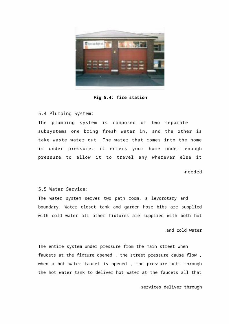
5.3 Fire Station:
A fire station is a structure or other area set aside for storage of firefighting apparatus
(i.e., fire engines and related vehicles), personal protective equipment, fire hose, fire
extinguishers, and other firefighting equipment. It may also have dormitory living facilities and
work areas such as meeting rooms, workshop, or laundry .
In a one floor station, a tower like structure is sometimes used specially for hose hanging.
An occupied station will usually have a station alarm system for receiving and annunciating an
alarm, and indications of where and what caused the alarm. However, sometimes the only
"alarm" is a telephone that is rung in case of emergency.
In a more structured operation, full-time or on-call volunteer or career firefighters staff
the station some or all of the time. There may be office space for the officers, a library of
reference and other materials, and a "trophy wall" or case where the firefighters display
memorabilia.
Activities in a fire station include regular inspection and cleaning of the apparatus and
equipment, and continuing education in the fire service. Weekly or bi-weekly routine typically
includes various drills in which firefighters practice their skills. Some fire companies also host
public activities at the fire station during annual "fire prevention week" or similar, and the
facility may also be used for fund-raising by the "firemen's association", "fire buffs", or "fire
auxiliary".
The approaches to a fire station are often posted with warning signs, and there may be a
traffic signal to stop traffic when apparatus are leaving or returning to the station .
Fig 5.4: fire station

5.4 Plumping System:
The plumping system is composed of two separate subsystems one bring
fresh water in, and the other is take waste water out .The water that comes
into the home is under pressure. it enters your home under enough pressure to
al low it to travel any wherever else it needed .
5.5 Water Service:
The water system serves two path room, a levorotary and boundary. Water closet tank
and garden hose bibs are supplied with cold water all other fixtures are supplied with both hot
and cold water.
The entire system under pressure from the main street when faucets at the fixture
opened , the street pressure cause flow , when a hot water faucet is opened , the pressure acts
through the hot water tank to deliver hot water at the faucets all that services deliver
through.
In water service we used the; pipe tubing, fitting, valve, expansion, shock pipe support and
expansion. To illustrate this element:
1-Pipe tubing and fittings:
The terms pipe and tubing can be used interchangeably however copper is usually
referred to as tubing and other material refereed as a pipe, for water distribution possible
choices are galvanized steel, brass, copper and plastic. Because of tendency to corrosion
galvanized steel is used much less than copper and plastic. Notice that the plural form plastic is
used rather than the singular plastic .The reason is that a number of differing plastic materials
are used .
2-Fittings and valves:
Steel fitting and pipe are connected by threads but copper tubing and its fitting are
connected by sliding fit and in plastic joints a solvent weld or heat fusion is used.
3-Expansion and shock:
In closed system an increase in a water temperature could burst a pipe or open the hot
water relief valve method to solve this problem capped air champers is used small bubbles of
air are trapped in all water they collect and remain in the chambers this air provides a cushion
against expansion and also against dynamic shock.

4-pipe support and expansion:
This illustrates shows pipe support methods in heavy construction but in wood frame
construction perforated metal straps are suitable.
5.6 Domestic Hot Water Heaters:
There are many different methods of heating, storing and distributing domestic hot
water. One of the methods, a tankless coil that eliminates the tank, depending on the size of
the coil, it can deliver between 3to 15 gallons per minute (gpm) at 100F rise in temperature.
An aquastat in the boiler water at the location of the coil turns on the gas fire if the water
temperature drops.
Aqua stat setting could be deliver at about 180F, the domestic water would then be delivered
at about 160F ,a 100F rise from a probable 60F cold water entering the coil.
Stored Hot Water:
This category, although the hot water is always stored in a cylinder or tank can be further
divided into three categories.
Immersion:
An immersion heater is an electric element which screws into the hot water tank .
This element is wired to the mains electrical supply via an isolating switch, a thermostat
to control the temperature, and sometimes a timer which enables you set the times you wish
to have the water heated. Using a timer, together with a well insulated tank, it is possible to
heat the water when electricity rates are at their cheapest and use it during the day. It is worth
remembering that the hot water from an immersion heater is always drawn from the top of
the cylinder, where it has risen over the cold water underneath (convection current). The cold
water, fed to the tank from underneath, gives the hot water the pressure it needs to leave the
cylinder, from the top, when required by the taps. Some tanks can contain two elements,
giving you a choice as to how much water you want to heat up at any one time.
It is quite rare nowadays for the immersion heater to be the only method of domestic
water heating in a home and the immersion is generally used as a back up to one, or both, of
the following two methods.

Direct boiler system:
With a direct system, the hot water may be stored in a square galvanized tank. The
principle is the same; another cold water pipe runs from the base of the cylinder to the boiler.
The boiler heats the water and returns it to the tank higher up. When hot water is drawn from
the tank, it is replaced by cold from the cold tank, which in turn is fed to the boiler. This is
direct heating of the water by either a) the immersion or b) the boiler. The hot water is simply
stored in the tank. To identify a direct water system you will find the end of the vent pipe fixed
above your cold water tank. This allows for any stem expansion in the cylinder to flow directly
into the cold tank and not damage the cylinder or cause air locks in the system.
Indirect boiler system:
With an indirect water system, the copper hot water cylinder contains a coil of pipe. This
coil forms part of a run of pipe work attached to the boiler. It is heated directly by the boiler.
Indirectly, it heats the water in the cylinder. The coil, or "heat exchanger" forms part of the
central heating circuit, and its water heating abilities are purely a by-product of its main
function, which is to heat the radiators.
This heating is called the "primary" circuit; the pipes running to and from the boiler are
called the primary flow and return. The hot water tank operates in exactly the same way as the
direct system.
To identify an indirect system, you will see two water tanks in your loft. The second,
smaller one is the feed for the primary circuit. It will top up the system when necessary and
will also have a vent pipe over the top. The level of water in this tank will be considerably
lower to allow the water to rise as it expands when it gets hot without overflowing. Both of the
boiler systems above are called "vented" systems. Because of this vent pie, they are open to
atmospheric pressure and operate as low pressure systems. They both call for cold water from
a cold tank stored, generally, in the roof space .
The unvented system operates purely from mains water. The principles of heating are the
same, but because everything is under the pressure of the mains water, flow rates are much
better...Many safety devices are built into this system to accommodate for the greater
pressure and expansion of the water. Although a small tank may be found in the loft for
venting and feeding your central heating, No cold water storage tank is necessary. Hot water
cylinder capacity varies between 25 gallons to 50 gallons for normal domestic supply, with the

larger being enough to supply an average family for a day. Most cylinders are made from thin
copper and you should make sure your cylinder is well lagged to prevent heat loss. Pre-lagged
cylinders are available, which are coated with foamed polyurethane.
5.7Cold Water Storage:
System and tanks, modifications to pipe and storage systems should take place so that
only one unit for continuous disinfection need be installed. Wherever possible the cold
water storage system and storage tanks should store water below 20°C. The Responsible
Person should eliminate the possibility of any conditions which produce abnormally high
temperature rises.
Advice should be sought on the method to be used to control any temperature
rise.
Cold water storage systems and tanks for wholesome water supply, shall be
installed and maintained in a workmanlike manner and, flushed and tested.
Disinfected is necessary before bringing into use as required by 'The Water
Supply (water fitting) Regulations It is essential that all cold water storage systems
and all storage tanks should be thoroughly cleaned out at least annually.
The cold water storage system is sometimes associated with pressurized vessels
and storage tanks, which should be disinfected as appropriate. All equipment should
then be drained to waste and the system refilled.
A continuous system of disinfection should be constantly maintained. An
official log book should be maintained by the Responsible Person and the readings
of disinfection effectiveness in the cold water storage system recorded daily.
At least once a week the Maintenance Team should examine and sign the
log book and in the event of the disinfection levels falling below the minimum
effective levels take appropriate action .Testing should be carried out using the
appropriate testing equipment and the Responsible Person should ensure that all
members of his staff are trained to carry out this test efficiently.
5.8 Distribution Pipe Sizing:
The sizing of a water distribution pipe system is achieved by establishing the anticipated
flow rates. In liters per second (L/s) taking account of the diversity of use of all the various types
and numbers of appliances, and equipment requiring a water supply connection In practical terms
all the water draw-off points are not in use at the same time. The actual number in use, in relation
to the total number capable of being used varies dependant on the occupational use in the various
types of building.
The supply water in building depends on the application are used in the building as shown
in` table (6.1) below.
5.9 Plumping Fixture:
Toilets, sinks, and tubs are fixtures. In addition, an outside faucet is a fixture and so is a
washing machine. All devices that draw freshwater and discharge wastewater are fixtures, and
all are designed to keep the supply and drainage systems strictly segregated the fixture of the
toilet as shown in figure 5.6 below .
Some fixtures have individual supply shutoff valves so you don't need to close the
main shutoff to repair them. It's a good idea to make sure knows the location of the main
shutoff valve as well as how to use it. You may want to tag the main shutoff valve so anyone
can easily find it.
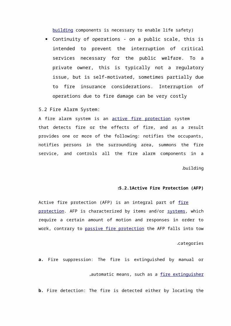
Figure 5.6: toilets fixture
5.10 Sample of Calculation:
5.10.1 Fire system:
In Amar tour there is 22 landing valve and 29 fire cabinet Distributors in the
building , in the floors from B-3 to F-3 there are 2 landing and 3 fire cabinet in each floor
and from F-4 to F-8 there are 2 landing and 2 fire cabinet.
This fire equipment is located at exit stairways and in each exit passageway at the
entrance from the building areas into the passageway.
There are 2 majour stand pipess in the building each riser size is 6 inch and a
minor stand pipe has a 6 inch.
Pump is selected to provide 750 gpm and 146.5 psi, the water must be
provide the further landing valve by 250 gpm and 100 psi.
Storage tank: the storage tank must be supply water for two hours by 750
gpm this tank capacity is 342
(750 gpm = 2850 ( )2850*2*60/)1000 = 342
5.10.2 Drainage system:
Any horizontal branch contain shower or lavatory or both, and this branch
size is 2 inch
Any horizontal branch contain water closet(W.C) or floor drain(F.D) or
both ,and this branch size is 4 inch.
Any horizontal branch must be sloped in range (1-1.5)cm for every 100 cm.
The branches are connected in stack that’s size is 6 inch.
Every stack contain vent and this vent size is 6 inch.
Fixture Number of Fixture unit
Lavatory 3
Shower 2
Water closet 6
Sink 2
Urinal 6
Table (5.1): Fixture unit for Fixture.
The Fixture unit for lavatory is 3 and the size equal(from the appendix) is 2’’.
5.10.4 Potable water:
The pipe size is calculating depend on fixture unit:
Fixture Number of Fixture unit(Public)
Lavatory 1.5
Shower 3
Water closet 10
Sink 2.25
Table (5.2) number of fixture unit
The Fixture unit for water closet is 10 and the flow rate equal(from the
appendix) 1.7 L/S then the size equal 1’’ (from the appendix) .
5.11 Summary:
In this chapter we defined all components of fire alarm and plumping system, all these
systems are calculated and tabulated in this chapter.

Ch.6 pipe sizing and duct design :
6.1 introduction for pipe sizing:
Piping network are used to transmit hot water from boiler to the fan coil units in order to heat
the air, and also it transmit the cold water from the chiller to the fan coil units in order to cool
down the air.
6.2 Pipe sizing:
The main pipe that come out from the boiler was calculated at the total Heating load, and the
main pipe that come out from the chiller was calculated according to the total cooling load,
but since the fan coil units are installed for both cooling and heating, then the pipes that
entering at the fan coil units was size according to the cooling load since the pressure head and
the mass flow rate is bigger than heating load.
6.3 Design procedures:
1- The total cooling load was calculated for the floor(Latent and sensible).
2- The mass flow rate for the water calculated.
3- The pressure head was estimated in (Kpa) from A.22.
4- The longest loop from the boiler to the far fan coil unit and return to the boiler was
calculated multiplying by (1.5) due to fittings.
5- The pressure head per unit length is calculated and it should be between range from
(200< ∆p/L<550).

6- Then the diameter of pipe entering to the floor is estimated from A.23.
6.4 Sample of calculation:
- The main diameter that come out from the boiler:
The total Heating load is
The total mass flow rate =
The pressure head per unit length is = 200 pa/m

Table(6.1) Size for pipe.
*And from table above the size equal 3.5. ’’
-And the main diameter that is come out from the chiller is calculated by:
SizeFlow Rate (up to)
M3/s gal/min
(1/2") 15 mm 0.11 1.744
(3/4") 20 mm 0.23 3.646
1" 25 mm 0.44 6.974
1( 1/4") 32 mm 0.90 14.265
1( 1/2") 40 mm 1.40 22.190
2" 50 mm 2.20 34.871
2( 1/2") 65 mm 4.20 66.571
3" 80 mm 7.90 125.218
3( 1/2") 100 mm 16.00 253.605
4" 125 mm 29.00 459.660
4.5" 150 mm 48.00 760.816

The total cooling load is
The total mass flow rate =
The pressure head per unit length is = 200 pa/m
*And from table (6.1) the size equal 3.5. ’’
Piping for the fan coil at the first basement in the control lab is estimated by:
The cooling load for gallery shop (4) in the ground floor is 13088.492 W.
The mass flow rate is
The pressure head per unit length is equal to 600 pa/m
*And from table (6.1) the size equal 1. ’’
6.5 introduction for ducts:
Since the air handing unit could be installed far away from the conditioned space, the duct net
works are used to transport heated or cooled air from the air handing units to the air
conditioned space, and it return the air from the space to the units or to outside.

The ducts are installed above the false ceiling, so it doesn’t affect on the esthetic view inside
the conditioned space.
Figure (6.1) Rectangular Ducts
6.6 Types of Air Duct:
[A]Air ducts can be classified into four types according to their transporting functions:
1 .Supply duct. Conditioned air is supplied to the conditioned space.
2 .Return duct. Space air is returned (1) to the fan room where the air-handling unit is installed
or
(2 )to the packaged unit.
3 .Outdoor air duct. Outdoor air is transported to the air-handling unit, to the fan room, or to
the
space directly.
4 .Exhaust duct. Space air or contaminated air is exhausted from the space, equipment, fan
room,
or localized area.

[B ]Air ducts can also classified into the shape as shown below.…
FIGURE (6.2) Various types of air duct: (a) rectangular duct; (b) round duct with spiral seam; (c) flat oval
duct; (d) flexible duct.
6.7 Theory background:
Air like other fluid, it faces retardation force called drag force, so ducts need pressure rise in
order the air be able to flow inside the ducts., because the drag force which acting on the air
flow produces pressure loss of the flow.
Duct systems can be classified according to the maximum pressure difference between the air
inside the duct and the ambient air (also called the static pressure differential) as _0.5 in. WC
(_125 Pa), _1 in. WC (_250 Pa), _2 in. WC (_500 Pa), _3 in. WC (_750 Pa), _4 in. WC
_(1000 Pa_ ,)6 in. WC (_1500 Pa), and _10 in. WC (_2500 Pa). In actual practice, the maximum
pressure difference of the supply or return duct system in commercial buildings is usually less
than _3 in. WC (_750 Pa).
In commercial buildings, a low-pressure duct system has a static pressure differential of 2
in.WC (500 Pa) or less, and the maximum air velocity inside the air duct is usually 2400 fpm (12
m/ s). A medium-pressure duct system has a static pressure differential of 2 to 6 in. WC (500
to1500 Pa) with a maximum air velocity of about 3500 fpm (17.5 m / s). In industrial duct
systems, including mechanical ventilation, mechanical exhaust, and industrial air pollution
control systems, the pressure difference is often higher. In residential buildings, the static
pressure differential of the duct systems is classified as _0.5 in. WC (_125 Pa) or _1 in. WC
(_250 Pa). The joints of rectangular ducts have a comparatively greater percentage of air
leakage than factory-fabricated spiral-seamed round ducts and flat oval ducts, as well as
fiberglass ducts. Unsealed rectangular ducts may have an air leakage from 15 to 20 percent of
the supply volume flow rate. Rectangular ducts are usually used in low-pressure systems.
The ratio of the long side a to the short side b in a rectangular duct is called the aspect ratio
Ras. The greater Ras, the higher the pressure loss per unit length as well as the heat loss and
heat gain per unit volume flow rate transported. In addition, more labor and material are
required. Galvanized sheet or, more precisely, galvanized coated steel sheet, and aluminum
sheet are the materials most widely used for rectangular ducts. To prevent vibration of the
duct wall by the pulsating airflow, transverse joints and longitudinal seam reinforcements are
required in ferrous metal ducts.
6.8 Duct sizing:
Duct sizing determines the dimensions of each duct section in the air duct system. After the
duct sections have been sized, the total pressure loss of the air duct system can then be
calculated, and the supply, return or relief fan total pressure can be calculated from the total
pressure losses of the supply and return duct systems and the pressure loss in the air-handling
unit or packaged unit.

Equal pressure drop method:
This method sizes the air duct so that the duct friction loss per unit length _pf,u at various duct
sections
always remains constant. The final dimensions of sized ducts should be rounded to standard
size. The total pressure loss of the duct system _pt, in in. WC (Pa), equals the sum of the
frictional losses and dynamic losses at various duct sections along the critical path:
_pt _ _pf,u[(L1 _ L2 _ _ _ _ _ Ln) _ (Le1 _ Le2 _ _ _ _ _ Len)]
where L1, L2, . . . , Ln _ length of duct sections 1, 2, . . . , n, ft (m)
Le1, Le2, . . . , Len _ equivalent length of duct fittings in duct sections 1, 2, . . . , n, ft (m)
Design procedures:
- Grills and diffusers are calculated and distributed uniformly.
- The total sensible heat of floor is calculated.
- The ( V) circulation of floor is calculated.
- The initial velocity is 5 m/s.
- The pressure drop (∆P/L) is determined from A.21 ( by using velocity and Vcirculation).
- The main diameter is calculated from A.21. at the same (∆P/L).
- The height and width of the rectangular ducts are determined from A.24.
6.9 Sample Calculations:
For gallery shop (4) in the ground floor:
Equal:
1- Q(sensible) transitions Through south eastern wall =
=0.755*65.826*9 = 245.4 W

2- Q(sensible) Conduction Through south eastern wall =
=0.755*65.826*8 = 397.589 W.
3- Q(sensible) transitions Through south eastern Glass =
=34.344*439*0.9*0.49 =6648.964 W
4- Q(sensible) convection Through east Glass =
=34.344*3.5*5 = 601.02 W.
5- Q(sensible) due to people =
=7*71.5*0.49 = 245.245 W.
6- Q(sensible) due to Lighting =
=931.484 W.
7- Q(sensible) due to Devices =
=124.3 W
8- Q(sensible) due to Ventilation =
=1.2*159.228*8 = 1528.5888 W.
From A.12 Duct Diameter = 0.285m.
Related Documents