USER MANUAL / BRUKSANVISNING / GUIDE D’INSTRUCTIONS / BEDIENUNGSANLEITUNG English Manual for OriLink® WinTools, Rev R10, 180409 OriLink® WinTools Software for Monitoring System Manual Version 10 (Most is valid also for older versions) 23 413 Basic version 23 414 Professional version

Welcome message from author
This document is posted to help you gain knowledge. Please leave a comment to let me know what you think about it! Share it to your friends and learn new things together.
Transcript

USER MANUAL / BRUKSANVISNING / GUIDE D’INSTRUCTIONS / BEDIENUNGSANLEITUNG
English Manual for OriLink® WinTools, Rev R10, 180409
OriLink® WinTools
Software for
Monitoring System
Manual
Version 10
(Most is valid also for older versions)
23 413 Basic version
23 414 Professional version
2(96)
1. INTRODUCTION 6
2. TECHNICAL DEMANDS 6
3. DIFFERENCE BETWEEN BASIC AND PROFESSIONAL VERSION 6
3.1. BASIC VERSION 6 3.2. PROFESSIONAL VERSION 6
4. INSTALLATION 7
4.1. WINTOOLS BASIC SOFTWARE INSTALLATION 7 4.2. CONVERT BASIC VERSION TO PROFESSIONAL VERSION (REGISTER) 7 4.3. CHOOSE THE LANGUAGE. 8 4.4. ODBC ADDITIONAL INFORMATION 10 4.5. COM PORT SET-UP FOR IMPROVED PERFORMANCE. 11
4.5.1. FIFO READ-buffer in Windows NT. 11 4.5.2. FIFO READ-buffer in Windows 98SE or later 11
4.6. INSTALLING ORILINK® WINDB MANAGER (PROFESSIONAL ONLY) 12 4.6.1. In older versions. 12 4.6.2. In newer versions (R10 or later) 12
4.7. CHECK FOR LATE UPDATES 12
5. ORILINK® ENGINE 13
5.1. UPDATE PNP ARRAY 14 5.2. ORILINK® NEIGHBOURHOOD 15 5.3. STOP ENGINE 15 5.4. PROPERTIES 15 5.5. RUN 17
6. ORILINK® NEIGHBOURHOOD 18
6.1. START 18 6.2. TECHNICAL DESCRIPTION 18 6.3. NEIGHBOURHOOD MENU (R6) 18 6.4. NEIGHBOURHOOD MENU (R7 OR LATER) 19 6.5. QUICK STATUS INFORMATION 19 6.6. PASSWORD PROTECTION 19 6.7. MPDM (23 400) 20
6.7.1. Optional connector 20 6.7.2. Host Properties 20 6.7.3. Port(n) properties. 21 6.7.4. MPDM change address. 22 6.7.5. MPDM Reboot module. 22
6.8. KEYPAD (23 401) 23 6.8.1. Edit Fast Menu 23 6.8.2. KP properties. 23 6.8.3. KP change address. 25 6.8.4. KP Reboot module. 25
6.9. PRINTER MODULE (23 402) 26 6.9.1. Printer interface and database. 26
6.9.1.1. Transactions 26 6.9.1.2. Users 27 6.9.1.3. Job number 27 6.9.1.4. Edit Receipt 28 6.9.1.5. Edit Report 29
6.9.2. Tank properties 29 6.9.3. PM change address 29
6.10. SERIAL INTERFACE (23 403) 30 6.11. LED DISPLAY (23 404) 30
6.11.1. LED Properties. 30 6.11.2. LED Change address. 30 6.11.3. LED Manage presets, only LED101. 31 6.11.4. LED Reboot module. 31 6.11.5. REEL Host properties, only for LED101. 31 6.11.6. REEL Properties, only for LED101. 31
6.12. CLOCK MODULE (23 405) 32

3(96)
6.13. TANK CONTROL MODULE (23 408) 33 6.13.1. Valve symbol 33 6.13.2. Discrete level sensor symbol 33 6.13.3. Analogue level sensor symbol 33 6.13.4. TCM Setup menu 33
6.13.4.1. Host properties 34 6.13.5. Port[n] properties 34 6.13.6. Change address 35 6.13.7. Reboot 35
7. LOADING ORILINK® SERVICES 36
7.1. TIME SYNCHRONISATION (CLOCK.DLL BASIC AND PROFESSIONAL) 36 7.1.1. Loading the Clock Service 36
7.2. PC AS DATABASE (WINDB.DLL ONLY PROFESSIONAL) 37 7.2.1. Loading WinDB service 37 7.2.2. Set-up a dispense point to use PC database 38
7.3. SCRIPT SERVICE (SCRIPT.DLL ONLY PROFESSIONAL) PART NUMBER 23475 38 7.4. MESSAGING SERVICE (MESSAGIN.DLL ONLY PROFESSIONAL) PART NUMBER 23481 38 7.5. DBDOCKING SERVICE (DBDOCKS.DLL ONLY PROFESSIONAL) PART NUMBER 23477 39
8. USING THE WINDB MANAGER SOFTWARE. 40
8.1. OBSERVE ! 40 8.2. START 40 8.3. CHANGING USER PASSWORD 40
8.3.1. Chose if the main window should be sizable or not 40 8.3.2. Changing user password 41 8.3.3. Changing management password 41 8.3.4. How to disable the login form. 41
8.4. VIEW MENU 42 8.4.1. Transaction and Transaction table 42 8.4.2. Operator details 42 8.4.3. Tank Stock update history 43 8.4.4. Tank Message history 43 8.4.5. Db Docking Service transaction table 43
8.5. MANAGING MENU 44 8.5.1. WO- numbers 44 8.5.2. Operators 44 8.5.3. Tanks 46 8.5.4. Printing 48 8.5.5. Preset Codes 49 8.5.6. Suppliers 49 8.5.7. Administrator 50
8.6. REPORT MENU 50 8.6.1. Input WO-number example. 50 8.6.2. Input dates example 50 8.6.3. System reports 50 8.6.4. Totals 51 8.6.5. Periodical 51 8.6.6. Combined 52
8.7. WINDOW MENU 52 8.8. HELP MENU 52 8.9. CLOSE THE PROGRAM 52
9. HWFLASH TOOL (HWFLASH.EXE) 53
9.1. HOW TO CHANGE THE SYSTEM LANGUAGE (R7 OR LATER) 53 9.2. HOW TO UPDATE CHIP SOFTWARE AND/OR LANGUAGE FOR MODULES. 55 9.3. HOW TO CHANGE A FLASH CHIP FROM MODULE TYPE TO CO TYPE. 57 9.4. HOW TO UPDATE TO FLASH CHIP TECHNOLOGY (R7 OR LATER). 58
9.4.1. If the flash chip already contains module software. 58 9.4.2. If the flash chip comes with only CO software (part number 23482). 58
9.5. SET MODULES TO PRODUCTION DEFAULT (R7 AND LATER) 60
10. ERROR HANDLING. 61

4(96)
10.1. ORILINK® GENERAL ERROR TOOL 61 10.2. ORILINK® BASIC WINTOOLS ERRORS 61 10.3. ORILINK® PROFESSIONAL VERSION ERRORS 62 10.4. ODBC-KEY ERRORS 62 10.5. WINDB MANAGER ERRORS. 63 10.6. SERVICE AND OCP ERRORS 63
11. ADVANCED FEATURES 65
11.1. MODULE PNP UPDATE PRIORITY (LARGE SYSTEMS). 65 11.2. CHANGE LANGUAGE FOR MODULES BY A COMMAND 66 11.3. SET MODULES TO PRODUCTION DEFAULT BY A COMMAND 67 11.4. OLSET.EXE, COMMAND LINE TOOL. 69 11.5. CREATING SUBMENUS IN THE ENGINE CONTROL MENU 70 11.6. DESIGN A CUSTOM SYSTEM GRAPHIC LAYOUT (HWMON2) 70
11.6.1. Create a new layout file. 70 11.6.2. Edit a layout. 73 11.6.3. Modifying the layout background 75 11.6.4. Open a custom layout file 77 11.6.5. Creating a Client layout file. 78
11.7. ORION COMMON PLATFORM (OCP) 79 11.7.1. Different ways of connections 79 11.7.2. How does it work 79 11.7.3. Existing OCP-drivers (040924) 79 11.7.4. How to install an OCP-driver 79 11.7.5. How to load an OCP-driver 80
11.8. ORILINK® SERVER-CLIENT SET-UP. 81 11.8.1. Install the software on Server 81 11.8.2. OriLink® Server set-up (Windows98SE) 82 11.8.3. OriLink® Server set-up (Windows NT/2000/XP SP1) 83 11.8.4. OriLink® Server set-up (Windows XP SP2) 83 11.8.5. OriLink® Client Set-up. 84 11.8.6. Start Up. 84
11.9. IMPORTING DATA TO MICROSOFT EXCEL 84 11.10. USING MS ACCESS 86 11.11. SCRIPT SERVICE 23475, SCRIPT.DLL (PROFESSIONAL ONLY) 86
11.11.1. How does it work? 86 11.11.2. What kind of script language is used 87 11.11.3. How to write scripts 87
12. USING MPDM AS TCM100 (SIMPLE TANK CONTROLLER) 87
13. USING MPDM/TCM AS A PLC (PROGRAMMABLE LOGIC CONTROLLER) 88
13.1. POSSIBLE INPUTS / OUTPUTS 88 13.2. SUPPORTED OPERATIONS 88 13.3. SAMPLE PLC CODED FUNCTIONS 88
13.3.1. Activate p4o with p4a for 60 s use r1 88 13.3.2. Activate p4o with p4a for 10 s, if p4b is OFF Use r1 and deactivate p4o 88 13.3.3. Flipp-flopp for p3o 89 13.3.4. Timed cascade coupling of Port1. 89 13.3.5. Start a pump p4o if the system is opened and activate p3o if it is closed 89 13.3.6. Start control for a system with two pumps 89 13.3.7. Simple analogue controller with hysteresis 89 13.3.8. Equip MPDM and or TCM with PLC chip software 89
13.3.8.1. PLC100 (a MPDM flashed with PLC100 software) 90 13.3.8.2. PLC200 (a TCM flashed with PLC200 software) 90
14. CYCLIC DISPENSE MODE 91
14.1. HOW TO GET A WARNING SIGNAL FOR FAILED DISPENSE. 91 14.2. HOW TO GET A RECORD/REPORT OF DISPENSES. 92
15. PRE-PROGRAMMED AMOUNTS WITH A MPDM 92
15.1. CONNECT A MPDM TO DISPENSE PRE-PROGRAMMED AMOUNTS 92 15.2. CONFIGURE A MPDM TO DISPENSE PRE-PROGRAMMED AMOUNTS 92 15.3. STATUS INFORMATION 93

5(96)
15.4. START, STOP AND RESET FUNCTION. 93
16. USE SOME REELS FOR PRESET (R10 ONLY) 94
17. UPDATING THE PC COMPUTER 95
18. PATCH THE OS TO THE LATEST VERSION 95
19. INSTALL / UPDATE MDAC 95
20. INSTALL / UPDATE MSJET 95
21. SHOW HIDDEN FILES AND EXTENSIONS 96

6(96)
1. Introduction
The OriLink® WinTools software is used mainly for four things,
1. Management and set-up of an OriLink® system using a PC computer.
2. Using a PC computer as database for fluids, users, transactions, job numbers, etc.
3. Connections to customer mainframe and DMS systems.
4. Customer tailored functions using scripting.
The software is modularised like the OriLink® hardware. This enables the possibility to only use functions needed and by
this have software that has lowest possible complexity.
2. Technical demands
To install and use this software the following is needed.
An OriLink® system.
A PC computer with properly installed and configured Microsoft Windows 95 /98SE /NT4 /2000 / XP Professional operating
system. It is recommended that the OS should be patched to the latest level.
Windows 98 /ME / XP Home are not tested or supported by us but there are no reasons for them not to work.
The PC should have a performance suitable for the used Operating system.
For the OriLink® WinTools the,
Minimum demands are Intel Pentium 2 333Mhz compatible, Windows95 and 128Mb RAM.
Recommend demand is a standard PC of today.
General rule -More things running in the PC needs higher performance.
MDAC 2.5 or later should be installed, (Microsoft Data Access Component).
MSJET should be installed, (Microsoft database drivers).
The PC must have one free 16550 compatible serial port. If it is a laptop without a serial port, use a PC-card to serial port
adapter, USB to serial port adapter is not recommended. If a USB to serial port adapter must be used chose one based on the
FTDI or Prolific chip set and use their reference drivers.
An OriLink® PC-interface (SIO part number 23 403)
A null-modem serial cable (part number 203 02 80), included in part number 23 403.
3. Difference between Basic and Professional version
The installation CD is the same for both versions and when you install the software both versions is installed.
3.1. Basic version
The basic version is mainly for graphic visualising of the OriLink® system on a PC. It can be used to set the time,
update tank levels, make a scheduled simple text file dump of transactions and for synchronisation of the time with
the PC. The basic version can be installed on several PC computers.
3.2. Professional version
To convert the basic version to professional version a registration is needed. A unique registration must be done for
each PC computer.
The professional version is needed if,
The PC should be able to act as the database
The PC should be used for configuration of the OriLink® system
Connection to an economic system (DMS) should be used
Customer tailored functions should be used
Multiple receipt printing should be used.
Script service should be used.

7(96)
4. Installation
Insert the OriLink® WinTools CD in the CD reader of the PC computer. Start Windows Explorer open the CD folder.
4.1. WinTools basic software installation
Go to the folder \OLWT and double click Setup.exe or
run the “OriLink WinTools Rnnn.exe”. Follow the
instructions on the screen.
Click Next to make a typical installation (default).
It is recommended to use C:\OriLink as installation
folder (default).
Restart the PC computer.
Click Start button (lower left corner of screen)
Choose Programs
Choose OriLink
Click Engine
The following window or similar will appear.
A small icon will also appear in the Info tray, lower right corner of screen,
indicating that the OriLink® engine is running. Double-click it and the engine
window will be shown and right-click it to show the engine menu.
Clicking the X tab in the upper right corner of the window closes the Engine window. It
does not shut down the engine.
The basic software installation is now finished.
4.2. Convert BASIC version to Professional version (Register)
To convert the software from BASIC to PROFESSIONAL a registration is needed.
The direct mail and
Online Registration
is not supported for
now.
When the OK on
the OK button
becomes black
click on the button
and the following
window will
appear.
Fill in the information
of the company that is
going to use the
software and mark the
choice “Save on disk”.
To register run the
program
LICENSER.EXE in the
main OriLink® folder
(default is C:\OriLink).
A window will appear.

8(96)
Choose a save destination, do not change file name, click Save button.
E-mail or post the license.lic file and information about what services
and/or OCP-driver you want to use to
E-mail: [email protected] Post: Alentec & Orion AB OriLink® Support Team Grustagsvägen 4 SE-138 40 Älta SWEDEN
The Licenser.exe can be run on the PC that should be used prior to the installation.
NOTE! If this is done, do not run it from a root folder (C:\, A:\,……..). Create a folder (C:\LIC, A:\LIC,….)
copy Licenser.exe to this folder and run it.
You will receive a validated license file “License.dat” copy this to the OriLink® folder
(default is C:\Orilink). If you get the license file by E-mail the name will be “License.ooo”
then rename it to “License.dat”.
Restart the engine.
The engine window will now look something like this
4.3. Choose the language.
For OriLink® WinTools version 6 or later the language for the Engine, the WinDB Manager and the modules are
controlled by the Orilink.ini and the Lang.lan files located in the C:\Orilink folder.
There are three different ways to set the system language.
Either open the Orilink.ini file in the folder you have installed OriLink® to, default is C:\Orilink, using Notepad
and edit the following
[Language]
PreferedLanguage=English
Or,
use Ollang.exe
Or,
use HWFlash.exe.
and select the preferred language. See chapter “9.1
How to change the system language “ or chapter “11.1.
Change language for modules”.
If your language does not exist and you want it added
use the “OriLink® R10 Translator.xls”. Use this even
if you have some earlier version of OriLink®.
9(96)
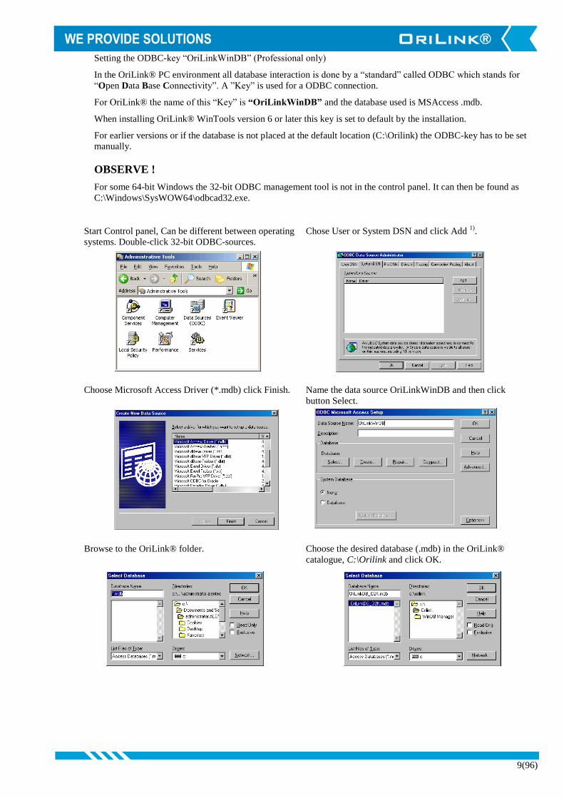
Setting the ODBC-key “OriLinkWinDB” (Professional only)
In the OriLink® PC environment all database interaction is done by a “standard” called ODBC which stands for
“Open Data Base Connectivity”. A ”Key” is used for a ODBC connection.
For OriLink® the name of this “Key” is “OriLinkWinDB” and the database used is MSAccess .mdb.
When installing OriLink® WinTools version 6 or later this key is set to default by the installation.
For earlier versions or if the database is not placed at the default location (C:\Orilink) the ODBC-key has to be set
manually.
OBSERVE !
For some 64-bit Windows the 32-bit ODBC management tool is not in the control panel. It can then be found as
C:\Windows\SysWOW64\odbcad32.exe.
Start Control panel, Can be different between operating
systems. Double-click 32-bit ODBC-sources.
Chose User or System DSN and click Add 1)
.
Choose Microsoft Access Driver (*.mdb) click Finish. Name the data source OriLinkWinDB and then click
button Select.
Browse to the OriLink® folder. Choose the desired database (.mdb) in the OriLink®
catalogue, C:\Orilink and click OK.

10(96)
Click OK Click OK.
If it is done correctly a data source with the name OriLinkWinDB is shown in User or System DSN. To decide if the
OriLinkWinDB should be set-up in User-DSN or System-DSN it must be decided if only one user should be able to
use the software or if every user should be able to do it. This decision is very important if the OS is Windows NT/
2000/ XP or later, because of the much higher level of security.
User-DSN Enables it to the user that is logged in when it is set-up.
System-DSN Enables it to all users, mostly used.
4.4. ODBC additional information
In systems with a high database load that is “a lot of database activities at the same time” like for intense
production systems and similar, you can sometimes see things like “No available database resources”. This can
be fixed by increasing the number of possible simultaneous threads to the database.
Open the ODBC
manager as above
and select the
ODBC you want to
change.
Then click
<Configure>
A window
like this will
be shown,
assuming
that you
want to
change the
OriLinkWin
Db key.
Now click
the <Advanced> button,
and a window like this
comes up.
Scroll options down to
the bottom.
And edit the thread value
to for example 6.
Now click <Ok>, <Ok>,... until you have left the
manager.

11(96)
4.5. Com port set-up for improved performance.
The RS-232 Com port for a PC can be based on many different controller chips (UART) but they all have some
common features.
The feature that is interesting for the performance of the OriLink® system is the communication FIFO buffers, in
particular the READ-buffer.
The READ-buffer works like this. When it is full the serial port controller chip (UART) sends a request to the
operative system (OS) (Windows) that it has data that needs to be handled. The OS passes the data to the targeted
software (OriLink® engine).
Normally today the READ-buffer is set to 14 (default for 16550 compatible UART) which means that the serial port
must receive 14 bytes before it calls the OS.
The OriLink® system is a Real-Time software that wants information in Real-Time and an UART FIFO READ-
buffer of 14 can sometimes cause unnecessary delays, especially when a connection to the workshop DMS system is
used.
Because of this it is recommended to set the FIFO READ-buffer of the used Com: port to 1.
4.5.1. FIFO READ-buffer in Windows NT.
Open the control panel then double click the “Ports” icon. Select the Com port used for OriLink from the shown list
and then Left-Click on the “Configure” button. Now Left-Click on the “More” button. A “Moore settings for
Com(n):” window is shown. In This window there is a check box called “FIFO activated”, uncheck this and Left-
Click the “OK”-button. Now the OS asks for a reboot. When the PC is rebooted it is done.
4.5.2. FIFO READ-buffer in Windows 98SE or later
First Right Click “This Computer” then select “Properties”. Left-Click the “Device manager” tab and a browser for
all hardware resources are shown. Left-Click the “+” sign in front of the “Ports (COM & LPT)” group. There will be
a list of available serial (Com) and parallel (Lpt) ports.
Right-Click on the one used for the OriLink® system and select “Properties”. Now Left-Click the “Port settings” tab
and then Left-Click the “Advanced” button.
Drag the READ-buffer slider all the way to the left and then Left-Click the “OK”-button.
12(96)
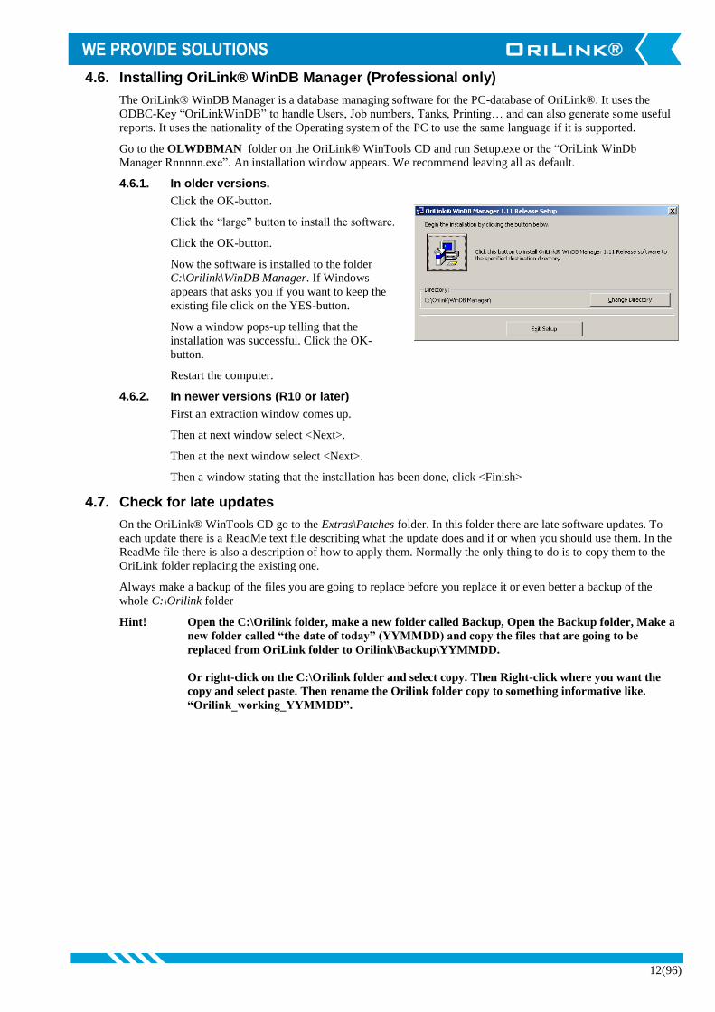
4.6. Installing OriLink® WinDB Manager (Professional only)
The OriLink® WinDB Manager is a database managing software for the PC-database of OriLink®. It uses the
ODBC-Key “OriLinkWinDB” to handle Users, Job numbers, Tanks, Printing… and can also generate some useful
reports. It uses the nationality of the Operating system of the PC to use the same language if it is supported.
Go to the OLWDBMAN folder on the OriLink® WinTools CD and run Setup.exe or the “OriLink WinDb
Manager Rnnnnn.exe”. An installation window appears. We recommend leaving all as default.
4.6.1. In older versions.
Click the OK-button.
Click the “large” button to install the software.
Click the OK-button.
Now the software is installed to the folder
C:\Orilink\WinDB Manager. If Windows
appears that asks you if you want to keep the
existing file click on the YES-button.
Now a window pops-up telling that the
installation was successful. Click the OK-
button.
Restart the computer.
4.6.2. In newer versions (R10 or later)
First an extraction window comes up.
Then at next window select <Next>.
Then at the next window select <Next>.
Then a window stating that the installation has been done, click <Finish>
4.7. Check for late updates
On the OriLink® WinTools CD go to the Extras\Patches folder. In this folder there are late software updates. To
each update there is a ReadMe text file describing what the update does and if or when you should use them. In the
ReadMe file there is also a description of how to apply them. Normally the only thing to do is to copy them to the
OriLink folder replacing the existing one.
Always make a backup of the files you are going to replace before you replace it or even better a backup of the
whole C:\Orilink folder
Hint! Open the C:\Orilink folder, make a new folder called Backup, Open the Backup folder, Make a
new folder called “the date of today” (YYMMDD) and copy the files that are going to be
replaced from OriLink folder to Orilink\Backup\YYMMDD.
Or right-click on the C:\Orilink folder and select copy. Then Right-click where you want the
copy and select paste. Then rename the Orilink folder copy to something informative like.
“Orilink_working_YYMMDD”.

13(96)
5. OriLink® engine
The OriLink® engine is the core of the WinTools software and it is the only thing that needs to be running. It acts as the link
between the hardware and software modules. The engine is controlled from its main window. All changes in the engine
should be followed by a restart of the system
Port: Shows the used serial port.
Packets/Bytes: Shows communication.
CS/FR/TO: Shows communication errors.
CS = Checksum
FR = Frame
TO = Time-out
Net Load: Shows load in OriLink® network
PC-side Clients: Shows number of total clients [Services clients]
(clients means graphic units and services)
No of modules: Shows number of hardware modules
Status: Shows if OriLink® hardware is connected to the set
Com port.
Version Shows version of the installed Engine
Lower right
corner
Shows the selected language, here English.
A small “O” icon will always be visible in the Info tray, lower right corner of screen,
indicating that the OriLink® engine is running.
In some Windows versions it can be hidden in the icon list and be shown by click on the icon
list expand symbol.
If the “O”-icon is double-clicked the engine window will be shown.
Clicking the X tab in the upper right corner of the Engine window closes the
Engine window but it does not shut down the engine.
To open the engine control menu “right-click” some were in the engine window
or on the “O”-icon in the Info tray. The result will be like this.
Below Properties menu item new items will be automatically added for services
loaded.
Below the line under Properties it is possible to add a personal Fast menu containing
the most used items. Se chapter “10.3 Creating submenus in the engine control menu”.
Typical things are workshop layouts, WinDb Manager, logs, ... and similar and can
look like this.

14(96)
5.1. Update PNP Array
The “Update PNP Array” tool is used to see a list of
hardware modules and some information about them.
The shown layout demands the use of engine.exe 107
or later.
After making changes to the system set-up, open this
and click the “Rescan” button to issue an order to
update the in PC memory stored PNP array.
The system will do this automatically but using the
“Rescan” button speeds it up.
Column Description Values Comment Applies to Pc demands
Address Module
address
1xxx,
2xxx,……
All modules and
module software
versions.
All OLWT versions.
Type Type of
module
MPDM100,
LED101,…….
Type +
Hardware/Feature
All modules and
module software
versions.
All OLWT versions.
Ver Software
version
TYPEXXXXX
(RCYY)
Flash chip
(18F452)
Version 6 with
engine update
version 107RC18 or
later.
Flags Functional
information
“O” Old PNP model Older chip versions Uncheck “Disable
PNP frame…” in
engine properties.
“N” New PNP model Latest OTP chip
versions (16C67)
Check “Disable PNP
frame…” in engine
properties if all
modules have this
flag.
“V” VERBS PNP model Flash chips
(18C452)
Version 6 with
engine update
version 107RC18 or
later.
”U” Unterminated Chip versions and
PCB versions that
support this.
OLWT Version 6 or
later
”T” Terminated Chip versions and
PCB versions that
support this.
OLWT Version 6 or
later
“L” Setup Lock jumper
off
MPDM’s and
LED’s with chip
versions and PCB
versions that
support this.
OLWT Version 6 or
later
“R” Clock module
present.
PM’s and LED’s
with chip versions
that supports this.
OLWT Version 6 or
later
Uptime Time since
last reboot
DD
HH:MM:SS
Flash chip
(18F452)
OLWT Version 6 or
later
BootReason Reason for
reboot
UnKnown Unknown error Flash chip
(18F452)
OLWT Version 6 or
later
Software When flashed
PowerUp Normal power on
WDT Module hang up
BOD Low voltage
Sleep Resume from sleep
mode
Reset Rest button pressed

15(96)
StackOverflow Software error
StackUnderflo
w
Software error
LastUpdate Time since
last PNP
update.
SS.decimals OLWT Version 6 or
later
NoUpdates Number of
PNP
updates.
XXXXXXX OLWT Version 6 or
later
In this list all modules of an OriLink® system should appear. If a module does not appear something is wrong. The
PNP support of the engine could be set in the wrong way, see 5.4 Properties. Other reasons could be modules with
the same address or wrong termination of the communication loop, see installation manual for OriLink®.
5.2. OriLink® Neighbourhood
The OriLink® Neighbourhood is a window that shows a graphic
representation of the system. Each individual part of the system
is shown as an icon and by right click an icon a control menu
appears. With this menu the actual unit could be controlled.
With the basic version normal day-to-day tasks can be carried
out and the other things can be shown. If the professional
version is used everything can be edited, this is then password
protected.
The default password is “2222” for OriLink® WinTools R7 or
later and “1111” for R6 and earlier. It can be edited in the
orilink.ini file
5.3. Stop Engine
By clicking on Stop Engine the engine together with the rest of the WinTools
software is shut down. To prevent shut down by mistake the shut down must
be verified by clicking the OK button in a window that is shown.
5.4. Properties
Properties are used to change the behaviour of the engine and to add
software modules called services and OCP drivers.
In the upper part of the properties window there is a frame named
“Communication”. First there is a list of possible communication ports.
If one in the list is double clicked it will update the Com Port parameter.
Next is the configured parameters that controls the communication
between the OriLink® system hardware and the WinTools software.
Parameters
Comport
Type the correct Com?:, default is Com1:. For laptops
without serial port use a PMCIA serial port card. The use
of a USB to serial port adapter is not recommended, it
can give random results.
Boost Priority
This is used to alter the PNP update priority for the PC. This should normally not be
changed, default is 40.
Disable Module Status Engine
This can be used to improve performance in systems were there is no need to see a
graphic representation of the OriLink® system. It removes the communication needed
for updating the graphic representation.

16(96)
Disable Broadcast Server
If this is enabled the OriLink® server can broadcast its existence in a network. This
makes it possible to run a hardware monitor such as HWMon2.EXE (OriLink®
Neighbourhood and customer layouts) on other PC’s in the network.
Disable “Frame PNP” e.g. Old Type
If all modules show “N” or “V”, when running update PNP array, this should be
checked.
If there are modules that show “O” it must be unchecked to make it possible to see these
modules on the PC.
Disable Client Timeouts
This controls if not accessible clients should be disconnected or not, this should
normally be unchecked.
Loaded Services
In the lower part of the properties window there is a frame named “Loaded Services”. This frame contains a
table of loaded services. In this window services can be added or removed.
Right-click the white window. Select service dll file and left-click Open-button.
Right-click a service and the service menu appears.
Left-click on Delete to unload the service.
Left-click on Properties to modify the service if the service has some
adjustable properties.
Left-click on Add New Service to add a new service.

17(96)
Editing the corresponding .ini file can also do configuring of the properties for the engine, services and drivers.
The content of the .ini files could vary between versions.
In all .ini file there is a manual section at the end.
5.5. Run
It is possible to create a customized Run item in the engine control menu. How to do this is described in the chapter
“Advanced features” subchapter “Creating an engine control menu run item”.
Orilink.ini ( R10 example)
[Log]
FileName=C:\Orilink\Logs\engine.log
MaxLines=100
Flags=
[NET]
Port=Com1:
BoostPriority=40
DisableModuleStatusEngine=0
DisableBroadcastServer=1
DisableFramePNP=1
DisableClientTimeout=0
[SERVICE]
Service=Clock.dll;WinDB.dll
[Language]
PreferedLanguage=English
[Warning]
SilentTime=0
Sound=0
[PASSWORD]
Password=2222
[DBManager]
AllowSizing=0
Password=1111
ManagePassword=13131313
WinDB.ini (R10 example for WinDB service)
[Log]
FileName=C:\Orilink\Logs\windb.log
MaxLines=200
Mutex=1
Flags=
[Service]
SplitChar=.
ValidationType=2
AnalogueUpdateTime=120
[JobValidation]
DisableMultipleReelsOnOk=0
DisableMultipleReelsOnReorder=0
CheckPartNo=0
CheckDepleted=0
[ForwardTransaction]
Enable=1
Validation=0
AllowZeroTransaction=1
EnableJobTable=0
DeleteOnDepletion=0
FIFO=50000
[OCP]
OCP=XXXX.dll;YYYY.dll
UsePartno=1

18(96)
6. OriLink® Neighbourhood
OriLink® Neighbourhood is a shortcut to a software called HWMon2.EXE. It generates graphic representation of an
OriLink® monitoring system. This type of software is called Hardware Monitor, it is modularised as everything else for
OriLink®.
Different layouts of the graphic Neighbourhood can be obtained by the use of “switches”.
6.1. Start
The hardware monitor can be started in three ways.
By clicking <Start> (lower left corner of screen), select <Programs>, select <OriLink> and then click on <OriLink®
Neighbourhood>
If the OriLink® engine is running right click the small Orion “O” in the Systray (lower right corner of screen) and
the engine menu appears. Left click <OriLink® Neighbourhood>. Or by running,
“HWMon2.exe –PNP” The full neighbourhood is shown, same as selecting OriLink®
Neighbourhood from the engine menu.
“HWMon2.exe –EDIT” HWMon2 starts in edit mode with a blank layout.
“HWMon2.exe –PNP –Edit” Starts HWMon2 in edit mode with a full layout.
“HWMon2,exe –WARNING” Starts HWMon2 showing all things that has a warning status.
6.2. Technical description
The Hardware monitor HWMon2.EXE uses a “hard coded” background (grey) and .OCX files to create controls for
modules / units of the system.
The hardware monitor can be used to show and control an OriLink® system connected directly to the PC or to
another PC in a TCP/IP based network. All changes can be made during operation, which results in a minimum
disturbance in the workshop.
If the hardware monitor is started on a PC directly connected to an OriLink® monitoring system and the engine is
running the hardware monitor will connect to the server (engine) as a client and automatically activate (show) OCX
controls for all OriLink® modules in the system. Each module (unit) will be presented with an icon together with
the address of the module.
6.3. Neighbourhood Menu (R6)
The Neighbourhood has a menu that opens by “Right-Click” on its
background.
“Rescan” will start a rescan and rebuild of the Neighbourhood
window.
“Layout line wrap” will toggle between line wrap or not when
showing graphic controls.
“Select Server” will open a window that will display all available
OriLink® servers in the network.
In this example it has found an OriLink® server with the network name “verkstan” at IP-address 192.168.0.2.
Select it and “Left-Click” the Save button and the Neighbourhood will show all units OriLink® modules connected
to this server.
If an OriLink® server should be visible on a network it must have remote COM access enabled, se chapter
“OriLink® Server-Client Set-up”.
“About” will show information about version etc.
19(96)
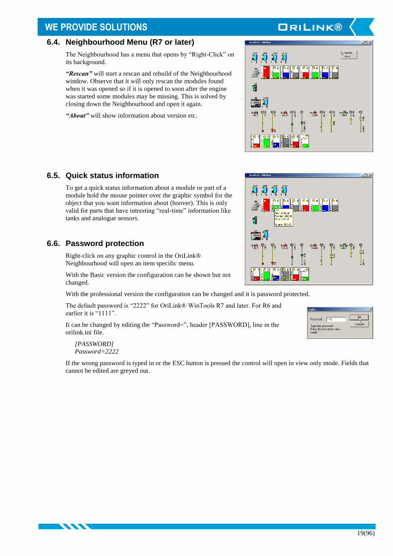
6.4. Neighbourhood Menu (R7 or later)
The Neighbourhood has a menu that opens by “Right-Click” on
its background.
“Rescan” will start a rescan and rebuild of the Neighbourhood
window. Observe that it will only rescan the modules found
when it was opened so if it is opened to soon after the engine
was started some modules may be missing. This is solved by
closing down the Neighbourhood and open it again.
“About” will show information about version etc.
6.5. Quick status information
To get a quick status information about a module or part of a
module hold the mouse pointer over the graphic symbol for the
object that you want information about (hoover). This is only
valid for parts that have intresting “real-time” information like
tanks and analogue sensors.
6.6. Password protection
Right-click on any graphic control in the OriLink®
Neighbourhood will open an item specific menu.
With the Basic version the configuration can be shown but not
changed.
With the professional version the configuration can be changed and it is password protected.
The default password is “2222” for OriLink® WinTools R7 and later. For R6 and
earlier it is “1111”.
It can be changed by editing the “Password=”, header [PASSWORD], line in the
orilink.ini file.
[PASSWORD]
Password=2222
If the wrong password is typed in or the ESC button is pressed the control will open in view only mode. Fields that
cannot be edited are greyed out.

20(96)
6.7. MPDM (23 400)
The Port (Reel) is a member of an MPDM. The MPDM is called the host. Each of
the four ports in a MPDM is presented with a reel icon.
Above the icon is the Port number and Address shown and to the lower left the reel
number is shown.
If the little square in the upper left corner is green the reel is available for dispensing. If it is yellow the reel is pre-
opened. If it is red the reel is open.
Between the reel number and the reel there is a coloured square, this has the same colour as the tank it is connected
to.
If there is a flash over the reel it indicates a short circuit or at least more than 1.25A on the valve output.
If there is a small red “L” in the upper right part of the reel the PPU (Calibration) lock jumper has been
removed. If the PPU lock jumper have been removed calibration cannot be changed.
“Right-Click” on the icon will open a menu. This menu is used to configure the
hose reel and the MPDM it is connected to.
If the key switch on the MPDM is turned to the OFF or
Override position keys will show over the reel icon
6.7.1. Optional connector
This is as factory default not equipped with a connector that can be soldered in place and
used for miscellaneous digital I/O. It is divided into two groups RC and RE with three
signals each. The graphics shows the status of each signal. They have no adjustable
properties.
6.7.2. Host Properties
With host properties means properties that are valid for the MPDM rather
than each individual port.
First there is a login window, fill in the password and the press OK button.
SphereNo: Sets to which sphere the MPDM belongs. The sphere
property can be used to limit the use of the MPDM to one
or several keypads that belongs to the same sphere. This
can be used to set the reel numbers of the same oil grade to
the same as in other spheres.
For example
Work bay 1 Work bay 2 Work bay 3
Sphere number 1 2 3
Oil grades Reel number Reel number Reel number
Motor oil 1 1 1
Gearbox oil 2 2 2
Hydraulic oil 3 3 3
Coolant 4 4 4
It is possible to open a dispense point in another sphere by typing “ReelNo.SphereNo” at the Reel: prompt on
a keypad. Reel:2.1<ENTER>will open Reel number 2 in sphere 1.

21(96)
Internal users: This only works if the MPDM is flashed to software
version MPDM10010_IUD.
Then the MPDM has a small local user database that
can store up to 16 users by a four digit PIN code only.
OBSERVE ! When flashed with this software the
MPDM does not support external validation or
sending transaction data to a database.
By “Right-Click” on the
white background a User
Pin can be added.
If Add User is selected an AddNew PIN-code window
appears.
Type a new PIN-code and then Left-Click OK.
By “Right-Click” a User Pin it can be deleted.
Select Delete User and “Left-Click” the OK then the
selected the user is deleted.
PLC Code: In this window PLC code can be added to create advanced functions for the
MPDM, see.Chapter “12. Using the MPDM as a PLC (Programmable Logic
Controller)”.
6.7.3. Port(n) properties.
This choice opens the reel property window. First there is a
login window. If ESC or wrong password is typed the reel
property window opens but only for viewing. See also the
MPDM manual.
ReelNumber: Is the Reel identification number.
Group: Sets to which group(s) the reels belong(s) to.
Mask: Sets the functionality of the dispense point.
Use pulse compensation, Sets whether the automatic
after-run compensation should enabled or
not.
Use PortB as a trigger, Sets if an active low on Port
B should start a dispense of the set “Max
volume” or not.
Use 2-signal meter, Sets whether to detect two pulse trains from the meter or not. If a
meter with two phase separated pulse trains is used this will increase accuracy,
compensate for oscillating flow and detect flow direction.
Dual/Quadra pulse count, Sets whether the both up and down pulse flanks should be
counted or not. Enabling it with only one pulse train set double the PPU and with
2 pulse trains the PPU will be 4 times. This can increase accuracy a lot especially
for meters with low PPU or when dispensing small volumes.
Cyclic dispense mode, Sets whether the dispense point should be used as a lubrication
timer or not. If enabled it dispenses the set “Max volume” every “Timeout” in
minutes. If pulses are not detected within 30 seconds the dispense point shuts
down and set a pin of the optional connector to low. See chapter 13 for details.
Count down, Sets whether the display should count up or down.
Timeout: Specifies the dispense no activity timer.
PPU: Pulses Per Unit, the calibration. If the “PPU Lock” jumper on the board is removed this
field is greyed out and cannot be changed.
22(96)
Min volume: Minimum dispensable volume, use decimal point. (Do not set this lower than
0.050 and “Use pulse compensation” at the same time without proper testing.)
Max volume: Maximum dispensable volume, use decimal point (also used as dispense volume
when “Use PortB as trigger” is enabled).
DB Address: Data base address (2XXX). This is used for external validation. Must be set to
2999 if the reel should use the PC database.
Sec DB Address: Secondary data base address (2XXX). This can be used for a local backup of
transaction in a printer module. If a printer is connected a recite will be printed.
LED Address: Led display address (4XXX).
Decimals: Sets the number of decimals shown on the display specified at LED Address.
Tank No: Which tank the reel is connected to.
Quick Settings: Only R10. These buttons will set the dispense point to some commonly used
generic setting.
When everything is properly set “left-Click” the OK button to save the set-up.
Each port must be configured according to the wanted functionality. The ports can be completely individually
configured.
To the left is a normal configuration for a port that should fully work with the OriLink® PC database.
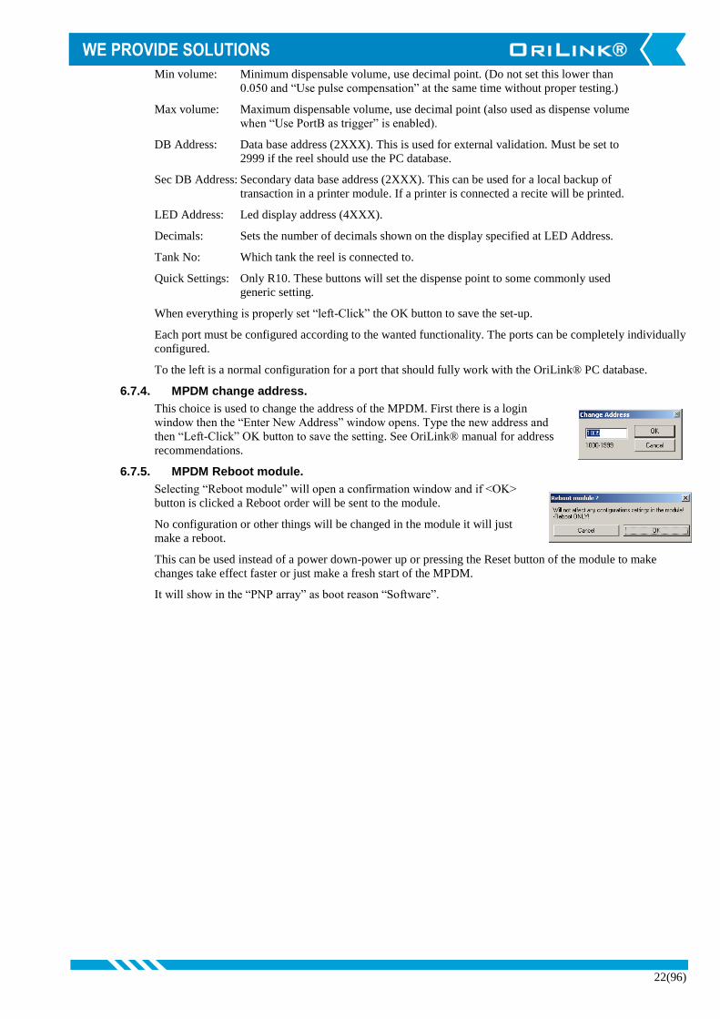
6.7.4. MPDM change address.
This choice is used to change the address of the MPDM. First there is a login
window then the “Enter New Address” window opens. Type the new address and
then “Left-Click” OK button to save the setting. See OriLink® manual for address
recommendations.
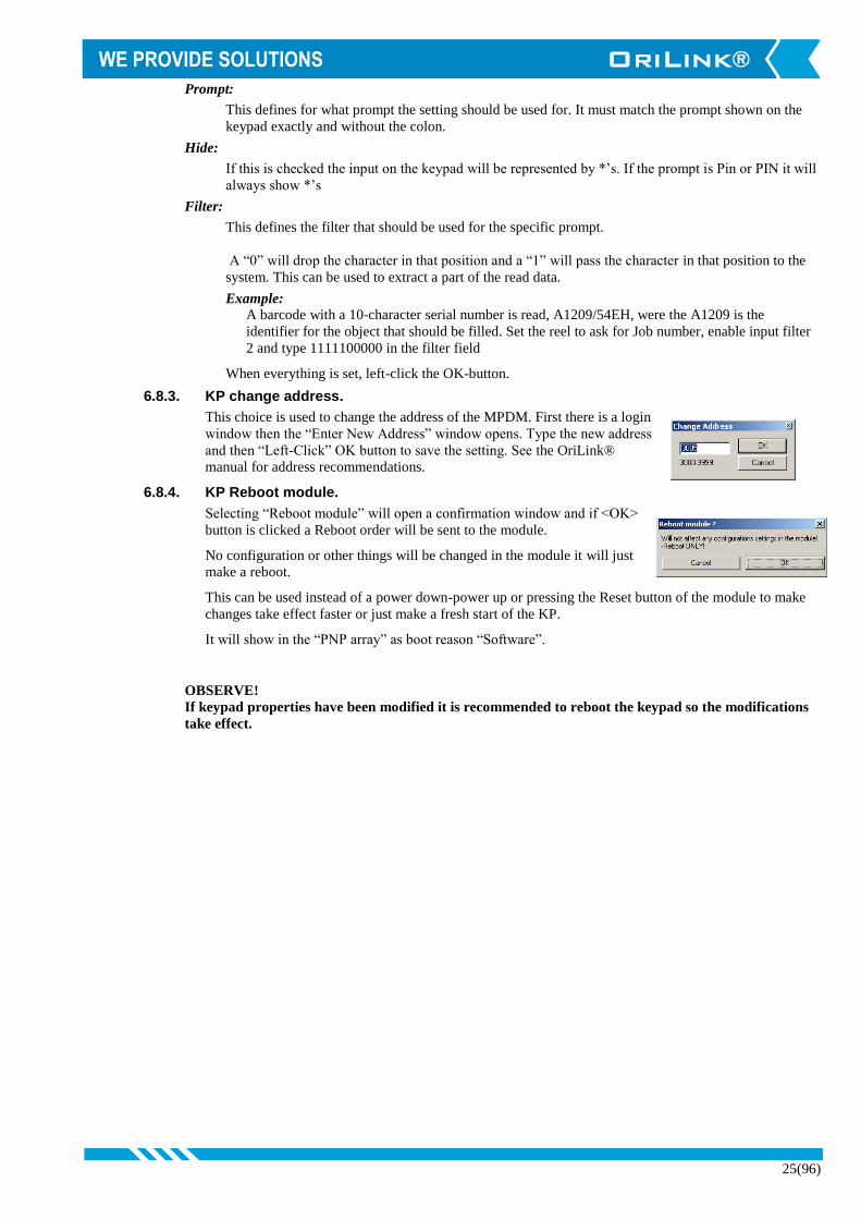
6.7.5. MPDM Reboot module.
Selecting “Reboot module” will open a confirmation window and if <OK>
button is clicked a Reboot order will be sent to the module.
No configuration or other things will be changed in the module it will just
make a reboot.
This can be used instead of a power down-power up or pressing the Reset button of the module to make
changes take effect faster or just make a fresh start of the MPDM.
It will show in the “PNP array” as boot reason “Software”.

23(96)
6.8. KeyPad (23 401)
The address of the KP is shown above the icon. “Right-clicking” the icon open the KP menu.
The KP icon changes the visual appearance according to the status of the physical KP.
The KP icon changes when it is equipped with a serial port interface kit and a chip v1.00.00 or later, the
small triangle on the left side.
6.8.1. Edit Fast Menu
Selecting this opens a window for editing the Fast Menu. The Fast Menu is accessed
by pressing the “?” mark on the KP.
First there is a login window, fill in the password and the press OK button.
Then the KP FastMenu window opens.
In the “Code” column is the address of the target module + the
Fast menu code for item menu wanted.
In the “Info” column is the item text presented in the keypad
fast menu item list.
If the column “PIN” contains a value a PIN request will come
up and the set PIN must be given to get to the menue item.
By “Right-Click” on a code item it could be edited or
removed.
By “Right-Click” in the white area a new item can be added.
Adding a Fast Menu item is done through the Add New Fast
Menu Item window.
To create the Code, see manuals for the specific module.
The Info field will be shown on the KP display.
If a PIN code is added (4 figures) to the fast menu item it must be typed in
from the KP when this item is used
6.8.2. KP properties.
This choice is used to define how the KP should be set-up. First there is a login window, fill in the password
and the press OK button. There are two different possible properties windows, one older and one newer.
Older Newer/R10

24(96)
The KP could be set-up in three different ways,
REEL: This is default normal workshop use.
CODE: This is for special use for example only JOB number input. See manual for the
appropriate module.
Fast Menu: This set the KP for Fast Menu use for example Office or Stock use.
Sphere No This can be set if the keypad is equipped with a FLASH chip and OriLink®
WinTools R7 or later is installed.
If the keypad is equipped with an OTP chip the SphereNo is always “0”.
Timeout: This set the KP session inactivity time-out. It is in seconds and 60 or less is
recommended for general use. Above 60 can be used for example when it is used
for door opening and similar functions. Setting it to 0 disables timeout.
Next part of the KP properties window is the set-up for the optional serial interface.
Baudrate:
Must be set to match the setting of the
reader used. If our Dallas key/iButton
reader kit 23419 is used the option
“DallasKey” should be selected.
If the keypad is based on 2 printed cirquit
boards (older type) only 1200 and 2400
Baud is possible. If something else is
selected it will default to 1200.
If the keypad is based on 1 printed cirquit
board (newer) and the module software is
Kp10010RC1 or later any of the listed
baud rates could be selected. The keypad
will auto detect asynchronous or
synchronous communication.
Up to four different inputs can be
configured. Each has 4 ways of triggering,
ENTER-button on keypad, CR/LF,
Decode and CR/LF or Decode.
CR/LF and Decode unchecked:
Makes it possible for the user to verify the
input by pressing ENTER-button on
Keypad.
Only CR/LF checked:
Results in “auto-ENTER” if the reader
sends CR/LF at the end of the
information. All other inputs must be
verified by pressing ENTER-button on
Keypad.
Only Decode checked:
Results in “auto-ENTER” if the reader sends a “complete decode” signal. All other inputs must be
verified by pressing ENTER-button on Keypad.
Both CR/LF and Decode checked:
Results in “auto-ENTER” if the reader sends CR/LF or a “complete decode” signal. All other inputs
must be verified by pressing ENTER-button on Keypad.
Enable filter:
In addition to this an individual input filter can be enabled.
25(96)
Prompt:
This defines for what prompt the setting should be used for. It must match the prompt shown on the
keypad exactly and without the colon.
Hide:
If this is checked the input on the keypad will be represented by *’s. If the prompt is Pin or PIN it will
always show *’s
Filter:
This defines the filter that should be used for the specific prompt.
A “0” will drop the character in that position and a “1” will pass the character in that position to the
system. This can be used to extract a part of the read data.
Example:
A barcode with a 10-character serial number is read, A1209/54EH, were the A1209 is the
identifier for the object that should be filled. Set the reel to ask for Job number, enable input filter
2 and type 1111100000 in the filter field
When everything is set, left-click the OK-button.
6.8.3. KP change address.
This choice is used to change the address of the MPDM. First there is a login
window then the “Enter New Address” window opens. Type the new address
and then “Left-Click” OK button to save the setting. See the OriLink®
manual for address recommendations.
6.8.4. KP Reboot module.
Selecting “Reboot module” will open a confirmation window and if <OK>
button is clicked a Reboot order will be sent to the module.
No configuration or other things will be changed in the module it will just
make a reboot.
This can be used instead of a power down-power up or pressing the Reset button of the module to make
changes take effect faster or just make a fresh start of the KP.
It will show in the “PNP array” as boot reason “Software”.
OBSERVE!
If keypad properties have been modified it is recommended to reboot the keypad so the modifications
take effect.

26(96)
6.9. Printer Module (23 402)
The Printer Module (PM) contains a printer interface and a database. In this database there are 8 software tanks,
room for 32 users and 900 transactions. A customized receipt layout can be
programmed.
6.9.1. Printer interface and database.
This icon represents the Printer interface and the
database.
Right-click the icon and a menu will be shown.
6.9.1.1. Transactions
If transactions are selected a window for handling the transaction
database appears. It can have either of two layouts.
Older versions Later versions
From this window it is possible to,
Update: Updates the Last Transactions area or fetch all transactions existing, depending
on version, to see if any new transactions have been made.
DeleteAll: Empties the database.
ByTransactionNumber:
Prints a transaction report for an interval of transactions if there is a printer
connected to the module.
ByJobNumber: Prints a transaction report for a job number transaction if there is a printer
connected to the module.
ByEmployeNumber:
Prints a transaction report for an
employee number transactions if there is a
printer connected to the module.
Report period:
Here you select the start and end dates for
the wanted report period. Select the dates
by the date picker and click <Save> when
done. Then print your reports.
27(96)
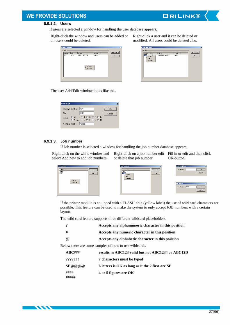
6.9.1.2. Users
If users are selected a window for handling the user database appears.
Right-click the window and users can be added or
all users could be deleted.
Right-click a user and it can be deleted or
modified. All users could be deleted also.
The user Add/Edit window looks like this.
6.9.1.3. Job number
If Job number is selected a window for handling the job number database appears.
Right click on the white window and
select Add new to add job numbers.
Right-click on a job number edit
or delete that job number.
Fill in or edit and then click
OK-button.
If the printer module is equipped with a FLASH chip (yellow label) the use of wild card characters are
possible. This feature can be used to make the system to only accept JOB numbers with a certain
layout.
The wild card feature supports three different wildcard placeholders.
? Accepts any alphanumeric character in this position
# Accepts any numeric character in this position
@ Accepts any alphabetic character in this position
Below there are some samples of how to use wildcards.
ABC### results in ABC123 valid but not ABC1234 or ABC12D
??????? 7 characters must be typed
SE@@@@ 6 letters is OK as long as it the 2 first are SE
#### 4 or 5 figures are OK
#####

28(96)
6.9.1.4. Edit Receipt
If Edit receipt are selected a window for handling the
receipt layout appears.
From this window it is possible to,
Load default: This can be used to reload the default receipt
if something has gone wrong.
Load compact: This can be used to load a more compact
receipt.
Load from file: Can be used to load a custom made receipt
from a text file.
Print Test: Can be used to test the printer.
Report>>>: Can be used to edit the report layout.
Save and Exit: Downloads the receipt to the printer module
and exits.
Exit: Exits without doing anything.
The Receipt window:
Can be used to edit the receipt in the printer module directly. All text and underlining without @-
symbol in front of it can be edited normally. All characters after or between @-symbols must be
edited with knowledge of what they mean. The same goes for the thick vertical line-symbol in front
and end of “receipt title” and “volume: @09”.
The @-symbol is a placeholder for a field value from the database and the two following characters
identify the field.
The thick vertical line-symbol in front and end of is control codes for the printer to start and stop big
character printing. These characters cannot be typed in easily but they can be copied and pasted. The
one in the beginning and the one at the end is not the same.
On the OriLink® WinTools CD in the folder “?:\Extras\Reciept files\PM\” there are some sample
layout text files.
When creating or editing the PM report layout the rules stated in ReadMePM.txt file must be
followed.
The ReadMePM.txt file can be found in the “C:\Orilink\Reciept\PM” folder or on the CD in the folder
“?:\EXTRAS\Reciept Files\PM)”
To restore the default report layout, click the “Load default” button and then the “Save and exit”
button.

29(96)
6.9.1.5. Edit Report
If the Report >>> button is clicked the edit
window for the report is opened.
This window has one white editing area for
each part of the report. The fields placement
holders, beginning with a @ sign is the same
as for receipts.
Click in an area at the desired input place
and edit like with for example notepad.
When you are finished click the Save and
Exit button.
When creating or editing the PM report
layout the rules stated in ReadMePM.txt
file must be followed.
The ReadMePM.txt file can be found in the
“C:\Orilink\Reciept\PM” folder or on the CD
in the folder “?:\EXTRA\Reciept Files\PM)”
To restore the default report layout click, the
“Load default” button and then the “Save
and exit” button.
6.9.2. Tank properties
8 icons like this represent the tanks.
1. Shows fluid name.
2. Shows total tank volume.
3. Shows update timer, double-click and it updates immediately.
4. Shows tank number.
5. Shows stock level.
6. Shows reorder level.
7. Shows Stop level.
If the mouse pointer is held over the icon for a short while the status of the tank will
show.
By “Right-Clicking” a tank icon its
properties can be edited.
When selecting “Properties” a login
window appears. Type the password
and “Left-Click” the OK button.
Now the tank property window appears. If a valid password is typed everything can be edited but if
wrong password is typed or ESC is pressed only the Current Volume can be updated.
6.9.3. PM change address
This choice is used to change the address of the PM. First there is a login
window then the “Enter New Address” window opens. Type the new address
and then “Left-Click” OK button to save the setting. See OriLink® manual for
address recommendations.

30(96)
6.10. Serial interface (23 403)
For now the OriLink® SIO module (Serial In/Out module, PC-Interface) only acts as a router and a communication
line amplifier. It has no address or other configurable parameters and because of this it has no graphic representation
in the OriLink® Neighbourhood.
6.11. LED display (23 404)
A LED graphic icon can have two different looks. It depends on if it is an older LED100 or the
newer LED101 type. LED101 has a PCB version of “203 02 66C” or later. On the LED101 the
built in dispense point controller port can be used as a normal dispense point.
LED101 shows both a LED and a REEL.
LED100 shows only a LED.
The LED icon changes the visual appearance according to the status of the physical display. The
change is a real time status so there will be a difference between the icon and the physical display.
The address of the LED is shown above the icon(s). For a port icon for example Reel the port number is shown
before the address as Port/Address. For a complete status description see 6.7 MPDM (23 400)
“Right-clicking” the LED icon opens the LED menu.
“Right-clicking” the REEL icon (only LED101) opens the
REEL menu.
6.11.1. LED Properties.
This choice is used to define how the LED should be set-up. First there is a login window, fill in the
password and the press OK button.
The LED could be set-up in three different ways,
Visible Time: This sets how long a finished dispense should be shown
before the LED times out to show the time or a “-“ sign, the
value is in seconds. Setting it to “0” means “Do not time-out”.
PPU: This is the calibration for the built in dispense point controller.
For LED101 the PPU: field is greyed out because the PPU is
set from the Reel Properties.
For LED100 all fields are usable.
Clone address: This can be used to clone another display. Let’s say that we have a LED with
address 4005 that shows something we also want to see on this display, then we set
Clone address to 4005 and the output of 4005 will also be seen on this display.
Mask: Disable clock: This sets whether the LED should time-out to showing the clock or a “-“ sign.
Disable update warning: This sets whether the LED should blink to warn for a
missed update or not. Checking this is mostly intended for displays that should show
a tank content from a TCM with analogue sensor.
Disable update time-out: This sets whether the LED should time-out for missed
updates or not. Checking this is mostly intended for displays that should show a tank
content from a TCM with analogue sensor.
6.11.2. LED Change address.
This choice is used to change the address of the LED. First there is a login window
then the “Enter New Address” window opens. Type the new address and then
“Left-Click” OK button to save the setting. See OriLink® manual for address
recommendations.
31(96)
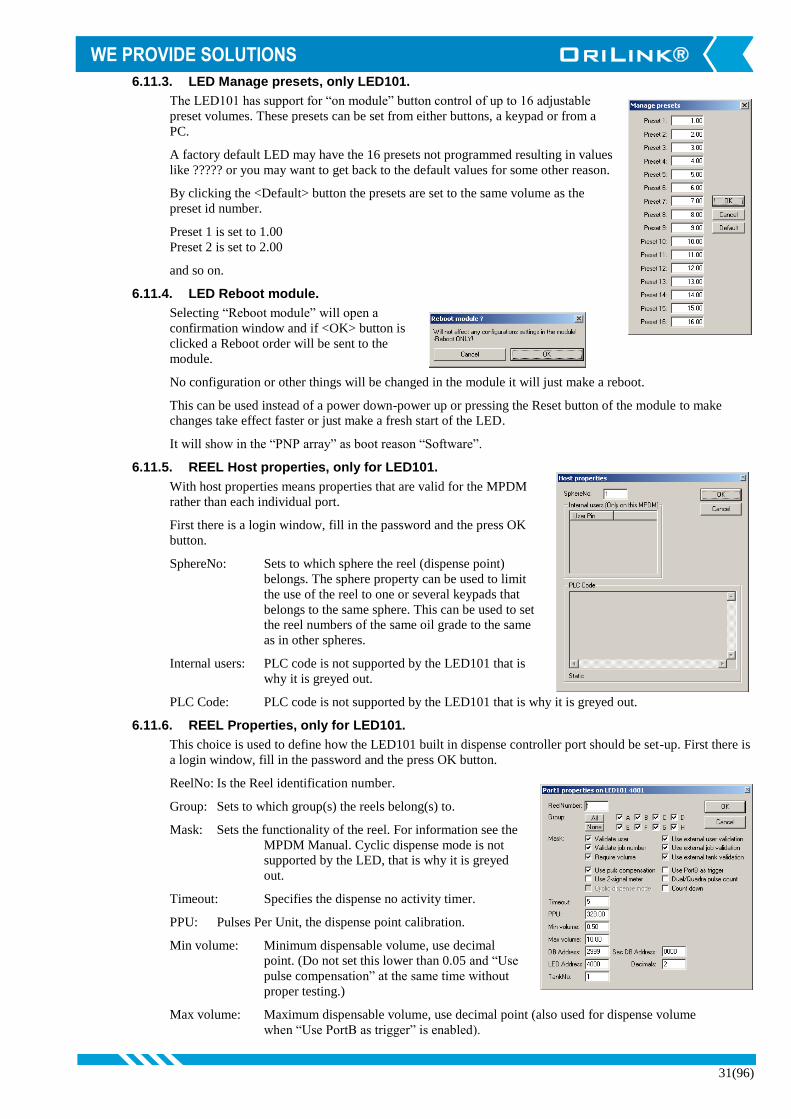
6.11.3. LED Manage presets, only LED101.
The LED101 has support for “on module” button control of up to 16 adjustable
preset volumes. These presets can be set from either buttons, a keypad or from a
PC.
A factory default LED may have the 16 presets not programmed resulting in values
like ????? or you may want to get back to the default values for some other reason.
By clicking the <Default> button the presets are set to the same volume as the
preset id number.
Preset 1 is set to 1.00
Preset 2 is set to 2.00
and so on.
6.11.4. LED Reboot module.
Selecting “Reboot module” will open a
confirmation window and if <OK> button is
clicked a Reboot order will be sent to the
module.
No configuration or other things will be changed in the module it will just make a reboot.
This can be used instead of a power down-power up or pressing the Reset button of the module to make
changes take effect faster or just make a fresh start of the LED.
It will show in the “PNP array” as boot reason “Software”.
6.11.5. REEL Host properties, only for LED101.
With host properties means properties that are valid for the MPDM
rather than each individual port.
First there is a login window, fill in the password and the press OK
button.
SphereNo: Sets to which sphere the reel (dispense point)
belongs. The sphere property can be used to limit
the use of the reel to one or several keypads that
belongs to the same sphere. This can be used to set
the reel numbers of the same oil grade to the same
as in other spheres.
Internal users: PLC code is not supported by the LED101 that is
why it is greyed out.
PLC Code: PLC code is not supported by the LED101 that is why it is greyed out.
6.11.6. REEL Properties, only for LED101.
This choice is used to define how the LED101 built in dispense controller port should be set-up. First there is
a login window, fill in the password and the press OK button.
ReelNo: Is the Reel identification number.
Group: Sets to which group(s) the reels belong(s) to.
Mask: Sets the functionality of the reel. For information see the
MPDM Manual. Cyclic dispense mode is not
supported by the LED, that is why it is greyed
out.
Timeout: Specifies the dispense no activity timer.
PPU: Pulses Per Unit, the dispense point calibration.
Min volume: Minimum dispensable volume, use decimal
point. (Do not set this lower than 0.05 and “Use
pulse compensation” at the same time without
proper testing.)
Max volume: Maximum dispensable volume, use decimal point (also used for dispense volume
when “Use PortB as trigger” is enabled).

32(96)
DB Address: Data base address (2XXX). Must be set to 2999 if the reel should use the PC
database.
Sec DB Address: Secondary data base address (2XXX). This makes it possible to send transaction
records to a secondary database. If it is a Printer module with a printer attached a
receipt will be printed.
LED Address: Led display address (4XXX). This field has no effect for a LED101, it will
always use its own address.
Decimals: Sets the number of decimals shown on the display specified at LED Address.
Count down: Sets whether the display should count up or down.
TankNo: Which tank the reel is connected to.
When everything is properly set “left-Click” OK button to save the set-up.
6.12. Clock module (23 405)
The OriLink® CM module (Clock Module) has no graphic control or graphic representation of its own in the
OriLink® Neighbourhood.
In the Engine menu “Update PNP Modules” all modules with a CM will have the “R” flag set.
If there is a CM installed in the system (on LED or PM) it will be automatically detected and will supply the date
and time to all modules that needs it.
The date and time for a CM can be set from a Keypad or by using the software Olset.exe found in the C:Orilink
folder.
Observe ! - There can only be one date and time source in a system.
See also chapter “7.1 Time synchronisation”

33(96)
6.13. Tank control module (23 408)
The graphic control for a TCM (Tank Control Module) is divided in three objects for each
port, one solenoid valve one discrete level sensor symbol and one analogue level sensor
symbol.
The symbols change their graphical appearances according to the physical status and the system set-
up.
A TCM has 4 ports which results in that the graphic representation will be 4 groups of valve and level
sensor symbols.
6.13.1. Valve symbol
The valve symbol shows if the valve is closed , open or keyed .
OBSERVE! In later versions the coloring of open and closed has been switched to comply with international
standards as shown above.
6.13.2. Discrete level sensor symbol
The discrete level sensor symbol shows both the tank type and the status of the tank.
Normal Reorder Stop
Fresh Waste Fresh Waste Fresh Waste
6.13.3. Analogue level sensor symbol
The analogue sensor symbol shows graphically in real-time the current volume of the tank.
Normal Reorder Stop
Fresh Waste Fresh Waste Fresh Waste
6.13.4. TCM Setup menu
To set-up a TCM port right click either on the valve, discrete sensor
or the analogue sensor symbol to open the menu. It does not matter
which you use because they are the same.
Then left click on the menu item you want to change. Then there is a
login window, fill in the password and the press OK button. If the
password is correct the menu item you selected will open.

34(96)
6.13.4.1. Host properties
In the host properties you can add PLC code that can be used to
control inputs and outputs in various logic ways. See chapter
12.
OBSERVE ! If you intend to control the pump (Sol-pin of the 5-pole
connector) by PLC code, remember to uncheck “Enable
automatic pump control (Sol)” for the port in question.
6.13.5. Port[n] properties
TankNo: Is only used by the system to
disable not used analogue sensor
inputs from giving an alert.
Setting it to 0 disables the alert.
But is good practice to fill in
properly as information.
Waste oil: Leave it unchecked for a fresh oil
tank and check it for a waste oil
tank.
MaxVolume: This value is needed to give a
correct % statement for the quick
status window in graphic layouts
and get the correct colouring of
the analogue sensor.
Reorder Volume: This value is needed to give a
correct % statement for the quick
status window in graphic layouts
and get the correct colouring of
the analogue sensor..
Stop Volume: This value is needed to give a
correct % statement for the quick
status window in graphic layouts
and get the correct colouring of
the analogue sensor.. That makes
support much easier.
Geometry: Here the shape of the tank is
specified.
TankArea(m^2):This is used for tanks with the
same projected area from the
bottom to the top. The area
should be given in m^2 if the
meter range is in bar and density
in kg/dm^3. It is set to 0 if a tank profile file is uploaded.
Load file (.tnk): This is used if a not uniformed tank is used. A tank profile file (.tnk) is a ascii
text file containing 1000 volume values (one on each line) starting a 0 and
increasing in volume steps up to the volume of the tank. After that the tank
volume is reached the tank volume is written on each step. The step values must
include the meter range and the density of the fluid. The density parameter under
group Fluid should always be 1 if a tank profile file is used.
Fluid Name: This value is not necessary but should be set to the same value as in WinDB
Manager. That makes support much easier.
Fluid Part No: This value is not necessary but should be set to the same value as in WinDB
Manager.

35(96)
Density: Sets the density of the fluid that is in the tank at the normal temperature. It is
1,000 for water at 20°C. A good estimation for mineral oil is 0,875 at 20°C.
Pump control: This should normally be checked but if the pump control of a port is controlled
by PLC code or script it should be unchecked to not cause a conflict.
Discrete sensor: This setting defines how signals to the A and B inputs should be interpreted. To
get highest security they should be checked and normally open sensor should be
used. The reason for this is that the pump will stop if the sensor is disconnected
then.
Analogue sensor: Here the parameters for an analogue industrial 2-lead 4-20mA sensor is set.
Time(t): Sets the time constant for the reaction of a step change of the volume. A low
value will result in faster update but a more turbulent value. Higher value will
give a slower update but a more stable value. Default is “6” which will give
about 30 s to “full update”.
Zero Offset: This value is used to set the level reading to zero when when the tank is empty.
If the 0.5bar level sensor 23417 is used a common value is “–0.075”. The best
and fastest way to set this is to use a keypad and fast menu code, see TCM
manual.
Span Gain: This value can be used to fine tune the amplification between sensor and TCM
input, that is adjusting so that the reading is 20mA at the full meter range. If the
0.5bar level sensor 23417 is used a common value is “1.017”.
Meter Range: This value specifies the measuring range for the used level sensor. If a 23417
level sensor is used it should be set to 0.500. If a sensor with a maximum
pressure of 0.1 bar is used it should be set to 0.100.
LED Address: This is set when a LED display should be used for remote reading of the tank
level.
OBSERVE! If this is set, that LED will be unavailable for showing dispensing.
Update interval: If a LED is set to show the tank volume this can be used to slow down the
updating. The default is once every second and that is not needed and can cause
unnessecary net load in big systems or system with many tanks. The default
value is 1 and a setting of 5-10 will significantly reduce net load.
NOTE ! – DO NOT SET IT TO 0
NOTE ! - If this is set to something higher than 2 you must also set the LED to
accept longer update interval otherwise it will blink to alert of missing updates
and at above 5 it will time out to it’s default screen, time or -.
Disable AAW: This can be used to disable analogue level sensor alert for TCM ports that are not
in use.
6.13.6. Change address
This choice is used to change the address of the TCM. First there is a
login window then the “Enter New Address” window opens. Type
the new address and then “Left-Click” OK button to save the setting.
See OriLink® TCM manual for address recommendations.
6.13.7. Reboot
Selecting “Reboot module” will open a confirmation window and if <OK>
button is clicked a Reboot order will be sent to the module.
No configuration or other things will be changed in the module it will just
make a reboot.
This can be used instead of a power down-power up or pressing the Reset button of the module to make
changes take effect faster or just make a fresh start of the LED.
It will be show in the “PNP array” as boot reason “Software”.

36(96)
7. Loading OriLink® Services
In an OriLink® PC based system it is possible to load system functions called Services. Some services are installed as
standard when OriLink® WinTools is installed but to enable them they have licensed and to be loaded.
A service is loaded by selecting properties from the Engine Menu.
Left-Click the “Engine” window and select
“Properties”.
Right-Click the “Loaded Services” window and
select “New Service”.
Standard services installed by the installation of OriLink® WinTools are Clock Service (Clock.dll), WinDB Service
(WinDB.dll), Script Service (Script.dll), Messaging Service (Messagin.dll and DBDock Service (DBDockS.dll).
7.1. Time synchronisation (clock.dll Basic and Professional)
If it is desired to use the PC clock as master clock in the OriLink® system, the service clock.dll should be loaded.
The Clock service does not need licenseing.
Before loading it all clock modules (CM part number 23 405) must be removed from Printer and LED modules. If a
LED module has a clock chip/module this is shown by that the (:) between hours and minutes is flashing. If the LED
has a soldered clock chip (Dallas DS1603) disable it by unsolder it or cut the four copper traces on the PCB.
NOTE! There can be only one clock source in the system!
If the PC running OriLink® WinTools is connected to a network and it synchronises time to the network the
OriLink® system will also be time synchronised to the network.
7.1.1. Loading the Clock Service
Left-Click the “Engine” window and select
“Properties”.
Right-Click the “Loaded Services” window and
select “Add new Service”.
Select a Service dll and Left- Click Open-button. The result will be something like this. Left-Click
the OK-button.

37(96)
Shut down and then restart the engine.
Check the Engine.log file to verify that the Clock Service is started properly.
7.2. PC as database (WinDB.dll only Professional)
By loading the service WinDB.dll a Microsoft Access database on the PC can be used instead of the database in a
Printer module. If a database on a PC is used the number of users, fluid grades, stored transactions, etc is almost
infinite (size of hard disk and limitations of MS ACCESS is the limit). It also gives the possibility to have multiple
printouts with different layouts on the same or multiple printers.
The WinDB service is also needed for connections to customer mainframe systems and script handling.
The OriLink® WinTools software must be professional version to be able to use WinDB service.
7.2.1. Loading WinDB service
Right-Click the engine window and select properties.
Left-Click the “Engine” window and select
“Properties”.
Right-Click the “Loaded Services” window and
select “Add new Service”.
Select WinDB.dll and Left- Click Open-button. The result will be something like this. Left-click
the OK-button.
Shut down and then restart the engine.
Check the Engine.log and WinDB.log files to verify that the service is started properly.

38(96)
7.2.2. Set-up a dispense point to use PC database
Open the OriLink® Neighbourhood and
“Right-Click” the desired reel icon and
select properties.
First there is a login window, fill in the
password and the press OK button.
Select the things you want to validate external. Right column
of Mask check boxes
Then set DB Address to 2999. The address of the PC database
is hard coded to 2999.
“Left-Click” the OK button to save the changes. Repeat this
for all reels that should use the PC as database.
7.3. Script Service (Script.dll only Professional) part number 23475
The Script service has to be licensed and can be used for total
customisation of the dispense logistics and to do that it has to be
combined with a script set placed in the C:\Orilink\CSL folder. The script
set files have the extension .csl. This is how it looks when Script service is
loaded.
See the Script service manual
7.4. Messaging service (Messagin.dll only Professional) part number 23481
The Messaging service has to be licensed and can be used to send tank
status information in several ways.
This is how it looks when the Messaging service is loaded.
When you first load the service it shows it’s
information window that looks like this.
The information window shows messaging
activities. It does not need to be show for the
service to work so it can be closed.
See the Messaging service manual for detailed information.

39(96)
7.5. DbDocking Service (DbDockS.dll only Professional) part number 23477
In OriLink® WinTools R6 or later there is a new loadable Service called DBDockS included.
This service can be used to automatically detect connected printer modules and download all transactions that have
not been downloaded before.
When the service downloads transactions it inserts them into the standard OriLink® access database.
Then these transactions can be used in WinDB Manager standard reports or handled through MSExcel, MSAccess
or any other ODBC compatible spreadsheet program.
It is recommended to set up the printer module tanks according to created PC database tanks before making
dispenses that are stored in the printer module.
To be able to load the service there must be a License.dat file that is validated for this service.
To load the DBDockS Service
Right-Click the engine window. Then select properties, Add new service.
Select the DBDockS.dll file and left-click the
Open-button.
Left-Click the OK-button.
Shut down and then restart the engine.
Check the Engine.log and DBDockS.log files to verify that the service is started properly.

40(96)
8. Using the WinDB Manager software.
The OriLink® WinDB Manager is a software tool for administration of the OriLink® PC database.
OriLink® WinDB manager is dependant of that MDAC or later and MSJET are properly installed on the PC and that
the ODBC key “OriLinkWinDB” is properly set.
8.1. OBSERVE !
The language in WinDb Manager is controlled by the language file C:\Orilink\Lang.lan. Id can easily be modified
to support different languages like,
Languages for countries
Languages for parts of a country
Special languages for a specific system
The OriLink® has several tables and columns in each table and they all have names associated with specific
parameters needed for fluid filling systems.
But to make a system for a specific need both the language file and the use of the database can be altered.
If it has been altered this manual may not match your system in details but the structure is still valid.
8.2. Start
Click Start button (lower left corner of screen)
Choose Programs
Choose OriLink
Click OriLinkWinDB Manager
A login window will appear. The user will show the currently logged in user. Type the password 1111 (Default) and
click “OK” button. The WinDB Manager starts.
The program follows a standard windows application.
All task windows contain a <REFRESH> button. This button is used to update the window with the current values
in the database. This is needed because the database is multi user and can be altered by a dispense or some other
OriLink® activity.
8.3. Changing user password
Editing the [DBManager] section of the orilink.ini file can change some basic things. This section looks like this.
[DBManager]
AllowSizing=0
Password=1111
ManagePassword=44232413
OBSERVE! The ManagePassword cannot be edited since is encrypted. This must be changed from within
WinDb Manager. If it has been forgotten, see chapter “8.3.3 Changing Management password”,
below.
8.3.1. Chose if the main window should be sizable or not
Edit the AllowSizing= line.
AllowSizing=0
The install default, will prevent the main window from maximizing (Windows 8 and 10) and from manual
resizing.
AllowSizing=1
Will allow resizing of the main window.
OBSERVE ! WinDb Manager is a multi doc application so sub windows are not linked to the main window.
This means that there is no need to have a big main window or even have it open at all.

41(96)
8.3.2. Changing user password
Edit the Password= line.
Password=2323
Will give the password 2323
8.3.3. Changing management password
ManagePassword= string defines the management
password for the management menu.
This is encrypted so it can only be set or modified from
the management menu item “Administrator”.
When clicked the password change form comes up. Type in the desired
password and then press <OK> to save it.
If you have forgotten your password just erase the whole “ManagePassword= “ and then login without
password. Then you can set a new password.
8.3.4. How to disable the login form.
With a empty password “Password=” line and with the “ManagePassword= “ line erased the login form will not
be shown.

42(96)
8.4. View Menu
In the view menu there are two ways to view stored dispenses. It is only possible to view the transactions not edit or
delete them.
8.4.1. Transaction and Transaction table
This gives the possibility to view all information stored for a single transaction. The transactions are shown
in the order “latest first”.
Transaction table shows parameters that are generally most interesting.
Transaction shows all parameters stored for a transaction.
Stop code
Shows how the dispense was stopped.
0 = Requested volume is reached
1 = Manual stop from Keypad, Neighbourhood or Script
2 = Time-Out
3 = Short circuit
4 = By p4b, for example stop button
5 = Requested volume is 0 or negative
Over run
Shows how many pulses counted after that the stop order has been given.
Generally the “Over run” is,
Low for low viscous fluids, low flow rates and fast direct operated valves.
High for high viscous fluids, high flow rates and slower pilot operated valves.
If the parameter “Use pulse compensation” is checked for a dispense point, the dispense point continuously
tries to adapt to the dispense scenario to minimize the “over run”.
If one or some dispense points for the same fluid has much higher “Over run” than the others it can depend
on some dirt in the valve, air in the pipes or dirt in the meter.
8.4.2. Operator details
Show all parameters except the PIN for the
current operators. The operators are shown in
alphabetic order.

43(96)
8.4.3. Tank Stock update history
Shows manually added or removed volumes by the Management-Tanks menu or by tank graphics in
Neighbourhood or a layout.
OBSERVE ! Tank content changes by an analogue sensor cannot be recorded so it is not shown here.
8.4.4. Tank Message history
Show the history of tank status messages sent by the OriLink® Messaging Service.
8.4.5. Db Docking Service transaction table
Shows transactions downloaded from a Printer
module by the OriLink® Db Docking Service. It
can be used to see from which printer module it
comes and what the original printer module
transactions number it has.
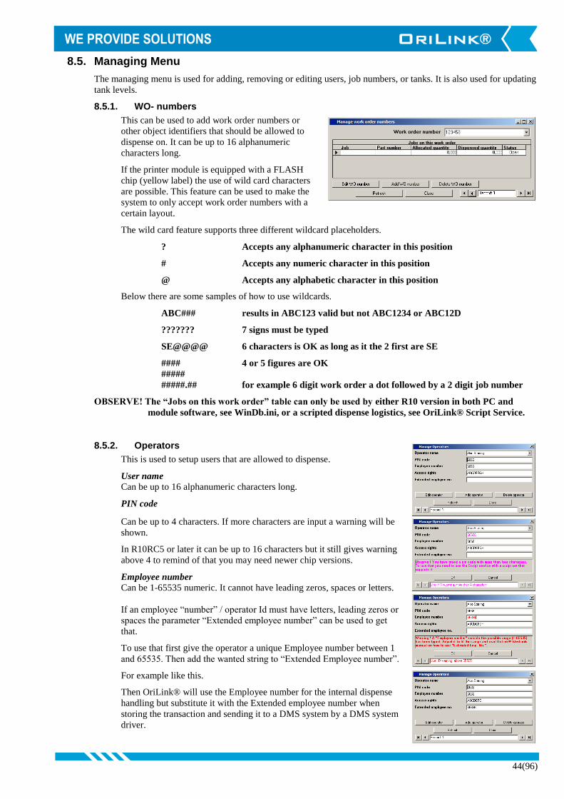
44(96)
8.5. Managing Menu
The managing menu is used for adding, removing or editing users, job numbers, or tanks. It is also used for updating
tank levels.
8.5.1. WO- numbers
This can be used to add work order numbers or
other object identifiers that should be allowed to
dispense on. It can be up to 16 alphanumeric
characters long.
If the printer module is equipped with a FLASH
chip (yellow label) the use of wild card characters
are possible. This feature can be used to make the
system to only accept work order numbers with a
certain layout.
The wild card feature supports three different wildcard placeholders.
? Accepts any alphanumeric character in this position
# Accepts any numeric character in this position
@ Accepts any alphabetic character in this position
Below there are some samples of how to use wildcards.
ABC### results in ABC123 valid but not ABC1234 or ABC12D
??????? 7 signs must be typed
SE@@@@ 6 characters is OK as long as it the 2 first are SE
#### 4 or 5 figures are OK
#####
#####.## for example 6 digit work order a dot followed by a 2 digit job number
OBSERVE! The “Jobs on this work order” table can only be used by either R10 version in both PC and
module software, see WinDb.ini, or a scripted dispense logistics, see OriLink® Script Service.
8.5.2. Operators
This is used to setup users that are allowed to dispense.
User name Can be up to 16 alphanumeric characters long.
PIN code
Can be up to 4 characters. If more characters are input a warning will be
shown.
In R10RC5 or later it can be up to 16 characters but it still gives warning
above 4 to remind of that you may need newer chip versions.
Employee number
Can be 1-65535 numeric. It cannot have leading zeros, spaces or letters.
If an employee “number” / operator Id must have letters, leading zeros or
spaces the parameter “Extended employee number” can be used to get
that.
To use that first give the operator a unique Employee number between 1
and 65535. Then add the wanted string to “Extended Employee number”.
For example like this.
Then OriLink® will use the Employee number for the internal dispense
handling but substitute it with the Extended employee number when
storing the transaction and sending it to a DMS system by a DMS system
driver.

45(96)
Rights
Can be used to divide users and dispense points into groups. Any combinations of A, B, C, D, E, F, G and H
can be used such as AB, ACH, DG and so on.
It is used in combination with the dispense point property “Group”
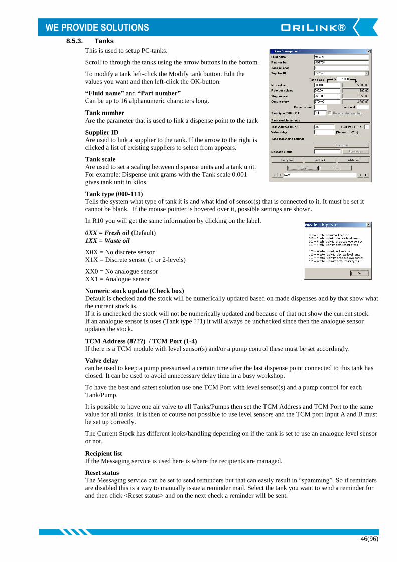
46(96)
8.5.3. Tanks
This is used to setup PC-tanks.
Scroll to through the tanks using the arrow buttons in the bottom.
To modify a tank left-click the Modify tank button. Edit the
values you want and then left-click the OK-button.
“Fluid name” and “Part number”
Can be up to 16 alphanumeric characters long.
Tank number
Are the parameter that is used to link a dispense point to the tank
Supplier ID
Are used to link a supplier to the tank. If the arrow to the right is
clicked a list of existing suppliers to select from appears.
Tank scale Are used to set a scaling between dispense units and a tank unit.
For example: Dispense unit grams with the Tank scale 0.001
gives tank unit in kilos.
Tank type (000-111) Tells the system what type of tank it is and what kind of sensor(s) that is connected to it. It must be set it
cannot be blank. If the mouse pointer is hovered over it, possible settings are shown.
In R10 you will get the same information by clicking on the label.
0XX = Fresh oil (Default)
1XX = Waste oil
X0X = No discrete sensor
X1X = Discrete sensor (1 or 2-levels)
XX0 = No analogue sensor
XX1 = Analogue sensor
Numeric stock update (Check box)
Default is checked and the stock will be numerically updated based on made dispenses and by that show what
the current stock is.
If it is unchecked the stock will not be numerically updated and because of that not show the current stock.
If an analogue sensor is uses (Tank type ??1) it will always be unchecked since then the analogue sensor
updates the stock.
TCM Address (8???) / TCM Port (1-4) If there is a TCM module with level sensor(s) and/or a pump control these must be set accordingly.
Valve delay can be used to keep a pump pressurised a certain time after the last dispense point connected to this tank has
closed. It can be used to avoid unnecessary delay time in a busy workshop.
To have the best and safest solution use one TCM Port with level sensor(s) and a pump control for each
Tank/Pump.
It is possible to have one air valve to all Tanks/Pumps then set the TCM Address and TCM Port to the same
value for all tanks. It is then of course not possible to use level sensors and the TCM port Input A and B must
be set up correctly.
The Current Stock has different looks/handling depending on if the tank is set to use an analogue level sensor
or not.
Recipient list
If the Messaging service is used here is where the recipients are managed.
Reset status
The Messaging service can be set to send reminders but that can easily result in “spamming”. So if reminders
are disabled this is a way to manually issue a reminder mail. Select the tank you want to send a reminder for
and then click <Reset status> and on the next check a reminder will be sent.

47(96)
Without an analogue level sensor.
The current stock can be updated in two different ways.
Left-click in the white value box and just edit it or by left-click the
“Update Stock” button.
When the “Update Stock” button is left-clicked a new form is
shown.
Fill in the volume change and the form automatically adds it to the current
stock.
Use a - sign to reduce the current stock. Left-click the OK-button to
update the database.
If a Volume change is so large that the sum will be over the set tank size a
warning message will appear and the new stock will be set to the size of
the tank.
This can be used as a way to quickly set the new stock when replacing a
barrel or IPC container.
With an analogue level sensor.
If there is an analogue level sensor the current stock is
automatically updated by this sensor. Because of this the
possibility to manually edit the current stock is disabled and there
is no “Update Stock” button.
Observe! If an analogue level sensor is used the “Tank type” value
should be set to XX1.

48(96)
8.5.4. Printing
Here receipts can a printing template be selected and directed to 1 or more printers (print modules). The
receipts can also have different layouts depending of dispense point and/or printer.
First copy and rename a suitable receipt layout file in C:\Orilink\Reciept\PC. Then edit it to how you
want it to look like, see ReadMePC.txt.
Remember that different printer may need different control characters to create effects like thick
characters, different fonts, loading stored pictures, generate barcodes,......, etc. Exactly what is set in the
layout will be sent to the printer.
Print ID
This parameter is auto generated to give a unique ID for each print and cannot be edited. This makes it
possible to have multiple print outs for the same dispense point to the same or different printer(s) and
with the same or different layouts.
Open the Printing utility and Click the <Add>
button, or the <Edit> button if you want to edit a
present print out.
Fill in the information and click on <Update>
button. Do the same for all desired dispense
points. Here to a Printer module with address
2003.
Here to a printer on the local PC using the
Windows printing queue.
To a print queue on a print server in the network.
To a local parallell or serial port:.
If a printer connected a local LPT or COM port is going to be used it must be PCL compatible or similar it
cannot be a GDI printer (Windows printer).
If it is a GDI or USB printer the local windows printing queue for the printer must be used and the “Windows
Printing” must be checked

49(96)
8.5.5. Preset Codes
To use this the OriLink® Script service (p/n
23475)must be used. When OriLink® is
installed a general preset script set is installed
and this uses the settings done here. The
script files can be found in the
C:\Orilink\CSL folder and the configuration
file for it is C:\Orilink\Presets.ini
Basically it is used to start one or more
dispense points by a single input code either
manually or by some reader but it can be used for much more advanced things if needed.
Important to think of is that there must be an unique value for each row otherwise the system cannot
separate them.
If either <Edit Code> or <Add Code> is
pressed the form will change to modification
mode.
And as in any other database tool you have to
click on another row than the one you are
editing/adding to save what you have done.
Function is used to tell the system what
verification(s) you want and by clicking the
“Function” header you will see a list of
possible settings.
By typing the first letter(s) of a Preset code it
is searched and quickly found.
8.5.6. Suppliers
Supplier database can be used for adding a
supplier to a tank. First add the supplier and
give it some unique Supplier ID if they not
already have one.
Then select it from the Supplier list in tank
configuration, see “7.5.3 Tanks”

50(96)
8.5.7. Administrator
Here a Management/Administration password can be
added, replaced or removed.
This password is encrypted so save it somewhere safe
so it can be found if it is forgotten.
It is not possible to retrieve it but it can be reset to “no
password”
8.6. Report Menu
The report menu of WinDB Manager has several sub menus and in each
of them there is reports or sub menus.
For some of the reports one or more input window will appear.
8.6.1. Input WO-number example.
Wildcards could be used when typing a WO-number.
The wildcard sign % can be used as follows,
203164% will give a report for all WO’s that begins with 203164.
%32% will give a report for all WO’s that contains 32
8.6.2. Input dates example
Date it should be typed in the format YYYY-MM-DD for example
2003-02-29. For the “Start time” input the software assumes time to
be 00.00.00 and for the “End time” input it assumes 23.59.59.
The default report period is the last 7 days, 00:00:00 day one to
23:59:59 day seven.
If the same date is typed for both values the report will cover that
date.
The dates can also be changed by Left-Click on the
“drop-down” button to the right of the date. Then a
calendar will appear.
8.6.3. System reports
Here general reports over the system can be found.
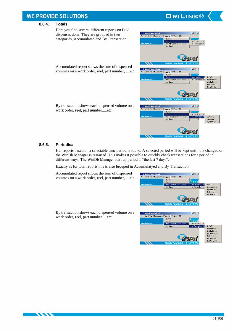
51(96)
8.6.4. Totals
Here you find several different reports on fluid
dispenses done. They are grouped in two
categories, Accumulated and By Transaction.
Accumulated report shows the sum of dispensed
volumes on a work order, reel, part number, ....etc.
By transaction shows each dispensed volume on a
work order, reel, part number.....etc.
8.6.5. Periodical
Her reports based on a selectable time period is found. A selected period will be kept until it is changed or
the WinDb Manager is restarted. This makes it possible to quickly check transactions for a period in
different ways. The WinDb Manager start up period is “the last 7 days”.
Exactly as for total reports this is also brouped in Accumulatyed and By Transaction
Accumulated report shows the sum of dispensed
volumes on a work order, reel, part number, ....etc.
By transaction shows each dispensed volume on a
work order, reel, part number.....etc.

52(96)
8.6.6. Combined
Here reports based on a combinations of selectable parameters is found. A selected period will be kept
until it is changed or the WinDb Manager is restarted.
The WinDb Manager start up period is “the last 7 days”.
Exactly as for total and periodic reports this is also grouped in Accumulated and By Transaction reports.
Accumulated report shows the sum of
dispensed volumes on a work order,
reel, part number, ....etc.
The “By WOs where filled sum is over
limit” and “By WOs where frequency
is over the limit” can be used for
leakage or over consumption control
By transaction shows each dispensed
volume on a work order, reel, part
number.....etc.
The “By WOs with dispenses over the
limit” can be used for leakage or over
consumption control
8.7. Window Menu
The windows menu can be used to arrange the different utilities windows. Not in use in this version.
8.8. Help Menu
In this menu an online manual will be placed. In this release it is not implemented.
8.9. Close the program
The program is closed as normal Windows software. Through the Archive menu or the cross in the upper right
corner.

53(96)
9. HWFlash tool (HWFlash.exe)
The hardware flash tool (HWFlash.exe) replaces all other previous tools for programming and resetting the hardware
modules.
The HWFlash tool can be found in the OriLink® main folder, default is C:\Orilink. It is started by double clicking the
HWFlash.exe file. It supports all types of modules with OTP or Flash chips.
9.1. How to change the system language (R7 or later)
First start the OriLink® engine if it is not already
running. Then start the HWFlash tool. The default
language for booth OriLink® WinTools and
modules is English.
To change it select the new language from the
language selector in the lower left corner of the
HWFlash main window.
Click OK button to accept the language change.
Then click the Rescan button.
Now click the Flash button, The High speed
check box can be checked if there are only flash
modules in the system. Then click the OK button
to accept to flash the modules.

54(96)
The flash procedure starts. Modules marked with
yellow is going to be flashed, module marked with
red is flashed and modules marked with green have
been flashed.
When all modules are marked green the flashing
process is finished.
Now first do a Rescan from the engine menu
“UpdatePNP array” item. Then click the Rescan
button in HWFlash window.
Now the system language is Swedish.
Observe ! The language changing currently only supports hardware modules, the engine and WinDB
Manager. It does not support the graphic representation of the modules in the OriLink®
Neighbourhood (HWMon2).

55(96)
9.2. How to update chip software and/or language for modules.
When the HWFlash tool is started the first thing that happens is that it looks in C:\Orilink\Chip folder and compare
the chip software file versions there with the
current ones in the hardware modules. If there are
newer ones in the chip folder it automatically list
suggested updates in the HWFlash start-up
window.
The second thing that happens is that it compares
the language setting of the system with the one of
the current hardware modules. If any of the
modules has another current language than the
system it is shown as a suggested update in the
HWFlash start-up window.
It can look something like this.
To make the suggested updates click the Flash
button. The High speed check box can be checked
if there are only flash modules in the system.
Then click the OK button to accept.
To skip a suggested language update select the
empty line in the “New language” selector.
To skip a suggested chip software update select the
empty line in the “New version” selector.
To down flash a module to an earlier software version
select it from the “New version” selector.
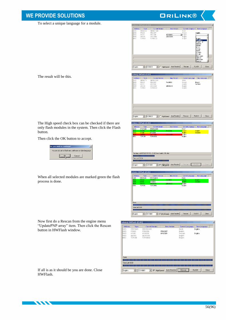
56(96)
To select a unique language for a module.
The result will be this.
The High speed check box can be checked if there are
only flash modules in the system. Then click the Flash
button.
Then click the OK button to accept.
When all selected modules are marked green the flash
process is done.
Now first do a Rescan from the engine menu
“UpdatePNP array” item. Then click the Rescan
button in HWFlash window.
If all is as it should be you are done. Close
HWFlash.

57(96)
9.3. How to change a flash chip from module type to CO type.
Since all modules uses the same processor flash chip it can be moved from one module type to another but to do that
it must either contain software for the target module or just communication (CO chip).
All chip our part number 23482 has CO software so they can directly be inserted in a module and then flashed to the
correct software.
If you want to move the processor chip from one type of module to another type you must first convert it to CO
type. You do this by re-flashing it to the same as it already is and disconnect the flashed module during flash stage 3
“downloading software”. Like this
Select the same software
Start flashing.
Stage 1, flashing the latest CO
software
Reboot to CO Stage 2, the boot vector is
changed to the CO software
and the module is then
rebooted as CO.
CO software is used to receive
the module software selected.
Stage 3, flashing the selected
module software to the
module.
Disconnect the module
The module stops answering
and after some retries
HwFlash prompts for the
issue and ask you to retry or
cancel. Choose Cancel.
Since the flashing process was cancelled before
stage 4 was done the boot vecytor is still pointing
to the CO software.
Connect module and press
Rescan
Now you have a CO chip that
can be moved to other module
types or be flashed to for
example TCM100, PLC100 or
PLC200 softwares.
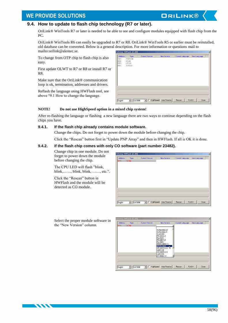
58(96)
9.4. How to update to flash chip technology (R7 or later).
OriLink® WinTools R7 or later is needed to be able to see and configure modules equipped with flash chip from the
PC.
OriLink® WinTools R6 can easily be upgraded to R7 or R8. OriLink® WinTools R5 or earlier must be reinstalled,
old database can be converted. Below is a general description. For more information or questions mail to
mailto:[email protected].
To change from OTP chip to flash chip is also
easy.
First update OLWT to R7 or R8 or install R7 or
R8.
Make sure that the OriLink® communication
loop is ok, termination, addresses and drivers.
Reflash the language using HWFlash tool, see
above “9.1 How to change the language.
NOTE! Do not use HighSpeed option in a mixed chip system!
After re-flashing the language or flashing a new language there are two ways to continue depending on the flash
chips you have.
9.4.1. If the flash chip already contains module software.
Change the chips. Do not forget to power down the module before changing the chip.
Click the “Rescan” button first in “Update PNP Array” and then in HWFlash. If all is OK it is done.
9.4.2. If the flash chip comes with only CO software (part number 23482).
Change chip in one module. Do not
forget to power down the module
before changing the chip.
The CPU LED will flash ”blink,
blink,……, blink, blink, ……, etc.”.
Click the “Rescan” button in
HWFlash and the module will be
detected as CO module.
Select the proper module software in
the “New Version” column.

59(96)
Verify that the correct software is
selected.
Then flash.
After the line has turned GREEN click
the “Rescan” button.
Now all modules should be visible
again.
Change chip in the next module. Click
the “Rescan” button HWFlash and the module will be detected as CO module.
Select the proper module software in the “New Version” column and then flash. After the line has turned
GREEN click the “Rescan” button.Now all modules should be visible again.
Continue with the next module until all is done.
Click the “Rescan” button first in “Update PNP Array” and then in HWFlash. If all is OK it is done.
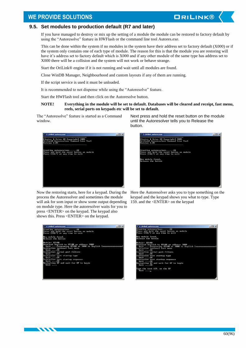
60(96)
9.5. Set modules to production default (R7 and later)
If you have managed to destroy or mix up the setting of a module the module can be restored to factory default by
using the “Autoresolve” feature in HWFlash or the command line tool Autores.exe.
This can be done within the system if no modules in the system have their address set to factory default (X000) or if
the system only contains one of each type of module. The reason for this is that the module you are restoring will
have it’s address set to factory default which is X000 and if any other module of the same type has address set to
X000 there will be a collision and the system will not work or behave strange.
Start the OriLink® engine if it is not running and wait until all modules are found.
Close WinDB Manager, Neighbourhood and custom layouts if any of them are running.
If the script service is used it must be unloaded.
It is recommended to not dispense while using the “Autoresolve” feature.
Start the HWFlash tool and then click on the Autoresolve button.
NOTE! Everything in the module will be set to default. Databases will be cleared and receipt, fast menu,
reels, serial ports on keypads etc will be set to default.
The “Autoresolve” feature is started as a Command
window. Next press and hold the reset button on the module until the Autoresolver tells you to Release the button.
Now the restoring starts, here for a keypad. During the
process the Autoresolver and sometimes the module
will ask for som input or show some output depending
on module type. Here the autoresolver waits for you to
press <ENTER> on the keypad. The keypad also
shows this. Press <ENTER> on the keypad.
Here the Autoresolver asks you to type something on the
keypad and the keypad shows you what to type. Type
159. and the <ENTER> on the keypad
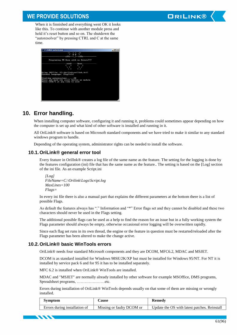
61(96)
When it is finnished and everything went OK it looks
like this. To continue with another module press and
hold it’s reset button and so on. The shutdown the
“autoresolver” by pressing CTRL and C at the same
time.
10. Error handling.
When installing computer software, configuring it and running it, problems could sometimes appear depending on how
the computer is set up and what kind of other software is installed and running in it.
All OriLink® software is based on Microsoft standard components and we have tried to make it similar to any standard
windows program to handle.
Depending of the operating system, administrator rights can be needed to install the software.
10.1. OriLink® general error tool
Every feature in OrilInk® creates a log file of the same name as the feature. The setting for the logging is done by
the features configuration (ini) file that has the same name as the feature.. The setting is based on the [Log] section
of the ini file. As an example Script.ini
[Log]
FileName=C:\Orilink\Logs\Script.log
MaxLines=100
Flags=
In every ini file there is also a manual part that explains the different parameters at the bottom there is a list of
possible Flags.
As default the features always has “.” Information and “*” Error flags set and they cannot be disabled and these two
characters should never be used in the Flags setting.
The additional possible flags can be used as a help to find the reason for an issue but in a fully working system the
Flags parameter should always be empty, otherwise occasional error logging will be overwritten rapidly.
Since each flag set runs in its own thread, the engine or the feature in question must be restarted/reloaded after the
Flags parameter has been altered to make the change active.
10.2. OriLink® basic WinTools errors
OriLink® needs four standard Microsoft components and they are DCOM, MFC6.2, MDAC and MSJET.
DCOM is as standard installed for Windows 98SE/2K/XP but must be installed for Windows 95/NT. For NT it is
installed by service pack 6 and for 95 it has to be installed separately.
MFC 6.2 is installed when OriLink® WinTools are installed.
MDAC and "MSJET" are normally already installed by other software for example MSOffice, DMS programs,
Spreadsheet programs, …………………etc.
Errors during installation of OriLink® WinTools depends usually on that some of them are missing or wrongly
installed.
Symptom Cause Remedy
Errors during installation of Missing or faulty DCOM or Update the OS with latest patches. Reinstall
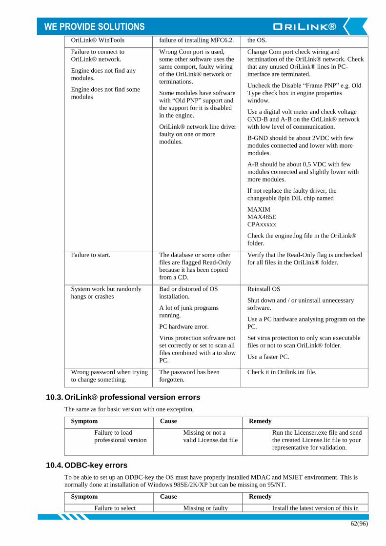
62(96)
OriLink® WinTools failure of installing MFC6.2. the OS.
Failure to connect to
OriLink® network.
Engine does not find any
modules.
Engine does not find some
modules
Wrong Com port is used,
some other software uses the
same comport, faulty wiring
of the OriLink® network or
terminations.
Some modules have software
with “Old PNP” support and
the support for it is disabled
in the engine.
OriLink® network line driver
faulty on one or more
modules.
Change Com port check wiring and
termination of the OriLink® network. Check
that any unused OriLink® lines in PC-
interface are terminated.
Uncheck the Disable “Frame PNP” e.g. Old
Type check box in engine properties
window.
Use a digital volt meter and check voltage
GND-B and A-B on the OriLink® network
with low level of communication.
B-GND should be about 2VDC with few
modules connected and lower with more
modules.
A-B should be about 0,5 VDC with few
modules connected and slightly lower with
more modules.
If not replace the faulty driver, the
changeable 8pin DIL chip named
MAXIM
MAX485E
CPAxxxxx
Check the engine.log file in the OriLink®
folder.
Failure to start. The database or some other
files are flagged Read-Only
because it has been copied
from a CD.
Verify that the Read-Only flag is unchecked
for all files in the OriLink® folder.
System work but randomly
hangs or crashes
Bad or distorted of OS
installation.
A lot of junk programs
running.
PC hardware error.
Virus protection software not
set correctly or set to scan all
files combined with a to slow
PC.
Reinstall OS
Shut down and / or uninstall unnecessary
software.
Use a PC hardware analysing program on the
PC.
Set virus protection to only scan executable
files or not to scan OriLink® folder.
Use a faster PC.
Wrong password when trying
to change something.
The password has been
forgotten.
Check it in Orilink.ini file.
10.3. OriLink® professional version errors
The same as for basic version with one exception,
Symptom Cause Remedy
Failure to load
professional version
Missing or not a
valid License.dat file
Run the Licenser.exe file and send
the created License.lic file to your
representative for validation.
10.4. ODBC-key errors
To be able to set up an ODBC-key the OS must have properly installed MDAC and MSJET environment. This is
normally done at installation of Windows 98SE/2K/XP but can be missing on 95/NT.
Symptom Cause Remedy
Failure to select Missing or faulty Install the latest version of this in
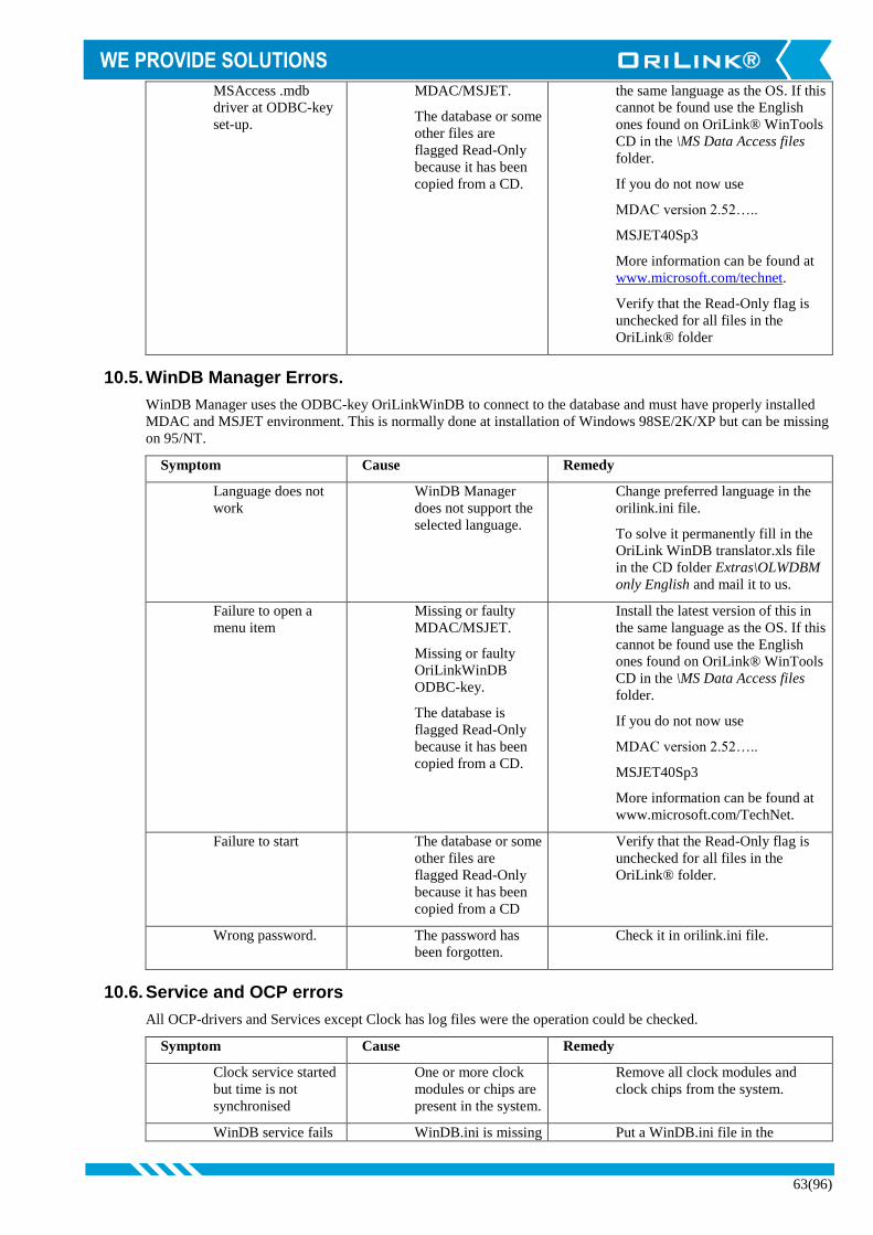
63(96)
MSAccess .mdb
driver at ODBC-key
set-up.
MDAC/MSJET.
The database or some
other files are
flagged Read-Only
because it has been
copied from a CD.
the same language as the OS. If this
cannot be found use the English
ones found on OriLink® WinTools
CD in the \MS Data Access files
folder.
If you do not now use
MDAC version 2.52…..
MSJET40Sp3
More information can be found at
www.microsoft.com/technet.
Verify that the Read-Only flag is
unchecked for all files in the
OriLink® folder
10.5. WinDB Manager Errors.
WinDB Manager uses the ODBC-key OriLinkWinDB to connect to the database and must have properly installed
MDAC and MSJET environment. This is normally done at installation of Windows 98SE/2K/XP but can be missing
on 95/NT.
Symptom Cause Remedy
Language does not
work
WinDB Manager
does not support the
selected language.
Change preferred language in the
orilink.ini file.
To solve it permanently fill in the
OriLink WinDB translator.xls file
in the CD folder Extras\OLWDBM
only English and mail it to us.
Failure to open a
menu item
Missing or faulty
MDAC/MSJET.
Missing or faulty
OriLinkWinDB
ODBC-key.
The database is
flagged Read-Only
because it has been
copied from a CD.
Install the latest version of this in
the same language as the OS. If this
cannot be found use the English
ones found on OriLink® WinTools
CD in the \MS Data Access files
folder.
If you do not now use
MDAC version 2.52…..
MSJET40Sp3
More information can be found at
www.microsoft.com/TechNet.
Failure to start The database or some
other files are
flagged Read-Only
because it has been
copied from a CD
Verify that the Read-Only flag is
unchecked for all files in the
OriLink® folder.
Wrong password. The password has
been forgotten.
Check it in orilink.ini file.
10.6. Service and OCP errors
All OCP-drivers and Services except Clock has log files were the operation could be checked.
Symptom Cause Remedy
Clock service started
but time is not
synchronised
One or more clock
modules or chips are
present in the system.
Remove all clock modules and
clock chips from the system.
WinDB service fails WinDB.ini is missing Put a WinDB.ini file in the

64(96)
to load. or configured wrong.
Missing or not a
valid License.dat file.
The database or some
other files are
flagged Read-Only
because it has been
copied from a CD
OriLink® folder.
Run the Licenser.exe file and send
the created License.lic file to your
representative for validation.
Verify that the Read-Only flag is
unchecked for all files in the
OriLink® folder.
Check WinDB.log file for error
messages.
OCP-driver fails to
load or does not work
properly.
The INI file for it is
missing or
configured wrong.
Missing or not a
valid License.dat file.
The database or some
other files are
flagged Read-Only
because it has been
copied from a CD.
Put the proper INI file in the
OriLink® folder and verify the
configuration.
Run the Licenser.exe file and send
the created License.lic file to your
representative for validation.
Verify that the Read-Only flag is
unchecked for all files in the
OriLink® folder.
Check Log file for the OCP-driver
for error messages.
OCP-driver cannot
connect to DMS
system.
Wrong configuration
in INI file.
Customer network
error.
DMS server name
and/or IP-address
changed.
Network folders
sharing not properly
set or changed.
Verify the configuration.
Check customer network
functionality.
Verify the DMS server name and/or
IP-address.
Verify network folder sharing.

65(96)
11. Advanced features
11.1. Module PNP update priority (Large systems).
The OriLink® communication network is of collation type like Ethernet, the first module that demands net network
gets it and the others have to wait. If all modules tries to issue or answer to a general PNP update request in a system
with a lot of modules there would be a lot of net requests at the same time during a very short period of time.
OriLink® uses PNP update priority based on the address of the module to spread this over a longer time period.
In a large system with a lot of modules it is recommended to set the addresses of the modules so that the update
priority is spread evenly. This is called fragmented updating.
The PNP update priority of a module is based on the first and the last figure of the address and a lower figure has
higher priority than a higher.
MPDM PM KP LED Vacant Vacant Vacant TCM Vacant
Address X=1 X=2 X=3 X=4 X=5 X=6 X=7 X=8 X=9
X??0 30 34 38 42 46 50 54 58 62
X??1 31 35 39 43 47 51 55 59 63
X??2 32 36 40 44 48 52 56 60 64
X??3 33 37 41 45 49 53 57 61 65
X??4 30 34 38 42 46 50 54 58 62
X??5 31 35 39 43 47 51 55 59 63
X??6 32 36 40 44 48 52 56 60 64
X??7 33 37 41 45 49 53 57 61 65
X??8 30 34 38 42 46 50 54 58 62
X??9 31 35 39 43 47 51 55 59 63
The OriLink® engine always has a PNP update priority of 10.
This is an example of how setting the address sets the priority.
Priority Module Address Comments
31 MPDM 1001
The order between this two will be random MPDM 1011
32
MPDM 1092
The order between this three will be random MPDM 1032
MPDM 1046
33 MPDM 1023
The order between this two will be random MPDM 1013
38 KP 3004
The order between this two will be random KP 3074
41 KP 3013
The order between this two will be random KP 3023
43 LED 4001
59 TCM 8005
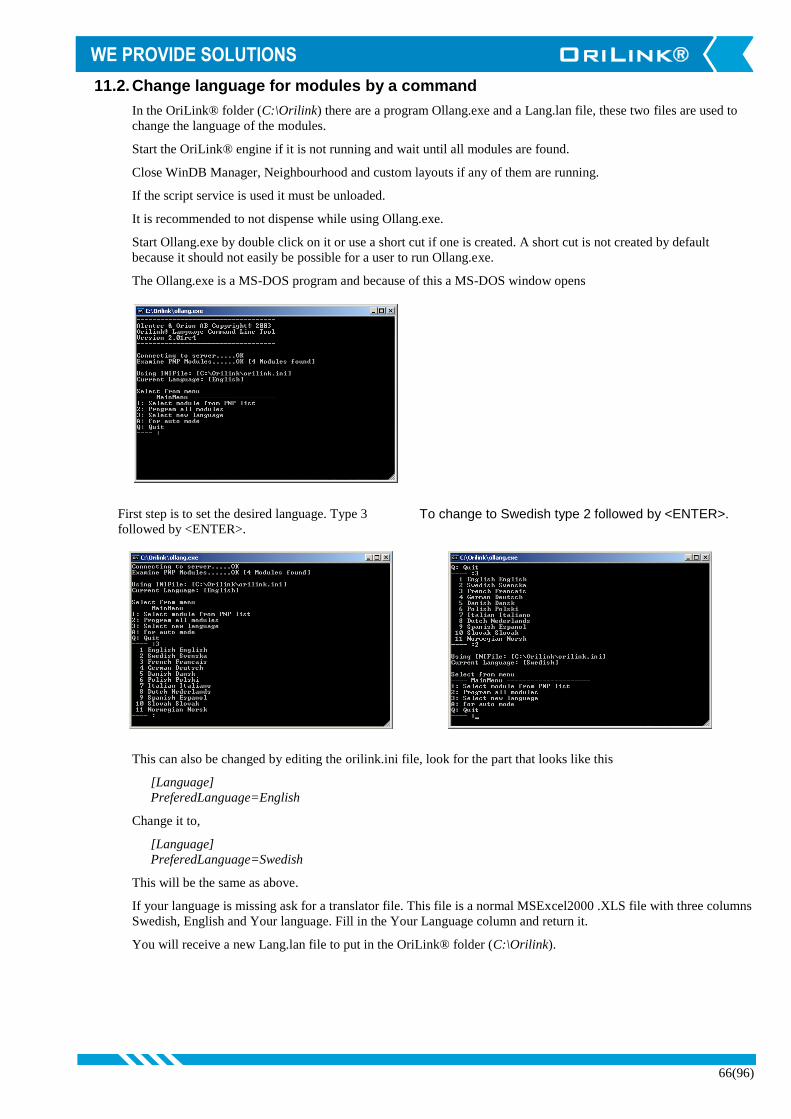
66(96)
11.2. Change language for modules by a command
In the OriLink® folder (C:\Orilink) there are a program Ollang.exe and a Lang.lan file, these two files are used to
change the language of the modules.
Start the OriLink® engine if it is not running and wait until all modules are found.
Close WinDB Manager, Neighbourhood and custom layouts if any of them are running.
If the script service is used it must be unloaded.
It is recommended to not dispense while using Ollang.exe.
Start Ollang.exe by double click on it or use a short cut if one is created. A short cut is not created by default
because it should not easily be possible for a user to run Ollang.exe.
The Ollang.exe is a MS-DOS program and because of this a MS-DOS window opens
First step is to set the desired language. Type 3
followed by <ENTER>. To change to Swedish type 2 followed by <ENTER>.
This can also be changed by editing the orilink.ini file, look for the part that looks like this
[Language]
PreferedLanguage=English
Change it to,
[Language]
PreferedLanguage=Swedish
This will be the same as above.
If your language is missing ask for a translator file. This file is a normal MSExcel2000 .XLS file with three columns
Swedish, English and Your language. Fill in the Your Language column and return it.
You will receive a new Lang.lan file to put in the OriLink® folder (C:\Orilink).

67(96)
Second step is to program all modules to the preferred
language, here English. Type 2 followed by
<ENTER>.
This is how it looks when it is finished. Type Q followed by <ENTER> to quit.
It is also possible to have different languages in different modules this is done by setting the language to desired one
and then use menu item 1.
When the preferred language is set, here English,
Type 1 followed by <ENTER>. Select module from
PNP list, here MPDM100 with address 1005. Type 1
followed by <ENTER>.
This is how it looks when it is finished. Type Q followed by <ENTER> to quit.
11.3. Set modules to production default by a command
If you have managed to destroy or mix up the setting of a module the module can be restored to factory default by
using the OlLang.exe or directly by the Autores.exe program.
This can be done within the system if no modules in the system have their address set to factory default (X000) or if
the system only contains one of each type of module. The reason for this is that the module you are restoring will
have it’s address set to factory default which is X000 and if any other module of the same type has address set to
X000 there will be a collision and the system will not work or behave strange.
Start the OriLink® engine if it is not running and wait until
all modules are found.
Close WinDB Manager, Neighbourhood and custom
layouts if any of them are running.
If the script service is used it must be unloaded.
It is recommended to not dispense while using Autores.exe.
Start Ollang.exe by double click on it or use a short cut if
one is created. A short cut is not created by default because
it should not easily be possible for a user to run Ollang.exe.
The Ollang.exe is a MS-DOS program and because of this a
MS-DOS window opens
NOTE! Everything in the module will be set to default. Databases will be cleared and receipt, fast menu,
reels, serial ports on keypads etc will be set to default.

68(96)
First step is to start the “autoresolver”. Type A
followed by <ENTER>. Nest press and hold the reset button on the module until Ollang tells you to Release the button.
Now the restoring starts, here for a keypad. During the
process Ollang and sometimes the module will ask for
som input or show some output depending on module
type. Here Ollang waits for you to press <ENTER> on
the keypad. The keypad also shows this. Press
<ENTER> on the keypad.
Here Ollang asks you to type something on the keypad
and the keypad shows you what to type. Type 159. and
the <ENTER> on the keypad
When it is finnished and everything went OK it looks
like this. To continue with another module press and
hold it’s reset button and so on. The shutdown the
“autoresolver” press CTRL and C at the same time.
Then to shutdown Ollang type Q followed by <ENTER>.
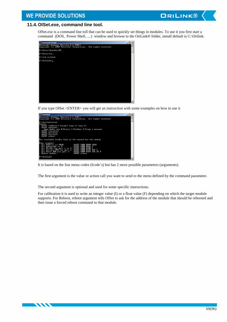
69(96)
11.4. OlSet.exe, command line tool.
OlSet.exe is a command line toll that can be used to quickly set things in modules. To use it you first start a
command (DOS, Power Shell, ....) window and browse to the OriLink® folder, install default is C:\Orilink.
If you type OlSet <ENTER> you will get an instruction with some examples on how to use it
It is based on the fast menu codes (fcode’s) but has 2 more possible parameters (arguments).
The first argument is the value or action call you want to send to the menu defined by the command parameter.
The second argument is optional and used for some specific instructions.
For calibration it is used to write an integer value (I) or a float value (F) depending on which the target module
supports. For Reboot, reboot argument tells OlSet to ask for the address of the module that should be rebooted and
then issue a forced reboot command to that module.

70(96)
11.5. Creating submenus in the engine control menu
The first step is to create a Run folder in the OriLink® main folder, this is done during installation for R7 and later.
C:\Orilink\Run
Now create some usable folders in the C:\Orilink\Run folder like this,
C:\Orilink\Run\Data
C:\Orilink\Run\Layouts
If the engine control menu is opened after this is done there will be two new submenus in the Control menu, Data
and Layouts.
Now we shall put some useful things in these two items.
Put a short cut for the OriLinkWinDB.exe file in the Data folder and put a short cut for the HwMon2.exe in the
Layouts folder.
If the engine control menu is opened after this is done the result will be this.
Left-click on a short cut and the software will start.
This is a good way to create an OriLink® customized user menu.
You can change the names for the submenu items by changing the names of the short cuts in the folders.
11.6. Design a custom system graphic layout (HwMon2)
A customer specific monitoring system layout could be created by the use of the software HWMon2.exe. HWMon2
does exactly the same as HWMon (The OriLink® Neighbourhood in R6 and earlier) but with HWMon2 the
different parts of the system can be arranged to look similar to the actual workshop.
Creating an OriLink Layout file with the extension .OLL does this.
You can have several different layout files for the same workshop for example one for each working bay.
It is possible to have multiple layouts shown at the same time but remember that they are real-time software and
uses computer power.
11.6.1. Create a new layout file.
First start by click HWMon2-Create New Layout in
the Start>Orilink menu this will make the default
HWMon2 start window to appear.
First save the layout to give it a name. Remember to
save the layout file regulary as the layout grows.

71(96)
Browse to a suitable folder for example C:\Orlink or
C:\Orilink\Layouts if doesn’t exist create one and
type in a name, here Workshop. Then click the Save
button.
Now we can start selecting what to show in the
Workshop Layout.
Open the Select Tool. Viewing the select tool is
toggled, select it once shows it select it again hides it.
The red square shows the start-up size of the layout in
normal run time mode. It can be sized to fit the
amount of controls by left click hold and drag the
small squares on the left and lower boarders.
Then open the Local Server, click the small “+” sign.
A computer name might also be showing here, this is
explained under chapter “Creating a Client layout
file”. The module selector works in a similar way as
the Windows explorer. If you single click an item it is
opened, if there is something in it and if you double
click an item it is selected if possible.
Now open a module, click the small “+” sign. Here a
MPDM.
Now select the graphic control for the wanted part of
the module by doubble clicking on it in the module
selector. Here Port1 of the MPDM.

72(96)
Add moore graphic controls in the same way. When
the HWMon2 graphic window “top row” is getting ful
select the controls using the mouse.
Place the cursor above and to the left of the white
small square of the first “reel” press and hold the left
mouse button. Release the mouse button when the
created rectangle covers the desired controls.
The controls can be moved in three different ways.
Using the keyboard arrow keys.
Typing in the coordinates in the table view to the left
Using the mouse.
Here we will show how to move them with the mouse. The controls are grabbed by the “handle”, the small
white square in the upper left corner of a control. If moore than one control are selected place the cursor over
one of the handles, hold down the keyboard control button. Press and hold the left mouse button and drag the
controls to were you want them and release the mose and then the control button.
Like this. Here we move the controls down to free up space for
moore controls. To unselect controls left click on the
graphic background.
Now click on the Module Selector Reset button to set
the insertion point for new controls to the upper left
corner of the HWMON2 graphic window. Then add
some moore controls.
If the service WinDB.dll is loaded and there are
configured tanks in the PC database Contols for these
tanks are found under OtherStuff>WinDB in the
module selector.
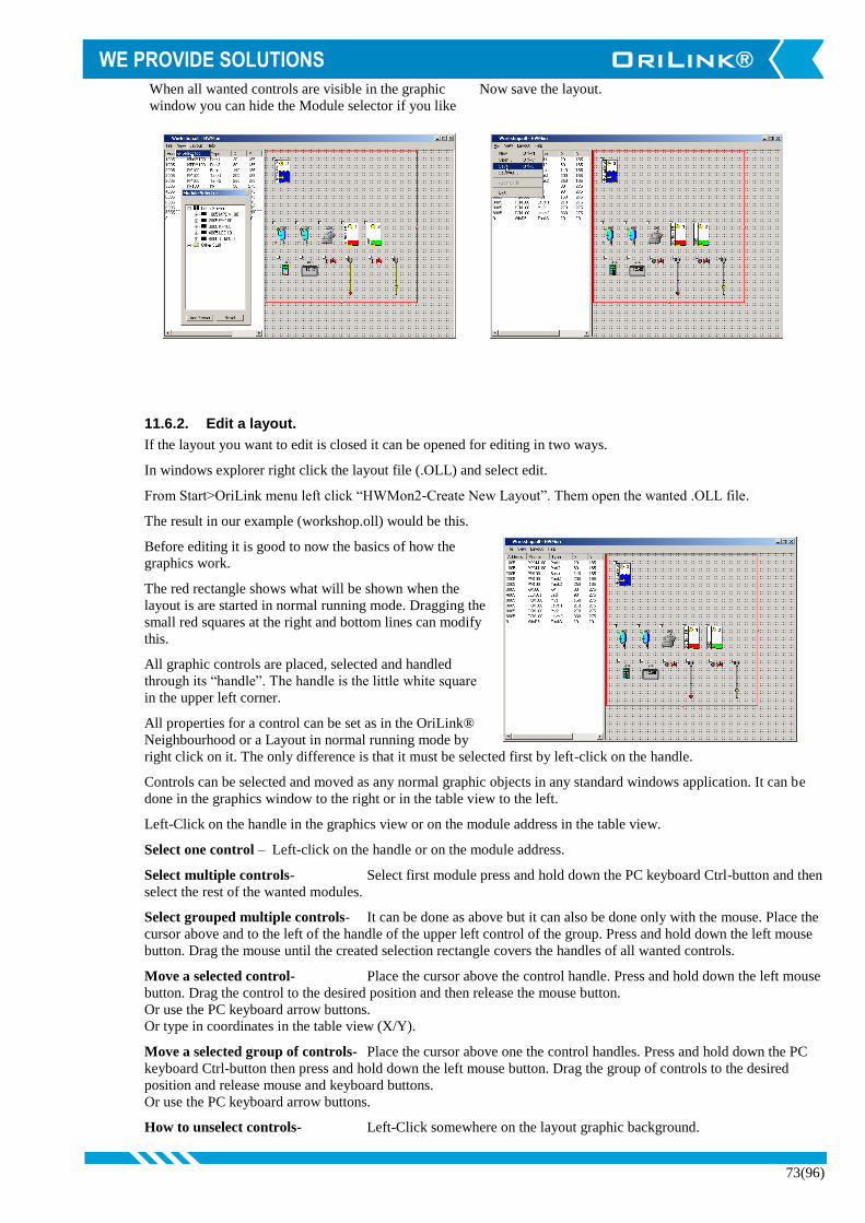
73(96)
When all wanted controls are visible in the graphic
window you can hide the Module selector if you like
Now save the layout.
11.6.2. Edit a layout.
If the layout you want to edit is closed it can be opened for editing in two ways.
In windows explorer right click the layout file (.OLL) and select edit.
From Start>OriLink menu left click “HWMon2-Create New Layout”. Them open the wanted .OLL file.
The result in our example (workshop.oll) would be this.
Before editing it is good to now the basics of how the
graphics work.
The red rectangle shows what will be shown when the
layout is are started in normal running mode. Dragging the
small red squares at the right and bottom lines can modify
this.
All graphic controls are placed, selected and handled
through its “handle”. The handle is the little white square
in the upper left corner.
All properties for a control can be set as in the OriLink®
Neighbourhood or a Layout in normal running mode by
right click on it. The only difference is that it must be selected first by left-click on the handle.
Controls can be selected and moved as any normal graphic objects in any standard windows application. It can be
done in the graphics window to the right or in the table view to the left.
Left-Click on the handle in the graphics view or on the module address in the table view.
Select one control – Left-click on the handle or on the module address.
Select multiple controls- Select first module press and hold down the PC keyboard Ctrl-button and then
select the rest of the wanted modules.
Select grouped multiple controls- It can be done as above but it can also be done only with the mouse. Place the
cursor above and to the left of the handle of the upper left control of the group. Press and hold down the left mouse
button. Drag the mouse until the created selection rectangle covers the handles of all wanted controls.
Move a selected control- Place the cursor above the control handle. Press and hold down the left mouse
button. Drag the control to the desired position and then release the mouse button.
Or use the PC keyboard arrow buttons.
Or type in coordinates in the table view (X/Y).
Move a selected group of controls- Place the cursor above one the control handles. Press and hold down the PC
keyboard Ctrl-button then press and hold down the left mouse button. Drag the group of controls to the desired
position and release mouse and keyboard buttons.
Or use the PC keyboard arrow buttons.
How to unselect controls- Left-Click somewhere on the layout graphic background.

74(96)
Worshop.oll opened in edit mode. First move the LED control. Select it by Left-Click on
the handle. Move it by Left-Click and hold on the
handle.
Drag the control to the desired spot and
release the left mouse button.
Now try a multiple spread select example.
Now do a multiple group select, here the
two reels.
This is the result. The left reel with a
thicker border is the primary select.

75(96)
Now move the group. Move it by first press
and hold PC keyboard Ctrl-button then left-
click and hold on the primary select handle.
Drag the group to the desired position
Release mouse button and the Ctrl-Button.
Then left-click somewhere on the
background to unselect the controls.
Now do the same for the remaining
controls. The result could be something
like this. To your help there are also advanced
alignment tools and a possibility to use a
grid.
11.6.3. Modifying the layout background
By modifying the background of a layout it can be personalized to meet users, workshop, oil
company,…., etc. demands.
Almost any bitmap file can be used. It can be a nice picture, a company log, a graphic schematic of pipe
works,….etc.

76(96)
First create the bitmap with any .BMP
software. For example MSPaint that comes
with Windows. Here SampleLogo.bmp
Then open the layout menu and click on Select
Background Image.
Select the file SampleLogo.bmp and click on
Open.
The default result will be.
To make it look good use the layout menu
item Properties.
Here you can select how the background
image should be placed.

77(96)
Choose bottom Right and click OK. This will be the result.
Now save the layout and close the layout edit
mode.
11.6.4. Open a custom layout file
When a custom layout is created and looks like it should it can be started in normal running mode in
several ways.
In Windows explorer by double click on the file.
Double click on a created Short Cut.
Single click on a created short cut in the Windows fast menu.
Select it from the OriLink® engine control menu. See chapter “Creating submenus in the engine control
menu”
This is shown here.
Right-click on the engine window
background.
The normal running mode will open.
Observe that the bottom right placement
setting is done against the normal running
mode.

78(96)
11.6.5. Creating a Client layout file.
OriLink® WinTools has full support for a “Client-Server” scenario. If this is the case the best thing to do
when creating a layout file is to do it on the OriLink® Server. The OriLink® server is the PC that is
running the engine and has all the OriLink® hardware connected.
If the server is set-up for remote access
the Module selector will have two, or
more, servers to select graphic controls
from. In the above we have used the
“Local Server” but if we want to use the
created layout file on client PC’s in the
network we must select the graphic
controls from the public server instead.
The public server is the one with the
same name as the OriLink® Server PC.
In this example the name of the PC
running engine.exe is OriLink-PC.
In Windows Vista, 7, 8, 8.1,.... Microsoft has made the finding of computers in a network not so easy so
if you do not find your OriLink® server in the list you can use the “Add server” feature. Click the <Add
server> button in the Module selector and type in the network name or IP address of the OriLink® server
If you drag the separator between the table view and the graphic view to the right you will se an extra
column named Server. In this column you will se the name of the server that have the physical hardware
that you have selected to be in the layout.
A layout can have controls from multiple servers.
See also the chapter “OriLink® Server-Client Set-up.”

79(96)
11.7. Orion Common Platform (OCP)
The Orion Common Platform is a platform developed for interconnections between different Alentec & Orion AB
monitoring systems and customer DMS systems. DMS stands for Data Management Systems.
Today all Alentec & Orion Systems OilMon800, OilMonPC-Win and OriLink® can be connected to the OCP.
What can be done with a connection to a DMS?
With a connection between a monitoring system and a DMS system it is possible to,
Verify that a work order/job/serial/part number typed in on a keypad by a user really exists and is valid for
dispensing. This is called job number validation.
Transfer information of a made dispenses to the DMS system. This can be used to put the dispensed oil on an
invoice or for historical track ability within a quality system.
Different DMS system can do one of them or both.
OriLink® can do both
11.7.1. Different ways of connections
There are a lot of different ways to make a connection for example,
ASCII text files (or other formats)
This is based on one valid job number file and one made transactions file.
The DMS system updates the job number file so it only contains valid job numbers, one on each row
of the file. It also reads made transactions from the transaction file, one transaction on each row in the
file. When a transaction is read it is also removed from the file to eliminate the risk of double read.
OriLink® validates the typed job number against the job number file and put new transactions in the
transaction file.
The information and format of it and the names of the files can be set through an ini file.
ODBC
This is based on the same technique that OriLink® uses for the internal database handling.
Valid job numbers and transactions can be inserted or extracted through an ODBC key either by the
OriLink® to the DMS system or by the DMS system to the OriLink® database.
Real-Time Client-Sever
This is based on that the OriLink® system acts as a client to the DMS system and when the user types
in a job number he logs in to the DMS system and asks if it is valid or not.
When a transaction is made the OriLink® system logs on to the DMS system and sends the
transaction.
The OriLink® system can use almost any kind of connection.
11.7.2. How does it work
There are two things that is needed to make a connection,
The DMS system must have a way to communicate this type of information.
There must be an OCP-driver that supports this way.
Most DMS systems of today have a way to do this and we develop the OCP-driver.
11.7.3. Existing OCP-drivers (040924)
We are continuously developing new drivers and the ones we have today are,
Generic Text, Generic ODBC (former name Generic SQL), TACDIS 5/6, GDS 2.1, KOBRA 2,
DRACAR+, WinAssist, ROWIL, Connex, SMC, Automaster, Acosy, Kerridge,
If your DMS system is not in the list and cannot use one of the generic ones contact us because there are
more in the pipeline.
11.7.4. How to install an OCP-driver
The driver comes on a diskette. CD or as a zipped file package by mail. It is installed by running a .BAT
file called Orilink.bat, if OriLink is installed in the default folder C:\Orilink, If not the files has to be
copied manually.

80(96)
The OCP-driver is license protected through the License.dat file for OriLink®. If no License.dat exists in
the OriLink® folder run the software Licenser.exe. See chapter “Convert BASIC version to Professional
version”.
If a License.dat exists we probably have in our database tell us to update it to enable the desired OCP-
driver.
Open the INI file of the driver with notepad and adjust the settings. The manual for this is inside the INI
file.
11.7.5. How to load an OCP-driver
An OCP-driver is loaded either from the OriLink® engine window or by editing the WinDB.ini file in the
OriLink® folder C:\Orilink.
Open the engine window. Right-click it and select properties.
The result will be like this. Right-click on OriLink® WindowsDB… and
select properties.
Or directly. The WinDB service properties window
opens.
By checking the “Use PartNumber in OCP1”
checkbox the fluid part number will be transferred
instead of the fluid name. This feature only exists in
WinDB Service 108RC2 or higher.
Right-click Loaded OCP’s window and select
Add New OCP.
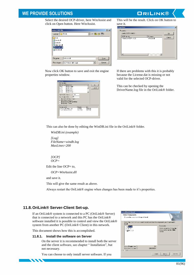
81(96)
Select the desired OCP-driver, here WinAssist and
click on Open button. Here WinAssist.
This will be the result. Click on OK button to
save it.
Now click OK button to save and exit the engine
properties window.
If there are problems with this it is probably
because the License.dat is missing or not
valid for the selected OCP-driver.
This can be checked by opening the
DriverName.log file in the OriLink® folder.
This can also be done by editing the WinDB.ini file in the OriLink® folder.
WinDB.ini (example)
[Log]
FileName=windb.log
MaxLines=200
[OCP]
OCP=
Edit the line OCP= to,
OCP=WinAssist.dll
and save it.
This will give the same result as above.
Always restart the OriLink® engine when changes has been made to it’s properties.
11.8. OriLink® Server-Client Set-up.
If an OriLink® system is connected to a PC (OriLink® Server)
that is connected to a network and this PC has the OriLink®
software installed it is possible to control and view the OriLink®
system from another PC (OriLink® Client) in this network.
This document shows how this is accomplished.
11.8.1. Install the software on Server
On the server it is recommended to install both the server
and the client software, see chapter “ Installation”, but
not necessary.
You can choose to only install server software. If you

82(96)
want to only install server software uncheck the client line before clicking the Next-button.
If only the server software is installed you will not be able to create layouts on the server.
Typical situations were you might want to only install the server software is if the server does not have a
display or keyboard.
Start the OriLink® Engine. Right-click on the engine window background and select properties.
Uncheck the item “Disable Broadcast Server” Left-click the OK-button.
Shut down the engine.
11.8.2. OriLink® Server set-up (Windows98SE)
Install the OriLink® WinTools software.
Start regedit
NOTE! Altering this setting will have a great impact on security issues, and should not be done without
discussion with a network/computer technician!
NOTE! It is very important that nothing else is changed, it could give the result that WINDOWS stops
working !
Select Run from the start menu. Regedit started
Go to \HKEY_LOCAL_MACHINE\Software\
Microsoft\OLE. Double click on
“EnableRemoteConnect”.
Change the “N” to “Y”.
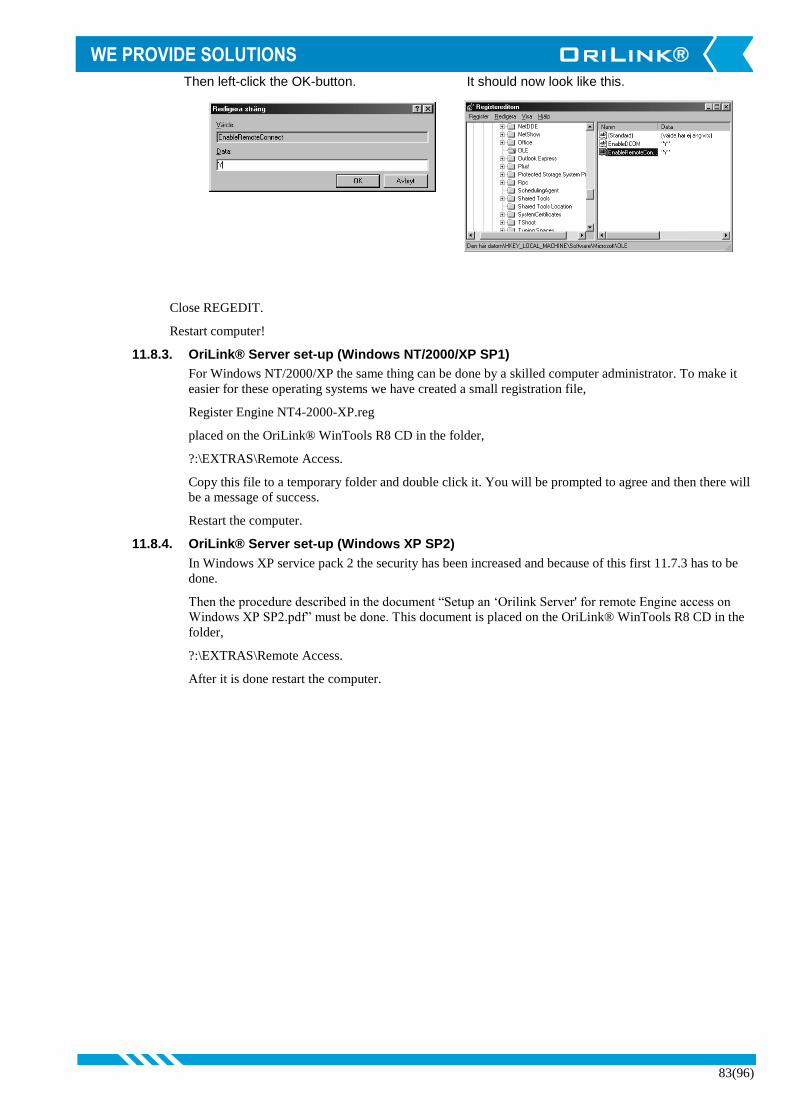
83(96)
Then left-click the OK-button. It should now look like this.
Close REGEDIT.
Restart computer!
11.8.3. OriLink® Server set-up (Windows NT/2000/XP SP1)
For Windows NT/2000/XP the same thing can be done by a skilled computer administrator. To make it
easier for these operating systems we have created a small registration file,
Register Engine NT4-2000-XP.reg
placed on the OriLink® WinTools R8 CD in the folder,
?:\EXTRAS\Remote Access.
Copy this file to a temporary folder and double click it. You will be prompted to agree and then there will
be a message of success.
Restart the computer.
11.8.4. OriLink® Server set-up (Windows XP SP2)
In Windows XP service pack 2 the security has been increased and because of this first 11.7.3 has to be
done.
Then the procedure described in the document “Setup an ‘Orilink Server' for remote Engine access on
Windows XP SP2.pdf” must be done. This document is placed on the OriLink® WinTools R8 CD in the
folder,
?:\EXTRAS\Remote Access.
After it is done restart the computer.

84(96)
11.8.5. OriLink® Client Set-up.
Install only the OriLink® WinTools client software
on the client PC. Uncheck the Server line before
left-click on the Next-button.
The same rules of BASIC / Professional version as
for the normal installation applies to a client
installation.
11.8.6. Start Up.
Start OriLink® engine on the OriLink® Server.
Start the software HWMon.exe on the OriLink®
Client PC and select the proper server from the list
and click on the Save-button. This will open a remote OriLink® neighbourhood session.
If you have made a custom layout as described in chapter “Creating a Client layout file.” You can put this
layout file in the c:\Orilink folder of the client PC and double click on the file. This will start a client
session of this layout.
11.9. Importing data to Microsoft EXCEL
Importing data from the OriLink® PC database to Microsoft EXCEL is very simple. Using the query wizard in MS
EXCEL and the OriLinkWinDB ODBC key, see chapter 7.2, does this.
Start MSExcel and open a new spreadsheet. Choose “Data” menu and choose “New query”.
Choose OriLinkWinDB and click OK Choose the tables you need and open it by
clicking on the “+” sign

85(96)
Select the desired fields by marking them
and then click on >. When all desired fields
are selected click on <NEXT> button.
Here you can filter the data and then click Next.
Here you can sort your data and then click
Next.
Here you can choose where you want to do
with the data and if you want to save the query,
then click Finnish.
If you choose to return the data to MSExcel
you must decide where it should be placed.
“Left-Click” a cell in the spreadsheet and the
“Left-Click” OK.
Now you can design you report with MSExcel.
Finished.
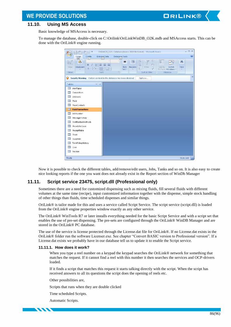
86(96)
11.10. Using MS Access
Basic knowledge of MSAccess is necessary.
To manage the database, double-click on C:\Orilink\OriLinkWinDB_O2K.mdb and MSAccess starts. This can be
done with the OriLink® engine running.
Now it is possible to check the different tables, add/remove/edit users, Jobs, Tanks and so on. It is also easy to create
nice looking reports if the one you want does not already exist in the Report section of WinDb Manager
11.11. Script service 23475, script.dll (Professional only)
Sometimes there are a need for customized dispensing such as mixing fluids, fill several fluids with different
volumes at the same time (recipe), input customized information together with the dispense, simple stock handling
of other things than fluids, time scheduled dispenses and similar things.
OriLink® is tailor made for this and uses a service called Script Service. The script service (script.dll) is loaded
from the OriLink® engine properties window exactly as any other service.
The OriLink® WinTools R7 or later installs everything needed for the basic Script Service and with a script set that
enables the use of pre-set dispensing. The pre-sets are configured through the OriLink® WinDB Manager and are
stored in the OriLink® PC database.
The use of the service is license protected through the License.dat file for OriLink®. If no License.dat exists in the
OriLink® folder run the software Licenser.exe. See chapter “Convert BASIC version to Professional version”. If a
License.dat exists we probably have in our database tell us to update it to enable the Script service.
11.11.1. How does it work?
When you type a reel number on a keypad the keypad searches the OriLink® network for something that
matches the request. If it cannot find a reel with this number it then searches the services and OCP-drivers
loaded.
If it finds a script that matches this request it starts talking directly with the script. When the script has
received answers to all its questions the script does the opening of reels etc.
Other possibilities are,
Scripts that runs when they are double clicked
Time scheduled Scripts.
Automatic Scripts.

87(96)
Scripts that can be started with dynamic input parameters. This type can be used both locally and remote.
Through for example a .bat file, a short-cut or from an external application.
11.11.2. What kind of script language is used
The OriLink® script service uses a script language called CSL. It is an Open License script language and is
used by a large number of users over the world. This means that the script interpreter are free to use for
anyone and that all fixes of it must be reported to other users. It also means that information about how to
write CSL scripts can be found for free on the Internet.
The License protection for the OriLink® script service is not for the CSL interpreter it is for the connection
between the OriLink® system and the interpreter.
11.11.3. How to write scripts
Scripts are written using a simple text file editor such as notepad. See OriLink® separate Script manual for
details.
12. Using MPDM as TCM100 (Simple tank controller)
If analogue sensors are not needed A MPDM100 hardware can be flashed with a TCM100 software and language. It is
also recommended to set its address to 8??? So it is shown among tank controllers and not among MPDM’s.
To change the software in a chip it must first be flashed to a CO
chip, see chapter “9.3 How to change module type in a flash
chip”. Then select the TCM100xx... you want to use and flash the
module.
Then re-flash the language of the module so it get’s the TCM100
language.
When it is all done the result will be something like this.
In HwFlash
Properties
In PNP array
In
Neighbourhood
The result is a TCM module with optional connector support instead of analogue sensor support. That is why all
settings associated with analogue sensor support are disabled, greyed out. See chapter “6.13.5 Port[n] properties” for
detailed information on settings

88(96)
13. Using MPDM/TCM as a PLC (Programmable Logic Controller)
If the MPDM/TCM is equipped with a FLASH chip and the software version is 1.00.09 or later PLC code can be used
to customize the functionality. To be able to input PLC code OriLink® WinTools R8 or later is needed. There are no
needs for a PC to use the MPDM as a PLC only to program it. The PLC code is built on “ladder” code/diagram.
NOTE! Only about 244 characters of code can be used.
For some unknown reasons you cannot have 53 characters in one row, more or less is fine. If
the needed code has 53 characters add enter at the end of the row or split it on two rows.
13.1. Possible Inputs / Outputs
Device Direction Type Physical location PCB
p1o-p4o Output Control max 1.25 [A] 5-pole port connector
p1ps-p4ps Input Signal (Pre-Set, MaxV) 5-pole port connector
P1close-p4close Input Signal (Close port) 5-pole port connector
p1a-p4a Input Signal 5-pole port connector
p1b-p4b Input Signal 5-pole port connector
i1p-i4p Input Analogue 0-100 % 2-pole analogue
connector 2030291A
p1s-p4s Input (Read) Detect status Internal
rc0-rc2 Input/Output Signal Optional 6-pole
connector 2030262D
re0-re2 Input/Output Signal Optional 6-pole
connector 2030262D
r1-r9 Input/Output Virtual relays Internal
r1tSS-R9tSS Input/Output Virtual timer relays Internal
init Start bit Internal
sopen Input Detect status Key switch
NOTE! Cyclic dispense mode uses pins of the optional connector as error warning outputs.
Port 1 uses rc0
Port 2 uses rc1
Port 3 uses rc2
Port 4 uses re0
So make sure not to mix PLC and Cyclic dispense mode for the same pin.
13.2. Supported operations
LD [NOT] i Loads the C register with value of device “i”.
AND [NOT] i Logic AND of C and the value of device “i”, the result is stored in C
OR [NOT] i Logic OR of C and the value of device “i”, the result is stored in C
XOR [NOT] i Logic XOR of C and the value of device “i”, the result is stored in C
OUT [NOT] o Loads device “o” with the data in the register C
13.3. Sample PLC coded functions
To make it easier to start up the use of the PLC feature this chapter gives some examples of the use of it.
13.3.1. Activate p4o with p4a for 60 s use r1
LD p4a OUT r1t60
LD r1 OUT p4o
13.3.2. Activate p4o with p4a for 10 s, if p4b is OFF Use r1 and deactivate p4o
LD p4a OUT r1t10

89(96)
LD r1 AND NOT p4b OUT p4o
13.3.3. Flipp-flopp for p3o
LD p3a OR p3o AND NOT p3b OUT p3o
13.3.4. Timed cascade coupling of Port1.
Description
(P2=ON) when P1 is ON plus 5 s (Prolonged MV1 pulse)
(P3=ON) when P2 goes OFF plus 5 s (Pulse after prolonged MV1 pulse)
(P4=ON) when P3 goes OFF plus 5 s
Code
LD p1o OUT r1t5
LD r1 OUT r2t5
LD r2 OUT r3t5
LD r3 OUT r4t5
LD r1 OUT p2o
LD r2 AND NOT r1 OUT p3o
LD r3 AND NOT r2 OUT p4o
13.3.5. Start a pump p4o if the system is opened and activate p3o if it is closed
LD sopen OUT p4o OUT NOT p3o
13.3.6. Start control for a system with two pumps
Description
Start the pump p3o if the system is online.
Start the pump p4o if the system is online and the safety switch rc0 is ON
Code
LD sopen OUT p3o AND rc0 OUT p4o
13.3.7. Simple analogue controller with hysteresis
Description
A temperature regulator on Port 1 with hysteresis, here 10%, which starts the heater when the sensor
reading is below 25% of the range and shuts it down when it is over 35%. With heat-up override if you
press push button on Input B.
Code
LD i1p<25 OR p1o AND i1p<35 OR p1b OUT p1o
13.3.8. Equip MPDM and or TCM with PLC chip software
If a complete MPDM or aTCM should be used only for PLC control it can be flashed with a PLC specific
software. Then the port graphics and properties changes to more general symbols and names. The address
range for PLC modules is 5000-5999.

90(96)
13.3.8.1. PLC100 (a MPDM flashed with PLC100 software)
When MPDM hardware is flashed with PLC100 software and language the Port graphics and Properties
are changes to more general symbols.
The greyed parameters are disabled since there is no hardware support for
analogue sensor on a MPDM board.
The RC and RE graphics shows status of the optional connector I/O pins.
13.3.8.2. PLC200 (a TCM flashed with PLC200 software)
When TCM hardware is flashed with PLC200 software and language the Port graphics and Properties are
changes to more general symbols.
The default mode is “Invert function” and “level” but by checking the
parameter “Interval” the graphics will show interval instead.
Like this

91(96)
14. Cyclic dispense mode
This can be used to make timed dispenses with a warning signal output if it fails.
Enabling cyclic dispense mode for a MPDM port.
In the OriLink® neighbourhood right-click the reel/port
you want to use.
Then select Properties from the menu.
The parameters marked yellow controls this mode.
Checking “Cyclic dispense mode”, enables it.
The timeout parameter sets how often dispensing should be made, it can be
between 1 – 255 minutes.
The “Max volume” parameter defines how much that should be dispensed each
time.
The unit of the dispense depends on the calibration, parameter “PPU” (Pulses
Per Unit)
To disable standard manual dispensing the Group can be set to <None>.
After saving the setting by clicking <OK> the module has to rebooted for the
change to be activated. To do that select “Reboot Module” from the properties
menu.
As soon as the module has rebooted, the scheduled dispensing starts.
14.1. How to get a warning signal for failed dispense.
On newer (manufactured after 2007) MPDM’s there is a
foot print for an Optional connector. A dispense port will
send warning signal on a optional connector pin by setting
it to low (“GND”)
Port 1 -> RC0
Port 2 -> RC1
Port 3 -> RC2
Port 4 -> RE0
The status of the optional connector can also be seen in the OriLink graphics. Green when the
pin is high and Red when the pin is low.
If a cyclic dispense does not detect pulses within 30 seconds it times-out and set the
corresponding I/O pin low and shows red in the graphics.

92(96)
Each pin is capable of pulling at least 10mA to ground so a simple diode based
warning indicator for Port one could be like this.
If control of larger currents or a potential free signal is wanted a transistor or a TTL to
power a relay must be used.
14.2. How to get a record/report of dispenses.
If a “DB Address” is set, for example to a PC database (2999) each dispense will be
stored in the targeted database
with CDM as job number so they can be separated from regular dispenses.
There will also be a stop code where 0 means OK and 2 means inactivity time-out.
15. Pre-programmed amounts with a MPDM
A MPDM can be configured as one dispense point with 5(4) or 7(6) programmable pre-set volumes. Connecting Port1
B or Port2 A, and so on to Port4 B low, activates these options. This can be done with an external power switch or some
other control equipment like a PLC. Status signals about an initiated dispense can be received; status shows “Dispense
successful”, “Dispense error”, and ”Dispensing...”
You can also activate a dispense point using a regular KeyPad. A LED display can be used to monitor dispenses and a
printer module or PC can be used to store and print the result.
15.1. Connect a MPDM to dispense pre-programmed amounts
Connect meter and solenoid valve to MPDM Port1:
NOTE! With one meter pulse train input
you get 7 possible presets.
With two meter pulse train input
you get 6 possible presets.
Connect momentary switches or some other control
equipment between GND and the Input for the pre-
programmed option (max 7(6)) as shown in the
table to the right.
15.2. Configure a MPDM to dispense pre-programmed amounts
The MPDM ports are configured as follows.
Port1: INP B as trigger, add 256 to mask
Set PPU to the PPU for the used meter
Set MaxV to desired Preset 1
Port2: INP B as trigger, add 256 to mask
Set PPU to 0 (zero)
Set MinV to desired Preset 2
Set MaxV to desired Preset 3
Port3: INP B as trigger, add 256 to mask
Set PPU to 0 (zero)
Set MinV to desired Preset 4
Set MaxV to desired Preset 5
Port4: INP B as trigger, add 256 to mask
Set PPU to 0 (zero)
Set MinV to desired Preset 6
Set MaxV to desired Preset 7
Preset Port Input Volume Comment
1 1 B VolMAX Only one REED
2(1) 2 A VolMIN One or two REEDS
3(2) 2 B VolMAX
4(3) 3 A VolMIN
5(4) 3 B VolMAX
6(5) 4 A VolMIN
7(6) 4 B VolMAX

93(96)
15.3. Status information
Example: Light a GREEN LED if the dispense is successfully completed or a RED LED if the dispense is aborted
for some reason. Connect a GREEN LED to Port2 and
a RED LED to Port3 in the same way as a solenoid
valve is connected.
The status of the port will change as soon as a new dispense is
initiated.
15.4. Start, stop and reset function.
If needed the MPDM can be set to supply start,
stop and reset function. Because of that Port 4 INP
A/B is used for this only 5(4) pre-sets can be used.
The function is activated by setting PORT4
PPU=65535. The function is then,
NOTE! With one pulse train input you get
5 possible presets.
With two pulse train input you get
4 possible presets.
Port 4 INP A = Starts the chosen dispense.
Port 4 INP B = Stops the running dispense (gives ERROR signal on SOL Port 3)
Resets ERROR signal when the dispense did not complete properly.
In this mode the graphics changes from reels to status symbols.
Pre-Open Dispensing Boost ON Dispensing, Boost
OFF
Closed with
SUCCESS
Closed with ERROR
Port Output Function Status
2 Sol Active Low OK
3 Sol Active Low ERROR
4 Sol Boost valve ON/OFF
Preset Port Input Volume Comment
1 1 B VolMAX Only one REED
2(1) 2 A VolMIN One or two REED
3(2) 2 B VolMAX
4(3) 3 A VolMIN
5(4) 3 B VolMAX
4 A - START
4 B BOOST OFF STOP/RESET

94(96)
16. Use some reels for preset (R10 only)
If a MPDM is flashed to MPDM10010 version it can be configured to use port 1 and 2 or 3 and 4 or both pairs for
preset functionality. In this example we will set the pair port 1 and 2.
Set “Input B as a trigger” on port 1 and 2
Set all the other parameters except MinVol and MaxVol to 0/disabled on Port 2
Like this.
Then reboot the module and the result will be this.
Now pulling
Port 1 input B to low will start a dispense of 1 L on reel 1.
Port 2 input A to low will start a dispense of 2 L on reel 1.
Port 2 input B to low will start a dispense of 3 L on reel 1.
Reels 3 and 4 will work as standard reels
If both pulse trains from a meter (“Use 2-signal meter”) are used input B on the reel port cannot be used for preset so
then there will only be 2 possible presets. The same can be done with the port 3 and 4 so here are the other possibilities.
95(96)
17. Updating the PC computer
The OriLink® WinTools software is based on standard Microsoft® software components such as DCOM, MFC6.2,
MDAC and MSJET. This is done to simplify integration between OriLink® and other Windows® software. It also
reduces the dedicated program code for OriLink® which reduces possible software errors.
It is recommended to update the OS to the latest level. Dependant of which OS and other software and how they are
installed some standard components may be missing or incomplete.
By updating (patching) the Operating system, the OS, of the PC the risk of having error in these and other components
is minimised.
18. Patch the OS to the latest version
The OS of the PC can be updated in several different ways. The easiest way is through the Internet. If the PC is not
connected to the Internet it can be done through a CD.
It is not possible for us, Alentec & Orion AB, to have the updates on the OriLink® WinTools CD because the updates
are from Microsoft® and language specific.
All Windows® OS can be updated with the correct version automatically through “windowsupdate.microsoft.com”.
Windows 98 and later has a shortcut to this web site with a name like “Windows Update” in the Start-menu.
Windows® 2000 /XP and later can be set-up for automatic updating.
The updates can also be downloaded from the web and put on a CD for use on computers without Internet connection.
This can be done from http://www.microsoft.com/technet/treeview/default.asp
19. Install / Update MDAC
The MDAC (Microsoft Data Access Component) is a standard software package for database access that many different
database software’s uses. For example it is normally installed when installing Microsoft Office and in many cases
together with the OS. Version.
20. Install / Update MSJET
The MSJET (Microsoft JET) is a software package with ODBC drivers for several different databases such as SQL,
ACCESS, PARADOX, FOXBORO, etc. It is normally installed when installing Microsoft Office and in many cases
together with the OS. Version 4.0SP8 English and Swedish version can be found on the CD

96(96)
21. Show hidden files and extensions
When you want to work with files from the Windows Explorer sometimes the file extensions (.XXX) are hidden. This is
due to the fact that file extensions for registered file types are hidden as default in Windows.
Changing folder options can change this. Folder options are changed a little different depending on the Windows
version (9X/NT/2K/XP). Below is a description of how to do this in Windows XP.
First open Windows Explorer and browse to
C:\OriLink.
Then select Tools -> Folder Options.
The default looks like this. Check “Display the full path in the titlebar” and
“Show hidden files and folders”. Uncheck “Hide
extensions for known file types”. Like this,
Click on OK-button. Now you can see all files and file extensions.
When you are finished with the files you can do the
same thing backwards to restore it as it was before.
Related Documents