Nice EN - Instructions and warnings for installation and use IT - Istruzioni ed avvertenze per l’installazione e l’uso FR - Instructions et avertissements pour l’installation et l’utilisation ES - Instrucciones y advertencias para la instalación y el uso DE - Installierungs-und Gebrauchs- anleitungen und Hinweise PL - Instrukcje i ostrzeżenia do instalacji i użytkowania NL - Aanwijzingen en aanbe-velin- gen voor installatie en gebruik Module DMBM IS0405A00MM_11-07-2017 Nice S.p.A. Via Pezza Alta, 13 31046 Oderzo TV Italy [email protected] www.niceforyou.com 14 15 16 17 18 19 RS 232 LINK ACT T4 packet TD packet Service LAN LAN Reset TE TE 20 GND L Expansion H L H Vcc Vcc GND 21 22 23 24 25 External Voltage 24V CTS A** A** B** B** A** B** RTS TX RX GND 1 2 3 4 5 6 7 8 9 10 11 12 13 UP A DW UP B DW UP C DW UP D DW UP E DW UP F DW GND 14 15 16 17 18 19 RS 232 LINK ACT T4 packet TD packet Service LAN LAN Reset TE TE 20 GND L Expansion H L H Vcc Vcc GND 21 22 23 24 25 1 2 3 4 5 6 7 8 9 10 11 12 13 UP A DW UP B DW UP C DW UP D DW UP E DW UP F DW GND 14 15 16 17 18 19 RS 232 LINK ACT T4 packet TD packet Service LAN LAN Reset TE TE 20 GND L Expansion H L H Vcc Vcc GND 21 22 23 24 25 1 2 3 4 5 6 7 8 9 10 11 12 13 UP A DW UP B DW UP C DW UP D DW UP E DW UP F DW GND Black Blue Yellow Black Blue Yellow Red Black Blue Yellow 3a 3b 3c DMBPD DMBPD DMBPD + bus 24V – POWER SUPPLY ac + – + – +– NL DM(...) DM(...) DM(...) DM(...) DM(...) DM(...) DM(...) DMBM bus bus 1 2 3 1 y Contact Inputs A B 1 2 3 4 5 6 7 8 9 10 11 12 13 UP UP RS 232 LAN 14 15 16 17 18 19 TE TE 20 GND L Expansion H L H Vcc Vcc GND 21 22 23 24 25 y Contact Inputs A B 1 2 3 4 5 6 7 8 9 10 11 12 13 UP UP RS 232 LAN 14 15 16 17 18 19 TE TE 20 GND L Expansion H L H Vcc Vcc GND 21 22 23 24 25 y Contact Inputs A B 1 2 3 4 5 6 7 8 9 10 11 12 13 UP UP RS 232 LAN 14 15 16 17 18 19 TE TE 20 GND L Expansion H L H Vcc Vcc GND 21 22 23 24 25 2 FRANÇAIS Instructions traduites de l’italien 1 - RECOMMANDATIONS GÉNÉRALES - Consignes de sécurité importantes. Pour la sécurité des personnes, il est important de suivre ces instructions. Conserver ces instructions. • Manipuler le produit avec soin en évitant tout écrasement, choc, chute ou contact avec des liqui- des de quelque nature que ce soit. Ne pas positionner le produit près de sources de chaleur, ni l’exposer à des flammes nues. Toutes ces actions peuvent l’endommager et créer des dysfonc- tionnements ou des situations de danger. • Ne pas effectuer sur le produit d’opérations autres que celles décrites dans ce ma- nuel et dans les manuels des autres composants prévus dans le système. • Les matériaux de l’emballage du produit doivent être mis au rebut dans le plein respect des normes locales en vigueur. 2 - DESCRIPTION DU PRODUIT ET APPLICATION Le DMBM (Din Module Building Management) est un module du système « Nice Modular System » utilisé, aux côtés d’autres modules du même système, pour assembler des centrales de commande « modulaires » offrant des fonctions personnalisées et avancées. Chaque centrale ainsi obtenue est destinée à la pro- grammation et à la commande des moteurs et/ou des actionneurs Nice, commandés par câble ou par radio et utilisés pour automa- tiser diverses applications installées dans les secteurs « Maison, hôtel, bâtiment commercial, bâtiment industriel ». Pour plus d’in- formations sur le système « Nice Modular System », lire le manuel d’instructions du module DMBPD. La présence du DMBM dans une centrale de commande est facultative et à la discrétion de l’installateur en fonction des exi- gences de l’automatisme à réaliser. Le DMBM ajoute à la centrale la fonction d’interface entre moteurs de la série « Era Inn Smart » et actionneurs Nice de type « Screen », employés dans les auto- matismes présents dans les secteurs décrits ci-dessus et dans les systèmes externes qui ne sont pas fabriqués par Nice. Note - La boîte ne contient que le module DMBM. Pour configurer le module DMBM, il n’est pas nécessaire de télé- charger ou d’installer un logiciel. Il faut un navigateur Web mis à jour (par exemple Google Chrome.) et un ordinateur. Un serveur http à utiliser librement est présent dans le DMBM. Pour accéder au site « Web Configuration », lire le chapitre 5. - Le DMBM ne fonctionne que s’il est raccordé à d’autres com- posants essentiels du système « Nice Modular System », selon les modalités décrites dans ce manuel et dans celui du module DMBPD. Toute autre utilisation que celle décrite doit être considérée comme impropre et interdite ! Le fabricant ne répond pas des dommages dérivant d’une utilisation im- propre du produit. Par le biais du « Nice Screen Configuration Tool », le DMBM per - met de : - Surveiller et configurer tout le système, les moteurs et les modu- les qui y sont connectés. - Modifier les Associations Entrée/Sortie de tous les autres modu- les Nice (ex : DMAM, DMDC, etc.). - Activer et configurer les commandes planifiées. - Gérer les utilisateurs qui utilisent le système. - Assurer l’interface avec d’autres systèmes d’intégration. - Exécuter le diagnostic des moteurs. Le DMBM dispose de : - 12 entrées « à contact sec » entièrement personnalisables par le biais du « Nice Screen Configuration Tool ». - une sortie BUS T4 (broches 20, 21, 22) qui permet le raccorde- ment de 50 moteurs (maximum) de la série ERA INN Smart avec une longueur de 600 m (maximum). - un port RS232 utilisé pour l’interface avec les systèmes tiers. - un port LAN pour configurer le module et le connecter à des dis- positifs de réseau et pour une interface avec les systèmes de tiers. - une résistance de terminaison du BUS T4 pour l’adaptation de l’impédance (TE). 3 - INSTALLATION ET BRANCHEMENTS ÉLECTRIQUES DES MODULES Recommandations : • Toutes les opérations d’installation et de branchement doivent être effectuées par du personnel technique qualifié après avoir coupé l’alimentation électrique, dans le plein respect des lois, des normes électriques et des normes de sécu- rité en vigueur. • Respecter scrupuleusement les branchements prévus : un branchement incorrect peut entraîner des pannes ou des situations dangereuses. • Il est interdit d’installer les modules dans un environnement extérieur. Pour un bon fonctionnement du module, la sortie bus doit être alimentée par une source extérieure avec une tension continue de 24 V, en utilisant l’une des trois solutions proposées. Raccordements possibles de l’alimentation du BUS T4 (bro- ches 20-23) : • par alimentation externe, en utilisant un module d’alimenta- tion à 24 V différent de celui qui alimente le module DMBPD (fig. 3a) : cette solution tire partie de la robustesse de l’alimen- tation externe pour éviter que toute perturbation électrique pro- venant des moteurs ne se propage aux modules de la centrale et vice versa. • par le biais d’un moteur de la série ERA INN SMART (fig. 3b) : utiliser le câble rouge (+24 V) et le câble noir (GND) d’un mo- teur ERA INN SMART ; dans ce cas, c’est le moteur qui alimente le BUS T4. • par le biais du module lui-même (DMBM) qui s’alimente tout seul (fig. 3c) : ponter les broches 16-20 et 19-23 ; ainsi, il n’y aura plus d’isolation entre l’alimentation du module et le BUS T4. Caractéristiques des câbles électriques • Entrées (1-13) - Section des câbles : 0,5 mm 2 ou AWG20 - Longueur maximale des câbles (du clavier au module) : 100 m • Sorties (20-23) : - Type de câble : Belden 3107A (2 paires), câble PLTC EIA-485, toronné 22AWG (7x30), Impédance nominale 120Ω - Longueur maximale du câble, du module au dernier moteur : 600 m Notes : - Il est possible de raccorder simultanément à un clavier un maxi- mum de 8 entrées. - Sur le même BUS T4, il est possible de raccorder un maximum de 50 moteurs. Tous les modules prévus dans le système « Nice Modular Sys- tem » doivent être installés à l’intérieur d’un tableau électrique, po- sitionnés les uns après les autres et accrochés sur un ou plusieurs rails DIN (exemple fig. 1 - 2). - Les modules peuvent être accrochés au rail DIN uni- quement dans un sens : s’ils sont raccordés entre eux de manière incorrecte, en dehors du rail DIN puis alimentés, ils risquent d’être endommagés de manière irréparable. - ATTENTION, il faut raccorder les modules entre eux UNI- QUEMENT alors qu’ils NE SONT PAS alimentés. 4 - RÉSISTANCES DE TERMINAISON ET TOPOLOGIE DU RACCORDEMENT DES MOTEURS - La ligne de communication entre module et moteurs (BUS T4) doit être terminée aux deux extrémités avec une résistance de valeur identique à l’impédance du câble, afin de prévenir les phénomènes de réflexions. • Côté moteurs : insérer une résistance à couche métallique de 120Ω, 1/4 W à proximité du moteur qui est raccordé le plus loin du module (entre BUS H et BUS L) (fig. 4 - B, 5 - B). - Si cette valeur de résistance est utilisée avec un câble DIFFÉRENT de celui décrit au chapitre 3 « Caractéristiques des câbles électriques », les performances du raccordement pourraient se trouver réduites. • Côté module DMBM : ponter les broches 24-25 ; une résis- tance de 120Ω est présente à l’intérieur entre ces deux broches. - Ne pas insérer plus de résistances de terminaison que nécessaire (ex : à chaque nœud) car cela peut avoir un ef- fet négatif sur les performances du raccordement et en- dommager le module. Pour obtenir le maximum des performances (par exemple le nombre maximum de moteurs connectés, la longueur maximale du câblage), raccorder les moteurs au câble d’alimentation fourni. Il est important d’éviter d’utiliser des portions de câble d’une longueur supérieure à 2 mètres (fig. 4 - A) ou en étoile (fig. 5 - A). il est préférable d’utili- ser des connexions en série « typologie en BUS » (fig. 4 - B, 5 - B). 5 - AVANT LA CONNEXION AU « NICE SCREEN CONFIGURATION TOOL » Pour connecter l’ordinateur au module DMBM, connecter le câble LAN directement à l’ordinateur ; celui-ci doit appartenir au même réseau de DMBM, puis procéder comme suit : 01. Changer l’adresse IP de l’ordinateur, par exemple avec 192.168.0.2 (toute plage d’adresse IP de 192.168.0.2 à 192.168.0.254 peut être utilisée) et le masque de sous-ré- seau 255.255.255.0 02. L’utilisation d’un « navigateur web » à jour, saisir l’ID « 192.168.0.1 » dans le tableau des adresses (adresse par défaut du module DMBM) et appuyer sur « Envoi ». La première page du « Nice Screen Configuration Tool » pour entrer dans le programme s’affichera, il faut s’identifier avec le « nom d’u- tilisateur : admin, et le mot de passe : 12345 ». Pour de plus am- ples informations sur le fonctionnement du « Nice Screen Configu- ration Tool », consulter l’Aide présente dans le programme. 6 - INTÉGRATION PAR LES PORTS RS232 et LAN Il est possible d’utiliser les ports RS232 et LAN pour l’interfaçage avec des systèmes tiers. En utilisant l’outil « Nice Screen Confi- guration Tool », il est possible d’habiliter/configurer le port et le protocole correspondant de communication. En ce qui concerne les spécifications relatives au protocole de communication « Ask to Nice Support ». 7 - RÉGLAGES D’USINE Pour replacer le module aux réglages d’usine : maintenir enfoncée pendant 5 secondes la touche « Reset ». - Pour appuyer sur la touche « Reset », insérer une aiguille dans le trou. 8 - MISE AU REBUT DU PRODUIT Le présent produit fait partie intégrante de l’automatisme dans lequel il doit être installé et doit être éliminé avec ce dernier, en appliquant les mêmes critères que ceux indiqués dans le manuel d’instruction de l’automatisme. 9 - CARACTÉRISTIQUES TECHNIQUES Note • Toutes les caractéristiques techniques indiquées se réfè- rent à une température ambiante de 20 °C (± 5 °C). • Nice S.p.A. se réserve le droit d’apporter des modifications au produit à tout moment si elle le juge nécessaire, en garantissant dans tous les cas les mêmes fonctions et le même type d’utilisation prévu. - Les rails DIN doivent avoir les caractéristiques indi- quées à la fig. 1. Alimentation : 24 V en provenance du bus interne • Consom- mation maximale : 200 mA (2.88W) • Signalisations : 5 LED de diagnostic • Connexions : 1 port LAN et 1 port RS232 • En- trées : 12 entrées configurables • Autres : Horloge interne pour la planification • Indice de protection : IP 20 • Encombrement du module sur le rail DIN : 4 unités • Dimensions : 72 x 90 x 60 mm • Poids : 180 g ITALIANO Istruzioni originali 1 - AVVERTENZE GENERALI - Importanti istruzioni di sicurezza. Per la sicurezza delle persone è importante seguire queste istruzioni. Con- servare queste istruzioni. • Maneggiare con cura il prodotto evitando schiacciamenti, urti, cadute o contatto con liquidi di qualsiasi natura. Non mettere il prodotto vicino a fonti di calore, né esporlo a fiamme libere. Tutte queste azioni possono danneggiar- lo ed essere causa di malfunzionamenti o situazioni di pericolo. • Non eseguire sul prodotto, operazioni diverse da quelle descritte in questo manuale e nei manuali degli altri componenti previsti nel sistema. • Il materiale dell’imballo del prodotto deve essere smaltito nel pieno rispetto della normativa locale. 2 - DESCRIZIONE DEL PRODOTTO E DESTINAZIONE D’USO DMBM (Din Module Building Managemen) è un modulo del si- stema “Nice Modular System” usato, insieme ad altri moduli dello stesso sistema, per assemblare delle centrali di comando “modulari” con funzioni personalizzate ed avanzate. Ogni centrale ottenuta, è destinata alla programmazione e al comando dei mo- tori e/o degli attuatori Nice, comandati via filo o via radio e utiliz- zati per automat izzare varie applicazioni installate nel settore “Ca- sa, Hotel, Edificio commerciale, Edificio industriale”. Per maggio- ri informazioni sul sistema “Nice Modular System” leggere il manuale istruzioni del modulo DMBPD. La presenza di DMBM in una centrale di comando è opzionale e a discrezione dell’installatore in base alle esigenze dell’automazione da realizzare. DMBM aggiunge alla centrale la funzione di interfac- cia tra motori della serie “Era Inn Smart” e attuatori Nice tipologia “Screen”, impiegati nelle automazioni presenti nei settori descritti sopra e nei sistemi esterni non prodotti da Nice. Nota - Nella confezione è presente solo il modulo DMBM. Per configurare il modulo DMBM non è necessario scaricare o instal- lare nessun software, quello che serve è un Web browser aggior- nato (es. Google Chrome) e un computer; all’interno del DMBM è infatti presente un server Http utilizzabile liberamente. Per accede- re al “sito web di configurazione” leggere il capitolo 5. - DMBM funziona solo se viene collegato ad altri componenti essenziali del sistema “Nice Modular System”, secondo le moda- lità descritte in questo manuale e del modulo DMBPD. Qualsiasi altro uso, diverso da quello descritto, è da considerarsi im- proprio e vietato! Il produttore non risponde dei danni deri- vanti da un uso improprio del prodotto. DMBM tramite “Nice Screen Configuration Tool” permette di: - Monitorare e configurare tutto il sistema, i motori e i moduli ad esso connessi. - Modificare gli Abbinamenti Ingresso/Uscita di tutti gli altri moduli Nice (es. DMAM, DMDC, ecc). - Attivare e configurare i comandi schedulati. - Gestire gli utenti che utilizzano il sistema. - Interfacciarsi con altri sistemi d’integrazione. - Eseguire la diagnostica dei motori. DMBM dispone di: - 12 ingressi “dry contact” completamente personalizzabili tramite il “Nice Screen Configuration Tool”. - un’uscita BUS T4 (pin 20, 21, 22) che permette il collegamento di 50 motori (massimo) della serie ERA INN Smart con una lun- ghezza di 600 m (massimo). - una porta RS232 usata per l’interfacciamento con sistemi terzi. - una porta LAN per configurare il modulo e per collegarlo ai di- spositivi di rete e per interfacciamento con sistemi di terze parti. - una terminazione del BUS T4 per l’adattamento di impedenza (TE). 3 - INSTALLAZIONE E COLLEGAMENTI ELETTRICI DEI MODULI Avvertenze: • Tutte le operazioni di installazione e di collega- mento devono essere eseguite in assenza di tensione elettrica di rete e devono essere eseguite da personale tecnico qualificato nel pieno rispetto delle leggi, delle normative elettriche e delle norme di sicurezza vigenti. • Rispettare scrupolosamente i collegamenti previsti: un collegamento errato può provocare guasti o situazioni di pericolo. • È vietato installare i moduli in ambiente esterno. Per il corretto funzionamento del modulo, l’uscita bus deve essere alimentata esternamente con una tensione continua di 24V usan- do una delle tre soluzioni proposte. Collegamenti possibili dell’alimentazione BUS T4 (pin 20-23): • tramite alimentazione esterna, con l’uso di un alimentato- re a 24V diverso da quello che alimenta il modulo DMBPD (fig. 3a): sfrutta la robustezza dell’alimentazione esterna per evi- tare che un qualsiasi disturbo elettrico, proveniente dai motori, si propaghi ai moduli della centrale e viceversa; • tramite un motore della serie ERA INN SMART (fig. 3b): usare il cavo rosso (+24V) e il cavo nero (GND) di un motore ERA INN SMART; in questo caso è il motore che alimenta il BUS T4. • tramite il modulo stesso (DMBM) che si alimenta da solo (fig. 3c): ponticellare i pin 16-20 e 19-23; in questo modo non ci sarà più l’isolamento tra alimentazione del modulo e BUS T4. Caratteristiche cavi elettrici • Ingressi (1-13) - Sezione cavi: 0.5 mm 2 o AWG20 - Lunghezza massima cavi (dalla pulsantiera al modulo): 100 m • Uscite (20-23): - Tipologia del cavo: Belden 3107A (2-pair), EIA-485 PLTC Cable, 22AWG Stranded (7x30), Nominal impedance 120Ω - Lunghezza massima cavo, dal modulo all’ultimo motore: 600 m Note: - ad una pulsantiera è possibile collegare contemporaneamente fino a 8 Ingressi massimo. - sullo stesso BUS T4 è possibile collegare 50 motori massimo. Tutti i moduli previsti nel sistema “Nice Modular System” devono essere installati all’interno di un quadro elettrico, posizionati uno di seguito all’altro e agganciati su una o più guide DIN (esem- pio fig. 1 - 2). - I moduli possono essere agganciati alla guida DIN solo in un verso: se collegati tra loro in modo errato, al di fuori della guida DIN e poi alimentati, potrebbero danneggiarsi ir- reparabilmente. - ATTENZIONE, è necessario collegare i moduli tra loro SOLO quando NON SONO alimentati. 4 - TERMINAZIONI E TOPOLOGIA DEL COLLEGAMENTO MOTORI - La linea di comunicazione tra modulo e motori (BUS T4) deve essere terminata da entrambi le estremità con una resistenza avente lo stesso valore dell’impedenza del cavo, per prevenire fenomeni di riflessioni. • Lato motori: inserire una resistenza di strato metallico da 120Ω, 1/4W nelle vicinanze del motore che ha il collegamento più lungo dal modulo (tra BUS H e BUS L) (fig. 4 - B, 5 - B). - Se vie- ne usato questo valore di resistenza con un cavo DIVERSO da quello descritto nel capitolo 3 “Caratteristiche cavi elet- trici” potrebbe peggiorare le prestazioni del collegamento. • Lato modulo DMBM: ponticellare i pin 24-25; una resistenza da 120Ω è presente internamente tra questi due pin. - Non inserire resistenze di terminazione oltre il necessa- rio (es. ad ogni nodo) perchè influisce negativamente sulle prestazioni del collegamento e può danneggiare il modulo. Per ottenere il massimo delle prestazioni (es. numero massimo di motori connessi, lunghezza massima del cablaggio), collega- re i motori al cavo di alimentazione fornito. È importante evitare di usare spezzoni di cavo di lunghezza maggiore di 2 metri (fig. 4 - A) o con configurazione a stella (fig. 5 - A); è preferibile usare dei collegamenti di tipo in serie “topologia a BUS” (fig. 4 - B, 5 - B). 5 - PRIMA CONNESSIONE AL “NICE SCREEN CONFIGURATION TOOL” Per connettere il proprio computer al modulo DMBM, collegare il cavo LAN direttamente al computer; quest’ultimo deve appar - tenere alla stessa rete di DMBM, quindi procedere come segue: 01. Modificare l’IP del computer, ad esempio con 192.168.0.2 (va bene un qualunque IP compreso tra 192.168.0.2 e 192.168.0.254) e la Subnet mask con 255.255.255.0 02. Usando un “web browser” aggiornato, digitare nella tab de- gli indirizzi l’ID “192.168.0.1” (indirizzo di default del modulo DMBM) e premere “invio”. Apparirà la prima pagina del “Nice Screen Configuration Tool”, per entrare nel programma, è necessario eseguire il login, “nome utente: admin, passoword: 12345”. Per ulteriori approfondimenti sul funzionamento del “Nice Screen Configuration Tool” fare riferi- mento all’Help presente nel programma. 6 - INTEGRAZIONE ATTRAVERSO LE PORTE RS232 e LAN È possibile usare le porte RS232 e LAN per l’interfacciamento con sistemi di terzi. Utilizzando il “Nice Screen Configuration To- ol” è possibile abilitare/configurare la porta ed il relativo protocollo di comunicazione. Per quanto riguarda le specifiche riguardanti il protocollo di comunicazione “Ask to Nice Support”. 7 - IMPOSTAZIONI DI FABBRICA Per riportare il modulo alle impostazioni di fabbrica: mantenere premuto per 5 secondi, il pulsante “Reset”. - Per premere il pulsante “Reset”, inserire un ago nell’appo- sito foro. 8 - SMALTIMENTO DEL PRODOTTO Il presente prodotto è parte integrante dell’automazione nella qua- le deve essere installato e deve essere smaltito con essa, appli- cando gli stessi criteri riportati nel manuale istruzioni della stessa automazione. 9 - CARATTERISTICHE TECNICHE Note • Tutte le caratteristiche tecniche riportate, sono riferite ad una temperatura ambientale di 20°C (± 5°C). • Nice S.p.A. si ri- serva il diritto di apportare modifiche al prodotto in qualsiasi mo- mento lo riterrà necessario, mantenendone comunque le stesse funzionalità e destinazione d’uso. - Le guide DIN devono avere le caratteristiche mostra- te in fig. 1. Alimentazione: 24V proveniente dal bus interno • Consumo massimo: 200 mA (2.88W) • Segnalazioni: 5 Led di diagnostica • Connessioni: 1 porta LAN e 1 RS232 • Ingressi: 12 Ingressi configurabili • Altro: Orologio interno per schedulazioni • Grado di Protezione: IP 20 • Ingombro del modulo sulla guida DIN: 4 unità • Dimensioni: 72 x 90 x 60 mm • Peso: 180 g 01. Change the IP address of the computer, to 192.168.0.2 for example (any IP address between 192.168.0.2 and 192.168.0.254 will work) and the Subnet mask to 255.255.255.0 02. Using the updated “web browser”, enter the ID “192.168.0.1”(default address of the DMBM module) in the addresses tab and press “Enter”. This calls up the start page of the “Nice Screen Configuration Tool”. To access the program, login using the default username “admin” and password “12345”. For more detailed information about the “Nice Screen Configuration Tool”, please refer to the Help section of the program. 6 - INTEGRATION VIA PORT RS232 and LAN It is possible to use the RS232 ports and LAN to interface with third party systems. Using the “Nice Screen Configuration Tool”, it is possible to enable/configure the port and relevant communica- tion protocol. For information regarding the specifications for the communication protocol “Ask Nice Support”. 7 - FACTORY SETTINGS To reset the module to its factory settings: press and hold the “Reset” button for 5 seconds. - To press the “Reset” button, insert a pin in the dedicated hole. 8 - DISPOSAL OF THE PRODUCT This product is an integral part of the automation in which it will be installed and must therefore be disposed of together with it, in the manner indicated in the automation’s instruction manual. ENGLISH Instructions translated from Italian 1 - GENERAL WARNINGS - Important safety instructions. It is important for you to comply with these instructions for your own and other people’s safety. Keep these instructions. • Handle the product with care, taking care to avoid crushing, denting or dropping it, or allowing contact with liquids of any kind. Keep the product away from sources of heat and naked flames. Failure to observe the above can damage the product, and increase the risk of danger or malfunction. • Do not carry out any operations on the product other than those described in this manual and in the manuals of the other components provided in the system. • Packaging materials must be disposed of in accordance with local regulations. 2 - PRODUCT DESCRIPTION AND INTENDED USE The DMBM (DIN Module Building Management) is a module of the “Nice Modular System” which is used, along with other modules of the same system, to assemble “modular” control units with custom and advanced functions. Each obtained control unit is intended for programming and controlling the Nice actuators and/or motors, which are controlled via wiring or radio and used to automate various applications installed in the “Home, Hotel, Commercial Building and Industrial Building” sectors. For further information on the “Nice Modular System” consult the in- struction manual of the DMBPD module. The presence of the DMBM inside a control unit is optional and at the discretion of the installer, depending on the requirements of the automation to be created. The DMBM adds to the control unit the interface function between motors of the “Era Inn Smart” series and “Screen”-type Nice actuators, used on the automations present in the above-mentioned sectors and in external systems not produced by Nice. Note - The pack only contains the DMBM module. No software needs to be downloaded and installed in order to configure the DMBM module. All that is needed is an updated Web browser (e.g.: Google Chrome) and a computer; as there is an Http server in the DMBM which can be used. To access the “configuration website”, read section 5. - The DMBM only works if connected to other essential com- ponents of the “Nice Modular System”, in the manner described herein and in the manual of the DMBPD module. Any use other than that described is regarded as improper and is forbid- den! The manufacturer is not liable for damages resulting from improper use of the product. Through the “Nice Screen Configuration Tool”, the DMBM allows for: - Monitoring and configuring the entire system, the motors and modules connected to it. - Modifying the Input/Output combinations of all other Nice mod- ules (e.g. DMAM, DMDC, etc.). - Activating and configuring the scheduled commands. - Managing users who use the system. - Interfacing with other integration systems. - Running motor diagnostics. DMBM comprises: - 12 “dry contact” inputs that can be fully customised through the “Nice Screen Configuration Tool”. - one BUS T4 output (pins 20, 21, 22) which allows for connect- ing 50 motors (maximum) of the ERA INN Smart series with 600 m length (maximum). - one RS232 port used for interfacing with third systems. - one LAN port for configuring the module and for connecting it to network devices and to interface with third party systems. - one BUS T4 termination for impedance matching (TE). 3 - INSTALLATION AND HOOK-UP OF THE MODULES Warnings: • All installation and connection operations must be carried out in the absence of mains electrical power and must be performed by qualified technical personnel in full compliance with the law, electricity regulations and applicable safety standards. • Strictly observe all the connection instructions: incorrect connec- tion can cause faults or dangerous situations. • It is forbidden to install the modules outdoors. To ensure the module operates correctly, the bus output must be powered externally with 24V DC voltage, through one of the three solutions proposed. Possible connections of the BUS T4 power supply (pins 20–23): • through external power supply, using a 24V power supply different to the one powering the DMBPD module (Fig. 3a): it leverages the strength of the external power supply to prevent any electrical disturbance coming from the motors from spreading to the modules of the control unit and vice-versa. • through a motor of the ERA INN SMART series (Fig. 3b): use the red cable (+24V) and the black cable (GND) of an ERA INN SMART motor; in this case, it is the motor powering BUS T4. • through the module itself (DMBM) which is self-power- ing (Fig. 3c): bridge pins 16–20 and 19–23; this ensures that the power supply of the module and BUS T4 are no longer isolated. Electric cable specifications • Inputs (1-13) - Cable cross-sectional size: 0.5 mm 2 or AWG20 - Maximum length of cables (from the keypad to the module): 100 m • Outputs (20-23): - Type of cable: Belden 3107A (2-pair), EIA-485 PLTC Cable, 22AWG Stranded (7x30), Nominal impedance 120Ω - Maximum cable length, from the module to the last motor: 600 m Note: - it is possible to connect up to a maximum of 8 Inputs on the same keypad simultaneously. - a maximum of 50 motors can be connected on the same BUS T4. All the modules included in the “Nice Modular System” must be installed inside an electrical panel, positioned one after the other and hooked to one or more DIN rails (example in Fig. 1 and 2). - The modules must be hooked to the DIN rail in one direction only: if they are connected together incorrectly, outside the DIN rail, then powered, they may be damaged beyond repair. - WARNING: the modules must be con- nected to each other ONLY when they ARE NOT powered. 4 - TERMINATIONS AND TYPE OF MOTOR CONNECTION - The communication line between the module and mo- tors (BUS T4) must be terminated on both sides with a res- istor having the same impedance as the cable, in order to prevent disturbing reflections. • Motors side: add a 120Ω, 1/4W metal film resistor near the motor having the longest from the module (between BUS H and BUS L) (Fig. 4 - B, 5 - B). - If this resistor value is used with a DIFFERENT cable to that described in Chapter 3, “Elec- trical cable specifications”, the connection performance may decline. • DMBM module side: bridge pins 24–25; one 120Ω resistor is placed internally between these two pins. - Do not add more terminating resistors than necessary (e.g. at every node) as this impacts negatively on the con- nection performance and can damage the module. To achieve maximum performance (e.g.: maximum number of connected motors, maximum cable length), connect the motors to the power cable supplied. It is important to avoid the use of cable sections greater than 2 metres in length (fig. 4 - A) or with a star configuration (fig. 5 - A); it is preferable to use “BUS type” connections in series (fig. 4 - B, 5 - B). 5 - FIRST CONNECTION TO THE “NICE SCREEN CONFIGURATION TOOL” To connect your computer to the DMBM module, connect the LAN cable directly to the computer which must belong to the same network as the DMBM. Then, proceed as follows: 9 - TECHNICAL SPECIFICATIONS Note • All technical specifications stated herein refer to an ambi- ent temperature of 20°C (± 5°C). • Nice S.p.A. reserves the right to apply modifications to products at any time when deemed ne- cessary, maintaining the same intended use and functionality. - DIN rails must have the characteristics shown in Fig. 1. Power supply: 24V from the internal bus • Maximum power consumption: 200 mA (2.88W) • Signals: 5 diagnostic LEDs • Connections: 1 LAN port and 1 RS232 port • Inputs: 12 config- urable Inputs • Other: Internal clock for scheduling • Protection rating: IP 20 • Overall dimensions of the module on the DIN rail: 4 units • Dimensions: 72 x 90 x 60 mm • Weight: 180 g Mi M7 M6 M4 M3 M2 M1 M5 120 Ohm Mi M7 M6 M4 M3 M2 M1 M5 A 120 Ohm B 120 Ohm 5 Mi M4 M3 M2 M1 A 120 Ohm 120 ohm Mi M4 M3 M2 M1 120 Ohm 120 Ohm B 4 CE declaration of conformity Declaration in accordance with the following Directives: 2014/35/UE (LVD) and 2014/30/UE (EMC) Note - The content of this declaration corresponds to that specified in the official document deposited at the Nice S.p.A. headquarters and, in particular, to the latest revised edition available prior to the publishing of this manual. The text herein has been re-edited for ed- itorial purposes. A copy of the original declaration can be requested from Nice S.p.A. (TV) Italy. Declaration number: 547/DMBM Revision: 1 - Language: EN • Manufacturer’s name: Nice S.p.A. • Address: Via Pezza Alta 13, 31046 Rustignè di Oderzo (TV) Italy • Type of product: Module for DIN rail of the “Nice Modular System”. • Model / Type: DMBM • Accessories: –– I, the undersigned Roberto Griffa, as Chief Executive Officer, hereby declare under my sole responsibility that the product complies with that specified in the following European direct- ives: • DIRECTIVE 2014/35/EU OF THE EUROPEAN PARLIAMENT AND OF THE COUNCIL of 26 February 2014 on the harmon- isation of the laws of Member States relating to the making available on the market of electrical equipment designed for use within certain voltage limits (recast), according to the fol- lowing harmonised standards: EN 60335-1:2012; EN 60335- 2-97:2006 + A11:2008 + A2:2010; EN 62233:2008 • DIRECTIVE 2014/30/EU OF THE EUROPEAN PARLIA- MENT AND OF THE COUNCIL of 26 February 2014 on the harmonisation of the laws of the Member States relating to electromagnetic compatibility (recast), in accordance with the following harmonised standards: EN 55014-1:2006 + A1:2009 + A2:2011; EN 55014-2:1997 + A1:2001 +A2:2008 Oderzo, 21 April 2016 Mr Roberto Griffa (Chief Executive Officer) Description of LED signals on the module: LED LED signal LINK ACT LAN (LINK) on = connection is ready (ACT) flashing = Ethernet port is sending or recei- ving traffic T4 packet flashing = BUS T4 is sending or receiving traffic TD packet flashing = DIN BUS is sending or receiving traffic Service on = DMBM is ready Description du comportement des LED présentes sur le module : LED état de la LED LINK ACT LAN LED LINK allumée = la connexion est prête LED ACT clignotante = le port Ethernet envoie ou reçoit des données T4 packet clignotante = le BUS T4 envoie ou reçoit des données TD packet clignotante = le BUS DIN envoie ou reçoit des données Service allumée = le DMBM est prêt Déclaration CE de conformité Déclaration conforme aux Directives : 2014/35/UE (LVD) et 2014/30/UE (EMC) Remarque - Le contenu de cette déclaration de conformité cor- respond à ce qui est déclaré dans le document officiel, déposé au siège de Nice S.p.A., et en particulier à sa dernière révision disponible avant l’impression de ce guide. Le présent texte a été réadapté pour des raisons d’édition. Une copie de la déclaration originale peut être demandée à Nice S.p.A. (TV) Italy. Numéro de déclaration : 547/DMBM Révision : 1 - Langue : FR • Nom du fabricant : Nice S.p.A • Adresse : Via Pezza Alta 13, 31046 Rustignè di Oderzo (TV) Italie • Type de produit : Module pour rail DIN du système « Nice Modular System » • Modèle / Type : DMBM • Accessoires : –– Je soussigné Roberto Griffa, en qualité de Chief Executive Officer, déclare sous mon entière responsabilité que le produit est conforme à ce qui est prévu par les directives commu- nautaires suivantes : • DIRECTIVE 2014/35/UE DU PARLEMENT EUROPÉEN ET DU CONSEIL du mercredi 26 février 2014 concernant le rap- prochement des législations des États membres relatives au matériel électrique destiné à être employé dans certaines limi- tes de tension (refonte), selon les normes harmonisées suivan- tes : EN 60335-1:2012 ; EN 60335-2-97:2006 + A11:2008 + A2:2010 ; EN 62233:2008 • DIRECTIVE 2014/30/UE du PARLEMENT EUROPÉEN ET DU CONSEIL du 26 février 2014 relative au rapprochement des législations des États membres concernant la compati- bilité électromagnétique (refonte), selon les normes harmoni- sées suivantes : EN 55014-1:2006 + A1:2009 + A2:2011 ; EN 55014-2:1997 + A1:2001 + A2:2008 Oderzo, 21 avril 2016 M. Roberto Griffa (Chief Executive Officer) Mi M7 M6 M4 M3 M2 M1 M5 120 Ohm Mi M7 M6 M4 M3 M2 M1 M5 A 120 Ohm B 120 Ohm 5 Mi M4 M3 M2 M1 A 120 Ohm 120 ohm Mi M4 M3 M2 M1 120 Ohm 120 Ohm B 4 1 mm 7,5 mm 35 mm 27 mm Descrizione comportamento Led presenti sul modulo: LED segnalazione led LINK ACT LAN (LINK) acceso = il collegamento è pronto (ACT) lampeggio = la porta Ethernet sta inviando o ricevendo traffico T4 packet lampeggio = BUS T4 sta inviando o ricevendo traffico TD packet lampeggio = DIN BUS sta inviando o ricevendo traffico Service acceso = DMBM è pronto Mi M7 M6 M4 M3 M2 M1 M5 120 Ohm Mi M7 M6 M4 M3 M2 M1 M5 A 120 Ohm B 120 Ohm 5 Mi M4 M3 M2 M1 A 120 Ohm 120 ohm Mi M4 M3 M2 M1 120 Ohm 120 Ohm B 4 Dichiarazione CE di conformità Dichiarazione in accordo alle Direttive: 2014/35/UE (LVD) e 2014/30/UE (EMC) Nota - Il contenuto di questa dichiarazione corrisponde a quanto dichiarato nel documento ufficiale depositato presso la sede di Nice S.p.A., e in particolare, alla sua ultima revisione disponibile prima della stampa di questo manuale. Il testo qui presente è stato ria- dattato per motivi editoriali. Copia della dichiarazione originale può essere richiesta a Nice S.p.A. (TV) Italy. Numero dichiarazione: 547/DMBM Revisione: 1 - Lingua: IT • Nome produttore: Nice S.p.A • Indirizzo: Via Pezza Alta 13, 31046 Rustignè di Oderzo (TV) Italy • Tipo di prodotto: Modulo per guida DIN del sistema “Nice Modular System” • Modello / Tipo: DMBM • Accessori: –– Il sottoscritto Roberto Griffa in qualità di Amministratore De- legato, dichiara sotto la propria responsabilità che il prodotto risulta conforme a quanto previsto dalle seguenti direttive co- munitarie: • DIRETTIVA 2014/35/UE DEL PARLAMENTO EUROPEO E DEL CONSIGLIO del 26 febbraio 2014 concernente l’armoniz- zazione delle legislazioni degli Stati membri relative alla messa a disposizione sul mercato del materiale elettrico destinato a essere adoperato entro taluni limiti di tensione (rifusione), se- condo le seguenti norme armonizzate: EN 60335-1:2012; EN 60335-2-97:2006 + A11:2008 + A2:2010; EN 62233:2008 • DIRETTIVA 2014/30/UE DEL PARLAMENTO EUROPEO E DEL CONSIGLIO del 26 febbraio 2014 concernente l’armoniz- zazione delle legislazioni degli Stati membri relative alla com- patibilità elettromagnetica (rifusione), secondo le seguenti nor- me armonizzate: EN 55014-1:2006 + A1:2009 + A2:2011; EN 55014-2:1997 + A1:2001 + A2:2008 Oderzo, 21 Aprile 2016 Ing. Roberto Griffa (Amministratore Delegato)

Welcome message from author
This document is posted to help you gain knowledge. Please leave a comment to let me know what you think about it! Share it to your friends and learn new things together.
Transcript
Nice
EN - Instructions and warnings for installation and use
IT - Istruzioni ed avvertenze per l’installazione e l’uso
FR - Instructions et avertissements pour l’installation et l’utilisation
ES - Instrucciones y advertencias para la instalación y el uso
DE - Installierungs-und Gebrauchs-anleitungen und Hinweise
PL - Instrukcjeiostrzeżeniadoinstalacjiiużytkowania
NL - Aanwijzingenenaanbe-velin-gen voor installatie en gebruik
Module
DMBM
IS0405A00MM_11-07-2017
Nice S.p.A.Via Pezza Alta, 1331046 Oderzo TV [email protected]
www.niceforyou.com
14 15 16 17 18 19
RS 232
LINK
ACT
T4 packet
TD packet
Service
LAN
LAN
Reset
TE TE
20
GND LExpansion
H L HVcc VccGND
21 22 23 24 25
ExternalVoltage
24VCTS
A**
A**
B**
B** A** B**
RTSTXRXGND
1 2 3 4 5 6 7 8 9 10 11 12 13
UPA
DW UPB
DW UPC
DW UPD
DW UPE
DW UPF
DW GND
14 15 16 17 18 19
RS 232
LINK
ACT
T4 packet
TD packet
Service
LAN
LAN
Reset
TE TE
20
GND LExpansion
H L HVcc VccGND
21 22 23 24 25
1 2 3 4 5 6 7 8 9 10 11 12 13
UPA
DW UPB
DW UPC
DW UPD
DW UPE
DW UPF
DW GND
14 15 16 17 18 19
RS 232
LINK
ACT
T4 packet
TD packet
Service
LAN
LAN
Reset
TE TE
20
GND LExpansion
H L HVcc VccGND
21 22 23 24 25
1 2 3 4 5 6 7 8 9 10 11 12 13
UPA
DW UPB
DW UPC
DW UPD
DW UPE
DW UPF
DW GND
Blac
kBlue
Yellow
Blac
kBlue
Yellow
Red Blac
kBlue
Yellow
3a 3b 3c
DMBPD
DMBPD
DMBPD
+
bus
24V–
POWERSUPPLY
ac
+–
+–
+ –N L
DM(...)
DM(...)
DM(...) DM(...)
DM(...)
DM(...)
DM(...)
DMBM
bus
bus
1 2 3
1
y Contact Inputs
GNDA DW
B
UPGND
DW
12
34
56
78
9 10 11 12 13
UP
UP
RS 232
LAN
14 15 16 17 18 19
TE
TE
20
GNDL
ExpansionH
LH
Vcc
Vcc
GND
21 22 23 24 25
y Contact Inputs
GNDA DW
B
UPGND
DW
12
34
56
78
9 10 11 12 13
UP
UP
RS 232
LAN
14 15 16 17 18 19
TE
TE
20
GNDL
ExpansionH
LH
Vcc
Vcc
GND
21 22 23 24 25
y Contact Inputs
GNDA DW
B
UPGND
DW
12
34
56
78
9 10 11 12 13
UP
UP
RS 232
LAN
14 15 16 17 18 19
TE
TE
20
GNDL
ExpansionH
LH
Vcc
Vcc
GND
21 22 23 24 25
2
FRANÇAIS Instructions traduites de l’italien
1 - RECOMMANDATIONS GÉNÉRALES
- Consignes de sécurité importantes. Pour la sécurité des personnes, il est important de suivre ces instructions. Conserver ces instructions. • Manipuler le produit avec soin en évitant tout écrasement, choc, chute ou contact avec des liqui-des de quelque nature que ce soit. Ne pas positionner le produit près de sources de chaleur, ni l’exposer à des flammes nues. Toutes ces actions peuvent l’endommager et créer des dysfonc-tionnements ou des situations de danger. • Ne pas effectuer sur le produit d’opérations autres que celles décrites dans ce ma-nuel et dans les manuels des autres composants prévus dans le système. • Les matériaux de l’emballage du produit doivent être mis au rebut dans le plein respect des normes locales en vigueur.
2 - DESCRIPTION DU PRODUIT ET APPLICATION
Le DMBM (Din Module Building Management) est un module du système « Nice Modular System » utilisé, aux côtés d’autres modules du même système, pour assembler des centrales de commande « modulaires » offrant des fonctions personnaliséeset avancées. Chaque centrale ainsi obtenue est destinée à la pro-grammation et à la commande des moteurs et/ou des actionneurs Nice, commandés par câble ou par radio et utilisés pour automa-tiserdiversesapplicationsinstalléesdanslessecteurs« Maison,hôtel,bâtimentcommercial,bâtimentindustriel ».Pour plus d’in-formations sur le système « Nice Modular System », lire le manuel d’instructions du module DMBPD.La présence du DMBM dans une centrale de commande est facultative et à la discrétion de l’installateur en fonction des exi-gences de l’automatisme à réaliser. Le DMBM ajoute à la centrale lafonctiond’interfaceentremoteursdelasérie« EraInnSmart »etactionneursNicedetype« Screen »,employésdanslesauto-matismes présents dans les secteurs décrits ci-dessus et dans les systèmes externes qui ne sont pas fabriqués par Nice.Note - La boîte ne contient que le module DMBM.Pour configurer le module DMBM, il n’est pas nécessaire de télé-charger ou d’installer un logiciel. Il faut un navigateur Web mis à jour (par exemple Google Chrome.) et un ordinateur. Un serveur http à utiliser librement est présent dans le DMBM. Pour accéder ausite« WebConfiguration »,lirelechapitre5.
- Le DMBM ne fonctionne que s’il est raccordé à d’autres com-posantsessentielsdusystème« NiceModularSystem », selonles modalités décrites dans ce manuel et dans celui du module DMBPD. Toute autre utilisation que celle décrite doit être considérée comme impropre et interdite ! Le fabricant ne répond pas des dommages dérivant d’une utilisation im-propre du produit.
Parlebiaisdu« NiceScreenConfigurationTool »,leDMBMper-met de :- Surveiller et configurer tout le système, les moteurs et les modu-
les qui y sont connectés.- ModifierlesAssociationsEntrée/Sortiedetouslesautresmodu-lesNice(ex :DMAM,DMDC,etc.).
- Activer et configurer les commandes planifiées.- Gérer les utilisateurs qui utilisent le système.- Assurer l’interface avec d’autres systèmes d’intégration.- Exécuterlediagnosticdesmoteurs.
Le DMBM dispose de :- 12 entrées« àcontactsec »entièrementpersonnalisablesparlebiaisdu« NiceScreenConfigurationTool ».
- une sortie BUS T4 (broches 20, 21, 22) qui permet le raccorde-
mentde50 moteurs(maximum)delasérieERAINNSmartavecunelongueurde600 m(maximum).
- unportRS232utilisépourl’interfaceaveclessystèmestiers.- un port LAN pour configurer le module et le connecter à des dis-
positifs de réseau et pour une interface avec les systèmes de tiers.- une résistance de terminaison du BUS T4 pour l’adaptation de l’impédance(TE).
3 - INSTALLATION ET BRANCHEMENTS ÉLECTRIQUES DES MODULES
Recommandations : • Toutes les opérations d’installation et de branchement doivent être effectuées par du personnel technique qualifié après avoir coupé l’alimentation électrique, dans le plein respect des lois, des normes électriques et des normes de sécu-rité en vigueur. • Respecterscrupuleusement lesbranchementsprévus :unbranchementincorrectpeutentraînerdespannesoudes situations dangereuses. • Il est interdit d’installer les modules dans un environnement extérieur.Pour un bon fonctionnement du module, la sortie bus doit être alimentée par une source extérieure avec une tension continue de 24 V,enutilisantl’unedestroissolutionsproposées.
Raccordements possibles de l’alimentation du BUS T4 (bro-ches 20-23) :• par alimentation externe, en utilisant un module d’alimenta-tion à 24 V différent de celui qui alimente le module DMBPD (fig. 3a) : cette solution tire partie de la robustesse de l’alimen-tation externe pour éviter que toute perturbation électrique pro-venant des moteurs ne se propage aux modules de la centrale et vice versa.• par le biais d’un moteur de la série ERA INN SMART (fig. 3b) : utiliserlecâblerouge(+24 V)etlecâblenoir(GND)d’unmo-teurERAINNSMART ;danscecas,c’estlemoteurquialimentele BUS T4.• par le biais du module lui-même (DMBM) qui s’alimente tout seul (fig. 3c) : ponterlesbroches16-20et19-23 ;ainsi,iln’yaura plus d’isolation entre l’alimentation du module et le BUS T4.
Caractéristiques des câbles électriques• Entrées (1-13)- Sectiondescâbles :0,5 mm2 ou AWG20- Longueur maximaledescâbles(duclavieraumodule) :100 m
• Sorties (20-23) :- Typedecâble :Belden3107A(2 paires),câblePLTCEIA-485,toronné22AWG(7x30),Impédancenominale120Ω
- Longueur maximaleducâble,dumoduleauderniermoteur :600 m
Notes :- Il est possible de raccorder simultanément à un clavier un maxi-mumde8 entrées.
- Sur le même BUS T4, il est possible de raccorder un maximum de50 moteurs.
Tous lesmodulesprévusdans le système« NiceModularSys-tem »doiventêtreinstallésàl’intérieurd’untableauélectrique,po-sitionnés les uns après les autres et accrochés sur un ou plusieurs rails DIN (exemple fig. 1 - 2).
- Les modules peuvent être accrochés au rail DIN uni-quement dans un sens : s’ils sont raccordés entre eux de manière incorrecte, en dehors du rail DIN puis alimentés, ils risquent d’être endommagés de manière irréparable. - ATTENTION, il faut raccorder les modules entre eux UNI-QUEMENT alors qu’ils NE SONT PAS alimentés.
4 - RÉSISTANCES DE TERMINAISON ET TOPOLOGIE DU RACCORDEMENT DES MOTEURS
- La ligne de communication entre module et moteurs (BUS T4) doit être terminée aux deux extrémités avec une résistance de valeur identique à l’impédance du câble, afin de prévenir les phénomènes de réflexions.• Côté moteurs : insérer une résistance à couche métallique de 120Ω,1/4 Wàproximitédumoteurquiestraccordéleplusloindu module (entre BUS H et BUS L) (fig. 4 - B, 5 - B). - Si cette valeur de résistance est utilisée avec un câble DIFFÉRENT de celui décrit au chapitre 3 « Caractéristiques des câbles électriques », les performances du raccordement pourraient se trouver réduites.• Côté module DMBM :ponterlesbroches24-25 ;unerésis-tancede120Ωestprésenteàl’intérieurentrecesdeuxbroches.
- Ne pas insérer plus de résistances de terminaison que nécessaire (ex : à chaque nœud) car cela peut avoir un ef-fet négatif sur les performances du raccordement et en-dommager le module.
Pour obtenir le maximum des performances (par exemple le nombre maximum de moteurs connectés, la longueur maximale du câblage), raccorder les moteurs au câble d’alimentation fourni. Il est important d’éviter d’utiliser des portions de câble d’une longueur supérieure à 2 mètres (fig. 4 - A) ou en étoile (fig. 5 - A). il est préférable d’utili-serdesconnexionsensérie« typologieenBUS »(fig. 4 - B, 5 - B).
5 - AVANT LA CONNEXION AU « NICE SCREEN CONFIGURATION TOOL »
Pour connecter l’ordinateur au module DMBM, connecter le câble LANdirectementàl’ordinateur ;celui-cidoitapparteniraumêmeréseaudeDMBM,puisprocédercommesuit :01. Changer l’adresse IP de l’ordinateur, par exemple avec
192.168.0.2(touteplaged’adresseIPde192.168.0.2à192.168.0.254peutêtreutilisée)etlemasquedesous-ré-seau 255.255.255.0
02.L’utilisationd’un« navigateurweb »àjour,saisirl’ID« 192.168.0.1 »dansletableaudesadresses(adressepardéfautdumoduleDMBM)etappuyersur« Envoi ».
Lapremièrepagedu« NiceScreenConfigurationTool »pourentrerdansleprogrammes’affichera,ilfauts’identifieravecle« nomd’u-tilisateur :admin,etlemotdepasse :12345 ».Pourdeplusam-plesinformationssurlefonctionnementdu« NiceScreenConfigu-rationTool »,consulterl’Aideprésentedansleprogramme.
6 - INTÉGRATION PAR LES PORTS RS232 et LAN
Ilestpossibled’utiliserlesportsRS232etLANpourl’interfaçageavecdessystèmestiers.Enutilisant l’outil« NiceScreenConfi-gurationTool », il estpossibled’habiliter/configurer leport et leprotocolecorrespondantdecommunication.Encequiconcernelesspécificationsrelativesauprotocoledecommunication« AsktoNiceSupport ».
7 - RÉGLAGES D’USINE
Pour replacer le module aux réglages d’usine :maintenirenfoncéependant5secondeslatouche« Reset ».
-Pour appuyer sur la touche « Reset », insérer une aiguilledans le trou.
8 - MISE AU REBUT DU PRODUIT
Le présent produit fait partie intégrante de l’automatisme dans lequel il doit être installé et doit être éliminé avec ce dernier, en appliquant les mêmes critères que ceux indiqués dans le manuel d’instruction de l’automatisme.
9 - CARACTÉRISTIQUES TECHNIQUES
Note • Toutes les caractéristiques techniques indiquées se réfè-rentàunetempératureambiantede20 °C(±5 °C).•NiceS.p.A.se réserve le droit d’apporter des modifications au produit à tout moment si elle le juge nécessaire, en garantissant dans tous les cas les mêmes fonctions et le même type d’utilisation prévu.
- Les rails DIN doivent avoir les caractéristiques indi-quées à la fig. 1.
Alimentation :24 Venprovenancedubusinterne•Consom-mation maximale :200mA(2.88W)•Signalisations :5 LEDde diagnostic • Connexions :1 portLANet1 portRS232 • En-trées :12 entréesconfigurables•Autres : Horloge interne pour la planification • Indice de protection : IP 20 • Encombrement du module sur le rail DIN :4 unités•Dimensions : 72 x 90 x 60 mm•Poids :180 g
ITALIANO Istruzioni originali
1 - AVVERTENZE GENERALI
- Importanti istruzioni di sicurezza. Per la sicurezza delle persone è importante seguire queste istruzioni. Con-servare queste istruzioni. • Maneggiare con cura il prodotto evitando schiacciamenti, urti, cadute o contatto con liquidi di qualsiasi natura. Non mettere il prodotto vicino a fonti di calore, né esporloafiammelibere.Tuttequesteazionipossonodanneggiar-lo ed essere causa di malfunzionamenti o situazioni di pericolo. • Non eseguire sul prodotto, operazioni diverse da quelle descritte in questo manuale e nei manuali degli altri componenti previsti nel sistema. • Il materiale dell’imballo del prodotto deve essere smaltito nel pieno rispetto della normativa locale.
2 - DESCRIZIONE DEL PRODOTTO E DESTINAZIONE D’USO
DMBM (Din Module Building Managemen) è un modulo del si-stema “Nice Modular System” usato, insieme ad altri moduli dello stesso sistema, per assemblare delle centrali di comando “modulari” con funzioni personalizzate ed avanzate. Ogni centrale ottenuta, è destinata alla programmazione e al comando dei mo-tori e/o degli attuatori Nice, comandati via filo o via radio e utiliz-zati per automat izzare varie applicazioni installate nel settore “Ca-sa,Hotel,Edificiocommerciale,Edificioindustriale”.Per maggio-ri informazioni sul sistema “Nice Modular System” leggere il manuale istruzioni del modulo DMBPD.La presenza di DMBM in una centrale di comando è opzionale e a discrezione dell’installatore in base alle esigenze dell’automazione da realizzare. DMBM aggiunge alla centrale la funzione di interfac-ciatramotoridellaserie“EraInnSmart”eattuatoriNicetipologia“Screen”, impiegati nelle automazioni presenti nei settori descritti sopra e nei sistemi esterni non prodotti da Nice.Nota - Nella confezione è presente solo il modulo DMBM. Per configurare il modulo DMBM non è necessario scaricare o instal-lare nessun software, quello che serve è un Web browser aggior-nato(es.GoogleChrome)euncomputer;all’internodelDMBMèinfatti presente un server Http utilizzabile liberamente. Per accede-re al “sito web di configurazione” leggere il capitolo 5.
- DMBM funziona solo se viene collegato ad altri componenti essenziali del sistema “Nice Modular System”, secondo le moda-lità descritte in questo manuale e del modulo DMBPD. Qualsiasi altro uso, diverso da quello descritto, è da considerarsi im-proprio e vietato! Il produttore non risponde dei danni deri-vanti da un uso improprio del prodotto.
DMBM tramite “Nice Screen Configuration Tool” permette di:- Monitorare e configurare tutto il sistema, i motori e i moduli ad
esso connessi.- Modificare gli Abbinamenti Ingresso/Uscita di tutti gli altri moduli
Nice (es. DMAM, DMDC, ecc).- Attivare e configurare i comandi schedulati.- Gestire gli utenti che utilizzano il sistema.- Interfacciarsi con altri sistemi d’integrazione.- Eseguireladiagnosticadeimotori.
DMBM dispone di:- 12 ingressi “dry contact” completamente personalizzabili tramite
il “Nice Screen Configuration Tool”.- un’uscita BUS T4 (pin 20, 21, 22) che permette il collegamento di50motori(massimo)dellaserieERAINNSmartconunalun-ghezza di 600 m (massimo).
- unaportaRS232usataperl’interfacciamentoconsistemiterzi.- una porta LAN per configurare il modulo e per collegarlo ai di-
spositivi di rete e per interfacciamento con sistemi di terze parti.- unaterminazionedelBUST4perl’adattamentodiimpedenza(TE).
3 - INSTALLAZIONE E COLLEGAMENTI ELETTRICI DEI MODULI
Avvertenze: • Tutte le operazioni di installazione e di collega-mento devono essere eseguite in assenza di tensione elettrica di rete e devono essere eseguite da personale tecnico qualificato nel pieno rispetto delle leggi, delle normative elettriche e delle norme di sicurezza vigenti. • Rispettarescrupolosamenteicollegamentiprevisti:uncollegamentoerratopuòprovocareguastiosituazionidi pericolo. • È vietato installare i moduli in ambiente esterno.Per il corretto funzionamento del modulo, l’uscita bus deve essere alimentata esternamente con una tensione continua di 24V usan-do una delle tre soluzioni proposte.
Collegamenti possibili dell’alimentazione BUS T4 (pin 20-23):• tramite alimentazione esterna, con l’uso di un alimentato-re a 24V diverso da quello che alimenta il modulo DMBPD (fig. 3a): sfrutta la robustezza dell’alimentazione esterna per evi-tare che un qualsiasi disturbo elettrico, proveniente dai motori, si propaghiaimodulidellacentraleeviceversa;• tramite un motore della serie ERA INN SMART (fig. 3b): usareilcavorosso(+24V)eilcavonero(GND)diunmotoreERAINNSMART;inquestocasoèilmotorechealimentailBUST4.
• tramite il modulo stesso (DMBM) che si alimenta da solo (fig. 3c): ponticellare ipin16-20e19-23; inquestomodononci sarà più l’isolamento tra alimentazione del modulo e BUS T4.
Caratteristiche cavi elettrici• Ingressi (1-13)-Sezionecavi:0.5mm2 o AWG20- Lunghezza massimacavi(dallapulsantieraalmodulo):100m
• Uscite (20-23):- Tipologiadelcavo:Belden3107A(2-pair),EIA-485PLTCCable,22AWGStranded(7x30),Nominalimpedance120Ω
- Lunghezza massimacavo,dalmoduloall’ultimomotore:600mNote:- ad una pulsantiera è possibile collegare contemporaneamente finoa8Ingressimassimo.
- sullo stesso BUS T4 è possibile collegare 50 motori massimo.
Tutti i moduli previsti nel sistema “Nice Modular System” devono essere installati all’interno di un quadro elettrico, posizionati uno di seguito all’altro e agganciati su una o più guide DIN (esem-pio fig. 1 - 2).
- I moduli possono essere agganciati alla guida DIN solo in un verso: se collegati tra loro in modo errato, al di fuori della guida DIN e poi alimentati, potrebbero danneggiarsi ir-reparabilmente. - ATTENZIONE, è necessario collegare i moduli tra loro SOLO quando NON SONO alimentati.
4 - TERMINAZIONI E TOPOLOGIA DEL COLLEGAMENTO MOTORI
- La linea di comunicazione tra modulo e motori (BUS T4) deve essere terminata da entrambi le estremità con una resistenza avente lo stesso valore dell’impedenza del cavo, per prevenire fenomeni di riflessioni.• Lato motori:inserireunaresistenzadistratometallicoda120Ω,1/4W nelle vicinanze del motore che ha il collegamento più lungo dal modulo (tra BUS H e BUS L) (fig. 4 - B, 5 - B). - Se vie-ne usato questo valore di resistenza con un cavo DIVERSO da quello descritto nel capitolo 3 “Caratteristiche cavi elet-trici” potrebbe peggiorare le prestazioni del collegamento.• Lato modulo DMBM:ponticellareipin24-25;unaresistenzada120Ωèpresenteinternamentetraquestiduepin.
- Non inserire resistenze di terminazione oltre il necessa-rio (es. ad ogni nodo) perchè influisce negativamente sulle prestazioni del collegamento e può danneggiare il modulo.
Per ottenere il massimo delle prestazioni (es. numero massimo di motori connessi, lunghezza massima del cablaggio), collega-re i motori al cavo di alimentazione fornito. È importante evitare di usare spezzoni di cavo di lunghezza maggiore di 2 metri (fig. 4 - A)oconconfigurazioneastella(fig. 5 - A);èpreferibileusaredeicollegamenti di tipo in serie “topologia a BUS” (fig. 4 - B, 5 - B).
5 - PRIMA CONNESSIONE AL “NICE SCREEN CONFIGURATION TOOL”
Per connettere il proprio computer al modulo DMBM, collegare ilcavoLANdirettamentealcomputer;quest’ultimodeveappar-tenereallastessaretediDMBM,quindiprocederecomesegue:
01.Modificarel’IPdelcomputer,adesempiocon192.168.0.2(vabeneunqualunqueIPcompresotra192.168.0.2e192.168.0.254)elaSubnetmaskcon255.255.255.0
02. Usando un “web browser” aggiornato, digitare nella tab de-gliindirizzil’ID“192.168.0.1”(indirizzodidefaultdelmoduloDMBM) e premere “invio”.
Apparirà la prima pagina del “Nice Screen Configuration Tool”, per entrare nel programma, è necessario eseguire il login, “nome utente:admin,passoword:12345”.Perulterioriapprofondimentisul funzionamento del “Nice Screen Configuration Tool” fare riferi-mento all’Help presente nel programma.
6 - INTEGRAZIONE ATTRAVERSO LE PORTE RS232 e LAN
È possibile usare le porte RS232 e LAN per l’interfacciamentocon sistemi di terzi. Utilizzando il “Nice Screen Configuration To-ol” è possibile abilitare/configurare la porta ed il relativo protocollo di comunicazione. Per quanto riguarda le specifiche riguardanti il protocollo di comunicazione “Ask to Nice Support”.
7 - IMPOSTAZIONI DI FABBRICA
Per riportare il modulo alle impostazioni di fabbrica:mantenerepremutoper5secondi,ilpulsante“Reset”.
-Perpremereilpulsante“Reset”,inserireunagonell’appo-sito foro.
8 - SMALTIMENTO DEL PRODOTTO
Il presente prodotto è parte integrante dell’automazione nella qua-le deve essere installato e deve essere smaltito con essa, appli-cando gli stessi criteri riportati nel manuale istruzioni della stessa automazione.
9 - CARATTERISTICHE TECNICHE
Note • Tutte le caratteristiche tecniche riportate, sono riferite ad unatemperaturaambientaledi20°C(±5°C).•NiceS.p.A.siri-serva il diritto di ap portare modifiche al prodotto in qualsiasi mo-mento lo riterrà necessario, mantenendone comunque le stesse funzionalità e destinazione d’uso.
- Le guide DIN devono avere le caratteristiche mostra-te in fig. 1.
Alimentazione: 24V proveniente dal bus interno • Consumo massimo:200mA(2.88W)•Segnalazioni: 5 Led di diagnostica • Connessioni:1portaLANe1RS232 • Ingressi: 12 Ingressi configurabili•Altro: Orologio interno per schedulazioni • Grado di Protezione: IP 20 • Ingombro del modulo sulla guida DIN: 4 unità • Dimensioni: 72 x 90 x 60 mm • Peso:180g
01.ChangetheIPaddressofthecomputer,to192.168.0.2forexample(anyIPaddressbetween192.168.0.2and192.168.0.254willwork)andtheSubnetmaskto255.255.255.0
02. Using the updated “web browser”, enter the ID “192.168.0.1”(defaultaddressoftheDMBMmodule)intheaddressestabandpress“Enter”.
This calls up the start page of the “Nice Screen Configuration Tool”. To access the program, login using the default username “admin” and password “12345”. For more detailed information about the “Nice Screen Configuration Tool”, please refer to the Help section of the program.
6 - INTEGRATION VIA PORT RS232 and LAN
It ispossible touse theRS232portsandLANto interfacewiththird party systems. Using the “Nice Screen Configuration Tool”, it is possible to enable/configure the port and relevant communica-tion protocol. For information regarding the specifications for the communication protocol “Ask Nice Support”.
7 - FACTORY SETTINGS
To reset the module to its factory settings:pressandholdthe“Reset”buttonfor5seconds.
-Topressthe“Reset”button,insertapininthededicatedhole.
8 - DISPOSAL OF THE PRODUCT
This product is an integral part of the automation in which it will be installed and must therefore be disposed of together with it, in the manner indicated in the automation’s instruction manual.
ENGLISH Instructions translated from Italian
1 - GENERAL WARNINGS
- Important safety instructions. It is important for you to comply with these instructions for your own and other people’s safety. Keep these instructions. • Handle the product with care, taking care to avoid crushing, denting or dropping it, or allowing contact with liquids of any kind. Keep the product away from sources of heat and naked flames. Failure to observe the above can damage the product, and increase the risk of danger or malfunction. • Do not carry out any operations on the product other than those described in this manual and in the manuals of the other components provided in the system. • Packaging materials must be disposed of in accordance with local regulations.
2 - PRODUCT DESCRIPTION AND INTENDED USE
The DMBM (DIN Module Building Management) is a module of the “Nice Modular System” which is used, along with other modules of the same system, to assemble “modular” control units withcustomandadvancedfunctions.Eachobtainedcontrolunitis intended for programming and controlling the Nice actuators and/or motors, which are controlled via wiring or radio and used to automate various applications installed in the “Home, Hotel, Commercial Building and Industrial Building” sectors. For further information on the “Nice Modular System” consult the in-struction manual of the DMBPD module.The presence of the DMBM inside a control unit is optional and at the discretion of the installer, depending on the requirements of the automation to be created. The DMBM adds to the control unittheinterfacefunctionbetweenmotorsofthe“EraInnSmart”series and “Screen”-type Nice actuators, used on the automations present in the above-mentioned sectors and in external systems not produced by Nice.Note - The pack only contains the DMBM module.No software needs to be downloaded and installed in order to configure the DMBM module. All that is needed is an updated Webbrowser(e.g.:GoogleChrome)andacomputer;asthereisan Http server in the DMBM which can be used. To access the “configuration website”, read section 5.
- The DMBM only works if connected to other essential com-ponents of the “Nice Modular System”, in the manner described herein and in the manual of the DMBPD module. Any use other than that described is regarded as improper and is forbid-den! The manufacturer is not liable for damages resulting from improper use of the product.
Through the “Nice Screen Configuration Tool”, the DMBM allows for:- Monitoring and configuring the entire system, the motors and
modules connected to it.- Modifying the Input/Output combinations of all other Nice mod-
ules (e.g. DMAM, DMDC, etc.).- Activating and configuring the scheduled commands.- Managing users who use the system.- Interfacing with other integration systems.- Runningmotordiagnostics.
DMBM comprises:- 12 “dry contact” inputs that can be fully customised through the
“Nice Screen Configuration Tool”.- one BUS T4 output (pins 20, 21, 22) which allows for connect-ing50motors(maximum)oftheERAINNSmartserieswith600m length (maximum).
- oneRS232portusedforinterfacingwiththirdsystems.- one LAN port for configuring the module and for connecting it to
network devices and to interface with third party systems.
- oneBUST4terminationforimpedancematching(TE).
3 - INSTALLATION AND HOOK-UP OF THE MODULES
Warnings: • All installation and connection operations must be carried out in the absence of mains electrical power and must be performed by qualified technical personnel in full compliance with the law, electricity regulations and applicable safety standards. • Strictlyobservealltheconnectioninstructions:incorrectconnec-tion can cause faults or dangerous situations. • It is forbidden to install the modules outdoors.To ensure the module operates correctly, the bus output must be powered externally with 24V DC voltage, through one of the three solutions proposed.
Possible connections of the BUS T4 power supply (pins 20–23):• through external power supply, using a 24V power supply different to the one powering the DMBPD module (Fig. 3a): it leverages the strength of the external power supply to prevent any electrical disturbance coming from the motors from spreading to the modules of the control unit and vice-versa.• through a motor of the ERA INN SMART series (Fig. 3b): use the redcable (+24V)and theblackcable (GND)ofanERAINNSMARTmotor;inthiscase,itisthemotorpoweringBUST4.• through the module itself (DMBM) which is self-power-ing (Fig. 3c): bridgepins16–20and19–23;thisensuresthatthepower supply of the module and BUS T4 are no longer isolated.
Electric cable specifications• Inputs (1-13)- Cablecross-sectionalsize:0.5mm2 or AWG20- Maximumlengthofcables(fromthekeypadtothemodule):100m
• Outputs (20-23):- Type of cable: Belden 3107A (2-pair), EIA-485 PLTC Cable,22AWGStranded(7x30),Nominalimpedance120Ω
- Maximumcablelength,fromthemoduletothelastmotor:600mNote:- it ispossible toconnectuptoamaximumof8 Inputsonthe
same keypad simultaneously.- a maximum of 50 motors can be connected on the same BUS T4.
All the modules included in the “Nice Modular System” must be installed inside an electrical panel, positioned one after the other and hooked to one or more DIN rails (example in Fig. 1 and 2).
- The modules must be hooked to the DIN rail in one direction only: if they are connected together incorrectly, outside the DIN rail, then powered, they may be damaged beyond repair. - WARNING: the modules must be con-nected to each other ONLY when they ARE NOT powered.
4 - TERMINATIONS AND TYPE OF MOTOR CONNECTION
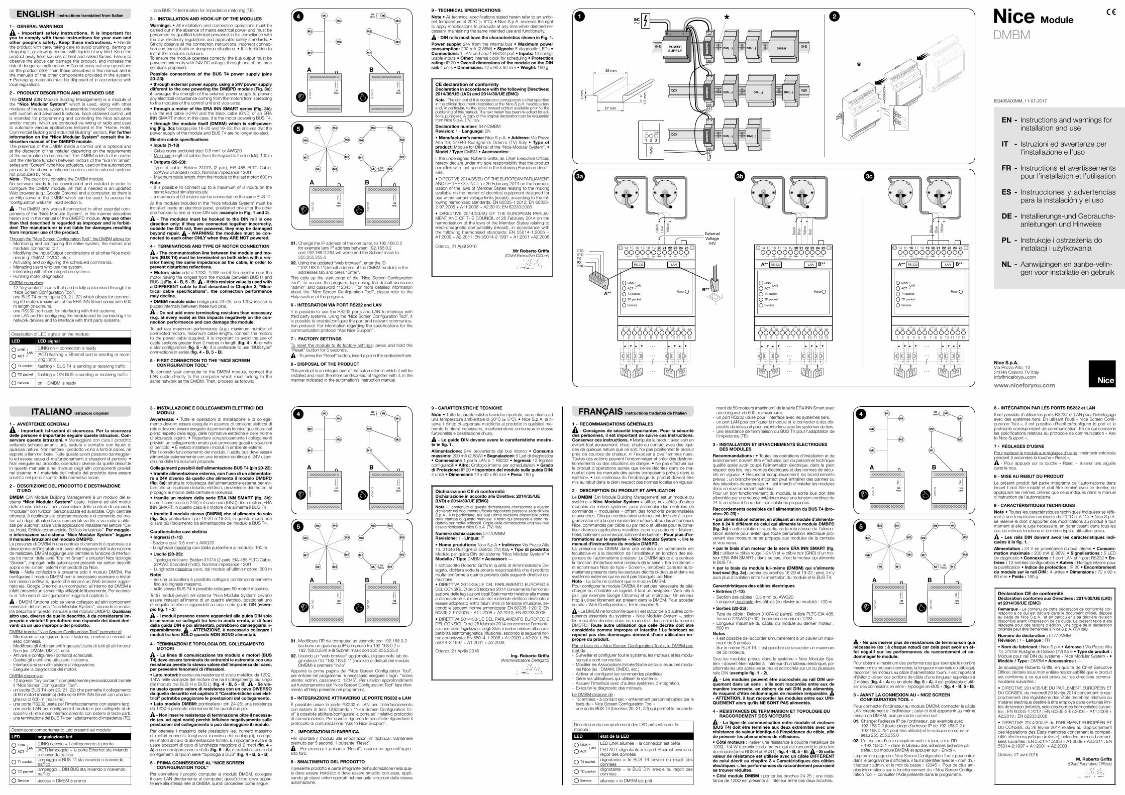
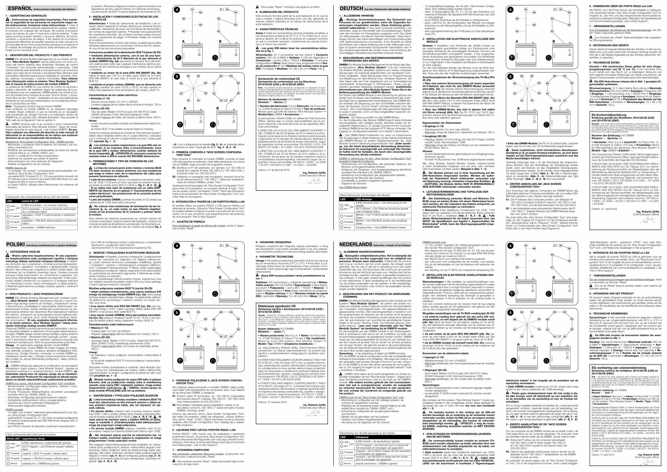
- The communication line between the module and mo-tors (BUS T4) must be terminated on both sides with a res-istor having the same impedance as the cable, in order to prevent disturbing reflections.• Motors side: adda120Ω,1/4Wmetal film resistornear themotor having the longest from the module (between BUS H and BUS L) (Fig. 4 - B, 5 - B). - If this resistor value is used with a DIFFERENT cable to that described in Chapter 3, “Elec-trical cable specifications”, the connection performance may decline.• DMBM module side:bridgepins24–25;one120Ωresistorisplaced internally between these two pins.
- Do not add more terminating resistors than necessary (e.g. at every node) as this impacts negatively on the con-nection performance and can damage the module.
To achieve maximum performance (e.g.: maximum number ofconnected motors, maximum cable length), connect the motors to the power cable supplied. It is important to avoid the use of cable sections greater than 2 metres in length (fig. 4 - A) or with a star configuration (fig. 5 - A);itispreferabletouse“BUStype”connections in series (fig. 4 - B, 5 - B).
5 - FIRST CONNECTION TO THE “NICE SCREEN CONFIGURATION TOOL”
To connect your computer to the DMBM module, connect the LAN cable directly to the computer which must belong to the samenetworkastheDMBM.Then,proceedasfollows:
9 - TECHNICAL SPECIFICATIONS
Note • All technical specifications stated herein refer to an ambi-enttemperatureof20°C(±5°C).•NiceS.p.A.reservestherightto apply modifications to products at any time when deemed ne-cessary, maintaining the same intended use and functionality.
- DIN rails must have the characteristics shown in Fig. 1.
Power supply: 24V from the internal bus • Maximum power consumption:200mA(2.88W)•Signals:5diagnosticLEDs•Connections:1LANportand1RS232port • Inputs: 12 config-urable Inputs • Other: Internal clock for scheduling • Protection rating: IP 20 • Overall dimensions of the module on the DIN rail: 4 units • Dimensions: 72 x 90 x 60 mm • Weight:180g
Mi
M4
M3
M2
M1
A
Mi
M7
M6
M4
M3
M2
M1
M5
120Ohm
120Ohm
120ohm
Mi
M7
M6
M4
M3
M2
M1
M5
A
120Ohm
B
120Ohm
Mi
M4
M3
M2
M1
120Ohm
120Ohm
B
5
Mi
M4
M3
M2
M1
A
Mi
M7
M6
M4
M3
M2
M1
M5
120Ohm
120Ohm
120ohm
Mi
M7
M6
M4
M3
M2
M1
M5
A
120Ohm
B
120Ohm
Mi
M4
M3
M2
M1
120Ohm
120Ohm
B
4
CE declaration of conformityDeclaration in accordance with the following Directives: 2014/35/UE (LVD) and 2014/30/UE (EMC)Note - ThecontentofthisdeclarationcorrespondstothatspecifiedintheofficialdocumentdepositedattheNiceS.p.A.headquartersand, in particular, to the latest revised edition available prior to the publishing of this manual. The text herein has been re-edited for ed-itorial purposes. A copy of the original declaration can be requested from Nice S.p.A. (TV) Italy.
Declaration number: 547/DMBMRevision: 1 - Language:EN
• Manufacturer’s name: Nice S.p.A. • Address: Via Pezza Alta 13, 31046Rustignè diOderzo (TV) Italy •Type of product: Module for DIN rail of the “Nice Modular System”. • Model / Type: DMBM • Accessories: ––
I,theundersignedRobertoGriffa,asChiefExecutiveOfficer,hereby declare under my sole responsibility that the product complieswiththatspecifiedinthefollowingEuropeandirect-ives:
•DIRECTIVE2014/35/EUOFTHEEUROPEANPARLIAMENTANDOFTHECOUNCILof26February2014ontheharmon-isation of the laws of Member States relating to the making available on the market of electrical equipment designed for use within certain voltage limits (recast), according to the fol-lowingharmonisedstandards:EN60335-1:2012;EN60335-2-97:2006+A11:2008+A2:2010;EN62233:2008
• DIRECTIVE 2014/30/EU OF THE EUROPEAN PARLIA-MENTANDOFTHECOUNCILof26February2014ontheharmonisation of the laws of the Member States relating to electromagnetic compatibility (recast), in accordance with the following harmonised standards: EN 55014-1:2006+A1:2009+A2:2011;EN55014-2:1997+A1:2001+A2:2008
Oderzo, 21 April 2016Mr Roberto Griffa
(Chief Executive Officer)
DescriptionofLEDsignalsonthemodule:
LED LED signal
LINK
ACT
T4 packet
TD packet
Service
LAN(LINK) on = connection is ready (ACT) flashing = Ethernetportissendingorrecei-ving traffic
LINK
ACT
T4 packet
TD packet
Service
LAN
flashing = BUS T4 is sending or receiving traffic
LINK
ACT
T4 packet
TD packet
Service
LAN
flashing = DIN BUS is sending or receiving traffic
LINK
ACT
T4 packet
TD packet
Service
LAN
on = DMBM is ready
DescriptionducomportementdesLEDprésentessurlemodule :
LED état de la LED
LINK
ACT
T4 packet
TD packet
Service
LANLEDLINKallumée=la connexion est prête LEDACTclignotante=leportEthernetenvoieoureçoitdesdonnées
LINK
ACT
T4 packet
TD packet
Service
LAN
clignotante = le BUS T4 envoie ou reçoit desdonnées
LINK
ACT
T4 packet
TD packet
Service
LAN
clignotante = le BUS DIN envoie ou reçoit desdonnées
LINK
ACT
T4 packet
TD packet
Service
LAN
allumée = le DMBM est prêt
Déclaration CE de conformitéDéclaration conforme aux Directives : 2014/35/UE (LVD) et 2014/30/UE (EMC)Remarque - Le contenu de cette déclaration de conformité cor-respondàcequiestdéclarédans ledocumentofficiel,déposéau siège de Nice S.p.A., et en particulier à sa dernière révision disponible avant l’impression de ce guide. Le présent texte a été réadapté pour des raisons d’édition. Une copie de la déclaration originale peut être demandée à Nice S.p.A. (TV) Italy.
Numéro de déclaration : 547/DMBMRévision : 1 - Langue :FR
• Nom du fabricant : Nice S.p.A • Adresse : Via Pezza Alta 13,31046RustignèdiOderzo(TV)Italie•Type de produit : ModulepourrailDINdusystème« NiceModularSystem » • Modèle / Type : DMBM • Accessoires : ––
JesoussignéRobertoGriffa,enqualitédeChiefExecutiveOfficer,déclaresousmonentièreresponsabilitéqueleproduitest conforme à ce qui est prévu par les directives commu-nautairessuivantes :
•DIRECTIVE2014/35/UEDUPARLEMENTEUROPÉENETDUCONSEILdumercredi26février2014concernantlerap-prochementdeslégislationsdesÉtatsmembresrelativesaumatériel électrique destiné à être employé dans certaines limi-tes de tension (refonte), selon les normes harmonisées suivan-tes :EN60335-1:2012;EN60335-2-97:2006+A11:2008+A2:2010;EN62233:2008
•DIRECTIVE2014/30/UEduPARLEMENTEUROPÉENETDUCONSEILdu26février2014relativeaurapprochementdeslégislationsdesÉtatsmembresconcernantlacompati-bilité électromagnétique (refonte), selon les normes harmoni-séessuivantes:EN55014-1:2006+A1:2009+A2:2011;EN55014-2:1997+A1:2001+A2:2008
Oderzo, 21 avril 2016M. Roberto Griffa
(Chief Executive Officer)
Mi
M4
M3
M2
M1
A
Mi
M7
M6
M4
M3
M2
M1
M5
120Ohm
120Ohm
120ohm
Mi
M7
M6
M4
M3
M2
M1
M5
A
120Ohm
B
120Ohm
Mi
M4
M3
M2
M1
120Ohm
120Ohm
B
5
Mi
M4
M3
M2
M1
A
Mi
M7
M6
M4
M3
M2
M1
M5
120Ohm
120Ohm
120ohm
Mi
M7
M6
M4
M3
M2
M1
M5
A
120Ohm
B
120Ohm
Mi
M4
M3
M2
M1
120Ohm
120Ohm
B
4
1 m
m
7,5
mm
35 mm
27 mm
DescrizionecomportamentoLedpresentisulmodulo:
LED segnalazione led
LINK
ACT
T4 packet
TD packet
Service
LAN(LINK) acceso = il collegamento è pronto(ACT)lampeggio=laportaEthernetstainviandoo ricevendo traffico
LINK
ACT
T4 packet
TD packet
Service
LAN
lampeggio = BUS T4 sta inviando o ricevendo traffico
LINK
ACT
T4 packet
TD packet
Service
LAN
lampeggio = DIN BUS sta inviando o ricevendo traffico
LINK
ACT
T4 packet
TD packet
Service
LAN
acceso = DMBM è pronto
Mi
M4
M3
M2
M1
A
Mi
M7
M6
M4
M3
M2
M1
M5
120Ohm
120Ohm
120ohm
Mi
M7
M6
M4
M3
M2
M1
M5
A
120Ohm
B
120Ohm
Mi
M4
M3
M2
M1
120Ohm
120Ohm
B
5
Mi
M4
M3
M2
M1
A
Mi
M7
M6
M4
M3
M2
M1
M5
120Ohm
120Ohm
120ohm
Mi
M7
M6
M4
M3
M2
M1
M5
A
120Ohm
B
120Ohm
Mi
M4
M3
M2
M1
120Ohm
120Ohm
B
4
Dichiarazione CE di conformitàDichiarazione in accordo alle Direttive: 2014/35/UE (LVD) e 2014/30/UE (EMC)Nota - Il contenuto di questa dichiarazione corrisponde a quanto dichiaratoneldocumentoufficialedepositatopressolasedediNiceS.p.A., e in particolare, alla sua ultima revisione disponibile prima della stampa di questo manuale. Il testo qui presente è stato ria-dattatopermotivieditoriali.Copiadelladichiarazioneoriginalepuòessere richiesta a Nice S.p.A. (TV) Italy.
Numero dichiarazione: 547/DMBMRevisione: 1 - Lingua: IT
• Nome produttore: Nice S.p.A • Indirizzo: Via Pezza Alta 13,31046RustignèdiOderzo(TV)Italy•Tipo di prodotto: Modulo per guida DIN del sistema “Nice Modular System” • Modello / Tipo: DMBM • Accessori: ––
IlsottoscrittoRobertoGriffainqualitàdiAmministratoreDe-legato, dichiara sotto la propria responsabilità che il prodotto risulta conforme a quanto previsto dalle seguenti direttive co-munitarie:•DIRETTIVA2014/35/UEDELPARLAMENTOEUROPEOEDELCONSIGLIOdel26febbraio2014concernentel’armoniz-zazione delle legislazioni degli Stati membri relative alla messa a disposizione sul mercato del materiale elettrico destinato a essere adoperato entro taluni limiti di tensione (rifusione), se-condoleseguentinormearmonizzate:EN60335-1:2012;EN60335-2-97:2006+A11:2008+A2:2010;EN62233:2008
•DIRETTIVA2014/30/UEDELPARLAMENTOEUROPEOEDELCONSIGLIOdel26febbraio2014concernentel’armoniz-zazione delle legislazioni degli Stati membri relative alla com-patibilità elettromagnetica (rifusione), secondo le seguenti nor-mearmonizzate:EN55014-1:2006+A1:2009+A2:2011;EN55014-2:1997+A1:2001+A2:2008
Oderzo, 21 Aprile 2016Ing. Roberto Griffa
(Amministratore Delegato)
ESPAÑOL Instrucciones traducidas del italiano
1 - ADVERTENCIAS GENERALES
- Instrucciones de seguridad importantes. Para mante-ner la seguridad de las personas es importante seguir es-tas instrucciones. Conservar estas instrucciones. • Tratar el producto con cuidado evitando aplastamientos, golpes, caídas o el contacto con cualquier tipo de líquido. No colocar el producto cerca de fuentes de calor ni exponerlo a llamas abiertas. Todas estas acciones pueden dañarlo y provocar defectos de funcio-namiento o situaciones de peligro. • No realizar en el producto operaciones diferentes de aquellas descritas en este manual y en los manuales de los otros componentes previstos en el sistema. • Elmaterialdelembalajedelproductodebeeliminarsedeconfor-midad con la normativa local.
2 - DESCRIPCIÓN DEL PRODUCTO Y USO PREVISTO
DMBM (Din Module Building Managemen) es un módulo del sis-tema “Nice Modular System” que se utiliza junto con otros mó-dulos del mismo sistema para ensamblar centrales de control “modulares” con funciones personalizadas y avanzadas. Cada central obtenida está destinada a la programación y al control por cable o por radio de los motores o actuadores Nice utilizados para automatizar diferentes aplicaciones instaladas en viviendas, hote-les, edificios comerciales y edificios industriales. Para obtener más información sobre el sistema “Nice Modular System”, leer el manual de instrucciones del módulo DMBPD.La presencia de DMBM en una central de control es opcional y queda a discreción del instalador según las exigencias de la au-tomatización que va a realizarse. DMBM añade a la central la fun-cióndeinterfazentremotoresdelaserie“EraInnSmart”yactua-dores Nice de tipo “Screen”, empleados en las automatizaciones existentes en los sectores mencionados y en los sistemas exterio-res no producidos por Nice.Nota-ElpaquetecontienesoloelmóduloDMBM.Para configurar el módulo DMBM no es necesario descargar o instalarningúnsoftware; loquesenecesitaesunnavegadorwebactualizado(ej.GoogleChrome)yunordenador;dentrodelDMBM hay un servidor Http utilizable libremente. Para acceder al “sitio web de configuración” leer el capítulo 5.
- DMBM funciona solo si se conecta a otros componentes esenciales del sistema “Nice Modular System”, según las moda-lidades descritas en este manual, y del módulo DMBPD. Se pro-híbe cualquier uso diferente del descrito en este manual. El fabricante no se responsabiliza de los daños que pudieran derivarse de un uso inadecuado del producto.
Mediante la “Nice Screen Configuration Tool”, DMBM permite:- Monitorizar y configurar todo el sistema, los motores y los mó-
dulos conectados a él.- Modificar las asociaciones entrada/salida de todos los demás
módulos Nice (p. ej., DMAM, DMDC, etc.).- Activar y configurar los mandos programados.- Gestionar los usuarios que utilizan el sistema.- Interconectarse con otros sistemas de integración.- Realizareldiagnósticodelosmotores.
DMBM dispone de:- 12 entradas “dry contact” completamente personalizables me-
diante la “Nice Screen Configuration Tool”.- una salida BUS T4 (pines 20, 21, 22) que permite la conexión de 50motores(comomáximo)delaserieERAINNSmartconunalongitud de 600 m (como máximo).
- unpuertoRS232utilizadoparainterconectarconsistemasdeterceros.
- un puerto LAN para configurar el módulo y para conectarlo a los dispositivos de red y para la interfaz con sistemas de terceros.
- unaterminacióndelBUST4paralaadaptacióndeimpedancia(TE).
3 - INSTALACIÓN Y CONEXIONES ELÉCTRICAS DE LOS MÓDULOS
Advertencias: • Todas las operaciones de instalación y de co-nexión deben realizarse sin tensión eléctrica por personal técnico cualificado, respetando las leyes, las normativas de electricidad y las normas de seguridad vigentes. • Respetarescrupulosamentelasconexionesprevistas:unaconexiónerróneapuedeprovocaraverías y situaciones de peligro. • Prohibido instalar los módulos en el exterior.Para el funcionamiento correcto del módulo, la salida bus se debe alimentar externamente con una tensión continua de 24V, utilizan-do una de las tres soluciones propuestas.
Conexiones posibles de la alimentación BUS T4 (pines 20-23):• mediante alimentación externa, con el uso de una fuen-te de alimentación de 24 V diferente de la que alimenta el módulo DMBPD (fig. 3a): aprovecha la robustez de la alimenta-ción externa para evitar que cualquier interferencia eléctrica pro-veniente de los motores se propague a los módulos de la central yviceversa;• mediante un motor de la serie ERA INN SMART (fig. 3b): utilizar el cable rojo (+24 V) y el cable negro (GND) de un motor ERA INNSMART; en este caso elmotor es el que alimenta elBUST4;• mediante el propio módulo (DMBM), que se alimenta solo (fig. 3c): puentear lospines16-20y19-23;deestamaneranohabrá más aislamiento entre alimentación del módulo y BUS T4.
Características de los cables eléctricos• Entradas (1-13)- Seccióndeloscables:0,5mm2 o AWG20- Longitud máximadeloscables(delaconsolaalmódulo):100m
• Salidas (20-23):- Tipodecable:Belden3107A(2-pair),EIA-485PLTCCable,22AWGStranded(7x30),Nominalimpedance120Ω
- Longitud máximadelcable,delmóduloalúltimomotor:600mNotas:- aunaconsolaesposibleconectarsimultáneamentehasta8en-
tradas.- al mismo BUS T4 es posible conectar hasta 50 motores.
Todos los módulos previstos en el sistema “Nice Modular System” deben estar instalados dentro de un cuadro eléctrico, colocados uno a continuación del otro y enganchados en una o varias guías DIN (ejemplo fig. 1 - 2).
- Los módulos pueden engancharse a la guía DIN solo en un sentido: si se conectan entre sí incorrectamente, fuera de la guía DIN y reciben alimentación, podrían dañarse de forma irreparable. - ATENCIÓN: Es necesario conectar los módulos entre sí SOLO cuando NO RECIBEN alimentación.
4 - TERMINACIONES Y TIPO DE CONEXIÓN DE LOS MOTORES
- La línea de comunicación entre módulo y motores (BUS T4) debe terminar en ambos extremos con una resistencia que tenga el mismo valor de la impedancia del cable para prevenir fenómenos de reflexión.• Lado de los motores: colocar una resistencia de estrato metá-licode120Ω1/4Wjuntoalmotorquetienelaconexiónmáslar-ga desde el módulo (entre BUS H y BUS L) (fig. 4 - B, 5 - B). - Si se utiliza este valor de resistencia con un cable DIFE-RENTE del descrito en el capítulo 3 “Características de los cables eléctricos”, las prestaciones de la conexión podrían verse perjudicadas.• Lado del módulo DMBM:puentearlospines24-25;existeunaresistenciade120Ωentreestosdospines.
- No colocar más resistencias de terminación de las ne-cesarias (p. ej., en cada nodo), ya que influirán negativa-mente en las prestaciones de la conexión y podrían dañar el módulo.
Para obtener las máximas prestaciones (ej. número máximo de motores conectados, longitud máxima del cableado), conectar los motores al cable de alimentación suministrado. Esimportante evi-tar utilizar trozos de cable de más de 2 metros de longitud (fig. 4
- A) o con configuración en estrella (fig. 5 - A);espreferibleutilizarconexiones en serie “topología de BUS” (fig. 4 - B, 5 - B).
5 - PRIMERA CONEXIÓN A “NICE SCREEN CONFIGURA-TION TOOL”
Para conectar el ordenador al módulo DMBM, conectar el cable LANdirectamentealordenador;éstedebeperteneceralamismareddeDMBM;luegoprocederdelasiguientemanera:01.Modificarel IPdelordenador,porejemplocon192.168.0.2
(puedesercualquierIPentre192.168.0.2y192.168.0.254),yla Subnet mask con 255.255.255.0
02. Utilizando un navegador web actualizado, introducir en la ba-rradedireccioneselID“192.168.0.1”(direcciónpredetermi-nada del módulo DMBM) y pulsar “Intro”.
Aparecerálaprimerapáginade“NiceScreenConfigurationTool”;para entrar en el programa, es necesario efectuar el login, “nom-bredeusuario:admin,contraseña:12345”.Paramásinformaciónsobre el funcionamiento de “Nice Screen Configuration Tool” con-sultar Help en el programa.
6 - INTEGRACIÓN A TRAVÉS DE LOS PUERTOS RS232 y LAN
Esposibleutilizar lospuertosRS232yLANpara la interfazconsistemas de terceros. Utilizando “Nice Screen Configuration Tool” es posible habilitar/configurar el puerto y el protocolo de comuni-cación.Enloqueconciernealasespecificacionesdelprotocolode comunicación “Ask to Nice Support”.
7 - AJUSTES DE FÁBRICA
Para restablecer el ajuste de fábrica del módulo:pulsar5segun-doslatecla“Reset”.
DEUTSCH Aus dem Italienischen übersetzte Anleitung
1 - ALLGEMEINE HINWEISE
- Wichtige Sicherheitshinweise. Die Sicherheit von Personen ist nur gewährleistet, wenn die folgenden An-weisungen eingehalten werden. Diese Anleitung gewis-senhaft aufbewahren. • Das Gerät vorsichtig handhaben und verhindern, dass es herunterfällt oder Druckbelastungen, Stößen oder dem Kontakt mit Flüssigkeiten ausgesetzt wird. Das Gerät von Wärmequellen und offenen Flammen fernhalten. Diese Hand-lungen können das Gerät beschädigen und Funktionsstörungen oderGefahrensituationenverursachen.•NurEingriffeamGerätdurchführen, die in dieser Anleitung oder in den Anleitungen sons-tiger im System verwendeter Komponenten beschrieben sind. • DasVerpackungsmaterialdesGerätsmussunterEinhaltungdereinschlägigen Umweltschutzvorschriften entsorgt werden.
2 - BESCHREIBUNG UND BESTIMMUNGSGEMÄSSE VERWENDUNG DES GERÄTS
DMBM (Din Module Building Managemen) ist ein Modul des Steu-erungssystems „Nice Modular System“ und wird zusammen mit anderen Modulen desselben Systems zum Aufbau modularer Steuerungen mit individuell abgestimmten und erweiterten Funk-tionen eingesetzt.. Diese Steuerungen sind zur Programmierung und Bedienung von Nice-Motoren bzw. Antrieben bestimmt, die über Kabel oder per Funk angesteuert und zur Automatisierung verschiedener Anwendungen in Wohnhäusern, Hotels und ge-werblich genutzten Gebäuden eingesetzt werden. Ausführliche Informationen zum „Nice Modular System“ finden Sie in der Bedienungsanleitung des DMBPD-Moduls.DerEinbaudesDMBM-ModulsineineSteuerungistoptionalunderfolgtnachErmessendesInstallateursentsprechenddenAnfor-derungen der zu realisierenden Automatisierung. Das DMBM-Mo-dul erweitert die Steuerung um eine Schnittstelle zwischen Mo-torenderBaureihe„EraInnSmart“undNice-AntriebenvomTyp„Screen“, die in Automatisierungen der oben genannten Segmen-te sowie in externen, nicht von Nice hergestellten Systemen ein-gesetzt werden.Hinweis - Die Packung enthält nur das DMBM-Modul.Für die Konfiguration des Moduls DMBM braucht keine Software heruntergeladen oder installiert werden. Benötigt werden ein ak-tualisierterWebbrowser(z.B.GoogleChrome)undeinComputer;im Modul DMBM ist ein frei nutzbarer HTTP-Server vorhanden. Der Zugang zur „Konfigurationswebsite“ ist in Kapitel 5 beschrieben.
- Das DMBD-Modul funktioniert nur, wenn es entsprechend den Anweisungen in dieser Anleitung und der Gebrauchsanleitung des DMBPD-Moduls an andere Hauptkomponenten der „Nice Modular System“-Steuerung angeschlossen wird. Jeder sonsti-ge, von der hierin beschriebenen Verwendung abweichen-de Gebrauch ist unsachgemäß und untersagt! Der Herstel-ler haftet nicht für Schäden, die durch eine unsachgemäße Verwendung des Geräts entstehen.
DMBM in Verbindung mit dem „Nice Screen Configuration Tool“ ermöglicht folgende Funktionen:- Überwachung und Konfiguration des gesamten Systems, der
Motoren und angeschlossenen Module.- Änderungder Eingangs- undAusgangsbelegung sämtlicher
sonstiger Nice-Module (z.B. DMAM, DMDC).- Aktivierung und Konfiguration der zeitgesteuerten Befehle.- Verwaltung der Benutzer des Systems.- Schnittstelle zu anderen integrierten Systemen.- Diagnose der Motoren.
Das DMBM-Modul bietet:
- 12potenzialfreieEingänge,diemitdem„NiceScreenConfigu-ration Tool“ beliebig belegt werden können.
- einen T4-Busausgang (Pin 20, 21, 22) für den Anschluss von maximal50MotorenderBaureiheERAINNSmartbeimax.600m Leitungslänge.
- einenRS232-AnschlussalsSchnittstellezuDrittsystemen.- einen LAN-Port für die Konfiguration des Moduls und dessen
Anschluss an die Netzwerkgeräte und als Schnittstelle zu Dritt-systemen.
- eine Leitungsterminierung des T4-Busses zur Impe-danzanpas-sung(TE).
3 - INSTALLATION UND ELEKTRISCHE ANSCHLÜSSE DER MODULE
Hinweis: • Installation und Anschluss der Geräte müssen an der spannungslos geschalteten Anlage von Fachpersonal unter strengsterEinhaltungdereinschlägigenRichtlinien,NormenundSicherheitsvorschriften durchgeführt werden. • Die vorgeschrie-benenAnschlüssesindgenauestenseinzuhalten;EinfehlerhafterAnschluss kann technische Störungen oder eine Gefahrensituati-on zur Folge haben. • Die Installation der Module im Außenbereich ist nicht zulässig.Für den störungsfreien Betrieb des Moduls muss der BUS-Aus-gang an eine externe 24-V-Gleichspannung angeschlossen wer-den. Dazu eine der drei möglichen Ausführungen verwenden.
Anschlussoptionen der Stromversorgung des T4-Bus (Pin 20-23):• Über eine externe Stromversorgung mit einem separaten 24-V-Netzteil, das nicht für das DMBPD-Modul verwendet wird (Abb. 3a): Die robuste externe Stromversorgung verhindert jegliche durch die Motoren verursachte elektrische Störung, die sich in die Module der Steuerung oder die Motoren übertragen könnte.• Über einen Motor der Baureihe ERA INN SMART (Abb. 3b): Mit dem roten Kabel (+24 V) und schwarzen Kabel (GND) eines ERAINNSMARTMotors.IndiesemFallübernimmtderMotordieStromversorgung des T4-Busses.• Über das DMBM-Modul, das sich in diesem Fall selbst mit Strom versorgt (Abb. 3c): Die Pin 16-20 und 19-23 über-brücken;danachsinddieStromversorgungenvonModulundT4-Bus nicht mehr elektrisch getrennt.
Eigenschaften der Elektrokabel• Eingänge (1-13)- Kabelquerschnitt:0,5mm2 oder AWG20- MaximaleLängederKabel(vomTastenfeldzumModul):100m
• Ausgänge (20-23):- Kabeltyp:Belden3107A(2-litzig),EIA-485PLTCKabel,22AWGverdrillt(7x30),Nennimpedanz120Ω
- Maximale Länge des Kabels vom Modul zum am weitesten ent-ferntenMotor:600m
Hinweis:- AneineBedientafelkönnengleichzeitigbiszu8Eingängeange-
schlossen werden.- An einen T4-Bus können max. 50 Motoren angeschlossen werden.
Alle „Nice Modular System“-Module müssen nebenei-nander in einen Schaltkasten eingebaut und auf einer oder mehreren DIN-Hutschienen montiert werden (Beispiel in Abb. 1 - 2).
- Die Module können nur in einer Ausrichtung auf der DIN-Hutschiene eingerastet werden. Werden sie außer-halb der Hutschiene falsch miteinander verbunden und mit Spannung versorgt, entstehen irreparable Schäden. - ACHTUNG, die Module dürfen NUR IN SPANNUNGSLO-SEM ZUSTAND miteinander verbunden werden.
4 - LEITUNGSTERMINIERUNG UND TOPOLOGIE DER MOTORANSCHLÜSSE
- Die Datenleitung zwischen Modul und Motoren (T4-BUS) muss an beiden Enden mit einem Widerstand termi-niert werden, der der Impedanz des Kabels entspricht, um elektrische Rückwirkungen zu verhindern.• Motorseite: EinenMetallschic htwiderstandmit 120Ω, 1/4Wneben dem am weitesten vom Modul entfernten Motor zwischen BUS H und BUS L installieren (Abb. 4 - B, 5 - B). - Falls dieser Widerstandswert für ein Kabel verwendet wird, das NICHT die Spezifikation aus Kapitel 3 „Eigenschaften der Elektrokabel“ erfüllt, kann die Übertragungsqualität einge-schränkt sein.
• Seite des DMBM-Moduls:DiePin24-25überbrücken;zwischendiesenzweiPinistinternein120-ΩWiderstandangeschlossen.
- Keine zusätzlichen, nicht erforderlichen Abschlusswi-derstände (z. B. an jedem Knoten) installieren, da sich diese negativ auf die Übertragungsleistungen auswirken und das Modul beschädigen können.
Optimale Leistungen (wie z. B. die Höchstzahl der angeschlos-senen Motoren oder die Höchstlänge der Verkabelung) werden erzielt, wenn die Motoren an das mitgelieferte Versorgungska-bel angeschlossen werden. Es ist wichtig, keine Kabelabschnitte mit einer Länge über 2 Meter (Abb. 4 - A) oder in Sternkonfigu-ration zu verwenden (Abb. 5 - A);ReihenschaltungendesTyps„BUS-Topologie“ (Abb. 4 - B, 5 - B) sind vorzuziehen.
5 - ERSTER ANSCHLUSS AM „NICE SCREEN CONFIGURATION TOOL“
Zum Anschluss des eigenen Computers am DMBM-Modul das LAN-Kabel direkt am Computer anschließen, der zum selben DM-BM-Netzgehörenmuss.Danachwiefolgtverfahren:01. Die IP-Adresse des Computers ändern, zum Beispiel mit
192.168.0.2(möglichistjedeIPzwischen192.168.0.2und192.168.0.254),unddieSubnetzmaskemit255.255.255.0
02. In die Adressleiste eines aktualisierten Webbrowsers die ID „192.168.0.1“(Default-AdressedesDMBM-Moduls)einge-benund„Enter“drücken.
Die erste Seite des „Nice Screen Configuration Tool“ wird ange-zeigt;fürdenZuganginsProgrammistdieAnmeldungerforder-lich,„Benutzername:admin,Passwort:12345“.WeitereInforma-tionen zur Funktionsweise des „Nice Screen Configuration Tool“ finden sich in der Help-Funktion des Programms.
POLSKI Instrukcja przetłumaczona z języka włoskiego
1 - OSTRZEŻENIA OGÓLNE
- Ważne zalecenia bezpieczeństwa. W celu zapewnie-nia bezpieczeństwa osób, postępować zgodnie z niniejszą instrukcją. Należy zachować niniejszą instrukcję. • Delikat-nieobchodzićsięz urządzeniem,chroniącjeprzedzgnieceniem,uderzeniami, upadkiem i kontaktemz jakiegokolwiek rodzajupłynami.Nieumieszczaćurządzeniawpobliżuźródełciepłai niewystawiaćgonadziałanieotwartegoognia.Opisanepowyżejsytuacjemogądoprowadzićdouszkodzeniaurządzenia,byćprzyczynąnieprawidłowegodziałanialubzagrożeń.•Niewyko-nywaćdziałańodmiennychodopisanychwniniejszejinstrukcjii winstrukcjachinnychczęściwchodzącychw składsystemu.•Materiałopakowaniowypodlegautylizacjizgodniez lokalnymiprzepisami.
2 - OPIS PRODUKTU I JEGO PRZEZNACZENIE
DMBM(DinModuleBuildingManagement)jestmodułemsyste-mu „Nice Modular System”stosowanymłączniez innymimo-dułamitegosamegosystemudomontażu„modułowych”centra-listerowniczych,posiadającychindywidualniedostosowaneiza-awansowanefunkcje.Każdacentralajestprzeznaczonadopro-gramowaniasilnikówi/lubsiłownikówNicesterowanychkablowolubradiowo,używanychdoautomatyzacjiróżnychaplikacjizain-stalowanych w sektorze „Dom, Hotel, Budynek handlowy, Budy-nekprzemysłowy”.W celu uzyskania dodatkowych informa-cji na temat systemu „Nice Modular System” należy prze-czytać instrukcję obsługi modułu DMBPD.ObecnośćDMBMwcentralisterowniczejjestopcjonalna,ojejuży-ciudecydujeinstalatorwzależnościodwymogówrealizowanejau-tomatyki.DMBMdodajecentralifunkcjęinterfejsumiędzysilnikamiserii„EraInnSmart”i siłownikamiNicetypologia„Screen”,używa-nymiwautomatyceobecnejw sektorachopisanychpowyżejorazsystemachzewnętrznych,któreniesąprodukowaneprzezNice.Uwaga-WopakowaniuznajdujesiętylkomodułDMBM.AbyskonfigurowaćmodułDMBMnietrzebaściągaćaniinstalo-wać żadnegoprogramu,wystarczy aktualnaprzeglądarka inter-netowa (np.GoogleChrome) ikomputer;wmoduleDMBMza-instalowanoserwerHttp,zktóregomożnaswobodniekorzystać.Abyprzejśćna„stronęinternetowąkonfiguracji”,należyprzeczy-taćrozdział5.
-DMBMfunkcjonujewyłączniepopodłączeniudopozostałychniezbędnychczęści systemu „NiceModularSystem”, zgodniezesposobamiopisanymiwniniejszejinstrukcjii moduleDMBPD.Ja-kiekolwiek użycie inne niż opisane uznaje się za niewłaści-we i zabronione! Producent nie odpowiada za szkody wyrzą-dzone na skutek nieprawidłowego użytkowania produktu.
DMBMprzyużyciu„NiceScreenConfigurationTool”umożliwia:- Monitorowaniei konfiguracjęcałegosystemu,silnikówi modu-łówdoniegopodłączonych.
- Zmianę Przypisania Wejścia/Wyjścia wszystkich pozostałychmodułówNice(np.DMAM,DMDC,itp.).
- Aktywacjęi konfiguracjęzaprogramowanychpoleceń.- Zarządzanieużytkownikami,którzyużywająsystemu.- Łączeniesięz innymisystemamiintegrującymi.- Wykonywanie diagnostyki silników.
DMBM posiada:- 12wejść„drycontact”całkowiciepersonalizowanychprzyuży-
ciu „Nice Screen Configuration Tool”.- wyjścieBUST4(zacisk20,21,22),któreumożliwiapodłączenie50silników(maksymalnie)seriiERAINNSmartdługości600m(maksymalnie).
- portRS232używanydołączeniaz systemamizewnętrznymi.
- portLANdokonfiguracjimodułuipołączeniagozurządzeniamisieciowymi i z systemami stron trzecich.
- zakończenieBUST4dodopasowaniaimpedancji(TE).
3 - MONTAŻ I PODŁĄCZENIA ELEKTRYCZNE MODUŁÓW
Ostrzeżenia: • Wszelkieczynnościinstalacyjneipodłączeniowemuszą być wykonane po odłączeniu od napięcia elektryczne-go, przez personel techniczny posiadający kwalifikacje zgodnez przepisami i zgodnie z obowiązującymi przepisami elektrycz-nymi iprzepisamibezpieczeństwa.•Należyściśleprzestrzegaćprzewidzianychpodłączeń:błędnepołączeniemożedoprowadzićdouszkodzenialubstworzeniazagrożenia.•Zabraniasięinstalo-waniamodułównazewnątrz.Wceluprawidłowegofunkcjonowaniamodułu,wyjściebusmusibyćzasilanezewnętrznieprądemstałym24V,przyużyciujednegoztrzechzaproponowanychrozwiązań.
Możliwe połączenia zasilania BUS T4 (zacisk 20-23):• dzięki zasilaniu zewnętrznemu, przy użyciu zasilacza 24V innego od zasilającego moduł DMBPD (rys. 3a): wykorzystuje budowęzasilaniazewnętrznegounikając,byjakiekolwiekzakłóce-nieelektryczne,pochodzącez silników,przeszłonamodułycen-trali i vice versa.• przy użyciu silnika serii ERA INN SMART (rys. 3b): użyćka-bla czerwonego (+24V) ikablaczarnego (GND)silnikaERA INNSMART;wtejsytuacjisilnikzasilaBUST4.• przy użyciu modułu (DMBM), który jest zasilany samodziel-nie (rys. 3c): połączyćmostkiemzacisk16-20i 19-23;w ten spo-sóbniebędzieizolacjimiędzyzasilaniemmodułuiBUST4.
Charakterystyka kabli elektrycznych• Wejścia (1-13)- Przekrójkabli:0,5mm2 lub AWG20- Długośćmaksymalnakabli(odklawiaturydomodułu):100m• Wyjścia (20-23):- Typologiakabla:Belden3107A(2pary),KabelEIA-485PLTC,Splot22AWG(7x30),Impedancjaznamionowa120Ω
- Długośćmaksymalnakabla,odmodułudoostatniegosilnika:600 m
Uwagi:- do klawiaturymożnapodłączyć równocześniemaksymalnie 8Wejść.
-dotejsamejmagistraliBUST4możnapodłączyćmaksymalnie50 silników.
Wszystkiemodułyprzewidzianewsystemie„NiceModularSys-tem”musząbyć zainstalowanewewnętrzu tablicyelektrycznej,ustawionejedenzadrugimipodłączonedojednejlubkilkuszynDIN (przykład rys. 1 - 2).
- Moduły można podłączyć do szyny DIN tylko w jednym kierunku: jeśli są podłączone między sobą w niewłaściwy sposób, poza szyną DIN i następnie zasilane, mogą zostać bezpowrotnie uszkodzone. - UWAGA, można łączyć ze sobą moduły WYŁĄCZNIE jeśli nie są zasilane.
4 - ZAKOŃCZENIA I TYPOLOGIA POŁĄCZEŃ SILNIKÓW
- Linia komunikacji między modułem i silnikami (BUS T4) musi być zakończona na obu końcach oporem o takiej sa-mej wartości impedancji kabla, aby nie dopuścić do zja-wisk odbicia.• Po stronie silnika:umieścićopórwpostaciwarstwymetalo-wej120Ω,1/4Wwpobliżusilnika,któryposiadapołączeniedłuż-szeodmodułu(międzyBUSHiBUSL)(rys. 4 - B, 5 - B). - W razie użycia tej wartości oporu z kablem INNYM od opisa-nego w rozdziale 3 „Charakterystyka kabli elektrycznych” mogą się pogorszyć osiągi połączenia.• Po stronie modułu DMBM:połączyćmostkiemstyki24-25;wewnętrzumiędzytymidwomastykamijestobecnyopór120Ω.
- Nie stosować więcej oporów na zakończeniu (np. na każdym węźle), ponieważ wpływa to negatywnie na osiągi połączeniowe i może uszkodzić moduł.
Abyosiągnąćmaksymalnąwydajność(podwzględemnp.maksy-malnej liczbypodłączonychsilników,maksymalnejdługościoka-blowania),należypodłączyćsilnikidodostarczonegokablazasi-lającego.Nie należystosowaćodcinkówkablaprzekraczającychdługość2metrów(rys. 4 - A) ani konfiguracji gwiazdy (rys. 5 - A);zalecasięstosowaniepołączeńtypuszeregowego„topologiama-gistrali” (rys. 4 - B, 5 - B).
5 - PIERWSZE POŁĄCZENIE Z „NICE SCREEN CONFIGU-RATION TOOL”
AbypołączyćwłasnykomputerzmodułemDMBM,należypodłą-czyćkabelLANbezpośredniodokomputera,którymusinależećdotejsamejsieciDMBM,anastępnie:01.Zmienić adres IP komputera, np. 192.168.0.2 (odpowiedni
jestdowolnyadresIPzzakresu192.168.0.2-192.168.0.254)orazmaskępodsiecina255.255.255.0
02.Korzystajączaktualnejwersjiprzeglądarki,wpisaćwpa-sekadresunumerID„192.168.0.1”(adresdomyślnymodułuDMBM)inacisnąć„enter”.
Otworzy się pierwsza strona „Nice Screen Configuration Tool”;abywejśćdoprogramu,należysięzalogować,„nazwaużytkow-nika:admin,hasło:12345”.Dalszeinformacjenatematsposobudziałania„NiceScreenConfigurationTool”znajdująsięwzakład-ce Help programu.
6 - ŁĄCZENIE PRZY UŻYCIU PORTÓW RS232 i LAN
Portów RS232 i LAN można użyć do połączenia z systemamipodmiotówtrzecich.Zapomocą„NiceScreenConfigurationTool”możnaaktywować/skonfigurowaćportorazjegoprotokółkomu-nikacyjny.Informacjenatematspecyfikacjidotyczącychprotokołukomunikacyjnego:„AsktoNiceSupport”.
7 - USTAWIENIA FABRYCZNE
Abyprzywrócić ustawienia fabrycznemodułu: przytrzymaćwci-śniętyprzez5sekundprzycisk„Reset”.
-Abynacisnąćprzycisk„Reset”,należywprowadzićigłęwprze-znaczony do tego otwór.
NEDERLANDS Instructies, vertaald uit het Italiaans
1 - ALGEMENE WAARSCHUWINGEN
- Belangrijke veiligheidsinstructies. Het is belangrijk dat deze instructies worden opgevolgd voor de veiligheid van personen. Bewaar deze instructies. • Behandel het product met zorg en voorkom dat het wordt geplet, dat ertegen wordt gestoten, dat het valt of dat het in aanraking komt met welke vloeistoffen dan ook. Zet het product niet in de buurt van warmte-bronnen en stel het niet bloot aan open vuur. Hierdoor kan het be-schadigd worden, waardoor storingen of gevaarlijke situaties kun-nen ontstaan. • Voer geen andere handelingen aan het product uit dan beschreven in deze handleiding en in de handleidingen van de andere onderdelen van het systeem. • Het verpakkings-materiaal van het product moet conform de plaatselijke verorde-ningen worden afgedankt.
2 - BESCHRIJVING VAN HET PRODUCT EN GEBRUIKSBE-STEMMING
DMBM (Din Module Building Management) is een module van het systeem “Nice Modular System”, die samen met andere mo-dules van hetzelfde systeem gebruikt wordt voor het assembleren van “modulaire” besturingseenheden met gepersonaliseerde en geavanceerde functies.Elkebesturingseenheid isbestemdvoorhet programmeren en besturen van de motoren en/of actuators van Nice, die via kabels of draadloos worden bestuurd en gebruikt voor het automatiseren van verschillende geïnstalleerde toepas-singen in de sector “Woning, Hotel, Commercieel gebouw, Indu-strieel gebouw”. Lees voor meer informatie over het “Nice Modular System” de handleiding bij de DMBPD-module.De aanwezigheid van een DMBM-module in een besturingseen-heid is optioneel en naar keuze van de installateur, op basis van de automatiseringseisen die gerealiseerd moeten worden. DMBM voegt aan de besturingseenheid de functie toe van interface tus-sendemotorenuitdeserie“EraInnSmart”endeNiceactuatorsvan het type “Screen” die gebruikt worden in de automatiseringen van de hierboven beschreven sectoren en in externe systemen die niet door Nice worden geproduceerd.Opmerking - In de verpakking zit alleen de DMBM-module. Om de DMBM module te configureren is het niet noodzakelijk een software te downloaden of te installeren. Het enige wat nodig is, is een geüpdate web browser (Google Chrome bv.) en een compu-ter. In de DMBM is al een http server aanwezig die vrij te gebrui-ken is. Om toegang te krijgen tot de “configuratie website” moet u hoofdstuk 5 doorlezen.
- DMBM werkt alleen als hij wordt aangesloten op andere es-sentiële onderdelen van het “Nice Modular System”, volgens de in deze handleiding beschreven modi en de modi van de DMBPD-module. Alle andere soorten gebruik die niet overeenstem-men met wat is voorgeschreven, worden als oneigenlijk en verboden beschouwd! De fabrikant is niet aansprake-lijk voor schade die voortkomt uit oneigenlijk gebruik van het product.
DMBM zorgt via het “Nice Screen Configuration Tool” voor:- Monitoring en configuratie van het volledige systeem, de
motoren en aangesloten modules.- Wijziging van de koppeling tussen Ingang/Uitgang van alle
andere Nice modules (bv. DMAM, DMDC, enz.).- Activering en configuratie van de geprogrammeerde
commando’s.- Beheer van de gebruikers van het systeem.- Interface met andere integratiesystemen.- Uitvoering van de diagnose van de motoren.
DMBM beschikt over:- 12 “dry contact” ingangen die volledig aangepast kunnen wor-
den via het “Nice Screen Configuration Tool”.- een uitgang van het type T4-BUS (pin 20, 21, 22) voor de aan-sluitingvanmaximum50motorenuitdeserieERAINNSmartmet een lengte van maximum 600 m.
- eenRS232-poortvoorinterfacemetexternesystemen.- een LAN-poort voor configuratie van de module, voor aanslui-
ting op de nettoestellen en voor de interface met systemen van derden.
- eenafsluitingvandeT4-BUSvoorimpedantie-aanpassing(TE).
3 - INSTALLATIE EN ELEKTRISCHE AANSLUITINGEN VAN DE MODULES
Waarschuwingen: • Alle installatie- en aansluithandelingen moe-ten worden uitgevoerd met de netvoeding uitgeschakeld en moeten worden uitgevoerd door b evoegd technisch personeel in overeen-stemming met de geldende wetgeving, elektrische voorschriften en veiligheidsnormen. • Houd u strikt aan de voorgeschreven aanslui-tingen: een verkeerde aansluiting kan storingen of gevaarlijke si-tuaties veroorzaken. • Het is verboden om de modules buiten te installeren.Voor een correcte werking van de module moet de bus-uitgang extern worden gevoed op 24V gelijkstroom met gebruik van één van de drie voorgestelde oplossingen.
Mogelijke aansluitingen van de T4-BUS-voeding (pin 20-23):• via externe voeding door gebruik van een extra 24V voe-dingseenheid, en niet degene die de DMBPD-module voedt (afb. 3a): benut de kracht van de externe voeding om te vermij-den dat elektrische storingen afkomstig van de motoren een ef-fect zouden hebben op de modules van de besturingseenheid en omgekeerd.• via een motor uit de serie ERA INN SMART (afb. 3b): ge-bruik de rode kabel (+24V) en de zwarte kabel (GND) van een motorERAINNSMART;inditgevalvoedtdemotordeT4-BUS.• via de DMBM-module die zichzelf voedt (afb. 3c): overbrug depinnen16-20en19-23;nuisdevoedingvandemoduleenvande T4-BUS niet meer geïsoleerd.
Kenmerken van de elektrische kabels
• Ingangen (1-13)- Kabeldoorsnede:0,5mm2 of AWG20- Maximalekabellengte(vanhetknoppenpaneelnaardemodule):
100 m
• Uitgangen (20-23):- Soortkabel:Belden3107A(2-pair),EIA-485PLTCCable,22AWGStranded(7x30),Nominalimpedance120Ω
- Maximalekabellengte,vandemodulenaardelaatstemotor:600 m
Opmerkingen:- opéénknoppenpaneelkunnenmaximaal8ingangentegelijk
worden aangesloten.- op eenzelfde T4-BUS kunnen maximaal 50 motoren worden
aangesloten.
Alle modules van het systeem “Nice Modular System” moeten ge-installeerd worden in een schakelkast, achter elkaar geplaatst en bevestigd aan een of meer DIN-rails (zie voor een voorbeeld afb. 1 - 2).
- De modules kunnen in één richting aan de DIN-rail worden bevestigd: als ze onderling op de verkeerde manier verbonden worden, buiten de DIN-rail en vervolgens worden aangesloten op de netvoeding, dan kunnen ze onherstel-baar beschadigd worden. - OPGELET: u mag de modu-les ENKEL onderling aansluiten wanneer ze NIET GEVOED WORDEN.
4 - AFSLUITINGEN EN VERBINDINGSMOGELIJKHEDEN VAN DE MOTOREN
- De communicatielijn tussen module en motoren (T4-BUS) moet worden afgesloten op beide uiteinden door een eindweerstand met dezelfde impedantie als de kabel, om reflectiefenomenen te vermijden.• Zijde motoren:plaatseenmetallischeweerstandvan120Ω,1/4W in de buurt van de motor die de langste aansluiting heeft (tussen BUS H en BUS L) (afb. 4 - B, 5 - B). - Indien deze weerstandswaarde wordt gebruikt met een kabel VERSCHIL-LEND van die beschreven in hoofdstuk 3 “Eigenschappen
elektrische kabels” is het mogelijk dat de prestaties van de aansluiting verminderen.• Zijde DMBM-module:overbrugpin24-25;tussendezetweepinneniseeninterneresistentievan120Ωaanwezig.
- Plaats geen eindweerstand waar dit niet nodig is (bv. bij elke knoop), want dit beïnvloedt op een negatieve wij-ze de prestaties van de aansluiting en kan de module be-schadigen.
Om zo hoog mogelijke prestaties te bereiken (bv. maximaal aantal aangesloten motoren, maximale lengte van de bekabeling), ver-bind u de motoren met bijgeleverde voedingskabel. Het is belang-rijk om geen stukken kabel te gebruiken die langer zijn dan 2 me-ter (afb. 4 - A) of met een stervormige configuratie (afb. 5 - A). We raden u aan seriekoppelingen te gebruiken (afb. 4 - B, 5 - B).
5 - EERSTE AANSLUITING OP DE “NICE SCREEN CONFIGURATION TOOL”
Om uw computer op de DMBM module aan te sluiten moet u de LAN kabel direct op uw computer aansluiten. De computer moet ophetzelfdenetwerkstaanalsdeDMBM.Gaalsvolgttewerk:01. Wijzig het IP adres van de computer, bijvoorbeeld
met192.168.0.2(elkIPadrestussen192.168.0.2en192.168.0.254isgoed)endeSubnetmaskmet255.255.255.0
02. Gebruik een geüpdate webbrowser, toets in de tab van de adressenhetID“192.168.0.1”(defaultadresvandeDMBMmodule) en druk op enter.
Nu verschijnt de eerste pagina van de “Nice Screen Configurati-onTool”.Ominhetprogrammatekomen,moetueerstinloggen:
-Parapulsar“Reset”,introducirunaagujaenelorificio.
8 - ELIMINACIÓN DEL PRODUCTO
Esteproducto formarápartede laautomatizaciónen lacualsevaya a instalar y deberá eliminarse junto con ella, aplicando los mismos criterios indicados en el manual de instrucciones de la automatización.
9 - CARACTERÍSTICAS TÉCNICAS
Notas • Todas las características técnicas indicadas se refieren a unatemperaturaambientede20°C(±5°C).•NiceS.p.A.sere-serva el derecho de modificar el producto en cualquier momento en que lo considere necesario, manteniendo las mismas funcio-nes y el mismo uso previsto.
- Las guías DIN deben tener las características indica-das en la fig. 1.
Alimentación: 24 V proveniente del bus interno • Consumo máximo:200mA (2.88W)•Señales:5LEDdediagnóstico•Conexiones:1puertoLANy1RS232 • Entradas: 12 entradas configurables • Otros: Relojinternoparaprogramaciones • Gra-do de protección: IP 20 • Medidas del módulo sobre la guía DIN: 4 unidades • Medidas: 72 x 90 x 60 mm • Peso:180g
8 - USUWANIE URZĄDZENIA
Niniejsze urządzenie jest integralną częścią automatyki, w którąjestwbudowaneimusizostaćusunięterazemz nią,przyzastoso-waniukryteriówpodanychw instrukcjiobsługizespołuautomatyki.
9 - PARAMETRY TECHNICZNE
Uwaga•Wszystkieprzestawioneparametrytechniczneodnosząsiędotemperaturyotoczenia20°C(±5°C).•FirmaNiceS.p.A.zastrzegasobieprawodowprowadzaniazmianproduktuw któ-rejkolwiekchwili,gwarantującjegofunkcjonalnośćiprzewidzianezastosowanie.
- Szyny DIN muszą posiadać cechy przedstawione na rys. 1.
Zasilanie:24Vpochodzącez magistraliwewnętrznej•Maksy-malne zużycie:200mA(2.88W)•Sygnalizacje: 5 Diod diagno-stycznych • Połączenia:1portLAN i1RS232 • Wejścia: 12 Wejśćkonfigurowalnych•Inne: Zegarwewnętrznydoprogramo-wania • Stopień ochrony: IP 20 • Wymiary modułu na szynie DIN: 4 jednostki • Wymiary: 72 x 90 x 60 mm • Masa:180g
“gebruikersnaam: admin - password: 12345”. Voor meer infor-matie betreffende de werking van de “Nice Screen Configuration Tool” kunt u de Helpfunctie raadplegen in het programma.
6 - INTEGRATIE VIA DE POORTEN RS232 en LAN
HetismogelijkdepoortenRS232enLANtegebruikenvoordeinterface met systemen van derden. M.b.v. de “Nice Screen Confi-guration Tool” is het mogelijk de poort en het betreffende commu-nicatieprotocol in te schakelen of te configureren. V.w.b. de spe-cificaties betreffende het communicatieprotocol raadpleegt u de “Ask to Nice Support”.
7 - FABRIEKSINSTELLINGEN
Om de module terug te brengen naar de fabrieksinstellingen:druktu5secondenopdeknop“Reset”.
-Omopde“Reset”knoptedrukkensteektueennaaldindespeciale opening.
8 - AFDANKING VAN HET PRODUCT
Dit product maakt integraal onderdeel uit van de automatisering waarin het geïnstalleerd moet worden, en moet hiermee samen worden afgedankt, met inachtneming van dezelfde criteria als die welke in de handleiding van de betreffende automatisering staan beschreven.
9 - TECHNISCHE KENMERKEN
Opmerkingen • Alle vermelde technische gegevens hebben betrekkingopeenomgevingstemperatuurvan20°C(±5°C).•Nice S.p.A. behoudt zich het recht voor om, op elk moment dat dit noodzakelijk wordt geacht, wijzigingen aan het product aan te brengen, waarbij hoe dan ook de gebruiksbestemming en de functionaliteit ervan gelijk blijven.
- De DIN-rails moeten de kenmerken hebben die weer-gegeven worden in afb. 1.
Voeding: 24V vanuit interne bus • Maximaal verbruik: 200 mA (2.88W) • Signaleringen: 5 diagnostische ledlampjes • Aan-sluitingen:1LAN-poorten1RS232 • Ingangen: 12 configu-reerbare ingangen • Overige: Interne klok voor planning • Be-schermingsgraad: IP 20 • Ruimte die de module inneemt op de DIN-rail: 4 eenheden • Afmetingen: 72 x 90 x 60 mm • Gewicht:180g
6 - EINBINDUNG ÜBER DIE PORTS RS232 und LAN
DieRS232undLANPortskönnenalsSchnittstellezuDrittsyste-men verwendet werden. Das „Nice Screen Configuration Tool“ er-möglicht es, den Port und das entsprechende Kommunikations-protokoll zu aktivieren/konfigurieren. Bezüglich der Spezifikationen zum Kommunikationsprotokoll „Ask to Nice Support“.
7 - WERKSEINSTELLUNGEN
Zum Zurücksetzen des Moduls auf die Werkseinstellungen:die„Re-set“-Taste 5 Sekunden gedrückt halten.
-ZumDrückender„Reset“-TasteeineNadelindievorgesehe-ne Öffnung einsetzen.
8 - ENTSORGUNG DES GERÄTS
Dieses Gerät ist integraler Bestandteil der Antriebs, in dem es ins-talliertwird,undmusszusammenmitdiesementsorgtwerden.Essind die in der Bedienungsanleitung des Antriebs genannten Vor-schriften zu beachten.
9 - TECHNISCHE DATEN
Hinweis • Alle technischen Daten gelten für eine Umge-bungstemperatur von 20 °C (±5 °C). • Der Hersteller Nice S.p.A.behältsichdasRechtvor,zubeliebigemZeitpunktundnacheigenemErmessenÄnderungenamGerätvorzunehmen,diedessenFunktionsweiseundEinsatzzwecknichtbeeinträchtigen.
- Die DIN-Hutschienen müssen die in Abb. 1 gezeigten Ei-genschaften aufweisen.
Stromversorgung: 24 V über interne Bus-Leitung • Maximale Stromaufnahme:200mA(2.88W)•Anzeigen:5Diagnose-LED• Eingänge:1LAN-Anschlussund1RS232-Port • Eingänge: 12konfigurierbareEingänge• Sonstiges: Interne Uhr für Zeitpro-gramme • Schutzart: IP 20 • Platzbedarf des Moduls auf der DIN-Hutschiene: 4 Einheiten •Abmessungen: 72 x 90 x 60 mm • Gewicht:180g
Declaración de conformidad CEDeclaración de conformidad con las Directivas: 2014/35/UE (LVD) y 2014/30/UE (EMC)Nota - Elcontenidodeestadeclaracióncorrespondealodeclaradoeneldo-cumentooficialdepositadoenlasededeNice S.p.A.y,enparticular,asuúltimarevisión disponible antes de la impresióndeestemanual.Eltextohasidoadap-tado por motivos de edición. No obstante, se puede solicitar una copia de la declaración original a Nice S.p.A. (TV) Italy.
Número de declaración: 547/DMBMRevisión: 1 - Idioma:ES
• Nombre del fabricante: S.p.A • Dirección: Via Pezza Alta 13,31046RustignèdiOderzo(TV)Italy•Tipo de producto: Módulo para guía DIN del sistema “Nice Modular System” • Modelo/tipo: DMBM • Accesorios: ––
Elquesuscribe,RobertoGriffa,encalidaddeChiefExecutiveOfficer,declarabajosupropia responsabilidadqueelpro-ducto responde a las prescripciones de las siguientes direc-tivascomunitarias:
•DIRECTIVA2014/35/UEDELPARLAMENTOEUROPEOYDELCONSEJOdel26defebrerode2014relativaalaarmo-nizacióndelasleyesdelosEstadosmiembrossobrelapuestaa disposición en el mercado de material eléctrico destinado a adoptarse dentro de los límites de tensión (refundición), según lassiguientesnormasarmonizadas:EN60335-1:2012;EN60335-2-97:2006+A11:2008+A2:2010;EN62233:2008
•DIRECTIVA2014/30/UEDELPARLAMENTOEUROPEOYDELCONSEJOdel26de febrerode2014relativaa laar-monizacióndelasleyesdelosEstadosmiembrossobrelacompatibilidad electromagnética (refundición) según las si-guientesnormasarmonizadas:EN55014-1:2006+A1:2009+A2:2011;EN55014-2:1997+A1:2001+A2:2008
Oderzo, 21 de abril de 2016Ing. Roberto Griffa
(Chief Executive Officer)
DescripcióndelcomportamientodelosLEDdelmódulo:
LED señal de LED
LINK
ACT
T4 packet
TD packet
Service
LAN(LINK) encendido = la conexión está lista (ACT)parpadeo=elpuertoEthernetestáenvian-do o recibiendo tráfico
LINK
ACT
T4 packet
TD packet
Service
LAN
parpadeo = BUS T4 está enviando o recibiendo tráfico
LINK
ACT
T4 packet
TD packet
Service
LAN
parpadeo = DIN BUS está enviando o recibiendo tráfico
LINK
ACT
T4 packet
TD packet
Service
LAN
encendido = DMBM está listo
Mi
M4
M3
M2
M1
A
Mi
M7
M6
M4
M3
M2
M1
M5
120Ohm
120Ohm
120ohm
Mi
M7
M6
M4
M3
M2
M1
M5
A
120Ohm
B
120Ohm
Mi
M4
M3
M2
M1
120Ohm
120Ohm
B
5
Mi
M4
M3
M2
M1
A
Mi
M7
M6
M4
M3
M2
M1
M5
120Ohm
120Ohm
120ohm
Mi
M7
M6
M4
M3
M2
M1
M5
A
120Ohm
B
120Ohm
Mi
M4
M3
M2
M1
120Ohm
120Ohm
B
4
EG-KonformitätserklärungErklärung gemäß den Richtlinien: 2014/35/UE (LVD) und 2014/30/UE (EMC)Hinweis - Der Inhalt dieser Konformitätserklärung entspricht den Angaben im offiziellenDokument,dasamFirmensitzderNiceS.p.A.aufbewahrtwird,indes-sen aktuellster Fassung vor der Drucklegung dieser Anleitung. Dieser Text wurde ausredaktionellenGründenangepasst.EineKopiederOriginalerklärungkannbeiNice S.p.A. (TV), Italien angefordert werden.
Nummer der Erklärung: 547/DMBMRevision: 1 - Sprache:DE
• Hersteller: Nice S.p.A • Anschrift: Via Pezza Alta 13, 31046RustignèdiOderzo(TV)Italy•Produkttyp: Modul für DIN-Hutschiene der Steuerung „Nice Modular System“ • Modell / Typ: DMBM • Zubehör: ––
DerUnterzeichnerRobertoGriffaerklärthiermiteigenverant-wortlichalsChiefExecutiveOfficer,dassdasProdukterfüllthi-nausdieVorschriftenderfolgendenEG-Richtlinien:
•RICHTLINIE2014/35/EUDESEUROPÄISCHENPARLA-MENTSUNDDESRATSvom26.Februar2014zurHarmo-nisierungderRechtsvorschriftenderMitgliedstaatenüberdieBereitstellung elektrischer Betriebsmittel zur Verwendung in-nerhalb bestimmter Spannungsgrenzen auf dem Markt (Neu-fassung), unter Anwendung folgender harmonisierter Nor-men:EN60335-1:2012;EN60335-2-97:2006+A11:2008+A2:2010;EN62233:2008
•RICHTLINIE2014/30/EUDESEUROPÄISCHENPARLA-MENTSUNDDESRATESvom26.Februar2014zurHar-monisierungderRechtsvorschriftenderMitgliedstaatenüberdie elektromagnetische Verträglichkeit (Neufassung), unter Anwendung folgenderharmonisierterNormen:EN55014-1:2006+A1:2009+A2:2011;EN55014-2:1997+A1:2001+A2:2008
Oderzo, 21. April 2016Ing. Roberto Griffa
(Chief Executive Officer)
BeschreibungderLed-AnzeigendesModuls:
LED LED-Anzeige
LINK
ACT
T4 packet
TD packet
Service
LAN
(LINK) Dauerleuchten = Die Verbindung ist her-gestellt(ACT) Blinken =DerEthernet-Anschlusssendetoder empfängt Daten
LINK
ACT
T4 packet
TD packet
Service
LAN
Blinken = Der T4-BUS sendet oder empfängt Daten
LINK
ACT
T4 packet
TD packet
Service
LAN
Blinken = Der DIN-BUS sendet oder empfängt Daten
LINK
ACT
T4 packet
TD packet
Service
LAN
Dauerleuchten = Das DMBM-Modul ist bereit
Mi
M4
M3
M2
M1
A
Mi
M7
M6
M4
M3
M2
M1
M5
120Ohm
120Ohm
120ohm
Mi
M7
M6
M4
M3
M2
M1
M5
A
120Ohm
B
120Ohm
Mi
M4
M3
M2
M1
120Ohm
120Ohm
B
5
Mi
M4
M3
M2
M1
A
Mi
M7
M6
M4
M3
M2
M1
M5
120Ohm
120Ohm
120ohm
Mi
M7
M6
M4
M3
M2
M1
M5
A
120Ohm
B
120Ohm
Mi
M4
M3
M2
M1
120Ohm
120Ohm
B
4
Deklaracja zgodności CEDeklaracja zgodna z Dyrektywami: 2014/35/UE (LVD) i 2014/30/UE (EMC)Uwaga - Zawartośćniniejszejdeklaracjizgodnościodpowiadaoświadcze-niomznajdującymsięwoficjalnymdokumenciezłożonymwsiedzibiefirmyNiceS.p.A.,wszczególnościostatnimzmianomdostępnymprzedwydru-kowaniemniniejszej instrukcji.Niniejszytekstzostałdostosowanywcelachwydawniczych.KopięoryginalnejdeklaracjimożnauzyskaćwsiedzibiespółkiNice S.p.A. (TV) Italy
Numer deklaracji: 547/DMBMWydanie: 1 - Język: PL
• Nazwa producenta: Nice S.p.A. • Adres: Via Pezza Alta 13,31046RustignèdiOderzo(TV)Italy•Typ urządzenia: Moduł do szynyDIN systemu „NiceModular System” • Model / Typ: DMBM • Urządzenia dodatkowe: ––
Ja,niżejpodpisanyRobertoGriffa,ChiefExecutiveOfficer,oświadczamnawłasnąodpowiedzialność,żeprodukt jestzgodnez postanowieniaminastępującychdyrektyweuro-pejskich:
•DYREKTYWAPARLAMENTUEUROPEJSKIEGOIRADYNR2014/35/UEzdnia26lutego2014rokuwsprawieharmoni-zacjiustawodawstwpaństwczłonkowskichodnoszącychsiędoudostępnianianarynkusprzętuelektrycznegoprzewidzia-negodostosowaniawokreślonychgranicachnapięcia(wer-sjaprzekształcona),zgodnieznastępującyminormamizhar-monizowanymi:EN60335-1:2012;EN60335-2-97:2006+A11:2008+A2:2010;EN62233:2008
•DYREKTYWAPARLAMENTUEUROPEJSKIEGO IRADY2014/30/UEz26lutego2014r.wsprawieharmonizacjiusta-wodawstwpaństwczłonkowskichwzakresiezgodnościelek-tromagnetycznej(wersjaprzekształcona),zgodnieznastępu-jącymi normami zharmonizowanymi: EN 55014-1:2006 +A1:2009+A2:2011;EN55014-2:1997+A1:2001+A2:2008
Oderzo, 21 kwietnia 2016inż. Roberto Griffa
(Chief Executive Officer)
Opiszachowaniadiodobecnychnamodule:
Dioda LED sygnalizacja diody
LINK
ACT
T4 packet
TD packet
Service
LAN(LINK)zaświecona=połączeniejestgotowe(ACT)miganie=portEthernetwysyłai odbieradane
LINK
ACT
T4 packet
TD packet
Service
LAN
miganie=BUST4wysyłai odbieradane
LINK
ACT
T4 packet
TD packet
Service
LAN
miganie=DINBUSwysyłai odbieradane
LINK
ACT
T4 packet
TD packet
Service
LAN
zaświecona=DMBMjestgotowy
Mi
M4
M3
M2
M1
A
Mi
M7
M6
M4
M3
M2
M1
M5
120Ohm
120Ohm
120ohm
Mi
M7
M6
M4
M3
M2
M1
M5
A
120Ohm
B
120Ohm
Mi
M4
M3
M2
M1
120Ohm
120Ohm
B
5
Mi
M4
M3
M2
M1
A
Mi
M7
M6
M4
M3
M2
M1
M5
120Ohm
120Ohm
120ohm
Mi
M7
M6
M4
M3
M2
M1
M5
A
120Ohm
B
120Ohm
Mi
M4
M3
M2
M1
120Ohm
120Ohm
B
4
EG-verklaring van overeenstemmingVerklaring conform de richtlijnen: 2014/35/UE (LVD) en 2014/30/UE (EMC)N.B. - De inhoud van deze verklaring stemt overeen met hetgeen verklaard is inhetofficiëledocumentdatisneergelegdbijdevestigingvanNiceS.p.A.,eninhetbijzondermetdelaatsterevisiehiervandievóórhetafdrukkenvandezehandleiding beschikbaar was. De onderhavige tekst is om redactionele redenen aangepast.EenkopievandeorigineleverklaringkanwordenaangevraagdbijNice S.p.A. (TV) Italy.
Nummer verklaring: 547/DMBMRevisie: 1 - Taal: NL
• Naam fabrikant: Nice S.p.A. • Adres: Via Pezza Alta 13, 31046 RustignèdiOderzo(TV)Italy•Producttype: Module voor DIN-rail van het systeem “Nice Modular System” • Model / Type: DMBM • Accessoires: ––
OndergetekendeRobertoGriffa,indienshoedanigheidvanChiefExecutiveOfficer,verklaartonderzijneigenverantwoordelijkheiddathet product in overeenstemming met de bepalingen van de volgen-decommunautairerichtlijnen:•RICHTLIJN2014/35/EUVANHETEUROPEESPARLEMENTENDERAADvanhetEuropeesParlementendeRaadvan26febru-ari 2014 betreffende de harmonisatie van de wetgevingen van de lidstaten inzake het op de markt aanbieden van elektrisch mate-riaal bestemd voor gebruik binnen bepaalde spanningsgrenzen (herschikking),volgensdevolgendegeharmoniseerdenormen:EN60335-1:2012;EN60335-2-97:2006+A11:2008+A2:2010;EN62233:2008•RICHTLIJN2014/30/EUVANHETEUROPEESPARLEMENTENDERAADvan26februari2014betreffendedeharmonisatievandewetgevingen van de lidstaten inzake elektromagnetische compa-tibiliteit (herschikking), op basis van de volgende geharmoniseer-denormen:EN55014-1:2006+A1:2009+A2:2011;EN55014-2:1997+A1:2001+A2:2008
Oderzo, 21 april 2016 Ing. Roberto Griffa(Chief Executive Officer)
Beschrijvingvandeledsaanwezigopdemodule:
LED ledsignaal
LINK
ACT
T4 packet
TD packet
Service
LAN(LINK) brandt = de aansluiting is gereed(ACT)knippert=deEthernet-poortisbezigmethet verzenden of ontvangen van gegevens
LINK
ACT
T4 packet
TD packet
Service
LAN
knippert = de T4-BUS is bezig met het verzenden of ontvangen van gegevens
LINK
ACT
T4 packet
TD packet
Service
LAN
knippert = de DIN-BUS is bezig met het verzen-den of ontvangen van gegevens
LINK
ACT
T4 packet
TD packet
Service
LAN
brandt permanent = DMBM is gereed
Mi
M4
M3
M2
M1
A
Mi
M7
M6
M4
M3
M2
M1
M5
120Ohm
120Ohm
120ohm
Mi
M7
M6
M4
M3
M2
M1
M5
A
120Ohm
B
120Ohm
Mi
M4
M3
M2
M1
120Ohm
120Ohm
B
5
Mi
M4
M3
M2
M1
A
Mi
M7
M6
M4
M3
M2
M1
M5
120Ohm
120Ohm
120ohm
Mi
M7
M6
M4
M3
M2
M1
M5
A
120Ohm
B
120Ohm
Mi
M4
M3
M2
M1
120Ohm
120Ohm
B
4
Related Documents