•JUKI Medium-sized Computer-controlled Cycle Machine ENGINEER'S MANUAL From the library of: Superior Sewing Machine & Supply LLC

Welcome message from author
This document is posted to help you gain knowledge. Please leave a comment to let me know what you think about it! Share it to your friends and learn new things together.
Transcript

•JUKI
Medium-sized Computer-controlled Cycle Machine
ENGINEER'S MANUAL
From the library of: Superior Sewing Machine & Supply LLC

PREFACE
This Engineer's Manual is written for the technical personnel who are responsible for the service and maintenanceof the machines.
The Instruction Manual for these machines intended for the maintenance personnel and operators at an apparelfactory contains detailed operating instructions. And this manual describes "How to Adjust", "Results of ImproperAdjustments", and other information which are not covered by the Instruction Manual.It is advis^le to use the pertinent Instruction Manual and Parts List together with this Engineer's Manual whencarrying <xit the maintenance of these machines.This manual mainly consist of three sections; the first section presents "Standard Adjustment", the second section,"How to Adjust", and the third, "Results of Improper Adjustment."
r
r
r
From the library of: Superior Sewing Machine & Supply LLC

CAUTION
X1. When a pattern change is made, or the bobbin
winder switch or the feeding frame switch isturned ON, feeding frame O comes downautomatically. So, never put your fingers underthe feeding frame. Be sure to keep your fingersaway from the feeding frame while the machine isin operation.
Be sure to turn the power switch OFF beforeremoving belt cover O and Y travel shaft cover
Do not operate the machine with the beltcover removed.
3. During operation, be careful not to allow your or any other person's head or hands to come close to thehandwheel, V belt or motor. Also, do not place anything near any of these parts while is in operation.Doing so may be dangerous.
4. Ifyour machine is equipped whit a belt cover, eye guard or any other protections, do not operate yourmachine with any of them removed.
From the library of: Superior Sewing Machine & Supply LLC
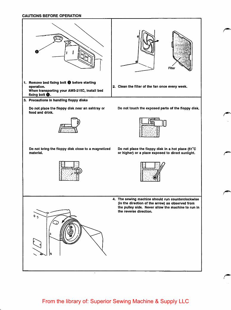
CAUTIONS BEFORE OPERATION
1. Remove bed fixing bolt O before startingoperation.When transporting your AMS-215C, Install bedfixing bolt 0>
3. Precautions in handling floppy disks
Do not place the floppy disk near an ashtray orfood and drink.
Do not bring the floppy disk close to a magnetizedmaterial.
=3;
12
RIter
2. Clean the filter of the fan once every week.
Do not touch the exposed parts of the floppy disk.
[13HI
CjD
Do not place the floppy disk In a hot place (51*0or higher) or a place exposed to direct sunlight.
4. The sewing machine should run counterclockwise(In the direction of the arrow) as observed fromthe pulley side. Never allow the machine to run Inthe reverse direction.
From the library of: Superior Sewing Machine & Supply LLC

5. Be sureto supply oil until the oil level reaches redmarks Q aic* 0 ®'' gauge. (When lubricatingthe bed, be sure move the feeding frame to the left.)
6. Before starting the machine which has been newiy set upor has not been usedfor a long period oftime,apply afew drops of thelubricating oil tothecrank assembly through hole O, one drop to racingsurface 0.
Be sure to load or unload floppy disk O while thepower is ON. if the power switch should beturned ON or OFF with the floppy disk mounted,the data stored in the disk may be destroyed.
8. TheAMS-215C is provided with the main unit input function as standard, however, a sewing patternwhich extends beyond the sewing area (180 mm x 110 mm) cannot besewnevenifinputting it.[When inputting data using the main unit input function, the travel limit ofthe sewing area cannot bedetected with accuracy.So, sometimes pattern data which is larger than the sewing area specified may be created.
From the library of: Superior Sewing Machine & Supply LLC

9. To raise the sewing machine, attach grip O supplied with the sewing machine and raise the sewingmachine in the direction of the arrow.
Be sure to use stopper 0 when working with the sewing machine raised.
%
XClosed
oi
1 f//(Don't Opem
Opened
10. When the threader and sewing machine areswitched ON, sew the desired sewing pattern withthe thread tension disk closed. Once you havecompleted the thread trimming, the thread tensiondisk will open.
11. When polyethylene oiler O becomes filled withoil, remove it and drain the oil.
12. Prior to operation, be sure to close the controlbox cover In order to prevent dust from gettinginto the control box. Dust into the control box
may lead to malfunctions or failures.
From the library of: Superior Sewing Machine & Supply LLC

CONTENTS
1. FEATURES 1
Z SPECIFICATIONS 3
3. OPERATION 6
3- 1. Names of the main components 63- 2. Control box panel 83- 3. Operation panel 103- 4. Other switches 123- 5. Checking before operation 133- 6. Operation procedure 143- 7. Precautions during operation 20
4. DESCRIPTION OF EACH MAIN COMPONENT 214-1. Sewing machine 214- 2. Control box 234- 3. Operation panel 254- 4. Motor 26
5. ADJUSTMENTS 275-1. Mechanical parts 275- 2. Electrical parts 15- 3. Rotary DIP switches for setting the test mode 121
6. FUNCTION 1276-1. How to set the memory switches 1276-2. Error messages 1656-3. Changing the settings on the panel displays 1666- 4. Thread breakage detecting function 1666-5. Temporary stop function 1666- 6. Function of setting thesecond origin 1676- 7. Travel limit detecting function 1676-8. Pattern enlarging/reducing function 1676- 9. Memory back-up function 1686-10. Max. sewing speed limit control knob 1686-11. Combining patterns 169
7. MAINTENANCE AND INSPECTION 1717-1. Cleaning the filter 1717- 2. Changing the direction of rotation of the sewing machine 1717-3. Replacing the fuse 1727-4. Adjustment and maintenance of the motors 1727-5. Replacing the printed circuit boards 1777- 6. How to measure the linevoltage 1797-7. AC input voltage tap ISl
8. TROUBLES AND CORRECTIVE MEASURES 1828- 1. Troubles and correaive measures (mechanical parts) 1828- 2. Troubles and corrective measures (electrical parts) 1898- 3. Troubles and corrective measures (Sewing conditions) 197
From the library of: Superior Sewing Machine & Supply LLC
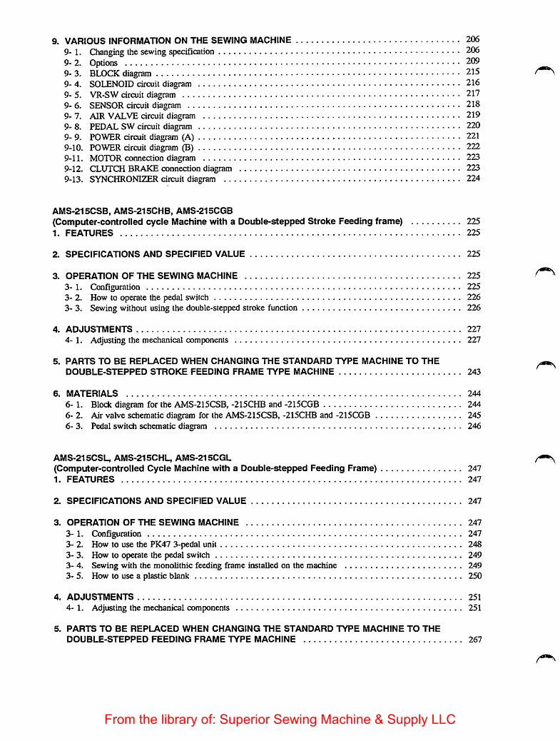
9. VARIOUS INFORMATION ON THE SEWING MACHINE 2069- 1. Changing the sewing specification 2069-2. Options 2099- 3. BLOCK diagram 2159- 4. SOLENOID circuit diagram 2169- 5. VR-SW circuit diagram 2179- 6. SENSOR circuit diagram 2189- 7. AIR VALVE circuit diagram 2199- 8. PEDAL SW circuit diagram 2209- 9. POWER circuit diagram (A) 2219-10. POWER circuit diagram (B) 2229-11. MOTOR conneaion diagram 2239-12. CLUTCH BRAKE connection diagram 2239-13. SYNCHRONIZER circuit diagram 224
AMS-215CSB, AMS-215CHB, AMS-215CGB(Computer-controlled cycle Machine with a Double-stepped Stroke Feeding frame) 2251. FEATURES 225
2. SPECIFICATIONS AND SPECIFIED VALUE 225
3. OPERATION OF THE SEWING MACHINE 225
3- 1. Configuration 2253- 2. How to operate the pedal switch 2263- 3. Sewing without using the double-stepped stroke function 226
4. ADJUSTMENTS 227
4-1. Adjusting the mechanical components 227
5. PARTS TO BE REPLACED WHEN CHANGING THE STANDARD TYPE MACHINE TO THE
DOUBLE-STEPPED STROKE FEEDING FRAME TYPE MACHINE 243
6. MATERIALS 244
6- 1. Block diagram for the AMS-215CSB, -215CHB and -215CGB 2446- 2. Air valve schematic diagram for the AMS-215CSB, -215CHB and -215CGB 2456- 3. Pedal switch schematic diagram 246
AMS-215CSL, AMS-215CHL, AMS-215CGL(Computer-controlled Cycle Machine with a Double-stepped Feeding Frame) 2471. FEATURES 247
2. SPECIFICATIONS AND SPECIFIED VALUE 247
3. OPERATION OF THE SEWING MACHINE 247
3- 1. Configuration 2473- 2. How to use the PK47 3-pedal unit 2483- 3. How to operate the pedal switch 2493- 4. Sewing with the monolithic feeding frame installed on the machine 2493- 5. How to use a plastic blank 250
4. ADJUSTMENTS 251
4-1, Adjusting the mechanical components 251
5. PARTS TO BE REPLACED WHEN CHANGING THE STANDARD TYPE MACHINE TO THE
DOUBLE-STEPPED FEEDING FRAME TYPE MACHINE 267
From the library of: Superior Sewing Machine & Supply LLC
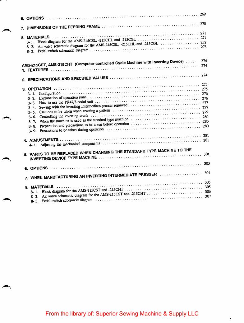
2696. OPTIONS
. . 270
7. dimensions OF THE FEEDING FRAME271
8. MATERIALS •• "' V 2718-1. Block diagram for the AMS-215CSU-215CI^an ' 2728-
8- 3. Pedal switch schematic diagram2.
AMS-215CST,AMS-215CHT (Computer-controlled Cycle Machine with Inverting Device) 2741. FEATURES
274
2. SPECIFICATIONS AND SPECIFIED VALUES275
3. OPERATION y.' 2753-1. Configuration 2763- 2. Explanation ofoperation panel 2763- 3. How to use the PK47/3-pedal unit ' 2773- 4. Sewing with the inverting intermediate presser removed3-5 Cautions tobe taken when creating a pattern 2793- 6. Controlling the inverting crank ' 2803- 7. When the machine is used as the standard type machine ^gQ3- 8. Preparation and precautions to be taken before operation y • ^go3. 9. Precautions to betaken during operation
281
4. ADJUSTMENTS '' " 2814-1. Adjusting the mechanical components
5. PARTS TO BE REPLACED WHEN CHANGING THE STANDARD TYPE MACHINE TO THEINVERTING DEVICE TVPE MACHINE
3036. OPTIONS
7. WHEN MANUFACTURING AN INVERTING INTERMEDIATE PRESSER305
8. MATERIALS •••• ' ' ]^ 3058-1. Block diagram for the AMS-215CST . **.* 3068- 2 Air valve schematic diagram for the AMS-215CST and -215CHT8-3. Pedal switch schematic diagram
From the library of: Superior Sewing Machine & Supply LLC

1. FEATURES
1. Easy pattern changeThe work holder is
pattern No. affectedThe work holder is driven by a stepping motor. You can change a stitching pattern simply by specifying the
2. Wide-range pattern scaleThe X and Y scale can be independently set 0.01 to 4 times the size of the original pattern. This is furthersupported by the machine's unique function whereby pattern enlargement/reduction is done by increasing ordecreasing the stitch length or the number of stitches. The combination of these functions permits highlyflexible pattern enlargement and reduaion.
3. Permits the input of various pattern dataAs for input through the main unit, the feed is operated by means of a switch in the operation panel. In thisway, appropriate data are input so as to meet the requirements of the sewing material which corresponds tothe sewing needle. Pattems can also be easily input using the optional input device (PGM-5A).
4. Micro floppy disk to store sewing pattern dataA 2DD 3.5-inch micro floppy disk is used, accommodating 44 to 691 patterns.
5. Easy operation and better designKey switches are used for easier operation. The compact operation panel is located on the table for theuser's convenience and for better design.
6. Consistent sewing qualityA stepping motor is used to feed the material, allowing for precise control according to the thickness of thematerial. This feed timing can bechanged using the memory switches, which permits optimum feed timingselection in accordance with each sewing product.
7. The incorporation of a 16-bit microprocessor allows the machine to produce a maximum of4,000 stitches per pattern.Themax. number of stitches fora sewing pattern is normally 4,000. Forcombined pattern, as many as16,000 stitches can be input. This enables the machine to adapt to the decorative stitching with manystitches.
8. Safety and testing facilitiesThis machine is designed to indicate an error message upon the detection ofa malfunction, enabling you toidentify the problem at a glance. In addition, a facility for testing the switches and other functions has beenincorporated into the machine. This facility is useful for fast troubleshooting.
9. Easy workpiece settingIn addition to the second origin setting function, the lift of the feeding frame is as high as 25 mm (standard),which allows a workpiece to be set easily.
10. Assures stable stitch length regardless of sewing speed changes.The AMS-215C is designed to adjust the sewing speed for each stitch before feeding the material soas toprovide the optimum feed timing for the sewing speed. This ensures consistent stitch lengths for any sewingspeed.
11. Cylinder bed sewingThe AMS-215C can be used for cylinder bed sewing by removing the throat plate auxiliary cover.
12. The maximum stitch length can be increased.The stitch length can be increased to a maximum of 12.7 mm.
- 1 -From the library of: Superior Sewing Machine & Supply LLC
13. Flexible response to material changesA DPxl7 needle is used to sew heavy-weight material, while a DPx5 needle is used to sew light-weightmaterial. The needle can be changed with the face cover installed. Furthermore, the same needle bar can beused regardless of the type of needle.
14. Easy winding of the bobbin threadSince the bobbin winder is located close to the operator, the operator is able to easily wind the bobbin thread.
15. Multi sewing functionsThe machine comes with a needle thread breakage detecting function and a bobbin thread replacementindicating function, which enhance the machine's sewing capability.
16. Shorter the time required for sewingAt the end of sewing, the feeding frame automatically returns to the sewing start position, allowing for aquick sewing operation.
17. Many kinds of pattern figureA micro floppy disk can accommodate nine different commands, and various pattern figures can be sew bycombining them.
18. Capability of responding to pattern changes improved.The machine is equipped with a feeding frame and feed plate which can be removed with the simple touch ofa key. This allows the machine to respond flexibly to any pattern change. (Option)
19. Feeding frame mechanism improved for greater stabilityThe pneumatic drivingsystem for the feeding frame allows the material to be fed with greater stability.Regardlessof the thickness of the material, consistent pressure is obtained.
20. Consistent sewing speedThe 400W 4-pole sewing machine motor accommodates a standard pulley, allowing the machine to run at aconsistent sewing speed. (G type: 550W 2P motor)
21. Capable of inputting and modifying a complicated sewing pattern.The sewing machine is capableof inputting and modifying needle entry points in 0.1 mm steps.
22. A compressor unit can be attached to the machine after the set-upA compressor unit is optionally available.It can be attached to your AMS-215C with no additional machining.
23. A milling unit can be attached to the machine after the set-up.A milling unit is optionally available. It can be attached to yourAMS-215C, which allows you to machine aplastic feeding frame or aluminum feeding frame as desired with ease.
24. Patterns used for the AMS series model of sewing machine can also be used for theAMS-215C.
The AMS-215C is capableof usingsewing patterns that are used for all the AMS series models of sewingmachines. However, note that a sewingpattern that exceeds the sewingarea of the AMS-215C. The sewingpatterns for the AMS-215C cannot be used for the other AMSseries models of sewing machine. (Note:When using a sewingpattern used for the otherAMS seriesmodels, the AMS-215C will convert theconventionalstitdi length of 0.16 mm to 0.1 mm. This means that the stitch length and shape of the sewingpattern may change.)
- 2 -From the library of: Superior Sewing Machine & Supply LLC

2. SPECIFICATIONS
The specifications of the AMS-215C (1-needle, lockstitch cylinder bed computer-controlled cycle machine) areasfollows:
1. Sewing area:
2. Max. sewing speed(adjustable in 3 mm or less):
3. Stitch length:4. Feed motion of feeding frame:5. Needle bar stroke:
6. Needle:
7. Lift of feeding frame:8. Intermediate presser stroke:9. lift of intermediate presser:
10. Shuttle:
11. Bobbin case:
12. BcA)bin:
13. Lubricating oil:14. Thread trimmer:
15. Wiper:16. Intermediate presser lifter:17. Memory storage:
18. Sewing operation:19. Feeding frame:
20. Start:
21. Temporary stop facility:
X (lateral) direction 180 mmY (longitudinal) direction 110 mm
2,000 s.p.m.Max. 12.7 mm (adjustable in 0.1 mm steps)Intermittent feed (2-shaft drive by stepping motor)41.2 mm
DPxS, DPxl7
25 mm (standard) Max. 30 mm4 mm (standard) (0, 3 to 7 mm)20 mm
Large-capacity, semi-rotary type (self-lubricated) (Semi-rotarydouble-capacity hook for the sewing specification G)Large-capacity, semi-rotary shuttle type (Bobbin case for thesemi-rotary double-capacity hook for the sewing specification G)Large-capacity shuttle type (Bobbin for the double-capacity hookfor the sewing specification G)New Defrix Oil No. 2 (supplied by oiler)Consists of moving knife and counter knife (actuated by groovedcam)Magnetically driven (with release switch)Vertical motion driven by an air cylinder (with release switch)3.5 inch miao floppy diskMemory capacity: 691K44 to 691 pattern can be stored in a cassetteStarts/ends at sewing start point or the 2nd originDescends when the feeding frame switch is pressed. Another presson the switch causes the feeding frame to ascend.The machine is started by turning the start switch ON with thefeeding frame down.Used to stop machine operation during a stitching cycle. After atemporary stop, the feeding frame can be moved along the stitchingline by operating the backward or forward switch. The interruptedstitching cycle can be completed by pressing the start switch.Alternatively, the return to origin switch may be pressed for quickmove to the sewing start point or the 2nd origin.
- 3 -
From the library of: Superior Sewing Machine & Supply LLC
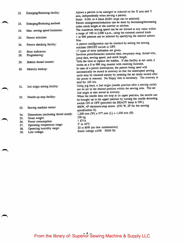
22. Enlarging/Reducing facility:
23. Enlarging/Reducing method:
24. Max. sewing speed limitation:
25. Pattern selection:
26. Pattern checking facility:
27. Error indication:
28. Programming:
29. Bobbin thread counter:
30. Memory backup:
31. 2nd origin setting facility:
32. Needle-upstop facility:
33. Sewing machine motor:
34. Dimensions (excluding thread stand):35. Gross weight:36. Power consumption:37. Operating temperature range:38. Operating humidity range:39. Line voltage:
Allows a pattern to be enlarged or reduced on the Xaxis and Yaxis, independently when sewing a pattern.Scale: 0.001 to 4 times (0.001 steps can be selected)Pattern enlargement/reduction can be done by increasing/decreasingeitherstitch length or the number or stitches.The maximum sewing speed can beset limited to any value withina range of180 to 2,000 s.p.m., using the external control knob.1 to 999 patterns can be selected by specifying the desired patternNos.
Apattern configuration can be checked by setting the sewingmachine ON/OFF switch to OFF.17types of error indication are given.Involves point/linear/arc numeral data, temporary stop, thread trim,jump data, sewing speed, and stitch length.TeUs the time to replace the bobbin. If this facility is not used, itworks as a 0 to 999 ring counter with resetting function.In case ofa power interruption, the pattern being used wiUautomatically be stored in memory so that the interrupted sewingcycle may be resumed simply by pressing the set ready switch afterthe jX)wer is restored. No floppy disk is necessary. The memory isheld for 100 hrs.
Using jog keys, a 2nd origin (needle position after a sewing cycle)can be set in the desired position within the sewing area. The set2nd origin is also stored in memory.When theneedle does not stop in its upper position, theneedle canbe brought up to the upper position by turning the needle threadingswitch ON or OFF (provided the READY lamp is ON.)400W, 4P electronic-stop motor (550 W, 2P for the sewingspecification G)1,200 mm (W) X977 mm (L) x 1,200 mm (H)250 kg1 KVA
5' to 40°C
20 to 80% (no dew condensation)Rated voltage ±10% 50/60Hz
- 4 -
From the library of: Superior Sewing Machine & Supply LLC
40. Air pressure used: 5 to 5.5 kgf/cm" (0.5 to 0.55 MPa)41. Air consumption: 1.8 N{/min.42. Input functions of the main unit: Zigzag sewing _|~ Spline
Offset sewing 1_ Curve, linear, pointDifferent types of sewing machine control (pattern erasing, threadtrimming, temporary stop, feeding frame up/down, speed changeetc.)Point adding, point moving, point erasing, inverting etc.
- 5 -From the library of: Superior Sewing Machine & Supply LLC
3. OPERATION
3-1. Names of the main components
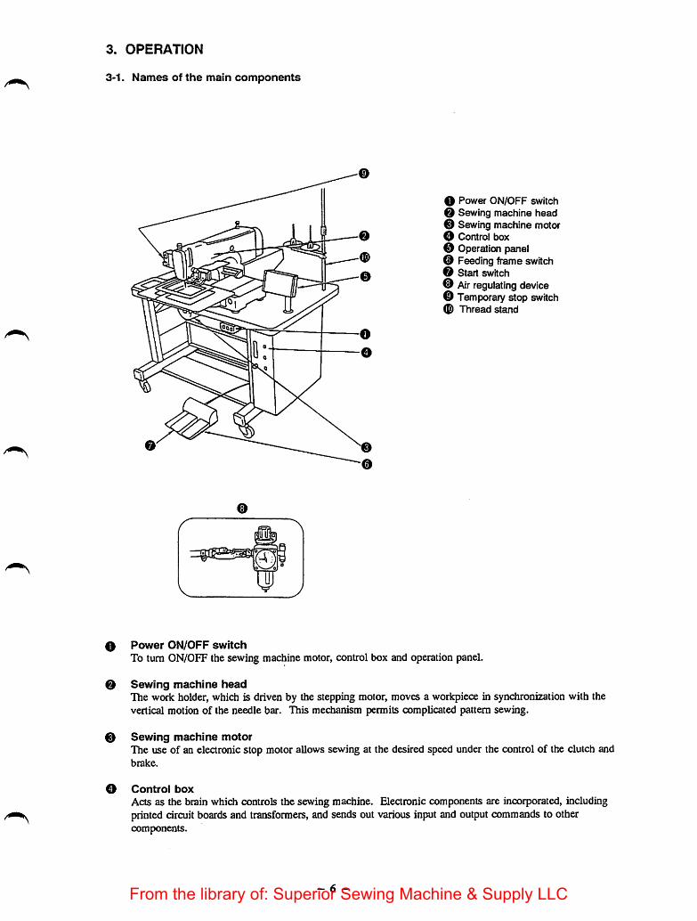
O Power ON/OFF switchO Sewing machine head0 SewingmachinemotorO Control box0 Operation panel© Feeding frameswitchO Start switch0 Air regulating device© Temporary stopswitch0 Thread stand
0 Power ON/OFF switchTo turn ON/OFF the sewing machine motor, control box and operation panel.
0 Sewing machine headThe work holder, which is driven by the stepping motor, moves a workpiece in synchronization with thevertical motion of the needle bar. This mechanism permits complicated pattern sewing.
0 Sewing machine motorThe use of an electronic stop motor allows sewing at the desired speed under the control of the clutch andbrake.
O Control boxActs as the brain which controls the sewing machine. Elearonic components are incorporated, includingprinted circuitboardsand transformers, and sends out various input and output commands to othercomponents.
- 6 -From the library of: Superior Sewing Machine & Supply LLC

0 Operation panelConsists mainly of switches, digital displays and a buzzer. It receives commands from the control box, andoutputs display data and switch information.The main unit input operation is performed whereby the pattern is input while moving the feed so as to adjustthe needle point.The memory switch is used for selecting operations and changingset values.
0 Feeding frame switchTurns ON/OFF the feeding frame solenoid at the time specified to lift or lower the feeding frame.
O start switchActs as the sewing command switch, andstarts sewing based on the data stored in the micro floppy disk.
0 Air regulating deviceConsists of the filter regulator, pressure gauge, air cock, pressure switch and other parts. It detects a drop inthe air source pressure, indicating it with an errorcode. The device is also used to adjust the operating airpressure during installation of the sewing machine.
0 Temporary stop switchPress this switch to stop the feed and sewing mechanism of the sewing machine during operation. When thisswitch is pressed during a stitching cycle, the machine stops without performing automatic thread trimming.At this state, the return to origin, forward and backward switches become valid after thread trimming hasbeen performed by raising or lowering the needle threadingswitch.
0 Thread stand
- 7 -From the library of: Superior Sewing Machine & Supply LLC
3-2. Control box panel
Roppy diskinsertion slot
Eject button
-m
Fig. 3-2
r
w
❖
E
Micro floppy disk
Shutter plate
Write protect tab
Write protect hole
Fig. 3-3
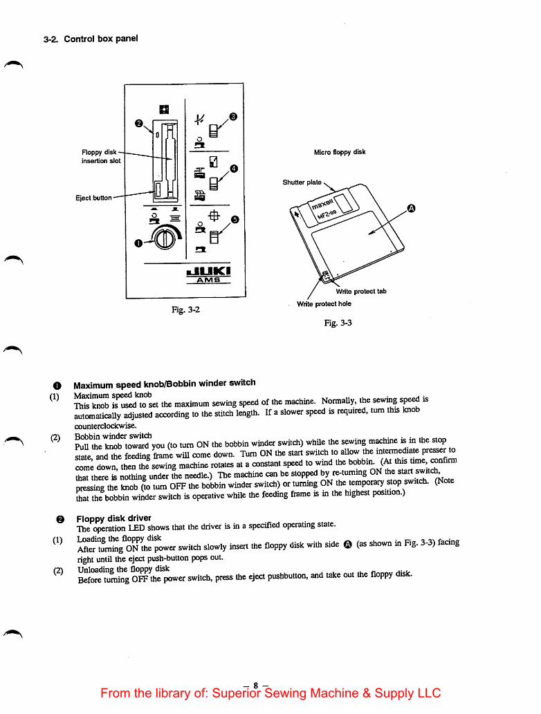
o Maximum speed knob/Bobbin winder switch
S^Tset the maximum sewing speed of the machine. NormaUy, the sewtag sj^ isautomaticaUy adjusted according to the stitch length. If aslower speed is required, rum this knobcounterclockwise.
m^Ae too? you (to turn ON the bobbin winder switch) while the sewing machine is in the «opstate and the feeding frame will come down. Turn ON the start switch to allow the intermediate presser tocome down, then the sewing machine rotates at a constant speed to wmd thethat there is nothing under the needle.) The machine can be stopped by re-tuming ON the start switc^pressing the knob (to turn OFF the bobbin winder switch) or turamg ON the temporary stop switch. (Nthat the bobbin winder switch is operative while the feeding frame is in the highest position.)
0 Floppy disk driverThe operation LED shows that the driver is in aspecified operating state.
^ter "ur^ng^ON the?^^ switch slowly insert the floppy disk with side ©(as shown in Fig. 3-3) faangright until theeject push-button pops out.
fiSore turning O^ toe power switch, press toe eject pushbutton, and take out toe floppy disk.
- 8 -From the library of: Superior Sewing Machine & Supply LLC

(3) Write-protect hole (Fig. 3-3)When the write-protect tab is moved so as to open the write-protect hole, it is no longer possible to writedata on to the disk. Do this to store programming data. For writing data on to the disk, move the write-protect tab until it is exposed.
[Caution]Never turn ON/OFF the power switch with the fioppy disk loaded.
(4) Micro floppy disk (Fig. 3-3)Precautions when handling and storing the floppy disk1) Do not open the shutter and touch the magnetic surface.2) Do not apply pressure on the shutter plate or the opening/closing spring (slider), or else the disk may
become damaged.3) Do not allow the hub to become damaged and do not use the disk with dust on the hub, or else errors
may occur. Always keep the hub clean.4) Do not use thinner, alcohol or Freon gas on the disk.5) Do not use erasers on the disk.6) Do not eat or drink near the disk.7) Do not store the disk in a place where there is a magnetic field.8) Do not store the disk in a dusty place.
e Needle threading switch(1) When the needle threading switch is pressed side while the sewing machine is stopped, the intermediate
presser and the feeding frame will come down to allow the needle to be threaded. If the start switch ispressed during needle threading, the sewing machine will not run.
(2) When the temporary stopswitch is pressed ON and thesewing machine is stopped, the return to origin,forward and backward switches become valid after thread trimming has been performed, by raising orlowering the needle threading switch.If theneedle is notat its highest resting position (error [3]), the madiine will be automatically driven andthen stopped with the needle up, by raising/lowering the needle threadingswitch. Prior to the aboveoperation, be sure that there is nothing under the needle. (The needle threading switch is valid while thesewing LED is lit up.)
O Scale switch (INC/DEC of Number of stitches)Taking a pattern written on the floppy disk as 100%, the original pattern can be enlarged or reduced in theX-axis and/or Y-axis independently within a range of 0.1% to 400%. The enlargement or reduction of apatternis set either by increasing or decreasing the stitch length or the numberof stitches. Patternenlargement or reduction data is read for computation while the Set Ready indicator lamp is ON. Forpointinput, the enlargement or reduction of a pattern is always done by increasing or decreasing the stitch length.
0 Sewing machine ON/OFF switchWhen the program to operate the sewing machine is stored in the floppy disk, the machine will performnormal sewing operation according to the program by setting the sewing machine switch to the ^ position.When this switch is set to the position, only the feed mechanism will work.Whenever enlarging/reducing a pattern or sewing a newly programmed pattern, set this switch to the 131position to check the shapeof the pattern in the program. After completing the check, set the switch to the
position to start sewing.
- 9 -From the library of: Superior Sewing Machine & Supply LLC
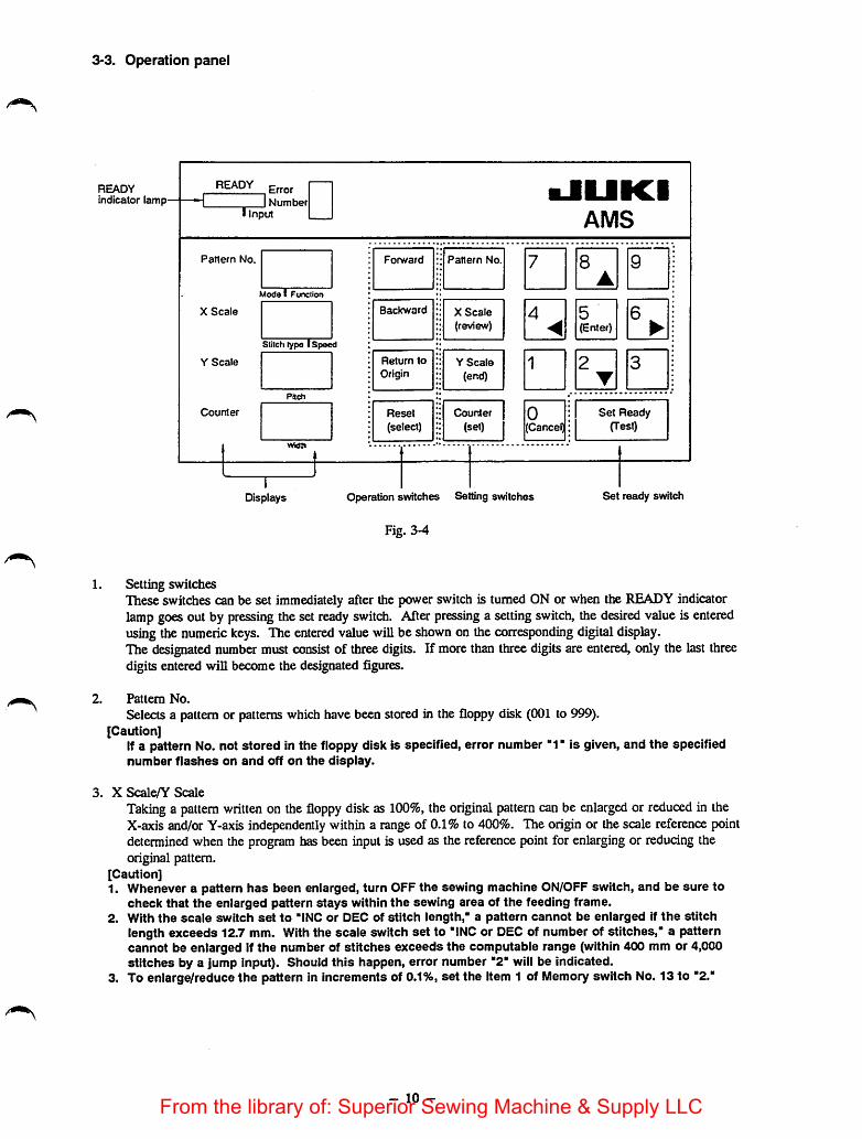
3-3. Operation panel
READYindicator lamp-
RE^ ErrorINumber
I Input
•JUICIAMS
Pattern No.
X Scale
Y Scale
Counter
Forward Pattern No. 7 8•
9
Model Funclion
Backward X Scale
(review)4
<5(Enter)
6•
Stitclitype i Speed
Return to
OriginY Scale
(end)1 2
T3
Pijch
Reset
(select)Counter |
(set) 10(Cancel)
:1 Set Ready:| (Test)
Misn
Displays Operation swKches Setting switches
Fig. 3-4
Set ready switch
Setting switchesThese switches can be set immediately after the power switch is turned ON or when the READY indicatorlampgoes out by pressing the set ready switch. Afterpressing a setting switch, the desired value is enteredusing the numeric keys. The entered value will be shownon the corresponding digitaldisplay.The designated number mustconsist of three digits. If more than threedigitsare entered, only the last threedigits entered will become the designated figures.
Pattern No.
Selects a pattern or patterns which have been stored in the floppy disk (001 to 999).[Caution]
If a pattern No. not stored in the floppy disk is specified, error number "1" is given, and the specifiednumber flashes on and off on the display.
X Scale/Y Scale
Taking a pattern written on the floppy disk as 100%, the original pattern can be enlarged or reduced in theX-axis and/or Y-axis independently within a range of 0.1% to 400%. The origin or the scale reference pointdetermined when the program has been input is used as the reference point for enlargingor reducing theoriginal pattern.
[Caution]1. Whenever a pattern has been enlarged, turn OFF the sewing machine ON/OFF switch, and be sure to
check that the enlarged pattern stays within the sewing area of the feeding frame.2. With the scale switch set to "INC or DEC of stitch length," a pattern cannot be enlarged if the stitch
length exceeds 12.7 mm. With the scale switch set to "INC or DEC of number of stitches," a patterncannot be enlarged if the number of stitches exceeds the computable range (within 400 mm or 4,000stitches by a jump input). Should this happen, error number "2" will be indicated.
3. To enlarge/reduce the pattern in increments of 0.1%, set the Item 1 of Memory switch No. 13 to "2."
- 10 -From the library of: Superior Sewing Machine & Supply LLC
4. Counter
Counts the number of garments sewn, and indicates when to replace the bobbin by means of an alarm. Whenthe quantity of the bobbin thread has been reduced to the preset level, the counter flashes on and off urgingyou to replace the bobbin. Sewing is not possible while the counter is flashing on and off. Press the resetswitch after replacing the bobbin, and the counter will be reset to "000", allowing the machine to be restarted.(The counter switch is turned OFF at the time of delivery.)
5. Set ready switch/READY (Sewing LED)Sets off the following series of operation when pressed after setting the pattern No., X/Y scale, counter andscale switch (INC/DEC of stitch length or INC/DEC of number of stitches):1) The specified pattern or patterns are read from the floppy disk.2) Operation is performed based on the entered scale data. While the compulation is being executed, the
sewing LED (READY) flashes on and off.3) Upon completion of the computation, the feeding frame comes down, automatically moves via the origin
to the sewingstart point (the 2nd origin if the 2nd origin has beenset), and then goes up.
[Caution]Remember that the above-mentioned series of operation to set the machine ready for sewing isperformed only when the power switch is turned ON.
4) The READY lamp is continually lit instead of flashing on and off, showing that the machine is ready tostart sewing. Note that you are not allowed to make any setting changes while the READY lamp is ON.To make a setting change in this case, press the set ready switch. This will cause the READY lamp to goout, thus permitting a setting change.
[Caution]Do not put your fingers under the feeding frame since the feeding frame automaticaiiy comes downon completion of computation, if the pattern No. or X/Y scale is not changed, the pattern which hasbeen used until the power is turned OFF can be sewn by simply turning ON the set ready switch. Atthis time, the floppy disk is not required.
6. Forward/Backward
When the forward switch is pressed with the feeding frame down, the material is fed forward by one stitch.When the backward switch is pressed with the feeding frame down, the material is fed backward by onestitch. If these switches are kept pressed, the material is fed slowly for the first stitch, after which it isautomatically fed quickly.
7. Return to originWhen this switch is pressed during a temporary stop, the feeding frame will automatically move to thesewing start point or the 2nd origin, and the feeding frame will go up and stop.
8. Jog keys (Numeric key 2, 4, 6, 8: A mark)These keys function as numeric keys while the READY lamp is OFF, and work as jog keys while theREADY lamp is ON. If any of these keys is pressed with the feeding frame down at the sewing start, theneedle will move in the direction shown by the arrow on the pressed key. At this time, the movement of theneedle is automatically stored in memory. Set the 2nd origin at the desired position within the materialfeeding range.
9. Reset
Resets the counter value when pressed after a temporary stop following a press of the set ready switch orcompletionof pattern sewing. If the reset switch is pressed while the counter is flashing on and off, the totalvalue indicated on the counter will be reset.
- 11 -From the library of: Superior Sewing Machine & Supply LLC
10. Error No. displayifVny of the foliowing errors occurs, i. will be indicrrted by an "Error Number," and no furrher operarion wiU
Error code Description
1 Pattern No. error and read error.
2 Enlargemoit error
3 Needle up error
4 Sewing area error
5 Temporary stop fedication
6 Memory capacity indication
7 Machine lock or needle position error
8 Solenoid connector error
9 Thread breakage indication
0 Micro floppy disk format error
A Air pressure drop (less than 4kgf/cm^ errorE Sewing machine reverse rotation error
11, Electronic bu22erThe electronic buzzer beeps each time a switch is pressed.
3-4. Other switches
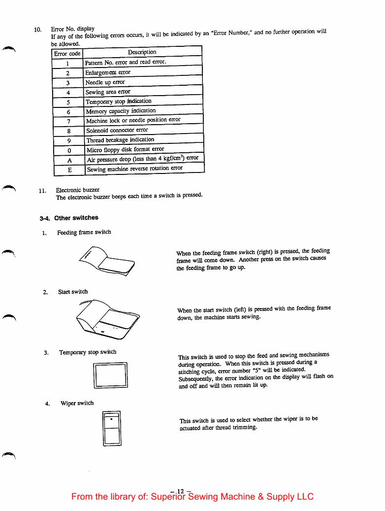
1, Feeding frame switch
2. Start switdi
3. Temporary stop switch
Wiper switch
When the feeding frame switch (right) is pressed, the feedingframe will come down. Another press on the switch causesthe feeding frame to go up.
When the start switch (left) is pressed with the feeding framedown, the machine startssewing.
This switch is used to stop the feed and sewing mechanismsduring operation. When this switch is pressed during astitching cycle, error number "5" will be indicated.Subsequently, the error indication on the display will flash onand off and will then remain lit up.
This switch is used to select whether the wiper is tobeactuated after thread trimming.
- 12 -From the library of: Superior Sewing Machine & Supply LLC

3-5. Checking before operation
1. Be sure that the line voltage is suitable for the machine table.
2. Be sure that the needle stays within the feeding frame.
3. Be sure that the needle entry point is set at the center of the intermediate presser.
4. Be sure that no micro floppy is in the disk driver.[Caution]
If the power switch is turned ON/OFF with a micro floppy disk loaded, the data stored in the disk maybe erased. So be sure to load or unload the disk while the power is ON. Also, be sure to write-protectthe disk except when writing data on the disk.
5. Check the direction of rotation of the sewing machine as follows:When the bobbin winder switch is turned "ON" upon completion of sewing preparation, the feeding framewill come down. The sewing machine will then run when the start switch is pressed. At this time, checkthat the pulley turns counterclockwise as observed from the pulley side. If the pulley turns in the oppositedirection, correa it by reversing the motorpowerplug connection, i.e., turn the plug 180 degrees beforereconnecting it.
[Caution]Be sure to turn OFF the power switch before connecting or disconnecting the motor power plug. Also,be sure to securely connect the plug.
6. Check the oil level
Lubricate the machine (there are two lubrication holes) until the oil level readies the red mark on the oilgauge. Before starting the sewing machine which has just been installed or which has not been used for along period of time, apply a few drops of lubricating oil to the crank assembly through the crank lubricatinghole, and one drop to the shuttle race surface.
7. Remove the bed fixing bolt beforestartingoperation. Install the bed jBxing bolt at the time of transportation.
8. When the polyethylene oiler is completely filled with oil, remove the oiler so that it can drain.
9. Compatibility of floppy disksFor the AMS-A type floppy disk (ID) and AMS-B typefloppy disk (2DD), data can only be read fromthem.
The floppy disk (2DD) for the AMS-215C cannot be used with the AMS-A type, AMS-B type, AMS-210C,-212C and -22QC models of sewing machines.
- 13 -From the library of: Superior Sewing Machine & Supply LLC

3-6. Operation procedure
Follow the operation procedureflow chart given below:
3
Preparationfor sewing
YES
c Start
Set the s
on the cc
witches
ntrol box
turn uN the
power switch
Set the switchesthe panel?
YES
Pattern No
X-scale
Y-scale
Counter
Load the disk
Press the set
readv switch
Data back-up?
N 0
Reads the dataComputes the Xand Y-scales
YES
Turn OFF the power switchThe feeding framecomes down
Troubleshooting
Immediately after^the power switchis turned ON?--*^
TvesFeeds along the travellimits of the X/Y axis.
N 0
- 14 -
Sewing machine ON/OFF switch — OFFINC/DEC of the stitch length or the number ofstitches -• select either of them.Bobbin winder switch -• OFFNeedle threading switch -• OFF
Sewing machine motor starts to run.Operation petnel indicator lamps light up.
READY lamp flashes on and offduring thecomputation.
Error indication *A' {air pressure drop error)Error indication No. "3* (needle up error)(See P. 165 for the error indication)
Performed once after the power switch is turned ON
From the library of: Superior Sewing Machine & Supply LLC
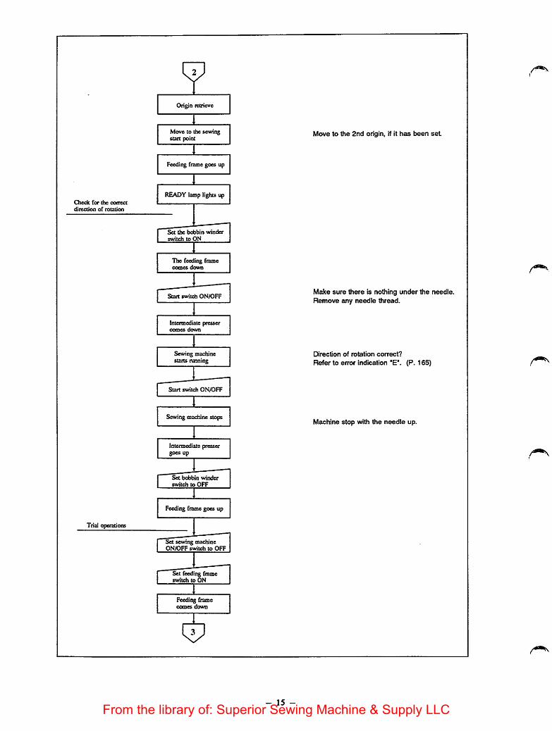
Check for the correct
direction of rotation
Trial operations
Origin retrieve
Move to the sewingstart point
IFeeding frame goes up
1READYlamp lights up
I Srttte bo1 switch to
bbin winderDN
The feeding fiamecomes down
Start switch ON/OFF
Intermediate pressercomes down
Sewing machinestarts running
Start switch ONADFF
Sewing machinestop
Intermediatepressergoes up
Set bobbin winderswitch to OFF
Feedingframegoes up
&t sewing machineON/OFF switch to OFF
Set feeding frameswitch to ON
Feeding framecomes down
- 15 -
Move to the 2nd origin, if it has been set
Make sure there is nothing under the needle.Remove any needle thread.
Direction of rotation correct?
Refer to error indication "E". (P. 165)
Machine stop with the needle up.
From the library of: Superior Sewing Machine & Supply LLC
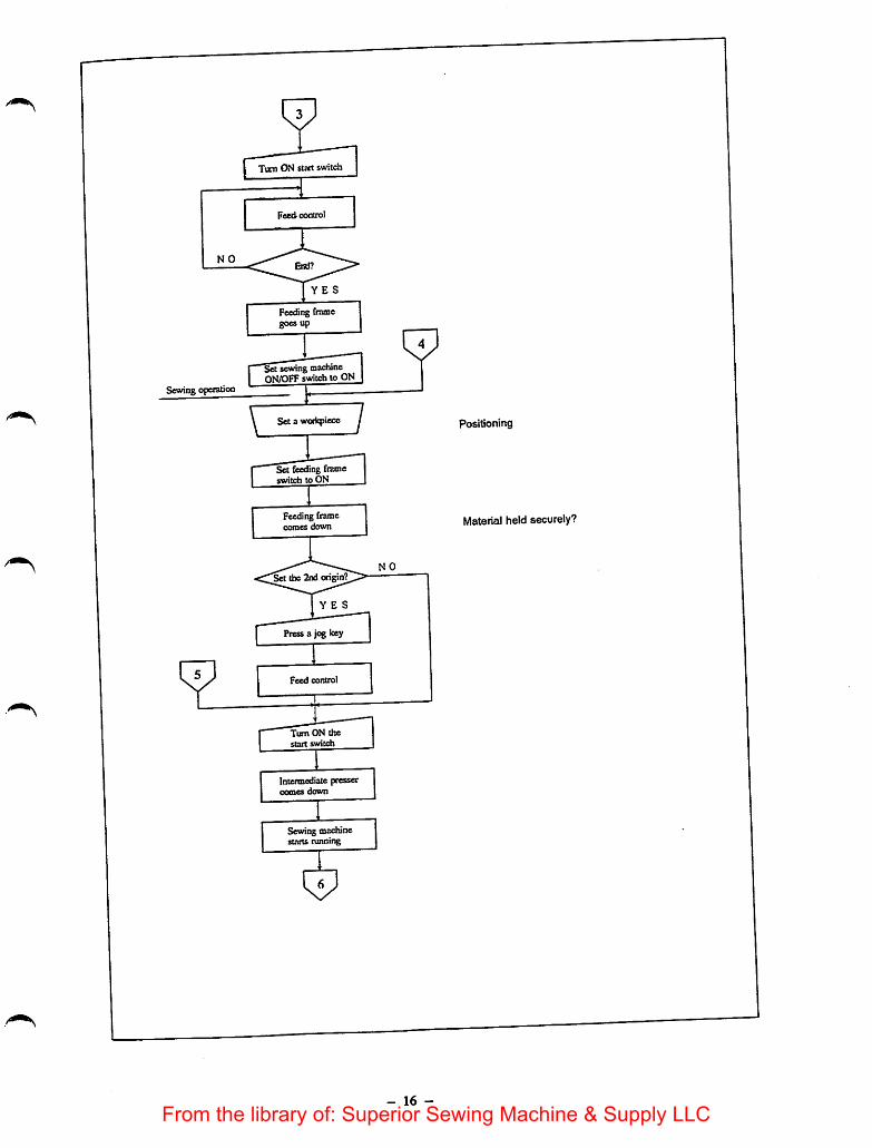
Sewing operation
Turn ON start switch
Fceti control
YES
Feedingframegoes up
Set sewing machineON/OFFswitchto ON
Sec a woriqiiece
Set feeding frameswitch to ON
Feeding framecomes down
ongin
YES
Feed control
Turn ON thestart switch
Intermediate pcessercomes down
Sewing machinestarts running
Positioning
Material held securely?
- 16 -
From the library of: Superior Sewing Machine & Supply LLC

NO
Sewing
.Needle thread broken?'
NO
Temporary stop?
NO
End?
YES
Thread trimmer isactuated
Sewingmachine stops
Wper is actuated
Returns to thesewing start point
Feeding frame goesup
One cyclecompleted
' Display setting-
YES
Set the set readyswitch to ON
YES
NO
Turn ON the temporarystopswitch
<3^
- 17 -
Thread tension balanced?
Returns to the 2nd origin, if it hasbeen set.
Reset the Counter.
From the library of: Superior Sewing Machine & Supply LLC

Operation stopped due to L ^n^le thread breakage.
NO
Feed contro] stop
Thread trimmer
is actuated
Sewing machinestops
Wiper is actuated.
Intermediate pressergoes up
Return to ongin
YES
YES
YES
Feed control
lum UN the returnto origin switch
Move to the
sewing stait pdnt
Feedii^ framegoes up
- 18 -
Threading ttie machine
Move to the 2nd origin, if it hasbeen set
From the library of: Superior Sewing Machine & Supply LLC

Teoipotaiy stop opeiation
N O
Stop feed control
During sewing?
YES
Sewing machinesstops
Intermediate prcsscrgoes up
Re-start?
Thread trimming?
YES
"Turn ON the needlethreading switch
Intermediate pressercomes down
I 'tTurn OFF the needlethreading switch
Sewing machine runs.
The thread trimmeris actuated
Sewing machinestops
tViper is actuated
Intermediate pressergoes up
NO
i:?
YES Eliminate the cause of the temporary stop.
- 19 -From the library of: Superior Sewing Machine & Supply LLC

3-7.
. 1.
Precautions during operation^ tt<>m be sure to carry out trial sewing to check th
Before sewing anew pattern or anewly enlarged pattern, be sureflae with respect to .be feeding ffante.
sewing speed according to the typ sewina speed (s.p.m.)
When an error indication is given, be sure toidentify the cause and take corrective action.
prevent dust from getting into the control^ (^\fexv weCiC*
riTTc Ks.fnrp ooenins the control box cover.5. Be sure to turn the power OFF before openmg pe applied to sen.iconduc.or, • -.rv hv 1tester or else the tester voltage may be applir^nt^:Srr;ri,bedan,ag«.. ^ .,0nbobbin.
1 the needle before depressing the start swiiui
completion of the computanon. „ Xor Yneedle entry
9. Avoid pulling the workpiece f the corr^t sewing start point,point should be dislocated, press the Set Reaay
- 20 -
From the library of: Superior Sewing Machine & Supply LLC
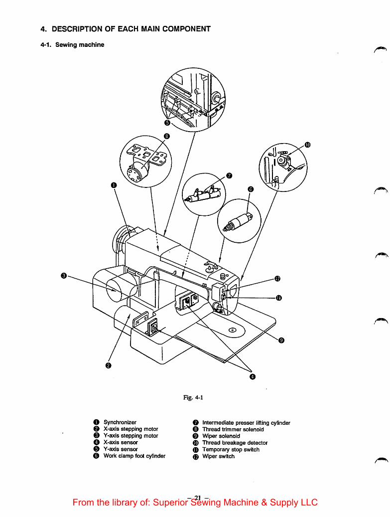
4. DESCRIPTION OF EACH MAIN COMPONENT
4-1. Sewing machine
Fig. 4-1
O Synchronizer OX-axis stepping motor OY-axis stepping motor 0
O X-axis sensor0 Y-axis sensor 00 Work damp foot cylinder 0
Intermediate presser lifting cylinderThread trimmer solenoid
Wiper solenoidThread breakage detectorTemporary stop switchWiper switch
- 21 -From the library of: Superior Sewing Machine & Supply LLC

O SynchronizerMainly consists of a generator stator and position detecting solenoid incorporated into the sewing machinepulley. It detects whether the needle is in its upper or lower position, and also detects the sewing speed, afterwhich it sends input signals to the control box based on the detection results.
X-axis stepping motorFeeds material in the direction of the X-axis according to the pattern data given by the control box.
O Y-axis stepping motorFeeds material in the direction of the Y-axis according to the pattern data given by the control box.
O X-axis sensorMainly consists of an X-axis slit disk, an X-axis originsensorand an X-axis travel limit sensor. It detectsthe origin in the X-axis within the sewing areaand the boundary of the limited sewing area. It sends theinput signals to the control box based on the detection results.
0 Y-axis sensorMainly consists of a Y-axis slit disk, a Y-axis origin sensorand a Y-axis travel limitsensor. It detects theorigin in the Y-axis within thesewing area and theboundary of the limited sewing area. It sends the inputsignals to the controlbox based on the detection results.
0 Work clamp foot cylinderBy turning ON/OFF the feeding frame switch, the feeding frame activated by the air cylinder goes up andcomes down to securely hold the material.
O Intermediate presser lifting cylinderDuring sewing, theair cylinder controls the vertical stroke path of the intermediate presser, and actuates theintermediate presser causing it to go up and come down.
0 Thread trimmer solenoidActuates the clutch mechanism for the thread trimmer according to the command from the synchronizer. Itthenactuates causing the thread trimmer cam and thread trimmer mechanism to join together.
0 Wiper solenoidActuates the wiper after the thread has been trimmed.
<0 Thread breakage detectorDetects the connection between the thread take-up spring and the thread breakage detector disk each time astitch is formed, and sends the result in terms of an input signal to the control box. If needle thread breakageis detected, the sewing machine will slow down, trim the thread, and stop.
0 Temporary stop switchThisswitch is used to stop the feed and operation of the sewing machine during sewing. If this switch isturned ON, the machine will stop without performing thread trimming.
0 Wiper switchUsed to specifywhether the wiper is to be actuated after thread trimming.
- 22 -From the library of: Superior Sewing Machine & Supply LLC

4-2. Control box
O CPU circuit boardl/F circuit board
O PMDC circuit boardo Power circuit boardO Switching regulator
"\
Fig. 4-2
0 TransformerO Fuse boxO Cooling fan0 Floppy disk driver
- 23 -
From the library of: Superior Sewing Machine & Supply LLC
receiving the reset signal from the I/F circuit.. T^cincluding ICs.• Floppy disk drive conirol arcuit• Microprocessor control circuit• Input circuits for the switches. Switch signal output circuit
I/F circuit board lender solenoid valve after board.U the sewing machine or operation panel
The following circuits are mounted.• Magnet actuating circuit. Display actuating circuit. Solenoid valve actuating arcuit. Sewing machine actuating arcuit
) PMDC circuit board receiving the control signal from the CPU circuit board throughActivates the stepping motor after receivmgcircuit board. It includes;
^ • Current limiter circuit. Stepping motor driving circuit
the outputs received from the secondary transformer to provide the power supply, and
: C^4v'S^^"circuit for the PMDC circuit board. +5V, +12V, -12V wiring circuits
® »"ut from the secondary transformer and outputs .5V. .12V and -HV.0 Transformer 50V AC for the stepping motor actuator, lOOV AC for the coo g
lag fuse to protea the solenoids, alOA fuse to protect the stepping motor and switching^Str-daTlitle'toprotLtthetmoUngfan.
0
o
Cooling fan „ ^ j ^ron, outside the machine.Used to cool the elements, taking mfresh air
the CPU drcuitboard
- 24 -
From the library of: Superior Sewing Machine & Supply LLC

4-3. Operation panel
Fig. 4-3
O Operation circuit boardO Operation panel relay cable
O Operation circuit boardOn this circuitboard are mounted display parts which receive commands from the control box and switchparts which send switch data to the control box.
0 Operation panel relay cableThis isa 50-core cable which .connects the operation circuit board with the control box for transfer ofsignals.
- 25 -From the library of: Superior Sewing Machine & Supply LLC
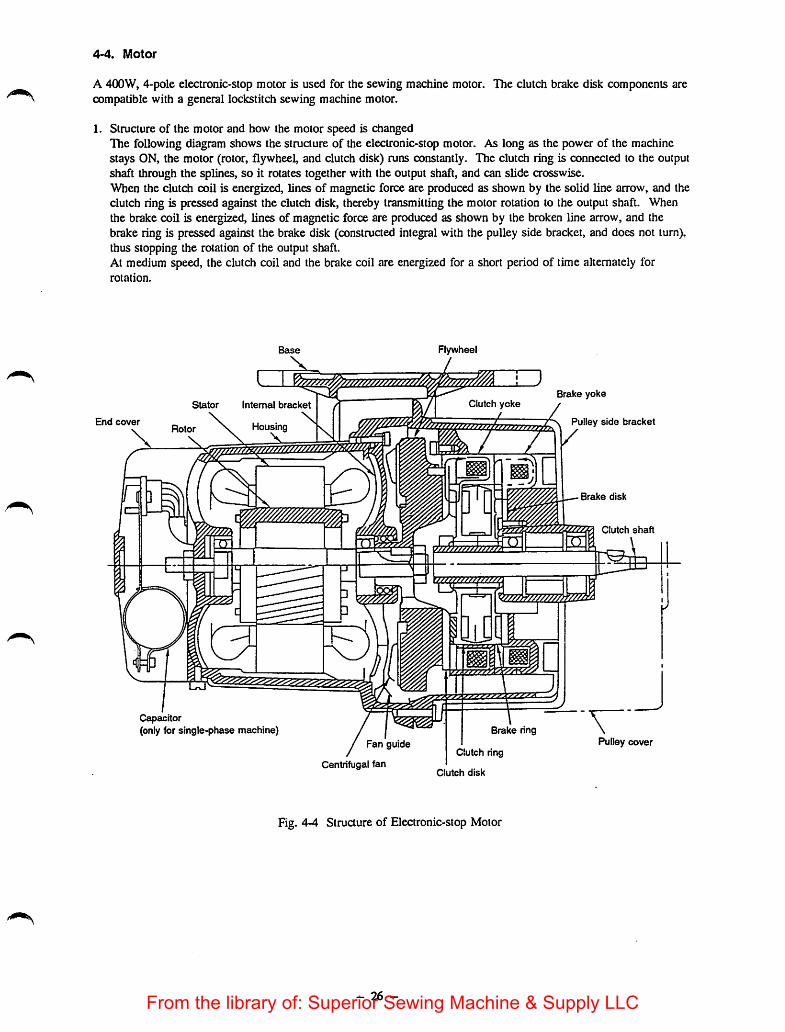
4-4. Motor
A 400W, 4-pole electronic-slop motor is used for the sewing machine motor. The clutch brake disk components arecompatible with a general lockstitch sewing machine motor.
1. Structure of the motor and how the motor speed is changedThe following diagram shows the structure of the electronic-stop motor. As long as the power of the machinestays ON, the motor (rotor, flywheel, and clutch disk) runs constantly. The clutch ring is connected to the outputshaft through the splines, so it rotates together with the output shaft, and can slide crosswise.When the clutch coil is energized, lines of magnetic force are produced as shown by the solid line arrow, and theclutch ring is pressed against the clutch disk, thereby transmitting the motor rotation to the output shaft. Whenthe brake coil is energized, lines of magnetic force are produced as shown by the broken line arrow, and thebrake ring is pressed against the brake disk (constructed integral with the pulley side bracket, and does not turn),thus stopping the rotation of the output shaft.At medium speed, the clutch coil and the brake coil are energized for a short period of time alternately forrotation.
Stator Intemal bracket
End cover „\ RotorX ^
,— ^ ^
Clutch yoke
Capacitor
Housing
machine)
Centrifugal fan
/WWW/,
Clutch
Clutch disk
Fig. 4-4 Structure of Electronic-stop Motor
- 26 -
Brake yoke
Pulley side bracket
Brake disk
Clutch shaft
Pulley cover
From the library of: Superior Sewing Machine & Supply LLC

5. ADJUSTMENTS
5-1. Mechanical parts
STANDARD ADJUSTMENTS
(1) Checking the direction of rotation of the handwheelAfter confirming that the READY indicatorlamp has lit up, set the bobbin winder switch to"ON", and press the start switch. At this time,the handwheel should turn counterclockwise (inthe direction of the arrow) as observed from thepulley side. If the handwheel turns in thereverse direction, error will be indicated,and the madiine wiU stop.
[Caution]Be sure to check the direction of rotation of
the handwheel after the machine has been
installed or the powers supply wiring of themachine has been completed.Do not start sewing unless the direction ofrotation of the handwheel has been
confirmed as correct.
ft&ADY
1 iNumberj 1lln^ 1
PdRernNa
XScato
SMo»tm*iseM0
YScato
Coiirter
Fig. 5-1-1
(2) Height of the needle barBring the needle bar to the lowest dead point in its stroke. Adjust so that the bottom end of the needlebar lower bushing is aligned with the upper marker line (for a DPx5 or DPxl7 needle).
D
Fig. 5-2-1
Marker lines for
the DPx5 needle-
Marker lines for
the DPx17 needle
Needle bar
lower bushing
Upper marker line
V Marker lines forthe DPx17 needle(with needle count
^of#22 or higher)
Fig. 5-2-2
[Caution]The marker lines for DPx17 (#22 or higher count) are only engraved on the needle bar of the sewingmachine of which specification code G.
- 27 -
From the library of: Superior Sewing Machine & Supply LLC
now TO ADJUST
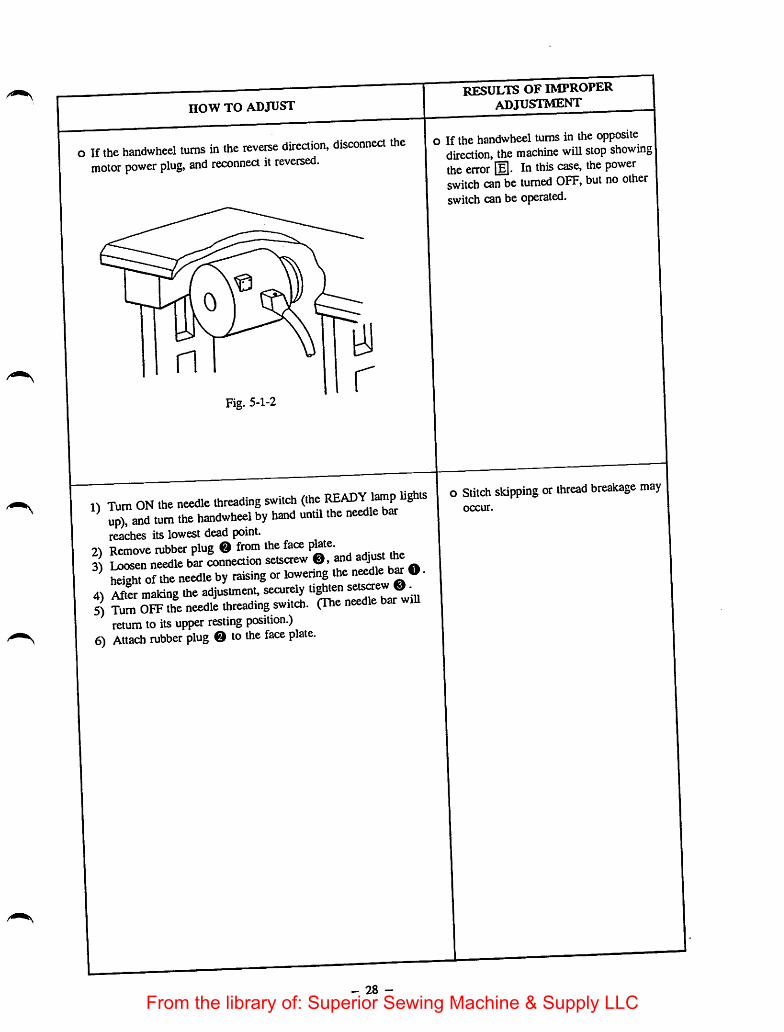
o If the handwheel turns in the reverse direction, disconnect themotor power plug, and reconnect it reversed.
0
n
Fig. 5-1-2
1) Turn ON the needle threading switch (theup), and turn the handwheel by hand until the needle barreaches its lowest dead point.
2^ Remove rubber plug 0 from the face p^te.3^ Loosen needle bar connection setscrew 0, and adjust me^S o? the needle by raising or lowering the needle O•
4) After making the adjustment, securely bar will5) Turn OFF the needle threading switch. (The needle bar illreturn to its upper resting position.)
6) Attach rubber plug 0 to the face plate.
- 28 -
RESULTS OF IMPROPERadjustment
o If the handwheel turns in the oppositedirection, the machine will stop showingthe error E. In this case, the powerswitch can be turned OFF, but no otherswitch can be operated.
o Stitch skipping or thread breakage mayoccur.
From the library of: Superior Sewing Machine & Supply LLC

STANDARD ADJUSTMENTS
(3) Stop position of the main shaftWhen the main shaft stops, marker dot O on themachine arm should be midway between marker dotNo. 1 O and marker dot No. 2 on the handwheel.For the sewing machine of which specification code isG, adjust so that marker dot O engraved on themachine arm rests between upper blue marker dot 0and lower marker dot 0 engraved on the handwheelwhen the sewing machine stops.
[Caution]1. Be sure to do this adjustment while the machine is
ready to start sewing.2. This adjustment is unnecessary for normal
operation. If the stop position of the main shaft hasbeen adjusted, be sure to check the newly adjustedstop position of the main shaft with the workpieceset on the machine.
(4) Height of the Intermediate presser1) Make sure that thesewing pattern data has been read
and thesewing indication LED (READY lamp) has litup before setting the workpiece on the machine.
2) Makesure that the needleentry point is in the centerof intermediate presser O-
3) Set Needle threading switch 0 in the control box tothe 4^ side. The feeding frame and intermediatepresser will then come down.
4) Turn the handwheel by hand until the needle barreaches the lowest dead point of its stroke. Adjust sothat a 0.5 mm (standard adjustment value) clearance isobtained between the top end of the intermediatepresser and the workpiece.
5) After making the adjustment, setNeedle threadingswitch 0 to the side. The machinewill thenrun until it reaches the needle-up stop position. (Themaximum thickness of the material to be sewn usingthe intermediate presser is 5 mm.)
- 29 -
Workpiece
Direction
of rotation O
Fig. 5-3-1
Throat plate
Fig. 5-4-1
From the library of: Superior Sewing Machine & Supply LLC

3)
4)
HOW TO ADJUST
Loosen solenoid mounting basesetscrew O.If the main shaft stops prematurely before marker dot No.l Oor 0 on the handwheel reaches marker dot O on the machinearm, move setscrew O in the direction of arrow (D and thentighten the setscrew in that position. On the other hand, if themain shaft stops after marker dot No. 2 0 or 0 passes beyondmarker dot O, move setscrew O in the direction of arrow 0,and then tighten the setscrew in that position.Repeat step 1), 2) until marker dot O on the machine arm islocated between marker dot No. 1 0 or 0 and marker dot No.20 or 0 on the handwheel when the main shaft stops.Securely tighten solenoid mounting base setsaew O.
Direction of rotation
The msu'ker dot O on themachine arm stops at themetrker dot No. 1 side on
the handwheel.
Direction of rotation
The markerdot O on themachine arm stops at themarker dot No. 2 side on
the hcuidwheel.
o Loosen intermediate presser setscrew 0, and adjust the heightof the intermediate presser following the procedurestated on theleft. Upon completion of the adjustment, tighten the setsaew.
Be sure to adjust the height of the intermediate presseraccording to the thickness of the material or the typeof thread to be used so that the material does not flapduring sewing. When sewing floppy material, adjustso that there is no clearance (0 mm),
o After adjusting the height of the intermediate presser, be sure tocheck the position of the wiper(Refer to "STANDARDADJUSTMENTS (9).")
- 30 -
RESULTS OF IMPROPER
ADJUSTMENT
If the main shaft stops before marker dotO reaches marker dot No. 1 0 or 0on the handwheel:
Thread trimming operation cannot becompleted (the main shaft stops beforethe moving knife meets the counterknife), leading to thread trimmingfailure.
If the main shaft stops after marker dotNo. 2 0 or 0 passes beyond markerdot O on the machine arm:A clearance of 1 mm or greater shownin the figure cannot be obtained, and thewiper and intermediate presser will comein contact with the needle, which maycause the needle to bend or break.
1 mm or more
i
1mm or more
o If the clearance is too great:Stitch skipping may occur,
o If the clearance is too small:
Loose stitches may result.
From the library of: Superior Sewing Machine & Supply LLC

STANDARD ADJUSTMENTS
(5) Feed bracketAdjust the clearance between the feeding frame and thesurface of the throat plate when the feeding frameis in its upper resting position. (Maximum clearance30 mm.)
0
Fig. 5-5-1
(6) Shuttle race springAdjust the lateral position of theshuttle race springso that the center of the needle is aligned with thecenter of groove width @.Adjust the longitudinal position of theshuttle race spring so that the rear end of the needle is alignedwith comer point © ,
[Caution]If section © is damaged, thread breakage or thread splitting might occur, or the thread mightbecome dirty. Be sure to buff both faces of section ©. Be sure to buff the back side of the springwith care.
Fig. 5-6-1
- 31 -From the library of: Superior Sewing Machine & Supply LLC
now TO ADJUST
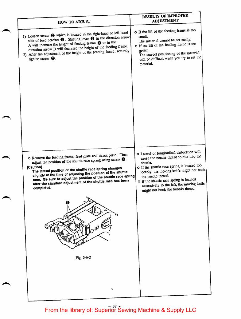
n Loosen sctcw 0 which is located in the right-hand or left-hand^ b®kct o. Shifting lever ®in the dir^.on am>w|Awill increase the height of feeding frame O .din arrow Bwill decrease .he heigh, of .he ^
2) After the adjustment of the height of the feeding frame, securelytighten saew 0.
o Remove ttie feeding frame, feed pla.e andadjus. .he posWon of ttie shuffte race spring usmg screw U•
position of the shuttle race ^'"9 f
Ster" the standard adjustment of the shuttle race has beencompleted.
0
Fig. 5-6-2
- 32 -
results of improperadjustment
o If the lift of the feeding frame is toosmall;
The material cannot beset easily,o If the lift of the feeding firame is too
great:The correct positioning of the matenaiwill be difficult when you try to set the|material.
o Lateral or longitudinal dislocation willcause the needle thread tobite into theshuttle.
o If the shuttle race spring is located toodeeply, the moving knife might not hookjthe needle thread,
o If the shuttle race spring is locatedexcessively to the left, the moving knifemight not hook the bobbin thread.
From the library of: Superior Sewing Machine & Supply LLC
STANDARD ADJUSTMENTS
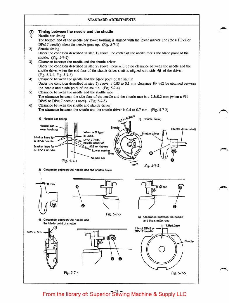
(7) Timing between the needle and the shuttle1) Needle bar timing
The bottom end of the needle bar lower bushing is aligned with the lower marker line (for a DPx5 orDPxl7 needle) when the needle goes up. (Fig. 5-7-1)
2) Shuttle timingUnder the condition described in step 1) above, the center of the needle meets the blade point of theshuttle. (Fig. 5-7-2)
3) Clearance between the needle and the shuttle driverUnder the condition described in step 2) above, there will be no clearance between the needle and theshuttle driver when the end face of the shuttle driver shaft is aligned with side © of the driver.(Fig. 5-7-2, Fig. 5-7-3)
4) Clearance between the needle and the blade point of the shuttleUnder the condition described in step 2) above, a 0.05 to 0.1 mm cle<irance © will be obtained betweenthe needle and blade point of the shuttle. (Fig. 5-7-4)
5) Clearance between the needle and the shuttle raceThe clearance between the side face of the needle and the shuttle race is a 7.5±0.2 mm (when a #14DPx5 or DPxl7 needle is used). (Fig. 5-7-5)
6) Clearance between the shuttle and shuttle driverThe clearance between the shuttle and the shuttle driver is 0.5 to 0.7 mm. (Fig. 5-7-2)
1) Needle bar timing
Needle bar
lower bushing
Marker lines for
a DPxS needle
Marker lines for
a DPx17 needle
When a G typeis used.
DPx17 (withneedle count of
if22 or higher)Lower marker
lines
Needle bar
Fig. 5-7-1
3) Clearance between the needle and the shuttle driver
0 mm
\
Shuttle
d
Fig. 5-7-3
4) Clearance between the needle andthe blade point of shuttle
JL/®0.05 to 0.1 mm-«
S
Fig. 5-7-4
O 0
- 33 -
2) Shuttle timing
Shuttle driver shaft
Shutt e dnver
Fig. 5-7-2
5) Clearance between the needleand the shuttle race
#14 of DPxS or —»DPx17 needle
7.5st0.2mm
Shuttle
Fig. 5-7-5
From the library of: Superior Sewing Machine & Supply LLC

now TO ADJUST
1) Refer to "STANDARD ADJUSTMENTS (7)-!)," and adjust sothat the lower marker line (for a DPx5 or DPxlT needle) isaligned with the bottom face of the needle bar lower bushing.
2) Loosen driver setscrew O, and adjust the direction of rotationand the longitudinal direction referring to "STANDARDADJUSTMENTS (7)-2)."
[Caution]When adjusting the shuttle timing, be sure to turn the shuttlein the direction of the arrow as shown in Fig. 5-7-2.
3) Loosen lower bushing setscrew @. and turn lower bushingadjusting shaft ® to adjust so that there is no clearance betweent.he needle and the front end of the shuttle driver.
[Caution]if the needle needs to be replaced according to a change inthe type of needle, be sure to adjust the clearance betweenthe needle and the shuttle driver. Since there are bound tobe bent or damaged needles, be sure to check the shuttletiming after a needle has been replaced.
4) Loosen shuttle r^tcc setscrew O, and adjust the clearancebetween the needle and the blade point of the shuttle by turningadjusting shaft 0.
5) Loosen shuttle race setscrew O, and adjust the clearancebetween the needle and the shuttle race.
Use great care when adjusting theclearance between theneedleand the blade point of the shuttle described in step 4).
When sewing with a thin type of thread such as #50or a greater count, be sure to adjust the clearance sothat it is *7.0 to 7.3 mm after the standard adjustmentof the position of the shuttle racespring has beencompleted.
[Caution]Strike portion (i) to adjust the clearance between the shuttleand the shuttle driver to 0.5 to 0.7 mm as shown in Fig. 5-7-2.After making the adjustment, be sure that portion @ ispositioned equidistantly (clearance @ and 0 should beequal) and vertically with respect to the shuttle.
Fig. 5-7-6
- 34 -
RESULTS OF IMPROPER
ADJUSTMENT
1), 2) For sewing floppy material, adjustthe shuttle timing so that it is slightlyslower than the standard shuttle timing.On the other hand, for sewing heavyweight material, adjust the shuttle timingso that it is slightly faster than thestandard timing (to prevent stitchskipping.)
3) If the clearance is greater than 0 mm, {the needle will be bent by the blade Ipoint of the shuttle, resulting in scrtuchcson the blade point of the shuttle and theneedle. On the other hand, if the needle
has excessive contact with the shuttle
driver, stitch skipping may occur.4) If the clearance exceeds the specified
range (0.05 to 0.1 mm), stitch skippingmay occur. If the clearance isinadequate, the needle will bit the bladepoint of the shuttle, causing scratches onthe needle and the blade point of theshuttle. The scratches may cause thethread to bread or split finely.
5) If the clearance is less than 7.5 mm,poor needle thread spreading may result,often leading to the needle thread bitinginto the shuttle.
When sewing with a thinnertype of thread, such as #50 ora greater count, adjust thetiming between the needle andthe shuttle race so that it is 7.0
to 7.3 mm (the clearancemarked with an asterisk *).Otherwise, the thread easilybite into the shuttle.
If the clearance between the shuttle
driver and the shuttle exceeds the
specified range (0.5 to 0.7 mm), theshuttle will produce loud noises. On theother hand, if the clearance isinadequate, the needle threadwill fail tosmoothly leave the shuttle resulting in aninadequately tensed stitch formation,when sewing with a thick thread.
From the library of: Superior Sewing Machine & Supply LLC

STANDARD ADJUSTMENTS
(8) Height of the intermediate presser adjusting screwThe clearance A between the bottom of the intermediate presser adjusting screw and the top of theintermediate presser adjusting screw nut is 10±1 mm.
Intermediate presseradjusting screw
Intermediate presseradjusting screw nut
A: 10il mm
Fig. 5-8-1
(9) Position of the wiper1) With the sewing machine stopped with its needle
up, confirm that the sewing indication LED(READY lamp) light up, and set the NeedleThreading switch to the side. The clearancebetween the wiper and the needle and between thewiper and the intermediate presser should be 1 mmor greater, when wiper O passes the tip of theneedle.
2) A 40 mm distance should be obtained between thecenter of the needle and the end face of the wiperO when wiper O returns to its home position.
[Caution]Normally, the wiper can be used with a materialof which thickness Is 3 mm or less. If the
material thickness exceeds 3 mm, the wiper willfall to pass under the needle. In this case, setthe Item 2 of Function No. 45 of the memoryswitch to "1." This enables the wiper to spreadthe thread under the Intermediate presser.
35 -
1mm or more
m--"1mm or more
40mm
Fig. 5-9-1
From the library of: Superior Sewing Machine & Supply LLC

HOW TO ADJUST
o Loosen the adjusting screw nut, and turn themake the adjustment. After making the adjustment, secur ly
oAdjustable Sige^© of the intermediate presser adjusting screwis 0to 11 for the sewing machine of which sewing specificationis Sor 0to 29 mm for the sewing machine of which sewingspecification isH or G.
1) Loosen setsaew @. and make the adjustmentprocedure given on the left. After making the adjustment,
2) Wiper to the center of the ntedle hy^^nfag wiper setscrew ®so that the angle of attachment ofwiper arm O isappropriate.
- 36 -
results of improperadjustment
o Ifthe adjusting screw isexcessivelytightened;The intermediate presser will fail to goup upon completion of asewing cycle,
o Ifthe adjusting screw is inadequatelytightened:Afunctional failure ofthe intermediatepresser mechanism may result.
[Caution] ^This adjustment is made to obtain tneiproper pressure of the intermediate ipresser. This adjustment is notdirectly related to the machine'ssewing ability, it is advisable not tomake this adjustment too often so asto prevent the intermediate presserassembiy from becoming damaged.
[oThe top end of the wiper may come incontact with the needle or theintermediate presser preventing properthread wiping. ,If the machine isoperated with the wiperkept in contact with the needle or theintermediate presser, theneedle,intermediate presser, orthe wiper might
I brake or become bent,o Ifthe tip ofthe needle is damaged (the
tip of the needle is burred or the like),the needle may stick into the needlethread, and astitdiing failure may result.
From the library of: Superior Sewing Machine & Supply LLC

STANDARD ADJUSTMENTS
(10) Length of thread remaining on the needleThe length of thread remaining on the needle after thread trimming is 35 to 40 mm measured from theneedle eye.For synthetic thread, the length of thread remaining on the needle should be increased.
Fig. 5-10-1
Thread tension
controller No. 1
Short ©
Long (D
(11) Thread take-up springStroke: Pull the needle thread in direction©. Moving distance of the needle thread should be 12 to
15 mm from the start to the end position. (Fig. 5-11-2)Tension: Adjust the tension according to thestitch formation. (Adjust the tension of the thread take-up
spring by checking the result of the adjustment by sewing the workpiece actually set on themachine.)
Fig. 5-11-1
Thread tcd<e-upspring
Smal
When making a knot
L-shapedthread guide
- 37 -
Fig. 5-11-2
From the library of: Superior Sewing Machine & Supply LLC

now TO ADJUST
Adjust tension controller No. 1.o Turning it in direction © decrease the length of thread
remaining on the needle,o Turning it in direction © increases the length of thread
remaining on the needle.[Caution]
If the tension release timing is delayed at the time of threadtrimming, the thread remaining on the needle will be cut tooshort. Refer to "STANDARD ADJUSTMENTS (19)."The thread remaining on the needle may also be cut tooshort, if the thread take-up spring does not work normally.Refer to "RESULTS OF IMPROPER ADJUSTMENT (11)."
1) Adjusting the strokeLoosen setsaew O >insert a screwdriver into tension controllerNo. 2 0, and turn it to adjust the stroke.
2) Adjusting the tensionBe sure that setscrew O has been securely tightened. Insert ascrewdriver into tension controller No. 20 , and turn it to adjustthe tension. (Fig. 5-11-1)
[Caution]When sewing with a thinner thread such as #50 or a greatercount, adjust the stroke of the thread take-up spring so that itis 8 to 10 mm.
- 38 -
RESULTS OF IMPROPER
ADJUSTMENT
o If the thread remaining on the needle istoo short:
The thread may slip off the needle at thesewing start,
o If the thread remaining on the needle istoo long:The thread may appear on the right sideof the material, or make the wrong sideof the material look messy. The threadmay also bite into the shuttle at thesewing start.
If the stroke exceeds the specified range:The thread remaining on the needle wiUbe too short, resulting in the threadslipping off the needle at the sewingstart.
If the stroke is inadequate:Needle breakage may occur at thesewing start when sewing with a thinthread.
[Caution]If the thread take-up spring comes incontact with the L-shaped threadguide, the thread take-up spring willnot return to the start position beforethread trimming, and the threadremaining on the needle will be short.In this case, adjust the position of theL-shaped thread guide so that thethread take-up spring does not comein contact with the L-shaped threadguide at section B. At this time, takecare not to damage the thread path.(Fig. 5-11-2)
From the library of: Superior Sewing Machine & Supply LLC
STANDARD ADJUSTMENTS
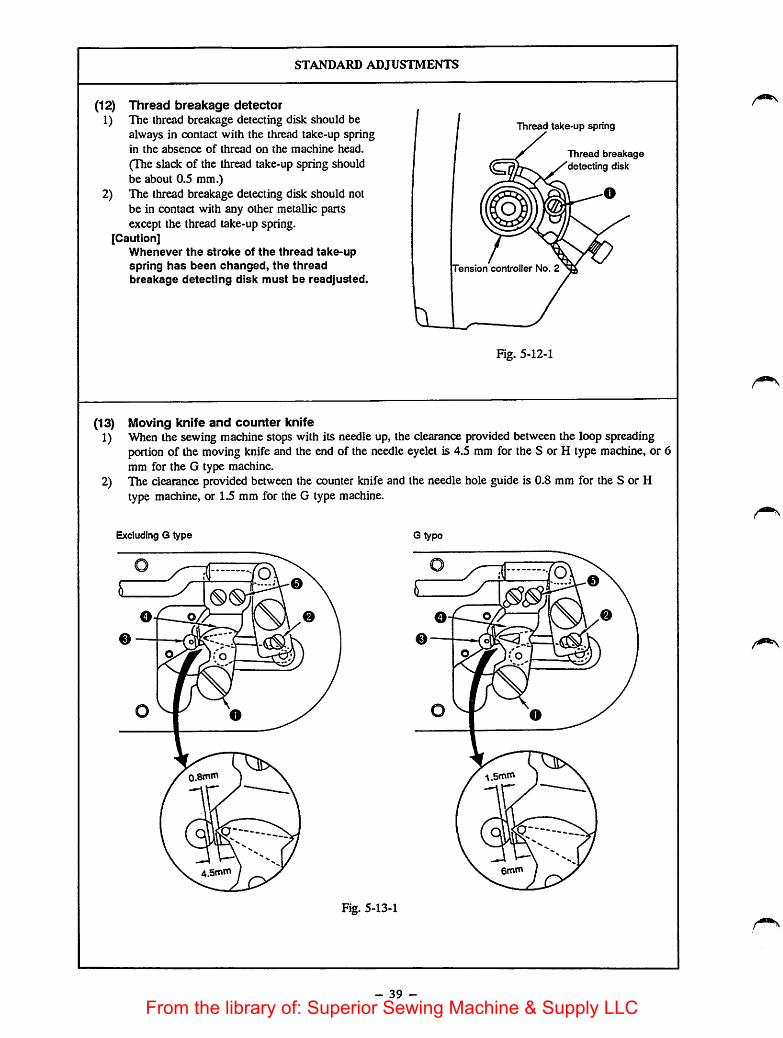
(12)1)
2)
Thread breakage detectorThe thread breakage detecting disk should bealways in contact with the thread take-up springin the absence of thread on the machine head.
(The slack of the thread take-up spring shouldbe about 0.5 mm.)The thread breakage detecting disk should notbe in contact with any other metallic partsexcept the thread take-up spring.
[Caution]Whenever the stroke of the thread take-upspring has been changed, the threadbreakage detecting disk must be readjusted.
Thread take-up spring
Tension controller No. 2
Kg. 5-12-1
Thread breakagedetecting disk
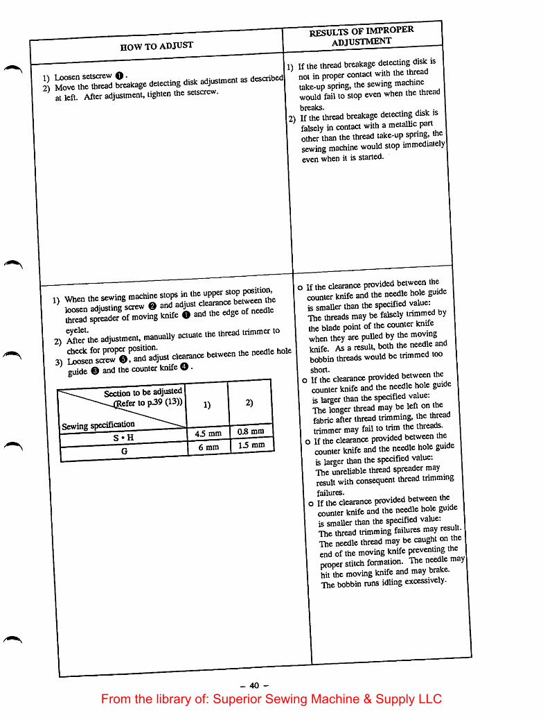
(13) Moving knife and counter knife1) When the sewing machine stops with its needle up, the clearance provided between the loop spreading
portion of the moving knife and the end of the needle eyelet is 4.5 mm for the S or H type machine, or 6mm for the G type machine.
2) The clearance provided between the counter knifeand the needle holeguide is 0.8 mm for the S or Htype machine, or 1.5 mm for the G type machine.
Excluding G type G type
%
Fig. 5-13-1
- 39 -
From the library of: Superior Sewing Machine & Supply LLC
now TO ADJUST
deleting dis. «.jus«nent as describedat left. After adjustment, tighten the setscrew.
1) When
S ofmov®hnife Oand the edge o£ needie2) 'intme adjustnient. manuaUy actuate the thread trininter to3) between the needle h^^^
guide O and the counter knife d •
Section to be adjustedleferto p39 (13)) 1) 2)
- 40 -
results of improperadjustment
11 If the thread breakage detecting disk isnot in proper contact with the threadtake-up spring, the sewing machinewould fail to stop even when the thread|)ro<iks
2) If the thread breakage detecting disk isfalsely in contact with ametallic partother than the thread take-up spnng, thesewing machine would stop immediatelyevenwhen it is started.
o Ifthe clearance provided between thecounter knife and the needle hole guideissmaUer than the specified value:The threads may be falsely tnmm^ bythe blade point of the counter knifewhen they are pulled by the movingknife. As a result, both the needle andbobbin threads would be trimmed tooshort. . ^
o Ifthe clearance provided between thecounter knife and the needle hole guideis larger than the specified value:The longer thread may be left on thefabric after thread trimming, the threadtrimmer may fail to trim the threads,
o Ifthe clearance provided between thecounter knife and the needle hole guideis larger than the specified value:The unreliable thread spreader mayresult with consequent thread trimmingfailures.
o Ifthe clearance provided between thecounter knife and the needle hole guideis smaller than the specified value:The thread trimming failures may result.The needle thread may be caught o" ®end of the moving knife preventing theproper stitch formation. Tht needle mayhit the moving knife and may brake.The bobbin runs idling excessively.
From the library of: Superior Sewing Machine & Supply LLC

(14)o
STANDARD ADJUSTMENTS
Height of the moving knife and the counter knifeThe thread trimmerwhich consists of a moving knife and counter knife should successfully cut a pair of#80 thread and another pair of #5 thread when the throat plate is removed and the thread rimming leveris manually actuated. (Fig. 5-13-1) (S, H type)The thread trimmer which consists of a moving knifeand counter knife should successfully cut a pair of#2 thread and another pair of #30 thread. (G type)
Moving knife
Throat plate
Fig. 5-14-1
Hinge screw
Washer
S, H type:0.3 to 0.4mm
G type:0.5 to 0.6mm
Counter knife Moving knife
Needle hole guide
Fig. 5-14-2
o Parallelism of the counter knife blade pointThe counter knife blade should be parallel to the throat plate mounting surface in order to cut a pair ofthreads (needle and bobbin threads) evenly.
'TTTTZ^
Fig. 5-14-3
The counterknife blade is paraUel to the throatplate mounting surface. The difference in levelbetween © and @ is within 5/100.
- 41 -
From the library of: Superior Sewing Machine & Supply LLC

now TO ADJUST
1) After the trial thread trimming.A. If the outer thread as observed from the moving knife pivot
cannot be trimmed, replace the washer with a thicker one.B. If the inner thread as observed from the moving knife pivot
cannot be trimmed, replace the washer with a thinner one.
2)
B
Part No. Name of part Thickness
B242328000A Moving knife washer 0.4 mm
B242328000B Moving knife washer 0.5 mm
B242328000C Moving knife washer 0.6 mm
B242328000D Moving knife washer 0.7 mm
Inner
Outer
Fig. 5-14-4
Moving knife
Moving knife pivot
If the above adjustment fails to correa the thread trimmingfailure.
A. If the height of the needle hole guide with respect to the counterknife blade is not within 0.3 to 0.4 for S or H type model ofsewing machine or0.5 to0.6 mm for G type one, pry portion O(Fig. 5-14-2) out using a screwdriver or the like to adjust theheight of the needle hole guidewith respect to the counter knifeblade to the correct height. (At this time, make sure that thebladepoint is in parallel to the throat plate mounting surface.)If the angle of the counter knife blade illustrated below is largerthan 90 degrees, cut the blade.
JCQJCSL
To be acute angle
Fig. 5-14-5
3) If the corrective measures described in 1)and 2)above fails tocorrect the trouble, replace the moving knife or the counterknife.
- 42 -
RESULTS OF IMPROPER
ADJUSTMENT
o Thread trimming failures may occur.
o If the height of the needle hole guidewith respect to the counter knife bladeexceeds 0.4 mm(S, H type) 0.6 mm (Gtype), both the needle thread and thebobbin thread will be cut too short.
Esp)ecially when sewing with a thinthread, the needle thread and bobbinthread will be frequently cut too short.
From the library of: Superior Sewing Machine & Supply LLC
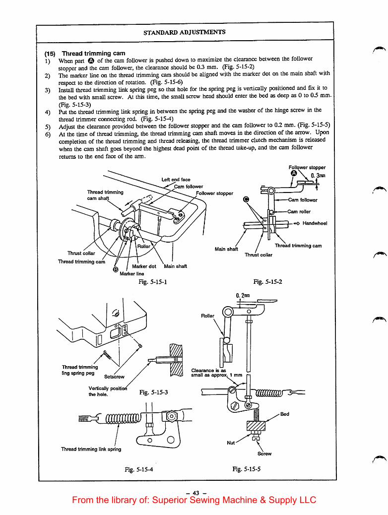
(15)
1)
2)
3)
4)
5)6)
STANDARD ADJUSTMENTS
Thread trimming camWhen part © ofthe cam follower is pushed down to maximize the clearance between the followerstopper and the cam follower, the clearance should be 0.3 mm. (Fig. 5-15-2)The marker line on the thread trimming cam should be aligned with the marker dot on the main shaft withrespect to the direction of rotation. (Fig. 5-15-6)Install thread trimming link spring peg so that hole for the spring peg isvertically positioned and fix it tothe bed with small screw. At this time, the small screw head should enter the bed as deep as 0 to 0.5 mm.(Fig. 5-15-3) ...Put the thread trimming link spring in between the spring peg and the washer of the hinge screw in thethread trimmer connecting rod. (Fig. 5-15-4)Adjust the clearance provided between the follower stopper and the cam follower to 0.2 mm. (Fig. 5-15-5)Atthe time of thread trimming, the thread trimming cam shaft moves in the direction of the arrow. Uponcompletion of the thread trimming and thread releasing, the thread trimmer clutch mechanism is releasedwhen the cam shaft goes beyond the highest dead point of the thread take-up, and the cam followerretums to the end face of the arm.
Thread trimmingcam shaft
Thrust collar
Thread trimming cam
ID
Thread tnmmingling spring peg
Vertically positionthe hole.
Thread trimming link spring
Left end face
Cam follower
Follower stopper
Roller
Marker dot Main shaft
Marker line
Fig. 5-15-1
Fig. 5-15-3
Main shaft
Ro er
Clearance is assmall as approx. 1 mm
0
Follower stopper
0. 3n*n
-Cam follower
Cam roller
Handwheel
Thread trimming cam
Thrust collar
Fig. 5-15-2
Fig. 5-15-4 Fig. 5-15-5
- 43 -
From the library of: Superior Sewing Machine & Supply LLC
HOW TO ADJUST
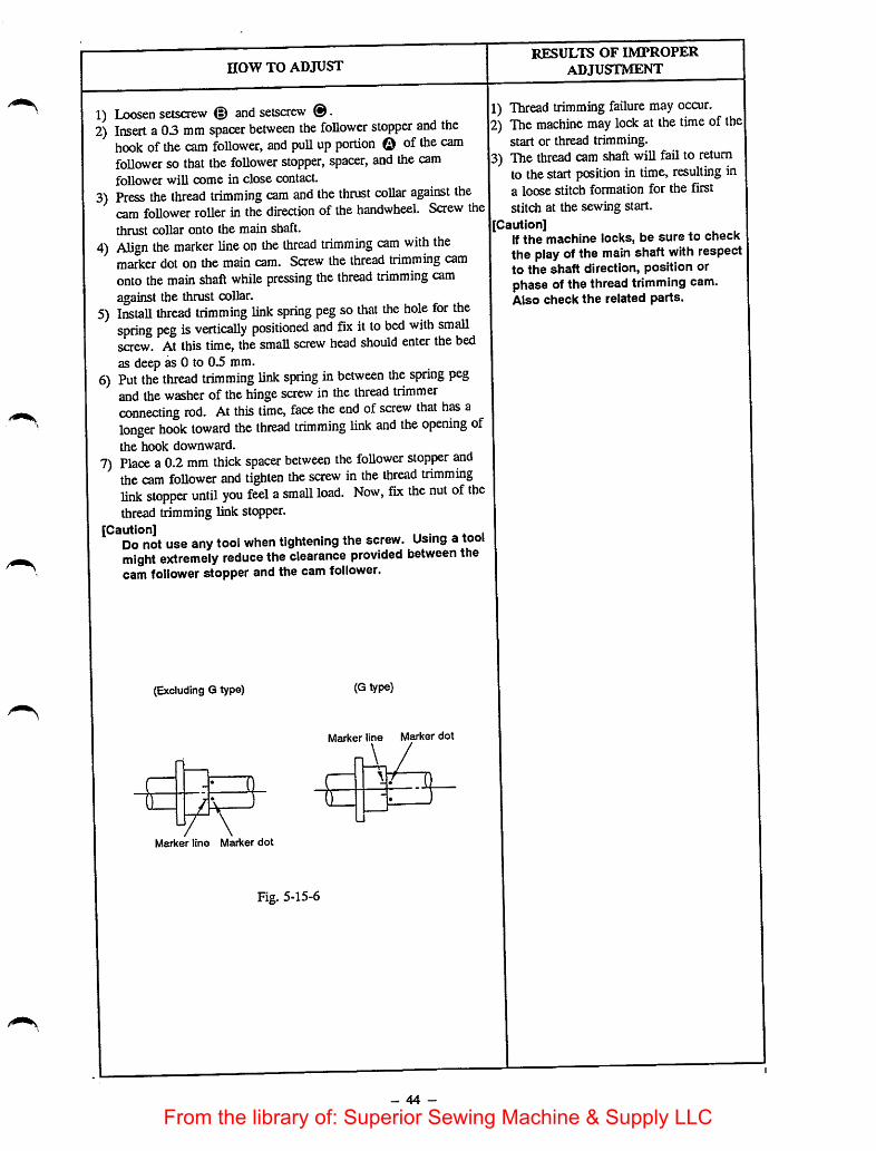
1) Loosen setscrew d) and setscrew @.2) Insert a0.3 mm spacer between the follower stopper and the
hook of the cam follower, and puU up portion © of thecamfollower so that the follower stopper, spacer, and the camfollower wiU come in close contact.
3) Press the thread trimming cam and the thrust collar against thecam follower roller in thedirection of the handwheel. Screw thethrust collar onto the main shaft.
4) Align the marker line on the thread trimming cam with themarker dot on the main cam. Screw the thread trimming camonto the main shaft while pressing the thread trimming camagainst the thrust collar.
5) Install thread trimming link spring peg so that the hole for thespring peg is vertically positioned and fix it to bed with smallscrew. At this time, the small screw head should enter the bedas deep as 0 to 0.5 mm.
6) Put the thread trimming link spring in between the spring pegand the washer of the hinge screw in the thread trimmerconnecting rod. At this time, face the end of screw that has alonger hook toward the thread trimming link and the opening ofthe hook downward.
7) Place a0.2 mm thick spacer between the follower stopper andthe cam follower and tighten the screw in the thread trimminglink stopper until you feel asmall load. Now, fix the nut of thethread trimming link stopper.
[Caution] ^ ,Do not useany tool when tightening the screw. Using a toolmight extremely reduce the clearance provided between thecam follower stopper and the cam follower.
(Excluding Q type)
( • <!0
Marker line Marker dot
Fig. 5-15-6
(G type)
Marker line Marker dot
\_ /
- 44 -
RESULTS OF IMPROPERADJUSTMENT
1) Thread trimming failure may occur.2) The machine may lock at the time ofthe
start or thread trimming.b) The thread cam shaft will fail to return
to thestart position in time, resulting ina loose stitch formation for the firststitch at the sewing start.
|[Caution]If the machine locks, be sure to checkthe play of the main shaft with respectto the shaft direction, position orphase of the thread trimming cam.Also check the related parts.
From the library of: Superior Sewing Machine & Supply LLC

STANDARD ADJUSTMENTS
(16) Thread trimming mounting base1) When the cam follower is pushed inward (in the direction of the arrow), clearance © between the edge
of the thread trimming cam and the tension release shaft arm should be 0.8 to 1.0 mm.2) Clearance © between the tension release arm driving shaft and the tension release arm should be 0.2 to
03 mm.
oTension releasearm driving shaft
Tension
release arm
©Cam follower
Thread
trimming cam
Hctndwheel
Main shaft
Fig. 5-16-1
Tension release •
shaft arm
EThread trimmer
mounting base
Thread trimmingcam shaft
Tension release
shaft arm
- 45 -
0.8 to 1.0mm
[Detailed figure ofsection ©
Tension
release shaft
Tension release
0.2 to 0.3mm
Detailed figure ofsection ©
From the library of: Superior Sewing Machine & Supply LLC

HOW TO ADJUST
1) Loosen setsaew 0. Move plate ® , which retains the tensionrelease shaft arm, forward or backward so that clearance ©between the edge of the thread trimming cam and the tensionrelease shaft arm becomes 0.8 to 1.0 mm. After adjustmait,securely tighten setscrew ©.
2) Loosen setscrew O • Movestopper @ forward or backward sothat clearance © between the tension release arm driving shaftand the tension release arm becomes 0.2 to 0.3 mm. After
adjustment, securely tighten setscrew O •
- 46 -
RESULTS OF IMPROPER
ADJUSTMENT
1) At the time of thread trimming, the topend of the tension release shaft arm will
come in contact with the end face of the
thread trimming cam, and the threadtrimming cam shaft will not be able totravel the normal stroke amount. As a
result, a machine lock will occur.2) After completion of thread trimming, the
thread trimming cam shaft will fail toreturn. As a result, a machine lock willoccur.
From the library of: Superior Sewing Machine & Supply LLC
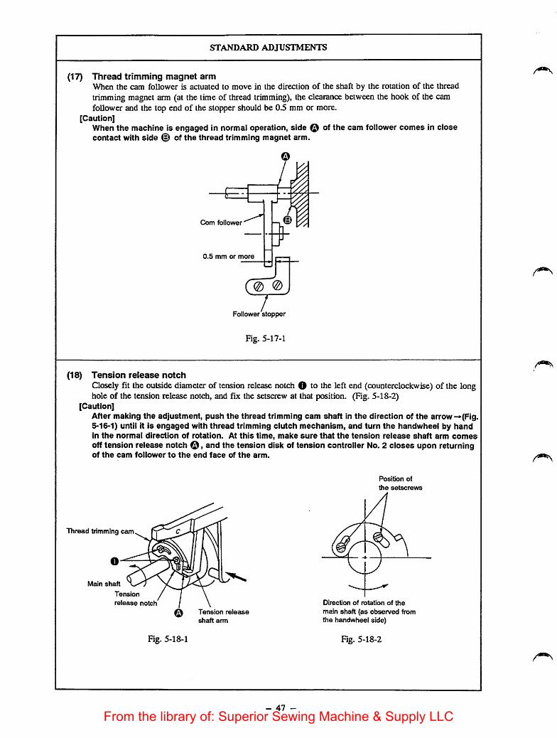
STANDARD ADJUSTMENTS
(17) Thread trimming magnet armWhen the cam follower is actuated to move in the direction of the shaft by the rotation of the threadtrimming magnet arm (at the time of thread trimming), the clearance between the hook of the camfollower and the top end of the stopper should be 0.5 mm or more.
[Caution]When the machine is engaged in normal operation, side Q of the cam follower comes in closecontact with side (§) of the thread trimming magnet arm.
Com follower
0,5 mm or more
0 @
Follower stopper
Fig. 5-17-1
(18) Tension release notchClosely fit the outside diameter of tension release notch O to the left end (counterclockwise) of the longhole of the tension release notch, and fix the setscrew at that position. (Fig. 5-18-2)
[Caution]After making the adjustment, push the thread trimming cam shaft in the direction of the arrow-»(Fig.5-16-1) until it is engaged with thread trimming clutch mechanism, and turn the handwheel by handin the normal direction of rotation. At this time, make sure that the tension release shaft arm comesoff tension release notch o , and the tension disk of tension controller No. 2 closes upon returningof the cam follower to the end face of the arm.
Thread trimming cam
Meun shaft
Tension
release notch
Fig. 5-18-1
Tension release
shaft arm
- 47 -
Position of
the setscrews
Direction of rotation of the
main shaft (as observed fromthe handwheel side)
Fig. 5-18-2
From the library of: Superior Sewing Machine & Supply LLC

HOW TO ADJUST
o Appropriately position the thread trimming magnet arm on thettorad trimming magnet aim shaft so that the specified clearaiiceis obtained between the cam toUower notch and the top end ofthe follower stopper.
o Refer to the "DISASSEMBLY/ASSEMBLY PROCEDURES(46)" on how to make the adjustment.
o Loosen setscrew O. and adjust therefetring to the "STANDARD ADJUSTMENTS (18). Aftermaking the adjustment, be sure to securely tighten setscrew O
- 48 -
results of improperadjustment
o Since the thread trimming clutchmechanism is not completely released,thread trimming and tension release willbe performed even when the main shaftrotates at high speed. As a result,damage, abrasion, loosening, or play inthe corresponding parts may occur.Since the cam follower comes in contactwith the follower stopper, the threadtrimming mechanism will not workproperly. As a result, a machine lockwill occur.
o The length ofthread remaining on theneedle after thread trimming wiU be tooshort and inconsistent,
o The thread may slip out from the needleeye at the sewing start.
From the library of: Superior Sewing Machine & Supply LLC

STANDARD ADJUSTMENTS
(19) Amount of release of the tension disksPressing the thread trimming cam shaft in the direction of the arrow (-»•), turn the handwheel by hand inthe normal direction of rotation until the tension releaseshaft arm rests on stepped portion © of thetension release notch. Now, the rising amount of the tension disk of the tension controller No. 2 shouldbe 0.6 to 0.8 mm for S or H type model of sewing machine or 0.8 to 1.0 mm for G type. (Fig. 5-16-1,Fig. 5-19-1, Fig. 5-19-2)
Fig. 5-19-1
S, H type:0.6 to 0.8mm
G type:0.8 to 1.0mm
- 49 -
Increase
Fig. 5-19-2
From the library of: Superior Sewing Machine & Supply LLC
now TO ADJUST
o Loosen thread tension arm setscrewO , and adjust the amountof releaseof the tension disks by moving thread tension arm 0referring to the "STANDARD ADJUSTMENTS (19)."
[Caution]o After making the adjustment, turn the handwheei by hand to
check that the thread tension disks keep opening untii thethread take-up reaches Hs highest dead point and the disksare completeiy ciosed. (The tension disks open at thehighest dead point.)
o if the tension disks ciose at the time of needle threading oractuating the machine, be sure to open the disks by sewingthe desired pattern to actuate the thread trimming, or bypressing the thread trimming cam shaft in the direction of thearrow (Fig. 5-16-1)to turn the handwheei in the normaidirection of rotation and start the thread trimming ciutchmechanism working so that the main shaft is brought to theupper resting position.
- 50 -
RESULTS OF IMPROPER
ADJUSTMENT
The length of thread remaining on theneedle after thread trimming will be tooshort and inconsistent.
A loose stitch formation may result.
From the library of: Superior Sewing Machine & Supply LLC
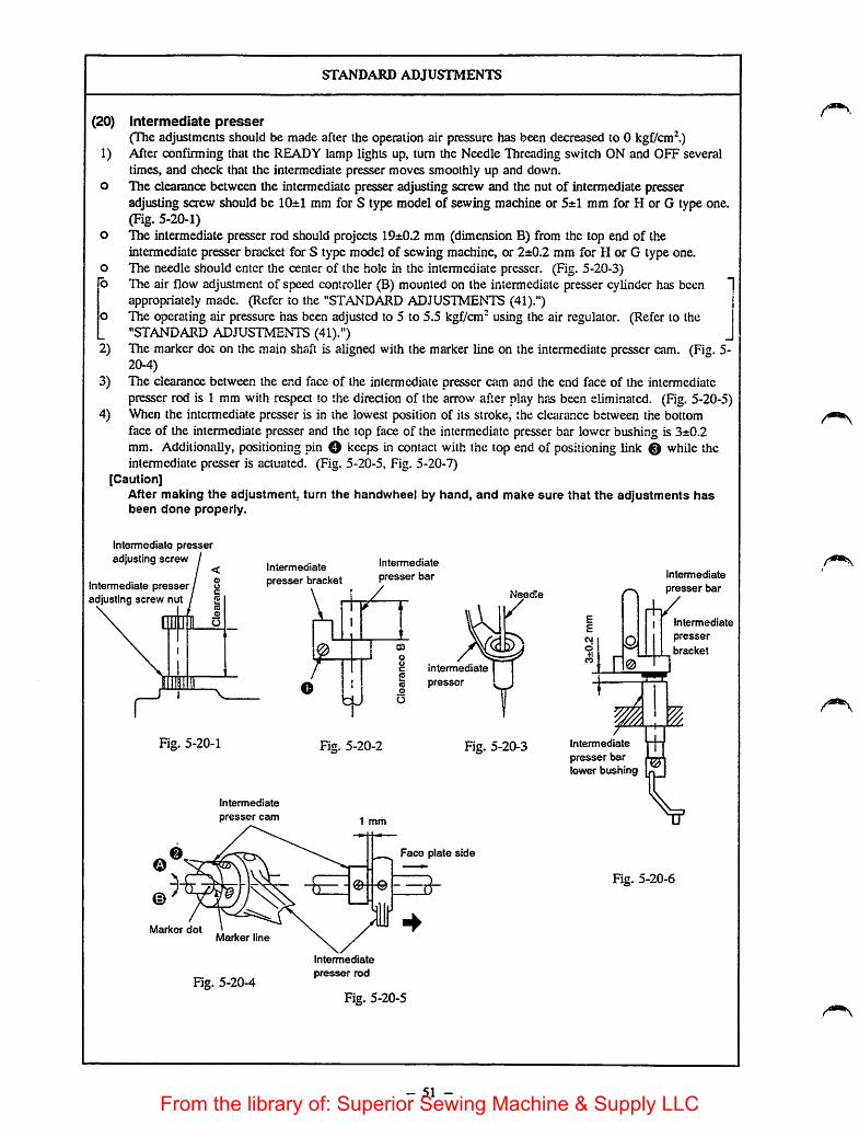
STANDARD ADJUSTMENTS
(20) Intermediate presser(The adjustments should be made after the operation air pressure has been decreased to 0 kgf/cm^)
1) After confirming that the READY lamp lights up, turn the Needle Threading switch ON and OFF severaltimes, and check that the intermediate presser moves smoothly up and down.
o The clearance between the intermediate presser adjusting screw and the nut of intermediate presseradjusting screw should be 10±1 mm for S type model of sewing machine or 5±1 mm for H or G type one.(Fig. 5-20-1)
o The intermediate presser rod should projects 19±0.2 mm (dimension B) from the top end of theintermediate presser bracket for S type model of sewing machine, or 2±0.2 mm for H or G type one.
o The needle should enter the center of the hole in the intermediate presser. (Fig. 5-20-3)b Hie air flow adjustment of speed controller (B) mounted on the intermediate presser cylinder has been
appropriately made. (Refer to the "STANDARD ADJUSTMENTS (41).")The operating air pressure has been adjusted to 5 to 5.5 kgf/cm" using the air regulator. (Refer to the"STANDARD ADJUSTMENTS (41).")
2) The marker dot on the main shaft is aligned with the marker line on the intermediate presser cam. (Fig. 5-20-4)
3) The clearance between the end face of the intermediate presser aim and the end face of the intermediatepresser rod is 1 mm with respect to the direction of the arrow after play has been eii.minated. (Fig. 5-20-5)
4) When the intermediate presser is in the lowest position of its stroke, the clearance between the bottomface of the intermediate presser and the top face of the intermediate presser bar lower bushing is 3±0.2mm. Additionally, positioning pin O keeps in contact with the top end of positioning link 0 while theintermediate presser is actuated. (Fig. 5-20-5, Fig. 5-20-7)
[Caution]After making the adjustment, turn the handwheei by hand, and make sure that the adjustments hasbeen done properly.
intermediate presseradjusting screw
Intermediate presser ^adjusting screw nut
Intermediate intermediatepresser bracket presser bar
intermediate
¥
Needle
Fig. 5-20-1 Fig. 5-20-2 Fig. 5-20-3
Intermediate
presser cam
Marker dotMarker line
Fig. 5-20-4
1 mm
Intermediate
presser rod
Face plate side
Fig. 5-20-5
- 51 -
Intermediate
presser barlower bushing
Intermediate
presser bar
rVIntermediate
presser
bracket
Fig. 5-20-6
From the library of: Superior Sewing Machine & Supply LLC

HOW TO ADJUST
n Adjust so that the clearance between the intermediate presseradjusting screw and the intermediate presser adjusting screw nutis 10±1 mm. (Fig. 5-20-1)
o Loosen intermediate presser bracket clamping screw O , Mdadjust the intermediate presser rod so that it projects 19±0.2 mmfrom the top end of the intermediate presser bracket for Stypemodel of sewing machine, or 2±0.2 mm for Hor Gtype one(Fig. 5-20-3) and that the needle point enters just the center otthe hole in the intermediate presser. Now, tighten intermediatepresser bracket clamping screw O. (Fig. 5-20-3)
2) Loosen intermediate presser cam setscrew ©'adjustment referring to the "STANDARD ADJUSTNffi^ (20-2)." Then tighten setsaew 0. For Sor Htype model ofsewing machine, align the marker line engraved on theintermediate presser cam with the marker dot engraved on themain shaft in terms of the normal direction of rotation. For Utype one, align the marker line with the marker dot on the mamshaft in terms of the reverse direction of rotation.
At the time ofdeUvery, the marker dot is aligned withthe marker line and the intermediate presser reachesthe lowest position of its stroke at the time when theneedle bar reaches the lowest position ofits stroke.Move the marker line in direction Q, and theintermediate presser will reach the lowest position ofits stroke earlier than the needle bar will reach itslowest position. On the other hand, move the markerline in direction ©, and the intermediate presser willreach the lowest position ofits stroke later than theneedle bar. By making this adjustment, the optimumUming can be obtained in accordance with the type ofmaterial to be sewn.
(Fig. 5-20-4)3) When making the adjustment described in step 2), adjust
intermediate presser cam and the end face intermediate presserITcWo the "^ANDARD ADJUSmEmS (20).3),
4) Loosen setscrew O with the needle bar at its lowest ea px)i(Fm 5-21-1), and make the adjustment described in the"STANDARD ADJUSTMENTS (20)-4)" by moving intermediatepresser oscillating shaft 0 with intermediatelink 0 closely pressed against positioning pin Q. (fig-
0
Fig. 5-20-7
- 52 -
results of improperadjustment
1) The intermediate presser may fail to goup after the completion ofa sewingcycle.
[Caution]Refer to the -RESULTS OF IMPROPERADJUSTMENT (8)."
o The intermediate presser may fail to goup after the completion ofasewingcycle. The round cornered section in thetop end of the intermediate presser barmay enter the intermediate presser barlower bushing while the intermediatepresser goes up, resulting in an oil leak.The needle may fail to enter the centerof the holeof the intermediate presser.As a result, a loose stitch formation wiUoccur, or the needle will come in contactjwith the intermediate presser.
2) Ifthe timing when the intermediatepresser reaches the lowest dead point ofits stroke is much earlier than the timing |when the needle bar reaches the lowestdead point ofits stroke, stitch skippingmay occur.
On theother hand, if the timing whenthe intermediate presser reaches thelowest dead point is much later than thetiming when the needle bar reaches thelowest dead point of its stroke, loosestitches may be fonned or theintermediate presser may be caught inthe overlapping sections ofthe material.
3) The intermediate presser cam may bepushed against the intermediate presserrod and the load torque may fluctuatewhen the mainshaft rotates in the•normal direction.
4) Abnormal noise may occur duringmachine operation.
[Caution]Abnormal noise will be producedespecially when Intermediate presserpositioning link 0 does notadequately come in contact withpositioning pin O. If the machine iskept tooperate in this condition, thecorresponding partsmight break.The specified vertical stroke will not beobtained. (Refer to the "STANDARDadjustments (21).")
From the library of: Superior Sewing Machine & Supply LLC
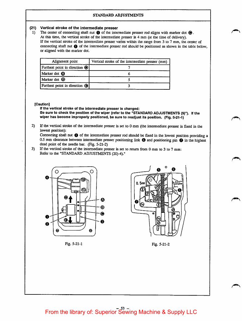
STANDARD ADJUSTMENTS
(21) Vertical stroke of the intermediate presser1) The center of connecting shaft nut O of the intermediate presser rod aligns with marker dot ®.
At this time, the vertical stroke of the intermediate presser is 4 mm (at the time of delivery).If thevertical stroke of the intermediate presser varies within the range from 3 to 7 mm, the center ofconnecting shaft nut O of the intermediate presser rod should be positioned as shown in the table below,or aligned with the marker dot.
Alignment point Vertical stroke of the intermediate presser (mm)
Furthest point in direction (fi) 7
Marker dot Q 6
Marker dot 5
Furthest point in direction © 3
[Caution]If the vertical stroke of the intermediate presser is changed:Be sure to check the position of the wiper (refer to the "STANDARD ADJUSTMENTS (9)"). Ifthewiper has become improperly positioned, be sure to readjust its position. (Fig.5-21-1)
2) If thevertical stroke of the intermediate presser is set to 0 mm (theintermediate presser is fixed in thelowest position):Connecting shaft nut O of the intermediate presser rod should be fixed in the lowest position providing a0.5 mm clearance between intermediate presser positioning link 0 and positioning pin © in thehighestdead point of the needle bar. (Fig. 5-21-2)
3) If the vertical stroke of the intermediate presser is set to return from 0 mm to 3 to 7 mm:Refer to the "STANDARD ADJUSTMENTS (20)-4)."
m
(D
Fig. 5-21-1 Fig. 5-21-2
- 53 -
From the library of: Superior Sewing Machine & Supply LLC

HOW TO ADJUST
1) Loosen connecting shaft nut O of the intermediate presser rodand move intermediate presser rod O in the direction of arrow
to inaease the stroke. Move the rod in the direction of
arrow to decrease the stroke. The standard vertical stroke of
the intermediate presser is 4 mm.Use marker dots ©, © and @ as the standard points to makethe adjustment. A 6 mm stroke is obtained when the center ofthe connecting shaft nut of the intermediate presser rod alignswith marker dot ©. A 5 mm stroke is obtained when thecenter of the connecting shaft nut of the intermediate presser rodaligns with marker dot ©. A 4 mm stroke is obtained when thecenter of the connecting shaft nut of the intermediate presser rodaligns with marker dot ©.
2) Fix connectingshaft nut O of the intermediatepresser rod inthe lowest position.Bring the needle bar to its highest dead point.Loosen setsaew O >and move intermediate presser oscillatingshaft 0 so that a 0.5 mm clearance is obtained betweenintermediate presserpositioning link 0 and positioning pin 0.Securely tighten setsaew O.
[Caution]Make sure that Intermediate presser positioning link 0 doesnot come in contact with positioning pin O, and theintermediate presser oscillating shaft 0 does not come incontact with intermediate presser spring 0, when thehandwheel is turned by hand to rotate the main shaft. If themachine operates under the condition that the link hitsagainst the pin and the oscillating shaft hits against thespring, breakage of the corresponding parts may result. (Fig.5-21-1, Fig. 5-21-2)
3) Refer to the "STANDARD ADJUSTMENTS (20)-4)."
- 54 -
RESULTS OF IMPROPER
ADJUSTMENT
1) The specified vertical stroke of theintermediate presser will not be o^ained.
In order to override the
overlapping section of thematerial, the vertical stroke ofthe intermediate presser shouldbe made greater. In this case,be sure to remember that
floppy material cannot beeasily fed if the vertical strokeis too great, resulting in stitchskipping.
2) The 0 mm vertical stroke of theintermediate presser will not be obtained
3) Refer to the "STANDARDADJUSTMENTS (20)-4)."
From the library of: Superior Sewing Machine & Supply LLC
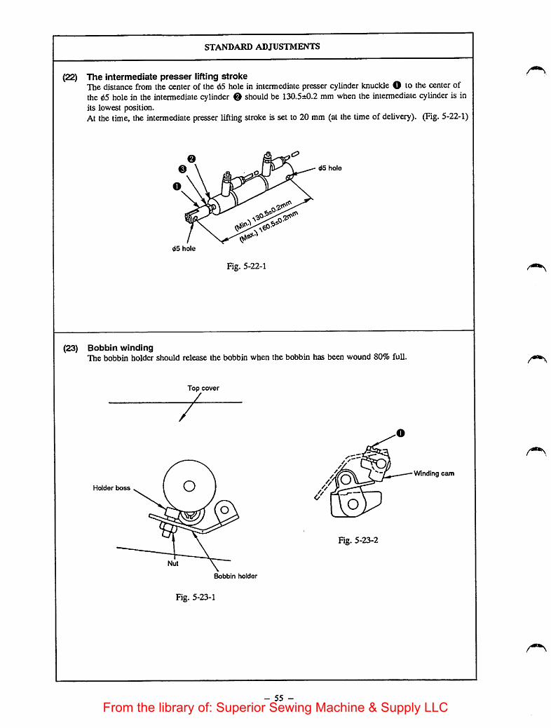
STANDARD ADJUSTMENTS
(22) The intermediate presser lifting strokeThedistance from the center of the d5 hole in intermediate presser cylinder knuckle O to the center ofthe d5 holein the intermediate cylinder 0 should be 130.5±0.2 mm when the intermediate cylinder is inits lowest position.At the time, the intermediate presser lifting stroke is set to 20 mm (at the time of delivery). (Fig. 5-22-1)
^5 hole
^5 hole
Fig. 5-22-1
(23) Bobbin windingThe bobbin holder should release the bobbin when the bobbin has been wound 80% full.
Top cover
Holder boss
Fig. 5-23-2
Bobbin holder
Fig. 5-23-1
- 55 -
Winding cam
From the library of: Superior Sewing Machine & Supply LLC

now TO ADJUST
o Loosen shaft nut @of intermediate presser cylinder O, andadjust the screwing depth of the intermediate cylinder knuckle Oreferring to the "STANDARD ADJUSTMENT (22)." Aftermaking the adjustment, securely tighten nut O and intermediatecylinder knuckle O • (Fig- 5-22-1)
1) Loosen the bobbin holder boss nut. Turn the bobbin holder bossso that the bobbin holder releases the bobbin which has beenwound 80% full. After making the adjustment, tighten t^ nut.
2) If the above adjustment does not work, loosen setscrew ff at t erear of the top cover, and adjust the angle of the bobbin holder.After making the adjustment, tighten setscrew O-
- 56 -
RESULTS OF IMPROPERadjustment
o When thedistance exceeds 130.5±0.2mm;
The intermediate presser lifting stroke isless than 20 mm.When the distance is less than 130.5±0.2mm:
Theintermediate presser will fail to belifted. The round cornered section in thetop end ofthe intermediate presser barmay enter the intermediate presser barlower bushing while the intermediatepresser goes up, resulting in an oil leak.
o An improper amount ofthread will bewound on the bobbin.
From the library of: Superior Sewing Machine & Supply LLC

STANDARD ADJUSTMENTS
(24) Bobbin winder driving wheel
Bobbin winder
driving wheel
Main shaft
Fig. 5-24-1
Face plate side
552:0.4mm
Bobbin winder driving wheelz
irnr
Fig. 5-24-2
(25) Height of the throat plate auxiliary cover
Throat plate
@
Throat plate auxiliary cover
0.3 mmor less
en
Fig. 5-25-1
Auxiliary coversupports (right)
Auxiliary cover
Fig. 5-25-2
- 57 -
Arm
]
From the library of: Superior Sewing Machine & Supply LLC

now TO ADJUST
o Loosen setscrews O »snd adjust so that a 55±0.4 mm distance isobtained from the end face of the bobbin winder driving wheeland the center of the top face of cover attaching tapO. Thentighten the setsaews so that the bobbin winder driving wheel isfixed at the position. (Fig. 5-24-1, Fig. 5-24-2)
Loosensix setscrews O (threesetscrews in both the left andright) of the throat plateauxiliary cover supports, and adjust sothat the throat plate auxiliary cover is positioned higher than thethroat plate by 0.3 mm or less. Then tighten the setscrews.At this time, be careful to adjust the points marked by theportion ( @) (Fig. 5-25-1).(Fig. 5-25-1, Fig. 5-25-2)
- 58 -
RESULTS OF IMPROPER
ADJUSTMENT
o The bobbin may fail to spin or thebobbin holder may fail to actuate, evenif the bobbin is set on the bobbin
winder.
The feed plate will be caught by thestepped partsformed by the throat plateand the throat plate auxiliary coverresulting in a deformed pattern.The feed plate may bend.
From the library of: Superior Sewing Machine & Supply LLC

STANDARD ADJUSTMENTS
(26) Height of the work clamp foot slider
3.5»0.2mm
Presser plate Work clamp foot slider
/ /
Fig. 5-26-1
Feed bracket
O Work clamp foot slider base
(27) Holding force of the feeding frame ball catcher (when the optional feeding frame arm isused)The feeding frame support shaft is released from the feeding frame ball catcher when the feeding framesupport shaft base is pressed in the direction of thearrow with 3.5 to 4.0 kgf/cm^ load. (Fig. 5-27-1)
Feeding framesupport shaft
Feeding frame•y/ ball catcher
Feeding framesupport shaft base
Holding forceadjusting screwO
Fig. 5-27-1
(28) Vertical stroke of the work clamp footThe distance from the center of the 65 hole of the work clamp foot cylinder knuckle to the center of the65 hole of the cylinder knuckle should be 120.5±0.3 mm, then the shaft of the work clamp foot cylinderis in its lowest position. (Fig. 5-28-1)
IgO.&sO.Smm
D
Cylinder knuckle
Hose elbow
Fig. 5-28-1
- 59 -
From the library of: Superior Sewing Machine & Supply LLC

HOW TO ADJUSTRESULTS OF IMPROPER
adjustment
o Loosen setscrew O >̂ nd adjust so that a 3.5±0.2 mm clearanceis obtained between the presser plate and the work clamp footslider base by turning the work clamp foot slider base using awrench. Then tighten setsaew O.
o The pattern may be deformed.
o Refer to the "STANDARD ADJUSTMENT (27)," and adjust theholding force of the feeding frame ball catcher using holdingforce adjusting screw O-Turn holding force adjusting saew O clockwise, and theholding force will be increased. Turn the screw in the reversedirection, and the holding force will be deaeased. Be sure toadjust the holding force of the two feeding frame ball catchersmounted one each on both the rightand left side.
Loosen nut O of the work clamp cylinder shaft and adjust thescrewing depth ofthe cylinder knuckle with regard to the shaftreferring to the "STANDARD ADJUSTMENTS (28).After adjustment, be sure to securely fix the cylinder knuckleusing nut O* Equally adjust the two cylinders mounted oneeach on the left and right.
- 60 -
o If the holding force is too strong:The feeding frame cannot be installed orremoved.
o If the holding force is inadequate:When the feeding frame goesup at thesewing end, the feeding frame may dropThe pattern may be deformed.
If the distance exceeds 120.5±0.3 mm:The feedingframe may fail to go up ashigh as 30 mm.If the distance is less than 120.5±03mm:
The feeding frame may fail to comedown to the lowest position of its strokeAs a result, the workpiece may slip fromthe correct position since it may notbeheld securely.
From the library of: Superior Sewing Machine & Supply LLC

STANDARD ADJUSTMENTS
(29) Adjusting the top cover of X-travel unit and travel unit cover joint
X-Y table
Top cover asm.of X-travel unit
Fig. 5-29-1
Travel unit cover joint
Travel unit cover
presser mounting plate
Fig. 5-29-2
(30) X guide shaft supportWhen the feed bracket is moved laterally by hand, both ends of the X guide shaft support should notmove up and down.
Fig. 5-30-1
- 61 -
Y movable shaft
© © \Y movable shaft setscrew
From the library of: Superior Sewing Machine & Supply LLC

now TO ADJUST
o Put the top cover asm. of the X-travel unit between the X-Ytable and the travel unit cover joint and fit the bored portion onthe rearof the travel unit coverjoint to drilled hole O.
o Fix the top cover of the X-travel unit using the setscrews. Twoof these setscrews are commonly used to fix the travel unit coverjoint.
[Caution]After the adjustment, move the feed bracket back and forth aswell as to the right and left to confirm that the top cover Isnot pushed against feed bracket auxiliary cover, throat plateauxiliary cover and the travel unit cover (A). (Figures 5-29-1,-29-2 and -53-1)
o Closely fitting the travel cover presser against plane A, fix thetravel cover presser mounting presser on the feed bracket withthe setscrews. (Figures 5-29-1 and -2)
Move the feed bracket toward the handwheel (in the direction ofthe arrow) by hand until it will go no further.Loosen the Y movable shaft setscrews so that side A of the Ymovable shaft comes in full contact with side B of the X guideshaftsupport. Then tighten theY movable shaft setscrews.
- 62 -
RESULTS OF IMPROPER
ADJUSTMENT
o The corresponding parts may becomedamaged.
o The pattern may be deformed.
From the library of: Superior Sewing Machine & Supply LLC

STANDARD ADJUSTMENTS
(31) X-direction feed belt tensionMove the feed bracket as far to the left as possible. Adjust so that the X-direction feed belt slackens by1.6 to 1.8 mm when a load of 500 g is applied to the middle (shown by the arrow) of the right belt.
1. 6~1. Sirni
Fig. 5-31-1
(32) Y motor mounting base
y movable shaft
Fig. 5-32-1
- 63 -
Y motor mountingbase (asm.)
Y motor mounting base(asm.) setscrews OSS7151210SP - 4 PCS.
From the library of: Superior Sewing Machine & Supply LLC

now TO ADJUST
o Loosen screw O and nut 0 • Turn tension adjusting screw 0to adjust the belt tension. Tighten saew O and nut 0 .
[Caution]Tightening screw O wili affect the belt tension, so check thebelt slackagain aftertightening screwO • (Fig- 5-31-1)
(1) Move the Y-travel shaft back and forth until a position atwhich themoving torque is maximized is reached.
(2) Adjust the height of the Ymotor base so that astartingtorque of 2.5 to 4kg is developed when pressing the Y-travel Ishaft is pressed, in the aforementioned state (1), in thedirection of the arrow
[Caution] * .t. i1. Do not connect the connector of thestepping motor to the|
machine.
2. Adjust theYmotor base with the presser plate removed.3. This adjustment is not necessaryinthe regular
maintenance. So, never loosen the screw In the Y motorbase (asm.).
- 64 -
RESULTS OF IMPROPERADJUSTMENT
o The pattern may be deformed.
A loud noise will be produced alongwith the feed in the Y-direaion. Thepattern may be deformed, or thecorresponding partsmay becomedamaged.
From the library of: Superior Sewing Machine & Supply LLC
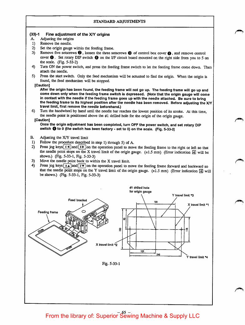
STANDARD ADJUSTMENTS
(33)-1 Fine adjustment of the XA^ originsA. Adjusting the origins1) Remove the needle.2) Set the origin gauge within the feeding frame.3) Remove five setscrews 0, loosen the three setscrews @ of control box cover Q >snd remove control
cover O. Set rotary DIP switch O on the I/Fcircuit board mounted on the right side from you to 5 onthe scale. (Fig. 5-33-2)
4) Turn ON the powerswitch, and press the feeding frame switch to let the feeding frame come down. Thenattach the needle.
5) Press the start switch. Only the feed mechanism will be actuated to find the origin. When theorigin isfound, the feed mechanism will be stopped.
[Caution]After the origin has been found, the feeding frame will not go up. The feeding frame will go up andcome down only when the feeding frame switch is depressed. (Note that the origin gauge will comein contact with the needle if the feeding frame goes up with the needle attached. Be sure to bringthe feeding frame to its highest position after the needle has been removed. Before adjusting the X/Ytravel limit, first remove the needle beforehand.)
6) Turn the handwheel by hand until the needle bar reaches the lowest position of its stroke. At this time,the needle point is positioned above the 01 drilled holefor the origin of the origin gauge.
[Caution]Once the originadjustment has been completed, turn OFF the powerswitch, and set rotary DIPswitch O to 0 (the switch has beenfactory - set to 0)on the scale. (Fig. 5-33-2}
B.
1)2)
3)4)
Adjusting the X/Y travel limitFollow the procedure described in step 1) through 5) of A.Press jogkeys! 4-< [and! 6^ [on the operation panel tomove the feeding frame to the right or left so thatthe needle point stops on the X travel limit of the origin gauge. (±1.5 mm) (Error indication O will beshown.) (Fig. 5-33-1, Fig. 5-33-3)Move the needle point back to within the X travel limit.Press jog keys I8a |and| 2y jon the operation panel to move the feeding frame forward and backward sothat the needle point stops on the Y travel limit of theorigin gauge. (±1.5 mm) (Error indication [4] willbe shown.) (Fig. 5-33-1, Fig. 5-33-3)
Feed bracket
Feeding frame
X travel limit *2
Fig. 5-33-1
drilled hole
for origin gauge
- 65 -
Y travel limit *3
X travel limit *1
Y travel limit *4
From the library of: Superior Sewing Machine & Supply LLC

now TO ADJUST
DOOOO
BO.
Fig. 5-33-2
The positions of theX/Y origin and theX/Y travel limit
sensor will be shown
on the display of theoperation panel eisillustrated in Fig.5-33-3.
X-dlrectlon
D: Travel limit *2
E: OriginF; Travel limit *1
n
Fig. 5-33-3
•JUKIAMS
8 -9
••ipsn nsQIB
Y-directlon
G; Travel limit *4
H; OriginI: Travel limit *3
- 66 -
RESULTS OF IMPROPER
ADJUSTMENT
From the library of: Superior Sewing Machine & Supply LLC

STANDARD ADJUSTMENTS
(33)-2 X/Y origins and travel limit sensors1) Remove the needle.
Remove setscrews O the feeding frame arm.Attach the sensor adjusting gauge taking the position of the feeding frame arm guide pin as reference.(The related dimensions for the sensor adjusting gauge are shown in Fig. 5-33-5.)Check the positions of origin and the XfY travel limit referring to the "STANDARD ADJUSTMENTS(33)-l Fine adjustment of the X/Y origin". (See Fig. 5-33-5)
2)3)
4)
Feeding frame
Work clamp
Sensor adjusting gauge
Fig. 5-33-4
- 67 -From the library of: Superior Sewing Machine & Supply LLC
now TO ADJUST
A. Adjusting the X-axis origin and travel limit sensor1) Remove the feed bracket auxiliary covers (left and right), and
feed bracket cover.
2) Make the adjustments described in steps 1), 3) and 4) of the"STANDARD ADJUSTMENT (33)-l, A."
3) Press jog kevsiTTi.rsrj,' SAjand | 2t |on the operation panel tomove the feeding frame. Align the needle point with the <60.5drilled hole for origin ofthe origin gauge. (Fig. 5-33-5)
4) Loosen setscrews O , and move Xsensor attaching plate asm. tothe left or right untU display (B) showing the Xorigin changesfrom 1 to 0. Immediately after the display has changed, tightensetscrews O • (Fig- 5-33-3, Fig. 5-33-5)
5) Press jog keyIsV |on the operation panel to move the feedingframe so that the needle point aligns with marker line Voftravel limit *1. (Fig. 5-33-6, Fig. 5-33-3)
6) Loosen setscrews 0» and move X-axis right travel limit sensorattaching plate asm. to the left or right until display (F) showingthe travel limit *1 changes from 1 to 0. Immediately after thedisplay has changed, tighten setscrews O- (Fig- 5-33-3, Fig. 5-33-6) , ^ ..
7) Press jog keyl 4-< |on the operation panel to move the leeomgframe so that the needle point aligns with marker line Voftravel limit *2. (Fig. 5-33-3)
8) Loosen setscrews O» and move X-axis left travel limit sensorattaching plate asm. to the left or right until display (D) showingthe travel limit *2 changes from 1 to 0. Immediately after thedisplay has changed, tighten setscrews O•
^^\fter^making the adjustments, make sure that the X-axis slitdisk enters the center ofthe clearance between the sensorphoto-couplers and that the sift disk overlaps the top end ofthe sensor photo-coupler by 5mm or more, when the X-^isslit disk passes through the three X-axIs sensors. (Fig. 5-337)If they do not, adjust the clearance between the slit disk andthe photo-coupler referring to "C. Clearance between the slitdisk and the photo-coupler." Note that you should adjust theoverlapping depth simultaneously with step 4), 6) and 8)
- 68 -
RESULTS OF IMPROPERadjustment
o If the origin has not been properlyadjusted:The origin for inputting a pattern fails tojalign with theorigin for sewing thepattern.
o If the travel limit has not been properlyadjusted:The sewing area may be narrower. Thestepping motor fails tostop even whenthe medianical travel limit has beenreached. As a result, an abnormal noisemay be produced.
[Caution!If the machine Is operated under thecondition mentioned above, the feedmechanism components mightbecome damaged. Never operate themachine until the proper adjustmentshave been completed.
From the library of: Superior Sewing Machine & Supply LLC

STANDARD ADJUSTMENTS
5) Adjust the sensor adjusting gauge to obtain the following dimensions.
58 58
Marker line for Y-axis
travel limit *41
/ /Marker line for Y-axis
travel limit *3
Marker line for X-axis
travel limit *2
8.5
d7
A.
46
^0.5 drilled hole
for the origin i
b
1
Marker line for X-axis
travel limit *1
136
Fig. 5-33-5
- 69 -
d4
dS
cnT cnfoi in ID
d4
From the library of: Superior Sewing Machine & Supply LLC

HOW TO ADJUST
B. Adjusting the Y-axis origin and travel limit9) Remove the Y sensor cover. (Fig. 5-33-8)
Follow the same procedure described in steps 2) and 3).Loosen setscrews O > move the Y sensor attaching plateto the left or right until display (H) showing the Y originchanges from 1 to 0. Immediately after the display haschanged, tighten setscrews O • (Fig. 5-33-3, Fig. 5-33-9)Press jog key Q on the operation panel to move thefeeding frame until display (I) showing the travel limit *3changes from 1 to 0. Immediately after the display haschanged, stop the feeding frame. (Fig. 5-33-3)Make sure that a gap between the sensor and the needle tip is1.5 mm or less in terms of the marker line V of travel limit
•3.
With regard to display (G) showing travel limit *4, press jogkey and make the adjustment referring to the proceduredescribed in step 12).With regard to marker line V of travel limit *4, make surethat the specified distance is obtained referring the proceduredescribed in step 13).
[Caution]After making the adjustments, make sure that the Y-axis slitdisk enters the center of the clearance between the sensorphoto-couplers and that the slit disk overlaps the top end ofthe sensor photo-coupler by 5 mm or more, when the Y-axisslit disk passes through the two Y-axIs sensors. If they donot, adjust the clearance between the slit disk and the photo-coupler referring to "0. Clearance between the slit disk andthe photo-coupler.'
10)
11)
12)
13)
14)
15)
- 70 -
RESULTS OF IMPROPER
ADJUSTMENT
From the library of: Superior Sewing Machine & Supply LLC

STANDARD ADJUSTMENTS
X-axis sensor attaching plate
X-axis
/EE
TT
X-eixis righttravel limit sensor
X-axis sensors
TTTT E n-TT 'I M.
X-axis
siadisk Vr-rA
\ ^\ X-origin sensor ^ \
I • I X"3—=== 3 trav
!-axis left —
travel limit sensor
-O-
Pbo
Fig. 5-33-6
Y-etxis sensor cover
Fig. 5-33-8
-o-o o
o o
u-
7X-8ucis slit disk
Fig. 5-33-7
Y-originY-axis travel
limit sensor
\
Y-axis sensor
attaching plate
Y-ongin
L_58±0. 2irm_JFig. 5-33-9
C. Adjusting the clearance between the slit diskand the photo-coupler
I I®
Sensor
/
Fig. 5-33-10
Y-originsensors
Slit disk
Y-axis travel
limit sensor
- 71 -
Y-axis s It disk
Y slit fixing plate
Fig. 5-33-11
From the library of: Superior Sewing Machine & Supply LLC

now TO ADJUST
o Adjusting theX sensorRespectively position the Xtravel sensors (ngh) ^ ^tot they work when the feeding frame moves to the iigW andleft by 92 mm. Tlien, fix them with screws O. (Figures5-33-10 and -11)
° If?he Ysm plate and photo-coupler do not overlap as deep ^5r^,^ or morcfloosen s^ws @and adjust the Yslit fnttng plate.After the adjustment, fix it with the screws.
Adiust the Yorigin using screws 0. (Figures 5-33-9 and -11)Adjusting the origin automaticaUy determines the position of theY travel limit sensor.
""'Ssure that the am disk does not come in contaet with thephoto-coupler.
- 72 -
RESULTS OF IMPROPERadjustment
o The sensors fail to detect the X/Y origin jor travel limits, resulting in the sameproblems caused by the improperadjustment of the origin or travel limits,
o Since theslit disk may come in contactwith the photo-coupler, thecorresponding parts could becomebroken or damaged.
From the library of: Superior Sewing Machine & Supply LLC

STANDARD ADJUSTMENTS
(34) Shuttle race ringIf the blade point of the shuttle becomes badly worn out, remove the shuttle race ring and check whetheror not the hatched section illustrated has the dimensions of 0.2 x 8 mm.
(35) Eliminating play from the main shaft
Main shaft
Bushing ' ' Thrustcollar Thread trimming cam
Fig. 5-35-1
Screwdriver
Thrust collar
4
Binm
0.2™i
Fig. 5-34-1
Handwheel
(36) Belt tensionThe middle of the belt should slacken by 10 mm when section A of the belt is subjected to 1 kg load.
Fig. 5-36-1
- 73 -From the library of: Superior Sewing Machine & Supply LLC

HOW TO ADJUST
o If the hatched section does not have the dimensions of 0.2 mmx
8 mm, correct it using an oilstone.
o Drawing the handwheel in the direction of the arrow, fix thethrust collar while pressing it against the intermediate bushing.
o Loosen nuts O, and move the motor up or down to change theinstallation position of the motor.
[Caution]Be sure to remove or Install the belt with the Intermediate
presser removed.
- 74 -
RESULTS OF IMPROPER
ADJUSTMENT
o The vibration of the belt may increase,resulting in the sewing machinevibrating more greatly.
[Caution]If the vibration of the belt Is excessive,the belt may come In contact with thebelt cover. As a result, the belt maybecome damaged. Be sure to checkthe belt tension before operating thesewing machine.
From the library of: Superior Sewing Machine & Supply LLC

STANDARD ADJUSTMENTS
(37) Raising the sewing machine headWhen doing maintenance work on the shuttle driver shaft components, raise the sewing machine headaccording to the following procedure.
Fig. 5-37-1
- 75 -
From the library of: Superior Sewing Machine & Supply LLC
now TO ADJUST
o To raise the sewing machine, attach grip O supplied with thesewing machine and raise the sewing machine in the direction ofthe arrow.
Be sure to use stopper © when working with the sewingmachine raised.
^ Make^sure that stopper ©is securely locked. It will be verydangerous If thestopper is not locked properly
- 76 -
RESULTS OF IMPROPERadjustment
From the library of: Superior Sewing Machine & Supply LLC
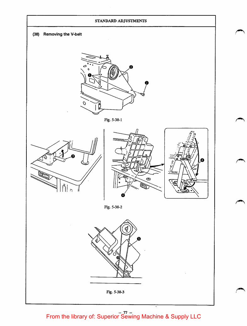
STANDARD ADJUSTMENTS
(38) Removing the V-belt
Fig. 5-38-1
Fig. 5-38-2
Fig. 5-38-3
77 -
From the library of: Superior Sewing Machine & Supply LLC

now TO ADJUST
1) Remove screw O and remove belt cover 0. (Fig. 5-38-1)2) Attach grip 0 supplied with the machine in position, and raise
it in the direction of the arrow. At this time, be sure to usestopper O. (Fig. 5-38-2)
3) Remove V-belt ©. (Fig. 5-38-3)
- 78 -
RESULTS OF IMPROPER
ADJUSTMENT
From the library of: Superior Sewing Machine & Supply LLC

STANDARD ADJUSTMENTS
(39) Holding force of the plastic feeding frame blank plateAdjust the fixing position of the plastic feeding frameblank plate.
Plastic feedingframe blank stud
Plastic blank
Feeding frame
Fig. 5-39-1
Plastic feedingframe blank stud
Plastic blank holder
Close contact
F5g. 5-39-2
- 79 -
Ball catcher
From the library of: Superior Sewing Machine & Supply LLC

HOW TO ADJUST
1) Loosen saew O• Attach the plastic blank to the feeding frameand fix it properly, (Fig. 5-39-1, Fig. 5-39-2)
2) Adjust the position of the plastic feeding frame blank so that theplastic feeding frame blank comes in close contact with theplastic feeding frame blank stud, while pressing the plasticfeeding frame blank in the direction A. Then tighten screws O•(Fig. 5-39-2)
- 80 -
RESULTS OF IMPROPERadjustment
o The plastic feeding frame blank mayeasily drop from the feeding frame. Theplastic feeding frame blank may fail tobe set to the feeding frame
From the library of: Superior Sewing Machine & Supply LLC

STANDARD ADJUSTMENTS
(40) Feed plate
Feed plate B2556215000(Feed plate for inverting: B2556215A00)
©
Fig. 5-40-1
- 81 -
0 Positioning pin
0 Setscrew (2pcs.) SM6060802TPWasher (2 PCS.) WP0611626SP
From the library of: Superior Sewing Machine & Supply LLC
now TO ADJUST
1) Fit positioning pin O ^feed plate with two screws 0 . This determines the position ofthe feed plate.If you want to change the position of the feed plate, use the feedplate with positioning pin O removed.
- 82 -
RESULTS OF IMPROPER
ADJUSTMENT
o The workpiece may slip during sewing.
From the library of: Superior Sewing Machine & Supply LLC

(41)1)
2)
3)
4)
5)
STANDARD ADJUSTMENTS
Adjusting the pneumatic componentsConnect quick-coupling joint O , and open air cock 0 . At this time, air pressure gauge 0 shouldindicate 5 to 5.5 kgf/cm^ (0.5 to 0.55 MPa). (Fig. 5041-1)If the value indicated on air pressure gauge O is lower than 4 kgf/cm" (0.4 MPa), error indicationwill be given, and the machine will stop. (Fig. 5-41-1)The air pressure on the work clamp cylinder retracting side has been reduced to 1 to 1.5 kgf/cm" (0.1 to0.15 MPa) and the feeding frame can be lowered by hand. (Fig. 5-41-2)The needle knob of speed controller (for controlling the work clamp cylinder) is fixed by the nut at theposition where the knob is turned in the reverse direaion by one revolution after it has been securelytightened. (Fig. 5-41-3)The needle knob of speed controller (for controlling the intermediate prcsser cylinder) is fixed by the nutat the position where the knob is turned in the reverse direction by five revolutions after it has beensecurely lightened. (Fig. 5-41-4)
0 0 o
Fig. 5-41-1
1~1.5kgf/cia 0
Fig. 5-41-2
For controlling the workcylinder (right)
Solenoid
valves (asm.)
oI Input
jN'umbeq ^
UoM 1 Function
Intermediate pressercylinder (asm.)
For controlling the workclamp cylinder (left)
- 83 -
From the library of: Superior Sewing Machine & Supply LLC
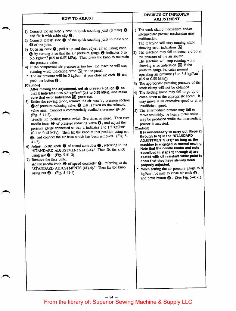
HOW TO ADJUST
1) Connect the air supply hose to quick-coupling joint (female) Oand fix it with cable clip ®.
2) Connect female side O ofthe quick-coupling joint to male sideO of the joint.
3) Open air cock ©, pull it up and then adjust air adjusting knob© by turning itso that the air pressure gauge © indicates 5 to5.5 kgf/cm" (0.5 to 035 MPa). Then press the Jcnob to maintainthe pressure value.
4) Ifthe compressed air pressure is too low, the machine will stoprunning while indicating error 0 on the panel.
* The air pressure will be 0kgf/cm" if you close air cock © andpush thebutton © .
[Caution]After making the adjustment, set airpressure gauge © sothat it indicates 5 to 5.5 kgf/cm® (0.5 to 0.55 MPa), and makesure that error indication {Aj goes out.
5) Under the sewing mode, remove the air hose by pressing section© ofpressure reducing valve O that isfixed on the solenoidvalve asm. Connect a commercially available pressure gauge.(Fig. 5-41-2)Treadle the feeding frame switch five times or more. Then turnneedle knob © of pressure reducing valve ©, and adjust thepressure gauge connected so that it indicjites 1 to 1.5 kgf/cm(0.1 to 0.15 MPa). Then fix the knob at that position using nut©, and connect the air hose which has been removed. (Fig. 5-41-2)
6) Adjust needle knob © of speed controller © , referring to the"STANDARD ADJUSTMENTS (41)-4)." Thenfix the knobusing nut ©. (Fig. 5-41-3)
7) Remove the face plate.Adjust needle knob © of speed controller ©, referring to the"STANDARD ADJUSTMENTS (41)-4)." Then fix the knobusing nut ©. (Fig. 5-41-4)
- 84 -
RESULTS OF IMPROPERADJUSTMENT
1) The work clamp mechanism and/orintermediate presser mechanism maymalfunction.
The machine will stop runningwhileshowing error indication El•
12) The machine may fail to detect adrop injthe pressure of the air source.The machine will stop running whileshowing error indication Elpressure gauge indicates normaloperating air pressure (5 to 5.5 kgf/cm"(0.5 to 0.55 MPa)).
13) The appropriate pressing pressure of thework clamp win notbe obtained.
14) The feeding frame may fail to go up orcome down at the appropriate speed. Itmay move at an excessive speed or at an|insufficient speed.
15) The intermediate presser may fail tomove smoothly. A heavy metal noisemay be produced while the intermediatepresser is actuated.
I[Caution]It is unnecessary to carry out Steps 2)through to 5) in the "STANDARDADJUSTMENTS (41)" as long as themachine is engaged in normal sewing, jNote that the needle knobs and nutsdescribed in steps 3) through 4) arecoated with oil resistant white paint toshow that they have already beenproperly adjusted.When setting the air pressure gauge to 01kgf/cm^ be sure to close air cock ©,and press button ©. (See Fig. 5-41-1)
From the library of: Superior Sewing Machine & Supply LLC
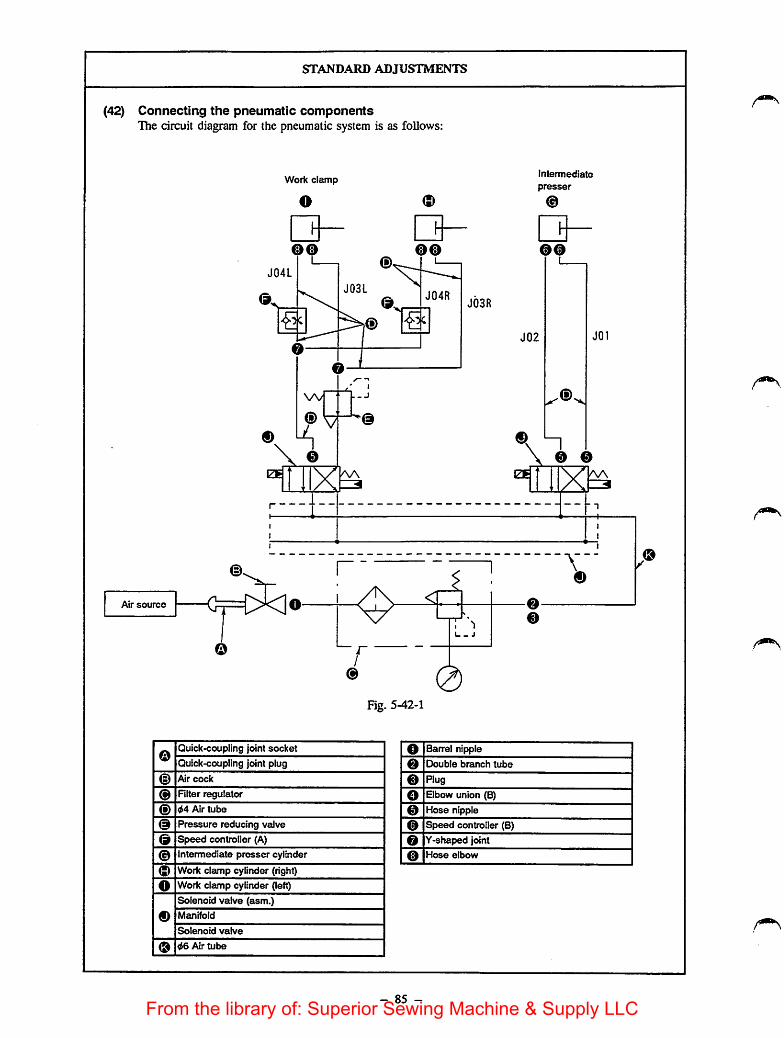
(42)
STANDARD ADJUSTMENTS
Connecting the pneumatic componentsThe circuit diagram for the pneumatic system is as follows:
iZfi
Work clamp
o
oo
W
ns ®
bk
V
_ j
AA
oo
J03R
intennediate
presser
00
J02 J01
iZE
\ n\ 0 0
0
Air source 00
<-H
1-
1- j
Fig. 5-42-1
0Quick-coupling joint socket 0 Barrel nipple
Quick-coupling joint plug 0 Double branch tube
© Air cock 0 Rug
0 RIter regulator 0 Elbow union (B)
© d4 Air tube 0 Hose nipple
© Pressure reducing vdve 0 Speed controller (B)
© Speed controller (A) 0 Y-shaped joint
Intermediate presser cylinder 0 Hose elbow
© Work clamp cylinder (right)
0 Work clamp cylinder (lett)
Solenoid valve (asm.)
0 Metn'rfold
Solenoid valve
0 d6 Air tube
- 85 -
0
From the library of: Superior Sewing Machine & Supply LLC

now TO ADJUST
Connect the pneumatic components referring to the circuitdiagram for the pneumatic system.If you use an air gun, you may connect the 06 mm air tubetojointo In thiscase, remove plug ®.
- 86 -
RESULTS OF IMPROPER
ADJUSTMENT
o The work clamp mechanism and/orintermediate presser mechanism maymalfunction. As a result, machinetrouble may occur or the correspondingcomponents may become damaged.
From the library of: Superior Sewing Machine & Supply LLC

DISASSEMBLY/ASSEMBLY PROCEDURES
(43) Removing the handwheel and the generator stator1) Loosen two setscrews O so that the handwheel is removed.2) Remove two outer setscrews O of the generatorstator, and loosen the two inner setscrews.3) Remove the generator stator.
Main shaft
Generator stator Setscrew No. 2
Handwheel
Marker dot No. 1
(44)
1)2)
3)4)
o
Setscrew No. 1
©Setscrews No. 2 Setscrews No. 1
115-43-1
Removing the wiper and the wiper solenoidRemove the connector.
Remove two setscrews O which retain the wipersolenoid installation plate. Then remove the wipersolenoid (asm.)Remove wiper solenoid locknut O.Loosen wiper solenoid bracket setscrew ©, andremove the wiper solenoid.
D
Wiper solenoid bracket
- 87 -
Connector
Fig. 5-44-1
Wiper solerK>id
©
From the library of: Superior Sewing Machine & Supply LLC

CAUTIONS IN DISASSEMBLY
1± 0. 5 i«n
M
Fig. 5-43-2
Fig. 5-44-2
- 88 -
CAUTIONS IN ASSEMBLY
o When installing the generator stater, besure that setscrews No. 2are alignedwith marker dot No. 1 on the bracket(Fig. 5-43-1).
o When fixing the handwheel, be sure thatsetscrews No. 1are located on the flatpart of the main shaft (observed from thecorrect rotational direction of rotation ofthe handwheel). At this time, adjust theclearance between the generator statorand the handwheel so that it is U0.5mm. (Fig. 5-43-2)
Be sure to fix wiper solenoid locknut 0by applying LOCK-TITE No. 242 paint.(Fig. 5-44-1)
IWhen tightening wiper solenoidinstalling plate setscrew O. be sure thatportion (D of the top end of the wiper isaligned with the center of the needle.(Fig. 5-44-2)
5Wiper solenoid bracket setscrew 0should befixed in the position asdescribed in the "STANDARDadjustments (9)." Press the wipersolenoid bracket in the direction ofarrow ©, and determine the position ofthe bracket so that the specifieddistances are obtained. (Fig. 5-44 1)
From the library of: Superior Sewing Machine & Supply LLC
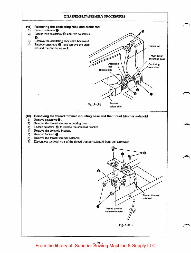
(45)
1)2)
3)4)
(46)
1)2)3)4)5)6)7)
DISASSEMBLY/ASSEMBLY PROCEDURES
Removing the oscillating rock and crank rodLoosen setscrew O •Loosen two setscrews e and two setsaews
eRemove the oscillating rock shaft backward.Remove setscrews 0 , and remove the crankrod and the oscillating rock.
Fig. 5-45-1
Osctllatngrock
Thrust collar
Shuttle
driver shaft
Crank rod
Thrust collar
mounting base
Oscillatingrock shaft
Removing the thread trimmer mounting base and the thread trimmer solenoidRemove setscrews O •Remove the thread trimmer mounting base.Loosen setscrew 0 to release the solenoid bracket.Remove the solenoid bracket.
Remove locknut 0Remove the thread trimmer solenoid.
Disconnect the lead wire of the thread trimmer solenoid from the connector.
- 89 -
Thread tnmmer
solenoid bracket
Fig. 5-46-1
Thread trimmer
solenoid
From the library of: Superior Sewing Machine & Supply LLC

CAUTIONS IN DISASSEMBLY
o Pay attention to the orientation of the cap of the crank rod.
Note that the thread trimmer solenoid lockouts are fixed usingthe LOCK-TITE paint.For removing the thread trimmer solenoid terminal from theconnector, see the solenoid connection diagram.
Thread trimmer
solenoid bracket
Thread trimmer
mounting base
/ Thread trimmer' , solenoid
Fig. 5-46-2
- 90 -
CAUTIONS IN ASSEMBLY
o Be sure that the oscillating rock is freefrom axial play,
o If the main shaft does not turn smoothly,correct the mounting position of thethrust collar and the thrust collar
mounting base.
o Fix the thread trimmer solenoid lockouts
by applying LOCK-TITE No. 242 afterdefatting them,
o To fix the thread trimmer solenoid
bracket, press the tension release shaftarm against the cam follower after fixingthe thread trimmer mounting base (Fig.5-47-1). Then, insert a screwdriverthrough © of the thread trimmermounting base, and tighten setscrew 0(Fig. 5-46-1). At this time, adjust theclearance between the trimmer solenoidbracket and the thread trimmer solenoid© to 0 mm. (Fig. 5-46-2)
o For the adjustment of the thread trimmermounting base, refer to "STANDARDADJUSTMENT (16)."
From the library of: Superior Sewing Machine & Supply LLC
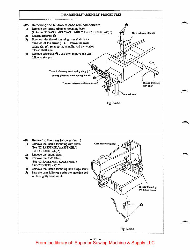
DISASSEMBLY/ASSEMBLY PROCEDURES
(47) Removing the tension release arm components1) Remove the thread trimmer mounting base.
(Refer to "DISASSEMBLY/ASSEMBLY PROCEDURES (46).")2) Loosen setscrewO •3) Draw out the thread trimming cam shaft in the
direction of the arrow (-»). Remove the resetspring (large), reset spring (small), and the tensionrelease shaft arm.
4) Remove setscrews 0, and then remove the camfollower stopper.
Cam follower stopper
(48)
1)
2)3)
4)5)
Thread trimming reset spring (large)
Thread trimming reset spring (small)
Tension release shaft arm (eism.)
Cam follower
Fig. 5-47-1
Removing the cam follower (asm.)Remove the thread trimming cam shaft.(See "DISASSEMBLY/ASSEMBLYPROCEDURES (47).")Remove the throat plate.Remove the X-Y table.
(See "DISASSEMBLY/ASSEMBLYPROCEDURES (55).")Remove the thread trimming link hinge screw.Pass the cam follower under the machine bed
while slightly bending it.
Cam follower (asm.)
Fig. 5-48-1
91 -
Thread trimmingcam shaft
Thread trimminglink hinge screw
On
On
OS
From the library of: Superior Sewing Machine & Supply LLC

CAUTIONS IN DISASSEMBLY
o Donot locKen rod adjusting screw nut O •
- 92 -
CAUTIONS IN ASSEMBLY
o Press the thread trimming cam shaft inthe direction of arrow © so that theend face of the stepped section of thethread trimming cam shaft comes inclose contact with the end face of thecam follower. Press the tension releaseshaft arm in the direction ofarrow © ,and tighten tension release shaft armsetscrew O •
J
Tension release ^shaft arm
Fig. 5-47-2
At this time, adjust thethrusting direction so that thetension release shaft arm(asm.) and the cam followerturn smoothly andindependently
Close contact
o When the cam follower (asm.) has beendisassembled, be sure to adjust thecenter-to-centerdistance of the pillowballs to 273.4±0.4 mm.
At this time, make sure that the jend faces of the upper and lowerpillow balls are parallel with eachother. J
End faces of thepillowballs(upper and lower)
Fig. 5-48-2
From the library of: Superior Sewing Machine & Supply LLC

DISASSEMBLY/ASSEMBLY PROCEDURES
(49) Disassembling the components of the intermediate presser lifting mechanism1) Carry out steps 1) through ^ of
"DISASSEMBLY/ASSEMBLYPROCEDURES (51) Disassembling thecomponents of the intermediate presserdriving mechanism."
2) Remove locknut O • Then remove washer0 , O ring O and the suspension linksupport shaft of the intermediate presser.
3) Loosen setscrews O and 0 >and draw outthe tension arm shaft in the direaion of
arrow ©.4) Remove the cylinder supporting screw of
the intermediate presser.5) Remove the air tube from speed controller
(B).6) Lift the intermediate presser cylinder (asm.)
in the direction of arrow ® until you havecompletely removed it.
[Caution]For the G type model of sewing machine,remove the intermediate presser liftingspring.
Setscrew
Cylinder supporting screwof the intermediate presser
Suspension linksupport shaft of theintermediate presser
Speed controller (B)
Tension
arm shaft
Tension arm
Intermediate pressercylinder knuckle
Intermediate pressercylinder (asm.)
Fig. 5-49-1
G type model ofsewing machine-
a
Intermediate presserlifting springmounting bracket
Fig. 5-49-2
- 93 -
Intermediate presserlifting spring
From the library of: Superior Sewing Machine & Supply LLC

CAUnONS IN DISASSEMBLY
o Be sure to remove the air tube from speed controller (B) whilepressing section ® in the direction of arrow ® .Use a mark to indicate the correct position for the reinstallationof the air tube which has been removed.
There are two different positions where the air tube canbe installed. One is on the push-out side and the other ison the pull-in side of the cylinder rod.
0O 1-1
ri
Air tubeAir tube
Fig. 5-49-3
- 94 -
CAUTIONS IN ASSEMBLY
o If the air tube is installed on the oppositeside, the intermediate presser maybecome lowered and may come incontact with the work clamp while themachine is engaged in feeding material.During sewing, the intermediate pressermay go up and come in contact with theneedle bar.
Adjust the speed controller usingadjusting saew 0, referring to the"STANDARD ADJUSTMENTS (41)Adjusting the pneumatic components."
o When the intermediate presser cylinderknuckle is removed, refer to the"STANDARD ADJUSTMENTS (22)Adjusting the intermediate presser liftingstroke."
o Tighten setsaew 0 whileslightlyshifting it in the direction of arrow 0with the tension arm shaft shifted in the
direction of arrow @. At this time,make sure that the tension arm turns
smoothly free from play,o Tighten setsaew O referring to the
"STANDARD ADJUSTMENTS (19)Release amount of the tension disks."
o When installing the intermediate pressersuspension link, be sure to apply greaseor lubrication oil to 0 ring 0 so that the0 ring does not become damaged.
From the library of: Superior Sewing Machine & Supply LLC

(50)
1)
2)3)4)5)6)
7)
DISASSEMBLY/ASSEMBLY PROCEDURES
Disassembling the components of the tension release mechanismRemove the thread trimmer mounting base referring to the "DISASSEMBLY/ASSEMBLY PROCEDURES(46)."Remove the thread trimming cam shaft referring to "DISASSEMBLY/ASSEMBLY PROCEDURES (49)."Remove the tension release reset spring.Ijoosen setscrew , and remove the tension release pin for controller No. 2.Remove setscrew O > remove the tension post bracket.Loosen setscrews 0 and O • Draw out the tension arm shaft, and remove tension arm (A) and the tensioncontroller connecting rod.Remove the tension release bushing in the direction of arrow © . Then remove tension release arm,connecting plate and tension arm (6).
Tension release bushingTension release arm
Tension release reset spring
Suspension connecting armof the intermediate presser
Tension arm (A)
Tension arm (B)
Tension controller
connecting rod
Tension release
connecting plate
Tension arm shaft
0 Tensionpost bracket
Tension
release pin
- 95 -
Tension controller No. 2
Fig. 5-50-1
From the library of: Superior Sewing Machine & Supply LLC
CAUTIONS IN DISASSEMBLY
o When removing the tension release reset spring, take care not todamage the spring hook. ,<<3
o When removing the tension release bushing, wedge a 08.5 to11.5 mm hammering bar from the side faa of the arm, and pushout the bushing in the direction of arrow ©
- 96 -
CAUTIONS IN ASSEMBLY
o Fit the tension release bushing so thatthe tension release arm moves smoothlywithout play. Make sure that the threadtrimming cam shaft turns smoothly andcan move in the axial direction,
o When fixing tension arm (A) and (B),refer to "DISASSEMBLY/ASSEMBLYPROCEDURES (49) Disassembling thecomponents of the intermediate presserlifting mechanism CAUTION INASSEMBLY."
From the library of: Superior Sewing Machine & Supply LLC

DISASSEMBLY/ASSEMBLY PROCEDURES
(51) Disassembling the components of the intermediate presser driving1) Set the air pressure to 0 kgfi'cm-.2) Remove setscrewO, and then remove the
intermediate presser.3) Loosen the nut of the intermediate presser
adjusting screw. Then remove theintermediate presser adjusting screw,intermediate presser guide bar and theintermediate presser spring.
4) Remove threesetscrews 0. Then removeintermediate presser link (A), theintermediate presser L-shaped link,intermediate presser positioning link andintermediate presser link (B).
5) Loosen setscrew 0 and then theintermediate presser guide bracket.
6) Pull up the intermediate presser bar untilyou have completely removed it.
[Caution]For the G type model of sewing machine,be sure to remove, in prior, intermediatepresser spring <§) and the intermediatepresser depressing piate.
Intermediate presseradjusting screw nut
Intermediate presserpositioning link
Intermediate presserlink (A)
Intermediate pr^serL-shape link
Intermediate presserlink (B)
Intermediate
Intermediate presserspring peg
Intermediate presserspring B
Intermediate presserdepressing plate
Intermediate presserlink roller
Hingescrew of ^intermediate presser link j
Hinge screw
0
Washer
mechanism
Intermediate presseradjusting screw
Intermediate presserguide bar
Intermediate presserspring
Intermediate presseroscillating shaft
Intermediate
presser guide bracket
Intermediate presserbar lower bushing
Intermediate
presser barpresser
Fig. 5-51-1
- 97 -
From the library of: Superior Sewing Machine & Supply LLC

CAUTIONS IN DISASSEMBLY
o Do not remove the intermediate presser bar lower bushing.If it has been removed, apply LOCK-TITE No. 242 around thebushing after removing any residual grease. Thenassemble it sothat the distance specified below is obtained.
Intermediate presserbar lower bushing
esj
cS
+1
Fig. 5-51-2
X-Arm
o Do not remove the intermediate presser oscillating shaft bushing.(It is fixed using LOCK-nTE.) If it has been removed, applyLOCK-TTrE No. 242 around the bushing after removing anyresidualgrease. Then assemble it so that the distancespecifiedbelow is obtained.
Direction of
the handwheel
Whetted
face \
Moscillating shaft bushing
V.
I Grease
Arm
Whetted
facer
JT -V-
1 Grease
1
-•Hj
—
//"/'h 3±0. Inm
iiiiiiiiiimi,
3±0. Imm ••
Fig. 5-51-3
- 98 -
CAUTIONS IN ASSEMBLY
o Assemble the intermediate presser bar,intermediate presser guide bracket andthe intermediate presser adjusting screw,referring to steps 1) and 2) of the"STANDARD ADJUSTMENTS (20)Intermediate presser."
o Apply grease to the abrasive part ofintermediate presser link (A), theintermediate presser L-shaped link,intermediate presser link (B), theintermediate presser positioning link andthe intermediate presser guide bracket.
o If the specified distance of 11±0.2 mmbetween bottom of the intermediate
presser bar loweringbushing and end ofthe arm is not obtained, the bottom ofthe intermediate presser may not be ableto be fixed properly.
o Be sure of the following when installingthe intermediate presser oscillating shaft.
1) Apply the grease to the hollowed sectionin the center of the inside of
intermediate presser oscillating shaftbushing.
2) Fix the thrust collar so that its whettedface faces toward the intermediate
presser osciUating shaft bushing.Additionally, the thrust collar must befixed using two setscrews so that theintermediate presser oscillating shaft isallowed to turn smoothly without play.
o Fix the intermediate presser rod bracketreferring to step 4) of the "STANDARDADJUSTMENTS (20) Intermediatepresser."
o Install the intermediate presser rodconnecting shaft referring to the"STANDARD ADJUSTMENTS (21)Vertical stroke of the intermediate
presser."o When fixing the intermediate presser
cam in its standard position, refer tosteps 2) and 3) of the "STANDARDADJUSTMENTS (20) Intermediatepresser."
From the library of: Superior Sewing Machine & Supply LLC

DISASSEMBLY/ASSEMBLY PROCEDURES
7) Remove oil wick O in ih® direction ofarrow O •
8) Remove nut0, and then remove washer0 , the intermediate presser rod connectingpin and the intermediate presser rodconnecting shaft.
9) Loosen setscrew O, and remove theintermediate presser rod arm.
10) Loosen the two setscrews retaining thethrust collar. Then remove the thrust collar.
Intermediate presseroscillating shaft bushing
Intermediate
presser rod
Intermediate
presser cam
Intermediate presser
Intermediate presserrod connecting pin
o
Thrust collar
Intermediate presserrod connecting shaft
Intermediate presserrod bracket
Fig. 5-51-4
(52) Disassembling the slide plate bearing and the work clamp slide plate1) Remove four setscrews O, and then remove the feeding frame bracket.2) Remove four setscrews 0, and then remove work clamp slide plate A, work clamp slide plate and slide
plate bearing.
Work clampslide plate
Slide platebearing
Work clampslide plate A
Feeding frame
Feed bracket
Fig. 5-52-1
- 99 -
From the library of: Superior Sewing Machine & Supply LLC

CAUTIONS IN DISASSEMBLY
11
11
Fig. 5-52-2
Slide plate bearing
Pre-load
adjusting screw(SS7120770SH)
Position the thinner (distance from V groove tosurface) one at the front.
Fig. 5-52-3
Work clampslide plate A
Work clampslide plate
Fig. 5-52-4
Spring pin(4 ea.) 100-800g
- 100 -
CAUTIONS IN ASSEMBLY
Pass oil wick O through theintermediate presser oscillating shaft.Then fold the end protruding from theshaft, and insert the folded end into theshaft as shown in Fig. 5-51-5.
Intermediate presseroscillating shaft
jmm
Oil wick
Fig. 5-51-5
o The slide plate bearing and the workclamp slide plate have been preliminarilyloaded. So, do not remove them unlessdoing so is quite necessary,
o If you removed them, position theslideplate bearing at thecenter of theworkclamp slideplate andlightly fix it usingthe pre-load adjusting screw.Move the work clamp slide plate up anddown to apply a uniform pre-load to itand securely tighten saew O.
{[Caution]The bearing produces a starting torque(sliding torque) of 100to 800 g when itstarts moving after H has come incontact with the spring pin whenmoving the work clamp slide plate upand down.
From the library of: Superior Sewing Machine & Supply LLC

DISASSEMBLY/ASSEMBLY PROCEDURES
(53) Removing the travel unit cover joint
Setscrew^^SM7030450SC
Travel unit cover stayB1154215000
Travel unit cover
fixing plate BB1156215000
Travel unit cover
B1153215000
Washer
WP0330501SB
Fig. 5-53-1
- 101 -
Travel unit cover
fixing plateB1155215000
Travel unit cover
mounting bracketB1157215000
Setscrew
SM4030401SC
From the library of: Superior Sewing Machine & Supply LLC

CAUTIONS IN DISASSEMBLY
[Caution]1. Attach the travel unit cover fixing plate
and travel unit cover fixing plate Bwith their sagging side faced towardthe travel unit cover.
2. Fix the travel unit mounting bracketswhile tightening a screw in the slot.
3. Attach the moving unit cover mountingbrackets with the face-to>face distance
between them set to 62.4±0.3 mm.
- 102 -
CAUTIONS IN ASSEMBLY
From the library of: Superior Sewing Machine & Supply LLC
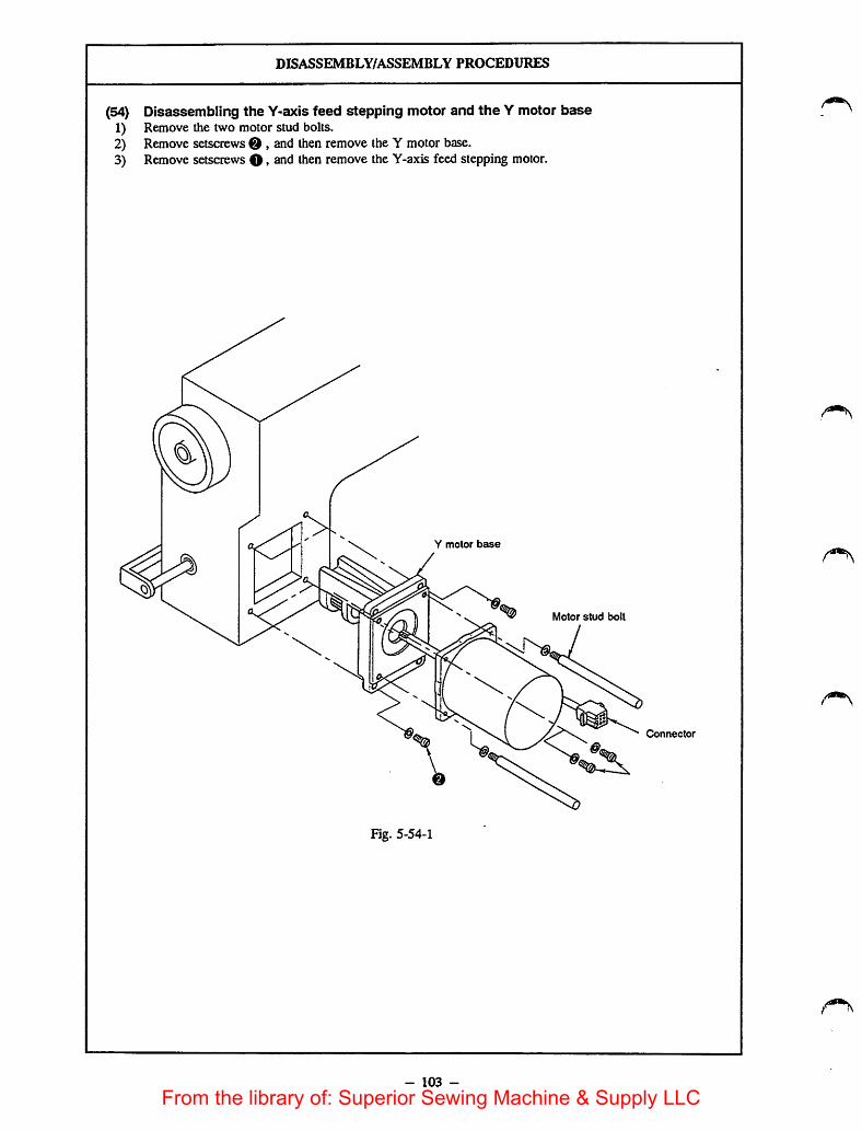
DISASSEMBLY/ASSEMBLY PROCEDURES
(54) Disassembling the Y-axis feed stepping motor and the Y motor base1) Remove the two motor stud bolts.2) Remove setscrews 0 , and then remove the Y motor base.3) Remove setscrewsO, and then remove the Y-axis feed stepping motor.
la
Y motor base
Motor stud bolt
Fig. 5-54-1
- 103 -
Connector
From the library of: Superior Sewing Machine & Supply LLC
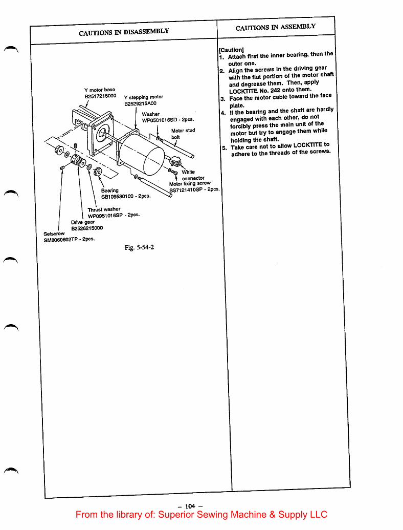
Y motor baseB2517215000 y stepping motor
B2529215A00
WasherWPOSCIOISSD - 2pcs.
Motor studbolt
BeanngSB109530100 - 2pcs
Thrust washerWP0951016SP -2pcs.
Drive gearB2526215000
Setscrew
SM8060602TP - 2pcs.
Fig. 5-54-2
White
connectorMotor fixing screwSS7121410SP - 2pcs
- 104 -
{Caution]1. Attach firstthe innerbearing, then the
outer one.
2. Align thescrews inthe driving gearwith thefiat portion of the motor shaftand degrease them. Then, applyLOCKTiTE No.242 onto them.
3. Face themotor cable toward theface
4. if thebearing and the shaft are hardlyengaged with each other, do notforcibly press the main unit of themotor but tryto engage them whileholding the shaft.Take care not to allow LOCKTiTE toadhere to the threads of the screws.
From the library of: Superior Sewing Machine & Supply LLC
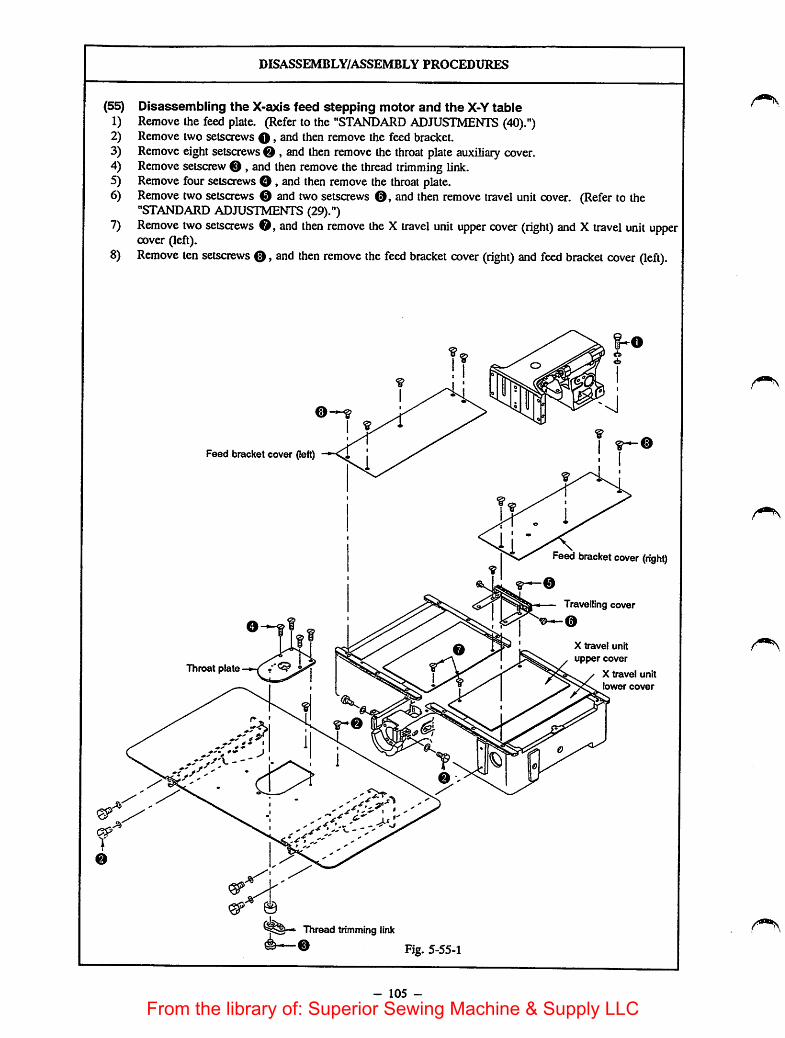
DISASSEMBLY/ASSEMBLY PROCEDURES
(55) Disassembling the X-axis feed stepping motor and the X-Y table1) Remove the feed plate. (Refer to the "STANDARD ADJUSTMENTS (40).")2) Remove two setscrews O, and then remove the feed bracket.3) Remove eightsetscrews 0 , and then remove the throat plate auxiliary cover.4) Remove setscrew 0 , and then remove the thread trimming link.5) Remove four setscrews O, and then remove the throat plate.6) Remove two setscrews 0 and two setscrews and then remove travel unit cover. (Refer to the
"STANDARD ADJUSTMENTS (29).")7) Remove two setsaews 0, and then remove the X travel unit upper cover (right) and Xtravel unit upper
cover (left).8) Remove ten setscrews 0, and then remove the feed bracket cover (right) and feed bracket cover (left)
Feed bracket cover (left)
Throat plate
^0
Thread trimming link
Fig. 5-55-1
- 105 -
Feed bracket cover (right)
Travelling cover
X travel unit
upper cover
X travel unit
lower cover
From the library of: Superior Sewing Machine & Supply LLC

CAUTIONS IN DISASSEMBLY
- 106 -
CAUTIONS IN ASSEMBLY
o When installing the feed bracket(left/right) cover and travelling cover,refer to the "STANDARD
ADJUSTMENTS (29)."o When installing the throat plate auxiliary
cover, refer to the "STANDARDADJUSTMENTS (25)."
o When installing the feed plate, refer tothe "STANDARD ADJUSTMENTS
(40)."o Carefully prevent oil from adhering to
the space located between the feed barand the X travel unit upper cover. If oilaccumulates there, an extra load will beapplied to the stepping motor, resultingin step-out of the motor.
From the library of: Superior Sewing Machine & Supply LLC

DISASSEMBLY/ASSEMBLY PROCEDURES
9) Remove the shuttle driver shaft. (Refer to the "DISASSEMBLY/ASSEMBLY PROCEDURES (57).")10) Remove four setscrews 0 , and then remove the X-axis feed stepping motor.11) Remove two setsaews 0 »and then remove the X guide shaft.12) Remove locknut ® and setsaew13) Remove ten setscrews (D and four setscrews ® , and then remove the X-Y table.
X-axis feed
stepping motor
Fig. 5-55-2
- 107 -
Connector (blue)
X guide shaft
From the library of: Superior Sewing Machine & Supply LLC

CAUnONS IN DISASSEMBLY
X-axis feed
stepping motor
/ Setscrew
Connector (blue)
Washer
@
2mni
Fig. 5-55-3
X slave gear
Setscrew m
Bearing
X drive shaft bracket
X drive shaft
Sprocket gsetscrew
Sprocket
X driven shaft
Fig. 5-55-4
123. 4±0. 2iwn
Fig. 5-55-5
Drive gear
Sprocket setscrew 0
/
\123.4±0.2(1*11
X driven shaft bracket (A)
- 108 -
CAUTIONS IN ASSEMBLY
o If you have removed thedriving gearfrom the X feed stepping motor,degrease thesetscrew and applyLOCKTITE No. 242 to it. Then, fix thedriving gearwhile adjusting theclearance provided between the end faceof the X feed stepping motor and thecoupling to 2 mm.
o If you have removed the X slave gear,lightly press it in direction A, andtighten setscrew in the Xslave gearafter applying LOCKTITE No. 242 ontothe setscrew. (Fig. 5-55-4)
o If you have removed the sprocket fromthe X driven shaft bracket (A), applyLOCKTITE No. 242 to setscrew ® andfix the sprocket to thebracket whileadjusting the clearance provided betweenthe sprocket and the end face of thebracket to 1 mm.
o Position and fix the X-Y table accordingto Fig. 5-55-5. (Standard throat platesetscrew hole dia.: Setscrew hole dia.11/64 pitch 40) After the Xguide shafthas been installed, move the guide platelaterally and longitudinally to make surethat the guide plate can be movedsmoothly.
o To adjust the belt tension, refer to the"STANDARD ADJUSTMENTS (31)."
o Adjust the clearance provided betweenthe X driving shaftbracket and themachined end face of the bed to 2 mm.
From the library of: Superior Sewing Machine & Supply LLC
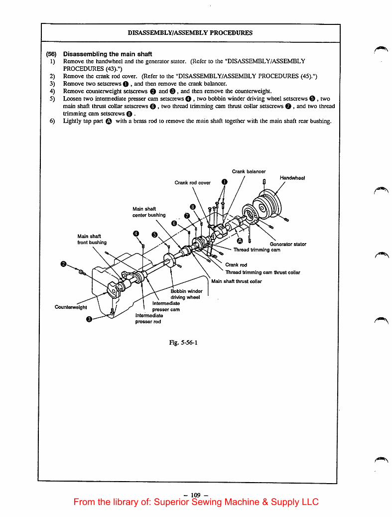
(56)
1)
2)3)4)5)
6)
DISASSEMBLY/ASSEMBLY PROCEDURES
Disassembling the main shaftRemove the handwheel and the generator stator. (Refer to the "DISASSEMBLY/ASSEMBLYPROCEDURES (43).")Remove the crank rod cover. (Refer to the "DISASSEMBLY/ASSEMBLY PROCEDURES (45).")Remove two setscrews O >and then remove the crank balancer.Remove counterweight setscrews 0 and0, and then remove the counterweight.Loosen two intermediate presser cam setscrews O »bvo bobbin winder driving wheel setscrews ©, twomain shaft thrust collar setscrews © , two thread trimming cam thrust collar setscrews 0, and two threadtrimming cam setscrews 0 .Lightly tap part © with a brass rod to remove the main shaft together with the main shaft rear bushing.
Main shaft
front bushing
Crank rod cover
Main shaft ®center bushing 0
Bobbin winder
driving wheelIntermediate
presser cam
Intermediate
presser rod
Cranl< balancer
Handwheel
Generator statorThread trimming cevn
Crank rod
Thread trimming cam thrust collar
Main shaft thrust collar
Counterweight
Fig. 5-56-1
- 109 -
From the library of: Superior Sewing Machine & Supply LLC

CAUTIONS IN DISASSEMBLY
o Be sure to use a brass rod or the like to tap part
Greasing hole
> II—on
["XShaft rear bushing
Fig. 5-56-2
Fig. 5-56-3
Main shaft
Counterweight
(Observed fromthe face plate)
Marker dot
Msun shaft Marker dot
Crank balancer Face plate
Fig. 5-56-4
- 110 -
CAUTIONS IN ASSEMBLY
1) When driving-in the rear bushing, besure to align the greasing hole in the armwith the greasing hole in the rearbushing.In addition, be sure that the end face ofthe rear bushing of the main shaft isflush with the end face of the arm at
face © . (Fig. 5-56-2)2) When fixing the counterweight, be sure
to insert setscrew O into screw hole© ,and fix the counterweight so that thetaper of the top end aligns with the taperhole in the main shaft. (Fig. 5-56-3)
3) Install the main shaft thrust collarreferring to the "STANDARDADJUSTMENTS (35)." (The oil grooveis located on the side of the intermediate
bushing.)4) When fixing the following parts, refer to
the corresponding "STANDARDADJUSTMENTS."
o Intermediate presser camSTANDARD ADJUSTMENTS (20)
o Bobbin winder driving wheelSTANDARD ADJUSTMENTS (24)
o Thrust collar of the thread trimming cam..... STANDARD ADJUSTMENTS (15)
o Thread trimming cam STANDARDADJUSTMENTS (15)
5) When fixing the crank rod cover, referto the "DISASSEMBLY/ASSEMBLYPROCEDURES (45)."
6) When fixing the crank balancer, makesure that the marker dot on the main
shaft aligns with the marker dot on thecrank balancer. (Fig. 5-56-4)
7) When installing the handwheel and thegeneratorstator, refer to the"DISASSEMBLY/ASSEMBLY
PROCEDURES (43)."
From the library of: Superior Sewing Machine & Supply LLC

DISASSEMBLY/ASSEMBLY PROCEDURES
(57) Removing the shuttle driver shaft1) Loosen driver selscrew O »2nd then remove theshuttle driver.2) Loosen thrust collar setscrew 0 , and the draw out the shuttle driver shaft ina backward direction,
[Caution]Never remove the dowel pin from the shuttle driver shaft gear.
Thrust collar
Dowel pin
Shuttle driver O
Thrust collar
Fig. 5-57-1
- Ill -
Shuttle
driver shaftShuttle driver
shaft front bushing
From the library of: Superior Sewing Machine & Supply LLC
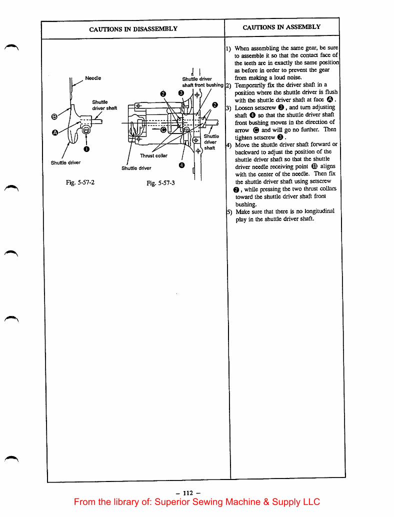
CAUTIONS IN DISASSEMBLY
Shuttle driver
Needle
Shuttle
driver shaft
Fig. 5-57-2
Thrust collar
Shuttle driver
Fig. 5-57-3
Shuttle driver
shaft front bushing
Shuttle
driver
shaft
- 112 -
CAUnONS IN ASSEMBLY
1) When assembling the same gear, be sureto assemble it so that the contact face ofthe teeth are in exactly the same positionas before in order to prevent the gearfrom making a loud noise.
2) Temporarily fix the driver shaft in aposition where theshuttle driver is flushwith the shuttle driver shaft at face ©.
3) Loosen setscrew ©, and turn adjustingshaft O so that the shuttle driver shaftfront bushing moves in the direction ofarrow ® and will go no further. Thentighten setsaew ©.
4) Move theshuttle driver shaft forward orbackward to adjust the position of theshuttle driver shaft so that the shuttle
driver needle receiving point © alignswith the center of the needle. Then fixthe shuttle driver shaft using setscrew
©, while pressing the two thrust collarstoward the shuttle driver shaft frontbushing.
5) Make sure that there is no longitudinalplay in the shuttle drivershaft.
From the library of: Superior Sewing Machine & Supply LLC
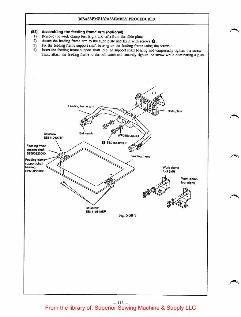
DISASSEMBLY/ASSEMBLY PROCEDURES
(58) Assembling the feeding frame arm (optional)1) Remove the work clampfeet (right and left) from the slide plate.2) Attach the feeding frame arm to the slide plate and fix it with screws O •3) Fix the feeding frame support shaft bearing on the feeding frame using the screw.4) Insert the feeding frame support shaft into thesupport shaft bearing and temporarily tighten the saew.
Then, attach the feeding frame to the ball catch and securely tighten the screw while eliminating a play.
Setscrew
SS8110422TP
Feeding framesupport shaftB2560220000
Feeding framesupport shaftbearingB2561220000
Feeding frame arm
Ball catch
Setscrew
SS1110840SP
WP0651056SD
O SS9151420TP
Feeding frame
Fig. 5-58-1
- 113 -
Slide plate
Work clampfoot (left)
Jir:
Work clampfoot (right)
From the library of: Superior Sewing Machine & Supply LLC

CAUTIONS IN DISASSEMBLY CAUTIONS IN ASSEMBLY
- 114 -
From the library of: Superior Sewing Machine & Supply LLC

DISASSEMBLY/ASSEMBLY PROCEDURES
(59) Assembling the optional tension release connecting arm (B23162150A0)1) Fit the tension release connecting arm in the tension arm over the tension arm shaft.2) Adjust the rising amount of the tension disk using the tension arm. (See page 49.)3) When the tension disk is raised (the tension release shaft arm rests on the tension release notch), adjust
the clearance provided between the tension release connecting arm and the intermediate presser connectingarm to 1 mm. Now, lightly press the pin mounted on the tension release connecting arm against theintermediate presser connecting arm, tighten the screw in the tension release connecting arm.
Tension arm
Tension arm shaft
Setscrew
Tension release
connecting arm
Fig. 5-59-1
- 115 -
Intermediate presserconnecting arm
From the library of: Superior Sewing Machine & Supply LLC
CAUTIONS IN DISASSEMBLY
- 116 -
CAUTIONS IN ASSEMBLY
o Besure toadjust the components withthe intemediate presser lifted to thehighest position of itsstroke
o After theassembling procedure, makesure that the tension diskrises as theintermediate presser goes up.
From the library of: Superior Sewing Machine & Supply LLC

Greasing parts• Supply grease when a grease-involving part has been disassembled oronce every other year.• Grease to be used:
Uthium-based grease No. 2
Manufacturer Name of grease
ESSO Listan 2, Beacon 2
SHELL Albania
NIPPON SEKIYU Multinock 2, Epinock 2KYODO SEKIYU Rezonix 2
IDEMTTSU KOSAN Koronex 2
Manufacturer Name of grease
ESSO Templex N3
Parts to be greasedIf no grease pump is available, it isadvisable to use a plastic oiler oran injector with the needle
Item
Parts to be
greased
Parts related
to greasing
Details
Y traveling shaft front bushing, insideY traveling shaft rear bushing, insideIntermediate presser oscillating shaft bushing, insideIntermediate presser oscillating shaft, abrasive facesIntermediate presser oscillating shaft thrust collar, abrasive facesIntermediate presser link hingescrew and each link, abrasive facesIntermediate presser lifting link support shaft, abrasive partsIntermediate presser lifting link, top endIntermediate presser lifting link, abrasive partsIntermediate presser lifting guide plate, abrasive partsShuttle race, needlecomponentsShuttle driver shaft rear/front bushing, needle componentsTension connecting rod, taper unit and abrasive partsTension release resetting spring, hookThread trimming cam, collarThread trimming cam roller, periphery and abrasive partsThread trimming link spring hookX-Y table retainer and tracking facesX guideshaft, abrasive partsX driving gearX-Y driving gearY traveling shaft, periphery and rack faceY driving gearBobbin winder adjusting components, abrasive partsTravelling cover (A) spring, hook and peripheryShuttle driver shaft thrust base, abrasive partsWork clamp leversupport, abrasive partsWork clamp lever, cylinder knuckle, abrasive partsWork clamplever, top endWork clamp slideplate, abrasive partsPresser plate, abrasive faces
Main shaft rear bushingBobbin winder shaft base, bearingInside of the linea bushing
Work clamp foot slider bracket
Bobbin winder adjusting components, abrasive partsIntermediate spring B, hookIntermediate presser foot plate, abrasive partsIntermediatepresser link rollerIntermediate presser lifterspring hook
- 117 -
removed.
Remarks
ESSO Listan 2
or the equivalent
ESSO TemplexN3
ESSO Listan 2
or the equivalent
ESSO TemplexN3
Only for the Gtype
From the library of: Superior Sewing Machine & Supply LLC

Parts to be fixed by LOCK-TITE paintThe machine is often started and stopped, so LOCK-UTE paint is used to securely fix the screws which arelikely to loosen easily.When an assembly which includes the above-mentioned screws has been disassembled, completely remove theresidual paint using a paint thinner, and re-assemble it using LOCK-TITE paint after removing any moisturefrom the mating faces. (Use LOCK-TITE No. 242 or No. 601)If it is hard to remove a saew which has been fixed using LOCK-TITE paint, heat it using a torch lamp to helpremove the screw.
The following components use LOCK-TITE paint.
Item Details Remarks
LOCK- Part No. Part Name Q'ty Use the LOCK-TITE No.
iTi'E paintapplyingparts
B2532220000* Y travelling shaft front bushing 1 242 after removing anyresidual grease.
B2532220000* Y travelling shaft rear bushing 1
B1605220000* Intermediate presser oscillating shaft bushing 2
B1403280000 Needle bar lower bushing 1
B1616220000 Intermediate presser bar lower bushing 1
SB712000100 Linear bushing 2
SS6150710SP Intennediate presser positioning pin 1
NM6Q40003SC Thread trimming solenoid lock nut 2
B2410220000 Thread trimming solenoid bracket pin 1 [Caution]NM6040003SC Wiper solenoid lock nut 2 For the four parts of
SS9151120CP Presser plate fixing screw 4whose part number aremarked with asterisks (*),use LOCK-TITE No. 242SL4031091SC Oil drain setscrew 4
SS8090410TP Setscrew for the face plate 1 after applying Rockwick
SS8110560SP Sealed screw for the face plate 2primer T grade.
B2540205B00 Setscrew of the driving gear 2
B1203215000* Main shaft center bushing 1
B2540205B00 Sprocket setscrew 4
SM8060602TP X, Y driving gear setsaew 4
SS8150822TP Bed hinge rod setscrew 2
SS7121610SP Motor setscrew 8
SS7151210SP Y-motor base setscrew 4
SS8150822TP X-guide shaft setscrew 2
PT03016G0SH Shuttle driver shaft taper pin 1 Use NUT LOCK after
removing any residualgrease
[Caution]Never allow LOCK-TITE paint to get Into the bearings, or else the bearings may not function properly.
- 118 -
From the library of: Superior Sewing Machine & Supply LLC
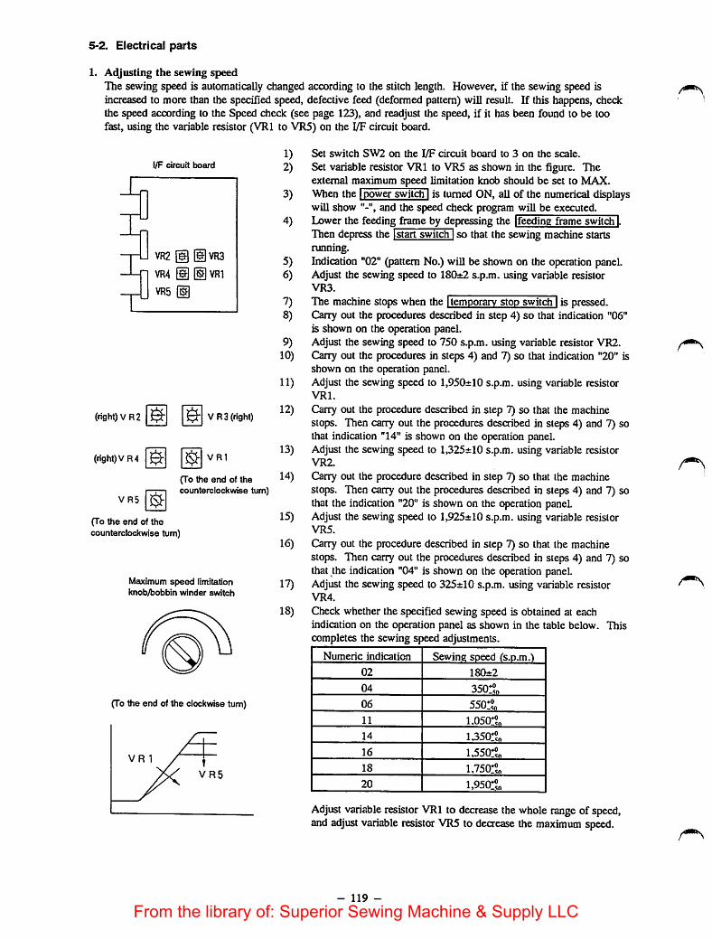
5-2, Electrical parts
1. Adjusting the sewing speedThe sewing speed is automatically changed according to the stitch length. However, if the sewing speed isincreased to more than the specified speed, defective feed (deformed pattern) will result. If this happens, checkthe speed according to the Speed check (see page 123), and readjust ^e speed, if it has been found to be toofast, using the variable resistor (VRl to VR5) on the I/F circuit board.
I/F circuit board
r
Li VR2
VR4
VR5
I
T
(1|VR3giVRI
(right)VR2 & $•
(right)VR4 &
VR3 (right)
VRl
VR5
(To the end of thecounterclockwise turn)
(To the end of thecounterclockwise turn)
Maximum speed limitationknob/bobbin winder switch
(To the end of the clockwise turn)
1) Set switch SW2 on the I/F circuit board to 3 on the scale.2) Set variable resistor VRl to VR5 as shown in the figure. The
external maximum speed limitation knob should be set to MAX.3) When the Ipower switch Iis turned ON, all of thenumerical displays
will show and the speed check program will be executed.4) Lower the feeding frame by depressing the [feeding frame switcFj.
Then depress the [start switchiso that thesewing machine startsrunning.
5) Indication "02" (pattern No.) wiU be shown on the operation panel.6) Adjust the sewing speed to 180±2 s.p.m. using variable resistor
VR3.
7) The machine stops when the [temporarv stop switdTI is pressed.8) Cany out the procedures described in step 4) so that indication "06"
is shown on the operation panel.9) Adjust the sewing speed to 750 s.p.m. using variable resistor VR2.
10) Carry out the procedures in steps 4) and 7) so that indication "20" isshown on the operation panel.
11) Adjust the sewing speed to 1,950±10 s.p.m. using variable resistorVRl.
12) Orry out the procedure described in step 7) so that the machinestops. Then carry out the procedures described in steps 4) and 7) sothat indication "14" is shown on the operation panel.
13) Adjust the sewing speed to 1,325±10 s.p.m. using variable resistorVR2.
14) Cilarry out the procedure described in step 7) so that the machinestops. Then carry out the procedures described in steps 4) and 7) sothat the indication "20" is shown on the operation panel.
15) Adjust the sewing speed to 1,925±10s.p.m. using variable resistorVR5.
16) Oirry out the procedure described in step 7) so that the machinestops. Thencarry out the procedures described in steps 4) and 7) sothat the indication "04" is shown on the operation panel.
17) Adjust the sewing speed to 325±10 s.p.m. using variable resistorVR4.
18) Check whether the specified sewing speed is obtained at eachindication on the operation panel as shown in the table below. Thiscompletes the sewing speed adjustments.
Numeric indication Sewing speed (s.p.m.)
02 180±2
04 350:?„06 550!?n11 1.050:^«
14 1350!5o16 l,550:®„
18 1,750:°„
20 i,95(r?„
Adjust variable resistorVRl to decrease the whole range of speed,and adjust variable resistor VR5 to decrease the maximum speed.
- 119 -
From the library of: Superior Sewing Machine & Supply LLC

2 Adiustin2 the PMDC circuit board current • r j ,u„• Two stepping motets are incorporated in the machine to actuate the fe^ m^anism, one
other for the Y-axis feed. Each motor is indepeodenUy actuate on the PMDC circuit board Since aU thecurrents are automaticaUy regubted, they do not need to be adjusted. Consequently, only the current chectan„procedure is described below.
(1) Checking the current connectors of J63, J64 and J65 have to be conneaed when only thediecking procedure is being carried out. The connector for J62 does nothave to be connected when checking the current.1) X-axis stepping motor (The X-axis stepping motor current flows
through fiise F2).(S) Be sure that the power switch has been turned OFF, and DIP switches
SWl and SW2 havebeenset to their ON side.(D Remove fuse F2. (Be careful not to remove circuit revision silk F-1 in
place of fuse F2. They look similar and are Ukely to cause confusion.)@Connect the ammeter (10 Adc class) to the fuse box offuse F2. (Take
care not to confuse "+" with "-".)®Be sure that DIP switches SWl and SW2 are set to their ON side, and
then turn ON the power switch.©If the ammeter indicates a current value within the range 2±0.2 A, the
electric current value of the X-axis stepping motor is normal.© Step DIP switch SW2 toits OFF side.@If the ammeter indicates a current value within the range 5±0.5 A, the
electric current value ofthe X-axis stepping motor is normal.©Set DIP switch SW2 once more to its ON side, and check for the
specified value 2±0.2 A on the ammeter.
normal operation, DIP switches SW1 and SW2 should be set totheir ON side.
This completes the checking of the electric current of the X-axis steppingmotor.
21 Y-axis steoDing motor (The Y-axis stepping motor current flows through fuse Fl.)®BeTre thaute power swi.ch has beenTurned OFF, and DIP swiiches SWl and SW2 have been set to their@Rraove fuse Fl. (Be caieful not to remove circuit revision silk F-1 in place of fuse Fl. Diey look similar
@O^ '̂toe Mmaer(lTAd '̂'S^^^ to the fuse box of fuse Fl. (Take care not to confuse "+" with®Be sure that DIP switches SWl and SW2 are set to their ON side, and then mm .©If the ammeter indicates acurrent value within the range 2a:0.2 A, the electnc current value of the Y-axis
stepping motor is normal.
@ff theTm^metCT acurrent value within the range 5±0.5 A, the electric current value of the Y-axis®̂ t"'™swUdh SwHnre more to its ON side, and check for the specified value 2±0.2 Aon the ammeter,
normal operation, DIP switches SWl and SW2 should be set to their ON side.
Dip SW
This completes the diecking of the electric of the Y-axis stepping motor.
- 120 -
From the library of: Superior Sewing Machine & Supply LLC

5-3. Rotary DIP switches for setting the test mode
DDDDOlD
Switch name
O Rotary DIP switch 1(SWl)
The rotary DIP switches, SWl and SW2 which are usedto set the function, are mounted on the I/F circuit board.[Caution]
When the power switch is turned ON, the machinewill perform reading out the setting of the switches.So, be sure to change the setting of the switchesafter the power switch has been turned OFF.
Function
O Rotary DIPswitch 2(SW2)
This switch is not used. Set this switch to "0".(It has been set to "0" at the time of delivery.)
• Set value "0" Normal operation. (At the time of delivery)
- 121 -
From the library of: Superior Sewing Machine & Supply LLC
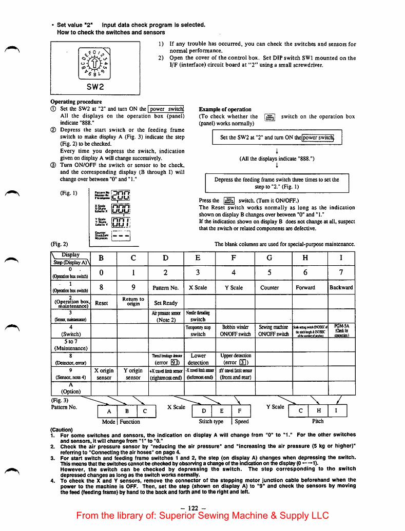
Set value "2" Input data check program is selected.How to check the switches and sensors
1) If any trouble has occurred, you can check the switches and sensors fornormal performance.
2) Open the cover of the control box. Set DIP switch SWl mounted on the1/F (interface) circuit board at "2" using a smaU screwdriver.
Operating procedure
(D
Set the SW2 at "2" and turn ON the | power switch[All the displays on the operation box (panel)indicate "888."
Depress the start switch or the feeding frameswitch to make display A (Fig. 3) indicate the step(Fig. 2) to be checked.Every time you depress the switch, indicationgiven on display A wiUchange successively.Turn ON/OFF the switch or sensor to be check,and the corresponding display (B through 1) willchange over between "0" and" 1."
(Fig. 1) !Dnn<
XSol*X-Skal*CcMttX
innrniiuLiui
inn ILuu i:
YSoltY'Sk9l»ethttit Y
CO(iRl««StUCUaM Imm ^Nbpiacts I
Example of operation(To check whether the
(panel) works normally)switch on the operation box
Set the SW2 at "2" and turn ON the|powerswitchj.
(All the displays indicate "888.")i
Depress the feeding frame switch three times to set thestep to "2." (Fig. 1)
Press the |j5h| switch. (Turn it ON/OFF.)The Reset switch works normally as long as the indicationshown on display B changes over between "0" and "1."If the indication shown on display B does not change at all, suspectthat the switch or related components are defective.
The blank columns are used for special-purpose maintenance.(Fig. 2)
\ DisplayStep (Display A)\
B c D E F G H I
0
(Opo^cotxKswiidi)0 1 2 3 4 5 6 7
1
(OpoatioaboK switch) 8 9 Pattern No. X Scale Y Scale Counter Forward Backward
2(Operation box,
maintenance)Reset
Retum toorigin Set Ready
3
(Soisor. mznoemiice)
Air piEssuie sensor(Note 2)
.Vndle thteado^
switch
4
(Switch)Tenipctaiy stop
switch
Bobbin winder
ON/OFF switch
Sewing machineON/OFF switch
SafeMatiniltKPiOKCaflixsaclilcetiiiltNOIECctttasiitc/sairiat
PGM-5A(Qetfigr(Oman.)
5lo7
(Maintenance)
8
(DeiectcH',error)
Thread ixeaiE2$e(Jeieaoc
(error [9])Lower
detection
detection
(error [3])9
(Sensor, note 4)
X originsensor
Y originsensor
•fXaavdhmii sensor
(rightmostend)
-Xaavdbnh sensor
(leftmost end)
travel limii sensa
(front and tear)
A
(Option)
X 7\(Fig. 3)Pattern No.
A B CX Scale
D E F
Mode Function Stitch type Speed
Y Scale
Pitch
(Caution)1. For some switches and sensors, the indication on display A will change from "0" to "1." For the other switches
and sensors, it will change from "1" to "0."2. Check the air pressure sensor by "reducing the air pressure" and "increasing the air pressure (5 kg or higher)"
referring to "Connecting the air hoses" on page 4.3. For start switch and feeding frame switches 1 and 2, the step (on display A) changes when depressing the switch.
This means that the switches cannot be checked by observing a change of the indication on the display (0 ->1).However, the switch can be checked by depressing the switch. The step corresponding to the switchdepressed changes as long as the switch works normally.
4. To check the X and Y sensors, remove the connector of the stepping motor junction cable beforehand when thepower to the machine is OFF. Then, set the step (shown on display A) to "9" and check the sensors by movingthe feed (feeding frame) by hand to the back and forth and to the right and left.
- 122 -
From the library of: Superior Sewing Machine & Supply LLC

Set value '3' Sewing speed check program is selected.This switch serves to check the specified sewing speed and the actual sewing speed.
(1) When the power switch is turned ON, all numerical displays will give At this time, turn the max.speed limit knob fully clockwise.
(2) When the start switch is depressed after the feeding frameswitch is depressed to lower the feeding frame,the displays will give "02", and the sewing machine will start to run at a low speed.
(3) When the temporary stop switch is pressed, the sewing machine will stop.(4) Each time steps (2) and (3) aboveare repeated, the sewingspeed is updated. By so doing, the sewing
machine speed for each stitch length can be checked.
Pattern No. indication Sewing speed
- 0 2 180±2
- 0 4 350:?o- 0 6 550!?o- 1 1 l,050!?o
- 1 4 l,350!?o- 1 6 1,550!»o- 1 8 l,750:^o- 2 0 l,950!?o
The sewing speed will be shown in the operation panel as follows:
(Example)
Pattern No.
X scale
Y scale
Counter
-
1 4
1 3 2
6
' These figures indicate that the sewingspeedof the machine is 1326 s.p.m.
- 123 -
From the library of: Superior Sewing Machine & Supply LLC

• Set value "4" The sensor check program isselected.The condition of the individual sensors can be checked.
Pattern No.
X scale
Y scale
Counter
- 0 1
-X xo ^X
- YO +Y
- --
The direction, + or - will be
-X
f -Y
determined by the position of the needle with regard to the feed hracket.
The display of the litnit sensor shows "0" when the Un.it is detected. When the sensor detects the points othermdtte7ofI origin'rrshows "1" when the sensor is in the . position, and shows "0" when the sensoris in the - position.
- 124 -
From the library of: Superior Sewing Machine & Supply LLC

• Set value "5" Origin check program is selected.The position of the origin can be checked.Besure to readjust the position of the origin using this program, whenever an origin-related part has beenreplaced.
(1) When the power switch is turned ON, thesame indications as the "sensor check program" will be shownin the display on the operation panel.
(2) Depress the start switch after the feeding frame switch is depressed to lower the feeding frame.(3) The feed bracket moves to the origin, and then stops.(4) The feed bracketpermits to be moved using the jog keys.(5) Each time thestart switch is depressed, the origin will be searched repeatedly.(6) The condition of the sensors wiU beshown on the operation panel as the sensor check program.
Generally, the machine origin will beset at the point where the numerical display changes from 1 to 0.Accordingly, the displays on the operation panel at the origin will be as follows;
Pattern No. - 0 1
1
1 0 1
- 0 1
- - -
X scale
Y scale
Counter
Set value "6" Continuous sewing Is selected.
(1)(2)(3)
(4)(5)
As the normal sewing, the program is read from the floppy disk, when the set ready switch is pressed.Depress the feeding frame switch so that the feeding frame comes down.Step on the start switch, and the machine will start sewing. Upon completion ofa sewing cycle, themachine will stop at the sewing start point.After the machine pauses about five seconds, the machine will automatically resume continuous sewing.After completion ofsewing, stop the machine by pressing the temporary stop switch. Turn OFF thepower switch after the origin has been retrieved.
- 125 -
From the library of: Superior Sewing Machine & Supply LLC

• Selecting the set value 'B' for specifying the output check program
(1) When the power switch is turned ON, the display A will give "0" and displays B through I will give "1."
Pattern No.
X Scale
Y Scale
Counter
A B C
D E F
G H I
-- -
(2) When the feeding frame switch or the start switch is depressed, the step on the display A will be updated.(3) When any of the numericalkeys 0 through 7 is pressed in each step, the corresponding output will be
turned ON.
At the same time, the specified display will give "0."Note that, however, the output is turned ON only when the numerical key is held depressed.
key
^
B C D E F G H I
0 1 2 3 4 5 6 7
0Feeding frame,
rightFeeding frame,
left
Intermediate
ptesserInversion
Thread wiper(solenoid valve)
Thread clampDouble-steppedstroke feeding
frame
Optionalsolerwid valve
1Thread trimmer
(solenoid)Thread wiper
(solenoid)External output External output External output External output External output
Tension
controller No. 3
2Optional
photo-coupler 1Optional
photo-coupler 2Optional
photo-coupler3Optional
photo-coupler4Optional
photo-coupler 5Optional
photo-coupler 6Optional
photo-coupler 7Optional
photo-coupler 8
[Caution]Do not press the numerical keys continuously when checking the output of the thread trimming solenoid orthread wiper solenoid.Doing so may break the corresponding solenoid or transistor.
- 126 -
From the library of: Superior Sewing Machine & Supply LLC

6. FUNCTION
6-1. How to set the memory switches
6-1-1. Key switches to be used
•JUKIAMS
Command key for changing function No.Command key for changing set item 1Command key for changing set item 2Command key for changing set item 3Update key (+1)Update key (-1)Memory switch setting mode end keyMemory switch setting mode cancel keyMemory switch setting mode keyY Scale Y Scats
@
©
®
@
6-1-2. Operating the memory switches[Start level of the memory switches]
There are two different start levels for the memory switches as described below.Level 1: The function that allows selection of performances or change of set values which are supposed to be
comparatively frequently changed is actuated. (Example: Operation mode of the intermediate presser,bobbin thread counter mode, etc.)
Level 2: The function that allows setting of special performances at the time of modification or more detailedoperation modes is actuated. The level 2 actuates while including the function that actuates on thelevel 1.
[STEP 1] Starting procedure
[How to start the level 1] [How to start the level 2]
Set the rotary DIP switch (SWl) on the I/F circuit boardto "0."
Set the rotary DIP switdi (SWl) onthe I/F circuit board to "3."
Turn ON the power switch while keeping the
[Indication]
READY
I Input
Indication of function No.
Set item 1
Set Kem 2
Set item 3
key on the operation panel held depressed.
The displays give the indications asshown below.
[Caution]The function No. indication changes depending onthe type of start level, i.e., level 1 or level 2. Fordetails, refer to "6-1-4. Memory switch setting leveltable" and the "Contents" (on pages 129 and 130).
- 127 -
From the library of: Superior Sewing Machine & Supply LLC

6-1-3. Entering the memory switch setting modeTurn ON the power switch while keeping the key on theoperation panel held depressed. In this case, the followingindications will appear on the displays.
•QaE3&y•E3DSI -.y I
Indication of function No.-
Set item 1 -
Set item 2 •
Set item 3
RgAOY g„er I jI iNumftcn
llnpul t I
Panetn No. o /U U '
Saaiiyp. is>».a
The function No. of the memory switch isshown on the patternNo. display.Each function has as many as three different set items. The setvalues are shown on the XScale, YScale and Counter displays.Ifthe function does not have all ofthe three set items," willappear on the display corresponding to the lacking set item.
Example:001: Indicates the selection of the jog function.002: Indicates the second origin selling.
- 128 -
From the library of: Superior Sewing Machine & Supply LLC

6-1-4. Memory switch setting level table and contents
Function
No.Function Item
Start
level 1
Start
level 2
PageNo.
0 Memory 1. Initialization of RAM O 134
2. Initialization of EEP-ROM O 134
1 Jog function 1. Jog mode O 135
2 X coordinate of receding position 1. Coordinate o 136
3 Y coordinate of receding position 1. Coordinate o 136
5 Retainer compensation 1. Mode O 137
6 Returning route to the sewing start point 1. At the end of sewing o 138
2. Travel limit error 0 138
7 Returning route from a midpoint in sewing 1. Mode o 139
8 Mechanical origin compensation 1. Amount of X compensation o 140
2. Amount of Y compensation o 140
13 Enlargement/reduction 1. Mode O 141
21 Cycle sewing 1. Performance of feeding frame(cycle sewing)
O 142
22 Thread trimming command 1. Switch o 143
30 Bobbin thread counter 1. Counting o 144
31 Floppy disk data reading operation 1. Selection of function o 145
2. Regular reading o 145
33 Automatic pattern reading from floppy disk 1. Mode o 146
35 Idling operation 1. Speed changing o 147
36 Thread trimming at the time of temporarystop
1. Thread trimming actiono 147
40 Selection of sewing speed 1. Acceleration at the sewing start 0 148
2. Selection of feed pitch/sewingspeed
o148
41 Feed control 1. Feeding position o 148
42 Thread trimmer control 1. Control o 149
43 Feeding frame control 1. Operation sequence o 150
2. Feeding frame holding state at theend of sewing
o 150
3. Regular holding o 150
44 Intermediate presser control 1. Control o 151
2. Operation timing o 151
45 Wiper 1. Sweeping position o 152
2. Sweeping position o 152
46 Thread clamp performance 1. Switch 0 153
Z Thread clamp mechanism o 153
47 Selectionof thread breakage detectingfunaion control
1. Switch o 154
Z Setting the number of stitchesrequired to stop the machine (at thestart)
o 154
3. Setting the number of stitchesrequired to stop the machine(during normal operation)
o 154
- 129 -
From the library of: Superior Sewing Machine & Supply LLC

Function
No.Function Item
Start
level 1
Start
level 2
PageNo.
48 Selection of air pressure detectins function 1. Switch O 155
49 Selection of needle-up position deteaingfunction
1. SwitdiO 155
51 Inverting mechanism control 1. Switch O 156
53 Tension controller No. 3 control 1. Switch O 156
55 Buzzer control 1. Switch O 157
56 Selection of floppy disk data readingsequence
1. Retrieving sequenceO 157
81 Wiper fmagnetl sweeping action ON/OFF timing o 158
82 Wiper (air) sweeping action ON/OFF timing o 159
84 Intermediate presser action timing ON/OFF timing o 160
- 130 -
From the library of: Superior Sewing Machine & Supply LLC
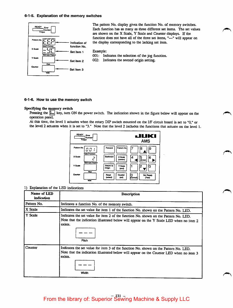
6-1-5. Explanation of the memory switches
f—1INumber |
• input I I
XScate
YScalo
Indication of
function No.
Set item 1
Set item 2
Set item 3
The pattern No. display gives the function No. of memory switches.Each function has as many as three different set items. The set valuesare shown on the X Scale, Y Scale and Counter displays. If thefunction does not have all of the three set items, "—" will appear onthe display corresponding to the lacking set item.
Example:001: Indicates the selection of the jog function.002: Indicates the second origin setting.
6-1-6. How to use the memory switch
Specifying the memory switchPressing the key, turn ON thepower switch. The indication shown in the figure below wiU appear on theoperation panel.At this time, the level 1 actuates when the rotary DIP switch mounted on the I/F circuit board is set to "0," orthe level 2 actuates when it is set to "3." Note that the level 2 includes the functions that aauate on the level 1,
Error f—]INumberl
ll/iput 1 I
Uodol
ReCum to
Orion
PdRerrt No
YScalo
kJUKIAMS
•••SI QBQ
•anSet Ready
crest)
1) Explanation of the LED indications
Name of LED
indication
Pattern No.
X Scale
Y Scale
Counter
Description
Indicatesa function No. of the memory switch.
Indicates the set value for item 1 of the function No. shown on the Pattem No. LED.
Indicates the set value for item 2 of the function No. shown on the Pattem No. LED.Note that the indication illustrated below will appearon the Y Scale T.F.n when no item 2exists.
Pitch
Indicates the set value for item 3 of the function No. shown on the Pattem No. LED.Note that the indication illustrated below will appearon the Counter LED when no item 3exists.
Width
- 131 -From the library of: Superior Sewing Machine & Supply LLC

2) Function of the setting switches and how to operate them
Name of switch | Function. Used to change the function No. of the
memory switch shown on the Pattern No.LED.
Panern No.
X Scale
(fevSew)
Y Scale
(end)
Counter j(set)
switch and ? or 8T A
key.
Used to change the set value for item 1ofthe function No. shown on the X ScaleLED.
Select a function No. using theswitch and ^^ ^A
XScaloReview)
• Used to change the set value for item 2 ofthe function No. shown on the Y ScaleLED.
Select a function No. using theswitch and 2 _ or 8 ^ key.2 or 8
T A
YSeal*[eniD
Used to change the set value for item 3ofthe function No. shown on theCounterLED.
Select a function No. using theswitch and ^^ ^a.
- 132 -
Press the
Press the
i
Operation
• To change the function No. from 41 to 46
switch.
key five times.
• To change the set value from 2 to 0
switch.XScaM
(teview)
key twice.
• To change the set value from 3 to 1
switch.YSolo
(end)
key twice.
• To change the set value from 2 to 6
Press the switch.(jcO
Press the Is key four times.
From the library of: Superior Sewing Machine & Supply LLC

Name of switch
Set Ready(Test)
Function
Used to terminate the memory switchsetting procedure.
READY Error [ 11 J Number
1Input 1 1
Pattern No. rrn
Mode 1 function
X Scale - ur
Stitchtype 1Speed
Y Scale
Pitch
Counter
1Width
Operation
Press the Set Ready switch.
Indication shown in the figure given on theleft will appear on the operation panel.
• To make the set values effeaive
switch.Press thel
To make the set values ineffective and
return the machine to the state before
starting up the memory switch settingmode
Press the key.
Press the| switch twice
The memory switch setting mode willterminate and the machine will return to the
state where the machine enters immediatelyafter the power to the machine has beennormally turned ON.
[Note]A number shown on the LED can be continuously increased/decreased by keeping the orpressed. '—'
key held
[Caution to be takenwhen using the memory switches]Function No. that is not described in the Engineer's Manual may be shown on thedisplay. However, neverchange the setting of the set items available under the function No. Changing the setting might impair the normaloperation of the sewing machine. If you change any of those settings unintentionally, be sure to performinitialization following the procedure described below. After the initialization, all the memory switches will beinitialized to their initial state.
[How to initialize the memory switches]It is possible to initialize the memory switches using item 2 of memory switch function No. 0 (initialization ofmemory switches).Determine the setvalue of item 2 in accordance with the specifications of the type of your sewing machine andterminate the memory switch setting procedure. Then, input data.This returns all the memory switches to their initial state.
[Caution]Ifthe memory switches have been separately specified, write downthe respective set values on a sheet ofpaper or the like. Then, start the aforementioned operation.
- 133 -
From the library of: Superior Sewing Machine & Supply LLC
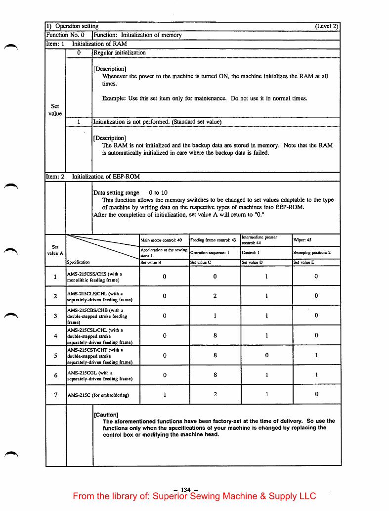
1) Operation setting (Level 2)
Function No. 0 Function: Initialization of memory
Item: 1 Initialization of RAM
0 Regular initialization
[Description]Whenever the power to the machine is turned ON, the machine initializes the RAM at alltimes.
Set
value
Example: Use this set item only for maintenance. Do not use it in normal times.
1 Initialization is not performed. (Standard set value)......................................... —
[Description]The RAM is not initialized and the backup data are stored in memory. Note that the RAMis automatically initialized in care where the backup data is failed.
Item: 2 Initialization of EEP-ROM
Data setting range 0 to 10This function allows the memory switches to be changed to set values adaptable to the typeof machine by writing data on the respeaive types of machines into EEP-ROM.
After the completion of initialization, set value A will return to "0."
Set
value A
Main motor control: 40 Feeding frame control: 43Intermediate pressercontrol: 44
Wiper: 45
Acceleration at the sewingstart: 1
Operation sequetice: 1 Control: 1 Sweeping position:2
Specification Set value B Set value C Set value D Set value E
1AMS-215CSS/CHS (with amonoiithic feeding frame)
0 0 1 0
2AMS-215CLS/CHL (with aseparately-driven feeding frame)
0 2 1 0
3AMS-215CBS/CHB (with adouble-stepped stroke feedingframe)
0 1 1 0
4
AMS-215CSUCHL(with adouble-stepped strokeseparatelv-driven feeding frame)
0 8 1 0
5AMS-215CST/CHT (with adouble-stepped strokeseparately-driven feeding frame)
0 8 0 1
6AMS-215CGL (with aseparately-driven feeding frame)
0 8 1 1
7 AMS-215C (for embroidering) 1 2 1 0
[Caution]The aforementioned functions have been factory-set at the time of delivery. So use thefunctions only when the specifications of your machine is changed by replacing thecontrol box or modifying the machine head.
- 134 -
From the library of: Superior Sewing Machine & Supply LLC

1) Operation setting (Level 1)
Function No. 1 Function: Jog function
Item: 1 Jog mode
Set
value
0 Jog function is ineffective.
[Description]The jog keys (
Pattern travel
and 2^ ) are inoperative.
[Description]A sewing pattern can be moved to a specified position by operating the jog keys (
~ ).1^1 and
Pattern data read from a floppy disk is moved to a new location by adding a distance bywhich the pattern data is to be moved using the jog function.The second origin contained in the pattern data is rendered ineffective. This setting can bereset by turning ON then OFF the Set Realty
(Test)switch.
The setting can also be canceled when readinganother sewing pattern.
To change the setting, create a new "point" using jog keys(andThis erases the previously set point.
).
After you have input data, the newly specified "point" is stored in memory together with theoriginal patterndue to the "backup function" even turning OFF the power to the machine.
[Example] Move the sewingpattern using jog keys.
Jump
-5^'
Origin
Jump
The 2nd origin setting (standard set value)[Description]
The position specified using the jog keys ( ^ ^ andorigin.
) is set as the 2nd
A 2nd origin is specified for the convenience's sake during jumpfrom the origin of thesewing pattern read from a floppy disk to thesewing start point without actually moving thesewing pattern.In this case, the 2nd origin contained in the pattern data will be ineffective. This setting canbe reset by turning ON then OFF the
[Example]
X'
Origin
The 2nd origin setting
Set Ready(Test)
X
Origin
switch.
2nd origin newlyspecified usingthe jog keys.
[Description]A 2nd origin is specified in accordance with the set values of X and Y written in EEP-ROM.
[Caution]When this code is used, the 2nd origin specified in a sewing pattern is renderedineffective.In this data setting procedure, jog keys ( and
A 2nd origin is set in accordance with the set values of function Nos. 2 and 3.) are not operative.
- 135 -
From the library of: Superior Sewing Machine & Supply LLC

|l) Operation settingIFunction No. 2 |Coordinate of the location of 2nd origin[item: 1 Setting an Xcoordinate of the location of 2ndl^gin
Setting the location of 2nd origin (X coordinate) (Standard set value 0)+32767
(Level 2) I
set value ofjogmode (No. 1)of thespecified tor this item determines the location of 2nd ongm. The Xcoordinate is shownwith five figures number on the XY Scale LED.
Unit: Set value x 0.1 mm
Example]
Set
value
Sewing start
/Sewingend point̂Sewing end point-
Sewing start
1) Operation settingFunction No. 3 [Coordinate of the location of 2nd originItem: 1 Setting aYcoordinate of the location of 2nd origin
'setting the lo^of2nd origin (Y coordinate) (Standard set value 0)
Set
value
+32767
Origin (2nd origin -50mm) Origin
After the location of the 2nd origin is specified «nn v ml(When the location of the 2nd origin is set to apoint X=-500, Y-U)
figure number on the XY Scale LED.
Unit: Set value x 0.1 mm
- 136 -
From the library of: Superior Sewing Machine & Supply LLC

1) Operation setting (Level 1)Function No. 5
Item: 1
Set
value
Retainer compensation function is inoperative.[Description]
Retainercomf)ensating performance is prohibited.Retainer compensation:The built-in X-Y table retainer of thesewing machine may shiftout of position after aprolonged use.In this case, theshape of a sewing pattern willbe deformed or the origin retrieval failure willbe caused
Inorder to prevent the aforementioned troubles, the position of the retainer can beforciblycorrected after pressing the switch for the first timeafter turning ON the power tothe machine. This performance is called "retainer compensation performance."
[Note]Besure to make the machine perform the retainer compensation unless a specialperformance is required. Retainer
Stopper
Retainer
Retainer compensation is effective (standard set value)[Description]
Retainer compensation performance is rendered effectiveThe machine performs theretainer compensation only when theonceafter turning ON the powerto the machine. However, when thepressed for the second time and beyond, the machine will not perform the retainercompensation.(D Automatic retainer compensation performance
When the ispressed for the first time after turning ON the power to themachine. Thefeeding frame comes down and the feed moves limit-to-limit within itstravel range. (After that, the feed stops at the sewing start point or the 2nd origin and thefeeding frame rests in the highest position ofits stroke.)Even when you press the for the 2nd time and beyond, the retainer compensationis not performed.To manually perform retainer compensationTurn OFF the power to the machine. Gradually move feed O back and forth and rightand left until the respective travel limits are reached. (Once a day)
[Caution]if a special-purpose feeding frame is installed onyour machine, theneedle may breakthrough the automatic retainercompensation performance. So, be sure to correct theretainer manually. To do this, carefully check the location of the needle.
switch is pressedswitch is
ON
- 137 -
From the library of: Superior Sewing Machine & Supply LLC

1) Operation setting (Level 1)
Funaion No. 6 Returning route to the sewing start point
Item: 1 When the sewing machine completes sewing' >
0 The machine does not retrieve the mechanical origin. (Standard set value)
[Description]The mechanical origin retrieval performance is not carried out.
1 The machine retrieves the mechanical origin.
[Description]After the completion of sewing (thread trimming), it is possible to move the machine to thesewing start point (or the 2nd origin) by way of the mechanical origin.
Set<Example>
value
Origin ^.1 Onginretneva! performance
y (When the set value Is 1)/ s ^ Normal performance
^ (When the setvalue Is0)
Sewfngend point Sewing
start point
Item: 2 When a travel limit error occurs.
0 The machine does not retrieve the mechanical origin.
Set
value
[Description]The mechanical origin retrieval performance is not carried out.
1 The machine retrieves the medianical origin. (Standard set value)
[Description]When a travel limit error has occurred during sewing, the machine retrieves the origin, thenmoves to the sewing start point (or 2nd origin).
- 138 -
From the library of: Superior Sewing Machine & Supply LLC

1) Operation setting (Level 2)
Function No. 7 Returning route from a midpoint in sewing
Item: 1 Mode setting
Set
value
0
2~
Origin is retrieved along the data on the returning route stored in the system ROM.set value)
(Standard
[Description]For a standard sewing pattern, the machine returns to the sewing start point taking theshortest route. For an inversion pattern, the machine returns to the start point while avoidingthe crank of inverting intermediate presser.
The machine performs mechanical origin retrieval.
[Description]The machine retrieves the origin from some midpoint in sewing (temporary stop at amidpoint in sewing pattern, thread breakage detection, etc.) and returns to the sewing startpoint.
<Example>
Origin retrieval performance(whienset value is 1)
Nonmal performance(when set value is 0)
Sewing start point
Special type of origin retrieving route
[Description]In casewhere a special-purpose feeding frame or the like is used withyou sewing machine,the machine is allowed to return to the origin taking a special route by inputting dataon theroute in the system ROM.
[Caution]Ifyou want to use a special route, it is necessary to change the system ROM.
- 139 -
From the library of: Superior Sewing Machine & Supply LLC

1) Operation setting(Level 2)
Function No. 8 [Mechanical origin c^pensationItem: 1
Set
value
X axis mechanical orign compensationXaxis mechanical origin compensation value setting (Standard set value 0)-99-
^°^Tx°^s mechanical origin can be correaed artificiaUy by the amount specified for thisitem.
mei^ feeding frame and sewing pattern that have been prepared using the other sewingmachine, this function corrects a mechanical error.
Item: 2 Y axis mechanical origin compensationYaxis medianical origin compensation value setting (Standard set value )-99-
[D^puo^^ mechanical origin can be corrected arUficially by the amount specified for thisitem.
- 140 -
From the library of: Superior Sewing Machine & Supply LLC
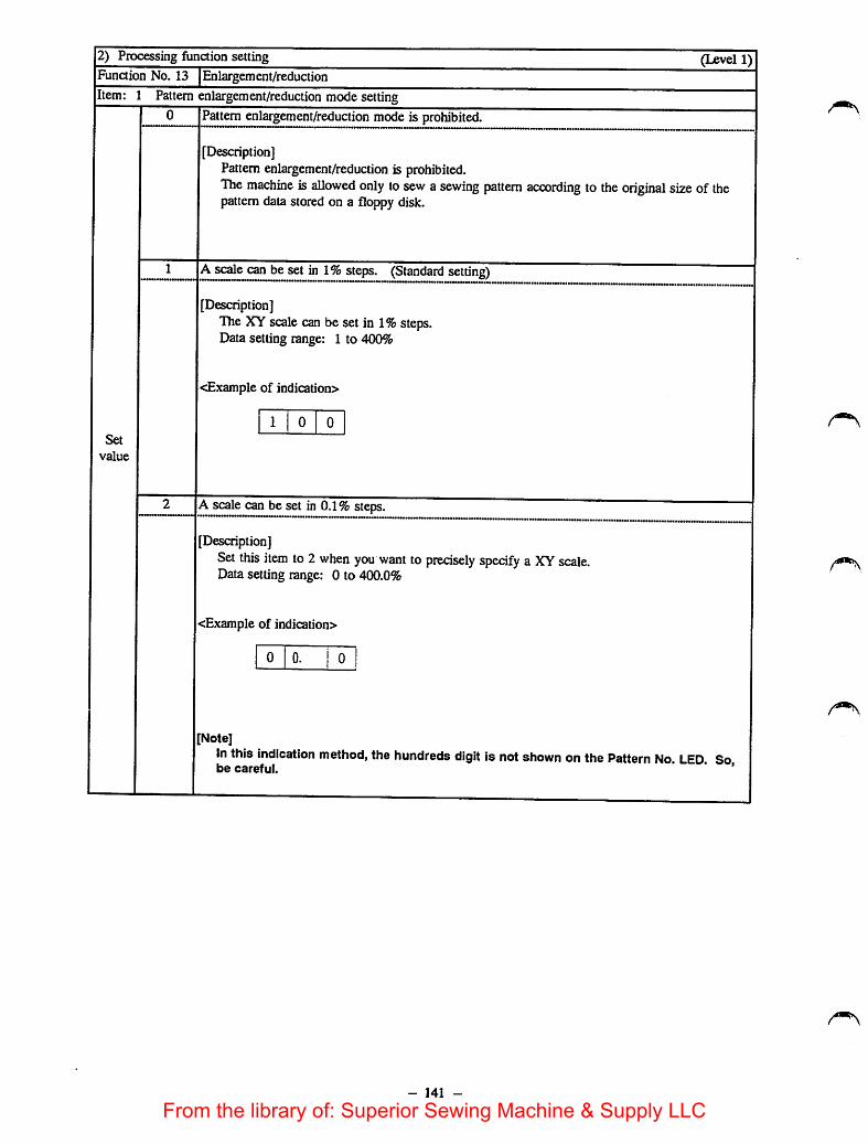
2) Processing function setting (Level 1)Function No. 13 Enlargement/reductionItem: 1 Pattern enlargement/reduction mode setting
Set
value
Pattern enlargement/reduction mode is prohibited.
[Description]Pattern enlargement/reduction is prohibited.The machine is allowed only to sew a sewing pattern according to the original size of thepattern data stored on a floppy disk.
A scale can be set in 1%steps. (Standard setting)
[Description]The XY scale can be set in 1%steps.Data setting range: 1 to 400%
<Example of indication>
1 0
A scale can be set in 0.1% steps.
[Description]Set this item to 2 when you want to precisely specify a XY scale.Data setting range: 0 to 400.0%
<Example of indication>
0 0. ! 0
Note]In this indication method, the hundreds digit is not shown on the Pattern No. LED Sobe carefui. '
- 141 -
From the library of: Superior Sewing Machine & Supply LLC

3) Command control (Level 1)Function No. 21 Cycle stitchingItem: 1 Performance of the feeding frame
Set
value
0 The feeding frame is held in the lowest position to secure the workpiece on the machine,feeding frame cannot be operated using the pedal switch.)
(The
[Description]If a temporary stop command has been entered in the sewing pattern used, the feeding framewill not go up even when the sewing machine stops.
The feeding frame is held in the lowest position to secure the workpiece on the machine. (Thefeeding frame can be released from the aforementioned position by operating the pedal switch.)(Standard set value)
[Description]If a temporary stop command has been entered in the sewing pattern used, the feeding framecan be raised by operating the feeding frame pedal switch after the sewing machine stops.
* Cycle sewing means to sew several sewing processes (cycles)continuously. The feeding frame goes up to allow you tochange the workpiece if you have entered a temporary stopcommand at the desired point in a pattern so as to divide thepattern at that point.
The feeding frame can be released from the lowest position. (The feeding frame can be loweredto secure the workpiece on the machine by operating the pedal switch.)[Description]
If a temporary stop command has been entered in the sewingpattern used, the machine temporarily stops at that point andraises the feeding frame. Then, the feeding frame can be loweredby operating the pedal switch. c
[Caution] When the cycle sewing function is ON,take the below-stated precautions.
When the Forward or Backward key is pressed, the feed halts at the preset temporary stopposition where the feeding frame can be raised or lowered using the feeding frame switch. Ifyou want to continueto move the feed forward or backward, lower the feeding frame andre-start the operation.
The Return to Origin switch is used to return the machineto the start point of the first cyclein a sewing pattern. If you want to return the machine to the start of the current cycle, usethe Backward key.
The Counter on the display counts the bobbin thread at the completion of a sewing pattern.If three cycles are input in a pattern, the Counter countsafter the completion of the threecycles.
The Set Ready switch is rendered ineffective while a sewing pattern (between cycles) even ifthe feeding frame goes up. Press the Set Ready switch after pressing the Return to Originswitch or after the c:ompletion of the pattern.
- 142 -
From the library of: Superior Sewing Machine & Supply LLC
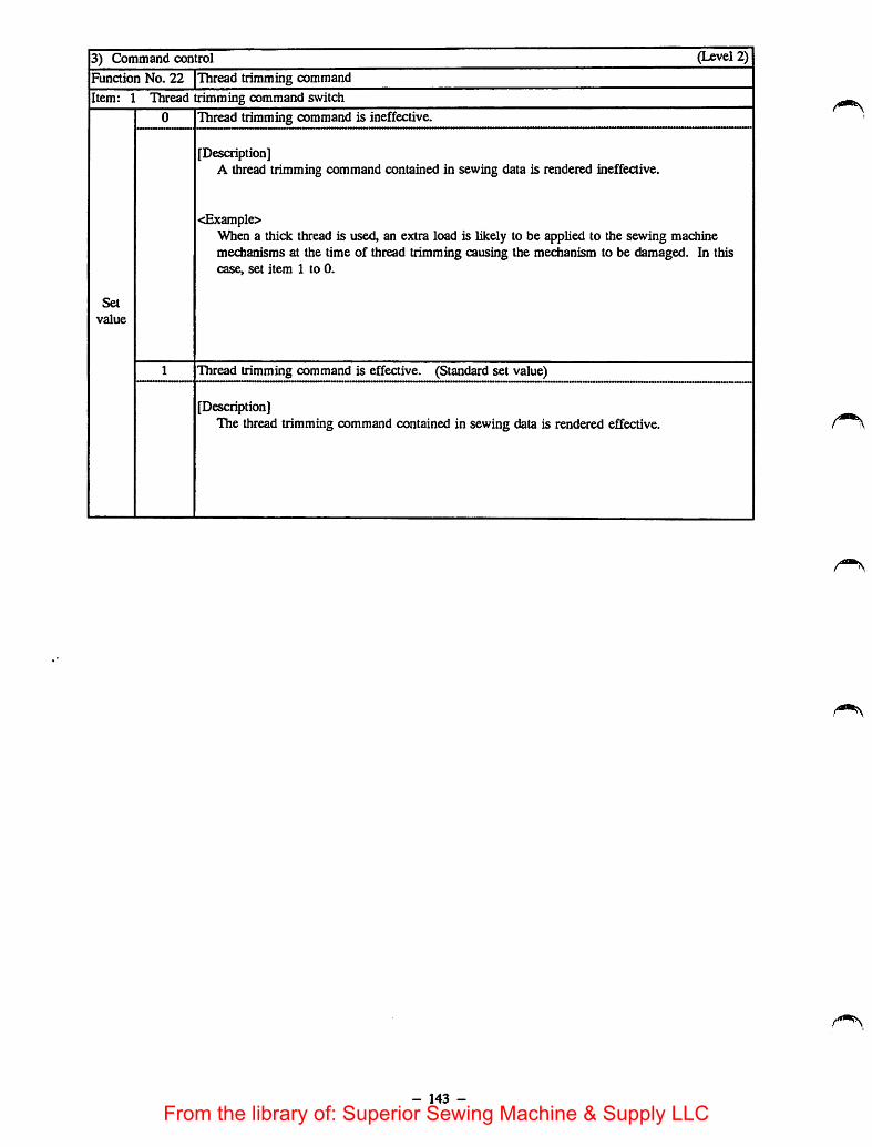
3) Command control (Level 2)
Function No. 22 Thread trimming command
Item: 1 Thread trimming command switch
Set
value
Thread trimming command is ineffective.
[Description]A thread trimming command contained in sewing data is rendered ineffective.
<Example>When a thick thread is used, an extra load is likely to be applied to the sewing machinemedianisms at the time of thread trimming causing the mechanism to be damaged. In thiscase, set item 1 to 0.
Thread trimming command is effective. (Standard set value)
[Description]The thread trimming command contained in sewing data is rendered effective.
- 143 -
From the library of: Superior Sewing Machine & Supply LLC

14') Operation system controlFunction No. 30 |Bobbin thread counter
lltem: 1 Operation mode setting"O lUP counter (loop) (Standard set value)
(Level 1)]
Set
value
" • »s«i.Press the
down counter (loop)
• switch, tmd the value on the bobbin thtead counter will be reset to 999.Press the
T IT IP counter (The counter stopswhen the predetermined value is reached.)
mSin thread counter operates as an adding counter,specify the number of tta^ ^^^000^^ LE
CotAner
(set) switch and
specify the number of tirn^ u,e Counter LED^^h on and off tonumeric key, then press the witm
machine is ready for sewing. ^mnietes one cycle stitching, the value shown on theThen, every time the sewing jg reached. 'When the specified value isCounter LED will mcrease untd ® ^ ^ow, the sewing machine isreached, the value shown on the LED wiu iiasn onincapable of continuing sewing any further.
["down counter (The counter stops when u^reach^
mt^ulr subtracts from the specified value until 000 is reache^en 000 is reached,Coufttf 1 . .
the sewing machine sloi»- . .. .uread counting using theSpecify the number of times of bobbi specified value every time the sewingbobbin thread counter wiU cached, the Counter LED wiU flash onmachine completes acyde shtchmg. e^mSuing sewing any further,an off. Now, the sewing machine ^ pe reset to enable the sewingP-U.C ® :^fEtith»rS^Sdcountriesamadiine tostart sewing. E Mcino the I Counter j SWitCh.
- 144 -
CourtCf I . j *u(Mrti j switch, and the
Counter
(set)
From the library of: Superior Sewing Machine & Supply LLC
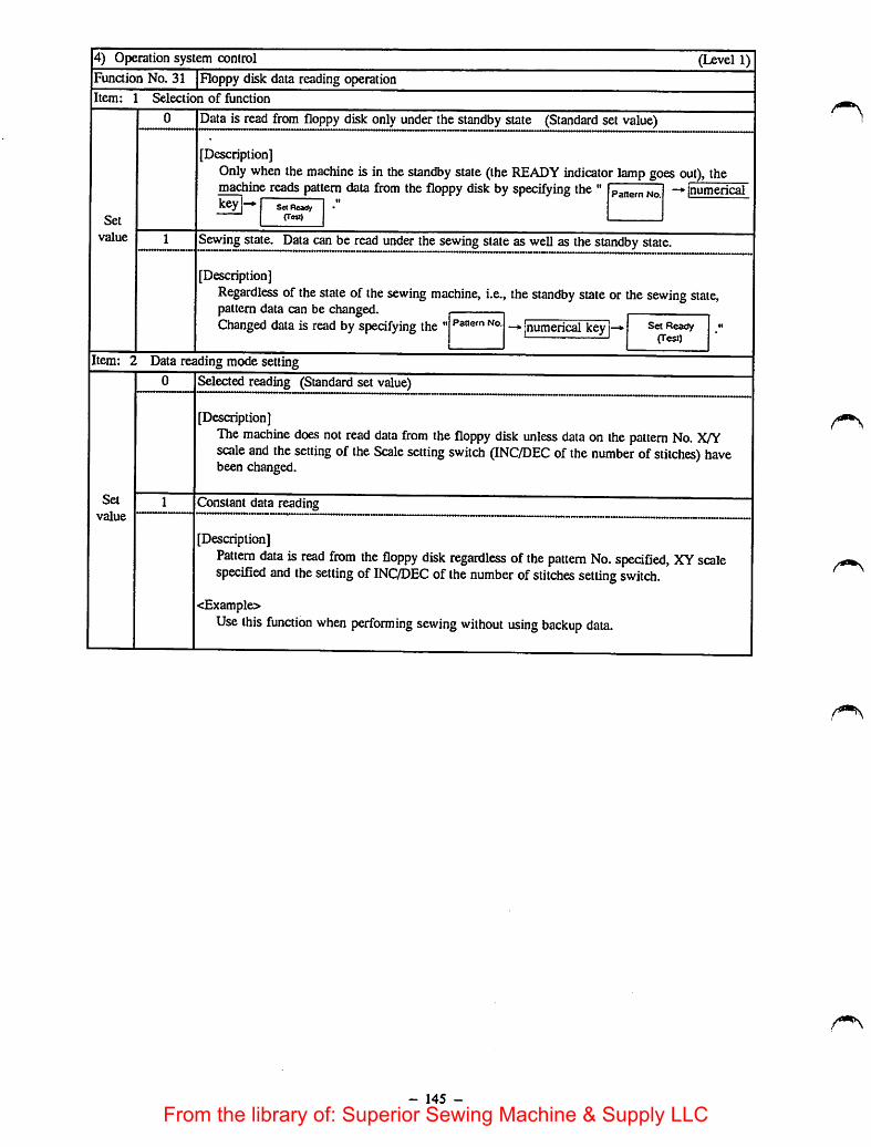
4) Operation system control (Level 1)Function No. 31 Floppy disk data reading operationItem: 1 Selection of function
Set
value
0 Data is read from floppy disk only under the standby state (Standard set value)
[Description]Only when the machine is in the standby state (the READY indicator lamp goes out), themachine reads pattern data from the floppy disk byspecifying the " -*• |numericalRey |—*• se« Reatty
fTeaJ
1 Sewing state. Data can be read under thesewing stateas well as thestandby state.
[Description]Regardless of the state of the sewing machine, i.e., the standby state or the sewing state,pattern data can be changedChanged data is read by specifying the"•jnumerical key i—• Set Ready «•
' (Test)
Item: 2 Data reading mode setting
Set
value
0 Selected reading (Standard set value)
[Description]The machine does not read data from the floppy disk unless data on the pattern No. X/Yscale and the setting of the Scale setting switch (INC/DEC ofthe number ofstitches) havebeen changed.
1 Constant data reading
[Description]Pattern data is read from the floppy disk regardless ofthe pattern No. specified, XY scalespecified and the setting of INC/DEC of the number ofstitches setting switch.
<Example>Use this function when performing sewing without using backup data.
- 145 -
From the library of: Superior Sewing Machine & Supply LLC

4) Operation system control (Level 2)
Function No. 33 Automatic pattern reading from floppy disk
Item: 1 Mode setting
Set
value
0 Continuous reading is ineffective (Standard set value)
[Description]The continuous pattern reading function is inoperative.
Continuous reading is effective
[Description]After the completion of sewing, the subsequent pattern data is read from the floppy disk.If the pattern numbers are not consecutive, the machine will enter the standby state to aUowa pattern No. to be selected.
[Operating procedure]After specifying 1 for the set value, press thedisplay shows Ih] to enable continuous pattern reading. If [Hj is not shown on the Error
Backward
switch. Then, the error number
Number display, the machine will perform the normal operation.
<Example>Pattern Nos. will be as ITl -*
- 146 -
• ^ 13 - E.
Temporary stop state (READY indicator lampgoes out.)When "5" is specified, the machine proceeds tothe subsequent operation.
From the library of: Superior Sewing Machine & Supply LLC

4) Operation system control (Level 2)Function No. 35 Idling operation
Item: 1 Speed changing
0 Constant speed (Standard set value)
[Description]The machine runs idle at a constant speed at all times.
Set
value 1 2-step speed
[Description]While the machine performs jumping of sewing data, the jump speed can be increased byturning ON the Start switch.
4) Operationsystem control (Level 1)
Function No. 36 Selection of thread trimming after turning ON the temporary stop switch.
Item: 1 Thread trimming setting
0 Thread trimmer automatically actuates.
[Description]When the temporary stop switch is pressed, the sewing machine temporarily stops and thethread trimmer actuates.
1 Thread trimmer is manually actuated. (Needle threading switch is used.) (Standard set value)
Set
value
[Description]When the temporary stop switch is pressed, the sewing machine stops and error No. "5" willflash on and off on the operation panel.In this state, the thread trimmer is actuated by turning ON then OFF the needle threadingswitch.
2 Thread trimmer is manually actuated. (Temporary stop switch is used.)
[Description]When the temporary stop switch is pressed, the sewing machine stops and error No. "5" willflash on and off on the operation panelIn this state, the thread trimmer is actuated by pressing the temporary stop switch again. Thethread trimmer can also be actuated by operating the needle threading switch.
- 147 -
From the library of: Superior Sewing Machine & Supply LLC

|5) Mechanism controlFunaion No. 40 [Selection of the sewing speedIItem: 1 Acceleration at the start of sewing
(Level 1)
Set
value
0-4 '&l'L^ion of me acceleration at Ihe sewmg Stan (depends on me setting of item i ol lunaion No.1) ... —
Description]The start-up speed ofthe sewing speed is speafied.uTb. .0 one of .he six different stages. (Set value 1ts excluded.)Set value 0: The standard start-up speed. (Standard set value)set value 1: &t ^ eight different stages.)
Set value 2: High speed modeSetvalue 3: Medium speed mode 1Set value 4: Medium speed mode 2
Item: 2 •<;p.winp soeed adapting to the material thicknessSewing speed adapting to the material thickne^
Set
value
Set
value
0-3
0-9
Description] . ^mited to ensure a
"^gth .0 - fed'alter the needle h. conte of, thematerial.
Set value 0: 2,000 s.p.m. Ught-weight material
Set value 1: 1,600 s.p.m.
Set value 2: 1,300 s.p.m.
Set value 3: 1,000 s.p.m. Extra heavy-weight matenal
Selection
Description]The feed start timing can bethickness.
advanced by 0to 9pulses so as to adapt to the matenal
9: Advances *—
(Thick materials)-•0: Retards (Standard value: 0)
(Thin materials)
'''"when the max. sewing yorop«me*'y^u^racW^^^^Jith the max.C:L~dratT^^T-% t-e feed'' stad timing at the standard set value.
- 148 -
From the library of: Superior Sewing Machine & Supply LLC

5) Mechanism control (Level 1)
Funaion No. 42 Thread trimmer prohibition
Item: 1 Designation of thread trimmer prohibition
Set
value
0 Thread trimmer is ineffective.
[Description]Thread trimming is prohibited under any condition.
<Example>When a thick thread is used, an extra load is likely to be applied to the sewing machinemechanisms at the time of thread trimming causing the mechanism to be damaged.
Thread trimmer is effective. (Standard set value 0)
[Description]All the functions related to the thread trimmer are rendered effective.
The thread trimmer operates under the operation mode in accordance with the set values ofFunction Nos. 22 and 36.
- 149 -
From the library of: Superior Sewing Machine & Supply LLC

5) Medianisra control (Level 1)
Function No. 43 Feeding frame controlItem: 1 Operation sequence setting
Set
value
0-31 Selection of the feeding frame (Standard set value depends on the setting of item 2 of functionNo. 1.)
[Description]Refer to "(6-1-7) Feeding frame control."
Item: 2 Selection of the state of feeding frame at the sewing end
Set
value
0 The machine returns to the sewing start, then the feeding frame goes up. (Standard set value)
[Description]After the completion of sewing, the sewing machine travels to the sewing start point, lifts thefeeding frame and waits for the start of next sewing.
1 The machine returns to the sewing start and stops with the feeding frame lowered.
[Description]After the completion of sewing, the sewing machine travels to the sewing start point andwaits for the start of next sewing with the feeding frame lowered.At this time, the feeding frame can be raised with the Feeding frame switch.
[Caution]The machine cannot be re-started unless the feeding frame is raised and lowered once.
2 The feeding frame goes up to its intermediate stop position while the sewing machine returns tothe sewing start.
[Description]The feeding frame goes up to the first step of the double-stepped stroke during jump fromthe sewing end. Then the feeding frame is held raised until the machine reaches the sewingstart
3 The feeding frame goes up to its intermediate stop position while the sewingmachine returns tothe sewing start
[Description)The feeding frame goes, up to the second step of the double-stepped stroke during jump fromthe sewingend. Then the feeding frame is held raised until the machine reaches the sewingstart.
Item: 3 Selection of the constant-lowering of the feeding frame
Set
value
0 Normal control (Standard set value)
[Description]The feeding frame can be raised/lowered by operating the Feeding frameswitch.The feeding frame operates under the operation mode in accordance with the set valuesofitems 1 and 2.
1 Constant-loweringof the feeding frame during sewing
[Description]As long as the READY indicator lamp is ON, the feeding frame is always held lowered.
<Example>Thisoperation mode is used when sewing a labelor the like that is placed inside the feedingframe.
- 150 -
From the library of: Superior Sewing Machine & Supply LLC
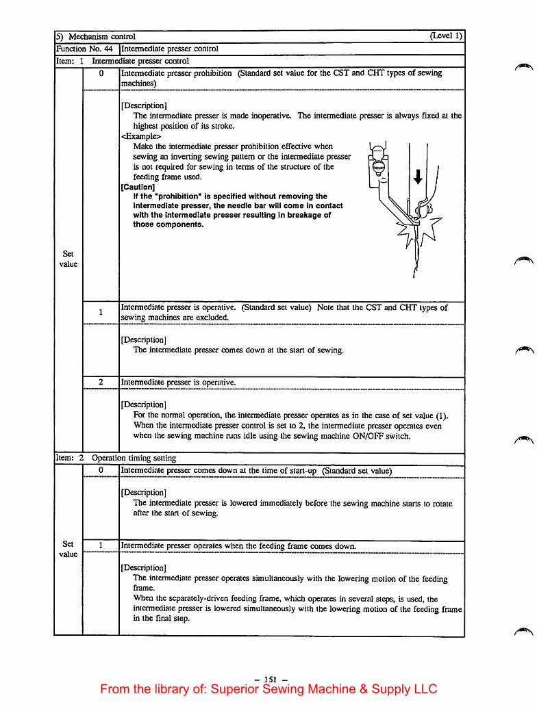
5) Mechanism control (Level 1)
Function No. 44 Intermediate presser control
Item: 1 Intermediate presser control
Set
value
0 Intermediate presser prohibition (Standard set value for the CST and CHT types of sewingmachines)
[Description]The intermediate presser is made inoperative. The intermediate presser is always fixed at thehighest position of its stroke.
<Example>Make the intermediate presser prohibition effective whensewing an inverting sewing pattern or the intermediate presseris not required for sewing in terms of the structure of thefeeding frame used.
[Caution]If the "prohibition" is specified without removing theintermediate presser, the needle bar will come in contactwith the intermediate presser resulting in breakage ofthose components.
Intermediate presser is operative. (Standard set value) Note that the CST and CHT types ofsewing machines are excluded.
[Description]The intermediate presser comes down at the start of sewing.
Intermediate presser is operative.
[Description]For the normal operation, the intermediate presser operates as in the caseof set value (1).When the intermediate pressercontrol is set to 2, the intermediate presseroperates evenwhen the sewing machine runs idle using the sewing machine ON/OFF switch.
Item: 2 Operation timing setting
Set
value
0 Intermediate presser comes down at the time of start-up (Standard set value)
[Description]The intermediate presser is lowered immediately before the sewing machine starts to rotateafter the start of sewing.
Intermediate presser operates when the feeding frame comes down.
[Description]The intermediate presser operates simultaneously with the lowering motion of the feedingframe.
When the separately-driven feeding frame, which operates in several steps, is used, theintermediate presser is lowered simultaneously with the lowering motion of the feeding framein the final step.
- 151 -
From the library of: Superior Sewing Machine & Supply LLC
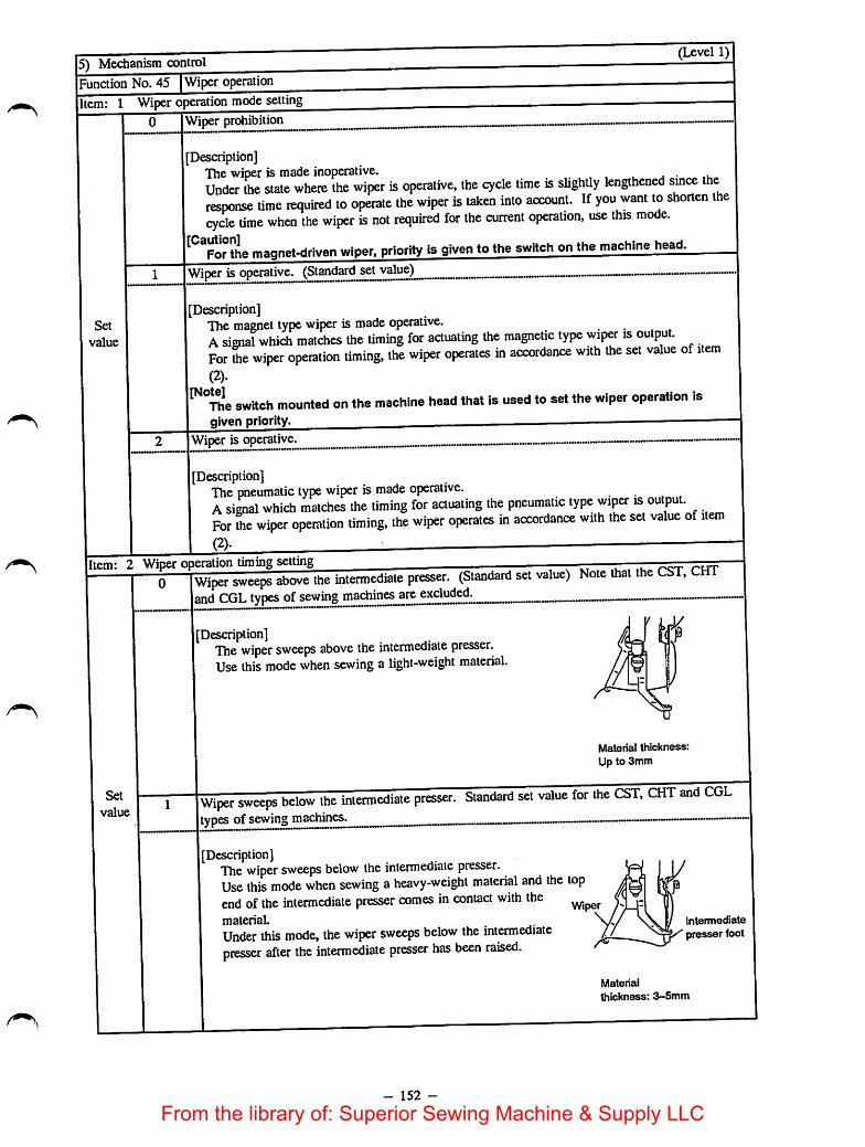
15) Mechanism control(Level 1)
IFunction No. 45 Wiper operationlltem: 1 Wiper operation mode setting
Set
value
Wiper prohibition
Description]The wiperis madeinoperative. , j • ,uUnder the state where the wiper is operative, the cycle time is slightly lengthened smce theresponse time required to operate the wiper is taken into account. If you want to shorten thecycle time when the wiper is not required for the current operation, use this mode.
'̂ °For the magnet-driven wiper, priority is given to the switch on the machine head.Wiper isoperative. (Standard set value)
Description]The magnet type wiper is made operative. . • . ,Asignal which matches the timing for actuating the magnetic type wiper is output.For the wiper operation timing, the wiper operates in accordance with the set value of item(2).
switch mounted on the machine head that is used to set the wiper operation isgiven priority. —
Wiper is operative.
[Description]The pneumatic type wiper is made operative. . • . .Asignal which matches the timing for actuating the pneumatic type wiper is output.For the wiper operation timing, the wiper operates in accordance with the set value of item(2).
Item: 2 Wiper operation timing settingWiper sweeps above the intermediate presser. (Standard set value) Note that theand CGL types ofsewing machines are excluded.
Set
value
Description]The wiper sweeps above the intermediate presser.Use this mode when sewing a light-weight material.
Material thickness:Up to 3mm
Wiper sweeps below the iniertnediale presser. Siaodard set value for the CSl,CHT and CGLtypes of sewing machines.
Description]The wiper sweeps below the intermediate presser.Use this mode when sewing a heavy-weight material and the topend ofthe intermediate presser comes in contact with thematerial.
Under this mode, the wiper sweeps below the intermediatepresser after the intermediate presser has been raised.
Wiper
intermediate
presser foot
- 152 -
Material
thickness: 3-5mm
From the library of: Superior Sewing Machine & Supply LLC

5) Mechanism control (Level 1)Function No. 46 Thread clampoperationItem: 1 Thread clamp operation mode setting
Set
value
0 Thread clamp prohibition (Standard set value)
[Description]The thread clamp is made inoperative.
1 Thread clamp is operative.
[Description]For the operating timing of the thread clamp, the thread clamp operates in accordance withthe set value of item 2.
Item: 2 Thread clampoperation timing setting
Set
value
1-15 Thread clamp swings above the intermediate presser. (Standard set value 1)
[Description]The number ofstitches to be sewn, from the state where the thread clamp retains the needlethread to thepoint at which it releases the thread, is specified.The data setting range is 1 to 15 (stitches) as counted from the point at which the main shaftstarts to rotate.
- 153 -
From the library of: Superior Sewing Machine & Supply LLC

5) Mechanism control (Level 1)Function No. 47 Selection of thread breakage detectorItem: 1 Operation mode setting
Set
value
0 Thread breakage detector prohibition
[Description]The thread breakage detecting function is rendered ineffective.
[Note]Use the thread breakage detector prohibiting function to make the thread breakagedetection ineffective when the needle thread tension is decreased by a large margin orwhen the thread breakage detector fails to work with consistency.
1 Thread breakage detector is operative. (Standard setting)
[Description]The thread breakage detector is rendered effective.It works to stops the sewing machine, in case of thread breakage, in accordance with thenumber of stitches specified for item 2.
Item: 2 Setting the number of stitdies required to stop the machine (at the sewing start)
Set
value
1-15 Setting the number of stitches required to stop the machine at the sewing start (Standard setvalue 8 stitches)
[Description]The number of stitches required to stop the sewing machine after the detection of threadbreakage at the sewing start is specified.
Item: 3 Setting the number of stitches required to stop the machine (during normal operation)
Set
value
1-15 Setting the number of stitches required to stop the machine during normal operation (Standardset value 3 stitches)
[Description]The number of stitdies required to stop the sewing machine after the detection of threadbreakage during normal operation is specifled.
- 154 -
From the library of: Superior Sewing Machine & Supply LLC

5) Mechanism control (Level 1)
Function No. 48 Selection of air pressure drop detecting functionItem: 1 Operation mode setting
Set
value
0 Air pressure drop detector prohibition
[Description]The air pressure drop detecting function is rendered ineffective.
Air pressure drop detector is effective. (Standard set value)
[Description]The air pressure drop detector is rendered effective.When the detector detects a drop of air pressure and error indication "A" will appear on theoperation panel.If an excessive drop of operating air pressure is detected while the sewing machine is inoperation, "A" will flash on and off on the Error Number display.Once the operating air pressure reaches the sufficient value, the machine will enter the"temporary stop" state. To reset, take the procedure same as that taken after pressing the"Temporary stop" switch.
5) Mechanism control (Level 1)Function No. 49 Selection of upper detecting functionItem: 1 Operation mode setting
0 Upper detecting function prohibition
Set
value
[Description]The upperdeteaing function is rendered ineffective regardless of the state of the sewingmachine, i.e., preparation state or sewing state.It is possible to move the feed with the needle point placed near the feeding frame(workpiece) when programming data using the input functions of the main unit or checkingthe shape of a sewing pattern.Note that the upper detector works when starting up the sewing machine (when the mainshaft rotates). In this case, an error will result if the needle is not in the highest position ofits stroke.
Also note that the needle can be returned to the highest position of its stroke by operating theneedle threading switch.
1 Upper detecting function is effective, (Standard set value)
[Description]The upper detector is always rendered effective.If the needle is not in the highest position of its stroke when the feed operates and the mainshaft rotates, error indication "3" will appear on the operation panel.
- 155 -
From the library of: Superior Sewing Machine & Supply LLC
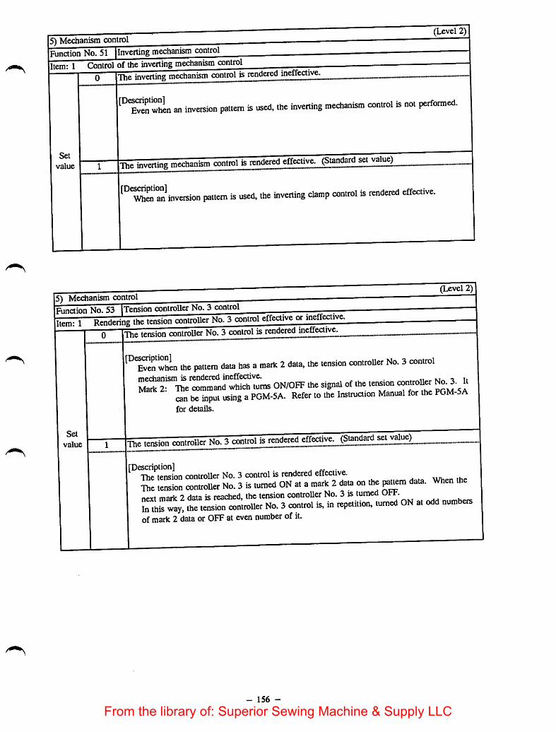
Set
value
an inversion pauem is used, .he inverting mechanism control is not performed.
Thsa ^nv.rting mechanism control is rendered effective. (Standard setjval^
inversion pattern is used, the inverting clamp control is rendered effective.
5) Medianism controlFunction No. 53 iTension controller No. 3 control
te^ng the tension controller No. 3control eiieaive or ineffective.
Set
value
''Tverwhin the pattern data has amark 2data, the tension controUer No. 3controlmechanism is rendered ineffective. . n kt^ i tiMark 2: Hie command which turns ON/OFF the signal of the tetsion poM si
can be input using aPGM-5A. Refer to the Instruaion Manual for the FGM-5Afor details.
The tension controller No. 3 control is rendered effective. (Standard set value)
[Description] ^ •The tension controller No. 3 control is rendered effective.the tension controller No. 3is turned ON at amark 2data on the ^uem data. When thenpvt mnrk 2 data is reached, the tension controller No. 3 is turned OFF.In this way, the tension contioUer No. 3control is, in repetition, turned ON at odd numbersofmark 2 data or OFF at even number of it.
- 156 -
From the library of: Superior Sewing Machine & Supply LLC

5) Mechanism control (Level 2)Function No. 55 [Buzzer controlItem: 1 Rendenng the sound of buzzer when accepting a key switch effective or ineffective
Set
value
0 The sound of buzzer is ineffeaive.
[Description]The buzzer does not sound when a key switch on the operation panel is pressed.
1 The sound of buzzer is effective.
[Description]The buzzer sounds when a key switch on the operation panel is pressed.
5) Mechanism control
Function No. 56 jSelection offloppy disk data reading sequence(Level 1)
Item: 1 Operation mode setting0-4
Set
value
(Standard set value ModeO) (AMS-215C priority mode)
[Description]A long time is retjuired to read data from a floppy disk because of difference andinterchangeabiUty of the floppy disks applicable to the AMS Series. Use this function tominimize the length oftime required to read data stored on a floppy disk.
[Data reading sequence]fflHIHIH]
rNormaUy disused.s J
Roppy disk for the AMS-215CFloppy disk for the AMS-B typeHoppy disk for theAMS-A type
Set valueData readingsequence
1 2 3
0 m ID m1 m m m2 m m3
- - -
4-
--
Note]Do not read data from the floppy disk for the AMS-215C, AMS-A or-B type model ofsewing machine with the function set at 3 or 4.
- 157 -
From the library of: Superior Sewing Machine & Supply LLC

6) Setting the delay time (Level 2)
Funaion No. 81 Wiper sweeping action (magnet)
Item: 1 The period of time during which the wiper (magnet) is energized and that required to reset the wiper arespecified.
Set
value
0-999 Period of time during which the wiper is energized (Standard set value T1 = 50 ms)
[Description]The length of time during which the wiper is in its ON state is specified.
Item: 2 The period of time required to reset the wiper (magnet) is specified.0-999 The periodof time required to reset the wiper (Standard set value T2 = 100 ms)
[Description]The length of time required to allow the machine to start the next operation from thecompletion of sweepingaction of the wiper can be specified. During the specified length oftime, other mechanisms are inoperative.
Wiper signal
Signal of other •mechanisms
TI
ON
- 158 -
Set value of item 1
T2 Set value of item 2
< Other mechanisms operate.
From the library of: Superior Sewing Machine & Supply LLC

6) Setting the delay time (Level 2)Function No. 82 Wiper sweeping action (air)
Item: 1 Hie period of time during which the wiper (air) is energized and that required to reset the wiper arespecified.
0-999 Period of timeduring which the wiperis energized (Standard set value T1 = 100 ms)
Set
[Description]The length of time during which the wiper is in its ON state is specified.
value
Item: 2 The period of time required to reset the wiper (air) is specified.0-999 The periodof time required to reset the wiper (Standard set value T2 = 100 ms)
[Description]The length of time required to allow the machine to start the next operation from thecompletion of sweeping action of the wiper can be specified. During the specified length oftime, other mechanisms are inoperative.
Ti Set value of item 1
ON
T2 Set value of item 2<
Signal of other ^ Other mechanisms operate.mechanisms
- 159 -
From the library of: Superior Sewing Machine & Supply LLC

Set
value
Item: 2
Function No. 84 jlntermediatc presscr action timingItem: 1 Lowering the intermediate presser ^.
0-999 Isetting the length of delay time after the inlermediaie presser has come down (ON timing)(Standard set value 50 ms)
s^ing mnchine starts running immediately after the intermediate presser has o^rated,the intermediate presser is likely to interfere with the needle bar since the intermediatepresser has amechanical delay. To prevent this, the sewing machine starts to run afterlength of time specified for this item has passed.
Raising the intermediate presserSetting the length of delay time after the intermediate presser has gone up (OFF timing)0-^)99
(Standard set value 150 ms)
'°1^hat"Lr actuates when the intermediate presser has not gone up to the highestthe former may interfere with the latter. To prevent this, the wiper actuates after the lengof time specified for this item has passed. During this period of time, neither the wiper northe feed actuate.
- 160 -
From the library of: Superior Sewing Machine & Supply LLC
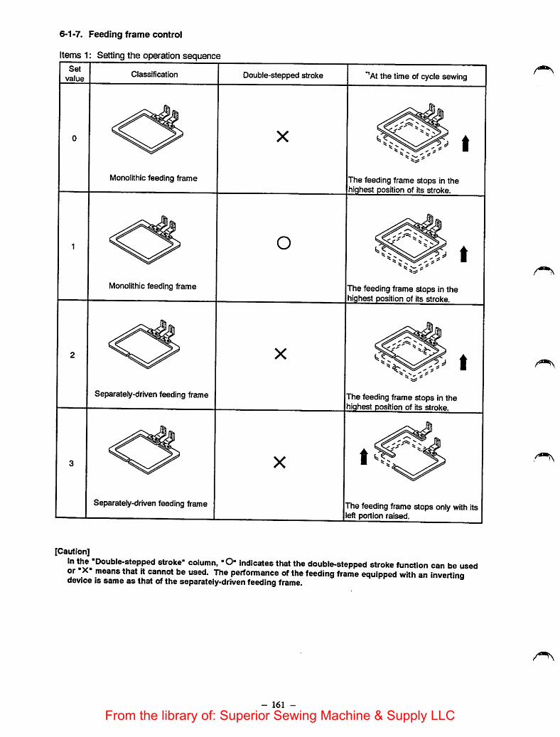
6-1-7. Feeding frame control
Items 1: Setting the operation sequence
Set
valueClassification Double-stepped stroke *^At the time ofcycle sewing
0
Monolithic feeding frame
X
The feeding frame stops in thehighest position of Its stroke.
1
Monolithic feeding frame
o
The feeding frame stops in thehighest position of its stroke.
2
Separately-driven feeding frame
X1
The feeding frame stops In thehighest position of Its stroke.
3
Separately-drivenfeeding frame
X
The feedingframe stops only with Itseft portion raised.
[Caution]In the '̂Double-stepped stroke" column, "O" indicates that the double-stepped stroke function can be usedor X" means that it cannot be used. The performance of the feeding frame equipped with an Invertingdevice Is same as that of the separately-driven feedingframe.
- 161 -
From the library of: Superior Sewing Machine & Supply LLC

Set
valueClassification Double-stepped stroke "^At the time of cycle sewing
4
Separately-driven feeding frame
X
The feeding frame stops only with itsright portion raised.
5
Separately-driven feeding frame
o
The feeding frame stops in thehighest position of its stroke.
6 o
Separately-driven feeding frame The feeding frame stops only with itsleft portion raised.
7
Separately-driven feeding frame
o
The feeding frame stops only with itsright portion raised.
- 162 -
From the library of: Superior Sewing Machine & Supply LLC

Set
valueClassification
Double-steppedstroke
*'Atthe time of cycle sewing**Feeding frame operation
controlled by the foot pedal
8
Separately-driven feeding frame
o
The feeding frame stops in thehighest position of its stroke.
The right portion of the feedingframe comes down first.
9
Separately-driven feeding frame
o
The feeding frame stops only withits left portion raised.
The right portion of the feedingframe comes down first.
10
Separately-driven feeding frame
o
The feeding frame stops in thehighest position of its stroke.
The left portion of the feedingframe comes down first.
11
Separately-driven feeding frame
o
The feeding frame stops only withits right portion reused.
The left portion of the feedingframe comes down first.
- 163 -
From the library of: Superior Sewing Machine & Supply LLC
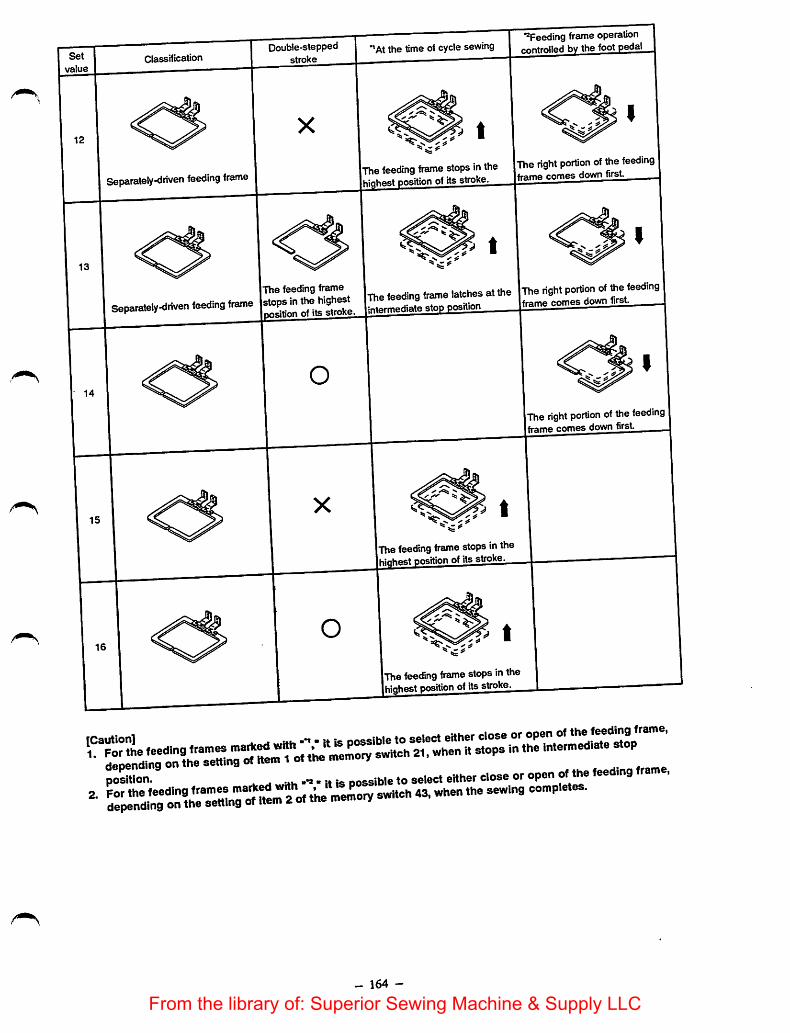
Set
valueClassification
Separately-driven feeding frame
Double-steppedstroke
*®Feeding frame operation•'At the time ofcycle sewing | bv the footpedal
,«ding tame etope in the The hght of dte (eedtngframe comes down firsthest positionof its stroke
latches atthe The right portion of the feedingThe feeding frameSppptaeiHHventeedingtame [etopsinttahighee. |The.eed.gtameiegtaeo
The feeding frame stopsinthehiqhest position ofitsstroke
The feeding frame stopsinthehighest positionof its stroke
The right portion of the feedingframe comes downfirst
^^^FoMhe feeding frames ®'°''
- 164 -
From the library of: Superior Sewing Machine & Supply LLC

6-2. Error messages
The error number oralphabets will beshown on the error number display of the operation panel to indicate thecondition of the machine.
Error No. Indicator lamp Error description Action to be taken
1
ONComes on if a malfunction has resulted in a
data read-out error.
Press the Set Ready Key to read out thedata again.
ON
The pattern No. indicatorlamp flashes on and off
Starts when there is no data for the relevantnumber.
Set the correct Pattern No.
Flash A floppy disk is no inserted. Insert a floppy disk.
2 ON
Comes on if the stitch length exceeds 12.7mm over the computable range in anattempt to enlarge a pattern based on thenumber of stitches.
Correctly reset the X- and/on Y-scale.
3 ON
Comes on if the needle is not in its highestposition.
Turn the handwheel until error No. "3"disappears. Or turn ON/OFF the NeedleThreading switch to raise the needle to itshighest position.
4 ON
Comeson if the maximum sewingarea(180mm X 110mm) is exceeded.
During a sewing cycle: Press the Returnto Origin key.While setting the 2nd origin: Press theJogkey.
5
Flash
Startswhen the temporary stop switch isturned ON.
Press thestartswitch to actuate thesewingmachine again. Tum ON/OFF the NeedleThreading switch, and the thread will betrimmed. (The lamp display changes from"Flash" to "ON".)
ON
Comes on when only the feeding frame ismoving. Comes on when the temporarystop switch is turned ON.
Turn ON thestart switch after pressing thereturn to origin and the forward orbackward switch.
6 ON
When large pattern data have been read ora complicated processing has been carriedout resulting in shortageof memory.
If the error has occurred when combiningsewing patterns, press theset ready switchor re-specify a scale.
7 ON
Comes on if a malfunction has caused themachine to lock, or if there has been afailure in the needle position detector.
Turn OFF the power switch. Replace thedefective parts or eliminate the cause ofthe machine locking. Then tum ON thepower switch.
8 ONComes on if a poor connection of asolenoid connector is detected.
Turn OFF the power switch, and check forthe loose solenoid connection.
9 ON
Comes on if the needle thread is broken. Re-thread the machine head, press thereturn to origin switch and the forward orbackward switdies to move thefeedingframe backward. Then press thestartswitch.
0
Flash
Starts when trying to format a floppy diskwith the write-protect tab in the openposition (the disk cannot be formatted).
Move the write-protect tab so that it is inits closed position.
ONComes on when trying to formatadefective floppy disk.
Replace the floppy disk.
A
ON
(Flash)
Air pressure is low.Air is not supplied to the sewing machine.Connector of the junction cable for the airvalve disconnects.
'Airpressure hasdropped during sewing.)
Turn OFF the power switch. Set the airpressure to 5-5.5 kgf/cm^ (0.5-0.55MPa).Connect the connector.
[Adjust theair pressure to thespecifiedvalue andre-start the sewing machine.)
E ONComes on when thesewingmachine rotatesn the reverse direction.
Turn OFF thepower switch. Change therotation direction of the motor.
- 165 -
From the library of: Superior Sewing Machine & Supply LLC

6-3. Changing the settings on the panel displaysSetting of the panel displays is allowed while the set readyindicator lamp is OFF. The set ready indicator lamp goesOFF when the set ready switch is pressed. After the setready indicator lamp goes OFF, settings on the paneldisplays can be changed through the setting switches,including the pattern No., X scale, Y scale, and counter.After completion of setting changes, press the set readyswitch again. This will cause the machine to automaticallyready pattern data from the micro floppy disk, compute thescale, move the feeding frame to the sewing start point (orthe 2nd origin), raise the feeding frame, and light the setready indicator lamp to tell that the machine is ready tostart sewing.Before starting pattern sewing, be sure to perform trialsewing to confirm that the programmed pattern stays withinthe sewing area of the feeding frame.
Updatingof panel
indication
^t Ready .indicator ON?
^fYESPress Set
Ready
Set Readyindicator
OFF?
Setpattern No.
NO
SetXscale.
SetYscale.
Setcounter.
Settingscorrect'
YES
NO
Press SetReady.
Read data
Scalecomputation
Feedingframe down
Materialfeed
Feedingframe up
Set Readyindicator ON?
Preparation ^completed .
6-4. Thread breakage detecting function
Thread take-up spring
Thread breakagedetecting plate
6-5. Temporary stop function
The thread breakagedetectordetects the breakageof theneedle thread by checking the contact between the threadtake-up spring and the thread breakageplate. Whilesewing, the motion of the thread take-up spring issynchronized with the motion of the needle bar. If theneedle thread is lost due to breakage, the thread plate whenit should leave the detecting plate. This makes it possibleto detect the thread breakage. Upon detection of the threadbreakage, the machine will slow down and trim the threadbefore it stops.The machinestops after it sews 10 stitches when the threadbreaksat sewing start, or after it sews 5 stitches when thethread breaks during a stitching cycle. Error No. "9" wiUbe indicated.
After re-threading the machine head, move the feedingframe forward or backward, using jog keys (y) or (A),and start switch to resume sewing, or move the feedingframe back to the sewing start by the return to originswitch.
This function is used to stop the feeding frame and thesewing mechanisms during a stitching cycle. When thetemporary stop switch is pressed during sewing, the errorNo. 5 flashes on and off on the display. Move the needlethreading switch up and down to allow the machine toperform thread trimming. The error No. indication on thedisplay will light up instead of flashing on and off. Referto the explanation of error No. 5 (on page 165.)
166 -
From the library of: Superior Sewing Machine & Supply LLC
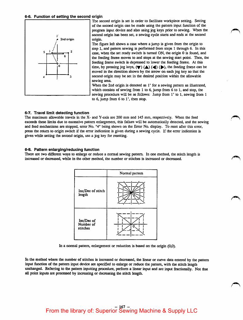
6-6. Function of setting the second originThe second origin is set in order to facilitate workpiece setting. Settingof the second origin can be made using the pattern input function of theprogram input device and also using jog keys prior to sewing. When thesecond origin has been set, a sewing cycle starts and ends at the secondorigin.The figure left shows a case where a jump is given from the origin tostep 1, and pattern sewing is performed from steps 1 through 6. In thiscase, when the set ready switch is turned ON, the origin 0 is found, andthe feeding frame moves to and stops at the sewing start point. Then, thefeeding frame switch is depressed to lower the feeding frame. At thistime, by pressing jog keys, (^) (A) (^) (•), the feeding frame can bemoved in the direction shown by the arrow on eadi jog key so that thesecond origin may be set in the desired position within the allowablesewing area.When the 2nd origin is denoted as 1' for a sewing pattern as illustrated,which consists of sewing from 1 to 6, jump from 6 to 1, and stop, thesewing procedure will be as follows: Jump from r to 1, sewing from 1to 6, jump from 6 to 1', then stop.
2nd origin
6-7. Travel limit detecting functionThe maximum allowable travels in the X- and Y-axis are 200 mm and 145 mm, respectively. When the feedexceeds these limits due to excessive pattern enlargement, this failure will be automatically detected, and the sewingand feed mechanisms are stopped, error No. "4" being shown on the Error No. display. To reset after this error,press the return to origin switch if the error indication is given during a sewing cycle. If the error indication isgiven while setting the second origin, use a jog key for resetting.
6-8. Pattern enlarging/reducing functionThere are two different ways to enlarge or reduce a normal sewing pattern. In one method, the stitch length isincreased or decreased, while in the other method, the number or stitches is inaeased or decreased.
Normal pattem
Inc/Dec of stitch
Tn\_w.length
w-
Inc/Dec ofNumber ofstitches
Tk• ' /t tX .iX
In a normal pattern, enlargement or reduction is based on the origin (0,0).
In the method where the number of stitches is increased or decreased, the linear or curve data entered by the patterninput function of the pattern input device are specified to enlarge or reduce the pattem, with thestitchlengthunchanged. Referring to the pattern inputting procedure, perform a linear input and arc input fractionally. Not thatall point inputs are processed by increasing or decreasing the stitch length.
- 167 -
From the library of: Superior Sewing Machine & Supply LLC

i»«»r-jsxrr~ r,;r;<r£rsi,achieved simply by pressing the set ready switch.[Catdion] which data has been stored in the machine using the back-up function, the
rprrMl n'̂ Clred '̂t^Se But note that if the back-up pattern is eniarged or reduced, thefloppy disk is required to be flnc/Dec of stitch iength or incrtJec of numberThe floppy disk is also required wheii the X/Y s h,,, .he oattern No., X/Y scale, and inc/Dec of
6-10. Max. sewing speed limit control knob
m
This control knob is used to specify the maximum sewingspeed. Normally, the sewing speed is automatically setaccording to the stitch length. ,If any lower speed is required, turn this knob counterclockwiseto obtain the desired sewingspeed. .Ifthe sewing speed is partly lowered, speed setting within t epattern is required. Use the PGM-5A.-nie chart shows the limitation ofthe maximum sewing speed.
- 168 -
From the library of: Superior Sewing Machine & Supply LLC
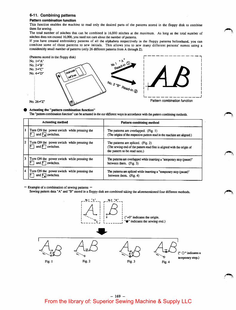
6-11. Combining patternsPattern combination function
This function enables the machine to read only the desired parts of the patterns stored in the floppy disk to combinethem for sewing.The total number of stitches that can be combined is 16,000 stitches at the maximum. As long as the total number ofstitches does not exceed 16,000, you need not care about the numberof patterns.If you have created embroidery patterns of all the alphabets respectively in the floppy patterns beforehand, you cancombine some of these patterns to sew initials. This allows you to sew many different persons' names using aconsiderably smallnumber of patterns (only 26 different patterns from A through Z).
(Patterns stored in the floppy disk)No. 1-^'A"
No. 2-^'B"
No. 3-^'C"
No. 4-i'D"
No. 26-^*Z" Pattern combination function
9 Actuating the "pattern combination function"The"paoem combination function" canbeactuated in the ourdifferent ways inaccordance with thepattern combining methods.
Actuating method Pattem combining method
1 Turn ON the power switch while pressingthe• and 1^ switches.
The patternsare overlapped. (Fig. 1)(The origins oftherespective pattem readin themachine arealigned.)
2 Turn ON the power switch while pressing theQ and 1^ switches.
The patterns are spliced. (Fig. 2)(The sewing endof thepattem readfirst isaligned with theorigin ofthe pattem to be read next.)
3 Turn ON the power switch while pressingtheQ and Q switches.
Thepatterns areovertyped while inserting a "temporary stop (pause)"between them. (Fig. 3)
4 Turn ON the power switch while pressing thep~[ and Q switches.
Thepattems arespliced while inserting a "temporary stop(pause)"between them. (Fig. 4)
— Example of a combination of sewing patterns —Sewing pattemdata "A" and "B"stored in a floppydisk are combinedtaking the aforementioned four differentmethods.
Na I *A' Na2 *B*
't-n < I("+0" indicates the origin.
bj I J indicates thesewing end.)
A8Fig. 2 Fig. 4
- 169 -
©"indicates a
temporary stop.)
From the library of: Superior Sewing Machine & Supply LLC
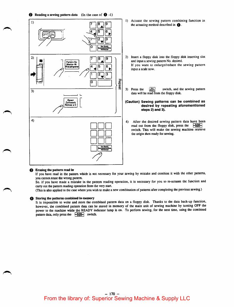
Reading a sewing pattern data (In the caseof 0-1)
1)
2)
3)
4)
B Pattern NoMuster-Nr
ITdeonfifntian
ResetZatlwerk
Remise a 0
0VklidMim
ana
•
• ••• ••• ••
r»ujuluitinn jVfttitfMion
g>
I) Actuate the sewing pattern combining function inthe actuating methoddescribed in O •
2) Insert a floppy disk into the floppy disk inserting slotand input a sewing pattern No. desired.If you want to enlarge/reduce the sewing patterninput a scale now.
3) Press the iay.j switch, and the sewing patterndata will be read from the floppy disk.
(Caution) Sewing patterns can be combined asdesired by repeating aforementionedsteps 2) and 3).
4) After the desired sewing pattern data have beenread out from the floppy disk, press the |' 5S •!switch. This will make the sewing machine retrievethe origin then ready for sewing.
0 Erasing the pattern read mIf you have read in the pattern, whidi is notnecessary for your sewing by mistake and combine it with the other patterns,you cannot erase the wrong pattern.So. if you have made a mistake in the pattern reading operation, it is necessary for you to re-actuate the function andcarry out the pattern reading operation from the very start.(This isalso applied tothe case where you wish tomake a new combination ofpatterns after completing the previous sewing.)
0 Storing the patterns combiiKd in memoryIt is impossible to write and store thecombined pattern data on a floppy disk. Thanks to the data back-up function,however, the combined pattern data can be stored in memory of the main unit of sewing machine by turning OFF thepower to the machine while the READY indkraior lamp is on. To perform sewing, for the next time, using the combinedpatterndata, only press the switch.
- 170 -
From the library of: Superior Sewing Machine & Supply LLC
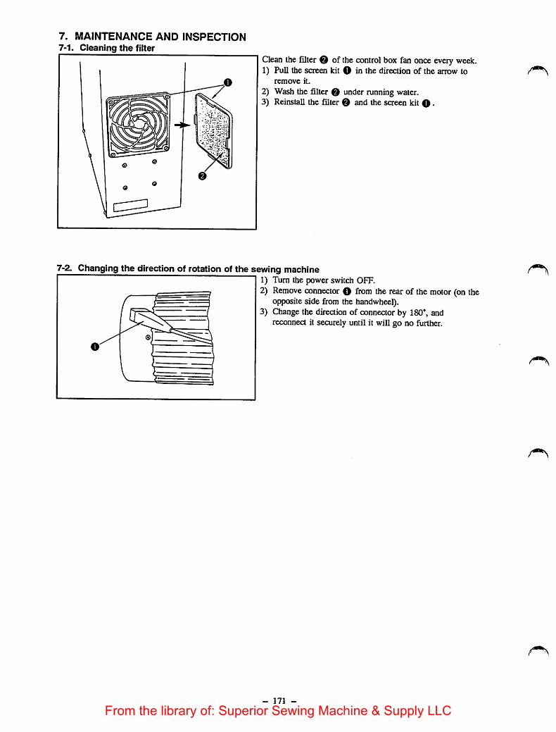
7. MAINTENANCE AND INSPECTION7-1. Cleaning the filter
(m
Clean thefilter of the control box fan onceevery week.1) Pull the screen kit O in the direction of the arrow to
remove it.
2) Wash the filter 0 under running water.3) Reinstall the filter 0 and the screen kit 0.
7-2. Changing the direction of rotation of the sewing machine1) Turn the power switch OFF.2) Remove connector O from the rear of the motor (on the
opposite side from the handwheel).3) Change the direction of connector by 180®, and
reconnect it securely until it will go no further.
- 171 -
From the library of: Superior Sewing Machine & Supply LLC

7-3. Replacing the fuseThe machine uses the following six fuses:
7A standard melting fuse for stepping motor (X)protection7A standard melting fuse for stepping motor (Y)protectionlOA standard melting fuse for stepping motorpowersupply protection7AT time-lag fuse for solenoid power supplyprotectionlAstandard melting fuse for 100 VAC power supplyprotection2Astandard melting fuse for marking light powersupply protection
replace a blown fuse, turn the power switch OFF,open the control box cover, and replace It with a newfuse with the specified capacity.
7-4. Adjustment and maintenance ofttie motors1. Adjusting the clutch gap
The clutch gap is factory-adjusted to03 mm.Readjust the clutchgap.
; ~ -I-"following results:a) The main motor is overheated.bl The motor fails to run smoothly-
% rrre 4- a. ... .0 s.Uo„^.
- 172 -
From the library of: Superior Sewing Machine & Supply LLC

<Adjusting procedure>
(1) For HITACHI motor
i f—r j 1VO Vj
o
0-^o
1) Turn the power OFF, confirm that the flywheel of themotor has completely stopped, then loosen setscrew Oto remove end cover 0 of the motor.
2) Remove the pulley cover, and then the V belt.3) Loosen locknut 0 using a spanner, insert L-shaped
wrench key O supplied with the motor into thehexagonal hole of setscrew 0.
4) Screw in the L-shaped wrench key in direction A asillustrated while turning the pulley by finger until theinertia of the pulley can not longer driver the pulley (inother words, until the pulley's resistanceis felt: 0 mmgap). Then, screw out the L-shaped wrench key indirection B for eight cooling fins 0 of the motor. (120degrees = 0.5 mm gap)
5) With thewrench key held in the position mentionedabove, tighten locknut 0 by a spanner with care takennot to move setscrew 0.
6) After adjustment, manually turn the pulley to check itfor smooth rotation. Turn the power switch ON, checkthe motor for proper operation, and carryout test run for20 to 30 times.
Gap; 0.5mm
Gap: 0
(2) For MATSUSHITA motorFirst, turn adjustment screw Q fully counterclockwise.Then, slowly turn it clockwise until resistance is felt.Further turn the adjusting screw clockwise by 8 steps(120 degrees).
- 173 -
From the library of: Superior Sewing Machine & Supply LLC

2. Replacing the clutch ring and brake ringWhen the clutch noise or brake noise has changed to a metallic noise after a long period of use, or when themotor has come to run unsmoothly, it is a sign of service life expiry of the frictional parts. Replace the clutchring and brake ring as follows:Turn the power OFF, and be sure that the motor has completely stopped before starting the replacement. (Waitfor 3 to 5 minutes after turning the power OFF.)
(1) For HITACHI motor
Clutch head
® 0
1) Remove the connector 4P from the controller.2) Remove the pulley cover and the V belt.3) Unscrew the three mounting screws of the clutch head to
remove the clutch head from the main body. (At thistime, take care not to allow the clutch head to fall.)
4) Remove C ring O-5) Take out spring bearing O, clutch resettingspring O,
clutch ring (E) >spline cap , and brake ring 0 .6) Using a rag moistened with benzine, clean the surfaces
of brake disk 0 and the clutch disk, and spline shaft
oIf the surfaces look brown, burnish the surfaces using acommercially available metal cleaner, then wipe themwith a rag moistened with benzine.(Do not touch the surface of the clutch or brake ring byhand, or do not clean it with benzine.)
- 174 -From the library of: Superior Sewing Machine & Supply LLC

(2) For MATSUSHITA motor
O €>
o X
1) Remove pulley cover O and belt O-2) Remove screw 0, and remove the clutch bracket from
the motor.
3) Remove screw 0 washer 0, presser disk 0, housingcover , spring 0 , clutch ring 0 , brake ring 0 ,and cushion 0 from clutch shaft 0 of the clutchbracket.
[Caution]Be careful not to lose cylindrical key 0 which fits inthe clutch shaft.
4) Replace with a new movable disk, then adjust the clutchclearance.
(3) Cleaning the spline assemblyQean the splines with a rag if they are dirty. Apply the grease supplied with the motor to a new ring. Use only"MOLY grease, and never use any other grease. Attach the connector from the clutch head to the PSCbox. Adjust the gap whenever the rings have been replaced.
3. Replacing the clutch disk• If the lining of the clutch rings has worn out to such an extent that the clutch disk comes in contact with the
metal part of the clutch ring, and burnishing with a commercially available metal cleaner can no longer correctit.
• When the clutch disk has worn out unevenly due to partial contact with the clutch ring.
- 175 -From the library of: Superior Sewing Machine & Supply LLC

<Repiacement procedure>
Rxing screw
Clutch disk
1) Remove the clutch head according to the previousparagraph, "Replacing the clutch ring and brake ring."
2) Loosen the four screws (M5xl2) retaining the clutchdisk, and remove the clutch disk.
3) Taking the faucet joint inside the vanes of the flywheelas the reference, fix a new clutch disk by alternatelytightening the four screws (M5xl2) gradually. At thistime, be very careful not to scratch the clutch disksurface to be in contact with the friaion plate.
4) Upon completion of the above step, turn the powerswitch ON, and check motor vibration before reinstallingthe clutch head. If the vibration issevere, remove theflxing screws again, turn the clutch disk 90 degreesagainst the flywheel, and reinstall the clutch disk so thatthe motor vibration is reduced to a minimum.
5) After the motor has completely stopped, reinstall theclutch head, using the three screws.
4. Replacing the brake disk
. ^ me brake disk has worn out unevenly due to partial txtntact with the brake ring.<RepIacement procedures
Brake disk
Pulleyside bracket
1) Remove the clutch head.2) Pull out the ring.3) Unscrew the three screws (M4xl2) retaining the brake
disk on the pulley side bracket to remove the brake disk.4) Install anew brake disk on the pulley side bracket by
gradually tightening the three fixing screws alternately.At this time, be very careful not toscratch the brakedisk surface which will contact the friction surface.
5) Finally, reinstall the ring before attaching the clutchhead to the main body.
- 176 -
From the library of: Superior Sewing Machine & Supply LLC

5. Cleaning the AlterIfthe filter is left clogged with fibrous wastes, the motor islikely to overheat, resulting in considerably shortedlifeof the lining. Qean the filter once a month or every othermonth.
/^\
7-5. Replacing the printed circuit boards
Types of printed circuit boards
O CPU circuit board (Control box)© I/F circuit board (Control box)
PMDC circuitboard (Control box)O POWER circuit board (Control box)0 Operating printed circuit board (Operation panel)0 Sensor printed circuit board (Sewing machine head)
O CPU circuit boardActs as the brain of the AMS-215C and outputs the control signals to control the floppy disk driver unit,sewing machine head, and the PGM-5A.
1) Turn OFFthe power switch. Then open the control boxcover.2) Remove all connectors (J13 through J17) from the CPU circuit board.3) Remove four setscrews retaining the circuit board. Then replace the CPU circuit board with a new one.4) Install the new CPU circuit board by reversing the above disassembly order. Pay attention toconnect the
connectors matching the numbers indicated on the circuit board and thenumbers attached to the connectors.[Caution]
The battery for thedata back-up is mounted onthe CPU circuit board. Be sure not to piace thecircuitboard on a metal piate or alike. Neverwrap the CPU circuit board with a sheet aluminum foil.
0 I/F printed circuit boardThe I/F circuit board receives the control signals from the CPU circuit board, and actuates the sewingmachine head and the PGM-5A.
1) Turn OFF the power switch. Then remove the control box cover.2) Remove the connectors J13, J14 and J15 from the CPU circuit board.3) Remove all connectors (J26 through J28, J32, J35 through J38; installed inside ofthe control box) (J31 and
J35; installed outside of thecontrol box) from the I/Fcircuit board.Connector for the synchronizer J31 and connector for the pneumatic solenoid drive are mounted on the wrongside of the circuit board, and designed to bedirectly connected with the connectors inserted from outside ofthe control box.
4) Remove six setscrews retaining the I/F circuit board so that the I/F circuit board is removed. Then replacethe circuit board with a new one.
5) Install the new I/F circuit board by reversing the above disassembly order.[Caution]
If the machine runs without J31 connector forthe synchronizer, the up position error "3" is not allowedto be reset.
if theJ31 connector for the pneumatic solenoid drive is not installed, the operating airpressure droperror "A" is not allowed to be reset.
- 177 -
From the library of: Superior Sewing Machine & Supply LLC

O PMDC circuit boardThe PMDC circuit board receives the stepping motordriving signals from the CPU circuit board through I/Fcircuit board, and acts to drive the sewing machine head, X and Y stepping motors.
1) Turn OFF the powerswitch. Then open the control box cover.2) Remove all connectors (J61 through J64) from the PMDC circuitboard.3) Remove six setscrews retaining the PMDC circuit board (the setscrews arealso used to fix the radiator from
outside of the control box) so that the PMDC circuit board is removed. Then replace the circuit board with anew one.
4) Install the new PMDC circuit board by reversing theabove disassembly order. Install the circuit board sothat the connector J62 is positioned at the top.
[Caution]Be sure to securely tighten the setscrews. The tightening torque has been specified to 14 kg at thetime of delivery.
O ROWER circuit boardThis circuit board supplies voltage to each unit in the control box.
1) Turn OFFthe power switch. Thenopen the control box cover.2) Remove all connectors (J51 through J59) from the POWER circuit board.3) Remove four setscrews retaining the power circuit board, bundle wire cover and POWER circuit board. Then
replace the circuit board with a new one.4) Install the new POWER circuit board by reversing the above disassembly order. Take care of connection of
the connectors.
[Caution]Time for discharge of eiectroiytic capacitor:For the normal use, the time for the discharge is about five seconds after the power switch has beenturned OFF.
If the poweris not supplied to the stepping motors or solenoids, about one and a half minutes will berequired for the discharge of the POWER circuit board only.
0 Operating printed circurt boardThis circuit board is fixed inside the control box. The switches, buzzers, and LEDs are mounted on it.
1) Turn OFF the power switch. Remove four setscrews from the control box rear cover.2) Remove the connector J61 fiom the operating circuit board.3) Remove six lode nuts for retaining the operating circuit board. Then remove the drcuit board and replace
with a new one.
4) Install the newopecatii^ circuit board by reversing the above procedure.
0 Sensor printed circuit boardThis drcuit board is used for thesewing machine head, and acts to detect the X origin and the travel limit.See Page 69 for the replacement.
- 178 -
From the library of: Superior Sewing Machine & Supply LLC
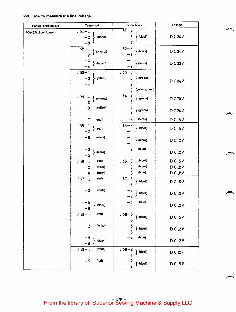
7-6. How to measure the line voltage
Printed circuit board Tester red Tester black Voltage
•
POWER circuit board J 51-1
-2
-3
1(orange) J51-4
-5
-7
1(black) DC 34 V
j J52-11 -2
y(orange) J 52-6
-7(black) DC 34 V
11CO
j. (brown) -6
-7j- (black) DC 33 V
J 53-1 ] J53-5 ]-3
-4
I (yellow) -6
-7
-8
I (green)
(yellow/green)
DC 34 V
J 54-1
-2J. (orange) J 54-4
-5} (green) DC 70 V
-3 (yellow) -4
-5j. (green) DC24V
-7 (red) -8 (black) DC 5V
J 55-1
-2}(red) J55-3
-5(black) DC 5V
1
! -61!
(white)-3-5
J. (black) D C12V
-3
-5J. (black) -7 (blue)
DC12V
J 56-1 (red) J56-6 (black) DC 5V
-2 (white) -6 (black) DC12V
i -6 (black) -3 (blue) DC12V
i J57-I11
(red) J 57-5
-6j- (black) DC 5V
-3 (white) -5
-6(black) DC12V
-5
-6j- (black) -4 (blue)
DC12V
J 58-1 (red) J 58-5
-6J. (black) DC 5V
-2 (white) -5
-6I' (black) D C 12 V
-5
-6j- (black) -4 (blue)
DC12V
J 59-1 (white) J59-2
-4j- (black) D C 12V
-5 (red) -2
-4y(black) DC 5V
- 179 -From the library of: Superior Sewing Machine & Supply LLC

Printed circuit board Tester red Tester blackVoltage
CPU circuit board J17-1
_ 3 (white)
-5 ^\ (black)
-6 J
JI7-5 1). (black)
-6 ^-5 y (black)-6 ^—4 (blue)
DC 5V
DCI2V
DC12V
PMDC circuit board ^ \ (orange)-2
3 (yellow)
- 7 fred)
J65-4 . , ,y (green)-5
—4 1 (green)—5
_ 8 (black)
DC 70 V
DC24V
DC 5V
l/F circuit board \ (orange)-6 J-1 (red)
_ 2 (white)
—9 I (black)-10''
J26-3 1-4 ^-9
y (black)-10-'
-9y (black)
-loJ- 8 (h'ue)
DC 33 V
DC 5V
D C12V
DCI2V
Connector Tester red Tester blackVoltage
J90
[Connector6P of the powersupply for the PGM-5A]
J 90 - I (red)
- 2 (white)
—4 (black)
J90-4 (black)
—4 (black)
- 3 (hloe)
DC 5V
DC12V
DCI2V
J40
[Connector6P of thetransformer secondary output]
J 40 -1 (gray)
- 3 (purple)
- 5 (black)
J40-2 (sray)- 4 (purple)
_ 6 (black)
AC 24 V
AC 50 V
ACIOOV
J85
[Connector2P of themarkinglightoutput]
J 85 - 1 (orange) J85-2 (orange) AC4.5V
- 180 -
From the library of: Superior Sewing Machine & Supply LLC
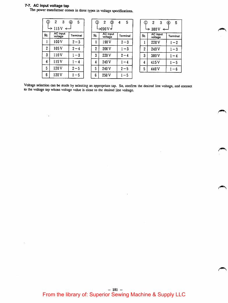
7-7. AC input voltage tapThe power transformer comes in three types in voltage speciflcations.
(D 2 3 (D 5
L> 115VNq
AC inputvoltage Terminal
1 lOOV 2-3
2 105V 2-4
3 llOV 1-3
4 115V 1-4
5 120V 2-5
6 130V 1-5
(D 2 (D
U20OVJ4 5
NqAC inputvoltage Terminal
1 190V 2-3
2 200 V 1-3
3 220 V 2-4
4 240 V 1-4
5 240 V 2-5
6 250 V 1-5
(D 2 3 ® 5
U 380V <—1No.
AC Inputvoltage Terminal
1 220V 1-2
2 240V 1-3
3 380 V 1-4
4 415V 1-5
5 440 V 1-6
Voltage selection can be made by selecting an appropriate tap. So, confirm the desired line voltage, and connectto thevoltage tap whose voltage value is close to the desired line voltage.
- 181 -
From the library of: Superior Sewing Machine & Supply LLC

00N)
) )
8. TROUBLES AND CORRECTIVE MEASURES
8-1. TVoubles and corrective measures (mechanical parts)
) ) )
Trouble Cause (I) Cause (2) Corrective measures
1. Mechanical lock 1-1) Impropcrnccdic-up position
1-2) Inconipletc return of the thread trimming cam shaft
1-3) Inaccurate positioning of the threadtrimming cam
1-4) Inaccurate positioning of the threadtrimmer solenoid bracket
1-5) The moving knife fails to movesmoothly.
1-6) Inaccurate initial positioning of themoving knife
1-7) Inaccurate positioning of the generatorstator
1-8) Inaccurate positioningof the handwhcel
Correct the stop position of the main shaft.
2-A) The thread trimmer follower sticksagainst the follower stopper
Correct the clearance between the thread trimmerfollower and the follower stopper.
2-B) The tension release arm sticks againstthe tension release shaft arm
Correct the clearance between the tension releasearm and the tension release shaft arm.
3-A) The marker line on the thread trimmingcam is not aligned with the marker lineon the main shaft.
4-A) The thread trimmer solenoid bracketcomes into contact with the threadtrimming cam (longitudinal direction).
4-B) The thread trimmer follower contacts .with the follower stopper and cannotrotate.
Accurately po<>ition the thread trimming cam.
Accurately position the thread trimming cam(longitudinal direction).
Accurately position the thread trimmer solenoidbracket (rotating direction).
Correct the blade pressure of the moving knife.
Correct the initial position of the moving knife.
Accurately position the generator stator.
Accurately position the handwheel.
From the library of: Superior Sewing Machine & Supply LLC
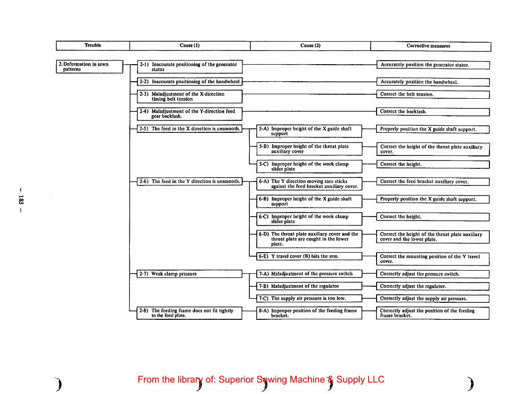
IVouble Cause (1) Cause (2) Corrective measures
2. Deformation in sewnpatterns
)
2-1) Inaccurate positioning of the generatorstator
2-2) Inaccurate positioning of the handwheel
2-3) Maladjustment of the X-directiontiming belt tension
2-4) Maladjustment of the Y-dircction feedgear backlash.
2-5) The feed in the X direction is unsmooth.
2-6) The feed in the Y direction is unsmooth.
2-7) Weak clamp pressure
2-8) The feeding frame does not fit tightiyto the feed plate.
5-A) Improper height of the X guide shaftsupport
S-B) hnproper height of the throat plateauxiliary cover
5-C) Improper height of the work clampslider plate
6-A) The Y direction moving race sticksagainst the feed bracket auxiliary cover.
6-B) Improper height of the X guide shaftsupport
6-C) Improper height of the work clampslider plate
6-D) The throat plate auxiliary cover and thethroat plate arc caught in the lowerplate.
6-E) Y travel cover (B) hits the arm.
7-A) Maladjustment of the pressure switch
7-B) Maladjustment of the regulator
7-C) The supply air pressure is too low.
8-A) Improper position of the feeding framebracket.
Accurately position the generator stator.
Accurately position the handwheel.
Correct the belt tension.
Correct the backlash.
Properly position the X guide shaft support.
Correct the height of the throat plate auxiliarycover.
Correct the height.
Correct the feed bracket auxiliary cover.
Properly position the X guide shaft support.
Correct the height.
Correct the height of the throat plate auxiliarycover and the lower plate.
Correct the mounting position of the Y travelcover.
Correctly adjust the pressure switch.
Correctly adjust the regulator.
Correctly adjust the supply air pressure.
Correctly adjust the position of the feedingframe bracket.
From the library of: Superior Sewing Machine & Supply LLC
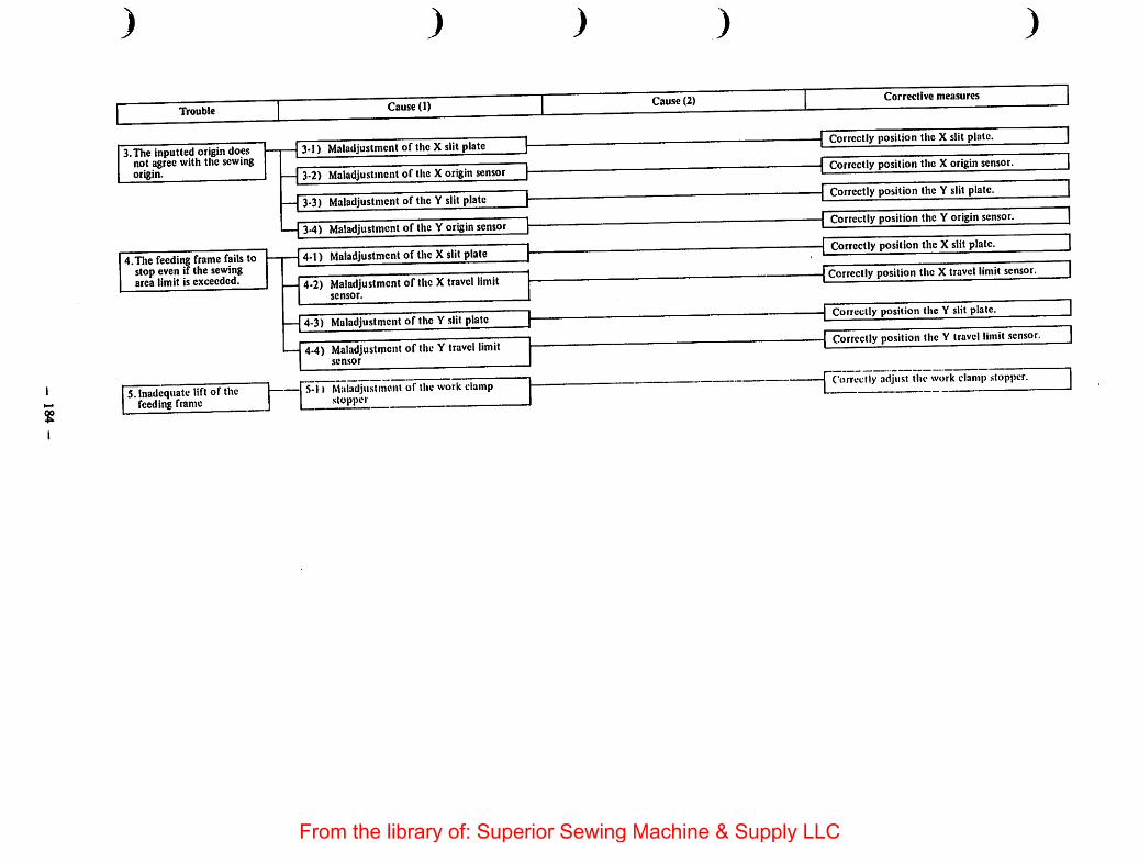
2
)
Trouble
3.The inputted origin doesnot agree with the sewingorigin.
4.The feeding frame fails tostop evenif the sewingarea limit is exceeded.
5. Inadequate lift of thefeeding frame
)
Cause (1)
3-1) Maladjustment of the X slit plate
3-2) Maladjustment of the X originsensor
3-3) Maladjustment of the Y slit plate
3-4) Maladjustmentof the Y origin sensor
4-1) Maladjustment of the X slit plate
4-2) Maladjustment of the Xtravel limitsensor.
4-3) Maladiustment of the Y slit plate
4-4) Maladjustment of theYtravel limitsensor
11 Italadjustmcnt of thework clampstopper
) ) )
Cause (2) Corrective measures
Correctly position the X slit plate.
Correctly position the X origin sensor.
Correctly position the Y slit plate.
Correctly position the Y origin sensor.
Correctly position the X slit plate.
Correctly position the X travel limit sensor.
Correctly position the Y slit plate.
Correctly position the Y travel limit sensor.
Correctly adjust the work clamp .stopper.
From the library of: Superior Sewing Machine & Supply LLC

00
Trouble Cause (1) Cause (2) Corrective measures
6. The feeding frame fails togo up.
7. The feeding frame failsto go down.
)
6-1) The supply air pressure is too low.
6-2) Maladjustment of the regulator
6-3) Maladjustment of the speed controller
6-4) Maladjustment of the pressure switch
6-5) Unsmooth motion the feed bracket,link and .slideplate
6-6) Malfunction of the solenoid valve
7-1) The supply air pressure is low.
7-2) Maladjustment of the speed controller
7-3) Maladjiistment of the pressure switch
7-4) Unsmooth motion of the feed bracketand link
7-S) Mairunction of the solenoid valve
)
Correctly adjust the supply air pressure.
Correctly adjust the regulator.
Correctly adjust the speed controller.
Correctly adjirst the pressure switch.
Apply grease.
A workpiece is not clamped by all the .surface ofthe feeding frame (uneven).
Replace the solenoid valve.
Correctly adjust the supply air prc.ssure.
Correctly adjust the speed controller.
Correctly ndjust the pressure switch.
Apply grease.
Replace the solenoid valve.
From the library of: Superior Sewing Machine & Supply LLC
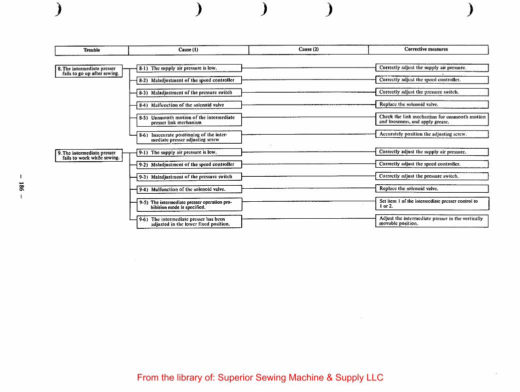
00OS
) ) ) ) )
Trouble Cause (1) Cau.se (2) Corrective measures
8.The intermediate presserfails to go up after sewing.
9.The intermediate presserfails to work while sewing.
8-1) The supply air pressure is low. Correctly adjust the supply air pressure.
— 8-2) Maladjustment of the speed controller Correctly adjust the speed controller.
8-3) Malad]u.slmenl of the pressure switch Correctly adjust the pressure switch.
— 8-4) Malfunction of the .solenoid valve Replace the solenoid valve.
8-S) Unsmooth motion of the intermediatepresser link mechanism
Check the link mechanism for unsmooth motionand looseness, and apply grease.
8-6) Inaccurate positioning of the intermediate pre.sser adjusting .screw
9-1) The .supply air pre.ssiirc is low.
9-2) Maladju.stmcnt of the speed controller
9-3) Maladjustment of the pressure switch
— 9-4) Malfunction of the solenoid valve.
Accurately position the adjusting screw.
Correctly adjust the .supply air prcs.surc.
Correctly adjust the speed controller.
Correctly adjust the pressure switch.
Replace the .solenoid valve.
9-5) The intermediate presser operation prohibition mode is specincd.
Set item 1 of the intermediate presser control to1 or 2.
9-6) The intermediate presser has beenadju.sted in the lower llxed position.
Adjust the intermediate pre.sser in the verticallymovable position.
From the library of: Superior Sewing Machine & Supply LLC

00-j
Trouble Cause (1) Cause (2) Corrective measures
10. Abnormal noise is heardfrom the face platecomponents.
11. The sewing machinestops immediately afterit is started.
12. The sewing machine failsto stop even if the needlethread breaks.
)
10-1) The clearance between the shuttle and theshuttle driver is too large.
Correct the clearance.
10-2) The positioning link docs not tightlyfit to the positioning pin while theintermediate presser works.
2-A) Inaccurate positioning of the intermediate presser rod bracket
Adjust the intermediate presser in the verticallymovable standard position.
10-3) The positioning link comes into contactwith the positioning pin and the intermediate presser .spring while themachine operates with the intermediatepresser fixed in the lower position.
10-4) The intermediate presser hits thethroat plate.
10-5) The intermediate presser hits the needlebar.
10-6) The intermediate presser hits the workclamp.
11-1) The machine head has not beenthreaded.
11-2) Inaccurate positioning of the threadbreakage detecting disk
12-1) Inaccurate positioning of the threadbreakage detecting disk
)
3-A) Inaccurate positioning of the intermediate rod bracket
4-A) Incorrect height of the intermediatepresser.
5-A) Incorrect height of the intermediatepresser.
.5-B) The intermediate presser operation prohibition mode is specified.
)
Adjust it in the standard position of the intcr-mediatc presser fixed in the lower position.
Correctly adjust the intermediate presser.
Correctly adjust the intermediate presser.
Set item I of the intermediate presser control toI or 2.
Correct the work clamp.
Thread the machine head.
Accurately position the thread breakagedetecting disk.
Accurately position the thread breakagedetecting disk.
)From the library of: Superior Sewing Machine & Supply LLC

0000
)
Trouble
13. The wiper cannotspreada thread.
14, Severe vibration
)
Cause (1)
13-1)The wiperhits the needle
) )
Cause (2)Corrective measures
l-A) Incorrect needle-up stop position. ] 1Correct the needle-up stop position.
l-B) Incorrect positioning ofthe wiper \ \ Correctly adjust the positioning ofthe wiper
)
13-2) The wiperhits the intermediatepresser.
2-A) Incorrect heightof the intermediatepresser
Correct the height of the intermediate presser.
2-B) Incorrect positioning of the wiper Correct the mounting position of the wiper
13-3) There is no clearance for the wiperbetween the needle and the intermediate presser.
3-A) The material thickness exceeds thelimit Dossiblc to use the wiper.
Tliewiperisadjusted to pass underthe intermediate pre.sser.
13-4) The wiperdoesnot workafter trimming a thread. ^
14-1) The sewing machine is not properlygrounded.
4-A) Thewiper switch has been set to OFF. Set the wiper switch to ON.
Securely fix the machine by the level adjuster.
Accurately adjust the belt tension.14-2) Maladjustment of the belt tension
Correct the position of the crank balancer.14-3) Inaccurate positioning of the crank
balancer
From the library of: Superior Sewing Machine & Supply LLC
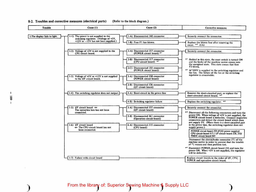
00VO
8-2. Troubles and corrective measures (electrical parts) (Refer to the block diagram.)
Trouble Cause (1) Cau,se (2) Corrective measures
1.The display fails to light.
)
1-1) The power is not supplied to theswitching regulator. (Voltage of +5V,+12V or -12V has not been .supplied.)
1-2) Voltage of +5V is not supplied to theCPU circuit board.
1-3) Voltage of +5V or +12V is not suppliedto the I/F circuit board.
1-4) The switching regulator docs not output.
1-5) 1/F circuit board **The operation box has not beenconnected.
1-6) I/F circuit boardThe CPU circuit board has notbeen connected.
1-7) Failure with circuit board
)
1-A) Disconnected J40 connector
1-B) Fuse F1 has blown.
2-A) Disconnected J57 connector(POWER circuit board) ♦'
2-B) Disconnected J17 connector(CPU circuit board) *'
2-C) Disconnected J55 connector(POWER circuit board)
3-A) Disconnected JS8 connector(POWER circuit board)
3-B) Disconnected J26 connector(I/F circuit board)
4-A) Short-circuit in the power line
4-B) Switching regulator failure
5-A) Disconnected J37 connector(I/F circuit board)
S-B) Disconnected J61 connector(Operation circuit board)
6-A) Disconnected J15 connector(CPU board)
)
Securely connect the connector.
Replace the blown fuse after removing thecause. (lA)
Securely connect the connector.
*' Molded in this .state, the reset switch is turned ONand the brake of the machine motor comes intothe energized state. This state causes that fuseF3 blows.
ACIOOV issupplied to theswitching regulator andthe fan. The lailure of the fan or the switchingregulator is conceivable.
Remove the short-circuited part, or replace theshort-circuited circuit board.
Replace the switching regulator. **
Securely connect the connector.
Disconnect all the following connectors and turn thefower ON. When voltage of +5V is not supplied, the
OWERcircuit board is defective. Connect respectiveconnectors and detect the circuit board which doesnot supply 5V. (When there is a short-circuited partin the power line, the switching regulator docs notsupply power.)
POWERcircuit board J59 (FDD power supply)/CPU circuit board J17 / I/F circuit board J28, J35/PMDC circuit board J6S
Disconnect the clutch/brake connector J71 of themachine motor in order to prevent that the troubleof *1 occurs and then perform test.
** Disconnect POWER circuit board J55 and turn thepower ON. When +5V is not supplied, the regulatorwill be defective.
Replace circuit Imards in the order of I/F, CPU,POWER and operation circuit board.
)From the library of: Superior Sewing Machine & Supply LLC

VOo
) ) ) ) )
Trouble Cau.se (1) Cau.se (2) Corrective measures
2.TI)e di.splays are confused.
3. A key switch on theoperation panel fails towork.
4. After the Set Ready switchis turned ON, the keys failsto work, but no errorindication is given.(The feeding frame docsnot go down.)(The sewing LED has notflashed.)
2-1) Voltage of +33V is not supplied to theI/F circuit board. (The normal resetsignal is not outputicd.)
2-2) The reset signal is not transferred.(I/F" circuit board CPU circuit board)
2-3) i-'ailurc with circuit board
3-1) I'ailure with the switch
— 3-2) Failure with the circuit board
4-1) The signal for the feeding frame drivingis not transferred. (CPU circuit board-» I/F circuit board)
— 4-2) l-ailure with the circuit board
l-A) Disconnected J51 connector(POWFR circuit board)
1-B) Disconnected J52 connector(POWFR circuit board)
1-C) Disconnected J28 connector(I/I-' circuit board)
1-D) Fuse l'3 lias been blown.
2-A) Disconnected J14 connector(CPU circuit board)
2-D) Disconnected J24 connector(I/F circuit board)
l-A) Disconnected J13 connector(CPU circuit board)
1-B) Disconnected J23 connector(I/F circuit board)
Securely connect the connector.
Remove the cause and replace the blown fuse ._ —
(7AT)
Securely connect the connector.
Replace circuit board in the order of I/F andCPU circuit board.
F.xecute the input check program to identify thedefective switch, and replace the switch or theoperation circuit board.
Replace circuit boards in the order of I/F andCPU circuit board.
Securely connect the connector.
Replace circuit boards in the order of I/F andCPU circuit board.
Thepower supply fordriving the machine head solenoid (thread trimmer solenoid, wiper solenoid) and the machine motor(clutch, brake) and the power supply for the air cylinder and driving thesolenoid valve.The reduction of the solenoid resistance value-»The damageof the driving transistor on the I/F circuit board is conceivable.Measure the .solenoid re.sistance value.
** The feeding frame islowered and theorigin retrieval isperformed. However, J13 connector iset|uippcd with thesignal forpre.sser foot driving and the pulse motordriving, so the machine doesnot work. I-rrors arc not also ontputted.
From the library of: Superior Sewing Machine & Supply LLC

I
Trouble
5. After the Set Ready switchis turned ON, the feedingframe comes down but
mlfails to move.
)
Cause (I)
5-1) Voltageof+33V is not supplied to thePMDC circuit board.
5-2) I/F circuit board PMDCcircuit boardcannot be connected.
5-3) PMDC circuit board «• X side pulsemotor are not connected.
5-4) The power is not supplied to the X sidepulsemotor.
5-5) Failure with the circuit board
)
Cause (2)
I-A) Disconnected J53 connector(POWER circuit board)
1-B) Disconnected J54 connector(PMDC circuit board)
1-C) Disconnected J65 connector(PMDC circuit board)
1-D) Fuse F2 has blown.
2-A) Disconnected J36 connector(I/F circuit board)
2-B) Disconnected J24 connector(PMDC circuit board)
3-A) Disconnected J63 connector(PMDC circuit board)
3-B) Disconnected J74 (blue) connector(Inside the table stand)
4-A) Fuse F2 has blown.(PMDC circuit board)
Corrective measures
Securely connect the connectors.
Remove the cause and replace the blown fuse.(lOA)
Securely connect the connectors.
Replace the blown fuse after removing thecause. (7A)
Replace the PMDC circuit board.
It is tried to move the feeder to the X travel limit in order to correct the retainer after the power supplyhas been turned ON.
*• Thepower issupplied to both Xand Yaxes by this. Check the current adjusted value axis on the PMDCcircuit board.
♦* Tlic power issupplied to the Xaxis pulse motorby this. Check thecurrent adjusted value in the Xaxison the PMDC circuit board. When the power is supplied to and ♦*, it is the failure with the circuitboard if the Rises blow immediately.
) ) )From the library of: Superior Sewing Machine & Supply LLC

)
6.The feeding irame movesonly to the X direction andstops.
)
Cause (1)
6-1) PMDC circuit board - Y axis pulsemotor have not been connected.
) )
Cause (2)
1-A) Disconnected J64 connector(PMDC circuit board)
1-D) Disconnected J75 connector(Inside the table stand)
)
Securely connect the connectors.
6-2) Thepower is not supplied to the Y-axispulse motor.
2-A) Fuse F1 has blown.(PMDC circuit board)
Replace the blownfuseafter renroving the cause.(7A)
— 6-3) Failure with the circuit boardReplace the PMDCcircuit board.
7.The correction of theretainer stops on the waywhile the power supply isturned ON. (It is impossible to detect theorigin.
7-1) The signal of the machine head sensorhas not been normally inputted.
1-A) Failure with the machine head sen.sor Detect the defective sensor using the input checkprogram and replace the defective sensor afterconfirming the connector.
Set the switch to OFF.8.The feeding frame fails to
go up when it reaches thesewingstart point.
8-1) The machine has been set to the bobbinwinding mode.
1-A) The bobbin winder switch (speed VR)has been set to ON.
1-B) The bobbin winder switch isdefective. Replace the defectiveswitch after checking thefailure using the input check program.
1 1. • 1 rvr*rr
8-2) The machine hasbeenset to the machinethreadingmode. (The intermediate
2-A) The machine threader switch has been.set to ON.
—-— Set the switch to OPF.
2-B) The threader switch is defective. Replace the defective switch after checkingthefailure the input check program.
— 8-3) Failure with the circuit boardReplace the defective circuitboards in the orderof I/F and CPU circuit boards.
»'® After detecting the Xtravel limit bythe correction of the retainer, the feeding frame tries to move to
♦" The'p'owcr"is supplied to the Yaxis pulse motor by this. Check the current adjusted value in the YWhen'the'pow^r^^ t°urncd ON. it is the failure with the circuit board if the fuse blows immediately.
From the library of: Superior Sewing Machine & Supply LLC

Tix>uble Cause (1) Cause (2) Corrective measures
9. The feeding frame switchfails to work.
10. The sewing macliine failsto start sewing, and onlythe feed mechanism isactuated when the startswitch is depressed.
11. Error No."1 LIGHTING" isindicated.(Floppy read error)
)
9-1) Pedal switch I/F circuit board havenot been connected.
9-2) Failure with the pedal switch
9-3) Failure with the circuit board
10-1) The machine has been set to the stopmode.
10-2) Failure with the circuit board
11-1) The floppy di.sk is defective.
— 11-2) Failure with FDD
11-3) The circuit board is defective.
)
1-A) Disconnected J21 connector(1/F circuit board)
1-B) Disconnected J88 connector(Control box)
1-A) The machine ON/OFF switch has beenset to OFF'.
1-B) Disconnected J38 connector(I/F circuit board)
1-C) The machine ON/OFF switch isdefective.
Connect the connector.
Replace the switch after checking the failureusing the input check program.
Replace the circuit boards in the order of I/F andCPU circuit boards.
Set the machine ON/OFF switch to ON.
Connect tiie connector.
Replace the switch after checking the failureusing the input check program.
Replace the circuit boards in the order of 1/Fand CPU circuit boards.
Replace the floppy disk. *''
Replace FDD.
Replace the CPU circuit board.
For the important data, make the master disk and save them at least in two disks.
) ) )From the library of: Superior Sewing Machine & Supply LLC
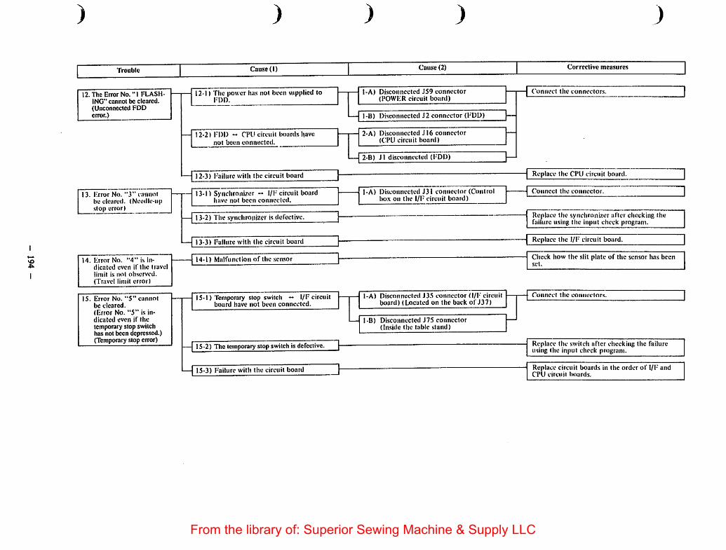
so
)
Trouble
12. The Error No. "I FLASHING" cannot be cleared.(Unconnected FDDerror.)
13. iirror No. "3" cannotlie cleared. (Needle-upslop error) _
14. Error No. "4" is indicated even if the travellimit is not observed.(Travel limit error)
15. Error No. "5" cannotbe cleared.(Error No. "5" is indicated even if thetemporary stop switchhas not been depressed.)(Temporary stop error)
)
Cause (1)
12-1) Tiic power lias not been supplied tol-DD.
12-2) IM)U « CPU circuit boards havenot been connected.
12-3) I'ailurc with tjic circuit board
13-1) Synchronizer l/F circuit boardhave not been connected,
13-2) The synchronizer is defective.
—|~r3-3) Failure with the circuit board
14-1) Malfunction of the sensor
15-1) Temporaiy stop switch « I/F circuitboard have not been connected.
— 15-2) The temporarystop switch is defective.
15-3) F-ailure with the circuit board
) )
Cause (2)
1-A) Disconnected J59 connector(POWER circuit board)
1-B) Disconnected J2 connector (FDD)
2-A) Disconnected JI6 connector(CPU circuit board)
—I 2-B) Jl disconnected (l-'DD)
j-A) Disconnected J31 connector (Controlbo.x on the l/F circuit board)
I-A) Disconnected J35 connector d/l' circuitboard) (Located on the back of J37)
l-B) Disconnected J75 connector(Inside the table stand)
)
Corrective measures
Connect the connectors.
Replace the CPU circuit board.
Connect the connector.
Replace the synchronizer after checking thefailure using the input check program.
—{ Replace the l/F circuit board.
Check how the slit plate of the sensor has beenset.
Connect the connectors.
Replace the switch after checking the failureusing the input check program.
Replace circuit boards in the order of I/I- andCPU circuit boards.
From the library of: Superior Sewing Machine & Supply LLC

VOu»
Trouble Cause (1) Cause (2) Corrective measures
16. The sewing machine failsto start, and the errorNo. "7" is given when .the start switch is depressed. (Machine lock error)
17. The machine rotates athigh speed, and error No."7" is indicated.(Machine lock error)
18. Error No. "8" cannot becleared. (Disconnectedconnector error)
16-1) The machine belt has not been set.
16-2)Machinc motor « I/F circuit boardhave not been connected.
16-3) The power has not been supplied to themachine motor.
16-4) Failure with the circuit board
17-1) The synchronizer is defective.
17-2) Failure with the circuit board.
18-1) The thread trimmer solenoid I/Fcircuit board have hot been connected.
18-2) Failure with the circuit board
)
2-A) Disconnected J30 connector(I/F circuit board)
2-B) Disconnected J71 connector(Machine motor clutch/brake)
3-A) Disconnected J72 connector(Machine motor power supply)
1-A) Disconnected J32 connector(I/F circuit board)
1-B) Disconnected J77 connector(Control box)
1-C) The thread trimmer solenoiddisconnected
) )
Attach the belt.
Connect the connectors.
Replace the 1/F circuit board.
Replace the synchronizer after checking thefailure using the input check program.
Replace the I/F circuit board.
Connect the connectors.
Replace the solenoid after checking thedisconnection by a tester.
Replace the I/F circuit board.
)From the library of: Superior Sewing Machine & Supply LLC

VOo\
)
Trouble
19. Tlic thread breakagedetector fails to work.(The 8 stitches at sewingstart and the stitcheswithin 3 stitches in sew-ingcannot be detected.)
20. Error "A" cannot becleared.(Air pressure drop error)
21. Others
)
Cause (1)
19-1) The machine has beenset to the threadbreakage detection ineffecivemode.
19-2) TIte machine head has not beengrounded.
19-3) Failure with the circuit board
) )
Cause (2)
I-A) Item 1of memory switch No. 47 is set to"O".
)
Set item I of memory switch No. 47 to "1".
Check the grounding conductor of the machinehead and connect it.
Replace the I/F circuit board.
Replace the I/F circuit board.19-4) Failure with the circuit board.
20-1) Air sen.sor «• I/F circuit board have notbeen connected.
— 20-2) Failure with the air sensor
—[20-3) Failure with the circuit board
21-1) The machine operation mode isimproper
1-A) Disconnected J34 connector (1/F circuitboard, control box)
1-B) Disconnected J79 connector
Connect the connectors.
Replace the air sensor after checkingthe failureusingthe input check program.
Replace the circuit boards in the order of I/Fand CPU circuit boards.
Check the setting of the memory switches arc set.
Set the rotary SW2 for the test mode selection onthe I/F circuit board to "0".21-2) The machine has been set to the test
mode.
21-3) Failure with the circuit boardDefects of the feed mechanism:
Replace the circuit boards in the order ofPMDC, POWER and I/F circuit boards.
Defects other than the feed mechanism:Replace thecircuit boards intheorder of I/Fand CPU circtiit boards.
From the library of: Superior Sewing Machine & Supply LLC
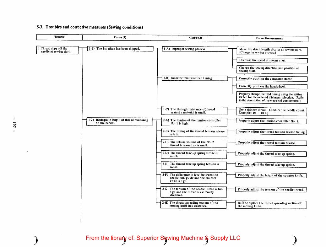
VO-o
8-3. Troubles and corrective measures (Sewing conditions)
Trouble Cause (1) Cau.sc (2) Corrective measures
I.Thread slips off theneedle at sewing start.
)
1-1) The ht stitch has been skipped.
1-2) Inadequate length of thread remainingon the needle.
)
1-A) Improper sewittg process
1-B) Incorrect material feed timing
I-C) The through resistance of^threadagainst a material is small.
2-A) The tension of the tension controllerNo. 1 is high.
2-B) The timing of the thread tension releaseis late.
2-C) The release volume of the No. 2thread tension di.sk is small.
2-D) The thread take-up spring stroke ismuch.
2-Ii) I'he thread take-up spring tension isweak.
2-1*) The difference in level between theneedle hole guide and the counterknife is high.
2-G) The tension of the needle thread is toohigh and the thread is extremelystretched.
2-H) The thread spreading section of themoving knife has scratches.
) )
Make the stitch length shorter at sewing start.(Change in sewing process)
Decrease the speed at sewing start.
Change the sewingdirection and position atsewing start.
Correctly position the generator stator.
Correctly position the hamlwliccl.
Properly changethe feed timing usingthe settingswitch for the material thickness selection. (Referto the description of theelectricalcomponents.)
lJ.sea thinner thread. (Reduce the needle count.Plxample: #4 - #11.)
Properly adjust the tension controller No. I.
Properly adjust the thread tension release timing.
Properly adju.st the thread tension release.
I Properly adjust the thread take-up spritig.
Properlyadjust the thread take-upspring.
Properly adjust the height of the counter knife.
Properly adjust the tension of the needle thread.
Buff or replace the thread spreading section ofthe moving knife.
)From the library of: Superior Sewing Machine & Supply LLC

vo00
)
Trouble
)
Cause (1)
1-3) Itiadcquale remaining Icngtli of thebobbin thread
1-4) A workpiece is liable to becomeunstable.
1-5) The needle bar thread guide has beenerroneously threaded.
1-6) The bobbin thread conies out of thewrong part of the bobbin case becauseof the idling of the bobbin.
) )
Cause (2)
3-A) The difference in level between theneedle hole guide and the counterknife is high.
3-B) The clearance between the needle holeguide and the counter knife is .small.
3-C) The bottom of the needle hole guidehas .seratchcs.
)
Corrccilve measures
Properly adjust the height of the counter knife.
Properly adjust the position of the counter knife.
Duff or replace the needle hole guide.
3-D) The thread .spreading section of themoving knife has scratches.
Buff or replace the thread spreading .section ofthe moving knife.
3-E) The shuttle raec spring has .scratches.
3-F) The tension of the bobbin thread is toostrong.
4-A) The intermediate presser is high.
4-B) The stroke of the intermediate presseris large.
4-C) Maladjustment of the intermcdiatt:presser phase
4-D) The feeding frame is apart from thesewing position at sewing start.
Remove the scratches or replace.
Property adjust the tension of the bobbinthread.
Properly adjust the height of the intermediatepre.sscr.
-{ Decrease the stroke of the intermediate presseTT
Clorrectly adjust the phase of the intermediatepresser.
Bring the feeding frame near to the sewingposition at sewing start.
Make the feeding frame according to the sewingprocess.
Remove the loosenc.ss of the workpiece.
See "How to thread the needle bar threadguide."
Use the bobbin and the bobbin case exclusivelyused for the AMS-2I5C.
From the library of: Superior Sewing Machine & Supply LLC

VOVO
Trouble Cause (1) Cause (2) Corrective measures
2. Needle breakage 2-1) Maladjustment of the clearance betweenthe needle and the shuttle driver
Correct the clearance between the needle andthe shuttle driver.
)
2-2) Maladjustment of the clearance betweenthe needle and the shuttle
2-3) Incorrect feed timing
2-4) The needle hits the moving knife.
2-5) The needle hits the intermediate presser.
2-6) The needle hits the wiper.
2-7) The needle is bent.
2-8) The needle is thin.
2-9) The thickness of the workpiecc exceedsthe specified thickness.
2-10) The needle hole guide has scratches.
) ) )
Correct the clearance between the needle and theshuttle.
Correct the position of the generator stator.
Correct the position of the handwhcel.
Properly change the feed timing using the settingswitch for the material thickness selection. (Referto the description of the electrical components.)
Correct the position of the moving knife.
Accurately position the intermediate presser barbracket.
Correct the needle-up stop position.
Accurately position the wiper.
Replace the needle.
Change the needle count according to the work-piece.
The tjiickncss possible to sew: 5 mm max.
Remove the scratches or replace.
)From the library of: Superior Sewing Machine & Supply LLC
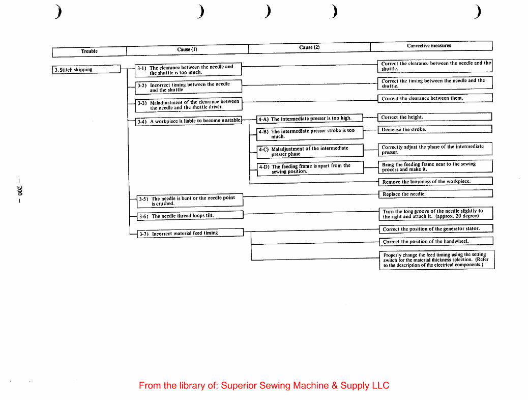
tooo
) ) ) ) )
Trouble Cause (1) 1 Cause (2) 1 Corrective measures |
3.Stitch skipping 3-1) Theclearance between the needle andthe shuttle is too much.
3-2) Incorrect timing between the needleand the shuttle
3-3) Maladjustment of the clearance betweenthe needle and theshuttle driver
3-4) Aworkpiece isliable to become unstable.
3-5) The needle is bent or the needlepointis crushed. ^
3-6) The needle thread loops tilt.
3-7) Incorrect material feed timing
4-A) The intermediate presser is too high.
4-B) The intermediate presserstroke is toomuch.
4-C) Maladjustment of the intermediatepresser phase
4-D) The feeding frame isapart from thesewing position.
Correct the clearance between the needle and theshuttle.
Correct the timing between the needle and theshuttle.
Correct the clearance between them.
Correct the height.
Decrease the stroke.
Correctly adjust the phase of the intermediatepre.sscr.
Bring the feeding frame near to the sewingprocessand make it.
Remove the looseness of the workpiece.
•j Replace the ncedliT
Turn the long groove of the needle slightly tothe right and attach it. (approx. 20 degree)
Correct the position of the generator stator.
Correct the position of the handwheel.
Properly change thefeed timing using thesettingswitch for the material thickness selection. (Referto the description of theelectricalcomponents.)
From the library of: Superior Sewing Machine & Supply LLC
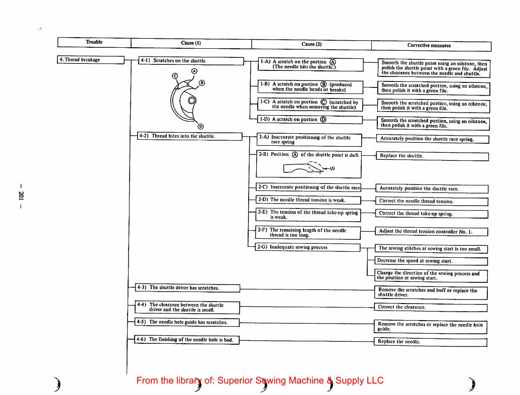
Trouble
4.Tl)rcad breakage
)
Cause (1)
{4-1) Scratches on the shuttle
4-2) Thread bites into tlic shuttle.
— 4-3) The shuttle driver has scratches.
4-4) The clearance between the shuttledriver and the shuttle is small.
— 4-5) The needle hole guide has scratches.
— 4-6) The finishing of the needle hole is bad.
)
Cause (2)
1-A) Ascratch on theportion @(The needle hits the shuttle.)
1-B) Ascratch on portion (B) (producedwhen the needle bends or breaks)
1-C) Ascratch on portion © (scratched bythe needle when removing the shuttle)
1-D) Ascratch on portion (§)
2-A) Inaccurate positioning of the shuttlerace .spring
2-B) Position (§) of the .shuttle point isdull.
2-C) Inaccurate positioning of the shuttle race
2-D) The needle thread tension is weak.
2-E) The. tension of the thread take-up springis weak.
2-F) The remaining length of the needlethread is too long.
2-G) Inadequate sewing process
)
Corrective measures
Smooth the shuttle point using an oilstone, thenpolish the shuttle pointwith agreen file. Adjustthe clearance between the needle and shuttle.
Smooth the scratched portion, using an oilstone,then polish it with a green file.
Smooth the scratched portion, using an oilstone,then polish it with a green file.
Smooth the scratched portion,using an oilstone,then polish it with a green file.
Accurately positionthe shuttle racespring.
Replace the shuttle.
Accurately position the shuttle race.
Correct the needle thread tension.
Correct the thread take-up spring.
Adjust the thread tension controller No. 1.
The .sewing stitches at sewing .start is too small.
Decrease the speed at sewing .start.
Changethe direction of the sewingprocessandthe position at sewing start.
Remove the scratches and buff or replace the
— Correct the clearance.
Remove the scratches or replace the needle holeguide.
Replace the needle.
From the library of: Superior Sewing Machine & Supply LLC

8N)
)
Trouble
5.Thread breaks at the timeof thread trimming.
)
Cause (1)
4-7) The thread path of the intermediatepresser has scratches.
4-8) The needle hits the intermediate prcsscr.
4-9) Maladjustment of the thread take-upspring
4-10) Unsmooth rotation of the shuttle
5-1) Incorrect tension release timming
5-2) The thread spreading section of themoving knifehasscratches.
5-.1) The shuttle race spring has scratches.
5-4) The difference in level between theneedle hole guide and the counterknife is too high.
5-5) The clearance between the needle holeguide and the counter knife is small.
5-6) Thebottom of the needle hole guidehas scratches.
5-7) Incorrect thread spreading timingofthe moving knife
5-8) The needle thread tension is too high.
5-9) The stroke of the thread take-up strokeis small.
5-10) The tension of the thread take-upspring is too high.
) )
Cause (2)
)
Corrective measures
Polish it with a green file or replace.
Correct the position and height of the intermediate presser bracket.
9-A) The stroke of the thread take-up springis too large.
9-0) The tension of the thread take-up springis too strong.
I^C'oireclly adjust the thread take-up spring.
QO)r!vctiy avijusi the tiiread take-up spring.
10-A) Fibrous wa.stcs on the shuttle race
— 10-0) Lack of lubrication
1-A) The tension release timing is too late.
1-B) The release volume of the thread tensiondisk No. 2 is .small.
4-A) The counter knife falsely cuts threadbefore the thread is trimmed by themoving knife blade.
5-A) The counter knife falsely cuts threadbreakage before the thread is trimmedbythe moving knife blade.
6-A) Thread is falsely cut by the needle holeguide.
Remove the shuttle, and remove the fibrouswastes.
Lubricate the shuttle assembly.
Correct the tension release timing.
Correctly adjust the thread tension release.
Polish the moving knife with a green file.
Correct the height of the counter knife.
Correct the position of the counter knife.
Polish or replace the needle hole guide.
Correct the initial position of the thread trimming cam and the moving knife.
Correct the needle thread tension.
Correct the thread take-up spring.
Correct the thread take-up spring.
From the library of: Superior Sewing Machine & Supply LLC

too
Trouble Cause (1) Cause (2) Correclive measures
6.Thread trimming failure
)
6-1) The thread trimmer is dull.
6-2) Tlircad wastes arc left in the sluittlecover.
6-3) The moving knife fails to spread thethread.
6-4) Skipping of the last stitch
6-S) The bobbin thread cannot be trimmed.
6-6) Incorrect needle-up stop position
)
1-A) The moving knife and/or counter knifehas worn out.
Replace the moving knife and/or counter knife.
I-B) The moving knife and counter knifefail to overlap properly.
Correct the height and position of the movingknife and counter knife.
1-C) The counter knife blade is not parallel.
— i-D) Incorrect position of the counter knife.
2-A) Presence of a burr on portion of themoving knife (I'lie shape of trimmedthread will be " " , andthread wastes are left.)
2-B) Pre.sence of scratches on the shuttle racespring (The shape of trimmed threadwastes arc left.)
3-A) Incorrect initial position of the movingknife
3-B) Incorrect path of the moving knife
3-C) Inaccurate positioning of the threadtrimming cam
3-D) Inaccurate positioning of the shuttle racespring
4-A) Incorrect timing and clearance betweenthe needle and shuttle
4-B) Incorrect height of the intermediateprcsscr
4-C) Tilting of the needle thread loop
S-A) The last sewing stitch is small.
S-B) Bobbin thread tension is weak.
5-C) The needle hole guide diameter is large.
) )
Adju.sting the parallelism of the blade tip ofthe counter knife.
Correct the position of the counter knife.
Remove the burr(s) using a green file, or replacethe moving knife.
Remove the scratches.
Correct the initialposition of the moving knife.
Replace the moving knife or the throat plate.
Accurately position the thread trimmingcam.
Accurately position the shuttle racespring.
Correct the timing and the clearance.
Correct the height.
Attach the needle turning its long grooveslightly to the right (approx. 20 degree).
Make the last stitch length I mm or more.
Decrease the thread tension.
Change it to the part of its smaller needle hole.
Correct the needle-up stop position.
)From the library of: Superior Sewing Machine & Supply LLC

lO
2
Trouble
7. Loose stitch
)
Cause (1)
7-1) Maladjustment of thethread tension
) )
Cause (2)
i-A) The tension of the tliread tensioncontroller No. 2 is weak.
)
Corrective measures
Correctly adjust tiic tension.
Correctly adjirst the thread releasingmechanism.7-2) Thethread tension disks No.2 are
falsely released.
7-3) Maladjustment of the thread take-upspring
i-A) The tensionof the thread take-upspring is weak.
Correctly adjust the tension.
3-B) Thestrokeof the thread take-up spiingis large.
Correctly adjust the stroke.
7-4) Maladjustment of the intermediateprcsserheight
4-A) The intermediate presscr excessivelypresses a workpiece dueto its low height.
- Correctly adjust the intermediate prcsser.
7-5) Inadequate .selection of the intermediateprcsser
5-A) The needle hole of the intermediateprcsser isthin against theneedle and thethread.
Changeit to the part of its larger needlehole.
7-6) The clearance between theshuttle andthe shuttle driver
7-7) Inadequate selection of theneedle used 7-A) The needle is too thin.
Correctly adjust the clearance.
Change it to a thick needle.(Example: #18-* #20)
7-8) Inadequate selection of the needle holeguide
8-A) The needle hole guide diameter againstthe needle and the thread is small.
unali^^ 11 l*J
7-9) Defective shape of the feeding frame 9-A) The feeding frame isapart from thesewing position.
— Bring the feeding frame near to the sewingprocess and make it.
7-10) Defective shape of the feed plate
—j 7-11) Incorrect feed timing
10-A)Thc workpiece ishard and fitscloselywith the throat plote, so there is noclearance where a thread passesthrough.
10-B) Theworkpiece isvery clastic and fitsclosely, so there is no clearance wherea thread passes through.
11-A)Incorrect po.sitioning of the generatorstator
Lift the workpiece by the feed plate.
Lift the workpiece by the feed plate.
Correct the position of the generator stator.
11-B) Incorrect positioning of the handwheel | 1Correct the positi^rf the handwhcelChange the feed timing by the material thicknessselector DIP switch. (See "Electrical part.s.")
From the library of: Superior Sewing Machine & Supply LLC
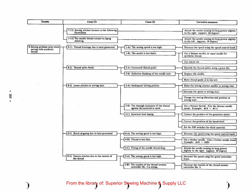
Trouble Cause (1) Cause (2) Corrective measures
8. Sewing problem arise whensewing with syntheticthread.
7-12) Sewing stitches become as the followingillustration.
7-13) The needle thread cros.ses in zigzagstitching.
8-1) Thread breakage due to heat generated
8-2) Thread splits finely.
8-3) Loose stitches at sewing start
8-4) Stitch skipping due to heat generated
8-5) Uneven stitches due to the stretch ofthe thread
)
1-A) The sewingspeed is too high.
1-B) The needle is too thick.
2-A) Unsmooth thread paths
2-B) Defective finishing of the needle hole
3-A) Inadequate sewing process
3-B) The through resistance of the tlucadagainst the material is small.
3-C) Incorrect feed timing
4-A) The sewing speed is too higli.
4-B) Thread is too thin.
4-C) Tilting of the needle thread loop
S-A) The sewing speed is too high.
S-B) The tension of the thread tensioncontroller No. 2 is strong.
) )
Attach the needle turning its long groove slightlyto the right, (approx. 20 degree)
Attach the needle turning its long groove slightlyto the left, (approx. 10 degree)
Decrease the speed using the speed control knob.
Use a thinner needle, or super needle forsynthetic thread.
Use silicon oil.
Smooth the thread paths, using a green file.
Replace the needle.
Move thread guide A to the left.
Make the sewingstitches smaller at .sewing start.
Decrease the speed at sewing start.
Change the sewingdirection and position atsewing start.
Use a thinner thread. (Use the thinner needlecount. Lxainple: #14 -» #11)
Correct the position of the generator stator.
Correct the position of the handwhecl.
.Set the DIP switches for thick material.
Dccrca.se the speed using the speed control knob.
Use a thicker needle. (Use a thicker needle countHxample: #18 -* #20)
Attach the needle turning its longgrooveslightly to the right, (approx. 20 degree)
Decrease the speed usingthe .speed controllerknob.
Decrease the tension of the thread tensioncontroller No. 2.
)From the library of: Superior Sewing Machine & Supply LLC
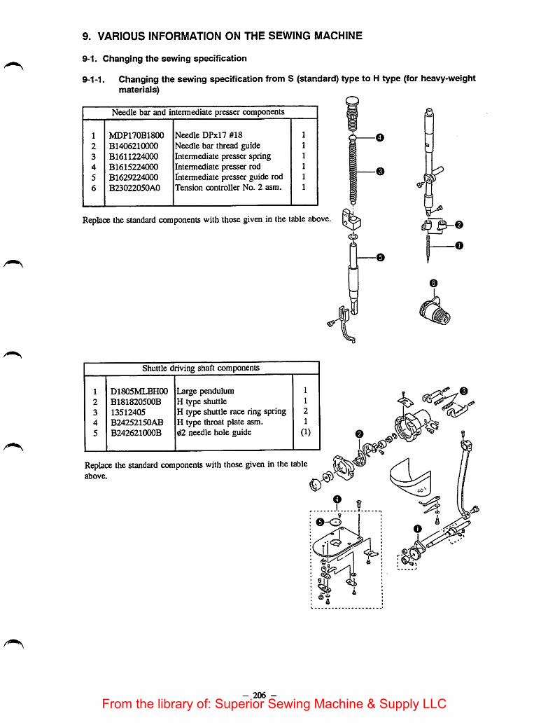
9. VARIOUS INFORMATION ON THE SEWING MACHINE
9-1. Changing the sewing specification
9-1-1. Changing the sewing specification from S (standard) type to H type (for heavy-weightmaterials)
Needle bar and intermediate presser components
1 MDP170B1800 Needle DPxl7 #18 1
2 B1406210000 Needle bar thread guide 1
3 B1611224000 Intermediate presser spring 1
4 B1615224000 Intermediate presser rod 1
5 B1629224000 Intermediate presser guide rod 1
6 B23022050A0 Tension controller No. 2 asm. 1
Replace the standard components with those given in the table above. l1|
Shuttle driving shaft components
1 D1805MLBH00 Large pendulum 1
2 B181820500B H type shuttle 1
3 13512405 H type shuttle race ring spring 2
4 B24252150AB H type throat plate asm. 1
5 B242621000B d2 needle hole guide (1)
Replace the standard components with those given in the tableabove.
- 206 -
From the library of: Superior Sewing Machine & Supply LLC

9-1-2. Changing the sewing specificationfrom S (standard) type to G type (for heavy-weightmateriais)
Machine head and miscellaneous cover components
1 B1132521000 Needle thread presser spring 1
2 B1145210000 Needle thread presser mounting base 1
3 10129104 Needle thread presser plate 1
4 SD0380551SL Hinge screw 1
5 SS7090910SP Screw 1
6 SS7110840SP Screw
7 TA0750704R0 Plug 1
8 TA1470704R0 Plug 1
9 B3118771000 Thread guide of tension controller No.2 1
10 B23022050A0 Tension controller No.2 joint 1
Add the components shown in the table above.
Main shaft and needle bar components
1 MDP170B2300 Needle, DPxl7 #23 1
2 B2312210A00 Tension release notch 1
3 B19012100A0 Link thread take-up asm. (1)4 B1401210A00 Needle bar 1
5 B1206210A00 Counterweight 1
6 B19012100B0 Link thread take-up asm. 1
7 B14072100CO Needle bar crank (1)8 B1903210000 Thread take-up crank (1)9 B1406210000 Needle bar thread guide 1
Replace the standard components with those shown in the tableabove.
In addition to the replacement of the aforementioned components,the thread trimming cam timing should be changed appropriately.(See page 43.)
- 207 -
Oo^
h
From the library of: Superior Sewing Machine & Supply LLC
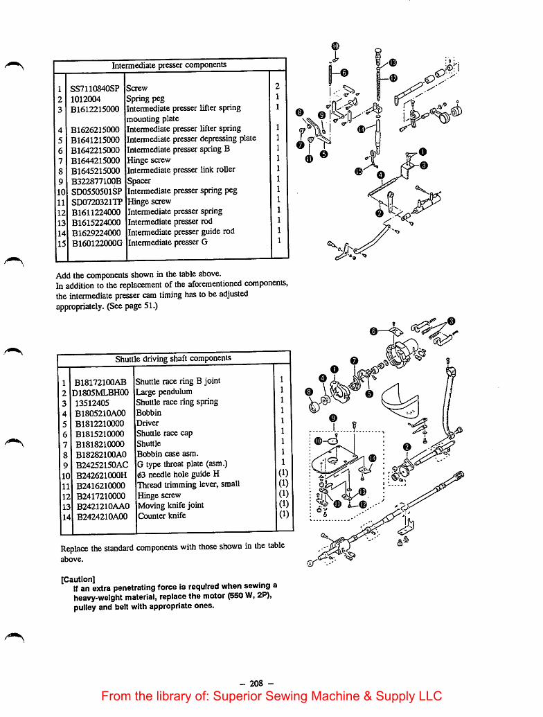
Intermediate presser components
1 SS7110840SP Screw 2
2 1012004 Spring peg 1
3 B1612215000 Intermediate presser lifter spring 1
mounting plate4 B1626215000 Intermediatepresser lifter spring 1
5 B1641215000 Intermediate presser depressing plate 1
6 B1642215000 Intermediate presserspring B 1
7 B1644215000 Hinge screw 1
8 B1645215000 Intermediate presser link roller 1
9 B322877100B Spacer 1
10 SD0550501SP Intermediate presser spring peg 1
11 SD0720321TP Hinge screw 1
12 B1611224000 Intermediate presser spring 1
13 B1615224000 Intermediate presser rod 1
14 B1629224000 Intermediate presser guide rod 1
15 B160122000G Intermediate presser G 1
Add the components shown in the table above.In addition to the replacement of the aforementioned components,the intermediate presser cam timing has tobeadjustedappropriately. (See page51.)
Shuttle driving shaft components
1 B18172100AB Shuttle race ring B joint 1
2 D1805MLBH00 Large pendulum 1
3 13512405 Shuttle race ring spring 1
4 B1805210A00 Bobbin 1
5 B1812210000 Driver 1
6 B1815210000 Shuttle race cap 1
7 B1818210000 Shuttle 1
8 B18282100A0 Bobbin case asm. 1
9 B24252150AC G type throat plate (asm.) 1
(1)10 B242621000H 03 needle hole guide H11 B2416210000 Thread trimming lever, small (1)
12 B2417210000 Hinge saew (1)
13 B2421210AA0 Moving knife joint (1)
14 B2424210A00 Counter knife (1)
Replace the standard components with those shown in the tableabove.
[Caution]If an extra penetrating force is required when sewing aheavy-weight material, replace the motor (550 W, 2P),pulleyand belt with appropriate ones.
- 208 -
I aa-A
o—^
(D
|J!\
From the library of: Superior Sewing Machine & Supply LLC

9-1-3. AMS-215C subclass model modification unit
Part No. Description of modification
B26062150A0
B43012150B0
B4301215AB0
B4301215BB0
Standard -* Separately-driven feeding frameStandard Inverting intermediate presserDouble-stepped stroke feeding frame -» Inverting intermediate presserSeparately-driven feeding frame Inverting intermediate presser
9-2. Options
Name of part
1. Intermediate presser foot
Type
Intennediate presser foot (A)
Intermediate presser foot (B)
Intennediate presserfoot (E)
Intermediate presserfoot (F)
Intermediate presser foot (G)
Intermediate presser foot (Q
Intermediate presser foot (D)
Intermediate presser foot asm.with ring
- 209 -
Part No.
BI601220000
B160I22000B
B160122000E
B160122000F
B160122000G
B160122000C
B160122000D
B16012200A0
Size (mm)
0Ax0BxCxL
2.2 x3. 6 x6 x29. 5
0Ax0BxCxL
3.5 X 5. 5 X 6 X 29. 5
0Ax0BxfixL
1.6 X 2. 6 X 6 X 29. 5
0Ax0BxCxL
2.2 x3. 6 x9 x29. 5
0Ax0BxCxL
2. 7 X 4.1 X 5 X 29. 5
0Ax 0Bx 0Cx C xL
2.2X3.6X 12x6x29.5
0 A X 0 B X L
2.2 xl2 X34.5
0Ax0Bx2xL
2.2 X 10 X 6 X 29. 5
From the library of: Superior Sewing Machine & Supply LLC
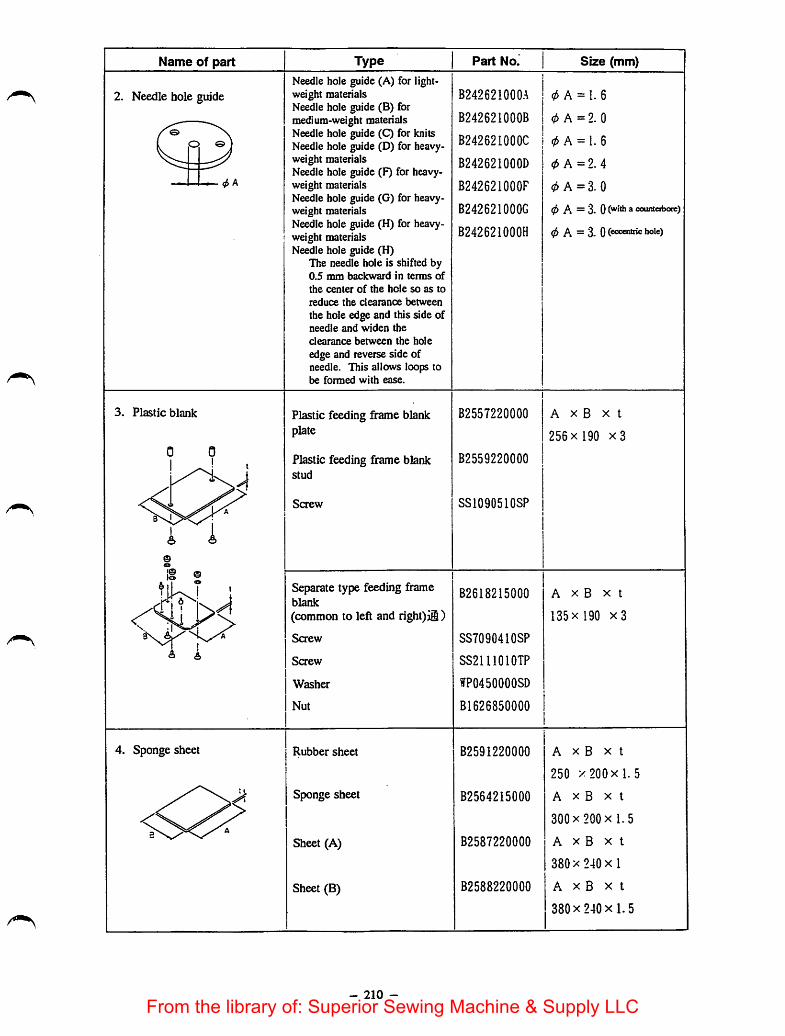
Name of part
2. Needle hole guide
3. Plastic blank
4. Sponge sheet
TypeNeedle hole guide (A) for lightweight materialsNeedle hole guide (B) formedium-weight materialsNeedle hole guide (C) for knitsNeedle hole guide (D) for heavyweight materialsNeedle hole guide (F) for heavyweight materialsNeedle hole guide (G) for heavyweight materialsNeedlehole guide (H) for heavyweight materialsNeedle hole guide (H)
The needle hole is shifted by0.5 mm backward in terms of
the center of the hole so as to
reduce the cleaixince between
the hole edge and this ade ofneedle and widen the
clearance between the hole
edge and reverse side ofneedle. This allows loops tobe formed with ease.
Plastic feeding frame blankplate
Plastic feeding frame blankstud
Screw
Separate type feeding frameblank
(common to left and right) jl)
Screw
Screw
Washer
Nut
Rubber sheet
Sponge sheet
Sheet (A)
Sheet (B)
- 210 -
Part No. Size (mm)
B242621000A 0 A = 1.
B242621000B 0 A = 2.
B242621000C 0 A = 1.
B242621000D 0 A = 2.
B242621000F 0 A = 3.
B242621000G 0 A = 3.
B242621000H 0 A = 3-
B2557220000
B2559220000
SS1090510SP
B26182150G0
SS7090410SP
SS2I11010TP
WP0450000SD
B1626850000
B2591220000
B2564215000
B2587220000
B2588220000
A X B X t
256x 190 x3
A X B x t
135X 190 x3
A X B X t
250 X 200x 1. 5
A X B X t
300 X 200 X 1.5
A X B X t
380 X 240 X 1
A X B X t
380x 240x 1.5
From the library of: Superior Sewing Machine & Supply LLC

Name of part
5. Feed plate blank
6. Machinable invertingintermediate presser plate
Part No. Size (mm)
Feed plate blank with knurl B2556215C00 2 i x fis X t
285 X 199 XI. 2
Feed plate blank without knurl B2556215B00 C i x fij x t
285 X 199 XI. 2
Feed plate blank without knurl B2556215D00 2i x H? x t
285 X 199 xO. 5
Feeding frame blank, rightwith knurl
B2622215000 A x B x t
193x 135x4
i Double-stepped feeding frame B2626215000 A xB X tblank without knurl (common 193 x 135 X4to left and right)
Feeding frame, left with knurl B2623215000 A xB x t
193x 135x4
Separate type feeding frameblank with knurl
Separate type feeding frameblank without knurl
- 211 -
B2620215000 A x B x t
193x 279x4
B2621215000 A x B x t
193x 279x4
From the library of: Superior Sewing Machine & Supply LLC
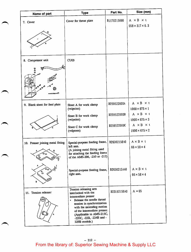
Name of part
7. Cover
8. Compressor unit
9. Blank sheet for feed plate
10. Presser joining metal fitting
11. Tension releaser
Part No.Type
Cover for throat plate B1170215000
CU03
Sheet A for work clamp(velpolen)
Sheet B for work clamp(velpolen)
Sheet C for work clamp(velpoien)
B259522000A
B259522000B
B259522000C
Special-purpose feeding frame,left asm.
(A joining metal fitting usedfor attaching the feeding frameof the AMS-206, -210 or -212)
jSpecial-purpose feeding frame,right asm.
Tension releasing arminterlocked with theintermediate presser• Release the needle thread
tension in synchronizationwith the ascending motionof the intermediate presser.(Applicable to AMS-215C,-220C, -22B, -224B and -229B models.)
- 212 -
B26302150A0
B2630215AA0
B23152150A0
Size (mm)
A X B X t
558x 317x 0.3
A X B X t
1000 X 675 X 1
A X B X t
1000x 675x3
A X B X t
1000x 675x2
A X B X t
66x58x4
A X B X t
66x58x4
A=65
From the library of: Superior Sewing Machine & Supply LLC

Name of part Part No. Configuration
12. Needle thread clamping device B21202150A0
13. One-touch utility clamp asm. B26402150B0
14. Cassette holder asm.
15. Needle cooler asm.
In addition to the part with the aforementioned part No., twomore parts are required as shown below.
Sliderasm. (2)B26412150A0
SS6150610SP
Slider attaching screw (4)
B25822150A0
B47202150B0
In addition to the partwith theaforementioned part No., twomore parts are required as shown below.
- 213 -
B2581210A0
Cassette holder
fixing plate asm.
From the library of: Superior Sewing Machine & Supply LLC

16. Milling unit MU-07
U r < •
17. Shuttle race cap for preventing stitch skipping (2-plied)
18.
B181598000C
B1815210A00
Shuttle race ring joint (for G type)Shutae race ring joints for preventing stitch skipping has been newly prepared. It comes in two types, interms ofdimension A, i.e., 0.8 mm and 1.3 mm. For the Gtype model ofsewing machine, standarddimension Aofthe shuttle race ring joint isset to 1.3 mm. Reducing the clearance provided between theneedle and the needle guard enables the machine to form loops more easily, thereby preventing stitch
Height of theneedle guard
Part No.Needle
count
A = 0.8mm B18172100AC Up to #14
A = 1.3mm B18172100AB (standard) Up to #24
A = 1.9mm B18172100AO Up to #25
•VI
19. Feeding frame arm B25522150A0
11
- 214 -
From the library of: Superior Sewing Machine & Supply LLC

1
NJ
9-3. BLOCK diagram
SCALESEWINQ MACHINETHREAD THROUGHSREED4/R
eOHDIN-WINDER
START SW
PRESSURE
SW
POWER
SOURCE
MARKING
LIGHT
7P I I 7P I I eR|
—' '̂=*1 —fSFIJ5S JS3
(PMDC)
l/F FOB
PI 4 P24 TJ24
J16 Pis
T-sJ"
SR IPS9
JS7
POWER PCS
)
JS4(PMOCl
I eR I P56
(PGM-6A) I I J90I I
)
12P
n\ P30
J79 P7fl
a
M8603S2tOAOPMDC
P62 J 62
)
o- AVS
P76 J7e
BLUE PI*
white p>k
SYNCHRONIZERSTOP SW^4X OWO*
4Phfl4PhTH.BRsensor
@ Timor sol
^Wipof sol
Wipor SW
X-PM
(Li jre
WHITE
MOTOR
CLUTCHBRAKE
MACHINE
«|(PGM^A) 472 o. POWERwill gouHCE
(PK47)
)From the library of: Superior Sewing Machine & Supply LLC

I
ls>I—»
as
I
) )
9-4. SOLENOID circuit diagram
P 3 2 J 7 7 P 7 7
1WH 1 T E
1
2
+ 3 3 V
WP B (N)BLACK
2
3RED
4
5
6
+ 3 3 V 4GREEN
T RM(N) bORE E N/YE L LOW
61
P 3 0
+ 3 3 V
WH I TE
B R K(N)GREEN
RED
CL(N)BLACK
)
BLACK
GRAY
WH I TE
WH I T E
GREEN/YELLOW
) )
P7 3 J 7 3
WH I TE
WH I TE 3 WP SOL. 8.7Q
COM
BLACKN.C
WP SW
3 TRM SOL. 8.70
P 7 1 J 7 1
M BRAKE 3.30
CLUTCH 12.20
From the library of: Superior Sewing Machine & Supply LLC
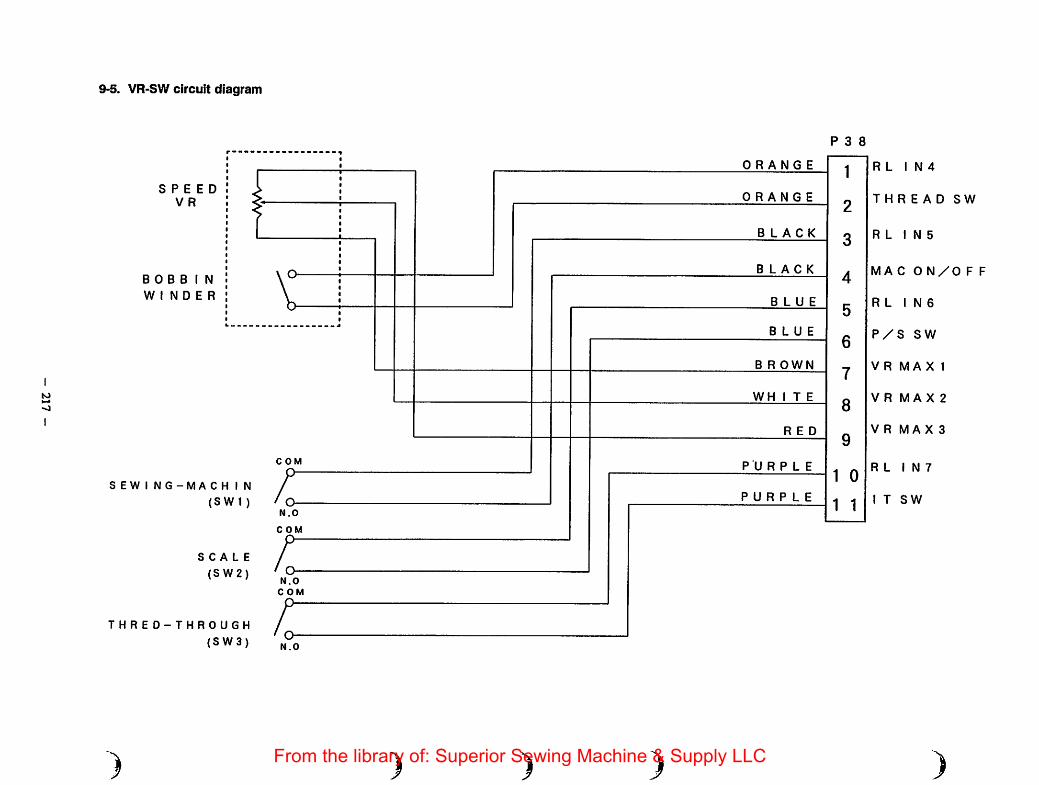
lO
9-5. VR-SW circuit diagram
SPEEDV R
BOBBIN
W I N D E R
S EW I N 6-MA C H I N
(SW 1 )
SCALE
(S W2)
THRED-THROUGH
{SW3)
)
COM
LN.O
COM
LN.O
COM
LN.O
)
ORANGE
ORANGE
BLACK
BLACK
BLUE
BLUE
B R OWN
WHITE
RED
PURPLE
PURPLE
) )
P 3 8
1
2
3
4
5
6
7
8
9
1 0
1 1
R L I N 4
THREAD SW
R L I N 5
MAC ON/OFF
R L I N 6
P/S SW
V R MA X 1
V R MA X 2
V R MA X 3
R L I N 7
I T SW
)From the library of: Superior Sewing Machine & Supply LLC

to
00
1
9-6. SENSOR circuit diagram
P 3 5
+ 5 V 1XORIG(N)
3
G N D 5+ 5 V 7
XLMTP(N)9
G N D 11+ 5 V 13
YLMT 15G N D 17
19
21
STOP SW 23
25
+ 5 V 2
YORiG 4
G N D 6
+ 5 V 8
XLMTM(N) 10
G N D 12
14
16
18
20BREAK(N) 22
STRB4 24
26
)
P 7 6
1
3
5
7
9
11
13
15
17
19
21
23
25
2
4
6
8
10
12
14
16
18
20
22
24
26
)
J 7 6
1
3
5
7
9
11
13
15
17
19
21
23
25
2
4
6
8
10
12
14
16
18
20
22
24
26
RED
WHITE
B LACK
RED
WH I T E
B LACK
RED
WHITE
BLACK
B LACK
RED
WH I T E
BLACK
RED
WHITE
B LACK
BLACK
BLACK
) )
P 8 0
3 + 5 V
2 XORIG{N)
1 G N D
P 8 1
3 + 5 V
2XLMTP(N)
1G N D
P 8 4
3 + 5 V
2 YLMT
1 G N D
P 8 3
3 + 5 V
2 YORiG
1 G N D
P 8 2
3 + 5 V
2 XLMTM(N)1 G N D
P 8 6
1 STOP SW
2 STRB4
TH BREAK(N)
From the library of: Superior Sewing Machine & Supply LLC

I
to1-^
VO
I
9-7. AIR VALVE circuit diagram
+24VA
AIR OPRER(N)
+24VA
AIR OPREL(N)
+24VA
AIR IPRE{N)
+24VA
AIR INVS(N)
+24VA
AIR WP(N)
+24VA
AIR TCLMP(N)
+24VA
AIR STROKE(N)
+24VA
AIRTR 3(N)
)
+ 24VA
AIR SW
GND
P34
1
2
3
4
5
6
7
8
9
10
11
12
13
14
15
16
17
18
19
20
21
22
23
24
25
26
27
28
29
30
31
33
32
34
)
J79
1
2
3
4
5
6
7
8
9
10
11
12
13
14
15
16
17
18
19
20
21
22
23
24
25
26
27
28
29
30
31
33
32
34
P79
1
2
3
4
5
6
7
8
9
10
11
12
13
14
15
16
17
18
19
20
21
22
23
24
25
26
27
28
29
30
31
33
32
34
RED
BLACk
RED
BLACK
RED
WHITE
BLACK
) )
P91
+24VA
AIR OPRER(N)
P92
P78
+24VA
AIR IPRE(N)
+24VA
AIR SW
GND
J78 1 >
BLACK;
From the library of: Superior Sewing Machine & Supply LLC

tolOo
)
9-8. PEDAL SW circuit diagram
P2 1
START SWBLACK
STRB 4(N)BROWN
PRES1SWRED
ORANGE
STRB 4(N)
) ) ) )
J 8 8 P8 8
RED
GREEN START SW
WHITE
BLACK PRESSUER SW
From the library of: Superior Sewing Machine & Supply LLC
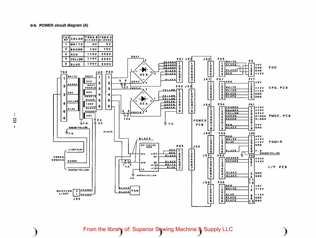
to
9-9. POWER circuit diagram (A)
)
TB2NO COLOR
TRNS B0-130V
TRNS A0-2 60V
1 WH 1 TE OV 0 V
2 BROWN 1 OV 1 OV
3 RED 1 1 OV 200 V
4 YELLOW 1 1 5V 230V
6 BLUE 1 3 0 V 250 V
TB2 J 40
GRAY1
2I2.V
GRAY
PURPLE 3
4PURPLE
BLACK 5
11OOV6
BLACK
ORANGE
|46V 1I. 2 A
GREEN/YELLOW
1T F.G.
LIGHT BLUE
POWER
SOURCE
GREEN/YELLOW
MARK I NG
LIGHT
J 8 5
P40
GRAY
orange
orange
orange
B LACKB.IACK
GRAYblack
P 6 3 J 8 37AT pubple
yg LLOW
vellow
yellow
RREgN
green
ELBE.EN
1 OA
BLACK
BLACKFAN
)
RED
+ S V
G1
G2
+ 12V-12V
1 REDBLACK
BLACK
WH 1 TE
BLUE
)
J 6 9
J 64
POWE R
FOB
J 6 6
J 6 5
pegP2
BLACK + S V
BLACK GND
RED + 1 2 V
P 5 7 PI 7
1234
56
RED1234g
+ 6 V
WH 1 TE + 1 2 VB L 1 UE -12 V
BLACK GNDBLACK
8 GND
ORANGE
orange
vellow
GREEN
GREEN
REP
PS 6
REP
WH I TE
BLUE
pel
123456
78
+ 70V
+ 70V
+ 24 V
O-GND
0-GND
+ B V
GNO
J90+ 6 V
+ 1 2 V
-12 V
GNO
FDD
CPU. PCS
PMDC.PCS
PGM-B
1 12 23 34 46 66 6
J 62 1 PS2
1 12 23 34 45 56 67 7
black
rdF. G
GREEN/YELLOW
J 6 8 P58
BLACK
BLACK
)
56
7
3
41 1
1 2
2
89
1 0
+ 3 3 V
+ 3 3 V
GND
GND
+ 5 V
+ 1 2V
-12 V
GND
GND
l/F RGB
)From the library of: Superior Sewing Machine & Supply LLC
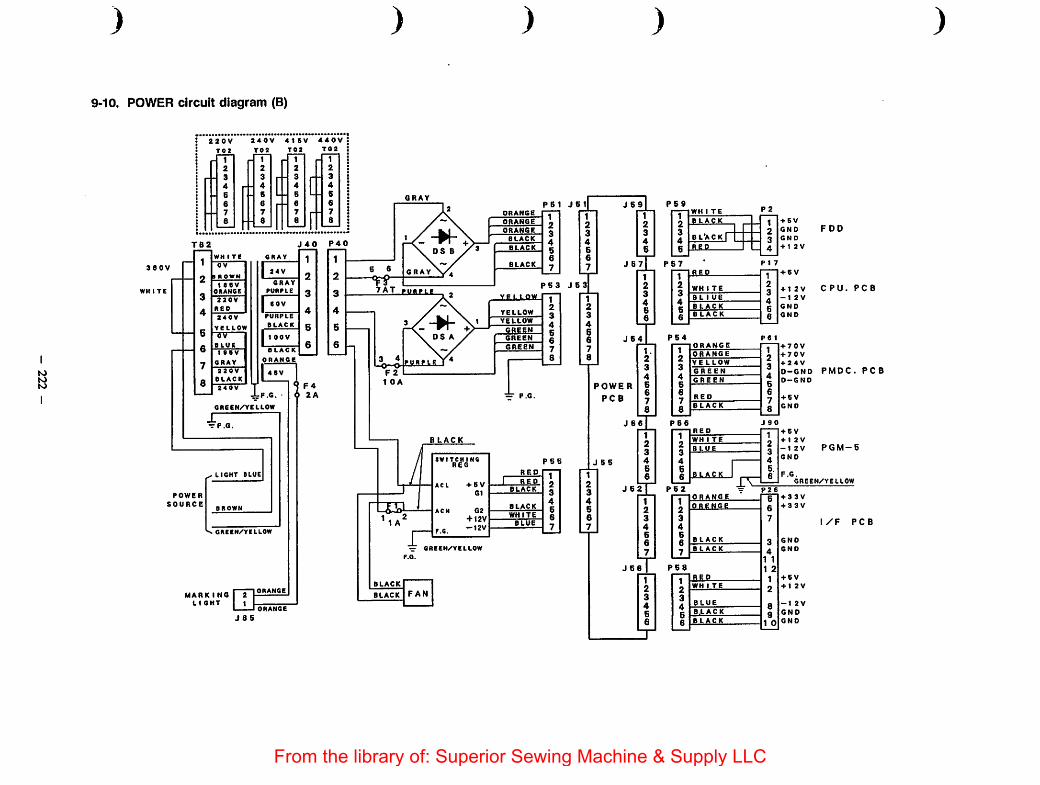
to(Oto
)
9-10. POWER circuit diagram (B)
3 eov
WH I TE
220 V 240V 4 1 6V 440V
Toa Toa Toa T02
_ 1 - 1 1 1
2 2 2 2
3 3 r 3 r 3
4 4 r 4 r 4. 6 6 L 6 L 6
6 6 6 6
7 7 7 7
8 8 8 r 8
TB2
0 V
inowN
t «BV0IIAH6E
aaov
neo
240V
YELLOW
TT
BLUE
1 • 0 V
ORAV
a 30V
BLACK
•^F.6.
J 40
GRAY 1
1 24V2
GRAYPURPLE q
1BOV4
PURPLE
BLACK 5
1100V6
BLACK
IQREEN/'VELLOW
9 F42A
LIGHT BLUE
POWER
SOURCE
GREEN/'YCLLOW
MARK i NOL I QHT
2 -
1 -
J8S
)
7AT fubple
BLACK
BLACK
SW TCHING
+ B V
+ I2V-12V
— GREEN/'YELLOW
F.G.
BLACK FAN
)
FBI J61ORANGE
ORANGE
ORANGE
BLACK
BLACK
J S 3
YELIQW
YELLOW
YELLOW
GREENGREEN
GREEN
RED
RED
BLACK
BLUE
)
J S9
J 67
J 64
POWER
PCB
J 5 5
J 66
J 62T1234667
J 68
P&9
P67
WH 1 TE P 2
BLACK t + GV
2 GNO
BL'ACK r 3 GNO
RfiP _ 4 + 1 2 V
123466
RED1234
+ BV
WH 1 TE + 1 2V
B L 1 UE -12 V
BLACK GNO
BLACK 6 GNO
P64
FDD
CPU. PCB
+ 70V
+ 70V
4-24V
0-GND PMDC. PCBO-GND
+ B V
GNO
123
ORANGE12345678
ORANGE
V E L LOW
GREEN45678
GREEN
RED
BLACK
P62
1234667_
P68
123456
BLACK
SX2
ORgNGE
+ BV
+ 1 2 V
-1 2V
GNO
PGM-5
F.G.GREEN/YELLOW
+ 33 V
+ 33 V
GNO
GNO
+ 6V
+ I 2V
-1 2V
GNO
GNO
1/F PCB
)
From the library of: Superior Sewing Machine & Supply LLC
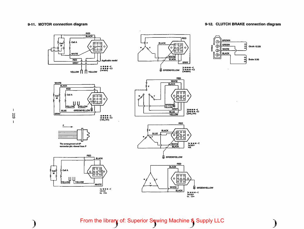
S>S)U)
9-11. MOTOR connection diagram
BUCK
O O O
O O O
WHITE
REP
GRAY
YELLOW n n YELLOWUW *»»-C2(ICIOOV)
)
BUCK
Co A
YELLOW
BLUE GREEN/YELLOW (S
GRAY
[)Tho anraneetnont of SPconnoctor pin: viowod from P
ConA
YELLOW
O O O
O O O
lOVCC-E10CSV-E2(im/XH)
O O O
o ono
WHTE
lU « «•»lOIISV
Ul. CSA
)
RED
BUCKo q_pRO_pcoo
BUCK
GRAY
® GREEN/YELLOW » » • « -e2(S«200V)
WHITE
BUCK
YELLOWGRAY
O O O
O O O
YELLOW
BUCKO O O
RDJ3o o o
BUCK
® GREEN/YELLOW
RED
BUCK
O O O
Q O QO O O
30*90»«»(30X1./KH)
3V » «)» -E3*3aov
9-12. CLUTCH BRAKE connection diagram
0Q>
<2>Qy
|£
BROWN
GREEN
WHITE
WHITE ® GREEN/YELLOWBUCK
3U » « * -C3»220VUl. CSA
3From the library of: Superior Sewing Machine & Supply LLC

N)
9-13. SYNCHRONIZER circuit diagram
+5V
U DET
D DET
GND
TGIN
TGIN
GND
I i
I I
\ I
\J
) )
-<§H
lOOQ
R2 3
)
1
7\ WHITE-j—j—Iqi I—©"jVVXC DN-6839^6 -1-C1
—(§>-BROWN
YELLOW 3300/50ORANGE
I I RED
\J 1—(§>^
HIC1
100QR3 3
n/V\Q DN-6839
2300/50
TGIN
Tacho
Generator
)
HIC2
From the library of: Superior Sewing Machine & Supply LLC

Computer-controlled cycle Machine with a Double-stepped StrokeFeeding frameAMS-215CSB
AMS-215CHB
AMS-215CGB
[Note]This Engineer's manual covers only the part which is the feature making this machine different from theAMS>215C.
1. FEATURES
1) Lowering the feeding frame in the double-stepped actions allows the operator to position the sewing product onthe machine with accuracy.
2) The height of the feeding frame in its intermediatestop position can be adjusted within the range of 0 through30 mm with ease according to the thickness of the sewing product to be sewn.
3) The exclusive pedal switch (PK47) allows the operator to select the pedal operation mode as desired.
2. SPECIFICATIONS AND SPECIFIED VALUE
1) Height of the feeding frame in its intermediate stop position: 0 to 30 mm.
3. OPERATION OF THE SEWING MACHINE
3-1. Configuration
O
O Feeding frameIt comes down by operating the pedal switch
225 -
Pedal swfltch
(GPK470010AB)
O Feedingframe
Height adjusting knob
O Feeding frame and intermediate positionstop svntch (Double-stepped feeding frame switch)
0 Steirtsvntch*0 is notused inthe normal operation
of the machine.
From the library of: Superior Sewing Machine & Supply LLC
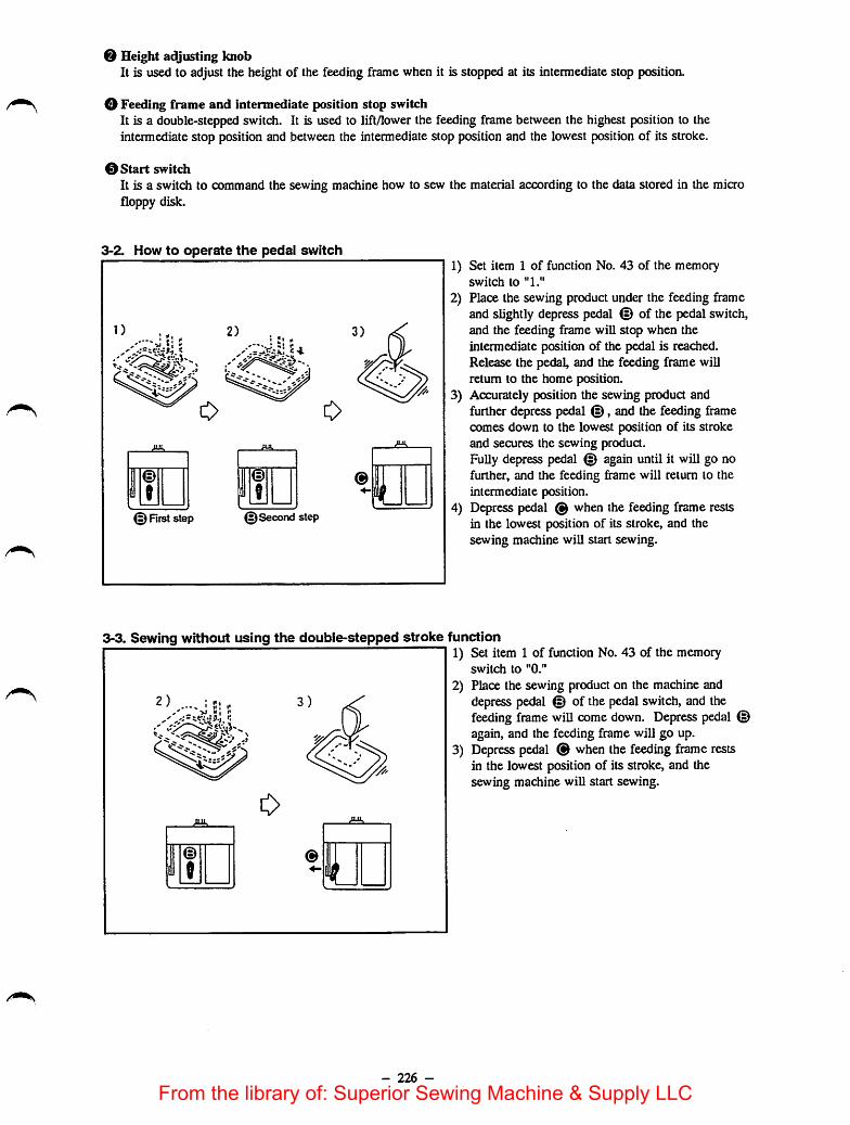
O Height adjusting knobIt is used to adjust the height of the feeding frame when it is stopped at its intermediate stop position.
O Feeding frame and intermediate position stop switchIt is a double-stepped switch. It is used to lift/lower the feeding frame between the highest position to theintermediate stop position and between the intermediate stop position and the lowest position of its stroke.
0 Start switchIt is a switch to command the sewing machine how to sew the material according to the data stored in the microfloppy disk.
3-2. How to operate the pedal switch
0
.ua.
1?@
11 L@ Rrststep (^Second step
3-3. Sewing without using the double-stepped stroke
- 226 -
1) Set item 1 of function No. 43 of the memoryswitch to "1."
2) Place the sewing product under the feeding frameand slightly depress pedal © of the piedal switch,and the feeding frame will stop when theintermediate position of the pedal is reached.Release the pedal, and the feeding frame willreturn to the home position.
3) Accurately position the sewing product andfurther depress pedal @, and the feeding framecomes down to the lowest position of its strokeand secures the sewing product.Fully depress pedal © again until it will go nofurther, and the feeding frame will return to theintermediate position.
4) Depress pedal © when the feeding frame restsin the lowest position of its stroke, and thesewing machine will start sewing.
function
1) Set item 1 of function No. 43 of the memoryswitch to "0."
2) Place the sewing product on the machine anddepress pedal © of the pedal switch, and thefeeding frame will comedown. Depress pedal ©again, and the feeding frame will go up.
3) Depress pedal ® when the feeding frame restsin the lowest position of its stroke, and thesewing machine will start sewing.
From the library of: Superior Sewing Machine & Supply LLC

4. ADJUSTMENTS4-1. Adjusting the mechanical components
STANDARD ADJUSTMENTS
(1) Adjusting the initial position of the intermediate stop cylinder1) Adjust the center-to-center distance between the double-stepped stroke fulcrum shaft and the intermediate
cylinder knuckle connecting shaft to 112.5 ± 0.3 mm when the intermediate stop cylinder drawsin the most,
Double-stepped stroke cylinder
Double-stepped stroke fulcrum shaft
Nut
5§E
t
V0 0 Knuckle
112.5±0.3 (Atthe time of the max. stroke)
Fig. 4-1-1
Cylinder rod
Feed bracket
(2) Adjusting the intermediate stop position of the feeding frameAdjust the height ofthe intermediate stop position ofthe feeding frame to allow the operator to position thesewing product on the machine with ease.Adjust the clearance between the feeding frame and the sewing product on the machine to approximately 1mm. (The intermediate stop position ofthe feeding frame can be adjusted within the range of0 through 30mm above the top surface of the throat plate.)
Fig. 4-2-1
- 227 -
From the library of: Superior Sewing Machine & Supply LLC

HOW TO ADJUST
1) Draw the knuckle in the direction of the arrow to allow thedouble-stepped stroke cylinder to reach the max. stroke.
2) Loosen the nut and turn knuckle until a 112.5±0.3 mmcenter-to-center distance is obtained between the fulcrum shaft
and the connecting shaft. Now, tighten the nut to fix theknuckle.
1) Loosen knob O.2) Turn knob O to adjust the intermediate stop position of the
feeding frame slightly higher than the material thickness. Turnknob O in direction A to heighten the intermediate stop positionof the feeding frame or in direction B to lower it.
3) Securely tighten knob O.
- 228 -
RESULTS OF IMPROPER
ADJUSTMENT
o If the center-to-center distance is shorter
than the specified value, the feedingframe will fail to go up as high as 30mm.
o If the intermediate stop position of thefeeding frame is too high, the materialmay not be positioned on the machinewith ease.
o If the intermediate stop position of thefeeding frame is too low, the materialcannot be smoothly moved on themachine.
From the library of: Superior Sewing Machine & Supply LLC

STANDARD ADJUSTMENTS
(3) Adjusting the pneumatic components1) Connect quick-coupling joint O in place and open air cock 0. Then pressure gauge O indicates 5 to 5.5
kgf/cm^ (0.5 MPa to 0.55 MPa). (Fig. 4-3-1)2) If pressure gauge O indicates 4 kgf/cm^ (0.4 MPa) or lower value, the machine will stop with Error 0
shown on the operation panel. (Fig. 4-3-1)3) Theair pressure on thefeeding frame cylinder retracting side has been reduced to 1 to 1.5 kgf/cm^ (0.1 MPa
to 0.15 MPa) and the feeding frame can be lowered by hand. (Fig. 4-3-2)4) The needle knob of the speed controller (for work clamp cylinder) has been fixed at the position that is
reached by loosening the knob by one turn after fully tightening it. (Fig. 4-3-3)5) The needleknob of the speed controller (intermediate presser cylinder(asm.)) is fixed using a nut with
loosened by 5 turns after it has been fully tightened. (Fig. 4-3-4)
@0 o
Fig. 4-3-1
1 to 1.5 kgf/cm= (0.1 to 0.15 MPa)
Air hose for double-stepped stroke cylinder
/Air hose for feedingframe cylinder, left
Air hose for feedingframe cylinder, right
Fig. 4-3-3
Fig. 4-3-2
- 229 -
READY
o11
1 1NumbCfi Input
Pattern No.
Mcd«l
X Scale 1i
Sue), lyp* 1SpM«
Y Scale
Preft
Counter
MOI
Solenoid valve (asm.)
Intermediate pressercylinder (asm.)
Fig. 4-3-4
From the library of: Superior Sewing Machine & Supply LLC

now TO ADJUST
1) Connea air supply hose to quick-coupling joint (female) O andfasten the hose with hose band 0.
2) Connect female side O 2nd male side O of the quick-couplingjoint.
3) Open air cock 0, pull upair regulating knob 0 and then adjustthe air pressure, by turning the knob, to allow pressure gauge Oto indicate an air pressure of 5 to 5.5 kgf/cm^ (0.5 MPa to 0.55MPa). Then, press the knob down to remain at that position.
4) If the air pressure is lower than the specified value, the machinewill stop while giving error 0 on the display.
* Close air cock 0 and press pushbutton 0, and the airpressure will be 0 kgf/cml
[Caution]After the adjustment, return the indication on pressure gaugeOto 5 to 5.5 kgf/cm' (0.5 MPa to 0.55 MPa). Now confirm thatError@ is not displayed any longer.
5) Set the machine in its sewing state. Now remove the air hose bypressing section 0 of pressure reducing valve O which isfixed on the solenoid valve (asm.), and connect a commerciallyavailable pressure gauge instead of the removed air hose. (Fig.4-3-2)Depress the feeding frame switch 5 times or more, and turnneedle knob 0 of pressure reducing valve O until theconnected pressure gauge indicates 1 to 5 kgf/cm' (0.1 MPa to0.5 MPa). Then fix the needle knob using nut 0 . Now,securely connect the removed air hose in place. (Fig. 4-3-2)
6) Referring to the Standard adjustment (3)-4), properly adjustneedle knob 0 of speed controller O 2nd fix the knob with nut0. (Fig. 4-3-3 and 4-3-4)
7) Remove the top cover.Referring to the Standard adjustment (3)-5), adjust needle knob0 of speed controller O properly. After the adjustment, fix itusing nut 0. (Fig. 4-3-5)
- 230 -
RESULTS OF IMPROPER
ADJUSTMENT
1) Function failure of the feeding framecomponents and intermediate pressercomponents may result.The machine stops with Error 0indicated on the operation box panel.
2) Even if the air pressure drops, it cannotbe detected. Under the normal operatingair pressure (5 to 5.5 kgf/cm* (0.5 MPato 0.55 MPa)), the sewing machine stopswith Error 0 indicated on the operationpanel.
3) An adequate work clamp pressingpressure is not provided.
4) The speed of vertical motion of thefeeding frame may be too high or toolow.
5) The intermediate presser may fail tomove smoothly, or it may generates akeen metallic noise when it is in
operation.[Caution]
Normally, Standard adjustment (3)-2)through -5) are not required to beadjusted. Needle knoiss and nutsreferred in steps 3) through 5), inparticular, have applied with oil-resistant white coating material toshow that they have been alreadyadjusted properly.
* To set the air pressure to 0 kgf/cm%close air cock 0 and press button 0.(See Fig. 4-3-1)
From the library of: Superior Sewing Machine & Supply LLC

STANDARD ADJUSTMENTS
(4) Connecting the pneumatic componentsThe schematic diagram for the pneumatic system is as follows:
Intermediate
stop cylinder
oo
Work cl£tmpfoot cylinder
©
OO
Intermediate
presser cylinder
©
00J06
oeJOS J04L J03L J04R
©J03R J02 JOl
© ©
o o2E
©
©
\A/
V
©
[AA
\
©
©,o o
0E
1
r 'V©
Air source 0
0
<
u - J
o V©
Fig. 4-4-1
OQuick-coupling joint socket © d6 air tube
Quick-coupling joint plug © d4 air tube
© Air cock o Barrel nipple
© RIter regulator 0 T-cheese
© Pressure reducing valve 0 Plug
© Speed controller (A) o Hose nipple
© Intermediate presser cylinder 0 Speed controller (8)
© Work clamp foot cylinder (right) 0 Y joint
© Work clamp foot cylinder (left) 0 Hose elbow
o Intermediate stop cylinder 0 Bbow union (B)
Solenoid valve (asm.)
© Manifold
Solenoid valve
- 231 -
\©
From the library of: Superior Sewing Machine & Supply LLC

now TO ADJUST
o Connect the pneumatic components properly referring to theschematic diagram.
- 232 -
RESULTS OF IMPROPERADJUSTMENT
o Malfunction of the feeding framecomponents and intermediate pressercomponents may occur, resulting inmachine failure or giving damages tothe related components.
From the library of: Superior Sewing Machine & Supply LLC

DISASSEMBLY/ASSEMBLY PROCEDURES
(5) Installing the pedal switch (PK47)1) Connect the connectors of the pedal switch to the conneaors located on the back of the control box
following the order as shown in the figure below.2) Connect a ground wire.
P K-47
Fig. 4-5-1
- 233 -
From the library of: Superior Sewing Machine & Supply LLC

CAUnONS IN DISASSEMBLY
o The connector of the pedal switch relay cable (asm.) is a lockingtype one. So, be careful not to draw it out forcibly.
- 234 -
CAUTIONS IN ASSEMBLY
o Be sure to connect the connector of the
pedal switch relay cable (asm.) followingthe correct order. If not, the feedingframe may fail to operate normally.
From the library of: Superior Sewing Machine & Supply LLC

DISASSEMBLY/ASSEMBLY PROCEDURES
(6) Assembling the double-stepped stroke feeding frame1) Assemble the double-stepped stroke feeding frame referring to Fig. 4-6-1.
Eiouble-steppedstroke cylinder
Hose
Speedcontroller
Double-stepped strokeheight adjustmentcomponents mounting plate
Thrust
Thrust
Double-stepped strokefulcrum shaft
Washer
Double-stepped strokemounting plate
Fig. 4-6-1
- 235 -
Double-steppedstroke heightadjustment plate
Washer
Cylinderretaining
""9 knuckle
Setscrew
Heightadjustmentknob
Flangebushing
Setscrew
Washer
Double-
steppedstroke lever
Double-steppedstroke lever
fulcrum shaft
Cylinderconncectingpin
From the library of: Superior Sewing Machine & Supply LLC

CAUTIONS IN DISASSEMBLY CAUTIONS IN ASSEMBLY
- 236 -
From the library of: Superior Sewing Machine & Supply LLC

DISASSEMBLY/ASSEMBLY PROCEDURES
(7) Assembling the double-stepped stroke push plate1) Assemble the double-stepped stroke feeding frame push plate to Fig. 4-7-1.2) Assemble the nutand the cylinder knuckle so that a 120.5 ± 0.3 mm center-to-center distance is provided
between the 05 mm hole in the work clamp foot cylinder and the 05 mm hole in the cylinder knuckle.(Fig. 4-7-2)
O
Setscrew
Work clamp footcylinder shaft
Work clampfoot cylinder
Double-steppedstroke push plate
Cylinder knuckle
Fig. 4-7-1
Work clampfoot lever B
Double-stepped
120. 5±0. 3mtn120. 5±0. 3mtn
Fig. 4-7-2
- 237 -
From the library of: Superior Sewing Machine & Supply LLC

CAUTIONS IN DISASSEMBLY CAUTIONS IN ASSEMBLY
- 238 -
From the library of: Superior Sewing Machine & Supply LLC

DISASSEMBLY/ASSEMBLY PROCEDURES
(8) Assembling the pneumatic componentsAssemble the pneumatic components according to Fig. 4-8-1.
J03L
J03R
Fig. 4-8-1
, Solenoid valve for
Needing frame
Solenoid valve for
intermediate presser
Solenoid valve for
double-stepped stroke
- 239
Solenoid valve
cord asm.
From the library of: Superior Sewing Machine & Supply LLC
CAUTIONS IN DISASSEMBLY CAUTIONS IN ASSEMBLY
- 240 -
From the library of: Superior Sewing Machine & Supply LLC
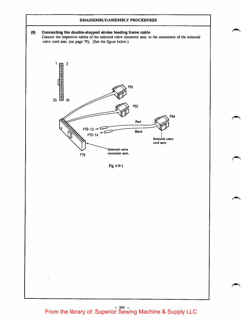
DISASSEMBLY/ASSEMBLY PROCEDURES
(9) Connecting the double-stepped stroke feeding frame cableConnect the respective cables of the solenoid valve connector asm. to the connectors of the solenoidvalve cord asm. (on page 79). (See the figure below.)
1 m 2
[i:
33 ea 34
0P79-13
P79-14
P79
Solenoid valve
connector asm.
Fig 4-9-1
- 241 -
Red
Black
P94
Solenoid valve
cord asm.
From the library of: Superior Sewing Machine & Supply LLC
CAUTIONS IN DISASSEMBLY CAUTIONS IN ASSEMBLY
- 242 -
From the library of: Superior Sewing Machine & Supply LLC
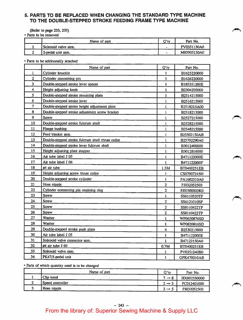
5. PARTS TO BE REPLACED WHEN CHANGING THE STANDARD TYPE MACHINETO THE DOUBLE-STEPPED STROKE FEEDING FRAME TYPE MACHINE
(Refer to page 233, 235)Parts to be removed
Name of part Q'ty Part No.
1 Solenoid valve asm. - PV0351130A0
2 2-pedal unit asm. - M85905130A0
Parts to be additionally attached
Name of part Q'ty Part No.
1 Cylinder knuckle 1 B1625220000
2 Cylinder connecting pin 1 B1626220000
3 Double-stepped stroke lever spacer 1 B185351200E
4 Height adjusting knob 1 B2304205000
5 Double-stepped stroke mounting plate 1 B2514215000
6 Double-stepped stroke lever 1 B2516215000
7 Double-stepped stroke height adjustment plate 1 B2518215A00
8 Double-stepped stroke adjustment screw bracket 1 B2518215000
9 Saew 1 B2527215000
10 Double-stepped stroke fulcrum shaft 1 B2528215000
11 Flange bushing 1 B2548215000
12 Feed blacket asm. 1 B25502150AB
13 Double-stepped stroke fulcrum shaft thrust collar 1 B25792290A0
14 Double-stepped stroke lever fulcrum shaft 1 B3012490000
15 Height adjusting plate stopper 1 B3012816000
16 Air tube label J 05 1 B471122000E
17 Air tube label J 06 1 B471122000F
18 64 air tube 1.5M BT0400251EB
19 Height adjusting screw thrust collar 1 CS0790731SH
20 Double-stepped stroke cylinder 1 PA1602510A0
21 Hose nipple 2 PJ032052503
22 Cylinder connecting pin retaining ring 2 RE0300000KO
23 Screw 1 SS6110520TP
24 Screw 2 SS6121010SP
25 Screw 2 SS8110422TP
26 Screw 2 SS8110422TP
27 Washer 1 WP0650876SD
28 Washer 1 WP0820816SD
29 Double-stepped stroke push plate 4 B2530215000
30 Air tube label J 05 1 B471122000E
31 Solenoid valve connector asm. 1 B47122150A0
32 64 air tube J 05 0.7M BT0400251EB
33 Solenoid valve asm. 1 PV0351240B0
34 PK47/3-pedal unit 1 GPK470010AB
Parts of which quantity used is to be changed
Name of part Q'ty Part No.
1 Clip band 7^8 HX002330000
2 Speed controller 2 — 3 PC012401000
3 Hose nipple 3 — 5 PJ032052503
- 243 -
From the library of: Superior Sewing Machine & Supply LLC
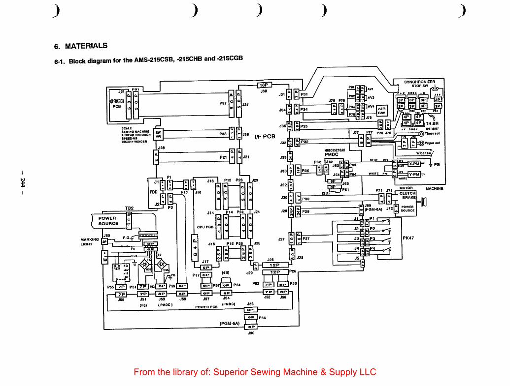
I
)
6. MATERIALS
6-1. Block diagram for the AMS-215CSB, -215CHB and -215CGB
SCALE
SEWIftq MACHINEthreap throuqhSPEEP.VRB08BIN.WIN0ER
P21 t J2I
P13 P23
)
l/F PCB
P14 P24
POWER
SOURCE
MARKING
LIGHT
OP
JS3
(PMDCI
PS9I ORl
CPU PCB
POWER PCB
J15 P16 P2S
0.
(PMDC)
(PGM-6A)
J35l«>
J33 5
)
J79 P79
Me603S2t0A0PMOC
P62 |J6Z
jsefljlf P36 ^[1
J29r;il.7 pzs
J27 |0||a|P2'
PI' P76 J76
BLUE P7«
WHITE P7S
P71 J71
»|(PQM-CA) J«ri s^wcE
SYNCHRONIZERSTOP SW
fX OKOX -X
4P
lGDnELhTH.BRsensor
(^Tlmot sol
Wiper 80)
X.PM
Y-PM
MOTOR
CLUTCH
BRAKE
PK47
MACHINE
)
From the library of: Superior Sewing Machine & Supply LLC

6-2. Air valve schematic diagram for the AMS-215CSB, -215CHB and -215CGB
+24VA
AtR OPRER(N)
+24VA
AIR OPREL(N)
+24VA
AIR IPRE(N)
+24VA
AIR INVS(N)
+24VA
AIR WP{N)+24VA
AIR TCLMP(N)
+24VA
AIR STROKE(N)
+24VA
AIRTR 3(N)
)
-f24VA
AIR SW
GND
P34
1
2
3
4
5
6
7
8
9
10
11
12
13
14
15
16
17
18
19
20
21
22
23
24
25
26
27
28
29
30
31
33
32
34
J79
1
2
3
4
5
6
7
8
9
10
11
12
13
14
15
16
17
18
19
20
21
22
23
24
25
26
27
28
29
30
31
33
32
34
P79
1
2
3
4
5
6
7
8
9
10
11
12
13
14
15
16
17
18
19
20
21
22
23
24
25
26
27
28
29
30
31
33
32
34
RED
BLACK
RED
BLACK
RED
BLACK
RED
WHITE
BLACK
)
P91
+24VA
AIR OPRER(N)
P92
P94
+24VA
AIR IPRE(N)
+24VA
AIR STROKE(N)
P78 J78
2 +24VA 2
1 AIRSW 1
4 GND 4
3 3
RED
WHITE
BLACK
)From the library of: Superior Sewing Machine & Supply LLC

) )
6-3. Pedal switch schematic diagram
START SW
STRB 4(N)
PRES 1 SW
STRB 4(N)
PR E S 2 SW
STRB 4{N)
P R E S 3 SW
STRB 3{N)
P RE S 4 SW
STRB 3(N)
P 2 7 J 4
1
2
BLACK2
1BLACK
J 1
3
4
BROWN2
1BROWN
J 5
5RED 2
6 RED
1
J 2
7
8
ORANGE 2
ORANGE1
J 3
9
1 0
BLUE 2
BLUE1
)
P4
P 1
P 2
P 3
) )
PK-47
r
START SW
7 PRESSUERE(R) SW
:7 STROKE SW
7 PRESSUERE(L) SW
J
From the library of: Superior Sewing Machine & Supply LLC

Computer-controlled Cycle Machine with a Double-stepped FeedingFrame
AMS-215CSL
AMS-215CHL
AMS-215CGL
[Note]This Engineer's manual covers only the part which is the feature making this machine different from theAMS-215C.
1. FEATURES
1) The machine comes with the feeding frame which is equipped with the degree of angle adjusting function so thatthe sewing product is uniformly clamped.
2) The machine is equip[)ed with a double-stepped feeding frame. In addition, the left- and right-hand side feedingframes can be simultaneously raised/lowered by changing over the setting of the DIP switch.
3) The lift of the left- and right-hand side feeding frames can be specified separately.
2. SPECIFICATIONS AND SPECIFIED VALUE
1) Lift of feeding frame (right)2) Lift of feeding frame (left)
Standard 25 mm Max. 30 mm
Standard 25 mm Max. 30 mm (Height of the feeding frame in itsintermediate stop position: 0 to 30 mm)
3. OPERATION OF THE SEWING MACHINE
3-1. Configuration
•JUKI Pedal switch
(GPK470010AB)
O Feeding frame
0 Height adjusting knob
0 Feeding frame switch and intermediate top switch(Double-stepped feeding frame switch)
0 Start switch
* 0 is not used in the normal operation of the machine.
- 247 -
From the library of: Superior Sewing Machine & Supply LLC
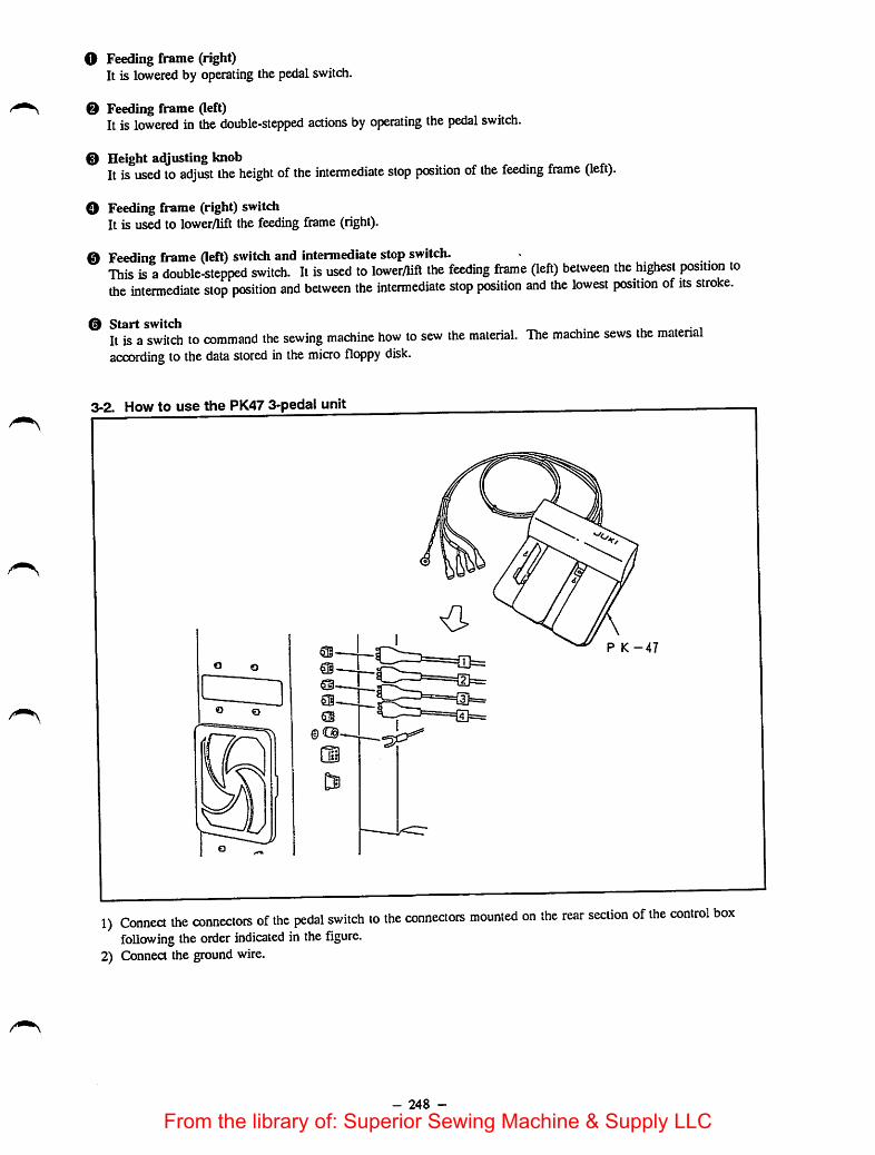
O Feeding frame (right)It is lowered by operating the pedalswitch.
0 Feeding frame (left)It is lowered in the double-stepped actions by operating the pedal switch.
0 Height adjusting knobIt is used to adjust the height of the intermediate stop position of the feeding frame (left).
O Feeding frame (right) switchIt is used to lower/lift the feeding frame (right).
0 Feeding frame (left) switch and intermediate stop switch.This is adouble-stepped switch. It is used to lower/Uft the feeding frame (left) between the highest position tothe intermediate stop position and between the intermediate stop position and the lowest position of its stroke.
0 Start switch u • iIt isa switch to command the sewing machine how to sew the material. The machine sews the materialaccording to the data stored in the micro floppy disk.
3-2. How to use the PK47 3-pedal unit
P K -47
o o
O o
1) Connect the connectors of the pedal switch to the connectors mounted on the rear section of the control boxfollowing the order indicated in thefigure.
2) Connect the ground wire.
- 248 -
From the library of: Superior Sewing Machine & Supply LLC

3-3. How to operate the pedal switch
OUl. AH,
©
f©
f©
9 i(§) First step (D Secondstep
1) Place the garment body under the feeding frame and depress pedal © ofthe pedal switch, and the feedingframe (right) will come down to secure the garment body.
2) Put the part to be sewn on the garment body under the feeding frame (left) and lightly depress pedal ©, and thefeeding frame (left) will stop in its intermediate stop position. Release the pedal in this state, and the feedingframe (left) wiU return to the previous height.
3) Position the part. Further depress pedal ©, and the feeding frame (left) wiU come down to the lowest positionofits stroke to secure the part. Fully depress pedal © again until itwill go no further, and the feeding frame(left) will return to its intermediate position.
4) Depress pedal © when both portions ofthe feeding frame rest in the lowest position ofits stroke, and thesewing machine will start sewing.
3-4. Sewing with the monolithic feeding frame installed on the machine
(D When the double-steppedstroke function is not used
1) Set item 1 of function No. 43 of the memory switch to"0."
2) Place the sewing product on the machine and depresspedal © ofthe pedal switch, and the feeding frame willcome down. Depress pedal © again, and the feedingframe will go up.
3) Depress pedal @ when the feeding frame rests in thelowest position of its stroke, and thesewing machinewill start sewing.
- 249 -
From the library of: Superior Sewing Machine & Supply LLC

When the double-stepped stroke function is used
s -i
0Jia. fUk
©1 f
©(
©
(§) Rrststep @ Secondstep
3-5. How to use a plastic blankIf you use a plastic blanksupplied with the machine, attach it to the feeding frame as illustrated in the figure.
Screw
1) Set item 1 of function No. 43 of the memoryswitch to "1."
2) Place the sewing product under the feeding frameand slightly depress pedal (§) of the pedal switch,and the feeding frame will stop when theintermediate position of the pedal is reached.Release the pedal, and the feeding frame willreturn to the home position.
3) Accurately position the sewing product andfurther depress pedal <s), and the feeding framecomes down to the lowest position of its strokeand secures the sewing product.Fully depress pedal (D again until it will go nofurther, and the feeding frame will return to theintermediate position.
4) Depress pedal @ when the feeding frame restsin the lowest position of its stroke, and thesewing machine will start sewing.
Washer
Feeding frame (left)
'Plastic blank
1) Machinea plastic blank supplied with the machine in accordance with the sewing patternshape.2) Attach the machined plastic blank to the feeding frame as illustrated in the figure shown above.(Caution)1. Plastic blank is common to the right and left portions of the feeding frame. So, machine a plastic blank
and attach it to the feeding frame, right.2. If necessary, adhere a sponge sheet or rubber sheet supplied with the plastic blank to the machined blank
for operation.
- 250 -
From the library of: Superior Sewing Machine & Supply LLC

4. ADJUSTMENTS4-1. Adjusting the mechanical components
STANDARD ADJUSTMENTS
(1) Adjustingthe degree of angle of the feeding frames (right) and (left)If thefeeding frames (right) and(left) are in parallel to thethroat plate, the pressure of the front side of thefeeding frame is likely to drop. Consequently, besure to adjust the inclination of the feeding frame so thatthe front side of each feeding frame is slightly lower than its rear side.
Fig. 4-1-1
- 251 -
From the library of: Superior Sewing Machine & Supply LLC
now TO ADJUST
1) Loosen screw O Turning adjustment screw ©clockwise will lower the front side of the feeding frame.
2) After the adjustment, securely tighten screw O and nut®.[Caution] ^ j.
1. As reference of the adjustment, the rear end of the feedingframe should be approximately 3 mm abovethe throatplate surface when thefront end of thefeeding framemeets the throat plate surface.
2. The degree ofangle adjusting mechanism Is provided forthe feeding frames (right) and (left) respectively.
- 252 -
RESULTS OF IMPROPERadjustment
o If thefeeding frame is notsufficientlytilted, thework pressing force at thefront side of the feeding frame maydrop.
o If the feeding frame is excessively tilted,trouble may result such as the feedingframe fails to go up.
From the library of: Superior Sewing Machine & Supply LLC

STANDARD ADJUSTMENTS
(2) AcQusting the initial position of the intermediate stop cylinderRefer to the description given in "(1) Adjusting the initial position of the intermediate stop cylinder" (page227) of the Engineer's manual for the AMS-215CSB, AMS-215CHB and AMS-215CGB.
(3) Adjusting the intermediate stop position of the feeding frame (left)Adjust the height of the intermediate stop position of the feeding frame (left) to allow the operatorto positionthe sewing product on the machine with ease.
Fig. 4-3-1
- 253 -
Adjust the clearance between the feedingframe (left) and the sewing produa onthe machine to approximately 1 mm.(The intermediate stop position of thefeeding frame can be adjusted within therange of 0 through 30 mm above the topsurface of the throat plate.)
From the library of: Superior Sewing Machine & Supply LLC
now TO ADJUST
1) Loosen knob O •2) Turn knob 0 to adjust the intermediate stop position of the
feeding frame slightly higher than the material thickness.Turn knob 0 in direction A to heighten the intermediate stoppositionof the feeding frame or in direaion B to lower it.
3) Securely tighten knob O.[Caution]
Only the feeding frame (left) Is capable of stopping at theintermediate position.
- 254 -
RESULTS OF IMPROPER
ADJUSTMENT
o If the intermediate stop position of thefeeding frame is too high, the materialmay not be positioned on the machinewith ease.
o If the intermediate stop position of thefeeding frame is too low, the materialcannot be smoothly moved on themachine.
From the library of: Superior Sewing Machine & Supply LLC

(4)1)
2)
3)
4)
5)
STANDARD ADJUSTMENTS
Adjusting the pneumatic componentsConnea quick-coupling joint O in place and open air cock 0. Then pressure gauge © indicates 5 to 5.5kgf/cm" (0.5 MPa to 0J5 MPa). (Fig. 4-4-1)If pressure gauge © indicates 4 kgf/cm" (0.4 MPa) or lower value, the machine willstop with Error 0shown on the operation box panel. (Fig. 4-4-1)The air pressure on the feeding frame cylinder retracting ride has been reduced to 1 to 1.5 kgf/cm" (0.1 MPato 0.15 MPa) and the feeding frame can be lowered by hand. (Fig. 4-4-2)The needle knob of the speed controller (for work clamp cylinder) has been fixed at the position that isreached by loosening the knob by one turn after fully tightening it. (Fig. 4-4-3).The needle knob of the speed controller (intermediate presser cylinder (asm.)) is fixed using a nut withloosened by 5 turns after it has been fully tightened, ^ig. 4-4-4)
© ©
Fig. 4-4-1
e o0 \ / ^ 1to1.5 kgf/cm' (0.1 to 0.15 MPa)
1 to 1.5 kgf/cm' (0.1 to 0.15 MPa)
READY
J Numbcf \BI Numoetin I
Tinpux r I
Mod* I
S«5iiype»Sp5e»
Airhose for double-steppedstroke cylinder
4-4-2 Solenoid valve (asm.) ©
Air hose for work clampcylinder, left
Air hose for work clampcylinder, right
Fig. 4-4-3
- 255 -
Intermediate pressercylinder (asm.)
Fig. 4-4-4
From the library of: Superior Sewing Machine & Supply LLC

now TO ADJUST
1) Connect air supply hose to quick-coupling joint (female) O andfasten the hose with hose band O.
2) Connect female side O and male side O of the quick-couplingjoint.
3) Open air clock 0. Pull up air adjusting knob 0, the turn ituntil pressure gauge 0 indicates 5to 5.5 kgf/cm^ (0.5 MPa to0.55 MPa). Then push down the know to fix it at that position.
4) If the air pressure is lower than the specified value, the machinewill stop while giving error El on the display.
» Close air cock 0 and press pushbutton ©, and the airpressure will be 0 kgf/cm^.
5) Set the machine in its sewing state. Now remove the air hose bypressing section 0 of pressure reducing valve O which isfixed on the solenoid valve (asm.), and connect a commerciaUyavailable pressure gauge instead of the removed air hose. (Fig.4-4-2)
I Depress the feeding frame switch 5Umes or more, and turn' needle knob 0 of pressure reducing valve O ooiil the
connected pressure gauge indicates 1to 1.5 kgf/cm^ (0.1 MPa to0.15 MPa). Then fix the needle knob using nut 0, and removethe pressure gauge. Now, securely connect the removed air hosein place. (Fig. 4-4-2)
6) Referring to the Standard adjustment (4)-4), properly adjustneedle knob 0 of speed controller O and fix the knob with nut0. (Fig. 4-4-3)
7) Remove the top coverReferring to the Standard adjustment (4)-5), properly adjustneedle knob © of speed controller O and fix the knob with nut0. (Fig. 4-4-4)
- 256 -
RESULTS OF IMPROPERadjustment
1) Function failure of the feeding framecomponents and intermediate pressercomponents may result.The machine stops with Error Elindicated on the operation panel.
12) An adequate work pressing pressure isnot provided.
|3) The speed of vertical motion of thefeeding fiame may be too high or toolow.
k) The intermediate presser may fail tomove smoothly, or it may generates akeen metallic noise when it is inoperation.
[[Caution]Normally, Standard adjustments (4)-2)through -5) are not required to beadjusted. Needle knobs and nutsreferred in steps 3) through 5), inparticular, have applied with oil-resistant white coating material toshow that they have been alreadyadjusted properly.To set the air pressure to 0 kgf/cm^,close air cock 0 and press button 0.(SeeFig. 4-4-1)
From the library of: Superior Sewing Machine & Supply LLC
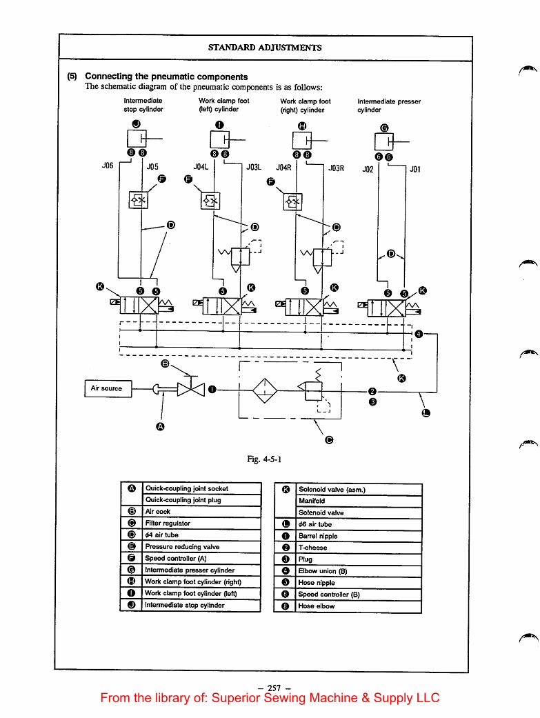
STANDARD ADJUSTMENTS
(5) Connecting the pneumatic componentsThe schematic diagram of the pneumatic components is as follows:
J06
Intermediate
stop cylinder
oo
J05
Work clamp foot(left) cylinder
o
QOO oo
J03L J04R
<9
J04L
<9 <9\
w
Work clamp foot(right) cylinder
Q
Intermediate pressercylinder
0@J03R J02 JOl
\A/ (i).
<9\_®©
Air source
o
< A
I '
- J
O \o
\o
Fig. 4-5-1
o Quick-coupling joint socket o Solenoid valve (asm.)
Quick-coupling joint plug Manifold
® Air cock Solenoid valve
o RIter regulator (9 46 air tube
<§) 44 air tube O Barrel nipple
o Pressure reducing valve o T-cheese
<9 Speed controller (A) o Plug
© Intermediate presser cylinder o Elbow union (8)
© Work clamp foot cylinder (right) 0 Hose nipple
o Work clamp foot cylinder (left) 0 Speed controller (B)
0 Intermediate stop cylinder 0 Hose elbow
- 257 -
From the library of: Superior Sewing Machine & Supply LLC
now TO ADJUST
o Connect the pneumatic components properly referring to theschematic diagram.
- 258 -
RESULTS OF IMPROPER
ADJUSTMENT
o Malfunction of the feeding famecomponents and intermediate pressercomponents may occur, resulting inmachine failure or giving damages to therelated components.
From the library of: Superior Sewing Machine & Supply LLC

DISASSEMBLY/ASSEMBLY PROCEDURES
(6) Installing the pedal switch (PK47)Refer to "(5) Installing the pedal switch (PK47)" for the AMS-215CSB and -215CHB(on page 233).
(7) Removing the slide plate bearing and work clamp slide plateRefer to page 99.
- 259 -
From the library of: Superior Sewing Machine & Supply LLC
CAUTIONS IN DISASSEMBLYCAUTIONS IN ASSEMBLY
- 260 -
From the library of: Superior Sewing Machine & Supply LLC
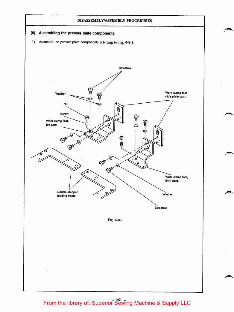
Washer
Work clamp foot,left asm.
DISASSEMBLY/ASSEMBLY PROCEDURES
(8) Assembling the presser plate components
1) Assemble the presser platecomponents referring to Fig. 4-8-1.
Setscrew
Double-steppedfeeding frame
Fig. 4-8-1
- 261 -
Work cictmpfootslide plate asm.
Work clamp foot,right asm.
Washer
Setscrew
From the library of: Superior Sewing Machine & Supply LLC

CAUTIONS IN DISASSEMBLY
o Be sure to tighten/loosen the adjustment screw in the feedingframe after the nut of the adjustment screw in the feeding framehas been loosened.
- 262 -
CAUTIONS IN ASSEMBLY
o After the presser plate components havebeen assembled, confirm that the feedingframe is laterally in parallel to (or theoutside edge of the feeding frame isslightly lower than) the throat platesurface.
From the library of: Superior Sewing Machine & Supply LLC

DISASSEMBLY/ASSEMBLY PROCEDURES
(9) Assembling the double-stepped stroke feeding frameRefer to the description given in "(6) Assembling thedouble-stepped stroke feeding frame" (page 235) of theEngineer's manual for the AMS-215CSB, -215CHB and -215CGB.
(10) Assembling the pneumatic componentsAssemble the pneumatic components referring to Fig. 4-10-1.
J 03L
J 03R
Speed controller
J04R
J 04L
Solenoid valve for workclamp foot (right)
Solenoid valve for
intermediate presserSolenoid valve for workclamp foot (left)
Solenoid valve for
Pressure reducing valve double-stepped stroke
Fig. 4-10-1
- 263 -
Solenoid valve cord asm.
J 78
From the library of: Superior Sewing Machine & Supply LLC

CAUnONS IN DISASSEMBLY
- 264 -
CAUnONS IN ASSEMBLY
o Solenoid valve asm. is provided withthree blanking plates ©. Use thesolenoid valve asm. with one of themremoved.
From the library of: Superior Sewing Machine & Supply LLC

DISASSEMBLY/ASSEMBLY PROCEDURES
(11) Connecting the solenoid valve connectors asm.Connect the respective cables of the solenoid valve connector asm. and solenoid valve connector A asm. tothe connectors ^79) of the solenoid valve cord asm. (See the figure below.)
F»79
1 m 2
[i^
33
P79
P79-3-
P79-4
P79-13-^
P79-14
Solenoid valvecord asm.
P91
P92
Red
Black
Fig. 4-11-1
- 265 -
Solenoid valve
connector A asm.
Solenoid valve
connector asm.
From the library of: Superior Sewing Machine & Supply LLC
CAUTIONS IN DISASSEMBLY CAUTIONS IN ASSEMBLY
- 266 -
From the library of: Superior Sewing Machine & Supply LLC

5. PARTS TO BE REPLACED WHEN CHANGING THE STANDARD TYPE MACHINE
TO THE DOUBLE-STEPPED FEEDING FRAME TYPE MACHINE
Parts to be removed
Name of part Q'ty Part No.
1 d4 air tube J 03 1 BT0400251EB
2 04 air tube J 04 1 BT0400251EB
3 Y joint 1 PJ308040002
4 Solenoid valve asm. 1 PV0351130A0
5 2-pedal unit asm. 1 M85905130A0
Parts to be additionally attached (Unit part No.: B26062150A0)
Name of part Q'ty Part No.
1 Solenoid valve conneaor A asm. 1 B4712215AA0
2 Solenoid valve conneaor asm. 1 B47122150A0
3 Solenoid valve 2 PV140501000
4 Nut 6 El626850000
5 Plastic blank for double-steppled feeding frame 4 B2618215000
6 Setscrew 6 SS2111010TP
7 Sctcw 4 SS7090410SP
8 Washer 6 WP0450000SD
9 Double-stepped stroke push plate 1 B2530215000
10 Double-steppedstroke cylinder 1 PA1602510A0
11 Hose nipple 2 PJ032052503
12 Retaining ring 2 RE0300000KO
13 Setscrew 1 SS6110520TP
14 Setscrew 2 SS6121010SP
15 Setscrew 2 SS8110422TP
16 Setscrew 2 SS8110422TP
17 Washer 1 WP0650876SD
18 Washer 1 WP0820816SD
19 Double-stepped stroke cylinder knuckle 1 B1625220000
20 Cylinderconnecting pin 1 B1626220000
21 Double-stepped stroke lever spacer 1 B185351200E
22 Height adjusting knob 1 B2304205000
23 Double-stepped stroke mounting plate 1 B2514215000
24 Double-stepped stroke lever 1 B2516215000
25 Height adjusting plate 1 B2518215A00
26 Double-stepped stroke adjusting screw bracket 1 B2518215000
27 Height adjustment screw 1 B2527215000
28 Double-stepped stroke fulcrum shaft 1 B2528215000
29 Flange bushing 1 B2548215000
30 Feed bracket asm. 1 B25502150AB
- 267 -
From the library of: Superior Sewing Machine & Supply LLC

Name of part Q'ty Part No.
31 Double-stepped stroke fulcrum shaft thrust collar 1 B25792290A0
32 Double-stepped feeding frame 2 B2606215000
33 Double-stepped strokelever fulcrum shaft 1 B3012490000
35 (64 air tube1.5" BT0400251EB
34 Heightadjusting plate stopper 1 B3012816000
36 Height adjusting screw thrust collar 1 CS0790731SH
• rans oi
Name of part Q'ty Part No.
1 Qip band7 — 8 HX002330000
2 Speed controller2 — 3 PC012401000
3 Pressure reducing valve1 — 2 PFD70501000
4 Hose nipple3 — 6 PJ032052503
- 268 -
From the library of: Superior Sewing Machine & Supply LLC

6. OPTIONS
Name of part
1. Machinable feeding frame
Type
Feeding frame (right) blank withknurl
Double-stepped feeding frameblank without knurl (Common toleft and right)
Feeding frame (left) blank withknurl
Separate type work clamp blankwith knurl
Separate type work clamp blankwithout knurl
Separate type plastic feedingframe blank
(Common to left and right)Screw
Screw
Washer
Nut
- 269 -
Part No.
B2622215000
B26262I5000
B2623215000
B2620215000
B2621215000
B2618215000
SS7090410SP
SS2111010TP
ffP0450000SD
B1626850000
Size (mm)
193x 135x4
193 X 135x4
A X B X t
193x 135x4
A X B X t
193x279x4
193x279x4
A X B X t
135x 190x3
From the library of: Superior Sewing Machine & Supply LLC

7. DIMENSIONS OF THE FEEDING FRAME
oil
e-
82.5 82.5
55 55
78
110
27.5
15.5
d4 hole/
- 270 -
Sewing area
Feed plate
in(MJ_
10
58
231 .5
Feed plate
1=^ /15/64 threads 28
From the library of: Superior Sewing Machine & Supply LLC

to-J
8. MATERIALS
8-1. Block diagram for the AMS-215CSL, -aiSCHL and -215CGL
SCALE
SEWINQ MACHINETHREAD THROUGH
SPEEO-VRDOOBIN-WINOER
JEn
P13 P23
P14 P24
LIGHT
1
POWER
SOURCE
PSS I 7P I PS1 I 7P |PS3| aPf P59l BP I
(PMDC
CPU pod
JS7
POWER PCB
PIS P2S
(PMDC)
PGM-EA)
J90
1/F PCB
12P
12P
J27IOIIO
)
J70 P79
M8803S2t0A0
PMDC
J77 P77 P76 J78
Q-l Id.
WHITE P7S
P71 JTI
«|(PQM-6A)
EU
SYNCHRONIZERSTOP SW
IElUEhlEEIlTH.BR
PJZ J73
sensor
Tiiner sei
WIpof evy
Y-PM
CLUTCH
BRAKE
0-1 POWER
PK47
MACHINE
)From the library of: Superior Sewing Machine & Supply LLC

to-jto
) ) )
8-2. Air valve schematic diagram for the AMS-215CSL, -215CHL and -215CGL
P34
+24VA
AIR OPRER(N)+24VA
air OPREL(N)
+24VA
AIR IPRE(N)
+24VA
AIR INVS(N)
+24VA
AIR WP(N)
+24VA
AIR TCLMP(N)
+24VA
AIR STROKE(N)
+24VA
air TR 3(N)
+ 24VA
AIR SW
GND
1
2
3
4
5
6
7
8
9
10
11
12
13
14
15
16
17
18
19
20
21
22
23
24
25
26
27
28
29
30
31
33
32
34
1
2
3
4
5
6
7
8
9
10
11
12
13
14
15
16
17
18
19
20
21
22
23
24
25
26
27
28
29
30
31
33
32
34
P^91
2
3
4
7
8
9
10
11
12
13
14
15
16
17
18
19
20
21
22
23
24
25
26
27
28
29
30
31
33
32
34
RED
BLACK
REDBLACK
RED
BLACK
RED
BLACK
RED
WHITE
BLACK
)
P91
+24VA
AIR OPRER(N)
+24VA
AIR OPREL(N)
+24VA
AIR IPRE(N)
P93
£92
P94
+24VA
AIR STROKE(N)
P78 J78RED
+24VA
AIR SW
GND
WHITE
BLACK
)
From the library of: Superior Sewing Machine & Supply LLC
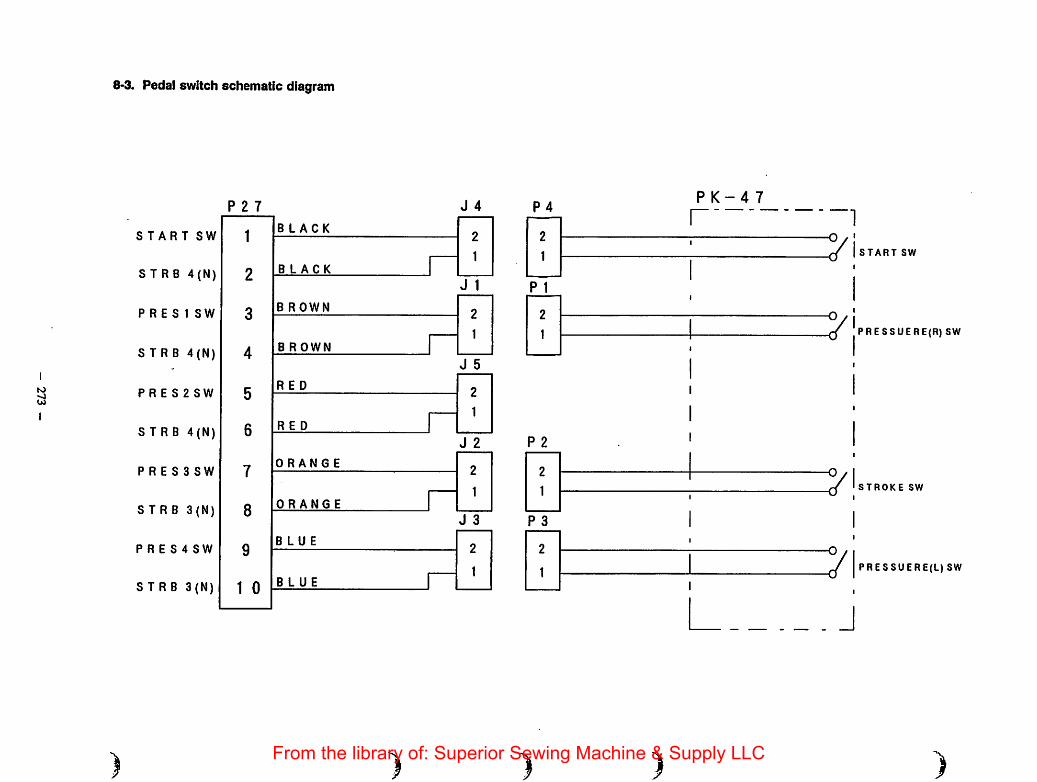
to
CO
8-3. Pedal switch schematic diagram
P 2 7
START SWBLACK
STRB 4(N) BLACK
P R E S1 SWB ROWN
STRB 4(N) B R OWN
P R E S 2 SWRED
STRB 4(N) RED
P R E S 3 SWORANGE
STRB 3(N) ORANGE
P R E S 4 SWBLUE
STRB 3(N) BLUE
J 4 P 4
P 1
P 2
P 3
) )
P K-4 7
I
START SW
PRESSUERE(R) SW
STROKE SW
PRESSUERE(L) SW
)From the library of: Superior Sewing Machine & Supply LLC
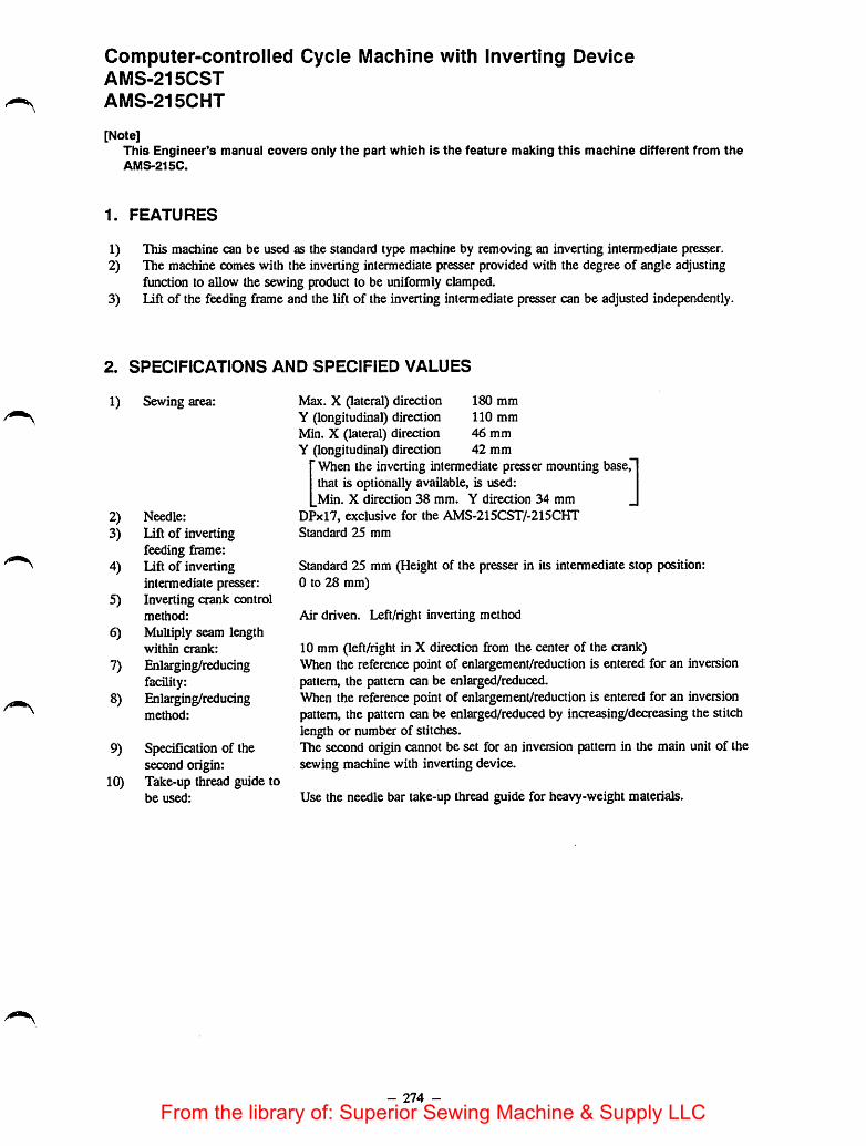
Computer-controlled Cycle Machine with Inverting DeviceAMS-215CST
AMS-215CHT
[Note]This Engineer's manual covers only the part which is the feature making this machine different from theAMS-215C.
1. FEATURES
1) This machine can be used as the standard type machine by removing an inverting intermediate presser.2) The machine comes with the inverting intermediate presser provided with the degree of angle adjusting
function to allow the sewing product to be uniformly clamped.3) lift of the feeding frame and the lift of the inverting intermediate presser can be adjusted independently.
2. SPECIFICATIONS AND SPECIFIED VALUES
1) Sewing area: Max. X (lateral) directionY (longitudinal) directionMin. X (lateral) directionY (longitudinal) direction
180 mm
110 mm
46 mm
42 mm
When the inverting intermediate presser mounting base,that is optionally available, is used:Min. X direction 38 mm. Y direction 34 mm
2) Needle: DPxl7, exclusive for the AMS-215CST/-215CHT
3) Lift of inverting Standard 25 mm
feeding frame:
4) Lift of inverting Standard 25 mm (Height of the presser in its intermediate stop position:intermediate presser: 0 to 28 mm)
5) Inverting crank controlmethod: Air driven. Left/right inverting method
6) Multiply seam lengthwithin crank: 10 mm (left/right in X direction fi-om the center of the crank)
7) Enlarging/reducing When the reference point of enlargement/reduction is entered for an inversionfacility: pattern, the pattern can be enlarged/reduced.
8) Enlarging/reducing When the reference point of enlargement/reduction is entered for an inversionmethod: pattern, the pattern can be enlarged/reduced by increasing/decreasing the stitch
length or number of stitches.
9) Specification of the The second origin cannot be set for an inversion pattern in the main unit of thesecond origin: sewing machine with inverting device.
10) Take-up thread guide tobe used: Use the needle bar take-up thread guide for heavy-weight materials.
- 274 -
From the library of: Superior Sewing Machine & Supply LLC
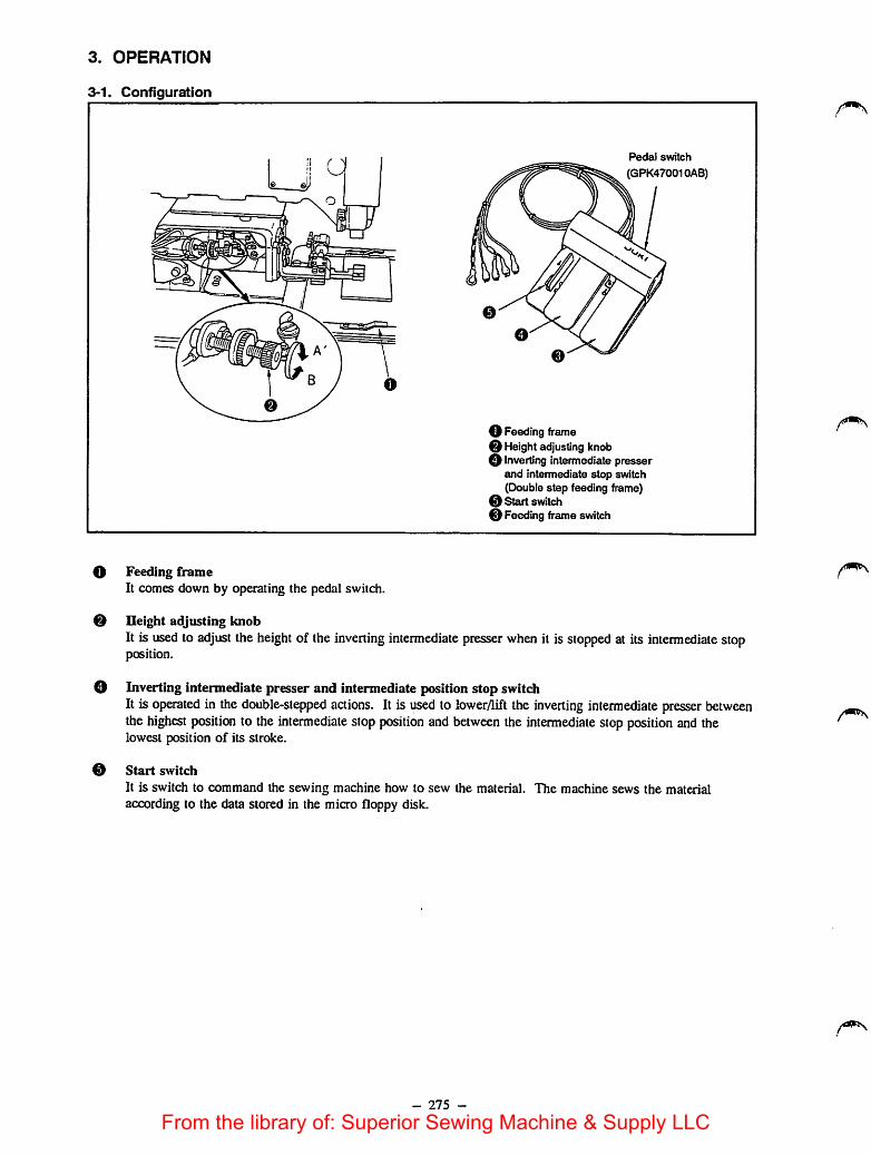
3. OPERATION
3-1. Configuration
o
0
0
Feeding frameIt comes down by operating the pedal switch.
Pedal switch
(GPK470010AB)
O Feeding frameo Height adjusting knobo Inverting intermediate presser
and intermediate stop switch(Double step feeding frame)
0 Start svntch0 Feeding frameswitch
Ileight adjusting knobIt is used to adjust the height of the inverting intermediate presser when it is stopped at its intermediate stopposition.
Inverting intermediate presser and intermediate position stop switchIt is operated in the double-stepped actions. It is used to lowerylift the inverting intermediate presser betweenthe highest position to the intermediate stop position and between the intermediate stop position and thelowest position of its stroke.
Start switch
It is switch to command the sewing machine how to sew the material. The machine sews the materialaccording to the data stored in the micro floppy disk.
- 275 -
From the library of: Superior Sewing Machine & Supply LLC

3-2. Explanation of operation panelName of switch
X Scale
(review)
Y Scale
(end)
Set Ready(Test)
Return to
Origin
••••BQ•E3nS[ S«( Beady
(Tcjt)
Function
If the reference point of enlargement/reduction is entered when creating an inversionpattern, the pattern created can be enlarged/reduced. At this time, be sure to specifythe scale paying attention not to allow the needle to come in contact with the feedingframe. • . .Ifthe reference point of enlargement/reduction for an inversion pattern is not entered,no pattern enlargement or reduaion is performed even if any scale other than 100% isset. Therefore, the display wiU automatically indicate 100%.
For anormal pattern, when apattern has been read out, the feeding frame comes downfrom the desired needle position and automatically moves to the sewing start point (ora2nd origin ifthe 2nd origin has been set) by way of the origin. For an inversionpattern, however, the method of searching the origin and the method of moving to thesewing start point are different from those for anormal pattern in order to prevent theinverting intermediate presser mounting base from interfering with the tip of the needle
For an inversion pattern, the method of returning to the origin or to the 2nd ongin isdifferent from that ofa normal pattern because ofthe need for preventing the invertingintermediate presser mounting base from coming in contact with the tip of the needle.
Since 2nd origin setting is prohibited for an inversion pattern in this model, no 2ndorigin setting can be performed even ifjog keys are operated.
3-3. How to use the PK47/3-pedal unit 1) Place the garmentbody under thefeeding frame anddepress pedalO, andthe feeding framewill come down to
secure the garmentbody. Anotherdepress on pedal Owill allow the
feeding frame to goup.
2) Put the label underthe invertingintermediate presserand lightly depresspedal ©, and theinverting
o
t
Feeding frame
Inverting 2)intermediate
presser
11©tst step
t© 2nd step
0
intermediate presser wiU stop in its intermediate stop position. Release the pedal in this state, and theinverting intermediate presser will return to the previous height.
3) PosiUon the label Further depress pedal ©, and the inverting intermediate presser will ^me ^own to helowest position of its stroke to secure the label FuUy depress pedal © again until it wiU go no further, andthe inverting intermediate presser will return to its intermediate position. . . ,
4) Depress pedal @when both the feeding frame and inverting intermediate presser rest in the lowest positionof its stroke, and the sewing machine will start sewing.
- 276 -
From the library of: Superior Sewing Machine & Supply LLC

3-4. Sewing with the inverting intermediate presser removed® When the double-stepped stroke function is not used
1) Set item 1 of function No. 43 of the memory switch to "0."2) Place the sewingproduct on the machine and depress f)edal
© of the pedal switch, and the feeding frame will comedown. Depress pedal © again, and the feeding frame willgo up.
3) Depress pedal @ when the feeding frame rests in thelowest position of its stroke, and the sewing machinewillstart sewing.
(D Whendouble-stepped stroke function is used
.'•.'r'-jyiJ-i
jut. Oj jttt.
IBU t© L
@ 1Ststep @ 2nd step
1) Set item 1 of function No. 43 of the memory switch to "1."2) Place thesewing product under the feeding frame and
slightly depress pedal © of the pedal switch, and thefeeding frame willstop when the intermediate position ofthe pedal is reached. Release the pedal, and thefeedingframe will return to the home position.
3) Accurately position the sewing product and further depresspedal ©, and the feeding frame comes down to the lowestposition of its stroke and secures thesewing product.Fully depress pedal © again until it will go nofurther, andthe feeding fiame will return to the intermediate position.
4) Depress pedal © when the feeding frame rests in thelowest position of its stroke, and the sewing machine willstart sewing.
3-5. Cautions to be taken when creating a pattern1. Jump input up to the 2nd origin
2. Setting the 2nd origin
Sewing start point
o o
25mm or more
2nd origin
2nd origin
Pressing the Set Ready switch will move the feeding frameto the 2nd origin after retrieving the origin. At this time,the inverting intermediate mounting base may come incontact with the needle. To prevent this, "jump" should beentered up to the 2nd origin as illustrated in the figure.
When the sewing start point is retrieved after completion ofsewing, the inverting crank rotates and the feeding framegoes up. At this time, the tip of the needle may come incontact with the inverting crank if the sewing start point isclose to the inverting crank. To prevent this, specify the2nd origin at the position which is 25 mm or more awayfrom the center of the inverting crank shaft using the offsetinput function, and then enter "jump" from the 2nd origin tothesewing start point. When the 2ndorigin has been set,the machine will return to the 2nd origin after completion ofsewing.
- 277 -
From the library of: Superior Sewing Machine & Supply LLC

3. Inputting the needle entry point near the crank shaft
6 mm
10.5"™
When the crank is inverted
• As a rule, the sewing area near the crank shaft and the inverting intermediatepresser mounting base is theportion indicated by attaching slanting line (^^). The sewing area in X (lateral) direction is not symmetrical.So, be careful.
[Caution]At this time, the sewing area will be as foliow:
Max. X (lateraO direction 180 mmY (longitudinal) direction 103 mm
Min. X (lateral) direction 46 mmY (longitudinal) direction 42 mm
When the optional inverting intermediate presser mounting base is used:Min. X (lateral) direction 38 mm
Y (longitudinal) direction 34 mm
If a needle entry point is entered outside the sewing area indicated above, the applicable thickness of the materialwill be 4 mm or less. At this time, the sewing area will be the portion indicated by attaching slanting lines(^^) ^ illustrated in the figure.
Radius of the needle..
/////^
o o
8mm
'^/TTTfTTTT/A
|8"/
\
Radius of the needle
When the crank inverted
[Caution]At this time, the sewing area will be as follows:Max. X (lateral) direction 180 mm
Y (longitudinal) direction 110 mmMin. X (lateral) direction 34 mm
Y (longitudinal) direction 32 mmWhen the optional inverting intermediate presser mounting base is used:Min. X (lateral) direction 26 mm
Y (longitudinal) direction 24 mmIf the thickness of the sewing product is 3.5 mm or less, multiply seam length within the crank is 22 mmat the maximum.
- 278 -
From the library of: Superior Sewing Machine & Supply LLC

4. When intermediate presser is used• As long as the thidmess of the material is 4 ram or less, the standard intermediate presser can be used. At this
time, however, the sewing area near the crankshaft and the inverting intermediate pressermounting base(indicated by attaching slanting lines ) will be different from the normal sewing areawhen theintermediate presseris used. So be careful. When using the intermediate presser, changeover the settingof thememoryswitch (function No. 44) to the set value 1 (intermediate presser operation is effective.)
Center of the crank-
in Y direction
I
J_L dnim
IQtiun
L_rH IQmm
I8™n4(nm
o o
y/////AVTTTTTTT^,Center of the crank in X direction
400)
^cU
Center of the crank
in Y direction
When the crank is inverted.
[Caution]At this time, the sewing area will be as follows:Max. X (lateral) direction 180 mm
Y (longitudinal) direction 107 mmMin. X (laterai) direction 54 mm
Y (longitudinal) direction 41.5 mmr When the optionai inverting intermediate presser mounting base is used:
Min. X (lateral) direction 46 mm|_ Y(longitudinal) direction 33.5 mm
If the thickness of the material used is 4 mm or more, the intermediate presser cannot be used.
3-6. Controlling the inverting crank
20. bmm
For an inverting pattern by automatic inversion functionWhen sewing from the back end toward the front of thematerial, the inverting crank shaft inverts when theneedle entry passes line Cwhich is 20.5 mm behind theorigin.For an inverting pattern by the voluntary invertingfunction
The inverting crank shaft inverts at the point ofinversion which has been entered on the pattern. Notethat the inverting crank shaft does not invert on line C.
[Caution]For the voluntary inverting function, the point of inversion on the created pattern data can be specified asyou wish. However, the inverting crank will face to the left at the sewing start and will then turn to theright ^ at the first of inversion point. After that, it will turn in alternate directions at every point of ^inversion. Consequently, the specified number of points of inversion should be an odd number. If an evennumber isspecified, the inverting crank will face to the left (^ . As a result, the crank may come incontact with the needle at the sewing end causing the needle to break.
- 279 -
From the library of: Superior Sewing Machine & Supply LLC
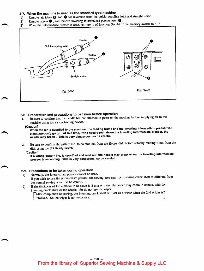
3-7. When the machine Is used as the standard type machine1) Remove air tubes O and O for inversion from the quick- coupling joint and straight union.2) Remove screw O , and remove inverting intermediate presser asm. O •3) When the intermediate presser is used, set item 1of function No. 44 of the memory switch to 1.
0Quick-coupling joint
Yellow —
straight union
Fig. 3-7-1 Fig. 3-7-2
3-8. Preparation and precautions to betaken before operation1. Be sure to confirm that the needle has not attached in place on the machine before supplying air to the
machine using the air controlling device.
^ When the air is supplied to the machine, the feeding frame and the Inverting Intermediate presser willsimultaneously go up. At this time, If the needle rest above the Inverting Intermediate presser, theneedle may break . This Is very dangerous, so be careful.
2. Be sure to confirm the pattern No. to be read out from the floppy disk before actually reading it out from thedisk using the Set Ready switch.
^^^lfa°wrong pattern No. Is specified and read out, the needle may break when the Inverting Intermediatepresser Is ascending. This is very dangerous, so be careful.
3-9.
1)
2)
Precautions to be taken during operationNormally, the intermediate presser cannot be used. . .If you wish to use the intermediate presser, the sewing area near the inverting crank shaft is different fromthe normal sewingarea. So be careful.If the thickness ofthe material to be sewn is 2 mm or more, the wiper may come in contaa with theinverting crank shaft or the needle. So do not use the wiper,
rAfter completion of sewing, the inverting crank shaft will act as awipier when the 2nd origin is"j|_retrieved. So the wiper is not necessary. J
- 280 -
From the library of: Superior Sewing Machine & Supply LLC

4. ADJUSTMENTS4-1. Adjusting the mechanical components
STANDARD ADJUSTMENTS
(1) Height of the needle barAdjust so that the upper marker line (for DPxl7) engraved on the needle bar is aligned with the bottomend of the lowerbushing of the needle bar when the needle bar is in its lowest dead point.(Forthe sewing machine provided with an inverting device, use a DPxl7 needle.)
Fig. 4-1-1
- 281 -
Needle bctr
lower bushing
inesMarker lines
for DPx17
Fig. 4-1-2
From the library of: Superior Sewing Machine & Supply LLC
now TO ADJUST
1) Turn ON the needle threading switch (the READY indicatorlamp lights up). Then turn the handwheel by hand to bring theneedle down to its lowest position.
2) Remove plug O in the cover of the face plate.3) Loosen needle bar conneaionscrew O. Then adjust the height
of theneedle barby moving needle bar O up and down.4) After the adjustment, be sure to tighten screw ©.5) Turn OFF the needle threading switch. (The needle bar will
return to its highest position.)6) Attach plug © in the cover of the face plate.
- 282 -
RESULTS OF IMPROPER
ADJUSTMENT
o Stitch skipping or thread breakagemay result.
From the library of: Superior Sewing Machine & Supply LLC

STANDARD ADJUSTMENTS
(2) Adjusting the degree of angle of the inverting intermediate presserIf the inverting intermediate presser is in parallel to the throat plate, the pressure of the front side of theinverting intermediate presser is likely to drop. Consequently, be sure to adjust the inclination of theinverting intermediate presser so that the front side of the inverting intermediate presser is slightly lowerthan its rear side.
Throat platesurface
2mm :
Fig. 4-2-1
Fig. 4-2-2
- 283 -
From the library of: Superior Sewing Machine & Supply LLC

now TO ADJUST
1) Loosen screw O 2nd nut ®. Turning adjustment screw 0clockwise will lower the front side of the inverting intermediatepresser.
2) After the adjustment, securely tighten screw O 2nd nut 0.
[Caution]As reference of the adjustment, the rear end of the invertingintermediate presser should be approximately 2 mm abovethe throat plate surface whenthe front end of the Invertingintermediate presser meets the throat plate surface.
- 284 -
RESULTS OF IMPROPERADJUSTMENT
If the inverting intermediate presser isnot sufficiently tilted, the work pressingforce at the front side of the invertingintermediatepresser may drop.If the inverting intermediate presser isexcessively tilted, trouble may resultsuch as the inverting crank shaft fails torotate and the inverting intermediatepresser fails to go up.
From the library of: Superior Sewing Machine & Supply LLC
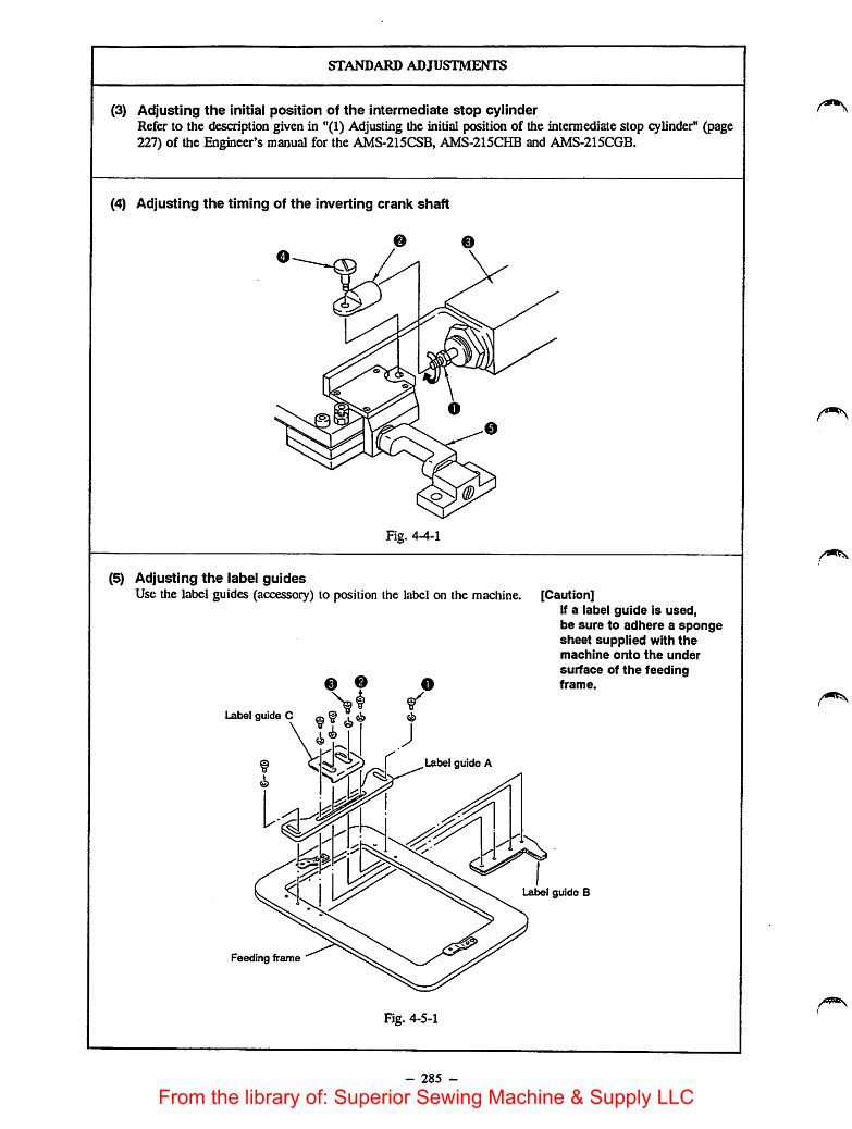
STANDARD ADJUSTMENTS
(3) Adjusting the initial position of the intermediate stop cylinderRefer to the description given in "(1) Adjusting the initial position of the intermediate stop cylinder" (page227) of the Engineer's manual for the AMS-215CSB, AMS-215CHB and AMS-215CGB.
(4) Adjusting the timing of the inverting crank shaft
e e
Fig. 4-4-1
(5) Adjusting the label guidesUse the label guides (accessory) to position the label on the machine. [Caution]
If a label guide is used,be sure to adhere a spongesheet supplied with themachine onto the under
surface of the feedingframe.
Lxibel guide C q ^ ^
Lxtbel guide A
l.at>el guide B
Feeding frame
Fig. 4-5-1
- 285 -
From the library of: Superior Sewing Machine & Supply LLC

now TO ADJUST
1) Turn nut O in the direction of the arrow until it will go nofurther.
2) Attach inverting cylinderknuckle O onto cylinder0-Fully turn the knuckle until it is securely fixed in place.
3) Tighten hinge screw O, and make inverting crank shaft 0invert to the right.
4) Turning nut O using a wrench in the direaion of the arrowwill make the cylinder shaft turn, thereby changing the timingof inverting crank shaft 0.
5) Once the timing of the inverting crank shaft 0 has beenadjusted to allow the inverting crank shaft to turn to the rightand left in the uniform timing, turn nut O in the oppositedirection of the arrow to fix inverting cylinder knuckle 0 inplace.
1) Loosen screwsO, and adjust the position of label guide (A) tothe leftmost end of the label. Then tighten screws O •
2) Loosen saews 0, and adjust the position of label guide (B) tothe top end of the label. Tlien tighten screws 0.
[Caution]If positioning a small-sized label on the machine, label guide(A) may come into contact with the inverting unit. In thiscase, use label guide (0) instead of label guide (A).
286 -
RESULTS OF IMPROPER
ADJUSTMENT
o If the timing of the inverting crank shafthas not been properly adjusted, theinverting crank shaft may come incontact with the inverting intermediatepresser when the shaft inverts.
From the library of: Superior Sewing Machine & Supply LLC

(6)
(7)
STANDARD ADJUSTMENTS
Adjusting the intermediate stop position of the inverting intermediate presserAdjust the height of the intermediate stop position of the inverting intermediate presser to allow theoperator to position the sewing product on the machine with ease.
Fig. 4-6-1
Adjust the clearance between theinverting intermediate presser and thesewing product on the machine toapproximately 1 mm.(The intermediate stop position of theinverting intermediate presser can beadjusted within the range of 0 through30 mm above the top surface of thethroat plate.)
Finely adjusting the X-Y originAdjust the origin and the traveling end in the X-Y directions using the origin gauge.1) Remove the inverting intermediate presser foot (asm.).2) Then, finely adjust the X-Y origin referring to the description given in "(33)-l Fine adjustment of the
X/Y origins" (page 65) of the Engineer's manual for the AMS-215C.
Quick-coupling joint
Straight union
Fig. 4-7-1
Yellow
- 287 -
D=]
o
Fig. 4-7-2
From the library of: Superior Sewing Machine & Supply LLC

now TO ADJUST
1) Loosen knob O-2) Turn knob 0 to adjust the intermediate stop position of the
feeding frame slightly higher than the material thickness. Turnknob 0 in direction A to heighten the intermediate stop positionof the feeding frame or in direction B to lower it.
3) Securely tighten knob O.[Caution]
Only the Inverting intermediate presser is capable ofstoppingat the intermediate position.
1) Remove air tubes O and 0foFinve£^iiTrom the quick-coupling joint and strai^t uoiiDn:.
2) Remove screws ©, and remove-iEwertirig^ intermediate presserasm. O-
- 288 -
RESULTS OF IMPROPERADJUSTMENT
o If the intermediate stop position of thefeeding frame is too high, the materialmaynot be positioned on the machinewith ease.
o If the intermediate stop position of thefeeding frame is too low, the materialcannot be smoothly moved on themachine.
From the library of: Superior Sewing Machine & Supply LLC

(8)
STANDARD ADJUSTMENTS
Adjusting the pneumatic components1) Connea quick-coupling joint O in place and open air cock 0 . Thepressure gauge O indicates 5 to
5S kgf/cm^ (0.5 MPa to 0.55 MPa). (Fig. 4-8-1)2) If pressure gauge O indicates 4 kgf/cm" (0.4 MPa) or lower value, the machine will stop with Error
0 shown on theoperation panel. (Fig. 4-8-1)3) The air pressure on the feeding frame cylinder retraaing side and the intermediate stop cylinder
extrudingside has been reduced to 1 to 1.5 kgf/cm" (0.1 MPa to 0.15 MPa). (Fig. 4-8-2)4) The air pressure on the inverting intermediate presser cylinder retracting side has been reduced to 1 to
1.5kgf/cm^ (0.1 MPa to 0.15 MPa). (Fig. 4-8-2)5) The needle knob of the speed controller (for feeding frame) cylinder has been fixed at the position that
is reached by loosening the knob by one turn after fully tightening it. (Fig. 4-8-3)6) The needle knob of the speed controller (B) (for the intermediate presser cylinder) is fixed usinga nut
with loosened by 5 turns after it has been fully tightened. (Fig. 4-8-4)
o9 9
0
1 to 1.5 kgf/cm^ (0.1 to 0.15 MPa)
Air hose for double-
stepped stroke cylinder
Fig. 4-8-1
Fig. 4-8-2
Number
Panern No
XScafe
SMtfifyp# ISpoeO
Y Scale
1 to 1.5 kgf/cm' (0.1 to 0.15 MPa)
Solenoid valve (eism.)
Air hose for work
clamp cylinder, left
Air hose for work
clamp cylinder, right
Fig. 4-8-3
- 289 -
Intermediate pressercylinder (asm.)
Fig. 4-8-4
From the library of: Superior Sewing Machine & Supply LLC

now TO ADJUST
1) Open air cock ©. Pull up air adjusting knob ©, then turn ituntil pressure gauge © indicates 5 to 5.5 kgf/cm^ (0.5 MPa to0.55 MPa). Then push down the knob to fix it at that position.(Fig. 4-8-1)
2) Set the machine in its sewing state. Now remove the air hose bypressing section © of pressure reducing valve O which isfixed on the solenoid valve (asm.), and connect a commerciallyavailable pressure gauge instead of the removed air hose. (Fig.4-8-2)Depress the feeding frame switch 5 times or more, and turnneedle knob © of pressure reducing valve O until theconnected pressure gauge indicates 1 to 1.5kgf/cm^ (0.1 MPa to0.15 MPa). Then fix the needle knob using nut ©, and removethe pressure gauge. Now, securely connect the removed air hosein place. (Fig. 4-8-2)
3) Following the procedure same as described in step 3), depressthe intermediate stop switdi 5 times or more, and adjust so thatthe connected pressure gauge indicates 1 to 1.5kgf/cm^ (0.1MPa to 0.15 MPa).
4) Referring to the Standard adjustment (8)-5), properly adjustneedle knob © of speed controller O and fix the knob with nut®. (Fig. 4-8-3)
5) Remove the top cover.Referring to the Standard adjustment (8)-6), properly adjustneedle knob © of speed controller © and fix the knob with nut©. (Fig. 4-8-4)
- 290 -
RESULTS OF IMPROPER
ADJUSTMENT
1) Function failure of the feeding framecomponents and intermediate pressercomponents may result.The machine stops with Error 0indicated on the operation panel.
2) An adequate work pressing pressure isnot provided.
3) The feeding frame may fail to go upuntil its highest position is reached.
4) The speed of vertical motion of thefeeding frame may be too high or toolow.
5) The intermediate presser may fail tomove smoothly, or it may generates akeen metallic noise when it is in
operation.[Caution]
Normally, Standard adjustments (8)-2)through -6) are not required to beadjusted. Needle knobs and nutsreferred In steps 3) through 6), Inparticular, have applied with oil-resistant white coating material toshow that they have been alreadyadjusted properly.
* To set the air pressure to 0 kgf/cm%close air cock © and press button ©.(Fig. 4-8-1)
From the library of: Superior Sewing Machine & Supply LLC

STANDARD ADJUSTMENTS
(9) Connecting the pneumatic components
<9
Invertingcylinder
o
Qoo
o o
El
intermediate
stop cylinderWork clamp foot(left) cylinder
Work clamp foot(right) cylinder
o
Q
Intermediate
presser cylinder
JOB
QOO
J05 J04L
<9 <9\
(9
Q-OO OO
J03L J04R J03R J02
o
a-eo
J01
W
V
(9 o (9
•<^i:
w
V
iji
<9
(S*1^ x|
2E AA 2E IZE AA IZl
Air source
J..L
© r
o
Fig. 4-9-1
\
</
u J
OO
<9
(9
OQuick-couplinq joint socket (Si M air tube
Quick-coupling joint plug © Inverting cylinder tube
© Air cock © Inverting relay tube
© Filter regulator O Barrel nipple
© Pressure reducing valve o T-cheese
© Speed controller (A) o Plug
© Intermediate presser cylinder o Hose nipple
© Work clamp foot cylinder (right) 0 Speed controller
© Work clamp foot cylinder (left) 0 Y joint
o Inverting cylinder o Hose elbow
© Intermediate stop cylinder 0 Elbow union (8)
©
Solenoid valve (asm.) 0 Quick-coupling joint
Manifold m Inverting relay joint
Solenoid valve (D Inverting relay joint (8)
© ^6 air tube
- 291 -
©-1
\
From the library of: Superior Sewing Machine & Supply LLC

now TO ADJUST
o Connect the pneumatic components properly referring to theschematic diagram.
- 292 -
RESULTS OF IMPROPER
ADJUSTMENT
o Malfunction of the feeding framecomponents and intermediate pressercomponents may occur, resulting inmachine failure or giving damages tothe related components.
From the library of: Superior Sewing Machine & Supply LLC

DISASSEMBLY/ASSEMBLY PROCEDURES
(10) Installing the pedal switch (PK47)Refer to "(5) Installing the pedalswitch (PK47)" for the AMS-215CSB, AMS-215CHB andAMS-215CGB (on page 233).
(11) Removing the slide plate bearing and work clamp slide plateRefer to page 99.
- 293 -
From the library of: Superior Sewing Machine & Supply LLC
CAUnONS IN DISASSEMBLY CAUTIONS IN ASSEMBLY
- 294 -
From the library of: Superior Sewing Machine & Supply LLC

DISASSEMBLY/ASSEMBLY PROCEDURES
(12) Assembling the inverting intermediate presser asm.1) Assemble the inverting intermediate presser asm. referring to Fig. 4-12-1.2) Attach the inverting intermediate presser using the screws in the inverting intermediate presser to
section ©
Invertingintermediate
presser
Setscrew
Needle (A) ^
Washer
Inverting crankshaft bracket
Needle (B)
Washer
Setscrew Hingescrew
/ Inverting (Green)
Inverting rackI
Inverting crankshaft
Fig. 4-12-1
Hose elbow
©
Inverting cylinder tube
(Yellow)
Inverting cylinder
Inverting cylinder knuckle
Setscrew
Inverting rackreceiving plate
Inverting intermediatepresser mounting base
Washer
Needle
(13) Assembling the double-stepped stroke feeding frameRefer to the description given in "(6) Assembling the double-stepped stroke feeding frame" (page 235) ofthe Engineer's manual for the AMS-215CSB and AMS-215CHB.
- 295 -
From the library of: Superior Sewing Machine & Supply LLC

CAUTIONS IN DISASSEMBLY
Do not pick up the inverting cylinder shaft with a tool, etc.
[Caution]The screws in the inverting intermediate presser and thewashers of the screws in the inverting intermediate presserare not included in the inverting intermediate presser asm.
- 296 -
CAUTIONS IN ASSEMBLY
Attach the inverting cylinder so that thehose elbow faces away from you.Do not pick up the inverting cylindershaft with a tool, etc.
Apply grease tosection ©.
From the library of: Superior Sewing Machine & Supply LLC
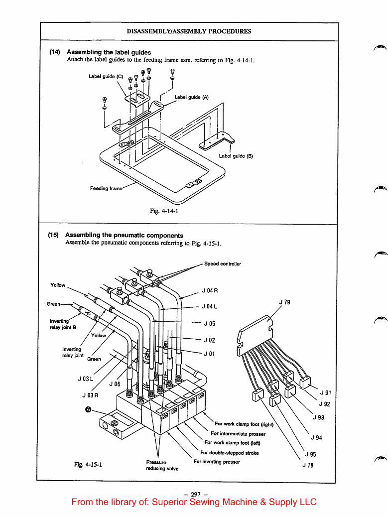
DISASSEMBLY/ASSEMBLY PROCEDURES
(14) Assembling the label guidesAttach the label guides to the feeding frame asm. referring to Fig. 4-14-1.
Ubel guide (C) @f T^ ©
I Isabel guide (A)
Label guide (B)
Feeding frame
Fig. 4-14-1
(15) Assembling the pneumatic componentsAssemble the pneumatic components referring to Fig. 4-15-1.
Yellow
Green
Invertingrelay joint B
Yellow
Invertingrelay joint
J03L
J 03R
Fig. 4-15-1
-i
Pressure
reducing valve
Speed controller
J 04R
J 04L
- 297 -
For work clamp foot
For intermediate presser
For work cleunp foot (left)
For double-stepped stroke
For Invert'ng presser
J79
From the library of: Superior Sewing Machine & Supply LLC

CAUTIONS IN DISASSEMBLY
- 298 -
CAUTIONS IN ASSEMBLY
[Caution]If a label guide is used, be sure toadhere a sponge sheet supplied withthe machine onto the under surface of
the feeding frame.
o Solenoid valve asm. is provided withthree blanking plates Q. Use thesolenoid valve asm. with one of them
removed.
From the library of: Superior Sewing Machine & Supply LLC
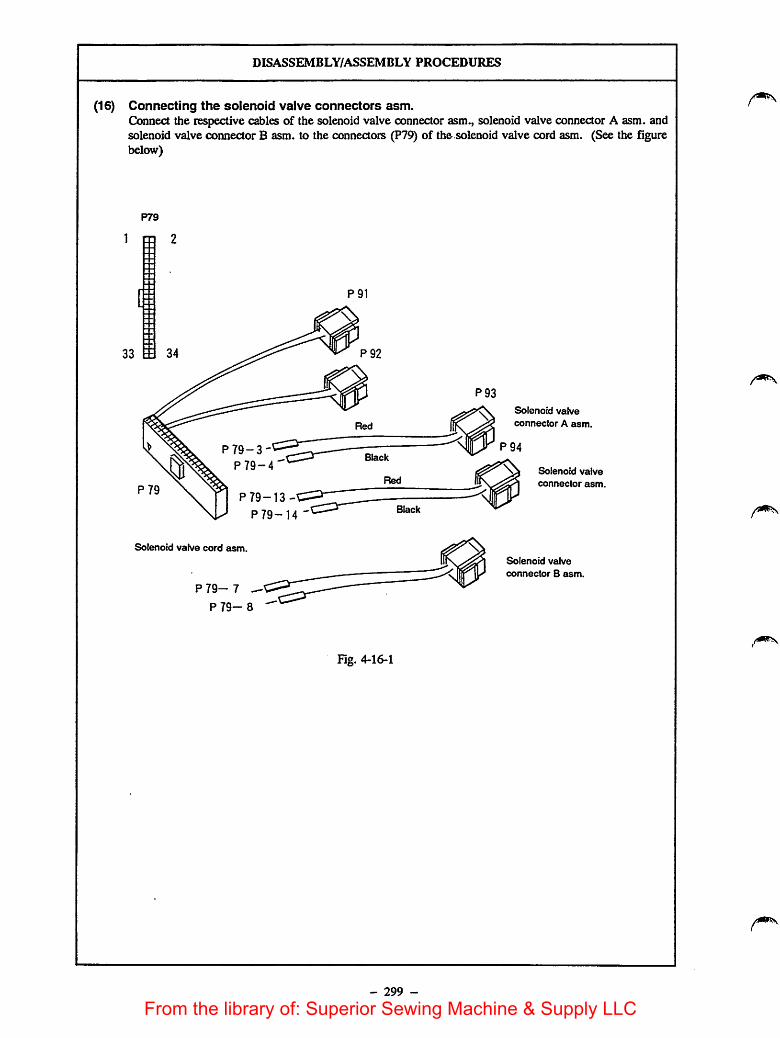
DISASSEMBLY/ASSEMBLY PROCEDURES
(16) Connecting the solenoid valve connectors asm.Connect the respective cables of the solenoid valve connector asm., solenoid valve connector A asm. andsolenoid valve connector B asm. to the connectors (P79) of the solenoid valve cord asm. (See the figurebelow)
P79
1 m 2
[ii
33
IP79
P79-3-
P79-4
P 79-13-
P79-14
Solenoid valve cord asm
P79- 7
P79- 8
P91
Fig. 4-16-1
- 299 -
Solenoid valve
connector A asm.
Solenoid valve
connector asm.
Solenoid valve
connector B asm.
From the library of: Superior Sewing Machine & Supply LLC
CAUTIONS IN DISASSEMBLY CAUTIONS IN ASSEMBLY
300 -
From the library of: Superior Sewing Machine & Supply LLC

5. PARTS TO BE REPLACED WHEN CHANGING THE STANDARD TYPE MACHINE
TO THE INVERTING DEVICE TYPE MACHINE (Refer to page 295,297,299)
Parts to be removed
Name of part Q'ty Part No.
1 Y joint - PJ308040002
2 04 air tube J 03 - BT0400251EB
3 04 air tube J 04 - BT0400251EB
4 Work clamp foot right asm. - B26042150A0
5 Work clamp foot left asm.- B26052150A0
6 Feeding frame arm- B2552220000
7 Feeding frame - B2553215000
8 Feed plate- B2556215000
9 Solenoid valve asm.- PV0351130A0
10 Needle #14- MDP500B1400
11 Needle bar take-up thread guide A - B1405210000
12 Intermediate presser- B1601220000
13 Screw- SS7091110SP
14 2-pedal unit asm.- M85905130AA
Parts to be additionally attached (Unit part No.: B43012150B0)
Name of part Q'ty Part No.
1 Double-stepped stroke cylinder knuckle 1 B1625220000
2 Cylinder connecting pin 1 B1626220000
3 Double-stepped stroke lever spacer 1 B185351200E
4 Height adjusting knob 1 B2304205000
5 Double-stepped stroke mounting plate 1 B2514215000
6 Double-stepped stroke lever 1 B2516215000
7 Height adjusting plate 1 B2518215A00
8 Height adjusting screw bracket 1 B2518215000
9 Screw 1 B2527215000
10 Double-stepped stroke fulcrum shaft 1 B2528215000
11 Feed bracket asm. 1 B25502150AB
12 Feed plate for inverting 1 B2556215A00
13 Double-stepped stroke fulcrum shaft thrust collar 1 B25792290A0
14 Double-stepped stroke lever fulcrum shaft B3012490000
15 Height adjusting plate stopper 1 B3012816000
16 04 air tube 1 BT0400251EB
17 Height adjusting screw thrust collar 1 CS0790731SH
18 Height adjusting plate sleeve 1 E5006171000
19 Needle DP x 17 #14 1 MDP170B1400
20 Needle bar take-up thread guide for heavy-weight materials 1 B1406210000
21 Inverting intermediate presser asm. 1 B43012150A0
22 Setscrew 2 SS7151210SP
- 301 -
From the library of: Superior Sewing Machine & Supply LLC
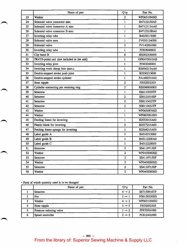
Name of part Q'ty Part No.
23 Washer 2 WP0651056SD
24 Solenoid valve connector asm. 1 B47122150A0
25 Solenoid valve connector A asm. 1 B4712215AA0
26 Solenoid valve conneaor B asm. 1 B4712215BA0
27 Inverting relay tube 1 B4329215000
28 Solenoid valve asm. 1 PV0351240B0
29 Solenoid valve 2 PV140501000
30 Inverting relay tube 1 PJ303040002
31 Clip band B 8 HX002330000
32 PK47/3-pedal unit (not included in the unit) 1 GPK470010AB
33 Inverting relay joint 1 PJ303040004
34 Inverting work clamp foot (asm.) 1 B2604215AA0
35 Double-stepped stroke push plate 1 B2530215000
36 Double-stepped stroke cylinder 1 PA1602510A0
37 Hose nipple 2 PJ032052503
38 Cylinder connecting pin retaining ring 2 RE0300000KO
39 Setscrew 1 SS6110520TP
40 Setscrew 2 SS6121010SP
41 Setscrew 2 SS8110422TP
42 Setscrew 2 SS8110422TP
43 Washer 1 WP0650876SD
44 Washer 1 WP0820816SD
45 Feeding frame for inverting 1 B2553215A00
46 Plastic blank for inverting 2 B2557215AC0
47 Feeding frame sponge for inverting 1 B2564215A00
48 Label guide A 1 B4310215000
49 Label guide B 1 B43112200A0
50 Label guide C 1 B4312220000
51 Setscrew 2 SS4110715SP
52 Washer 2 WP0450000SD
53 Setscrew 2 SS4110715SP
54 Washer 2 WP0450000SD
55 Setscrew 2 SS4110715SP
56 Washer 2 WP0450000SD
• Parts of which quantity used is to be changed
Name of part Q'ty Part No.
1 Setscrew 4-* 2 SS7150910TP
2 Nut 2 — 1 NS6150330SD
3 Washer 4 — 2 WP0651056SD
4 Hose nipple 3 — 5 PJ032052503
5 Pressure reducing valve 1 — 2 PF070501000
6 Speed controller 2 — 3 PC012401000
- 302 -
From the library of: Superior Sewing Machine & Supply LLC

6. OPTIONS
Name of part
1. Intermediate presser mountingbase
2. Crank shaft
3. Machinable invertingintermediate presser
Type
Inverting intermediate pressermounting base B
It is necessary when theinverting intermediate presserblank, small (B4319220000) isused.
Screw
Inverting crank shaft B
Inverting intermediate presserplate blank with knurl, large
Inverting intermediate presserplate blank with knurl, medium
Inverting intermediate presserplate blank with knurl, small[It required the inverting "1
intermediate presser mountinglbase B (B4316220000). J
- 303 -
Part No.
B4616220000
SS1090750SP
B4326220000
B43I7220000
B4318220000
B4319220000
Size (mm)
A X B X t
8x24x 15
A X B X 0 C
26x71 X 7
A X B X t
122x206x 2.6
100x 126x2.6
50 X 80x 2.6
From the library of: Superior Sewing Machine & Supply LLC

7. WHEN MANUFACTURING AN INVERTING INTERMEDIATE PRESSER
1) If you use the standard inverting intermediate presser mounting base (B4320220000), be sure to drill attachingholes in the inverting intermediate presser as illustrated.
90* 90*
2.6mm
5.4!isn
22nini
5. 4inm
2) If you use the optional inverting incennediate presser mounting base B(B4316220000), be sure to drill attachingholes in the inverting intermediate presser as illustrated.
120*
0. CJI3
3
120*
2.6mm
4mm 4mm
18mm
[Caution]1. Determine thelocation oftheattaching holes to bedrilled, considering the needle entry near the invertmg
crank shaft. (Refer to the descriptrcm: given In '3. Inputting the needle entry point near the crank shaft".)(See page 278.)
2. If the inverting intermediate presseiriistftrcker than 2.6 mm, the applicable material thickness will be 4 mmor less.
- 304 -
From the library of: Superior Sewing Machine & Supply LLC
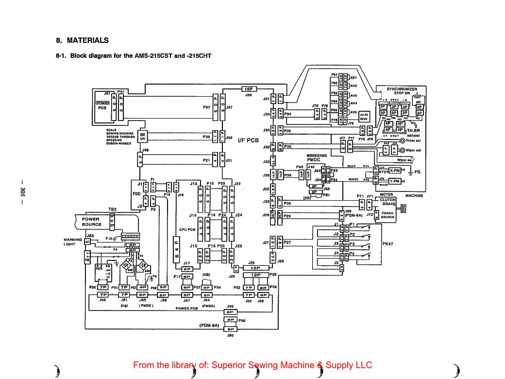
o
8. MATERIALS
8-1. Block diagram for the AMS-215CST and -215CHT
SCALE
SEWING MACHINE
THREAD THROUGH8PECD-VReOBOIN-WINDER
PI3 P23
l/F PCS
P14 P24 TJ24
LIGHT
)
POWER
SOURCE
PSS I 7P i P5ll 7P IPtal ap| P59| BP I
(PMOC)
CPU PCS
POWER PCS
)
P1S P25
JS4
(PMOCI
(PGM-SA)
o P27
" J28
12P
P52 I -T-P I I eF» |PS6
JS2 JS6
J78 P79
MS6035210A0PMDC
P62 |J62
)
§]
a
aa
J77 P77 P7S
WHITE P7S
P7t J71
SYNCHRONIZERSTOP SW ^x OXOI -X
4PhH4P hTH.BR
sensor
I^TIfnof sol
:©wiper sol
Wiper sy
IfGY-PM
MOTOR
CLUTCH
BRAKE
MACHINE
J89
a>l(PQM-6A) J720)1 SOURCE
>)3^r-iP3 PK47
J4 P,i-iP4
)From the library of: Superior Sewing Machine & Supply LLC

Oo>
)
8-2. Air valve schematic diagram for the AMS-215CST and -215CHT
P34
+24VA 1 -
AIR OPRER(N} 2 -
+24VA 3 -
AIR OPREL(N) 4 -
+24VA 5 -
AIR IPRE(N) 6 -
+24VA 7 -
AIR INVS(N) 8 -
+24VA 9 -
AIR WP{N) 10 -
+24VA 11 -
AIR TCLMP(N) 12 -
+24VA 13 -
AIR STROKE(N) 14 -
IS -
16 -
17 -
18 -
19 -
20 -
21 -
22 -
23
24
25
26
+24VA 27
AIRTR 3(N) 28
29
30
31
+24VA 33
AIR SW 32
GND 34
J79 P79
1 1
2 2
3 3
4 4
5 5
6 6
7 7
8 8
9 9
10 10
11 11
12 12
13 13
14 14
15 15
16 16
17 17
18 18
19 19
20 20
21 21
22 22
23 23
24 24
25 25
26 26
27 27
28 28
29 29
30 30
31 31
33 33
32 32
34 34
RED
BLACK
RED
BLACK
RED
BLACK
RED
BLACK
RED
BLACK
RED
WHITE
BLACK
)
P91
P93
P92
P95
+24VA
AIR OPRER(N)
+24VA
AIR OPREL(N)
+24VA
AIR IPRE(N)
+ 24VA
AIR INVS(N)
P94
+24VA
AIR STROKE(N)
P78J78
2 +24VA 2
1 MR SW 1
4 QND 4
3 3
RED
WHITE
black;
J
From the library of: Superior Sewing Machine & Supply LLC
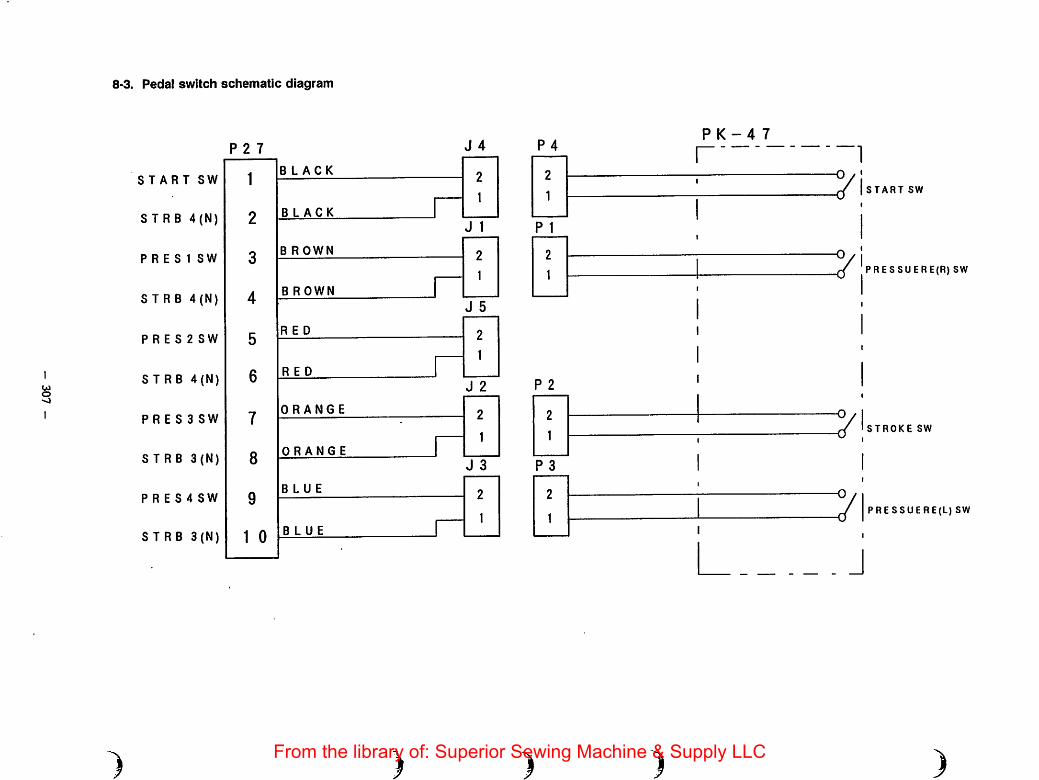
O
8-3. Pedal switch schematic diagram
START SW
S T R B 4(N)
P R E 8 1 SW
S T R 8 4(N)
P R E S 2 SW
STRB 4(N)
P R E S 3 SW
STRB 3(N)
P R E S 4 SW
STRB 3(N)
P 2 7 J 4
1BLACK 9
1
2BLACK
J 1
3B R OWN 2
1
4B ROWN
J 5
5
6
RED 2
RED
1
J 2
7ORANGE 2
1
8ORANGE
J 3
9BLUE 2
1
1 0BLUE
)
P 4
P 1
P 2
P 3
)
PK-4 7
I
START SW
PRESSUERE(R) SW
71 STROKE SW
71 PRESSUERE(L) SW
I
)From the library of: Superior Sewing Machine & Supply LLC

aJUKI
^jg CORPORATIONINTERNATIPNAL SALES DiViSiON8-2-.1. KGKURYO-CHO.CHOFO-^HI. TOKYO 182. JAPANPHONE: 03(3430)4001-5FAX; 03(3430)4903.4309.4914TELEX;J22967
Please do not hesitate to contact our distributors in your area for further infomation when necessary.♦ The specifications and appearance are subject to change without notice.From the library of: Superior Sewing Machine & Supply LLC
Related Documents


