Engineering Specifications derived from Science Requirements Advanced Mirror Technology Development (AMTD) Project 1 https://ntrs.nasa.gov/search.jsp?R=20140003111 2018-06-07T23:50:29+00:00Z

Welcome message from author
This document is posted to help you gain knowledge. Please leave a comment to let me know what you think about it! Share it to your friends and learn new things together.
Transcript
Engineering Specifications
derived from Science
Requirements
Advanced Mirror Technology Development
(AMTD) Project
1
https://ntrs.nasa.gov/search.jsp?R=20140003111 2018-06-07T23:50:29+00:00Z
Introduction
2

AMTD
Advanced Mirror Technology Development (AMTD) is a multi-
year effort to systematically mature to TRL-6 the critical
technologies needed to produce 4-m or larger flight-qualified
UVOIR mirrors by 2018 so that a viable mission can be
considered by the 2020 Decadal Review.
This technology must enable missions capable of both general
astrophysics & ultra-high contrast observations of exoplanets.
To accomplish our objective,
• We use a science-driven systems engineering approach.
• We mature technologies required to enable the highest
priority science AND result in a high-performance low-cost
low-risk system.
3
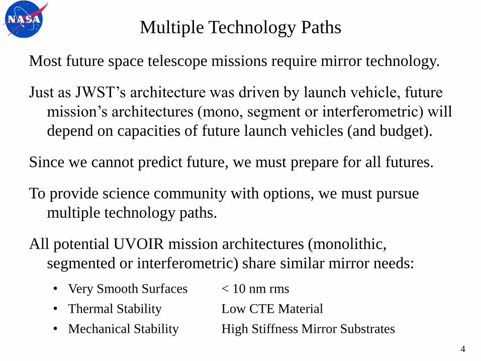
Multiple Technology Paths
Most future space telescope missions require mirror technology.
Just as JWST’s architecture was driven by launch vehicle, future
mission’s architectures (mono, segment or interferometric) will
depend on capacities of future launch vehicles (and budget).
Since we cannot predict future, we must prepare for all futures.
To provide science community with options, we must pursue
multiple technology paths.
All potential UVOIR mission architectures (monolithic,
segmented or interferometric) share similar mirror needs:
• Very Smooth Surfaces < 10 nm rms
• Thermal Stability Low CTE Material
• Mechanical Stability High Stiffness Mirror Substrates
4

Critical Technologies
Space telescopes require advances in 6 inter-linked technologies:
• Large-Aperture, Low Areal Density, High Stiffness Mirrors: 4 - 8 m monolithic
& 8 - 16 m segmented primary mirrors require larger, thicker, stiffer substrates.
• Support System: Large-aperture mirrors require large support systems to ensure
they survive launch and deploy on orbit in a stress-free and undistorted shape.
• Mid/High Spatial Frequency Figure Error: A very smooth mirror is critical for
producing a high-quality point spread function (PSF) for high-contrast imaging.
• Segment Edges: Edges impact PSF for high-contrast imaging applications,
contributes to stray light noise, and affects the total collecting aperture.
• Segment-to-Segment Gap Phasing: Segment phasing is critical for producing a
high-quality temporally stable PSF.
• Integrated Model Validation: On-orbit performance determined by mechanical
and thermal stability. Future systems require validated performance models.
5
Simultaneous Maturation
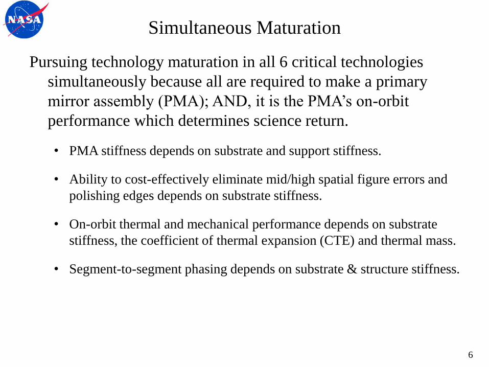
Pursuing technology maturation in all 6 critical technologies
simultaneously because all are required to make a primary
mirror assembly (PMA); AND, it is the PMA’s on-orbit
performance which determines science return.
• PMA stiffness depends on substrate and support stiffness.
• Ability to cost-effectively eliminate mid/high spatial figure errors and
polishing edges depends on substrate stiffness.
• On-orbit thermal and mechanical performance depends on substrate
stiffness, the coefficient of thermal expansion (CTE) and thermal mass.
• Segment-to-segment phasing depends on substrate & structure stiffness.
6
Engineering Specification
7
Engineering Specification
To meet our goals, we need to derive engineering specifications
for future monolithic or segmented space telescope based on
science needs & implementation constraints.
We use a science-driven systems engineering approach:
To derive specifications, we assembled an outstanding team from
academia, industry, & government with expertise in
• UVOIR astrophysics and exoplanet characterization,
• monolithic and segmented space telescopes, and
• optical manufacturing and testing.
Science Requirements Engineering Specifications
8
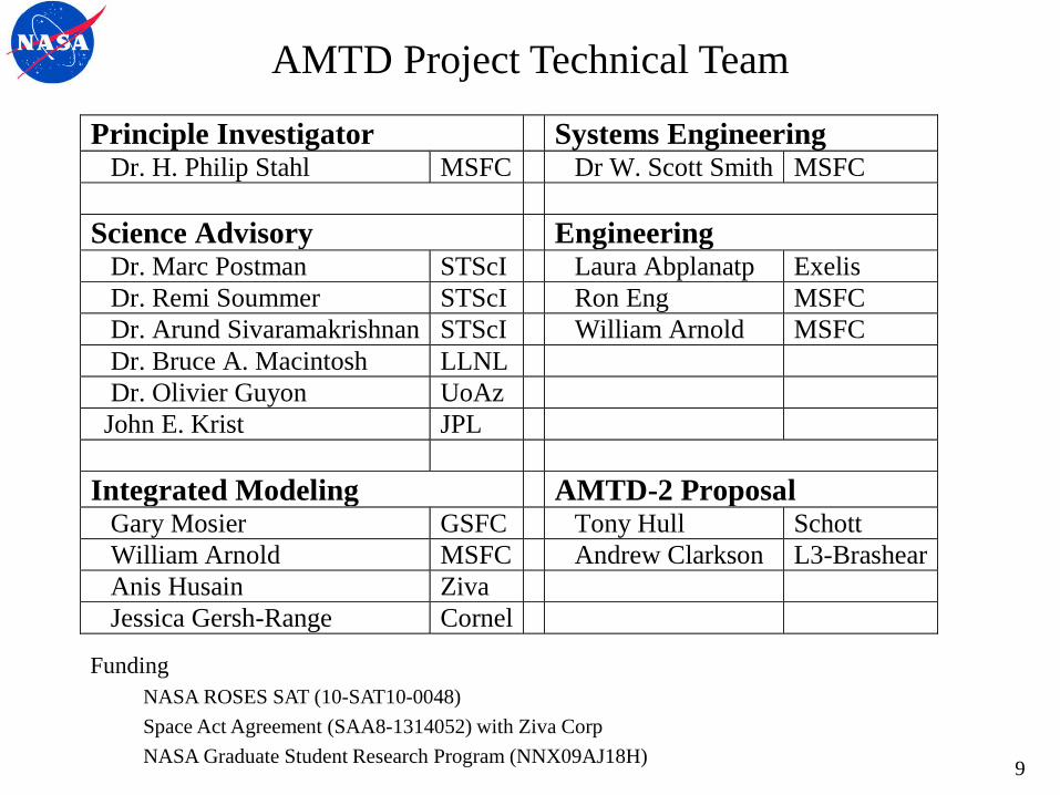
AMTD Project Technical Team
Principle Investigator Systems Engineering Dr. H. Philip Stahl MSFC Dr W. Scott Smith MSFC
Science Advisory Engineering Dr. Marc Postman STScI Laura Abplanatp Exelis
Dr. Remi Soummer STScI Ron Eng MSFC
Dr. Arund Sivaramakrishnan STScI William Arnold MSFC
Dr. Bruce A. Macintosh LLNL
Dr. Olivier Guyon UoAz
John E. Krist JPL
Integrated Modeling AMTD-2 Proposal Gary Mosier GSFC Tony Hull Schott
William Arnold MSFC Andrew Clarkson L3-Brashear
Anis Husain Ziva
Jessica Gersh-Range Cornel Funding
NASA ROSES SAT (10-SAT10-0048)
Space Act Agreement (SAA8-1314052) with Ziva Corp
NASA Graduate Student Research Program (NNX09AJ18H)
9
AMTD Team
Science & Engineering work collaboratively to insure that we
mature technologies required to enable highest priority science
AND result in a high-performance low-cost low-risk system.
• derive engineering specifications for monolithic & segmented mirrors
which provide on-orbit science performance needs AND satisfy
implementation constraints
• identify technical challenges in meeting these specifications,
• iterate between science needs and engineering specifications to mitigate
the challenges, and
• prioritize technology development which yields greatest on-orbit
performance for lowest cost and risk.
STOP (structural, thermal, optical performance) models are used
to help predict on-orbit performance & assist in trade studies.
10
Disclaimer
The purpose of this effort is NOT to design a specific telescope
for a specific mission or to work with a specific instrument.
We are not producing an optical design or prescription.
We are producing a set of primary mirror engineering
specifications which will enable the on-orbit telescope
performance required to enable the desired science.
Our philosophy is to define a set of specifications which
‘envelop’ the most demanding requirements of all potential
science. If the PM meets these specifications, it should work
with most potential science instrument.
Also, Coatings are out of scope.
11
Science Requirements
12
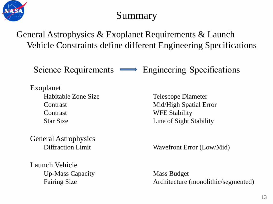
Summary
General Astrophysics & Exoplanet Requirements & Launch
Vehicle Constraints define different Engineering Specifications
Exoplanet
Habitable Zone Size Telescope Diameter
Contrast Mid/High Spatial Error
Contrast WFE Stability
Star Size Line of Sight Stability
General Astrophysics Diffraction Limit Wavefront Error (Low/Mid)
Launch Vehicle Up-Mass Capacity Mass Budget
Fairing Size Architecture (monolithic/segmented)
13
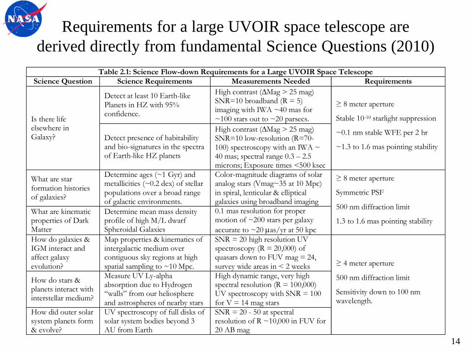
Requirements for a large UVOIR space telescope are
derived directly from fundamental Science Questions (2010)
Table 2.1: Science Flow-down Requirements for a Large UVOIR Space Telescope
Science Question Science Requirements Measurements Needed Requirements
Is there life elsewhere in Galaxy?
Detect at least 10 Earth-like Planets in HZ with 95% confidence.
High contrast (Mag > 25 mag) SNR=10 broadband (R = 5) imaging with IWA ~40 mas for ~100 stars out to ~20 parsecs.
≥ 8 meter aperture
Stable 10-10 starlight suppression
~0.1 nm stable WFE per 2 hr
~1.3 to 1.6 mas pointing stability Detect presence of habitability and bio-signatures in the spectra of Earth-like HZ planets
High contrast (Mag > 25 mag) SNR=10 low-resolution (R=70-100) spectroscopy with an IWA ~ 40 mas; spectral range 0.3 – 2.5 microns; Exposure times <500 ksec
What are star formation histories of galaxies?
Determine ages (~1 Gyr) and metallicities (~0.2 dex) of stellar populations over a broad range of galactic environments.
Color-magnitude diagrams of solar analog stars (Vmag~35 at 10 Mpc) in spiral, lenticular & elliptical galaxies using broadband imaging
≥ 8 meter aperture
Symmetric PSF
500 nm diffraction limit
1.3 to 1.6 mas pointing stability
What are kinematic properties of Dark Matter
Determine mean mass density profile of high M/L dwarf Spheroidal Galaxies
0.1 mas resolution for proper motion of ~200 stars per galaxy
accurate to ~20 as/yr at 50 kpc
How do galaxies & IGM interact and affect galaxy evolution?
Map properties & kinematics of intergalactic medium over contiguous sky regions at high spatial sampling to ~10 Mpc.
SNR = 20 high resolution UV spectroscopy (R = 20,000) of quasars down to FUV mag = 24, survey wide areas in < 2 weeks ≥ 4 meter aperture
500 nm diffraction limit
Sensitivity down to 100 nm wavelength.
How do stars & planets interact with interstellar medium?
Measure UV Ly-alpha absorption due to Hydrogen “walls” from our heliosphere and astrospheres of nearby stars
High dynamic range, very high spectral resolution (R = 100,000) UV spectroscopy with SNR = 100 for V = 14 mag stars
How did outer solar system planets form & evolve?
UV spectroscopy of full disks of solar system bodies beyond 3 AU from Earth
SNR = 20 - 50 at spectral resolution of R ~10,000 in FUV for 20 AB mag
14

Exoplanet Measurement Capability
Exoplanet characterization places the most challenging demands
on a future UVOIR space telescope.
Science Question Science Requirements Measurements Needed
Is there life elsewhere
in the Galaxy?
Detect at least 10 Earth-like
Planets in HZ with 95%
confidence if EARTH = 0.15
High contrast (Mag>25 mag)
SNR=10 broadband (R=5)
imaging with IWA ~ 40 mas
for ~100 target stars.
Detect the presence of
habitability and bio-signatures
in the spectra of Earth-like HZ
planets
High contrast (Mag>25 mag)
SNR=10 low-resolution
(R=70-100) spectroscopy with
an IWA ~ 40 mas. Exposure
times <500 ksec.
15

Aperture Size Specification
16

Aperture Size
Telescope Aperture Size is driven by:
• Habitable Zone Resolution Requirement
• Signal to Noise Requirement
• EARTH
• Exo-Zodi Resolution Requirement
17

Aperture Size vs Habitable Zone Requirement
Search for Exo-Earths (i.e. terrestrial mass planets with life)
requires ability to resolve habitable zone (region around star
with liquid water).
Different size stars (our Sun is G-type) have different diameter
zones (ours extends from ~0.7 – 2 AU; Earth is at 1 AU).
Direct Detection requires angular resolution ~ 0.5x HZ radius at
760 nm (molecular oxygen line is key biomarker for life).
Spectral Class
on Main
Sequence
Luminosity (Relative to Sun)
Habitable
Zone Location (AU)
Angular
radius of HZ
at 10 pc (mas)
Telescope
Diameter (meters)
M 0.001 0.022 – 0.063 2.2 – 6.3 90
K 0.1 0.22 – 0.63 22 – 63 8.9
G 1.0 0.7 – 2.0 70 – 200 2.7
F 8.0 1.98 – 5.66 198 – 566 1.0
Mountain, M., van der Marel, R., Soummer, R., et al. Submission to NRC ASTRO2010 Decadal Survey, 2009 18
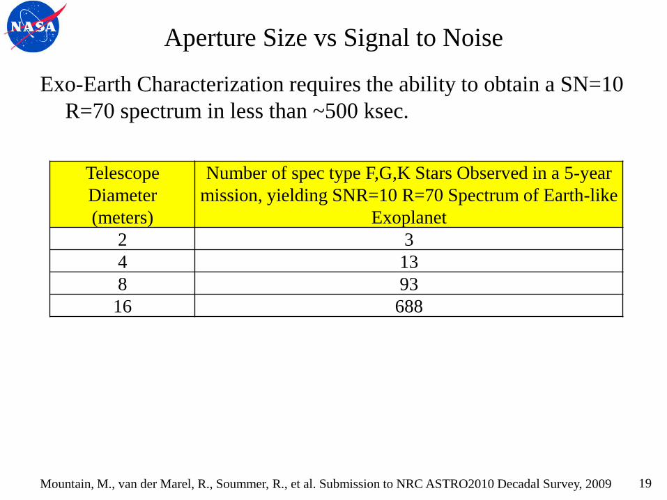
Aperture Size vs Signal to Noise
Exo-Earth Characterization requires the ability to obtain a SN=10
R=70 spectrum in less than ~500 ksec.
Telescope
Diameter
(meters)
Number of spec type F,G,K Stars Observed in a 5-year
mission, yielding SNR=10 R=70 Spectrum of Earth-like
Exoplanet 2 3 4 13 8 93
16 688
Mountain, M., van der Marel, R., Soummer, R., et al. Submission to NRC ASTRO2010 Decadal Survey, 2009 19

Aperture Size vs Habitable Zone and SNR
Lyon & Clampin looked at the number of stars in the TPF-C data
base out to 30 parsecs whose Habitable Zone would be outside
the Inner Working Angle for different diameter telescopes.
Δt is total time in days required to obtain SNR=5 R=5 (550 nm;
FWHM 110) spectrum for N stars (assuming eta_Earth = 1)
Lyon & Clampin, “Space telescope sensitivity and controls for exoplanet imaging”, OE 011002-2, Jan 2012. 20
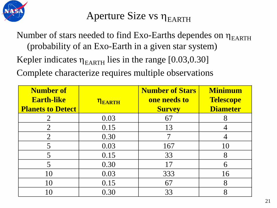
Aperture Size vs EARTH
Number of stars needed to find Exo-Earths dependes on EARTH
(probability of an Exo-Earth in a given star system)
Kepler indicates EARTH lies in the range [0.03,0.30]
Complete characterize requires multiple observations
Number of
Earth-like
Planets to Detect EARTH
Number of Stars
one needs to
Survey
Minimum
Telescope
Diameter 2 0.03 67 8 2 0.15 13 4 2 0.30 7 4 5 0.03 167 10 5 0.15 33 8 5 0.30 17 6
10 0.03 333 16 10 0.15 67 8 10 0.30 33 8
21
Aperture Size vs Exo-Zodi Requirement
Detecting & Characterizing an Exo-Earth, requires ability to
resolve an Exo-Earth in a planetary debris disc.
Planetary debris disc produces scattered or zodical light.
Being able to resolve an Exo-Earth in a system with up to 3X
more zodical light than our own systems requires:
• Sharp (high resolution) PSF for increased contrast of planet
relative to its zodi disk.
Thus, the larger the aperture the better.
Also, constrains mid-spatial frequency wavefront error
22
Aperture Size Recommendation
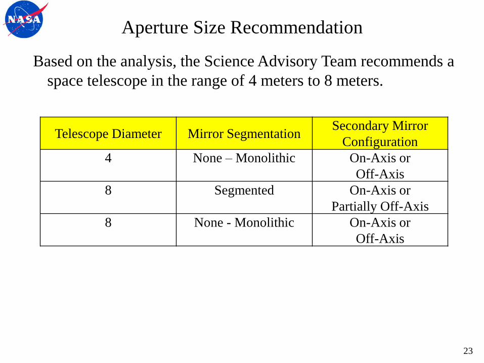
Based on the analysis, the Science Advisory Team recommends a
space telescope in the range of 4 meters to 8 meters.
Telescope Diameter Mirror Segmentation Secondary Mirror
Configuration 4 None – Monolithic On-Axis or
Off-Axis 8 Segmented On-Axis or
Partially Off-Axis 8 None - Monolithic On-Axis or
Off-Axis
23

Wavefront & Surface Figure Error Specification
24
Wavefront Error
Total system wavefront error (WFE) is driven by:
• 500 nm Diffraction Limited Performance
• Dark Hole Speckle
Exoplanet science driven specifications include:
• Line of Sight Pointing Stability
• Total Wavefront Error Stability
25
WFE vs 500 nm Diffraction Limit
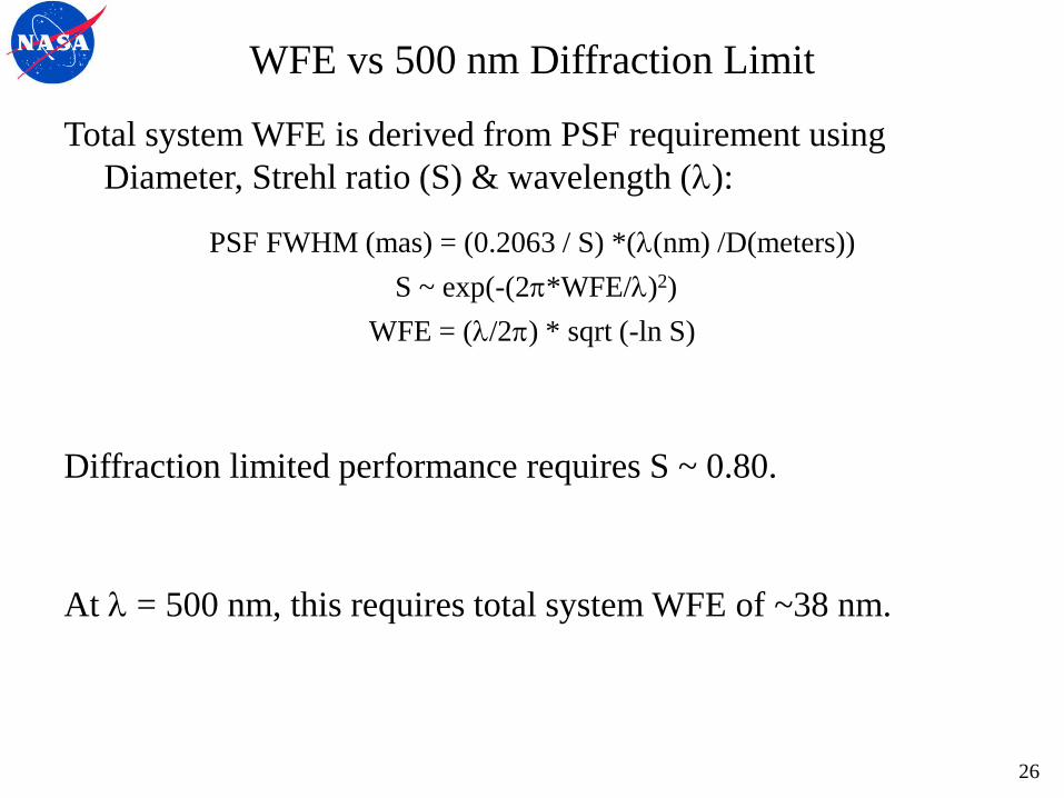
Total system WFE is derived from PSF requirement using
Diameter, Strehl ratio (S) & wavelength ():
PSF FWHM (mas) = (0.2063 / S) *((nm) /D(meters))
S ~ exp(-(2*WFE/)2)
WFE = (/2) * sqrt (-ln S)
Diffraction limited performance requires S ~ 0.80.
At = 500 nm, this requires total system WFE of ~38 nm.
26
Primary Mirror Total Surface Figure Requirement
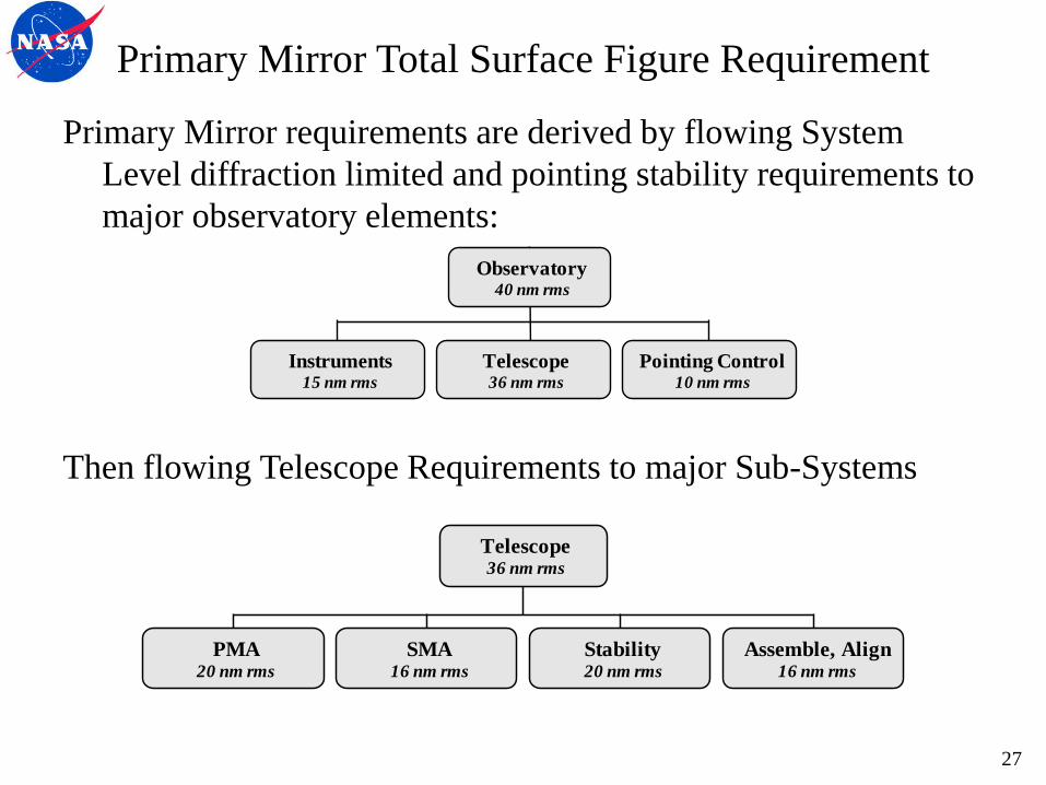
Primary Mirror requirements are derived by flowing System
Level diffraction limited and pointing stability requirements to
major observatory elements:
Then flowing Telescope Requirements to major Sub-Systems
Instruments15 nm rms
Pointing Control10 nm rms
Telescope36 nm rms
Observatory40 nm rms
SMA16 nm rms
Assemble, Align16 nm rms
PMA20 nm rms
Stability20 nm rms
Telescope36 nm rms
27
Primary Mirror Total Surface Figure Requirement
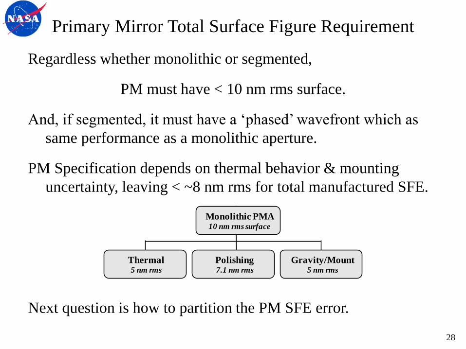
Regardless whether monolithic or segmented,
PM must have < 10 nm rms surface.
And, if segmented, it must have a ‘phased’ wavefront which as
same performance as a monolithic aperture.
PM Specification depends on thermal behavior & mounting
uncertainty, leaving < ~8 nm rms for total manufactured SFE.
Next question is how to partition the PM SFE error.
Thermal5 nm rms
Gravity/Mount5 nm rms
Polishing7.1 nm rms
Monolithic PMA10 nm rms surface
28
PM Manufacturing Specification
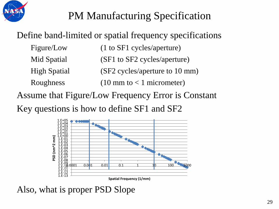
Define band-limited or spatial frequency specifications
Figure/Low (1 to SF1 cycles/aperture)
Mid Spatial (SF1 to SF2 cycles/aperture)
High Spatial (SF2 cycles/aperture to 10 mm)
Roughness (10 mm to < 1 micrometer)
Assume that Figure/Low Frequency Error is Constant
Key questions is how to define SF1 and SF2
Also, what is proper PSD Slope
1.E-131.E-121.E-111.E-101.E-091.E-081.E-071.E-061.E-051.E-041.E-031.E-021.E-011.E+001.E+011.E+021.E+031.E+041.E+05
0.0001 0.001 0.01 0.1 1 10 100 1000
PSD
(n
m^2
mm
)
Spatial Frequency (1/mm)
29
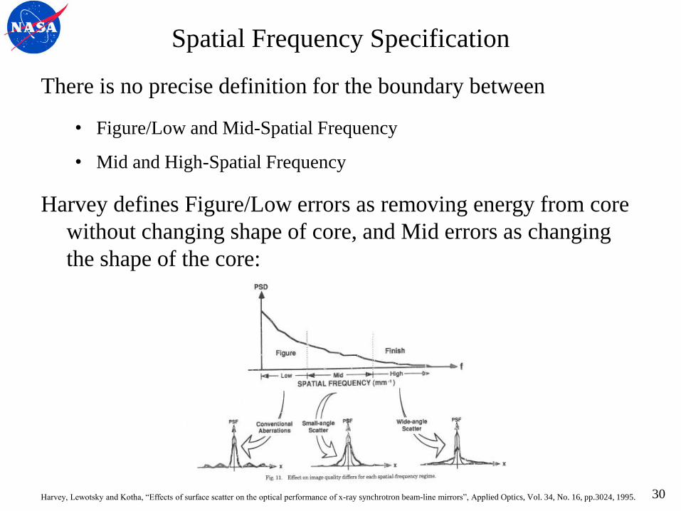
Harvey, Lewotsky and Kotha, “Effects of surface scatter on the optical performance of x-ray synchrotron beam-line mirrors”, Applied Optics, Vol. 34, No. 16, pp.3024, 1995.
Spatial Frequency Specification
There is no precise definition for the boundary between
• Figure/Low and Mid-Spatial Frequency
• Mid and High-Spatial Frequency
Harvey defines Figure/Low errors as removing energy from core
without changing shape of core, and Mid errors as changing
the shape of the core:
30
Spatial Frequency vs Exoplant Science
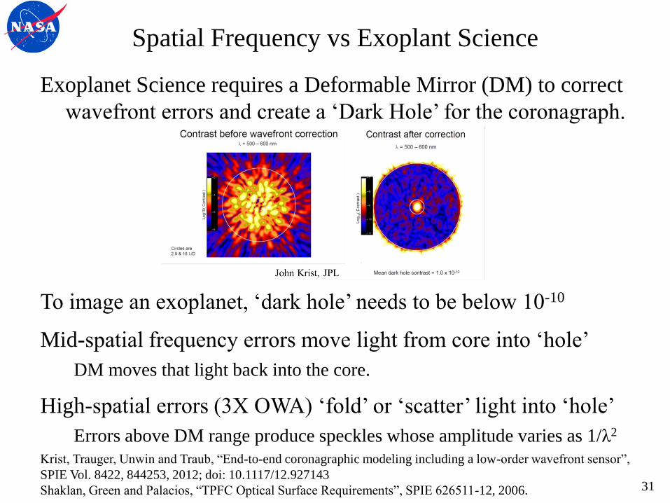
Exoplanet Science requires a Deformable Mirror (DM) to correct
wavefront errors and create a ‘Dark Hole’ for the coronagraph.
To image an exoplanet, ‘dark hole’ needs to be below 10-10
Mid-spatial frequency errors move light from core into ‘hole’
DM moves that light back into the core.
High-spatial errors (3X OWA) ‘fold’ or ‘scatter’ light into ‘hole’
Errors above DM range produce speckles whose amplitude varies as 1/λ2
Krist, Trauger, Unwin and Traub, “End-to-end coronagraphic modeling including a low-order wavefront sensor”,
SPIE Vol. 8422, 844253, 2012; doi: 10.1117/12.927143
Shaklan, Green and Palacios, “TPFC Optical Surface Requirements”, SPIE 626511-12, 2006. 31
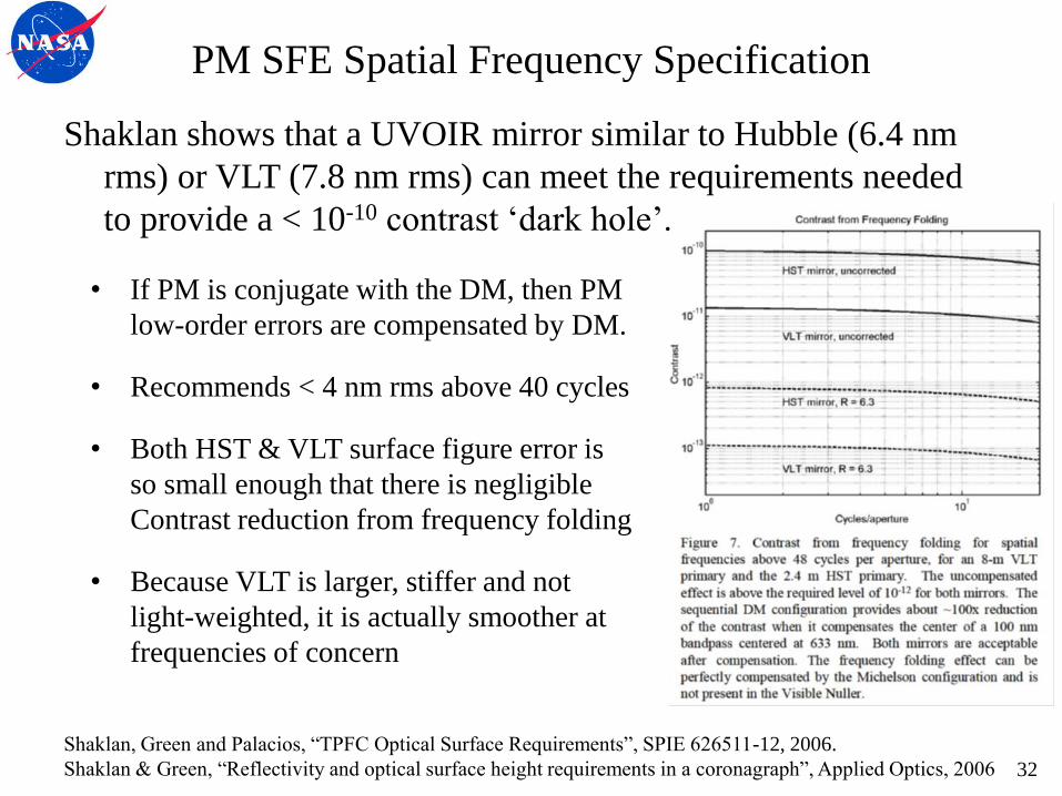
PM SFE Spatial Frequency Specification
Shaklan shows that a UVOIR mirror similar to Hubble (6.4 nm
rms) or VLT (7.8 nm rms) can meet the requirements needed
to provide a < 10-10 contrast ‘dark hole’.
• If PM is conjugate with the DM, then PM
low-order errors are compensated by DM.
• Recommends < 4 nm rms above 40 cycles
• Both HST & VLT surface figure error is
so small enough that there is negligible
Contrast reduction from frequency folding
• Because VLT is larger, stiffer and not
light-weighted, it is actually smoother at
frequencies of concern
Shaklan, Green and Palacios, “TPFC Optical Surface Requirements”, SPIE 626511-12, 2006.
Shaklan & Green, “Reflectivity and optical surface height requirements in a coronagraph”, Applied Optics, 2006 32
Spatial Frequency vs Science
Low spatial frequency specification is driven by General
Astrophysics (not Exoplanet) science.
Exoplanet instruments have deformable mirrors to correct low-spatial
errors and General Astrophysics instruments typically do not.
Mid/High spatial frequency specification is driven by Exoplanet
because of ‘leakage’ or ‘frequency folding’.
For exoplanet, the spatial band is from the inner working angle
(IWA) to approximately 3X the outer working angle (OWA).
Theoretically, a 64 x 64 DM can correct spatial frequencies up to
32 cycles per diameter (N/2), therefore, the maximum mid-
spatial frequency of interest is ~ 90 cycles.
Since mirrors are smooth & DM controllability rolls-off near N/2
limit, a conservative lower limit is ~N/3 or ~20 cycles.
33
Mid-Spatial Frequency Considerations
Mid-Spatial Frequency Error has many different sources:
• Different substrate architectures have different mid-spatial errors
e.g. lightweighted vs solid; active vs passive
• Different polishing processes have different mid-spatial signatures
e.g. large vs small tool
The upper limit for the exoplanet mid-spatial band is important
because the physical dimension varies with Aperture Diameter
Aperture Diameter 100 cycles Length
4 m 40 mm
8 m 80 mm
In general, the longer the spatial frequency, the easier it is to
make the surface smooth.
34
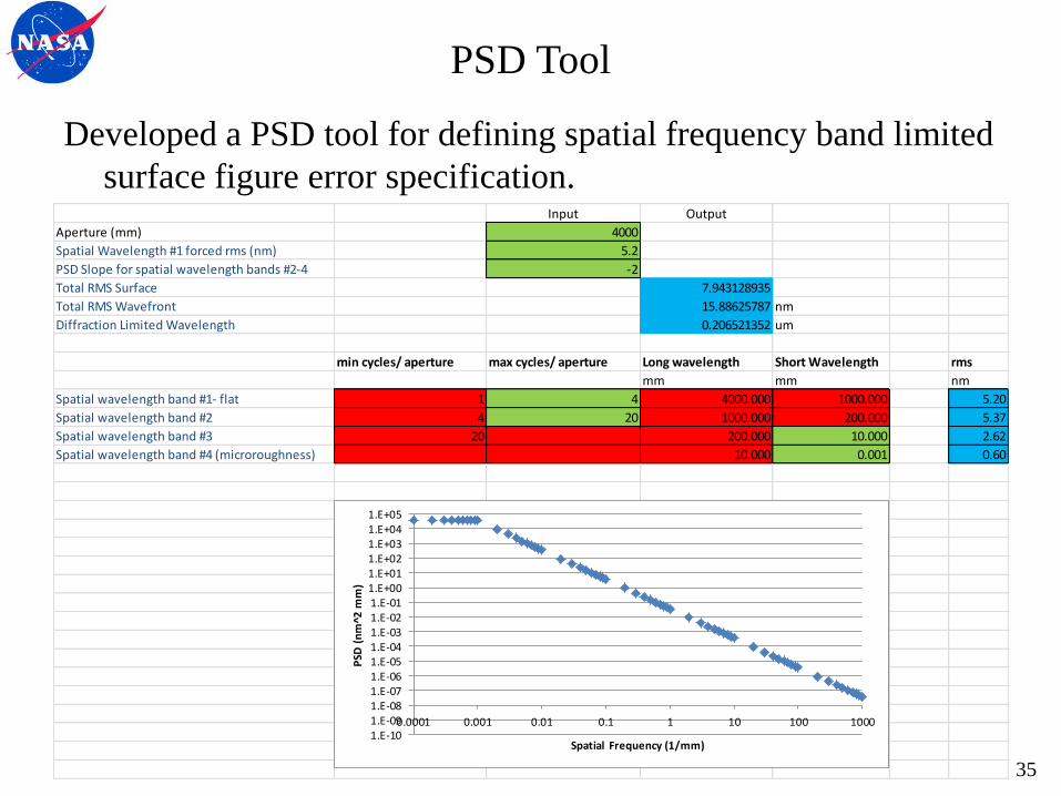
PSD Tool
Developed a PSD tool for defining spatial frequency band limited
surface figure error specification. Input Output
Aperture (mm) 4000
Spatial Wavelength #1 forced rms (nm) 5.2
PSD Slope for spatial wavelength bands #2-4 -2
Total RMS Surface 7.943128935
Total RMS Wavefront 15.88625787 nm
Diffraction Limited Wavelength 0.206521352 um
min cycles/ aperture max cycles/ aperture Long wavelength Short Wavelength rms
mm mm nm
Spatial wavelength band #1- flat 1 4 4000.000 1000.000 5.20
Spatial wavelength band #2 4 20 1000.000 200.000 5.37
Spatial wavelength band #3 20 200.000 10.000 2.62
Spatial wavelength band #4 (microroughness) 10.000 0.001 0.60
1.E-101.E-091.E-081.E-071.E-061.E-051.E-041.E-031.E-021.E-011.E+001.E+011.E+021.E+031.E+041.E+05
0.0001 0.001 0.01 0.1 1 10 100 1000
PSD
(n
m^2
mm
)
Spatial Frequency (1/mm)
35
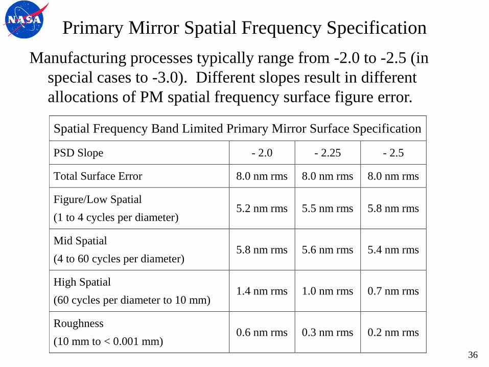
Primary Mirror Spatial Frequency Specification
Manufacturing processes typically range from -2.0 to -2.5 (in
special cases to -3.0). Different slopes result in different
allocations of PM spatial frequency surface figure error.
Spatial Frequency Band Limited Primary Mirror Surface Specification
PSD Slope - 2.0 - 2.25 - 2.5
Total Surface Error 8.0 nm rms 8.0 nm rms 8.0 nm rms
Figure/Low Spatial
(1 to 4 cycles per diameter) 5.2 nm rms 5.5 nm rms 5.8 nm rms
Mid Spatial
(4 to 60 cycles per diameter) 5.8 nm rms 5.6 nm rms 5.4 nm rms
High Spatial
(60 cycles per diameter to 10 mm) 1.4 nm rms 1.0 nm rms 0.7 nm rms
Roughness
(10 mm to < 0.001 mm) 0.6 nm rms 0.3 nm rms 0.2 nm rms
36
Wavefront Error Stability Specification
37
Primary Mirror Surface Figure Error Stability
Per Krist, once a 10-10 contrast dark hole has been created, the
corrected wavefront phase must be kept stable to within a few
picometers rms between science exposures to maintain the
instantaneous (not averaged over integration time) speckle
intensity to within 10-11 contrast.
Any drift in WFE can result in speckles which can produce a
false exoplanet measurement or mask a true signal.
WFE can vary with time due to the response of optics, structure
and mounts to mechanical and thermal stimuli. • Vibrations can be excited from reaction wheels, gyros, etc.
• Thermal drift can occur from slew changes relative to Sun
Krist, Trauger, Unwin and Traub, “End-to-end coronagraphic modeling including a low-order wavefront sensor”,
SPIE Vol. 8422, 844253, 2012; doi: 10.1117/12.927143
Lyon & Clampin, “Space telescope sensitivity and controls for exoplanet imaging”, Optical Engineering, Vol 51,
2012; 011002-2 38

Primary Mirror Surface Figure Error Stability
If the telescope system cannot be designed with sufficient
stability, then the WFE must be controlled actively.
If one assumes that DMs can ‘perfectly’ correct WFE drift, then
the Telescope must have a WFE drift less than the required
‘few’ picometers over the active control period.
Lyon and Clampin, “Space telescope sensitivity and controls for exoplanet imaging”, Optical Engineering, Vol
51, 2012; 011002-2 39
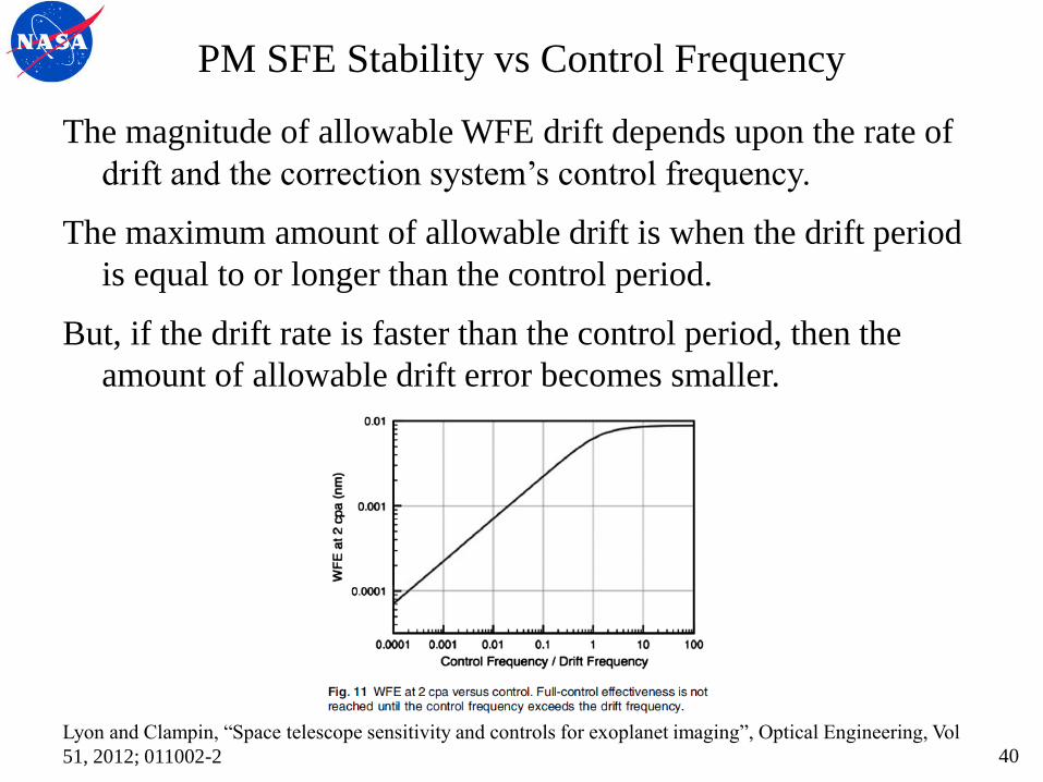
PM SFE Stability vs Control Frequency
The magnitude of allowable WFE drift depends upon the rate of
drift and the correction system’s control frequency.
The maximum amount of allowable drift is when the drift period
is equal to or longer than the control period.
But, if the drift rate is faster than the control period, then the
amount of allowable drift error becomes smaller.
Lyon and Clampin, “Space telescope sensitivity and controls for exoplanet imaging”, Optical Engineering, Vol
51, 2012; 011002-2 40

Controllability Period
Krist (Private Communication, 2013): wavefront changes can be
measured with accuracy of 5 – 8 pm rms for first 11 Zernikes in 60 –
120 sec on a 5th magnitude star in a 4 m telescope over a 500 – 600
nm pass band (reflection off the occulter). This accuracy scales
proportional to square root of exposure time or telescope area.
Lyon (Private Communication, 2013): 8 pm control takes ~64 sec for a
Vega 0th mag star and 500 – 600 nm pass band [108 photons/m2-sec-
nm produce 4.7 x 10⁵ electrons/DOF and sensing error ~ 0.00073
radians = 64 pm at λ= 550 nm]
Guyon (Private Communication, 2012): measuring a single sine wave
to 0.8 pm amplitude on a Magnitude V=5 star with an 8-m diameter
telescope and a 100 nm effective bandwidth takes 20 seconds.
[Measurement needs 1011 photons and V=5 star has 106 photons/m2-
sec-nm.] BUT, Controllability needs 3 to 10 Measurements, thus
stability period requirement is 10X measurement period. 41
Primary Mirror SFE Stability Specification
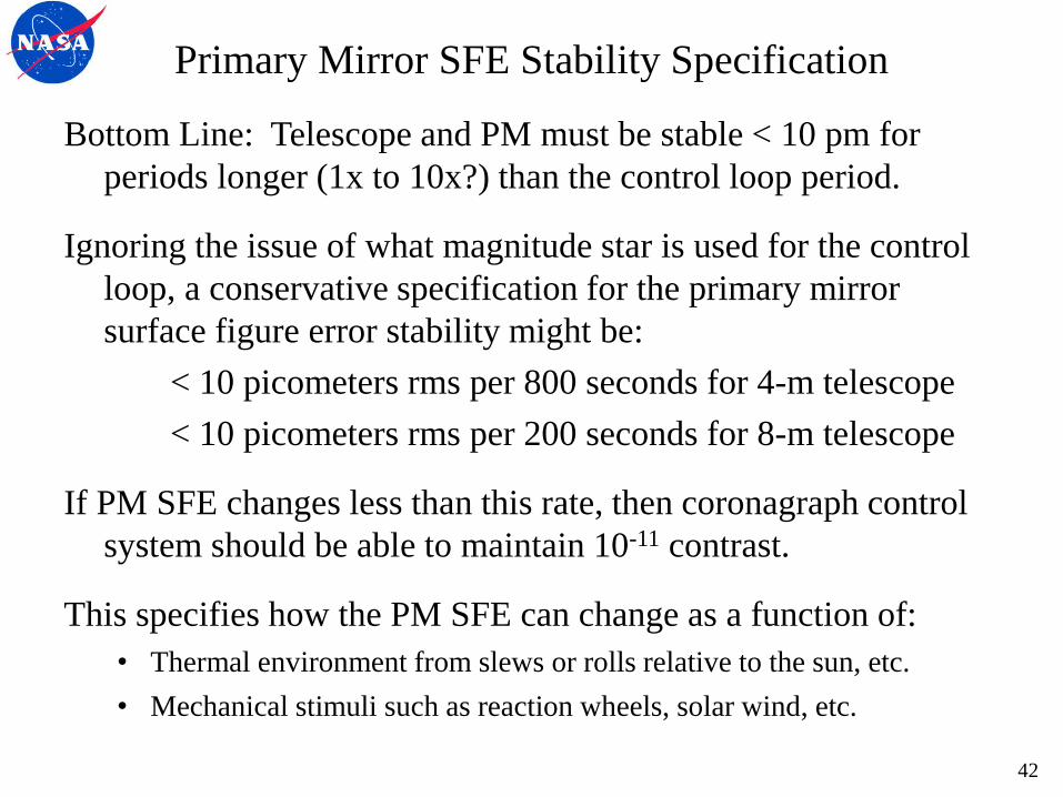
Bottom Line: Telescope and PM must be stable < 10 pm for
periods longer (1x to 10x?) than the control loop period.
Ignoring the issue of what magnitude star is used for the control
loop, a conservative specification for the primary mirror
surface figure error stability might be:
< 10 picometers rms per 800 seconds for 4-m telescope
< 10 picometers rms per 200 seconds for 8-m telescope
If PM SFE changes less than this rate, then coronagraph control
system should be able to maintain 10-11 contrast.
This specifies how the PM SFE can change as a function of:
• Thermal environment from slews or rolls relative to the sun, etc.
• Mechanical stimuli such as reaction wheels, solar wind, etc.
42
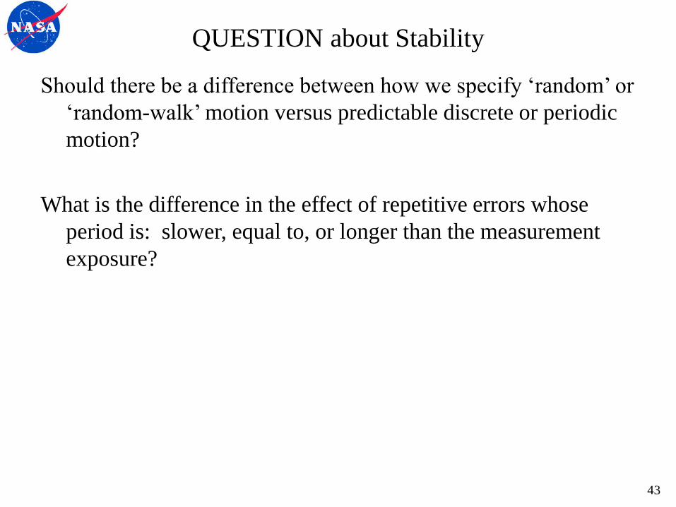
QUESTION about Stability
Should there be a difference between how we specify ‘random’ or
‘random-walk’ motion versus predictable discrete or periodic
motion?
What is the difference in the effect of repetitive errors whose
period is: slower, equal to, or longer than the measurement
exposure?
43

How sensitive is SFE to thermal environment changes from slews
and rotations?
How slowly or rapidly does the SFE change?
Is it better to have a rapid equalization or a very long time
constant?
Thermal inertia.
Same with sensitivity to mechanical disturbances.
44
Line of Sight Pointing Stability Specification
45
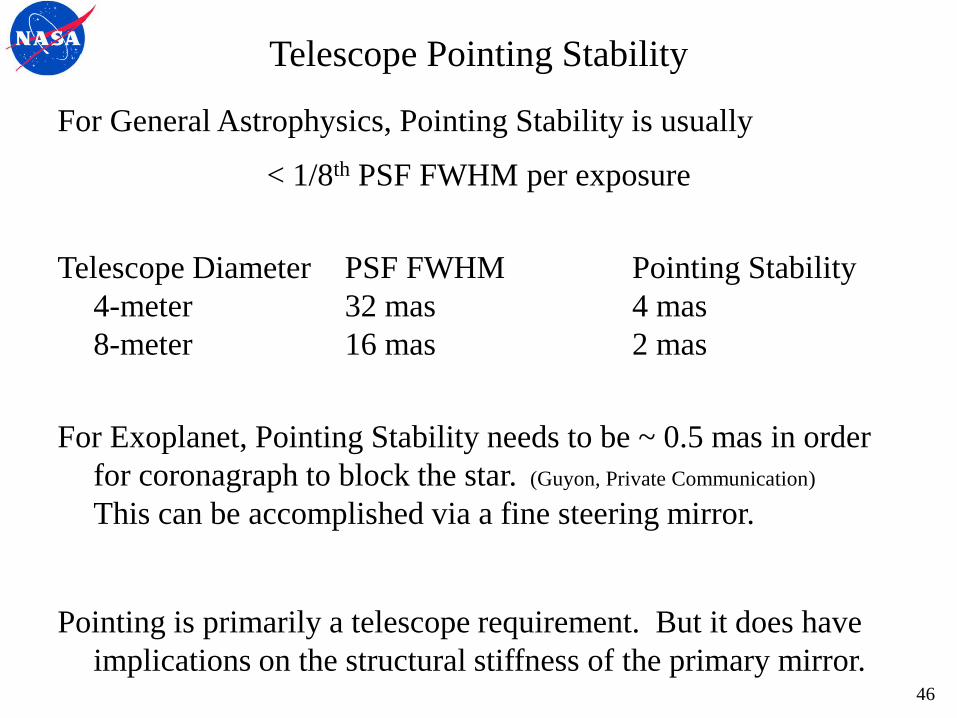
Telescope Pointing Stability
For General Astrophysics, Pointing Stability is usually
< 1/8th PSF FWHM per exposure
Telescope Diameter PSF FWHM Pointing Stability
4-meter 32 mas 4 mas
8-meter 16 mas 2 mas
For Exoplanet, Pointing Stability needs to be ~ 0.5 mas in order
for coronagraph to block the star. (Guyon, Private Communication)
This can be accomplished via a fine steering mirror.
Pointing is primarily a telescope requirement. But it does have
implications on the structural stiffness of the primary mirror.
46

Segmented Aperture
47

Monolithic vs Segmented Aperture
Engineering Specifications derived apply to Monolithic &
Segmented – Segmented must meet all specifications.
But segmented apertures have additional challenges:
• Segmentation Pattern results in secondary peaks
• Segmentation Gaps redistribute energy
• Rolled Edges redistribute energy
• Segment Co-Phasing Absolute Accuracy
• Segment Co-Phasing Stability
There are many different potential segmentation schemes,
ranging from hexagonal segments to pie segments to large
circular mirrors. The selection and analysis of potential
segmentation patterns is beyond the scope of this effort.
For this analysis, we assume hexagonal.
48

Hexagonally Segmented Aperture
49 Yaitskova, Dohlen and Dierickx, “Analytical study of diffraction effects in extremely large segmented telescopes”,
JOSA, Vol.20, No.8, Aug 2003.
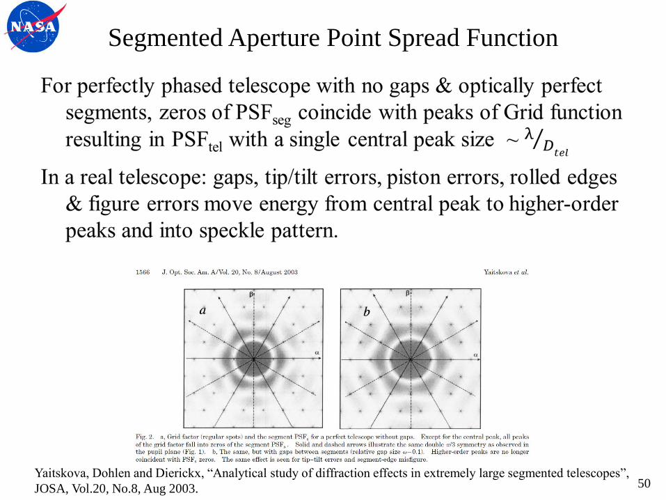
Segmented Aperture Point Spread Function
Yaitskova, Dohlen and Dierickx, “Analytical study of diffraction effects in extremely large segmented telescopes”,
JOSA, Vol.20, No.8, Aug 2003. 50

Segmentation Pattern vs. Dark Hole
Question: Is fewer large segments better or is many small better?
If segment relative position errors are static and correctable via a
segmented DM, then it should be possible to remove effects of
higher-order peaks.
If the goal is to produce a ‘dark hole’, should the segmentation
pattern be selected to keep higher-order peaks beyond the outer
working angle (OWA)?
For example, an aperture composed of many small segments (e.g.
32 segments per diameter in 16 rings) will have higher-order
peaks that are beyond the outer working angle (16λ/D).
51
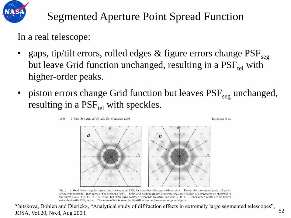
Segmented Aperture Point Spread Function
In a real telescope:
• gaps, tip/tilt errors, rolled edges & figure errors change PSFseg
but leave Grid function unchanged, resulting in a PSFtel with
higher-order peaks.
• piston errors change Grid function but leaves PSFseg unchanged,
resulting in a PSFtel with speckles.
Yaitskova, Dohlen and Dierickx, “Analytical study of diffraction effects in extremely large segmented telescopes”,
JOSA, Vol.20, No.8, Aug 2003. 52
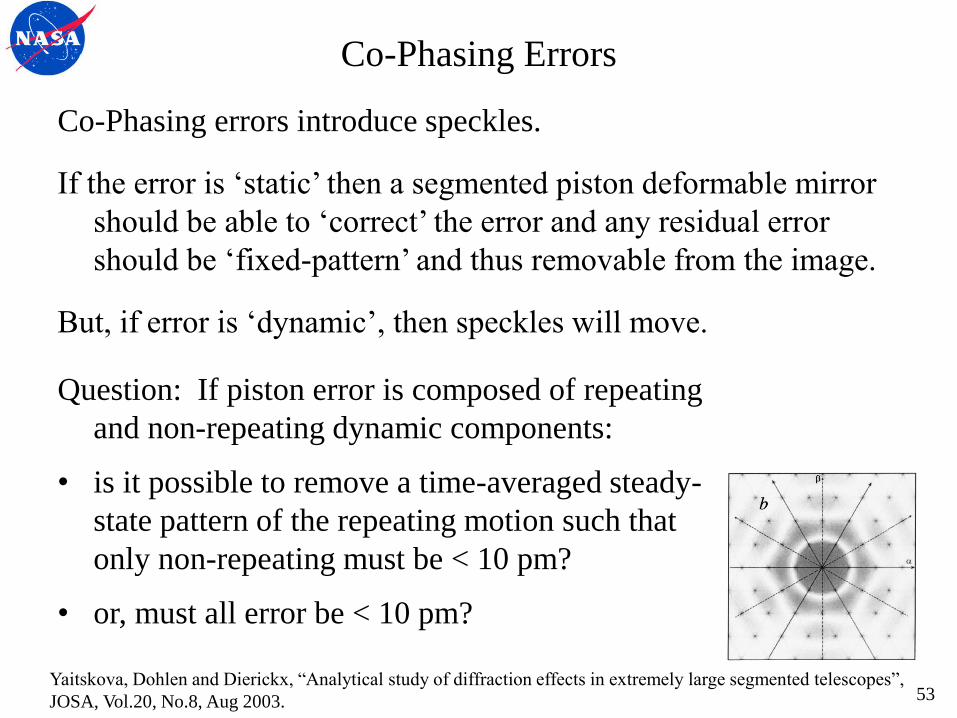
Co-Phasing Errors
Co-Phasing errors introduce speckles.
If the error is ‘static’ then a segmented piston deformable mirror
should be able to ‘correct’ the error and any residual error
should be ‘fixed-pattern’ and thus removable from the image.
But, if error is ‘dynamic’, then speckles will move.
53 Yaitskova, Dohlen and Dierickx, “Analytical study of diffraction effects in extremely large segmented telescopes”,
JOSA, Vol.20, No.8, Aug 2003.
Question: If piston error is composed of repeating
and non-repeating dynamic components:
• is it possible to remove a time-averaged steady-
state pattern of the repeating motion such that
only non-repeating must be < 10 pm?
• or, must all error be < 10 pm?
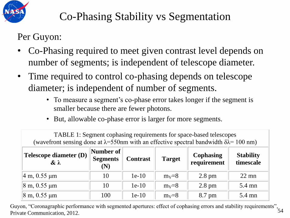
Co-Phasing Stability vs Segmentation
Per Guyon:
• Co-Phasing required to meet given contrast level depends on
number of segments; is independent of telescope diameter.
• Time required to control co-phasing depends on telescope
diameter; is independent of number of segments.
• To measure a segment’s co-phase error takes longer if the segment is
smaller because there are fewer photons.
• But, allowable co-phase error is larger for more segments.
54 Guyon, “Coronagraphic performance with segmented apertures: effect of cophasing errors and stability requirements”,
Private Communication, 2012.
TABLE 1: Segment cophasing requirements for space-based telescopes
(wavefront sensing done at λ=550nm with an effective spectral bandwidth δλ= 100 nm)
Telescope diameter (D)
& λ
Number of
Segments
(N)
Contrast Target Cophasing
requirement
Stability
timescale
4 m, 0.55 μm 10 1e-10 mV=8 2.8 pm 22 mn
8 m, 0.55 μm 10 1e-10 mV=8 2.8 pm 5.4 mn
8 m, 0.55 μm 100 1e-10 mV=8 8.7 pm 5.4 mn
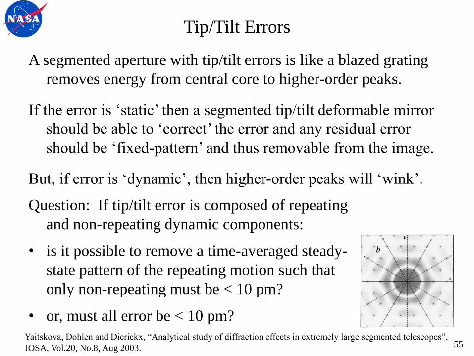
Tip/Tilt Errors
A segmented aperture with tip/tilt errors is like a blazed grating
removes energy from central core to higher-order peaks.
If the error is ‘static’ then a segmented tip/tilt deformable mirror
should be able to ‘correct’ the error and any residual error
should be ‘fixed-pattern’ and thus removable from the image.
But, if error is ‘dynamic’, then higher-order peaks will ‘wink’.
55 Yaitskova, Dohlen and Dierickx, “Analytical study of diffraction effects in extremely large segmented telescopes”,
JOSA, Vol.20, No.8, Aug 2003.
Question: If tip/tilt error is composed of repeating
and non-repeating dynamic components:
• is it possible to remove a time-averaged steady-
state pattern of the repeating motion such that
only non-repeating must be < 10 pm?
• or, must all error be < 10 pm?
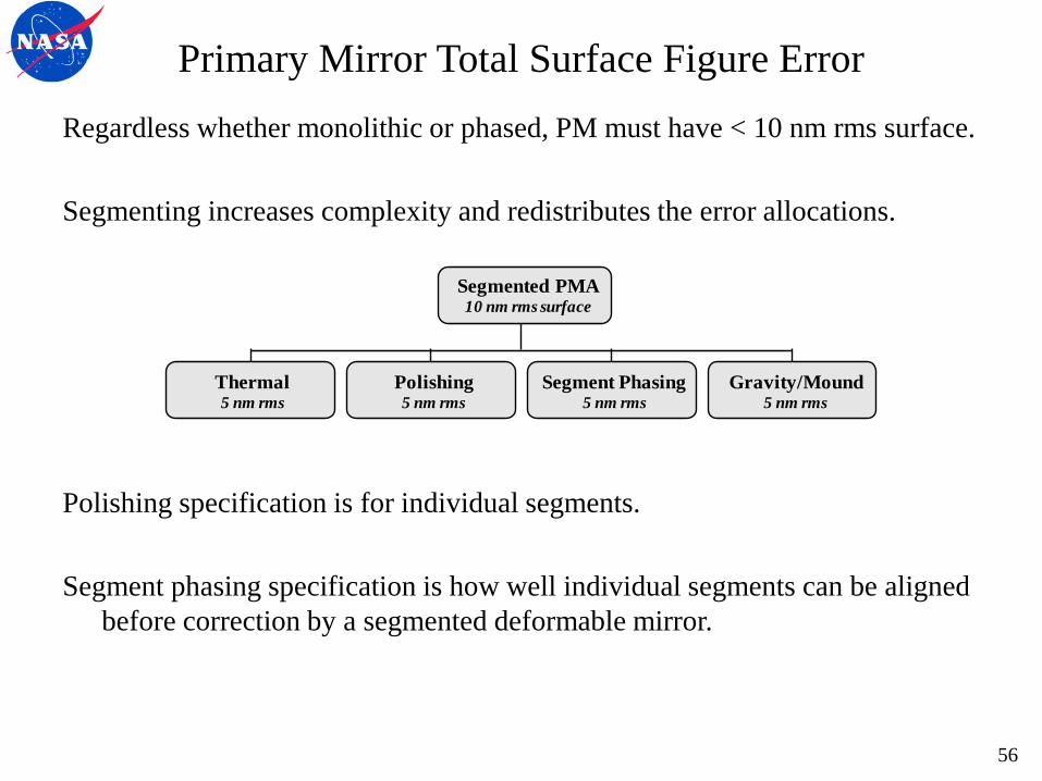
Primary Mirror Total Surface Figure Error
Regardless whether monolithic or phased, PM must have < 10 nm rms surface.
Segmenting increases complexity and redistributes the error allocations.
Polishing specification is for individual segments.
Segment phasing specification is how well individual segments can be aligned
before correction by a segmented deformable mirror.
56
Polishing5 nm rms
Gravity/Mound5 nm rms
Thermal5 nm rms
Segment Phasing5 nm rms
Segmented PMA10 nm rms surface

Segment Gaps and Edges
Gaps between segments and segment edge roll-off both effect the
segment point spread function and redistributes energy from
the central core to the to higher-order peaks.
Effect is complicated by variations in gap spacing & edge roll-off
These errors cannot be corrected via a deformable mirror.
But, they are ‘static’ and their effect can be removed from image.
57
Yaitskova, Dohlen and Dierickx, “Analytical study of diffraction effects in extremely
large segmented telescopes”, JOSA, Vol.20, No.8, Aug 2003.
QED - NASA SBIR 03-S2.05-7100; Zeeko - NASA SBIR 04-S2.04-9574
Segment to Segment Gap distance is determined
by geometry and ‘non-interference’ issues.
Segment Edge Roll-Off effects collecting aperture
& Strehl. A good specification is < 5 mm
(JWST is < 7 mm; QED & Zeeko SOA is ~ 2 mm).
Summary Science Driven Specifications
58

Telescope Performance Requirements
Science is enabled by the performance of the entire Observatory:
Telescope and Science Instruments.
Telescope Specifications depend upon the Science Instrument.
Telescope Specifications have been defined for 3 cases: 4 meter Telescope with an Internal Masking Coronagraph
8 meter Telescope with an Internal Masking Coronagraph
8 meter Telescope with an External Occulter
WFE Specification is before correction by a Deformable Mirror
WFE/EE Stability and MSF WFE are the stressing specifications
AMTD has not studied the specifications for a Visible Nulling
Coronagraph or phase type coronagraph.
59

4m Telescope Requirements for use with Coronagraph
On-axis Monolithic 4-m Telescope with Coronagraph
Performance Parameter Specification Comments
Maximum total system rms WFE 38 nm Diffraction limit (80% Strehl at 500 nm)
Encircled Energy Fraction (EEF) 80% within 32 mas
at 500 nm
HST spec, modified to larger aperture
and slightly bluer wavelength Vary < 5% across 8 arcmin FOV
EEF stability <2% JWST
Telescope WFE stability < 10 pm per 800 sec
PM rms surface error 5 - 10 nm
Pointing stability (jitter) ~4 mas scaled from HST Guyon: ~ 0.5 mas determined by stellar
angular diameter.
Mid-frequency WFE < 4 nm
60

8m Telescope Requirements for use with Coronagraph
On-axis Monolithic 8-m Telescope with Coronagraph
Performance Parameter Specification Comments
Maximum total system rms WFE 38 nm Diffraction limit (80% Strehl at 500 nm)
Encircled Energy Fraction (EEF) 80% within 16 mas
at 500 nm
HST spec, modified to larger aperture
and slightly bluer wavelength Vary < 5% across 4 arcmin FOV
EEF stability <2% JWST
Telescope WFE stability < 10 pm per 200 sec
PM rms surface error 5 - 10 nm
Pointing stability (jitter) ~2 mas scaled from HST Guyon: ~ 0.5 mas determined by stellar
angular diameter.
Mid-frequency WFE < 4 nm
61

8m Telescope Requirements for use with Coronagraph
On-axis Segmented 8-m Telescope with Coronagraph
Performance Parameter Specification Comments
Maximum total system rms WFE 38 nm Diffraction limit (80% Strehl at 500 nm)
Encircled Energy Fraction (EEF) 80% within 16 mas at
500 nm
HST spec, modified to larger aperture &
bluer wavelength
Vary < 5% across 4 arcmin FOV
EEF stability <2% JWST
WFE stability < 10 pm per 200 sec
Segment gap stability TBD Soummer, McIntosh 2013
Number and Size of Segments TBD
(1 – 2m, 36 max) Soummer 2013
Segment edge roll-off stability TBD Sivaramakrishnan 2013
Segment co-phasing stability 4 to 6 pm per 300 secs Depends on number of segments
Pointing stability (jitter) ~2 mas
scaled from HST
Guyon, ~ 0.5 mas floor determined by
stellar angular diameter.
62
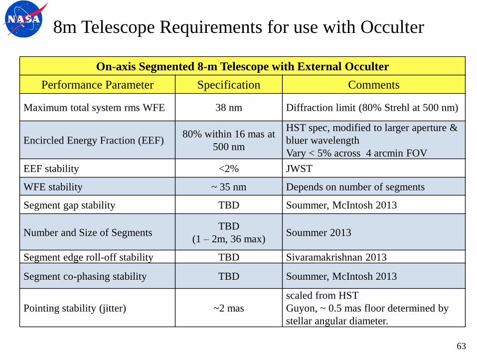
8m Telescope Requirements for use with Occulter
On-axis Segmented 8-m Telescope with External Occulter
Performance Parameter Specification Comments
Maximum total system rms WFE 38 nm Diffraction limit (80% Strehl at 500 nm)
Encircled Energy Fraction (EEF) 80% within 16 mas at
500 nm
HST spec, modified to larger aperture &
bluer wavelength
Vary < 5% across 4 arcmin FOV
EEF stability <2% JWST
WFE stability ~ 35 nm Depends on number of segments
Segment gap stability TBD Soummer, McIntosh 2013
Number and Size of Segments TBD
(1 – 2m, 36 max) Soummer 2013
Segment edge roll-off stability TBD Sivaramakrishnan 2013
Segment co-phasing stability TBD Soummer, McIntosh 2013
Pointing stability (jitter) ~2 mas
scaled from HST
Guyon, ~ 0.5 mas floor determined by
stellar angular diameter.
63

Implementation Constraints
64
Representative Missions
Four ‘representative’ mission architectures achieve Science:
• 4-m monolith launched on an EELV,
• 8-m monolith on a HLLV,
• 8-m segmented on an EELV
• 16-m segmented on a HLLV.
The key difference between launch vehicles is up-mass
EELV can place 6.5 mt to Sun-Earth L2
HLLV is projected to place 40 to 60 mt to Sun-Earth L2
The other difference is launch fairing diameter
EELV has 5 meter fairing
HLLV is projected to have a 8 to 10 meter fairing
65
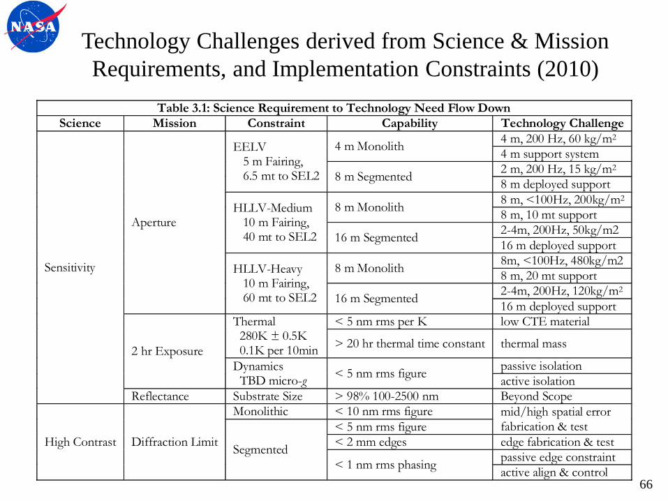
Technology Challenges derived from Science & Mission
Requirements, and Implementation Constraints (2010)
Table 3.1: Science Requirement to Technology Need Flow Down
Science Mission Constraint Capability Technology Challenge
Sensitivity
Aperture
EELV 5 m Fairing, 6.5 mt to SEL2
4 m Monolith 4 m, 200 Hz, 60 kg/m2
4 m support system
8 m Segmented 2 m, 200 Hz, 15 kg/m2
8 m deployed support
HLLV-Medium 10 m Fairing, 40 mt to SEL2
8 m Monolith 8 m, <100Hz, 200kg/m2
8 m, 10 mt support
16 m Segmented 2-4m, 200Hz, 50kg/m2
16 m deployed support
HLLV-Heavy 10 m Fairing, 60 mt to SEL2
8 m Monolith 8m, <100Hz, 480kg/m2
8 m, 20 mt support
16 m Segmented 2-4m, 200Hz, 120kg/m2
16 m deployed support
2 hr Exposure
Thermal 280K ± 0.5K 0.1K per 10min
< 5 nm rms per K low CTE material
> 20 hr thermal time constant thermal mass
Dynamics TBD micro-g
< 5 nm rms figure passive isolation
active isolation
Reflectance Substrate Size > 98% 100-2500 nm Beyond Scope
High Contrast Diffraction Limit
Monolithic < 10 nm rms figure mid/high spatial error fabrication & test
Segmented
< 5 nm rms figure
< 2 mm edges edge fabrication & test
< 1 nm rms phasing passive edge constraint
active align & control
66

Space Launch System (SLS)
Space Launch System (SLS) Cargo Launch Vehicle specifications
Preliminary Design Concept
8.3 m dia x 18 m tall fairing
70 to 100 mt to LEO
consistent with HLLV Medium
Enhanced Design Concept
10.0 m dia x 30 m tall fairing
130 mt to LEO
consistent with HLLV Heavy
HLLV Medium could launch an 8-m segmented telescope whose
mirror segments have an areal density of 60 kg/m2.
67 Stahl, H. Philip, Phil Sumrall, and Randall Hopkins, “Ares V launch vehicle: an enabling capability for future
space science missions”, Acta Astronautica, Elsevier Ltd., 2009, doi:10.1016/j.actaastro.2008.12.017

Mass
Mass is the most important factor in the ability of a mirror to
survive launch and meet its required on-orbit performance.
More massive mirrors are
stiffer and thus easier and less expensive to fabricate;
more mechanically and thermally stable.
68
Primary Mirror Mass Allocation
Given that JWST is being designed to a 6500 kg mass budget, we
are using JWST to define the EELV telescope mass budget: Optical Telescope Assembly < 2500 kg
Primary Mirror Assembly < 1750 kg
Primary Mirror Substrate < 750 kg
This places areal density constraints of: Aperture PMA PM
4 meter 145 kg 62.5 kg
8 meter 35 kg 15 kg
An HLLV would allow a much larger mass budget Optical Telescope Assembly < 20,000 to 30,000 kg
Primary Mirror Assembly < 15,000 to 25,000 kg
Primary Mirror Substrate < 10,000 to 20,000 kg
69
Launch Loads
Primary mirror assembly for any potential mission must survive
launch without degrading its on-orbit performance.
Launch environment for SLS is unknown.
We are specifying to a representative EELV (Delta-IV Heavy)
Launch Loads & Coupled Loads
Vibro-Acoustic
70

Combined Steady and Dynamic Acceleration
Delta-IV Heavy axial and lateral G loads applied to spacecraft
model (mass at center of gravity) envelops spacecraft/launch
vehicle interface loads.
For a minimum payload mass of 6577 kg, (from Coupled Mode
Analysis), payload minimum:
axial frequency = 30 Hz; lateral frequency = 8 Hz
71 Delta IV Payload Planners Guide, United Launch Alliance, Sept 2007
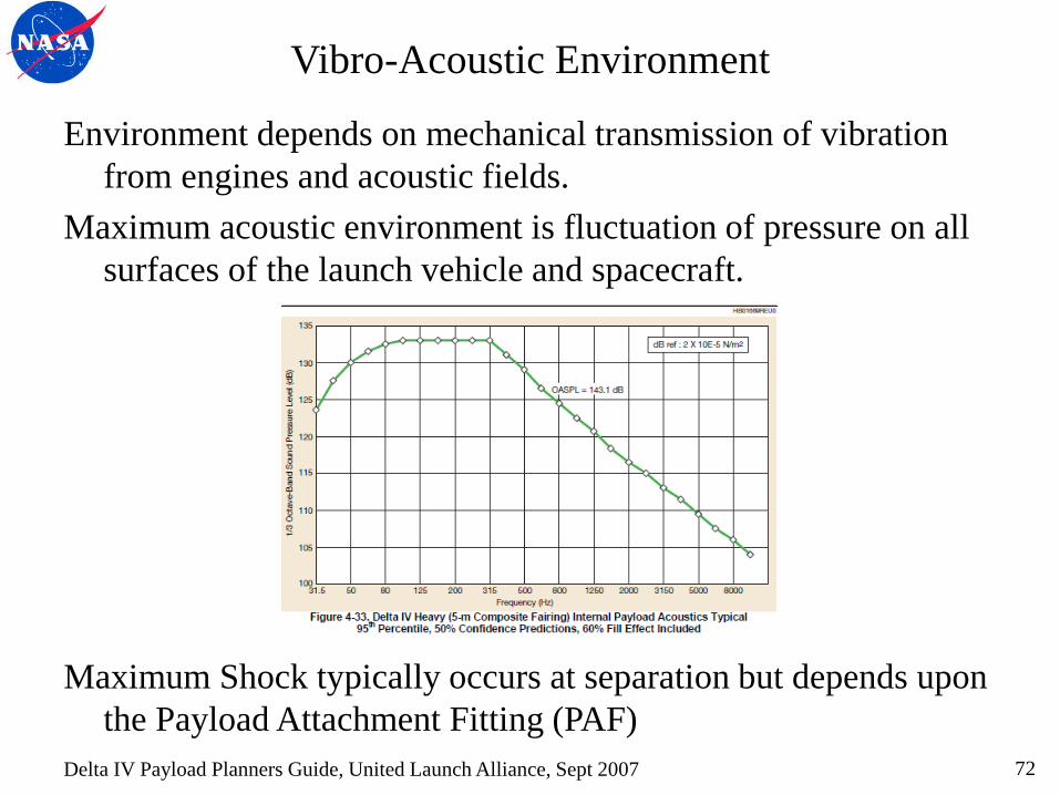
Vibro-Acoustic Environment
Environment depends on mechanical transmission of vibration
from engines and acoustic fields.
Maximum acoustic environment is fluctuation of pressure on all
surfaces of the launch vehicle and spacecraft.
Maximum Shock typically occurs at separation but depends upon
the Payload Attachment Fitting (PAF)
72 Delta IV Payload Planners Guide, United Launch Alliance, Sept 2007

Conclusions
73
Conclusion
AMTD is using a Science Driven Systems Engineering approach
to develop Engineering Specifications based on Science
Measurement Requirements and Implementation Constraints.
Science requirements meet the needs of both Exoplanet and
General Astrophysics science.
Engineering Specifications are guiding our effort to mature to
TRL-6 the critical technologies needed to produce 4-m or
larger flight-qualified UVOIR mirrors by 2018 so that a viable
mission can be considered by the 2020 Decadal Review.
Engineering Specification is a ‘living’ document.
74

Bibliography
Delta IV Payload Planners Guide, United Launch Alliance, Sept 2007
Harvey, Lewotsky and Kotha, “Effects of surface scatter on the optical performance of x-ray synchrotron beam-line mirrors”, Applied Optics, Vol. 34, No. 16, pp.3024, 1995.
Guyon, Private Communication 2012
Guyon, “Coronagraphic performance with segmented apertures: effect of cophasing errors and stability requirements”, Private Communication, 2012.
Krist, Private Communication 2013
Krist, Trauger, Unwin and Traub, “End-to-end coronagraphic modeling including a low-order wavefront sensor”, SPIE Vol. 8422, 844253, 2012; doi: 10.1117/12.927143
Lyon, Private Communication 2013
Lyon and Clampin, “Space telescope sensitivity and controls for exoplanet imaging”, Optical Engineering, Vol 51, 2012; 011002-2
Mountain, M., van der Marel, R., Soummer, R., et al. Submission to NRC ASTRO2010 Decadal Survey, 2009
QED - NASA SBIR 03-S2.05-7100.
Shaklan, Green and Palacios, “TPFC Optical Surface Requirements”, SPIE 626511-12, 2006.
Shaklan & Green, “Reflectivity and optical surface height requirements in a coronagraph”, Applied Optics, 2006
Stahl, H. Philip, Phil Sumrall, and Randall Hopkins, “Ares V launch vehicle: an enabling capability for future space science missions”, Acta Astronautica, Elsevier Ltd., 2009, doi:10.1016/j.actaastro.2008.12.017
Yaitskova, Dohlen and Dierickx, “Analytical study of diffraction effects in extremely large segmented telescopes”, JOSA, Vol.20, No.8, Aug 2003.
Zeeko - NASA SBIR 04-S2.04-9574.
75

BACKUP
76
Harvey, Lewotsky and Kotha, “Effects of surface scatter on the optical performance of x-ray synchrotron beam-line mirrors”, Applied Optics, Vol. 34,
No. 16, pp.3024, 1995.
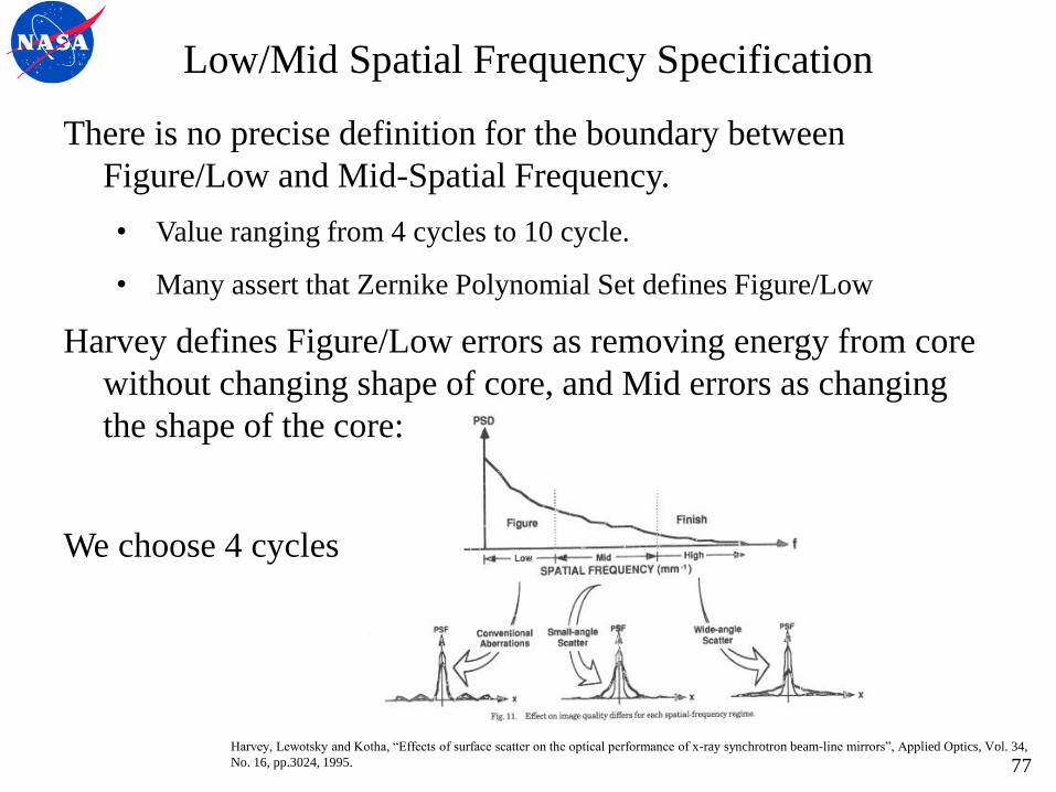
Low/Mid Spatial Frequency Specification
There is no precise definition for the boundary between
Figure/Low and Mid-Spatial Frequency.
• Value ranging from 4 cycles to 10 cycle.
• Many assert that Zernike Polynomial Set defines Figure/Low
Harvey defines Figure/Low errors as removing energy from core
without changing shape of core, and Mid errors as changing
the shape of the core:
We choose 4 cycles
77

Mid/High Spatial Frequency Specification
Just as there is no definitive Low/Mid, there is no definitive
Mid/High Spatial Frequency Boundary.
Harvey would define it as the spatial frequency at which energy
starts being distributed broadly across the image.
Noll (“Effect ofMid- and High-Spatial Frequencies on Optical Performance”, Optical
Engineering, Vol. 18, No. 2, pp.137, 1979) defines it as the spatial
frequency which scatters energy beyond 16 Airy Rings.
Wetherell (“The Calculation of Image Quality”, Applied Optics and Optical
Engineering, Vol. VIII, Academic Press, 1980) defines it as the spatial
frequency which scatters energy beyond 10 Airy Rings.
78
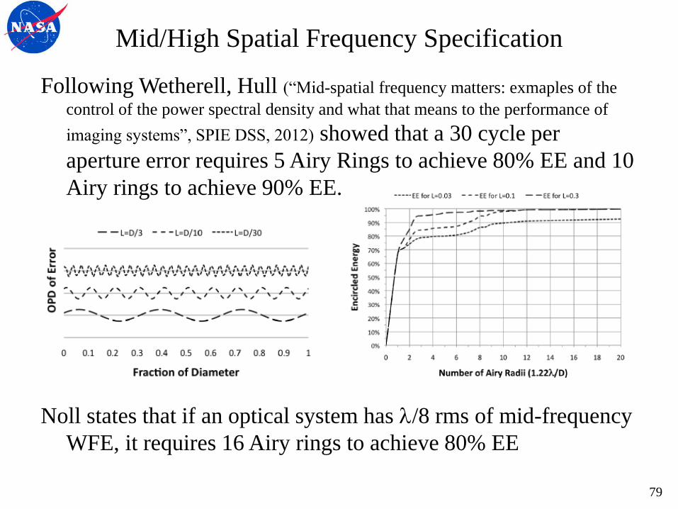
Following Wetherell, Hull (“Mid-spatial frequency matters: exmaples of the
control of the power spectral density and what that means to the performance of
imaging systems”, SPIE DSS, 2012) showed that a 30 cycle per
aperture error requires 5 Airy Rings to achieve 80% EE and 10
Airy rings to achieve 90% EE.
Noll states that if an optical system has /8 rms of mid-frequency
WFE, it requires 16 Airy rings to achieve 80% EE
Mid/High Spatial Frequency Specification
79
Ultraviolet Capability
Science Applications are somewhat wavelength dependent:
90 to 120 nm High Resolution Spectroscopy
120 to 150 nm Imaging and Spectroscopy
> 150 nm Imaging
Far-UV high resolution spectroscopy PSF FWHM Specification
Requirement 200 mas at 150 nm
Goal 100 mas at 100 nm
This, as well as Exo-planet requirement for a compact PSF,
places constraints on Telescope Mid-Spatial Frequency error.
80

Mid/High Spatial Frequency Specification
Far-UV High-Resolution Spectroscopy desires 50% to 80% EE
for 100 to 200 mas.
4 m Telescope can achieve this in 4 to 5 Airy rings.
Diffraction limited at 500 nm results in an Airy Disc
Airy Disc /D 4 m 8 m
1st min 1.22 32 mas 16 mas
2nd min 2.23 58 mas 29 mas
3rd min 3.24 85 mas 42 mas
4th min 4.24 111 mas 56 mas
5th min 5.24 137 mas 69 mas
6th min 6.24 164 mas 82 mas
7th min 7.25 190 mas 95 mas
8th min 8.25 216 mas 108 mas
9th min 9.25 243 mas 121 mas
10th min 10.25 269 mas 134 mas
From Wetherell, this implies Mid/High boundary of 30 cycles
81
Related Documents