LAB MANUAL ENGINEERING SCIENCE LAB - I&II PHYSICS (2007)

Welcome message from author
This document is posted to help you gain knowledge. Please leave a comment to let me know what you think about it! Share it to your friends and learn new things together.
Transcript

LAB MANUAL
ENGINEERING SCIENCE LAB - I&II
PHYSICS (2007)
ENGINEERING SCIENCE LAB - I&II ( PHYSICS) REVISION-2015
MA’DIN POLYTECHNIC COLLEGE, MLAPPURAM 1
SYLLABUS
On completion of the course the student will be able to:
1. To measure volume of a cylinder using vernier calipers.
2. To measure volume of a wire using screw gauge.
3. To determine focal length of a convex lens by displacement method.
4. To determine the velocity of sound in air at room temperature using resonance column.
5. To determine spring constant using Hooke’s law..
6. To determine acceleration due to gravity using simple pendulum.
7. To verify law of resistances.
8. To determine specific resistance of material using Meter Bridge.
9. To determine Internal Resistance of a Primary Cell using Potentiometer.
10. To plot characteristics of photoelectric cell (photoelectric current vs. intensity of light
and voltage applied)
11. To determine the mass of the given body using moment bar.
12. To determine the mass of a body by parallelogram method and by Lami’s theorem.
13. To verify Ohm’s law and to determine the resistance of the given wire.
14.To determine the coefficient of viscosity of a highly viscous liquid.
15.To determine the relative density using U-tube apparutus
MA'DIN POLYTECHNIC COLLEGE
ENGINEERING PHYSICS LAB
MA’DIN POLYTECHNIC COLLEGE, MALAPPURAM 2
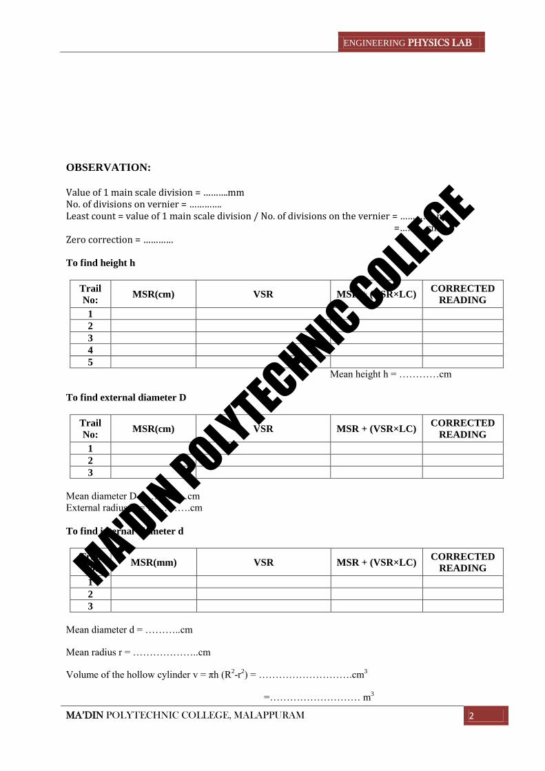
OBSERVATION:
Value of 1 main scale division = ……….mm No. of divisions on vernier = …………. Least count = value of 1 main scale division / No. of divisions on the vernier = ………….. mm =…….….cm Zero correction = ………… To find height h
Trail
No: MSR(cm) VSR MSR + (VSR×LC)
CORRECTED
READING
1
2
3
4
5
Mean height h = …………cm
To find external diameter D
Trail
No: MSR(cm) VSR MSR + (VSR×LC)
CORRECTED
READING
1
2
3
Mean diameter D = …………cm
External radius R = ………….cm
To find internal diameter d
Trail
No: MSR(mm) VSR MSR + (VSR×LC)
CORRECTED
READING
1
2
3
Mean diameter d = ………..cm
Mean radius r = ………………..cm
Volume of the hollow cylinder v = πh (R2-r
2) = ……………………….cm
3
=……………………… m3
MA'DIN POLYTECHNIC COLLEGE
ENGINEERING PHYSICS LAB
MA’DIN POLYTECHNIC COLLEGE, MALAPPURAM 3
Expt. No: 01
Date:
VERNIER CALIPERS
AIM:
To determine the volume of the given hollow cylinder.
APPARATUS:
Vernier calipers, hollow cylinder.
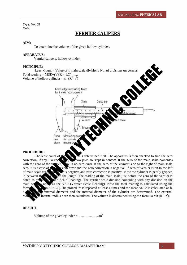
PRINCIPLE:
Least Count = Value of 1 main scale division / No. of divisions on vernier.
Total reading = MSR+(VSR × LC)……
Volume of hollow cylinder = πh (R2- r
2)
PROCEDURE:
The least count of the apparatus is determined first. The apparatus is then checked to find the zero
correction, if any. To check this, the two jaws are kept in contact. If the zero of the main scale coincides
with the zero of the vernier, there is no zero error. If the zero of the vernier is on to the right of main scale
zero, it is a case of positive zero error and the zero correction is negative, if zero of vernier is on to the left
of main scale zero, zero error is negative and zero correction is positive. Now the cylinder is gently gripped
in between the jaws to find the length. The reading of the main scale just before the zero of the vernier is
noted as the MSR (Main Scale Reading). The vernier scale division coinciding with any division on the
main scale is noted as the VSR (Vernier Scale Reading). Now the total reading is calculated using the
formula (MSR+ VSR×LC).The procedure is repeated at least 4 times and the mean value is calculated as h.
Similarly, the external diameter and the internal diameter of the cylinder are determined. The external
radius R and internal radius r are then calculated. The volume is determined using the formula π h (R2- r
2).
RESULT:
Volume of the given cylinder = ………………m3
MA'DIN POLYTECHNIC COLLEGE
ENGINEERING PHYSICS LAB
MA’DIN POLYTECHNIC COLLEGE, MALAPPURAM 4
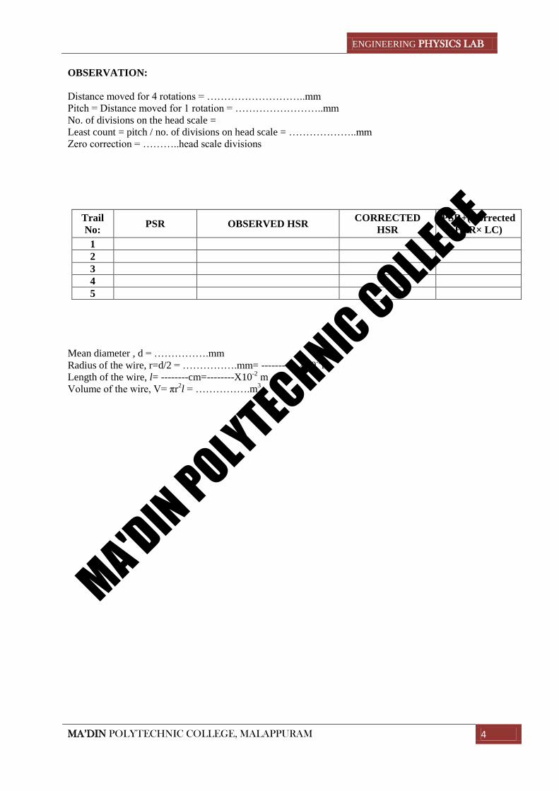
OBSERVATION:
Distance moved for 4 rotations = ………………………..mm
Pitch = Distance moved for 1 rotation = ……………………..mm
No. of divisions on the head scale =
Least count = pitch / no. of divisions on head scale = ………………..mm
Zero correction = ………..head scale divisions
Trail
No: PSR OBSERVED HSR
CORRECTED
HSR
PSR+(Corrected
HSR× LC)
1
2
3
4
5
Mean diameter , d = …………….mm
Radius of the wire, r=d/2 = …………….mm= ---------- X10-3
m
Length of the wire, l= --------cm=--------X10-2
m
Volume of the wire, V= πr2l = …………….m
3
MA'DIN POLYTECHNIC COLLEGE
ENGINEERING PHYSICS LAB
MA’DIN POLYTECHNIC COLLEGE, MALAPPURAM 5
Expt. No: 02
Date:
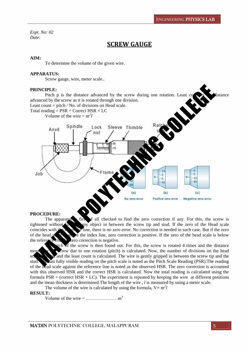
SCREW GAUGE
AIM:
To determine the volume of the given wire.
APPARATUS:
Screw gauge, wire, meter scale..
PRINCIPLE:
Pitch p is the distance advanced by the screw during one rotation. Least count is the distance
advanced by the screw as it is rotated through one division.
Least count = pitch / No. of divisions on Head scale.
Total reading = PSR + Correct HSR × LC
Volume of the wire = πr2l
PROCEDURE:
The apparatus is first of all checked to find the zero correction if any. For this, the screw is
tightened without keeping any object in between the screw tip and stud. If the zero of the Head scale
coincides with the reference line, there is no zero error. No correction is needed in such case. But if the zero
of the head scale is above the index line, zero correction is positive. If the zero of the head scale is below
the reference line the zero correction is negative.
The pitch of the screw is then found out. For this, the screw is rotated 4 times and the distance
moved by the screw due to one rotation (pitch) is calculated. Now, the number of divisions on the head
scale is noted and the least count is calculated. The wire is gently gripped in between the screw tip and the
stud. The last fully visible reading on the pitch scale is noted as the Pitch Scale Reading (PSR).The reading
of the head scale against the reference line is noted as the observed HSR. The zero correction is accounted
with this observed HSR and the correct HSR is calculated. Now the total reading is calculated using the
formula PSR + (correct HSR × LC). The experiment is repeated by keeping the wire at different positions
and the mean thickness is determined.The length of the wire , l is measured by using a meter scale.
The volume of the wire is calculated by using the formula, V= πr2l
RESULT:
Volume of the wire = …………………m3
MA'DIN POLYTECHNIC COLLEGE
ENGINEERING PHYSICS LAB
MA’DIN POLYTECHNIC COLLEGE, MALAPPURAM 6
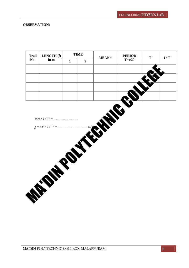
OBSERVATION:
Trail
No:
LENGTH (l)
in m
TIME MEAN t
PERIOD
T=t/20 T
2 l / T
2
1 2
Mean l / T2 = …………………
g = 4π2× l / T
2 = ……………………. m/s2
MA'DIN POLYTECHNIC COLLEGE
ENGINEERING PHYSICS LAB
MA’DIN POLYTECHNIC COLLEGE, MALAPPURAM 7
Expt. No: 03
Date:
SIMPLE PENDULUM AIMS:
1. To determine the value of acceleration due to gravity (g).
2. To determine the length of the seconds pendulum.
APPARATUS:
Simple pendulum, stop watch.
PRINCIPLE:
Acceleration due to gravity g = 4π2× l/T
2
A seconds pendulum is a simple pendulum having period of 2 seconds.
PROCEDURE:
The pendulum is set for a length 0.6m. (Length if the pendulum is the distance between the point of
suspension and the centre of gravity of the bob). The time for 20 oscillations is noted and the period is
calculated. This is repeated and the mean value of period is taken. The experiment is repeated for lengths
0.7m, 0.8m, 0.9m and 1m and in each case the value of l/T2 is used to determine g.
A graph is plotted with length along the X-axis and T2 along the Y-axis. A straight line graph is
drawn including maximum number of points. From the graph determine the value of length corresponding
to T2 equal to 4.
RESULTS:
1. Acceleration due to gravity g = …………………….. m/s2
2. Length of seconds pendulum = …………………… m.
MA'DIN POLYTECHNIC COLLEGE

ENGINEERING PHYSICS LAB
MA’DIN POLYTECHNIC COLLEGE, MALAPPURAM 8
OBSERVATION:
No:
Mass
suspended
in Kg
(M)
Pointer reading Extension in
m
(l)
Load=Mg
K=Mg/l
Loading Unloading Mean
Mean k = ----------N/m.
MA'DIN POLYTECHNIC COLLEGE
ENGINEERING PHYSICS LAB
MA’DIN POLYTECHNIC COLLEGE, MALAPPURAM 9
Expt. No:04
Date:
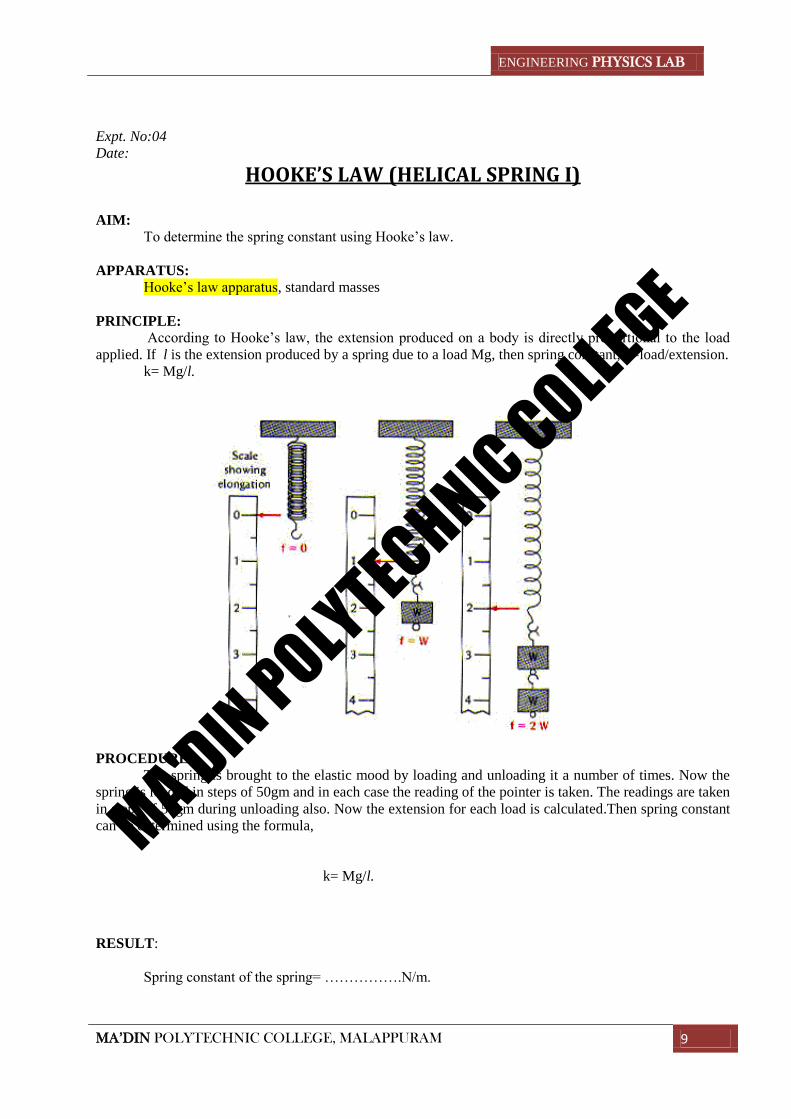
HOOKE’S LAW (HELICAL SPRING I)
AIM:
To determine the spring constant using Hooke’s law.
APPARATUS:
Hooke’s law apparatus, standard masses
PRINCIPLE:
According to Hooke’s law, the extension produced on a body is directly proportional to the load
applied. If l is the extension produced by a spring due to a load Mg, then spring constant, k=load/extension.
k= Mg/l.
PROCEDURE:
The spring is brought to the elastic mood by loading and unloading it a number of times. Now the
spring is loaded in steps of 50gm and in each case the reading of the pointer is taken. The readings are taken
in steps of 50gm during unloading also. Now the extension for each load is calculated.Then spring constant
can be determined using the formula,
k= Mg/l.
RESULT:
Spring constant of the spring= …………….N/m.
MA'DIN POLYTECHNIC COLLEGE
ENGINEERING PHYSICS LAB
MA’DIN POLYTECHNIC COLLEGE, MALAPPURAM 10
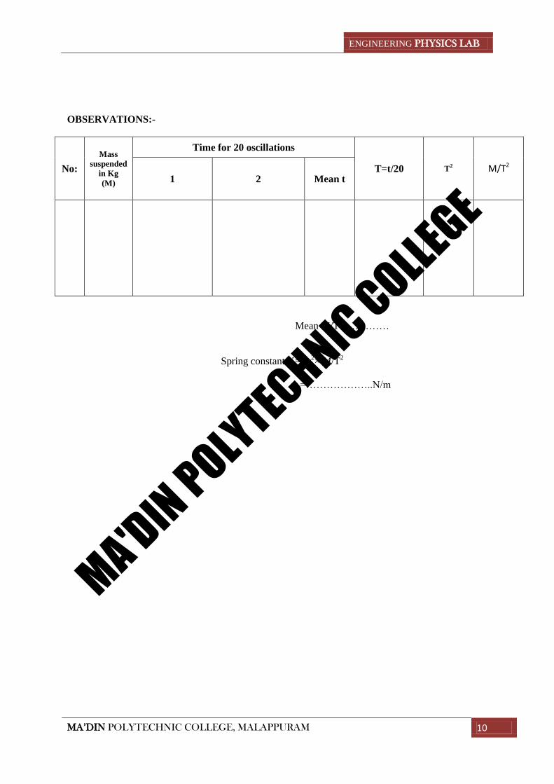
OBSERVATIONS:-
No:
Mass
suspended
in Kg
(M)
Time for 20 oscillations
T=t/20
T2
M/T2
1 2 Mean t
Mean M/T2=…………
Spring constant K=4π2× M/T
2
=………………..N/m
MA'DIN POLYTECHNIC COLLEGE
ENGINEERING PHYSICS LAB
MA’DIN POLYTECHNIC COLLEGE, MALAPPURAM 11
Expt. No:05
Date:
HELICAL SPRING II AIMS:
To determine the spring constant by oscillation method.
APPARATUS:
Helical spring,load,stop watch.
PRINCIPLE:
Spring constant K = 4π2× M/T
2
PROCEDURE:
The mass is suspended on the spring and time for 20 oscillation is measured.The mass is increased
by 50g and repeated the experiment for fve times.The mean M/T2 is measured.Then the spring
constant is given by
K = 4π2× M/T
2
RESULT:
Spring constant of the spring= …………….N/m.
MA'DIN POLYTECHNIC COLLEGE
ENGINEERING PHYSICS LAB
MA’DIN POLYTECHNIC COLLEGE, MALAPPURAM 12
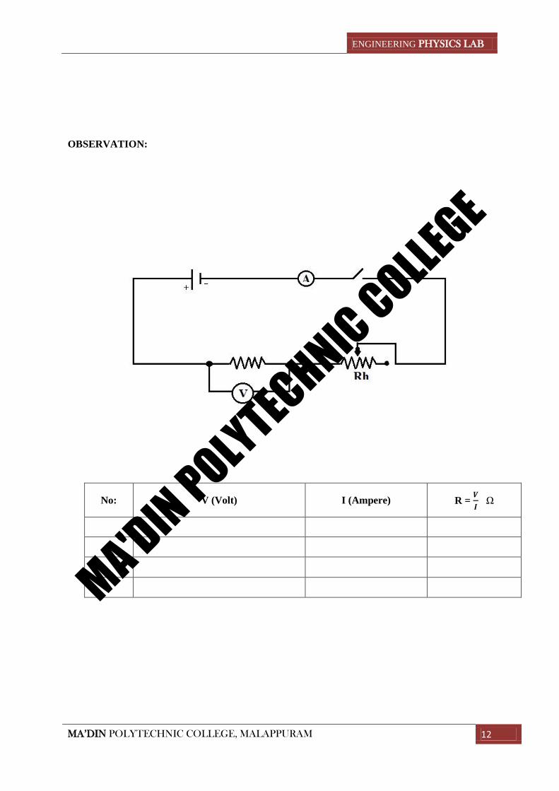
OBSERVATION:
No: V (Volt) I (Ampere) R = 𝑽
𝑰 Ω
MA'DIN POLYTECHNIC COLLEGE
ENGINEERING PHYSICS LAB
MA’DIN POLYTECHNIC COLLEGE, MALAPPURAM 13
Expt. No: 06
Date:
OHM’S LAW
AIM:
To verify Ohm’s law and to determine the resistance of a conductor.
APPARATUS:
Battery, voltmeter, Ammeter, Rheostat, Key, Resistor
PRINCIPLE:
At constant temperature, the current through a conductor is directly proportional to the potential
difference. V
I = R where R is the resistance of the conductor.
PROCEDURE:
Connections are made as shown in the figure. The rheostat is adjusted to read a potential of 1V.The
corresponding ammeter reading is noted. The voltmeter and ammeter readings are taken by increasing the
voltages in steps of 0.5V. In each case, the value of V/I is calculated. Its mean value gives the resistance of
the conductor.
RESULT:
Resistance of the conductor = …………..Ω.
MA'DIN POLYTECHNIC COLLEGE
ENGINEERING PHYSICS LAB
MA’DIN POLYTECHNIC COLLEGE, MALAPPURAM 14
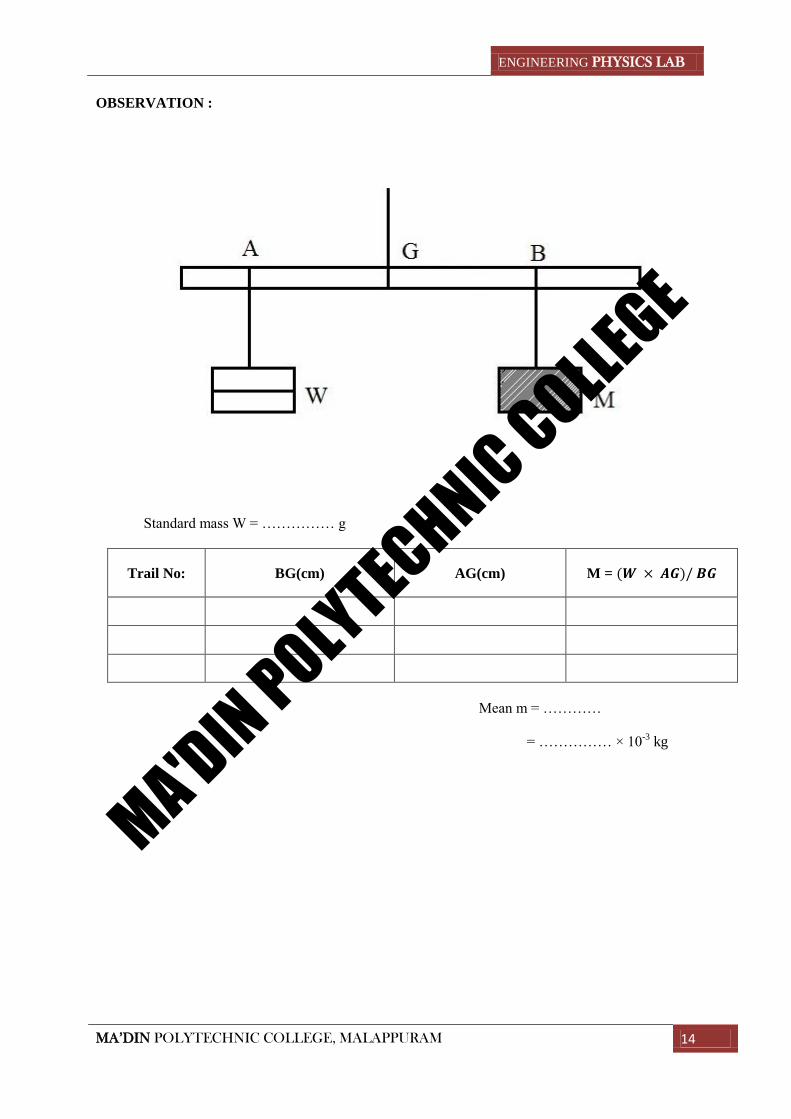
OBSERVATION :
Standard mass W = …………… g
Trail No: BG(cm) AG(cm) M = (𝑾 × 𝑨𝑮)/ 𝑩𝑮
Mean m = …………
= …………… × 10-3
kg
MA'DIN POLYTECHNIC COLLEGE
ENGINEERING PHYSICS LAB
MA’DIN POLYTECHNIC COLLEGE, MALAPPURAM 15
Expt. No: 07
Date:
MOMENT BAR
AIM :
To determine the mass of the given body
APPARATUS:
Moment bar, slotted weights
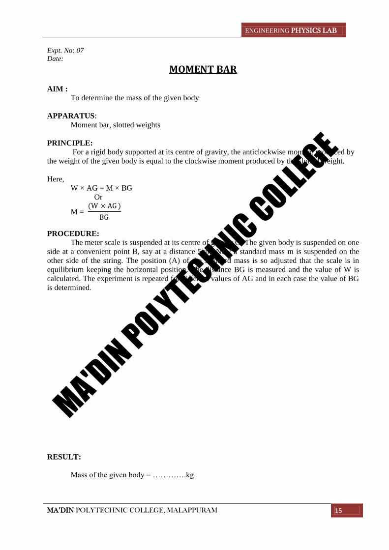
PRINCIPLE:
For a rigid body supported at its centre of gravity, the anticlockwise moment produced by
the weight of the given body is equal to the clockwise moment produced by the slotted weight.
Here,
W × AG = M × BG
Or
M = (W × AG )
BG
PROCEDURE:
The meter scale is suspended at its centre of gravity G. The given body is suspended on one
side at a convenient point B, say at a distance 5cm. Now a standard mass m is suspended on the
other side of the string. The position (A) of the standard mass is so adjusted that the scale is in
equilibrium keeping the horizontal position. The distance BG is measured and the value of W is
calculated. The experiment is repeated for different values of AG and in each case the value of BG
is determined. RESULT:
Mass of the given body = ………….kg
MA'DIN POLYTECHNIC COLLEGE
ENGINEERING PHYSICS LAB
MA’DIN POLYTECHNIC COLLEGE, MALAPPURAM 16
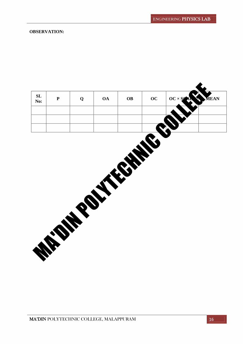
OBSERVATION:
SL
No: P Q OA OB OC OC × SCALE MEAN
MA'DIN POLYTECHNIC COLLEGE
ENGINEERING PHYSICS LAB
MA’DIN POLYTECHNIC COLLEGE, MALAPPURAM 17
Expt. No: 08
Date:
CONCURRENT FORCES AIM:
To determine the mass of a given body applying parallelogram law and by Lami’s theorem.
APPARATUS:
Parallelogram law apparatus, slotted weights
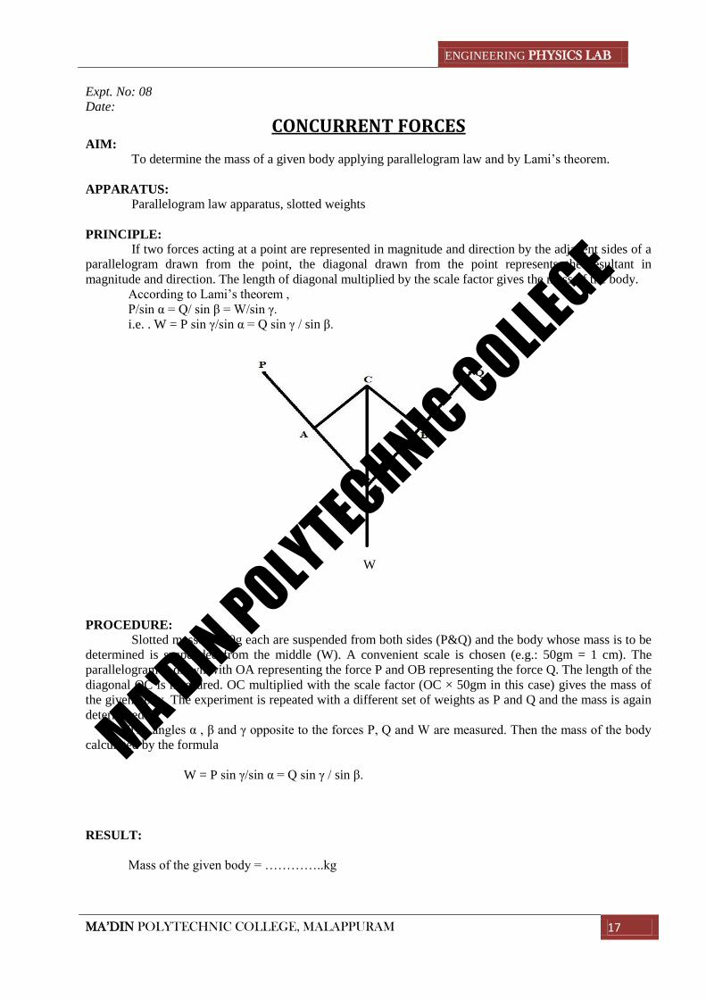
PRINCIPLE:
If two forces acting at a point are represented in magnitude and direction by the adjacent sides of a
parallelogram drawn from the point, the diagonal drawn from the point represents the resultant in
magnitude and direction. The length of diagonal multiplied by the scale factor gives the mass of the body.
According to Lami’s theorem ,
P/sin α = Q/ sin β = W/sin γ.
i.e. . W = P sin γ/sin α = Q sin γ / sin β.
W
PROCEDURE:
Slotted masses, 100g each are suspended from both sides (P&Q) and the body whose mass is to be
determined is suspended from the middle (W). A convenient scale is chosen (e.g.: 50gm = 1 cm). The
parallelogram is drawn with OA representing the force P and OB representing the force Q. The length of the
diagonal OC is measured. OC multiplied with the scale factor (OC × 50gm in this case) gives the mass of
the given body. The experiment is repeated with a different set of weights as P and Q and the mass is again
determined.
The angles α , β and γ opposite to the forces P, Q and W are measured. Then the mass of the body
calculated by the formula
W = P sin γ/sin α = Q sin γ / sin β.
RESULT:
Mass of the given body = …………..kg
MA'DIN POLYTECHNIC COLLEGE
ENGINEERING PHYSICS LAB
MA’DIN POLYTECHNIC COLLEGE, MALAPPURAM 18
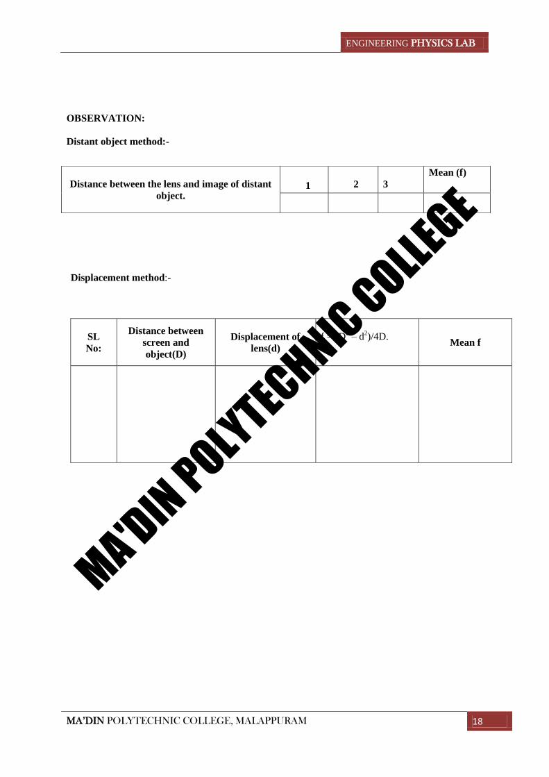
OBSERVATION:
Distant object method:-
Displacement method:-
SL
No:
Distance between
screen and
object(D)
Displacement of
lens(d)
f = (D2 – d
2)/4D.
Mean f
Distance between the lens and image of distant
object.
1
2
3
Mean (f)
MA'DIN POLYTECHNIC COLLEGE
ENGINEERING PHYSICS LAB
MA’DIN POLYTECHNIC COLLEGE, MALAPPURAM 19
Expt. No: 09
Date:
CONVEX LENS
AIM:
To determine the focal length of the given convex lens by displacement method.
APPARATUS:
Convex lens, illuminated wire gauze, screen
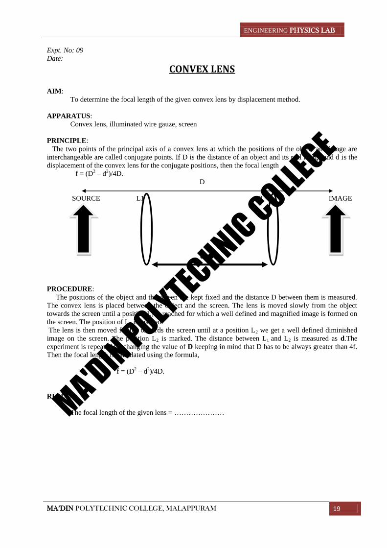
PRINCIPLE:
The two points of the principal axis of a convex lens at which the positions of the object and image are
interchangeable are called conjugate points. If D is the distance of an object and its real image and d is the
displacement of the convex lens for the conjugate positions, then the focal length
f = (D2 – d
2)/4D.
D
SOURCE L1 L2 IMAGE
d
PROCEDURE:
The positions of the object and the screen are kept fixed and the distance D between them is measured.
The convex lens is placed between the object and the screen. The lens is moved slowly from the object
towards the screen until a position L1 is reached for which a well defined and magnified image is formed on
the screen. The position of L1 is marked.
The lens is then moved further towards the screen until at a position L2 we get a well defined diminished
image on the screen. The position L2 is marked. The distance between L1 and L2 is measured as d.The
experiment is repeated by changing the value of D keeping in mind that D has to be always greater than 4f.
Then the focal length is calculated using the formula,
f = (D2 – d
2)/4D.
RESULT:
The focal length of the given lens = …………………MA'DIN POLYTECHNIC COLLEGE
ENGINEERING PHYSICS LAB
MA’DIN POLYTECHNIC COLLEGE, MALAPPURAM 20
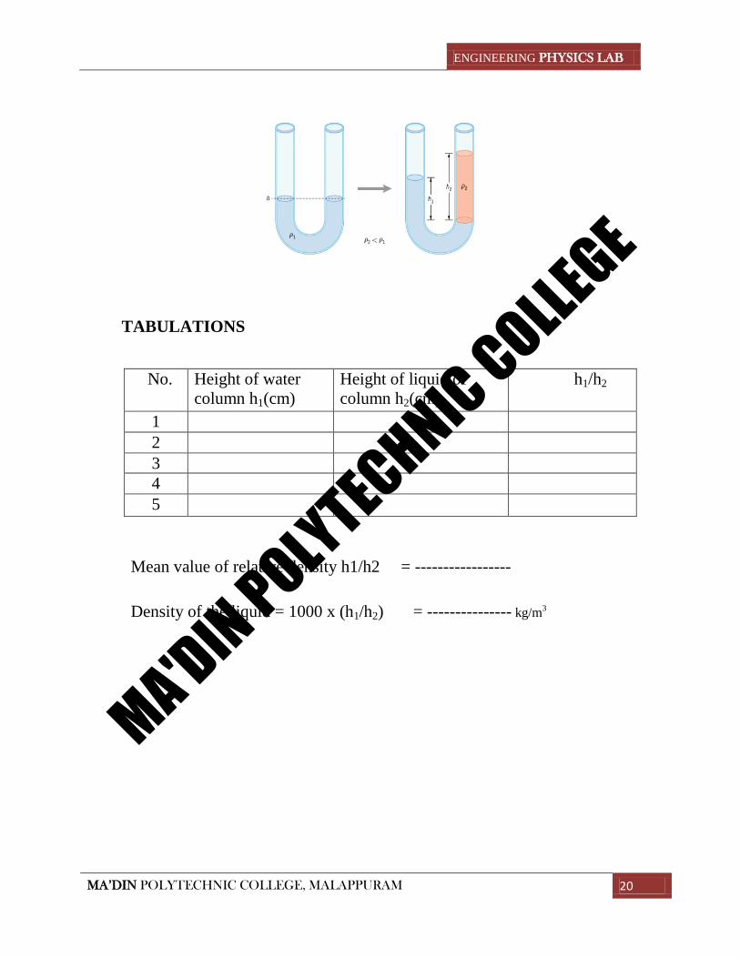
TABULATIONS
No. Height of water
column h1(cm)
Height of liquid of
column h2(cm)
h1/h2
1
2
3
4
5
Mean value of relative density h1/h2 = -----------------
Density of the liquid = 1000 x (h1/h2) = --------------- kg/m3
MA'DIN POLYTECHNIC COLLEGE
ENGINEERING PHYSICS LAB
MA’DIN POLYTECHNIC COLLEGE, MALAPPURAM 21
Expt no:10
Date:
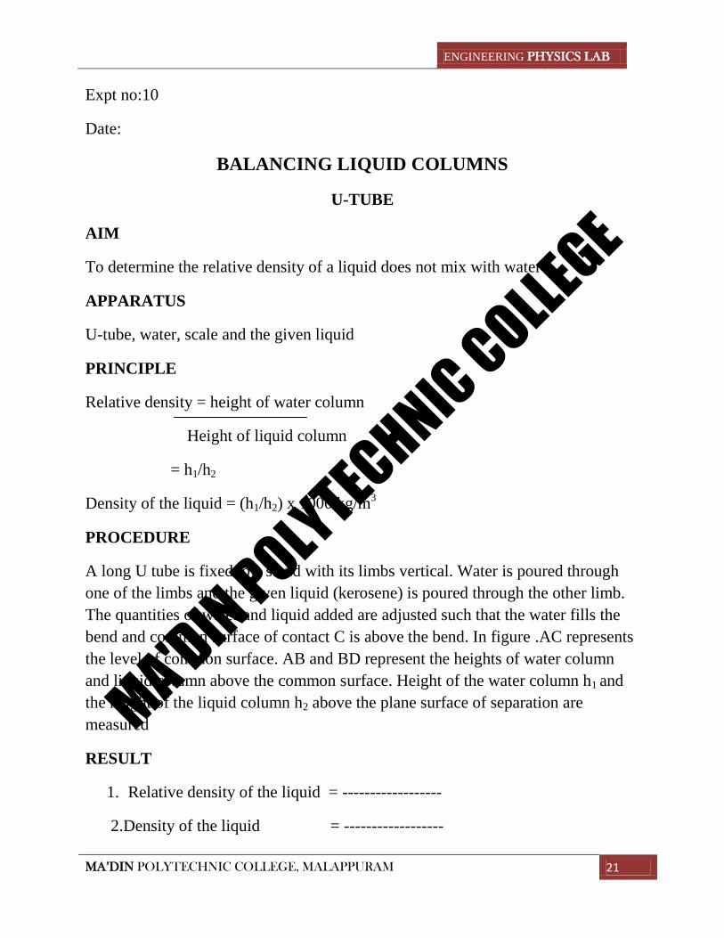
BALANCING LIQUID COLUMNS
U-TUBE
AIM
To determine the relative density of a liquid does not mix with water
APPARATUS
U-tube, water, scale and the given liquid
PRINCIPLE
Relative density = height of water column
Height of liquid column
= h1/h2
Density of the liquid = (h1/h2) x 1000 kg/m3
PROCEDURE
A long U tube is fixed to a stand with its limbs vertical. Water is poured through
one of the limbs and the given liquid (kerosene) is poured through the other limb.
The quantities of water and liquid added are adjusted such that the water fills the
bend and common surface of contact C is above the bend. In figure .AC represents
the level of common surface. AB and BD represent the heights of water column
and liquid column above the common surface. Height of the water column h1 and
the height of the liquid column h2 above the plane surface of separation are
measured
RESULT
1. Relative density of the liquid = ------------------
2.Density of the liquid = ------------------
MA'DIN POLYTECHNIC COLLEGE
ENGINEERING PHYSICS LAB
MA’DIN POLYTECHNIC COLLEGE, MALAPPURAM 22
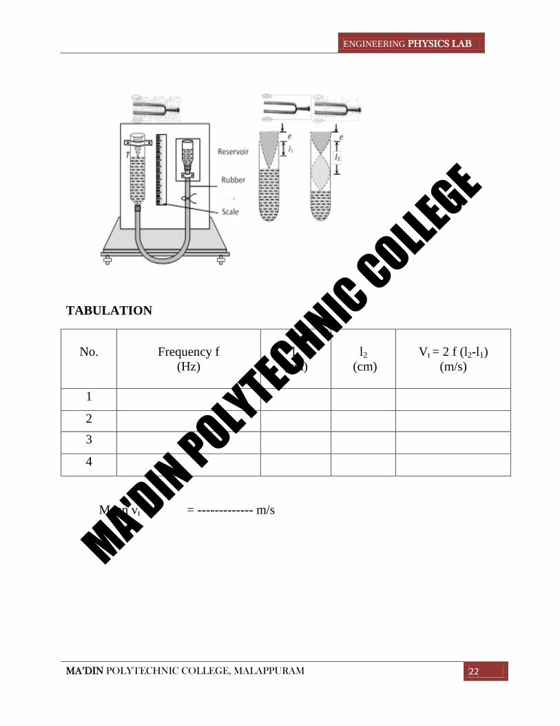
TABULATION
No.
Frequency f
(Hz)
l1
(cm)
l2
(cm)
Vt = 2 f (l2-l1)
(m/s)
1
2
3
4
Mean vt = ------------- m/s
MA'DIN POLYTECHNIC COLLEGE
ENGINEERING PHYSICS LAB
MA’DIN POLYTECHNIC COLLEGE, MALAPPURAM 23
Expt no:11
Date:
RESONANCE COLUMN
AIM
To determine the velocity of sound in air
APPATRATUS
Resonance column apparatus, tuning fork and meter scale
PRINCIPLE
If l1 and l2 are the first and second resonance lengths with a tuning fork of
frequency f, the velocity of sound at room temperature is given by the
formula
Vt = 2 f (l2-l1)
PROCEDURE
The resonance tube is initially adjusted so that the length of the air column
above water level is very small. The vibrating tuning fork is held close to the
mouth of the tube and the tube is gradually raised until the sound heard is
maximum. The length of the air column l1 is measured. The tube is further
raised keeping the vibrating tuning fork close to its mouth. When maximum
sound is heard again, the length l2 of the air column is measured. The length
l2 corresponds to the second resonant length as shown in figure. The
experiment is repeated with tuning forks of different frequencies. l1 and l2
are measured in each case. The velocity of sound at room temperature is
calculated using the relation
Vt = 2 f (l2-l1)
RESULT
Velocity of sound at room temperature = --------------m/s
MA'DIN POLYTECHNIC COLLEGE
ENGINEERING PHYSICS LAB
MA’DIN POLYTECHNIC COLLEGE, MALAPPURAM 24
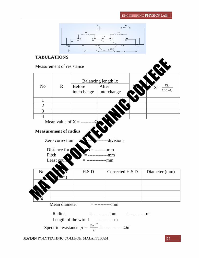
TABULATIONS
Measurement of resistance
No
R
Balancing length lx
Mean
lx
X = 𝑅𝑙𝑥
100−𝑙𝑥
Before
interchange
After
interchange
1
2
3
4
Mean value of X = ---------Ω
Measurement of radius
Zero correction = -------------divisions
Distance for 6 rotations = --------mm
Pitch = -------------mm
Least count = -------------mm
No P.S.R
(mm)
H.S.D Corrected H.S.D Diameter (mm)
1
2
3
4
Mean diameter = -----------mm
Radius = -----------mm = -----------m
Length of the wire L = -----------m
Specific resistance 𝜌 = 𝑋𝜋𝑟2
𝐿 = ------------ Ωm
MA'DIN POLYTECHNIC COLLEGE
ENGINEERING PHYSICS LAB
MA’DIN POLYTECHNIC COLLEGE, MALAPPURAM 25
Expt No:12
Date : METER BRIDGE
AIM
To determine the resistance and specific resistance of a metal wire
APPARATUS
Meter bridge, Leclanche cell, resistance box, resistance wire and table
galvanometer.
PRINCIPLE
The meter bridge is based on the principle of Wheastone’s network
PROCEDURE
The connections are made as shown in figure. A resistance of 1ohm is
introduced in the resistance box R. The jockey is moved along the wire AB
and the balancing length lx is determined here lx is the length AJ adjacent to
the unknown resistance X. When balance is obtained, the galvanometer
shows no deflection. Resistance in the box is changed to 2 ohm, 3ohm, and 4
ohm. The balance length lx is obtained in each case. The unknown resistance
X and the resistance box R are the interchanged. The balancing length lx is
measured in each case with resistance 1ohm, 2ohm, 3ohm, and 4ohm in the
resistance box. It is to be remembered that the length lx in this case is
measured from B to J because the resistances are interchanged in the gaps.
The mean value of lx is calculated for each case for each value of R.
The resistance X is calculated using the relation
X = 𝑅𝑙𝑥
100−𝑙𝑥
The diameter of the resistance wire X is accurately measured using a screw
gauge. The radius r of the wire is thus determined. The length of the wire L
is measured using meter scale.
The specific resistance 𝜌 = 𝑋𝜋𝑟2
𝐿
RESULT
Resistance of the wire = ----------Ω
Specific resistance 𝜌 = ----------Ωm
MA'DIN POLYTECHNIC COLLEGE

ENGINEERING PHYSICS LAB
MA’DIN POLYTECHNIC COLLEGE, MALAPPURAM 26
MA'DIN POLYTECHNIC COLLEGE
Related Documents