IAEA-130 ENGINEERING PROGRAMS IN RESEARCH REACTORS PROCEEDINGS OF A PANEL ON ENGINEERING PROGRAMS IN RESEARCH REACTORS SPONSORED BY THE INTERNATIONAL ATOMIC ENERGY AGENCY AND HELD IN VIENNA, 27-31 JULY 1970 A TECHNICAL REPORT PUBLISHED BY THE INTERNATIONAL ATOMIC ENERGY AGENCY, VIENNA, 1971

Welcome message from author
This document is posted to help you gain knowledge. Please leave a comment to let me know what you think about it! Share it to your friends and learn new things together.
Transcript

IAEA-130
ENGINEERING PROGRAMSIN RESEARCH REACTORS
PROCEEDINGS OF A PANELON ENGINEERING PROGRAMS IN RESEARCH REACTORS
SPONSORED BY THE INTERNATIONAL ATOMIC ENERGY AGENCYAND HELD IN VIENNA,
27-31 JULY 1970
A TECHNICAL REPORT PUBLISHED BY THEINTERNATIONAL ATOMIC ENERGY AGENCY, VIENNA, 1971

The IAEA does not maintain stocks of reports in this series. However,microfiche copies of these reports can be obtained from
INIS Microfiche ClearinghouseInternational Atomic Energy AgencyKarntner Ring 11P.O. Box 590A-1011 Vienna, Austria
on prepayment of US SO.65 or against one IAEA microfiche service coupon.

PLEASE BE AWARE THATALL OF THE MISSING PAGES IN THIS DOCUMENT
WERE ORIGINALLY BLANK
FOREWORD
The Panel on Engineering Programmes in Research Reactors was thefirst organised by the IAEA on this subject. This Panel was held atthe Agency Headquarters in Vienna, Austria? during the 27 - 31 July,1970.A total of 28 scientists from 18 countries and an international organiz-ation participated in this meeting.
These proceedings constitute an informal record of the meetingand of the main points brought out during the discussions. Some papershave been shortened leaving only those matters pertaining to the specifictopic of the Panel.
The proceedings have been prepared by the Agency's staff and theversions of the papers given here have neither been checked nor edited bythe authors concerned. It is hoped that this record of the meetingwill provide useful information regarding possibilities and new approachesto increase engineering research,development and testing in the existingand future research reactors. This volume-might serve to stimulate theengineering effort of the reactor centres concerned'and promote col-laboration among them for mutual benefit.
The Agency wishes to express its sincere appreciation to theco-chairmen Mr. A.J. Mooradian and Mr. J. Spitalnik, and also to allthe other members of the Panel.
TABLE OP CONTENTS
ForewordEngineering Programmée in Research Reactors - 1Background Paper, B. Kolbaaov, H. Gonzalez-MontesEngineering Programmes in 'Democritos* Research Reactor 17N.G. ChrysochoidesThe Whiteshell Nuclear Research Establishment, Its 33Significance and DevelopmentA.J. MooradianThe Organization and Function of Design Services 55Departnent of Research Reactor DivisionF, TaylorStatus Report of the Engineering Programmes at the 63Reactor Center Seibersdorf, AustriaA. BurtscherA Brief Note on the Use of Research Reactors at 69A *E>R*E«F. TaylorSummary of the Engineering Programmes Performed 73in the Belgian Research ReactorsG. StiennonInstalaciôn de un Reactor de Investigaciôn en un pais 87en desarrollo (A Research Reactor Facility Installationin a Developing Country)J. SpitalnikEngineering Programme at the Finnish TRIGA Research 99ReactorA. PalmgrenExamples of the Usa of Low-Power Reactors for Studying 109Problems connected to Development and Operation ofPower ReactorsK. SaltvedtSummary Report on the Use of Research Reactors in the 133Programme of Research and Development of NuclearPower in YugoslaviaN. RailicIndian Nuclear Effort, Status Report 139S.M. Sundaram, N. Veeraghavan, 1Î.R. Rao

ABCL's Engineering Programmes in Research Reactors 145J.A.L. Robert sonEngineering Programmes in the EURATOM Research Reactors 161H. EhringerExperiencias de Ingenieria con el Reactor JEN-1 179(Engineering Activities in the JBN-1 Research Reactor)J. Hontes Ponce de LéonProgramas de Ingenieria en los Reactores Argentines 191(Engineering Progr&œnes in the Argentine Reactors)J. Cosentino at al.Some Examples of Research Reactor Utilisation, Costs 201and Trends in the U.S.D.H* LennozScope and Possibilities of Engineering Programmes in 217the U.A.R. Research ReactorO..H. El/Mofty, M.F. El/Fouly, M.A. Hassan
nccjie,nOBaTejn>CKoro peaKïopa B EojirapwH 225pemeHna npofijieM HjtepHoft oHepreTHKw
P.reoprweB (The Use of the Research Reactor in Bulgariafor Solving Nuclear Power Problems)R. GeorgievUses of TRIGA Research Reactors for Engineering Research 231Testing and TrainingO.T. Schnurer,,A.T. McMain and P.U. FisherSummary of the Current Engineering Programme in the 25750 HW R2~ReactorK, Saltvedt!!an Power Re virements and Engineering Programmes Using 271Research Reactors in Conjunction with Nuclear PowerReactor ProcurementH.R. KleijnResearch Reactor Utilization in the Context of Nuclear 285Power Programme in Developing CountriesS.M. Sundaram, N. Veeraghavan, K.R. RaoReview of Research Reactors, Their Use and Some Engineering 295Programmes in GermanyK.B. KfiperDispositifs d'Irradiation (Irradiation Devices) 303II. Seguin
Experimental Techniques for Fuel Testing in Research */-ReactorsN. RaisicProblems Involved in the Procurement of In-pile 379Assemblies for Nuclear ResearchH. Straton, F. TaylorQuelques aspects sur l'utilisation du réacteur roumain 383de recherche dans le génie nucléaire. (Some Aspects ofthe Utilization of the Romanian Research Reactor inNuclear Engineering)P. PopaSome Comments on Papers Presented to the Panel 38?J.A.L. RobertsonConclusions and Recommendations 391List of Participants 399

ENGIHBBRINQ PROGRAMMES Iff RESEARCH REACTORS(Background Paper)
B, Kolbasovand
H* Gonzalez-MontesIAEA
I. Introduction
The use of nuclear power in the developing world for the productionof electricity is an established fact. Power reactors are in opera-tion in Spain and India and under construction in Czechoslovakia,Pakistan, Argentina, Bulgaria and Korea. Definite plana.for powerreactors have been announced by the Republic of China, Hungary,Mexico, Romania and Thailand and, .in the near future, Brazil, thePhilippines, Poland, Chile, Israel, the United Arab Republic,Yugoslavia and Turkey are expected to announce definite commitmentsto the inclusion of nuclear power in their national electrical grids.Some other developing countries have-expressed interest in preparingthemselves for timely and economical introduction of nuclear power.
The implementation of a national nuclear power programme in anycountry is practically impossible without the necessary engineeringknowledge. Even if the power producing equipment is purchased abroad,,it is essential to have trained nuclear engineers and scientists who .,are capable of participating in the establishment of the system andhelping with thd preparation of specifications. A great deal of thismuch needed nuclear engineering background can be obtained throughthe use of research reactors. These reactors, serving as neutronsources, are a comparatively new research tool to be used in experi-ments in different branches of engineering.
Since there is much engineering to be done in the field of nuclearpower, the introduction and increase of engineering activities in theHeactor Programmes would certainly contribute towards both a) thecreation of a much needed basis for engineering developments andb) the better utilization of the existing reactor centres themselvesin developing countries.
1

Taking into consideration the goals and extent of participation thatdeveloping countries can afford to "be involved in, this Panel shouldconsider two different groups of countries:
a) Those interested in participating in the developmentof nuclear power technology (beginning perhaps with oneor more branches of nuclear technology);
b) Those only interested in the efficient utilization oftheir nuclear reactors.
Before drawing up this Background Paper, the Scientific Secretariesof the Panel corresponded with some leading experts in the field onan informal basis and gained very valuable advice and ideas. Theyare particularly grateful to Messrs. A.J. Mooradian (Canada) andBailey (USA) for their advice and thoughts, many of which are in-cluded in this Paper. We are also thankful to Messrs. C. Araoz(Argentina-)» J« Spitalnik (Uruguay), N. RaiSio (Yugoslavia)B. Prakasli (India), P. Leveque (Prance), K. Saltvedt (Sweden)H. Mondin (Prance), J. Montes Ponce de Léon (Spain), J. Cosentino(Argentina), J. Sabato (Argentina), ZbShlik (Czechoslovakia) andothers for their useful comments.
II. Research Reactor Utilization and the PanelThe Agency has a long-standing, active programme in research reactorutilization. The major items in this programme are considered by aseries of Regional Study Group meetings held throughout the world.At those meetings, reactor users exchange experience with each otheras well as with experts in specialized fields from advanced countries.So far, there have been six meetings in South Asia and the Par East,four in Europe and the Middle East, and three in Latin America. Manyof them have been documented in reports-/ which can be had from theAgency upon request.
Additionally, the Agency sponsors other activities to improve the useof research reactors^/. These include publication of safety guidesand manuals, promoting research aimed at demonstrating profitable andinexpensive research fields; support of research with the aim ofsimplifying and reducing the cost of certain types of experiments;

issuance of standard samples and materials for monitoring radiationin and around reactors, and manuals for their use as well as manualson experimental techniques, equipment design, and so forth; and,occasionally, provision of standard experimental facilities for co-ordinated research programmes. The Agency has also supplied individualand group training programmes and sponsored the activities of expertin reactor utilization; finally, the staff of the Agency is able, onrequest, to furnish advisory services on reactor planning and utili-zation.
Engineering studies in reactors have also furnished the themes formeetings and discussions sponsored by the Agency.
2/For example, "Reactor Shielding11—' was a theme of a panel held inVienna, 9-13 March 1964; "Fuel Burn-up Predictions in ThermalReactors11"*' were discussed at a panel held in Vienna 10 - 14 April 1967?the "International Summer School for Heat and Mass Transfer in Flowswith Separated Regions and Measurements Techniques" was held in thesame place from 1-13 September 1969» A panel on "Instrumentationfor Nuclear Power Plant Control" was held in Vienna from 17 - 21 November1969.
Thus, this Panel on Engineering Programmes in Research Reactors isbut one part of a comprehensive Agency programme in support of researchreactor utilization and nuclear power in developing countries. It isbeing organized by the Research Reactor Section of the Division ofNuclear Power and Reactors with the specific purposes stated below.Nevertheless, this Panel meeting is the first on this topic organizedby the Agency. . „
111 • (Steals of the PanelThere is no limit to the number of possibilities for fruitful actionby the Agency in the field of engineering programmes in research reactors.The resources of the Agency and of its Member States, available forthis purpose are, however, limited. Hence, well considered decisionsas to the proper use of these resources are of great significance.

Due to the extreme importance of engineering programmes in all phasesof nuclear power engineering and because of the diversity of nuclearpower development in .different countries,, the Agency should not onlybe kept, informed of .the engineering studies carried out by the MemberStates but it should also be prepared, in case of need, to offer adviceand assistance to its Member States, in particular to developing countries.
This Panel, therefore, will be asket' to explore the possibilities offurther efforts by the Agency in support of engineering programmes inresearch,reactors, and to recommend activities in which concentratedattention should be directed. In particular, it should stress suchengineering programmes which can be undertaken at smaller reactor centres.
Below we state the main, goals of the Panel.
1) The Panel should evaluate the utility and the most reasonable waysof using research reactors for the study of nuclear engineering problemsarising in the nuclear programmes of the developing countries, particularlythose with plans for nuclear power. It should determine what can andshould be done in this field by the Member States.
The Agency hopes that the Panel will stimulate and help specialists indeveloping countries to develop the engineering research capabilitiesrequired for the successful establishment and realization of nuclearpower programmes} such programmes might include planning for largerresearch facilities in the future.
2) Recognizing that there are many developing countries which haveresearch reactors but do not have near-term definite plans for nuclearpower engineering, the Agency would also ask for advice on whether and,if so, what useful engineering research programmes should be recommendedto reactor centres in such countries.
3) The Panel should review and exchange information on the presentstatus, and prospects of engineering studies being carried out in theresearch reactors of the Member States as well as on the ways ofpossible mutually beneficial co-operation in this field. Such informa-tion would be particularly useful to developing countries beginning todevelop their own programmes of research.

4) The Panel should examine the role of the Agency in aiding the useof research reactors for engineering studies and should determine whatcan (or cannot) toe done by the Agency. It should formulate recommenda-tions to the Agency in connection with a programme to facilitate andpromote the efficient use of research reactors in the engineeringprogrammes of the Member States.
IV. AgendaThe Panel should hear and discuss presentations under the headingslisted "below.
A. IntroductionThis background paper states the goals of the Panel and sketches some ofthe areas of engineering programmes in which research reactors in developingcountries can be used, and which should be the concern of the furtherdeliberation of the Panel. The scope of the Panel, as well as the mostgeneral problems and difficulties of engineering studies in researchreactors will be sketched by discussion of the background paper andrelated presentation.
B. Status ReportsThese will be written summaries of needs, resources, and current andplanned activities in the engineering programmes in research reactorsof participating states, with brief oral presentation and with discussionby the Panel.
C. Discussion of Some Aspects of Engineering ProgrammesThe Panel will hear and discuss presentations of the possibilities forthe effective employment of research reactors in the following areas ofengineering studies»
1. Reactor fuel and material development}2. Heat transfer and fluid flow;3* Instrumentation development;4. Reactor chemistry.

These areas are selected to be representative of the possibilitiesand problems of engineering programmes in research reactors, particularlyof developing countries.
The topics that should be discussed under each of the technical headingsare:1. General problems of engineering programmes in research reactors.Their interdependence with nuclear power programmes and possiblebenefits.2. Experimental base for nuclear engineering research»3« Availability of trained personnel.4« Capital investment and cost of the programmes.5. Detailed analysis of some programmes, as examples.
D. ContributionsEach participant is encouraged to present, in writing and-in shortoral summary, a contribution on any topic relevant to the theme ofthe Panel. Additional contributions can be made in writing and willbe included in the official record of the Panel.
E. RecommendationsAs a result of discussions, groups of participants appointed by thePanel should formulate recommendations to the Agency and to the MemberStates on future activities connected with the utilization of researchreactors in engineering research.
This agenda is not intended to be final. The Panel .itself will beinvited to make further contributions before adopting the Agenda.
V. Discussion; A.Interdependence of Nuclear Power Programmes andNuclear Engineering Research.
The main purpose of engineering programmes in research reactors is toprovide for the successful execution of national nuclear power programmes.It is no mere chance that the main .difficulties as for nuclear engineeringresearch programmes and poor use of research reactors in developing

countries are usually "bound up with the lack of national nuclear powerprogrammes. Therefore, it is useful to consider this connection atgreater length.
Any sound national nuclear power programmes rests on three corner-stones»l) scientific "base; 2) technological and engineering "base? 3) industrialbase. Let us consider their interdependence with engineering research.
l) Scientific BaseMost national institutes "begin their,nuclear research activity with astrong emphasis on the scientific aspects of nuclear energy programmes.Generally, at first there is a failure to recognize the broad spectrumof scientific disciplines which are involved in the national programme.Too often, the scientific strength of an institute is overbalanced onthe side of nuclear physics or possibly radiation chemistry. Theimportance of an engineering research programme is that it very quicklybrings to light the need for broadly based scientific support activitycovering a multiplicity of disciplines such as metallurgy, ceramics,coolant chemistry, surface chemistry, physics, corrosion, electronics,non-destructive testing, hydro-dynamics, mass and heat transfer, computerscience, nuclear instrumentation, etc.
A properly conceived engineering programme will make it quickly apparentthat no one discipline can, in fact, dominate the institute and that abalanced approach is necessary. Having defined the need for a broadbase of scientific disciplines, it follows that the size of the scientificestablishment needed also comes into focus.
2. Technological and Engineering BaseIt is self-evident that an engineering research programme will directlyassist the building of such a base. The engineer, to function properlyrequires not only continuous consultation with scientists but also thehelp of technologists with the skills needed to execute such a programme.One has only to carry through a modest programme to appreciate what isinvolved in developing a whole reactor system. This is a particularlyimportant point, since the most common weakness encountered in relativelyyoung institutes is that the level of engineering and technological supportis often the weakest part of the activity.

A good engineering research programme will act as the training groundfor the many specialized skills needed to launch the industrial nuclearsector. This is the place one would expect to spawn the domesticconsultants of the future. Unfortunately, the utilization of researchreactors in technological developments is scarce in developing countries.
3. Industrial BaseOne of the important aspects of an engineering programme is that itopens the door to industrial participation and helps to create astructure where the industry may have'an active part in the futureprogrammes on nuclear power.
It is profitable to get industry interested and involved in utilizingthe facilities of the reactor centre, as the industry has the meansof supporting research and is in the best position to turn researchresults into productivity. The engineering programme offers, generally,the first opportunity which the domestic industry has of recognizingthe skills which must be developed in order to meet the requirements ofa nuclear energy programme.
It is essential for developing countries to try to utilize, as much aspossible, the local facilities, industry and labor, in order to avoidexcessive drain of their foreign exchange resources. The well establishedengineering programmes at the research reactor centres will, undoubtedly,raise the level of local industry toward the goal just mentioned.
B. Experimental Base for Nuclear Engineering Research^Undoubtedly, the possibilities of any reactor centre and a country onthe whole depend very much upon the types of available reactors. There-fore, it is useful to consider different types of research reactors inconnection with their experimental potentialities.
Heaotors with neutron flux below 10 /sec cm , of which 7 exist indeveloping countries, should be considered as zero-power reactors, i.e.as one which requires neither protective shielding nor special precautionsin approaching of its components after shut-down. This accessibilitymakes it useful for such purposes as : teaching, studies of the chainreaction mechanism, study of effects of unusual devices (controls, cooling
8
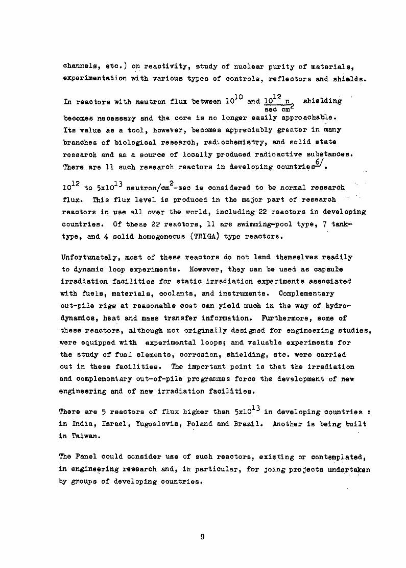
channels, etc.) on reactivity, study of nuclear purity of materials,experimentation with, various types of controls, reflectors and shields.
In reactors with neutron flux "between 10 and 10 n shieldingsec cm
"becomes necessary and the core is no longer easily approachable.Its value as a tool, however, "becomes appreciably greater in manybranches of biological research, radiochemistry, and solid stateresearch and as a source of locally produced radioactive substances.There are 11 such research reactors in developing countries—/*
n p -I •% o .10 to 5*10 neutron/om -sec is considered to be normal researchflux» This flux level is produced in the major part of researchreactors in use all over the world, including 22 reactors in developingcountries. Of these 22 reactors, 11 are swimming-pool type, 7 tank-type, and 4 solid homogeneous (TRIGA) type reactors.
Unfortunately, most of these reactors do not lend themselves readilyto dynamic loop experiments. However, they can be used as capsuleirradiation facilities for static irradiation experiments associatedwith fuels, materials, coolants, and instruments. Complementaryout-pile rigs at reasonable cost can yield much in the way of hydro-dynamics, heat and mass transfer information. Furthermore, some ofthese reactors, although not originally designed for engineering studies,were equipped with experimental loopsj and valuable experiments forthe study of fuel elements, corrosion, shielding, etc. were carriedout in these facilities. The important point is that the irradiationand complementary out-of-pile programmes force the devalopment of newengineering and of new irradiation facilities.
There are 5 reactors of flux higher than 5x10 ^ in developing countries *in India, Israel, Yugoslavia, Poland and Brazil. Another is being builtin Taiwan.
The Panel could consider use of such reactors, existing or contemplated,in engineering research and, in particular, for joing projects undertakenby groups of developing countries.

Many experts feel strongly that it would be a great mistake toencourage any developing country to believe they can mount a soundnuclear power programme without the benefit of a first-rate engineeringirradiation facility. According to this view, if any country wants tocreate nuclear power engineering by their own means, a vigorous loopprogramme and respective first-rate research reactor to carry outexperiments covering the spectrum from capsules to full scale aridpressure tube assemblies are necessary. Without such facilities, itis difficult, if not impossible, to focus scientific and engineeringresources of the country and to develop nuclear power engineering.No country seriously interested in nuclear power could afford to bewithout such facilities - it is one of the necessary costs of gettinginto the game. This would hold equally for those countries which intendto buy their first nuclear power units abroad as it would for those whichintend to produce them completely or partially at home.
Undoubtedly, a utilization programme, in particular and engineeringone, should have been planned in considerable depth before procuringa reactor. Additionally, the prior existence of a significant numberof scientists and technicians should be provided. However, the actualstrategy which a country can afford to adopt is, of course, dictatedby its resources, and in some cases the reactor purchase has been madebefore the plan for utilization has been completed. In those countrieswhere the facilities are limited to small research reactors, theengineering programme can find a logical focus on problems associatedwith the next major irradiation test facility needed to build thetechnological corner stone of the national nuclear power programme,
The experiments should be aimed at developing the information neededto improve the quality of decisions which will have to be made as tothe type of advanced irradiation facilities needed. The discussion ofthese opinions at the Panel could be useful.
C. Availability of Trained Personnel -•One of the main reasons which prevent successful establishment ofnuclear engineering programmes in developing countries is the shortageof experienced national scientists, engineers and technicians capableof directing and carrying out these rather complicated programmes.
10

At nuclear engineering research facilities, national specialists candevelop a competence in things nuclear in general, in the "bas.ic. engineer-ing arts and "sciences, and, in particular, a competence in the abilityto analyze reactor systems both analytically and through an intuitivefeeling about the nature of the problem. In particular, the necessaryactivities around a research reactor provide experience in such fieldsas control operations, equipment maintenance, chemical analysis, healthphysics and electronics or prototype operations for power reactors.
The national specialists, trained with a well developed man-nuclearsystem relationship, should form a qualified national team of engineersto consider and study, when the time comes, the proposals for commercialnuclear power plants. This relationship, once developed, should also behelpful when the specialist secures the economical operation of the plantand designs, or analyze any nuclear system. The great need for theability to analyze reactor systems is especially felt in the time of .troubles at the nuclear power station.
The senior utility operating, reactor design, and control board staff,and even senior industrial staff, oan cut their teeth in advance onprogrammes associated with nuclear engineering test facilities.
On the other hand, the realization of engineering programmes in researchreactors may make it easier for a country to retain scientific personneltrained in nuclear and other fields, who might otherwise emigrate toother countries.
It seems highly desirable that the research reactor centre should main-tain close cooperation with universities and other scientific laboratories.
In this way, the reactor centre can secure a constant supply ofengineering manpower, new ideas and research know-how, which areessential for the activity of the cefttre. Moreover, the inter-action of engineering and scientific skills is a requirement forthe initiation of useful applied science research which is oftenoverlooked by university-trained scientists.
11

D. Types of Engineering Studies in Research ReactorsThe efforts in research reactors under limited ."budget conditions mustbe well defined in relation to purposes and subjects in order to giverealistic programmes and useful results.
When we ask for what purpose the engineering programme has to be drawnup, it is possible to consider two different purposes of developingcountries:
a) To develop capability to be a good buyer and operator;b) A more ambitious one, of selecting some branches of nuclear
technology to start a nuclear industry.
The engineering research programmes are of great assistance in anycountry because they tend to focua the multiplicity of skills anddisciplines which are used in experimental programmes, into a con-centrated effort.
When we ask at what main problems an engineering programme must befixed in a developing country, it is possible to consider to options:1) The programme can focus on the gaps in the existing technologies.It is a mistake to assume that all sources of uncertainty have beenresolved, even with so-called reactors of the proven types. Thereis much left to learn about all aspects of reactor technology. Theknow-how rests largely on empirical experiments. One should not besurprised to encounter troublesome phenomena which fall outside thenarrow envelope of empirical test work.
The programme of the experiments need not be at the glamorous fore-front of the field to be valuable.
2) A very large programme of challenging work can be developed inanswer to the following question "What is limiting the performanceof the existing reactors? Are such limits dictated by nature orcan they be extended by new technology?"
Here, a great deal of care is required to identify the most importantlimiting criteria and in particular thq.se which will yield to valuableeffort. There is a natural temptation in such a programme to dissipate
12

effort over too broad a field. It requires a highly disciplined approachto confine attention to selected key areas of work and to focus theavailable resources on such areas.
E. Selected Technical Topics
Four.areas of engineering studies were selected for discussion at thePanel?-they are representative of the possibilities and problems «netin engineering programmes in research reactors. They seemed mostappropriate for investigation of the problems stated as goals of thePanel•
1» Reactor Fuel and Material Development'"
Fuel elements are prepared and irradiated and the changes in theirmaterial properties are measured* These may include changes in dimensions,crystalline structure, thermal conductivity, strength, etc. The formationof clearances between components of fuel elements as well as release offission products can also be studied.
Specific materials intended for fuel-element cladding as well asmoderator, shielding, control or structural material may also be irradi-ated and the effects studied. Cladding materials can be examined bothseparately and as parts of the fuel elements depending on the specialfabrication conditions of the elements.
In some reactors, shielding materials and substructures can be testedfor neutron and gamma shielding ability and for integrity under irradi-ation. Such studies can be of great interest to developing countrieswhich wish to use local materials for shielding and substructure ofreactors.
Finally, research reactors might be helpful in developing non-destructivetesting techniques which can be applied to power reactor components, orto monitor burn-up or to locate a fuel element which has been leaking.Techniques available include neutron radiography, gamma-spectroscopyand delayed neutron monitoring, among others.
13

2. Heat Transfer and Fluid____In connection with fuel development, it is useful to examine limits ofthermal performance of a specific fuel of power reactors and respectivecoolant configuration in a specific reactor field. Of particular impor-tance are such general problems as flattening of core power density, hotspot investigations, local fuel temperatures/ and transient effects ofpower surges» Also, some questions, specific for certain reactors, suchas* burnout, departure of nuclear boiling, critical heat flux ratio,flashing, complicated phenomena in liquid metal heat transfer, efficiencyof fins of fuel elements, heat exchange in axial flow of fuel rod bundles,are of importance.
The cooling of research reactors .themselves can also contribute..to thetheme of discussion at the Panel.
Unfortunately, it is very difficult to carry out heat transfer and fluidflow experiments of interest to power reactors in research reactors evenwith intermediate neutron flux.
5/3- Ins tr ument ati on Bevel opinent^ 'Reactor beams and low-level flux areas are very convenient for feasibilityand life testing of radiation instrumentation. New concepts for high-radiation-level instruments, or the serviceability and problems of standardequipment can be tested by irradiation in or near the core. Researchreactors can also be. used for calibration of some instrumentation.Ideas for control devices are subject to service tests.
One of the problems is the use of modern and classical automatic controltheory as it relates to "system identification".
4» Reactor ChemistryIncluded here are programmes in water processing? consequences of claddingfailure: activation of technical materials; corrosion, etc. The behaviourof various coolants under irradiation and their chemistry control as wellas compatibility of coolants with various reactor materials under conditionsof radiation and stress typical of power reactors would be an importantaspect to consider.
14
Facilities, loops, and other experimental equipment of research reactorsfor engineering studies as well as different experimental procedures areof particular interest for consideration at this Panel; pre-irradiationand post-irradiation engineering research, some aspects of hot celloperation, vacuum engineering and radioactive material handling, canalso "be considered in connection with the above-mentioned engineeringprogramme topics.
REFERENCES
1. Proceedings of the following Study Group Meetings in Research ReactorUtilization» Bangkok, 1962} Athens, 1963$ Sao Paolo, 1963; Manila , 1963;Bucharest, 1964; Istanbul, 1965, Caracas, 1965, Lucas Heights, 1966,(the above three published as one volume: TES N 71» IAEA, Vienna, 196?)jBogota, 1967; Tokyo, 196?.
Published by the I.A.E.A.
2. Reactor Shielding, Technical Report Series #34, IAEA, Vienna, 1964.
3. Fuel Burn-up Predictions in Thermal Reactors, Panel Proceeding Series,IAEA, Vienna, 1968.
4. Instrumentation for Nuclear Power Plant Control, Technical ReportNo. 119, IAEA, Vienna, 1970.
5« B.I. Spinrad, Y. Tchernilin; "Role of Research Reactors in DevelopingCountries", Peaceful Uses of Atomic Energy in Africa (Proc. Symp.Kinshasa, 1969), IAEA, Vienna, 1970.
6. Power and Research Reactors in Member States, IAEA, Vienna, May 1970»
15
ENGINEERING PROGRAMMES IN
DEMOCRITOS RESEARCH REACTOR
K. G. ChrysochoideaNuclear Reactor Center "Democritos"
Athens
1 Abstract
The Greek research reactor, GRB-1 , of the Nuclear ResearchCenter ."Democritos" has beep used during the last years for thestudy of some er^Jneerinw' pr OPT arme E .
The percentage of these pro^ramr.es in a research reactor is,for the case of developing countr ies , usua l ly small compared to theother activities in the reactor.
The importance cf engineer-in^; programres in research reactorsis obvious, particularly for developing countrn ps facinp thequestion of j notallatior; of nuclear pov/er plants.
The role of tre A~pro,y wcu] d be the coordinat ion arcorp
countries or probl ems of common interest anci the support ofengineering programmes in developing countr ies .
lut rod u c t i^ j^ n
Tho actual activities in the Nuclear Field startedin Greece about 9 years ago when a 1 MW swimming-pooltype reactor went critical in July 1961.
The reactor belongs to the Greek Atomic EnergyCommission and is installed at the Nuclear ResearchCenter "Democritos %, which includes today many otheractivities besides ,Kuclear Engineering and has a totalstaff of about 650 people.
The question of installing nuclear power plantsin Greece was first considered in 1966. Two years la-ter, a feasibility study was completed which lead to
17
the conclusion that a nuclear power reactor of about4-50 MWe, could be accepted in the Greek grid by 1975,with economically competitive price to conventionalplants /f*l_7. As a next step, négociations were startedwith foreign firms for the supply of a nuclear plant.
The existence of the research reactor was of out-most value to the nuclear power programme. Experiencedpeople were drawn from the reactor group to assist inthe various aspects of the nuclear power programme,including safety and siting problems. .Engineering pro-jects which were carried-out at the research reactor,gave an opportunity to have better understanding ofthe various problems to be faced with the power reactor.
The up to now experience is that the successfulrealization of a nuclear energy programme in a countryis very much related with the existance of a thoroughlyplanned and well justified engineering programme withthe research reactor.
In order to increase this contribution of theresearch reactor to the country's nuclear power program-me, the power of the Greek research reactor will beraised by the beginning of next year from 1 to 5
I. THE RE&SA3CH REACTOR AM) ITS CONNECTIONWITH THÏÏ POtfSH PROGRAMME
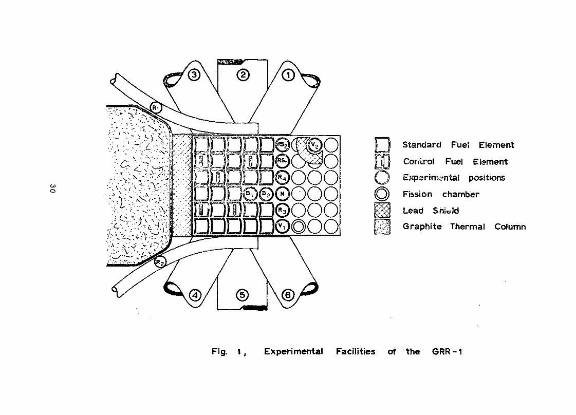
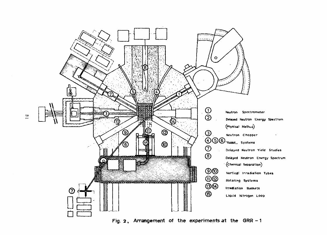
The Greek research reactor, GRR-1, is of the swim-ming pool type, operating at 1 MW with several experi -mental facilities including beam tubes, pneumatic trans-fer systems, spécial"activation facilities and loops.In fig. 1, the experimental facilities of the reactorare shown.
There are several research projects carried out atthe reactor. In fig. 2 the arrangement of the various
18
experiments around the reactor is given. Most of theprojects are connected with nuclear and neutron physics,nuclear chemistry and activation analysis. There isalso a large programme of radioisotope production.
A relatively small portion of the activities,about 10-15% are devoted to tha direct or indirect servi-ce of power reactor programmes. Some of these pro-grammes are connected with physics problems related topower reactors while some others are related to engineer-ing, instrumentation and chemistry.
1. PIIÏ3IC SSeveral physics projects performed with the reactor
load to some useful results for power reactor programmesSuch projects were:
The total neutron cross section of EL O and D^Q atroom temperature and 200°C, was measured in responseto an EANDC request, using a fast chopper spectrometer.
b.In a series of experiments, the temperature coef-
ficient at zero power for individual cells of the react-or core and reflector, was measured. From the dataobtained, the temperature coefficient of the reactor atvarious operational conditions at power can be predicted.
This project which is still in progress, aims todetermine the energy spectrum of the delayed neutronsfrom fission using a time -of -flight technique. Theenergy resolution of this method, especially in thelow energy region is very satisfactory and the resultswill be quite useful for kinetics calculations, parti-cularly in fast reactors.
19
2. EETGISHERItfG PROGRAMMES •- • •'-
A few engineering programmes were performed withthe research reactor during the last years. Some of themost representative ones are listed below.
a*Shielding and structural local materials were irra-
diated to find their purity, activation behaviour andmechanical resistance. The main materials were(a) Metallic: iron, lead, aluminum and (b) Non-metallic :high density concrete and various organic plastics(t,eflon, polyethylene etc). These were used as shield.-.ing .and structural materials for experimental equipmentand collimators in the reactor and experience shows thatextremely useful results can be taken from simple irra-diation experiments, not only for research reactors butfor future power reactor plants, were local materialswill certainly be uééd in several parts of the plant.Useful information was also taken for the gamma shieldingability of some of the above local materials by measu-ring their total mass absorption coefficient /~~5_7.
The above programme will be extended more syste-matically to some other material properties as well,when the power of the reactor will be increased.
"o. Heat transfer and fluidflow
increase of its operational power from 1 MWto 5 M57 /~~6_7 was -carried out. According tothis study modifications were necessary andconstructional work is now under way, which.includes an increase of the coolant flow from900 gpm to 2000 gpm, efficient cooling of thewater, increase of the demineralization capa-bility, installation of a hot water layer andsufficient delay of the cooling water for
20
N-16 decay. This is a very useful experienceand it is strongly recommended that any pro-blem connected with the power increase of aresearch reactor, must be completely under-taken by the local scientific and technicalstaff. The experience gained is quite broadand covers many reactor physics, safety andengineering problems. Experience can also begained in welding and gamma-radiographytechniques which can be proved very import-ant during the installation of a nuclear po'werplant." Finally, there is a great economicalbenefit by using local personnel and equipment.
ÏS trument ation^Dovelogment
up several problems /""7_7comiected with instrumentation.For example, temperature recording with thermobulbeswas creating operational problems because they were notresistant in strong radiation fields. Experience showedthat thermocouples were quite reliable and resistantin radiation exposure.
A number of modifications were also made to thecontrol and safety systems of the reactor in order toimprove their operational performance.
ii. A^lDoron^chamber with especially designedelectronic equipment /~*8,9_7 was built and tested atthe "Democritos" reactor. The purpose of making thisdetector was to be able to cover a large range of decays(8 to 9» i.e. from a few watts up to a few hundreds ofMvVatts) with only one detector at a fixed position.
The detector is ten times moro sensitive than a fissionchamber and thus occupies much less volume. This is ofparticular importance for some power reactors. Thedetector behaves as a non-proportional counter and
21
operates as a pulse chamber up to 10 c/s and as a currentcollection chamber for higher counting rates having avery low noise signal.
iii. 5ꧣ£2£_B2ﮣ_5®âlSîi£2Sê5]˧ && some point ofthe cooling circuit, based on neutrons emitted fromN-l? using the boron chamber described above, wereperformed satisfactorily. The method is relatively simpleand quite reliable and can by applied to any water cool-ed reactor. The method is very sensitive even at verylow power and can cover the whole power range. from theearly start-up to high power operation.
°^ a swimming poolreactor is a serious problem in connection- with theefficient reactor operation. The water must be keptat a pH level of 6.5 to ? and a conductivity of about1. Mohm-cm by using the déminer ali z at ion circuit. Valu-able experience has been gained, during the operationof the reactor, in this field and particularly in thebehaviour and performance of various types of ionexchange resins, under different conditions and in thecontrol of the water quality to the appropriate levels.
The concentration of the radiocontaminants in thepool water of the reactor was also measured in an experiment and the main isotopes in thé water were determi-ned /~io_7.
ii. ï£ê_£2E£2§i2£L.£££e.£!!î °f "tne déminer ali zedwater on the fuel elements, on the various reactorcomponents and on the structural materials of the poolwall, was followed during the 9 years of the reactoroperation. No significant corrosion effects were observedwith the water being at least 99% of its time atthe quality levels mentioned before.
22
After 8 years of reactor operation it was observedthat the lining of the reactor pool, consisting of cera-mic tiles fixed together with "asplite", had swallenand the tiles were partly detached from the wall, whilewater was entering the gap. It was possible to keep .the quality of the water at the normal levels, but asa final solution it was decided to replace the tileswith stainless steel.
iii . Tlje treatment of lic uid r adioac tive__wastesfrom the reactor, was a valuable experience which willgive a very good background when a nuclear power plantwill be installed.
There are two drainage systems for liquid radio-active wastes. One for 'low" activity wastes in which,after proper control, the liquids are discharged to themain town sewage system and one for "high" activityliquids in which the wastes are treated by evaporationand the concentrates are incorporated in cement. Theexisting facilites can easily undertake the treatmentof liquids and sludges from a nuclear power plant in thefuture and act as a central waste disposal laboratory.
is installed in thereactor for radiation damage experiments. Constructional'' work, modifications and maintenance of this systemand of the transportation line from the nitrogen liqué-fier to the main tank gave useful experience in highquality aluminum welding techniques and vacuum engineering' as well.
v< 5§âi2§2 iY£-S££2i!iâi-.îî§ âIiSS -s anothersource of experience with a research reactor. This isa problem to be faced in everyday* s operation. Ina swimming pool type reactor where loading can take
23

place under water, the problem for most cases becomesrelatively simple. ' ' •
It is may be interesting to report here theexperience in transferring all the used fuel elementsand the various radioactive components of the reactorto a storage pool, This became necessary before thethe work was started for the lining of the pool withstainless steel and for modifying the cooling systemfor 5 My/ operation.
The-position of the.storage pool,~for the fuelelements was in the reactor building,_but not acçecibleby the heavy crane. Thus, transportation had to bedone with a small.2 tons container using a fork lifttruck.
The container consisted of a lead cylinder, 10 cmthick, with both ends open. Thirty nine used fuelelements with various burn-ups had to be removed to thestorage pool. The maximum dose rate, for an individualfuel element at a, distance, of 45 cm above its top(without shielding) was 450 r/h while the maximumdose rate at the side of the container, at a distanceof 100 cm, was 400 mr/h.
The whole operation was based on a well organizedand fp.st transportation procedure' arid on using alarge number of operators.
The number of. people used for each manipulation,the corresponding exposure times and the total dosereceived, for the whole operation are given below:
Number of Mean exposure Total doseManipulation people time for each receivedfuel element per persona) Loading andother manipulations two 20 sec <10 mradb) Transportation'
with the big crane two alter- 4 min £20 mradnately24

c) Manipulation andtransportation with six alter- 2 min <15 mradthe fork lift truck nately
d) Unloading into thestorage pool two 30 sec OLO mrad
It is obvious tha the doses received were quitelow. No particular problems had arisen, during thetransportation of the beam collimator and other reactorcomponents.
3. OTHER PROGRAMMES AT THE RESEARCH REACTOR BELATEDTO THE NUCLEAR POWER PROGRAMMESeveral other programmes were performed at the
research reactor which were connected in some extentwith the development of the nuclear pov/er programme inGreece. It is probably worthwhile to mention some of.these as representative examples, as well as theirconnection with the nuclear power programme.
A large geological survey programme for uraniumores in Greece is under wry now. In order to copewith the large number of ore samples for analysis, useis made of the reactor for activation of the samples.The analysis which is a non-destructive activationtechnique, is based on the delayed neutron emissionfrom the U255 fission /f~ll_7. A fast "rabbit" and anapparatus consisting of four BF^ counters and an auto-matic control and' counting system, is being used for thispurpose. The method works very satisfactory and morethan 100 samples can be analysed in a working day whileby chemical methods only very few s.amples could beexamined.
25
The preparation of the Hazard Report of theresearch reactor and the consequences of increasing thepower of the reactor to environmental hazard is a very-useful excercise for power reactor safety problems.Our experience during the négociations about the nuclearpower plant, shows that in a developing country', wherethe number of experienced people in power reactor pro-blems is limited, the best source of people capableof dealing with power reactor engineering and safetyproblems is the group of people working with similarproblems in a research reactor.
Very useful expedience has been .also,gained in".'handling health physics problems with ...the every day1.,operation of the reactor.
The research reactor has been used very satisfactorilyas a training center in nuclear engineering subjects.
Training was mainly for engineers of the power compa-ny, which will utilize the nuclear plant. It consistedof lectures, seminars, experiments at the reactor andpractical training and experience with the operation ofthe reactor. Results of the training programme were veryencouraging and the programme will be continued in thefuture.
II. FUTURS WORK
S7ork in engineering programmes will continue in"Democritbs" with emphasis on fuel and material irra-diation since the flux of the reactor at 5 Mv7 willpermit higher integrated doses.
26
Two new projects are under .consideration for.cthenear future, both concerning neutron-irradiation at. thereactor.
1. 5EAGTOR FUEL ELEMENTSThe physicochemical properties of fuel element
materials, UO^» UCS UN, are studied now without beingpreviously irradiated. The change of the physic ochemical pro-perties of these materials, mixed with cladding materialssuch as stainless steel, after irradiation in the reactorwill be studied; an the future.
This will be part of a common project of collabo-ration between the Institute of Materials and Solid StateResearch (IMF) of the Karlsruhe Nuclear Center and the"Democritos" Nuclear Center.
2. SSAQTOft MATERIALSThe change of the physical properties of some
reactor materials under neutron irradiation will beexamined, using the liquid nitrogen loop."r Maximumthermal neutron fluxes of about 10 n/sec will beavailable at the sample position in the loop, afterthe increase of the reactor power. Fast neutronfluxes will be lower by a factor of about 3. Theselection of materials is now under evaluation.
The programme will include measurements of thefollowing characteristics:
a. Measurement of the magnetic after effect ofmaterials with irradiation.
b. Change of the electrical resistivity withirradiation.
c. Measurement of the elastic moduli by theinternal friction technique.
27

Additional measurements of the following character-istics are also planned as a second stop.
d. Change of thermal conductivity.e. Measurements with X-rays of the change of
lattice parameters by neutron irradiation.
III. CONCLUSIONS AND PHOPOSA1S
Engineering programmes can be in many casesrelatively simple and inexpensive with very usefuldirect applications. On the contrary, programmeson basic research can be very complicated andexpensive without direct applications.
However, our experience with the reactor isthat in a developing country, the percentage ofengineering programmes is a small portion of thetotal activities in the reactor.
The lack of a considerable and solid, wellplanned engineering programmes in the reactor is,indeed a usual phenomenon in a developing countrybecause the nuclear power programme is not alwaysproperly organized and there are not well definedrequests from the authorities responsible tohandle the power programme. Also, the participationof the local industry is usually very small»if notnegligible.
The importance of engineering programmesbecomes very obvious, when the country decides tobuJ3d in the immediate or near future, nuclearpower reactors for electricity production. Then,it is quite necessary for the country to use allits scientific potentialities for the benefit ofits technical development in tho new field oftechnology.
28
In this respect, the International AtomicAgency could play quite an important role
in coordinating engineering programmes among countriesand supporting engineering programmes in individual countries.
Developing countries usually have the reactortime and the desire to work on engineering program-mes while developed countries have a series ofprojects and problems, but less reactor time.Cooperation on common engineering programmes,would be for the benefit of both developed anddeveloping countries.
Cooperation also, among developing countriestcould be quite useful particularly for projects
of common interest which require more expensiveinstallations and is difficult to be undertakenby only one country.
Finally, support of individual developingcountries by the IASA with experts can help toestablish a useful prop-jramme in studying engineer-ing problems with the research reactor.
Ac k n o w 1 e d g em en t s
The author would like to thank many of hisu.colleagues for communicating their projects and future
plans and particularly Dr. D. Perricos, Mr. C. Mitsoniasfor useful discussions and recommendations. He wouldalso like to thank Miss A. Stathatou for typing thisreport and ?5r. H. Malliaros for mrJcing the drawings.
29
COo
Standard Fuel Element
Control Fuel Element
Experimental positions
Fission chamber
Lead Shi d
Graphite Thermal Column
Fig. i, Experimental Facilities of the GRR-1
\\* »\\
'
/
-',
t-Si
o' s f ,
^ ...s*' , ' '/"'"
t^14******^
^v~^v^y?yi."wA^X*^
*-
Neutron Spectrometer
Delayed Neutron Energy Spectrum
(Physical Method)
Neutron Chopper
Rabbit,, Systems
Delayed Neutron Yield Studies
Delayed Neutron Energy Spectrum1 (Chemical Separation)
Vertical Irradiation Tubes
Rotating Systems
Irradiation Baskets
Liquid Nitrogen LOOP
Fig. 2, Arrangement of the experiments at the GRR -1
R e f e re n c e s/"1J7 Darras D. , Cassapoglou C.t Andreadis C.»
Margaritidis P, and Chrysochoides N.,Proceedings of the conferance "Nuclear EnergyCosts and Economic Development", IASA-SM-126/50,197-214, (1970).
rzj Dritsa M. and Kostikas A., EANDC (OR) 63 "L"/~3_7 Chrysochoides II. t 3rd International Geneva
Conferance, Vol 3, 423-429 (1965)./""4 7 Chrysochoides H.G., Nicolitsas A.J. , Papadopoulos N.N.,""* "*"* \Zikides G.G., Ilitsonias G.A., Proceedings of a panel'
"Delayed Fission Neutrons.", LAuSA, 3TI/PUB/176,213-224 (1968),/f"5_7 Mavroyannakis E. 9 Antoniadee J". , DM0 Report 71/10 (1970)./~6__7 P,apadatos G., NHC "L" Internal distribution report,May 1970,/""7_Z. Chrysochoides KT.G-., Mitsonias Gi, Perricos D.C.,
"Experience and Research witli the Greek Reactor"Proceedings of a study.group meeting: "Utilizationof Research Reactors",Paper 1* IAEA, Homa (1970).
/~S_J7 Mantakas Ctu 9 Folychronakis G. s.Nucl. Instr.and Meth., Vol 60, 314, (1968).
/f"9_7 Mantakas Oh,, Polychronakis G. in collaborationwith Allemand R. of GSBT de Grenoble, Private communication.
/"~10_7 Kostalas CtuA** Armiriotis J., Health Physics,Vol 15,. 84-8? (1968)
/f~ll_7 Amiei S., Israel Report ÏA-621 (1961)•- ' .- "v. -
'-,'",'•' Questions and/or Comments ^The- engineering share of the total Greek nuclear center
activity was pointed out as a rather modest percentage, mainly"because the industry's lack of interest to develop nuclear power -it was'suggested to establish the importance of the relationshipsbetween the engineering programs and the industrial developmentin the respective countries.
Regarding the involvement of industry in the engineeringaspects of nuclear power, it was suggested to consider gettinginto a program by stages, by components, or by fuel.
32
THE WHITESHELL NUCLEAR RESEARCH ESTABLISHMENT:ITS SIGNIFICANCE AND DEVELOPMENT
byA.J. Mooradian
Vice-President, Atonic Energy of Canada Limited,Whiteshell Nuclear Research Establishment,
Pinawa, Manitoba, Canada.
ABSTRACT
This paper presents a case study of an isolated nuclearresearch laboratory on the Canadian prairies. The considerationsleading to the synthesis of its programs and the logistics associatedwith their execution should be of interest to countries consideringtheir own requirements for such laboratories in support of nationalnuclear energy programs.
SIGNIFICANCE
The Whiteshell Nuclear Research Establishment should be ofconsiderable interest to this panel for several reasons:
(1) It is an isolated nuclear research and developmentcommunity of the type needed by any nation seriouslycontemplating the development of a domestic nuclear powerprogram.
(2) It is a scientific establishment attempting to maturein today's environment.
C3) It is attempting to demonstrate that research anddevelopment are rewarding and necessary activities worthyof support by both the public and private sectors of ourcountry,
(4) It puts in context the size of the job and the time re-quired to establish a productive laboratory.
(5) The approach taken to the development of WNRE is theresult of the accumulated Canadian wisdom and experienceacquired in bringing the Chalk River Nuclear Laboratoriesto maturity.
33
00
MANITOBA /
ONTARIOQUEBEC
WHITESHELLNUCLEAR RESEARCH ESTABLISHMENT GENTILLY
NUCLEAR POWER STATION
CHALK RIVERNUCLEAR LABORATORIES
NUCLEAR POWER DEMONSTRATIONSTATION (NPD)
MONTREAL
OTTAWA \NORTH BAY
SAULT STE. MARIE AECLHEAD OFFICE
BRUCENUCLEAR POWER STATION
AECLCOMMERCIAL PRODUCTS
DOUGLAS POINTNUCLEAR POWER STATION
PORT ELGINKINCARDINE
TORONTOPICKERING
NUCLEAR POWER STATIONMILES
JO 0 50 100 150 200 AECLPOWER PROJECTS
Figure 1 : Location of the Whiteshell Nuclear Research Establishment withrespect to other Atomic Energy Establishments in Canada»
COen
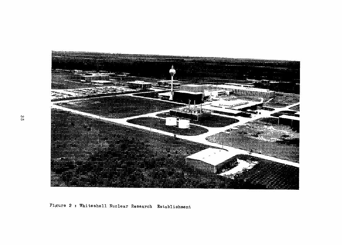
Figure 2 : Whiteshell Nuclear Research Establishment

In short, the purpose of this paper is to present a case studyof a nuclear institute designed to assist its country in reaping thebenefits of nuclear energy. The hope is that the experience and observa-tions will assist others in refining their own ideas on how the job shouldbe done.
HISTORY
By 1958, it was becoming apparent to us that the technicalfoundation for the Canadian nuclear program required considerable expan-sion if indeed we were serious about developing a Canadian nuclear in-dustry. At that time the Canadian effort concentrated at Chalk Riverwas more than a full order of magnitude smaller than that of the U.K.or the U.S.A.
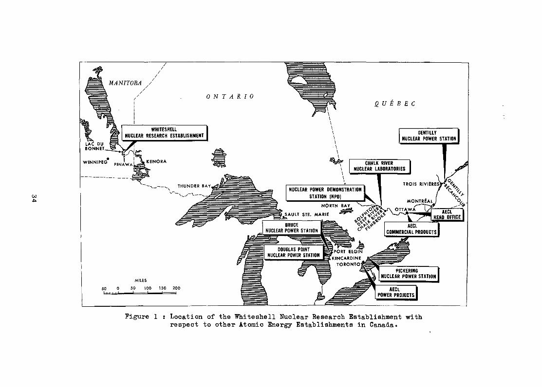
Through liaison with our foreign colleagues, we became awareof the concept of optimum size of scientific laboratories. It was apparentthat in laboratories above a given size, the vital informal communicationamongst the staff suffered considerably. How big is too big is probablya matter of subjective judgment. In the Canadian case we decided thatsomething in the order of 2500 was near optimum, and that if any furtherexpansion was to take place, it should be centered at another site. Thesiting then became a matter of political decision involving an equitabledistribution of federal funding across the country. Manitoba was certainlya defensible choice and the particular siting within Manitoba wasdetermined by the closest supply of clean water to a major community. TheFederal Cabinet decision to proceed with Whiteshell was made in October,1959.
Figure 1 shows the location of WNRE and Figure 2 is a recentaerial photograph.
When I arrived at Whiteshell in January 1966, the totallaboratory staff stood at 400; much of the physical plant was in placeand it was time to look for a more specific purpose and plan of development.
HCW DOES ONE GO ABOUT DEVELOPING AN ISOLATED TECHNICAL COMMUNITY?
There are three basic and self-evident steps which one mustgo through:
(1) Design the program.(2) Design the staff.(3) Design the facilities and environment to keep the staff
and execute the program.
36
Design of Program
Obviously, the program must be scientifically, technologicallyand economically defensible. If it is publicly funded, it must also bepolitically defensible.
The program can be designed such that the laboratory becomesa factory to produce projects worth executing or, alternatively, afactory to execute projects. In my view, an equitable balance should bestruck. The two approaches can proiit considerably by association:
(1) A program based entirely on evolving technologies which pro-duce worthy projects offers the advantage of continuity butlacks the more apparent benchmarks of success needed tosolicit continuing support. On the other hand, a programbased on executing a specific project (mission-oriented) iseasier to direct and organize. It offers easily recognizedachievements. However, it is much more vulnerable touninformed decision.
(2) Those engaged in the pursuit of exposing new technologiesbecome acquainted with the criteria of a good project andare better able to recognize opportunities which are exposedby each advance. Conversely, the mission-oriented staffhave a reservoir of critical expertize to tap when confrontedby tough obstacles.
At WNRE, we have attempted to strike what we j"udge to be a reasonablebalance.
To define the targets of our program more specifically,we attempted to study the world nuclear scene with some perspective. Wefound that one of three considerations had dominated all of the significantprograms of nuclear power development:
Capital CostEfficiencyNeutron Economy.
In the case of the U.S. enriched uranium light water reactorprogram, the high private utility interest rates and the ready availa-bility of enrichment focused the early program on capital cost. Efficiencyand neutron economy became secondary considerations.
In contrast, the U.K. and French programs turned their focuson efficiency with neutron economy and capital cost given secondary con-sideration. Hence, we find the gas-cooled reactor has dominated theearly development in these countries.
In the case of Canada, largely through the remarkable insightof Dr. W.B. Lewis, we adopted neutron economy as our religion and naturaluranium as our discipline. It was clearly apparent that the principal
37
asset which nuclear power had to offer was cheap fuel. If a competitiveedge was to be won, it had to be won on neutron economy. The bet was thatmost of the capital was tied up with transporting heat and that theenormous scope for engineering, manufacturing, and construction ingenuitywould level cut the capital costs of most systems to a common asymptote.This judgment has proved to be well founded. The most recent tenders andestimates indicated that the capital costs of all three systems fallwithin a band of about ± 10%.
Mow that the proponents of all three points of emphasis hâveestablished a commercially /irblc irr,'.is trial position, they are turningtheir attention to the previously neglected fundamental points of economy.Hence we find that the U.S. development programs are now focused on theneutron economy and efficiency promised by the liquid-metal-cooled fastbreeder. Similarly, the U.K. is looking to the fast breeder to retainefficiency and achieve improvements in neutron economy.
In the face of these observations it seemed both reasonableand important that having established neutron economy, the proper focusfor improvement in the Canadian system was the next target of funda-mental importance, i.e. efficiency» It satisfies all of the criteriamentioned previously. The fundamental barrier to the attainment ofhigher efficiencies is imposed by the lack of materials with sufficientlylow thermal neutron capture cross section capable of performing at hightemperatures. We have, therefore, adopted as the central technologicaltheme for WNRE, the science and engineering of high temperature nuclearmaterials and systems.
The first project which has emerged from our high efficiencyprogram is the organic-cooled version of the CANDU concept. This ishighly appropriate for WNRE. Our principal irradiation facility isWR-1, (Figure 3), a 40 MN reactor which we have been operating withremarkable success since November 1965. WR-1 is cooled with a low vapourpressure partially hydrogenatéd terphenyl coolant. This allows us toachieve high temperatures in the coolant system without the disadvantageof high pressures. The water-cooled systems in operation today areoperating at coolant temperatures of 300 C or below. In WR-1 we haveoperated for prolonged periods at 375 C and are currently operating witha coolant outlet temperature of 400°C. WR-1 has proved to be a tremen-dously valuaule facility in that mos- of the developments from thisprogram also find application in our vvater-cooled systems. This givesus a highly desirable and easily defensible basis of continuity.
Another project which has fallen out of our chemicalengineering activity is the development of a process uniquely suited toextracting plutonium values from our spent natural uranium fuel,s. - We.are engaged in a limited program of laboratory and engineering studies todetermine technical and economic feasibility. If these continue to beencouraging we will likely expand our effort and invite, private industrialparticipation. .•
We have examined in some detail th.e problem of producing smallpower sources and discarded this as a project on the grounds that thedevelopment cost cannot be justified by the low probability of commercialsuccess. .
38
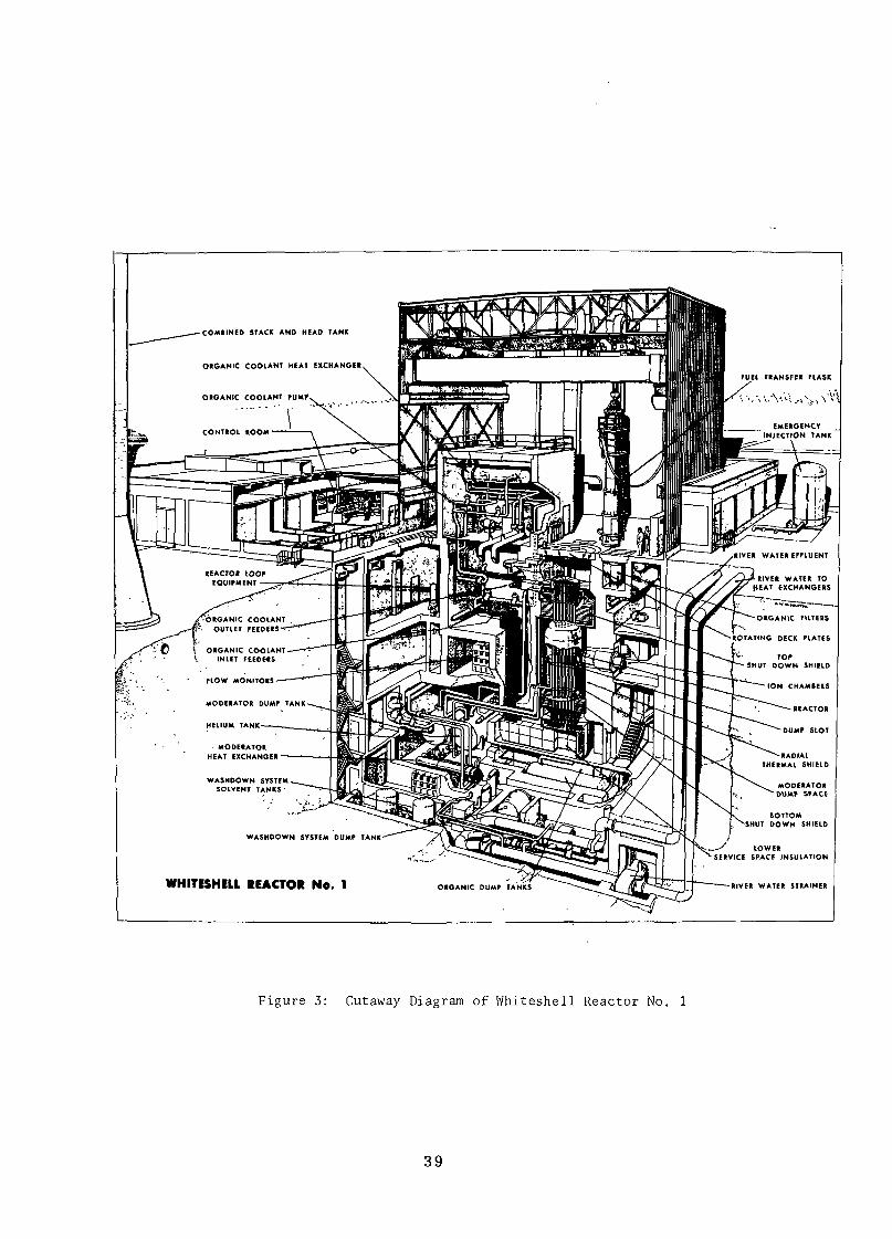
FLOW MONITORS
MODERATOR DUMP TANK
HELIUM TANK
WHITESHELL REACTOR No. 1
Figure 3: Cutaway Diagram of Whiteshell Reactor No. 1
39
In addition to the activities I have already mentioned, wefeel obligated to engage in some more fundamental research activitiesof a type which finds a particularly friendly environment at WNRE.Medical biophysics, ecology, and radiation chemistry fall into thiscategory.
Design of Staff, Facilities and Environment
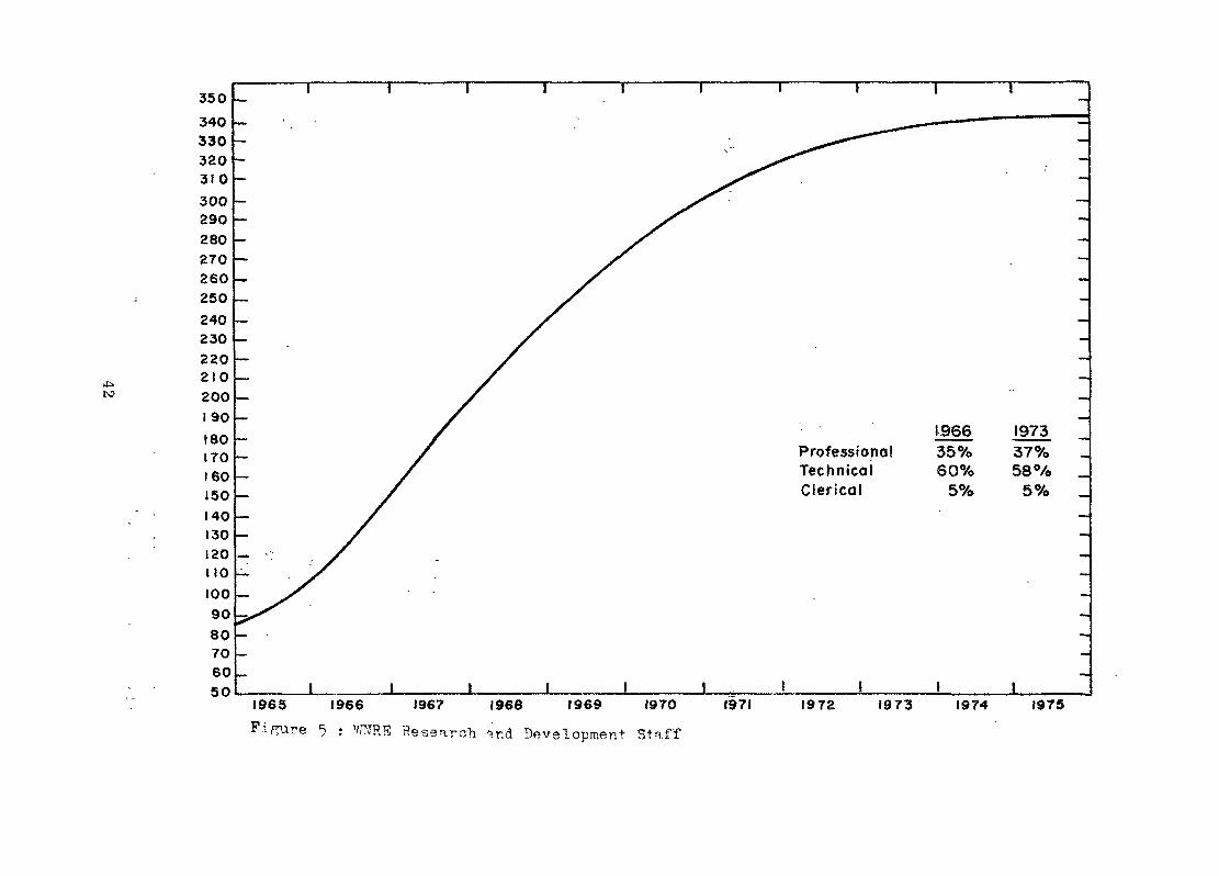
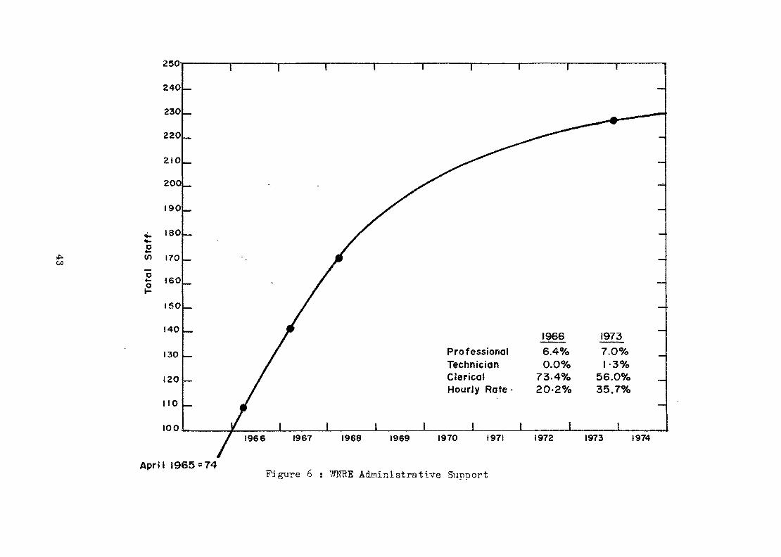
Having defined our general technical program, our next stepwas to reduce the program to the logistics of staff, support, budget, etc.required to produce a viable establishment. Figures 4, 5, 6, 7 and 8were prepared for my presentation to our Board of Directors back in 1966and will give you an indication of how we went about planning our growthand what we believe is required to produce an efficient and productivelaboratory.
OPERATION
A Molti-disciplinary, Multi-functional Institute
That a laboratory profits by interdisciplinary intercourseis now commonly accepted. That it can profit greatly by being multi-functional is a more novel idea. Many of us attribute the rapid in-dustrialization of nuclear energy to the introduction of this multi-functional characteristic. From its inception, the enforced intercoursebetween scientists and engineers has been a dominant feature of nuclearpower development. Historically, the scientist needed the engineer tocreate the irradiation environment in which to make the observationsnecessary for the next step in progress. It has been something of a leap-frog development, in which first the scientist and then the engineeroccupied the dominant position. The final step to commercial industrial-ization was made possible by the simple fact that engineers can communicatemore readily with industry than can scientists. This development ofmutual respect between nuclear scientists and nuclear engineers ispossibly the most important single asset of nuclear laboratories. Asfuture discoveries are made, the channel to productive application isalready open. This not only assists in creating a productive high moralein the institute, it also assists greatly in soliciting continuingfinancial support.
I would find it hard to believe that any laboratory isserious about applying its technology and assisting in the industrialgrowth of its country unless it were developed as a multi-functionalinstitute. At WNRE, we attempt to keep a balance between fundamentalscientists, applied scientists and engineers.
40
Project Assessment
We have come to regard project assessment a very importantpart of our activity and one which demands a great deal of experimentaland analytical effort. In point of fact, aside from the more fundamentalprograms we are engaged in, all of our activity can be related to thevarious steps of project assessment required to elevate an idea to thepoint of industrial application.
One of the important weaknesses often noted in the researchcommunity is that:
(a) It has generally failed to appreciate the size andimportance of the job of assessing projects; and
(b) It often lacks the machinery to coordinate the manydisciplines and functions needed to realisticallyconvert ideas -into projects and to select those worthyof expanded attention.
RESEARCH
1.2.3.4.5.
Radiation ChemistryMaterial PhysicsPhysical § Inorganic ChemistryMetallurgy and CeramicsMedical Biophysics
PROFESSIONAL 'STAFF ONLYJune 1966 Required
5 8-100 8-101 8-101 8-103 10-12
DEVELOPMENT
1.2.3.4.
5.6.
Applied Metallurgy 4Fuel Development 6Chemical Technology (Chem. Eng.) 6Future Projects Evaluation and Applied 3Mathematics
,'Analytical Chemistry 5Electronics, Instrumentation Control 1and $on Destructive TestingComponents Development 4
• f
TOTAL 39
10-128-10
10-148-10
10-1212-14
10-12
110-136
Figure 4: Research and Development Staff to Meet Whiteshell Objectives
41
to
196635%60%
5%
ProfessionalTechnicalClerical
1965 1966 1967 1966 1969 1970 1971
Fippare •? : W.E Hesearoh ir.d Development Staff
1972 1973 1974 1975
co
250-
240
230
220
210
2OO
190
4. ISOn-£en (70
f 160
150
140
130
120
110
100-
April 1965 = 74
ProfessionalTechnicianClericalHourJy Rate •
19666.4%0.0%
73.4%20-2%
19737.O%1-3%
56.0%35.7%
1966 1967 1968 1969 1970 1971 1972 1973 1974
Figure 6 : W5TRE Administrative Support
800
700
600H-
^
5) 500
"5«»° 400
300
200
100
ProfessionaltechnicianClericalHourly Rate
1966 197317.0% IE. 2%14.7% 16.8%16.5% 9.6%51.6% 61.4%
I&65 1966 1967 1968 1969 1970 1971 1972 1973 1974 1975
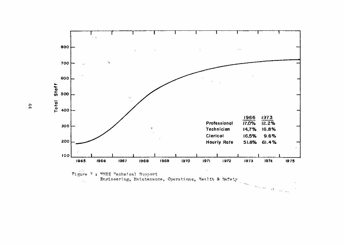
Figure 7 : '"rNR13 Teohn1cal SupportEngineering, Maintenance, Operations, Health & Safely
en
I4OO
1300
1200
1100
1000
900
800
1- 700o4-
W 600
300
400
300
200
100
0
Recommended Establishment for 1967-68*825
•WNRE Approved Establishment» 626
ProfessionalTechnicianClericalHourly Rate
Whiteshel!1966 1973
19.3% 18%22,2% 25%27. 7% I 7%3O.8% 41%
Chalk River1966
18%20%18%44%
1965 1966 1967 1968 1969 I97O 197! 1972 1973 1974
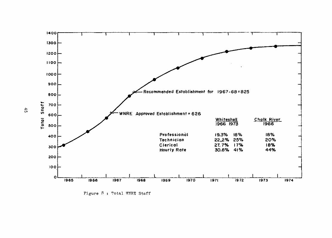
Figure 8 : Total WNRS Staff

As a result, many projects emerge poorly conceived and either die-atbirth or fail to mature.
Throughout the world, research is an activity which inevitablytaxes the public purse. At the level empirically known to be necessary,it requires predominantly public patronage, not private. It is thereforenecessary to distinguish between the motivation of the person engage'd inthe activity and the public who are paying for it.
As for the scientist, the best of the workers are motivated bythe highest philosophic principles - the search for truth, and the creationof symmetry, understanding, order and beauty. In short, the motivationis more cultural than utilitarian. Those who constitute the large bodyof average scientists are driven by the vision, if not its fulfillment.
the public, on the other hand, believe they are making aninvestment in the future. They support research because they know-itto be a'necessary ingredient of progress. They look to its directorsto insure that their research serves this function.
The smaller the resources of a nation, the more importantit becomes to recognize the need for cultivating a philosophy of»'a broadoutlook and focused application on the most promising lines of attack.The formality of establishing a discrete organization to conduct thisreview function is a discipline which helps an institute to foster thecorrect philosophy. At WNRE we use a small nucleus of people to performthis function. For the assessment of any given project, experts aredrawn from throughout the laboratory organization.
External Domestic Contacts
Part of the unwritten mandate of such a laboratory is tostrengthen the technical community of the country it hopes to serve.At Whiteshell we associate closely with the universities, consultantsand private industry to our mutual advantage. Because of our proximity,it is natural that our relations with the University of Manitoba areparticularly strong. For example, we have a private link to the Universitycomputer. Some of our staff are appointed honorary professors, privilegedto lecture and accept graduate students with no pay. We have researchcontracts with appropriate departments of universities in all of theCanadian western provinces. 4
With regard to our industrial contracts, we find that thelaboratory staff and industrial staff work most profitably as a team,attacking different facets of a common problem. This is best done byplacing the administration and direction of the contract under a technicalman actually working on the project himself. He is not only morequalified to give technical direction, but even more important, hecommands the technical respect of his colleagues in industry.
By trial and error, we have found that. the.optimum number ofindustrial professionals that can be directed by one laboratory pro-fessional is four to five. If he is called on to direct more than thisnumber, he either neglects his own work or cannot follow the work of hisindustrial colleagues in sufficient detail.
46
In the case of consultants, we try to use neighbouring talentwherever possible, even if we anticipate some learning loss. Distanceproves a formidable barrier to communication.
This intercourse with the external community is not onlypolitically sensible, it is also technically sensible in that thelaboratory is continually exposed to new perspectives and ideas.
Scientists as Executives
I do not endorse the idea that scientists should be shieldedfrom the logistic and management problems associated with a laboratory.At Whiteshell they are held responsible for their internal administrationand financial control and are expected to develop their executivepotential as well as their technical potential. It is no secret that thecreative energy of man decreases with age. The older and more seniorscientists have much to contribute as technical management after the 'firstsurge of creative research has passed. It is wasteful of such talent notto prepare it properly for this important future function. If WNREproduced nothing more than candidates trained to direct future Canadianlaboratories, Ï would feel that we had made an important contribution tothe progress of our country.
Financial Performance
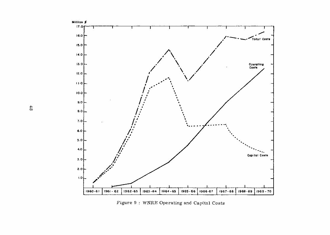
Figures 9 and 10 give the financial history of the projectas a whole. The following points are noteworthy:
(a) Capital for conventional laboratory buildings and servicescan be spent rather quickly and peaks in the first fewyears.
(b) Contrary to lay opinion, significant capital resources arerequired annually throughout the history of the laboratory ifit is to carry programs through to the engineering stage ofdevelopment. While most politicians are familiar with theconcept of spending money on buildings, they are less awareof the critical continuing need to keep equipment updated andto provide facilities required by engineering programs.
(c) Taking escalation into account, operating costs are closelyrelated to the numbers of employees and run at an averageof about $18,000 (U.S.) per man-year.
We in Canada lay great stress on the importance of in-pi leloop facilities in which both fundamental and applied experiments canbe carried on under irradiation. Indeed, we would claim that withoutsuch facilities it would have been impossible to achieve the developmentof the CANDU reactor concept with so modest an effort.
47
oo
Million17.0
16.0
15.0
14.0
13.0
12.0
I 1-0
10-0
9.0
8.0
7.0
6.0
5.0
4.0
3.0
2.0
1.0
.-"^To ta I Costs
I1960-61 1961-62 1962-63 1963-64 1964-65 1965-66 1966-6? 1967-68 1968-69 1969-70
I
Operating —Costs
Capitol Costs
I
Figure 9 : WNRE Operating and Capital Costs
tf».CO
2.0 -
1.0 -
ProjectedYearlyOperatingCosts of?2IMillionby 1975-76
Total -Operating
Costs
Total CapitalCosts
BuildingServices
Equipment
LoopsMajor Loops
P-"'1 9 6 0 - 6 1 1961 - 62 1962-63 1963-64 1964-65 1965- 66 1966-67 1967-68 1968-69 1969-70
Figure 10 : MRE Operating Costs and Break-down of Capital Costs
Months
Preliminary Planning
AECL Specs.Detail SpecsContracted OutTendering
Construct ion
Commissioning
4Months
5 Months
10 II 12 13 14 15 IS 17 18 19 20 21 22
13 Months
2324 25 2<lz72e 29 3031 32 33 34353837 38 394041 4243 44 48484748
f> Revisions4 Months 1
| 18 Months
4 Months
Major Modifications During First 3 Years Not Included
A c c u m u l o t e dCost (,000)?
1000
900
800
700
600
500
400
300
aoo100
0
Month
T o t a l O u t s i d e Design, Cons t ruc t i on , Ma te r ia l Cost - 9 997,060.Excludes W N R E Design and Commiss ion ing Costs est. at #125,000.
—w^*" ——— . ———— ——— •——|_ ————— -"-
•MM
0 II 12 13 14 15 IS 17 18 IS 2O 21 22
/— s*:=
2324 2528 2728 29 3O 31 32 3334 353837 38 39 4041 424344454847 48
Figure 11: 1L2 In-reactor Pressurised Water and Boiling Water Loop -Schedule and Sumnary of Outside Design, Construction andMaterial Costs.
Month
Prel iminary Planning/Design
Detail Design/Specs.-ContractedOut
Construction by WNRE Forces
1 2 3 4 5 6 7 8 9 10 II 12 13 14
6 Months
8 Months
15 16 17 18 19 20 21 22|23 24 25 26 27 28 29 30
13 Months
Months I
A c c u m u l a t e dCosts (,000) 9
250
200
175
150
125
100
75
50
25
0
Month 1 2 3 4 5 6 7 8 9 10 II 12 13 14 15 16 17 18 19 20 21 22 23 24 25 26 27 26 29 30
Figure 12: RD-5 Out-o£-Pile Water LoopSchedule and Summary of Construction, Material and Design Costs.
I felt it would be useful to present the financial and schedulinghistory of two such projects which are typical of several that we haveexecuted. One is a major in-pile facility, 112, (see Figure 11) andthe other is a more modest cut-pile supporting facility, RD-S (seeFigure 12). The point I wish to make is that it requires a surprisingamount of capital, planning, and time to carry on such projects fromconception to execution. It stresses once again the importance ofplanning in the management of such programs.
SOME OBSERVATIONS AND OPINIONS WHICH MAY BE OF INTEREST
(1) At WNRE, 15% of the professional staff have had physicstraining of one kind or another. At CRNL, the number is 22%.It appears that physicists are no more able to make theircontribution in isolation than men from other disciplines.
(2) Thirty-five percent of the professional staff have Ph.Ds.Our history indicates that Ph.Ds have no greater nor lessprobability of organizational promotion than those with lowerdegrees.
(3) Scientists engaged in fundamental research like to beassociated with a laboratory which also has programs witha more clearly identifiable purpose. It is both a sourceof stimulation and security.
(4) I indicated earlier that we had not achieved our growthtarget. Even if we had not been restrained by our budget,it is doubtful that we could have grown any faster. Therestraint is not imposed by the supply of bright younggraduates, but rather by the supply of competent middleand senior staff with the combination of technical excell-ence and executive experience required to direct morejunior colleagues. From our experience at Whiteshell, Ifind it incredible that reputable individuals and organiza-tions believe it is possible to responsibly expandresearch capacity at rates in the order of 30% to 50% perannum. I could not endorse a growth rate much higher than20%.
(5) I cannot change my estimate of the size of operation neededfor a mature interfunctional, interdisciplinary, nuclearlaboratory (1200 to 1300 total staff). At our present 800we are barely "critical" and can identify many importanttasks which need attention.
(6) The Cabinet decision to launch WNRE was taken in 1959.I judge that we became a productive institution only withinthe last two years and that we will not be a fully matureoperation until about 1974 - some 15 years after thedecision to proceed.
52

Unless their performance is much better than ours, those nations whofeel they need nuclear power within the next 20 years could, with profit,begin vigorously building their laboratories today in order thatadequate technical support is available when needed.
Questions and/or Comments
The total annual budget for the Whiteshel Nuclear ResearchEstablishment is roughly between 16 and 17 million US dollars;this includes both operating and capital costs. It is easier toget financial support to build buildings than to equip them.
53
THE ORGANISATION AND FUNCTION OF DESIGN SERVICES
DEPARTMENT OF RESEARCH REACTORS DIVISION
byF. TaylorU . K . A . E . A .
Harwell, Didcot, Berks.
Abstract
The paper inc'J ca4-e.-. He r.'irr'b^r of staff ir.vol v°d , the or-ar.J. s-.,-
i,f;ea, gnc. the coMcieo a d o p t e d , i r. oarryjn*-: out the enf-ri^eer"5 r.r:- prc-
^•"a'nme^ necessary "i1" ^^pea^ch refictorr. at A . Z . R . E . in siir/;.o:r4' of thp
Since t?.e crpar.i -î"'1 r! O'r; a>'rî polio: sa are h«ped or Tiar.y year- 'a
ex^e.r: er.ce i4 " P SU;-"PEPF ted th-^t the inf ' i r^rj t lor is useful to r r r i c j l l e r
:ar;n °-^t"-or P. oser'it. "in;-1 Jr sini" 1 ?i- file's of endeavur.
INTRODUCTION
1• The provision of equipment for carrying out in-pile experimentspresents problems, sonxs of which can be solved by the application ofconventional engineering procedures, but the. rest are often unique. Itfollows that it is necessary to employ engineers in this field v;ho have'been trained in a convontionnl engineering manner by study and practicalexperience and have subsequently acquired specialised knowledge andexperience in nuclear-engineering netters.2» It raust be borne in mind that the equipment is being provided foruse by scientific staff whose requirements are very demanding sincethey invariably work at the limits of technology. Hence in order toprovide the effective and efficient service required much thought mustbe given to the set-up of the organisation in which the engineers areemployed.3. This note identifies some of the problems inherent in the provisionof in-pile equipment and indicates bcv,v Design Services Department isorganised so as to provide the service demanded of it.
55
THE PHILpSOFÎB? EMPLOYED IN SETTING UP DSSIC-H SEg/ICES .DEPAHTI.SMQ.'4. Since it is good management practice before setting up an organi-sation to establish clearly the objectives which have to be achieved thework area associated with Design Services Department was thoroughlyanalysed and the follov.-ing facts v/ere noted as being important.
(a) The department is a service organisation and must provide afirst-class service to its users.
(b) The users are scientists v?ho as a result of training andvocation demand precision and progress,
(c) A materials-testing reactor is not a precise machine owing tosuch matters as burn-up of fuel etc, and so the precisionrequired by the scientists must be provided for in the designof the equipment»
(d) The engineer (known as the Project Engineer) raust be responsiblefor all aspects of the work through the stages of design, manu-f&ctux'e, testing, and in-pile operation, and in addition thecompiling of the safety and operating documents. To carry outthis function he needs experience, intuition, imegination anddata.
(e) The data required must be kept under continuous review so as toensure that they are up-to-date end reliable.
(f) "Tools" œust be provided for assisting the Project Engineer toanalyse his design before the manufacturing stage is reached.This analysis is demanded.(i) by the need to conserve funds and meet specification,(ii) by safety aspects,(iii) to assist in evaluating results of the irradiation»
(g) The spectrum of v;ork is broad and involves a number o:' specialistsections, all of \vhora must be encouraged to provide porr.ir.entideas. '•
(g) Such ideas must be thorougîily discussed and evaluated. i(j) Worthwhile ideas raust be developed and put into use.
(k) lûore complex technical matters should be resolved by reference toa special section highly trained in academic procedures.
(l) Instrumentation forms a fundamental part of every experiment andadequate attention should be given to this frees the point of vie'wof (i) control (ii) safety of rig, reactor, and staff, '/
THE FAMILY TH3S
5* The department consists of approximately seventy professional/graduatestaff divided into a number of sections as follows.
56

(a) Five Design Sections each consisting of approximately eightProject Engineers and a Section Leader all producing equipmentfor a specialised area of work es indicated in Appendix 1.
(b) A section responsible for .all rig and reactor instrumentation -recorders, controls, warnings, and trips»
(c) A section responsible for technical assessments.(d) A section responsible for .esting end commissioning of all in-
pile equipment ana instrumentation and also for development work.(e) A Design Office.
fflg_FUljCTION OF A DBSI&N SECTIONb. Each Project Engineer in a Design Section is responsible for a numberof in~pile assemblies (nomclly not more than five) and must carry completeresponsibility for the whole job from the first feasibility study throughthe stages of design study, detail design, développent, manufacture, inspec-tion, testing, and commissioning to the first period of in-pile operation,Ho do this adequately he rauut supervise junior staff within the departmentand also at contractors, and must liaise very closely with the scientist(knovm as the user) concerned at all stages» In addition he is responsiblefor the papers which are presented to the Safety Committee for approval(before irradiation is begun) and also for the operating documents.7. A number of Project Engineers report to a Section Leader, who carriesoverall responsibility for technical, financial, and administrative controlof his section and also is regarded as having.sufficient knowledge of hisusers' requirements to be able to assist in planning the work load anddeciding policy matters relative to his section and the department.
TH3 FUNCTION OF TrJS IKSTEULSÏ.TATIOX8. Ins!,ru-T.s.vts.t:j.ori força a very irr.:.crt-nt rurt of all In-pilc? e:ci.jri-".c-nts,since the importent parameters must be recorded for use in the «evaluationof results, the experiments must operate within precise conditions, andv,-&rnings and trips are a necessary feature of safety aspects. To meet thisrequirement the section designs and produces an individual system for eachexperiment and carries out any development work necessary.
The section also provides a service to the Reactor Manager relativeto instrumentation requirements.
THE FUNCTION OF TESTING AND CO;nS3IOin:K& SECTION9. Although a part of the Design Services Department, Testing andCoamissionirig Section has a primary responsibility to the Reactor Managersince it must assure him that a piece of equipment has beon thoroughlytested and is safe to operate in Ms reactor. It also poi-forms the func-tion of recording the faults found in new assemblies before irradiationcommences and of failures in-pile cue to component faults, This infor-mation is fed back to the Project Engineers in order to ensureincreasingly higher standards. The section is responsible in addition tothe above for the development of new components and techniques pertinentto the work of the department,
57

EATURES OF THE OBSAICTSATION OF D55IGN SBRVICES DSPARK.SNT10. Reference has already been made to the philosophy which was employedin setting up .Design Services Department. Experience gained during recentyears has shown that philosophy to have been correct. Listed below arecertain features which are seen to be of paramount importance since with-out them it would not have been possible to satisfy the requirements ofusers, management, and Project Engineers.11. Nuclear-heating data (e.g. gamma heating) have been obtained, and arecurrently obtained, "by means of cal ,rimetry carried out every reactorcycle in selected positions„12. Flux data are obtained v/herevcr possible by the use of continuousmonitors installed in experiments and individual readings in mock-up rigs.13» The data are sent to a central point where they are processed, andinformation is then issued to all members of the department,14« A service has been provided for producing electrical analogues (bothtwo-dimensional and three-dimensional) in which temperature gradients inspecimens are established. Two-dimensional and three-dimensional computerprograms are also available for this work.15» Results obtained from experiments operating in-pile are sent back tothe central source mentioned earlier, and are analysed and added to theother accumulated data which are available to Project Engineers as designdata.16. Each section holds meetings at intervals to discuss the collectivetechnical problems in its field, and any proposals made are submitted to ameeting of the Section Leaders for agreement and support.17. In addition to Section Meetings certain Study Groups also exist forthe following matters
Creep Keasurer^ntHeater Design and TestirigTemperature Measurement and ControlDesign Data Requirements.
Each Study Group consists of users as well as Project Engineers, andprogrammes of work are carried out with their agreement in a fullyco-ordinated manner in the subjects stated.I8e Section Leader L'.eetings are held at which technical, financial andadministrative policy matters are discussed and referred to the DivisionHead for approval,
CONCLUSIONS19» The Design Services Department has been operating for some 3rearsalong the lines indicated, and experience has shown that with very littlealteration to the existing pattern major changes in work requirements canbe provided for»
58
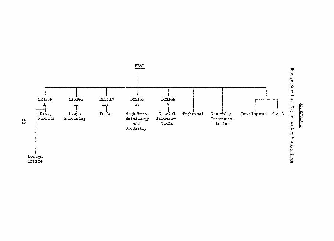
EBAD
CO
DÏÏSI&N DESIG-W DESIGN DESIGN DESIGN i ——— ' ——— iI II III 17 Vi
Des
— • ' "•• 1
Creep Loops Fuels High Tesp. Special Technical Control & Development T & CRabbits Shielding Metallurgy Irradia— Instrumen-
and tions tationChemistry
ignOffice
Design S<
IL>
'r1-O<D01
CDV>
8o
%£03-
ÏCD
15i)PXM
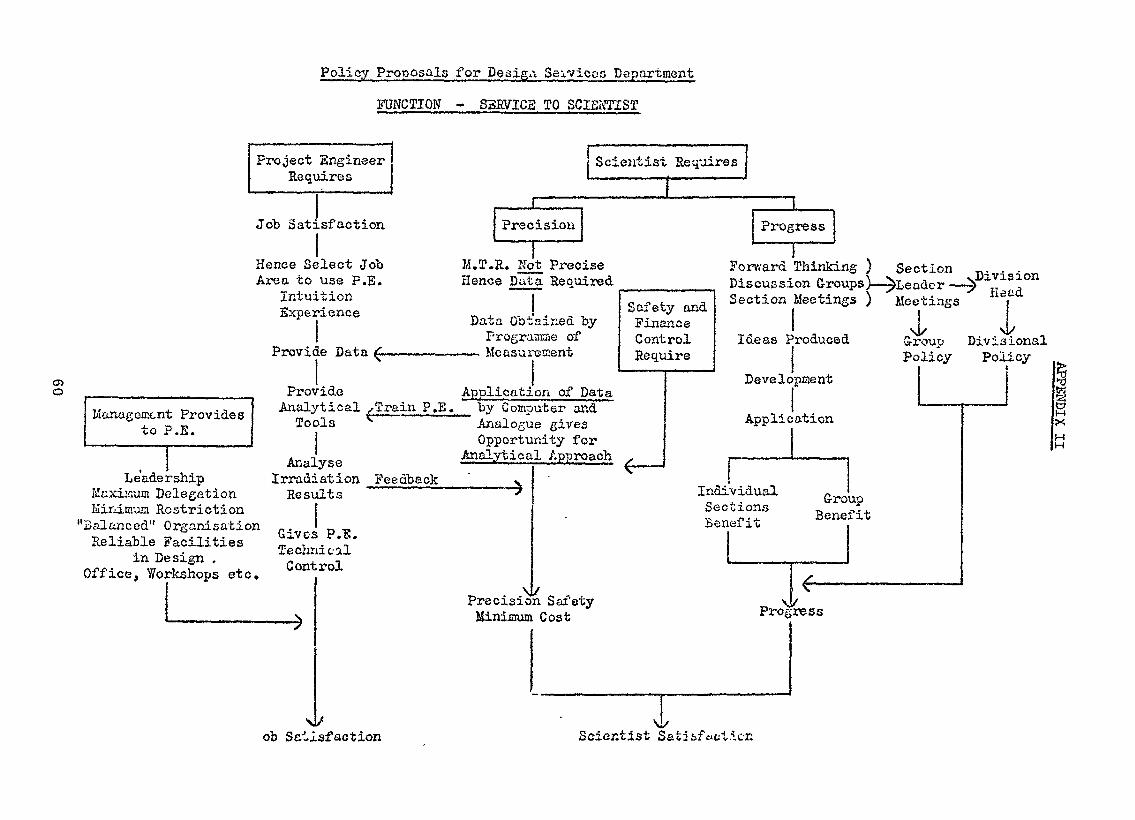
Policy Proposals for Desiga Services DepartmentFUNCTION - S3RVIC2 TO SCIENTIST
Cio
Project EngineerRequires
Scientist Requires
Job Satisfaction
Hence Select JobArea to use F.E.
M.T.R. Not PreciseHence Data Required
Forward Thinking )Discussion
Section
Management Providesto P.E.
Le'adeMaxiiaum DMinimum R
Balanced" (Reliable 3
in DeOffice, Yfoj
Intu:Expej
Provit
Pro;Anal^
Tot
Analrship Irrad:slegation ResvsstrictionOrganisation „ .-, .,..,.. Gives?acilities „. ,Techrïsxgn ' Contrkshops etc. ^
v/
V
ttion?ience _ .Data Obt
Prograle Data ^ ————————— Measui
ride Applicati
Safetysined by FinanLinae of Contrornent Re qui
on of Datartical xTrain P.E. by Computer andxls Analogue gives
Opportunity for„_„ Analytical Approach ..ysw ""• — UJ1^ — - ——.ation Feedback " vat s '
\ P.Ï.dealrol
PrecisicMinimum
f
--" ~ ^ —— '
n SafetyCost
, Sectionandceol Ideas ïre
Develc
Applic
Meetings ) Mee
^reduced G-iPc
'pfflent
:ation
Individual -,n j. • tr*"0Sections ^Benefit Bene
Pro)
.i \/ress
upfit
, . ' Weutttings i
1- » - - i i•oup Divisionallicy Policy
t^f
M
}-tH
ob Satisfaction Scientist
Questions and/or Comments
If one would take your organization new, "being focussedentirely on the service of scientists and scientific experiments,and it was asked to design a power reactor, what additional talentswould you need ?
My own personal conclusion is that you csnnot start designinga power reactor with people who have only had experience in thein-pi le research reactor field, dealing specifically with experiments,one must also have reactor engineering experience. In fact, work or,research reactors is very necessary, but it must be followed toy anintermediate stage before going into the power reactor design itselft
It was pointed out that in order to succeed with irradiationexperiments, whatever they may be, it is necessary to follow theexperiment's behaviour during irradiation and. whatever the previousstudies might have been, one learns at least as much, 4f not more,as if one would observe during the time the experiment in beingperf orrred.
61
STATUS REPORT OF THE ENGINEERING PROGRAMMES
AT THE BEACTQR CENTER SEIBEHSBOfiF, AUSTRIA
byA. Burtscher
Oestarreichische Studiengeaellsehaftfilr Atomenergie snbH.
Reactor Center Seibersdorf
A revj ev/ of the engineer. i i^c r-Torrmnrr.Ks is ^j ver, v /MoVi arepd out at t>. « AS'TRA le&ictor1. Further, thooe ï:3'o^;ramtr,€v--, are
l i s ted which are irade ir coopéra t iori /v l t l : th*3 /ut; t r ia ;< indu
at the research certer.
INTRODUCTION
The Reactor Center Seîbersdorf of the Austrian Atomfc Energy ResearchOrganisation Is located 30 km south of Vienna. The aim of this reactorcenter Is the basic and applied research In the field of peacefulatomic energy In close cooperation with the Austrian state, theIndustry and the universities. The research organisation also Isentrusted to carry out special orders in the field of atomic energyon behalf of the Austrian government.
The reactor center comprises the research reactor ASTRA and the laborato-ries for physics, metallurgy, chemistry, reactor technology, electronics,biology, health physics,and a laboratory for the application of radio-Isotopes In Industry. Presently, about 400 people are employed at thereactor center, 20 % of which are scientists and engineers.
Tbe ASTRA Is a pool type research reactor which Is operated up to 7,5 MW.The experimental facilities consist of ÎO beam tubes and of a largenumber of Irradiation positions In fuel elements, In the core and Inthe beryllium- and the water-reflector for the Irradiation of samplesand Instrumented capsules» Adjacent to the reactor Is a hot ceil forthe dismantling of the Irradiated experiments.
63
ENGINEERING PROGRAMMES AT THE ASTRA-REACTOR
The Engineering Programmes at the ASTRA reactor can be devfded Intotwo categories:
te Programmas concerning modifications of the reactor2. Programmes for experiments at the reactor
The programmes for reactor modifications are mainly small engineeringprogrammes arising from the experimenter's wish to get better experimentalconditions.
Examples for such programmes are: Increase of the reactor power levelcr installation of a better reflector Into the ASTRA reactor In orderto got better thermalIzed neutron for the beam tubes. These programmesaro normally carried out from the operations group of the reactor,and, If special problems arise, specialists from other laboratoriesas metallurgy, chemistry or from the computer groups are consulted.
With respect to reactor experiments on the beam tubes, some of themrepresent real engineering programmes, requiring a skilled teamcomposed of several different disciplines. As an example, I wishto mention the beam tube-experiment for the measurement of theangular correlation of the electron-neutrino which Is one of thebasic parameters of weak interactions. This experiment required afew years for the design, manufacture and testing. The main problemswsre the required ultra high vacuum under Irradiation conditions andthe design of the large electrostatic spherical condenser energyspectrometer (30 cm 0, 6 cm electrode distance) used for the measure-ment of the proton spectrum. AI I these experiments and programmeswhich are made in connection with reactor modifications or with basicresearch experiments, do actually not fit directly Into the scopeof rthfis panel, since there Is no direct connection with the nuclearpower programme of the country.
One of the engineering programmes of the reactor center Seibersdorfwhich fits better into the scope of this panel Is the developmentand testing of fuel particles for high temperature reactors.
64
This programme had been started already 10 years ago and It was Ini-tiated as a result of Austria's participation on the OECO HighTemperature Reactor Project DRAGON. Thîs project Is a collaborationbetween the laboratories of chemistry„ metallurgy, physics and theASTRA reactor, ft comprises the production of spherical fuel particlesby metallurgical and chemical methods, the coating of these particleswith pyrocarbon In a fluidized bed and the testing of this fuelparticles before, during and after Irradiation. For the burnup testsof this fuel In the ASTRA reactor, discontinue,.^Iy purged capsuleshad been developed for fuel temperatures up to 1500 °C« A numberof such capsules were irradiated în the ASTRA reactor up to 4000hours, resulting in a fuel burnup of 30 %t The release of xenon-,krypton- and lodfne fission products was measured with the disconti-nuous purge system. The irradiated capsules were dismantled and thehighly active fuel was sent from the reactor to the metallurgy- andchemistry laboratory for postIrradiâtIon analysis.
For these type of experiments, not only the burnup achieved duringirradiation in the research reactor Is of primary importance buta(so the fast neutron fluence. When the specifications called for
21 2fluence values a few times of to n/cm , these irradiationexperiments had to be stopped at the ASTRA.
With respect to material testing, facilities for the irradiation ofsteel specimens at various temperatures with fast neutrons and for thetesting of the Irradiated steel have been devetopped. However, wecould not quite convince the steel industry from the necessity ofsuch experiments In view of the possibilities to produce stee! forpressure vessels and core components. Therefore, not full use fs madefrom these irradiation facilities for steel specimens.
ENGINEERING'PROGRAMMES AT THE REACTOR CENTER SEfBERSDQRP OUTSIDETHE ASTRA REACTOR
There are a few large engineering programmes In the reactor centerSelbersdorf which were initiated with the purpose to make Austriancompanies familiar with special features of reactor components and
65
thereby threngthen their position as subcontractors for nuclear powerplants.
One of these programmes was the design and construction of a flexibleexperimental waste water treatment plant for power reactors whichallowed the detailed study of the different phases of the water puri-fication, e.g., the evaporation for the concentration of the activeImpurities or the storage of the active residue In bh-umfnous sub-stances.
An other large scale project In the field of fluid metal technologyIs a sodium loop which can be operated at sodium temperatures up to800 °C. This loop was built In close cooperation with an Austriansteel manufacturer for the purpose to develop and test componentsfor fast breeder reactors. The sodium loop Is also operated forother research organisations and companies concerned with the develop-ment of fast breeders on the basts of a research contract.
In connection with the OECD heavy water boiling reactor project InHa Iden/Norway, a boiling water loop has been designed and builtwhich enables the study of shortttme phenomena In a boiling waterreactor directly after a change of the operation conditions. Theknowledge of such phenomena Is Important with respect to the optimallayout and with respect to the safety of boiling water reactors.
A further project which has recentI been started at the reactor centerSelbersdorf moves Into the field of High Temperature Reactors. It Isplanned to gain experience In the design and construction of pre-stressed concrete pressure veèsels and of components used In thehigh temperature helium circuit. With this project It was possibleto sttmulate the Interest of the Austrian Industry and. In fact,the largest steel- and construction companies are actively partici-pating.
It has to be determined whether the ASTRA reactor with Its Irradiationfacilities can be usefully Incorporated In the above project. Prelimi-nary Irradiations of steel rods embedded In concrete showed that
66

Important results can be obtained by capsule Irradiations. It seemstherefore that the panel might also consider such engineering program-mes which are not directly Installed In research reactors, especially,because difficulties often occur in the so called conventional partof nuclear power plants.
Questions and/or Comments
What is the time period between Austria's position now and atthe beginning of the installation of nuclear power ?
This cannot easily be predicted since it depends on economicjustifications and Austria's nuclear power will not be set up bythe Government but by the private industry.
Major investments appear to be m?de in developing the capacityto produce nuclear scientists and engineers. Is there a clear ideaof how the country itself is going to profit by the education ofsuch trained people ?
In principle, it is not felt right to limit the educationalresources in the nuclear field just because there is no directpOFsibility to keep the trained people in the country.
This abovementioned important point was brought up; i.e.how one could frame engineering programmes so that they would infact employ the manpower ' Perhaps 3t may be too soon to developsuch programmes now so that they will come to fruition ai the timethey are needed and meanwhile the manpower is being used, developedand trained for the long-term good of the country concerned.
is the industry's reaction to its involvement in engineeringprogrammes at your nuclear reactor research center ' Whenever onetries to raise the interest of industry, industry will always considerits participation on the basis of a possible return or profit to begained from such participation.
How much is industry interested in contributing financiallyto your private organisation for this sort of engineering research ?
67

The interest of Austrian industry ir. Seibersdorf was very greatin the beginning and they contributed significantly in order to financethe building of the Center, then there was some time when the optimismwas reduced, and now we are trying to raise the interest of theindustries by consulting them about what are the possibilities, whatcan Austrian industries do with respect to the increasing number ofnuclear reactors being built ? So, our task would be to selectprogrammes which will have some future in the next years, and ifwe can convince industry that these programmes will be worthwhile,T think they would not mind to contribute with manpower, withdelivered components, or designs done ir. their own facilities.Again this depends on what is the future profit to be expected -,and industry always sees money in the foreground.
A comment was made regarding the fact of being able to getindustry to invest in institutions rather than institutions toinvest in indirstry. Generally, when industrial participation isneeded, the institutions give contracts to industry to help themcome along. In this case, having succeeded to get any support fromindustry means that the Seibersdorf Center is certainly facing avery enlightened group.
68
A BRIEF NOTE OFTHS USB OP RESEARCH REACTORS AT A.E.R.E.
byP. TaylorU.K.A.5.A.
Harwell, Mdoot, Berks.
AbstractS5ÎSÏC:=ÏEa:=sfi:=
The U.K. power programme has been discussed in many recenttechnical papers and journals. A programme of this magnitude de-mands a supporting programme which must "be carried out in availableresearch reactors. This supporting programme covers a broad complexspectrum of work.
The paper to be presented indicates briefly the research reactorsbeing used, the work load involved, staffing requirements, and com-parative costs.
Introduction1. The development of nuclear reactors in the United Kingdom has been aimedfrom its earliest days at producing power from thermal reactors more economi-cally than from conventional-fuel type stations and at the same time producingplutonium in order to obtain the economic advantages offered by the fastreactor. This aim has meant investment of large sums of money and the employ-ment of a large experienced labour force in this rather specialised field.An analysis has shown however that the benefits to be gained from thecontinued development are around ten times the cost of the development*2. The degree of success in achieving the stated objectives can be judgedby the facts that more than 5000 W(e) of nuclear power are operational atpresent, this will be doubled by 1975, and sufficient confidence exists inthe United Kingdom to proceed as rapidly as possible with the construction ofthe Prototype Fast fieactor of 250 îW(e) capacity. Mention should also bemade of the successful operation of the S.&,H,W.E. as an alternative to thegas-cooled reactor.3. To take an almost unknown technology and develop it as broadly and asquickly as has been done in the United Kingdom is no mean achievement, and itcan justifiably be claimed that the Materials-Testing Reactors at A.EJl.E»and D.E.R.E. have played an important part in the process»
69

Research Reactors Within, the IJ.Kj.A.^.A^ (Thermal Reactors Only)
\+» In order to achieve the aim referred to above the U.K.A.E.A. hasprovided over the years a number of research reactors of different types, allof Vihich have been heavily committed. These reactors are listed brieflybelow.
GljSgP - Pov<e_r 50 k?/Used mainly at present for measurements relating to the nuclear cross-sectionsof materials used in reactor construction.
BEPO - Power 6 mOperational for 21 years end only recently closed down as a result ofrationalisation in the use of U.K.A.E.A. facilities»
MDO ~ Power, J3QO kWSwimming-pool reactor largely used for shielding experiments and neutronradiography.
5 ^/Used for studies in neutron physics and on reactor materials.
DJa«TjR». - Power 2J> ISO.Closed dovm recently as a result of rationalisation in the use of U.K.A.E.A.facilities.
The principal materials-testing reactors in the U.K.A.E.A. Both reactorsare at present heavily committed, as will be seen later in this note.Infer:.. r.-,ic« on flv.x levels and axp--rlr.c-nt positions available is included atAppendix !„ Descriptive pc-i.'jhlots ura aleo t-vailtble,
Heactor Loading ^ and Utilisation
5. Optimum utilisation of a research reactor demands extensive consi~deration of nany parameters, some examples of which ai^e fuel costs viewed aspart of the operational costs of the reactor, staff availability, design ofin-pile assemblies, operationa3/s"u^oovm times.
5. Consideration of these and other natters has led to the following state.
Reactor Opérât ion13 cycles/year each of 24 days operation and 4 d&ys shutdown.
Average Rl g. L o ad i ng/Cy cleApproximately 100 rigs were installed and in operation for each cycleduring the past year. This represents about 85/5 loading of allavailable positions. As far as can be seen at present this level ofloading will continue.
70

The Function of Design Services Department of Research Reactors Division7. The spectrum of work involved in producing in-pile assemblies foroperation in DIDO and PLUTO is v;ide covering equipment to function attemperatures from 4 K to 2000°C and for-experiments on fuels and canningmaterials and isotope production. Shich' requirements involve equipmentranging from simple capsule-type experiments to complicated loops.8. The Harwell reactors are operated by Research Reactors Division and theresponsibility for providing the necessary equipment for in-pile use lieswith the Design Services Department, which employs 70 graduate/professionalstaff comprising a number of Design Sections, a Technical Section, a Controland Instrumentation Section and a Testing/Comraissioning/Development Section.Further information will be presented later.Relative Costs of Procurement ofJSquipment and Reactor Operation9. Experience indicates that to maintain operation of the reactors at theloading mentioned earlier of 85/fc requires &, Design Department whose totalannual cost is approximately 6C$ of the total annual cost of operating thereactors.
F. Taylor
71
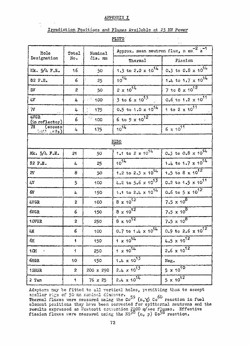
APPENDIX I
Irradiation Positions jand .Fluxes 'Ayailablg i at 23 IfiY Power
PLUTO '
HoleDesignation
Mk. 5/4 ?.B.
•S2 F.E.
5V
4V
TV4V&R(in reflector)7H (access
':';-!.•• •. r.5s)
TotalWo.
16
6
2
4
4
6
4
Nominaldia. mnj
50
25
50
- 100
. ;• 175' '';; 100
175
-2 -1Approx. mean, neutron flux, n cm. s
Thermal
1.3 to 2.0 x 101if
101/*
2 x 10^
3 to 6 x 10¹⁵ ..
0.5 to 1.0 x 101Z|-
6 to 9 x 10¹²
1014
Fission
0.3 to 0.8 x 101/f
1.4 to 1,7 x 10¹⁴
7 to 8 x 10¹²
0.6 to 1.2 x 10¹¹
1 to 2 x 10¹¹
•1 -16 x 1011
DIDO*
Mk. 5/4 Ï.B.
S2 F.E.
2V
4V
6V
4V&R
6VG-R
10VGR
4H
6H
1CH '
6HGR
12H&R
2 Tan
21
4
8
5
4
2
6
2
6
1
1
10
2
1
50
25
50
100
150
100
150
250
100
150
250
150
200 x 290
76 x 25
1.1 to 2 x 101^
101^
1,2 to 2.3 x 101i(-
4.2 to 5.6 x 10¹³
1.1 to 2.4 x 10¹⁴
8 x 10¹²
8 x 10¹²
8X10 1 2
0.7 to 1.4 x 10¹⁴
1 x 101/f
1 x 101^
1A x 101-3
2,4 x 10¹⁵
2,4 x 10¹⁴
0.3 to 0.8 x 10¹⁴
1.4 to 1.7 x 101/1"
1,5 to 8 x 10¹²
0.2 to 1.5 x 10¹¹
0.6 to 5 x 10¹²
7.5 x 10⁸
7.5 x 10
7.5 x 10⁸
0.9 to 2.6 x 10¹²
4.5 x 1C12
2.6 x 10¹²
Neg.
5 x 10¹⁰
5 x 10¹²
Adaptors nsv be fitted to all vertical holes, permitting thorn to acceptsrr.sller ri^s of 50 E-T. norurvcJ diar-v^xer. P- g0Thercal fluxes v.»ere measured using the Co"1"* (n," Co reaction in fuelelement positions they heve been corrected for epitherr.al neutron's and theresults expressed as '.Veatcott convention 2gOO C/KÇC fluxes. Effectivefission fluxes we re ceasured usJng the Ki- (n, p) Co^° reaction.
72

SUMMARY OF THE ENGINEERING PROGRAMMES PERFORMED INTHE BELGIAN RESEARCH REACTORS
byG. Stiennon
Commissariat à l'énergie nucléaire?00 Boeretang
Mol-Donk
Abs trac t
A survey of the engineering programmes conducted in the Belgianresearch reactors as presorted.
The Venus critical facility is used for experimental deterTi nationsrelated to the plutonium recycling •'r thermal reactors. The lov: flurBRI reacto^ is used for pctivation analysis and reactor i>hyslcs cali-brations. The high flux BE2 reactor is mainly used for fuel and struc-tural material tests for fast reactor and high temperature reactorprogrammes. The ER3 resctor, a small PY»R pov/er plant, is used for largescale testing of fuel elements for thermal water reactors.
The engineering programmes performed in the Belgian research reactors(Venus, BRI, BR2, DR3) are part of the Belgian five-year nuclearprogramme covering activities in the field of the fast and thermalreactor development. Such actions are jointly executed by the Belgianindustry (Rclgonucleaire, ACEC, MMN, ...) and the nuclear researchcenter at Mol (CEN'/SCK) .
Two important agreements, signed in 1968, fix the general frame of theprogramme :
The first is a Memorajidum of Understanding with the Karlsruhe and PettenNuclear Research Centers covering a joint programme of general resc-firchand development for fast breeder reactors; this action proceeded fromth<? basic agreement reached by the German, Dutch and BelgianGovernments on this subject. One of the major objectives of thisagreement is the joint construction in Germany of a fast breederprototype power plant.
73

The second acjr-eement concluded between the GfK (Gesel Ischaft furKernforschung) and CEN/SCK concerns the joint utilisation of theBR2 high flux reactor during the years 1969 to 1973 for the Germanas well as for the EURATOM and Belgian irradiation programmes.
In the present status report, only the Belgian programmes arementioned.
The VENUS zero-power reactor
The studies performed in Belgium, together by Belgonucléaire andSCK/CEN aim at providing a strong basis for the technical and economicevaluation of the plutonium recycle in the PtfR's and rely more particularlyon the experiments carried out in the VENUS critical facility.
A specific, study of plutonium recycle has been undertaken as an.exercise wit the SENA reactor characteristics taken- as a reference.The SENA Nuclear Power Plant (PWR, 266 MVe (net) ) located at Chooz,France, is operated jointly by "Electricité de France" and the BelgianUtilities.
Several plutonium recycle schemes, although not optimized, wereconsidered, based on the following arbitrary ground rules :
- the only -source of plutonium is that arising from the reprocessingof spent SENA fuel assemblies. This implies that the plutonium
thfrom the fuel unloaded at the end of the n cycle is reusedrdat the beginning of the (n -f 3) cycle
- the plutonium content in the successive reloads has to allow fora cycle duration of 8,900 EFP hours from the fifth cycle forward,i.e. the expected lifetime at equilibrium with uranium enrichedstandard reload fuel
74
- the plutonium in the reload fuel is either mixed with naturaluranium or with slightly enriched uranium arising from thereprocessing of the spent fuel assemblies
- the enriched uranium rods to be provided in addition to theplutonium rods have the same enrichment as in the case of noplutonium recycle
- the first plutonium loading takes plac? at the beginning of thefifth cycle
- all the reloaded assemblie.3 are identical to each other.
Calculations were first carried oat for the first core and thesuccessive enriched reloads from the first cycle up to the endof the fourth cycle considering reload 4 w/o U-235 enriched UO
A
stainless steel clad fuel» They were subsequently performed fromthe fifth cycle up to the beginning of the eight cycle consideringeither stainless steel or zircaloy cladding in the reload fuel; inthis reload fuel, the plutonium enriched rods were located in the centerof the assemblies and surroianded by U-235 enriched UO rods, according
£4
to a proper layout to minimize local power peaks» The requirement ofadequate form factors has been satisfied with one single enrichmentfor all the plutonium rods of a reload batch. Subsequent economicevaluations showed that for conditions prevailing around mid ?O?s,in the case of the SENA reactor, there could be a slight economicadvantage in mixing the available plutonium with slightly enricheduranium arising -from the reprocessing of the fuel assemblies ratherthan with natural of depleted uranium.
The VENUS experimental programme is defined with respect to the specificproblems involved in the calculations of the SENA core performances.
Spectrum averaged cross-sections for cell calculations and theoreticalformalisms are selected on the basis of the experiments, considering asufficiently high number of experimental conditions in order to avoidany arbitrary decision in the choice of the calculation methods»
75
Five types of oxide fuel, fabricated by industry, are mainly used inVENUS, with the following compositions :
4 % U-235
3 % U-235
2 % U-235
0.7 % U-2350.7 % U-235
no plutonium1.1 % PuO (7 % Pu~240 in the Pu)22.7 % PuO (17 % Pu-240 in the Pu)
5-1 °/o PuO (17 % Pu-240 in the Pu)&t
4.3 ?» PuO (low Pu-240 content - same fissile Pudensity as in the 0.7/5.1 fuel)
Transition regions at the boundary between two fuel zones of differentcompositions are investigated and also the environment of perturbationssuch as water gaps, absorbing rods, aluminium rods or plates. Plutoniumto uranium fission rate ratios in the fuel, power density distributions(including fine structure inside the rod) and the effect of fuelsubstitution or perturbations on the reactivity are the experimentalquantities which are compared with the corresponding theoretical values.Critical masses and po«r distributions are calculated with an agreementbetter than 0«5 and 5 ?i respectively with the measured values;calculated and measured fission rate ratios agree within the - 2 ?iexperimental error margin, in the spectrum equilibrium conditions.
The measurements with boric acid in the moderator (0 - 8OO ppm) arenow being started. Reactivity measurements in the subcriticai state(8OO - 2OOO ppm B) will be realised by the pulse method. Finally,specific problems arising from the utilization of rod cluster controland possibly of boron glass rods in modern large PWR's will be investigate
The BRI reacxor
BRI is a natural uranium - orapbits- rlevels are comprised between v.O kW ari-
2lmaximal thermal fluxes of 5 x HO ^nd
aftor , air r o o l e d . !he powe
a 1 M¥, with c.crr «-sp&r.ding"* *î "* '" K ?.o"~ n/cm'.s.
The samples irradiatc-a are ma^iy used !v/rfor various applications in t.r:f- i'i<::. -5s :»tbiology and agronomy «
76
v.**. i-'jn analyses, also~ps ,-hemi s'try , medicine,
Exceptionally, runs lasting A £>w hours ~?-e carried, out at the nominalpower of 4 MW to trace by noaxrcn antivatiors extraterrestrial dustpresent in South pole ice samples placed in a large cryostat.
Neutron flux Calibrations require-? for The reactor physics programmesconducted in other reactors &•"£ Carried o>;t regularly in variousfacilities of the BEI reaccoi-.
The horizontal thermal column nass bet-n provided with a 50 cm diameterspherical cavity containing a U-233 «phere provided with boron ÎOlayers and different thir Messes of polythene. In is facility is asubcriiicat one-dimensional fast assembly and is used for clean integralexperiments in different neutro.i spectra. These experiments supplementdifferential cross-section measurements in order to meet the severeaccuracy requirements imposed on «uclear data by economical considerations,Such facility, easily reproducible in other laboratories, is designed alsofor the international standardizaTion of the sandwich foil technique;proton recoils and Li (n d^. ) neutron spectrometers.
The BR2 reactor
The BR2 reactor uses enriched uranium, has a beryllium matrix and iswater cooled» T'he nominal power is 7O MW« The thermal flux ranges from
asl4 I1*! 210 up to 10 n/cm . s. The fast flux ( > 1OO keV> in the fuelelements ranges from 2 to 6 „ 10
The reactor is more and more intensively used for fast reactor fueltesting^ both oxide and carbide fuels are investigated mostly insodium cooling conditions» Carbide fuel studies are carried out atpresent in the frame of orientation research; as to the mixed oxidefuels, most work is concentrated upon the systematic irradiation of5 to 6 mm diameter UO -PuO needles, either irradiated in bundles2 &in sodium loops orlocaled in capsules introduced in great numbersimultaneously in the reactort each capsule containing one singlefuel needle.
77
In order to reproduce, as correctly as possible with a thermal reactor,the irradiation conditions of a fast reactor, two types of irradiationdevices have been considered,, The assembly to be irradiated eithercan be surrounded by a thermal-to~t .st conversion zone, consisting ofsodium or gas cooled enriched fuel pins» or can be inserted in one ormore tubular thermal neutron absorbing screens, made e.g. of cadmium.Although from a neutron point of view the letter type of irradiationdevice obviously has less good characteristics than the former one,all irradiations were performed up to now in the latter type as itcan be realized in a much safer and cheaper way* By increasing theenrichment of the needles in U-235; the main specifications can never-theless be fulfilled with these devices, the effect of fast neutronson structural materials exceptedc Indeed, one year (or 25O EPPO) exposurein such facilities in the present conditions corresponds approximatelyto a 70,OOO MWd/t burn-up level at A specific linear power of 5OO W/cmand with a radial fission density distribution in the fuel engenderinga temperature distribution sufficiently near to that characteristicof fast reactors» The neutron J'luenos above 0»! MeV is neverthelesslimited to 1 - l.J lO* ' n/onT „
The main object of all studies performed in connection with the reactoroperation is the way of increasing the (annual) reactor fluency. Severalmodifications of the BR2 reactor are being considered or are alreadypartly realized at présente
1Tn to now, the flux level in BR2 was mainly limited by the capacityof the cooling system which amounts to about 75 MW. Because of theimportance of the core loading imposed by the necessity of compensatingthe negative reactivity effect (4 to 5 % at present) of the experimentaldevices and by the aim of obtaining a cycle operation time - i.e.a utilization factor (0.6 at present) - as high as possible, the averagecore power density is limited to about 2 MW per fuel element. Thiscorresponds approximately to a maximum value of 850 kW/1, calculatedover the cell. The installation of new heat exchangers at the beginningof 1971 will allow the capacity of the cooling system to be increased up
78
to 1OO MW. Further extension up to 175 MW is envisaged; the maximum fuel2 2element heat flux would then reach 60O W/cm (instead of 40O V/cm
at present). The thermal tests performed in Î964 have demonstratedthat such performances can be achieved without modifying the water flowrate in the fuel channels.
The possibility of increasing the number of fuel tubes per element,going from 6 to 7,8 or even 9 tubes, is also considered» Thismodification would result in a substantial increase of the powerdensity and in a hardening of the flux spectrum<>
Another improvement consists in the use of fuel elements with burnablepoisons. From 1970, one third of the core loading wiH be made of uraniumaluminide (UA1 ) containing boron and samarium; the utilization ofthese elements will progressively be generalized. The principaladvantage will be the increase of the cycle operation time from15 to 25 days« Further interesting features are :
- the number of control rods can be reduced, as they will have tocontrol a decreased reactivity variation; the spatial distorsionand the time dependence of the fast flux will therefore besmaller; for this reason, and also because the fuel loading willbe more compact, the average core power density will be increased,for a same maximum heat flux
- the flux spectrum hardens slightly,
The annex gives a view of the different types of irradiation devicesused ât BR2.
Qne of the goals in the development of irradiation facilities for fastreactors is to be able to irradiate fuel and materials in improvedconditions :
- in loops, by increasing progressively the size of the test finger(9 - 19 fuel pins), the thermal capacity (2OO - 5OO kW) and thenumber of in-pile sections
79
- in capsules or rigs, by increasing the power density and improvingthe measuring devices or sensors.
This technological effort has to be supported by detailed neutronicassessments, theoretical computations and experiments on mock-ups inthe BR02 reactor (nuclear model of the BR2 reactor).
The irradiation programme for the fast reactors may be summarizedas follows :
Mixed oxide fuelsIn the frame of an association with Belgonucléaire an extendedprogramme is carried out on uranium-plutonium oxide fuel. A partof this activity is devoted to the development of the fuel ,for the300 Mtfe prototype fast reactor SNR»
Carbide fuelsThe objective of the project is to develop UC, (UPu)C and (UPu)C,Nfuel presenting the required compatibility with the canning materialand an acceptable swelling rate under irradiation. The conductedirradiations will enable to clarify the behaviour of the stabilizedfuel (Va-Cr).
Canning materialsTechniques for producing a dispersion hardened ferritic steel arestudied, the dispersed phase is TiO and the metal matrix is2Fel3 Cr2 Mol ,W, improved by the addition of titanium. Long termirradiations are under way.
In the field of thermal reactors, fuels containing plutonium areirradiated under extreme conditions. Different fabrication techniques(palletizing or vibrocompacting heterogenous powders) are tested.U0_ pencils containing burnable poisons (Dy O ) are also irradiated.2 ct j
In the field of high temperature gas reactors, coated fuel particlesare extensively experimented.
80
Besides structural and fissile materials irradiation, the BR2 reactor isalso used for isotope production (Co, Ir, Ac, Cm, ...) and beanexperiments (neutron physics, safeguards, ...).
The BR3.reactor
BR3 is a PVR reactor, with a thermal power of 40,9 MW (11,5 MWe).After a successful operation as spectral-shift reactor (Vulcain)where the peak pellet burn-up reached about 50T000 MWd/tU, thereactor BR3 returned to PWR operation!
The present core (2 bis) has been constituted in the first part of1969 with 39 fuel assemblies chosen among the 73 irradiated fuelassemblies of the BR3/Vulcain core and 3^ newly fabricated fuelassemblies, the general disposition of the core and the reactorvessel internals remaining as during the BR3/Vulcain experiment.The 2bis co're is nevertheless moderated and cooled with ordinarywater, the reactivity investment being in a large amount controlledby boronation of the moderator.The purpose of this experiment is twofold :
- to gain fir at experimental data on advanced fuel assembliesand especially on the design and the fabrication process ofZr clad fuel pins
- to carry on with the test of the Vulcain stainless steel cladfuel.
Indeed, between the 3^ new fuel assemblies, 16 are loaded with Zircaloyclad fuel pins maintained by Inconel grids, 8 of these assemblies werefabricated according to a new 'design eliminating the shroud; on theother hand, the maximum burn-up level'(peak pellet) in the 39 fuelassemblies reshuffled from the Vulcain core is expected to lie
» ' ! j
between 40,000 and 50,OOO MWd/tU at the end of life of the 2biscore,with the exception of the central assembly that was left in itsori.ginal position and should reach a peak burn-up of about 57,OOOMtfd/tU.
81
Being .made first critical on July 9, 19^9, this core has beenoperated at power since July 31- The power level was increasedgradually to prevent early damage of the reshuffled fuel assembliesand, up to now, was most of the time maintained between 6.5 and8 MWe. At the end of June 197O> this core has been operated duringapproximately 7i500 hours, the integrated mean thermal power reachingabout 8,400 MWd/t (LN-Pu).
The reactivity investment appears, as theoretically foreseen, to besuch that a mean thermal energy of approximately 10,000 MWd/t (U-i-Pu)could be produced, corresponding to 250 EFPD. It is now debated howfar the power level of the core will be further raised, consideringthe benefit of increasing the sollicitations of the fuel and tho careof keeping the primary water level activity at acceptable level tolimit operation problems.
The Belgian industry is designing, on behalf of SCK/CEN, the nextcore (core 3) due to be operated during approximately two and a halfyears, from October 1971 on.
The main objectives of the operation of this core are :
- to gain experience on the behaviour of a Zircaloy-clad core athigh burn-up level, under irradiation conditions representativeof those which will be encountered in the future Belgiannuclear power plants
- to scale up the experience on mixed U-Pu oxide fuel obtainedduring operation of the previous BR3 cores by the introduction ofapproximately 500 fuel pins of this type; the pins will befabricated by various techniques which will be compared
- to test various other core components.
82

The delay for obtaining results from the core 3 experiment beinga major concern, it has been decided to maintain the general layoutof the core as for the core 2 bis, taking advantage of the existingvessel internals; therefore, the core 3 will be made of 73 fuelassemblies with hexagonal cross-section whereas assemblies withsquare cross-section will be used for the core 4 as in conventionalpressurized water reactor.
The core 3, moderated and cooled by boronated light water, willnevertheless consist of two types of fuel assemblies having onlyin common the hexagonal prismatic form and overall externaldimensions; the first type contains 3& °r 37 Zr clad fuel pins(8.7 mm O.D.) in a triangular lattice : part of the fuel assembliesof this type will be reshuffled from the core 2 bis; the secondtype contains 2O Zr clad fuel pins of larger external diameter(10,7 mm) arranged in a regular square lattice, pins and spacing gridsbeing fabricated according to the design adopted for the future largepower plants : the grids will be fixed to an external hexagonal shroud.
The general target is to produce with the core 3 an integratedthermal poxver of 25,OOO MWd after two irradiation campaigns with anintermediate reloading (hence core 3A and core 3B); the fuel weightin each core is close to one ton. In core 3A, half of the fuelassemblies will be of the square lattice type; this fraction willbe increased to three quarters in core 3B, most of the fuel assembliesreshuffled from the core 2bis being unloaded after the core 3Airradiation campaign (one and a half year).
During all the core 3 experiment, a total of approximately twentyfuel assemblies of both triangular and square lattice types willcontain mixed (U, Pu) oxide fuel pins.
Some poison (pyrex glass) rods will be distributed within the fuelassemblies; it is also worth mentioning that internally pressurisedfuel pins will be tested.
83

A preliminary study of core 4 is mainly devoted to the analysis of theways of increasing the flexibility of the plant operation, allowingprimarily an easier access to the core components; such a fourth corewould make the BR3 power station an oven more interesting tool fortesting poivrer plant core components and operational procedures with ahighly contaminated primary circuit.
84
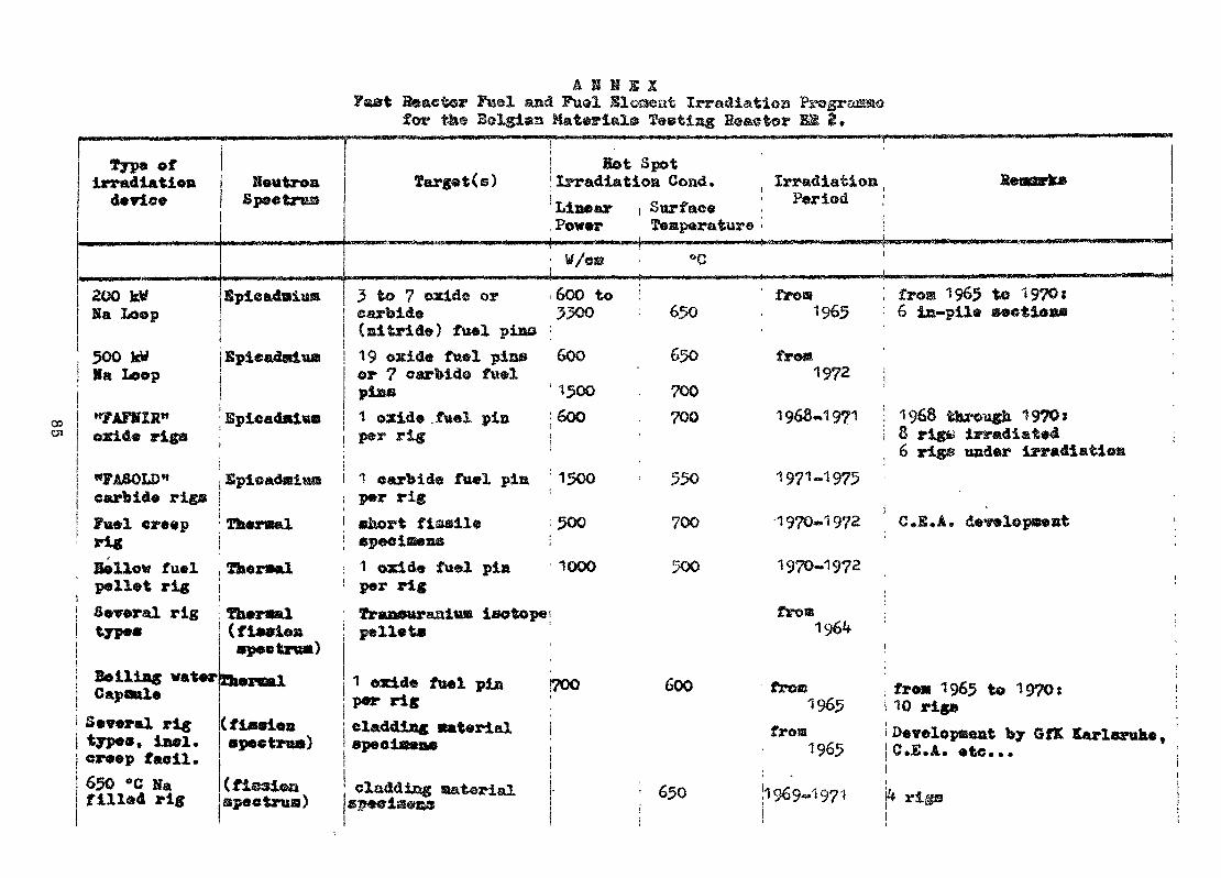
Fsst B&aetor Fml and Fual Sloaeat Irradiation Program®for th® Bslgiaa Materials îeetla Eesstor
Oi
Type ofirradiation i Heutroa
jf „-{ *k—. C «Mffc J» <fr-<MPK« <Sft
1i
200 kWSa Loop
Spi«sadsiK®
?arget(@)
5 to 7 oacide orcarbide(aitride) fuel pins
500 ktf JBpieadsiu» i 19 oxide fuel pirn»Ha Loop
«yAFKIR"oxide rigs
«FASOLD"carbide rigsFuel creeprigBellow fuelpellet rig
or 7 carbide fuelpiss
SpicadnittB ! 1 oxide .fuel pisper rig
Spieadffiiu® 1 oarbid© fuel pinper rig
Thermal eàort fissileepeeiseas
Theraal 1 oxid« fuel piaper rig
Several rig ! fberval ; Traasuraalusj isotopetype»
Boiliag waterCapQttleSeveral rigtype», iaei.creep faeil.65O °C Hafilled rig
(fi*siea pelleté•peetrua)Zbercal 1 oxide fuel pia
per rig(ficoiea cladding Btaterialspectra») epeoloeas
speotraa) claddi&g aatorial
t . ..Eot Spot
Irradiation Cond,Linear
, Power; W/CS
600 to5500
600'1500600
1500
500
1000
I700
i SurfaceTeffiparature
• °C
650650TOOTOO•
' 550
TOO
500
600
: 650
- - -, 0.
Irradiation Sean -JsB; Period•
fro»1965
from1972
1968-1971
fro® 1965 to 1970t6 ie-pila &e$tioa@
1968 t&roug& 19?0ï8 rige irradiated6 rigs under irradîatiom
1971-1975
1970*1972 O.S. A. dewlopsest
1970-1972
fros196
from fro» 1965 to 1970:1965 10 rig»
from i Development by GfK Earleruhe,1965 IC.E.A. etc...|1969-1971 f* rigs
Questions and/or Comments
What are the approximate operation costs for the BE 2 reactor ?The operation cost of the whole set-up of the reactor, including thesupporting technology, i.e. including from the beginning of theexperiment design until the sample comes out to be sent for scientificexamination, is about 7 million ÏÏS dollar/year. This includes thesalaries of about 350 persons working in the facility.
What are the limits in a thermal reactor with high flux con-cerning experiments from a, fast reactor ? The limits of the irradiationsin a thermal reactor for a fast reactor programme are clearly difficultto define, it depends, of course, on the conditions and on the final aim.For example, a limit which cannot be exceeded is to maintain thecorrespondence between the burn-up of the uranium and the damage in thecladding. There is always the effect of 3 or 4 in the damage to thefuel elements as compared to a situation in a real fast reactor. In afast reactor the flux depression, due to a fuel pin, is rather small,especially when it is compared to that occurring in a thermal reactor.These are some of the limitations encountered.
Other experiments connected with fast reactor safety which can beconducted ir. thermal facilities are namely transient studies of fuelfailure and defective fuel behaviour in sodium loops.
86
INSTALACIOH DE UN REACTOR DE INVESTIGACIONEN UN PAIS EN DESARROLLO
J. Spitalnik
CENï<RQ BE INVESTIGACIJNBS NUCLBÂRSS, MONTEVIDEO,UHUGUAY
Absjijract:The creation of a nuclear research centre In Uruguay,that would unify the dispersed efforts,being carriedout in several fields of nuclear energy applicationshad to face two alternatives: either to buy a 1 MWresearch reactor package from a foreign manufactureror to try to install it through local engineering,labor and finance.It was considered that the second alternative was themost convenient for introducing new technology to anddeveloping the industrial potential of the country.The experience gathered by making this effort could pointto some of the difficulties an engineer of a developingcountry might encounter in a similar situation.
ResumenLa creacion de un Centro de ïnvestigaciones Nuclearesen el Uruguay, que unifique los esfuerzos disperses lle-vados a cabo en los diferentes campos de las aplicacionesnucleares, tuvo dos alternativas: comprar un reactor deinvestigation de 1 MW a un fabricante extranjero, o tra-tar de instalarlo con ingenieros, mano de pbra y finan-ciacion local.Se considerÔ que la segunda alternativa era la mas con-veniente para introducir ,al paîs la tecnologîa modernay para desarrollar el potencial industrial existente.La experiencia adquirida en la realizaciôn de este es-fuerzo puede apuntar hacia algunas de las dificultadesque un ingeniero de un paîs en desarrollo tendrîa queencarar en una situacion similar.
87
1. IntroducciSn.Hay casi 70 paises en desarrollo que son Estados Miembros delOrganisme Internacional de Energîa Atomica y solaraente cerca de25^*' tienen o estân instalando un reactor de investigacion. Estosignifica que todavîa existe, entre los paises en desarrollo, ungran potencial para la construcciôn de reactores de investigacion,y no hay duda que se requerirâ mue ho ingenio y esfuerzo de adapta-ciôn para introducir y desarrollar en ellos la tecnologïa nuclear.La experiencia obtenida en la realisacion de un esfuerzo total-men te nacional para proyectar e instalar el reactor de investiga-cion de Montevideo podrïa apuntar hacia algunas de las dificulta-des que, en situaciones similares, tendrïan que encararse.El hecho de que dicho esfuerzo esta sîendo llevado a cabo en unpaîs en desarrollo—en el que el nivel de experiencia y refinamien-to industrial es todavîa primitive—podrïa hacer pensar en una fal-ta de conocimiento sobre la coraplejidad de los problemas involucra-dos. Sin embargo, este ejercicio se ha basado en un buen nivel decapacitaciôn en ingenierîa y en una mano de obra bien experimentadalo que ha permitido ponerlo en marcha con cierta confianza. Loshechos estân demostrando que la décision de llevar a cabo esteproyecto ha sido acertada.2. Objetivos.El principal objetivo del proyecto ha sido la creacion de un centrede investigacion en el cual se concentrarân las actividades nuclea-res del paîs, para unificar los esfueraos disperses que existen enlos diverses campos de la aplicacion de la energîa atômica. Talesquema implica evitar la duplicaciôn innec^saria de personal yequipo asî como permitir la instalaciôn econoraica de aparatos demayor capacidad. El resultado conducirâ a un uso mucho mSs eficazde la pequena coraunidad de cientîficos del paîs y constituirâ unmedio mas economîco para el desarrollo de dichas aplicaciones.Âdemâs, como esta empress tenîa que ser encarada sobre todo con per-sonal y recursos financières locales, se ha logrado formar un grupode ingenieros y cientîficos con cierta experiencia en el diseno yla construcciôn de instalaciones nucleares. EP de esperar que, conla confianza adquîrida, podrân resolver îngeniosantente los problemasinvolucrados modiante el mâximo uso de los recursos locales.Este grupo podra transformarse en el equipo bâsico nacional paraintroducir en el paîn tecnologîas modernas, especialmente la nu-clear, y para entrenar a la industria a atenerse a los nuevosrequisites de dichas tecnologîas, lo que conducirâ a un mayor re-finamiento de la inganicrîa local. La araplia preparacion de estoscientîficos e ingenieros, gracias a un contacte directe con losproblemas relatives a la energîa nuclear, permitirâ tambiên equi-parse con un grupo nacionel bien calificado para considerar y es-tudiar, cuando sea necesario, las propuestas y ofertas de centra-les nucleoelectricas. Y esto es una ventaja que no deberîa de sersubestimada, ya que cualquier nacion necesita tener la seguridadde un asesoraniento digno de confianza, por parte de expertes na-cionales, para realizar invcrsiones importantes y esenciales.
88
3. Condiçionantes.Tal como se ha indicado anteriormente, el proyecto tuvo que comen-zarse con las siguientes limitaciones:
--escasez de ingenieros y cientîficos especializados en cienciasnucleares-preaupuesto limitado-falta de desarrollo y tradicion industrial
En el haber las condicionantes eran:-buen nivel educacional en las ramas bâsicas de la ingenierïa-existencia de personal obrero y tecnico altamente capacitado-buenas relaciones entre la Universidad de la Republica y laComision Nacional de Energîa Atomica (CNEA)-existencia de un reactor de investigation de 10 KW desarmadoque habïa sido usado previamente en una expoaieion de losEstados Unidos.
Las limitaciones iniciales fueron abordadas mediante la seleccionde un grupo de ingenieros mecanicos, electrotëcnicos y quïraicosasî como ingenieros civiles y arquitectos, para trabajar en el pro-yecto» bajo la direccion de un ingeniero nuclear con experienciaen ingenierïa mecânica. Los ingenieros quïmicos tenïan una buenabase en radioquimica.Se procedio a la siguiente division de târeas entre los miembros delgrupo: fîsica del reactor, blindaje y seguridad del reactor, inge-nierïa civil del reactor, refrigeracion del reactor, disposicion ftr-quitectonica del Centre, ventilaciôn y acondicionamiento térmico delCentro, eliminacion de residues radioactives, -laboratories de radio-quimica, ingenierïa civil, sanitaria y eléctrica del Centro.Jista tarea fue llevada a cabo por la Universidad de la Republicausando al maximo a sus propios profesionales . Tambiên se/firm5un convenio, entre la Universidad y la CNEA, mediante el cual laUniversidad debîa realizar el proyecto del Centro y supervisar suconstruccion, dando ënfasis a la instalacion del reactor. Laresponsabilidad de la construccion del Centro recayS en el Minis-terio de Obras Publicas.El proyecto debîa hacer uso de un reactor portatil del tipo pis-cina de 10 KW de potencia, que habïa sido exhibido anos atrâs enMontevideo. Uespuës de la exhibiciôn fue coœpletamente desarmadoy adquirido por el gobierno de Uruguay. Los elementos combusti-bles fueron donados por los Estados Unidos a travës del OIEA.Aun cuando se curaplîo con el requisite de usar este équipe, seobserve que, si al ûnico reactor que iba a tener el paîs no se leaumentaba la potencia, iba a ser posible usarlo solo para entre-namiento y no para investigaci6n y produccion. Per lo que, ini-cialmente, se procedio a realiaar un proyecto de un reactor deltipo piscitia;de 100 KW de capacidad. Posteriormente, la misma seincréments a 1 MW, nivel actual de potencia.
89
4. Caractèrestieas principales.À pesar de haber utilizado los elementos combustibles y otros dis-positivos — principalmente équipes de control y de tnedida de radia-ciones—-que pertenecîan al reactor original de 10 Of, el nuevo di-seno se aparta fundament a Intente de aquél, y puede ser consideradocomo un concepto completamente novedoso realizado por el personallocal (fig. 1).Este reactor tendra las siguientes dimensiones: 3,2 m x 2,5 m y7,6 m de profundidad.La piscina se recubrira de acero inoxidable. El blindaje, alrede-dor de très lados del nucleo, consistera en hormigon pesado de1,4 m de espesor, intercalado entre dos parades de hormigon arma docomun de 0,3 m de espesor cada una (fig. 2).Ambas parades servirân de encofrado para el hormigon pesado ya que,por ser un material desconocido para los obreros, este sistematendra la ventaja de no tener que entrenarlos en el uso de enco-frados especiales para el hormigon pesado. Adenas, el hormigonpesado no tendra que trabajar bajo carga, lo: que permitira dismi-nuir la proporciôn, de hierro y, por lo tanto, se evitarâ el peligrode aparicion de grandes fisuras. La densidad del hormigon pesadosera de 3,5 g/cm-* de acuerdo a las relaciones entre aridos, agua ycemento determinadas por el Laboratorio de ensayo de materiales.dela Universidad, sobre muestras de minéral de ilmenita existente enel paîs. El resto del blindaje consiste en hormigon comun y suespesor, decrece hacia arriba (fig. 3).El tanque de acero inoxidable que recubre la piscina sera un elementoque por. primera vez se construira en el paîs. Sin embargo, la in-dustria esta en condiciones de comenzar inmediatamente su armadopues to que los soldadores locales tienen una buena practica en estaclase de trabajo. El tanque servira de encofrado interne para lapared interior de hormigon comun del blindaje. Tendra, entonces,que colocarse en posicion antes de comenzar el vaciado del hormigon.Para evitar esfuerzos importantes sobre las paredes del tanque, seira llenando con agua métro a métro, a medida que se levanta la pa-red de hormijon.Se instalarân cuatro tubos para haces neutronicos de 15 cm de diâ-metro. En caso necesario, estes tubos podrân retirarse, para per-mitir que exista espacio libre alrededor del nucleo. Se les fijarâ auna platina colocada en el medio del blindaje (fig. 2).Tambiën se ha previsto una columna tërmica cuya instalacion no secompletara inicialmente, por lo que, el espacio reservado para elgrafito, se rellenarâ con bloques de hormigon pesado. La inversionpara la adquisîcion del grafito y el recubrimiento interno de boralno se harâ hasta tanto los cientîficos que necesiten la columnatërmica estên préparâmes para usarla.El sistema de enfriamiento tampoco se instalarâ al comienzo delfuncionamiento del reactor. La inversion correspondiente se demo-rarâ durante el perîodo en que se realicen calibraciones inicialesy las determinaciones de los flujos neutronicos. El reactor operarâ
90
inicialtnente a 10 KW con circulacion natural, y mas adelante, seins t ai ara el sistema de enf riaraiento . !il diseno permite una facilintroduccion del colector y las canerïas correspondientes (fig. 3).El reactor podrâ operar entonces a 100 KW hasta que se conecte, ala canerîa que esta dentro de la piscina, un tanque de decaimientode N*** y se agraguen nuevas bombas e intercambiadores de calor parael f uncionaraiento a 1 MW .El .reactor estara ubicado en un edificio de 18 m x 18 TO y 15 m deaituray por l<> que exâstirâ ampli i espacio libre para ef ectuar^expe-riencias alrededor del reactor. En la parte superior, existira una.plataforma de trabajo conectada por un puente a la sala de comando.Este edificio estarâ en depresion atmos f êrica » por razones de seguri-dad, aunque no se requière que sea h.ermêtico. Habrâ cuatro renova-ciones de aire por hora y se controlarâ su actividad, antes de^en-viarlo a la chimenea. Solamente en energencias, se incorporarânfiltres absolûtes al circuito de ventilacion. En condiciones norma-les de trabajo, el aire sera derivado, sin pasar por los filtres,para evitar una colmataeion innecesaria.A pesar del resultado exitoso con que se ha ejecutado este proyecto,no debe existir duda alguna sobre la necesidad de asesoramiento porparte de paises mas adelantados . Generalmente , despues de tomarseuna décision, la crîtica de gente mas experimentada résulta positiva.tLsto fue realizado, en este caso, raediante discusiones frecuentescon ingenieros y cientïf ico.s, de la Comision de Energîa Atomica deArgentina. Gracias a su generosa disposicion, fue posible confir-ntar la correccion de las soluciones ticnicas propuestas o efectuarpequenos cambios para mejorar el dis-eno. Kn menor grado, se.con-sulto también a los ingenieros del fàbrieante del reactor originaly a expertes de Francia y Espana. El grupo pudo asî establecer undialogo con gente mas experiraentada y, adquirir entonces, una segu-ridad en su propio juicio, lo que fue fundamental para el ëxito delproyecto.5 . Aspectos economicos iîl costo del reactor de 1 MW, sus auxiliares y el edificio, incluyen-do los costos del prcyecto, del reactor original de 10 KW y de su com-bustible, «alf.anzarâ solamente a ~a mitad o un tercio de lo due bancostado en . otros paisej; itistalacîones nuclearesLas razones de un presupuesto relativaraente tan bajo han sido la com-pléta utilizacion de los recursos locales para los principales rubrosrelacionados coti la ingenierïa civil, que représenta un porcentajemuy âltd.-del costo; los elementos del dâ.seno del reactor^ que permi-tieron evitar requisites constructivos especiales, y el uso de manode obra y materiales nacionales.Se contemplarâ solamente la iraportacion de materiales (taies comoboral, • ;;raf ito , eleraentos. combustibles adicionales) o équipes (medi-das de râdiàciones , ?ins trùmentos electrônicos , filtres absolûtes,equipos de laboratories: calientes , ^rûa puente, bombas e intercam-biadores de calor de ac,ero inoxidable) que no puedan obtenerse enplaza. Ln la medida de lo posible, se tratara que lc?,s rubros impor"*tados provengan de los paises vecinos que puedan suminis trarlos , paraconseguir fâcilmente repuestos y servicio de reparaciôn, asi comopara contribuir al desarrollo industrial regional.
91

Tarabiên, para obtener la maxima eficacia de la asistencia extranjeraal proyecto, se han coordinado los prograraas de asistencia tëcnica^de diverses organismes internacionales y los acuerdos de cooperacioncon otros paises en el campe de la energîa nuclear. ûe este modo hasido posible ahorrar una cantidad sustancial de divisas para la pro-vision de equipo importado para el Centro. Al mismo tiempo se estallevando a cabo un plan de especializacion, en el extranjero, decientîficos mediante becas. Estos cientîficos han seleccionado cam-pos de estudio en los que hay un déficit local y, a medida que fina-licen su especializacion, se incorporarân al grupo que operara alCentro.6. Cônelusiones.La integracion del grupo de ingenieros del proyecto y el^diseno delCentro han llevado solaraente nueve meaes. La construccion ya se hainiciado: la fundacion del reactor esta terminada y el edificio de loslaboratories esta en construccion (fig. 4). Se espéra que, dentro deun ano se producira la criticidad del reactor.La decision de embarcar el esfuerzon nacional en el disefio y lainstalacion del Centro de Investigaciones Nucleares ha engendradodiversas ventajas.
-Ha ayudado a desarrollar el potencial ticnico local perraitiendo,asî, obtener un conocimiento directe de la ingenierïa de los re-actores nucleares. Lo mismo puede decirse de la mano de obra eindustria existentes, que pudieron aplicar de este modo, su peri-cia y câpacidad a las necesidades y especificaciones de la tec-nologia moderna.-Las soluciones tëcnicas, encontradas mediante la combinaciônde los requisites de la tecnologîa actual con las limitacioneslocales, han conducido a. los conceptos que mas economicamentesatisfacen a dichos requisites y a las condiciones del paîs.-lia permitido adquirir un conocimiento exhaustive de los deta-lles de la instalacion, aûn los menores, cosa que no es tanfacilmente obtenible cuando se importa completamente la insta-lacion. Iambien, de este mods, el trabajo de manutenciôn yreparacion se puede llevar a cabo en forma mas eficaz y, ade-iaas, mediante èl use de materiales de plaza.-La craacioii de un grupo de ingenieros, con seguridad de poderencarar problecias de reactores nucleares, auoenta la posibilidadde poseer un grupo nacional que pueda asesorar con autoridad enproblèmes nucleares de mayor iraportancia, como lo es la adqui-sicion de centrales nucleares de potencia.-El establecimiento de relaciones mas estrechas con expertes depaises vecinos, que han experimentado las mismas dificultadesen el logro de objetivos semejantes, puede ser fructifère cuan-do, luego de desarrollar al C.I.N., se encare la ejecuciôn deprograraas de trabajo comunes sobre una base régional.
92
-lîl uso planificado de la asistencia tecnica internacional obilatéral, de un modo pfogramado, conduce a una utilizacioneficaz de los limitados recursos que existen para las aplica-ciones nucleares.-Ha dado la oportunidad para que afloren los recursos latentesdel paîs y asïs contribuir al desarrollo nacional, lo que de-biera tener siempre prioridad antes de solîcitar ayuda extran-jera. Al respecte, es interesante citar lo expresado por unpaîs daserrollado a la consulta sobre cuâles son las condicio-nes financieras especiales que se considerarïan para las cen-trales nucleares que pudieran suministrar sus fabricantes alos paises en desarr jllo ' : "..«la verdadera solucion del pro-blema del financiamiento de la energîa nucleoelëctrica radicasobre todo, en la buena concepciôn tecnica y economica del pro-yecto en cuestion, asî corao en la prioridad que se asigne al es-tablecimiento de una infraestructura cientîfica y tecnolôgica."
Titulos de las figuras
fig. 1. Perspectiva del reactor de investigacionuruguayo de 1 MW.
fig. 2« Planta del reactor.fig. 3. Corte vertical del reactor.fig. 4. Estado de la construccion del Centro de
Investigaciones Nucleares (junio de 1970),
93
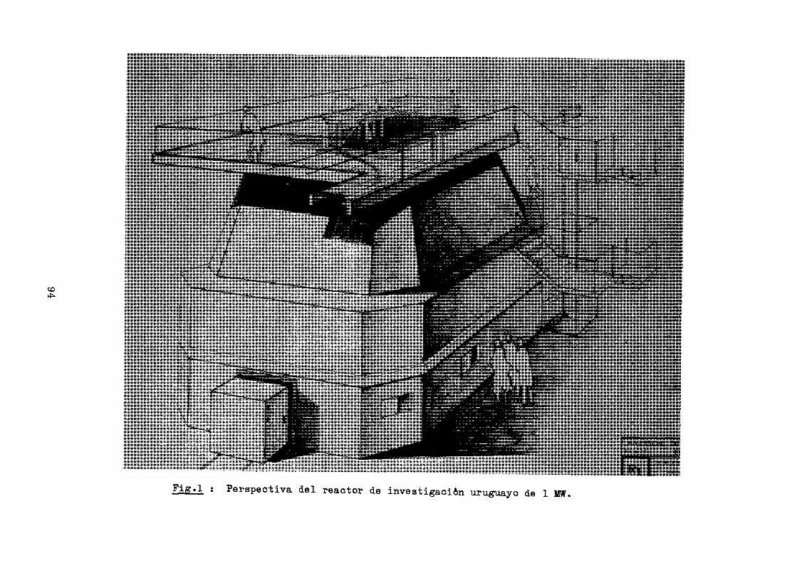
CD
Fig*j-, : Perspectiva del reactor de investigacién uruguayo de l
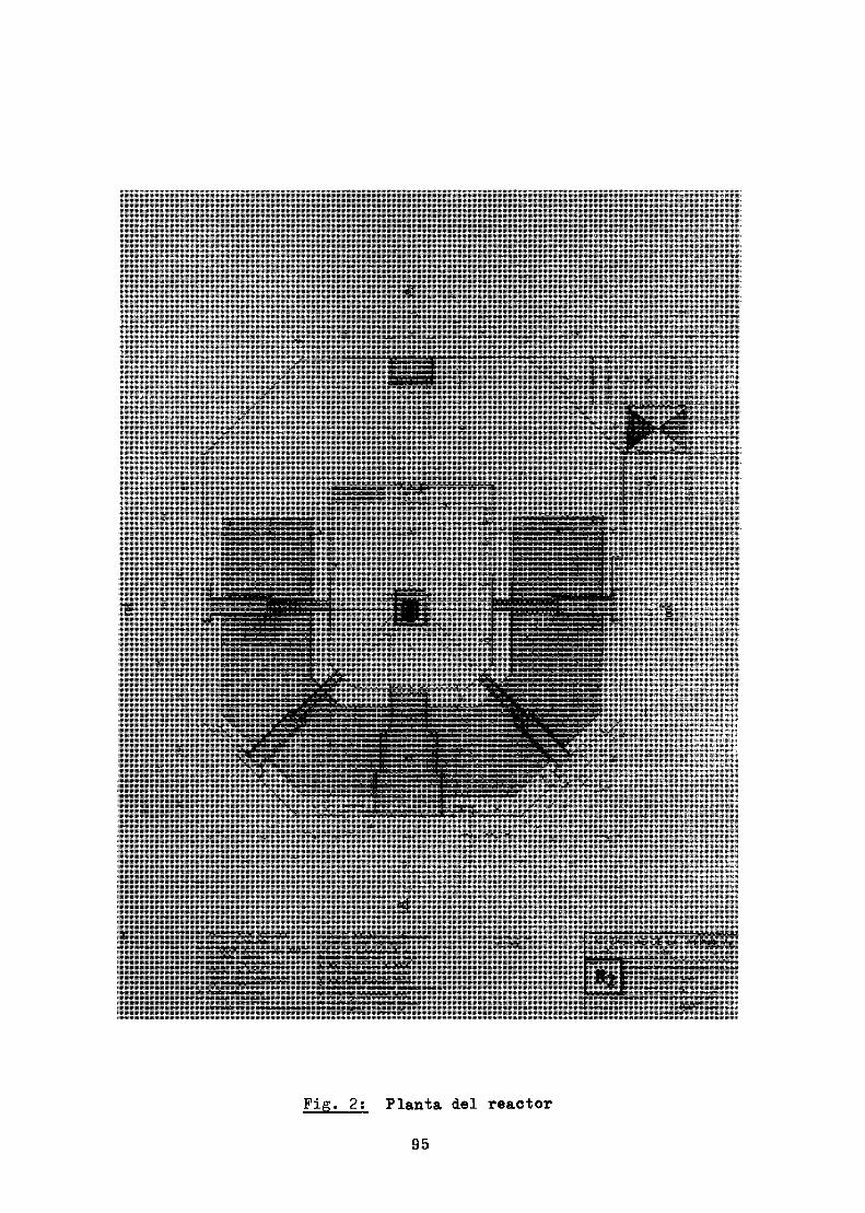
Fig. 2; Planta del reactor
95
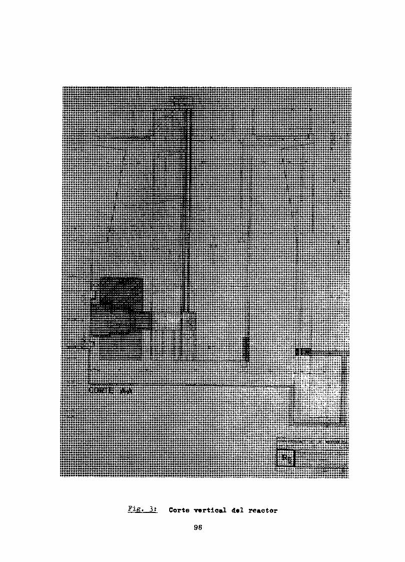
3t Corte vertical del reactor96
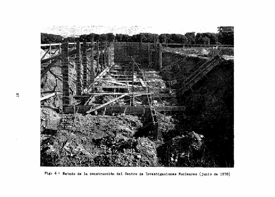
4 • Estado de la construcciôn del Centre de Investigaciones Nucleares (junio de 1970)
Referencias
fl) Power and research reactors in Member States -Edicion Set. 1969, O I E A , S T I / P U B / 1 9 4 .
(2) Directory of Nuclear Reactors - Vol . VI - Research,Test and Experimental Reactors. OIEÀ, 1966,STI/PUB/125.
(3) Financiamiento de proyectos nucleares - OIEA - Juntade Gobernadores - Informe provisional del DirectorGeneral - GOV/1403.
Questions and/or Comments
In the reactor cross-section no tangential beam tube is shownand tangential beam tubes have the advantage of better neutron togamma ratio, the neutron physics people will very much benefit fromsuch facilities.
We have thought about the tangential beam tube and it was in-corporated in our ir.itiai design, however, we wanted to have a veryeasy access to the core and therefore we thought that the beam tubeswould litr.it the free access. So we installed removable radial tubeswhich, at a certain stage, can be taken out, therefore having freespace all around the core. The design of the tangential removabletube was accomplished although jt was very dif f icul t , but we decidedto use tangential instead of vertical tubes.
How many professional people are involved in the constructionand design of the research reactor ? Not more than 30.
What form of benefit do you get by employing local industry ?We are giving local industry the first insight of the problemsrelated to modern technology requirements. This is the first timeour people in the industry will have to look very closely totolerances, welding quality, and special aandling of larger partsthan they are used and equipped for.
98
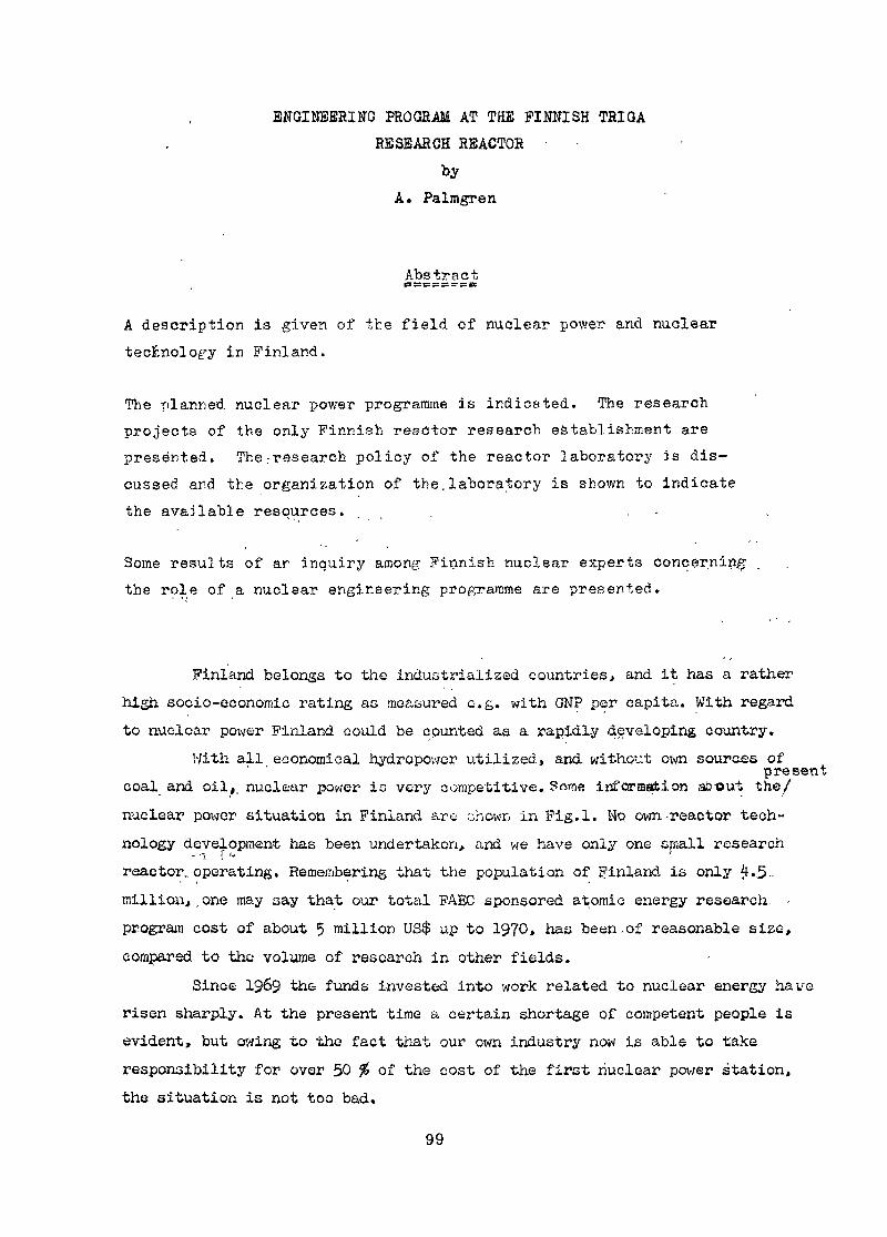
ENGINEERING PROGRAM AT THE FINNISH TRIGARESEARCH REACTOR •
byA. Palmgren
Abstractgs 5= c = si sr K at
A description is given of the field of nuclear power and nucleartecfcnolog-y in Finland.
The planned nuclear power programme is indicated. The researchprojects of the only Finnish reactor research establishment arepresented. The .-research policy of the reactor laboratory Js dis-cussed and the organisation of the.laboratory is shown to indicatethe available resources. . .
Some results of ar inquiry among Finnish nuclear experts concerningthe role of a nuclear engineering programme are presented.
Finland belongs to the industrialized countries, and it has a rather-high socio-economic rating as measured e.g. with GNP per capita. With regardto nuclear power Finland could be counted as a rapidly developing country.
With all economical hydropower utilized, and without own sources of' ' presentcoal_ and. oil,, nuclear power is very competitive. S runs information about the/nuclear power situation in Finland are chown in Fig.l. NQ own-reactor tech-nology development has been undertaken, and we have only one small research- •-< i •'reactor, operating. Remembering that the population of Finland is only 4.,5-.million,,one may say that our total FAEC sponsored atomic energy research. -program cost of about 5 million US$ up to 1970, has been-of reasonable size,compared to the volume of research in other fields.
Since 1969 the funds invested into work related to nuclear energy haverisen sharply. At the present time a certain shortage of competent people isevident, but owing to the fact that our own industry now is able to takeresponsibility for over 50 % of the cost of the first nuclear power station,the situation is not too bad,
99
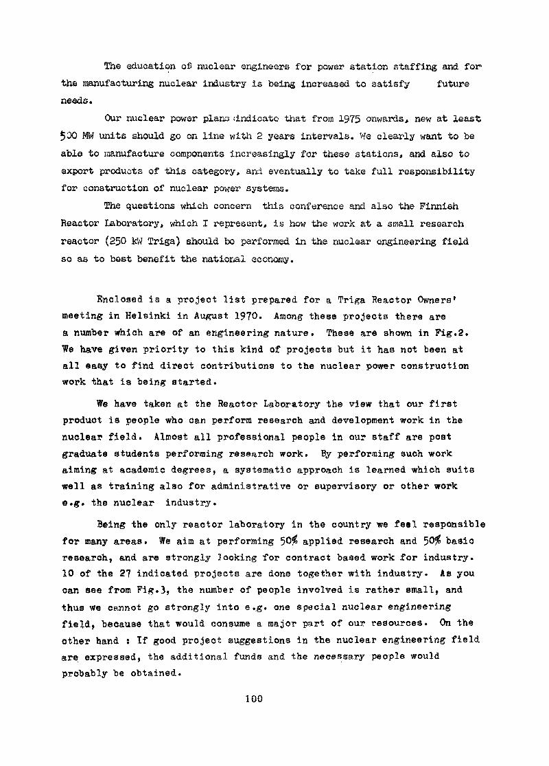
The education ofi nuclear engineers for power station staffing and for1the manufacturing nuclear industry is being increased to satisfy futureneeds4
Our nuclear power plans dndicato that from 1975 onwards, new at least$00 MW units should go on line with 2 years intervals. We clearly want to beable to toanufacture components increasingly for these stations, and also toexport products of this category, and eventually to take full responsibilityfor construction of nuclear power systems.
The questions which concern this conference and also the FinnishReactor Laboratory, which I represent, is how the work at a small researchreactor (250 kW Triga) should bo performed in the nuclear engineering fieldso as to best benefit the national economy.
Enclosed is a project list prepared for a Triga Reactor Owners1meeting in Helsinki in August 1970. Among these projects there area number which are of an engineering nature. These are shown in Pig.2.We have given priority to this kind of projects but it has not been atall easy to find direct contributions to the nuclear power constructionwork that is being started.
We have taken at the Reactor Laboratory the view that our firstproduct is people who can perform research and development work in thenuclear field. Almost all professional people in our staff are postgraduate students performing research work. By performing such workaiming at academic degrees, a systematic approach is learned which suitswell as training also for administrative or supervisory or other worke.g. the nuclear industry.
Being the only reactor laboratory in the country we feel responsiblefor many areas. We aim at performing 50$ applied research and 50$ basicresearch, and are strongly looking for contract based work for industry.10 of the 27 indicated projects are done together with industry. As youcan see from Pig.3, the number of people involved is rather small, andthus we cannot go strongly into e.,g. one special nuclear engineeringfield, because that would consume a major part of our resources. On theother hand : If good project suggestions in the nuclear engineering fieldare expressed, the additional funds and the necessary people wouldprobably be obtained.
100

Inspired by the aime.of this eonference, I sent some backgroundinformation of the conference and a list of questions to eelected keymembers of the Finnish Atpmic Technical Society. Some of.these questionsand typical answers-are sirown in Table I. T would like to point out thatwe have been acting for some years as if we knew the right answers tothese .questions, but certainly the resppnse we got will influence ourfuture research programming.
The contract for the first power station was signed a few months agoand a second one may follow within a year. At this time the problem areasrequiring local engineering research or barely training through researchwork can possibly be recognized better than earlier. It is still not easyto put basic engineering development work into systems which are built withthe responsibility for thé nuclear part resting with a foreign supplier.
In conclusion I will just nay what we typically would be doingin the nuclear engineering field based on the information I got before thisconference started from the inquiry. The R.L. would 'ask the FAEC permissionto start negotiations with the Finnish Atomic Industry Group and I.V.O.offering; the services of the R.L« in the fuel development area.
We would also try to got financing of.a study of small nuclearprocess heat supply systems.
This rather thin plan of action will certainly improve on the basisof information received here at this conference.
Table IInquiry among Finnish_nuclear experts concerning 'the roleof the Triga Reactor Laboratory in engineering subjects
Question.1 Should the Reactor Laboratory in Otaniemi aim at trainingpeople to be:good a) buyers, b) system designers, c) users, d) componentcontractors of nuclear power stations? and which is thepriority order ?
101
Answers ; - Good buyers are trained through activities aiming at b) and d)- Constructors should not be trained in tha Reactor Laboratory(R.L.)
• Training of users belong to the R.L.- Basic knowledge only can be given in the R.L.- Priority order b,c,a,d.
Question Should the R.L. start projects in the fields of a) reactor fueland material development, b) heat transfer and fluid flow,c) instrumentation development, d) reactor chemistry?
Answers; Primarily in a), possibly in c) and d) but not in b) as thisfield belon®to other disciplines.
Question... Is there some area in nuclear technology which is by far under-represented in Finnish R & 0 programs?
Answers; Several proposals which reflect the general shortage of competentnuclear engineers.
Question Into which project would you put available government funds?Answers : Fuel manufacture, small power reactors for process heat supplie-
and district heating.
Question Do you have any wishes concerning questions to ask the panelconference?
Answers: - How is the cooperation between the nuclear industry and aresearch reactor organized?
- How are the research projects started?- What is the relation between state financed and industryfinanced nuclear engineering development?.
- Are there any studies of small, low temperature heat produciirnuclear systems going on?
- Are there any systematic stuao.es of fuel handling methodsand equipment? field of
- Is anything done in the/ purification of radioactive gases?
102
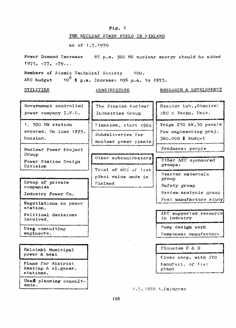
THE NUCLEAI< POWER FIELD IN .>'INLANDas of 1.7.1970
Power Demand Increase 8$. p.a. 500 MV nuclear energy should be added197 "5 —77 ~?QMembers of Atomic Technical Society 100.AEC budget 1G $ p.a. Increase 10^ p.a. to 1975.UTILITIES CONSTRUCTORS
Government controlledpower company I,V,G.
The Finnish NuclearIndustries Group
R ea ctor Lab. , 0 taniere::AEC & Te elm. Univ,
1 . 500 Mtf stationordered. On lin© 1975.Russian.
Nuclear Power ProjectGroupPower Station DesignDivision
Group of privatecompaniesIndustry Power Co.Negotiations on powerstation,
j Political decisionsI involved„j Useg consulting! engineers•
Helsinki Municipalpower & heatPlans Tor districtheating & el.gener.stations.Uaefi planning- consult-ants .
F irma torn,. s tart 1 966
Subdel ive.ri.es Tornuclear power plants
Other s-abcontra c-fcors
Total of 6O>' of î.-stpl'ant value made inFinland
Triga kfc%50 peoplePaw engineering1 pro j .360.000 $ budget
Produces: people
Other AEC sponsored
iïeactor materialsgroupSafety groupSystem analysis cFu e 1 manu f a c t u r « s t tid y
AEC supported researchin industryPump design workComponent manufacture-
Finira torn P. & DClose coop, with JVCManukact. or 1:stplant
.?.1970 \.Pa]m^ren
103
Fig. a
NUCLEAR POWER ORIENTED PROJECTS OF THE REACTOR LABORATORYIN OTANIEMI . FINLAND
t. REDESIGN OF COLD NEUTRON FACILITY
3. TEXTURE STUDIES WITH NEUTRON DIFFRACTION
5. DEVELOPMENT AND STUDY OF NEUTRON GUIDE TUBES
6. NEUTRON RADIOGRAPHY (NR>
7. CAPTURE GAMMA RAYS STUDIED FOR ANALYTICAL PURPOSES
9. SMALL ANGLE SCATTERING OF NEUTRONS
13. ON LINE PROCESS COMPUTER PROJECT
20. NEUTRON STOCHASTICS
22. REACTOR CODE DEVELOPMENT AND APPLICATION
104
Fig. 2QRQAHI3ATIOM OP THE REACTOR l ORATORY IN OTAKIBMI . FINLAND
MINISTRY OP COWŒRCE AND INDUSTRY
ATOMIC ENERGY COMISSION
TECHNICAL UNIVERSITY OF HELSINKI
OUt
CONSULTINGBOARD
Prof. L. SimonsMr. H.von BonsdorfiProf» P. HaapalaProf. V. HovlMr. 3. HultinProf. P. JauhoProf, H. Mieklc-ojaProf. J.K.MleHinonProf. P. Taslcinen
1SAFETY
COMMITTEEMr.O.VapaavuoriProf.K.SaUmSM[KrM.v.Bonsdorrf)Mr.B. Règne HMr.J.SaastamolnenMr, A. Vuorinen
DIRECTQ2REACT*
Î OP THEDR LAB
Prof. P. Jauho
BOARD OPDIRECTORS
Dr. A. Palmgren(vice-directorof R.I,,)Assoc.prof.S. TunkeloDr. J..KUU&IMr. A. TamjBinen
RESEARCH BOARDAssoc . prof .S. TunkeloDr. A, PalmgrenDr. J. Kuuai
Krs. 0, HoffrénMrs. M.-L. Kuula«rs. K. RyBti
t8K5E,AaCHDIVISION
Dr. A.PalmgrsnDr.W.D.Selffert
IAPPtIgP_RADJATION A ISOTOPES, DIVISION
Dr. J. Kuusi
Jfir.A.LundanMr.P.HautojarviKr.J.JunttllaMr.H.P8yryMr.H.Reljonenftr.R .HautakosklKr.H.OJaniemlItr.M.leikkonenHr.R.MSkelS
RADIOISOTOPBSAPPtlCATIQN
Dr.J.Kuusl
ACTUATION- ——— • —— •ANALYSIS^ * "^ — R—Kr.E.H&SJinen
suBcamcAi.ASSBMSLYDIVISION
I !OPERATIONS RAOIATIOH REACTOR
Mr.K.Anttila QIVISIONKr.O.Tiainen „_
fe.A.ïllttaJîr.J.Johansson
PROPyCTIONMr.R.UhlenlusHr.H.KuoppamJilti Mr.B.PalmenMr.E.Llndegren _„ .«nT » .Kuy KBUifcA AD Hr.jr.AlttomSkiKr.M.Savlranta Mrs.Hiss H.Puumala X.Ii.Kuutscbin
Kr. N.JaatinenMr. B.LlnâforsMr. E.SchultzMr. H.Virtanen
Mr.J.VaurioMr.H.SirkiS «P.
A.Tcnsninen J.Saestamoln«nHr.E.Kaloinen
Hr,E.MarkkanenMr.E.Pletartn^n«r.E.SavolainenMrs.A.L.fldSKSsoaHrs.S-LSSveri
Kr.J.SlllanpSSHP.

Appendix
Research Projects at ,jthe_ .Helsinki
I . Redesign of cold neutron facility2. Inelastic neutron scattering studies3« Texture studies with neutron diffraction4. Heavy water at anomaly point5. Development and study of neutron guide tubes6. Neutron radiography (PR).7. Capture gamma rays studied for analytical purposes8. Study of ftragg cut off in aluminium9. Small angle scattering of neutrons10. Determination of Planck's constant (planned).11. Hydrogen single crystals (planned).12. Study of phase transitions in solid methane (planned).13- On line process computer projects]4. Positron research (lifetime t 2- % angular correlation measurements), c _. . , , (Momentum , angular correlation of positroniumI1?. Positron research - >/ -111 ±- \3 - Q annihilation)16. Nuclear spectroscopy17. Radiation damage in semiconductorsifi. Pulse neutron research]Q. Neutron rethermaliastion20. Neutron stochaatics21. Nuclear noise studies22. Reactor Code de vei opinent and application23. Development of methods and apparatus for instrumental
analysis using radioisotopic methods
106
24. Tracer studies of processes in industry25. Activation analysis26. Study of methods for labelling with isotopes27. Dilution cryostat for polarization experiments
Questions nnd/or Comments
Your establishment is involved in such matters a<* productionof radioisotopes, activation analysis anf3 related activities. Isthe Center petting any financial return for those abovementionedservices from industry or anybody e]se who helps to contribute ssa service to the costs of your establishment ?
We are trying to get financing from industry? at present10 percent of the budget is financed with service charges but thisis expected to be increased to about ^0 percent during the nextfive years.
A remark- was mf.ee regarding the programme for fabrication offuel elements. Tt was pointed out that launching a fuel elementfabrication programme requires g créât deal of caution nnd i* canbe difficult, unless very much is known in advance about it.
It is true thnt this is a very large question, we startby interesting some students in the subject and we hope that afterthey h=ve been ir. the laboratory for two years, they will go outinto industry where very much money would be invested if thisproject was undertaken, b\H' we must do this in order to haveinterested and qualified people to start with.
107
EXAMPLES OP THE USE OF LOW-POWER REACTORS
FOB STUDYING PROBLEMS CONNECTED TO DEVELOPMENT AND OPERATIONOF POWER REACTORS
K. SaltvedtAktiebolaget Atomenergi
Sweden
Abs tract
The report p-5 ves a b r i ^ f def>cr. i n t i o n of some experiments which h.T/ebeer. performer in the s w i m m i n g pool reactor H?-0 ir.d the hightenperatur-e, crntica". •?ac i .1 i - f y K^fTZ.
The experiments are chosen to i l lus t ra te that 1 ov/ powermight be used for n t a d i e s of mar..y import ,ar t problem.-1, connected
g and operation of power reactors.
A summary of experiences gained from experiment . ,^ in the heavy watermodern ted critical f a c i l i t y RO 1^ also inc luded.
Introduction
A substantial part of experimental studies supporting the developmentof Swedish Power Reactors has been performed in low-power researchreactors. The first one, Rl, which was moderated with heavy water andwith fuel elements of metallic natural uranium, was brought inoperation in 1954 and was in continuous operation except for shutdowns for maintenance until the final close in July 1970.
A D_0-moderated bare critical facility, the RO, taken in operation in1959 was the second one. This has been shut down since 1969.
A swimming pool reactor, R2-0, taken in operation in 1960 was thethird one. This reactor is still in exstensive use.
The latest one which is a zero-power high-temperature critical facilitycalled KRITZ, designed for operatingcritical for the first time in 1969.called KRITZ, designed for operating temperatures up to 250 C, went
The advantage of using low-power reactors is the simplicity and lowcosts of the experiments. In contrary to the problems of handling and
109
transporting equipment irradiated in a. high flux reactor, whichrequires heavy shielding casks and hot cel.ls, the equipment in a low-power reactor might easily be taken out for modification or adjustments.
This report gives a brief description of some experiments which havebeen performed in the reactor B.2-0 and the critical facility KRITZ.The experiments are choosen to illustrate that low-power reactorsmight be used for studies of many important problems connected tobuilding and operation of power reactors.
As an appendix is also included a brief summary of experiences gainedfrom experiments in RO with references.
Experiments in the R2-0 reactor.
The R2-Q reactor shown in fig. 1 is a conventional swimming poolreactor, using MTR elements. The pool dimensions are 3 x 6 m andthe water depth is 9 m.The reactor is mounted in a tower suspended from a bridge structuremovable on rails both laterally and longitudinally in the pool. Thisarrangement makes it possible to place the reactor in any positionin the pool. The reactor is cooled by natural convection, whichlimits the power to 1 MW. Due to the limiting capacity of the poolwater cooling system, this power level can only be maintained for afew hours.
The reactor has been used as neutron sources for comprehensiveexponential experiments with different arrangements of full scalefuel elements for Swedish power reactors. The experiments havecomprised measurements of
form factorsmaterial bucklingconversion ratiosspectrum indices
110
The following parameters have been varied with different latticearrangements :
void constantdifferent types and arrangements of absorbers in the latticecontent of burnable poison in the rods.
The fuel elements in the form of square boxes of aluminium containing8x8 fuel rods, were arranged vertically in a 3x3 configuration. Thereactor was lifted and placed in a special supporting frame above thefuel assembly. The experimental arrangement with the provision for voidgeneration is shown in fig. 2.
Measurements of radial and axial neutron flux distribution havebeen made with neutron threshold detectors and by movable boroncounters placed on two sides of the fuel assembly. Fig. 3 showshow the boron counters are arranged. The blanket of stainlesssteel rods surrounding the core supresses the transients fromthe reflector.
Fig. 4 shows another arrangement which has been used in connectionwith criticality measurements of bundles of full scale powerreactor fuel rods. The problem was to evaluate the criticalityrisk associated with actual storage and handling procedures offuel rods at a reactor station.
The use of R2-0 as neutron sources for exponential experiments ofdifferent kinds has been very successful. An experiment with afacility like this should in many cases be considered as analternative to complicated calculations with high consumption ofcomputer time.
Reactor_chemistrv_j|tudies.Fig. 5 shows the equipment used for the studies of deposition ofcrud on @-radiating surfaces with variation of the pH-value ofthe water, conductivity, B~current intensity, temperature, etc.The 3-current emission was obtained by coating the actual fuelcanning material with Rh on the inner side of the pipe.At present an experiment is conducted which is part of a compre-hensive study of means to reduce the corrosion and transport of
111
corrosion products in a boiling water reactor. It is well knownthat NH, has this effect, bat to obtain, optimal effect the radio-lytical processes must be better known and controlled. The objectof the experiment is to clarify the relation between the radiationinduced processes in water and the ionization density.
The energy deposition, spectrum might be varied e.g. by addition ofB or Li acids to the water. The reaction B(na) Li or Li(na) His giving recoil particles with high ionization density.À sketch of the very simple in-pile part is shown in fig. 6. Thispart consists of a closed tube of stainless steel with the sameshape and size as a fuel element and has provision for circulationof gas and water. The nitrogen, hydrogen and oxygen content isdetermined with gascromatographical analyis. Determination is alsomade of the anion and cation nitrogen conductivity.
Neutron_radiogra£hjrThe easy access to the core and the absence of shielding problemsdue to the water, makes the swimming pool reactor specially suitableas a source for neutron radiography. A lot of neutron radiographicalinvestigations with equipment of different shapes for specialpurposes have been performed' in R2-Q. The methods have been provedto be very efficient for condition control and nondestructiveinvestigations of irradiated objects. As an example can be mentionedperiodical inspection of fuel samples during irradiation, accuratedetermination of the location of thermocouples, determination ofchanges in insulating gaps, detection of voids and levels ofmetallic coolants in radioactive rigs and capsules etc.It shall also be mentioned that a great interest has been shown fromindustries and research institutions for utilization of the instrument.
Radiation shielding^studies.
The great major part of experimental radiation shielding studies inSweden has been performed in the R2-0 reactor. Even if the existingmethods for shielding calculations give satisfying accuracy in mostcases, there is still need for experimental efforts in this field.Of the practicle problems which will be studied shall be mentionedthe shielding properties of complex geometris and material combinationsfor shielding of fast reactors.
112

Utilization of the High-Tempefature : Zero-Power Reactor KRITZ.KRITZ was originally built as an exponential facility for bucklingmeasurements at operating temperature on assemblies of full scalefuel elements for Swedish D^O power reactors. During the years ofoperation, a large amount of very valuable information concerningcharacteristics of different core configurations and verificationof theoretical models and calculational methods have been collected.
The use of an exponential facility is, however, limited to almostfundamental reactor physics studies. By modifying the facility to
- (allow critical core configurations» a much wider range of possibi-lities to experimental studies was opened. The facility is verysimple and flexible. It can serve as a partial mock-up for anyspecial power reactor of the light water type by using full scalefuel assemblies and control rods (or. true dummies).
The reactor system is designed for a pressure of 50 bar and atemperature of 250 C. In the reactor vessel a closed anular tankis inserted and its inner walls form a square core box. Thearrangement is shown in fig. 7 and 8. The reactor has no controlrod drive mechanism. The criticality is controlled by regulatingthe water level in the vessel. By special arrangement with quickopening valves, water can be drained from the core box to theinsert tank. The arrangement makes it possible to lower the waterlevel in the core box to half dump in less than 1 second.
Fig. 9 shows the circulating and auxiliary circuits. The system ispressurized with nitrogen gas. Zil is the feed water storage tank.The water temperature in the storage tank and reactor vessel iscontrolled independently by the electrical heaters El and E3respectively. The water level in the reactor vessel is controlledby the feed pump B2 and the control valve A178 in association witha variable restriction for filling, and the valve A179 for draining.An air cooled heat exchanger providing cooling capacity' 2°C/min.
113

CostsThe cost of original pressurized exponential facility wasapproximately 1 million dollars. The additional costs for modifi-cation to a critical assembly were approximately 0,3 milliondollars. This does not include costs for the fuel, as the facilityso far has been oper'ated with fuel manufactured for the differentpower reactors under construction. The operating cost of the facilityis mainly determined by the man power cost and thus by the intensityof utilization.
The experimental program for the next few years will be focused onproblems of great importance for further developments and approve-ments in operation and construction of the reactor types of interestin Sweden.The preparation and execution of the program is made in close contactwith the reactor industries within the country as well as with thepower utilities.The studies will compris:
reactivity measurementsmeasurements of power distributionsstudies related to in-core instrumentationstudies of flashing during pressure drop transients.
The following parameters will be varied:enrichmentcore configurationtemperaturevoid contentboron content in watersolid absorbers in fuel and water
Measurements_of reactivij:v_coef f icients.The temperature dependence of the reactivity of a power reactor isstrongly unlinear and there is still a lot of uncertainty in theability of the existing calculational methods to predict the differ-ential effects on this relation.
114

It is of great importance for a safe and economical operation of thereactor to bring this uncertainty down to a minimum for all modesof operation. Changes in the core with considerable influence onthe reactor physical paramets (configuration, control rod arrangement,burnable poison, Pu-fuel etc.) will specially emphasize the importanceof these measurements.As an illustration shall be mentioned that the insertion of boron ina PWR is limited by the phenomen that the moderator coefficient isturning positive. Another illustration of actual problems whichrequire comprehensive experimental studies is the cooled start up,which means that the reactor system is brought into full power operationwithout external heating.
Measurements of p_ower distributionThe uncertainty in the calculated hot spot factors might in many casescause considerable power limitation. One problem illustrating this, isthe so called mismatch factor. As a result of refueling or shuffling,large differences in enrichment between fuel pins facing each othermight occur. It is of great importance from economical considerationand for the efficiency of the shuffling program to have accurateinformation about the local disturbances in the power distribution asa result of the mismatching. Empirical information about this conditionis considered necessary to give satisfying accuracy. Design studies ofimprovements in core configurations and control rod shapes and arrange-ments also call for further empirical efforts in this field.
StudLesrelated toii c o r instrumentation.The importance of safe and economical operation of reliable in-coreinstrumentation is well emphasized by all reactor operators. Thesimplicity of the facility makes it easy to study the applicationof different types of in-core instrumentation.The experimental program comprises evaluation of the relation betweenmeasured values and required information in any mode of operationtaken into consideration disturbances and influence factors ofdifferent kinds.
115

The plans for this experiment are preliminary and have not beenanalyzed in all aspects so far. The back-ground for the experimentis the condition which arises in a power reactor when a suddenpressure drop occurs, due to for example safety valve operationor pipe break. It is of vital interest to verify especiallythe heat transfer calculations but even reactor physics paramets.
116
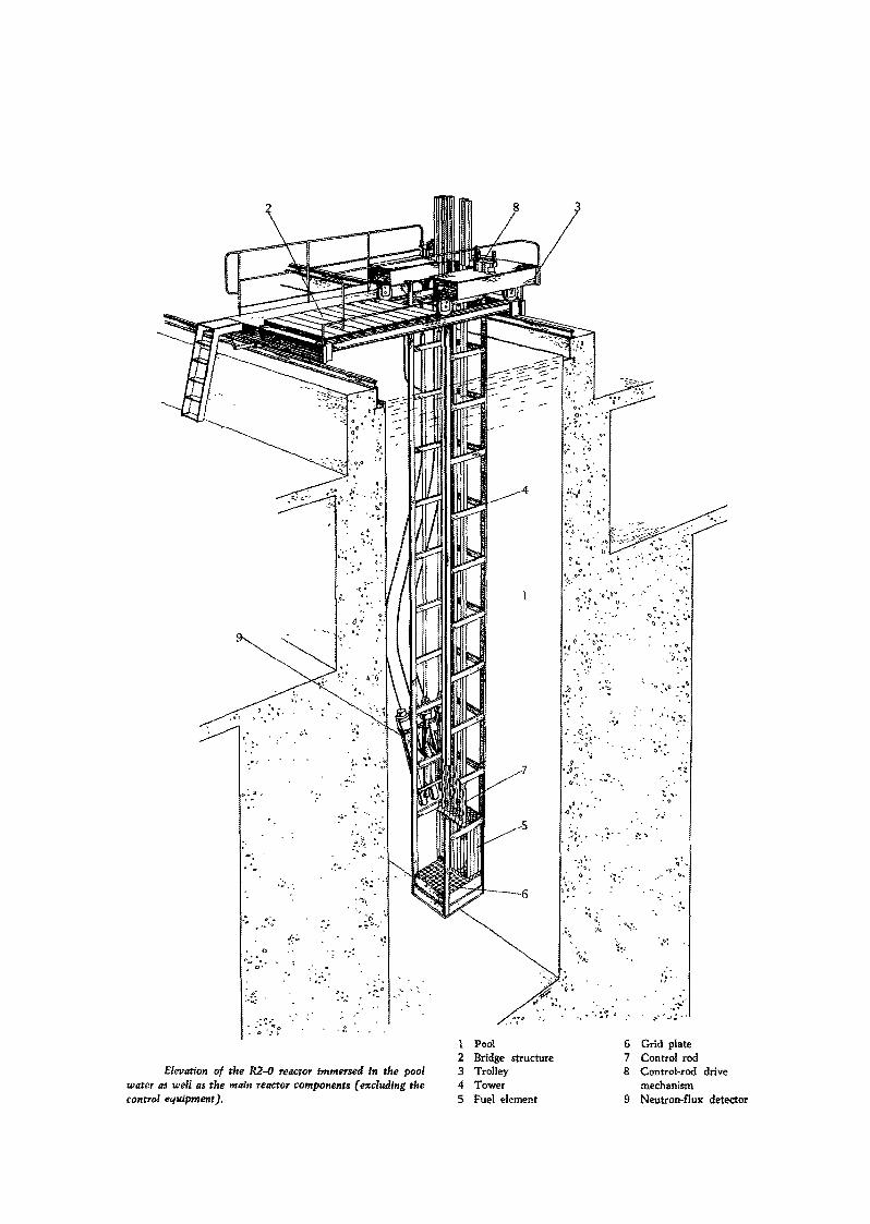
Elevation of the K2-0 reactor Immersed in the poolwater as well as the main reactor components (excluding thecontrol equipment).
1 Pool2 Bridge structure3 Trolley4 Tower5 Fuel element
6 Grid plate7 Control rod8 Control-rod drive
mechanism9 Neutron-flux detector
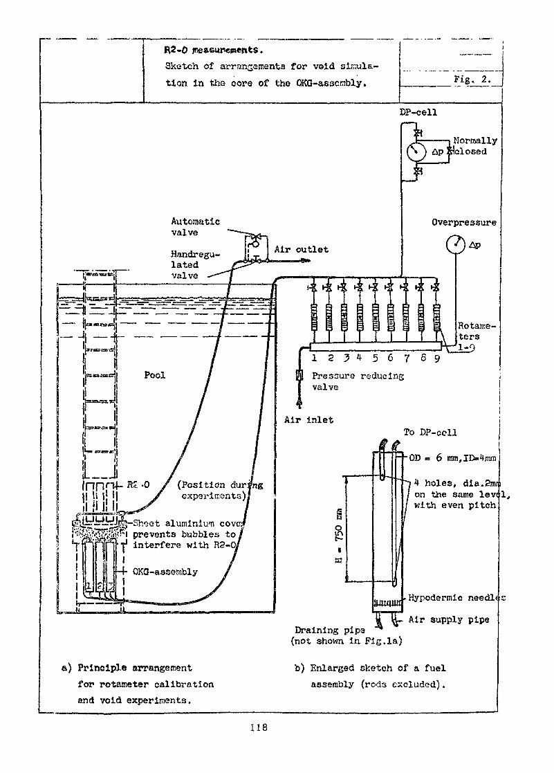
Sketch of arrangements for void sircula-tion In the core of the OKQ-aescmbly. Fig, 2.
DP-cell
AutomaticvalveHandregu- H/ir °Utlet
latedvalve
rO A p l tNormally
tlclosed
Overpressure
Rotame~ter s
1 2 5 4 5 6 7 8 9| | Pressure reducing
valve
To DP-cell
holes, dia.2mrion the same levwith even pitch
(Position durexperiments)
t aluminium cov» ; ! prevents bubbles to
interfere with
Hypodermic needltc
Air supply pipeDraining pipa(not shown in Fig. la)
Principle arrangementfor rotameter calibrationand void experiments.
b) Enlarged sketch of a fuelassembly (rods excluded) .
118

Fig. 3
Detector
Stainlesssteel rods
Fig. 3. Fuel arrangement and drive mechanism for- boroncounters with measurements on QKG-elements.
119
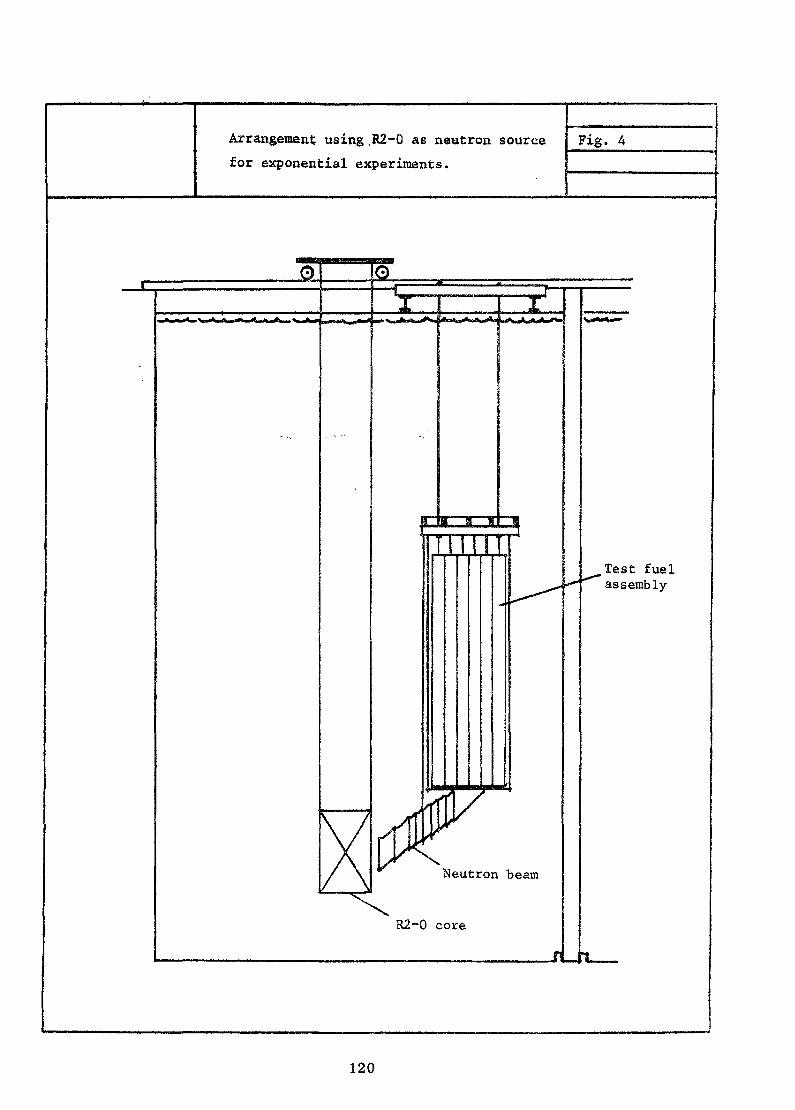
Arrangement using .R2-0 as neutron sourcefor exponential experiments.
Fig. 4
0 O<ViXjjiVJ>_iA
nu
d'wA.jre^wn.
Neutron beam
R2-0 core
Test fuelassembly
120
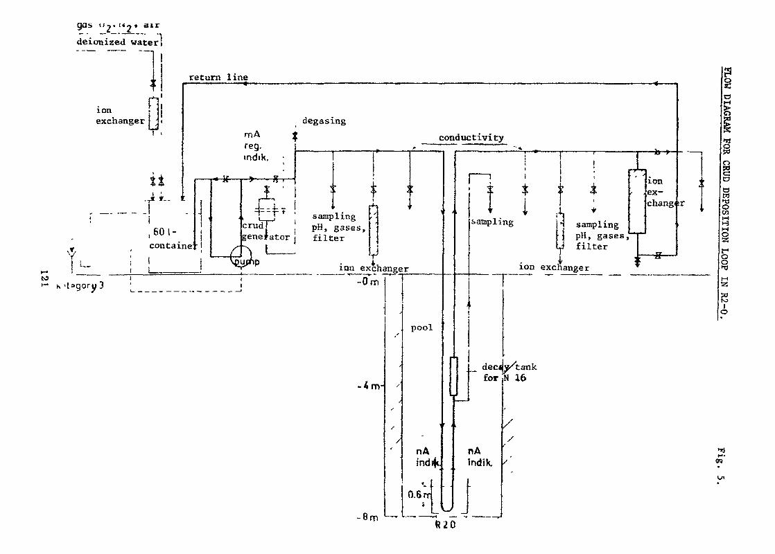
gas i /2« Mo
deionized water]
. . return 1 ine< , ———————— « ——— — — , ———————— • ————————
nion .exchanger J ; i degasing
T. rr,A ireg.mdik. • j: i
U , —— i« K i > —— S-r- |I1' ' ^ ' iC ^
-T* i- •: r-i-, " t1 J 4—tt * El J
.' ~s "j , ,, ; ! ' samplingen i ! crudj PH, gases, '
1 i generator filtercentaine -1 /- -\ 11 ' / i — • — • ,. i
i 1 1 Voupnp . it L_ ' ^"^ lnn exchanger' ' nry 3 |_ _j -um
,
i ,
-4m-
- f t m
.'
/
^
S
f
/
^
rk
conductivity"•^
pool
nAind
*_
0.6 rr*
•
t.
^r
>
o
iJ.
1 — !î îsampling
\1
11
1M
'
)
'
|1
t
1
*
samplingpH, gases,filter
-
ion exchanger
decsfor
nAIndik.
v/tankN 16
//
'
•>
b -»•••
ionex-chang*
y
- ———— ,
1i
r
r
go>o
o
asGDDEPOSITK
g•HD
-12<o
O
•nTO
^
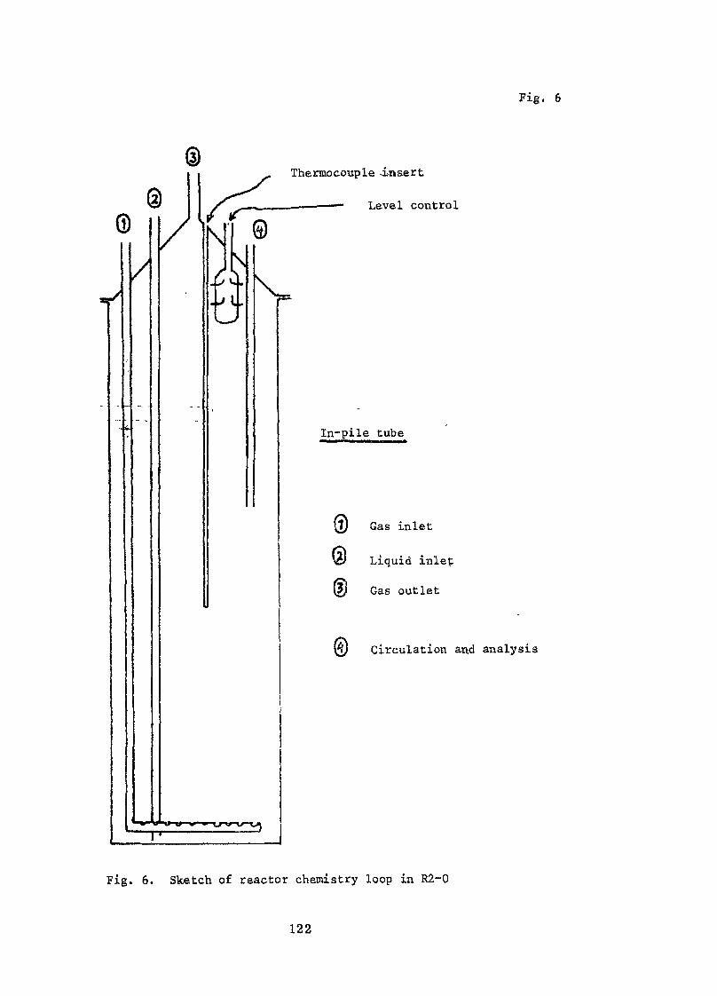
Thermocouple -insert
.————— Level control
\V
In-pile tube
Fig. 6
(l) Gas inlet
ic/ Liquid inlet
(2y Gas outlet
m Circulation and analysis
Fig. 6. Sketch of reactor chemistry loop in R2-0
122
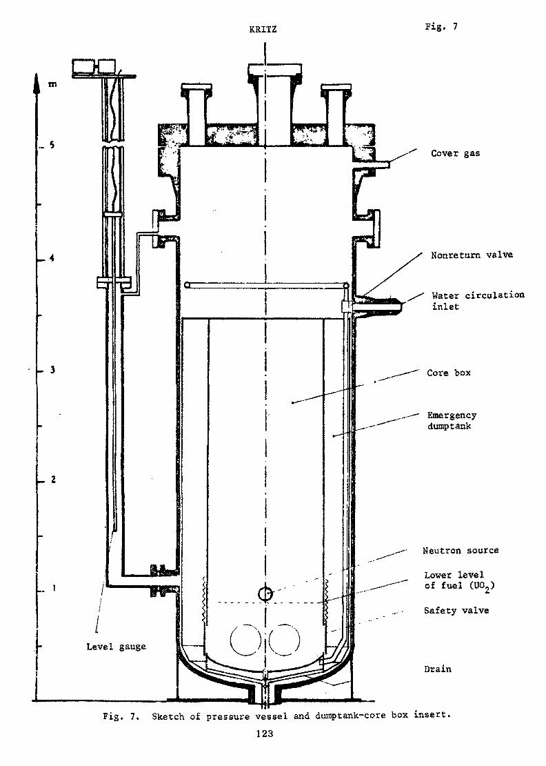
KRITZ Fig. 7
Cover gas
Nonreturn valve
Water circulationinlet
Core box
Emergencydumptank
Neutron source
Lower levelof fuel (U02)
Safety valve
Drain
Fig. 7. Sketch of pressure vessel and dumptank-core box insert.123
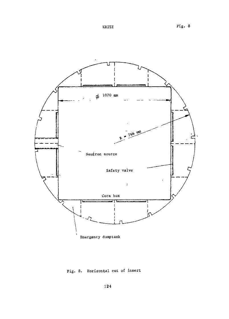
KRITZ Fig. 8
Emergency dumptank
Fig. 8. Ho-riEontal cut of insert
124
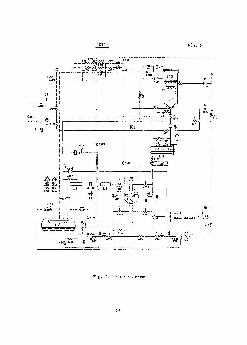
KRITZ Fig. 9
Aît1A262T*»S A2KP.J.-O*^
.Fig. 9. Flow diagram
125
Appendix.
Summaries of experiences from experiments performed in thecritical facility RO. Studsvik
collected by Rolf Persson, AB Atomenergi.
The critical facility RO [1] was brought to eritieallty for the first timein September 1959. It was built for measurements on DO moderated lattices.Since clean experimental conditions for buckling determinations were consideredto be quite essential, it was decided not to use any graphite reflector, atleast not during an initial period. Owing to the good experiences of the bareassembly we have still no graphite and we are more than ever convinced thatthe original decision was far-sighted.
Features which have been of'great importance for obtaining good experimentalresults are summarized below.
a) Flexible, simple and still accurate fuel-suspension system.
b) Piston arrangement for continuous level control.
c) Turnable lid giving good access-to the whole tank area..<•>!
d) Water-level meter with an accuracy of 0.1 mm.
e) Linear differential recorder of the power level.
f) Safety rods movable to arbitrary radial positions.
g) Motor-driven -carriage for radial detectors or.samples.
h) Central tank-bottom tube convenient for oscillation experiments.
Amongst experimental equipment we may also mention resistance thermometers (Pt)with a resolution of 0.01 C, expansion end 'plugs for fuel pins used inactivation experiments [ 2], pulse-counting equipment checking its own dead-time continuously [3J, pneumatic values for empty-tube experiments [4], bubble-producing device for void experiments [5] and flexible pile-oscillatorequipment.
126
Most of the time has been devoted to buckling studies, both with full criticalloadings and'by using the substitution technique. The last method has beeninvestigated in great detail [6] [7] [8] [9] [10] . The progressive form ofthe substitution technique is found to be quite powerful. By using (maximum)only 1/10 to 1/4 of the core volums, we are able to get buckling values withthe same accuracy as from full-loading experiments. Such good results areobtained thanks to the use of a bare assembly. The temperature coefficient ofbuckling has been studied up to 80°C [ 9] . A lot of experimental bucklingresults were reported at the Second Panel on Heavy Water Lattices 1963 [11],and also at the IAEA symposium in Amsterdam 1963 [ 10] . Results from measurementson uniform and mixed lattices of single rods of UOp and ThOp rods werepresented at a thorium conference in Gatlinburg, May 1966 [12].
In connection with progressive substitutions the effect of differences indiffusion coefficients have been studied by means of single fuel assemblies[ 8j [9] [ 10] [ 11] . Anisotropy in the neutron diffusion can be determinedquite well (within 1 to 2 per cent ) by that method [13] .
The effectiveness of control rods has been studied extensively as functionof various parameters [ 14] [ 15] . Differences in spectrum sensitivity betweenabsorbing materials of various composition have also been investigated bycomparing the reactivity effects of plates of various thicknesses [16] .The experimental values on control rod worths have been well correlated bymeans of a second-order perturbation-theory approach taking interaction effectsinto account [17] .
Lattice cell characteristics, such as fine structure, spectrum indices(thermal and epithermal), fast fission and conversion ratio, have been studiedby means of activation techniques for a variety of fuel compositions, latticepitches, temperatures and void fractions [12] [18] [19] [20] [21] . To get highspatial resolution we have sometimes used a precision roller for making thinbands of activated wires, e.g. Cu. [22] [23] .
The pile-oscillator technique has been studied [ 24] [25] [26] and used inseveral investigations where weak samples are involved or small differences inneutron reacting properties are to be determined with the highest possibleprecision [ 27] [28[ [29} [30] [31].
127
Experiments have also been performed in collaboration with other laboratories.Fuel charges for the Boiling Heavy Water Reactor in Halden have been investi-gated in our critical and exponential assemblies [ 32] [33] • An exchangeprogramme with the Savannah River Laboratory resulted in buckling measurementson metal tube elements [34] « Swedish-made UO^ fuel ordered by the Swiss centerat Wlirenlingen has been used for buckling intercalibration with the Swissexponential assembly MINOR [ 35] •
References:
[1] Landergârd, 0., Cavallin, K. and Jonsson, G.The Swedish zero power reactor RO.AE-55 (1961).
[2] Olofsson, 0Expansion p!TPM-FFR-46 (1965) (memo in Swedish).Expansion plug for temperatures up to 235 C.
[3] Persson, R.Evaluation of axial measurements in TZ.TPM-FFR-9 (1965).
[4] Olofsson, 0.Test on pneumatic valve for fuel assemblies.TPM-RFXO-32 (I960) (memo in Swedish).
[5] Andersson, A.J.W. and Wikdahl, C.-E.Equipment for producing controlled void in a fuel assembly and somemeasurements of void fraction.FFR-45 (1966).
[6] Persson, R.Measurements of buckling by means of the substitution technique.RFX-46 (I960).
[7] Persson, R.Eccentric test regions in substitution measurements.RFX-70 (1961),
128
[8] Persson, R.One-group perturbation theory applied to substitution measurements withvoid.AE-250 (1966) (rev. ed. of AE-72 (1902)).
[9] Persson, R., Wikdahl, C.-E. and Zadw6rski, 2,.Critical and exponential measurements on 19-rod clusters (R3 fuel) inheavy water.Nukleonik 4 (1962) 191-199-
[10] Persson, R.The evaluation of buckling and diffusion coefficients from two-regionexperiments.Expo, and Grit. Experiments, Vol. Ill, (pp. 289-304) IAEA, Vienna, 1964.
[11] Persson, R., Hellstrand, E. and Johansson, E.Experimental reactor physics work on heavy water lattices in Sweden.Heavy Water Lattices, Techn. Reports Series No. 20, (pp. 305-342), IAEAVienna, 1963.
[12] Sokolowski, E.K. et al, - .Experimental studies of mixed D_0 lattices containing Th02 ro.ds.Paper presented at the Second International Thorium Fuel Cycle Symposiumin Gatlinburg, USA. May 3-6, 1966.
[13] Persson, R.Semi-empirical formula for the change of diffusion coefficients causedby channels.JNE 20 (1966) 671-673.
[14] Bjoreus, K., Persson, R/. and Wikdahl, C.-E.Measurements of control rod worths in cirtical and exponential assemblies.Physics and Material Problems of Reactor Control Rods (pp. 173-201), IAEA,Vienna, 1964.
[15] Pekarek, H.Control rod measurements in the exponential assembly ZEBRA.TPM-PPR-18 (1965).
129

[16] Persson, R.Intercomparison between various control rod materials.TPM-FFR-33 (1965).
[17] Persson, R.The interaction between control rods as estimated by second-order one-group perturbation theory.AE-250 (1966).
[18] Sokolowski, E.,and Wikdahl, C.-E.Measurements of fine structure and spectral indices in lattices ofMarviken fuel assemblies.FFR-47 (1965).
[19] Sokolowski, E.Different activation techniques for the study of epithermal spectra,applied to heavy water lattices of varying fuel-to-moderator ratio.AE-230 (1966),
[20] Pekarek, H. and Wikdahl, C.-E.Measurements of relative conversion ratio, U-238/Cu-63 reaction rateratio and fuel fine structure in Marviken type lattices.EFR-50 (1966).
[21] Pekarek, H. and ffauffin, L.The fast fission-correction for RCR measurements in Marviken boilerelement lattices.TPM-FFR-39 (1965)•
[22] Wikdahl, C.-E. and Âkerhielm, F.Measurements of disadvantage factors in a small mock-up.Proc. Second UNICPUAE 12 (pp. 377-379), Geneva, 1958.
[23] Olofsson, 0.Investigation of the rolling-cut of activated copper and gold wires,TPM-RPX-135 (1962) (memo in Swedish).
[24] Persson, R.Elimination of aperiodic terms in pile-oscillator measurements.TPM-EFX-298 (1963) (memo in Swedish).
130
[25] Bliselius, P.-A. and Sjb'oquist, S.Method of -analysis and electronic equipment used for pile-oscillatormeasurements at BO.RFX-215 (1965) (report in Swedish).
[26] Bliselius, P.-A. and Pekarek, K.Method to analyse the periodic functions obtained from pile-oscillatorexperiments and computer programmes.
[27] Bliselius, P.-A.Pile-oscillator measurements on fresh fuel for the Agesta reactor.RPX-266 (1963) (report in Swedish).
[28] Sokolowski, E., Pekarek, H. and Jonsson, E.Cross section measurements for some elements suited as thermal spectrumindicators: Cd> Sm, Gd and Lu.Nukleonik 6 (1964) 245-251.
[29] Eriksson, B.Pile-oscillator measurements on ThOp.TPM-PFD-19 (1965).
[30] Eriksson, B.Pile-oscillator measurements on polyurethane material from Eidg.Institut fur Reaktorforschung, Wtirenlingen, Switzerland.TPM-PFD-20 (1965).
[31] Eriksson, B.Pile-oscillator measurements on material of current interest for theMarviken superheaters.TPM-FFD-23 (1966) (memo in Swedish).
[32] Per s son, R. and Standal, N.Measurements on spike elements in RO and HBWR.HPR-9 (1961).
[33] Smidt 01 sen, H.Reactivity test and exponential experiments with HBWR second charge fuelelements.
54 (1964).
131

Erlandsson, I. and Persson, R.Exponential measurements on the SRL four-tube fuel assemblies withvoid.RFX-89 (1962).
[35] Persson, R.Substitution measurements in RO with 37- and 19-rod clusters of naturalUOp 1.30 cm in diameter. (Experiments in collaboration with EIR,Wù'renlingen AG, Switzerland) .TPM-EFR-6 (1964).
132
SUMMARY REPORTOff THE USE OF RESEARCH REACTORS IN THE PROGRAMME
OP RESEARCH AND DEVELOPMENT OP MJCLEAR POWER IN
YUGOSLAVIA
N. RaiSià, Boris KidriS Instituteof Nuclsar Sciences, VinSa
Abstract
The main objective of the Research and DevelopmentProgramme for nuclear power in Yugoslavia is the developmentof nuclear fuel for the power stations "built in cooperationwith a foreign partner. This objective is described.An account of the use of the existing Yugoslav ResearchReactors in this programme is given.
The research and development programme of nuclearpower in Yugoslavia formulated in 1968 and approved in 1969 bythe Federal Scientific Board, has as a basis the followingassumptions ;
1. In a near future, but not before 1975, Yugoslavia willbuild the first nuclear power station in cooperation with
a foreign partner.
2. As a working hypothesis the power station will be of thenatural uranium D^O type, but the light water enricheduranium types are not excluded from the consideration.
3. Yugoslav industry and design organisations will be en-couraged to take, an active part in the design and theconstruction of the plant.
The above assumptions are realistic although thesecond one is not strictly formulated. This leads on the onehand to certain unprecision in the formulation of the researchprogramme, but on the other hand offers the possibility forappropriate changes if the situation requires.
133

On the basis of these assumptions the final goalsfor the R and D programme have been formulated,1. Yugoslav design organisations have to be in the capacity
to take an active part in the design of the plant. By de-veloping methods and techniques for calculation and designthis goal has to be assured. Even if this participationwill be modest for the first, it has to increase progressiv-ely for the succèsive plants.
2. Except for the fuel inventory and early supply of fuel fromabroad, the yugoslav industry has to develop the capacitiesin order to supply first and later reactors with the fuelfrom the domestic resources.
f3. Electricity generating company has to accept at an earlystage all responsibilities for the operation, fuel mana-gement and maintenance of the power plant.
4. A care should be taken to the development of control theoryand engineering, with possible application not only topower plant b,ut also to other industrial objects.
5. The development of the technical and administrative aspectsof reactor safety will be the care of nuclear research jinstitutes. r'
6. In the radiation protection, both methods and instrumentation' " have to" Be developed in order to assure, the safe and harm-
less operation of the power plant with respect to the ope-ration personal and surrounding residential area,
1 < iThe R and D programme is given in the form of a
number of separate projects which have their own goals and"i t,dynamics of realisation.For the fullfillment of the programme three nuclear
institutes are partially engaged (Boris KidriS Institute inBeograd, JoSef Stcfan Institute in Ljubljana and Rudjer BoSko-vic" Institute in Zagreb) and in'addition one design organisationand a few industrial laboratories.
134
Beside the other laboratory equipment the nuclearinstitutes dispose with three research reactors. Boris Kidriôhas a zero power reactor RB, and a 6.5 MW research reactor RAboth are heavy water moderated. The first one is a criticalassembly with a variable core configuration (1) using bothnatural and slightly enriched fuel. It is intended for criti-cal experiments, fuel and other nuclear material testing onpurity/ and kinetics experiments. Research reactor RA operatingof the power of 6.5 MW is mainly used for isotope production,capsule irradiation and solid state physics work.
Fuel element project incorporated in the power pro-gramme has a final goal the development of the technologyof fuel production. It includes all the phasis of the fuelfabrication process, starting from domestic ores, its concen-tration and purification, preparation of sintering grade UOj "sintering, fabrication of the fuel slugs up to its assemblingto cluster type fuel elements. Through all phasis of thetechnological processes the appropriate methods for materialand final product testing are applied. As particulary suitablefor nuclear purity testing in various phases of the process,reactor oscillator method is selected. To meet these requi-rements a reactor oscillator named ROB-1 (2) is installed onthe reactor RB. It has' boen extensively -used for the deter-mination of nuclear impurities in uranium and other reactormaterials.
The fuel element development programme requires anumber of determination of the reactor physics characteristicsof a fuel element as a whole. Due to the fact that the labora-tory technique is seldom in a position to produce more thanone fuel element of a type, it was necessary to develop anexperimental technique, for determination of the fuel elementparameters based on a single rod experiments. As representativeparameters of a fuel element characteristics, the neutron sourceand neutron sink have been selected, and neutron flux measu-rement around the fuel element in a large thermal pit insidethe RB reactor has been performed as a appropriate method todetermine these quantities (3).
135
Research reactor RA wUth a maximal thermal neutron13flux of the order of 6.10 and the fast neutron flux at some
positions in the reactor of the same order of magnitude, lenditselfs as a good tool for fuel irradiation in capsules, alt-hough it is not convenient for in-pile loop experiments witha complete fuel element, A particular advantage of the reactoris the hollow cylinder type of fuel element which allows theirradiation of the fuel pellets in a high fast neutron fluxwithout an additional effort for sample cooling. The capsuleswith fuel pellets are normally inserted inside the previouslyprepared fuel.cylinderf and irradiated with the fast neutron• • - • ' • ? 0 2fluence of the. order of 10" n/cm . During the irradiationprocess the fuel temperature is recorded using the thermo-couples. The capsule extraction out of the reactor and trans-portation, to the fuel testing cells involves no complications.
As already mentioned , .the- RA react9r does not pro-vide the possibility for complete fuel elements irradiation.To satisfy this need incorporation in some internationalproject has been envisaged. Particulary the. OECD Halden pro-ject is•appropriate for this purpose. The négociations withHalden project are in course.
Both SA and RB reactors are used for reactor kine-tics and reactor control study. The power plant control projectincorporated in the power programme has as one of its purposes.the study of the on-line digital control. To meet these needsthe process digital computer CDC-1700 is purchased and willbe used for the control study of the RA reactor. In the nearfuture, the indication of the off-line computer will be compar-ed with the normal reactor operation. Later on, the intentionsare to close the loop and submit the reactor periodically tothe direct on-line digital control. This operation will givethe informations on reliability of this type of control andthe behaviour of the instrumentation developed in our labora-tories, particularly the inter-phase instruments. -. ;-
Research reactor TRIGA-Mark II at the Institute Jo5ef/ • f
Stefan in Ljubljana is incorporated in the R and D research
136
programme in order to facilitate the study of shielding cha-racteristics of the various materials in connection with fastneutron penetration. Using the constructive characteristics ofthis type of reactor a fast neutron converter plate is insta-lled at the thermal column of the reactor. Special techniquesare developed for the determination of the fast neutronspectra. The same reactor has been used "for the testing ofthe control rod mechanisms developed by domestic industry.
At the present time the Research and DevelopmentProgramme is subject to revisions with the intentions to makeit up to date for the next three years period» Among othersthe final choice of the power plant type will be made and inconnection with this, a more precise formulations of the aimsof the fuel development project.
References
1. S.Jovanovié et al. s Sero Energy Reactor RB, IBK-2 (1963).
2. M.Petrovic" et al.s Pile Oscillator ROB-1, IBK-359 (1966).
3. N.Raiëié et a l . s Determination of Reactor Parameters bySingle Rod Experiment? Bull.Boris Kidric" Institute,Vol.20, Nucl.Eng.No 2 (1969) .
Questions and/or Comments
There are many activities being carried out in the Yugoslav researchreactors concerning engineering problems. Is this being done for generalunderstanding of reactor systems? for general background or do you havedefinite plans to participate in the design and construction of reactorcomponents in large proportion when you install the power reactors ?
Actually, this programme was approved in 1968. At that time we didnot know' a definite date for the construction of the first nuclear powerstation, but we envisaged 1975 as the approximate date. Now we are ina position to ask for international offers for a 600 MW nuclear powerstation. However» the electric utility company does not need very much
137

our institute in order to install the reactor. .Looking at what ishappening in the nuclear power world regarding nuclear fuel, andanalyzing the economics of nuclear fuel development versus nuclear fueloffers» it seems to be much better for the reactor operator company tobuy the fuel 'from manufacturers abroad and keep the fuel developmentactivity a Tittle lower until later on. The fuel activity shall be keptin order to have qualified personnel to be engaged later on in consideringthe possibility of dealing with fuel licenses to build perhaps a nuclearfuel factory in the country.
You have mentioned the possibility of having to reduce the nuclearresearch activities. Have you considered that non-nuclear research isbeing done in nuclear research organizations, such as Harwell and manyothers afld that it may be worthwhile to consider this ns qn alternative4o reducing the total volume of research ?
Yes, this is actually the case, as I mentioned at the end of mypaper, there is some intention to more or less orient our institute'sactivities towards some other fields. The engineering department which ismainly dealing with heat transfer hydrodynamics and related fields caneasily be reoriented towards the direction of conventional power plantsor other sort of equipment needed by the industry. A rather large laboratoryis presently devoted to the nuclear fuel element programme, most of thepersonnel in this laboratory have skills in dealing with 'ceramics, they canbe devoted to the fabrication of electronic components.
The personnel engaged in control theory are now more active in thedirection of system analysis in general, and control theory applicationto normal engineering processes. There are really no big problems ofreorientation but it is still very complicated to transform the activitiesof an institute which has been working for more than 10 years in one givendirection, just to orient it in another one; the problem of financingarises. We will have to encourage financial cooperation from industryand then the next question is : 7/hat kind of a programme can industrysupport ? It should be a long term programme since the change ofactivities in an institute like this is not a matter of a few months,it is rather a matter of planning for something in the order of 5-10years.
All these problems are not yet solved but I am just raising aquestion which may be worth being discussed in this panel»
138
INDIAN NUCLEAR EFFORT - STATUS REPORTby
S.M.Sundaram, N.Veeraraghavan and M.Ranganatha RaoReactor Operations Division
Bhabha Atomic Research Centre, TrombayGovernment of India
Bombay, IndiaJuly, 1970
A B S T R A C T
The Department of Atomic Energy has programmed to install 2700 MWeof nuclear power generating capacity in the country by 1900. In additionto (a) the two reactors (2 x 200 MWe, GE-BWR, TAPS) already in operationat Tarapur (Maharashtra), (b) the two reactors (2 x 200 MWe, &tNDU-PHWR,RAP? I and II) in an advanced stage of construction at Kota (Rajasthan)and (c) the two more reactors ( 2 x 200 MWe, CANDU-PHWR, MAPP I and II)approved for Kalpakkam (Tamil Nadu) and work on which has commenced, itis proposed to augment the nuclear power generating capacity by 1500 MWeby constructing advanced thermal reactors of up to 500 MWe unit size.
The engineering facilities available at Bhabha Atomic ResearchCentre, Trombay, and the manner in which they have grown and led to thesetting up of various plants elsewhere in the country in the context ofthe country's nuclear effort, have been highlighted. The emphasis placedon the development of indigenous know-how and creation of ability tosolve technical problems with minimum foreign assistance, has not onlyprovided a strong engineering base required for the nuclear power pro-gramme, but also has acted as a catalyst in the scientific and techno-logical advancement of the country.
139
INDIAN NUCLEAR EFFORT - STATUS REPORT
The Department of Atomic Energy has programmed to install 2700 MWeof nuclear power generating capacity in the country by 1900. In additionto (a) the two reactors (2 x 200 MWe, GE-BWR, TnPS) already in operationat Tarapur (Maharashtra), (b) the two reactors (2 x 200 MWe, C^NDU-PHWR,fiAPP I and II) in an advanced stage of construction at Kota (Rajasthan)and (c) the two more reactors (2 x 200 MWe, C*NDU-PHWR, SUPP I and II)approved for Kalpakkam (Tamil Nadu) and work on which has commenced, itis proposed to augment the nuclear power generating capacity by 1500 MWeby constructing advanced thermal reactors of up to 500 MWe unit size.
2. The Indian nuclear energy programme was started with an awarenessof the problem of lack of adequate industrial base and the necessity ofcreating a cadre of trained scientific and technical personnel. Enumeratedbelow are the problems we have encountered and methods adopted for provid-ing not only the necessary man power but also the engineering facilitiesrequired to sustain the nuclear power programme envisaged. This approachhas acted as a catalyst in the scientific and technological advancement ofthe country.
3. Our national centre for nuclear science and technology, the BhabhaAtomic Research Centre, was started in a modest way with a scientific andtechnical staff of about 130 in 1954 and has gradually grown to a staffstrength of over 6000 to day. It has been possible to create this cadredue to the setting up of the research reactors and other facilities atTrombay, the emphasis placed on the development of indigenous know-how andthe encouragement given to local talent.
4. AS a first step, the swiimiing pool reactor, PS-aftA, was commissionedin 1956. Except for the fuel, which was obtained from U.K. on hire, thereactor was designed and engineered at Trombay. The years I960 and 1961
140

marked the commissioning of two more research reactors, CIRUS and ZERLBlA,the former built with Canadian assistance. This led to the setting up ofplants for production, fabrication and reprocessing of fuel. Other faci-lities such as plants for reconcentration of heavy water and radioactivewaste management were also built. Research groups in basic and appliedsciences have grown with the setting up of the facilities mentioned above.Thus, Trombay provided not only a strong engineering base for embarkingon a nuclear power programme but also an impetus for research in basic andapplied sciences.
5. Nuclear technology or for that matter any new technology in adeveloping country is handicapped because of the substantial financial andtechnical investments involved and the non-availability of supportinginstitutions capable of undertaking developmental effort in conventionalengineering which is possible in a highly industrialised nation. Theabsence of a basic industry not only leads to the non-availability ofback up technology but also explains the absence of generation of largescale capital which can be invested in the development of nuclear technology.In the Indian nuclear power programme the emphasis has always been on thedevelopment of indigenous know-how and creation of ability to solveproblems in the context of local conditions „ Such an approach has enabledgeneration of self-confidence and also the ability to engineer and executeprojects with minimum foreign technical assistance,
6. The first nuclear power station at Tarapur was constructed andcommissioned as a turn-key project. Indian personnel took part in siteselection, tender evaluation and pre-construction safety evaluation.Trombay was responsible for the manufacture of control panels, healthinstrumentation, dummy fuel assemblies and start-up sources, nn independentsafety evaluation of the Station during commissioning was carried out by
141
ci team of senior scientists from Trombay. The station went into operationin April, 1969 and since turn over in late 1969» is being manned entirelyby Indian personnel.
7. It has been possible to contribute in a larger measure for thelater power stations by way of indigenous production of various components,e.g., up to 36$ for RaPP I and 60$ for EUPP II. It is anticipated that theindigenous components for the Madras power station will be increased to 80$.The construction responsibility for RAPP rests with Indians whereas for theMadras power station, design and construction responsibilities are, completelyIndian.
8. Based on pilot plant studies of the HJS-H.O exchange process carriedout at Trombay, a 100 Te/year. heavy water plant is being constructed nearKota. Another plant with a capacity of 60 Te/year is also under constructionat Baroda. These will be in addition to the existing DO plant in theNangal Fertiliser Complex.
9.. A uranium mill for the beneficiation of Indian ore has been set upon the basis of experimental work carried out in Trombay. *. nuclear fuelcomplex to manufacture pewer reactor fuel elements and special materialsis expected to go into production shortly.
10. It was realised from the beginning that a strong base in electronicsis essential for the development of any nuclear power programme. Startingfrom the control system for psara, our efforts in electronics grew steadilyto such an extent that it became necessary to set up a commercial unit,Electronics Corporation of India Limited,for production of quality electroniccomponents and equipment necessary for a nuclear power programme. It is ofinterest to note that control instrumentation for R PP I and II and flUPP arebeing fabricated by Electronics Corporation of India Limited.
142

11. With the limited resources of uranium and plentiful supply ofthorium in India, it is advantageous to embark on fast breeder reactortechnology for a sustained nuclear power programme. With this in view,a decision has been taken by the Indian Atomic Energy Commission to setup a fast breeder test reactor in the Reactor Research Centre beingplanned at Kalpakkam, Tamil Nadu.
Questions and/or Comments
You mentioned that in India the conventional technology hasprofited from the nuclear research. India is a country which hasinvested very much into the nuclear field, but I wonder whether thiscould be extrapolated to a more general theme, since in other casesthe effort is first concentrated towards the development of conventionaltechnology in areas other than nuclear, and also <r +hat way, 3t ad-vances the technology of the country. T can hardly see that India'sapproach of concenti-pting 8 large effort OK nuclear development is ingeneral a line to follow for a developing coun+T<;y.
As I mentioned, the nuclear power development does mean con-currently the developmer-1- of conventional engineering in India, "butI suppose this is also largely true in any developing country. Toreally get into the nuclear business, the investment must "be madeand it shall be viewed in the context of the benefit that the countryis likely to accrue, since it is our experience that not enough in-formation is normally obtained to even fabricate components. If youcontinue to import and buy the designs from other countries, there isalways a commercial aspect that comes in and it does not help to pro-mote the development of technology in one's own country. T believe,there is no other way but to invest in a large measure as we have done.I suppose this is true for all the countries similarly placed.
143
AECL'S ENGINEERING PROGRAMS IN RESEARCH REACTORS
by
J.A.L. ROBERTSONAtomic Energy of Canada LimitedChalk River Nuclear LaboratoriesChalk River, Ontario, Canada
ABSTRACT
Experience has taught us the value of well designed research reactors.These should be associated with versatile facilities for the fabrica-tion and subsequent examination of test specimens. The facilities cangrow with the program and even the reactor can evolve as required.The experimental program, if judiciously selected, can be of immensevalue in either of two ways:
By providing, in miniature and at an early stage, almost all theproblems to be met in designing and commissioning a power reac-tor.By developing the necessary expertise to formulate a nationalprogram for nuclear power.
Paper prepared for discussion by IAEA Panel on Engineering Programs inResearch Reactors, Vienna, 27-31 July, 1970,
AECL'S ENGINEERING PROGRAMS IN RESEARCH REACTORS
INTRODUCTION
In education there is a distinction between teaching facts and impartingwisdom based on experience, or in modern terms between data-acquisitionand problem-solving. Most of the IAEA's meetings are largely concernedwith the first function, exchanging results by technical papers, but thispanel has the much more ambitious objective of showing how past experiencecan benefit those now undertaking engineering programs in research reac-tors.
145

Youth claims that it must be allowed to learn by its own mistakes and thatnobody over 25 can be trusted. Now that the Chalk River Nuclear Laborato-ries have celebrated their Silver Jubilee, Canada has joined the oldergeneration: Thus we feel compelled to offer advice, realizing that coun-tries still young in atomic energy will regard our words with scepticism.However, we believe we are somewhat wiser now than we were before our 25years' experience. It is our hope that by sharing the lessons from thatexperience others may be able to reach the same stage in a much shortertime» We also expect the discussions will contribute to our own continu-ing education.The lessons we have learned can be divided into those relating to thefacilities (hardware) and those relating to the programs using thesefacilities (software).HARDWARE
The research reactor with its irradiation facilities is the largest singlepiece of hardware, but it is by no 'means all that is involved in an irra-diation program. Provision must"be made for fabricating and testingspecimens before they are irradiated and for examining them in hot cellsafterwards. At both Chalk River and Whiteshell we are very fortunate inhaving the fabrication laboratories and the hot cells within a few hundredmetres of the experimental reactors.The major'advantage of such close proximity is that the individual respon-sible for any Gxperiment has direct control over all aspects of -it. Also,since he can be present in person the flow of information to and from himis not subject to the delays and attenuation of less direct forms of com-munication'. As an example of the benefits, the experimenter can bç. con-sulted immediately on what action should be taken when unexpected -condi-tions prevail during an irradiation. Similarly, when anomalies areobserved during post-irradiation examination, the person who prepared thespecimens can assess exactly what changes have occurred during irradiation.To take full advantage of the compact siting there must be a parallelwithin the organisation with those responsible for fabrication, irradia-tion and examination all operating within the same unit. This combinationof conditions- provides the be.st communications and the maximum flexibilityto allow for unanticipated events.The type of reactor that is good for physics experiments, e.g., neutronspectrometry, is not necessarily ideal for engineering programs. Further-more, there are different requirements for testing fissile and non-fissilematerials. The fast neutron flux is the primary requirement in studyingthe performance of, non-fissile structural material's and» generally, thehigher the flux the better so that several decades1 experience in a powerreactor can be simulated in a few years in the experimental reactor.' Intesting fuels, however, it is the thermal neutron flux that is important(unless, of course, the fuel is intended for service in a fast reactor).
146

The maximum thermal neutron flux required for fuel testing is usually lit-tle inare than that to be encountered in Service. This is because acceler-ated burnup can be achieved only by increasing the power density so thatthe fuel dimensions have to be scaled down to prevent excessive fuel tem-peratures. An ideal experimental reactor for engineering programs mighttherefore have a maximum thermal flux of several times 1014 n/cm s, and aregion or inserts capable of providing a high fast neutron flux. For mostpurposes a somewhat lower thermal neutron flux can be compensated by addi-tions of fissile material to the test specimens.The constancy of neutron flux in space and time is much more important inthe testing of fissile than non-fissile materials. Phenomena of interestin non-fissile structural materials are rarely affected significantly byvariations of, say, 10% in the flux. Thus two non-fissile specimens canbe compared even if they have been irradiated at positions of slightlydifferent flux. With fuels, however a 10% variation in thermal neutronflux can have approximately the same percentage effect on temperature dif-ferences within the fuel. When one is concerned with a phenomenon charac-terized by a high thermal activation energy, e.g., the migration of fis-sion product gases in UOg, these variations can have a very serious effecton the results. The same 10% variation in flux would affect the processnearly an order of magnitude for an activation energy of 75 kcal/mole.Thus, a good reactor- for experimental fuel irradiations should have notonly a relatively constant flux but also a large volume of uniform flux toallow valid comparison of different specimens. A large reactor core alsomakes for easier provision of the access paths needed for leads and con-nections to the test site. At the other end of the connectors, space mustbe allowed in the reactor building for ancillary and control equipmentwhose total volume is many times that of the reactor core. In all theserespects, as in many others, we have been particularly fortunate with ourexperimental reactors, NRX(!), NRU(2> at Gialk River and WR-l(3) at White-shell .It is worth remembering that the experimental reactors themselves are notimmutable but can evolve with the experimental programs they serve. TheNRX reactor was originally fuelled with natural uranium metal. Later itused natural UÛ2 and is now fuelled with enriched uranium in an aluminumalloy. As a result of these and associated changes the thermal neutronflux has been increased by a factor of nearly two. When the calandria ofthe KRU reactor is changed in 1971 provision will be made for increases inthe number and size of the experimental facilities. So far, the WR-1reactor core has contained 37 fuel sites cooled by two separate circuits.A development program will increase the number of sites up to 54 with theintroduction of a third coolant circuit. Also, changes in fuel and cool-ant tubes will increase the thermal neutron flux by about 50%. Thus, pro-vided one starts with an experimental reactor capable of serving the engi-neering program for a foreseeable future there need be little fear of itsbecoming obsolete.
147
Most of the hot cells at Chalk River and Whiteshell, and their method ofoperation, have already been described(4-6) f r e cost of such installa-tions can be very large and the operating expenses high, but all the cellsdo not all have to be provided at the start. Granted sufficient foresightin the initial planning, it is possible to expand the facilities asrequired by the program. Initially, we found it possible to do all thework for a small experimental program in a single hot cell by movingequipment in and out as required. A hot cell is the most convenient sin-gle facility for performing all aspects of post-irradiation examination,but in an ideal arrangement hot cells should be complemented by othertypes of facility. Underwater examination is not only cheaper for simpleoperations but allows us to examine fuel elements and return them to thereactor during a normal reactor shutdown when heating due to residualradioactivity would prevent dry examination in a hot cell.Where continuing and frequent use of a particular piece of apparatus isenvisaged it can be more efficient to design the shielding around theapparatus. We adopted this principle for the metallography of activespecimens. Since these specimens are relatively small their activity iscorrespondingly lower so that much more compact shielding is possible.Even small boxes shielded by lead blocks can be used for specific opera-tions. A microbalance within shielding approximately 0.5 x 0.6 x 0.4metres('» ^) yielded density measurements on 100 mg samples cut from U^Sifuel elements irradiated to > 10,000 MWd/tonne U. Small samples need onllight shielding during thinning for transmission electron microscopy^»replicas taken even from fuel samples can be cleaned of adhering activecontamination, then handled normally(**).In exactly the same way there should be a variety of in-reactor testfacilities complementing each other. These would include small and largefuel testing loops(12), hydraulic "Rabbits"U?)t fuel sites with enhancedfast neutron flux, unfuelled loops for studying structural components,coolant and moderator. Here too the initial investment need be only mod-est with the facilities being augmented as the program develops. However,there is a strong argument (see section on software) that at least one ofthe facilities should be £ fuelled loop.Six of the loops now in NRX were originally built as pressurized waterloops and were installed during the period 1954-1956 when several organi-zations were designing water-cooled power reactors. Loop X-4 was suppliedby the UKAEA* and the others by the USAEC*. AECL* shared the installationcosts and hence the usage of these loops. The USAEC now occupy X-l andX-3 while AECL occupy the others.
UKAEA = United Kingdom Atoric Energy Authority.* USAEC = United States Atomic Energy Commission.* AECL = Atomic Energy of Canada Limited .
148
The X-4 loop was converted from pressurised water to superheated.steam in1961 and then to fog coolant in 1963. It is now able to handle any ofthese three coolants. In 1963 the X~6 loop was converted to handle boil-ing water with a steam content up to 30% by weight. The other loops stilluse pressurized water as coolant but. they have all been improved in vari-ous ways since originally being installed. For instance, the X-3 loop nowhas two in-reactor test sections in parallel.In 1960 when the attractions of organic liquids as power reactor coolantswere becoming apparent, AECL built and installed the X-7 organic-cooledloop in NRX. The last NRX loop, X-8, which was installed in 1964 containsno nuclear fuel and was built to study the behaviour of a water moderatorunder irradiation.The NRX loops are of relatively small diameter; X-5, the largest, is capa-ble of taking a maximum fuel diameter of 5.6 cm. Thus loops X-l throughX-7 have been mainly used for the irradiation testing of single elementsor of small clusters of elements. Prototype testing of full size -fuelbundles has been conducted in the much larger NRU loops.The in-reactor test sections of the U-l and u-2 loops were both 8.25 cminternal diameter when originally installed. However, their bores wereincreased to 10 cm diameter to provide appropriate test sites when wedecided to use the, larger diameter pressure tubes in our power reactors.U-2 is a pressurized water loop with a heat removal capacity of 3.5 MW.U-l can use steam, fog or boiling water as coolants and has a heatremoval capacity up to 4 MW depending on the coolant. Much of the devel-opment work on fuel and fuel channels for the CAKFDU* Boiling Light WaterReactor at Gentilly(14) was clone in U-l. U-3, an organic-cooled loop, isthe larger version of X-7. It has recently been modified to be capable ofhandling "simmering" organic with a heat removal capacity of 6-7 MW.Finally, in NRU is the U-5 loop which provides hot pressurized water toany lattice position. The various in-reactor sections are used to studythe effects of irradiation on different properties of non-fissile mate-rials, e.g., corrosion, creep and stress rupture. There is no fuel withinthe test sections but each is surrounded by a ring of fuel elements (fastneutron rods) to enhance the fast neutron flux at the specimens.Our third experimental reactor for materials testing is the WR-1 organic-cooled reactor at Whiteshell. Since the coolant is operated at elevatedtemperatures characteristic of power reactors, experimental fuel bundlesand coolant tubes can be tested in regular sites without provision of spe-cial loops. The reactor coolant is divided into two separate circuits(three in future) permitting independent variation of the coolant condi-tions for experimental purposes. TWO fast neutron loops, IL-4 and IL-5
* CANDU Reactor = The Canadian power reactors using jDeuterium (heavywater) moderator and natural Uranium fuel.
149
(with a third, IL-6 scheduled for 1971) provide facilities comparable tothose of the U-5 loop in NRU. The IL-2 loop is a boiling water loop forfuel testing. The original design of WR-1 was tested in the X-7 and U-3loops but subsequent development has been performed largely in WR-1 it-self. Thus, the coolant outlet temperature has been progressivelyincreased from about 350°C, steel pressure tubes are being replaced byzirconium alloy ones and the possibility of replacing the present UÛ2 fuelwith one capable of providing a higher thermal neutron flux is beingexamined(15^.SOFTWARE
The software consists of the engineering program that uses the researchreactor. Historically, most countries' early programs for their researchreactors have been concerned with pure science, in the traditional disci-plines,of physics and chemistry. Only later, as plans for generatingnuclear, power were formulated, have the applied engineering programsdeveloped. The result has been in many instances that the engineeringprogram has had to accommodate to an organization and a reactor that wereoriginally intended for other purposes. Only the richest countries canafford a new research reactor for a new engineering program. The firstlesson is, therefore, that the research reactor should be conceived anddesigned with a clear appreciation of the probable engineering programs.The design of a large power reactor is an awe inspiring undertaking, ifthe designers proceed in isolation they cannot help but produce an uneco-nomic reactor, overdesigned to compensate for their lack of practicalexperience. Meanwhile, the experimentalists who could have provided theexperience have been working on other interesting but irrelevant problems.ftn engineering program in a research reactor confers immeasurable benefitsby forcing early recognition of the critical problems? by providing afocal point on which to concentrate the energies of several diverse disci-plines; by demonstrating the need for certain interdisciplinary skillsthat are often missing in organizations modelled on a university pattern;and by requiring the management structure necessary for directing a proj-ect that cuts across traditional departments. Indeed, a well conceivedfuel irradiation in a reactor loop is a microcosm for a power reactor.In a fuelled loop it is obvious that the behaviour of the fuel materialitself is being rested, and it soon becomes apparent that the propertiesof the sheathing material are just as important. However, the selectionof sheath is controlled partly by the environment in which it must oper-ate. The nature of the coolant, e.g., water, gas or liquid metal, hasprobably been established independently, but its pressure and temperaturemust depend in some way on the containing vessel. Also the chemical con-trol of the coolant must be such that it is compatible with the ex-reactorcircuit» Thus each component interacts with others and cannot be selectedor tested on its own. Too often these interactions are not fully appreci-ated until they are encountered in practice.
150
Specifying the fuel assemblies for the irradiation test involves the sameskills that, are required in designing the power reactor. Reactor physicscalculations are needed to establish the fissile content of the fuel whileheat: transfer calculations define the conditions to avoid certain physicallimitations by acceptable margins. New methods, including computer pro-grams, will usually have to be developed for these calculations and someancillary experiments may be required to verify them. The ostensibleproduct of the calculations is the design for a loop test but just asvaluable is the acquisition of personnel and techniques suitable for per-forming the calculations for power reactors.Similar benefits are gained from the construction of hardware for thetest. Translating an ideal design into a practical and economic productrequires experience and expertise that are more often found in industrythan in university or government laboratories, A proper appreciation offabrication tolerances may necessitate some reassessment of the design.Thus construction of the fuel for a loop test is an appropriate time atwhich to involve commercial fabricators. Not only will the design gainfrom their experience but also they will gain invaluable understanding offactors affecting the design.In the past most deductions about fuel performance have been made by com-paring observations before and after irradiation. Nowadays, however,techniques are available for making certain measurements during irradia-tion. The use of miniature pressure transducers incorporated into theend-plugs of actual fuel elements has shown us how the fission productgases are released from UC>2 during power changes 116). Similarly, straingauges have been used on the sheaths of operating fuel elements; as manyas 14 gauges per element to give a comprehensive pattern of the strain H 7).Although the output of these gauges may drift unreliably over periods ofdays to weeks, much valuable information has already been obtained onsheath strain resulting from power changes in Zircaloy-sheathed UO0 fuelelements> Another very useful instrument in fuel irradiations is theself-powered neutron flux detector(18), which is the size of a thermocou-ple and just as convenient to use. These and other instruments can nowprovide as much information from a single test as would have been obtainedfrom a whole series of tests earlier.While concentrating or* wnat is being put into the loop it is easy to for-get the wealtn of information available from the operation of the loop it-self. Our c&NJDU-type power reactors with their pressure tubes can bethought of as an assemblage of loops connected to a common external cir-cuit. Thus a great deal of the experience obtained on loops is of directrelevance to the pcwer reactors„ indeed, a major attraction of our systemj.f researcn and power reactors is that practically all features of thepower reactors can be tested in the research reactors,The ecor.onu.co of the power reactors depends on the thickness of the pres-sure tubes which, i~ tar:., is a function of the creep strength of thepressure tube material un dear service conditions. Uniaxial creep tests can
151

De easily done in the laboratory but a biaxial stress system, as found inpressure t;ubes, and irradiation damage both affect the creep, behaviour.tfe have found that the most direct, and therefore in the long run the sim-plest, way to determine the appropriate creep properties for pressuretubss is to measure the progressive increases in diameter ;of,pressurecubes in pur experimental loops. Very accurate gauging equipment has beenSeveloped to measure the inner diameter of the pressure tube at a reactorshutdown, when the fuel is removed: Ancillary controls make the gauge headtraverse the tube, compute the readings and plot the results as strains (19).To provide accelerated tests and to study the effect of varying stress onbhe creep rate certain lengths of the tube are machined down to differentthicknesses. Measurements of this type have shown how the strain ratedepends on the fast neutron flux, the stress and the temperature for both£ircaloy and Zr-2,5 wt% Nb(20), These results provided the informationlecessary to design pressure tubes for our power reactors and are findingcontinued application in a surveillance program on selected tubes in thesower reactors.Coolant chemistry is another vital subject that has been studied in loops.First it was established in pressurized water loops that control of the pHbo a high value suppressed corrosion of steel components of the primarycoolant circuit outside the reactor core and, thus, avoided heavy deposits3f corrosion products on the fuel sheaths(21). Additions of LiOH were -ased for this purpose. Additions of hydrogen (or deuterium) serve to keepthe coolant reducing, even in the presence of radiolysis in the reactor:ore, so that corrosion of the zirconium alloy components is maintained ata lew level,(2£) . All this was proved out in test loops of the NRX reactorDefo.re power reactors were built. Other loop tests have established howadditions of ammonia can reduce the corrosion of zirconium alloy compo-nents, in boiling water systems (2*).
teny of the experiments in the large loops of NRU are concerned with vari-ous aspects of heat transfer — such as determining the degree of coolantnixing between subchannels and establishing the conditions leading to dry-DUt cf the fuel sheath(24)t Much of this work is still largely empiricaland therefore has to be performed on the actual geometry of the fuelassemblies for the power reactors. A closely related subject is thevibration and fretting of the fuel assemblies. Some aspects of heattransfer and vibration do not require in-reactor loops but, when one isSealing with several megawatts, even a laboratory simulation can be diffi-cult and expensive. In.the final analysis, some questions can be answeredjrily by an in-reactor test.performing experiments in the reactor in preference to the laboratory is arecipe for saving time, manpower and money that may seem surprising.Almost every group has followed the same sequence of measuring a particu-lar property first on the unirradiated material, then on the same materialifter irradiation and only finally during irradiation. When this lastaeasurement is available the others are virtually ignored and need neverlave been done (except for screening tests, staff training, etc.). The
152
literature on nuclear materials is full of examples of work that is inter-esting in its own right but which designers disregard as soon as they haveaccess to results from an experimental reactor, e.g.,
Measurements of the thermal conductivity of UOp as a function of tem-perature.
- Studies of rare gas migration in U02« (During irradiation the gas isdriven back into the solid creating a completely different situation.)Measurements of creep and aqueous corrosion for zirconium alloys.(For both, properties an alloy that is worse than another in the labo-ratory may be the better when both are compared during irradiation.)
Obviously, the laboratory studies contribute useful background knowledgebut, if savings have to be made, it is the in-reactor experiments thatshould be retained.In one most important respect our programs have been specially fortunate :They have enjoyed the helpful cooperation of skilled and efficient person-nel operating the experimental reactors and associated facilities. Whilethere is no way to achieve this happy situation by legislation the.organi™2ational structure should be such as to minimize friction. For both irra-diations and subsequent examinations we have put the better establishedand more routine aspects with the Operations staff and the more explor-atory and experimental aspects with the Research and Development staff.With such a structure the interface between the two groups assumes a cru-cial role.In Ï959 with AECL well embarked on the design of the Nuclear Power Demon-stration reactor, a new organizational unit, the Loops Branch, was set upat Chalk River, The more obvious purpose of this Branch was to coordinateactivities concerned with the in-reactor loops and thus facilitate theirradiation testing of the fuel» However, it also provided much of theexperience and development necessary for power reactors. Its structureconsisted of three sections; Installation and commissioning, loop develop-ruent and chemical. In the first of these an engineer would be assigned toany new loop that was committed. He would-follow its progress from thedesign through the commissioning to operation. The development sectionvas concerned with improving the performance of instrumentation and compo-ne:.t.s. AIL matters pertaining to the chemistry of the loop coolant weretrie responsibility of the chemical section. Staff from other countriesoperating loops at Chalk River, i.e.., the United States and the UnitedKingdom, were integrated in this Branch. Today the Loops Branch has asomewhat changed role but its original purposes, now applied to powerreactors, are being continued on a much larger scale throughout AECL.
Even bureaucracy, if properly controlled, can contribute to an engineeringprogram. We have a committee that reviews experiments proposed for theresearch reactors, assesses their worth and recommends priorities. These
153

are Useful functions but the committee makes its greatest contributionbefore it ever meets, by requiring the experimenter to document his pro-posal. The discipline of stating explicitly the objective and means ofachievement, cogether with the resulting discussion from recipients of thereport, often improves the experiment. Also, a recipient sometimes seesways of making use of the same experiment to give additional results of•value to his own program. The same proposal report is later useful to thereactor operating staff in showing the conditions required for the testand the actions to be taken in certain eventualities.Our early experience taught us that sometimes a vital piece of informationwas not available when the time came to examine an irradiated specimen.This is perhaps not surprising for an experiment that can occupy severalyears from initial proposal to final interpretation. Nowadays, each sepa-rate experiment is assigned a file number coded to show the reactor andloop in which it will go. Each stage in the progress of the-experiment isdocumented by informal internal memoranda assigned consecutive serials inthe appropriate file. Thus, anyone concerned with the experiment, e.g.,reactor supervisor or hot cell technician, can easily lay hands on allavailable information, in view of the expense of these experiments inboth money and time we have deliberately made very detailed records ofspecimens before irradiation(25)} since missing information can never beobtained later.CONCLUSIONS
This concluding section will attempt to summarize those factors we con-sider important to any engineering program in a research reactor.The first essential is a good research reactor, good for the purposeintended. Also required are other items of hardware: Facilities for fab-ricating specimens, irradiating them and subsequently examining them.Since these can, to a large extent, be modified and increased to match anexpanding program the reactor itself is the most important single item,and should be designed with sufficient spare capacity to accommodate mosteventualities. Justifying the expense of such a reactor is normally dif-ficult at a time when there are insufficient programs to occupy it fully „•This is when the sale of isotopes and the rental of irradiation space toother organizations can provide useful revenue. A research reactordesigned for engineering programs is rare and should not be short of cus-tomers .Our own experience supports this contention. Initially in NRX, NRU andWR-1 our engineering programs were in the minority with other countriesparticipating in collaborative programs. With the advent of economicnuclear power our programs have expanded and we now largely occupy allthree reactors. Although we need the space we regret the consequentreduction in exchanges, since we gained much more than revenue from ourcollaborative programs. With a cooperative program for irradiations,exchange of information and experience is not only facilitated but practi-
154

cally inevitable. Thus, at an early stage of development, before commer-cial competition is intense, the joint use of a research reactor is per-haps the most effective means of sharing costs and achieving internationalcollaboration.However small it starts, the engineering program should, ideally, be rele-vant to some clearly defined purpose, e.g., the design of a power reactor.In tackling the experimental irradiation one meets, in miniature, almostall the problems that will have to be solved in the major project. Usu-ally a reasonable experiment performed early is much more valuable than abetter plan-ned experiment performed a few years later: Unexpected problemscan be identified in time for a solution to be found. Indeed, any rele-vant program can be counted on to provide an endless supply of topics forfurther research.Alternatively, an engineering program in a research reactor can be used asa nucleus on which to grow a national program. For this purpose it isfortunate that a world-wide shortage of long-term research and developmenton in-reactor phenomena has resulted in several potentially rewardingproblems not being tackled adequately. Those building power reactors havefound empirical solutions for their immediate needs without gaining abasic understanding applicable under, different conditions. By working onsuch problems anyone with, access to a suitable research reactor can soonbe'leading current research, instead of merely following. The expertisedeveloped in performing the experimental program and the interaction withothers interested in the results will be invaluable in formulating thenational program.Even a superficial review of the various types of power reactors willquickly identify several fruitful topics for basic study:
The effects of fast-neutron and fission-fragment damage on creepbehaviour.The effects of reactor irradiation on corrosion, considering both thephysics of the solid and the chemistry of the coolant fluid.Mechanisms for mass transfer of activated corrosion products in thecoolant. ,Improved methods for predicting heat transfer and vibration of fuelassemblies, of more general applicability than, are at present avail-able.The effects of very high vacancy concentrations,, .the formation ofvoids .and bubbles, and the consequences of these defects on the mate-rials' properties.The nature of irradiation damage in various graphites as a function oftemperature.
155

;.igineering /programs in research reactors are no different from any other>rogram in applied science in one respect: The work is useless until it istigested and communicated to someone who can use it. However, the long:ime-seale of most irradiation experiments} the limited control of someexperimental variables and the number of people that can be involved make.or unusual difficulties. Thus, special consideration of the recordingind reporting of results is justified. Furthermore, the expense of thisrork and the difficulty of exactly reproducing conditions makes open pub-.ication of the techniques the only efficient means of operation.'his finally brings us to an area in which the IAEA can contributeiirectly. The value of any in-reactor experiment is very closely related;o the degree with which experimental variables are controlled and known*Reliable techniques are available for the in-reactor measurement of cer-:ain variables, e.g., neutron flux, temperature and gas pressure, but theyire used all too rarely. As a result many expensive irradiations cannot>e interpreted, or have no general relevance. There have been severalmeetings and exchanges on this topic, but under the sponsorship of differ-ent organizations and without coordination(26). The Agency might, through.ts Secretariat or a small panel of experts, compile and publish a cata-.ogue of in-reactor measuring techniques, comparable to the existingdirectories of reactors. Those seeking to use a new technique would then«low to whom to write for information and advice. Periodic symposia, pos-sibly organized on a regional basis, would naturally complement such acatalogue. In the nuclear community there is a great fund of goodwill,just waiting to be tapped, among the older generation towards the young.REFERENCES
(1) Manson, R.E. and Smyth, H.E. "The NRX reactor - a general descrip-tion", Atomic Energy of Canada Limited Publication AECL-2692 (1967).
(2) Manson, R.E. "The NRU reactor (1964)", Atomic Energy of Canada Lim-ited Publication AECL-1897 (1964).
(3) "WR-1: Unique among research'reactors", Canadian Nuclear Technology,4, 4 (1965) 30.
(4) Ananthakrishnan, S. "Remote handling facilities at Chalk River",Atomic Energy of Canada Limited Publication AECL-1658 (1962).
(5) Bain, A.Sr, MacDonald, R.D., Kerr, D.B., Kelm, J.R. andChenier, R.J. "Work methods for the post-irradiation examination ofexperimental fuel elements", International Symposium on WorkingMethods in High Activity Hot Laboratories, Proceedings Volume II(1965) 843. (Atomic Energy of Canada Limited Publication AECL-2226(1965).)
156

(6) Hart, R.G., Seymour, C.G. and Ryz, M.A. "Design philosophy andoperating experience with the WNRE hot-cell facility", IAEA Confer-ence on Radiation Safety in Hot Facilitiess (Î970) 397. {AtomicEnergy of Canada Limited Publication AECL-342Q (Î970).)
(7) MacEwan, J.R. and Bethune, B. "irradiation damage in UjSi", IAEAConference on Radiation Damage in Reactor Materials, ProceedingsVolume II (1969) 447. (Atomic Energy of Canada Limited PublicationAECL-3295 (1969).}
(8) Hastings, I.J. and Stoute, R.L. "Temperature-dependent swelling inirradiated U7Si fuel elements", submitted to Journal of NuclearMaterials.
(9) Williams, C.D. and Gilbert, R.w. "Fast-neutron damage in zirconium-based structural alloys", IAEA Conference on Radiation Damage inReactor Materials, Proceedings Volume I (1969) 235. (Atomic Energyof Canada Limited Publication AECL-3308 (1969).)
(10) Morel, P.A. "Preparation of sintered UOg for transmission electronmicroscopy", Metallography, 2 (1969) 399.
(11) Ross, A.M. "irradiation behaviour of fission-gas bubbles and sin-tering pores in UO", Journal of Nuclear Materials, 30 (1969) 134.(Atomic Energy of Canada Limited Publication AECL-3230 (1969).)
(12) Horsman, J.C., Fleming, L.R. and Robertson, J.N. "The installation,operation and maintenance of experimental loops in reactors", 3rdICPUAE, UN, Geneva» 7 (1964) 221.
(13) Melvin, J.G. "The WRX hydraulic rabbit facility", Atomic Energy ofCanada Limited Publication BTEI-107 (1959).
(14) Manson, R.E. "The Gentilly nuclear power station - general descrip-tion", Atomic Energy of Canada Limited Publication CRNL-136 (1968).
(15) Mooradian, A.J., Robertson, R.F.S., Hatcher, S.R., Hart, R.G.,Tegart, D.R. and Summach, A.J. "Present status of Canadian organic-cooled reactor technology", IAEA Conference on Heavy-Water PowerReactors, (1968) 383. (Atomic Energy of Canada Limited PublicationAECL-2943 (1969).)
(16) Notley, M.J.F. and MacEwan, J.R. "Stepwise release of fission gasfrom UO2 fuel", Nuclear Applications, 2 (1966) 477.
(17) Notley, M.J.F. "A computer program to predict the performance ofUOp fuel elements irradiated at high-power outputs to a burnup of10 000 MWd/MTU", submitted to Nuclear Applications.
157

(18) Hilborn, J.w. "Self-powered neutron detectors' for reactor flux mon-itoring", Nucleonics, 22 (1964) 69. (Atomic Energy of Canada Lim-ited Publication AECL-Î896.)
(19) Widger, J., Escott, j., McManuss ML and Nelson, D. "in-reactorpressure tube gauging equipment", Atomic Energy of Canada LimitedPublication AECL-3426 (1969).Ross-Ross, P.A. "The in»reactor creep of zirconium alloy pressuretubes", ASM Materials Engineering Exposition and Congress, Techni-
(20)
cal Report No. P 9-6.4 (1969).(21) Robertson, R.F.S. "Chalk River experience in 'crud' deposition
problems", Atomic Energy of Canada Limited Publication AECL-1328(1961).
(22) LeSurf, J.E. and Bryant, P.E.G. "The effects of water chemistry onthe oxidation of zirconium alloys under reactor irradiation", 23rdNACE Annual Conference on High Purity Water, (1967). i
(23) LeSurf, J.E. , Bryant, P.E.G. anci Tanner, M.C. "The use of ammoniato suppress oxygen production and corrosion in boiling-water reac-tors", Atomic Energy of Canada Limited Publication AECL-2562(1966).
(24) (a) Page, R,D. "Engineering and performance of Canada's UOp fuelassemblies for heavy-water power reactors", IAEA Conference onHeavy-Water Power Reactors, (1968) 749. (-Atomic Energy ofCanada Limited Publication AECL-2949 (1968).)
(b) Page, R.D. and Lans, A.D. "The performance of zirconium alloyclad UOg fuel for Canadian pressurized and boiling water powerreactors", ANS-CNA Conference (1968). (Atomic Energy of CanadaLimited Publication AECL-3068 (1968).)
(c) Winter, E.E. and Page, R.D. "Fuel bundles taken to dryout inNRU reactor", Canadian Nuc. Tech. (1965). (Atomic Energy ofCanada Limited Publication AECL~2362.)
(25) Watson, M.B. "The assembly and testing of experimental fuel ele-ments for irradiation testing", Atomic Energy of Canada LimitedPublication AECL-12SG (1961).
(26) (a) Proceedings of Symposium on Problems in irradiation CapsuleExperiments, TID-7697 (1963).
(b) Proceedings of international Symposium on Developments in Irra-diation Capsule Technology, CONF-66051I (1966).
158
Questions and/or Comments
In a large number of small countries there are swimming pooltype research reactors which do not lend themselves very easily to loopexperiments. Would you suggest that these - normally small countries -should try to start with a large experimental reactor before they gointo any nuclear power programme in order to get the necessary ex-perience ? We have heard today that smaller countries are orderingnuclear power plants without going too much into loop work.
One should not invest in a pool reactor if it is possible tohold off and get the reactor which will be of greater use for materialsand fuel testing, but if one already has a pool test reactor. I amnot in a good position to advise experiments for such a reactor} butI would think that from the available neutron flux, there are certainareas of those I have listed on the "back of my paper, in which onecould contribute very usefully and welcome experiments for the fluxesavailable in pool test reactors.
I do not think it will be possible with such a reactor to goimmediately to a power reactor as the next stage, as I believe it ispossible to go without this type of experimental reactor to ourtype of power reactor.
Do you believe it would bo valuable for a small country whichhas some expertise in metallurgy and conventional engineering, tobuy loop times in some country which has large suitable materialstesting reactors ?
I would make the argument that one should not just buy or rentthe loop space by sending over the specimen to the other reactor,I would advocate the approach 01 having the personnel who rent theloop operate it themselves»
Most fuel element irradiations r.ere made up till now in loopswhich are comparatively costly devices, they are relatively complexand require quite a large staff in ordor to operate tham duringirradiation. This problem has been seriously studied in France andfrom this, fuel irradiations in capsules - (not loops)- have been started.
159

We have "been quite suoessful in our experiments to get a power of15 Watt/cm which is about the same that we normally have in loops,and this of course is a. large savings.
It may be relevant to look back at the U.K. regarding loops and Ican only remember four major loops which have been operated in thecourse of our own nuclear power programme, although I must admit thereare two more in the pipe-lines. The testing of fuel 1 s .1 difficultbusinssg, th« raaAn problem is*, to de ir.cy; strate thst your fuels will roif9,51 in a working power plant ami for this the fuel elements muat "betested in very large numbers. We have adopted the "bur']ding of test-type reactors in order to be able to substantiate the load fuel failurerates and 5t does seem that we have managed to persue a very activenuclear power programme without large numbers of loops and which wefind to be no substitute for a prototype reactor. They are expensive,need expensive hot cells to go with them, are difficult to instrument,and in fact, one can do experiments in radiation chemistry, radiationdamage, metallurgy, and so on in other ways and with leas expensivedevices. For countries with limited funds and resources which p.reconcentrating to pet into the nuclear game, it seems that it would bebetter to stick to other activities and rot observe a major chance fortheir efforts in building large difficult loops, in particular if theyhave not got an active nuclear power development programme which theyare trying to support.
160
ENGINEERING PROGRAMMESIN THE EURATOM RESEARCH REACTORS
(Status Report)
Dr. H, EhringerEURATOM, Brussels
ABSTRACT..
In ita Research Establishments at ïr;pra and Petten, tho European AtonicEnergy Co:ariunity oper-rtes three reeearcii reactors, the ECO criticalfacility, the Ispra I reactor and. the RPR i~cactor.
A brief description of the reactors, some of theirfacilities and the experimental programmer are given»
1. INTRODUCTION
The European Atomic Energy Community» EURATOM, operatesthree research reactors in its research establishments at Ispra(Italy) and Petten (Netherlands), Moreover EURATOM is part-owner ofthe BR2 reactor at Mol.
The ECO critical facility at Ispra is a low power aeaemblydesigned for the experimental determination of the lattic parametersof the heavy water moderated, organic-liquid-cooled reactor project.
The lepra I reactor, a modified CP5 type reactor, was builtby an American firm under contract to the CNEN. From 1959 until 1963the reactor was operated by the CNEN. It was then taken over by anEURATOM staff, the majority of the Italian operators crew remained inservice and the experimental facilities of the reactor were sharedbetween the two organisations EURATOM and CNEN. Since that time acontineous increase in the reactor occupation was observed.
161
The HFfi at Pettea ils-a high flux reactor of the ORR type,which was transferred -to EURATOM in 1961. The RCN-aperators 0rewremained in service, howevex- after the transient period, in 1968 theresponsability was assumed by EURATOM. In addition to client programmesthe HFR is used jointly by EURATOM and by the RON in the domain ofmaterial develcpraeat for water reactors, high temperature reactorsand fast reactors.
The .BR2 Is operated by the GEN in common with EURATOM.This reactor is fully used sfor th@ fast breeder project SttR and for thehigh temperature reactor project»
2. THE ZSRO POWER FACILITY ECO (1 )
The critical facility ECC at Ispra was designed for measurementson ILO moderated fuel lattices. Fig, 1 gives a general view of ECO. Thefacility consists mainly of a reactor tank and a radial and bottom graphitereflector housed inside a concrete biological shield. The fuel elementsare suspended from a mechanism which permits the pitch to be adjusted byremote control. The tank is connected to the D?0 circuits for filling,dumping and h'eating the moderator.,
The reactor vessel' is a cylindrical aluminum tank with 3minside diameter and 4«2 m height.
The reflector is composed of graphite blocks in the form of aregular octagon. In the interspace batween reactor tank and radial graphitereflector a cylindrical boral skirt is mounted.
Nuclear control of the facility is achieved by two safety rodsand four control plates0
The reference fuel element U/19/12 consists of a 19 rod cluster .of cylindrical natural uranium metal rods. The-cluster is enclosed by a.mocked-up aluminum pressure tube and an aluminum calandria tube» Thep-pressure tube is filled with Diphyl ' to simulate the organic coolant»
162
For the measurements 161 elements were available. In December 19 5ECO Reactor was put into operation.
2.1. The experimental programmeThe first core of ECO was loaded with 119 U/19/12 fuel elements
on a square pitch o,f 23. 5 cra with no moderator in the tank and with aneutron source of about 6.10 n/sec. Thereafter followed a step-wise increaseof the DpO level. The apparent core multiplication was measured with fourBE., counters at different core and reflector positions. From a plot of theinverse counting rate versus D_0 level the critical height was extrapolatedfor. all core control -state's • This gave a preliminary idea of the ILOequivalent of the control elements.
The reactivity calibrations of the ECO control and safety deviceswere executed after the initial start-up for each core configuration inorder to allow the safe operation of the reactor» Absolute reactivitycalibrations were executed with the rod drop, source jerk and period method*Relative calibrations were executed by the inverse multiplication andcompensation method.
For buckling determination, the method of flux mapping withAl- By-activation foils was applied, The foils were irradiated at a positivereactor period of about 100 sec. The beta activity of the foils was measuredwith scintillation counters in an 8~channel counting device.
'The Itoppler-effect in uranium carbide was measured fir temperaturesranging from 20' to 800°C, in 196? a square wave oscillator equipment wasinstalled and a programme of oscillation was started»
For temperature coefficient measurements with heated fuel elementsmodifications of the reactor system had to be carried out in 1968 and 1969»
3. THE ISPRA I REACTOR (2)
The Ispra I reactor is a modified CP5 type «'actor operating ata power of 5 MW since 1959 (fig* 2)* The core,consisting of 19 WTR typefuel elements, the heavy water moderator and reflector, is housed in an
163
aluminum tank having 1.2 m in diameter* The main reactor tank is surrounded"by a graphite reflector of 40 cm thickness, a thermal and a concrete shield,The control system consists of 6 cadmium safety rods equally spaced on acircle in the core. In addition a control rod is placed in the. heavy waterreflector.
3»1» The experimentalprogramme
The Ispra I reactor was mainly conceived for applied physicsstudies. For this aim 16 of its 1& beam tubes are used by a group of.physicists. Not all of the beam tubes can be used simultaneously becauseof lack of space. In the thermal column an enriched uranium convertersource "EURACOS" is installed for shielding measurements. The verticalirradiation positions in the heavy water reflector and in the centralhole are used for irradiation experiments in the engineering field.
1 :zIn these positions thermal neutron flux densities of 3 to 7 x 10 n/2cm »s can be achieved. It is evident that not all positions can be usedsimultaneously. The reactivity absorbed by the experiment and theneutron flux depression in the adjacent beam tube has to be taken intoaccount.
In the last years two organic liquid cooled loops, theDIRGE loop and the KID loop, working in the temperature range of 300°to 00CC were inserted in the reactor. In the DIHCE loop fuel elementsamples consisting of natural and J> % enriched uranium carbide slugs,sheathed with finned SAP skeath and filled with lead were irradiated.The main purpose of these experiments was to study the compatibilitybetween UC-Pb-SAP under irradiation in comparison with similar out ofpile tests. Another sample was irradiated up to 6.000 Mtfd/to with alinear power of 18 0 W/cn:. In 1968 the loop was withdrawn from thereactor because the operators were needed for other programmes.
The organic liquid cooled loop KID was used for corrosionstudies. The hydrogen pick-up vs. time was measured and., compared without of pile tests. This loop was also withdrawn £om the reactor.
A special irradiation device was- developed for viscositymeasurements in an aquepus suspension of Th02 particles. The irradiation
164
device consists of a capsule suspended between two springs. Thiscapsule is filled with the fuel liquid and contains a float which onits turn is suspended between springs. If the capsule is excited inhis resonance frequency also the float begins to oscillate in theliquid» The damping of the capsule oscillation measured electricallyis a function of the viscosity.
The EURACOS experiment (Enriched URAnium COverter £ource)is used for research in the field of shielding physics. It will beused for performing shielding experiments in well-defined geometriesand .for testing measurement techniques and calculation methods*
235EURACOS provides a neutron source with an approximate U ^10 2fission .spectrum and a high fast neutron flux (10, s/cm /sec)j it
permits easy handling of mock-ups and rapid extraction of irradiateddetector foils. The source is a circular plate, 1.& cm thick and 80 cmin diameter, of 90 Je-enriched uranium-aluminium alloy} the totalcontent of U is about 5.5 kg. The fission plate, which-is mountedon an aluminium truck, is located behind the thermal column of thelepra I reactor. The irradiated plate has a heat production of 2 kWtwhich is extracted by an air cooling system. Two concrete doors arefitted for the introduction and withdrawal of mock-ups in thé irra-diation tunnel, by an electrically operated aluminium truck supportingup to 15 tons, during reactor operation. The transverse dimensions ofthe experimental configurations are 1«5 x 1.5 » •
*. THE HFR AT-PETTEN (3, )
The HFR. (High £lux Reactor) at Petten is a light-watermoderated and cooled materials testing reactor. Its design is basedon the ORR (Oak JULdge': Research Iteactor). In February 1970 the thermalpower, of the reactor was increased from 30 to 5 MW. The reactor coreconsists at present, of 29 MTR-type fuel elements and six control rods.It is-surrounded on three sides by beryllium'reflector elements. Thecore contains 6-7 kg of U-235. It consists of new and partially burnedfuel elements. The control rods consist of a cadmium absorber and afuel element extension at the bottom. The drive mechanism is below
165
the reactor. The control rods move vertically. By this means thequantity of cadmium absorber1 in the cors can be varied. The reactorcore is installed in an aluminium vessel 5^0 cm high and 160 cm 0»The wall thickness of this vessel is 2»k cm. It is designed for amaximum over pressure of 2.6 atm. (r ,> ')• The reactor is cooled bymeans of demineraliaed water, which is pumped through the reactorvessel at a flow rate of about 3000 m /h. The fission heat absorbedin the primary circuit is transferred to a secondary circuit anddissipated. The water temperature in the primary circuit is about4K>°C. The reactor vessel is located in the lower part of a pool andis sunk into the concrete foundation. The water-level in the pool isusually 8?0 cm, which means that there is a water column of about^30 cm above the reactor vessel. By this means it becomes possible toremove irradiated fuel elements and. irradiation devices from thepressure vessel when the reactor is stopped»
."1. Experimental facilities
Experimental facilities at the HF.R (fig. 3) may be subdividedinto two groups, according to the experimental set-up :
a) facilities in the reactor vesselb) facilities outside the reactor vessel.
In the reactor vessel the irradiation devices may beinstalled in both reflector- and fuel element positions. The reflectorelements have a longitudinal bore of 52. " u ram in which the irradiationdevices can be installed. Those containing no irradiati'pn devices areplugged with cylindrical beryllium inserts. The reflector elements mayfee replaced by aluminium filler elements. The filler elements havesimilar external dimensions tb those of the fuel and reflector elements.The internal bores may be adjusted to the irradiation devloe adoptedto a maximum- diameter of 70 -mm.
Materials irradiation experiments are mainly carried out inthe in-core positions by means of loops, instrumented capsules or rige.14In these positions maximum thermal neutron flux densities of 2.5 x 10
2 1 ^ - 2n/cm .s and maximum fast neutron flux densities of J.IQ n/cm .s are
166
achieved. These values are depending on the position in the core and onthe position along the- vertical centre line. For irradiation experimentsthe values of nuclear heating' expressed in W/g of material are important.These values depend also on the type of material (neutron effects) andon its geometry (self .shielding e-ffects). The maximum values varybetween *f and 10 .W/g. of graphite.
Outside the reactor vessel the poolside facility makes itpossible to position irradiation devices at varying distances fromthe core in the poolt even during reactor operation. The thermalneutron flux obtained in the poolside facility is in the order of
•\h. ,. j> imagnitude, of 2;10 n/cm .s . This facility is particularly suitablefor the irradiation of fuel material at a constant rod power and forsimulating the thermal load fluctuation of fuel elements.
The 10 horizontal beamtubes are mainly used by the RON forneutron physics experiments.
Furthermore the reactor is equipped with isotopeIrradiation fsciliti.es and conveyor systems.
Since the HFR station performs irradiations for the JointResearch Establishment Fatten., for the RON and for third parties,a considerable variety of materials has been tested in the past, e.g.graphite, pressure vessel steel, cladding materials like stainlesssteel, berylliunij zirconium and zirconium alloyss ceramic materials,components like thermocouples and strain gages. For these irradiationsspecial conditions were required (e.g. temperature etc.) and in caseof fissile material tests contamination of the primary circuit had tobe avoided.. For these purposes a large variety of irradiation deviceswere developed or modified for the HF.R In collaboration with the OakRidge Nuclear Centre, with the French CEA and with UK-organisations.A description of some irradiation devices is given below.
167
. 2 . 1 . G h i L t e r adiations
The original purpose- of the so called DRAGON experiment -was to investigate the effects of, fast neutron irradiation, on thephysical properties of different types of graphite used in the DRAGONreactor experiment. To obtain information about the influence oftemperature on these effects, it was required to irradiate graphitesamples at 600 - 900 and 1200&C simultaneously in one capsule. In 1965,attention has been focussed on the improved graphites developed forthe AGR programme. Also the experimental range was extended inparticular with respect tu irradiation creep. Since in a reactor ofthe DRAGON concept ihe entire core stxmeture consists of graphite, aninformation of the long term irradiation behaviour of nuclear graphites
22 -2 'to a fluence in excess of 10 n.cra is necessary» which can now beacheaved over a 2?0 days operational year.
capsule HTGI (High Temperature Graphite Irradiation-Dragon) was developed and built for irradiation of graphite in thehigh temperature range 600-1 200PC by RON (fig. ), This work has beendone under contract for the Dragon-project. In this capsule type thereare three cylindrical graphite sample carriers with axial bores foraamplea, electrical heaters, thermocouples and flux detectors» Thegraphite carriers are positioned above one another in a cylindricalstateless steel capsule, diameter 60/63 DHB» ïhe electrical heaters ofthe different carriers have been designed in auch a way tha't the samplesof the lower carrier can be • irradiated at 120Q°C, those of the middleone at 900°C and the upper specimens at 600°C. For the heating elementof the upper oarrier, Al^O» insulated Ni-Cr (80~20) wire is used,while for the 900 and 1200°C heaters, A120, insulated molybdenum wirehas been chosen. Molybdenum radiation shields are placed between thethree carriers and also in the gap between the lower carrier and thecapsule wall. Due to the cosine distribution of the nuclear heating,the generated heat will be lower in the 1200°C carrier. For compensatingthis effect, the carrier is surrounded by strips of tungsten, which hasa higher density than graphite, and therefore produces more gamma heat.For measuring and regulating irradiation températures,, thermocouplesare put in various positions i$ the capsulée. Chromel-alumel thermo-couples .are Tised in the top and middle carriers, whilst for the lowerone Pt/Pt~Rh thermocouples have been chosen. The capsule is irradiatedin an aluminium filler element.
168
4.2.2. Nuclear_fuel^irradiations
Nuclear fuel has been and is being irradiated in the poolside facility PSF as well as in reflector positions. An extensivefuel irradiation progranme for fast breeder reactors is being carriedout by the RCN and by the European Transuranian Institute in Karlsruhe.Fuel pins were irradiated at a linear rod power of 280 - 380 W/cJO(20 - kO W/g ÏÏ02) and a cladding temperature between 600 end ?00*C".Th,e device in which these irradiations were performed was originallydeveloped at Oak Ridge and then adapted to the HFË *.n a cor-mri develop-ment programme by the French CEA and EURATOMj it is now called EXORcapsule (see fig. 5}.
./.If, consists of a double walled tube of stainless steel, sealed at topanld bottpm, enclosing the fuel sample to be irradiated. The innerannulus "between sample and wall is filled with an adequate medium toensure thermal bonding, usually liquid sodium-potassium. The outerannulus formed by the double wall is always filled with gas. Minitubesassure venting and pressurisation of both annuli, pressure switches onthe lines perform a continuous integrity check of the so created doublecontainment. The capsule's heat sink is the reactor cooling water ofabout 25°C. The operation range of these capsules is limited on one side
s
by their overall thermal conductivity, and on the other by the«admissible wall stresses created by thermal gradients and gas pressures-.
Both can be influenced by the design. Capsule components form a fixedand the gas -gap a variable thermal barrier by the use of different
f ~i-
gases. Overall thermal conductivity depends on the wiith of the gas gap,thermal stresses are related to the capsule walls.
Two capsule-types are actually distinguished : The one iscalled EXOR< indicating "ex Oak' Ridgen, and characterized by a gas gapwidth of about one to three tenths of a millimeter and a thickness ofeach wall of about one millimeter. Mainly designed for low rangeconstant power, it offers a considerable range of temperatures.
The other is called ELLAS and is designed for a minimumtemperature which can be maintained over a large range of elevatedheat ratings. Its gas gap is in the order of hundredths of a millimeter,
169

strongly influenced by elastic deformations due to thermal loadings.To master thermal stresses and to further decrease overall thermalresistance, the thickness of each v/all is reduced to half a millimeter.
Both devices can be used in reflector--positions or in thepool-side-facility. The first offers a higher neutron flux densityand a harder spectrum. The latter represents the advantage of beingable to move the capsule on a trolley towards and away from the reactorcore. This enables the power to be stabilized during the vholeirradiation, and includes the "possibility of thermal cycling.
The equipment for the irradiation of fissile Materials indouble wall capsules is completed by an out~of~pile installation,permitting the simultaneous control and monitoring of eight devices.A shielded waste gas ui;it with renewable filters and decay-tanks •'•"' 'enables the installation to handle gaseous fission products, swept 'from the capsule.
4.3» Post irradiation examinations
After irradiation, the devices are withdrawn from thereactor, and transferred to the dismantling cell, where the manipula-tions for recharging or' dismantling of samples are carried out.The dismantling cell (fig. 6.) is situated above a small pool connectedto the .djscay and working, pool. The cell is designed for gamma activi-ties of up to 100 kC at an energy of 1.5 MeV. Due to the position ofthe cell, active irradiation devices or fuel elements can be 'transportedunder water from the decay and working pool. These are then passedinto the cell via a 60 x 100 cm trap door in the floor : a mechanicalde.vice is used for this operation. The cell itself is equipped witha 1.5-ton travelling crane, an "OTER Power Manipulator" and two"PEY Master-slave Extended Reach" manipulators. The machine toolsfixed in the cell, such as tube-cutters, piston saw and longitudinalcutters, are designed to meet the requirements of the work. An argonwelding machine is also included. Removal of radioactive waste isfacilitated by a waste press.
170
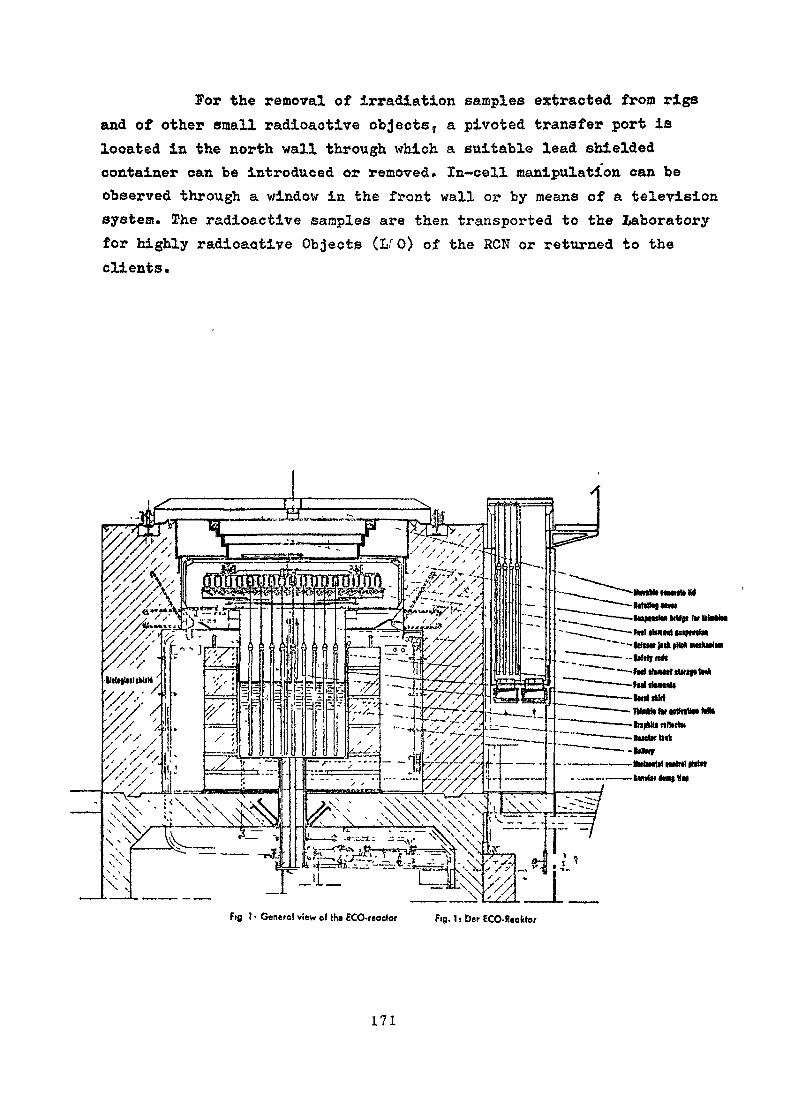
For the removal of Irradiation samples extracted from rigsand of other small radioactive objects, a pivoted transfer port islocated in the north wall through which a suitable lead shieldedcontainer can be introduced or removed. In~cell manipulation can beobserved through a window in the front wall or by means of a televisionsystem. The radioactive samples are then transported to the laboratoryfor highly radioactiye Objects (LrO) of the RON or returned to theclients.
NtlltMMilBlfMIlMfetiw iMa »M nwkwlM
? • Gcnetol view o» Hw ECO-reactor Fig. 1 1 Der ECO-Reoklor
171
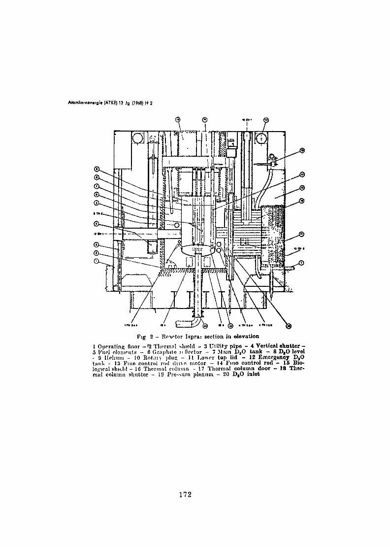
Atomkem»neifli« (ATKE) 13 Jg 0«8) H 2
Fig 2 - Reactor Ispra: section in elevation1 Operating floor -'2 Thermal shield - 3 Ut iMfy pipe - 4 Vertical shutter-5 Fuel cJouinits - 6 Graphito n (Icotor ~ 1 ilajn D,0 tank - 8 DtO level- 9 Holnun - 10 Rot.u> j i luc - 11 Lower top lid - 12 Emergency D,Ot i inV - 13 Fine control ro<! du \« motor - 14 FHJO control rod - 15 Bio-logical shield - 10 Thermal column - 17 Thermal column door - 18 Ther-mal column shutter - 19 Procure plenum - 20 D,O inlet
172
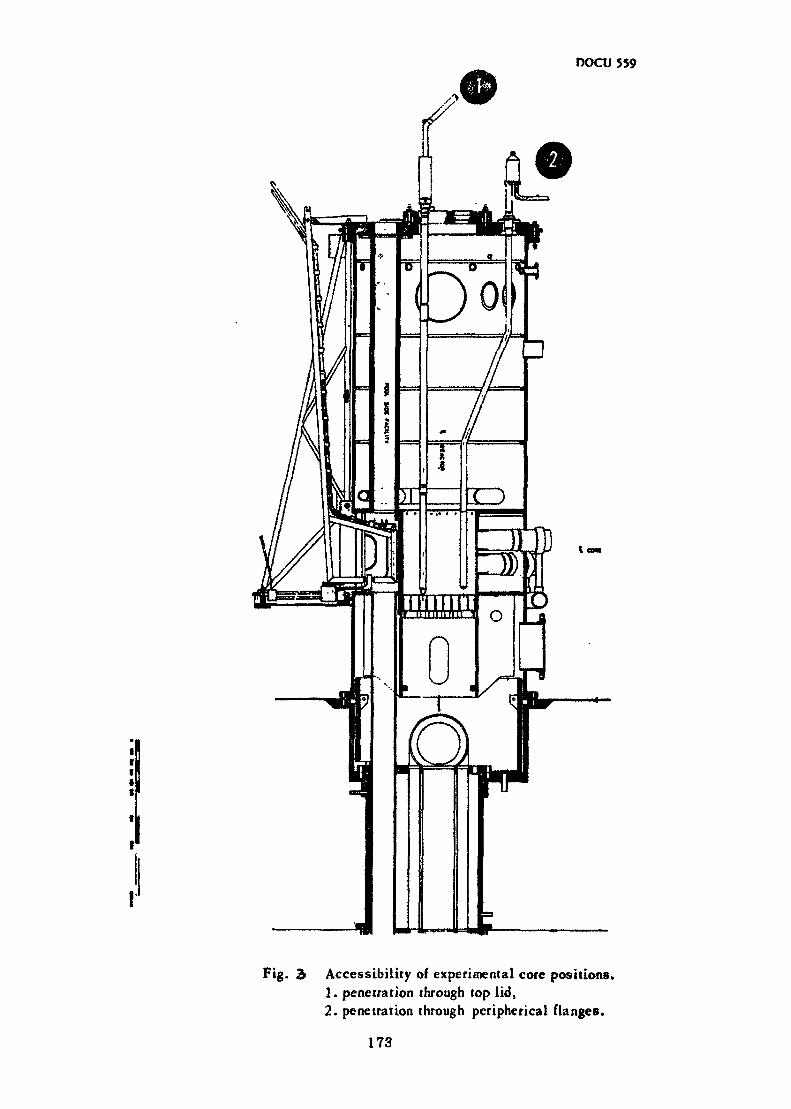
DOCU 559
Fig. 3 Accessibility of experimental core positions.1. penetration through top lid,2. penetration through peripherical flanges.
173
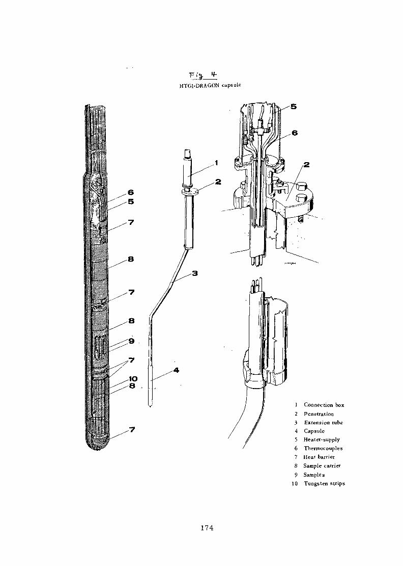
F.'%. f-HTGl-DRAGON capsule
Connection boxPenetrationExtension cubeCapsuleHeater-supplyThermocouplesHeat barrierSample carrierSamplesTungsten strips
174
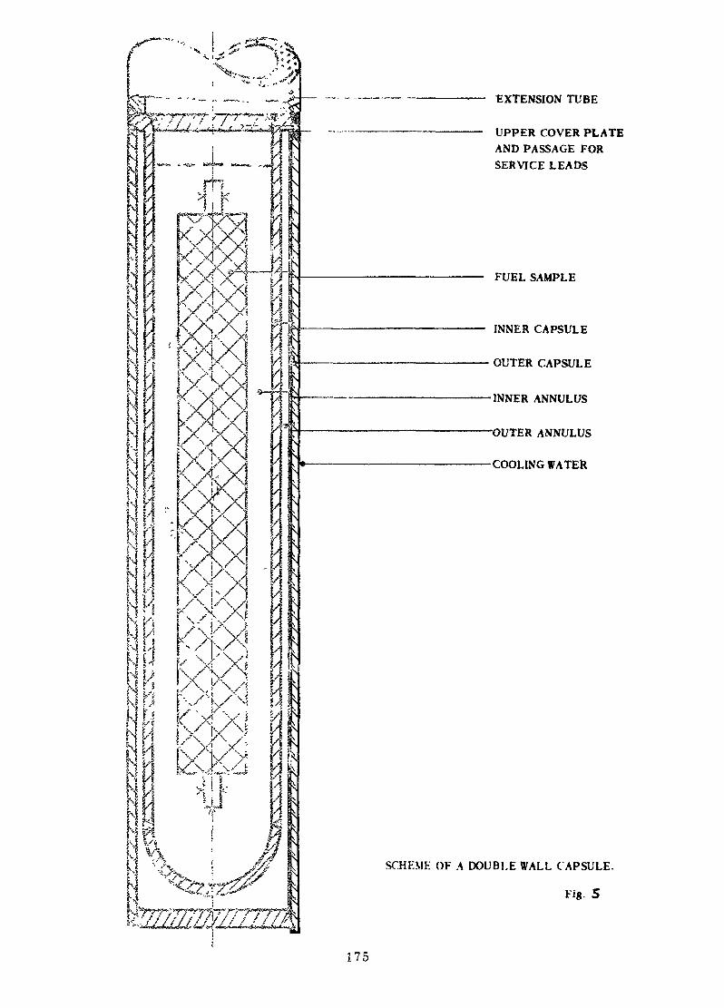
X——'-% . J5 '
*•**«*
EXTENSION TUBE
UPPER COVER PLATEAND PASSAGE FORSERVICE LEADS
' K
kxxFUEL SAMPLE
V
INNER CAPSULE
OUTER CAPSULE
-INNER ANNULUS
-OUTER ANNULUS
-COOLING WATER
•17 7
SCHEME OF A DOUBLE WALL C APSULE.
Fig. S
175
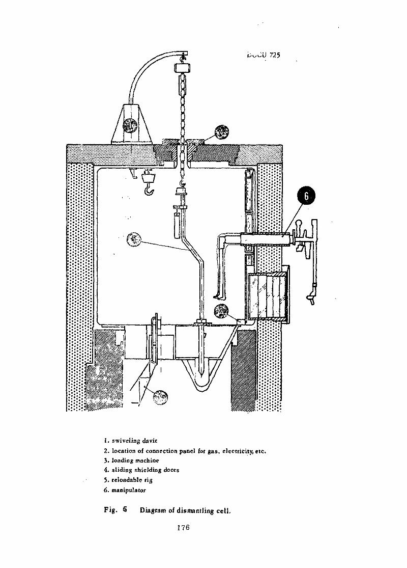
U 725
1. swiveling davit2. location of connection panel for gas, electricity, etc.3. loading machine4. sliding shielding doors5. .reloadable rig6. manipulator
Fig. 6 Diagram of dismantling cell.
176
REFERENCES :
1} First experiments with the zero power facility ECOby W. Hage, H. Hettinger, H. Hohmann, H*J. Metzdorf, P. Toselli, IspraAtomkernenergie (ATKE) 13- Jg. (1968) H.2
2} The. research reactor of the nuclear laboratory at Ispraby S. Barabaschi, A. Bracci, G. Franco, C. Salvettia. Geneva Conf., A/Conf. 15 A/1 #3
3) Irradiation experiments in the HFR and the laboratories of theresearch- establishment of EURATOM and the Reactor Centrum Nederlandat Petfren - A1 survey of possibilitiesby F. Bugl, H. RottgerEUR 3650 e, May 196?
4) fcFR information meeting, December 7th - 8th 19&7 PcttenDocumentation and Library CCR-EURATOM at Petten (Netherlands).
Questions and/or Comments
Could the ECO critical facility be used for reactOT technologystudie? for n+her k4.raR of systems than the ones it has "been originallyconstructed for ? If you change your ^oals, could it still be usedas ? ter,timr facility ?
Well, T *.hink It will be possible, however, new capital invest-irent will te required. Changes in the structure have to be made, thisundertaking requires both tirr.e and a proper detail study from a technicalpoint of view«
"Do you afljree w3 th the spokesman from the ISPRA establishment abouthaving to take up now very seriously non-nuclear activities ?
177

It is our intention to introduce non-nuclear research activitiesin the ISPRA Center and in the other establishment too. Well, at thepresent time, the questjon whether we will he allowed to do this ornot is being studied by the Council of Ministers, ^his Working Group,,is studying the various domains or problems which could be studied atISPRA; we have to consider, e.g. the existing equipment and thelaboratories, whether this equipment is,adequate and also the staff'sexperience. This is really a very complex problem which is beingstudied, we hope to have the solution within the next one or two years.
It is very important to analyse whether this shift, to non-nuclearactivities is reaïly feaseblë. " If we; nov; try to put more effort'innuclear engineering problems, it would be very helpful if it were possibleto show beforehand that there ie-ah alternative way to use this invest-ment if the start does not lead to fcood results in the nucl.ear field.
178
EXPERIENCIAS DE INGENIERÍA CON EL REACTOR JEN-1(ENGINEERING ACTIVITIES IN TEE JEN-1 RESEARCH REACTOR)
byJ. Montes Ponce de LeónJunta de Energía Nuclear
Madrid
Abstrac tss^st^s-srsiK
A brief description of Spain's nuclear programme is given.referring to the-utilization of the JEN-1 reactor in nuclearengineering. Development of the detection system, control andinstrumentation, as well a?, the testing of fuel elements have beenthe active topics within the engineering field.
Personnel training for the nuclear power plants has also beenan important activity. A brief description of the changes made inJEN-1 reactor as well as the reasons which induced such modificationsare ¿jiven.
RESUMEN
En esta comunicación se hace un breve resumen del programa nuclearespañol, indicando la utilización del reactor JEN-1 en el campo de laingeniería nuclear. El desarrollo de sistema de detección, instrumenta-ción y control, junto con la prueba de elementos combustibles han sidolos temas abarcados dentro de este campo. El adiestramiento del personalde las centrales nucleares de potencia ha sido una de las tareas marginales,pero no por eso menos importante. Se da asimismo una idea de la modifica-ción realizada en el reactor y los motivos cpie han inducido a la misma.
INTRODUCCIÓN
Parece conveniente introducir esta comunicación exponiendola situación del programa nuclear español.
/España cuenta en el momento actual con una central Nuclear
de potencia en Zorita, a unos 80 Km de Madrid. Dos centrales nucleares,
179
una de agua hirviendo y otra de grafito gas se encuentran en avanzado es-tado de construcción. Todas estas centrales han sido, construidas bajo ladirección técnica extranjera, aunque gran parte de la obra ha sido sub-contratada con empresas de ingeniería españolas»
El combustible de estas centrales en gran parte es español yse prevee que las próximas cargas de los reactores pueden ser construidasen España. De esta forma se considera que uno de los principales objetivosde la JEN es el desarrollo del ciclo completo del combustible de una centralnuclear.
Con objeto de adquirir experiencia y poner estas técnicas a pun-to se ha realizado el tratamiento del combustible irradiado del reactorJEN-1 y la reelaboración de^nuevos elementos combustibles. Estos elemen-tos ya están entrando en el reactor con resultado satisfactorio. En lasinstalaciones que la JEN posee se trata en estos momentos el combustibledel reactor Saphir.
EXPERIENCIA CON EL REACTOR JEN-1
El reactor JEN-1 (1) se encuentra funcionando desde el año1958. Desde este momento se ha venido dedicando el reactor a cubrir lossiguientes objetivos:
a) Producción de isótoposb) Ensayo de nuevos elementosc) Análisis por activaciónd) Experiencias de Física Nuclear
Dentro del campo de interés de esta reunión merece la penadestacar eKapartado correspondiente al ensayo d ti nuevos elementos rea-lizado en el reactor. Las principales realizaciones han sido:
180
i) Construcción y ensayos de cámaras de fisión e ionizaciónpara el propio reactor y otros reactores experimentalesconstruidos en España (Reactor Argos, Arbi, Coral y JEN-2)
ii) Construcción y ensayos de Equipos electrónicos con destinoa los reactores de investigación anteriormente citados.
iii ) Construcción y puesta en marcha de un circuito experimen-tal para la prueba de placas combustibles del tipo MTR.
A continuación se van a exponer las líneas principales de es-tos ensayos dejando la descripción detallada de los mismos que se puedenver en las referencias correspondientes. Al mismo tiempo se expondránlas consecuencias más importantes que se pueden obtener de los resultadosde estos ensayos con vistas a ulteriores experiencias.
La construcción de cámaras de ionización (2) y de contadoresde fisión (3) ha permitido proveer de detectores a los reactores que sehan construido en España posteriormente, al mismo tiempo que se ha adqui-rido experiencia con este tipo de detectores. Las cámaras construidas nor-malmente se instalan en uno de los canales de irradiación para determinarsus características.
Las experiencias con los equipos electrónicos que componenla instrumentación del reactor, ha hecho posible que junto con la cons-trucción de los equipos mencionados (4) y (5) se prestase una asistenciatécnica, formada por un equipo de especialistas en la puesta en marchade la Central de Zorita. Esta asistencia técnica es interesante no sóloa nivel de técnico superior sino a nivel de técnico intermedio o .ayudan-te. Siempre es factible el adiestramiento de los técnicos superioresen el extranjero, pero generalmente no es posible la formación de losayudantes o auxiliares.
181
La Construcción de^un circuito .experimental para la pruebade elementos combustibles (6) permitió ver..
¡ , , ^,
i) que las técnicas empleadas en un principio en la elabora-ción de estos elementos no eran las adecuadas.
ii) que el reactor tal como estaba construido presentaba seriasdificultades para la realización de este tipo de experimentos.
El circuito esquemáticamente estaba constituido por un prismarectangular donde se podían alojar cinco placas combustibles. Este pris-ma se podía situar en el reticulado del núcleo siendo sus diemnsionesexteriores las de un elemento combustible. En su parte interior se podíaestablecer una circulación de agua descendente a través de las placas com-bustibles y ascendente por el espacio libre de-las mismas. El prisma ter-minaba en dos tuberías, por las que circulaba el agua ascendente y deseen-
'f, /
dente que comunicaba el circuito con un tanque de retención» un cambiadorde calor, y una bomba. De esta forma se podían variar las condiciones derefrigeración de las placas y observar mediante unos termopares adosadosen la misma su comportamiento térmico.
No obstante el resultado negativo de este primer intento,la fabricación de elementos, placa tipo MTR se encuentra perfectamenteestablecida y en el momento actual se tienen elementos combustibles enel reactor JEN-1 fabricados ,en nuestros laboratorios con un grado de' • . . ) <quemado del 107. y con un resultado totalmente satisfactorio. Se hanconstruido elementos de placa circulares y se ha adquirido plena con-fianza en la tecnología de los elementos MTR. Al mismo tiempo se haadquirido experiencia en el tratamiento de elementos combustibles irra-diados, técnicas básicas para poder realizar el ciclo de los elementoscombustibles de las centrales de potencia*
182
CON LAS CENTRALES NUCLEARES
Hasta el taotnento actual la colaboración con las centralesnucleares se puede resumir en dos puntos
a) Formación de personalb) Asistencia a La puesta en marcha»
Se puede decir que la totalidad del personal de grado medioy gran parte del personal de grado superior ha recibido cursos de entre-namiento en el reactor JEN-is On reactor de esta envergadura presenta proble-mas interesantes desde el punco de vista de operación que no aparecen enlos reactores de baja potencia.
Se ha mencionado la asistencia a la puesta en marcha de lacentral. Esta asistencia no sólo se centró en el ajuste y calibradode los equipos electrónicos sino que se extendió a la aproximación a crí-tico y seguridad de la central. Aquí se debe de resaltar no sólo el valorde vun reactor con vistas a una ayuda y colaboración con las centrales sinode un centro con un equipo de expertos capaz de materializar esta ayuda.
MODIFICACIÓN DEL gFACTORAJE??-1
De acuerdo con la experiencia obtenida con el reactor JEN-1en estos años se pueden establecer los siguientes-puntos.
A)El reticulado del núcleo del reactor era pequeño de formaque no se pueden introducir una experiencia en el centrodado que la reactividad consumida en ella no se puede com-pensar con elementos combustibles en la periferia»
b) El desplazamiento del núcleo, en principio realizable a volun-tad pero necesario si se quiere manipular en los canales deirradiación, dificulta la instalación de cualquier circuito.
183
c) Los canales de irradiación y columna térmica no son utilizados, en su totalidad.
d) Es posible aumentar la potencia del reactor a 10 MW sin másque duplicar el circuito de refrigeración primario y secundario.
e) La estructura suspendida, imposibilita la inserción en el núcleode determinado tipo de experiencias.
Por estas razones se ha realizado una modificación del reactorcon objeto de dar mayor flexibilidad a sus dispositivos experimentales y almismo reactor.
Hay que pensar que el reactor JEN-1 fue construido inicialmentesin un programa muy definido de experimentación. Este problema está bas-
itanté generalizado en los reactores, construidos en los paises que se estániiicí anido en la tecnología nuclear* Cuando se tiene experiencia de la ins-talación esr, conveniente-raodificarlo de acuerdo con las necesidades realesdel 'centro donde se encuentran ubicados»
Por estas razones se ha procedido a una modificaciónsustancial del reactor que esencialmente ha consistido en los siguien-tes puntos
a) Sujeción del reticulado del núcleo al suelo
b) Aumento del reticulado del núcleo con la posibilidad decolocar más elementos combustibles dejando la posibilidadde instalar experiencias en el centro del núcleo
j
c) Canales de irradiación abatibles con objeto de poder disponerde una zona de irradiación en las tres caras del reactor.
Todas estas modificaciones dejan al reactor preparadopara una segunda etapa en que se aumentará la potencia del reactor»
184
CONCLUSIONES
De acuerdo con esta modesta experiencia cabe señalar lassiguientes conclusiones
a) Un reactor experimental de cualquier tipo que sea puedetener un papel muy importante en la formación de técnicoscon destino. Esto es aún más importante para los paisesque en un futuro inmediato van a instalar centrales de po-tencia. El primer contingente de técnicos es convenienteque inicie su formación en un reactor. Posteriormente estostécnicos completan su formación en el extranjero. Los técni-cos medios o auxiliares, necesariamente tendrán que iniciary completar su formación con el reactor experimental.El manejo de distintos detectores, la medida de potencia» ladeterminación de flujos neutrónicos, la operación de un reac-tor, son técnicas que sólo se pueden aprender con un reactor ex-perimental.
b) Si el país intenta nacionalizar al máximo los combustiblesnucleares, necesariamente ha de realizar pruebas con los mismos.Estas pruebas pueden abarcar desde medidas de reactividad y distribución neutrónica que puede hacerse con reactor de cualquier ti-po hasta pruebas de comportamiento neutrónico. Con reactores
de flujo superior a 101-*-?—TSTT——r~ se puede realizar pruebas que(cmZ)(seg)menos den información sobre el comportamiento del combustibleen um primera fase. Es de notar que«los fallos de los ele-mentos combustibles generalmente aparecen encías primeras fa-ses de la irradiación. Si se quiere observar las alteracionespor irradiación hay que recurrir a un reactor de flujo y ahípuede surgir un punto de colaboración internacional.
185
c) Si el país no intenta nacionalizar la fabricación de com-bustible no tiene,porque acudir a reactor de alto flujo. Nohay necesidad de ponstruir circuitos de irradiación.
d) En cualquier caso, aún cuando los reactores seaa adquiridosllave en mano, es indudable que estos reactores, más tardeo más temprano experimentarán fallos en su instrumentacióno en su comportamiento nuclear. Ante estos fallos es precisoque exista un equipo de expertos bien preparado en torno deun reactor. Si este no existe necesariamente se tendrá quedepender de la casa suministradora con las dificultades queesto representa en coste y tiempo. Dado que el reactor de.una central es menos accesible que un reactor de investigaciónlos técnicos encargados de aquél, si bien conocer mejor sufuncionamiento como conjunto, han tenido menos ocasiones o acaso ftífcguna de experimentar y de efectuar ensayos con él, enuna palabra generalmente conocen menos el comportamiento normalde los componentes del reactor.
e) En un reactor experimental se pueden tratar de ensayarnuevas disposiciones con métodos de análisis que son lúe-
¡ /go aplicables al reactor o reactores que ocupan la central.
186
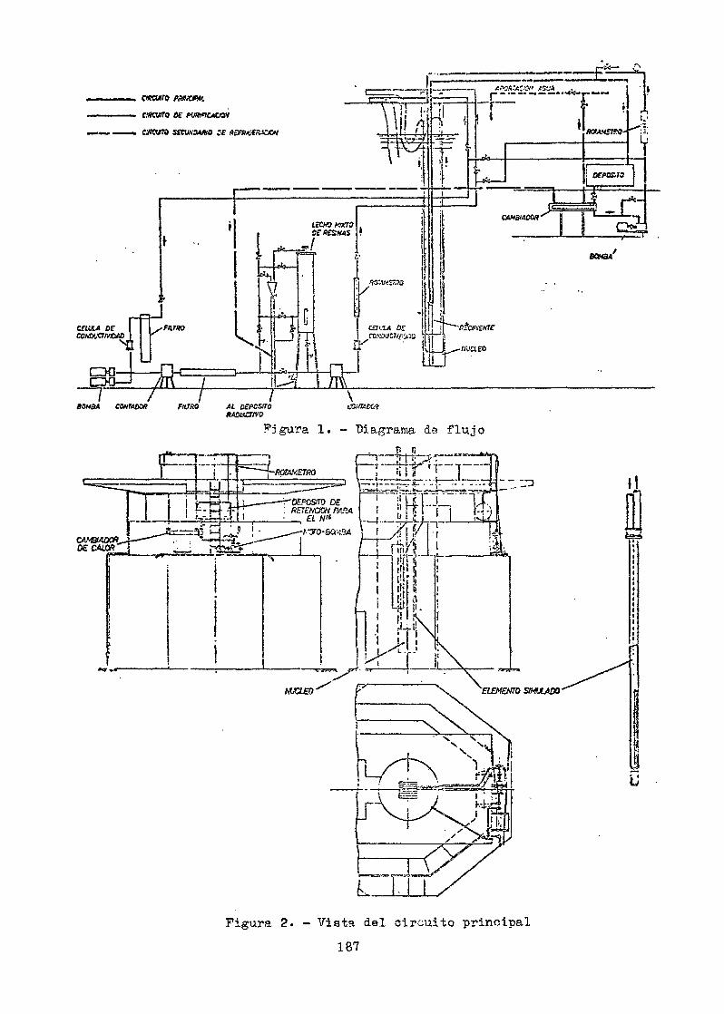
C.fKVíTQ K PUfKnCWCH
cuatro SECU.MWHO ;•£
£:p_
c —
GWSWOtlff
i isPrSr1
]u
D£f OS-JO
LJÍc¿Ü
«wa»
BOH3A CONTADO* FUTRO AL DZPCSI70RAUlKStVQ
\figura 1. - Biagraiiaa de flujo
"Ttíh r1"¡M'f 'i—"T"
I ; , , ti * t___ L i
Figura 2* - Vista del circuito principal187
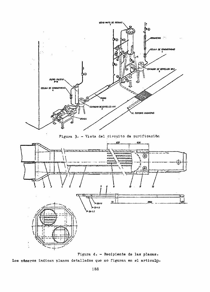
IKWMHTOCf «ESSMSV
( I yOTíGtX Oí CMMCTMM0
i .x
•At DOVSOO MOUCtHO
Figura 3» - Vista del circuito de purificación3f_
Í
rr-f}!"" - g
1 3 9 a ir n
-4 ——— r*| ————————————— . ——————— T_]
\ \ ^A.c« .r • - ! 3000 !t»
P-SS-T-3
Figura 4. - Recipiente de las placas.Los níimeros indican planos detallados que no figuran en el articul^j.
188
REFERENCIAS
(1) Descripción general del Reactor JEN-1. Enriquez de SalamancaM., JEN 97 DF/I-30
(2) Estudio y diseño de cámaras de ionización compensadas.Artacho E, et al. Anales Real Soc. Españ. Fis. y Quim _1, 1963
(3) Diseño y construcción de cámaras de fisión miniatura.Artacho, E., Rufián, E., Montes,'\J. Anales Real Soc. Españ.Fis. Quim. 59-A, 1963
(4) Reactor ARBI. Tanarro A, et al. Publicación de la JEN
(5) Reactor JEN-2: Montes, J. Martín Ñuño, C., Fajardo, M.Energía Nuclear, 51, 1968
(6) Circuito.de prueba de elementos combustibles.Maroto, J. Artacho, E.,Montes J. Energía Nuclear, 7, 28, 1963
Questions and/or Comments
It has beer, mentioned that there are plans to produce nuclearfuel in Spain for all fuel cycles (keeping in mind that there are atleast two types of reactors i.e. gas-cooled ACT? and PWR) . Actually,what fuel elements do you intend to produce ? Or do you plan to produceboth types ?
The first fuel load will come from abroad, but we clan to producethe second logins;. Regarding? the graphite-gas-natural uranium reactorin Spain, we have experience with natural uranium and we do not anticipategreat problems for the production of these fuel elements; on the otherhand, there is considerable interest from industry regarding the fuelfabrication. We t>lan to form n nuclear fuel elementmanufacturingcompany, which will be partly financed from an official institutionfor the development of industry and the rest would be private capital,mostly from the electricity utilities.
189

Spain is an example of a European country establishing rather fastnuclear power reactors without having had time for its research reactorsto cope"~wiith the problems in nuclear power reactors. Bo you feel nowthat it woxild have been easier for the electric power companies tooperate these nuclear power reactors if you have had enough time to domore elaborate work with your research reactors in designing loops orcertain types of experimen-ts ? - . ; . , • ' - ,-,
I believe that for a country like Spain, a country of our industriallevel, it is not possible to build á nucí ear'power' plant completely onour own'." Therefore, it is necessary1'that this- nuclear power plant bebuilt under a contract with some foreign firm. However, T believe theexperience with a research reactor is very useful, firstly in order to+ rain personnel, and secondly in order to acquire experience with regardto the component parts of these nuclear installations, such as theelectronic equipment, the fuel elements, and so forth. T believe, weare tnlkiig about two different subjects . The" existing gap betweenresearch and power reactors design has already been mentioned to-dayand in Spain we also have to make this distinction.
I am amszed that with" the research programme you are Hackingbehind,1" the progress you hsve made in your power reactors, and sinceit seems to work well, I should lake to ask the panel to investigatethe question whether small countries really have to go - before theystart with their power reactor programme - into elaborate experimentsin order to be well equipped and prepared for the power reactors.
I believe that the question being put is to what extent moresophisticated experience is required to ever become a good reactormanufacturer customer ? ind this Isa question which we could possiblyexplore in one of the panel sessions. T think there TP n v/en"'th ofexperience in this psnel at various levels approaching this sort ofsatisfaction and opinions will vary. We have heard almost dogmaticrequirements for elevated research facilities in order to even beconcrete customers and we have heard that it is possible to go withforeign assistance into at least manufacturing, and I should like toleave the subject for a thorough and proper discussion for the workingsessi on.
190
PROGRAMS DE INGENIERÍA EN LOS REACTORES ARGENTINOS(ENGINEERING PROGRAMMES IN THE ARGENTINIAN REACTORS)
J. Cosentíno et al .Comisión Nacional de Energía At&rnica,Buenos Airea, Argentina
Abstract
This paper is a general review of the engineering activitiescarried out in Argentina in connection with the ArgentineNuclear Reactors. The present national participation in theAtucha Nuclear Power Plant Project is particularly mentiond.
Resumen; En la presente memoria se pasa revista a lostrabajos realizados en la Argentina en los temas ana-lizados por esté Grupo de expertos. En particular semenciona la etapa presente de participación en el pro-yecto de la Central Nuclear Atucha.
PROGRAMAS DE INGENIERÍA EN LOS REACTORES ARGENTINOS
La Comisión Nacional de Energía Atómica (CNEA.) inició en 1954 un programade trabajo en ingeniería nuclear. En lo referente a reactores nucleares lasrealizaciones que han orientado el trabajo en ingeniería han sido las siguien-tes!a) Enero de 1958. Alcanza criticidad el RA1, primer reactor construido en la
Argentina. Potencia térmica 5 kW.b) Mayo de 1960. Alcanza criticidad el RAO, reactor de potencia nula destina-
do al estudio de modificaciones a introducir al RA1.c) Mediados de 1961. Se realiza una modificación de RA1 que alcanza la confi-
guración nuclear, el tipo de elementos combustibles, el tipo de barras decontrol, el equipo electrónico, etc. Potencia 150 KW.
d) Mediados de 1966. Alcanza criticidad el RA2, segundo reactor de potencianula destinado al estudio del RA3«
191
e) Mayo de 19&7« Alcanza criticidad el RA3? reactor que opera durante el pri-mer año y medio a 2,5 MW y que actualmente opera a 4 MW. Flujo térmico eni -3 pcajas de irradiación de 2 a 6 x 10 n/cmssegún ubicación.
f) Marzo de 197Q- Se inicia un proyecto de aumento de potencia del RA3 delorden de 10 - 12 MW.Como resultado de la decisión de construir los reactores mencionados, in-
cluyendo su carga de elementos combustibles en el país, fue necesario comenzarmuy temprano un programa de investigación y desarrollo en problemas de ingenie-ría.
Se citan a continuación las tareas realizadas y programas .referentes a:i) Elementos combustibles y materiales.ii) Transferencia del calor y fluidodinámica.iii) Instrumentación.iv) Química de reactores.
i) Elementos combustiblesEn este sector, paralelamente a un trabajo de investigación y desarrollo
de apoyo, se han elaborado las siguientes Cargas de elementos combustibles:a) Primera carga del- RA1. Elementos combustibles UO /Al tipo placas.b) Segunda carga del RA1. Elementos combustibles UOp-C/Al cilindricos.c) Primera y segunda carga del RA3« Elementos combustibles U-A1/A1 tipo MTR.d) Fabricación de las cargas para el RAO y RA2.e) Desarrollo de elementos reflectores de U0? natural/Al para el RA3 y RA2.f) Desarrollo de elementos combustibles U0?/Zr para el RALg) Desarrollo de un prototipo de elementos combustibles tipo MZFR.
Estas operaciones han exigido pruebas en reactores de distintos prototi-pos. Pueden citarse los siguientes trabajos:
Ensayo en el RA1 original de un prototipo UOp-C/Al.- Verificación de la potencia máxima que puede obtenerse por elementos com-
bustibles tipo RA1 en un circuito del RA3.- Determinación de quemado en el RA3 de elementos combustibles tipo U0?/Zr
mediante la elaboración de una caja MTR especial donde se han sustituidochapas U-A1/A1 por cuatro elementos cilindricos en consideración.
192
Irradiación en el RA3 de un prototipo de reflectores de U0? natural/Al- Irradiación de muestras metálicas en el RA1 en un circuito de baja tempe-
ratura (N? líquido).- Irradiación de muestras metálicas a partir del próximo año en el HA3 en un
circuito de "baja temperatura (N_ líquido).¿ de
- Irradiación en el extranjero de muPstras/UO,., nacional sinterizado compara-tivamente con muestras de U0_ extranjero. Instalación en el RA3 (aproxi-madamente año 1971) de un sistema de irradiación de cápsulas combustiblestipo cyrano y policarpo (refrigerado NaK).Programa de utilización de la celda caliente superior del RA3 para desman-telado e inspección de combustible MTR irradiado y medición por contajegamma de distribución de quemado.Programa de irradiación y observación post irradiación de un prototipo tipoMTR en el extranjero.
En relación con estas tareas realizadas en el campo de elementos combus-tibles, se ha proyectado, construido y operado una planta piloto de reelabo-ración de elementos combustibles tipo RA1. Actualmente dicha planta pilotose encuentra en proceso de modificación para adaptarla a la reelaboración deelementos combustibles RA3 y blanket uranio natural RA3.
En cuanto a ensayos de materiales estructurales y de blindaje se ha efec-tuado poco trabajo de investigación sistemático dado que en general se han uti-lizado materiales suficientemente conocidos. Podría citarse sin embargo un tra-bajo realizado con el propósito de determinar el tipo de hormigón pesado quemejor se adaptaba, a las posibilidades ael país y las exigencias del RA3»
En lo referente a ensayos no destructivos, se realiza tanto la' inspecciónde las partes de los elementos combustibles como del elemento terminado (ultra-sonido, corrientes parásitas, rayos X, espectrometría de helio).
ü) Transferencia del calor y fluidodinátnicaLas actividades mencionadas han exigido a este grupo trabajos de ingeniería
de diseño, ensayos d) sistemas, determinación de confiabilidad de componentesy circuitos. Pueden mencionarse las siguientes tareas:- Estudio en el RA1 de una versión modificada de la distribución del refrige-
rante.
193
- Estudio técnico experimental de las características de refrigeración de unaversión intermedia del RA1 con refrigeración forzada descendente.
- Ensayo en un modelo hidráulico del sistema de entrada de agua de refrigera-ción en el RA3«
- Ensayo en el RA3 de un sistema de colchón caliente.- Estudio en un modelo y posteriormente en el reactor de distintas soluciones
para el sistema de compuertas en el cono de aspiración del núcleo.- Estudio teórico de la evolución del caudal de refrigeración después de la
detención de las "bombas. Estudio de la eficiencia de un volante de iner-cia. Actualmente se encuentra en construcción un volante para las bombasde refrigeración. Se ha programado un trabajo de verificación experimentaly regulación de compuertas.
- Ensayos de un "blanket" de uranio natural instrumentado en el RA3» Determi-nación de las condiciones de refrigeración.
- Cálculo teórico de un blindaje gamma para la columna térmica del RA3.Predicción de la temperatura de equilibrio del grafito. Verificación ex-perimental de las- mismas.
- Cálculo del blindaje térmico para el hormigón de blindaje del RA3» La me-dición experimental se efectuará a potencias superiores de operación delRA3.
- Construcción de una caja de elementos combustibles tipo MTR instrumentadapara determinar temperatura en regímenes estacionarios y transitorios.
- Aspectos termohidráulicos del circuito para ensayos de elementos del RA1 enel RA3.
- Determinación de absorción gamma por métodos calorimétricos en distintasposiciones del núcleo del RA3- Este trabajo tiene relación con el consumode N_ en el circuito del RA3»
- Proyecto general de los sistemas principales y auxiliares de refrigeracióndel RA1 y RA3.
- Análisis de los distintos circuitos desde un punto de vista de confiabili-dad y ensayo experimental de distintas circunstancias.
- En loop' de laboratorio se han analizado distintas secciones de ensayos es-tudiándose los fenómenos básicos de "burn-out".
194
iü) Instrumentación y controlLos sectores respectivos han desarrollado y construido prácticamente la
totalidad de los equipos utilizados en nuestros reactores. Posteriormente ala puesta en servicio de los reactores, este grupo realiza una tarea de super-visión y control de los equipos a fin de mejorar sus características. Estemétodo ha permitido introducir mejoras en la conflabilidad de los sistemas.Pueden citarse las siguientes mejoras:- Puente de alta tensión estabilizada para contador proporcional.- Amplificador lineal de pulsos de alta ganancia.- Discriminadores y conformadores,- Circuitos de contaje a tiempo o a contaje predeterminado.- Integradores lineales y logarítmicos de cuatro décadas con medidor de pe-
ríodo.
- Puente de alimentación para cámaras de ionización compensadas o no.- Amplificadores .de corriente de cámara lineales y logarítmicos de siete
décadas con medidor de período.- Disparos de seguridad con nivel ajustable, histéresis y reposición manual
o automática.- Sistemas lógicos de enclavamiento y seguridad transistorizados.- Sistema de señalización y alarma de fallas.- Monitores de área para radiación gamma a estaciones múltiples.- Monitores de área portátiles.
- Espectrómetros monocanales para centelleadores usados como monitores deproducto de fisión en agua y en filtros de aire.
- Sistemas de control automático de barras de regulación de reactores.- Sistema de posicionado automático de muestras o detectores.- Se trabaja actualmente en la calibración de un monitor de potencia por N..,.- Se trabaja en la actualidad en la calibración de un monitor de potencia
térmica.- Se ha iniciado un programa de trabajo con asistencia del OIEA en técnicas
digitales en instrumentación de reactores (adquisición de datos por cana-
195
les múltiples, su elaboración y posterior empleo en operaciones de controlincluyendo uso de computadoras en línea y proceso).
- Se fabrican en el país las cámaras de ionización que se utilizan en nues-tros reactores.
- Se han desarrollado distintos sistemas de barras de control y regulación.
iv) Química de reactoresEn este campo se ha trabajado también en relación con los proyectos de
nuestros reactores. Asimismo se ha trabajado en algunos campos (corrosión,por ej.), pero sin hacer uso intensivo del reactor como herramienta experimen-tal. Pueden citarse las siguientes tareas:- Estudio en el RA1 del efecto grafito-aluminio. Se ensayaron varios tipos
de pintura epoxi. Se ensayaron los resultados luego de diferentes tiemposde irradiación.
- Se analizaron distintas técnicas de pasivación de Al.- Se encaró un accidente importante del RA3 ocurrido por un fallo en los cir-
cuitos de purificación del agua.- Se diseñaron los circuitos de demineralización continua. Se proyectaron
sistemas de manejo de las resinas irradiadas.- En el autoclave se han ensayado muestras de Zr y Al en distintas condi-
ciones de trabajo.- Trabajos de análisis por activación de distintos materiales.
PARTICIPACIÓN DE LA CNEA EN EL PROYECTC ATOCHA
Ya en 1965 al iniciarse el estudio de la factibilidad de instalación deuna central nuclear en la Argentina, diferentes grupos de la CNEA, entre losque se contaban aquellos relacionados con los problemas de ingeniería en con-sideración, fueron llamados a participar en las diferentes etapas del estu-dio que culminó con la decisión tomada en febrero de 1968 de adquirir unacentral nuclear de 319 MW(e) del tipo de agua pesada a presión.
La circunstancia de contarse con personal con experiencia suficiente enaspectos de tecnología nuclear permitió encaminar el estudio en forma inde-pendiente.
196
Comenzada la etapa de proyecto y construcción por parte de la firma pro-veedora la CNEA delegó personal con el propósito de participar estrechamenteen diversos temas. En lo que sigue sólo se mencionan aquellos que fueron in-tegrados con personal formado en alguna de las cuatro disciplinas analizadaspor este Grupo de expertos. Se resumen brevemente las principales líneas detrabajo encaradas.
Diseño de elementos combustibles? pueden considerarse dos campos de ac-tividades principales.a) Determinación de distintos modelos da cálculo de las barras de elementos
combustibles.b) Diseño del elemento combustible, programa de fabricación, ensayos de ca-
racterísticas estructurales en un circuito.Materiales y procesos de fabricación de grandes componentes. Se ha par-
ticipado en todas las etapas de construcción de los grandes componentes (re-cipiente de presión, generadores de vapor, etc.).
Sistemas de inspección en servicio. Se participa en el proyecto del sis-tema de ultrasonido previsto para el sistema a presión.
Aspectos termodinámicos de los canales de refrigeración. Se han analiza-do teóricamente las condiciones de trabajo correspondientes a distintas confi-guraciones de elementos combustibles. Se participará en los ensayos a reali-zarse próximamente en un circuito. Se verificaron in situ las condiciones fi-nales.
Aspectos termohidráulicos de los circuitos principales y auxiliares delreactor. Se ha participado en al estudio teórico de optimización de parámetros,determinación de las condiciones de trabajo para distintas potencias de servi-cio, condiciones de arranque y parada. Se participará en las pruebas de com-portamiento y verificación de condiciones de trabajo.
Sistemas de instrumentación de la Central. Se ha participado en la formu-lación de los esquemas de regulación de la Central, particularmente en la ali-mentación de vapor a la turbina y los circuitos del moderador.
Sistemas de tratamiento de agua pesada y ligera. Se participa en el aná-lisis de los distintos sistemas de purificación, desgasificación, reconcentra-ción, reeombinación, sistemas de eliminación de desechos radiactivos, gaseosos,líquidos, sólidos.
197
Sistemas de control de proceso químico de la planta. Instalación de labo-ratorios, equipos, técnicas de medición, etc.
Seguridad nuclear de la instalación. En este tema participa la casi tota-lidad del personal mencionado en los puntos anteriores. Se analizan las condi-ciones de diseño enfocándolas desde el punto de vista de seguridad. Se consi-dera la conflabilidad de los sistemas de emergencia, etc.
Participación de la industria nacional en el proyecto. Pue decisión de laCNEA asegurar la máxima participación posible de la industria nacional en elproyecto. En ese sentido se emprendió una activa acción de esclarecimiento yestímulo a fin de compenetrar a los empresarios con los requerimientos de latecnología involucrada. Aproximadamente setenta órdenes de compra de compo-nentes electromecánicos fueron hechas en el país. Una elevada proporción deellas están vinculadas a los temas de participación mencionados (precalenta-dores del agua de alimentación; condensadores principales; intercambiadoresde calor de los circuitos intermedios de refrigeración; recipientes de procesode material austenítico y ferrítico; bombas de movimiento de líquidos activos?válvulas y cañerías; sistemas de ventilación activos; sistemas de purificacióny tratamiento de agua; sistemas de filtro de eliminación de desechos radiac-tivos, etc.). La posibilidad de contar con personal capacitado en los temaseji cuestión ha permitido resolver situaciones que en caso contrario habríanpodido disminuir el grado de participación de nuestra industria.
Para hacer frente a las necesidades del proyecto se inició la formacióndel personal de operación sobre la base de profesionales provenientes de cen-trales convencionales. Personal de la CNEA formado en los temas de análisisparticipa actualmente en el programa de formación de este personal. Asimismoalgunos de ellos han sido seleccionados para formar parte del personal deoperación de la Central, mientras que otros participarán en las etapas inicia-les de puesta en servicio de la misma.
ConclusionesEl programa de trabajo encarado por la CWEA en cuanto a problemas de
ingeniería, permitió concretar una serie de realizaciones en el campo de losreactores de investigación y preparar una infraestructura técnico-científicaque posibilita aspirar a participar en el proyecto de la primera central nu-clear en construcción en la Argentina. La experiencia demostró que los re-querimientos de personal de esta obra han superado las disponibilidades, por
198

lo cual ha sido necesario intensificar la formación de personal en los temasque se analizan. Los temas encarados en el programa original han demostradocubrir los aspectos más importantes que se presentan en esta etapa del pro-yecto. Las instalaciones han resultado ser razonablemente suficientes paraesta etapa del programa nacional, pero seguramente deberán sufrir un importanteaumento si se aspira a lograr una creciente participación de la tecnologíanacional en nuevos proyectos. Las relaciones ya iniciadas con la industrianacional, con ocasión de la construcción de nuestros reactores de investiga-ción, han sido una buena base para lograr su activa participación en el pro-yecto Atucha, pero no hay duda que queda todavía una importante tarea porrealizar, como lo han demostrado los puntos importantes relativos a la inge-niería tratados en esta reunión.
199
SOME EXAMPLES OF RESEARCH REACTOR UTILIZATION,COSTS AND TRENDS IN THE U.S.
Notes for the IAEA Panel onEngineering Programs in Research Reactors,
Vienna, Austria,27 - 31 July 1970
Prepared by David H. LennoxArgonne National LaboratoryArgonne, Illinois, U. S. A.
ABSTRACT
New research reactor facilities in the U. S. are reviewedbriefly; typical engineering development problems, with emphasison the LMFBR/ are listed. Examples of the utilization of varioustypes of research reactors are given, and engineering experimentssuitable for low power reactors are tabulated. Costs associatedwith selected reactors and typical experiments are listed toprovide some perspective for potential reactor customers and ex-perimenters. Thoughts about schemes for cost reduction areincluded.
INTRODUCTION
The purpose of these notes is to provide some typical information on costsand possible engineering experiments to help define reasonable goals for the utiliza-tion of research reactors. This is not inte aded to be a complete catalog of experi-ments or an exhaustive survey of U. S. research facilities. Instead, material isselected to illustrate the range of resources required for research with differentreactor types and powers.
BRIEF REVIEW OF THE STATUS OF TEST,RESEARCH, AND UNIVERSITY REACTORS
For background, a statistical summary of U, S. reactors is as follows:
Total operable - 114Under construction - 5Planned - 3Shutdown or dismantled - 27
201
Some of the recent highlights include:
a) The Advanced Test Reactor (ATR) started operation as anirradiation test facility at 250 MW in December 1969.Within in-core pressurized water loops, stainless steelsamples are being irradiated and corrosion tests run onzirconium alloys as a function of oxygen concentration.
b) The Materials Test Reactor (MTR), which started operationin 1952 and was the first U. S. reactor built specifically forirradiation and testing, discontinued these services inJune 1969.
c) The Southwest Experimental Fast Oxide Reactor (SEFOR)achieved criticality in May 1969, and a license wasissued for pulsed and full power operation in January'1970. SEFOR is a 20 MW, sodium-cooled fast reactordesigned to investigate the Doppler effect in PuO0-UO9
X ^ «
fast systems and the negative power coefficient undertransient conditions.
CHARACTERISTICS OF REACTORS PLANNEDOR UNDER CONSTRUCTION
a) The Fast Flux Test Facility (FFTF) will provide a fast-neutron flux for testing, instrumented fuels and materials in flowing sodium up to, and including,failure. Criticalltyr is scheduled for 1974. Some of the major experimentalfeatures of FFTF are:
Reactor Power: 400 MWReactor Coolant Outlet Temperature: 860-1050°FCore Arrangement: , 91 lattice positions
with 75 driver-fuelsubassemblies
Subassembly Length: 3 ft fuel, 4 ft maxgas plenum
Fuel Composition: 20-30 vol % PuO, ,70-80 vol %
202
Number of Instrumented In-core TestPositions 3-9
Closed Loops1) Initial, Number:
General Purpose (2 MW) 2Special Purpose 2 (User Supplied)
2) Ultimate NumberGeneral Purpose (4 MW) 4
3) Maximum Loop OutletTemperature 1400 CF
Peak Flux (nv)1) Initial 7xio1 5
2) Advanced Cores 1.3xl016
b) The Loss of Fluid Test Facility (LOFT) is a 55-MW reactor facility forintegral safety tests related to loss-of-coolant accidents in water power
t
reactors. Problems associated with the effects of blowdown and emergency; / >coolant injection will be studied. Progress continues on the design andconstruction, with operation scheduled for 1973.
c) The Power Burst Facility (PBF) is a pulse-type, oxide-fueled, experimentalwater-moderated reactor under construction at the National Reactor TestStation (NRTS) and scheduled to start experiments in. 1971. Major objectivesof the test program center on the investigation of mechanisms of fuel-rodfailure, and their thresholds and consequences. Test variables includefuel-pin spacing and size of test cluster. Power transients to 20 MW areplanned.
d) Research and Teaching Reactors are scheduled for the following institutions:
Columbia University Triga Mk II (250 kW)North Carolina State Pulstar (1 MW)Colorado State Triga Mk 111(1 MW)New York University Triga Mk I (250 kW)New York Hall of Science Triga Mk II (250 kW)
RESEARCH AND DEVELOPMENT PROGRAMS
To provide the perspective needed to understand the trends in research and testreactor utilization in the U. S., it is worthwhile to review briefly some objectives of ourdevelopment programs.
203
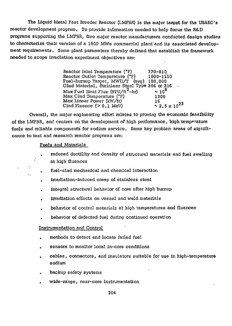
The Liquid Metal Fast Breeder Reactor (LMFfiR) is the major target'for the USAEC'sreactor development program. To provide information needed to heïp focus the R&Dprograms supporting the LMFBR, five major reactor manufacturers conducted design studiesto characterize their version of a 1000 MWe commercial plant'and its associated develop-ment requirements. Some plant parameters thereby defined that establish the frameworkneeded to scope irradiation experiment objectives are:
Reactor Inlet Temperature (°F) 770-810rReactor Outlet Temperature (°F) 1000-11^50Fuel-burnup Target, MWD/T (avg) 100,000Clad Material, Stainless Steel Type 304 or ,316 , -Max Fuel Heat Flux (BTU/ft2-hr) •»• 10°Max Clad Temperature (°F) 1300Max Linear Power (kW/ft) 16Clad Fluence (> 0.1 MeV) *• 2.5 x 10
Overall, the major engineering effort relates to proving the economic feasibilityof the LMFBR, and centers on the development of high performance, Mgh temperaturefuels and reliable components for sodium service. Some key problem areas of signifi-cance to test and research reactor programs are:
Fuels and Materials
reduced ductility and density of structural materials and fuel swellingat high'fLuences
, fuel-clad mechanical and chemical interaction
» irradiation~induced creep of stainless steel
integral structural behavior of core after high burnup
. irradiation effects on vessel and weld materials
behavior of control materials at high temperatures and fluences
. behavior of defected fuel during continued operation
Instrumentation._and ControlI
. methods to detect and locate failed fuel
sensors to monitor local in-core conditions
cables, connectors, and insulators suitable for use in high-temperaturesodium
backup safety systems
wide-range, near-core instrumentation
204
methods to accommodate swelling of core components and irradiation-induced creep
Sodium Technology
the effect of flow and hoat transfer on corrosion and mass transfer
methods to cope with fission products in the primary sodium
on-line instruments for measurement of sodium quality
effects of sodium on the mechanical properties of materials
Safety
fuel-element failure mechanisms and thresholds
propagation of local fuel failure
fuel-coolant thermal interactions resulting from power-flow mismatch
Heal: Transfer
effect of radiation on sodium superheat
Some problem areas that require in-pile research for reactors other tnan the,MFBR include:
corrosion and hydriding of Zircaloy fuel clad at high temperatures
effects of fuel-pin spacers on heat transfer
uncertainties in critical heat flux in water-cooled reactors
fission product release from graphite fuel and subsequent transportand deposition
the effects of the reactor environment on the materials properties ofprestressed concrete reactor vessels
IRRADIATION FACILITIES IN USE FORFAST REACTOR DEVELOPMENT
EBR-II, the only AEC fast test facility, is currently operating at 50 MW (performanceit 62.5 MW was verified in September 1969). An instrumented subassembly has operatedsuccessfully and instrument facilities are planned for: a) out-6f-core tests at fast fluxes
205
to 1010 and temperatures to 1200°F; b) in-core at fast fluxes to 1015 and temperaturesfrom 950 to 1400CF.
At the beginning of a recent run there were 38 experimental subassemblies inthe reactor, with about a total of 700 experimental fuel pins and capsules containingcladding, control, and insulator materials.
Several thermal reactors provide irradiation data of value to the fast reactorfuels and materials program. For example, General Electric Test Reactor (GETR) isused in studies of the behavior of defected, mixed-oxide fuel, and TREAT for theoverpower transient testing to destruction of fuels in flowing sodium. For the future,investigations of fuel-element-failure propagation in sodium package loops are plannedusing ETR as the driver with a thermal-neutron filter to adjust the spectrum.
PROBLEMS WITH FAST REACTOREXPERIMENTS IN CURRENT FACILITIES
In Thermal Reactors
For fuel-pin tests, proper fission densities can be obtained, but the resulting•adial power distribution is atypical of fast reactor conditions and the clad fast fluences too low. Likewise, pin bundles suffer from flux de près s ion, and the use of neutronalters to harden the spectrum leads to inefficiencies because of the large driver reactor>ower requirements for a given power density in the test section.
In EBR-II
In ordfir to dupJ.foc't'? the p<?o.k heat rates anticipated in large fast resctors (16 kW/ft),dghly enriched uranium is usually added to mixed-oxide fuel pins before testing in EBR-II.Consequently, in experiments with such pins the ratio of clad fluence to burnup is lower>y a factor of about three than anticipated for the target plant. This disparity is mitigatedsomewhat because the harder spectrum in the metal-fueled EBR-II (in comparison witharger oxide systems) enhances the damage effect.
REACTOR OPERATIONAL ANDEXPERIMENTAL COSTS
Costs given for reactor operation and experiments at one research center can-ict be used directly to predict what they might be at another location because of thenyriad of differences in such things as accounting procedures, charges for support
206
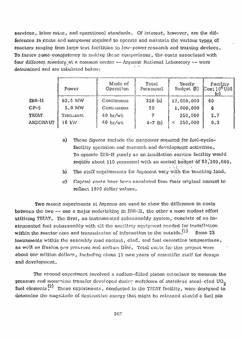
services, labor rates, and operational standards. Of interest, however, are the dif-ferences -in cpsts and manpower required to operate and maintain the various typ^s, ofreactors ranging from large test facilities to low-power research and training devices.To insure s Qsrçç--consistency in making these comparisons, the costs associated withfour different reactors at a common center — Argonno National Laboratory — were71 'determined and are tabulated below:
EBR-IICP-5TREATARGONAUT
PowerMode of
Operation
ContinuousContinuous40 hr/wk40 hr/wk
TotalPersonnel
328 (a)50
74-7 (b)
YearlyBudget ($)
12,000,0001,000,000
250,000< 250,000
FacilityCostl06US$
(c)60
62.70.3
62.5 MW5.0 MW
Transient10 kW
a) These figures include the manpower required for fuel-cycle-facility operation and research and development activities.To operate EBR-II purely as an ii radiation service facility wouldrequire about 110 personnel with an annual budget'6f'$3',~2-00,000.
b) The staff requirements for Argonaut vary with the teaching load.\
c) Capita] oosln havo boon escaJatnd from their original amount toreflect 1970 dollar values.
Two recent experiments at Aigonne are used to show the difference in costsbetween the two — one a major undertaking in EBR-II, the other a more modest effortutilizing TREAT. The fjrst, an instrumented subassembly system, consists of an in-strumented fuel subassembly with all the ancillory equipment needed for installationwithin the teaclor core and transmission of information to the outside.'^ Some 23instruments within the assembly read coolant, clad, and fuel centorline tempeiatuies,as well as fission g<>s pressure and sodium flew. Total costs for this project wereabout oho million dollars, including about 15 man years of scientific staff for designand development.
The second experiment involved a sodium-filled piston autoclave to measure thepressure and momentum transfer developed durir" mcltdown of stainless steel- clad UO0
(2\ ' *•fuel elements: ' These experiments, conducted in the TREAT facility, were designed todetermine the magnitude of destructive energy that might bo released should a fuel pin
207
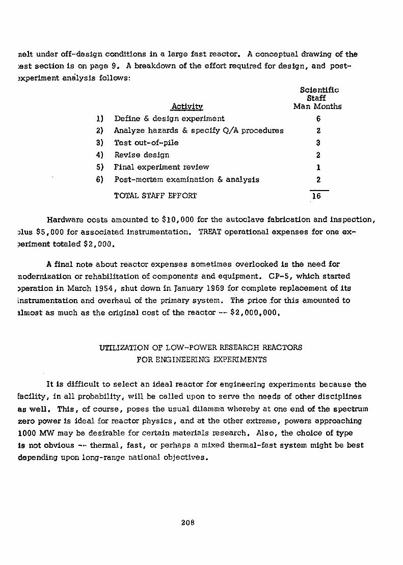
nelt under off-design conditions in a large fast reactor. A conceptual drawing of the«st section is on page 9. A breakdown of the effort required for design, and post-sxperiment analysis follows:
ScientificStaff
Activity Man Months1) Define & design experiment 62) Analyze hazards & specify Q/A procedures 23) Test out-of-pile 34) Revise design 25) Final experiment review 16) Post-mortem examination & analysis 2
TOTAL STAFF EFFORT 16
Hardware costs amounted to $10,000 for the autoclave fabrication and inspection,alus $5,000 for associated instrumentation. TREAT operational expenses for one ex-periment totaled $2,000.
A final note about reactor expenses sometimes overlooked is the need fornodernization or rehabilitation of components and equipment. CP-5, which startedoperation in March 1954, shut down in January 1969 for complete replacement of itsinstrumentation and overhaul of the primary system. The price .for this amounted toalmost as much as the original cost of the reactor — $2,000,000.
UTILIZATION OF LOW-POWER RESEARCH REACTORSFOR ENGINEERING EXPERIMENTS
It is difficult to select an ideal reactor for engineering experiments because thefacility, in all probability, will be called upon to serve the needs of other disciplinesas well. This, of course, poses the usual dilemma whereby at one end of the spectrumzero power is ideal for reactor physics, and at the other extreme, powers approaching1000 MW may be desirable for certain materials research. Also, the choice of typeis not obvious — thermal, fast, or perhaps a mixed thermal-fast system might be bestdepending upon long-range national objectives.
208
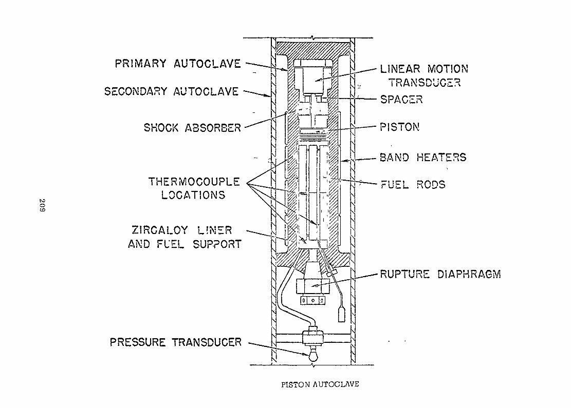
1CoCO
PRIMARY AUTOCLAVE
SECONDARY AUTOCLAVE
SHOCK ABSORBER
THERMOCOUPLELOCATIONS
ZIRGALOY LIMERAND FUEL SUPPORT
PRESSURE TRANSDUCER
LINEAR MOTIONTRANSDUCER
SPACER
PISTON
BAND HEATERS
FUEL RODS
RUPTURE DIAPHRAGM
PISTON AUTOCLAVE

To establish boundary conditions for the list of engineering experiments tofollow, a reactor power of one megawatt or less was considered a reasonable compromise.Initially, the facility could be operated at low power for training and physics investiga-tions. Later, with the addition of heat-exchange equipment, fluxes up to 10*^ nv couldbe reached so that the reactor could then serve as a source for exponential experimentsor be used to study irradiation-damage effects in selected materials. Some examples ofengineering topics that are compatible with low-power research facilities are:
Fuels and Materials
materials quality control by activation analysis
determination of control-materials worth by danger coefficientmethods, etc.
development and test of thermionic and thermoelectric powersupplies
irradiation-damage effects in semiconductors, lubricants, plastics,and certain metals
. gas release and diffusion within fuels and control materials
radiation effects on thin magnetic films
. radiation effects on materials conductivity
. diffusion of fission products through clad materials, graphite, etc.
. efficiency of shield materials
.Instrumentation and Control\ ' /
. investigate control automation systems
. investigate chemical control techniques and backup safety systems
. subcriticality monitoring and reactivity memory devices
. development and testing of radiological safety instruments
, reactor dynamic behavior and response to control malfunctions
development of self-powered detectors
. investigate failed-fuel detection and location schemes
. development of wide-range flux-monitoring systems
210

in-core testing of out-cf-core detectors for higher-powerreactors
. irradiation damage to safety-system components, such as solidstate devices, insulation, and magnets
. develop techniques for in-core flow monitoring utilizing coolantactivation
evaluation of control elements using moderator-poison combinations
Heat Transfer
flux distribution in fuel clusters
transient behavior of heat pipes
. effect of radiation on sodium superheat
effect of radiation on nucleate boiling in water
Chemical Engineering
effect of radiation on corrosion kinetics and surface reactions
. effectiveness of decontamination procedures
Reactor Engineering
•imriaa-HrfjMHori r\f rp>n<~t-i tni-Tj fpxcirîH^nV -from dtmr-tiirAl di^f^rHnnV •.-* . —— >v ~—£/ —— '——• — -- ~ — ~— —— * •— . — ~.J . . . . . . . . . , — — * . . „ . ._ ._ . » , . — — w . . _ . — — *.„ ^ . _ w _ . _ v v w _ _ f
such as bowing of fuel, in exponential experiments
flux distribution in irradiation capsules and mockups for calibrationof experiments prior to insorlion in a test reactor
. detect vibration of fuel bundles or materials displacement duringflow tests by reactivity perturbations.
SOME THOUGHTS ABOUT COST REDUCTION
Improvo Utility; of..Low-power Reactors
Experimental ingenuity has frequently been an economical substitute for higherreactor powers. A good example is the use of cryogenic techniques to improve signal-
(3)to-noise ratio in irradiation-damage studies. Money spent to develop better counting
211
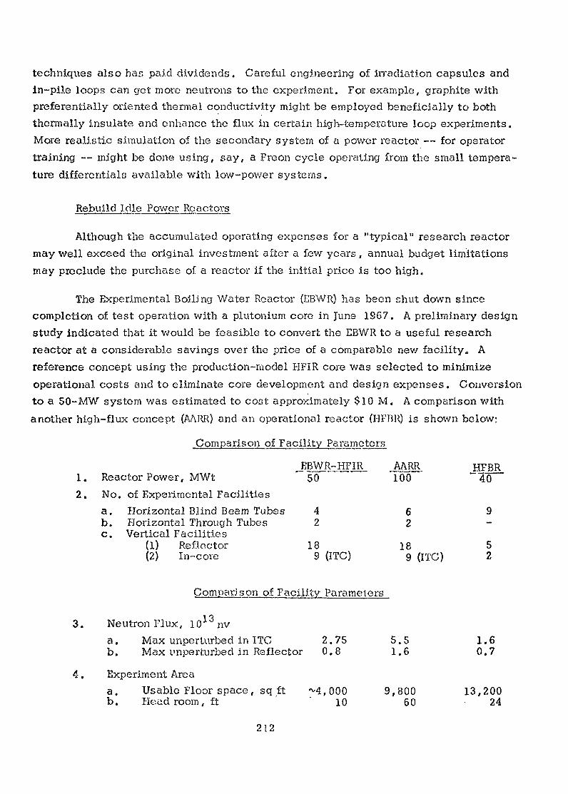
techniques also has paid dividends. Careful engineering of irradiation capsules andin-pile loops can get more neutrons to the experiment. For example, graphite withpreferentially oriented thermal conductivity might be employed beneficially to boththermally insulate and enhance the flux in certain high-temperature loop experiments.More realistic simulation of the secondary system of a power reactor — for operatortraining — might be done using, say, a Freon cycle operating from the small tempera-ture differentials available with low-power systems.
Rebuild Idle Power Reactors
Although the accumulated operating expenses for a "typical" research reactormay well exceed the original investment after a few years, annual budget limitationsmay preclude the purchase of a reactor if the initial price is too high.
The Experimental Boiling Water Reactor (EBWR) has been shut down sincecompletion of test operation with a plutonium core in June 1967. A preliminary designstudy indicated that it would be feasible to convert the EBWR to a useful researchreactor at a considerable savings over the price of a comparable new facility. Areference concept using the production-model HFIR core was selected to minimizeoperational costs and to eliminate core development and design expenses. Conversionto a 50-MW system was estimated to cost approximately $10 M. A comparison withanother high-flux concept (AARR) and an operational reactor (HFRR) is shown below:
Comparison of Facility Parameters
_AARR HFBR1. Reactor Power, MWt 50 100 ~ 402. No. of Experimental Facilities
a . Horizontal Blind Beam Tubes 4 6 9b. Horizontal Through Tubes 2 2 -c. Vertical Facilities
(1) Reflector 18 18 5(2) In-core 9 (ITC) 9 (ITC) 2
Comparison,of Facility Parameters
3. Neutron Flux, 1013 nva. Max unperturbed in ITC 2.75 5.5 1.6b. Max l'nperfcurbed in Reflector 0,8 1.6 0.7
4. Experiment Areaa. Usable Floor space, sq ft M,000 9,800 13,200b . Headroom, f t ' 1 0 6 0 2 4
212
Significant savings could have been realized because many items would have beenreuseable, such as: a) the containment, structure; b) fuel-transfer and storage facilities;c) reactor vessel; d) shielding; e) building services and emergency power facilities;f) certain parts of the instrumentation, piping/ and heat-exchange systems. A majorfeasibility question concerned the irradiation damage received by the type SA212B steelpressure vessel during previous operation. It would have been possible, however,to locate the new core within the lightly exposed upper region of the vessel. It wascalculated that enough shielding could be obtained by partially filling the vessel withwater to permit access to the upper portion for the required construction changes.
The cost estimate for this conversion would have decreased if the reactor weredesigned for irradiation service only; thus, eliminating the need for beam tubes.
DEVELOP METHODS FOR SALVAGING ANDMARKETING USED RESEARCH REACTOR COMPONENTS
An interesting facet of reactor economics seems to be the negligible resale valueof used reactors. One non-AEO-ov.;ned 50-kW raactor known to the author recently wasavailable free to any qualified user who was willing to take it away. It is conceded thatIt might be impossible to transplant economically certain radioactive or contaminatedpaxts. Nevertheless, a diligent search among the many reactor facilities that havediscontinued operation can yield components of value to new installations. Alternatively,reactors scheduled for shutdown because their original objectives have been satisfiedmight still be useful research and training tools for users in other countries who couldsupoou operational expenses»
INVESTIGATE TECHNIQUES FOR UTILIZATIONOF OPERATION, POWER REACTORS
Coupons have been routinely irradiated in power reactors to monitor the effectof the environment .on pressure vessel materials. Without risk to plant factor, morelong-term materials experiments might be run in unused lattice positions within thecore.
In addition, external neutron irradiation facilities might, for example, be ob-tained relatively inexpensively with the addition of a beryllium photoneutron sourcedriven by gammas taken from the primary system piping.
213
CAREFULLY SCREEN IN-PILE EXPERIMENTS
• < ' . -
An obvious, but sometimes neglected, way to save money is to review criticallyall in-pile experiments to make sure that they are needed and will yield relevant informa-
' " ' ' < ' " - , • > '
tion . In particular, experiments that call for the usa o* a reactor to supply thermalenergy should be examined to see whether there is a cheaper, out-of-pile alternative.
If the test reactor environment ca'nnot be monitored accurately enough to deter-mine that it simulates the desired conditions, then it would be prudent to develop betterinstruments before doing irradiations.
Frequentlyf where statistical evidence is needed, insufficient data are collectedfrom in-pile experiments to resolve major uncertainties before time and money is ex-hausted. _ . , . , . .
Finally, the correspondence between the in-pile data collected and the solutionof a particular design problem may become so tenuous that analytical methods might beprofitably,;substituted for experiment
ft- ,
.REFERENCES
(1) "The Instrumented Subassembly System in EBR-II", A. Smaardyk,C. Divona, E. Hutter - Trans.. Am. Nucl. Soc, 13, 355 (July 1970)
(2) "Fuel-Failure Behavior During Transient Meitdown in a Sodium-Filled Piston", John J. Barghusen, Bonn R. Armstrong, James F.Boland, Robert W. Mouring, James C. Hesson - Trans. Am. Nucl.Soc. 12, 863 (December 1969)
(3) "Low-Temperature Irradiation Studies", T. H. Blewitt, ArgonneNational Laboratory
214

Questions arid/or Comments
The examination of the U.S. programme over the years shows yourpoint of taking out of service various materials test reactors, notonly MmR but some of the commercially owned ones too, and. "bringinginto service the safety oriented test reactors.
It seems that the U.K. tsro^ramme shows the first step of thistoo with the decommissioning of D.M.T.H. Could you see any waywhereby the maternais test reactors could have been built so thatthey could have been subsequently modified for safety aspects, or is itabsolutely essential to build a new reactor for this different objective ?
T think, with foresight there are ways in which these reactorscould be designed so that they could be converted at a later date andif not, T think, that many of the components of these reactors couldbe used as a nucleus for new systems. Actually, considerable savings canbe made if in the beginning you plan for the future with all the fore-sight that you have at your commend.
215
SCOPE AND POSSIBILITIES OP ENGINEERINGPROGRAMMES IN THE U.A.R. RESEARCH REACTOR
M. P. El-PoulyU.A.R. Atomic Energy Establishment
Cairo
Abstract
A brief description of the several -problems that faced the U.A.R.Atomic Energy Establishment in the preparation of trained personneland ecu-: pr ing laboratories is presented.
A .description of the research work taking place in the fields ofcontrol. heat transfer and material properties is given.
Hopt of the research work in process is meant to support the foalof designing a single purpose re.actor for desalination.
IntroductionThe United Arab Republic Research Reactor àt Inchas Isa
tank type, water-cooled and water-moderated of Soviet design andmanufacture. This type of Reactor is designed to furnish reasonablefacilities for Physics research in the branches of neutron andreactor physics besides its main purpose .of producing medium livedisotopes and furnishing irradiation facilities for biological andsome agricultural-, research . The reactor was since its ine u-m.); i onin July 1961 - utilized for the above purposes,. ..The. reactor .and..neutr-on physics. .research proceeded while .reactor,,. engineering re-search- --was .still .in the process of formulatipn « }n .planning .for ,engineering research it was important, ..to. prepare personnel qualifiedin reactor engineering branches and to provide additional facilitiesnecessary for this type of .research. .Besia.es.» it, was important toselect from the many aspects of reactor engineering research thesewhich may have direct contact with our regional problems and whichwould need relatively little expenses.
217
2. The Research^Reactor as a Training Tool for EngineersAll the reactor personnel present at the time of the reactor
inauguration were not basically qualified as reactor engineers. Soit was the most "urgent task to have them trained in reactor dis-ciplines. This was done at first in several countries abroad untilit was possible to do it at Inchas. A. reactor school was formedat Tnchas using the reactor facility, graduates were given formalcourses related to reactors such as neutron and reactor physics,reactor control, reactor theory, reactor heat transfer, fluid flow,and reactor dosimetry. The courses usually end in a detailed des-cription of the UA-RK-1 reactor system and practical training in itsoperation and maintenance, graduates from this school were responsiblefor the reactor operation besides taking part in research projects.
Practical training covers the method of calculating criticalityand other reactor parameters and the comparison with existing reactorconditions, simulation of reactor core behaviour and non-boiling heattransfer calculations were carried out in order to have better under-standing of the reactor working conditions. Experiments in reactorstatics and reactor kinetics were carried out such as flux mappingand control rod calibration; burn-up calculations were given specialattention. Accurate evaluation of heat transfer time constants in theUAR,R-1 fuel rods were made. Boiling problems in reactors were alsostudied by experimental simulation.
3» Power ProgramsIn the year 1964 the United Arab Republic found it necessary
to start studies''for the first power reactor to be installed at a sitanear Alexandria.1 It was very obvious that at this time we lackedpersonnel capable of evaluating the tenders submitted by internationalfirms. It was necessary to have the help of a consulting firm. Itwas decided at thé same time to start preparing a group which coulddevelop, and design reactor components or projects as required.
National Power and Desalination ProgramNational requirements for power and desalted water were studied
and a decision was reached* to start design studies for a single
218
purpose des&li-nafriorr reactor using natural uranium as fuel and knownmaterials for 'dad-ding-. A committee was formed to di rect;'research inthe different fields- of study towards this goal •
This decision meant the necessity to strengthen engineeringresearch in hhe reactor center. A program was initiated covering someaspects and topics in engineering research,, two main factors were takeninto account in- the choicer of' the tories to be studied :
1. The limited funds available2. The limited facilities' to start with.
• 'Of xAspects of the EMgln'ee>ing Programs N - >
y - L •« 'The research program selected different tonics within thec
following fields :1. Beactor fuel and materials properties2. Heat transfer and fluid flow3. Control and instrumentation development4. Cost analysisTo fulfil this program, .laboratories we re s provi de d with the
necessary equipment.; / i-.r<- - 1-
A . Heat Transfer , , . . - , r<•) The problem of, heat transfer inchest e^changefs-'ànâ'react or
channels was studied. The frequency methods of analysis were used'i- ' " ' " •- - "1 s" ' ' '
in a dynamic analysis of a counterflow and parallel f}ow.he.at ex-, . i t - • -i ' i"changer model. It was shown that the method, which can be appjie.d
uz- -f voe'^'M » f v - >•to any linear system, is relatively simple and can bç considered assvo'K- *, .° ! ' J 'a standard method for heat transfer dynamic analysis. The pesults
-O V 4 - rf, f,-,- - „ " ' '
of calculations agreed with measurements.
In a frequency and spectral analysis of characteristic ''temperatures in a reactor channel, an analytical solution based on theconsideration of a distributed parameter system was given,for determin-ing the dynamics of the reactor channel. This(work has shown thatthis analytical method is a reliable engineering tool for studying thedynamics of relatively complicated systems such as reactor channels.
219
Transient heat transfer in a reactor channel model was alsostudied theoretically by exact treatment using the Laplace trans-formation. Experimental measurements were made on the responses ofthe coolant temperature in an out-of-pile channel and of the heatersurface temperature to step changes of the electrical power in the heater.
Experimental work in heat transfer was then pursued withimproved equipment to cover heat transfer in annular reactorchannels in the case of steady—state forced convection in thetransition and turbulent regions. These tests were conductedfor different heat fluxes (up to 1.975 x 30 Kcal h~ m""2) in thetransient and turbulent regions of flow (2.1x10-* N- 1.0 x ICr)and correlations were established. Comparison with previous workin the field was carried out.
An interesting and powerful technique for solving diffusionproblems is worth mentioning here. This is the electrolytic tankanalog, which was used successfully in our laboratory and wasextended to solve transient heat diffusion problems for cases ofmultiregion with different external and interface boundary condi-tions. It was demonstrated that it is possible to use such modelsto get transient cross-sectional, two-dimensional temperaturedistributions in reactor fuel elements. By using the availabletechniques and materials in our moderately equipped heat transferlaboratory, this geometrically complicated problem was readily solved.
Two phase heat transfer has been given special attention»Experimental investigation of the cooling of a uniformly heatedtube simulating a fuel element forming the heating surface of anannular space by naturally circulated boiling water is aboutcompleted. The investigation shows that accurate prediction ofthe surface temperature of the heater cannot be made withouttaking into consideration interference and end effects.
The effect of contraction of flow channel or heat transferis being worked on, this type of heat transfer problem has notyet been fully investigated. It is hoped that this study mayfurnish some data for the calculation of heat transfer in cond-itions with positive and negative pressure gradients. This problemsimulates the case of spacers fixing the fuel rods or plates ina fuel element.
220

Measurement of temperature field in the two phase flowis underway. By getting information about this problem it ispossible'to gain more knowledge about the processes which playthe main'-role in the change of the flow pattern. This study isconsidered of importance for the nuclear power reactors as mostof modern boiling reactors are working within this type of flow-in the fuel channels.
We are also studying the effect of solid additives on boilingheat transfer and burn out heat fluxes, one of the most persistentproblems in reactors. The influence of impurities on boilingprocesses is far from being known. Its influence on burnout heatflux is a very important factor in considering the hazard evaluationdue to fuel burn out.
An experiment to measure the properties pertinent to thermalconduction of materials used in nuclear reactors by using unsteadystate methods is hoped to help in understanding the heating be-haviour of fuel in reactors.
Other points of interest which are being investigated orwaiting for supplementary equipment or finance are mentioned below :
1. Investigation of scale formation on water heated surfaces.2. Effect of geometry on mass transfer in flash evaporators.3. Pool boiling of pure liquids with dispersed solid particles.4- Burnout heat fluxes and its detection in flow boiling.
B. £ontrol and AutomationThe research reactor has many of the physical and technological
parameters of the power reactor, it has a]so its design flexibilityas a-research tool. With the above in mind it could serve as a use-ful tool for proofing.engineering methods of instrumentation andcontrol of power reactors as well as other more general types. Thisis a much cheaper way than using a proto type power reactor forsuch development.
Examples of problems on measurement and data processingwhich has significance in power reactor engineering and that can besolved using research reactors is the on line flux pattern estimation
221
and the development of on line methods for reactivity measurement.For control, the research reactor could be used as a proofing groundfor modern advanced techniques and complex automation systems usingdigital computers. The reactor has elaborate hack up and safetysystems which are necessary for such type of experimentation. Afterthe systems are developed and tested on the research reactors, theycould be carried over to power reactors. To mention some such problemswe have minimum time start-up und aeval change with physical andtechnological constraints. The optimal-load follow-up, a problemwhich is important for non-base load operation of nuclear powerstations. The use of on line computers for complex automation andfault analysis is another area where the research reactor could beused for useful development work.
The control laboratory at our department started its activitiesabout four years ago. Work began by building different types ofanalogue instruments needed to improve the existing control andsafety system of our reactor. Furthermore elaborate analogue anddigital blocks for parameter estimation and sequence control weredeveloped and implemented. A study of the system aspects and theapplication of modern control methods followed. Then a suboptimalstart-up system using the above mentioned blocks and developedalgorithms is being tried. Work will start soon on an on-linedigital computer experiment for reactor control and data logging.
It is hoped that by supporting this line of activity incontrol the Atomic Energy Establishment could contribute to thedevelopment of the technical know how needed to tackle otherindustrial processes and control problems of national interest.
Different aspects of international cooperation could enhancework in the above field. The quick supply of diversified componentsand transeducers in little quantities on an interlaboratory bases.The establishment of a periodical to publish regular contributionsin the field. The exchange of technical staff for a period of oneyear or more and work on joint projects financed by more than oneside.
222

, Cost Analy-sia ... . ,
•". ~ Studying 'power realtor economics and organization have notbeen neglected. The studies are directed to help developing countriesin their decision for starting nuclear power programs. It also helpsgiving an idea to developing countries about the cost, consideringlocal conditions and the degree of participation with its directeffect .cm .finance, and foreign currency needed.
Pub lie at ions
1- BARTCKOUK, I.I1. ZAALOUH, M.G. IUITRY.A .1,1.. --V/L. 7 '
Nuclear Fuel Consumption, in the UA-RJLl-1 Reactor.UAR AJ&J Hep. 50 (1966).
2- SULTAK , . A» fciQitoY , il . ô .: ' . ' ' -•'P'ïui'ix; •'. .A study of the Automatic Feedback Control System of theUA-RR-1 Reactor, UAR AMD Hep. Int. 8 (1966).
5- SUIM^M.A. MOHoY, M.S.An Oscillatory method for Determination of The Neutronlife time in UA-HR-l Heactor by Using The Automatic ControlSystem, UAfi AEE Hep. 53 (1967).
4- ZAALOUK, M.G,An Accurate ^valuation of The time Constants in The
v .' S, W • ' -
Transfer Function of heat Transfer in UA-.RR-1 Fuel RodsUAE AEE Hep. 56 (196?).
5- ZAALOUK, M.G. HAGAB, H.A«Experimenta-.l .SI.Hxy.ilation otudy of Boiling in Reactors,Arab J.Nucl. Sci. Applic. 2(1) , (1969)pp 77*
6- FERETIC, I). , HILAL, IV..M.The Dynamic analysis of a model of counter flow and parallelflow heat exchange- UAR AEE Rep. 25 (1966).
7- SULTAN, M.A. FiCRETIC, ]).Frequency and opuctral Analysis of Characteristic Tempe-rature in'vReactor Channel , Atomkernenergie ll(1966)pp 411.
8- FBEETIC, Û. , HIIAL, M.M.,Transient Heat Transfer Model of A reactor ChannelUAR,AEE Rep. 16(1966).
223

9- HILâL, M.M» , RAAFAT, N*tf. MITRY, A «il»Heat Transfer in Annular Reactor Channels Steady Stateforced Convection in The Transition and Turbulent regionsUAR ABB Eep. 50 (1968)*
10- Elr-PQUItf, M.F* f SHAPE, J,K.Organization for a Nuclear Power ProjectUAR AEB Rep. 41(196?) .
21- Elf-FOULY, ££«]?« Eucltov.^ 3aer&/ Costs and Economic Develo-pment (Proco Symgu Istanbul , 1969) t IAEA, Viennal (in press)IASA-SM-126/59,
12- BL-FOULY, M»P«, Itemized analysis of nuclear power costsArab J«Huclo Soi, Applice (in press),
13- BL-JSOFOJT 0,Eo Hole of Research Reactors In Reactor Develo-pment Program» Peaceful Uaed Of Atomic Energy In AfricaProco Symperice Kinshasa (1969),
14- M.A.Hassan, M.T«Azer, M,A,R. GimoaimyA computer evaluation of Reactor Start-up algorithmsPaper presented at the Seminar.
Application of on-line computers to nuclear reactors»Sandefjords Norway, Sept(1968).
15- LJUA.Hassan, F «A» GrinevichTransistor amplifier for measuring weak DC currentsPribory i Tekhnika Jiîxperimenta
% 5» PP 137-139» May-Jun(1969)16- M. A, Has 3 an
Iterative Procedui e ror De-o aaiining the BestControl- Weighting MatrixElectronics Letters
Vol. 5» NO 18 , 4th Sept. (1969),«"" λ
17- M.A.Hassan, M.Ï.Azer, M.A.R. Ghonaimyi On-lineEstimation of Reactor Parameters From NoisyMeasurementsPaper Presented at The Panel
Instrumentation for Nuclear Power PlantsControl .Vienna, Austria, Nov. (1969)»
P. A,224
THE USE OF, THE RESEARCH REACTOR IN BULGARIAFOR SOLVING NUCLEAR POWER PROBLEMS
R. Georgiev
ABSTRACT
The paper makes a survey of the work which has been, and is being,carried out at the research reactor in Bulgaria for solving problems ofnuclear technology. Special attention is devoted to nuclear power studies.Of the problems being handled, those which are connected directly withthe construction of nuclear power stations are enumerated in detail.Mention -is also made of the methods used for training nuclear powerstation personnel.
B jDiOKjiaj.e .uejiaeTCH oôsop padoT , BbinojineHHbiy na
peaKTOp." B EojrrapwH, KOT optic pemawT npod.neMH
T e X H W K W . OcOOOe BHMMaHMS yjLGJlfieTCfl M C C J i e ^ O B a H H H M , CBHSaHHBIM."">'< ,f
C fl^eX5HOM G H e D r e T H K O M . "B M a C T H O C T M nepeMMOJTHIOTOH paSTDaoaTHBa
Henoc"DejcTBeHHO cBnsaHHBie co CT'ooHTej ibCTBOM A3C.
TaKsce cnocoow, KOTOTDBIMH no.Jib3,ywTCft nnw -pemeHtfH nr)o6.ieM
Kajinos JI.TH oKcnJiyaranMM A3C.
peaKiop aToimoro iieHTpa BoorrapCKoftHayx «B^wteTCfl peaKïopOM dacceftKOBoro THtna MOIUHOCTWO
2 000 KBT, snocjieACTBMH yBejïiroeHHOîî , B peayjriTare HOKOTOPHX2 800 3 000 KBT Tenjiosinc. OH coopyxeH dooiii
KOJIHMeCTBOM rOpH30HTaJIfcHKX K BepTHKOJIfcHIJX 3KCnepHMeHTaJI!>
HHS: KaaajroB - scero 23. PeaKTOp naxoAUTca B sKcmryaTauKH c1961 ro,sa.
o MMCTO $H3H^eoKnuK aKcnepHMeHTawH KHSOTonoB Ha peaKTOpe Bcer^a aaHHiiajiK no^ernoe
HHacenepiaie npoOJieB«H K npes^e scero npoCjieMM,
225
IÎBK TSOpeTH^ecKit© P&COTH noB pa3HOp04HHX cpe^az - Bo^ocojïepsaa[MX H B0jtopo.no-,- TÛJS « oojaysemie oSpasiîOB paansnc acaTepaajioB c
Baxnoe isecTO B OTHX paspadOTKax aann-ci^aannoe c norjïomeHKeM rain«a-
H /rjtepHMMH peaKitïBîsîïi pacceHBaHHH M aôcopGnHH Heftxpo-HOIS. B pesy-KbTaTe sardpaa :iOM0H;cJiaTypHKcS pna crpyKTyp, KO-Topwe npKMeHiï!OTc« B cTpoMTejî&CTBe Â3C» Pac^ieTw se^yTCflt Ha3JïeKTpOHHO-BLFïHCJIMTG,ïîî>HOË MBElKHe HO Cn6ïï[MaJÎ&HO
nporpaMMe «
s BHjïy TEtn anepreTHiecKaz peaKTOpoB, KoioptieB Haraett cTpaHe no KpaMneîi Mepe BO 1980 ro^a, a
HO poaKTopsi HOBODOpOHOKCKcro Tiina - Kopnycttwe c odBWHOft so^ottB Ka^ecTDe TenJiOHocMT6Ji« - y nac y.çeJweTC»
HB XÏÎMïtSï SOJ5SÏ H npOt5jI©My KOppOSHJÏ
OHHSEC ssaTspiiajioa penKTOpos»
Ô$$QKÏIÏBHOCTI, paajiHMHHx BKJÏOBCMOJÎ, npHueHjieaojx ^JiJï o^iii^eHH^c EJ.HBI, a raicse KHHeTHKa HOHO-
npoijeccoB. B HacTO^ujee spetiA nocTasjiena aa^a^iaoneECH(|)HKy "nay^sKc npoi^ecca" npMMeHHTeJibHO K nepBOMy
KOHTypy M paspadOTKa CJsrcTpo.neiicTByiomero $KJib-Tpa, paCoTaHffifero Ha ajiaittrpOMarHHTHOM
B OTOM qacjie H xaïaie HenpepHBHoroJUKI onpe^eaeHHJî DJieKTponpOBOjptMOCTH BO.BM M 4pyr«x
napaaierpos, K&K BejrnvHKy pH. HocBe^aeTCA HeoOxo^Kwoe BHHiiaHHe6opi,5e c Koppoawefi H peryjiKposaHHio $aKTOpoB, BJIHJIK^HX na Kop-
nporçeccBi» Ocoôoo SKa^eHHc .UJTJÎ HaniHX ycjtOBMiî B
226
CBHSH co CTpo/irçHMMc« SHepreTKreecKHMH peEKTopaMH HMeîOTo<5H&pyxeHH«
TB Bwjiy ocBoeiiMe «mgrs
rpynnoBoro peryjmposaHKA MO^HOCTK peaxTOpa H
KeSTpOKOBfMKAyi^Kpyess&ix nonepsoro
K ocodeHHo sasHBiM npocJ^esgaM jt?,jwî nac cjseayeT OTHSCTHXHMHH BOJIM, co^epstai^eft oopEyio KHCJIOTJ B
opraaa KOMneHcaarHH peaKTstxmoeTH peaKTOpa.
yenjTQgepejra<iag
aKTMBHOM 30H&I
TeopeTK^ecK«e pac^eTM teMnepaTyp
BO3SÎOKKQCTE "CHHT&" MaKCHMaJîfoHyiO MOQHGCTb C aKTEBH©iî 3OHH OOH®Ba~
KH Ha JIOKSJIbHMS: 3HaieBM^2£ HeitïpOHKOrO HOTOKa B aKTHBHôft 30H6 «
BtidpaHHofi Me-tQjJMKQ pac^eTOB. MeïQjîMKa sa%na KEK .QJJA npoeKTHpoBaHH«,ran H AJIH 3KC£uryaTamfH B paSeiax JCJÏÔBKHX,, .HJIH nac Kaaajioci» Ban-HbiM nposepHTi» MexoAEKy, Kôïopyio npHHfljm B pac^erax, H naatony HaHccjiejieBaTeji&cKOM peaKfope ap&sejcK aKcnepRMeRT HSMepeHHH peajii,-m>nc Tetmepatyp Ha nsBepxaoCTH SB -• no aucoTe » no&COK aKTSBHoM 3OHK npH pa3HB£K pacso^ax TemioHecHTeji^ m npuHQM noJiOKeHEH peryompyw^HZ CT€»PKH@^. Ha HacfQHmeM 3Tane
B
3-HeKTpoHHoro owMyjtHropa gMamitHH ^Jjg ynpaBjreKgJi
Haiara paCofa no cea^aKHro 3Ji®KTp©HH©r© ycTpoftcTsanp@i^ecc©B ynpaejraHKH peaKTOpaMM*
227
spesKHra onomnajmc^oB no ynpaBaeiœioHaoT9«nraii s tan wiepH©-sKepr8<!?s';iecK@r& paasMYiws i nameit CTpaue
K©HTPOJI« peaK-ropaMK B3BM
HanpasjieHH K
y nacss ccnapuposann^
aarpASHenzousiî no
KOCTH $©pMan^iî. lia, K®?opHO csaaajîH c I^iFÂTd
c®pd8H?u cejieKK©fttn»iioHï«>D 3
B
y Hac
Ha
Ha-sa HoOoji&ïaere Ksfâ^poHHoro noTOKa naioero peaxvepaB odJiacïE Ad$@K?®B KOHovpyKQÇEdHH&sx Ma?dpnaj!OB A^^ peaxïopoB
H9B03M©KKW. OjjHaKo aa peaxTope nposiasôaisïc^ od^y^emie rpa<jKTOBwa:HOA
a îawze peota »ÎIpcn8B©AK70« îgatsa odJiy^ieHHe cyxore
TOnjIbHOOEÏOJÏH JUH OTpaOo-ÏKÎî (ÎHCTpor© MQTOJia aK?HBaiQIOHB9ro
c nejibîQ HAGK¥H$iiKai;^n npKMocett mt ^TO canoë Baxaoer
, KaK Bi, Pe, Pb m ^pyrjie, odpaai^ us HEXc o^HQBpeiîeHHwa naMepe^ien ?eunepaTyp B
228
C©TpyjftHHKH MQCJiejioBaTejibCKoro peaK^opa npHHJwm aKTHBKoeB cocsaBJieHHM y«i0 dHbix nporpaMM &JSH cpejiHHX ISK©JI no aaepHoMH JïflepHQÎt 3JieKTp©HHKH , a TaKKQ B CdCTaBJZeHHK HporpaMM
À3C.
BTK Kypon dy^ty? np®8©j^?&cn peryjrapK®, noKa He@HM
A3C « B
pa aKTep_a_A9C.
B HaoTo^oiee spena B cTpoMTe^BCTB© Hax@^itTC^; nepsas A3C BoJirapHKIlepBHit peaKT©p MoDiHocTbto B 440 MBî(aji) BOÎÎAST B sKcnayaTaiçKto B1974 ro^y. OcTajifeHHe rpn peaKïepa xaKolî ace M©mHocTKB cfpoit B npoueaeyntax Ka«j(He rneofi» ueoJot@B
Â8C 1760 MBT(SJI)« Ente JLO OKOH^aHHK nepsoS A3CHOBHX A3C c Cojïee KpyrtHBfflm peaKïopaMH, ïaK STO B
corjiacMH c rocyjiapcTBeHKoiS «^epHO-SHepreTM^ecKoM nporpaMMoM K1980 r. MOQHQCTI» A3C .gocTHrHQ-r ne M@Kee 3 000 MBT(SJI).K do.n©e tieTKouy npHo6m©KHio Kcc^ejioBa?ejïbCKoro peaxTopa K
3HepreTHKB» K nepBofô A3C coajaaeTOH ^eH^?p HayMHWx srccjje-. OH npK3saH pemaT& ôojibmeM oô'BeM HaytiHo-texHU^ecKKX npodJieM,
Macrt. KOÏOPBTX: Gysys cv^saHa c HcnoJibsosaKsieMpeaKTopa. T3y,geT aneTfc MBCTO aratpoKoen;eKTpoM H nepcoHajroM peaKfopa.
HOBBIX npo6jieM,
229
pajsaoMeTpmiecKoii annapaïypH ASO. HamepeHna raaoaottH soJïtHoJi aK7HBHocTK s aTMoc$epe Boitpyr A3Cj
HeaeoTpyKTHBHorQ onpe^ejïeHHJi rjiyOEHw BiiropaHHaTonjmaa otpaCoTaHHoro s aKTHBHoft sonej
ajtorapH$MOB A-HH pacneTa ua 3BM TonjiMBHoro miKJia3OHK C JieJltV) AOCÏHK6HHH MaKCHMaJIbHOfi TJiyÔKKbl
Ses coMHeHna» <3yjtyiuee BBWBHHeî ente doJibme H doJiee cjio«HbDcnpodJteM, KOTopHe noïpeOywT pejneimjï na HccjieAOB-iTejtbCKOM peaKTope.
IÎM6J3 saxHocTb odcyKJiaeMHX na OTOM coseataKKH npodJieM, MbiAreH7CTBo K&R MeKJtyHapoflHbift ^eHTp B odjiacTH impHoro
aTOMHoiâ aueprHH jtonKHo H B 4iajii»HeiiineM pasBHsaTbcoïpyAHM^ecTBo nyreM npoBejieHHJî Taxoro se pojia
HHTepec npejicTasjiaeT taKste coBpeBpeMeHHbrii OÔMCH HH<£opMaiJ(BeiiymecTBeHHyio noMouib npH .naHHbix o<5cTOHTejn»cTBax AreHTCTso
paaBHsarontHMca cypanaM nyseM HajiaatHBaHHJi CTHJKHPOBOK cne~B pasBHTiix cTpauax.
Questions and/or Comments
How mxich IK the local industry participating in the constructionof the power reactors you have planned, i.e. what are the componentsmade in the country that have/use'd in these nuclear installations ?Especially, what is the situation with regard to the fuel elements ?
Regarding these components, the entire equipment for the primarycircuit, the turbine and the generators are imported, the rest - avery important part of thene installations - will be produced in thecountry. The nuclear fuel elements will be entirely imported fromthe Soviet Union.
230

USES OF TRIGA RESEARCH REACTORSfor
ENGINEERING, RESEARCH, TESTING, AND TRAINING
byG. T. Schnurer, A. T. Me Main, and P. U. Flscher
TRtGA REACTORS, GULF ENERGY £ ENVIRONMENTAL SYSTEMS, INC,P.O. BOX 608, SAN DIEGO, CALfFORNfA 92112
INTRODUCTION
Today research reactors are universally accepted as important researchtools, but all too frequently they are associated exclusively with scientificresearch. The scientific applications of research reactors, although stillvery important, are gradually giving way to an increasing number of appliedor engineering-oriented applications. With the growth of nuclear powerthroughout the world, research reactors are playing an increasingly importantrole, principally in areas of training and engineering research.
The information presented in this paper is drawn from the experiencegained in the operation of three TRIGA reactors at Gulf Energy and EnvironmentalSystems, Inc. (GE&ES) and also from the experience accruing from the instal-lation and operation of nearly fifty TRIGAs throughout the world. As a survey,this paper treats briefly a number of different applications which illustrateways in which a relatively low-power reactor such as the TRIGA can be employedproductively in engineering research. This paper also illustrates an importantcharacteristic of all research reactors: they are interdisciplinary tools thatcan be used in a variety of different fields. Since many countries embarkingon a nuclear power program do not have access to expensive high-flux multi-megawatt test reactors, examples have been chosen from reactors operatingat a power level of 1 MW and below to demonstrate how such reactors can beused in support of engineering research, particularly as it relates tonuclear power development.
231

1. TRAINING
The role of a research reactor as a training device has been longestablished. In recent years, however, renewed emphasis is being placedon training to support an expanded nuclear power economy. In the UnitedStates, for example, it has been predicted that by 1980 the manpowerrequired to operate the number of nuclear power stations then expectedto be in operation will be at least 40 times the present working force.
In many training programs for nuclear power plant operators increasinguse is being made of power plant simulators. Even so, the role of aresearch reactor is still essential: the United States Atomic Energy Commis-
(2)sion has stated that in order to be eligible for cold examination evenindividuals who complete a training program using a nuclear plant simulator,in addition to other requirements must also have manipulated the controlsof any nuclear reactor throughout ten complete startups. Because thecost of obtaining such startup experience on & power reactor is prohibitive,more and more attention is being directed toward the use of a researchreactor for this purpose. A number of research reactors have already beenproductively employed in meeting this need. One specific program usingthe TRIGA reactor at Pennsylvania State University has been reported in
•/•t\some detail. One of the observations made during the conduct of thecourse at Pennsylvania State University was that the research reactorfacility used in such a training program should put proper emphasis onhow well the' trainee would be able to "see" the reactor in operation. Thisreferred not only to the ease of operation but also to the availabilityof other reactor hardware for viewing and handling. A pool-type reactor,such as the TRIGA, which permits the trainee to see the fuel elements inthe core, to watch the control rods moving, and to observe Cerenkovradiation is preferred to a closed-tank type reactor. In a trainingprogram it Is useful to the trainee to take part in the installation ofadditional instrumentation which would more closely represent the readoutsfound in the control room of a nuclear power plant.r ,
The basic aim of any training program is to instruct the trainee Incontrol and operation of the reactor. The metallurgical form in whichthe uranium is contained does not play a significant role in the teaching
232
of operating procedures. The pertinent characteristics of reactor physicsparameters, such as temperature coefficients, reactivity effects, voidcoefficients, and the like, are most important. The reactor used fortraining must have the best safety characteristics possible in order topreclude the occurrence of an accident or contaminating incident resultingfrom an error in judgment during training.
We consider pulsing to be an important characteristic since it isnot only indicative of safety characteristics but can be used in a strikingmanner to demonstrate prompt critical operation.
Although the foregoing comments refer mainly to the training of nuclearpower plant operators, the need for trained personnel to support theexpanding nuclear power economy ranges from technicians to professionalstaff. The present program will need to grow and new programs must beinaugurated to meet this demand. In addition research reactors will playan expanding role in providing training in numerous techniques that usenuclear methods. For instance, neutron activation analysis, the handlingof radioisotopes, and neutron radiography are a few of the techniques forwhich trained technicians will be needed.
2. NUCLEAR TECHNIQUES IN ENGINEERING
Worldwide utilization of reactor-produced isotopes in many industrialand engineering applications is well known and will not be discussed indetail. (For example the uses of radioisotopes in various gauging appli-cations and in gamma radiography have had a significant impact on industrialand engineering activities.)
Although less widely used, the techniques of neutron activation analysisand neutron radiography are also finding important and growing applicationsin engineering. For example, neutron activation analysis has found specificapplications in mining engineering. In mining one usually wishes to determineas rapidly and as accurately as possible, the concentrations of one orseveral elements of interest in rock, mineral, and ore samples. In therelated, more academic fields of geology and geochemistry, the interestin typical earth-crust materials may range all the way from major constituents
233

(such as Si, 0, Al, Fe, Ça, Na, K, and Mg) to minor constituents (such asTi, P, Mn, S, Cl, Rb, F, Sr, Ba, Zr, Cr, V, and Zn) to those elements usuallypresent at trace levels (e.g., Ni, Cu, W, Li, Ce, Sn, Y, Nd, Nb, Co, La,Pb, Ga, Mo, and Th) to those present at even lower levels. Work in thisarea is being conducted in Finland and at Pennsylvania State University.
In recent years, increased commercial interest in various rare elements,such as yttrium and europium, has enhanced the interest in neutron activationanalysis as a method of ore analysis. With a research reactor, the delayed-neutron method has proved to be very useful for the determination of uraniumand thorium. This technique has been pioneered and well developed by SaadiaAmiel in Israel; similar work is now being done by the University of Texas»as well as at a number of other facilities. Rocks, meteorites, and actualor potential uranium ores can be rapidly, accurately, sensitively, andnondestructively analyzed for uranium via measurement of the neutronsemitted by those thermal-neutron fission products of U-235 that decayby neutron emission. As little as 0.001 pig of natural uranium can bedetected by this method. With suppression of the U-235 fission by theuse of suitable thermal-neutron shielding of the sample during irradiation(e.g., with cadmium or boron), the fission-spectrum fast-neutron fissionof U-238 or Th-232 can be employed to detect amounts of these nuclidesas low as 1 ug. This technique has been used for measurement of thenatural uranium levels in meteorites by G. G. Goles of the Universityof California at San Diego, using the TRIGA Mark I reactor at the GulfEnergy and Environmental Systems laboratories.
Some interest has also been expressed in applying the above techniquesto examination of waste materials to detect low levels of fissile or heavy-metal toxic materials prior to their disposal. This area of work hasapplication not only in the field of nuclear materials management, butalso it is increasingly applied in control and detection of pollution inwaterways and contamination of marine and wildlife resources.
Various studies have been conducted on the identification of oil slicksby means of naturally-occurring trace elements. Increasing use of a researchreactor for detection of low levels of heavy mineral pollutants, such asmercury, will occur as greater emphasis is placed on cleaning up ourenvironment.
234
Neutron radiography, although an old technique, is finding new applicationsin a variety of engineering and industrial processes. As is well known, aradiograph, is simply a shadow image produced on a sensitive surface by someform of radiation other than visible light. For a number of years X andgamma rays have been widely employed for this purpose; and although earlywork in neutron radiography dates back to 1935, it has not been until recently,with the advent of good neutron sources such as research reactors, thatneutron radiography is being exploited in practical applications. The basic
(4-7)principles of neutron radiography have been widely published and thefo\book by Bergerv is particularly good. Therefore the basic principles will
not be discussed here.
In the last 3-1/2 years GE&ES has been ck-veloping techniques andapplications of neutron radiography using the TRIGA reactor both by directexposure and transfer foil techniques. The fy.il has been to achieve themaximum possible resolution with each radiogr phy technique. At the presenttime we can consistently detect flaws and del> cts of approximately 1/1000(0.001 ) in. in small objects. The use of nt, tron radiography is not limitedto organic materials since, as one might expect, neutrons are most easilyabsorbed by the lighter elements, e.g., hydrogen.
Neutron radiography has been used to inspect fissile-heated thermionicconverters. For this work, still in progress, a special underwater collimator,sample holder, and foil-positioning device were developed. A noteworthyfeature of this assembly is that a highly radioactive thermionic device canbe put into the inspection chamber while the assembly is completely sub-merged in water. The loading of the transfer foil holder arid its positioningare also accomplished under water. The exposure time of the foil is con-trolled by the presence or absence of water in the body of the device. Thetotal length of the assembly is approximately 4 ft. Accordingly, it canbe used in spatially restricted areas. An over-all view of the assemblyis shown in Figure 1. Collimation of the thermal neutrons is provided bya cluster of cadmium-plated stainless-steel tubes having an L/D of 32 (seeFigure 2.) Radiography using this device employs the indium or dysprosiumtransfer process. Radiographs of excellent quality have been obtained.Target resolution allows the determination of dimensional changes or positionshifts of less than 0.005 in.
235
..-.An interesting variation on applications of neutron radiography inexamining fissile materials is that it can^distinguish between-differentisotop-ie i compositions, for example, between natural uranium and enricheduranium. Figure 3 compares a neutron radiograph with an x-radiograph ofa test capsule containing uranium of different enrichments. It is expectedtha£;.this -technique.will find applications in nuclear materials manage-ment, particularly in various safeguard programs.
; * ' "' % ' « •
In .-another application involving a low-Z material, the interior con-figuration/.of a solenoid-actuated, hydraulic servovalve was examined.The valve was suspected of having a flaw in its small components (approximately1/8-in. diameter plates and orifices). Materials in the suspect componentsconsisted of phosphor bronze, while the main body was of stainless steel.The radiograph .of the internal structure clearly showed the orifices, valveplate positions, and location of oil residue; this information confirmedthe suspected mode of failure. Gamma radiography had yielded completelynegative, results ,ip .this study.
•••;-' 'i .' • i • • •' • . ,.?; iAnother interesting, advance in neutrpp radiography has been reported(q\ '~f: 'by Berger in the form of a neutron image intensifier tube that permits
an in-motion immediate response capability. Berger has used this deviceto perform motion studies on the expansion of heated irradiated reactorfue;Ju,. water flow, patterns in metal containers, and the,,casting of heavymetals. The system is basically a neutron jtelevision system in which theincoming radiation is converted first to beta rays by means of a conversionscreen such as gadolinium and then to visible light by means of a phosphor,causing thejproduction of photoelectrons, which are then greatly amplifiedby means .of an image intensifier tube. _, ,
Neutron radiography is finding increasing applications in both the bio-medical fi,eld. and naterial sciences as a means of nondestructive testing.The pulsingjability associated with research reactors, such as TRIGAs,raises the .interesting possibilities of using neutron radiography to stopmotion in a, dynamic system.
236
- - 3.. POWER.REACTOR AND SAFETY ENGINEERING
It is common to think of.,power reactor research as a complex arrange-ment involving huge.test reactors in which .fuel is irradiated in complicatedloops for long periods of time. -It is worthwhile to point out that importantcontributions can often be made by simple but penetrating experiments asopposed to the mere testing of mock-ups of the already-designed components.The following will illustrate a -fc>w examples of the utilization of researchreactors which have been used to support power reactor and safety engineer-ing programs.
An important problem in connection with two of the power reactor develop-ment programs (the HTGR and GCFR) with which GE&ES laboratories is concernedis the diffusion of fission products within the fuel element material andrelease of gaseous fission products. Studies in this field have been madewith fuel samples (loose particles or compacts) which need not simulate theentire fuel-element. Careful control of the environmental conditions isimportant and this control can readily be exercised in both out-of-pile andin-pile studies. An adequate degree of activation for studies of the releaseof metallic and gaseous fission products is easily attained without the necessityof a high flux level or a long irradiation period. It is necessary onlyto attain a sufficient fission-product inventory so that the release of specificnuclides can be detected. Minimal flux levels and short irradiation timessimplify the experimental equipment, reduce the radiation hazard and minimizethe cost.
Experiments have been performed In two ways. In the first, fuel samplesare irradiated in the TRIGA reactor and subsequently annealed at high tem-peratures while the rate of evolution of fission products is determined bylow temperature trapping of the gases involved or sorption of the metallicspecies in graphite. These are termed postactivation annealing experiments.
In the second method, the steady-estate release of gaseous fission productsis studied during irradiation of the sample in-pile. The current proceduresused for these two types of experiments are discussed in the followingparagraphs.
237
In the postactivation method, fuel samples are sealed into screw-topaluminum cans and lowered on a nylon cord to the top of the TRIGA reactoror, alternatively, loaded into a position in the rotary specimen holder.
13The sample is irradiated to an estimated 10 fissions at ambient temperature.Upon removal of the irradiation can from the reactor, the recoil releaseof xenon isotopes (Xe-135) can be determined by simply purging the gas phasecontents of the irradiation can into a counting chamber with an inert gas.The fuel sample is then loaded into a clean graphite crucible and placedin a King-type graphite tube furnace as shown in Figure A for annealing.The anneal is periodically interrupted and the sample transferred to a cleancrucible; the crucible from the previous annealing period is counted todetermine the amount of strontium-91 and barium-140 release from the sampleand sorbed in the graphite crucible.
The fuel sample itself is later analyzed by gamma spectrometry to deter-mine the actual number of fissions produced. Using the fission yields ofstrontium-91 and barium-140, the total amounts of these fission productsproduced during the irradiation can be determined and, therefore, theirfractional releases to the graphite crucible during the anneal can becalculated.
Measurement of the equilibrium rate of release of gaseous fission pro-ducts has' been carried out using the TRIGA King furnace facility. Thisfacility consists of a TRIGA King furnace, which operates using a resistivelyheated graphite tube, and a control console for regulation of the furnacepower, gas pressure, and collection of the released fission gases.
The heater element is an 8-in.-long graphite tube with an OD of 1 in.and an ID of 3/4 in. Surrounding the graphite heater element are two10-mil-thick molybdenum radiation shields. Outside the shield is analuminum containment vessel. The dimensions and configuration of the outeraluminum containment are the same as those of a TRIGA fuel element,facilitating the location of the furnace in a fuel element position. Theouter containment tube extends upward from the core to approximately 5 ftabove the water level of the reactor. 'Inside the outer containment tube isa concentric aluminum access tube which connects at the bottom with thegraphite heater element and ends at the top with a flange that provides a
238

viewing window for temperature measurements. The axial centerline of thegraphite heater element coincides with the axial centerline of the fuelelement. Samples to be irradiated are placed inside a graphite container3 in. long with an inside diameter of 1/2 in. The container is loweredinto the furnace with a special tool.
The design of this furnace is shown in Figures 5 and 6. The furnacesystem is arranged so that a sample can be purged with an inert gas or runat static inert gas pressure during the irradiation. The furnace is capableof a steady-state maximum temperature of 1800°C. Temperature measurementscan be made either by direct sighting with an optical pyrometer or byinstrumenting the sample container with thermocouples. In addition, specialinstrumentation can monitor the temperature of the sample during simulatedreactor transient conditions.
Studies of the fission gas release of coated fuel particles and ofcompacts containing coated particles are carried out by irradiating the.sample (contained in a clean graphite crucible) between room temperatureand 1700°C at an appropriate power level for 1 hr to yield ^10 fissions.During the irradiation, the fission gases that are released are swept withhelium into a liquid-nitrogen-cooled charcoal trap. After the irradiation,the collection trap is heated and purged through a chromatographic columnwhich retains the xenon isotopes while the krypton Isotopes pass throughand are collected in a second trap (liquid-nitrogen-cooled silica gel).The traps are counted at intervals chosen to maximize the specific activityof the individual isotopes.
After approximately 5 days the Ba~140-La-140 1.6-MeV gamma photopeakis counted to determine the total number of fissions that occurred duringirradiation. Fractional release values are calculated from these data.
Although the foregoing discusses the steady-state release of gaseousfission products a few preliminary experiments on pellet-type simulatedfast-reactor fuels have already been carried out using a pulsing TRIGAreactor. In these experiments the release from a fuel sample was firststudied under steady-state conditions and immediately thereafter the reactorwas pulsed to a high power level to simulate transients that might beexpected in fast reactor systems. Energy inputs up to about 2500 calories
239
per gram of U-235 appear to be possible in 0.25-in. diameter UO-: rods.This is well in excess of the approximately 300 calories per gram requiredto melt UO, fuels. Finally, this energy can be deposited in a pulse witha width at half-maximum of about 6 milliseconds resulting in conditions whichsimulate adiabatic energy insertion. This is expected to be one of the mostdamaging types of transient which might occur in a fast reactor.
Transient,,studies have also been carried out with coated particle fuelsof the type used in HTGRs. These fuels have been studied at energy inputsup to about-3000 calories per gram of U-235. It has been possible to monitorthe over-all thermal response of these fuels during the actual time of thepulse using optical techniques. ,, ,
À more interesting area of application is the possible use of an AnnularCore Pulse (TRIGA/ACPR) for excursion experiments on larger samples of powerreactor fuels, in>particular, fast reactorsfuels. Heretofore reactors suchas the TREAT have been used to perform capsule experiments of power reactorfuels but are severely limited by the relatively long period of 20-40 milli-,seconds that is characteristic of the ;.TREAT type of reactor. The AnnulâtCore TRIGA Reactor that has been in operation, since 1967 has been pulsedto periods as short as 1.2 milliseconds.,_This reactor, which has a 9-in.-diameter dry test chamber in the core, is being seriously.considered forresearch work: in both fast as well, as thermal.,,power ;,reactors, in the followingcategories: . , , , ,, r
' '/ j.1. Fuel temperature change during power transient2. Transient boiling heat transfer and burnout3. Generation and propagation of void4. Heat transfer.of molten fuel .5. Pressure pulses6. Mechanisms of fuel melting7. Mechanisms of cladding material rupture ' ...8. Metal-coolant, reaction9. Fission product behavior10. Propagation mechanisms of fuel failure
In order to perform these experiments, considerable work must also be donein the development of the experimental techniques required including such
240
things as methods of quick response temperature measurement and techniquesfor detection of boiling, detection of fission products, and techniquesfor instrumenting the fuel samples.
It is expected that such experiments would initially be carried outwith small fuel samples, then with sections of single fuel pins and then,depending on the experimental facilities and type of fuel, with multiplefuel pins. It should be noted that in this type of experiment, along withmany other types of experiments on safety studies of power.reactor fuels,the fuel sample can be "spiked" with a higher uranium enrichment in orderto increase the energy deposition within the sample.
Another objective of the transient experiments in support of safetyprograms would be the establishment and verification of the kinetic modelof power reactors. Tests would be performed to verify the assumptions andvarious effects incorporated into kinetic codes for the safety analysis ofpower reactors. Such things that could be verified would include thecomparison of actual experimental results,with the analytical model, measure-ment of feedback effects (Doppler coefficient, fuel expansion, temperature,void formation, spectrum change) and the like.
4. MATERIALS TESTING
Much of the preceding discussion was limited to the use of researchreactors for testing fissile samples. Research reactors have also been usedextensively to perform a variety of teuts on non-fissile samples under bothsteady-state and transient conditions. A wide area of application for pulsingis in transient radiation effects testing of a wide variety of electroniccomponents and systems. Observations are then made of the performancecharacteristic and damage resulting from the hort, intense burst of radiationfrom a TRIGA pulse.
A series of experiments was performed at very low temperatures to deter-mine the effect of dose rate on semiconductor materials. For these experimentsthe sample was mounted in a sample holder (Fig. 7) having the approximatedimensions of a TRIGA fuel element. During the irradiation the sample wasinserted directly into one of the fuel element positions and maintained at a
241
temperature of 82°K through the use of liquid nitrogen. Since the specimenis located approximately 16 ft below the surf ce of the water, the problemof cooling the sample without freezing the ir, • ediately surrounding waterprovided the principal design criteria for the experimental apparatus as shownin Fig. 8. A flexible 1-1/2-in.-diameter tygon tube with a spring insertwas used to provide insulation between the water surface and the'l/4-in.-diameter cooling tubes which contained the liquid nitrogen. In typicalexperiments, the properties studied included conductivity, Hail effect, andcarrier lifetime. The general configuration of the experimental equipmentis shown in Figures 9 and 10.
Another series of in-core experiments was performed to determine theeffect of both steady-state and pulsed irradiation on the kinetics of copperoxidation. These experiments were performed at several elevated temperaturesbetween 100° and 300°C. Figure 11 shows a typical in-core radiation moduleused for this series of experiments. Here again the test rig was shapedto fit into an empty fuel element position. In addition to the in-coreapparatus, additional equipment was set up externally (see Fig. 12) todetermine the rate of oxidation of the copper. This was done by a volu-metric system which measures the oxygen consumption by volume by means ofa differential pressure detector sensitive to an oxide buildup of 20 A ratherthan by means of the conventional weighing methods.
5. FACILITIES CONSIDERATIONS
With the exception of experimental programs using an ACPR all of theforegoing: applications of research reactors in engineering and related fieldsare possible with a relatively low-power, low-cost research reactor facility.Even the experimental programs being considered for the TRIGA/ACPR are ofa low-cost natur'e when compared with other facilities such as the Power BurstFacility (PBF) which is being considered for work in a comparable area ofinterest.
It has already been noted that an open-pool reactor provides, in addi-tion to ease of 'Operation and flexibility, characteristics of visibilityand access that are<important in certain applications such as training.All of the applications discussed can be conducted in a below-ground reactor
242
and do not necessarily require horizontal bean tubes. This therefore permitsan initial low-cost research reactor facility. It is important to realizethat as a nuclear program develops, a belox*-ground reactor can be convertedto an above-ground reactor in order to obtain the additional research capa-bility provided by horizontally oriented irradiation facilities. An exarapleis the below-ground TRIGA Mark I reactor that was placed in operation in 1961in Kinshasa, Republic of the Congo, x*hich is currently bning converted toan above-ground ÏRIGA Mark II. Along with this change the power level ofthe reactor is also being increased. The ability to upgrade the power levelof a research reactor is important since it means that new reactor programsrequiring higher, fluxes can be undertaken without the necessity of buildinga totally new reactor facility. All of the three TRIGA. reactors operatedby GE&ES in San Diego have subsequently been upgraded to power levels higherthan the initial power levais. It should also ba noted in passing that theGE&ES TRIGA Reactor facility, in addition to ^ ..rforming many of the experiment:alprograms described abova, hc3 been used extent ively in the development ofresearch reactor technology. For example, numerous fuel demonstration testsof new fuel designs have been performed st the reactor facility, and in additionthe reactors have been used as a test ted for teat and evaluation of nreactor components and ancillary expariuental eqrlpaisnt.
6. SUMMARY
This brief survey of tha utilization of ircscarch reactors for engineer-ing applicaticus has been based largely on experiences with the three TRIGAreactors at the authors' laboratory in San Diego, although soma referenceshave been made to erp^rlsncrns at other facilities. The discussion is notmeant to be comprehensive but rather to illustrate come of the importantpresent and future engineering applications of research reactors. The mostimportant observation that we can make based on our experience is that it isnot necessary to have a large, expensive and complex test reactor to perfommeaningful work in engineering and other areas of application. By givingcareful consideration to the experiment to be performed, a relatively lew-cost, low-power reactor can be uoed to accomplish many important engineeringfunctions.
243
244
CM
245
T O P
(a) 00 (c)
Pig. 3
246
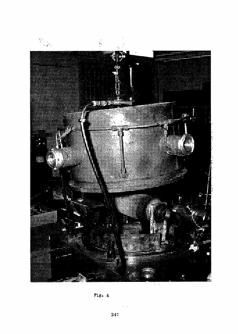
Pig. 4
247
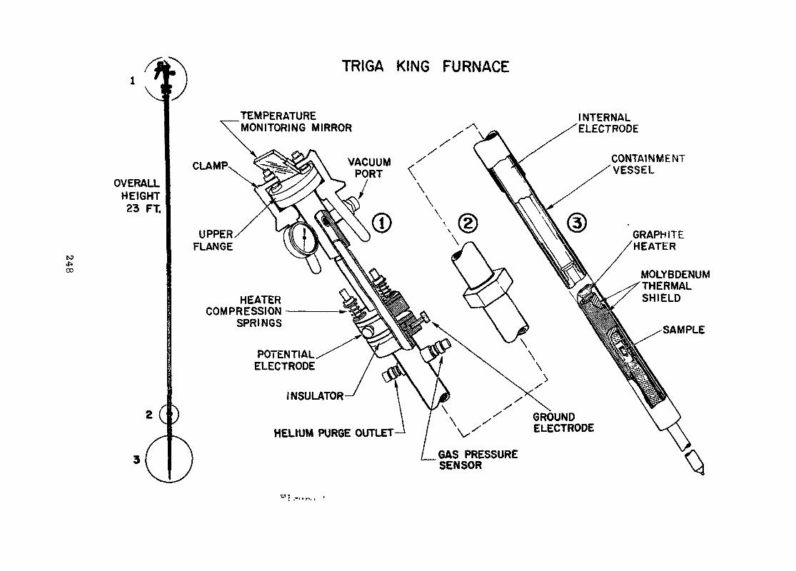
TRIGA KING FURNACE
CO*.CD
OVERALLHEIGHT23 FT.
TEMPERATUREMONITORING MIRROR
CLAMP
UPPERFLANGE
HEATERCOMPRESSION
SPRINGS
INTERNALELECTRODE
POTENTIALELECTRODE
INSULATOR
HELrUM PURGE OUTLET
CONTAINMENTVESSEL
GROUNDELECTRODE
GAS PRESSURESENSOR
GRAPHITEHEATER
MOLYBDENUMTHERMALSHIELD
SAMPLE
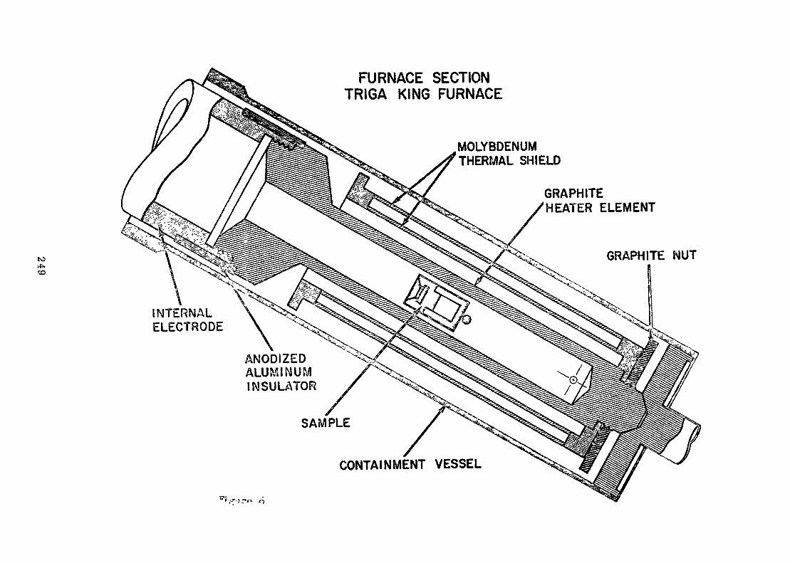
to*..CD
FURNACE SECTIONTRIGA KING FURNACE
INTERNALELECTRODE
ANODIZEDALUMINUMINSULATOR
SAMPLE
MOLYBDENUMTHERMAL SHIELD
GRAPHITE/HEATER ELEMENT
GRAPHITE NUT
CONTAINMENT VESSEL
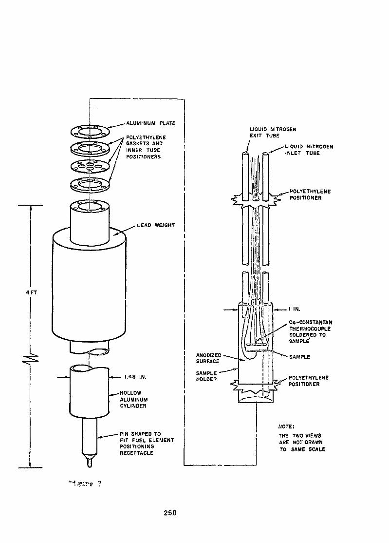
4 FT
ALUMINUM PLATE
POLYETHYLENEGASKETS ANDINNER TUBEPOSITIONERS
¥
LEAD WE/GHT
- 1.48 IN.
-HOLLOWALUMINUMCYLINDER
• PIN SHAPED TOFIT FUEL ELEMENTPOSITIONINGRECEPTACLE
LIQUID NITROGENEXIT TUBE
LIQUID NITROGENINLET TUBE
POLYETHYLENEPOSITIONER
I IN.
Cu-CONSTANTANTHERMOCOUPLESOLDERED TOSAMPLE'
SAMPLE
POLYETHYLENEPOSITIONER
NOTE:
THE TWO VIEWSARE NOT DRAWNTO SAME SCALE
250
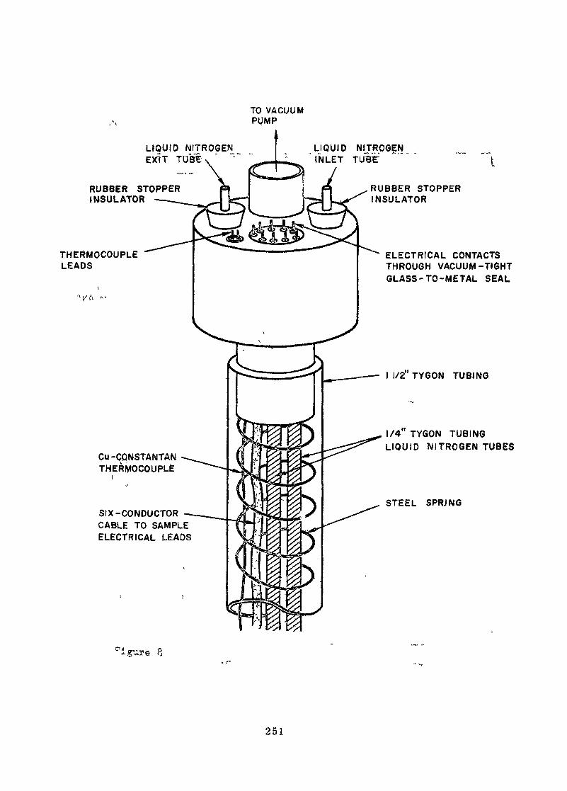
TO VACUUMPUMP
LIQUID NITROGENEXIT TUBE
LIQUID NITROGENINLET TUBF
RUBBER STOPPERINSULATOR
THERMOCOUPLELEADS
Cu-ÇQNSTANTANTHERMOCOUPLE
SIX-CONDUCTORCABLE TO SAMPLEELECTRICAL LEADS
RUBBER STOPPERINSULATOR
ELECTRICAL CONTACTSTHROUGH VACUUM-TIGHTGLASS-TO-METAL SEAL
I I/2"TYGON TUBING
1/4 TYGON TUBINGLIQUID NITROGEN TUBES
STEEL SPRJNG
'igure 8
251
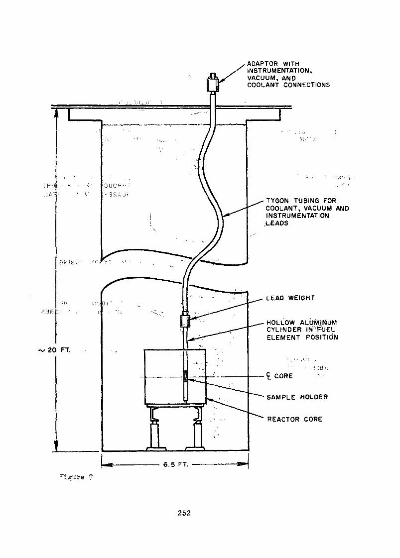
2 3 fi:
ADAPTOR WITHINSTRUMENTATION,VACUUM, ANDCOOLANT CONNECTIONS
•'H-1S8U : - . - ' i ' " , •-.' >
TYGON TUBING FORCOOLANT, VACUUM ANDINSTRUMENTATION.LEADS
LEAD WEIGHT
HOLLOWCYLINDERELEMENT POSITION
;jy AC_ CORE
SAMPLE HOLDER
REACTOR CORE
252
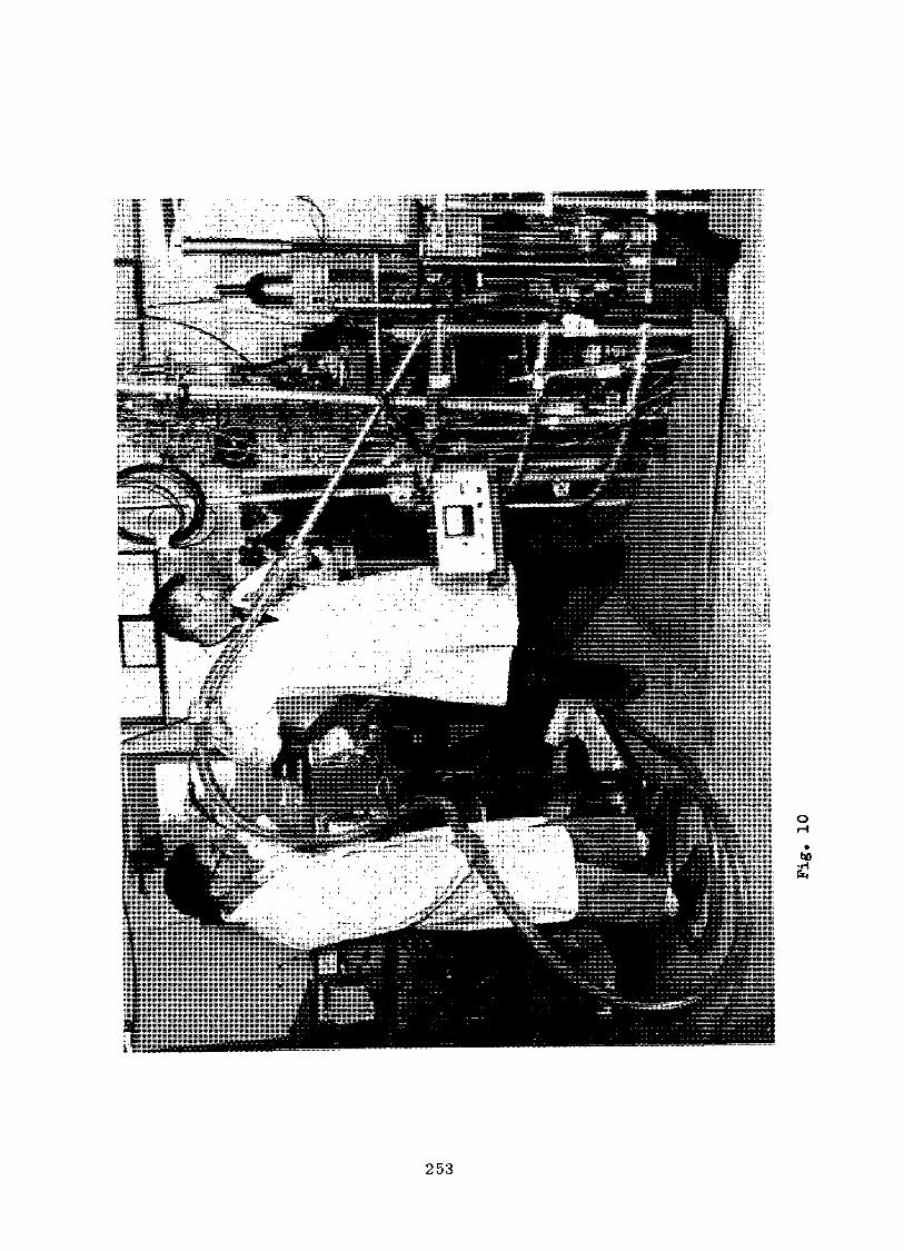
ta£
253
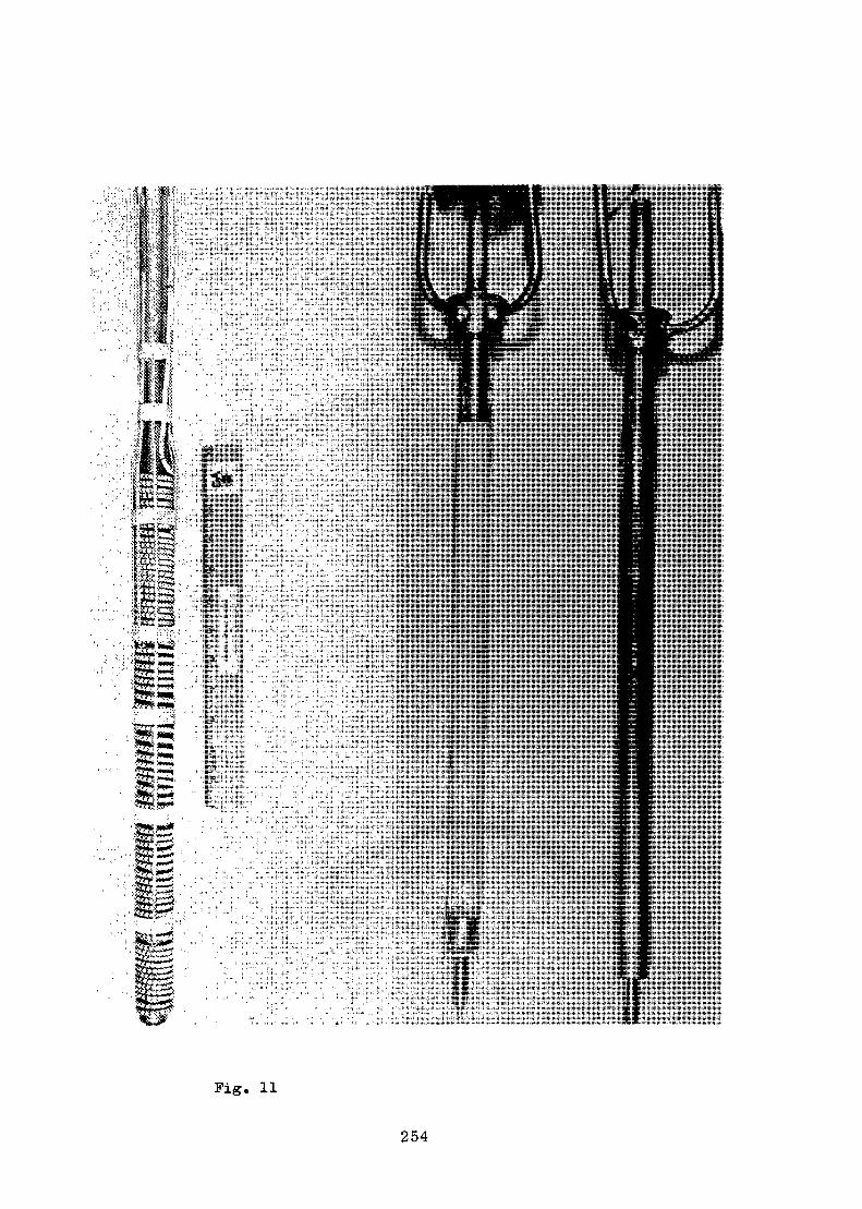
Fig. 11
254
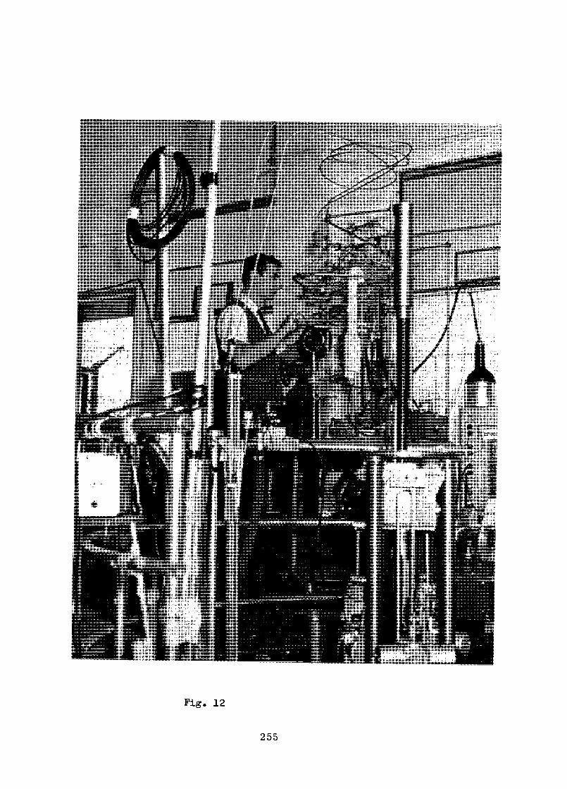
Pig. 12
255

KEFEREKCSS
1. Wang, G, H., "Mounting îfeaàs of University Research Reactor Facilities,"Nuclear News, September 1966.
2. Kelly, F. L., Skovholt, D. J., and Horrio, P. A., "Operator Licensingand Nuclear Plant Simulators," American Power Conference, Chicago,Illinois, Arril 1969.
3. Kaiz, G. H., "The Utilization of Research Roactors in ttie Training ofReactor Operators," Conference on Reactor Operations Experience, SanJuan, Puerto Rico, October 1969.
4. Berger, H., "Applications o? Neutron Radiography," Trans. Am. Nucl. Soc.10, 441 (1967).
5. Watts, H. V., "Research on Neutron Interactions in Matter as Related toImage Formation," USAEG P.e.port ARF-1164-27, Artsour Research Foundation,1962.
6. Bergor, H., and W. J. Mr.Gonnagle, "Progress Report on Neutron Radiography,"USAEG Report ANL-6279, Argorme National Laboratory, December 1960.
7. Thewlis, J., and R. T. P. Derbyshire, "Kcutron Radiography," Brit. £.A-p,p_l' ghy.3. 7.» 345 (155S).
G. Sarger, H., Neutron Radiograp'iy Methods, Cg.gjaMlit.ies_, and Applications,Slcevier Publishing Ccrcp r.y, 1965.
3. Berger, H., P. Dolon, and W. F. Kiklas, "An Iraproved Neutron ImageIntensifier Tube," IMS X££Z?2* SHGl- aSi.- li» 428 (1957).
258
SUMMARY OP THE CURRENT ENGINEERING PROGRAMIN THE 50 MW R2-REACTOR
K. SaltvedtAktiebolaget Atomenergi
Sweden
Abstract
The paper gives a brief description of the irradiation facilitiesand the associated experimental equipment need for engineeringactivities in the H?-reactor. Costs are given for some of themost complex facilities.
The irradiation program for the period 1/7/1970 to 0/6/1971 witha brief description ;of the different expe-j-iments is presented.
The R2-reactpr
The 50 MW (th) material testing reactor R2 is of the familiar MTR type.The reactor core is contained within an aluminium vessel at one end'ofa large open pool, which also serves as a storage for spent fuel elementsand irradiated experiments. At the other end of the pool is an 1 MW (th)open core, convection cooled, movable pool reactor.
Light water is used as core coolant and moderator.
The coolant •.water is circulated through the reactor vessel and it flowsthrough pipes '• and a large delay tank below the reactor hall to an ad3oin-ing plant house containing pumps and heat exchangers cooled with seawater. The water flow rate through the core is 1200 kg/sec. (42,5 cu.ft/sec.)and the inlet temperature is about 60°C (140°F).
Plants for test loops are placed in the area below the reactor hall andis connected to the in-core experiments via tubes passing up through thebiological 'shield around the pool. They terminate in the pool adjacent toconnections in the reactor vessel.
257
The components of the core are arranged in a 10x10 lattice. The normalcore consists of 40 fuel elements, 6 control rods, a number of loops andrigs, all surrounded by a beryllium reflector. The composition of thecore ean be altered to suit the experimental program.
The fuel length is 600 mm (2*). The total dimensions of the fuel elementassemblies are 81,0 by 77,1 mm (3,187"x 3,033") in cross section and924 mm (36,4") long.
The initial fuel content is 250 g U235 per element. The burn-up of thespent fuel is about 50%.
The control rods consists of an upper neutron absorbing section of cad-mium and a lower fuel section. They are moved vertically by drive mech-anisms placed below the reactor vessel.
A summary of the characteristic data for the reactor is given in fig'.. 1.Fig. 2 shows a sketch of the reactor and how the connection of the experi-mental facilities are arranged.
EXPERIMENTAL FACILITIES AND EQUIPMENTS
Fig. 1 shows a lay-out of the experimental possibilities inside the-reactor vessel;
Between 25 and 30 lattice positions are normally utilized for irradi-ation purposes.
The D-0 blanket surrounding the core and Be-reflector on three sidesare penetrated by 10 vertical channels. Some of these are accessiblefrom the outside of the reactor vessel and insulated from the primarywater.
10 horizontal tubes, 6 radial with 15 cm, (6") and 2 with 25 cm (10")diameters plus 2 tangential with 15 cm (6") diameters, penetrate the
14shield and reactor vessel;and give access to high neutron flux (>102neutron/cm • sec.) at the,'core interface. Due to back scattering theD-0 blanket increases the neutron flux in.;the eollimated beam by ap-proximately a factor 3.
258
Rabbit systems .....„:.__.
A three channel hydraulic rabbit system is installed in the Be-positioh K5.
One hydraulic and two pneumatic single shannel systems are placed in theD20-blanket.
The rabbit systems are mainly utilized for isotop production.
All systems are joined to a common pneumatic transport system, leading tothe isotop laboratory outside the reactor building. This arrangementallows the rabbit channels to be remotely charged and discharged from theisotop laboratory.
Thermal column
The reactor is provided with a rather special graphite column, mea-suring 1x1 m (3'x 3') in square, which penetrates the shield and pooland lines up with vessel wall. The column has 160 irradiation positionsand is charged and discharged by means of a rabbit system.
A summary of the characteristics of the different loops in operationat the R2-reactor is given in table 1. The diversity of loops and theauxiliary equipments make it possible to irradiate and test fuel and 'materials under any normal or special operating conditions occurringin existing light water reactors.
All high pressure loops have provisions for water chemistry control andout of pile test sections for comparisional studies.
The high pressure loops have also provisions for withdrawal of the testsample out of the 'active zone of the reactor during operation thus si-mulating power transients or power cykling.
Loop No. 5 is_jhowever,specially equipped for chemistry and corrosionstudies. To be able to simulate the two phase conditions in a BWR thisloop has two different circulation circiuts, one for steam and onefor water. The steam and water are mixed at the inlet of the loop. Allloops except the rabbit system have provisions for different type ofin core instrumentation.
259
Rigs and capsules
A great variety of; different ,rigs and capsules are developed for dif-ferent purposes. The out of pile auxiliary equipments are standardizedas fare as possible and fixed installation is made for connections of10 rigs or capsules at the same time.
Connections are made to central gas supply, to vacuum and off-gas systemand to control room alarm panel and computer.
Some of the more advanced rigs and capsules shall be described here.
The standard rigs are made for operation at constant temperature atalt. 60°C, 220-350°C and 550-700°C. Loop capsules are operating at285°C and 325°C respectively.
Several different rigs are developed where stressed specimens can beirradiated under constant load. Unstressed specimens irradiated in thesame rig. After irradiation the specimens can be tested further to rup-ture under the same stress and temperature conditions in remotely opera-ted out of pile creep testers.
Fig. 3 shows the arrangement of one type of this rigs. The specimens aremounted on ring-shaped holders by means of flexible joints, each ringcarrying three stressed and three unstressed specimens. The load is ap-plied by a spring via a pivot, and the stress is measured by strain gauges.There are three specimens holders in each rig, which gives nine stressed«and nine unstressed specimens per rig.
Canning tubes are subjected to pressure cykling in a rig for studies ofthe irradiation effects on in-pile fatigue. There are several identicalrig thimbles each containing a furnace and a test assembly. Each assemblyconsists of the specimen which is a piece of the actual canning tube,
260

surrounded by a thick walled outer tube and with an insert in the middle.The ends of the assembly (outer tube, test specimen and insert) are seal-welded together. The two gaps, between the test specimen oh one side andouter tube or insert on the other, can each be pressurized by gas viasmall bore tubes. The amount of strain in the test specimen is dependenton the size of the gaps.
Another type of rig is designed for in-pile plastic fatigue tests attemperatures between 230°C and 650°C and operates by reversed bendingof strips. The principle of this rig is shown in fig. 4.The test specimen is loaded axially and bend over a pair of jaws bytwisting the tube shaped support shaft. The whole assembly is surroundedby a heater.
Fig. 5 shows on in-pile autoclave used for stress-corrosion studies.The corrosive medium is pressurized water or steam with specific con-taminants added. Maximum temperatures and pressures are 650°C and 100bars respectively.
Water is drawn from a container outside the reactor and pumped by anair piston .pump at a rate of 20 kg/h into the rig, where it is evaporatedby gamma heating. After passing both outside and inside the tube shapedtest specimen the steam meets the incoming medium in a regenerative heatexchanger and passes via an adjustable restriction out of the reactorthrough a heat exchanger into the waste line.
Stresses of the test specimen (e.g. piece of the actual canning tube) arecurried out by over-pressure of the medium.IRRADIATION PROGRAM
Fig. 6 shows a schedule for the utilization of the engineering facili-ties in the period 1.7 1970 to 30.6 1971.
The isotopproduction and the experiments on basic nuclear physics arenot included.
In the following a brief description of the subjects for the differentexperiments is given
261
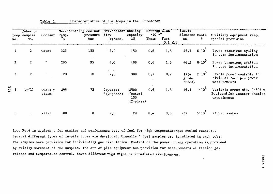
Table 1. Characteristics
Tubes or Max. operating coolantLoop samples Coolant Temp.No. No. °C
1 2 water 325
2 2 " 2 8 5
3 2 " 1 2 0-
o> 5 1+(1) water + 295-CO steam
pressurebar
155~>
95
10
75
of the loops in the R2-reactor
Max. coolant Cooling Neutron, flux Sampleflow
kg/sec.
"4,0
6,O-
2,5
2 (water)4 (2-phase)
capacity -10 * diameter CostskW Therm
150 0,6
400 0,6
300 0,7
2500 0,6(water)150(2-phase)
Fast ;mm $>0,1 MeV
1,5 46,5 6-105
1,5 46;5 8-105
0,7 17(4 2-105guidetubes)
1,5 46,5 1-106
Auxiliary equipment resp.special provision
Power transient cyklingIn core instrumentation
Power transient cyklingIn core instrumentationSample power control. In-dividual fuel pin powermeasurementsVariable steam mix. 0-30% wEquipped for reactor chemistexperiments
water 100 2,0 20 0,4 0,3 -35 5-10 Rabbit system
Loop No.4 is equipment for studies and performance test of fuel for high temperature-gas cooled reactors.Several different types of in-pile tubes are developed. Ursually 4 fuel samples are irradiated in each tube.The samples have provision for individually gas circulation. Control of the power during operation is. providedby axially movement of the samples. The out of pile equipment has provision for measurements of fission gasrelease and temperature control. Seven different rigs might be irradiated simultaneous.
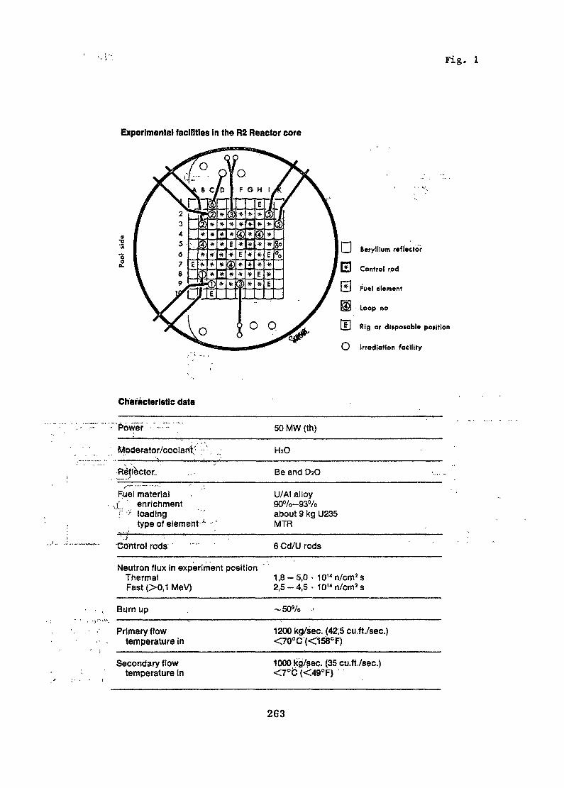
Fig. 1
Experimental facilities in the R2 Reactor core
o£
I_I Beryllium reflector
*J Control rod
Fuel element
Loop no
U Rig or dlsposoble poiition
O Irradiation facility
Characteristic data
Power
Moderator/coo!ani'; ;• '-,
Reflector.
Fuel materialv( " enrichmentf •? loading
type of element••*
Control rods
50 MW (th)
HsO
Be and DaO
U/AI alloy90%-93%about 9 kg U235MTR
6 Cd/U rods
Neutron flux in experiment positionThermalFast (>0,1 MeV)
1,8-5,0 • 10Mn/cm2s2,5-4,5 • 1014n/cmss
Burn up -50%
Primary flowtemperature in
1200 kg/sec. (42,5 cu.ft./sec.)<70°C (<158CF)
Secondary flowtemperature tn
1000 kg/sec. (35 cu.ft./sec.)<7°<J (<49°F)
263
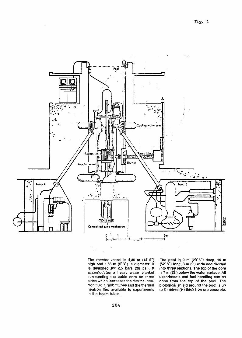
Fig. 2
UI.MIfefliktbn
Control rod drive mechanism
The reactor vessel is 4,46 m (14'6")high and 1,58 m (5'3") in diameter. Itis designed .for 2,5 bars (36 psi). Itaccomodates a heavy water blanketsurrounding the cubic core on threesides which increases the thermal neu-tron flux in rabbit tubes and the thermalneutron flux available to experimentsin the beam tubes.
The pool Is. 9 m (29' 6") deep, 16 m(52' 6") long, 3 m (9') wide and dividedinto three sections. The top of the coreis 7 m (23').below the water surface. Allexperiments and fuel handling can bedone from the top of the pool. Thebiological shield around the poof is upto 3 metres (9') thick Iron ore concrete.
264
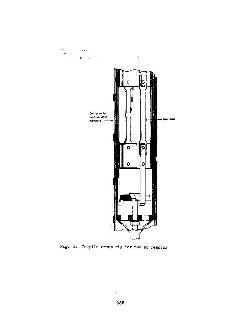
Container lorneutron dosemonitors —— specimen
Fig, 3. In-pile creep rig for the R2 reactor
265
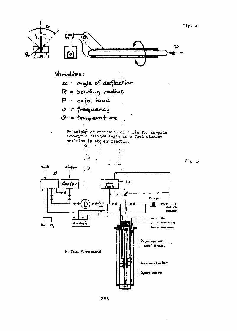
Fig. 4
V/oriables :OC ^
P « axial looci
of def/ection
Principle of operation of, a rig for in-pilelow-eye le fatigue tels t s in a fuel elementposition-in the-RS-reaetor.
' ' '
Fig. 5
If 1£««{•»•> EXP--
t' •- h1 ;,. . A';,",-• ; *
He
!» ————F.'H-er-
266
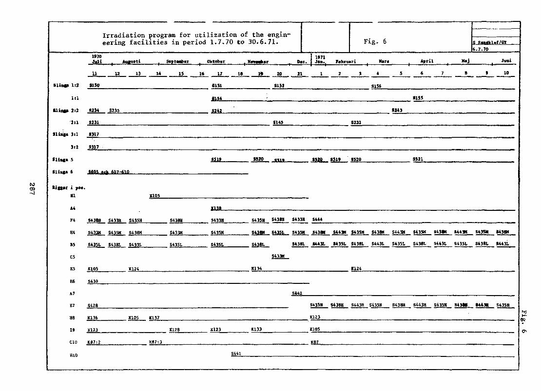
N)
Irradiation program for utilization of the engin-eering facilities in period 1.7.70 to 30.6.71.
Slit*» 1:2
iti
•ling» 2:2
Slim* 3tl
3c2
•lias* 5
Slin8« 6
>itt«r i pot.81
A4
F4
B4
B5
C5
ES
H6
A7
E7
H8
19
CIO
H10
1970 j 1971Juli Auftutti S*ptmb*r Ok(ob«r K»M«t«r D«c, I J*n.
11 12 13 14 IS U 17 18 » 20 21 1
3150 6151 S152
B154
S234 S235 S242
S231 S145
5317
S317
SW J320 M1, §529
SCOS ptK &&7-610
X105
1138
S438B S433H S435H S438U S433H S435H S438H S433H S444
S433K S43SM S438M S433H S43SK S438M S4351 S43SM S43«
S435L S43BL S433t S43SL S435L S438L S438L S443L
S433M
K10S K124 XI 34
S439
S442
S428 S435H
K136 K105 X137 K123
K123 C128 K123 K133 KIDS
K87:2 K87-.3 K87
S441
Fig. 6 S Sindkl.f/CT6.7.70
Fcbnuri j Har» ( April ( H»j ^ Junl
2 3 4 5 6 7 8 » 1 0
S156
8155
(143
S232
SS1» 8520 $521
S443M S435M S438H S443M S433K S438K S443M 3433* S438H
M35L S438L S443L S435L S438I, S443L S435L S438L S443L
K124
S438H S443H S43SH S438B S443H S43SH S43M 8443H S435HhdH-
OQ•
O>
Reactor fuel and material development
1. Measurements of heat conductivity and fission gas release in U0_-fuel at high temperatures and with increasing burn up. (Exp-R2-S150and Exp-R2-S232>.
2. Studies of the behaviour of fuel rods with defect cladding at con-tinued irradiation. (Exp-R2-S150) .
3. Performance test of U0«-fuel pins with variation of operational conditions and burn up. (Exp-R2-317) .
4* Performance test of (U, Pu)0--fuel pins at different power ratings, -S608, -S609, -S610).
5» Performance test of fuel for high temperature gas cooled reactorsat different operation conditions. (Exp-R2-S428, -S433, -S435, -S438,-S439, -S441, -S442, -S443, -S444).
6. Performance test of fuel pins of UNC at high power ratings. (Exp-R2-K128) .
7. Studies of mechanical interacion between fuel and cladding material.(Exp-R2-S605) .
8. Studies of the hydrogenization of cladding material due to waterimpurities in the fuel and surface treatment of the cladding.(Exp-R2-S231) .
9. Fundamental studies of the influence of irradiation on the creep-behaviour of cladding and construction materials. (Exp-R2-S151, -S152,-S153, -S156, -S234, -S235, -S236).
10. Fundamental studies of He-production in construction material andits influence on the mechanical properties (Exp-R2-Sl37) . •>
11. Irradiation of construction materials in use in Swedish reactors.for control test of mechanical properties. (Exp-R2-K105) .
268 """
12. Fundamental studies of changes in the mechanical properties ofcladding material influenced of irradiation and at high temperatures.(Exp-R2-K134, -K136, -K138).
Reactor chemistry
1. Studies of radiochemical reactions and corrosion processes in BWR-conditions. (Exp-R2-S519, -S521).
2. Studies of the influence on hydrogenization and corrosion of canningmaterial from contamination with fissile material. (Exp-R2-S154).
3. Radiochemical analyses of fission product release from HTGR-fu.els.(Exp-R2-S428, -S433, -S435, -S438, -S439, -S441, -S442, -S443, -S444)
4. Fundamental corrosion studies with variation of water chemistry andoperational conditions. (Exp-R2-K87).
Questions and/or Comments
One of the emerging subjects here is that loops are a key pointand I think we must consider that developing countries have only gotlimited financial resources. The experience of nil who have built andused loops is that loops are expensive, very expensive. They are verytime consuming, therefore results from them cannot be obtained quickly.They need a considerable number of staff and g lot of experience to bedesigned, built and operated. And before you start designing a loopyou should seriously consider what can be done for the more simpleexperiments in the form of capsules. We in the U.K. are not against,loops but we believe that loops have only a particular place in aprogramme. We believe that we can get a lot of useful information fromsimpler experiments and combine this with a minimum expenditure onloops. The general discussion would bring out the point that loops have
269
a place taut this has got -^o^ha^e very serious consideration of all thematters connected with them before embarking on it because of theexpense time scale and staff involved.
Are these experiments and projects in reactor fuel and materialdevelopment performed on behalf of the nuclear power industry ?
The research programme is, prepared by a, cojmritt.e with representativesfrom the industry and from the Government.
you elaborate on the point that you have made in your presentationi.e. a loop cannot do full scale tests. 'We in Canada feel that in apressure tube reactor one of the virtues is that in fact loops can dothe full scale test exactly in the right environment for the final powerreactor. Did you intend to confine your rema.rk to a certain type of reactor?
That is right. My remarks are concerning it. The most useful typesof reactors' are MTH reactors, for instar.ee.> I would say that reactorswhere you can test full scale reactors should be considered as prototypereactors rather than research reactors.
270
MANPOWER REQUIREMENTS,AND ENGINEERING PROGRAMS
USING RESBRACH REACTORS IN CONJUNCTIONWITH NUCLEAR POWER REACTOR PROCUREMENT
tyH. H. Kleijn
Interuniversitair Reactor InstituutD«lft, Netherlands
Abstract
The paper discusses the manpower reauirements in governmentalagencies, utilities and industry as well as the function of nationalresearch establishments and universities in relation to the pro-curement and operation of nuclear power plants in a developingcountry. Further, various types of general purposes researchreactors are analysed in terms of their potential for training andresearch programmes. Cost figures of the operation of thesereaotors are given. Following a few remarks on the required researchenvironment infrastructure a number of research projects are proposed.General recommendations on the subject matter to developing countriesclose the paper.
7. Introduction
Prior to making a few remarks on research reactors and possible engineeringprograms to be executed with these facilities I would like to commenton the point of man power requirements in developing countries for thenuclear power era. These comments are based on experience in my owncountry and observations abroad.
Before writing down this contribution I have pictured a prototypicalaverage sized developing country, presently based on agriculture andasked myself the question : how would I go about getting thingsorganized. Well, here are some of my considerations :
271

First one should distinguish between a country that - for the time being -will not procure a nuclear power plant and a country that is consideringbuying in the near future.
Because of the role that nuclear energy matters play in the world todayI am convinced, that even a country that is not planning to go nuclearmust have a small core of professional nuclear engineers. They shouldassist the government in decision making policies in regard to inter-national agreements, licensing, public health, energy resources, etc.It is also this group of people that should get involved in the initialplanning stage of a nuclear power plant. When these specialists have toupdate their knowledge only from books or journals their expertisebecome quickly obsolete. Therefore it seems necessary that the individualsare - from time to time - engaged in active projects and whenever possiblein research activities, either in the home country or abroad. It has .beenrealized, that in cases where people from developing countries have beensent abroad for further education it led to their emigration and thisof cpurs,e is not the idea. Training facilities in the country seem there-fore advisable.
When one is considering a country that plans to go nuclear, it can be . .assumed that the following task is or has been performed by a govern-mental agency in cooperation with a utility team and possible outsideconsultants:
A power requirement plan for the future (near and long term) has beencrystalized, geared to the general development plan, and optimized interms of production unit size, transport and distribution cost.Studies are or have been made to determine the cheapest and mostreliable production system (over thé plant life time) for the countryproper, taking"into account a certain reserve production capacity andguaranties for fuel supply. Other parameters influencing this study"include social-economical matters', environmental pollution, man power,financing and local and international politics, obviously thé'outcomeof this task implies that nuclear power looks attractive. In this phaseof the programming there has been little need for nuclear expertise.
272

Continuing with the country that wants to go nuclear, now the role ofthe following functional components have to be considered: the utilities,the industry, a national reactor research centre, and the universities.
However, before discussing this role aspect I would like to look at thepossible reactor. Taking into consideration Little's report oncompetition in the nuclear power supply industry it is clear that thereactor will be bought from & reliable xoreign supplier. This reactorwill naturally be of the proven type. Therefore fast reactors can, forthe time being, be left out of the picture. Looking at thermal reactorsone can distinguish between light and heavy water reactors (includingmixed moderator and SGHWR systems), the AGR and in the near future HTGRsystems. American and European utilities have favoured light waterreactors and undoubtedly the nuclear steam supply system industry hasmost experience with this type. Until now developing countries weresomewhat reluctant to consider systems working on enriched fuel. It maywell be that this philosophy changes when enrichment services becomeavailable in Europe. There remains the problem of reprocessing
An economic evaluation, taking transport cost into account should indicatewhether a once through fuel cycle or reprocessing is to be preferred.
Local reprocessing should not be considered as long as just a fewreactors are to be served. Another factor that will play an importantrole in the type-selection is the unit size of the required system.For the time being only small and medium size power reactors can be
» A.D. Little, Competition in the nuclear power supply industry,x - l (1968).Foratom, The Future of Reprocessing in Europe (1970).
273

•Mforeseen, (upto 400 MWe) ,. This again is an argument in the directionof selecting light water .reactors which also have the advantage oflower capital' cost important when liquidity is scarce. I dwelled onthis selection problem of reactors because it affects the directionin which people are to be trained initially. Later on, when the unitsize increases along with the power requirements other systems mustbe considered as well.
Let us now turn to the utility with little or no nuclear experience,that is planning, the acquisition of a power reactor. At this momentI want to quote William Webster of New England's Electric in the USA.In a speech to a group of European utility and nuclear executives
5C3fpresented at Oak Ridge in 1968 he gave the following advice :
1. Select a few competent, seasoned engineers very early and starttraining them by sending them out for broader, quicker indoctrination,At the same time, select one key man who throughout the job willhave responsibility and authority. This nucleus should be assembledfrom within the company rather than by outside hiring.
2. Get a few:competent consultants in specialized fields and, ifpossible, tie in with some nearby technical university.
3. Select an architect-engineer who can help you greatly, not onlyafter commitments are made, but also in the early stages of plann-ing and selection. In choosing the a-e, look not just at his priorexperience but also at his work load, the key individuals he willassign to the job and the ability of these people to work with yourorganization.
4. Don't write detailed specifications for the nuclear steam supply, butdecide on approximate size and probable scope of supply you expectfrom the manufacturer. Following this, hold discussions with three tosix possible suppliers and find out what they propose to offer. Atthis point, check the suppliers' work load and determine if they cansupply your plant on the desired schedule.
IAEA, Small and Medium Size Power Reactors (1968)Nucleonics Week, November 21 (1968)In The Netherlands COMPRIMO NV is delivering these services.
274

5. Now you'll need all the help you can get from your a-e. There willbe many differences in the proposals between manufacturers, even forthe same type of reactor, so considerable engineering effort is neededto put the bids on a comparable basis (what is included in the offerand what not). Nail down all details of scope of supply and system designbefore you award the contract. Above all, do not commit the NSS? untilyou have negotiated arrangements for fuel supply. Shoot for a first-corecommitment only and insist on complete design details so that reloadregions can be purchased by competitive bidding. Furthermore, it is ,advisable to obtain options for one or more reload regions, so as to.bein a completely flexible position. Finally, if possible, arrange yqurschedule so that you can. tolerate delays in licensing, financing, siteselections, etc.
6. As soon as possible after making a commitment, freeze as many designdetails as you can. Do not allow scientists and physicists to lead youdown the garden path - sell you minor improvements or turn the projectinto an r&d program. Aim for a compact construction schedule and gearprogress payments to actual work done. In other words, do not financethe manufacturer your money.
7. It's never too early to start planning the plant operating staff. Thesuperintendent and three to four key men on his staff should be pickedtwo to three years before startup and sent to other installations;,preferable "sister" plants, for training. Yankee organized a trainingschool at the site of its two completed projects about a year beforestartup for the top 30-35 plant staffers, Instructors were drawn fromthe Yankee staff, consultants and engineers from the vendors and a-e's.
8. In the final stages of construction and after the plant has gone intooperation, it is important to shield the operating staff from swarmsof visitors and other public-relations activities and problems havingto do with regulation and licensing.
From Webster's remarks one can see that he depends heavily on anarchitect-engineer. These services are only required temporarily andcan be obtained from abroad. As a consequence the nuclear trained manpower at the utility can be limited. In the US many utilities makeuse of consultants for fuel cycle analyses, while in Europe the
TJuclear Steam Supply System
275

utilities, most of which., a,re nationalized^ perform their ,own fuel /••• •cycle, management. The.lat.ter is qf ,course .only attractive when thereis a number of reactors to serve. It seems that gradually the USutilities plan, to fallow the European practice. ..As, .an example it maybe mentioned that from the two power stations in The Netherlands the
•• .,••'••- , """-.l. S J.'l .„..!!' . '• ' ' ,
operating 50 MWe BWTR is, and the 400 MWe PWR, which is under..con-struction, will.be staffed with 65-70 people. Excep.ç, for the rshif t -•-•;•,personal only two professional, people for management are required . >-.i -, rper plant. Here the .fuel cycle management is performed by .-a. central; .•.•utility office. Thus, the requirements for nuclear .trained professional-.!..
:.:, --V .J\it-;-. i ' . • - .-.\ ':•.!-• ' ' " " - .
man power are rather small. There remains the education of .technician's ?Ji.e. shift personel, health physics and chemistry assistants-*.- About 2&-to-30 nuclear trained people are required per ppw.er piant. A uniyersityc-V,nuclear centre may initially do some good work in. this area.- -Later ,,. if, ••'ih.,_w a'> ;-.-. $ t:*. ' . • •• •• ; " • " ' ' ' ", "'; ' " ' • • ! • ; . •the utility staff will be able to hancHe ipersonel training. ,-. -. -> ~H<.--.-•f^>f^t •-;-. : " • - , " ' " " ' ' " " - " • • • • • - - ^ ° - - - • • ;
Let me now say a few words 4.bout the ro^e of -the industry^ j^r^_.. >-i.iij r: ' if- '.' ., ~ -' ' '' "
the local industry will not be able to offer the.,complete plant*,.neither will it be able to make components.like pressure.vessels» etc.AT • "' •-.-•'•• -'' , '•* • • ' " . , >Balance of payment considerations, however>f,require that -the..country'sindustry parc icipat:es..asi much as possible in.the delivering ;of -;.• .-accessory components. These will be made according to specificationsj - •-- . :. - .. •.'• , -- -'- • '-and only require superficial nuclear knowledge. , •> a
• .I'' "*'"•'' .' '' "' '' *• H
,, _ -, .-. ' ; y " '';- •• v'
I also considered the function of a national nuclear research, centré;* T 'To my opinion, a country that has no industrial activitiesjsj,equ'i,.r.ittg"v-,•';'detailed nuclear knowledge, should n,ot erect a typical.nualefXP recentre with reactor facilities and,.all .that, .You may. be wellwith the fact that there exists a significant surplus of professional,nuclear expertise in the US and in Europe. The need for these peoplehas been gross,JLy .overe'stimate'dvGn .one* hand, while on 'the*.•ether nuclear-reactors have come -itp-.;,-iQomnje;r:ci l5 staitus .'.diminishing the- number"of.-..:•developme/ntii, jgrpj çpfes -ieajiing ,:-t-6 layr?ofeE.,,of :> employees: General r-esearchin engineering ;is pMphf metre/^watdingv >• „ '. < . n; ; *n -w^ , f- •.•?!• ;•
It is no secret that executives in the western countries are presentlyfaced with the problem of what to do with the staff of these centresespecially in a period of restricted budgets.
276

I see an important role for the universities. I believe that it issufficient but highly necessary that one of the universitiesin a developing country offers a program in nuclear engineering . Thisdepartment which should cover the range from engineering to physics canserve as a backbone for the nuclear expertise. It must have closecooperation with the government, the industry and the utilities. Sucha centre has the advantage of through streaming of personal (students).It can offer post graduate training but can also assist in educatingpeople of the technicians level. It can be limited in size and budget.It can have easy access to other disciplines. There is not the seriousquestion of career planning and further there is not so much the problemof national centres where people are eager to develop their own reactorconcept. We, at Delft, are at all times willing to offer advice forestablishing a university research centre.
The main message of this introduction is: do not train too many nuclearpeople. For 90% reactors are based on conventional engineering and ifone trains too many nuclear experts one is bound to get a lot offrustated people.
2. Research veactovs
Nuclear power reactors have been developed to the point where only highlysophisticated experiments requiring specialized research equipment (i.e.LINAC's, Fast Flux Test Facility, Loss of Flow Test) will solve stillexisting essential problems. This is particularly true for data lackingin thermohydraulics, fuel behaviour ant. in safety area. Considering theamount of money that is involved in realizing this research I do notbelieve that participating in reactor development as such is a toppriority item for developing countries.
The research reactors, which now exist or those which are planned inthese countries should be used for general training purposes in areasof physics and to limited degree in engineering. That some research iscarried out which has been performed elsewhere is not bad because
It is not so, that students trained in this discipline necessarilyselect their career in the nuclear profession.
277

people have to become familiar with experimental techniques. Further,there still exists a vast number of small problems to be solved, thathave been neglected by the big laboratories and industries, eitherbecause these problems are commercially not attractive or they havesimply not been recognized as such. It is strongly recommended thatthis experimental work be supported by theory. The use of digitalcomputers in the course of this work is an absolute necessity.
Research reactors can roughly be divided in four catagories:
a. critical experimentsBy nature critical experiments contain a critical mass and operationalerrors may lead to a supercritical reactor. Therefore adequate safetymeasures in terms of instrumentation, control devices and shieldingare required. This fact makes such a system just as expensive as aresearch reactor working at some power level. The use of criticalfacilities is limited to studies in reactor physics/ which may beperformed in great detail. Because of criticality, skilled supervisorypersonel is required. The low power level limits the range ofapplicability of a critical experiment. These facilities are almostexclusively used in a reactor development program.
ï, low level research reactorsLow level research reactors such as Argonaut systems, with fluxlevels up 1011 neutrons/cm2 .sec can advantageously be used forstudies in the areas of reactor and nuclear physics, instrumenta-tion, and chemistry (activation analysis). Because of the fluxlevel these reactors are not suitable for attacking problemspertaining to fuel^ material or thermo-hydraulic engineering, i.e.engineering research.
•intermediate level research reactorsReactors, with steady state power levels upto 5 MWth, correspondingwith fluxes on the order of 1013 neutrons/,cm2 .sec can be consideredas intermediate level research reactors (pool type reactors, heavywater and graphite moderated reactors). These reactors can primarilybe used as neutron sources for experiments in reactor physics,neutron physics, nuclear physics, chemistry and biology. Due to the
278

power level, however, these reactors have limited possibilities forengineering type experiments. However, by using such a reactor oneobtains a lot of operational experience, not only concerning thereactor itself, but all the associated problems such as in healthphysics, instrumentation, nuclear electronics and équipaient design.Further, it should be realised, that the level of the radioactivematerials within the laboratory increases with the reactor powerlevel.
a. high level veseaxcih reactorsHigh level research reactors (flux > Î01* n/cm2.coc) are less suitablefor studies in reactor physics, but excellent for beam experiments(neutron and nuclear physics), engineering studies and fuel develop-ment. However, these reactors require frequant refuelling, with allassociated problems of fuel transport and reprocessing.
Cparating the first thres categories of reactors is in general no problem.Opération of the high level research reactors is very costly.Getting research reactors leaded with experiments has proven to be aconstant headache. The cost of experiments increases with the reactornov.-3r level. To give an example, tho annual operational expenses ofthe 45 MIV th HPR at Petton, the Netherlands, amounts to about $2.6 millionincluding personnel and fuel cycle cost.
Critical experiments and high level research reactors are onlyappropriate for industries involved in coro design respectively fornational research centres, r-r'-iile low ar 1 intermediate levl systemscan be used advantageously ty university centres, ior the firstcatagory the research has - by nature - to be more applied while inthe latter the research can be more fundamental and academic. Thisitrplies, that with the present state of reactor development andfinancial resources, it is much rare difficult to define anappropriate research progretn for a national centre than for a university.
When a distinction is made in physics oriented and engineering typeresearch in connection with nuclear reactors the latter is moredifficult to perform in developing countries. Expertise in thisarea should be obtained by sending qualified people abroad. The
279
acceptable facilities in the home country must then be used forgeneral training in chemistry, physics and r,eactor operation.
It has been our experience at Delft, where we operate a 2 MW poolreactor, that in the long run experiments of different disciplinespose different requirements to the reactor in terms of power level,operation time, accessibility of the core, neutron spectrum, etc.This means that the various research programs are sort of limitinganother. Therefore it is very necessary, that the research to becarried out with a reactor is carefully planned before procurement.To conclude this section I would like to present a few datapertaining to the reactor at Delft and a low level research reactoroperated by the Eindhoven University of Technology.
a. Interwiveraity Reactor Institute (IRI)IRI, at Delft, The Netherlands, is a university nuclear centre, atwhich research is being performed in the areas of reactor physics,neutron physics, radiation chemistry and radiochemical analysis.The principal facility of the institute is a 2 MW pool reactorusing 90% enriched MTR type fuel elements. This reactor is heavilyloaded with experiments. It is operated continuously during weekdays, requiring an operating staff of 17 persons. In the domain ofreactor physics experiments are going on in fast and thermal neutronspectroscopy and on temperature dependent resonance integrals, ofcoated particle fuels. Very broadly the aim of this work is toverify existing calculation methods and wherever possible to obtainimprovements. Therefore the experimental work is strongly supportedby code development work. Thus, work in the reactor developmentregion is more in the area of physics than in engineering. Thereason why is that the available neutron flux level (average thermalflux ^2xl013 ncm~is~1) is too low to observe significant phenomenaof engineering nature within a reasonable period of time.
Establishing the IRI-centre, which was constructed between 1958 and1962, costed $1.4 million for the reactor and $2.0 million for theadjacent laboratory buildings. Initial laboratory equipment amountedto $0.8 million. In 1965 the laboratory was staffed with some 100persons and then the annual operating expenses were $1.16 million.
280
Now, in 1970, the number of employees is 152 and the expenses haveincreased to $1.72 million (including inflation). Of this amount50% to 60% is required for personel expenses. It is interesting tonote that the operational cost of this institute per person areabout the same as that of the national reactor centre RON, also interms of personel expenses.
b. The ATHENE-veaator
The ATHENE-reactor is a low level research reactor of the EindhovenUniversity of Technology. The reactor is a modified Argonaut reactorsystem consisting of two rectangular core sections fueled with MTRtype fuel elements moderated by water. The two core sections areseparated from another by a removable graphite block. Concreteprovides the required shielding. The reactor and adjacent laboratorywere built between 1966 and 1968 for a total amount of $1.4 million.At present the operational staff consists of 12 people and the annual reactoroperating expenses are about $40,000,-, not including salaries.
This system is particularly suitable for studies in reactor physicsboth core physics and shielding (due to a special facility) andfurther for activation analysis.
One of our IRI staff members is using the reactor for an experimentin regard to Doppler phenomena in fast neutron spectra.
5. Research programs
After the remarks on man power and research reactors in general, I wouldlike to get more specific and make a few suggestions for experimentalprograms to be executed with research reactors. First, however, I wantto mention two general points.
1. Many experiments which have been performed to appraise quickly thephysics or engineering characteristics of certain reactor componentshave been complex and the combined effects of many variables (oftennot controlled or even known) have confused the interpretation of theresults. The confusion leads to errors in predicting performance.
281

Therefore it is recommended that many-parameter problems are separatedas much as possible in single-parameter problems so that each of thecontributing phenomena can be properly analyzed and accounted for.
2. Smooth execution of research programs depends heavily on the infra-structure of the laboratory. It is necessary that the staff has accessto qualified mechanical and electronical work shops and in particularfor chemistry research glass-blowers are essential. Also well-equippedlibrary facilities must be at hand. Further it is a must, to have afairly sized digital computer (fast memory at least 30 K) at onesdisposal.
As indicated low level research reactors are typically suitable for reactorphysics experiments and activation analysis. In the area of reactor physicsinteresting experiments can be done on:
a. reactivity effects caused by heterogeneities, for instance coolant voids,control elements and fuel element geometries. These experiments requirea thorough knowledge of the spatial neutron spectrum dependence.
b. under-moderated lattices. This work should be executed in bothmacroscopic and microscopic fashion. Substitution techniques can beused advantageously.
c. shielding. In general experimental shielding research has not beenperformed to a great extent. Whereas a lot of money is involved inreactor shields it is justified to pay more attention to shieldoptimization. Neutron and gamma-ray spectrum measurements in shieldmock-ups can provide valuable data.
It is our experience at Delft, that between $40,000.- and $60,000.-have to be invested in equipment for these type of experiments.
For reactor chemistry as such, low level research reactors are not verypractical. However, in developing countries these systems may be usedfor soil and mineral research using activation analysis. Also researchon rare earths is presently of great interest. Further these reactorscan be used for fabrication of short lived tracers, which forces theresearch people to study various separation and analytical techniques.In addition, low level research reactors can be used in the area ofinstrument development for both health- and reactor physics purppses.
282

In particular one may think of various types of detectors which can beused for spectrum measurements. In this regard work on solid statedevices is highly interesting.
Intermediate and high level research reactors can be used for fuel,material and thermo-hydraulic research. A lot of data are available onoxide fuels and to a certain degree on carbide fuels. However, many dataare lacking on fuels based on nitrides, sulphides, phosphiCss and cermetswhich may be promising for future reactors. Of particular interest isthe thermal conductivity as a function of temperature. In addition,fission product distribution inside these fuels, the fuel swellingbehaviour as well as the attainable burnup are important. In connectionwith this item also fuel-cladding compatibility studies are recommended.These experiments, if properly designed, can be performed with relatively
OT. capsu.lesimple loop/experiments. In the area of materials one may further lookat the behaviour of shielding materials under irradiation. Further, thedevelopment of in-core instrumentation for the determination of temperatureand flow distribution in fuel bundles will provide valuable engineeringknowledge with regard to reactors. These devices can be incorporated ininstrumented fuel assemblies. Another subject which requires furtherinvestigation is the cladding circumferential temperature distributionof light water reactor fuel rods. Turning now to reactor chemistry oneshould realize that the chemistry aspects of a reactor are more of atechnological-material nature» Experiments can be performed on temperaturedependent corrosion experiments of various cladding and constructionmaterials. Further research in regard to mass transport, carbonization,nitriting and hydriding of metals is also of interest. Finally one maylook at the solubility of gases and neutron poisons as a function oftemperature in water.
Most of the subjects which I have mentioned above assume that theexperimentalists are familiar with the techniques that have now becomestandard. It is clear that research experience must be obtained fromsimple experiments..Therefore initially repeating work that has beenperformed previously elsewhere is adviced so that the results caneasily be verified and one obtains confidence in the working methods.
283

4 » Conclus!onIn conclusion I would like to summarize the main points of rfiy'con-siderations as follows :1. whether or not a country is planning to purchase a nuclear power plant,
its government need a small core of senior professional nuclear en-gineers (about 5 people with broad experience in applied and to someextent in fundamental nuclear sciences) to consult in policy makingprocesses.
2. the nuclear trained professional man power at utilities can berelatively small (2 to 3 at the power station and 5 to 10 at the head-quarters). Temporarily required man power can be obtained from abroad..
3. for an industry to enter successfully into nuclear steam supply system,business is extremely costly and eventually will lead to marginal profits.The same is true for manufacturing of heavy components. Therefore onlyfinancially very strong companies may consider such a step. For the timebeing such an adventure is not recommended for developing countries.
4« nuclear power reactors depend very much on conventional but veryhigh level engineering. For a country not' entering the reactorsupply market it would be wiser to erect a national engineeringresearch centre rather than a typical specialized nuclear researchcentre.
5. reactor research projects for which the use of a nuclear reactor isessential should be selected very carefully in regard to cost and purpose.
6. university training centres with a low or intermediate 1'evel-researchreactor can play a significant role in educating the required nucleartrained man power. It is recommended that these centres attractcontinuously experts from abroad (via the IAEA) on a temporary basisfor program guidance.
7. the prizes quoted for research reactors at universities in The Netherlandsare higher than strictly necessary because the design has not beenoptimized. Universities, which p,lan buying a research reactor shouldget in contact with universities that have.operated reactors for sometime.
8. the research reactors most suitable fo£ developing countries i.e. lowand intermediate level reactors have limited possibilities forengineering experiments. . . . . . . . .
9. although not particularly glamourous the indicated research work inareas of physics, fuel and materials and instrumentation can be veryrewarding and will provide good training possibilities.
284

RESEARCH REACTOR UTILIZATION IN THE CONTEXT OF NUCLEARPOWEft PROGRAMME IN DEVELOPING COUNTRIES
by
S.M.Sundaram, N.Veeraraghavan and M.Ranganatha Rao
Reactor Operations DivisionBhabha Atomic Research Centre, Trombay
Government of IndiaBombay, IndiaJuly, 1970
A B S T R A C T
Problems of developing countries in the engineering utilizationof research reactors in the context of their nuclear power programme,have been highlighted. These reactors may be profitably utilised insuch fields of technology as development of nuclear and radiation instru-ments, radioactive waste management etc. However, research reactorutilization in developing countries for fuel and material developmenthas certain limitations due to absence of a clear cut nuclear powerprogrammex inadequate conventional engineering base and lack ofengineering test facilities. The paper highlights how India has triedto solve the problems to roach a étage when fuel and material developmentwith in-pile irradiation facilities can be undertaken within the country.
RESEARCH REACTOR UTILIZATION IN THE CONTEXT OF NUCLEARPOKER FRQGBAIOS IK DEVELOPING CCOWRIES
I v»«ld like to preface arjr pap«r tdth the following reaftrks:Pocceaeioa of raw nutorialo el one hMJbeeove a ceeon&ry factor
in the eco&ocy of en indnstriclieed country. Coat of mr «cteriels i« •285
diminishing fraction of flie cost of the final manufactured product. Yhat
counts to-day in the; attempt to improve the standard of living of a
country is its technical capital ana even tsore important its human capital.
Ay ai lability of energy for industry ie one of the b&sic constituents of a
country's technical capital. The per capita energy eeaeuaption is one of
the yardsticks for «aeasuring a country's prosperity in modern tines. On
this basis, South East Asie sad th@ Far East use only about one tenth of
coal equivalent of fuel par capita as compared to the «hole of Europe.
If the consumption of energy hca to b® reised before the end of this century
to what is obtained in Europe to day9 our kaowa réservas of fossil fuel
could be exhausted in a sbort time. Discovery of edditiooal sources of
conventional fuel will not alter the picture to any great extent as the gap
between reqairftsaentis and availability is very large. Even if the population
of India remains stationary at 600 million by the year 2000 A0!>* and even
if we were to «se a ton of coal- equivalent of energy '-per bead per year,
the amount of coal equivalent of energy consumed |*er year would be 600
million tonnes» If we as warn that 40$ of this requirement is net by coal
reserves end the rest by hydro electricity, oil and gas, we would still have
to mine some 240 million toilets of «seal Gad distribute it over the country.
This is to be compared to our target for 1673-74 of 73 trillion tonnes. It is
in this context that the taacïear energy progarsaae assnaes greater importance
for this
region and Xadia» For ©fij tinhiaSred dwslepasttt of tîs®
progress® as I mantioncd oas-lior, .we have ta h^iîd ,,both the technical and'Ï -, f- •** " i "' * ^ ' ' . \\. -"i
technological base which stay 'not. bausubject • to-'teiy political influence.
Many advoloping csttrstria^i .feaveoset an research reactor^ with the
objective.of,ntiljleiag these reactors as testing facilities for the develop-
ment of nuclear technology, lïs© ultimate goal ..of nuclear development is^
286
of eonrse, tho edieveoe&a of eeoassjae Eaclear pwer. The criteria for a
sound national naclosr pawer protases® «an &a eœsaarifiod AS follows:
i) Tho fcailaicg up of a ea&w of eoieatifie aoa technicalb© imctsTssaemtol iu the furtherance
of Eaeloas? iosJaaoiOEy,
ii) *Sf3ao issittias up o£ tîiû inffas^Kiiatwo f&r erefttiog thoof a£v&aood codof isasloar
iii) Gaeriag tap of
iv) UèilisâEg ^:a iPviceoT^ ^eâ Slides for ©ngio^epingo C7aloi.ta ocd op*iEioo tho
for EuoîeaT rcaoter
T) Finesoiaîl copabifiity, POJ catoriol ffoooarcos oedeeomcsaie însera'àivso te tisasr^c&o t3io amolcar favor
The utility of r@@Ga?«h araastoa-s lis proTidieg trainod
•nd stimletiB^ local expertise is cn^sctioaable. fba dogroe of ntilii
tiOB «onldt fcowovcr, ae^sd oa t-!ia ezp^csio plecjea on self-reliance «ad tho
back-up protriéoâ bj cfflsweEticrDi toehnologjr la tho «onatry. It is in tho
latter | developing ccractri©o fia^ t^rssalreo at a dieearantage» To
overcome this problca, 09 o first step en ettiœitft s&omla fee «ade to
becono self-sufficient is» ib® atorîeî ro^nir@3ieni0 for the operation and
Daintenanee of tho coaotor. Tbics usiali caa® p^adtcstiosa and fabrication of
f»el eleneata ec^ iaSacijsg the îasal iadnotry to cater to the sophist ieated
engineering harSsaro. Sacli ea app^each woald not only give a good insight
into the variola roûctc? Seoigp @sp-3@ts fent also hi^ili^it the deficient
areas of cosroistioEai teohzsolo^r ^hich need to ba otrarngthened»
Becearcb reaotdro ira daxralopîcg scœata-ioe cs^r be profitably
utilised for ezca?lo ia 4&3 follcwiE^ fieMs of
287

* ( ? i) Development of nuclear and radiation instrument». *'-iiv) Development of computer codes for core performance ., :... ,,,.....,.
evaluation»iii) Coolant chemistry ani corrosion studies,iv) techniques in remote handling of radioactive
material and equipment0v)4 Radioactive waste management,vi) Pilot plant studies for 'radioehemical separation»However, research reactor utilization for fuel and material develop-
ment in developing countries has the following limitations:r, " y 1 • ->- .. - , , ,
i) Absence of ft elear cut nuclear power programmeto stimulate the engineering studies.
ii) Lack of test facilities to simulate powerreactor conditions,
•- ^ •!• -t- -' • • -,
iii) Financial limitations restricting the diversifica-tion "of the engineering studies in different areas,
iv) Low'neutron flux level.The absence of a clear cut nuclear power programme is
understandable in a developing country due to lack of adequate experiencein engineering design, the rapidly changing technology and the hesitancy tocommit large scale capital in nuclear industry which may not have immediateexport potential» The quickest way of "catching npn with the technology isto build power plants of foreign design with maximum possible indigenousengineering hardware and the active participation of the scientists andengineers of the country. Viewed in this context, at the beginning stages,
* • , • • i - * , , , . . , ,research reactor utilisation would be limited to testing of some fabricatedcomponents, for example fuel elements, fuelling machine concepts, nuclearand radiation instrument» etc to foreign specifications. More emphasis
' ' f " ' ' ' • '• "' -."•;.'"will have to be placed on (a) setting up of laboratory facilities for
providing consultancy service in specialised areas to local industry,
(b) setting up of pilot plants to produce special materials of controlled
composition to exacting speeficatione and (c) out-of-pile engineering test288

facilities for testing «f engineering hardware locally manufactured. Once
all the facilities as mentioned above are established and a level of
technology as regards setting up ef power planta of foreign design with
locally fabricated equipment has been reached, it would be profitable to
embark on a fuel and material development programme using in-pile
engineering irradiation test facilities.
Such development efforts assume all the greater importance
in the context of the early commercialisation of the nuclear industry.
This is clearly one of the major challenges that a developing country has
to face since even basic design information i» not made available to the
recipient country. One is faced with the problem of eternal dependence
on foreign know-how, foreign experts, imported machinery etc if one
does not attempt to develop in a concerted way oh one's own. A case in
in example is the turn key projects which the developing countries have to
go in for as a first step in establishing the economic viability of a
nuclear power programme» From experience, it could be stated that such
projects do-aot help in obtaining detailed design information, Bven on
consumable items such as fuel elements, detailed information is not
forthcoming from the manufacturers and one has to pay a very high price in
foreign exchange in buying obsolete designs» In the case of fuel even if
the donor country guarantees the supply of fissionable material at an
agreed price through the life time of the imported power reactor, it doea
not guarantee the supply of the finished fuel element at a reasonable price
since it is subject to escalation in fabrication charges, which to say the
least is considerable.
It is realised that this approach is expensive, time consuming
and sometimes involves repetition of work already carried out by more
advanced countries. I dare say that this is not peculiar to a developing
289

country. Even in advanced countries duplication of effort» in similarfields of endeavour in the nuclear industry iirrolyiag heavy investments iscommon due to considerations other than economic» Nevertheless, it is verynecessary to incur this expenditure and in this respect it should be viewedin the larger context of the development o^science and technology in generalin the developing country. While normally economics is the yardstick forjudging the success or failure of any national programme of investment, fora country such as ours one has to view this in the larger context of longrange benefits and the associated fall out in self-reliance and self-sufficiency. It is pertinent to remember the different situation that onefinds a developing country in as compared to advanced countries*Development of nuclear power in an advanced country has been an extension,modification or refinement of conventional technology developed overgenerations. In India, our experience has been that the progress of nucleartechnology is the forerunner for the development of conventional technology.Sotting up of the first nuclear power station has followed close on theheels of establishment of steel plants and heavy industries and has beenconcurrent with the coning up of plants for the production of stainlesssteel. The entry of nuclear power is helping the country in catching upwith advanced conventional technology thereby bridging the large gapbetween the situation in advanced countries and in India. The techniquesthat scientists and engineers have become familiar with in the context ofdevelopment of nuclear power and in the associated fields such as nuclearfuels and materials, corrosion technology, etc, could find increasedapplication in non-nuclear areas. The country has now felt the .need foradvanced materials of construction of controlled composition, therebygenerating the demand for internal production of materials of constructionfor other industries such as chemical and the engineering industries.
290

Hence the need for developing countries to embark on « broad basedprogramme encompassing the entire fuel cycle and material developmentcan never be overemphasised» The question is not whether a developingcountry can afford the investment on nuclear energy development bat ratherwhether the country can afford to eut back in its efforts.
In the context of the «beve, the Indian effort has been todevelop the indigenous know-how and ability to engineer and executeprojects with minimum assistance from other countries*
For example, in the construction of Rajasthan Atonic PowerProject maximum effort is directed to develop know—how of manufacture ofsome of the major reactor components, such as end shields, the end shieldrings, the steam generators» du»p tank and ealandria» The extent of theeffort required can be illustrated by the fallowing examples. The endfittings, which fcna port of the coolant channel assembly, are made oftype 403 stainless steel. This could either be manufactured by extrusionprocess or by forging. A development contract was placed by the PowerProjects Engineering Division of the Department of Atonic Energy with theAlloy Steel Plant at Dnrgapur, for this work. The setting up of laboratoryand other facilities at Trombay made it possible to offer consultancyservice to the Alloy Steel Plant in working out the detailed manufacturingprocesses so that the end fitting forcings manufactured conformed to thespecifications laid down. Thus manufacture of 700 end fitting forgingsrequired for the second unit of Rajasthan Atomic Power Project could beundertaken indigenously.
Similarly, end fitting accessories, anti-torque collar forgings(closed die), bearing sleeves, journal bearings etc made of type 403stainless steel and tool steel are being locally manufactured.
29
Varions components of the fuelling machine, sealing andshielding pings» which are made of 17-4 PH steel require special surfacetreatment for «ear resistance without significantly affecting corrosionresistance. Here again, the process was developed simultaneously atTromhay and at the Indian Institute «f Technology, Bombay. The expertisehas been transferred to local industry, which hare undertaken the nitridingof all parts totalling about 700.
Control instrumentation for the Rajasthan and Madras reactors isbeing fabricated by the Electronics Corporation of India United»
With this approach, it has been possible to reduce the importedcomponents progressively to as low as 20$ for the Madras Atomic BowerProject at Kalpakkam near Madras, The fabrication of the calandria, endshields, end shield rings, dtnap tank, shield tank, primary heat transportpumps, the fuelling machines, all zircaloy components such as thecalandria tubes, pressure tubes and cladding for fuel are being locallymanufactured. It has been possible to undertake indigenous manufactureof large conventional equipment such as the 264 MVA turbine generator,main transformers, large circulating water pumps and condensers»
A number of engineering test facilities are in use at Trombayin connection with the power projects; for example
i \ e*(a) out of pile testing for llajasthan Atomic BowerProject fuel bundles under simulated conditions,
(b) endurance and performance testing of locallymanufactured special pumps of high capacityfor both the Rajasthan and Madras powerstations, and
(c) facilities for testing and development offuelling machines under simulated operatingconditions.
2,92

The laboratory is also fully equipped f«r stress scaly»!a of variouscomponents for ©or gow«r project»*
fMI© an exit-naive angineering r©e®arch progressa® using 'a, * i. ^ /research reactor is necessary for the d*velepa*nt of auelear power, this f]
1 i < jcannot be undertaken is «a under-HÎevel jp®d country at the early stage ofthe programme» A 'balanced approach would be to1 tmild testing and laboratoryfacilities and embark OB a nuclear power program» based on inport«d know-howwith emphasia on la-asisaisiag iadigsaoas eompoaeat®, wfeieh watild enable theengineeriog industry of the eotmtsy to proânee hardware of the requiredquality. Once enoh capability is attained by iadastry, the incsntire tofurther progress by using the research reactor is generated* In addition,the technological base bnilt up also ensarea adequate support to anengineering prograasse in a research reactor. However » establishment ofa research reactor even at the early stage?is necessary to enable buildingup of the scientific and engineering talent and also to protaote researchin basic sciences and would facilitate a quick polarisation towards anuclear power program®®, when adequate laboratory facilities and a minimmability in conventional engineering are achieved»
In the context of tit® above, the Agency could arrange for thescientists and engineers of fc^elepirg countries to participate inconventional and nuclear engineering design, fuel and material developmentand commissioning of nuclear power plants in an advanced country. Tostimlate engineering studies, research contracts for fuel and materialdevelopment Bay be awarded to developing countries* Also initiative naybe shown by advanced countries to undertake part of their nuclear develop-mental programme utilizing research reactors étfrdeveloping countrieson the basis of complete dissemination of i^feraatioa. In addition,financial assistance for the setting up of engineering test facilities
293

in connection with the country's nuclear power programe nay also benecessary. I would Tenture to add that the greatest benefits could berealised fron the point of view of nuclear power development in general,and for the developing countries in particular if the Agency couldexplore the way to retard cowereialisation of nuclear industry andproMote complete and free exchange of information concerning nucleartechnology to all the Member Countries.
294

REVIEW OP RESEARCH REACTORS, THEIR USE ANDSOME ENGINEERING PROGRAMS IN GERMANY
K. D. KttperGutehoffnungshtltte Sterkrade AG
Abstract
Nuclear research reactors have played and will continueto play an important role in support of a nuclear powerprogram. In addition to the obvious aspects of trainingpersonnel for associated work with a nuclear power plant,the vital contribution of research programs, conducted tosupport a power development program, cannot be disregarded.Furthermore, a significant aspect of the use of nuclearresearch reactors is the field of isotope production anduse of reactors as neutron sources. Thereby, researchreactors become essential tools in nuclear medicine, biology,chemistry and many other engineering fields. The latter pointscan be of great interest for developing countries which arenot interested in establishing their own nuclear industry.The first part of the following paper presents a short surveyof the existing research reactors and their use in Germany.Of these, one research reactor of the TRIGA Type, playing asignificant role in the field of nuclear medicine, will beseparately discussed. The second part of the paper will listsome latest developments in the field of nuclear reactorinstrumentation, applicable for research reactors and powerreactors. In conclusion, some essential features appropriateto a research reactor are recommended.
IntroductionNuclear research reactors have played and will continueto play an important role in support of a nuclear powerprogram. In addition to the obvious aspects of trainingpersonnel for associated work with a nuclear power plant,the vital contribution of research programs, conducted to
295
support a power development program, cannot be disregarded.Furthermore, a significant aspect of the use of nuclearresearch reactors is the field of isotope production anduse of reactors as neutron sources. Thereby, researchreactors become essential tools in nuclear medicine, biology,chemistry and many other engineering fields. The latter pointscan be of great interest for developing countries which arenot interested in establishing their own nuclear industry.The first part of the following paper presents a short surveyof the existing research reactors and their use in Germany.Of these, one research reactor of the TRIGA Type, playing asiginificant role in the field of nuclear medicine, will be sep-arately discussed. The second part of the paper will listsome latest developments in the field of nuclear reactor instru-mentation, applicable for research reactors and powerreactors. In conclusion, some essential features appropriate toa research reactor are recommended.
I. Research Reactors in GermanyAccording to the latest publication of IAEA and the govern-ment of the Federal Republic of Germany, there exist inGermany about 28 Research Reactors. Included in this figureare three zero power critical facilities. The purpose of11 of the remaining 25 reactors is personnel and studenttraining. Ten of these eleven are the SUR type. The SURis a special training reactor and is built by Siemens AG.Students will get operating experience with a nuclear reactorin a very easy and nonhazardous manner. The thermal power isonly 0,1 w. As the neutron flux is not high and the powerdensity is low, no cooling facility is needed. The SUR can beoperated in any normal building without special provisions.The core consists of sheets with a homogeneous mixture ofU-Og powder (the enrichment is 20 %) and polyethylene asmoderator. The reflector consists of 20 cm graphite. Thecritical mass is 0,7 kg UP35* For exPerimentation» tne sun nas
three radiation channels and one thermal column with fourvertical channels.
296
The first reactor which went into operation is the FRM inMunich, This .reactor is a swimming pool reac-tor with thermalpower of 'iOOG kw after reconstruction» The main fields associatedwith that reactor are study of MoBbauer~ef feet, radiation attemperature of fluid helium, neutron scattering., neutron reaction,spectroscopy, radiochemistry, such as activation analysisand similar fields.
Another interesting swimming pool reactor is the PTB reactorof Braunschweig» This reactor is operated by the physika-lisch-technische Bundesanstalt at Braunschweig, The purposeof this reactor is test and development of known methodsof nuclear measurements and research for new ways ofradiation monitoring. These experimental programs callfor a special operating cycle. The thermal power of tîaatreactor is 1000 kw.
Besides, there are some other reactors. For example:the reactor of the Argonaut type and the Aqua-homogeneoustype* Presently, there exist also two TRIGA reactors» Thefirst TRIGA reactor, called TIUGA Mark 11 in Germany, wasbuild in 1965 at Mainz. The reactor is operated by the"Institut, fur anorganische Cheraie und Kernchemie" of theUniversity of Mainz» This reactor has a thermal power of100 kw and can be pulsed to a power of 2,50.000 lew. Thepulse facility provides the possibility to work with highneutron flux»
The second TRIGA reactor, e.g. TRJGA Mark I, has beenbuilt in .Heidelberg and is operated by the department ofnuclear medicine. The thermal power of the reactor is 250 kw,
13 °with a thermal flux of 10 n/em s. The main purpose ofthis reactor is the production of short-lived isotopes fordiagnosis and therapeutics, including activationanalysis.if or measuring small quantities of special elementsor determining low level concentration of elements inbiochemistry» In. this way, the reactor becomes a veryhelpful tool in nuclear medicine. This opens a new and very
297
wide field of future application of research reactors, withouthaving specific interest in nuclear industry itself or indevelopment of power reactors. The TRIGA reactor, with itsgreat flexibility, can be found in all field of researchapplication. In the world, there exist about fifty TRIGAreactors. In Germany,, four more TRIGA reactors are underconstruction. It is interesting to note that most of thesereactors are used in the field of medicine and biology.There exist four different types of TRIGA reactors; these are:
TRIGA Mark ITRIGA Mark IITRIGA Mark IIITRIGA / ACPR
The TRIGA reactor, developed by Gulf General atomic, has beenbuilt in Germany and can be deliverd to several EuropeanStates by Gutehoffnungshutte Sterkrade AG. The TRIGA reactoris a homogeneous reactor. The fuel-moderator-material isUranium zirconium hydride; the reflector material is 20 % U2_r.The fuel element cladding is 0;030 inch thick aluminium or0,020 inch thick stainless steel. The steady-state power,depending on the reactor type, ranges up to 2000 kw, with naturalconvection cooling. Higher ratings are possible with forcedcooling of the core. Power during pulsing operation rangesfrom 250.000 kw up to 6. 00.000 kw, depending on the TRIGA type.
The TRIGA Anular Core Pulse Reactor (ACPR) is a speciallydesigned pulsing reactor used to study the transient behaviorof materials when subject to intense neutron fields, in veryshort time intervals. The sample can be exposed to anintegrated neutron flux of 10 ii/cm in a single pulse, withthe pulse attaining a peak power level of approximately15.000 Mw. The reactor's inherent safety is due to the physicalproperty of its uranium zirconium hydride fuel elements, whichgives the TRIGA Core a large prompt negative temperaturecoefficient.
298
Another very interesting reactor is the MZFR (multipurposeresearch reactor) at Karlsruhe. This reactor: is a pressurizedwater reactor with DpO as moderator. The thermal power is 200 Mw,1 4 0the•thermal neutron flux is 1,2 x 10 n/cm s. The electricaloutput is 50 Mw. Presently, test loops are under constructionfor this reactor^ New fuel elements will be tested under realreactor conditions. The fuel elements consists of rod bundleswith natural uraniumoxide and zirconium cladding.
IT, Some engineering programs of general interestIn the field of fuel development programs, Gulf General Atomic,licenser '.to Gutehoffmmgshiitte Sterkrade AG in Germany forTEIGA reactors, is engaged in a large fuel program calledFLIP, Fuel Life Improvement Program, With increasing demand forhigher neutron densities over long duration, the need was seenfor fuel that would have very high burn up capability, withpulsing capability and Inherent safety that have typifiedTRIGA reactors. The FLIP program was untertakeri to providefuel that would have as objective a fuel lifetime between 7and 10 Mw years for a single core loading. The criterion aresatisfied through the use of a burnable poison, erbium 16?,which has significant thermal and "épithermal resonancecontributions to the negative temperature coefficient. Steady-state power level of 5 Mw is obtainable with forced convection,2 Mw steady-state capability is possible,, with only natural
i^i 2convection cooling. At 5 MM» fluxes in excess of 10 n/cm sare attained in an in-core experimental facility. This steady-state performance is in addition to the optional capability ofpulsing to peak power of 2000 Mw. Future upgrading to evenhigher steady-state power is under study.
In the.field of.nuclear instrumentation, there have been markeddevelopment. , loniz,ation chambers in small and large; sizesare being developed. Long chambers which are outside, of,the coreare not so much influenced by the movement of control rode,Smallinpile' chamber's have the capability to see the detailed- fluxdistribution within the core. These small chambers need to
299
withstand high fluxes and high temperatures. In GermanyHartmann & Braun is v;orking in that field. The use of inpilechambers, inplies the use of a computer for reactivitycomputation and optimization of control. Recent development ofthe Campbell technique utilizes the a.c. component of an ionizationchamber signal rather than the d.c. component. Wide range logchannels, utilizing both counting technique and Campbellinghave been in application, providing a range coverage of morethan 10 decades with a single detector.
Another engineering program that should be mentioned is thedevelopment or improvement of experimental facilities. Duringthe last three years GHH developed a new rotory specimen rackfor the TRIGA reactor, that can be loaded by pneumaticconveyer. This is very important for the handling of short-lived isotopes. At the end of this year, the new rotaryspecimen rack will be tested in a test stand and will go intoreactor operation in 1971.
III. Technical cirterion which should be metby research reactors_______________
Some features which a versatile research reactor should meetare presented:
1) The reactor shall be inherently safe, especially if it is usedas training reactor.
2) Research reactors should need no containment. By this, theoperation at research centers and universities becomeseasier.
3) The experimental reacitvity range should be large enough,such that the reactor can withstand large positive ornegative reactivity insertions.
4) The reactor should have a pulsing capability, for performingexperiments in high flux environment.
300

5) The steady-state neutron flux should be high, to enableshort radiation duration.
6) The cooling system should be as simple as passible.7) The operating costs should be low, including that of the
operating staff. This calls for a small operating staffand easy operation of the reactor.
8} The experimental facilities should be flexible andindependent.
9) The reactor should have a proven reliability.
301
DISPOSITIFS D'IRRADIATION (IRRADIATION DEVICES)
Maurice SEQUINChef de la Section de Préparation et d'Exploitationdes IrradiationsCentre d'Etudes Nucléaires de GrenobleCommissariat à l'Energie AtomiqueFRANCE
ers m c «= ai g
Investigation of tbe different parameters governing irradiationoperations (parameters related to samples and their environmentand to the reactor used, and thermal and mechanical parameters)produces a general design philosophy for irradiation devices.
This philosophy allows a reasonable degree of standardizationfor many of the components constituting the devices.
This degree of standardization has the advantage of permittingthe in-pile part of the device to be loaded within several daysto one month, depending on the case under consideration, after theexperimenter has delivered the samples.
Some recent capsules and loops are described in the paper.These devices have always made it possible to meet the moststringent requirements regarding parameters (e.g. temperature,pressure, flow rate) imposed by the experimenters in respect oftheir samples.
__ T __
L'examen des différents paramètres régissant une irradiation, paramètresrelatifs aux échantillons et à leur environnement, relatifs au réacteur utilisé,paramètres thermiques et mécaniques, conduit à une conception générale des dis-positifs d'irradiation.
Cette conception permet ainsi une standardisation raisonnable de nombreuxsous-ensembles constituant ces dispositifs.
Cette standardisation présente l'avantage de permettre l'enfournementde la partie en pile du dispositif dans un délai de quelques jours à un mois,suivant le cas considéré, après la remise des échantillons par l'expérimentateur.
Quelques capsules et boucles récentes sont décrites dans le rapport.Ces dispositifs ont toujours permis de satisfaire les exigences les plus rigou-reuses quant aux paramètres (température, pression, débit...) imposés par lesexpérimentateurs pour leurs échantillons.
303
INTRODUCTION
Notre conception générale des dispositifs d'irradiation, déjà déve-loppée dans deux publications en 1964 [\] et en 1965 [ïj, résulte d'une expé-rience maintenant longue de seize ans dans l'étude, la réalisation et l'exploi-tation de dispositifs dans de nombreux réacteurs (10 en FRANCE, 3 en EUROPE et1 aux U.S.A.).
La conception à laquelle nous sommes arrivés profite évidemment del'évolution de la technologie, en particulier de celle des composants électro-niques.
Les dispositifs ainsi réalisés peuvent généralement servir à irra-dier, grâce à de mineures adaptations de l'intérieur de la partie en pile, aus-si bien des matériaux que des combustibles nucléaires.
-II -PARAMETRES D'IRRADIATION
Les mêmes paramètres sont toujours à considérer, quelle que soitl'irradiation projetée ; c'est l'examen de ces paramètres fondamentaux qui nousa conduits à une conception générale des dispositifs d'irradiation.
Ces paramètres sont :- relatifs à l'échantillon
. dimensions
. masse spécifique
. échauffement nucléaire en W.g-1
. conductivite thermique
. paramètres spéciaux (nise sous contrainte ; dose et températuresidentiques pour tous les échantillons /3/ }
- relatifs à l'environnement de l'échantillon. fluide ou atmosphère imposé ou non. débit imposé ou non pour le fluide et l'atmosphère. pression. l'échantillon à irradier ne peut être au contact de n'Importe quelmatériau pouvant réagir avec lui, ce qui interdirait, âpres défour-
304

nement, d'effectuer les mesures envisagées ; au contraire, danscertains cas, on produit une réaction entre l'échantillon et lefluide ou l'atmosphère l'environnant (études de corrosion)
- relatifs au réacteur. flux nécessaire pour obtenir la dose demandée en un temps compati-ble avec le programme des études, S moins que la fluence ne soitimposée.
. utilisation de neutrons thermiques ou rapides ou du rayonnementgamma
. antiréactivité du dispositif d'irradiation
thermiquesla température d'irradiation est obtenue par un compromis entre :
. l'échauffement sous radiation des échantillons et du dispositif
. l'éventuelle puissance électrique nécessaire au maintien de latempérature constante ou variable suivant un programme
et. les conditions de refroidissement, du dispositif par le fluidede réfrigération du réacteur
mécaniques. le dispositif doit être conçu pour présenter toute sécurité ; ilne doit pas subir de déformations, pouvant entraîner des rupturesou des défauts d'étanchëité , pendant les manoeuvres d'enfourne-ment et de détournement et durant l'irradiation
. le dispositif ne doit pas vibrer sous l'effet. du débit du fluide de réfrigération du réacteur. du débit éventuel interne du fluide ou de l'atmosphère entou-rant les échantillons.
Dans la plupart des dispositifs, on doit toujours rechercher à irradierle plus grand volume global d'échantillons, eu égard au prix de location del'emplacement d'irradiation. La figure 1 indique la gamme de quelques-uns denos dispositifs les plus récents, gamme permettant de faire face à des irra-diations très variées.
305
- Ill -STANDARDISATION RAISONNABLE
DES DISPOSITIFS D'IRRADIATION
La standardisation totale des dispositifs d'irradiation est évidem-ment impossible du fait de la grande diversité des irradiations présentantdes caractères très différents ou même des caractères semblables.
Mime lorsque des irradiations de caractères semblables doivent êtreeffectuées à température relativement basse (inférieure à 700 - 800* C) et sur-tout lorsque l'échauffement nucléaire est élevé, la standardisation complète descapsules est impossible [2j , à moins que l'expérimentateur ne soit pas trèsexigeant quant à la température d'irradiation et à sa constance dans le temps.
Mais lorsque les dispositifs sont destinés à des réacteurs de mêmetype, une standardisation limitée à l'enveloppe externe des capsules est possi-ble, généralement au prix d'une diminution du volume global des échantillons(un dispositif standard pour MELUSINE ou SILOE dont la section de la positiond'irradiation est égale à 76 x 80 mm pourra, mais avec une boîte à eau différen-te, être enfourne dans OSIRIS dont la section droite de la position d'irradia-tion est plus grande : 84,4 x 84,4 mm). L'enveloppe pourra contenir des foursde même géométrie mais de puissance différente adaptée à la température requisejfours à l'intérieur desquels se trouvent les échantillons [k] . Ou bien encore,cette enveloppe externe pourra contenir des porte-échantillons du type barillet.Les divers barillets auront des cotes voisines, calculées en fonction de la tem-pérature désirée et seront munis éventuellement de résistances électriques depuissance appropriée (voir ci-après les capsules OC et MINI-OC). L'expérimenta-teur le plus exigeant obtient alors toute satisfaction avec ces capsules dontla standardisation n'est que partielle, mais dont toutes les pièces internesconstitutives peuvent être usinées à l'avance, ces pièces ne nécessitant que delégères reprises d'usinage pour les amener aux cotes calculées.
Depuis peu, une standardisation plus poussée est acceptable ; c'estle cas des irradiations à haute température où l'on exige, très généralement,une précision moins grande quant à la température d'irradiation, par exempleÍ 25° C à 1250* C (voir ci-après les capsules CLIO).
306
Une telle standardisation raisonnable procure essentiellement deuxavantages ;
- celui d'abaisser le prix de revient du dispositif,- celui de pouvoir commencer l'irradiation suivant le type de dispo-sitif, dans un délai de quelques jours à un mois après que leséchantillons sont disponibles.
La considération du prix de revient du dispositif ne doit pas .faire, :oublier qua généralement, surtout lorsque la durée d'irradiation .est grande, leprix de location de l'emplacement de pile est plusieurs fois plus grand quecelui du dispositif. En outre, que la partie en pile d'un dispositif soit stan-dardisée ou non, les baies de contrôle associées servent pareillement à de nom-breuses irradiations.
3.1. - CAPSULES
La standardisation raisonnable de dispositifs du genre capsule leur adonné une silhouette semblable ; certains sous-ensembles tels que boîte à eau,partie basse sous flux,tube de remontée, décrochement biologique (traverséeétanche, culotte et boîtier de raccordement), accrochage au réacteur sont iden-tiques.
Une standardisation complète de sous-ensembles a été possible dans lesséries du type
MINI-OCCLJO OSIRIS
- MAXI-CLIO
- BUR ) , SILOE
- RAPSODIE - HT ' Í '- RAPSODIE -NR ~ j ' RAPS°DIE
ou même dans certaines séries comprenant plusieurs types• > , " ' , ;
- OC - OP - AL - AC OSIRIS- SIL.B - FLUAGE : :' " SILOE.
307
3.2, - BOUCLES
Les boucles que nous avons réalisées servent à étudier les réactionschimiques produites par le fluide véhiculé sur les échantillons. Le fluide nesert donc pas uniquement à refroidir les échantillons comme c'est le cas dansles boucles d'irradiation de combustibles.
Aussi, nous avons conçu un circuit principal parfaitement propre,c'est-à-dire que l'isolation thermique en particulier est située dans une enceinte ex-térieure sans communication avec le circuit principal.
3.3. - BAIES DE CONTROLE
C'est dans ce domaine, qu'à notre avis, la standardisation de sous-ensembles, pouvant être utilisés dans des dispositifs d'irradiation très diffé-rents, est la plus intéressante.
Nous décrivons ci-après quelques-uns de ces sous-ensembles.
£51 (fig.2)
II permet la mesure de la valeur efficace d'un courant alternatif nonsinusoïdal dont les taux d'harmoniques d'ordre élevé peuvent être très importants ;l'élément de conversion est un thermocouple sous vide.
Les caractéristiques du bloc sont :- calibres 10 A - 12 A - 14 A et 16 A- tension de sortie continue : 20 mV à pleine échelle- précision : 1 % du maximum de l'échelle.
Le bloc présente les originalités et avantages suivants :- isolement parfait entre le circuit de puissance et le circuit
de mesure par transformateur d'intensité à large bande,
308

- étalonnage de l'appareil en courant alternatif sinusoïdal, Sl'aide des appareils étalons classiques,
- mesure d'intensités sinusoïdales pures, basses fréquences,dans le domaine 40 à 45 000 Hz,
- obtention des différents calibres indiqués sur le même appa-reil, avec le même thermocouple à l'aide d'un secondaire dutransformateur d'intensité à prises multiples, en vernier, lestensions obtenues au secondaire du transformateur d'intensité,à vide, n'étant pas dangereuses,
- transmission de la mesure à distance,- sortie continue d'un niveau comparable à celui des capteurcpermettant la mesure ou l'enregistrement sur des appareilspossédant les gammes habituellement utilisées dans les labo-ratoires.
Ajoutons que le remplacement du transformateur d'intensité par un trans-formateur de tension donne un convertisseur de tension.
L'association convenable des transformateurs des deux types et de deuxthermocouples sous vide permet une mesure directe de la puissance active.
thermique
Un ensemble de régulation et de sécurités comprend deux- boîtiersembrochables groupant les éléments des deux fonctions suivantes :
- un régulateur à 3 actions (P.I.D.) avec modulateur permettantla régulation de fours à barillets à partir de thermocouplesnickel-chrome/nickel-allië par l'intermédiaire d'une sortie encourant continu,
- une carte de seuils permettant de détecter et de mémoriserdifférents défauts et d'envoyer à l'extérieur des alertos parbasculement de contacts.
309
Le déclenchement de thyratrons solides est réalise à partir d'unetension continue variable ou d"un mouvement mécanique automatique ou manuel.
-,-. ••••(• - < : • . , .
Le bloc utilise la commandé par l'angle de passage à partir d'impul-sions obtenues par u;n oscillateur à relaxation R C et xin transistor unijonction.Il est doté d'aménagements complémentaires de protection contre les parasitesélectriques et électromagnétiques. ' ;
Afin de répondre à des besoins généraux, nous avons réalisé :- l'entrée continue de commande flottante et adaptable à diffé-rents modes d'attaque,
- le montage dans un boîtier spécial assurant le blindage élec-trostatique, ' ' - - - - - . i • }
- les raccordements par connecteurs multibroches rapides.
Les protections et les filtrages ont été particulièrement soignés pour, • ' l ï'
assurer la stabilité du déclenchement dans les conditions ci-après :- organe de pilotage à grande distance : 40 à 50 mètres,
, r _ - envoi de l'énergie réglée -par les thyristors, également à 50. ou 60 mètres.,.- fonctionnement simultané de nombreux ensembles à thyristors :
. dans une même enceinte,
. suivant une répartition sur les 3 phases du réseau.
3 . 3^4^ ;_Bloc_s tandard_de_p_uissaftc6_à_thxr istor s
(fig -
L'alimentation en énergie électrique des enroulements chauffantscoaxiaux de, fours d' irradiation- est réalisée par blocs standards regroupant pourchaque élément chauffant tous lés; circuits de puissance sous tension élevée.
310
Un bloc standard contient :- un étage de sectionnement commandé à distance et de protection,- un transformateur d'isolement électrique entre four et réseauet d'adaptation à chaque four,
- un étage de commande de puissance statique à base de thyristors,- un étage de mise en forme du signal de commande reçu en basniveau continu,
- un étage convertisseur pour la mesure ou l'enregistrement dela valeur efficace du courant alternatif réglé par la variationde l'angle de passage.
L'ensemble est monté dans un tiroir à glissières spéciales permet-tant :
- la sortie du tiroir par moitié vers l'avant avec butée,- la sortie du tiroir par moitié vers l'arrière avec butée,- après déverrouillage, le dégagement complet vers l'avant etl'enlèvement.
Un bouclage à partir du signal de l'étage convertisseur de courantpermet d'uçiliser le bloc en régulateur de puissance, ou bien en régulateur detempérature par retouche du point de consigne en puissance, cette retouche pou-vant être de technologie analogique aussi bien que numérique.
automatÍ3ue_de_foura_d^írradiation (fig. 5.)
Dans les baies de contrôle d'un dispositif entièrement automatique,placé dans un réacteur éloigné de l'expérimentateur, et sans personnel de sur-veillance, 'les circuits automatiques de sécurités sont nombreux et, lors desdémarrages et arrêts, ils rendent l'accrochage manuel des régulateurs long etfastidieux. Les opérations successives de montée lente en température, de re-cherche" du point de consigne, de stabilisation des régulateurs ont été étudiéeset ont abouti à un programmateur qui réalise ces tâches sur un seul ordre demise en service. L'arrêt et la mise au repos sont obtenus de la même manière.
311

L'ordre d'arrêt et celui de la mise en service peuvent d'ailleursêtre transmis à, distance et dans ce cas, seul, le .déclenchement d'un circuit desécurité jjëces site. l'intervention d'un agent de <surv.ei4.lanc*.,
" (fig. 6)
Dans le domaine du relayage de sécurité, un certain nombre de monta-ges apparaissent plus fréquemment pour la commande des relais sinon pour l'as-sociation de leurs contacts.
Une carte a été standardisée ; elle comporte trois relais qu'un jeude cavaliers permet d'attaquer suivant les schémas les plus courants.
,:'•'>> Cette carte permet la mise en oeuvre, soit de trois sécurités simples,soit d'une sécurité suivant la méthode deux sur trois. ''
Elle est présentée dans un tiroir mécanique du type "Radioprotection".
~i,''lC~ 3';3.7. -_Disp_ositif de_mesure de puissance électrique p_ar
sonde à effet HALL , . . -
II permet la mesure de la puissance électrique de circuits alimen-tés par des thyristors travaillant sur l'angle de passage et alimente un galva-nomètre];' ou un enregistreur numérique ou bien une chaîne d'asservissement.
Dans ces deux derniers cas, le filtrage est réalisé par amplificateuropérationnel intégrateur.
Les transformateurs d'isolement sur les circuits de mesure permettentun isolement parfait entre le circuit de puissance et le circuit de mesure.
' x La sonde à effet HALL utilisée élimine les problèmes de vieillisse-ment du thermocouple sous vide, problèmes rencontrés dans de nombreux appareilseffectuant la mesure par effet thermique. Par contre,' ce dispositif est plusfragile lorsqu'il s'agit de l'inclure dans des blocs.de puissance.
312

rotation (fig. 7)
Ces sous-ensembles, pour capteurs isoles de la masse, utilisent desamplificateurs opérationnels intègres ; ils sont composés de cartes :
- d'amplificateurs de mesure comportant :. trois gammes d'entrée : 0 - 500° C , 0 - 1000* C et 0 - 1200° C(thermocouples nickel-chrome/nickel-allié)j
. deux gammes de sortie : 0 - 50 mV et 0 - 10 V,
- d'amplificateurs de mesure pour thermocouple* W-Re comportant :. un réglage de gain en continu permettant de tenir compte dela dérive dans le temps de l'étalonnage de ces thermocouples,
. deux gammes de sortie : 0 - 50 mV et 0 - 10 V,
- d'amplificateurs de mesure différentielle de température comportant :. trois gammes d'entrée : 0-500°C, 0-1000°C et 0-Î500*C,. trois gammes de températures différentielles : 0-1008C,0-200'C et 0-300*C,
- de circuits à seuils avec :. hystêrisis maximum 0,4 %,. possibilité de seuil haut ou bas, mémorisation et voyanten face avant et réglage de 0 à 10 V,
. deux contacts va-et-vient disponibles pour des actionsextérieures,
- de circuits de mesure de vitesse de rotation avec :. une sécurité sur défauts,. un capteur (gamme 0-2Q- 000 tours.mn~ ),. précision 0,5 %
- de galvanomètres de mesure à échelle défilante,
- de potentiomètres 0-10 V pour l'étalonnage des seuils.
313

Toutes ces cartes sont présentées dans la mécanique du standard"Radioprote.ctîon". : ..
5i3i9i_-_EguÍBement_gour_araglif ÍcationJL_surveillance_et_mesure
Ces sous-ensembles, pour capteurs à la masse ou pouvant présenter defortes tensions de mode commun, sont composés de cartes :
- d'amplificateurs de mesure de température par thermocouple nickel-chrome/nickel -allié comportant :
. trois gammes d'entrée : 0-500°C, 0-1000°C et 0-1200*C,
. deux gammes, de sortie : 0-50 mV et 0-10 V,
- d'amplificateurs de mesure de température par thermocouple W-Recomportant :
. un réglage de gain,
. deux gammes de sortie : 0-50 mV et 0-10 V,, ;
- de circuits à seuils,
- de galvanomètres de mesure à échelle défilante.
Toutes ces cartes sont présentées dans la mécanique du standard"Radioprotection".
temg|rature_gar_lame_de_gaz
La baie de contrôle est composée de deux sous-ensembles :- le tiroir de contrôle de la pression de l'enceinte contenant leséchantillons,
- les tiroirs de contrôle de la pression et de la concentration dumélange gazeux de la lame.
314
Ils comprennent essentiellement :. le tiroir du circuit des gaz de lame,. le tiroir de contrôle électronique et des sécurités électri-ques du précèdent.
Trois types de contrôle électronique peuvent être obtenus par simpleassociation de cartes dans le tiroir de contrôle électronique (dans tous les cas,le contrôle de la pression dans la lame de gaz est automatique) :
. le contrôle manuel de la concentration dans la lame : des seuilssurveillant automatiquement la température sont disponibles,
. le contrôle automatique à deux seuils et débit d'injectionpréréglé qui permet d'assurer une stabilité de la températu-re à Í 2,5 % de la consigne,
. le contrôle automatique" à deux seuils et débit d'injectionmodulé par l'écart qui permet d'assurer une stabilité de latempérature à _ 1 % de la consigne.
Les caractéristiques de ce programme sont :- un minimum d ' intervention du personnel lors des opérations de dé-marrage et d'arrêt du circulateur,
- une élimination, rvr des n"y«ns automatiques, des possibilités defausses manoeuvres.
Les opérations successives de préchauffage, de lancement du groupechangeur de fréquence, de lancement du circulateur sur le réseau puis de com-mutation sur l'alternateur du groupe changeur de fréquence sont obtenues surun seul ordre de mise en service.
L'arrêt est obtenu de la même manière.
Les circuits de sécurités complètent ce programme qui est présentédans la mécanique du standard "Radioprotection".
315
Les signaux érais du chromatographe sont traités par un intégrateur nu-mérique qui mémorise les aires des pics, identifie les composants et envoieles signaux traités au centralisateur de mesures associé au dispositif expé-rimental.
Les circuits de mesures sont complétés par des circuits antisaturaticdes seuils numériques et une visualisation linéaire des surfaces.
dif f|rentiel_gour_la_mesure_de_micro-
L'appareil permet des mesures de microdéplacements en ambiance sévè-re : radiations et milieux ionisés, températures et pressions élevées, vide, basses températures .
L'appareil est constitué d'une tête de mesure et d'une électroniqueassociée de télécommande et d'affichage qui peut être placée à 50 mètres de latête.
Les performances sont :
- en mesure différentielle. étendue de mesure : 60 mm. précision de mesure : Í 1 vira. affichage, numérique - sortie BCD. immunité totale aux perturbations électriques et mécaniques :dérives de* composants, dérives du gain, dilatation et défor-mat ion du support.
- en mesure simple (variations relatives). étendue de mesure : _ 50 um. précision de mesure : Í 0,25 pm
316
. visualisation par galvanomètre
. sorties analogiques pour enregistreurs :
. 0 - 25 mV
.0-100 mV
. 0 - 10 V
. rëêtalonnage à distance, sans déplacement des palpeurs.
Utilisations :
- classique d'un micromètre avec commande à distance et dans l'uneou plusieurs des conditions d'ambiance ci-dessous pour la tête demesure :. température maximum 400° C,. température cryogénique,. vide et haute pression,. hors ou sous radiations,
- mesures de fluage,. - mesures d'efforts,- mesures de pressions.
3.4. - ENREGISTREMENT DES MESURES
II est de plus en plus effectué par voie numérique, les ordinateursassurent mime certaines fonctions de préalarmes (voir 5.3.) .
- IV -
DESCRIPTION DE CAPSULES
4.1. - CAPSULES OC et OP
D'une conception très générale [2], ces capsules ont été utiliséespour l'irradiation d'échantillons de graphite (fig. 8).
317

Elles sont placées à l'intérieur du caisson d'OSIRIS, soit dans lecoeur (OC), soit à la périphérie du coeur (OP).
Le verrouillage de la capsule au caisson (sécurité anti-envol) estassuré par un système de vérins pneumatiques commandé à distance.
Les capsules sont caractérisées par :~ un grand diamètre utile (73 mm). La distribution des échantil-lons suivant une couronne de grand diamètre présente l'avan-tage de les placer favorablement par rapport au flux de neu-trons rapides : vue périphérique complète et directe sur leséléments combustibles, interposition d'une épaisseur d'eauminimum entre la couronne et le combustible,
- un empilement défournable par le haut du dispositif,
- la disposition en barillets permettant d'irradier un importantvolume d'échantillons à des températures différentes, dans lagamme 200 - 800° C.
Le fonctionnement d'une grosse capsule au sein d'une puissance d'échauf-fement nucléaire aussi élevée que celle régnant à OSIRIS sous a conduits à :
- rechercher un allégement maximum de la partie sous flux ainsiqu'une géométrie favorable à une bonne évacuation thermique, no-tamment dans les intervalles gazeux, cela dans le cas des tem-pératures d'irradiation relativement basses (200 à 500° C),
- apporter une puissance électrique de régulation élevée dontl'efficacité est comparable a celle de la puissance d'êchauf-fement nucléaire,
- étudier un ensemble de régulation présentant une rapidité d'ac-tion compatible avec la faible inertie thermique de la partiesous flux /5/ , ff>J , [1 ] et ensemble 3.3,2. ,
- effectuer un contrôle préalable de la sécurité de fonctionnementen cas d'arrêt accidentel des pompes de réfrigération du coeur :
. hors pile, mesure de la puissance thermique extractible enconvection naturelle,
. en pile, mesure de la décroissance de la puissance d'échauf-fement nucléaire après une chute de barres .
318
Les calculs thermiques sont effectues à l'aide d'un programme FORTRAN.
La surveillance de la capsule est assurée en partie sous forme numéri-que par un centralisateur de mesures, en partie sous forme analogique par desenregistreurs multivoies potentiomêtriques.
Les informations reçues sont traitées par le calculateur du Labora-toire de Calcul Numérique du Centre d'Etudes Nucléaires de GRENOBLE, suivant unprogramme d'exploitation défini pour l'ensemble des échantillons.
Les résultats propres à chaque capsule ont été dépouillée afin d'éta-blir l'évolution de la puissance d'ëchauffement nucléaire au cours des cyclesainsi que la décroissance de cette mime puissance après une chute de barres.
4.2. - CAPSULES "ARCURES"
Les dispositifs "arcure libre" (AL) et "arcure contrariée (AC) sontdeux exemples de conciliation possible entre une standardisation et une réalisa-tion d'expériences entièrement originales.
Comme il est écrit précédemment, la standardisation est incomplète etest limitée pour les dispositifs :
- à l'enveloppe externe commune à tous les dispositifs instal-lés dans OSIRIS (OC et OP),
- au système pneumatique de verrouillage sur le caisson du coeurd'OSIRIS.
Les baies électriques de contrôle et de commande sont un assemblage desous-ensembles standards : ensembles 3.3.2. , 3.3.5. , 3.3.6. , f6j , [l]'.
L'originalité réside dans l'aménagement interne du tube standard enfonction des conditions expérimentales imposées.
Les irradiations "arcures" réalisées avaient pour but d'obtenir desinformations globales sur la déformation des barres de graphite constituantl'empilement modérateur des réacteurs de la filière gaz-graphite.
319
La première appelée "arcure libre" laisse une pièce de graphite librede se déformer sous l'effet du gradient de flux neutronique transversal existanten périphérie d'OSIRIS (fig. 9).
Dans la deuxième, appelée " arcure contrariée", une pièce identiqueest maintenue bridée afin d'empêcher sa déformation (fig. 9). La force exercéepar l'armature et la déformation résiduelle après débridage donnent des indica-tions sur les contraintes existant dans la piece irradiée (fig. 10).
Deux dispositifs "arcure libre" et un dispositif "arcure contrariée''ont été irradiés dans OSIRIS et ont fonctionné à une température de 450° G.
Les résultats expérimentaux obtenus ont montré l'existence de défor-mations notables des pièces en graphite sous l'effet du gradient de flux neu-tronique.
La technologie mise en oeuvre est facilement adaptable pour résou-dre les problèmes du comportement de matériaux soumis à des gradients de fluxneutronique dans une large gamme de température .
Pour projeter de telles irradiations, les facteurs caractéristiquessont :
- l'utilisation optimum des gradients de flux axiaux ou trans-versaux existant dans les réacteurs de recherche,
- la forme de l'échantillon la plus représentative des phénomè-nes étudiés, S installer dans le volume disponible d'irradia-tion,
- la température de l'échantillon liée à son environnement et àsa déformation estimée.
4.3. - CAPSULES OC-COMPACT
La capsule est du type OC, mais avec refroidissement interne, assurépar un canal d'eau axial (fig. 11).
320
Elle est destinée à irradier des combustibles compacta tabulaires engrandeur réelle (0 48,76 x 35,46 mm par exemple) à 1250* C, cela avec une fortepuissance spécifique (1500 W par cm de hauteur de combustible).
Les échantillons de compacts, empilés sur 600 mm, sont disposés cha-cun entre deux bagues concentriques en graphite, fendues suivant une généra-trice. La bague externe comporte un système élastique composé de patins et delames de ressort en graphite, système destiné à obtenir une conductance ther-mique indépendante des variations dimensionnelles des compacts•
La température est mesurée par des thermocouples nickel-chrome/nickel-allié, disposés au voisinage du compact, dans les bagues. L'emploi deces thermocouples (jusqu'à 1100e C) est possible grâce au gradient thermiquecompris entre le compact et le point de mesure du thermocouple. L'étalonnagede ce gradient est prévu à l'aide d'un thermocouple W-Re placé dans un échantil-lon de compact.
La compensation de l'évolution de la puissance spécifique du compactest effectuée par variation de la composition de l'atmosphère He-Ne de la cap-sule. Le système de régulation de la température ainsi que les sécurités defonctionnement sont assurés par un système d'injection de mélange gazeux.
4.4. - CAPSULES CLIO et MAXI-CLIP
De conception commune, ces deux capsules permettent l'irradiation dansdes réacteurs piscines, de matériaux ou de combustibles nucléaires dans une gam-me de température allant de 600 à 1600* C environ. Elles comportent un empi-lement (de longueur 600 mm) défournable , ce qui confère la possibilité d'ex-traire les échantillons, lors des arrêts du réacteur, pour examen et mesures encellule chaude et de les réenfourner.
Une position d'irradiation comporte soit 4 capsules CLIO, soit uneseule MAXI-CLIO, les diamètres utiles pour un réacteur du type OSIRIS étantrespectivement 27 et 67,5 mm.
Les puissances thermiques extractibles, par cm de hauteur, à la pa-roi extérieure des capsules vont de 100 à 600 W pour CLIO et jusqu'à 2300 Wpour MAXI-CLIO.
321
Les calculs thermiques sont effectués à l'aide d'un programme FOR-TRAN.
Les échantillons sont placés à l'intérieur d'un four annulaire dontla puissance thermique est engendrée par échauffement nucléaire. Ce four déli-mite deux enceintes gazeuses indépendantes :
- l'enceinte four remplie d'un mélange hélium-néon ou azote àcomposition régulée,
- 1'enc'è;inte échantillons remplie d'un gaz pur : hélium, néon,azote ou argon (fig. 12 et 13).
La conception du four assure :
. ., - -le brassage du mélange gazeux par. thermosiphon. Celui-ci est- engendré par la différence de température entre la colonne
chaude comprise dans l'épaisseur du four et la colonne a tem-pérature plus basse située dans la lame de gaz au contact de,la paroi froide,
- la température de référence chaude, régulée par la variationde la composition du mélange gazeux. Elle est fixée d'aprèsd'après la température désirée pour les échantillons, sa limi-te supérieure est d'environ 10008 C afin de pouvoir utiliserdes thermocouples nickel-chrome/nickel-allié et également unmatériau courant 'pour le four,
'- l'évacuation de puissances thermiques allant de 100 à 600 wattspar centimètre de hauteur, obtenue par une lame de gaz d'épais-seur, à froid; comprise entre 0,3 et 0,5 mm (cas des capsules
-.. CLIO),- la limitation du volume des gaz mélangés à une valeur faible,correspondant sensiblement au volume utile du thermosiphon. Enconséquence, la consommation de gaz pour la régulation est mi-nime. -: '
La température des échantillons est obtenue à partir de la référencechaude par un ajustement du gradient thermique dans l'enceinte échantillons. Lechoix des paramètres de cette enceinte (gaz, géométrie, écrans) fournit la va-
322
leur et la répartition désirée de la température. Celle-ci est déduite des me-sures effectuées :
- au voisinage des échantillons par des thermocouples W-Re dontl'indication n'est valable qu'en début d'irradiation,
- dans les parties de l'empilement où la température est infé-rieure à 1100° C pour permettre l'emploi de thermocouplesnickel-chrome/nickel-allié,
- dans le tube four.
Les échantillons sont solidaires d'un support défournable par le hiutdu dispositif. Dans ce but, les sorties four et échantillons sont effectuéesséparément au niveau du décrochement biologique.
Au Centre d'Etudes Nucléaires de SACLAY, l'acquisition des donnéesnécessaires à l'exploitation est effectuée sous forme numérique par le centrali-sateur de mesures d'OSIRIS.
La régulation de la température ainsi que les sécurités de fonctionne-ment sont assurées par un système' ¿injection de mélange gazeux. La compositiondu mélange permet de faire varier le point de fonctionnement d'environ 500° C,soít pour ajuster la température d'irradiation, soit pour provoquer des cycla-ges thermiques programmés sur les échantillons.
4.5.- CAPSULES POUR MESURE EN CONTINU DU FLUAGE SOUS RAYONNEMENT
La premiere capsule, utilisée pour l'étude du fluage du graphite encompression simple, sous rayonnement, contient trois échantillons de cematériau :
- le premier soumis à l'effort de compression,- le second libre sert de témoin WIGNER,- le dernier est un témoin de température et de dose.
La température d'irradiation est fixée par un four entourant leséchantillons. Le dispositif est celui de la gamme 350-700° C (fig. 14) ; untype haute température HT, en réalisation, permettra d'irradier dans la gamme600-1250° C.
323

Un vérin fonctionnant à l'hélium est placé sous les échantillons, ilproduit l'effort de compression désiré. Un autre type de vérin permet d'exer-cer l'effort en traction.
Un micromètre différentiel, de conception originale {8j , mesure encontinu, sous irradiation, la différence de longueur entre l'échantillon libreet 1'échantillon comprimé.
La méthode de mesure différentielle choisie permet de s'affranchirdes déformations dues aux dilatations du dispositif ; elle permet également unréëtalonnage à tout moment du micromètre, sans avoir a déplacer les palpeurs.
La capsule, placée dans une boîte à eau standard, est limitée par untube laboratoire de diamètre 60 mm, au niveau des éléments combustibles.
Toutes les connexions électriques sont faites au niveau des boîtiersintermédiaires et supérieurs, identiques aux boîtiers utilisés dans nos autresdispositifs à SILOE : capsules SIL.B, boucles BUR, etc ...
Les trois échantillons, disposés sur une ligne isoflux, sont des sylin-dres de 1 l mm de diamètre et de 100 mm de long.
L'échantillon témoin de température et de dose est percé pour rece-voir trois thermocouples répartis sur sa hauteur ; cet échantillon contient éga-lement deux dosimètres. Les deux échantillons témoins ont été rendus solidairesdu plateau inférieur de presse et suivent ainsi ses mouvements.
Le four constitué d'un barillet en aluminium, dans lequel sont tail-lées deux rainures en hélice, contient deux enroulements chauffants de puissancetotale égale à 4,5 kW.
La régulation de température est obtenue par un régulateur électro-nique trois actions (P.I.D.) } il assure une stabilité de la température del'échantillon témoin à t 0,5° C ; cette précision a été rendue nécessaire parle pouvoir de résolution demandé au micromètre.
324
L'étude du four a fait intervenir l'ensemble des expériences etconnaissances acquises sur les dispositifs d'irradiation antérieurement conçus ;il est l'aboutissement d'une technique éprouvée [l] .
L'ensemble vérin est placé, sous les échantillons, dans le pied de lacapsule ; il est constitué d'un piston à lèvre, en cuivre-béryllium, coulissantdans un cylindre en acier inoxydable qui constitue le pied de la capsule.
L'effort produit par le vérin est transmis aux échantillons par lecoulisseau et le plateau inférieur de la presse.
L'échantillon comprimé prend appui sur le plateau supérieur de lapresse solidaire d'un tube de traction en acier résistant au fluage.
Le vérin fonctionne avec une fuite permanente d'hélium récupérée dansla capsule. Un circuit d'alimentation et de régulation externe assure en per-
J ' fc ! Imanence la décharge de la capsule et le maintien d'une pression différentielleconstante sur les deux faces du piston. L'hélium ainsi récupéré est recorapriméet réintroduit dans la capsule.
Le micromètre différentiel possède deux palpeurs, l'un servant de"référence", l'autre de "mesure" qui transmettent leurs déplacements respec-tifs à deux transformateurs différentiels qui les traduisent en signal électrique.La fig. J5 est une vue de la maquette de démonstration.
Une vis micrométrique, entraînée en rotation par un moteur pas-à-pas, commande en translation un ëcrou support des deux transformateurs dif-férentiels.
La mesure de l'écart entre les deux palpeurs eat obtenue par le comp-tage du nombre de pas de la vis micromëtrique nécessaire au franchissement dedeux seuils électriques fournis par les transformateurs différentiels.
Le micromètre permet également de mesurer en continu les déplace-ments de l'un des deux palpeurs en fixant la position de l'écrou micrométriqueet en utilisant la courbe d'étalonnage du transformateur différentiel concerné.
325

Cette courbe d'étalonnage peut être contrôlée à tout moment par rapport à lavis micrpmétrique qui sert alors d'étalon.
Les circuits d'électronique associée comprennent principalement :
- l'alimentation du moteur pas-à-pas,- le comptage automatique des pas,- les sécurités diverses nécessitées par le fonctionnement adistance et sous rayonnement,
- les alimentations à fréquence fixe (5000 Hz) des transforma-teurs différentiels,
- les démodulateurs,- les circuits de mesure analogique,- enfin les circuits d'automatismes du comptage des pas et dufonctionnement du moteur.
Le signal de base utilisé pour ces automatismes est constitué par lechangement de phase de la tension secondaire du transformateur différentiel. Cesignal est indépendant de tous les paramètres électriques et ne dépend que dela position géométrique dû noyau à l'intérieur des bobinages.
L'écart entre les deux palpeurs est mesuré par le déplacement de lavis micrométrique ; cette mesure différentielle présente l'avantage de procu-rer une immunité totale aux dérives des différents composants de l'appareil :
- transformateurs différentiels,- alimentations,- démodulateurs et amplificateurs.
De plus, la mesure différentielle élimine l'influence des dilatationset déformations parasites du dispositif ; cela permet en particulier d'effec-tuer des mesures correctes lors de variations importantes de la puissance duréacteur et même pendant la période de montée en puissance. '
La mesure des variations relatives est liée à une courbe d'étalon-nage ; elle est donc sensible aux dérives des appareils. Cependant le réétalon-nage de l'ensemble, à distance, est d'une pratique aisée :,il suffit d'enregis-trer les tensions de sortie de.chaque transformateur différentiel produites
326
pour des déplacements connus de la vis raicrometrique ; l'étalonnage est fait,bien entendu, sans déplacer les palpeurs qui restent en contact permanent avecles échantillons.
Nous avons donné en 3.3.13 les performances de ces diverses mesures.
La fig. 16 donne une courbe complète de déformations pour trois pha-ses successives d'une expérience de fluage du graphite sous radiation :
- compression a a « 0,55 kg.mm~2- compression à a = 0,87 kg.mm"^- irradiation à a » 0 kg.tnm"
Les mesures dimensionnelles de l'échantillon sous contrainte et dutémoin WIGNER avant irradiation, puis après démantèlement de la capsule con-firment les résultats obtenus par mesure en continu lors de l'irradiâtinn.
4.6. ~ CAPSULES RAPSODIE - HT et NR
De conception commune, ces capsules permettent l'irradiation de ma-tériaux ou de combustibles nucléaires dans une large gamme de température (600à 1250° C).
Le diamètre utile est de l'ordre de 40 mm. La longueur de chaquecapsule est fonction du but recherché ; elle peut être :
- d'environ 250 mm afin d'en placer deux dans la hauteur ducoeur,
- comprise entre 250 et 500 mm si l'on ne veut utiliser que larégion de flux maximum,
- de l'ordre de 100 mm ai l'on veut irradier dans des atmosphè-res indépendantes (irradiations de 840 pour la filière NeutronsRapides par exemple ; dans ce cas 4 capsules sont placées surla hauteur du coeur).
Les échantillons sont placés à l'intérieur d'un four annulaire en mo-lybdène dont la puissance thermique est engendrée par ëchauffement nucléaire.De section variable suivant la répartition du flux, le four permet d'homogénéi-ser la température des échantillons (fig. 17 et 18),
327
L'isolation tehmuque est assurée :
- dans l'enceinte de la capsule par une combinaison de feutrede graphite, d'écrans en molybdène et de lames de gaz, le gazde remplissage étant choisi parmi l'hélium, le néon ou l'argon.Le choix des paramètres thermiques est fonction de la tempé-rature désirée et de la puissance spécifique des échantillons,
' - par l'atmosphère de l'aiguille contenant la ou les capsulesqui peut être de l'hélium, du néon ou de l'argon.
La détermination de la température d'irradiation est effectuée aumoyen de détecteurs (en carbure de silicium par exemple).
Apres irradiation, certaines capsulcs/comme celles pour l'étude duB,C par exemple, sont transférées dans les cellules chaudes du SELECA au Centre4 n "d'Etudes Nucléaires de CADARACHE ; après extraction de l'atmosphère de ces cap-sules, on procède au dosage de l'hélium forme pat là réaction ' B (n,a) Li.
4.7. - CAPSULES MINI-OC
lSemblables aux capsules OC dans leur conception, elles en diffèrent
essentiellement par :
- leur dimension réduite (diamètre utile 32 mm) qui leur permetd'occuper un quart de position d'OSIRIS,
- le réglage général du niveau des températures par un remplis-sage de la capsule avec un mélange à composition variable d'hé-lium et de néon, tíe qui a permis de réduire la puissance élec-trique apportée pour la régulation (flg, 19),
Du type à barillets, elles permettent d'irradier un important volumed'échantillons dans la gamme 200-800° C.
Les calculs thermiques sont effectués à l'aide d'un programmeFORTRAN.
328
Les échantillons sont disposés dans quatre barillets indépendantsminis d'enroulements chauffants destines S la régulation de la température dechacun d'entre eux [5j , £6j , [7j , flOj et /ensembles 3.3.2, 3.3.5 et 3.3.6 J .
Chaque barillet contient 3 empilements d'échantillons de diamètre7 mm et de longueur 100 mm.
Les matériaux constituant les barillets ont été choisis suivant lescritères : faible masse spécifique, bonne conductivité thermique et bonne usi-nabilitë. En fonction des températures recherchées, ils sont :
- en alliage GM 2 , magnésium-manganèse 2 % dans la gamme 200-320° C (à partir de 350° C, sous radiations, la sublimationdu magnésium devient très importante) ,
- en alliage AGS , aluminium-magnésium 0,5 %, silicium 0,5 %dans la gamme 320-420° C ,
- en fritte d'aluminium et d'alumine 7 % (dénomination SAP, maté-riau utilisé pour le réacteur ORGEL) dans la gamme 420-550* C,
- en graphite isotrope à grains fins au-dessus de 550° C.
Une série de 22 capsules, couvrant la gamme de température, a étéfabriquée.
- V -DESCRIPTION DE BOUCLES
5.1.- BOUCLE TRANSFERT DE MASSE ET DE CORROSION RADIOLYTIQUEDU GRAPHITE (B.T.M.R.)
La boucle est destinée à l'étude des cinétiques chimiques sous radia-tions des réactions affectant le modérateur et le fluide caloporteur utilisédans un réacteur de puissance du type uranium naturel-graphite-gaz carbonique.
Un circuit annexe de purification permet la mesure du rendement d'unréacteur catalytique, oxydant les impuretés, telles que l'hydrogène et l'oxydede carbone, formées et présentes dans le gaz du réacteur.
329
Les caractéristiques principales de JB..T.M.R. sont¡ ,168. suivantes :
- la pression d'anhydride carbonique est de 43 bars,- la température'dans le gaz peut' varier de 200 à 500* C,- le débit peut varier de 0,15 a 0,7 kg.s"' selon la température,- le tube .laboratoire de la partie en pile, d'un diamètre interne
f~j* ' i j r' • < ' . '
de 103,76 mm permet la mise en place de chargements récu-pérables de graphite (It volume utilisé par le chargement de
3 . o.graphite est de 4200 cm ;,ce volume utilise peut être triplé),- le chargement est ventilé à l'aide d'un diaphragme dêprimogène
et la mesure du AP est effectuée en continu,' '> i- des additifs gazeux tels que méthane, oxyde de carbone, hy-
' drogëne, eau peuvent être injectés dans le circuit principalde façon continue ou non,
- le circuit de purification est équipé de réacteurs catalyti-ques et de dessécheurs, ce qui permet un fonctionnement àconcentrations constantes ou non et l'établissement de bilanschimiques,
- des analyseurs assurent la mesure des concentrations en eau,oxyde de carbone, hydrogène, méthane, oxygène, azote et cel-les des hydrocarbures supérieurs (éthane, propane, butane).
Les éléments principaux de ce dispositif sont les suivants (fig. 20) :
- un circuit principal comprenant :. une partie en pile,. un circulateur de ga : étan,che, dont les paliers et labutép fonctionnent sur film pneumodynamique.,
. un réchauffeur de gaz d'une puissance de 1,20 kty,
. un réfrigérant de gaz permettant d'abaisser, à une tempé-rature admissible, la température du gaz à l'entrée ducirculateur ,
. les .tuyauteries reliant les appareils,
- un circuit secondaire comprenant :. les réacteurs catalytiques (transformation du CO en CÛ2
• et H2 en H_0 par inje'ction d'oxygène) et les dèeaecheursavec leurs accessoires. ; - ' •
330
le système d'analyse comportant :. des analyseurs à absorption infra-rouge pour l'oxyde decarbone et le méthane,
. des hygromètres électrolytiques et à. point de rosée pourla mesure de la teneur en vapeur d'eau,
. un chroma tographe automatique LAMBERT, fabriqué par AIRLIQUIDE, pour le dosage des gaz permanents (H2, CL, N_,CH4» CO) à l'aide d'un détecteur à ionisation ; un pro-grammateur permet de réaliser des fonctionnements automa-tiques sous différents volumes et à des cadences variables,les pics obtenus pour A gaz (H2, 02» CH, , CO) sont sélection-nés et envoyés sur un intégrateur pour l'enregistrementsur le centralisateur de mesures,un chromatographe manuel LAMBERT pour le dosage des hy-drocarbures (02% , C3Hg ,
- le matériel d'injection des additifs gazeux.- l'ensemble des dispositifs électriques de commande, de sécuri-tés et d'automatisme comprenant :. le s baies de sécurité,. le modulateur de puissance du réchauffeur,. le groupe de secours électrique à commutation automatique,. le groupe changeur de fréquence pour l'alimentation du mo-teur du circuí a teur.
- le centralisateur de mesures.Les mesures physiques nécessaires à la conduite du dispositifet au dépouillement des résultats sont envoyés à un centralisa-teur de mesures. Celui-ci donne à intervalles réguliers detemps un journal, indique les mesures hors seuil et fournit unebande perforée pour le traitement ultérieur des résultats surordinateur .
. capacité : - 120 voies analogiques à 5 gammes- 10 voies numériques
. vitesse de scrutation :1/4 à 10 voies par seconde
331
. 40 voies sous la surveillance de seuils
. journal sur appel automatique, externe ou interne et sur' ) ; • ' • { • "'J • . . • • ' - . - . . • • < ;appel manuel
. circuits spéciaux pour dispositifs d'irradiation :.. rupture de thermocouples,.. rejection de mode commun : 120 décibels,.. rejection de mode série : 45 décibels.
Les essais de la boucle ont été effectués dans une cuve, hors radia-tions, pendant 500 heures. ;'
' . • • • ' . ; '
La boucle fonctionne dans SILOE depuis Janvier 1970
Une utilisation pour l'irradiation d'autres matériaux en présence degaz est envisageable. ' ' |0 "'' ' '"
5.2. - BOUCLES fJ'USURE SOUS 'tóDIATIÓNS (BUR)
Les boucles servent 3 l'étude de la corrosion radiolytique du gra-phite, soumis à une press.ion d'anhydride carbonique de 40 bars, dans un circuit3 simple,, pas s âge et. pouvant i.tre placé dans différentes positions d'irradiationdu réacteur SILOE.' - • • - • ' ' ' ' i '
L'étude de la protection du graphite et la détermination des critèresde formation ou de destruction des produits est effectuée en ajoutant au gaaprincipal des additifs tels qu'hydrogène, méthane, oxyde de carbone, vapeurd'eau ?. de faibles teneurs (100 a 20 000 volumes pair million).
Lés échantillons de graphite sont soumis S un dëuit réglé compris'.''.""- « ientre 1,5 et 7,5 l.mn"1 (t, p, n) ; ils sont pésables après dëfournement.
Nous avons conçu des ensembles interchangeables en ce qui concerne :- les parties en pile,- les baies de commande et de contrôle de gaz.,- les baies de commande et de contrôle électrique.
332
Les installations communes permettent le fonctionnement simultané desix circuits.
Le tube laboratoire de la partie en pile, d'un diamètre utile de50 rara, est obturé par un bouchon permettant le changement du chargement et lasortie du gaz, des thermocouples, etc... (fig. 21 et 22).
Dix résistances électriques, noyées dans du cuivre schoopé, permet-tent d'ajuster la température d'irradiation entre 200 et 550" C, températurequi est homogène dans le chargement haut de 560 mm.
L'intervalle entre le tube-enveloppe et le tube-laboratoire, varia-ble sur la hauteur pour compenser l'effet du flux gamma, est rempli d'héliumou d'un mélange hélium-néon brasse par une pompe.
La boîte ?l eau assure la réfrigération du dispositif et le position-nement d'un calorimètre pour la dosimëtrie gamma.
Le chargement comprend 30 échantillons annulaires (diamètres18 x 49,56 mm, hauteur 15 mm) ; six thermocouples mesurent la température.
Les baies d'alimentation gazeuse comprennent essentiellement :- la baie d'alimentation en CO, haute et basse pression,- la baie de distribution des additifs alimentant les 6 baiesde commande de gaz (fig. 23),
- les 6 baies interchangeables de commandé de gaz, assurantles mesures de débit, l'injection des additifs, les sécuri-tés .pour un circuit, etc... (fig. 24),
- la baie de prélèvement gazeux pour les 6 circuits,- la baie d'hélium et des pompes assurant l'alimentation et
le brassage du mélange hélium-néon pour 6 circuits.
Les baies électriques assurent les fonctions suivantes í
- chauffage, régulation de température,- sécurités générales des dispositifs de distribution du gaz(C02) et des additifs ainsi que de l'hélium et système desurveillance automatique (ces systèmes sont prévus pour 6dispositifs au plus),
333
- sécurités, commande et surveillance+du-fonctionnement desi 1 ^ < H * ' ' J
circuits gazeux pour chacun des dispositifs en service,- mesure et enregistrement de paramètres tels que :
. tensions aux bornes des résistances de chauffage(mesure seulement),
. intensité traversant les résistances,
. température des échantillons,- aiguillage des agents de surveillance appelés par une alerte
commune 3 l'ensemble des dispositifs en service vers la frac-tion de baie en défaut ; cette fonction est assurée par unpanneau synoptique général à voyants lumineux,
- signalisation de chaque défaut, groupée ainsi que les orga-nes de commande, par boucle, et dans chaque boucle, sui-vant 3 grands groupes :
t i , -- •• ' . régulation,. défaut dans lès'eifccuits gazeux GO,, >èt additifs,. défaut dans les circuits He,
- sélection du premier défaat détecté, lorsque ce défaut peut11 en entraîner toute une cascade (réalisée par voyants lumi-
neux blancs placés en doublure par rapport aux voyants lu-mineux rouges'pour signalisation classique de tous les dé-fauts, quelque soit leur ordre d'apparition).
' ' ' *"
18 parties en pile B.U.R. ont été fabriquées depuis 1964 ; 8 sont ac-tuellement en service. -
, "~ ~126 chargements ont subi dès irradiations, d'un nombre variable de
cycles dans SILOE ; en }uin 197 , le nombre total de cy¿lfes de 500 heures étaitde 213.
, tCes parties en pile demandent peu d'entretien et leur utilisation com-
me four standard pour l'irradiation d'autres matériaux est possible.
334
5.3, - BOUCLE FRANCO-BRITANNIQUE (B.F.B.)
Le dispositif B.F.B. est une boucle fermée à circulation de gaz dontun élément pénètre dans le coeur du réacteur SILOE. Il a pour objet d'étudierles réactions se produisant sous l'action des rayonnements, dans un mélange degaz carbonique , d'additifs gazeux et de graphite. Le domaine de fonctionnementest compris dans les plages :
- tempétature 350* à 700* C,- pression 25 à 70 bars,- flux gamma 400 à 2000 W.kg-1 .
L'étude est destinée & l'amélioration et à la mise au point des réac-teurs gaz carbonique - graphite réalisés ou en étude.
Le dispositif présente deux boucles fermées en parallèle, alimentéespar un circuit à gaz : la boucle principale subit l'action des rayonnements, laboucle de régénération maintient constante la composition des gaz (flg. 25).
La zone sous flux (fig. 26) a été étudiée afin de maintenir à unevaleur aussi constante que possible la température du gaz dans «es trajets al-ler et retour. La boucle devant fonctionner dans des conditions thermiques trèsvariables (valeur maximum du flux gamma allant de 400 3 2000 W.kg-4 ; tempéra-ture de gaz de 350 à 700° C, pression de 25 3 70 bars), il a été nécessaire derecourir à des solutions qui consistent essentiellement :
- en une isolation thermique variable suivant la hauteur de lacolonne de graphite. La longueur de la zone sous flux a étédivisée en 5 zones. Pour chacune d'elles, l'épaisseur del'enceinte isolante comprise entre le tube de pression etle tube de contre-pression a une valeur correspondant à laconductance thermique la mieux appropriée aux résultats cher-chés. Dans ce but, la zone 4 est une lame de conduction. Laconductance thermique de cette zone est la olus élevée et éga-lement la plus précise de toutes les zones. Les zones 1, 2,3, 5 ont des enceintes de grande épaisseur oQ la convectionest limitée à une valeur constante par un matelas de toilesmétalliques (calorifuge METALISOL). Un jeu de montage est ré-servé entre le matelas et le tube de pression,
335

- en un remplissage de l'enceinte isolante par un gaz de con-ductivitë thermique appropriée au cae de marche. Les gazutilisés, purs ou en mélange, sont le Cr>2, le néon, l'hélium(pour le cas à 350° C).
L'isolation thermique des autres zones constituant la partie en pileest également réalisée par un matelas de toiles métalliques. La fig. 27 repré-sente l'isolation au niveau du décrochement biologique. L'enceinte isolante dela boucle constitue aussi une enceinte de contre-pression afin de limiter lacontrainte sur les tubes chauds.
L'ensemble des calculs thermiques, en régime établi, est réalisé aumoyen d'un programme FORTRAN. L'étude des régimes transitoires est faite, parcalcul analogique, au Laboratoire de Calcul du Centre d'Etudes Nucléaires deCADARACHE.
Avant son entrée sous flux, le gaz aller est amené .1 la températurede fonctionnement .1 l'aide d'une puissance thermique provenant :
- du réchauffeur électrique annulaire de la section en pile,qui de plus, assure la régulation de la temperature,
- du gaz retour qui cède une partie de ses calories au gazaller grâce ?. la disposition en échangeur des tubulures alleret retour dans la partie en pile.
Afin de pouvoir remplacer un element défectueux en cours de fonction-nement de la boucle :
- le réchauffeur1 de la section en pile est remplaçable,- la section en pile est démontable au niveau du décrochementbiologique,
- tous les soufflets métalliques de cette section sont acces-sibles pour un remplacement éventuel.
L'empilement des échantillons est défournable ; il est ventilé àl'aide de diaphragmes déprimogënes, la mesure du AP étant effectuée en continu.
336
Le fonctionnement de la boucle est automatique. Pendant la durée d'uncycle, les pressions sont régulées et une unité d'analyse de gaz règle les in-jections d'additifs gazeux par l'intermédiaire d'électrovannes placées dans uneunité de circulation en cabine chaude ; des détecteurs de pression, de tempé-rature et de débit assurent les sécurités par l'intermédiaire d'une unité decontrôle.
Un agent, en service permanent, effectue la surveillance et les pré-lèvements gazeux de contrôle. Il est aidé dans sa tâche par un système d'acqui-sition de données et de contrôle de processus commandé par un calculateur in-dustriel.
Le système CAROLE (Computer Acquisition and Recording on Loop Expe-riments) assure les fonctions suivantes :
- centralisation des mesures,- linéarisation et mises à l'échelle,- surveillance des seuils et alarmes,- éditions des messages de routine et d'alarmes,- stockage des résultats pour traitement ultérieur sur IBM 360,
La boucle a été conçue et réalisée en collaboration avec l'U.K.A.E.A.,les Britanniques étant charges das partios hors pile , nous names de la section
ien pile, des circulateurs 3 paliers de gaz et du système CAROLE, ainsi que del'exploitation dans SILOE.
- VI -CONCLUSIONS
Nous avons présente quelques-uns de nos plus récents dispositifs qui,grâce S leur conception générale, peuvent satisfaire dans tous les cas particu-liers d'irradiation et cela, au prix de petites adaptations mineures de la par-tie en pile n'entraînant pas de retard dans sa réalisation. Ainsi, lorsque noussommes en possession des échantillons à irradier, la partie en pile peut êtreassemblée et enfournée,suivant le type du dispositif, dans un délai de quelquesjours S un mois»
337
La quasi totalité des parties en pile et certaines baies (en particu-lier celles des circuits gazeux) sont réalisées dans les ateliers de RÛMA1IS-sur-ISERE (DRÔME) de CERCA (Compagnie pour l'Etude et la Réalisation de Combus-tibles Atomiques). La fig. 2rt montre l'atelier d'assemblage de cette Société.
A GRENOBLE, le 17 juillet 1970.
DISPOSITIFS D'IRRADIATION
Listedes
Fig. 1 - Gamme des dispositifs les plus récents2 - Bloc convertisseur pour la mesure et l'enregistrement de l'intensité
d'un courant alternatif régulé par thyratrons3 " - Bloc standard de déclenchement pour thyratrons solides4 - Bloc standard de puissance à thyristors pour alimentation d'éléments
chauffants de fours d'irradiation5 - Carte de programmation pour mise en service et arrêt automatique de fours
d'irradiation6 - Carte standard pour relais de sécurité "CS 02"7 - Equipement pour amplification, surveillance et mesure de températures
. à gauche : galvanomètres de lecture directe
. au centre : carte de seuils
. à droite : carte d'amplificateurs8 - Capsule OC
. en haut : partie sous flux
. en bas : vue d'ensemble9 - Schéma des Arcures
338
10 - Arcure contrariée. à droite : tube enveloppe. au centre : échantillon muni de son frettage. à gauche : canne chauffante
11 - Capsule OC-COMPACT12 - CLIO : schéma d'ensemble de la capsule13 - CLIO : partie sous flux14 - Capsule de FLUAGE15 - Micromètre différentiel (maquette de démonstration)16 - Fluage du graphite sous irradiation17 - Schéma de capsule RAPSODIE - HT18 - Capsule RAPSODIE - HT
19 - Capsule MINI-OC : partie interne20 - B.T.M.R. : schéma général21 - BUR : schéma de la partie en pile22 - BUR : partie en pile en montage dans les ateliers de CERCA23 - BUR : baie de distribution d'additifs24 - BUR : baie de commande de gaz25 - BFB : schéma général26 - BFB : schéma de principe de la zone sous flux27 - BFB : isolation thermique28 - CERCA : atelier de montage
. de gauche à droite : - MINI-OC avec ses liaisons- BUR entière- BUR partie haute- MINI-OC avec ses liaisons
339
GAMME ÛES DISPOSITIFS LEO PLUS RECENTS
mm
73 .
6'¿ .
27 -
OC ___________.=3 AC
Of> h
,0 , . BUR48 ' T.^Ttfntt.
pC.COMPACT
AL -
39•? dea . rtr>.' •jwc HT-
FLUAGE. AT"................................
'4" --IÍC SOD > Oc 7OO BOO 3OO 1OCO
Tempera¿ure. en ~t.
£.tuo/e de. propriétés physiques eè méc&ntcfues (mesaros &r*nt et
G/JB phénomènes chimiques
ff» (mesure en continu pendant /"i
Fig. 1.
340
CO
Fig. 2.Bloc convertisseur pour la mesureet l'enregistrement de l'intensité
d un courant alternatif régulé par thyratrons
CO£tto
Fig . 3 .Bloc standard de déclenchement
pour thyratrons solides
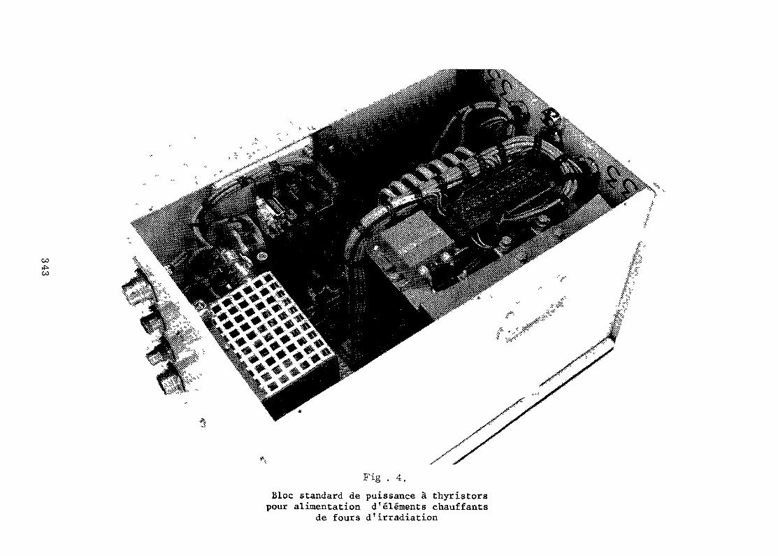
GOGO
Fig . 4.Bloc standard de puissance à thyristorspour alimentation d'éléments chauffants
de fours d'irradiation
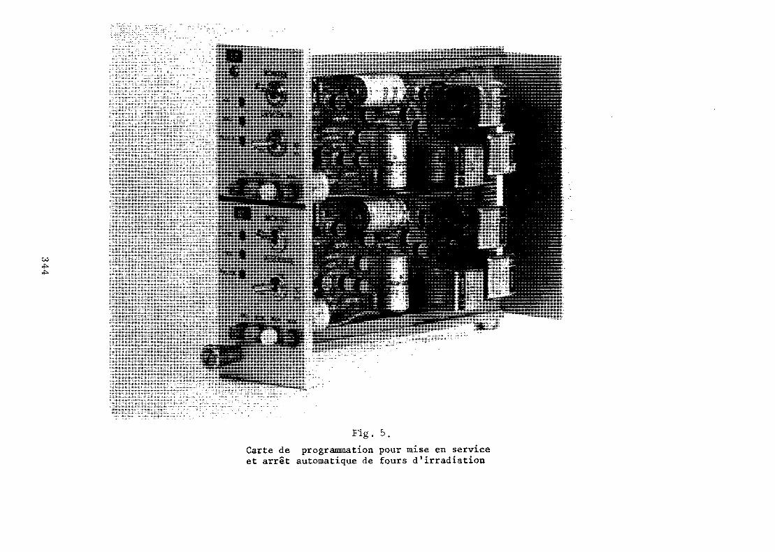
00
: Jit* |ií
"" "
Fig. 5.Carte de programmation pour mise en serviceet arrêt automatique de fours d'irradiation
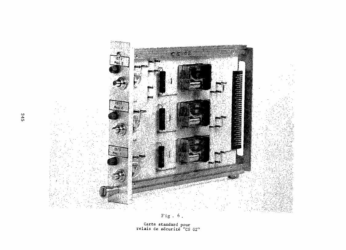
GO*>01
Fig . 6 .Carte standard pour
relais de sécurité "CS 02"
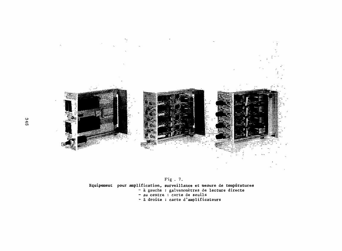
CO*>•
Fig . 7.Equipement pour amplification, surveillance et mesure de températures
- à gauche : galvanomètres de lecture directe- au centre : carte de seuils- à droite : carte d'amplificateurs
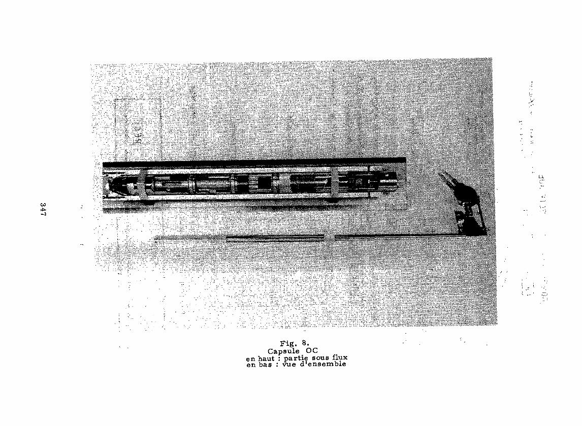
00
u
Fig. 8.Capsule OC
en haut : partie sous fluxen bas : vue d'ensemble
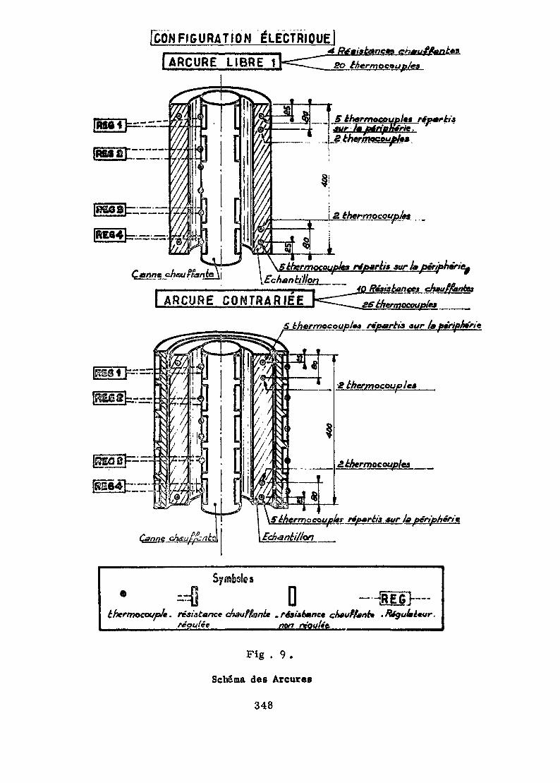
fcON F I G U R A T I O N élÉCTRIQUElJARCURE LIBRE
J S èhermocouplet répmrkia\ —^jfc 1 — — m - JT—>—— lf-^_î—. *
| ^rf-.
\2. thermocouples . _
URCURE CONTRARIÉE
5itermocoufJes rtparb* suri» périp\ f , , .« ^ * '\Echankilhn
chauffknfat
ocoupio* ripartta -sur ía
Canne ch
N^H|
t
i
1N
vX^/.v^
^
\sssV
sN
s^
i.ss^L
ijj> Iti-'ii
'
i
¡ i $\SeAermoet
1
'
£ thermocouple*
S. thermocouples
typist réfutréii sur la périphérie
Ech&nki/Jon
0éhermocoup/e. résistance chauffante .résàéance chauffant» .Régulateur.__ reculée__________/?0r^ re'oultt. _____________
Fig . 9 .
Schéma des Areures
348
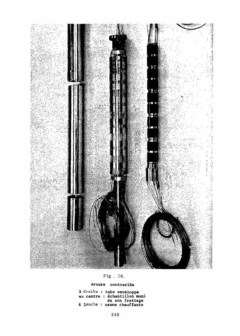
Fig . 10.Arcure contrariée
à droite : tube enveloppeau centre : échantillon muni
de son frettageà gauche : canne chauffante
349
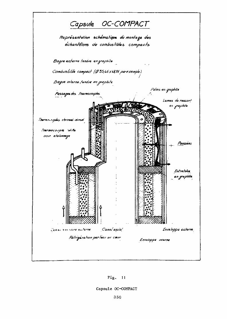
Capsule OC-COñPACT
Ft<3.préç>a.ni-otior> schéma. Hqt*. </u monf-a.q« c/*séchantillons de combustibles, compact
exrerna fa/idtn a.ngrapnil€-
Com¿>ifS>é/b!e compact
ffft .¿7 /
fassaan des>
mferae
Fig. 1 1
Capsule OC-COMPACT
350
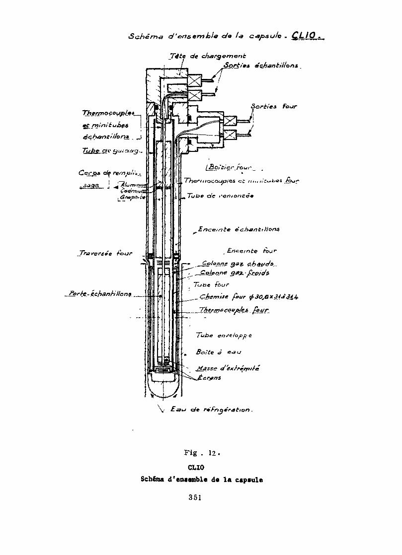
iSc.hérr>& d' 'ensemble c/o /«s c<y«t//c .
Tête de cfiar<j*m<&ni:Sortie^ échantillons
four
échantillon*..
Tube <y
TLoe four
_ Chemise feur $3Ofex£4*34,4.
V c/e
Fig . 12.
CLIOSchéma d'encemble da la capcule
351
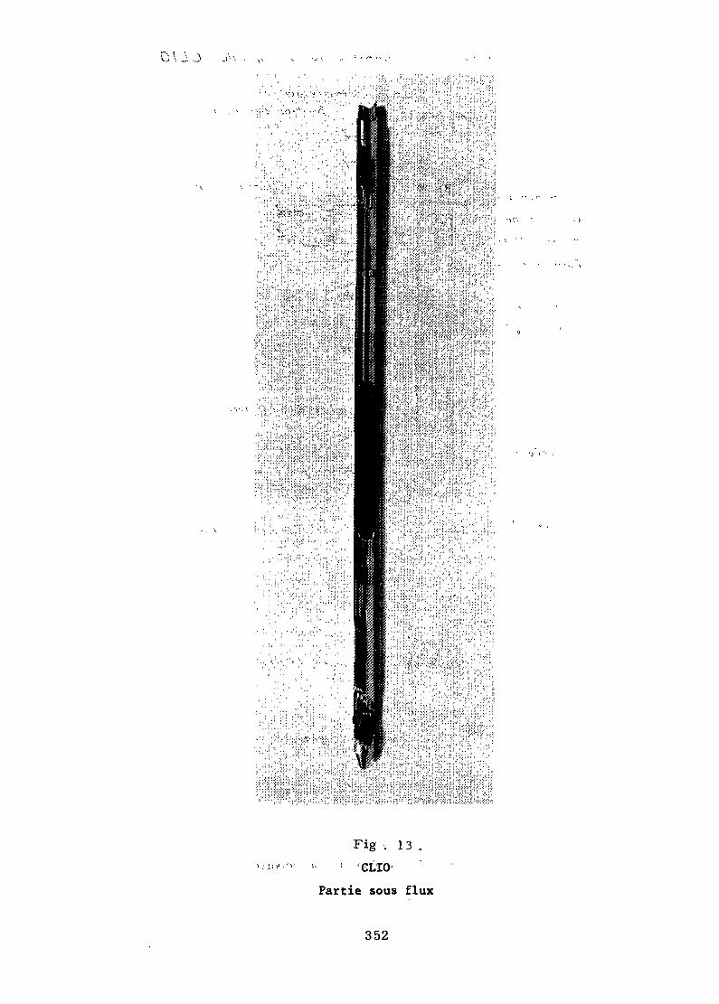
Fig - . 1 3 .
Partie sous flux
352
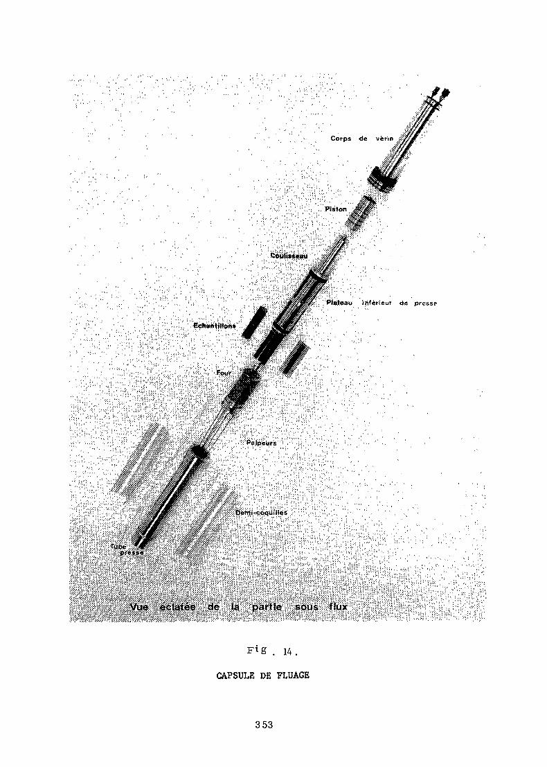
,! ".\ -Â:f' ':.: r >':;'./',/piéton '
, ' Plateau inférieur <Je presse
Fig . 14.
CAPSULE DE FLUAGE
353
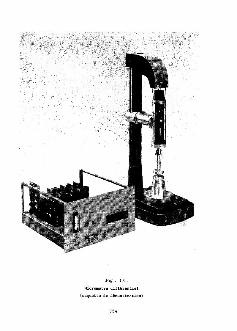
Fig . 15.Micrometre différentiel
(maquette de démonstration)
354
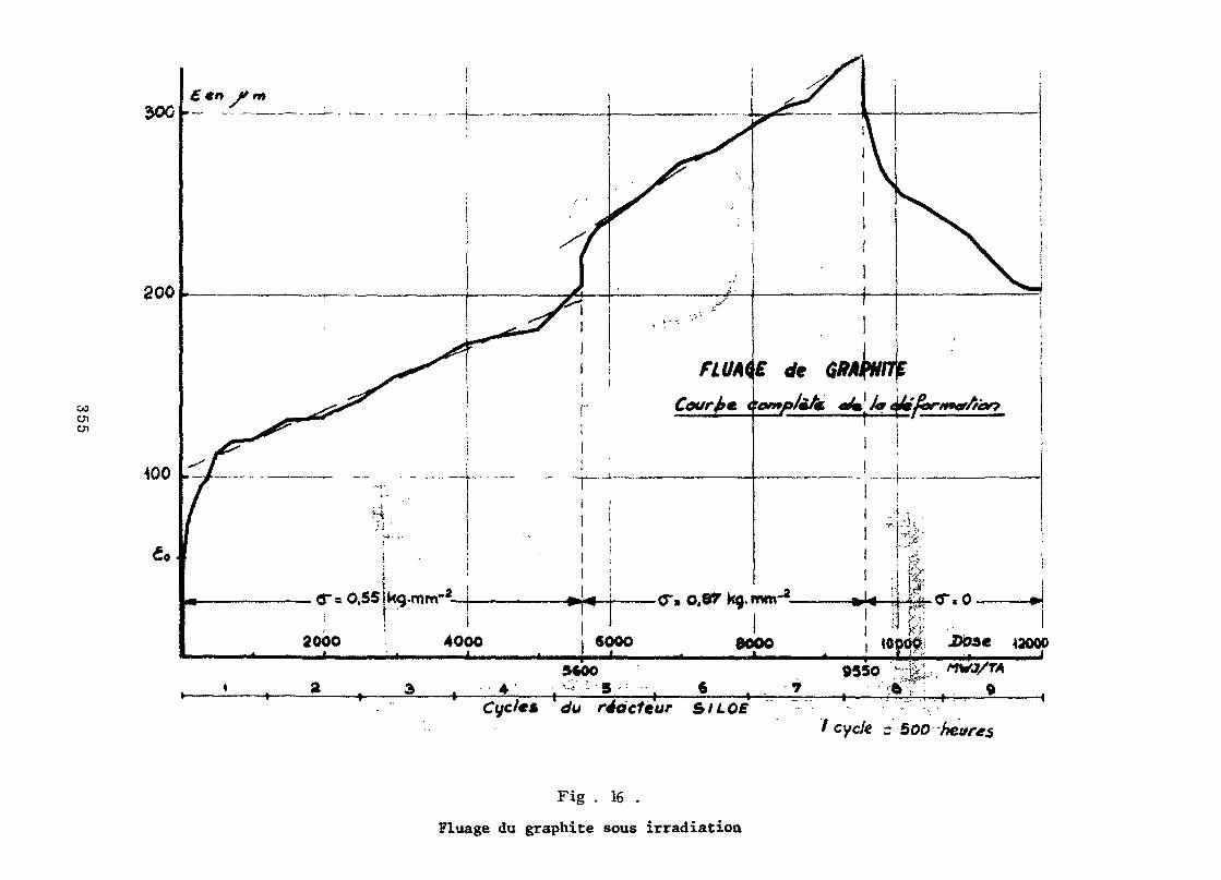
enen
soc
800
«oooo Dfcse 42000
Cc/c/e« c/u réacteur &ILÛEt cycle r 500 heures
Fig . 16 .
Fluage du graphite sous irradiation
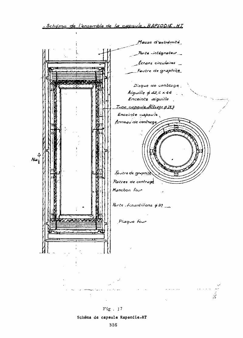
a qfe l'ensemble de Xa <z&£>s<j/e - RAPSO)l£.
^ circui<air*s
Feutre c/«
Uisc/ue de
Aiguille jé 4¿,
Enceinte <aiguiJle
c/t
P<a t'tes efe centra
n Pour
. é^n^nt'nions 5» cîJ _,_
/-our
Fig . 17
Schema de capsule Rapsodie-HT356
Fig . 18 .Capsule Rapsodia HT
357
Fig . 19 .
Capsule MINI-OCPartie interne
358
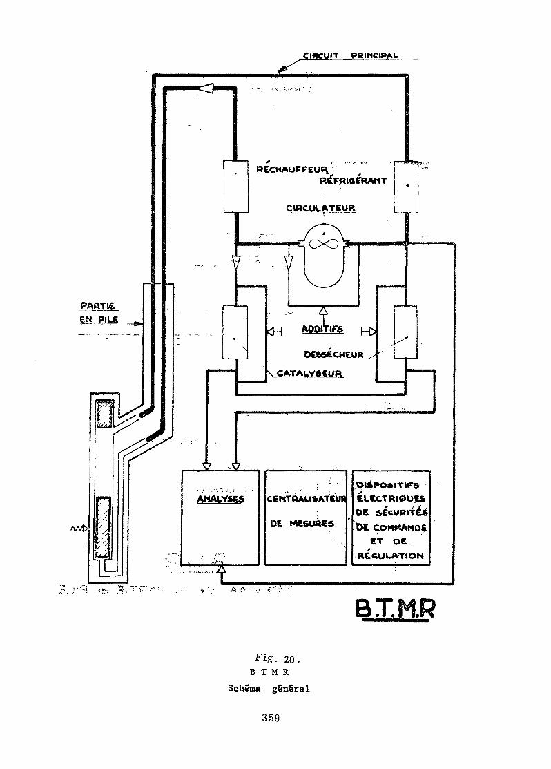
CIRCUIT PRINCIPAL
PARTISEN PILE
RECHAUFFEUR.REFRIGERAMT
CIRCÜLATEÜR
ANALYSES
" .':.!--i
. . • • • ' . ' ' ". • ,CEMTBAU&ATCW
DE. MESURES
t
Qisoos.TirsÍLCCTRI0UES
DE SÉCURITÉ^D£ COMMANDE
ET DEs
R£aUUATlON
BT.KR
. 20.B T M R
Schema general
359
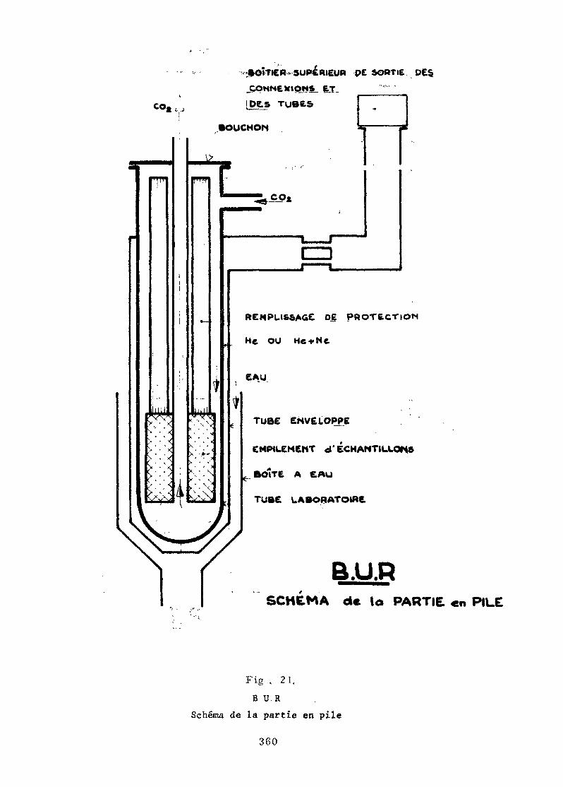
coa L_
ftO»T»£« SUPERIEUR 9C SORTIE
.CONNEXION», ET.
lots ruées
.BOUCHON
T
VN"*1
' " " ' » *
> X*
^^
ii
!
\
m\\X. r .
X,
^J
11
*
[r
»
!
.'
i
•IB
¿
¿
A
1=1
REMPLISSAGE DE PROTtCTlOM
He ou HetNe
TUÔE ENVELOPPE
EMPILEMENT d' ÉCHANTILLON
eBolTt A 6AU
TUBE LABORATOIRE* ^•'•Ww fct^^BF^^*^*^ » *^-* •*•
B.U.RSCHÉMA de la PARTIE «n PILE
Fig . 21.B U.R
Schéma de la partie en pile
360
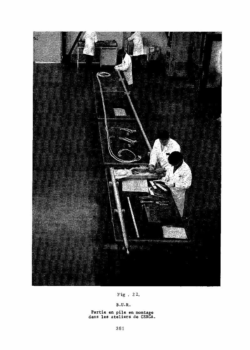
Fig . 22.
B.U.R.Partie en pile en montagedans les ateliers de CERCA.
361
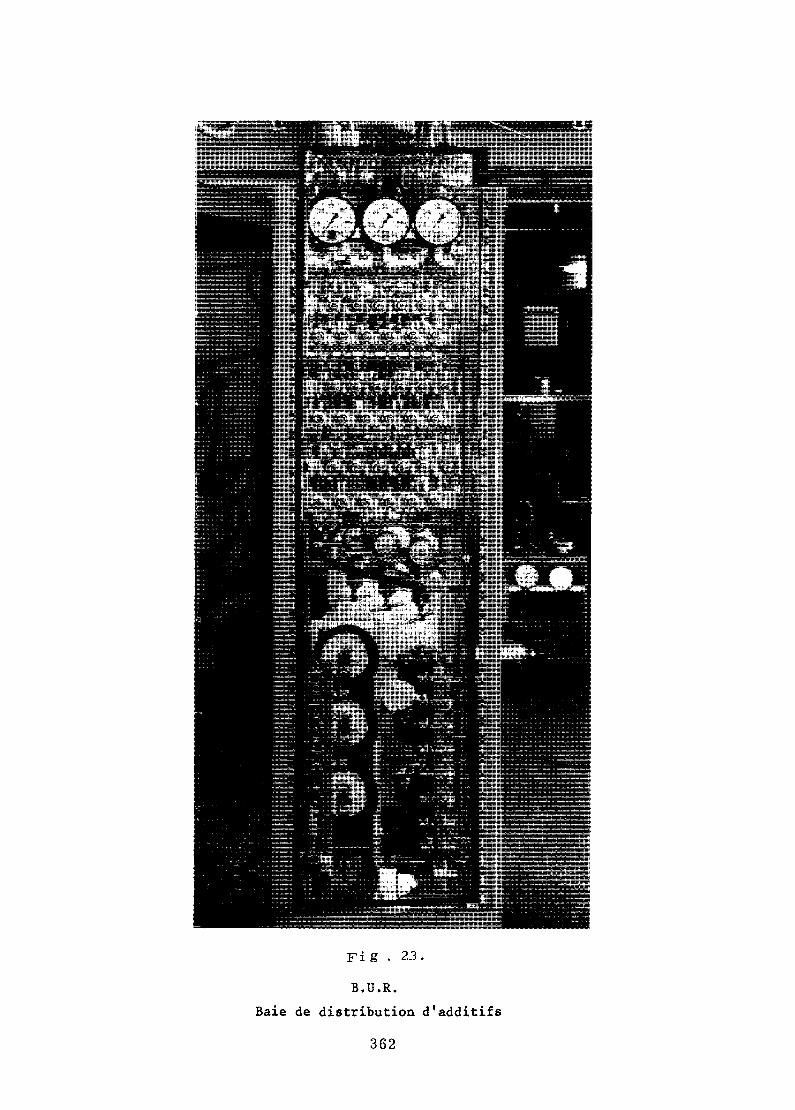
Fi g • 23.
B.U.R.
Baie de distribution d'additifs
362
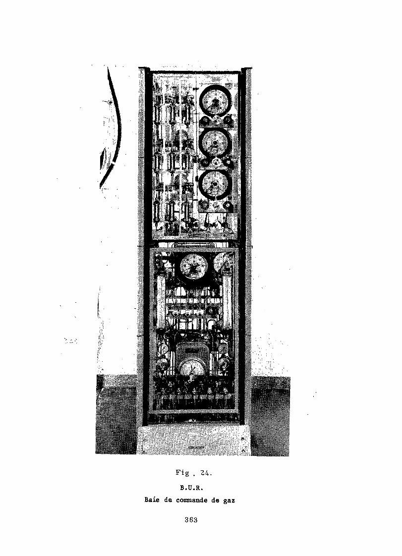
Fig . 24.
B.U.R.
Baie de commande de gaz
363
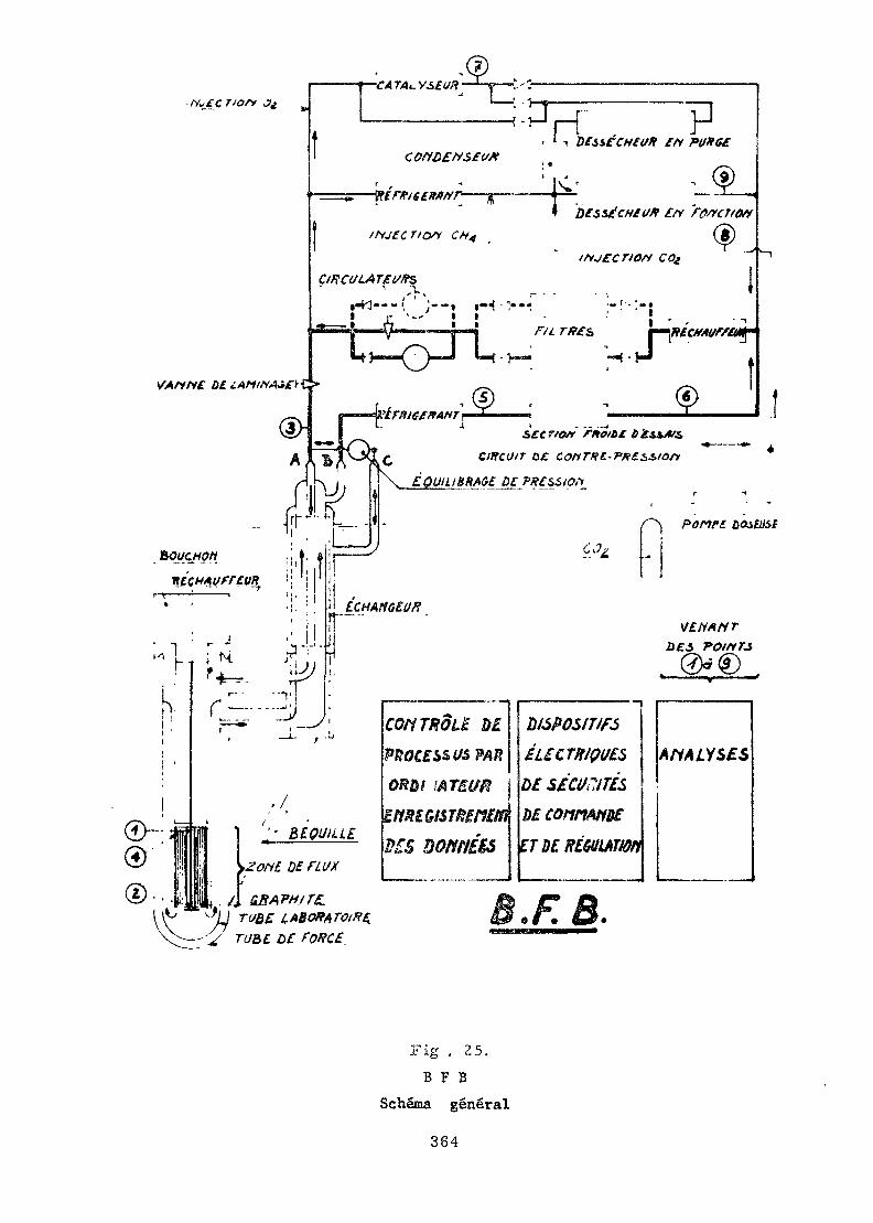
"ÇA TA L. V¿£í/ j—Ce——1 - '-
Fig . 25.B F B
Schéma gênerai
364
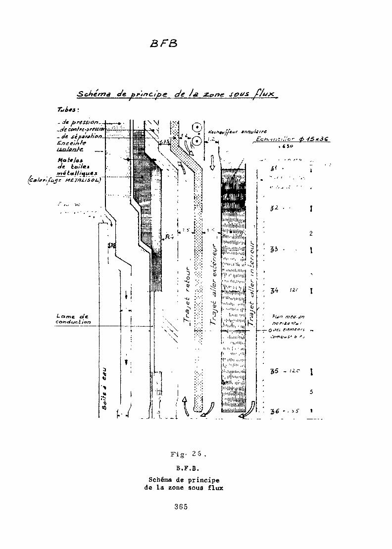
BF&
ma cíe, principe ç/e /g z.ç>ne setts
. Je pression.,.ale coafae-preum_ Je s¿p*r*tit>n.£/} ceinte
Fig-
B.F.B.Schema de principe
de la zone sous flux
365
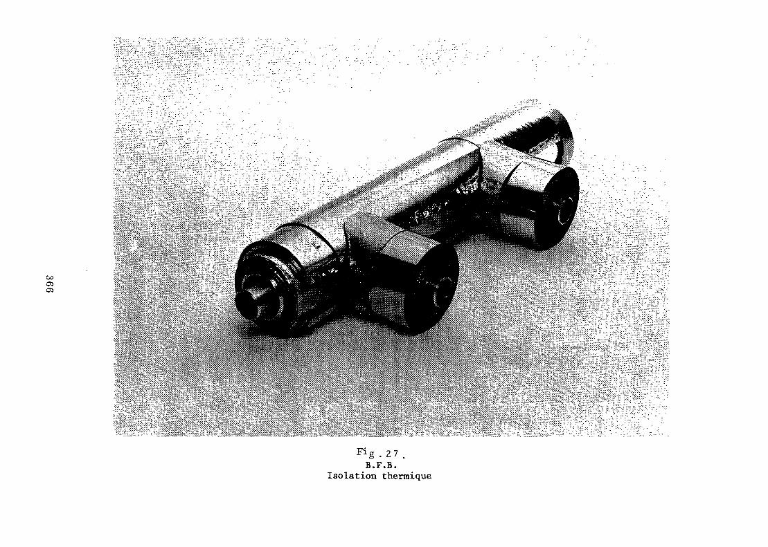
O5
^g .27 .B.F.B.
Isolation thermique
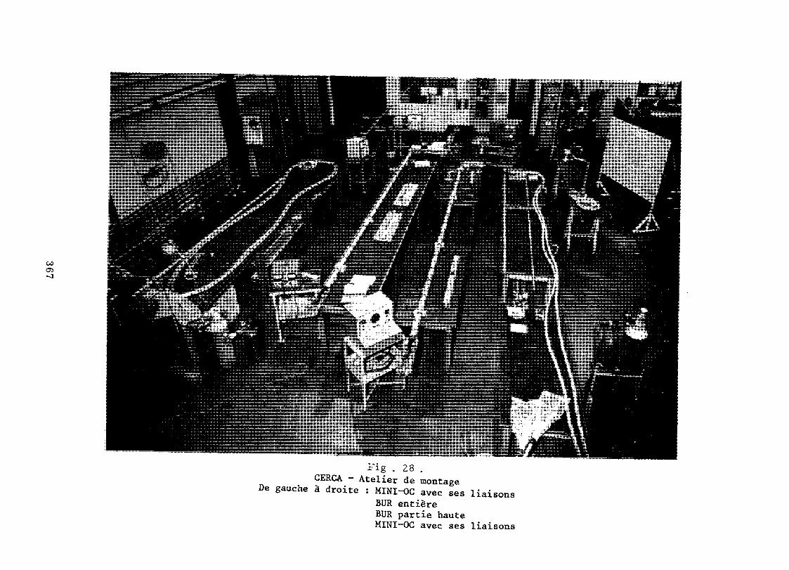
GO05
Fig . 28 .CERCA - Atelier de montage
De gauche à droite : MINI-OC avec ses liaisonsBUR entièreBUR partie hauteMINI-OC avec ses liaisons
- REFERENCES BIBLIOGRAPHIQUES -
Il} SEGUIN (M.), ARRAGON (Ph.), DUPONT (G.), GENTIL (J.), TAMIS (G.)Quelques dispositifs d'étude du graphite dans les piles piscines.Rapport français CEA-R 2516 , 1964.
[2] SÉGUIÎI (M.)Considérations générales sur les irradiations d'échantillons dans lesréacteurs.Rapport français CEA-R 2801 , 1965.
l3j APRAGON (Ph.), GENTIL (J.), SEGUIN (M.)Dispositif d'irradiation.Brevet français n° PV 977.826 , 1964.
COSTÉ de BAGNEÂUX (C.), DUPONT (G.), FRANZETTI (P.), SEGUIN (M.)Nouveau four d'irradiation nucléaire.Brevet français n* PV 902.404 , 1962.
/57 AXELPJW) (C.), THOMAS (G.)Convertisseur pour la mesure des caractéristiques des courants électriques,Brevet français n° PV 125.869 , 1967.
THOMAS (G.)Bloc de déclenchement pout thyratrons.Brevet français n° PV 125.870 , 1967.
[1] THOMAS (G.)Bloc de puissance asservi pour alimentation d'éléments chauffants.Brevet français n' PV 125. R71 , 1967.
AXELRAD (C.)Procédé de mesure de microdéplacements et micromètre différentielpour cette mesure.Brevet français n° PV 6.937.181 , 1969.
368
EXPERIMENTAL TECHNIQUES FOR FUEL TESTINGIV RESEARCH REACTORS
by
N. Raisifi, Boris Kidric Institute of Huolear Sciences, Vinca
Yugoslavia
Abstract
Some experimental techniques for fuel testing in researchv
reactors which are in routine use at Boris Kidric Institute aredescribed» The main aim was to demonstrate the type of ex-periments which can be performed in a developing country whichhas a critical assembly and a medium sized research reactor»The proposed expérimente are : testing the purity of fuel by reactoroscillator technique, determination of the nuclear parameters ofa fuel element by single rod experiment, and determination ofthermal conductivity of fuel during irradiation by the capsuleirradiation technique.
1. INTRODUCTION
,v ,In the course ,of fulfillement of the programme ofresearch ana development of nuclear power in Yugoslavia seve-ral experimental techniques have i>een applied for testing thefuel at different stages of the technological process of fueldevelopment and fabrication. Some of them require the use ofresearch reactors, especially when the purity and the nuclear
:;-,--: , : . < • • • - - , . . .characteristics of the fuel are the okqect of interest.Institute of nuclear sciences in Beograd dispose
with two reactors buildt in 1959. The first is a D0O criticali . . , /*assembly RB, intended for reactor physics experiments andtraining of personal in reactor operation. The second is aD O-slightly enriched uranium medium - power research reactorRA intended for isotopes production, samples irradiation andsolid state physics experiments. These two reactors represent
369
a good combination which can cover a broad range of needsarrising during the fulfillement of the research and develop-ment programme in nuclear fuel.
In this paper some of the experimental techniqueswhich are in the use on these reactors are described with themain purpose to demonstrate the applicability of researchreactors in the fuel development programme.
2. THE TESTING OF FUEL FOR PURITY
The fuel is subjected to the purity testing troughoutthe complete technological process of fuel fabrication. It isof particular interest to test the changes in the fuel purityduring those processes in course of which the introduction ofinpurities is no more recoverable, as for example, pelletisa-tion, pressing and sintering of U02- At the same time the com-plete chemical analysis at that stage is not of particularinterest, but rather an indication of nuclear purity. For thesereasons the reactor oscillator technique is accepted, in orderto express all chemical inpurities in the basic material in theform of equivalent of boron.
Reactor oscillator ROB-1 (1) has been constructedfor the reactor RB to fulfill both the requirements for mea-surement/the nuclear characteristics of materials and forreactor kinetics experiments. It has the following basiccharacteristics ;
-4Frequency range 10 - 0.7 Hz.Form of oscillations is sinusoidal or quadrangularError in the amplitude of the. first harmonics 1%Error in the phase shift determination < 10'The electronic part of the oscillator is used for
the analysis of the reactor response signal. The signal ismultiplied by a simple-periodic functions generated in an ana-logous circuit during the oscillator movement. Both signalsare multiplied while in analogous form. The resulting signalis converted to a digital form and the integration follows.
370

Thus, the first harmonics of the reactor output signal is ob-tained due to the orthogonality of trigonometric functions.
As it is well known the method of measurements ofnuclear characteristics of material is a relative one,. It isbased on linear correlation between the perturbation of theeffective reactor multiplication factor and nuclear charac-teristics of material, and comparation of the reactor outputsignal produced by a sample and the corresponding signalproduced by the material whose nuclear characteristics areknown.
As a reference standard, boron samples of the welldetermined isotopic composition are normally used. For thedetermination of the purity of uranium the "Merck" standardU02 (IV), ceramic grade/ nuclear pure M = 270.03 is used.According to the atest, boron equivalent of the present im-purities, independent on the way the analysis is made, is-4equal to 1.2-10 %. On this basis several samples from diffe-rent laboratories in Europe are. tested and the satisfactoryaccordance is found.
The uranium samples are canned in nuclear pure alu-minium. Approximately the same quantity of uranium is packedin one canner in all experiments. The samples are subjectedto the rectangular oscillations in the thermal pit of theRB reactor with a period of the order of 50 sec and thetransient time of approximately 1 sec. The mechanic oscilla-tions are obtained by the pneumatic mechanism PP-2 (2). Firstharmonics of the reactor response is corrected, for the neu-tron self absorption, the differences in the. canner weight,possible changes in reactor power during experiment, and thetotal weight of the sample. The total error in the experimentis estimated to be 3%. The comparation between the signalof the sample and the standard is made.
Usually it is accepted that the nuclear purity ofuranium is conserved during the process of pressing, presin-tering, sintering and grinding if all sampled show the diffe-rence which is in the frames of the experimental error. Thetypical results of a series of measurements during the fabri-cation process are presented in TABLE 1 (3).
371
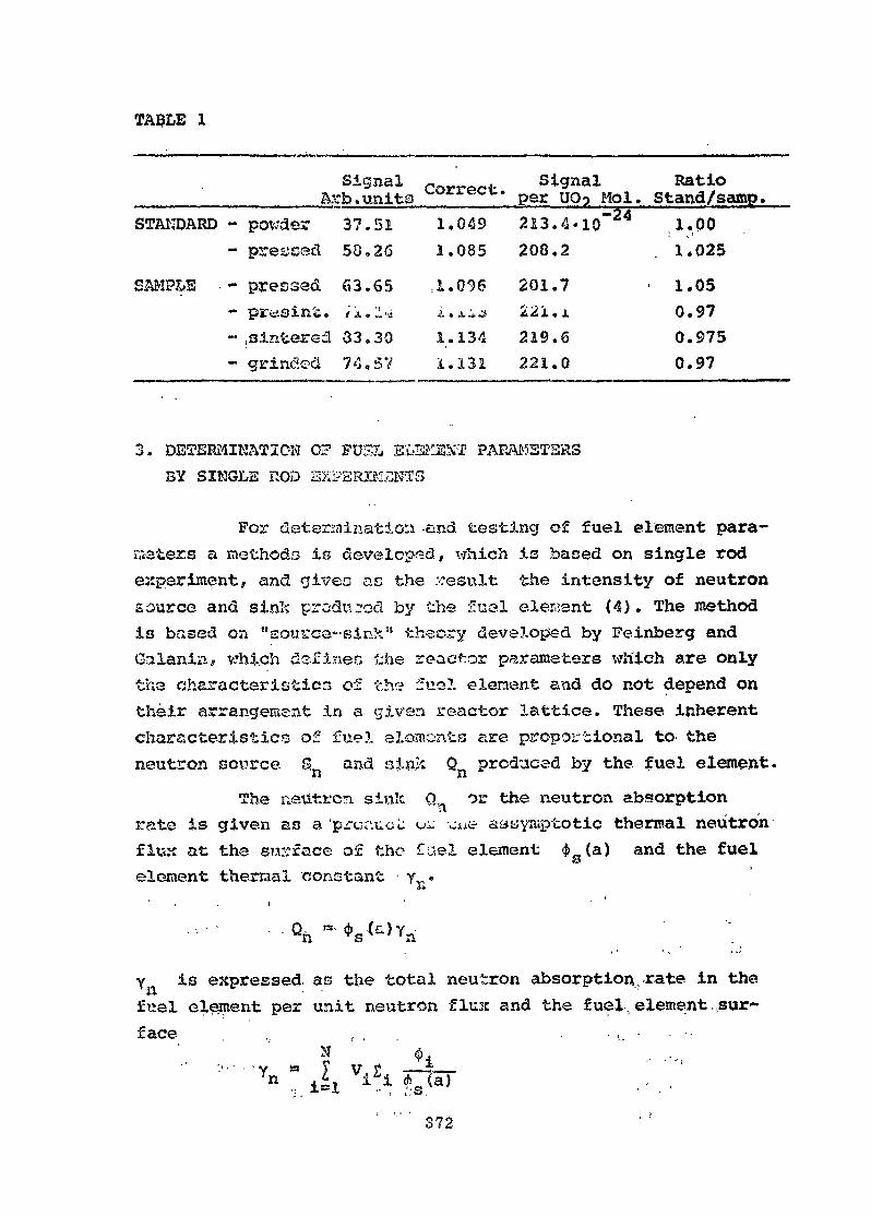
TA9LE 1
SignalArb . units orrec •STANDARD
SAMPLE •
- powder- pressed- pressed- presin-i;.- wintered- grincled
3. DETERMINATION! 0?
37.58.63 *;i..33.74.
FUS
512665_-j305V
11,1À1I
.049
.085
.096
.XiJ
.134
.131
Signal1 per UO5 Mol.213208201221219221
.4«10~24
.2
.7
. i
.6
.0
RatioStand/samp.111000
.00
.025
.05
.97
.975
.97
IL ELSKSST PARAMETERSBY SINGLE ROD EXPBRIMJ3STS
For determination and testing of fuel element para-meters a methods is developed, which is based on single rodexperiment, and givec as the result the intensity of neutronsource and sink produced by the fuel elegant (4). The methodis based on "source-sink" theory developed by Feinberg andGalanin, vrhi.ch defines the reactor parameters v?h'ich are onlytha characteristics of the fuel element and do not depend ontheir arrangement in a given reactor lattice. These inherentcharacter is t ice of fuel elesnents are proportional to- theneutron source, s and s£n;c Q produced by the fuel element.
The neutron siïiîc Q^ or the neutron absorptionrate is given as a prcr.ucL u^ c^e aawymptotic thermal neutronflux at the surface of the fuel element 4>_(a) and the fuelS3element thermal constant • y^.il
y is expressed as the total neutron absorption,rate in thefuel element per unit neutron flust and the fuel element,.sur-face ,, , , . - i, • • •-' ' N O .
n "~ £ •? i A"
372
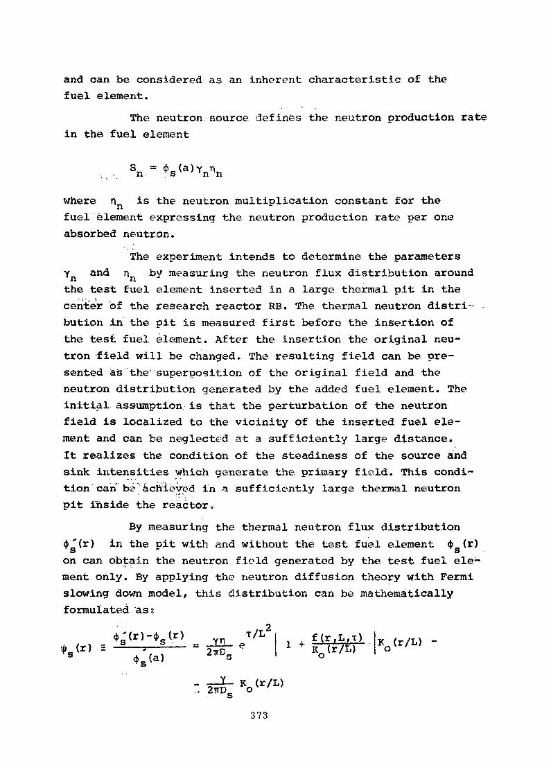
and can be considered as an inherent characteristic of thefuel element.
The neutron,source defines the neutron production ratein the fuel element
S *"• (5n- v;
where n is the neutron multiplication constant for théfuel element expressing the neutron production rate per oneabsorbed neutron.
The experiment intends to determine the parametersYn and nn by measuring the neutron flux distribution aroundthe test fuel element inserted in a large thermal pit in thecenter of the research reactor RB. The. thermal neutron distri-bution in the pit is measured first before, the insertion ofthe test fuel element. After the. insertion the original neu-tron field will be changed. The resulting field can be pre-sented as the1 superposition of the original field and theneutron distribution generated by the added fuel element. Theinitial assumption is that the perturbation of the neutronfield is localized to the vicinity of the inserted fuel ele-ment and can be neglected at a sufficiently large distance.It realizes the condition of the steadiness of the source andsink intensities which generate the primary field. This condi-tion can b<? achieved in a sufficiently large thermal neutronpit inside the reactor.
By measuring the thermal neutron flux distribution4>'(r) in the pit with and without the test fuel element 4>_(r)S Son can obtain the neutron field generated by the test fuel ele;ment only. By applying the neutron diffusion theory with Fermislowing down model, this distribution can be mathematicallyformulated ass
21 + f(r,L,T)
K (r/L)oK <r/L) -o
vr/L)373
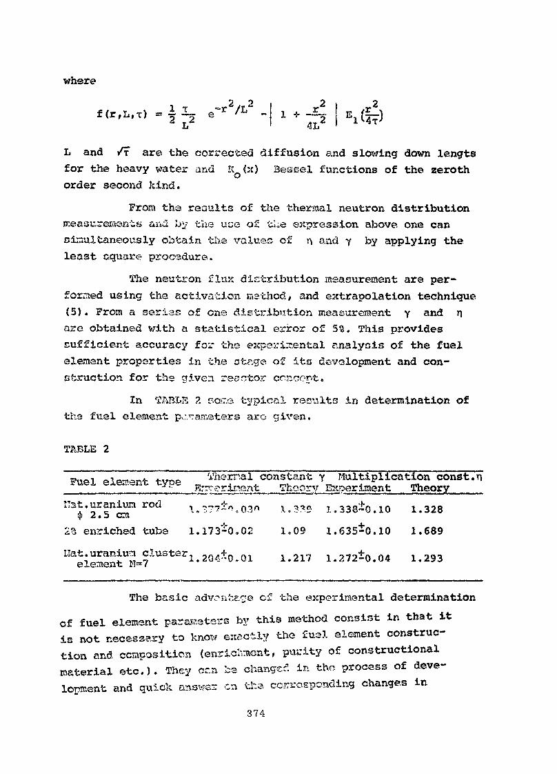
where2f (r,L,T) « ~ I 2
L and /f are the corrected diffusion and slowing down lengtsfor the heavy water and KO(X) Bessel functions of the zerothorder second kind.
From the results of the thermal neutron distributionmeasurements and lyj the use of tLe expression above one cansimultaneously obtain the x^aluec of r\ and y by applying theleast eguare procedure.
The neutron flux distribution measurement are per-formed using the activation method, and extrapolation technique(5). From a sérias of one. distribution measurement y and narc obtained with a statistical error of 55. This providessufficient accuracy for the experimental analysis of the fuelelement properties in the otege of its development and con-struction for the given realtor concent.
In TABLH 2 rsoïT.e typical results in determination ofthe fuel element parameters arc given.
TABLE 2
ele»*nt tvne Vhernal constant y Multiplication const,.«I* uy^c i?.. ».<M««4. hoory Experiment Theory"st.uranivn rod
0 2.5 cni25 enriched tube
l. 1î77 .03«1.173-0.02 1,09
1.338*0.101.635*0.10
1.3281.689
eiSt ?1113 2'1-20 0*01 1'217 1-272*0.04 1.293
The basic advrnta-ge cf the experimental determinationof fuel element parameters by this method consist in that itis not necessary to know exactly the fus.l element construc-tion and composition (enricliment, purity of constructionalmaterial etc.). They cc.n be changed in the process of deve-lopment and quick answer en the corresponding changes in
374
nuclear characteristics of the fuel element can be obtained.Besides, the complexity of the construction frequently raisesdifficulties in the theoretical determination of nuclear para-meters of the fuel element, thus experimental determinationof some global parameters of the fuel element can be desirable.
Possible application of the described method con-sist also in the nondestructive determination of the burn-upof the irradiated fuel element. In this respect some analysisare made, which show that the burn-up for the natural uraniumcluster by measuring y and n constants can be obtainedwith an accuracy of the order of 1000 Mwd/t. Unfortunatelythe experimental arrangement of the reactor RB does not allowthe work with the intensively irradiated fuel, so the investi-gation were limited to the theoretical study and few measure-ment with the irradiated fuel cooled for several years. Theobtained results are promising.
4. TESTING OF THE THERMAL CONDUCTIVITY OF FUELDURIHG IRRADIATION
Testing of the thermal conductivity of fuel duringthe irradiation in the reactor has two main purposes. First itis important to know how the thermal conductivity changeswith the temperature of the sample, and second how the conduc-tivity behaves during the irradiation. Both informations arean important proof of the quality of the fabricated fuel/whichdoes not require material testing in the hot cells. For thisreason method of thermal conductivity measurement is addoptedas one of the standard methods for testing the mechanicalcharacteristics of the fabricated fuel pins. For the irradiationof the samples RA reactor is used. The constructive characte-ristics of the RA reactor offer the possibility to performthese experiment on a rather simple way. One standard fuelelement is extracted out of the reactor, and on its positiona dummy fuel element consisting of the cooling tube and thecapsule for irradiation is inserted. Addapting the construction
375
of the cooling tube the flow of heavy water trough the fuelelement tube is adjusted in a way to allow the appropriatecooling of the capsule. In a standard experiment the fuel pinis inserted in a helium fieled tube, which is cooled fromoutside by the heavy water.
For the measurement of thermal conductivity thedirect method is used based on determination of the heat gene-ration in the fuel, and measurement of the temperature gradientin the radial direction of the fuel pin (6).
Determination of the? heat generation in the fuel isbased on the continuous registration of the thermal neutronflux inside the pin, and temperature gradient measurementallong the pin radius. Neutron monitoring and registrationis done by so called "neutron coax" detectors. The detectionis based on the absorption of neutrons in a silver head andsucessive emission of the 3 particles from the radioaativeAg-110 and Ag-108. The fuel temperature detection is doneby usual thermocouples.
In a standard experiment three neutron-coax detec-tors are used to give the informations on the axial distri-bution of the thermal neutron flux and its changes duringthe irradiation. At the same time nine thermocouples are re-gistering the radial and axial temperature distribution inthe sample. When the reactor operates on the maximal powerof 6.5 MW the thermal neutron flux at the position of the
13 2irradiated sample reaches the average value of 3-10 n/cm sec.The temperature inside the fuel pin is of the order of 440 Cwith the temperature gradient allong the pin radius of110°C. The higher temperatures were difficult to reach at thisstage of development, because of the initiation of ^2^ boilingwhich is at the same pressure inside the test-tube as the allinside of the reactor.
The irradiation of the sample is usually done in19 19 2the fluence range of 10 - 5-10 n/cm , which require the
continuous reactor operation from 15-75 -days. At the presentstage of fuel development programme the technological process
376

of fuel sintering is considered as satisfactory if the irra-diation test does not show some discontinous changes of ther-mal conductivity during irradiation, and only slight decrease
19 19 2of its value in the range of 10 - 2-10 n/cm . Furthertrends in the programme, are oriented in the direction of in-creasing the temperature of the samples and prolongation ofthe irradiation time up to the value corresponding to theoptimal burn-up in the heavy water power reactors.
REFERENCESs
1. M.Petrovid et al.: Pile Oscillator ROB-1, IBK-359 (1966).2. A.Kocic", V.Markovids Reactor Oscillator PP-2, XI Conf.
ETAN-a (1967 (in serbocroatian).3. V.Markovid, A.Kocic*; Determination of the Impurities in
Uranium by Reactor Oscillator Method. XIII Conf.ETAN (1969)(in serbocroatian).
4. N.Raiiid et al. s Determination of Reactor Parameters bySingle Rod Experiment, Bull.Boris Kidrifi Institute,Vol.20, Nucl.Eng.No 2 (1969).
5. Neutron Thermalization, IAEA, Tech.Reports Series Mo. 68.6. A.Pavlovid: Irradiation of Sintered UÛ2 in RA Reactor.
IBK-E-14-16-00-29 (1969) (in serbocroatian).
377
PROBLEMS INVOLVED IK THE PROCUREMENT OP IN- PI LEASSEMBLIES FOR NUCLEAR RESEARCH
R.Straton and P.TaylorU.K.A.E.A.
Harwell, Didcot, Berks.
Abstr^-ct
The task of providing eq'Jiprrerit for ca.rr.virf" out irradiationprogrammes has many restraints, restrictions arid difficulties. Thepaper presents some of these. It. is suggested that they can bereduced to a minimum by the type of org-ar.isatior. referred to inar-other paper
PROBLEMS INVOLVED IM THE PROCUREMENT OF IN-PILE ASSEMBLIES FORNUCLEAR RESEARCH
Introduction1. The Project Engineer is responsible for design, development, manufacture,testing and commissioning of in-pile assemblies for use by scientists intheir irradiation programmes. Such a task is surrounded by many restraints,restrictions, and difficulties. This note surveys the problems involved.
These fall under three headings:(a) Problems'related to engineering design in its broadest sense,(b) Problems arising because of the scientific research element of the
work.(c) Problems arising from the nuclear environment.
This note will only cover (b) and (c) above, the principal difficultiesinvolved being as follows.2« Time Schedule
A limited time for completion is a problem in all design work, but isintensified by
(a) the research being closely tied up with target dates for infor-mation in support of large, expensive, national power programmes,
(b) the rapid advance in modern research and' development requiring'up to the minute' information,
(c) the desire of the scientific teams to lead the field.
379
3. CostThe unusual nature of the work makes many traditional methods of cost
control difficult to employ. By conventional engineering standards costsare high owing to
(a) the need to produce rigs and components, singly,(b) the tendency to continually mooify and generally up-rate rigs,(c) the amount of development we Sc normally associated with a
programme,(d) the high standard required in the completed equipment,(e) the quality of labour required for the manufacturing/assembly
processes.4. Standards of Manufacture
Owing to the high standard of workmanship required in the manufactureof in-pile equipment difficulties can arise in finding acceptable contrac-tors. Once established however, such an organization has been found to bevirtually free of labour relations problems, possibly because of the intel-ligence of the craftsmen employed, the .job satisfaction created, and thehigh standard of the working environment.
5. Reactor EconomicsResearch reactors must be run as economically as possible and so maxi-
mum loading must be maintained. As a result the Project Engineer findshimself dealing with the often conflicting problems of flux, neutronspectrum, garama heating, irradiation-hole size, reactor-cycle duration,pressure of other users for the saine position, reactor power changes,operational stability, neutron absorption, irradiation charges and financegenerally.
6* Changes In User Requirements
By its nature, scientific research in any field is in a continuousstate of change. Where long-term design and development is involved it isunusual to be able to complete a project vath the same aims and require-ments as when it started»
Changes in user requirements during a project's evolution are costlyand time-consuming. The Project Engineer will often build in flexibilitywhere he can, but this often invitej; changes. The desire of the ProjectEngineer to have the specification 'frozen' as early as possible conflictswith the scientist's understandable need to keep all his options open tothe latest possible stage,
7. Reactor Environment
Nuclear research is largely a study of a hostile environment and itseffect on materials. Unfortunately these self-same materials have oftento be used in carrying out the research. The effects of neutron damage,temperature gradients, high temperatures, in compatibility, lack of accessto the equipment, limited space, limited choice of materials, radioactivity,
380
and the production of toxic materials are all problems with which theProject Engineer has to deal. Despite these difficulties he is expectedto provide laboratory conditions for tho user's samples,, with no hazard topersonnel or the reactor*8» Provision and Use of NuclcarJData for Design Purposes
The basic measurements needed to overcome some of the problems notedearlier must be obtained from the reactor. Earlier rigs can sometimesprovide some of this, but at is necessary to carrv out careful flux andgamma-heating measurements in specialized rigs, to provide reliable designdata. The rig containing the users specimens is sometimes, hov.-ever, theonly means of finally assessing the conditions in the irradiation positionat any time, and a conflict frequently exists between the scientist'sexperimental requirements and the need of the engineer to assess theperformance of his design. For example an engineer may prefer the firstrig of a series to be used as a test of performance and temperature distri-bution. The user however normally wants his results immediately. Thisconflict has been largely overcome by the accurate and flexible simulationswhich can now be made by means of analogue techniques or computer programs.Their accuracy however still depends on the accuracy of the input datacoming from the calorimetry and flux-scan rigs referred to above.9. Engineering Design Problems^
The design problems peculiar to nuclear experiments arise out of thesmall space available, the choice of materials, the need to keepneutron absorption to a minimum and the twin problems of high (or low)temperature and heat removal (or insulation). Specialist rigs such ascreep rigs also involve accurate measurement of dimensional changes.Neutron damage and swelling can reduce th^ life of an experiment andreduce its reliability, and complexity j s often the price to be paid fora rig with reloadable samples. Extensive and expensive heater developmentprogrammes are operated to keep up with the quest for higher temperatures,and a similar situation exists relative to thermocouples.
Planned and far-seeing development is the key to many of theseproblems, but all too often the user is not prepared to pay for long-termdevelopment which may have uncertain results.
The whole subject of equipment design must revolve around the safetyaspect. Here the areas of administrative control and calculation andmeasurement come together. Many administrative controls exist solely toensure that all the safety aspects have been considered, that the equipmentcan only operate in a safe manner, and that any failure modes will also besafe. Nevertheless proof of the safety of a rig or loop is required beforeits irradiation, and adequate testing must be imposed on the above controls,11. Summary
A Project Engineer engaged in the provision of nuclear research equip-ment is a specialist involved in solving the problems outlined earlier inaddition to the everyday general engineering difficulties. The problemsdivide into the Administrative category (pressures of time, cost, labour,economics, etc.) in which he is helped by his organisation and management,
381

and the Technical category (measurement, hostile environment, development,etc.) in which he uses scientific and technological skills. The abovecategories combine in a third area - Safety, In addition a considerableknowledge is required of disciplines outside the engineer's immediatefield, for example instrument technology, materials science, chemistry,and nuclear physics, and he must keep in close touch with the expandingareas of knowledge in which his user/customer is working.
382
SOME ASPECTS OP THE UTILIZATION OP .THE -ROMANIAN RESEARCHREACTOR IN NUCLEAR ENGINEERING
P. Popa ' •..-.-
ABSTRACT
The paper presents a brief review of the principal research activitieson nuclear engineering which have been carried out on the Romanian .S MWreactor. Material trials and hum-up studies relating directly toanalyses of nuclear data have been undertaken in conjunction with researchon reactor control and heat transfer.
BESUME .
D*une façon brève, sont passées en revue les principales activitésde recherche, visant le génie nucléaire, effectuées dans le réacteurroumain de 3,5 MW. .,Bn correspondance directe avec les études desdonnées nucléaires, les essais des matériaux et l'étude du "burnup"ont été effectuées à côté des recherches concernant le contrôle duréacteur et le transfert de chaleur.
A partir de 1957» la Roumanie dispose d'un réacteur de recherchede 2 MW. Il s'agit d'un ensemble critique à l'uranium enrichi, modéréet refroidi par l'eau ordinaire et qui possède les facilités pour laproduction de radioisotopes. Les recherchas effectuées dans ce réacteuront commencé surtout sur dos problèmes liés à la physique nucléaireet du corps solide et également à la physique du milieu multiplicateuret dans le début même, les aspects de la recherche technique ont étéenvisagés et après ils ont été développés d'une façon continue. On estarrivé, dans les dernières années, à donner à la recherche de la physiqueet-de la technique des réacteurs à caractère prioritaire.
L'expérience de la recherche dans ce domaine a été accumuléedans trois directions principales. Tout d'abord sont les études desconstantes nucléaires pour les réacteurs et les études dès réseaux»
A côté du réacteur, pour ces types de recherches, ont travailléégalement deux ensembles sous-critiques, mis en marche depuis quelquesannées.
383
Deuxièmement, c'est la dosiaétrie des neutrons. Dans le derniertemps on a été préoccupé surtout par les changements du spectre desneutrons avec l'épuisement du combustible nucléaire dans le coeur, etpar des études concernant le taux de conversion*
Un autre champ d'activité a été lié aux problèmes de la techniquedes réacteurs. Il est bien évident qu'on ne peut pas faire uneséparation nette entre la physique et la technique des réacteurs.
Commençons ce chapitre par les études effectuées sur lesmatériaux destinés à la construction du coeur. Premièrement sont lesirradiations des matériaux qui font partie du coeur d'un réacteur ouceux qui sont envisagés dans ce but et toutes les mesures et les étudesbien connues; réalisées au cours de ces irradiations ou après. Uneplace importante est occupée par les études concernant le "burnup".Ces études ont été faites surtout par des moyens expérimentaux nondestructifs. Une bonne corrélation calcul-expérience dans le domainede l'épuisement du combustible peut conduire à des programmes trèséconomiques pour digérer le "burnup" d'une façon optimum, dans lesréacteurs de recherche et dans les réacteurs de puissance également.Bans les recherches sur la technique des réacteurs nous avons développéaussi les études de transfert de chaleur*
Ont été abordés en même temps les problèmes de "burnaut" et aussiles autres aspects liés à l'utilisation des agents caloporteurs àdouble phase.
Particulièrement, on a développé un groupe d'étude concernantle contrôle et l'automatisation des réacteurs.
Les résultats expérimentaux obtenus sur la dynamique des réacteursont permis de préciser la possibilité de réaliser un contrôle automatiquedu démarrage.
Il reste encore, bien entendu, beaucoup de détails sur les aspectsd'utilisation du réacteur roumain de recherche dans le génie nucléaire.A titre d'exemple, l'expérience acquise nous a permis d'augmenter lapuissance thermique du réacteur de 2 à 3,5 Jfff.
384

En conclusion, il est certain que les études sur les aspectstechniques dans la construction des réacteurs conduisent à uneexpérience utile pour les chercheurs dans le génie nucléaire, etsurtout l'application industrielle qui est le but final d'unerecherche quelle qu'elle soit.
y d'une importance égale j c'est la formation desspécialistes capables d'aborder les charges difficiles d'unprogramme nucléaire»
385

SOME COMMENTS
byJ0 A, L. Robertson
on Papers Presented to theIAEA Panel on
Engineering Programmas in Research Reactors27 - 31 July 1970
Now that we have heard the prepared papers and the discussionof these papers, let us seek areas of agreement.
The second day we were invited to consider three types of countries t1) A country with a research institute but no nuclear power programme,2) A country intending to buy power reactors,3) A country wishing to build power reactors.
If the first country wants to conduct a fundamental, academicprogramme with no objective other than to increase the world's knowledge,thenthat is science rather than engineering, we are here not suitableadvisers. Thus we must assume the objective is the development of in-dividuals who will sometime in the future define the country1s nuclearpower programme. We have agreed that this country cannot justify buildinga multi-megawatt research reactor.
Mr. Kleijn has suggested (in his paper) that one choice of reactor forthis country is no reactor; that the institute should work on out-of-core components and on problems unaffected by irradiation. This is avery logical proposal that has much to recommend it. Several out-of-core topics have suffered in competition with the more glamorous reactorexperiments and working on these topics could give general familiaritywith the whole subject.
For an institute with a low power reactor, several panel papersindicate possible subjects for fruitful research. There is just onewarning. Historically, in such a reactor the physicists have tended towork on their reactor physics problems, solid state physicists on their
387

solid state physics problems, radiation chemists on their radiationchemistry problems, etc. without any interaction. This does notachieve the objective of producing well rounded, versatile policymakers. We have agreed that we should not be hide-bound by historyand some of us are advocating the deliberate selection of more applied,interdisciplinary problems that force interaction, i.e. engineeringprogrammes. The selection is more difficult but the reward is greater.
To a large extent, the third country is well able to look afteritself and is unlikely to take any advice this panel may offer. Itsimportance to us, however, is that the second country may see this asthe next stage in its evolution. If so, its present policy should beformulated with thought to the long-term objective. It is for thisreason that I consider it vital to debate the need for loops.
We can agree that loops are not essential- in designing a powerreactor. Furthermore, we can agree that many valuable experiments canbe done (often better) in a capsule or similar device. Finally, we canagree that any experiment, whether in a loop or not, should be wellconceived, well designed and well controlled. If more designers of.powerreactors were here to present their views to this panel, I believe wecould agree on the very high value of loops to a power reactor programme.
Prom personal experience I know of the importance of loop teststo the Canadian power reactor programme (see, for instance,my paper AECL's Engineering Programs in Research Reactors). I knowalso of the part played by loop tests in the Shippingport programmeand I believe loop tests were also important to the Icebreaker Lenin.Siemens and AB Atomenergi each designed their power reactor fuel withoutloops but the designers wished to have the reassurance of a proof-testin a NRX loop. A short irradiation was sufficient to reveal an unanticip-ated problem. To say this is not to criticize the designers, but torecognize reality. The designers of the SGHWR also appreciated the valueof loop tests. The Seed-Blanket Reactor Programme was terminated largelyas a result of adverse loop tests, thereby saving the tremendous ex-penditure on a prototype reactor that would have been unsatisfactory.The Dragon reactor had gained much from loop tests even before the name"Dragon" was coined. The French CEA may have developed its reactorstestswithout much experience from in-reactor loop / but surely not without
388
pile loops,loops,and high power (<v 1 MW) simulation», out-n/oan be very expensive.Again from my own experience I know of the weight given to loop testsby the designers of EL-600. We can agree that simply because loops haveproved extremely valuable in the past does not make them right for thefuture, but let us equally agree that it does not make them wrong.I maintain only that a designer without access to loops is at a severedisadvantage in a highly competitive field since he has to overdesignto compensate for lack of experience!
We have agreed that to play the power reactor game one must beprepared to put up-high stakes. Why then can we not agree that a goodresearch reactor (owned or rented) is part of the expense ? I submitthat most criteria for seleting a good research reactor, e.g. largevolume of constant flux, are independent of the question of loops versuscapsules. It is said that a country without advanced industrial technol-ogy cannot support a high power research reactor but India refutesthat argument.
It is also said that loops are more expensive than capsules but canwe afford to do without the loops ? A fuel defect test cannot be runin a capsule, nor can coolant chemistry and activity transport be studiedproperly. A capsule can remove very high heat fluxes, but withoutgiving any information on the effect of these heat fluxes under powerreactor oor.ditl ors, e.g. localized dry-out. Even when a prototypereactor is available, I know that it Is difficult to get accepted anyadventurous tests or to perform well controlled experiments in it.
Anyway, the economy of capsules must be challenged. The truecomparison is between initial and recurring costs. A loop costs aboutM$ 1/Mtf, so that a small loop might cost $ 200,000 - £ 500,000 (seethe paper "Examples of the Use of Low-power Reactors for StudyingProblems Connected to Development and Operation of Power Reactors"by K. Saltvedt"). The in-reactor hardware to irradiate the samenumber of specimens in capsules.would cost $ 20,000 - £ 50,000 everytime fresh specimens are prep_a_red. We spent roughly M$ 1 on capsuleirradiations for in-reactor creep yet we finally got more useful designinformation as a bonus from our loop programme by measuring thepressure tubes.
389

Let us now concern ourselves with the second country, the onestriving to be a good customer». Several papers have described whatis required for ,this, function. Couldn't we agree that the same solutionas for the third country would be ideal but will probably be prohibitively
' ' ' ~t . -,expensive ? The best person to assess s power reactor is someone ex-perienced enough to design the reactor itself. On a., tight budget, auniversal restraint, one must do the best with what is available, aspointed out by Mr. Spitalnik. The same remarks apply,as for the firstcountry : A well selected, engineering programme is likely to be mostrewarding. Historically, each country has bought or built the best/research reactor it could afford at the time and accepted the con-sequent limitations to its programmes in that reactor. If we agreethat new approaches should be examined, I offer two :- Defer buying/buildirçg the reactor until a better one can be
.afforded, or at least, assess dispassionately what would belost by waiting.
- Buy/build a loop instead of a reactor and rent space in someoneelse*s high powe,r reactor. For the cost of a cheap reactor onecan get a good loop.These two approaches are, in fact, complementary as renting
the space will help the reactor owner justify the reactor sooner thanwould otherwise be possible. Perhaps the IAEA could act as marriagebroker for this potentially polygamous union.
In conclusion, this panel is concerned with all engineering(as opposed to scientific) programmes in research reactors and Imerely wish to communicate a strong conviction that loop experimentsprovide a powerful means of achieving most of the stated objectives. .
390
CONCLUSIONS AND RECOMMENDATIONSOF THE PANEL ON
ENGINEERING PBOGRAMMES IN RESEARCH REACTORS
I. Conclusions
The Panel understood that its primary purpose was to advisehow developing countries might gain most value from engineeringprogrammes in research reactors, recognizing that other aspectssuch as conventional engineering are also important.
Research reactors are found in countries which span thespectrum from those which have no firm plans for nuclear develop-ment to those with major committed nuclear power programmes»
The Panel has the opinion that the majority of these countriessooner or later will require nuclear power and engineering develop-ment programmas appropriate to the scale of their power programme*Therefore, it is doubtful that any nation will wish to ignore thisneed as a part of its national activity. The major question ishow soon to start its involvement and to what extent researchreactors play a useful or a necessary role.
The Panel was asked to focus its attention on seeking ways ofhelping developing countries to train the engineering specialistsneeded :1) to act as good customers and operators in the case where
the intent is to buy 1jurn-key plants,2) to develop the country's capacity to launch appropriate
facets of their domestic nuclear industry.
For those countries which are not currently involved in theconsideration of a nuclear power programme, the panel wishes toemphasize the very long time needed between the decision to examinethe possibilities of nuclear power, and the first delivery of thatpower. An estimate of 10 - 15 years seems reasonable, when startingwith the required training of domestic experts.
For such presently uninvolved countries the first need isfor a small multidisciplinary, suitably experienced cadre (5-10people) capable of acting as advisers to the Government and powerutilities and,at the appropriate time, of formulating the country'snuclear power programme and of providing the nucleus for subsequentexpansion. The traditional method of training these individuals isto select recent graduates and send them abroad to an experiencedlaboratory. It is recommended that the selection should also in-clude more mature persons with relevant experience and a broad know-ledge of their country's problems, and capable of making importantdecisions* An alternative approach worthy of consideration is to
391

train them at home by initiating a nuclear engineering group withina university. At a later stage, staff can with profit be attachedto utility organizations.
Several countries have found that undertaking the design andconstruction of a research reactor is an engineering programmethat can be of tremendous help in :- developing the expertise necessary to control a power reactor
programme, whether as a builde- or as a buyer,- providing the ability to undertake programmes in conventional
engineering or nuclear research not specific to a power reactorprogramme,
- retaining the trained cadre mentioned above, providing themwith exercises in technical management and, thereby increasingtheir self-confidence.
It is highly probable that any country with significant industrialbasis will wish, when purchasing a research reactor abroad, to pro-cure locally as many of the components as is possible. The experienceso gained is valuable. Also dependence upon the reactor supplier isreduced.
An important benefit is establishing confidence in the judge-ment of those who will in future be required to make progressivelymore important decisions.
Despite the advantages to be gained from designing, buildingand operating a research reactor, such a project must be undertakenwith mature deliberation. Some of the,more advanced countrieshave found they have more space available in research reactors thanthey need. This emphasizes the importance of selecting the rightsize and type of research reactors and suggests that cooperationbetween a group of countries to share a research reactor could bevaluable•
The type of engineering programmes in the research reactors ofcountries either with contemplated or with committed nuclear powerprogrammes will depend greatly on whether the country intends tobuy reactors or build them itself. The fraction of the constructionto be undertaken abroad will affect the programme.
For those countries already in possession of such research faci-lities the programmes often tend to be academically oriented.The problemof keeping a nuclear engineering capability alive can be alleviatedif suitable nuclear engineering programmes can be found for thesefacilities. The most logical place to look for such programmes isin institutions found in countries with a more advanced state ofnuclear development where the work is done in support of a nuclearpower programme. There is a considerable benefit in seeking pro-grammes of this nature to stimulate an exchange between the nuclearengineers of the more advanced institutions with those endowed withsmall research facilities. "
392
An improved utilization of the facilities of the more advancedinstitutes may also result as a further benefit. Examples of appro-priate subjects for such collaborative programmes can be found inTable II.
The panel considered that itms convenient to classify thecountries with nuclear power programmes with respect to their degreeof domestic involvement as followsta) those purchasing power reactors on a turn-key basis from foreign
vendors,b) those as in a) but in addition wishing to develop and fabricate
out-of-oore components,c) those as in b) but in addition wishing to initiate an independent
fuel manufacture and recycle capability,d) those as in c) but in addition wishing to establish a completely
independent nuclear power industry capable of developing anddesigning power reactors,
e) those which have already achieved the aspirations of d).The identification of these categories is not intended to imply thatall countries will necessarily progress through all stages.
When a country starts buying a nuclear power plant on the inter-national market, as in the case of a) and b) above, it is wise tohave a small nuclear research center with a reactor of up to about1 Mff power. This center will provide utility people with an environ-ment to discuss their problems. Further, it can serve as a backboneof nuclear expertise to the Government (safety, licensing, etc.).In addition, this center can give initial nuclear -training for utilityprofessional and technical personnel. However, a country in category b)may be expected to devote its main effort to developing its conventionalengineering capabilities to the high standard required in power re-actor out-of-core components.
Also, there are several countries which may prefer a jointundertaking to aid their training and nuclear engineering researchprogrammes. In such cases the IAEA could serve by acting as an agentto bring together such countries with the intent of establishing in-formal partnership or multinational reactor centers. Special attentionshould be paid to the structure of such an organization.
For those countries which fall in the category of c), d) or e)a small research reactor, i.e. less than 5 W» cannot be considereda sufficient facility. They are not suited to the execution of theengineering research programmes required for the development of prooftesting of in-core components and systems.
To engage in such programmes one requires a major step to materialtesting reactors in the range of 10 - 100 Wf. Particularly in the caseof fuel development, rig and loop facilities are required of a typewhich will allow the testing of not only single pencils, but also reason-able simulations of full-scale assemblies at power levels which arepertinent to the design power density. The task of selecting the re-search reactor is greatly eased by knowing the power reactor programme.
393
Similarly knowledge of the power reactor programme assists in theformulation of the research reactor-programme. Proof testing and re-ference design of components constitute the first basis of the engineeringprogramme. At a later stage, a useful research programme follows fromasking the questions "what limits the performance of existing reactors ?"and "are such limits dictated by nature or can they be extended by newtechnology ?" The answers will be specific .to the type of power reactorselected and must be-arrived at in the context of the country's particularcharacteristics. ,
The research, reactor facilities and equipment appropriate to theabove programmes are given in Table I along with the associated operationalcosts'and man power requirements. The figures indicated are estimatesonly and are presented to give an order-of-magnitude idea of the resourcesrequired. It should be borne in mind that the utilisation of researchreactors for engineering programmes requires an infrastructure (e.g.workshops and hot laboratories'for post-irradiation testing of samples).
A brief list of suitable topics for research can be found inTable II. Better definition of potential topics could result from dis-cussions at the working 3evel (see page 3).
One of the important aspects of an engineering programme is thatit opens the door to industrial participation and helps to create.astructure vfhere the industry may have an active part in the future pro-grammes on nuclear power.
For greatest "bene'fit one must get industry interested and involvedin utilizing the facj'ilities of/tha reactor center, as industry is in thebest position to turn research results into productivity. The engineeringprogram»® "offers,, generally, the first opportunity which the domesticindustry has 'of racogniaing the skills vrtiich mus-c be developed in orderto meet the requirements of' a nuclear'energy programme.
It is 'essential for developing countries to try to utilize, as muchas possible, the local facilities, industry and labour, in order to avoidexcessive drain of their foreign exchange resources. The well establishedengineering programmes at the research reactor centers will, undoubtedly,raise the level of local industry toward the goal just mentioned.
* • . ' * " ' •However, 'the Pan si \?it;!;es to, d-ire s s that an .engineering programmefor ja research reactor and a nuclear power programme are almost in-separable . One usually determines the other» Thus selection of anengineering programma in a research reactor is both important anddifficult. This.group cannot provide any easy 01 universal solutions.
394
II* RecommendationsThe following recommendations are intended to help the country
concerned to formulate a programme that is best suited to its own re-quirements ;1.) The fund of nuclear information is now large enough that it is often
difficult to make reference to pertinent documents. The Panel re-commends that the IAEA establish a register of institutes workingin areas related to engineering programmes in research reactors.It is suggested that Member States be asked to inform the IAEA atagreed intervals of relevant work. It is further suggested thatan individual from each establishment be nominated as a contactfor inquiries.
2.) An IAEA symposium on recent development in in-pile experimentaltechniques would be useful in its own right and would also providethe basis for a directory of available research reactor spaceequipment and techniques. Perhaps INIS could be exploited in thiscontext.
3») The Panel recommends that the IAEA solicit and circulate a list ofsurplus equipment that could be made available from one nuclearcenter to another.
4.) The Panel encourages the IAEA to continue its policy of aidinggroups of Member States to share the use of research reactors.The OBCD projects such as Halden and Dragon are excellent examplesof such cooperation.
5.) The Agency is encouraged to stimulate the establishment of regionalreactor centres by groups consisting of developing countries as wellas advanced countries.
6.) It would be helpful if the Agency could arrange for Member Statesto obtain technical journals at reduced cost, particularly fordeveloping countries.
7.) A good way of establishing nuclear engineering programmes is to bringtogether the nuclear engineers at the working level in more advancedinstitutions with those endowed with small research facilities. Thisis a function which the Agency can consider with profit.
8.) It has been suggested that countries not presently involved innuclear programmes should provide a small cadre of capable peoplewhose first task would be to advise their Government with regardto such a programme. It is recommended that the IAEA should pro-vide advice on the setting up of such a group if requested.
395
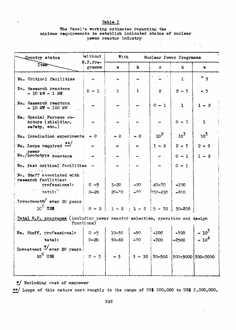
Table IThe Panel's working estimates regarding, the
minimum requirements to establish indicated status of nuclearpower reactor industry
2guntry status without With Nuclear Power Programme;?ï--»_ H . r . rro-Iteflr -— - ___
No. Critic?! facilitiesNo. Research reactors
~ 10 kïï - 1 MWNo. Research reactors
« 10 MW - 100 MWNo. Special Purpose re-
actors ( shielding,safety, etc.)
-
0-1
a
-
•j•*•!
-
No. Irradiation experiments « 0**/; Ne. Loops required — '
t power • -. . : .: No. /prototype reactors:
-
No. fast critical facilities -No. S&aff associated withresearch facilities?
professional:"' total»"" •
Investment» over 20 years1C6 US$
o -50-20
0-2
-
b
-
1
i
c i d-
2 i
0-1
-I »
~ 0 - 0- -
102
1-2- 'j
M» --. ^^
I
I
1
5-20 «20 /JO-7020-C0 ~^n 050-450
|1-2 [ 1 - 2 5-30
1
2-3
1
0-1
105
2-30-10-1
-100
e
•3
- 5
1 - 2
1
105
2-51-2
«600 j
50-200 j.jP pjpo raggae (including power reactor selection, operation and design
functions)! No. Staff, professional* 0 -5
total » 0-20*/Investment — ' over 20 years
| 106 US* 0-3
!
10-3030-60
- 3
"«50 i ~ioo~70 ! ~?00
j3 - 50 | 50-300
«500-2500
300-5000
tj*« 10'
- 104
500-5000
£/ Excluding cost of manpower**/ Loops of this nature cost roughly in the range of US$ 200,000 to US$ 2,000,000.
396

Table II
The following- list of possible research topics is selected from thepapers presented to the Panel and is here classified according to theindicated three functions.l) Familiarization with the special requirements of nuclear
technology and determination of necessary data»a) Measurement of reactor parameters such as flux spectrum,
cross-sections, nuclear interactions, temperature and voidcoefficients, reactivity.
b) Shielding experimentsc) Core lattices studiesd) Approach to criticality and procedurese) Instrumentation for measurements control and recording.
Its limitations and possible further development.f) Operation of the reactorg) Safety procedures
Verification of nuclear calculationsRadiation monitoringHandling of fuel and radioactive materials and effluentsReactor chemistry
1) Familiarization with in and out core fuel managementm) Familiarization with safeguards requirements
2) Work in support of a nuclear power programme (however far aheadthat might be)•a) Development of fuelsbj Development of canning and pressure vessel materialsc) Development of instrumentation for control, fuel failure
and recordingd) Heat transfer and thermo-hydraulic studiese) Effects of fast neutron and fission-fragment damage on
creep behaviourf) Effects of reactor irradiation on corrosion, considering
both, the physics of the solid and the chemistry of thecoolant fluid.
g) Mechanisms for mass transfer of activated corrosion productsin the coolant
h) Effects of very high vacancy concentrations, the formation ofvoids and bubbles, and the consequences of these defects onthe materials' properties
i) Nature of irradiation damage in various graphites as a functionof temperature
j) Performance and liability tests of materials, componentsand equipment in the nuclear environment
k) Verification of hazard analysis1) Items already noted under l)
3) Other areas not forming part of l) or 2) but which will or canresult in either national benefit or income to the institutionwhich will possess the required reactor.Production of isotopesNeutron radiographyActivation analysisBeam experiments
397
ANNEX
LIST OF PARTICI PANTS
Scientific Secretaries t
H. Gonzalez-MontesB. Kolbasov
ArgentinaMr. J. Cosentino
Austria - \Mr. A. Burtschsr
Belgium "- -;;"Mr. L. Danguy
Mr. G Stiennon
Mr. F.R.Vanmassenhove
BulgariaMr. R. Georgiev
a/o Group of Argentinian ExpertsTS No. 112, A-Atucha
J3FÏÏ Proyecto CN/Atucha.Gerente de EnergiaAvenida Libertador 8250Buenos AiresArgentina
Head of ASTBA Reactor Centre SelbersdorfSeibersdorf, N.b.Austria
ProfessorFaculté polytechnique de MonsCentre de recherches nucléairesRue BrissalotMons, 7800Directeur Adjoint - . ,Head of the Reactor DivisionCommissariat à l'énergie nucléaire200 BoeretangMol-DonkProfessorRyksuniversiteit of GentJ. Plateaustr. 229000 - Gent
Chief EngineerNuclear Power DepartmentMinistry of EnergeticsDondukovstr. 2Sofia
399
CanadaMr. A.J. Mooradian
Mr. J.A.L. Robertson
Vice-Présidentin charge of Whiteshell NuclearResearch Establishment
Atomic Energy of Canada LimitedPinawa, ManitobaDirector of Fuels and Materials DivisionAtonrc Energy of Canada LimitedChalk River LaboratoriesChalk River, Ontario
FinlandMr. A. Palmgren
FranceMr. J. Berger
Mr. M. Seguin
Head of Research DivisionVice-Director of Reactor Lab.Technical UniversityDepartment of Technical PhysicsOtaniemi (Helsinki)
Adjoint au chef de la Section d*etudeet de développement des techniquesd'irradiation service des Pils de Grenoble
C.E.Sf. de GrenobleCedex 8538-Grenoble-GareChef de la Section de Préparation etd'Exploitation des Irradiations
C.E.ÏÏ. de GrenobleCedex 8538-Grenoble-Gare
GreeceMr. N. Chrysochoides
IndiaMr. S.M. Sundaram
Director, Reactor DepartmentGreek Atomic Energy CommissionNuclear Research Center "Democritos"Agia ParaskeviAthens
Head, Bhabha Atomic Research CentreReactor Operations DivisionTrombay, Bombay-85 AS
400
NetherlandsMr. H.H. Kleijn
Mr. J.J.M. Snepvangers
RomaniaMr. P. Popa
Professor in Reactor PhysicsUniversity of DelftInteruniversitair Reactor InstituutBerlageweg 15DelftStichting Reactor Centrum tfederlandPatten (H.H.)
Chercheor a 1*Institute de PhysiqueAtomiquej expert dans le ComitédTEtat pour l'Energie Nucléaire
Le Comité d'Etat pour l'Energie nucléaireBd. Ilie Pintilie 3-5» Sector 1Bucarest
Mr. J.Montes Ponce de Léon
SwedenMr. K. Saltvedt
U.A.R.Mr. M.P. El-Fouly
Jefe Seocion Reactores de PiscinaJunta de Energia NuclearCiudad ïïniveraitariaMadrid
Head of Section for Operation ofResearoh Reactors
AB AtomenergiStudsvik PackS-611 01 SfykSping
Atomic Energy EstablishmentCairo
U.K.Mr. L.M. Davies
Mr. J. Kirk
Mr. P. Taylor
MetallurgistUKAEAHarwell, Didcot., Berks.Operations Manager» DPRDounreay Experimental ReactorEstablishment
Thurso, Caithness, ScotlandGroup Leader for Irradiation Experiments
in Design DepartmentUKAEA B 521Harwell, Didcot., Berks.
401
Dr. B.O. Wade
U.S.A.Mr. P.U. Fisher
Mr. D.H. Lennoz
EURATOMMr. H.J. Ehringer
Group Leader, Research Reactor Physiosand Design» Computing and Data Pro-cessing Systems
Gulf General Atomic EuropeWeinbergstrasse 1098006 Zurich, SwitzerlandManager, Systems Management and EvaluationSection
LMFBR Program OfficeArgonne National Laboratory9700 South Cass AvenueArgonne, Illinois 60439
DirectorCentre de Investigaciones tfucleares (Proyecto)Av. J. Herrera y Reissig 565Montevideo
Head of the J>epartment for ReactorPhysics and Dynamics
Federal Nuclear Energy CommissionInstitute Boris KidricP.O.Box 522Belgrade
Chef de division "Réacteurs à haut flux"Commission des Communautés Européennes200 rue de la LoiBrussels 4» Belgium
402
Uruguay
Mr. J. Spitalnik
Yugoslavia
Mr. N. Raisift
Related Documents