Engineering & Expertise Designing Pump Sumps FORMED SUCTION INTAKE

Welcome message from author
This document is posted to help you gain knowledge. Please leave a comment to let me know what you think about it! Share it to your friends and learn new things together.
Transcript
Engineering & Expertise Designing Pump SumpsFormED Suction intakE

Theo
retic
al a
naly
sis
Products
Reference installations
Physical tests
E n g i n e e r i n g & E x p e r t i s e
Investment
UnplannedOperational
2
Total solution engineering increases operational efficiency
EnginEEring & ExpErTisE
introduction
The primary function of a propeller pump intake is to provide stable, even, and rotation free flow to the pump. A good intake design will enable optimum pump performance under all operating conditions. Good intake design also eliminates hydraulic phenomena and other conditions, such as sedimentation and accumulation of floating debris, that can have a negative impact on pump performance. In addition, the sump should be kept compact and straightforward to reduce the installation footprint and minimize construction costs.
Determining the optimal pump intake therefore requires engineering and expertise. We will present guidance for the design of pump intakes for propeller pumps. Methods and procedures are given for handling various inflow conditions, preventing solids buildup, and using specially developed formed suction intakes in order to achieve an efficient, compact propeller sump design in very limited space.
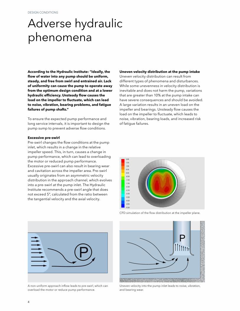
Achieving lowest total cost of ownership
Investment costsCosts associated with design, excavation, civil work, product purchases, installation, and commissioning.
Operational costsOver time, energy usage and maintenance costs are the largest contributors to the total cost of ownership.
Unplanned costsWhen things go wrong, such as pump failures stemming from problematic station design, costs can sky rocket. Unexpected downtime can cause sewer backups, overflows, basement flooding, and untreated effluent. On top of that, you have to repair pumps and take corrective measures regarding the station design.
When providing pumping solutions, Flygt prefers to take the total cost of ownership into consideration.
Engineering & ExpertiseThanks to our engineering expertise, we can lower your total cost of ownership. We can analyze your system using state-of-the-art computational programs. We can test your pump station using scale models if required. We can also provide you with reference installations that are similar to your project. All of this together with our premium products provides you with an optimized design.
3
Minimizing station footprint
inTrODUCTiOn
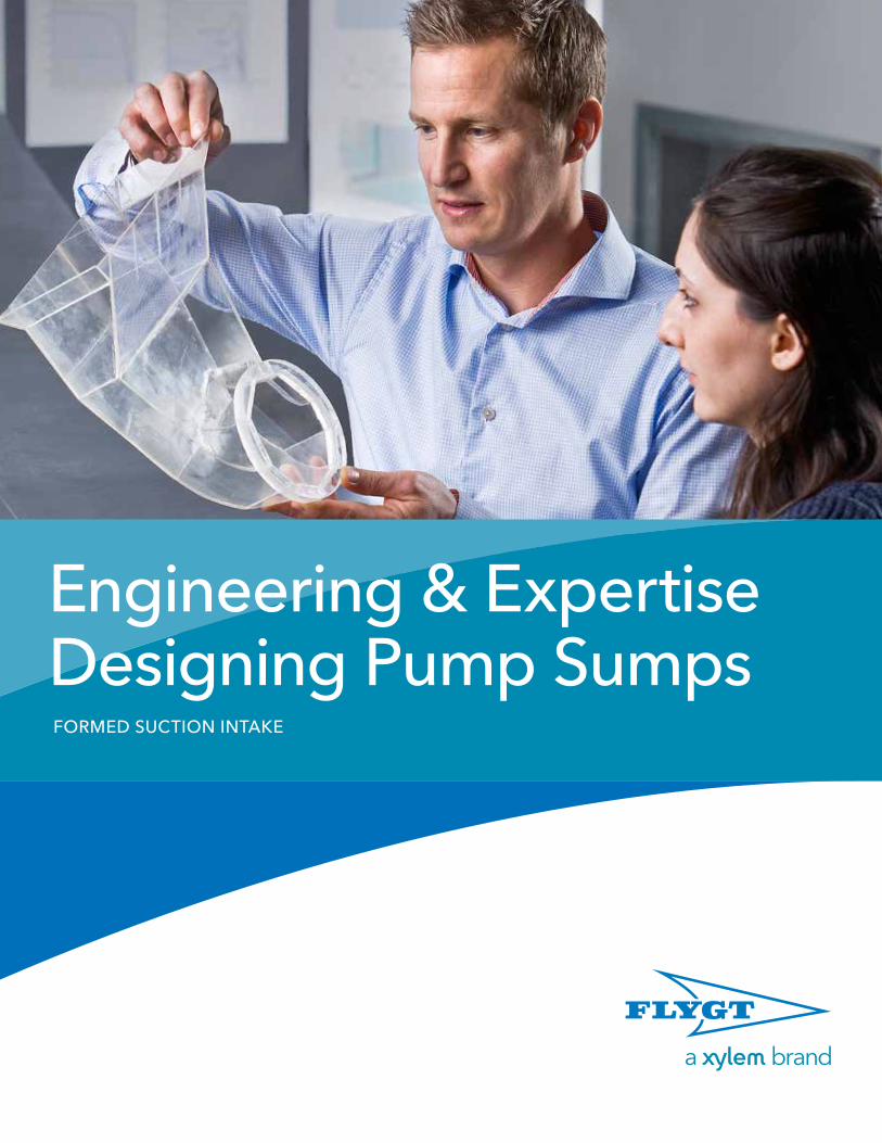
Achieving lowest total cost of ownershipThe Flygt Fsi is designed to reduce overall investment costs by reducing the propeller pump station footprint to an absolute minimum. This pump intake device ensures highly reliable operation and therefore lowers the risk of downtime. it combines the ease of fabrication with relatively small dimensions to deliver optimal hydraulic performance, which contributes to equipment longevity and the lowest total cost of ownership.
The Flygt Formed suction intake (Fsi) is an inlet device that provides optimal inflow to the propeller pump by gradually accelerating and redirecting the flow toward the pump inlet. its primary function is to condition the incoming flow into a uniform profile and redirect the flow.
The Flygt Fsi is ideal for use:
•Whenadverseinflowconditionsexist•Whenspaceavailableforthepumpstationis
limited• Forintakeswithperpendicularorskewedinflows• Forcriticalinstallationsandcontinuousoperation
By providing a reliable pump intake in limited space, the Flygt Fsi is able to achieve a more economical pump station solution with a smaller footprint and better hydraulic performance than with standard inlet devices.
4
Adverse hydraulic phenomena
DEsign COnDiTiOns
To ensure the expected pump performance and long service intervals, it is important to design the pump sump to prevent adverse flow conditions.
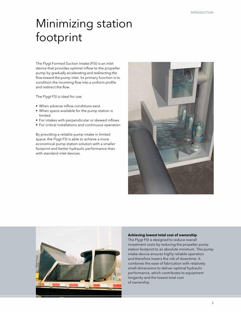
Excessive pre-swirlpre-swirl changes the flow conditions at the pump inlet, which results in a change in the relative impeller speed. This, in turn, causes a change in pump performance, which can lead to overloading the motor or reduced pump performance. Excessive pre-swirl can also result in bearing wear and cavitation across the impeller area. pre-swirl usually originates from an asymmetric velocity distribution in the approach channel, which evolves into a pre-swirl at the pump inlet. The Hydraulic institute recommends a pre-swirl angle that does not exceed 5°, calculated from the ratio between the tangential velocity and the axial velocity.
According to the Hydraulic Institute: “Ideally, the flow of water into any pump should be uniform, steady, and free from swirl and entrained air. Lack of uniformity can cause the pump to operate away from the optimum design condition and at a lower hydraulic efficiency. Unsteady flow causes the load on the impeller to fluctuate, which can lead to noise, vibration, bearing problems, and fatigue failures of pump shafts.”
Uneven velocity distribution at the pump intakeUneven velocity distribution can result from different types of phenomena and disturbances. While some unevenness in velocity distribution is inevitable and does not harm the pump, variations that are greater than 10% at the pump intake can have severe consequences and should be avoided. A large variation results in an uneven load on the impeller and bearings. Unsteady flow causes the load on the impeller to fluctuate, which leads to noise, vibration, bearing loads, and increased risk of fatigue failures.
A non-uniform approach inflow leads to pre-swirl, which can overload the motor or reduce pump performance.
Uneven velocity into the pump inlet leads to noise, vibration, and bearing wear.
CFD simulation of the flow distribution at the impeller plane.

5
Entrained air can cause reduction in discharge and loss of efficiency.
strong submerged vortex.
strong surface vortex with an air core will result in cavitation, uneven load, noise, and vibration.
Entrained air and vortex shown in scale model test.
Entrained airit is widely known that even minor air entrainment, of some 3.4% of the volume, will lead to a clear reduction in pump performance and loss of efficiency; the severity depends upon the quantity of air entrained and the pump type. The expansion of ingested air bubbles within the impeller may result in mechanical imbalance, vibration, and acceleration of mechanical wear. normal design practices recommend the exclusion of any air entrainment in the approach flow to the pump intake. in addition, entrained air leads to increased corrosion.
While air bubbles may be present in the liquid for a variety of reasons, their presence is usually due to cascading of the water as it enters the sump from a weir, culvert, or incoming pipe located above the surface water level in the sump.
VorticesUnlike excessive pre-swirl, vortices appear locally with higher intensity and are a major hindrance to proper pump operation, resulting in cavitation, uneven load, noise, and vibration. There are several different types of vortices.
The most commonly known type is the free surface vortex, which can have varying degrees of intensity – from weak surface vortices to fully developed vortices with a continuous air core that extends from the surface into the pump.
Less well known, but just as common, is the vortex that originates under the surface from the sump bottom, walls, or between two pumps, and extends to the pump inlet. This type of vortex can achieve high rotational speeds with high subpressures and cavitations.

6
Achieving uniform inflow
pUMp sTATiOn DEsign
To achieve homogeneous flow into the propeller pump, there are two major types of pump station designs: the open sump intake and the formed suction intake.
Open sump intake designThe most commonly used approach is the open sump intake design with open channels into the pumps. This design is the most sensitive to non-uniform approach flows; therefore, it requires the use of a longer forebay and longer dividing walls between the individual pump bays than the formed suction intake design.
To achieve a steady, uniform flow toward each pump, the flow into the pump should be parallel to the pump channel. ideally, the inlet to the sump is placed directly opposite the pumps and is directed toward these, but in many cases this is not possible due to angled inflow or lack of space.
Open sump intake design includes devices such as splitters and divider plates that alleviate the effects of minor asymmetries in the approach flow.
pump station with open channels to the pumps.
schematic plan of a pump station with open channels to the pumps.
Cross-section of a pump station with open channels to the pumps.

7
Formed suction intake designin situations with adverse flow conditions or limited space, the use of a formed suction intake design may be more appropriate. its main function is to normalize the flow by means of acceleration and redirect the flow vertically into the pump inlet.
The formed suction intake design can be constructed either of concrete or steel. The intake reduces disturbances and swirl in the approach flow. The inclined front wall is designed to prevent stagnation of the surface flow. The geometrical features of this intake provide smooth acceleration and smooth turns as the flow enters the pump. This design is recommended for stations with multiple pumps with various operating conditions.
Formed suction intake design is the least sensitive to disturbances in the approach flow that can result from:
• Divergingflow• Flowthatmustberedirectedintheforebay• Singlepumpoperationatpartialload
schematic plan of a formed suction intake with side inlet. Cross-section of a formed suction intake.
pump station with formed suction intake in concrete.
~8
0%
8
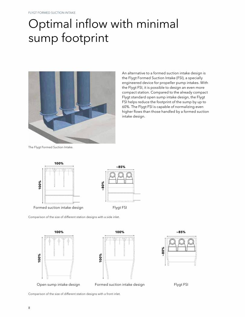
Comparison of the size of different station designs with a front inlet.
Comparison of the size of different station designs with a side inlet.
Formed suction intake design
Open sump intake design Flygt FsiFormed suction intake design
Optimal inflow with minimal sump footprint
FLygT FOrMED sUCTiOn inTAkE
An alternative to a formed suction intake design is the Flygt Formed suction intake (Fsi), a specially engineered device for propeller pump intakes. With the Flygt Fsi, it is possible to design an even more compact station. Compared to the already compact Flygt standard open sump intake design, the Flygt Fsi helps reduce the footprint of the sump by up to 60%. The Flygt Fsi is capable of normalizing even higher flows than those handled by a formed suction intake design.
The Flygt Formed suction intake.
Flygt Fsi
100%~85%
10
0%
100% 100%
10
0%
10
0%
~85%
~8
0%
9
Free standing.
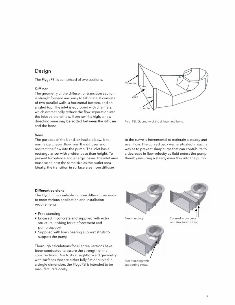
Flygt Fsi: geometry of the diffuser and bend.
Free standing with supporting struts.
Encased in concrete with structural ribbing.
Design
Different versionsThe Flygt Fsi is available in three different versions to meet various application and installation requirements.
• Freestanding• Encasedinconcreteandsuppliedwithextra
structural ribbing for reinforcement and pump support
• Suppliedwithload-bearingsupportstrutstosupport the pump
Thorough calculations for all three versions have been conducted to assure the strength of the constructions. Due to its straightforward geometry with surfaces that are either fully flat or curved in a single dimension, the Flygt Fsi is intended to be manufactured locally.
The Flygt Fsi is comprised of two sections.
DiffuserThe geometry of the diffuser, or transition section, is straightforward and easy to fabricate. it consists of two parallel walls, a horizontal bottom, and an angled top. The inlet is equipped with chamfers, which dramatically reduce the flow separation into the inlet at lateral flow. if pre-swirl is high, a flow directing vane may be added between the diffuser and the bend.
BendThe purpose of the bend, or intake elbow, is to normalize uneven flow from the diffuser and redirect the flow into the pump. The inlet has a rectangular cut with a wider base than height. To prevent turbulence and energy losses, the inlet area must be at least the same size as the outlet area. ideally, the transition in surface area from diffuser
to the curve is incremental to maintain a steady and even flow. The curved back wall is situated in such a way as to prevent sharp turns that can contribute to a decrease in flow velocity as fluid enters the pump, thereby ensuring a steady even flow into the pump.
Chamfer
Chamfer
Vane
BA
+15%
–15%
10
FLygT FOrMED sUCTiOn inTAkE
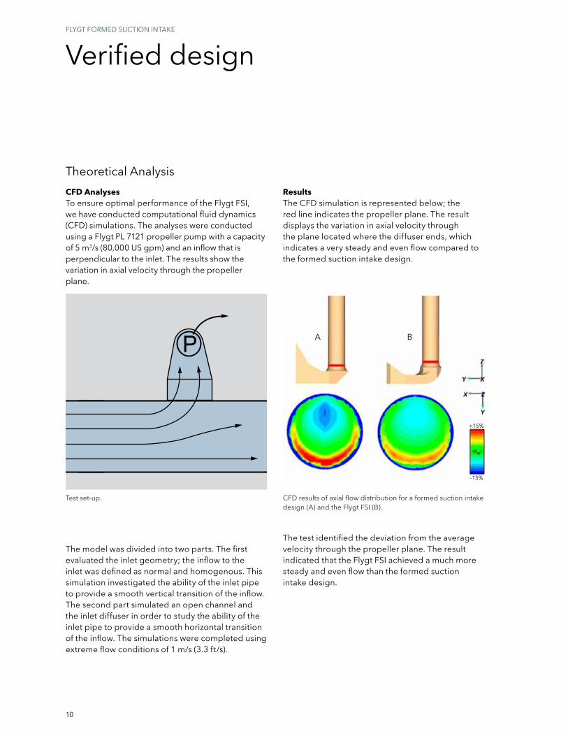
CFD results of axial flow distribution for a formed suction intake design (A) and the Flygt Fsi (B).
Test set-up.
CFD AnalysesTo ensure optimal performance of the Flygt Fsi, we have conducted computational fluid dynamics (CFD) simulations. The analyses were conducted using a Flygt pL 7121 propeller pump with a capacity of 5 m3/s (80,000 Us gpm) and an inflow that is perpendicular to the inlet. The results show the variation in axial velocity through the propeller plane.
Theoretical Analysis
The model was divided into two parts. The first evaluated the inlet geometry; the inflow to the inlet was defined as normal and homogenous. This simulation investigated the ability of the inlet pipe to provide a smooth vertical transition of the inflow. The second part simulated an open channel and the inlet diffuser in order to study the ability of the inlet pipe to provide a smooth horizontal transition of the inflow. The simulations were completed using extreme flow conditions of 1 m/s (3.3 ft/s).
ResultsThe CFD simulation is represented below; the red line indicates the propeller plane. The result displays the variation in axial velocity through the plane located where the diffuser ends, which indicates a very steady and even flow compared to the formed suction intake design.
The test identified the deviation from the average velocity through the propeller plane. The result indicated that the Flygt Fsi achieved a much more steady and even flow than the formed suction intake design.
Verified design
11
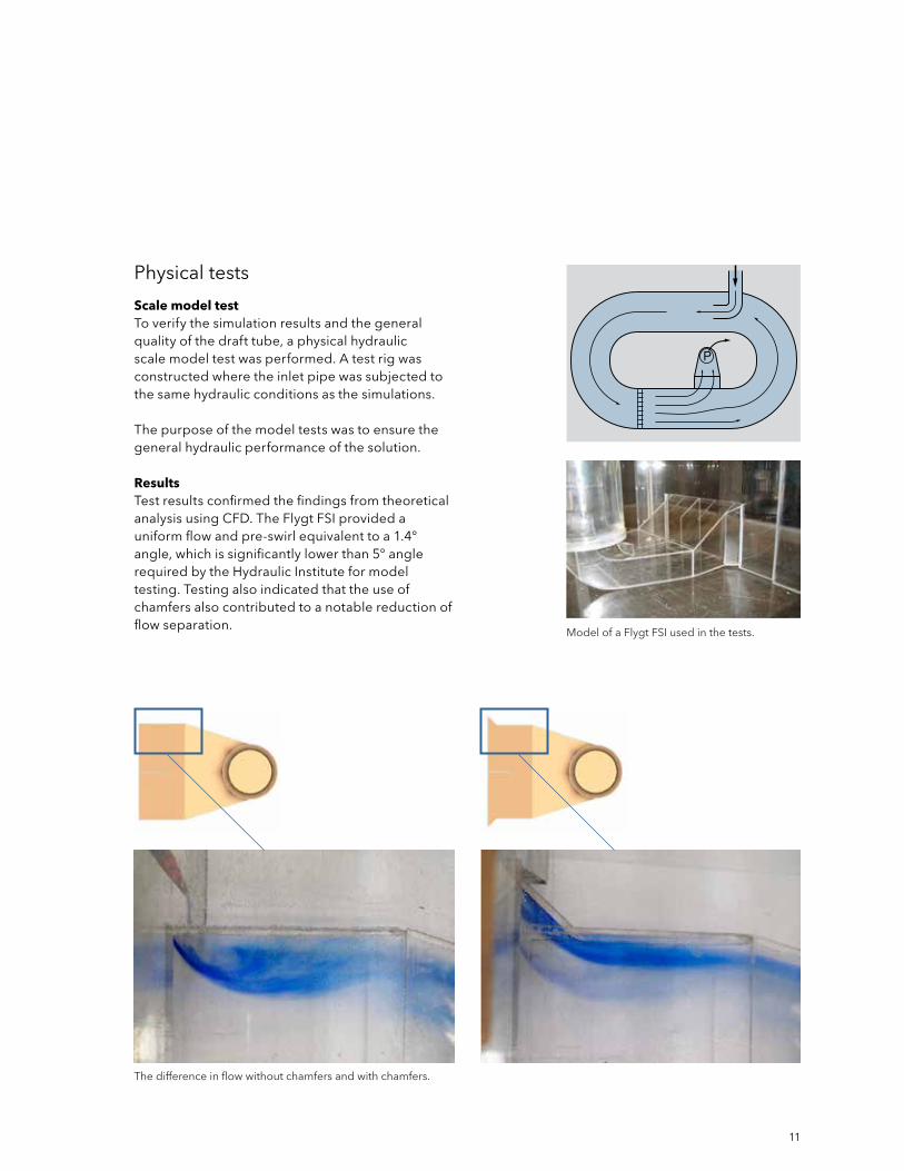
The difference in flow without chamfers and with chamfers.
Model of a Flygt Fsi used in the tests.
physical tests
Scale model testTo verify the simulation results and the general quality of the draft tube, a physical hydraulic scale model test was performed. A test rig was constructed where the inlet pipe was subjected to the same hydraulic conditions as the simulations.
The purpose of the model tests was to ensure the general hydraulic performance of the solution.
ResultsTest results confirmed the findings from theoretical analysis using CFD. The Flygt Fsi provided a uniform flow and pre-swirl equivalent to a 1.4° angle, which is significantly lower than 5° angle required by the Hydraulic institute for model testing. Testing also indicated that the use of chamfers also contributed to a notable reduction of flow separation.

25.9
671 m²
274 m²
17.7
15.5
25.9
12
proven worldwide
Flygt has designed pump stations for thousands of installations around the world. Engineering expertise and years of experience have resulted in the success of these installations. Three such installations are described below.
rEFErEnCE insTALLATiOns
United States: Combined stormwater and sewage pump station
ChallengeTo develop a combined stormwater and sewage pump station at the lowest possible cost.
SolutionThe station was designed with three Flygt Cp 3501 and six Flygt pL 7121 pumps. The use of a Flygt Fsi reduced the pump station footprint by nearly 60% and lowered the construction costs by more than 10%. This ensures reliable pumping using the smallest possible footprint.
United States: Stormwater pump station
ChallengeOne major Midwestern city’s challenge was the placement of a new stormwater pump station in a 10 m x 5 m (32 × 18 ft) area between two roads and a hotel. Close proximity to three rivers, snow melting during the springtime, and heavy rainfall during the summer posed flooding risks to the area.
SolutionA compact stormwater station was designed with excellent hydraulics within the limited space using Flygt propeller pumps and Flygt Fsis. Each pump is rated 280 Hp and designed to pump 2 m3/s (31,600 Us gpm) at 7 m (22 ft) TDH. Thanks to the use of the Flygt Fsis, the station was able to handle 22 cm (9 in.) of rainfall in a single day. The station is so compact that it can accommodate an additional pump should expansion be necessary in the future.

13
China: Circular sewage and stormwater pump station
ChallengeA large combined sewage and stormwater station will be built in one of the largest cities in the world. The flow is high, the head is fairly low, and the footprint is limited.
SolutionUsing Flygt submersible pumps in a circular wet well design, the footprint of the installation was kept to a minimum. For the flow and head conditions of the stormwater, Flygt propeller pumps were the most suitable. A circular sump is generally not preferred for propeller pumps due to the adverse flow conditions that can occur. To avoid such conditions, Flygt Fsis were successfully used in order to achieve uniform inflow to the pumps.

14
Engineering & ExpertisesErViCEs AnD sUppOrT
Theoretical analysis
Design tools
When you design pump stations, we can offer advanced engineering tools to generate sump designs. Our design recommendations give you essential information regarding dimensions and layout. in short, we assist you every step of the way to make sure you optimize performance and achieve energy-efficient operations.
To ensure reliable and highly efficient operation, we offer comprehensive support and service for pump station design, system analysis, installation, commissioning, operation, and maintenance.
Computational fluid dynamics (CFD) can provide far more detailed information about the flow field in a fraction of the time required to get the same information through physical hydraulic scale model testing. Using CFD in combination with computer-aided design (CAD) tools, it is possible to obtain a more efficient method of numerical simulation for pump station design.
To obtain a reliable, energy-efficient pumping system, it is important to analyze all modes of operation. To analyze the transient effects at pump start and stop with respect to flow and head, as well as the electrical parameters such as current and torque, it is also important to have an accurate mathematical description of the pump and motor, which is gained, in part, from extensive testing in our laboratories.

Theo
retic
al a
naly
sis
Products
Reference installations
Physical tests
E n g i n e e r i n g & E x p e r t i s e
15
physical testing reference installations
physical hydraulic scale model testing can provide reliable, cost-effective solutions to complex hydraulic problems. This is particularly true for pump stations in which the geometry departs from recommended standards or where no prior experience with the application exists. scale model testing can also be employed to identify solutions for existing installations and has proven to be a far less expensive way to determine the viability of possible solutions than through trial and error at full scale.
When our standard design recommendations are not met, we can assist in determining the need for physical testing as well as planning and arranging the testing and evaluating the results.
We have conducted system analysis and designed pump stations for thousands of installations around the world. Engineering expertise and years of experience gained from the design and operation of these installations have been a critical success factor when analyzing, testing, and commissioning new pump installations.
Model test photos courtesy of Hydrotec Consultants Ltd.

Xylem |'zīl m|1) The tissue in plants that brings water upward from the roots; 2) a leading global water technology company.
We’re 12,000 people unified in a common purpose: creating innovative solutions to meet our world’s water needs. Developing new technologies that will improve the way water is used, conserved, and re-used in the future is central to our work. We move, treat, analyze, and return water to the environment, and we help people use water efficiently, in their homes, buildings, factories and farms. in more than 150 countries, we have strong, long-standing relationships with customers who know us for our powerful combination of leading product brands and applications expertise, backed by a legacy of innovation.
For more information on how xylem can help you, go to www.xyleminc.com
xylem, inc.14125 south Bridge CircleCharlotte, nC 28273Tel 704.409.9700Fax 704.295.9080855-xyL-H2O1 (855-995-4661)www.xyleminc.com
Flygt is a trademark of xylem inc. or one of its subsidiaries. © 2015 xylem, inc. Apr 2015
e
FB15
9-11
99 •
Fly
gt
Eng
inee
ring
& E
xper
tise
Des
igni
ng P
ump
Sum
ps
Form
ed S
uctio
n In
take
Bro
chur
e •
4/20
15 •
NA
CT
Related Documents