1 GRASP Nora Ayanian University of Pennsylvania Engineering Design Process, Prototyping, & Linkages/Mechanisms SAAST Robotics 2008

Welcome message from author
This document is posted to help you gain knowledge. Please leave a comment to let me know what you think about it! Share it to your friends and learn new things together.
Transcript
1GRASP
Nora Ayanian
University of Pennsylvania
Engineering Design Process, Prototyping, & Linkages/Mechanisms
SAAST Robotics 2008
2GRASP
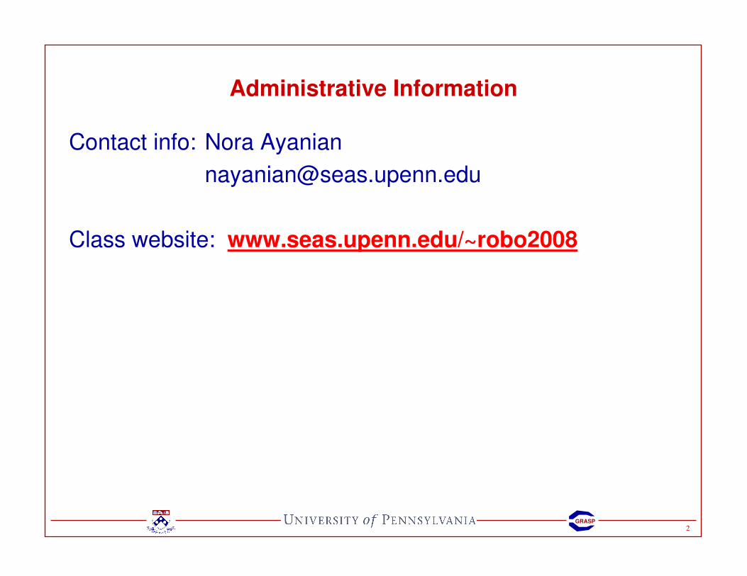
Administrative Information
Contact info: Nora Ayanian
Class website: www.seas.upenn.edu/~robo2008
3GRASP
Engineering Design Process
SAAST Robotics 2008
4GRASP
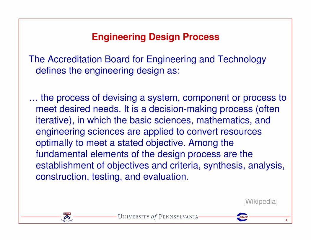
Engineering Design Process
The Accreditation Board for Engineering and Technology defines the engineering design as:
… the process of devising a system, component or process to
meet desired needs. It is a decision-making process (often
iterative), in which the basic sciences, mathematics, and engineering sciences are applied to convert resources
optimally to meet a stated objective. Among the fundamental elements of the design process are the
establishment of objectives and criteria, synthesis, analysis, construction, testing, and evaluation.
[Wikipedia]
5GRASP
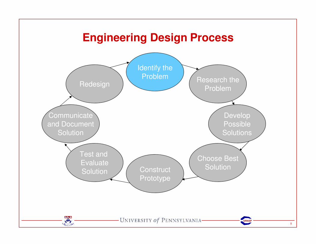
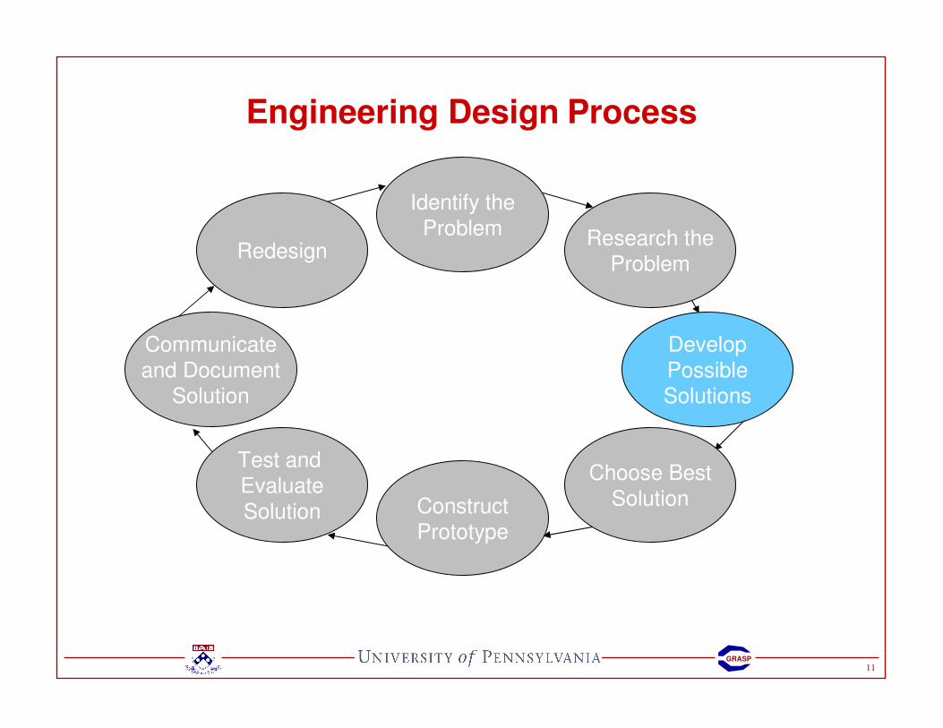
Engineering Design Process
Identify the
Problem Research the
Problem
Develop
Possible
Solutions
Choose Best
SolutionConstruct
Prototype
Test and
Evaluate
Solution
Communicate
and Document
Solution
Redesign
6GRASP
Engineering Design Process
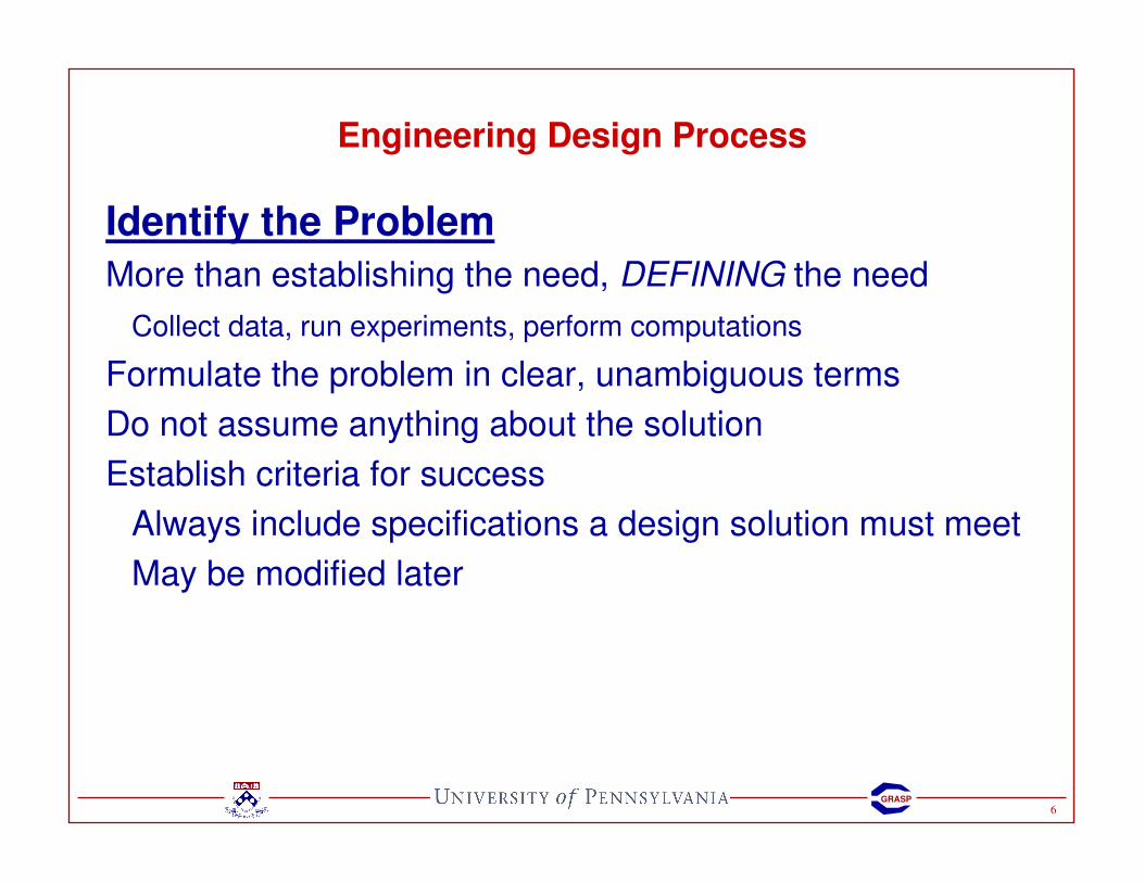
Identify the Problem
More than establishing the need, DEFINING the need
Collect data, run experiments, perform computations
Formulate the problem in clear, unambiguous terms
Do not assume anything about the solution
Establish criteria for success
Always include specifications a design solution must meet
May be modified later

7GRASP
Engineering Design Process
Identify the Problem
What problem are you trying to solve? � Problem Statement
Design a better mousetrap

8GRASP
Engineering Design Process
Identify the Problem
What problem are you trying to solve? � Problem Statement
What tasks or functions are needed to accomplish this?
• The design must be low cost.
• The design should be safe, particularly with small children.
• The design should not be detrimental to the environment.
• The design should be aesthetically pleasing.
• The design should be simple to operate, with minimum human effort.
• The design must be disposable (you don’t reuse the trap).
• The design should not cause undue pain and suffering for the mouse.

9GRASP
Engineering Design Process
Identify the
Problem Research the
Problem
Develop
Possible
Solutions
Choose Best
SolutionConstruct
Prototype
Test and
Evaluate
Solution
Communicate
and Document
Solution
Redesign
10GRASP
Engineering Design Process
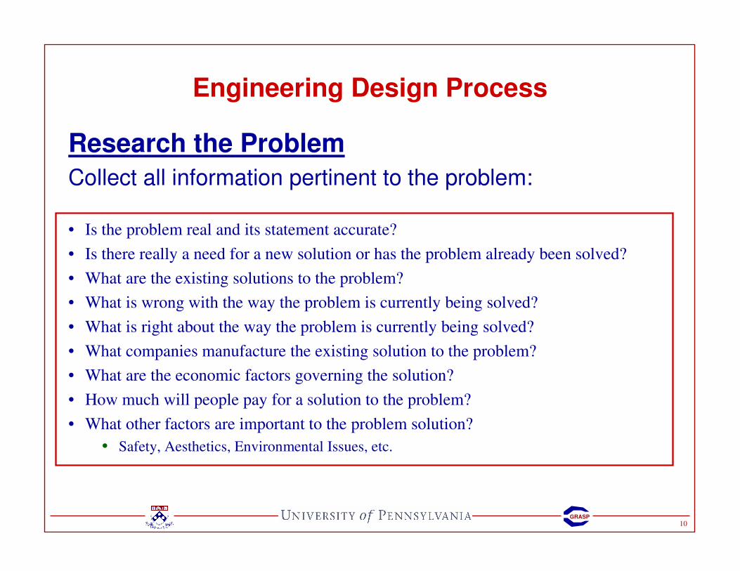
Research the Problem
Collect all information pertinent to the problem:
• Is the problem real and its statement accurate?
• Is there really a need for a new solution or has the problem already been solved?
• What are the existing solutions to the problem?
• What is wrong with the way the problem is currently being solved?
• What is right about the way the problem is currently being solved?
• What companies manufacture the existing solution to the problem?
• What are the economic factors governing the solution?
• How much will people pay for a solution to the problem?
• What other factors are important to the problem solution?
• Safety, Aesthetics, Environmental Issues, etc.
11GRASP
Engineering Design Process
Identify the
Problem Research the
Problem
Develop
Possible
Solutions
Choose Best
SolutionConstruct
Prototype
Test and
Evaluate
Solution
Communicate
and Document
Solution
Redesign

12GRASP
Engineering Design Process
Develop Possible Solutions
Brainstorm
Be creative – think outside the box
Multiple solutions to the same problem
DO NOT RULE OUT ANY SOLUTIONS!!!

13GRASP
Engineering Design Process
Identify the
Problem Research the
Problem
Develop
Possible
Solutions
Choose Best
SolutionConstruct
Prototype
Test and
Evaluate
Solution
Communicate
and Document
Solution
Redesign
14GRASP
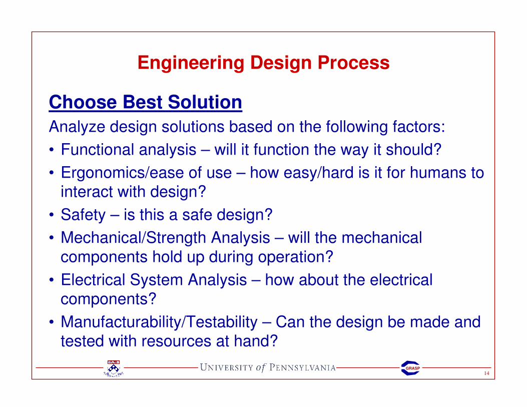
Engineering Design Process
Choose Best Solution
Analyze design solutions based on the following factors:
• Functional analysis – will it function the way it should?
• Ergonomics/ease of use – how easy/hard is it for humans to interact with design?
• Safety – is this a safe design?
• Mechanical/Strength Analysis – will the mechanical
components hold up during operation?
• Electrical System Analysis – how about the electrical components?
• Manufacturability/Testability – Can the design be made and tested with resources at hand?

15GRASP
Engineering Design Process
Identify the
Problem Research the
Problem
Develop
Possible
Solutions
Choose Best
SolutionConstruct
Prototype
Test and
Evaluate
Solution
Communicate
and Document
Solution
Redesign

16GRASP
Engineering Design Process
Construct Prototype• Prototypes may not be fully tested or may not work or
operate as intended
• Purpose: Test the design under solution under real conditions
Test and Evaluate SolutionDesign tests to tell you the following:
• What works?
• What doesn’t work?
• What can be fixed?
• What has to be redesigned?

17GRASP
Engineering Design Process
Identify the
Problem Research the
Problem
Develop
Possible
Solutions
Choose Best
SolutionConstruct
Prototype
Test and
Evaluate
Solution
Communicate
and Document
Solution
Redesign
18GRASP
Engineering Design Process
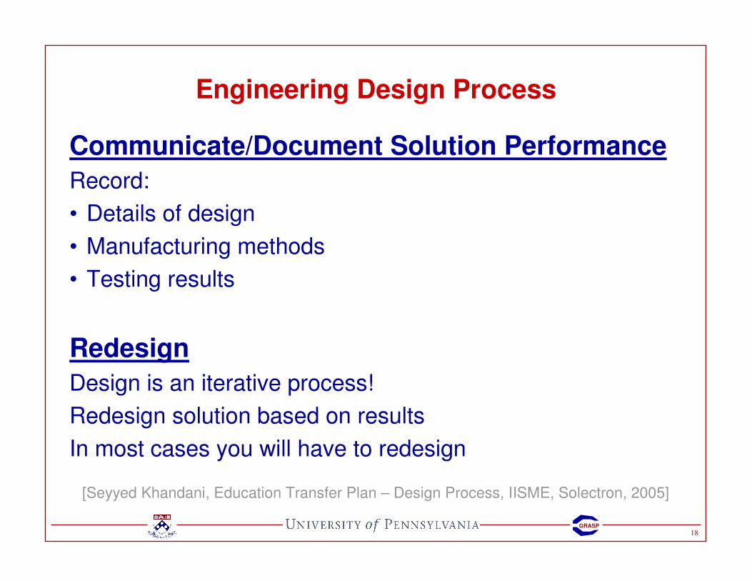
Communicate/Document Solution Performance
Record:
• Details of design
• Manufacturing methods
• Testing results
Redesign
Design is an iterative process!
Redesign solution based on results
In most cases you will have to redesign
[Seyyed Khandani, Education Transfer Plan – Design Process, IISME, Solectron, 2005]
19GRASP
Prototyping
SAAST Robotics 2008

20GRASP
Prototyping: Construction
Adhesives
• Permanent
• Especially good for small or light objects
Threaded fasteners
• Wood screws
• Machine screws
• Self-tapping screws
• Dry-wall screws
• Set screws
21GRASP
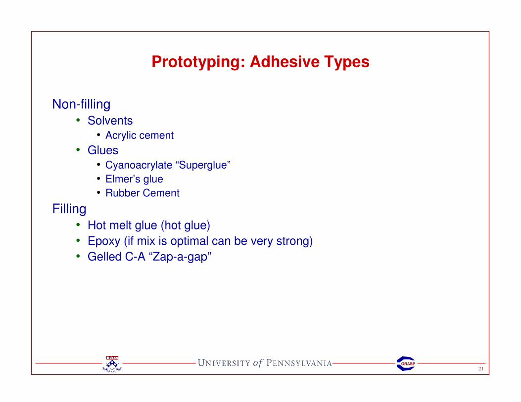
Prototyping: Adhesive Types
Non-filling
• Solvents
• Acrylic cement
• Glues
• Cyanoacrylate “Superglue”
• Elmer’s glue
• Rubber Cement
Filling
• Hot melt glue (hot glue)
• Epoxy (if mix is optimal can be very strong)
• Gelled C-A “Zap-a-gap”

22GRASP
Prototyping: Adhesive Loading
23GRASP
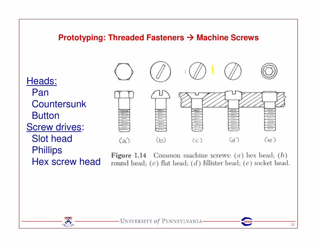
Prototyping: Threaded Fasteners ���� Machine Screws
Heads:Pan
Countersunk
ButtonScrew drives:
Slot headPhillips
Hex screw head
24GRASP
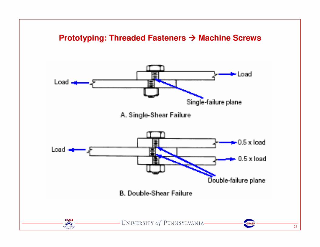
Prototyping: Threaded Fasteners ���� Machine Screws
25GRASP
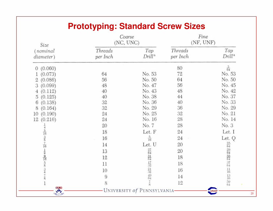
Prototyping: Standard Screw Sizes

26GRASP
Prototyping: Standard Screw Sizes
Most common
2-564-40
6-32¼ - 20
Only use even numbers!
27GRASP
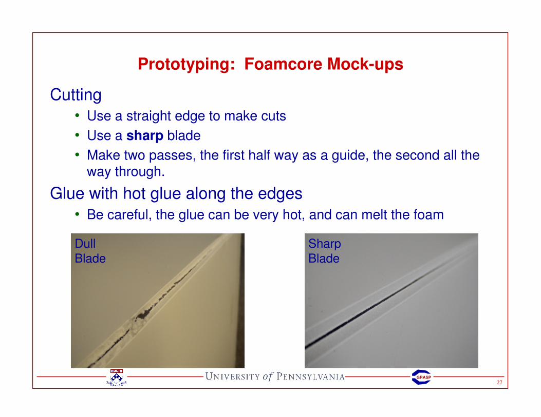
Prototyping: Foamcore Mock-ups
Cutting
• Use a straight edge to make cuts
• Use a sharp blade
• Make two passes, the first half way as a guide, the second all the way through.
Glue with hot glue along the edges
• Be careful, the glue can be very hot, and can melt the foam
Dull
Blade
Sharp
Blade

28GRASP
Prototyping: Foamcore Mock-ups
Clean corners hide the foam:
1. Cut a groove the width of the edge (careful not to cut all the way through)
2. Remove foam, use file if necessary
29GRASP
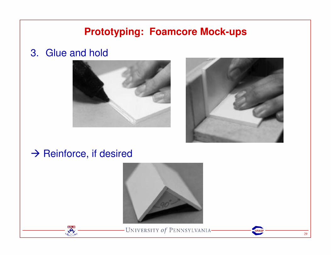
Prototyping: Foamcore Mock-ups
3. Glue and hold
� Reinforce, if desired
30GRASP
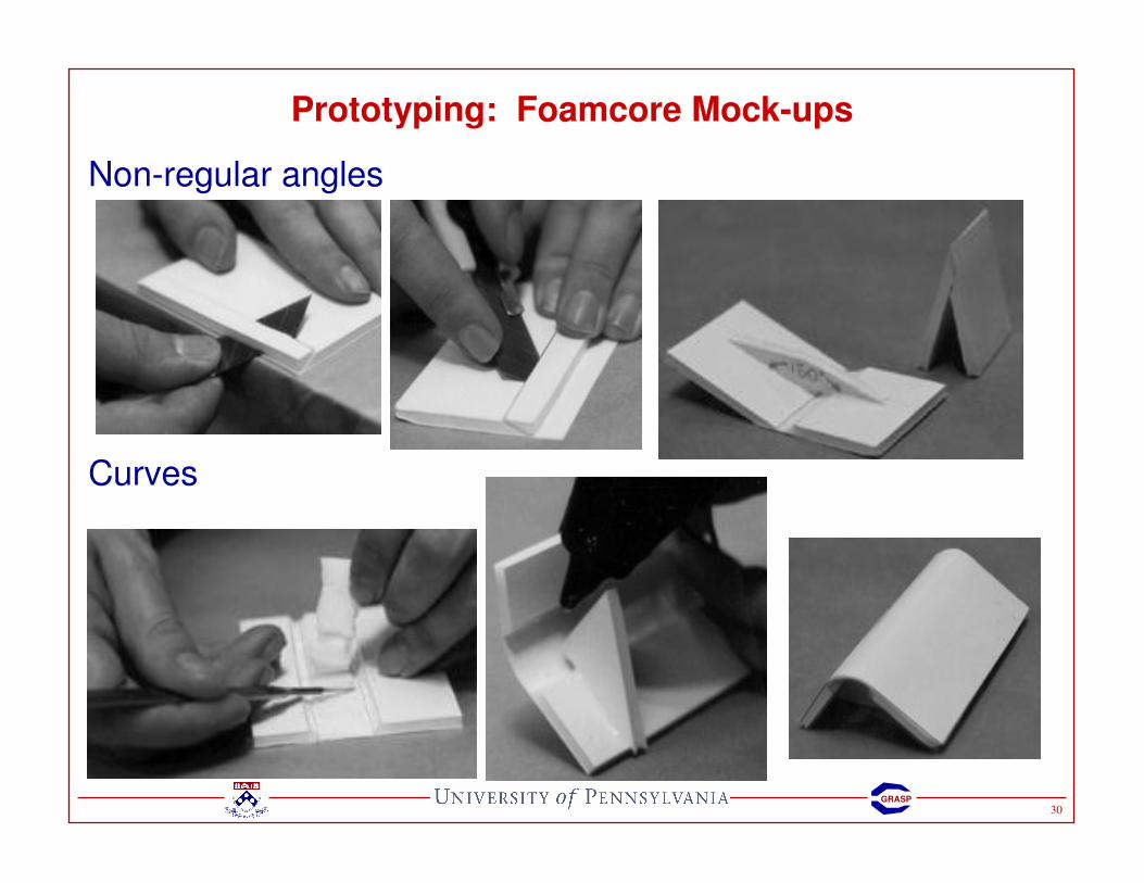
Prototyping: Foamcore Mock-ups
Non-regular angles
Curves

31GRASP
Prototyping: Foamcore Mock-ups ���� Paper Flexure joints
Pros
• Quick and easy to prototype
• Works well with small, light forces
Cons
• Not precise (slop in system)
• Short life (fatigue failure)
• Joint limits
32GRASP
Prototyping: Laser Cutting
• Cuts planar (2D parts) from CAD file
• Plotter with laser instead of pen
• Used mostly with soft materials such as plastics (plexi-glass, acrylic) and wood
• Does not cut metal
• Hints for use:
• Don’t assume thickness of stock material – measure it
• 0.25” � 0.21”
• Don’t assume laser will cut slot of exact thickness. Laser width is about 0.007”
• Laser diameter depends on focus. Cuts from laser will not be perfectly vertical but close to it. Depends on focal length of lens.
• Bond parts together with acrylic cement in joints

33GRASP
Mechanisms/Linkages
SAAST Robotics 2008

34GRASP
Mechanisms/Linkages: Degrees of Freedom (DOF)
The number of independent movements of a rigid body or system
How many DOF for an object on a plane?
How many DOF for an object in space?
35GRASP
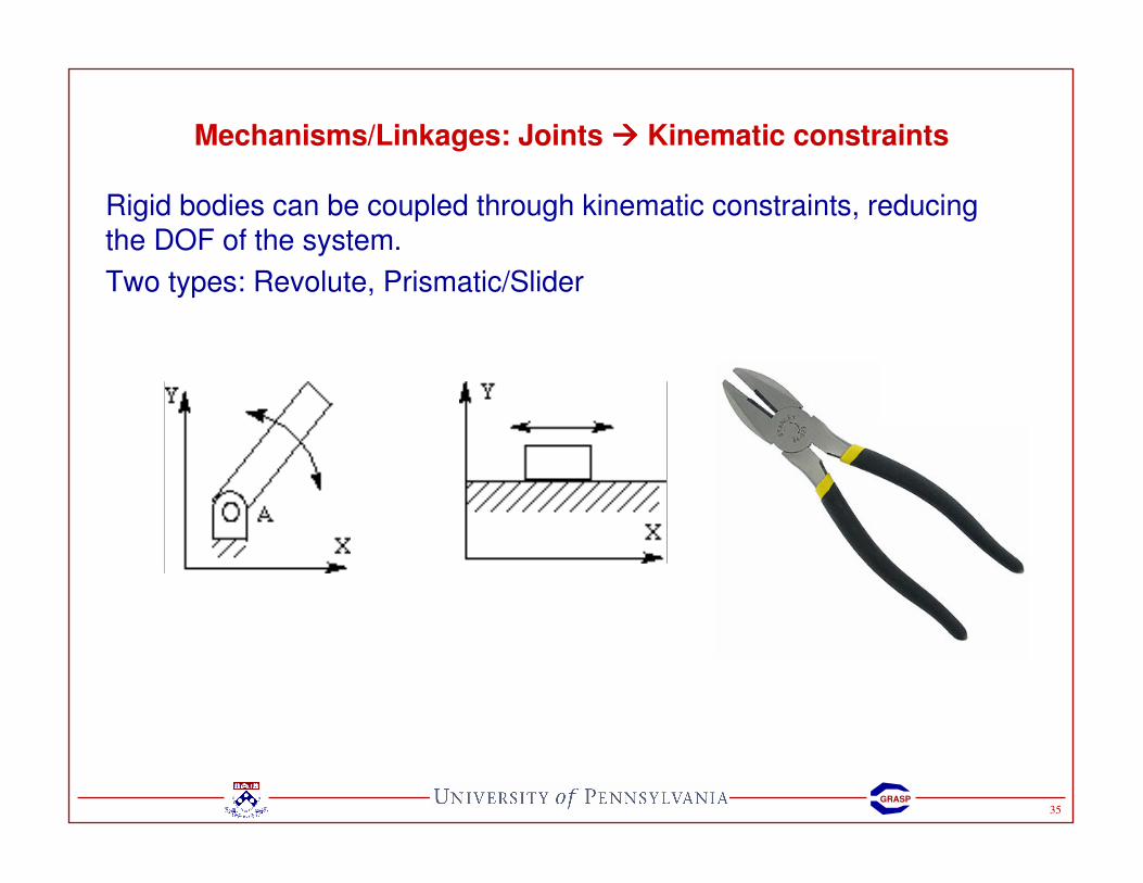
Mechanisms/Linkages: Joints ���� Kinematic constraints
Rigid bodies can be coupled through kinematic constraints, reducing the DOF of the system.
Two types: Revolute, Prismatic/Slider
36GRASP
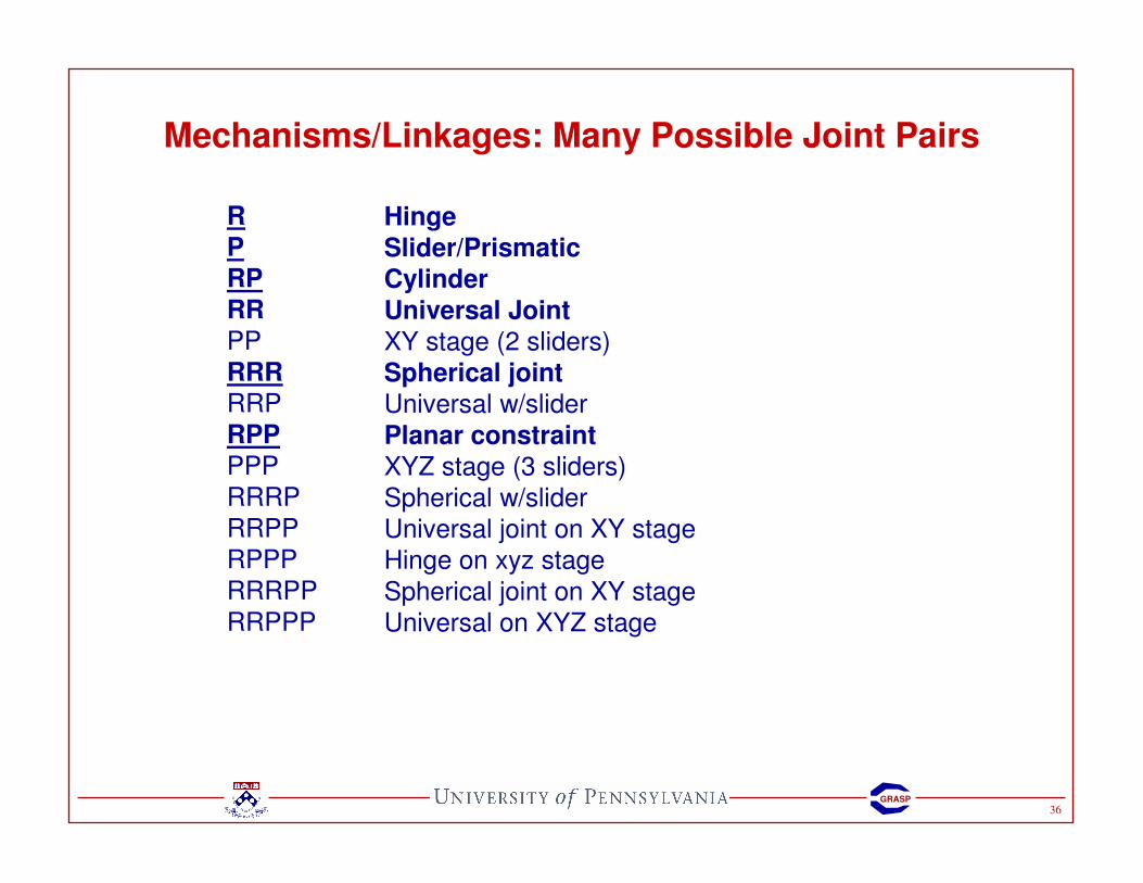
Mechanisms/Linkages: Many Possible Joint Pairs
RPRP
RR
PP
RRRRRP
RPP
PPP
RRRP
RRPP
RPPP
RRRPP
RRPPP
Hinge
Slider/PrismaticCylinder
Universal Joint
XY stage (2 sliders)
Spherical joint
Universal w/slider
Planar constraint
XYZ stage (3 sliders)
Spherical w/slider
Universal joint on XY stage
Hinge on xyz stage
Spherical joint on XY stage
Universal on XYZ stage
37GRASP
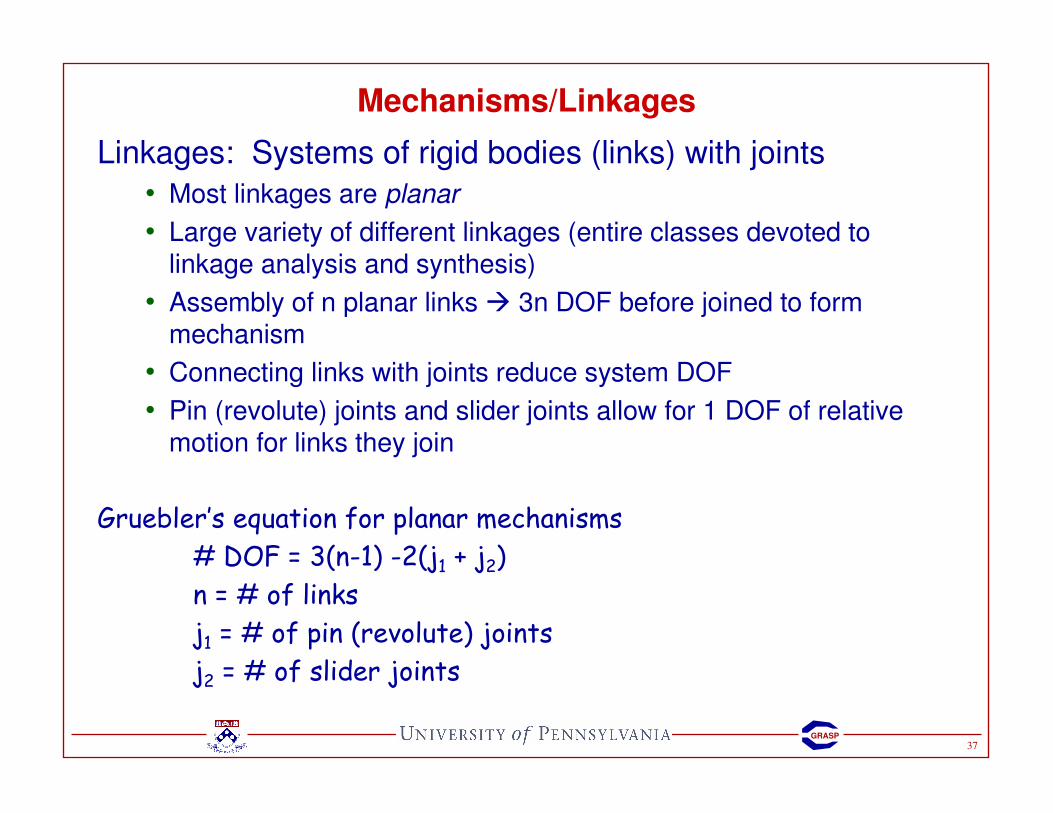
Linkages: Systems of rigid bodies (links) with joints
• Most linkages are planar
• Large variety of different linkages (entire classes devoted to linkage analysis and synthesis)
• Assembly of n planar links � 3n DOF before joined to form mechanism
• Connecting links with joints reduce system DOF
• Pin (revolute) joints and slider joints allow for 1 DOF of relative motion for links they join
Gruebler’s equation for planar mechanisms
# DOF = 3(n-1) -2(j1 + j2)
n = # of links
j1 = # of pin (revolute) joints
j2 = # of slider joints
Mechanisms/Linkages

38GRASP
Gruebler’s equation for planar mechanisms
# DOF = 3(n-1) -2(j1 + j2)
n = # of links
j1 = # of pin (revolute) joints
j2 = # of slider joints
Mechanisms/Linkages: Gruebler’s equation Ex.

39GRASP
Mechanisms/Linkages: Gruebler’s equation Ex.
Gruebler’s equation for planar mechanisms
# DOF = 3(n-1) -2(j1 + j2)
n = # of links
j1 = # of revolute joints
j2 = # of slider joints
40GRASP
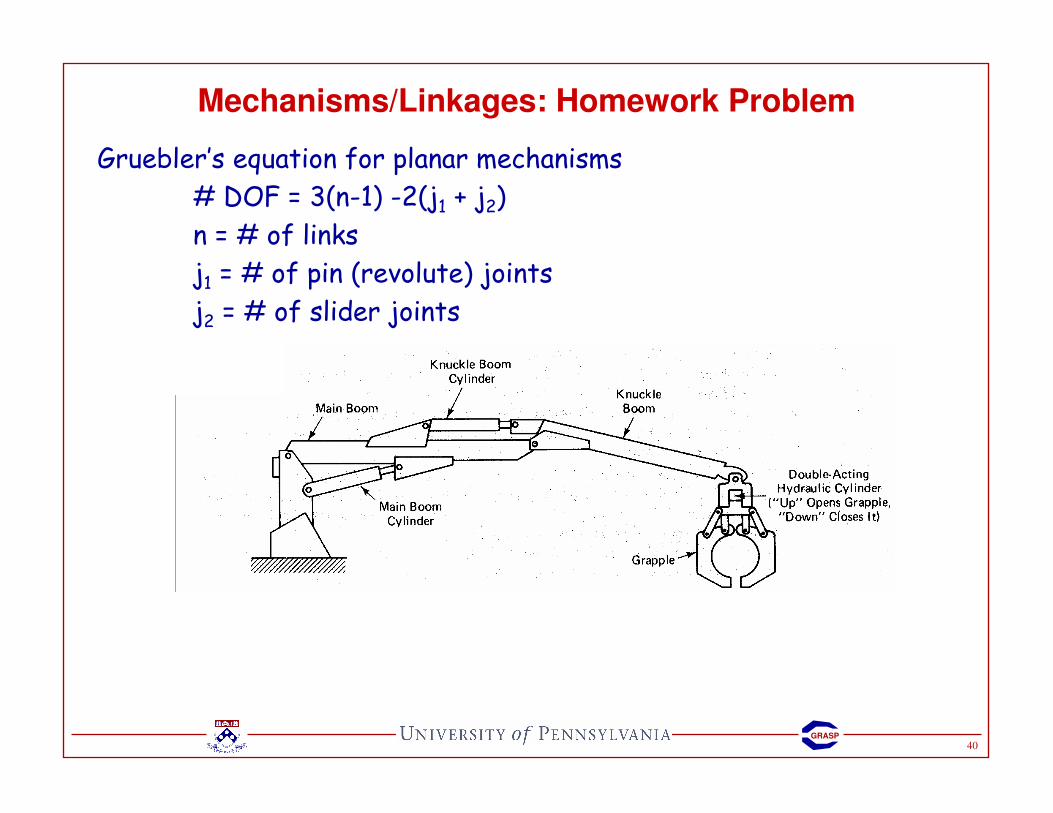
Mechanisms/Linkages: Homework Problem
Gruebler’s equation for planar mechanisms
# DOF = 3(n-1) -2(j1 + j2)
n = # of links
j1 = # of pin (revolute) joints
j2 = # of slider joints
41GRASP
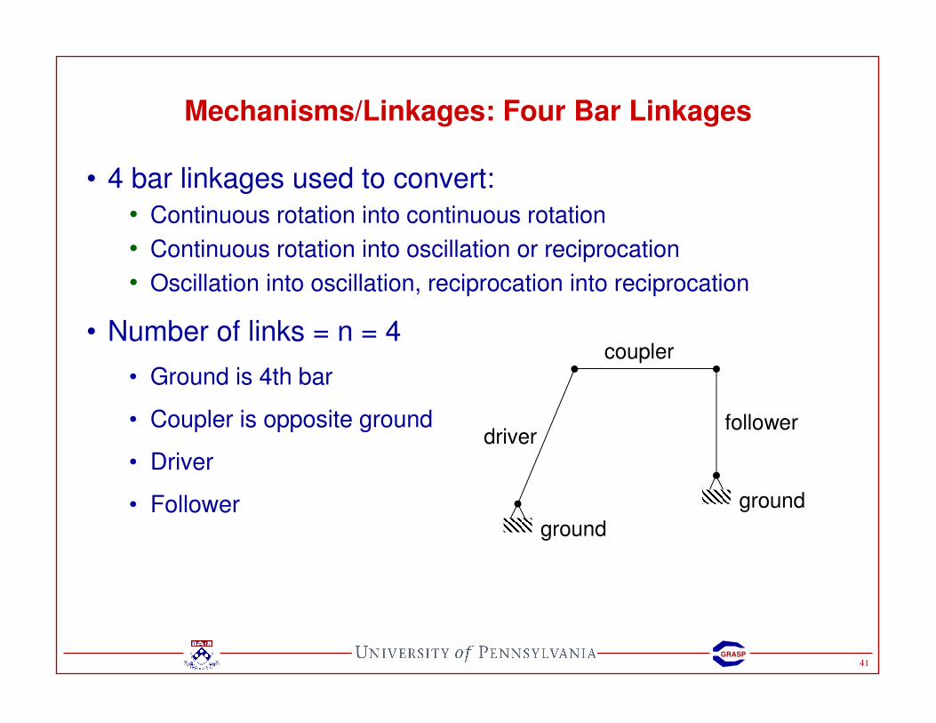
Mechanisms/Linkages: Four Bar Linkages
• 4 bar linkages used to convert:
• Continuous rotation into continuous rotation
• Continuous rotation into oscillation or reciprocation
• Oscillation into oscillation, reciprocation into reciprocation
• Number of links = n = 4
• Ground is 4th bar
• Coupler is opposite ground
• Driver
• Followerground
coupler
ground
driverfollower

42GRASP
Mechanisms/Linkages: Four Bar Linkages
s = shortest link; l = longest link; p, q = intermediate lengths
Grashof's theorem:
A four-bar mechanism has at least one revolving link if s + l <= p + q.
All three mobile links will rock if s + l > p + q.
All four-bar mechanisms fall into one of these four categories:
Case l + s vers. p + q Shortest Bar Type
1 < Frame Double-crank
2 < Side Crank-rocker
3 < Coupler Double-rocker
4 = Any Change Point
5 > Any Double-rocker
1) When the shortest link is a side link, the mechanism is a crank-rocker mechanism. The shortest link is the crank in the mechanism.
2) When the shortest link is the frame of the mechanism, the mechanism is a double-crank mechanism.
3) When the shortest link is the coupler link, the mechanism is a double-rocker mechanism.

43GRASP
Mechanisms/Linkages: Four Bar Linkages
When the shortest link is…
• a side link, the mechanism is
a crank-rocker mechanism.
• the frame of the mechanism,
the mechanism is a drag-link
mechanism.
• the coupler, the mechanism
is a double-rocker
mechanism.
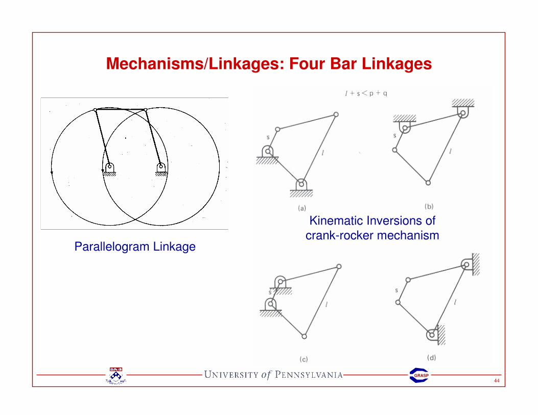
44GRASP
Mechanisms/Linkages: Four Bar Linkages
Kinematic Inversions of
crank-rocker mechanismParallelogram Linkage

45GRASP
Mechanisms/Linkages: Four Bar Linkages
Adjusting
Screw
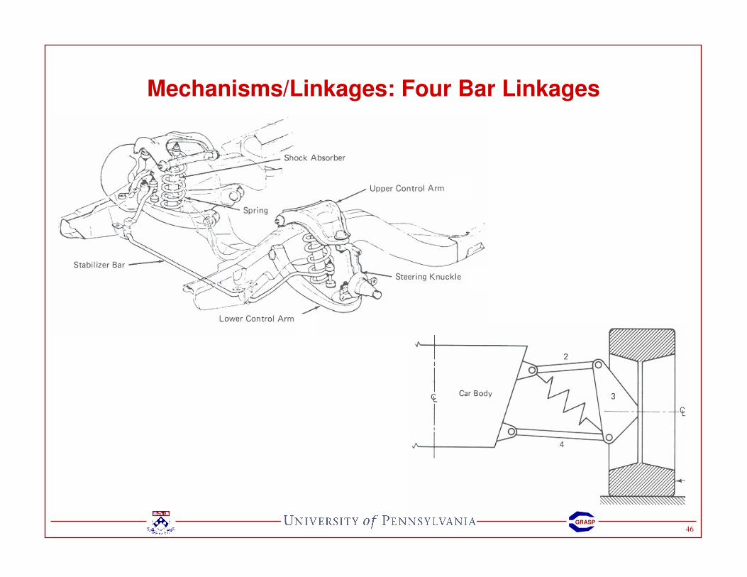
46GRASP
Mechanisms/Linkages: Four Bar Linkages

47GRASP
Mechanisms/Linkages: Examples
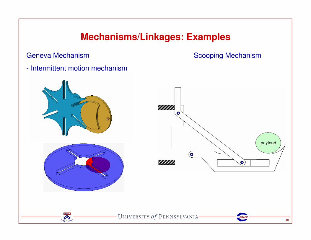
48GRASP
Mechanisms/Linkages: Examples
Geneva Mechanism
- Intermittent motion mechanism
Scooping Mechanism

49GRASP
Mechanisms/Linkages: Examples
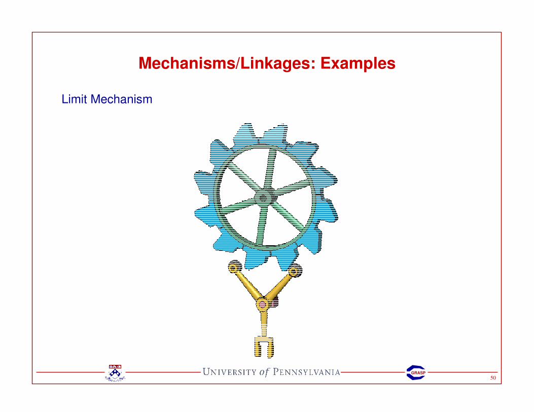
50GRASP
Mechanisms/Linkages: Examples
Limit Mechanism
51GRASP
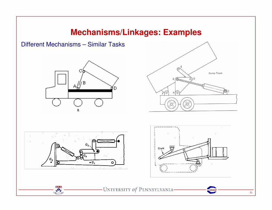
Mechanisms/Linkages: Examples
Different Mechanisms – Similar Tasks
Related Documents