QUICKLINK www.harmonicdrive.de/2020 Engineering Data CobaltLine®-2UH Units

Welcome message from author
This document is posted to help you gain knowledge. Please leave a comment to let me know what you think about it! Share it to your friends and learn new things together.
Transcript
QUICKLINKwww.harmonicdrive.de/2020
Engineering DataCobaltLine®-2UH Units
2 1019641 01/2016 V01
Contents
1. General ................................................................................................................................................. 031.1 Description of Safety Alert Symbols ...................................................................................................................................041.2 Disclaimer and Copyright .....................................................................................................................................................04
2. Safety and Installation Instructions ................................................................................................... 052.1 Hazards ................................................................................................................................................................................. 052.2 Intended Purpose .................................................................................................................................................................062.3 Non Intended Purpose ..........................................................................................................................................................062.4 Declaration of Conformity .................................................................................................................................................... 07
3. Technical Descriptions ......................................................................................................................... 083.1 Product Description ..............................................................................................................................................................08 3.2 Ordering Code .......................................................................................................................................................................093.3 Technical Data.... ....................................................................................................................................................................10 3.3.1 Generaly Technical Data .............................................................................................................................................10 3.3.2 Dimensions ..................................................................................................................................................................11 3.3.3 Minimum Housing Clearance..................................................................................................................................... 13 3.3.4 Accuracy ...................................................................................................................................................................... 13 3.3.5 Torsional Stiffness ..................................................................................................................................................... 13 3.3.6 Bearings ......................................................................................................................................................................14 3.3.7 Materials Used ........................................................................................................................................................... 15
4. Driving Arrangements .......................................................................................................................... 164.1 Selecting Harmonic Drive® Gears ..........................................................................................................................................18 4.1.1 Torque Based Dimensioning ...................................................................................................................................... 19 4.1.2 Life of the Wave Generator Bearing.......................................................................................................................... 21 4.1.3 Stiffness Based Dimensioning ................................................................................................................................. 224.2 Calculation of the Torsion Angle .......................................................................................................................................... 244.3 Accuracy of the Oldham Coupling ........................................................................................................................................ 244.4 Efficiency Versus Load ......................................................................................................................................................... 25 4.4.1 Efficiency Calculations .............................................................................................................................................. 25 4.4.2 Efficiency Tables........................................................................................................................................................ 264.5 No Load Starting-, Back Driving- and Running Torque ...................................................................................................... 28 4.5.1 No Load Running Torque .......................................................................................................................................... 28 4.5.2 No Load Starting Torque ........................................................................................................................................... 29 4.5.3 No Load Back Driving Torque .................................................................................................................................... 294.6 Life for Continuous Operation ............................................................................................................................................. 30 4.6.1 Output Bearing at Oscillating Motion ...................................................................................................................... 324.7 Permissible Static Tilting Moment ...................................................................................................................................... 334.8 Angle of Inclination .............................................................................................................................................................. 334.9 Lubrication ......................................................................................................................................................................... 34 4.9.1 Grease Lubrication .................................................................................................................................................... 34 4.9.2 Oil Lubrication ........................................................................................................................................................... 364.10 Axial Forces at the Wave Generator .....................................................................................................................................37
5. Installation and Operation .................................................................................................................. 385.1 Transport and Storage .......................................................................................................................................................... 385.2 Gear Condition at Delivery .................................................................................................................................................... 385.3 Assembly Information .......................................................................................................................................................... 38 5.4 Recommended Tolerances for Assembly ............................................................................................................................ 395.5 Lubrication ............................................................................................................................................................................ 39 5.5.1 Grease Lubrication .................................................................................................................................................... 39 5.5.2 Amount of Grease .....................................................................................................................................................40 5.5.3 Additional Grease Package ........................................................................................................................................41 5.5.4 Grease Change ........................................................................................................................................................... 42 5.5.5 Oil Lubrication ........................................................................................................................................................... 42
31019641 01/2016 V01
5.6 Preparation for Assembly .................................................................................................................................................... 435.7 Assembly ...............................................................................................................................................................................44 5.7.1 Motor Assembly ........................................................................................................................................................44 5.7.2 Wave Generator Components .................................................................................................................................. 46 5.7.3 Mounting the Wave Generator (WG) to the Motor Shaft .......................................................................................48 5.7.4 Check before assembly of the Wave Generator WG) ..............................................................................................48 5.7.5 Assembly Control ...................................................................................................................................................... 49 5.7.6 Assembly of the Output Flange ............................................................................................................................... 50 5.7.7 Assembly of the Housing ......................................................................................................................................... 50
6. Decommissioning and Disposal ........................................................................................................... 51
7. Glossary .................................................................................................................................................537.1 Technical Data ....................................................................................................................................................................... 537.2 Labelling, Guidelines and Regulations ................................................................................................................................ 59
1. General
About this documentationThis document contains safety instructions, technical data and operation rules for products of Harmonic Drive AG. The documentation is aimed at planners, project engineers, commissioning engineers and machine manufacturers, offering support during selection and calculation of the servo actuators, servo motors and accessories.
Rules for storagePlease keep this document for the entire life of the product, up to its disposal. Please hand over the documentation when re-selling the product.
Additional documentationFor the configuration of drive systems using the products of Harmonic Drive AG, you may require additional documents. Documentation is provided for all products offered by Harmonic Drive AG and can be found in pdf format on the website.
www.harmonicdrive.de
Third-party systemsDocumentation for parts supplied by third party suppliers, associated with Harmonic Drive® components, is not included in our standard documentation and should be requested directly from the manufacturers.
Before commissioning products from Harmonic Drive AG with servo drives, we advise you to obtain the relevant documents for each device.
Your feedbackYour experiences are important to us. Please send suggestions and comments about the products and documentation to:
Harmonic Drive AGMarketing and CommunicationsHoenbergstraße 1465555 Limburg / LahnGermanyE-Mail: [email protected]
4 1019641 01/2016 V01
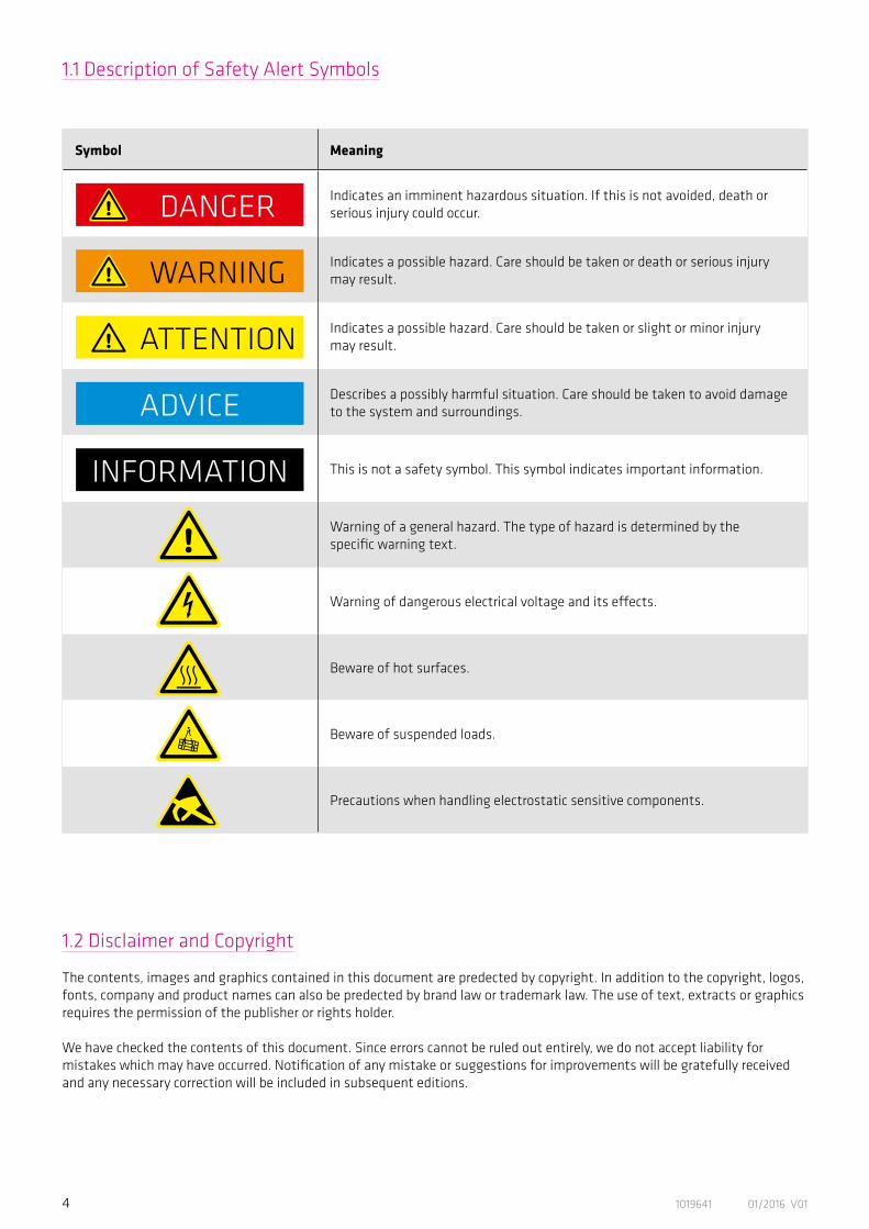
1.1 Description of Safety Alert Symbols
Symbol Meaning
Indicates an imminent hazardous situation. If this is not avoided, death or serious injury could occur.
Indicates a possible hazard. Care should be taken or death or serious injury may result.
Indicates a possible hazard. Care should be taken or slight or minor injury may result.
Describes a possibly harmful situation. Care should be taken to avoid damage to the system and surroundings.
This is not a safety symbol. This symbol indicates important information.
Warning of a general hazard. The type of hazard is determined by the specific warning text.
Warning of dangerous electrical voltage and its effects.
Beware of hot surfaces.
Beware of suspended loads.
Precautions when handling electrostatic sensitive components.
1.2 Disclaimer and Copyright
The contents, images and graphics contained in this document are predected by copyright. In addition to the copyright, logos, fonts, company and product names can also be predected by brand law or trademark law. The use of text, extracts or graphics requires the permission of the publisher or rights holder.
We have checked the contents of this document. Since errors cannot be ruled out entirely, we do not accept liability for mistakes which may have occurred. Notification of any mistake or suggestions for improvements will be gratefully received and any necessary correction will be included in subsequent editions.
DANGER
WARNING
ATTENTION
INFORMATION
ADVICE
51019641 01/2016 V01
2. Safety and Installation Instructions
Please take note of the information and instructions in this document. Specialy designed models may differ in technical detail. If in doubt, we strong recommend that you contact the manufacturer, giving the type designation and serial number for clarification.
2.1 Hazards
Electric products have dangerous live and redating parts. All work during connection, operation, repair and disposal must be carried out by qualified personnel as described in the standards EN50110-1 and IEC 60364! Before starting any work, and especially before opening covers, the actuator must be properly isolated. In addition to the main circuits, the user also has to pay attention to any auxilliary circuits.
Observing the five safety rules:• Disconnect mains• Prevent reconnection • Test for absence of harmful voltages• Ground and short circuit • Cover or close off nearby live parts
The measures taken above must only be withdrawn when the work has been completed and the device is fully assembled. Improper handling can cause damage to persons and property. The respective national, local and factory specific regulations must be adhered to.
Electric, magnetic and electromagnetic fields are dangerous, in particular for persons with pacemakers, implants or similiar. Vulnerable groups must not be in the immediate vicinity of the products themselves.
Built-in holding brakes alone are not functional safe. Particularly with unsupported vertical axes, the functional safety and security can only be achieved with additional, external mechanical brakes.
The successful and safe operation of gears, products requires proper transport, storage and assembly as well as correct operation and maintenance.
The surface temperature of gears, motors and actuators can exceed 55 degrees Celsius. The hot surfaces should not be touched.
DANGER
DANGER
DANGER
ATTENTION
WARNING

6 1019641 01/2016 V01
2.2 Intended Purpose
The Harmonic Drive® products are intended for industrial or commercial applications. They comply with the relevant parts of the harmonised EN 60034 standards series.
Typical areas of application are robotics and handling, machine tools, packaging and food machines and similar machines.
The products may only be operated within the operating ranges and environmental conditions shown in the documentation (altitude, degree of predection, temperature range etc).Before plant and machinery which have Harmonic Drive® products built into them are commissioned, the compliance must be established with the Machinery Directive, Low Voltage Directive and EMC guidelines.
Plant and machinery with inverter driven motors must satisfy the predection requirements in the EMC guidelines. It is the responsibility of the installer to ensure that installation is undertaken correctly.Signal and power lines must be shielded. The EMC instructions from the inverter manufacturer must be observed in order that installation meets the EMC regulations.
2.3 Non Intended Purpose
The use of products outside the areas of application mentioned above or, inter alia, other than in the operating areas or environmental conditions described in the documentation is considered as non-intended purpose.
The following areas of application are, inter alia, those considered as non-intended purpose:
• Aerospace • Areas at risk of explosion• Machines specially constructed or used for a nuclear purpose whose breakdown might lead to the emission of radio-activity• Vacuum• Machines for domestic use• Medical equipment which comes into direct contact with the human body• Machines or equipment for transporting or lifting people• Special devices for use in annual markets or leisure parks
Movement and lifting of products with a mass > 20 Kg should only be carried out with suitable lifting gear.
Cables must not come into direct contact with hot surfaces.
Special versions of drive systems and motors may have differing specifications. Please consider all data sheet, catalogues and offers etc. sent concerning these special versions.
ADVICE
ADVICE
ADVICE
INFORMATION

71019641 01/2016 V01
2.4 Declaration of Conformity
Harmonic Drive® gears are components for installation in machines as defined by the machine directive 89/392/EWG. Commissioning is prohibited until such time as the end product has been proved to conform to the provisions of this directive.
Essential health and safety requirements were considered in the design and manufacture of these gear component sets. This simplifies the implementation of the machinery directive by the end user for the machinery or the partly completed machinery. Commissioning of the machine or partly completed machine is prohibited until the final product conforms to the EC Machinery Directive.
8 1019641 01/2016 V01
CobaltLine®-2UH Series Units are available in six sizes with gear ratios of 50, 80, 100, 120 and 160:1 offering repeatable peak torques from 23 to 841 Nm.
The output bearing with high tilting capacity often allows direct attachment of heavy payloads without the need for further support, thereby providing simple and space saving design installations.
They cover a wide torque range and feature long service life. If required, the Units are available as specific configurations tailored to your application. Standard servo motors can be attached in a compact manner. The CobaltLine® Series can be usedfor ambient temperatures between -40 °C and 90 °C.
3. Technical Descriptions
3.1 Product Description
Maximum torque capacity withextended temperature range
91019641 01/2016 V01
Table 9.1
Table 9.2
- - - -
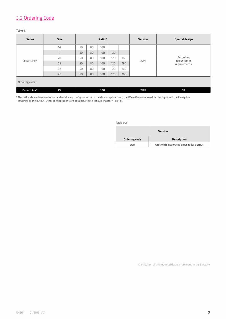
Version
Ordering code Description
2UH Unit with integrated cross roller output
3.2 Ordering Code
Clarification of the technical data can be found in the Glossary
Series Size Ratio1) Version Special design
CobaltLine®
14 50 80 100
2UHAccording
to customerrequirements
17 50 80 100 120
20 50 80 100 120 160
25 50 80 100 120 160
32 50 80 100 120 160
40 50 80 100 120 160
Ordering code
CobaltLine® 25 100 2UH SP
1) The ratios shown here are for a standard driving configuration with the circular spline fixed, the Wave Generator used for the input and the Flexspline attached to the output. Other configurations are possible. Please consult chapter 4 “Ratio”.

10 1019641 01/2016 V01
3.3 Technical Data
3.3.1 Generaly Technical Data
Table 10.1
Table 10.2
Unit CobaltLine®-14-2UH CobaltLine®-17-2UH
Ratio i [ ] 50 80 100 50 80 100 120
Repeatable peak toque TR [Nm] 23 30 36 44 56 70 70
Average torque TA [Nm] 9.0 14 14 34 35 51 51
Rated torque TN [Nm] 7.0 10 10 21 29 31 31
Momentary peak torque TM [Nm] 46 61 70 91 113 143 112
Maximum input speed (oil lubrication) nin (max) [rpm] 14000 10000
Maximum input speed (grease lubrication) nin (max) [rpm] 8500 7300
Average input speed (oil lubrication) nav (max) [rpm] 6500 6500
Average input speed (grease lubrication) nav (max) [rpm] 3500 3500
Moment of inertia Jin [x10-4 kgm²] 0.033 0.079
Weight m [kg] 0.52 0.68
Unit CobaltLine®-20-2UH CobaltLine®-25-2UH
Ratio i [ ] 50 80 100 120 160 50 80 100 120 160
Repeatable peak toque TR [Nm] 73 96 107 113 120 127 178 204 217 229
Average torque TA [Nm] 44 61 64 64 64 72 113 140 140 140
Rated torque TN [Nm] 33 44 52 52 52 51 82 87 87 87
Momentary peak torque TM [Nm] 127 165 191 191 191 242 332 369 395 408
Maximum input speed (oil lubrication) nin (max) [rpm] 10000 7500
Maximum input speed (grease lubrication) nin (max) [rpm] 6500 5600
Average input speed (oil lubrication) nav (max) [rpm] 6500 5600
Average input speed (grease lubrication) nav (max) [rpm] 3500 3500
Moment of inertia Jin [x10-4 kgm²] 0.193 0.413
Weight m [kg] 0.98 1.5
111019641 01/2016 V01
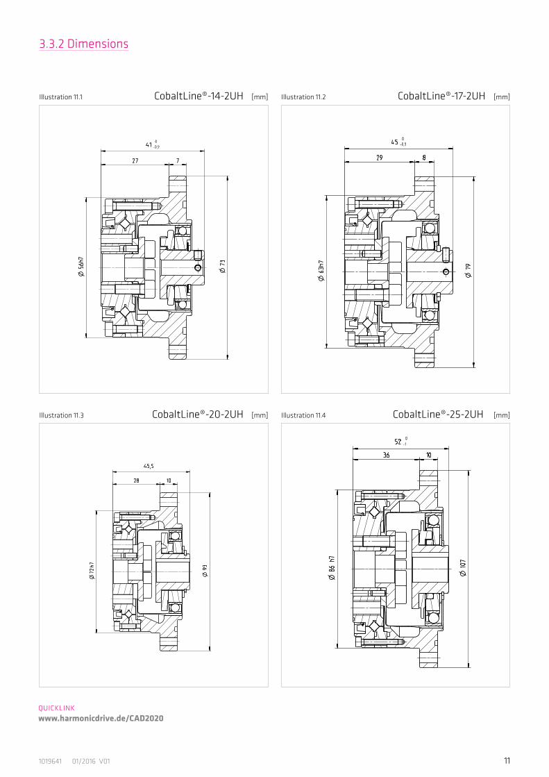
3.3.2 Dimensions
QUICKLINK www.harmonicdrive.de/CAD2020
Illustration 11.1 Illustration 11.2[mm] [mm]CobaltLine®-14-2UH CobaltLine®-17-2UH
CobaltLine®-20-2UH CobaltLine®-25-2UHIllustration 11.3 Illustration 11.4[mm] [mm]
12 1019641 01/2016 V01
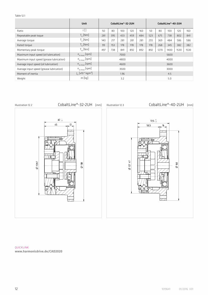
Table 12.1
Unit CobaltLine®-32-2UH CobaltLine®-40-2UH
Ratio i [ ] 50 80 100 120 160 50 80 100 120 160
Repeatable peak toque TR [Nm] 281 395 433 459 484 523 675 738 802 841
Average torque TA [Nm] 140 217 281 281 281 255 369 484 586 586
Rated torque TN [Nm] 99 153 178 178 178 178 268 345 382 382
Momentary peak torque TM [Nm] 497 738 841 892 892 892 1270 1400 1530 1530
Maximum input speed (oil lubrication) nin (max) [rpm] 7000 5600
Maximum input speed (grease lubrication) nin (max) [rpm] 4800 4000
Average input speed (oil lubrication) nav (max) [rpm] 4600 3600
Average input speed (grease lubrication) nav (max) [rpm] 3500 3000
Moment of inertia Jin [x10-4 kgm²] 1.96 4.5
Weight m [kg] 3.2 5.0
Illustration 12.2 Illustration 12.3[mm] [mm]CobaltLine®-32-2UH CobaltLine®-40-2UH
QUICKLINK www.harmonicdrive.de/CAD2020
131019641 01/2016 V01
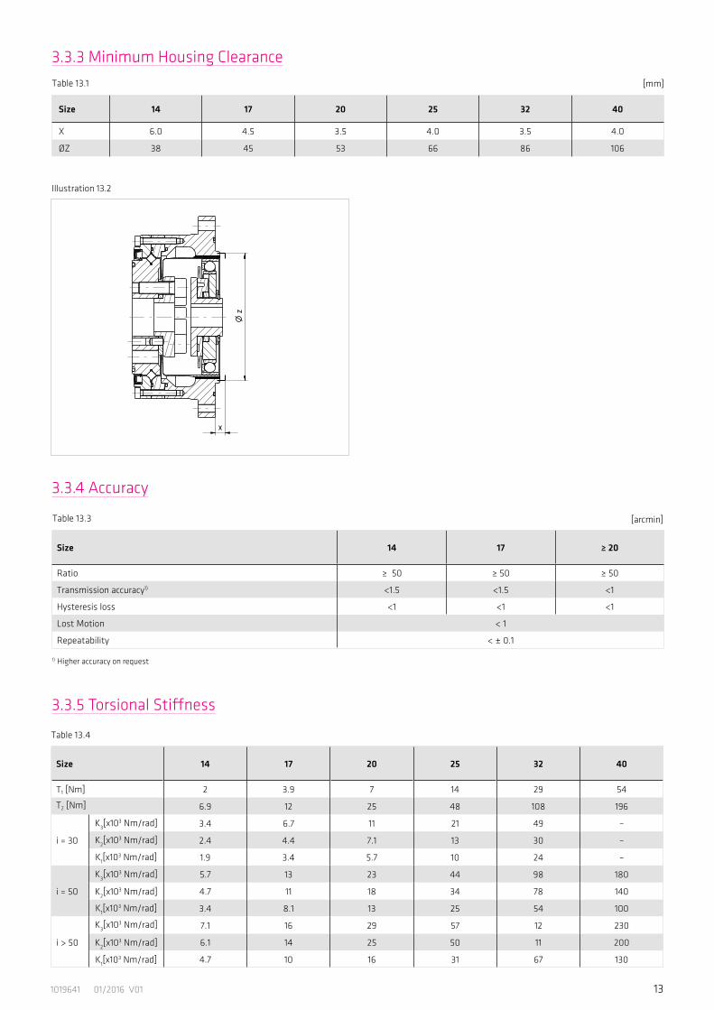
3.3.3 Minimum Housing Clearance
3.3.4 Accuracy
Size 14 17 ≥ 20
Ratio ≥ 50 ≥ 50 ≥ 50
Transmission accuracy1) <1.5 <1.5 <1
Hysteresis loss <1 <1 <1
Lost Motion < 1
Repeatability < ± 0.1
[arcmin]
1) Higher accuracy on request
Table 13.3
Table 13.4
3.3.5 Torsional Stiffness
Illustration 13.2
[mm]
Size 14 17 20 25 32 40
X 6.0 4.5 3.5 4.0 3.5 4.0
ØZ 38 45 53 66 86 106
Table 13.1
Size 14 17 20 25 32 40
T1 [Nm] 2 3.9 7 14 29 54
T2 [Nm] 6.9 12 25 48 108 196
i = 30
K3[x103 Nm/rad] 3.4 6.7 11 21 49 –
K2[x103 Nm/rad] 2.4 4.4 7.1 13 30 –
K1[x103 Nm/rad] 1.9 3.4 5.7 10 24 –
i = 50
K3[x103 Nm/rad] 5.7 13 23 44 98 180
K2[x103 Nm/rad] 4.7 11 18 34 78 140
K1[x103 Nm/rad] 3.4 8.1 13 25 54 100
i > 50
K3[x103 Nm/rad] 7.1 16 29 57 12 230
K2[x103 Nm/rad] 6.1 14 25 50 11 200
K1[x103 Nm/rad] 4.7 10 16 31 67 130
14 1019641 01/2016 V01
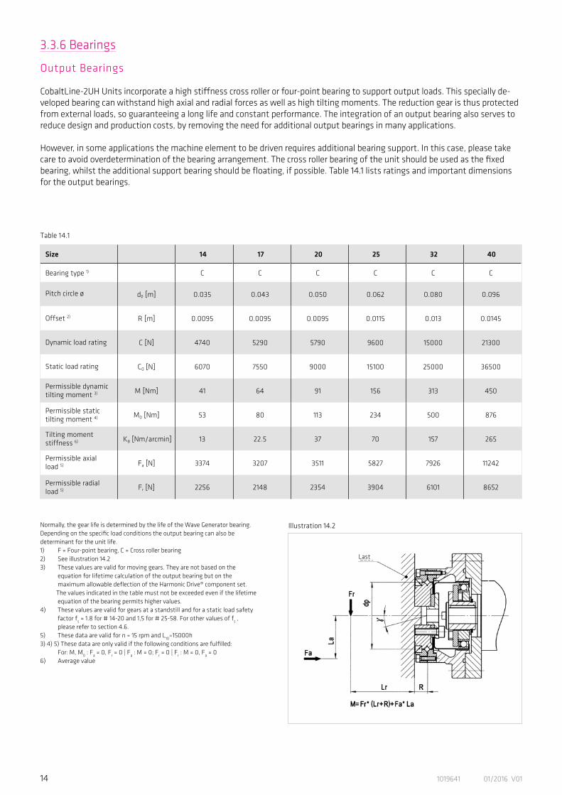
Table 14.1
3.3.6 Bearings
Output Bearings
CobaltLine-2UH Units incorporate a high stiffness cross roller or four-point bearing to support output loads. This specially de-veloped bearing can withstand high axial and radial forces as well as high tilting moments. The reduction gear is thus protected from external loads, so guaranteeing a long life and constant performance. The integration of an output bearing also serves to reduce design and production costs, by removing the need for additional output bearings in many applications.
However, in some applications the machine element to be driven requires additional bearing support. In this case, please take care to avoid overdetermination of the bearing arrangement. The cross roller bearing of the unit should be used as the fixed bearing, whilst the additional support bearing should be floating, if possible. Table 14.1 lists ratings and important dimensions for the output bearings.
Size 14 17 20 25 32 40
Bearing type 1) C C C C C C
Pitch circle ø dp [m] 0.035 0.043 0.050 0.062 0.080 0.096
Offset 2) R [m] 0.0095 0.0095 0.0095 0.0115 0.013 0.0145
Dynamic load rating C [N] 4740 5290 5790 9600 15000 21300
Static load rating C0 [N] 6070 7550 9000 15100 25000 36500
Permissible dynamictilting moment 3) M [Nm] 41 64 91 156 313 450
Permissible statictilting moment 4) M0 [Nm] 53 80 113 234 500 876
Tilting momentstiffness 6) KB [Nm/arcmin] 13 22.5 37 70 157 265
Permissible axialload 5) Fa [N] 3374 3207 3511 5827 7926 11242
Permissible radialload 5) Fr [N] 2256 2148 2354 3904 6101 8652
Illustration 14.2
Last
Normally, the gear life is determined by the life of the Wave Generator bearing.Depending on the specific load conditions the output bearing can also bedeterminant for the unit life.1) F = Four-point bearing, C = Cross roller bearing2) See illustration 14.23) These values are valid for moving gears. They are not based on the equation for lifetime calculation of the output bearing but on the maximum allowable deflection of the Harmonic Drive® component set.
The values indicated in the table must not be exceeded even if the lifetime equation of the bearing permits higher values.4) These values are valid for gears at a standstill and for a static load safety factor fs = 1.8 for # 14-20 and 1,5 for # 25-58. For other values of fs , please refer to section 4.6.5) These data are valid for n = 15 rpm and L10=15000h3) 4) 5) These data are only valid if the following conditions are fulfilled: For: M, M0 : Fa = 0, Fr = 0 | Fa : M = 0; Fr = 0 | Fr : M = 0, Fa = 06) Average value
151019641 01/2016 V01
3.3.7 Materials Used
Materials:Housing: Cast iron and bearing steel.Adapter flange, if supplied by Harmonic Drive AG: high tensile aluminium or steel.
Surfaces:Screws: Black phosphatized.Housing: Bright.Output bearing: Bright bearing steel.
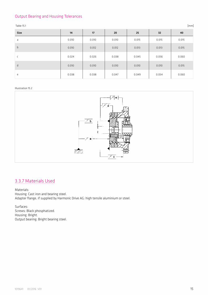
Illustration 15.2
Table 15.1 [mm]
Size 14 17 20 25 32 40
a 0.010 0.010 0.010 0.015 0.015 0.015
b 0.010 0.012 0.012 0.013 0.013 0.015
c 0.024 0.026 0.038 0.045 0.056 0.060
d 0.010 0.010 0.010 0.010 0.010 0.015
e 0.038 0.038 0.047 0.049 0.054 0.060
Output Bearing and Housing Tolerances
16 1019641 01/2016 V01
4. Driving Arrangements
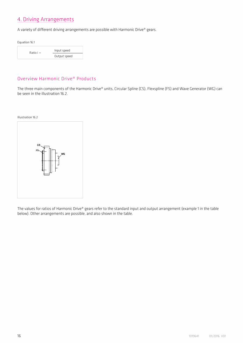
A variety of different driving arrangements are possible with Harmonic Drive® gears.
Overview Harmonic Drive® Products
The three main components of the Harmonic Drive® units, Circular Spline (CS), Flexspline (FS) and Wave Generator (WG) can be seen in the illustration 16.2.
Ratio i = Input speed
Output speed
Equation 16.1
Illustration 16.2
The values for ratios of Harmonic Drive® gears refer to the standard input and output arrangement (example 1 in the table below). Other arrangements are possible, and also shown in the table.
171019641 01/2016 V01
FS WGCS
Ratio = -
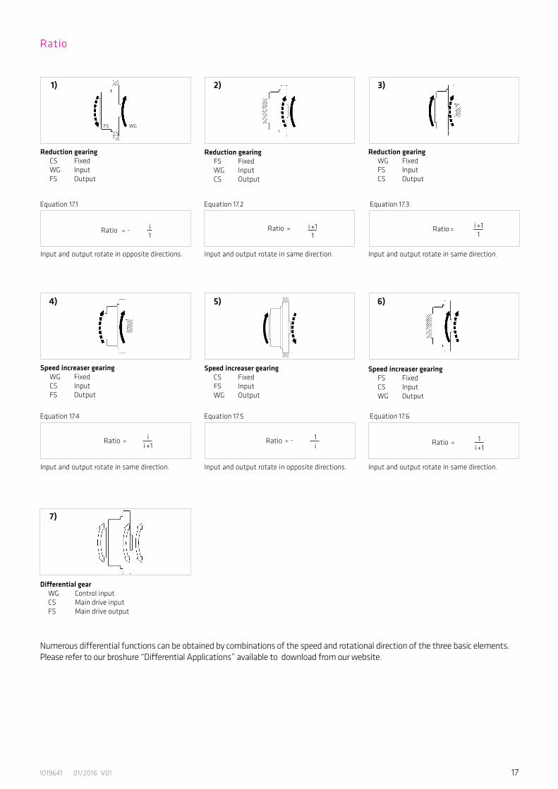
Reduction gearing CS Fixed WG Input FS Output
Reduction gearing FS Fixed WG Input CS Output
Reduction gearing WG Fixed FS Input CS Output
Differential gear WG Control input CS Main drive input FS Main drive output
Numerous differential functions can be obtained by combinations of the speed and rotational direction of the three basic elements. Please refer to our broshure “Differential Applications” available to download from our website.
Input and output rotate in opposite directions. Input and output rotate in same direction. Input and output rotate in same direction.
Equation 17.1
Equation 17.4
1) 2) 3)
Equation 17.2
Equation 17.5
Equation 17.3
Equation 17.6
Speed increaser gearing WG Fixed
CS Input FS Output
Speed increaser gearing CS Fixed FS Input WG Output
Speed increaser gearing FS Fixed CS Input WG Output
Input and output rotate in same direction. Input and output rotate in opposite directions. Input and output rotate in same direction.
4) 5) 6)
7)
Ratio
i1
Ratio = i +11
Ratio = i +11
Ratio = ii +1
Ratio = - 1i Ratio = 1
i +1
18 1019641 01/2016 V01
4.1 Selecting Harmonic Drive® Gears
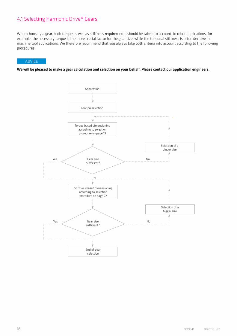
When choosing a gear, both torque as well as stiffness requirements should be take into account. In robot applications, for example, the necessary torque is the more crucial factor for the gear size, while the torsional stiffness is often decisive in machine tool applications. We therefore recommend that you always take both criteria into account according to the following procedures.
Gear preselection
Application
Gear sizesufficient?
Gear sizesufficient?
Selection of abigger size
Yes
Yes
No
No
Selection of abigger size
End of gearselection
Torque based dimensioningaccording to selectionprocedure on page 19
Stiffness based dimensioning according to selectionprocedure on page 22
ADVICE
We will be pleased to make a gear calculation and selection on your behalf. Please contact our application engineers.
191019641 01/2016 V01
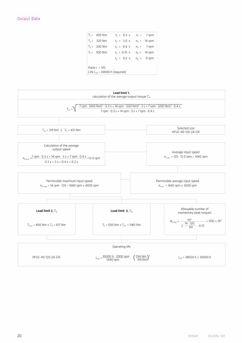
4.1.1 Torque Based Dimensioning
Output Data
Zeit
n1
n2
t2
T2
t3
np
tp t1
T1
n1n3
t1
T1
Torq
ueSp
eed
T3
Zeit
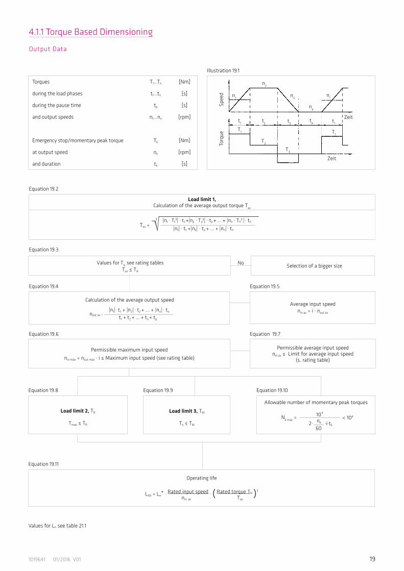
Torques T1...Tn [Nm]
during the load phases t1...tn [s]
during the pause time tp [s]
and output speeds n1...nn [rpm]
Emergency stop/momentary peak torque Tk [Nm]
at output speed nk [rpm]
and duration tk [s]
Equation 19.2
Illustration 19.1
Permissible maximum input speed
nin max = nout max · i ≤ Maximum input speed (see rating table)
Load limit 2, TR
Tmax ≤ TR
Operating life
L50 = Ln* · Rated input speed · ( Rated torque TN )3
nin av Tav
nout av =
|n1|· t1 + |n2| · t2 + ... + |nn| · tn
t1 + t2 + ... + tn + tp
Equation 19.4
Equation 19.6
Equation 19.8
Equation 19.11
Equation 19.9 Equation 19.10
Equation 19.5
Equation 19.7
Selection of a bigger sizeNo
Equation 19.3
Load limit 3, TM
Tk ≤ TM
Allowable number of momentary peak torques
Nk max = 104
2· nk ·i·tk 60
Permissible average input speednin av ≤ Limit for average input speed
(s. rating table)
Values for TA see rating tablesTav ≤ TA
Calculation of the average output speed
Load limit 1, Calculation of the average output torque Tav
3 |n1 · T13| · t1 +|n2 · T2
3| · t2 + ... + |nn · Tn3 | · tn
|n1| · t1 +|n2| · t2 + ... + |nn| · tnTav =
Average input speednin av = i · nout av
< 104
Values for Ln see table 21.1
20 1019641 01/2016 V01
Output Data
T1 = 400 Nm t1 = 0.3 s n1 = 7 rpm
T2 = 320 Nm t2 = 3.0 s n2 = 14 rpm
T3 = 200 Nm t3 = 0.4 s n3 = 7 rpm
Tk = 500 Nm tk = 0.15 s nk = 14 rpm
tp = 0.2 s np = 0 rpm
Ratio i = 120Life L50 = 30000 h (required)
Load limit 1,calculation of the average output torque Tav
Tav = 319 Nm ≤ TA = 451 Nm Selected sizeHFUC-40-120-2A-GR
Calculation of the averageoutput speed
Average input speednin av = 120 · 12.0 rpm = 1440 rpmnout av =
7 rpm · 0.3 s + 14 rpm · 3 s + 7 rpm · 0.4 s =12.0 rpm0.3 s + 3 s + 0.4 s + 0.2 s
Permissible maximum input speednin max = 14 rpm · 120 = 1680 rpm ≤ 4000 rpm
Permissible average input speednin av = 1440 rpm ≤ 3000 rpm
Load limit 2, TR Load limit 3, TMAllowable number of
momentary peak torques
Tmax = 400 Nm ≤ TR = 617 Nm Tk = 500 Nm ≤ TM = 1180 Nm
104
14 · 120
2 · 60 · 0.15
Operating life
HFUC-40-120-2A-GR: L50 = 35000 h · 2000 rpm · ( 294 Nm )3
1440 rpm 319 NmL50 = 38054 h > 30000 h
3 7 rpm · (400 Nm)3 · 0.3 s + 14 rpm · (320 Nm)3 · 3 s + 7 rpm · (200 Nm) 3 · 0.4 s
7 rpm · 0.3 s + 14 rpm · 3 s + 7 rpm · 0.4 sTav =
Nk max = = 1190 < 104
211019641 01/2016 V01
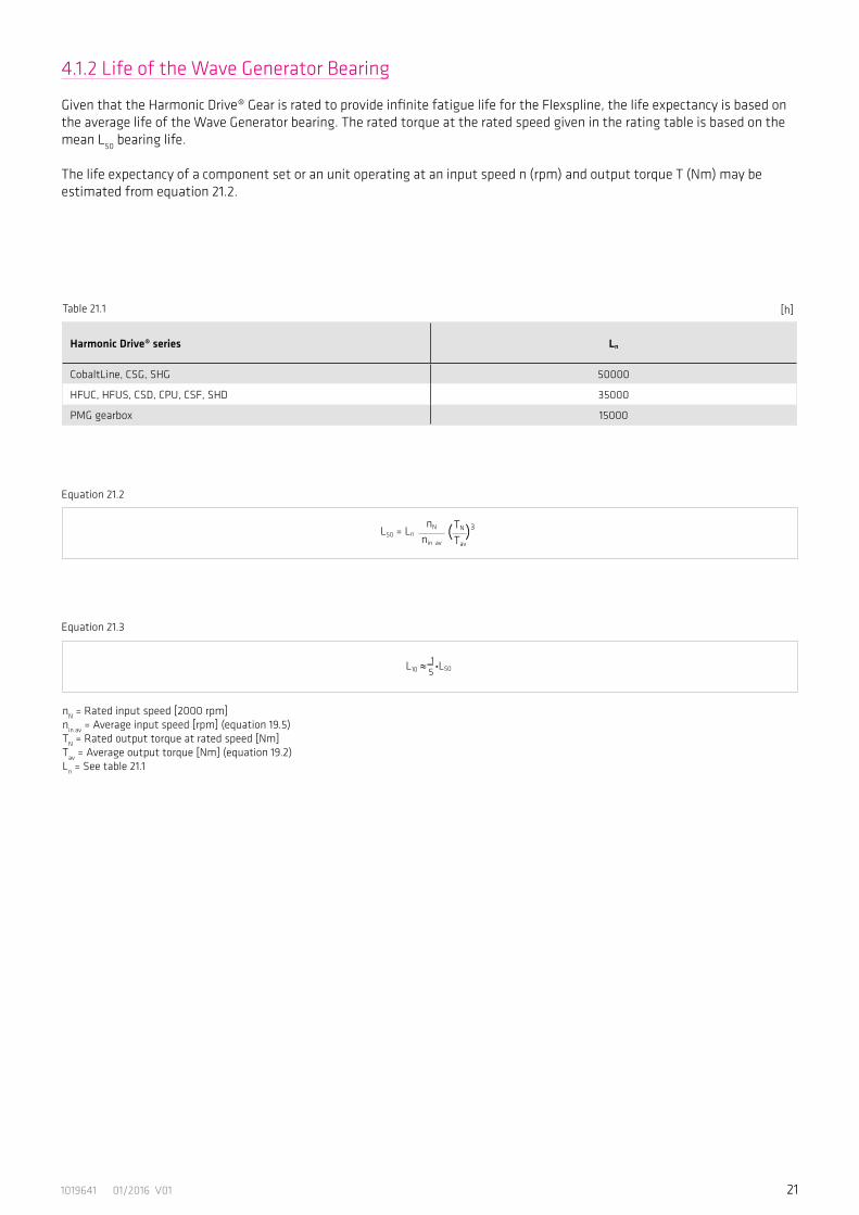
Harmonic Drive® series Ln
CobaltLine, CSG, SHG 50000
HFUC, HFUS, CSD, CPU, CSF, SHD 35000
PMG gearbox 15000
[h]
L50 = LnnN
nin av
TN
Tav( )3
L10 ≈ 1–5 •L50
nN = Rated input speed [2000 rpm]nin av = Average input speed [rpm] (equation 19.5)TN = Rated output torque at rated speed [Nm]Tav = Average output torque [Nm] (equation 19.2)Ln = See table 21.1
4.1.2 Life of the Wave Generator Bearing
Given that the Harmonic Drive® Gear is rated to provide infinite fatigue life for the Flexspline, the life expectancy is based on the average life of the Wave Generator bearing. The rated torque at the rated speed given in the rating table is based on the mean L50 bearing life.
The life expectancy of a component set or an unit operating at an input speed n (rpm) and output torque T (Nm) may be estimated from equation 21.2.
Table 21.1
Equation 21.2
Equation 21.3

22 1019641 01/2016 V01
* Depending on the application, a secondary gear stage may be useful. Please contact Harmonic Drive AG for more information..
Application fn
Slowly rotating turntables, base axes of slow moving welding robots (not laser welding), slowly rotating welding and swinging tables, gantry robot axes ≥ 4
Base axes of revolute robots, hand axes of revolute robots with low requirements regarding dynamic perfomance, tool revolvers, tool magazines, swivelling and positioning axes in medical and measuring devices ≥ 8
Standard applications in general mechanical engineering, tilting axes, palette changers, highly dynamic tool changers, revolvers and magazines, hand axes of robots, scara robots, gantry robots, polishing robots, dynamic welding manipuators, base axes of welding robots (laser welding), swivelling and positioning axes of medical equipment
≥ 15
B/C axes in 5 axis grinding machines, hand axes of welding robots (laser welding), milling heads for plastics machining ≥ 20
C axes in turning machines, milling heads for light metal machining,milling heads for woodworking (chipboards etc.) ≥ 25
Milling heads for woodworking (hardwood etc.) ≥ 30
C axes in turning machines* ≥ 35
Milling heads for metal machining*, B axes in turning milling centers for metal machining ≥ 40
Milling heads for metal machining*, B axes in turning milling centers for metal machining with high requirements regarding surface quality* ≥ 50
Milling heads for metal machining with very high requirements regarding surface quality* ≥ 60
In addition to the “Torque Based Dimensioning” stated on page 19, we recommend that you carry out a selection based on stiffness. For this, the values provided in table 22.1 for the individual resonance frequencies recommended for each application should be taken into account.
4.1.3 Stiffness Based Dimensioning
Table 22.1 [Hz]

231019641 01/2016 V01
Selection Example: Stiffness Based Dimensioning
Resonance Frequency (Gear Output)
The formula
fn = Resonance frequency [Hz]K1 = Gear torsional stiffness K1 [Nm/rad]J = Load moment of inertia [kgm2]
allows the calculation of the resonance frequency at the gear output from the given torsional stiffness, K1, of the Harmonic Drive® gear and the load‘s moment of inertia. The calculated frequency should correspond with the value provided in table 22.1. The higher the load‘s moment of inertia, the more influence the application has on the gear selection. If the moment of inertia = 0, the selected application has no numerical influence on the selection result.
Resonance Speed (Gear Input)
The resonance speed nn on the input side (motor side) can be calculated using the formula
nn = fn*30 [rpm]
During operation, we recommend that you pass the resonance speed rapidly. This can be achieved by selecting a suitable gearratio. Another possibility is to select suitable gear stiffness such that the resonance speed lies beyond the required speed range.
Selection Example
HFUC-40-120-2A-GR preselected from “Selection Procedure” on page 20.
Intended application: milling head for woodworkingMoment of inertia at the gear output: 7 kgm2. Recommended resonance frequency from table 22.1: ≥ 30 Hz.Resonance frequency using the preselected gearHFUC-40-120-2A-GR:
According to stiffness based dimensioning, this gear size is too small for the application.The larger gear HFUC-50-120-2A-GR results in a resonance frequency of:
Based on stiffness based dimensioning, the gear HFUC-50-120-2A-GR is recommended.
The resonance speed at the input (motor) amounts to:nn = 30*30 = 900 [rpm]
Either, this speed should be passed without stopping when accelerating / braking, or it should lie beyond the utilised speed range.
fn = . = 22 [Hz]1.3 . 105
71
2�
fn = . = 30 [Hz]2.5 . 105
71
2�
Equation 23.1
12�
K1
Jfn = [Hz]
24 1019641 01/2016 V01
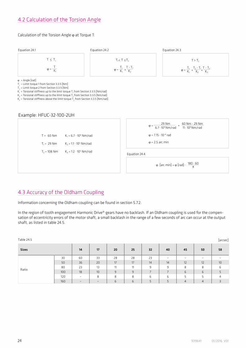
4.2 Calculation of the Torsion Angle
Calculation of the Torsion Angle φ at Torque T:
4.3 Accuracy of the Oldham Coupling
Information concerning the Oldham coupling can be found in section 5.7.2.
In the region of tooth engagement Harmonic Drive® gears have no backlash. If an Oldham coupling is used for the compen-sation of eccentricity errors of the motor shaft, a small backlash in the range of a few seconds of arc can occur at the output shaft, as listed in table 24.5.
φ = Angle [rad] T1 = Limit torque 1 from Section 3.3.5 [Nm]T2 = Limit torque 2 from Section 3.3.5 [Nm]K1 = Torsional stiffness up to the limit torque T1 from Section 3.3.5 [Nm/rad]K2 = Torsional stiffness up to the limit torque T2 from Section 3.3.5 [Nm/rad]K3 = Torsional stiffness above the limit torque T2 from Section 3.3.5 [Nm/rad]
φ = 60 Nm - 29 Nm11 . 104 Nm/rad
29 Nm6.7 . 104 Nm/rad
+
φ = 7.15 . 10-4 rad
φ = 2.5 arc min
180 . 60�φ [arc min] = φ [rad] .
Example: HFUC-32-100-2UH
T = 60 Nm K1 = 6.7 . 104 Nm/rad
T1 = 29 Nm K2 = 1.1 . 105 Nm/rad
T2 = 108 Nm K3 = 1.2 . 105 Nm/rad
T T1
T K1
<–
φ =
<
φ =T - T1
K2
T1
K1+
T1 T ≤T2
<T T2
φ =T2 - T1
K2
T1
K1
T - T2
K3+ +
Equation 24.1 Equation 24.2 Equation 24.3
Equation 24.4
Sizes 14 17 20 25 32 40 45 50 58
Ratio
30 60 33 28 28 23 – – – –50 36 20 17 17 14 14 12 12 1080 23 13 11 11 9 9 8 8 6100 18 10 9 9 7 7 6 6 5120 – 8 8 8 6 6 5 5 4160 – – 6 6 5 5 4 4 3
[arcsec]Table 24.5
251019641 01/2016 V01
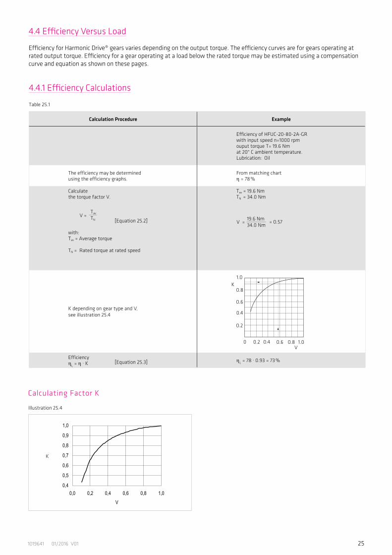
4.4.1 Efficiency Calculations
4.4 Efficiency Versus Load
Efficiency for Harmonic Drive® gears varies depending on the output torque. The efficiency curves are for gears operating atrated output torque. Efficiency for a gear operating at a load below the rated torque may be estimated using a compensationcurve and equation as shown on these pages.
Calculation Procedure Example
Efficiency of HFUC-20-80-2A-GR with input speed n=1000 rpm ouput torque T= 19.6 Nmat 20° C ambient temperature.Lubrication: Oil
The efficiency may be determinedusing the efficiency graphs.
From matching chart η = 78 %
Calculate the torque factor V.
with: Tav = Average torque TN = Rated torque at rated speed
Tav = 19.6 NmTN = 34.0 Nm
K depending on gear type and V,see illustration 25.4
EfficiencyηL = η . K ηL = 78 . 0.93 = 73 %
[Equation 25.2]
[Equation 25.3]
Calculating Factor K
V =Tav
TN
K
Table 25.1
1.0
0.8
0.6
0.2
0 0.2 0.4 0.6 0.8V
K
0.4
1.0
V = = 0.5719.6 Nm 34.0 Nm
Illustration 25.4

26 1019641 01/2016 V01
Efficiency for grease lubrication at rated torque Harmonic Drive® grease
Size 14
Illustration 26.1
Temperature [°C]
Ratio= 30100
90
80
70
60
50
40
30
20
Effic
ienc
y [%
]
Temperature [°C]
Ratio= 100100
90
80
70
60
50
40
30
20
Effic
ienc
y [%
]
20
30
40
50
60
70
80
90
100
-10 0 10 20 30 40
Umgebungstemp. / Ambient Temp.[°C]Wir
kungsg
rad / E
fficien
cy [%]
500 rpm
1000 rpm
2000 rpm
3500 rpm
Untersetzung / Ratio = 50,80
20
30
40
50
60
70
80
90
100
-10 0 10 20 30 40
Umgebungstemp. / Ambient Temp.[°C]
Wirkun
gsgrad
/ Effic
iency
[%]
500 rpm
1000 rpm
2000 rpm
3500 rpm
Untersetzung / Ratio = 30
Temperature [°C]
-10 0 10 20 30 40-10 0 10 20 30 40
20
30
40
50
60
70
80
90
100
-10 0 10 20 30 40
Umgebungstemp. / Ambient Temp.[°C]
Wirkun
gsgrad
/ Effic
iency
[%]
500 rpm
1000 rpm
2000 rpm
3500 rpm
Untersetzung / Ratio = 100
-10 0 10 20 30 40
Ratio= 50, 80100
90
80
70
60
50
40
30
20
Effic
ienc
y
500 rpm 500 rpm
1000 rpm 1000 rpm
2000 rpm 2000 rpm
3500 rpm 3500 rpm
500 rpm
1000 rpm
2000 rpm
3500 rpm
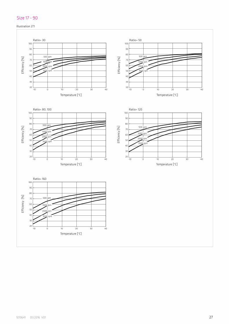
4.4.2 Efficiency Tables
271019641 01/2016 V01
Size 17 - 90
Illustration 27.1
Temperature [°C]
Ratio= 30100
90
80
70
60
50
40
30
20
Effic
ienc
y [%
]
Temperature [°C]
Ratio= 120100
90
80
70
60
50
40
30
20
Effic
ienc
y [%
]
20
30
40
50
60
70
80
90
100
-10 0 10 20 30 40
Umgebungstemp. / Ambient Temp.[°C]
Wirkun
gsgrad
/ Effic
iency
[%]
500 rpm
1000 rpm
2000 rpm
3500 rpm
Untersetzung / Ratio = 50
20
30
40
50
60
70
80
90
100
-10 0 10 20 30 40
Umgebungstemp. / Ambient Temp.[°C]
Wirkun
gsgrad
/ Effic
iency
[%]
500 rpm
1000 rpm
2000 rpm
3500 rpm
Untersetzung / Ratio = 30
Temperature [°C]
-10 0 10 20 30 40-10 0 10 20 30 40
20
30
40
50
60
70
80
90
100
-10 0 10 20 30 40
Umgebungstemp. / Ambient Temp.[°C]
Wirkun
gsgrad
/ Effic
iency
[%]
500 rpm
1000 rpm
2000 rpm
3500 rpm
Untersetzung / Ratio = 120
Temperature [°C]
Ratio= 80, 100100
90
80
70
60
50
40
30
20
Effic
ienc
y [%
]
20
30
40
50
60
70
80
90
100
-10 0 10 20 30 40
Umgebungstemp. / Ambient Temp.[°C]
Wirkun
gsgrad
/ Effic
iency
[%]
500 rpm
1000 rpm
2000 rpm
3500 rpm
Untersetzung / Ratio = 80,100
-10 0 10 20 30 40
Temperature [°C]
Ratio= 160100
90
80
70
60
50
40
30
20
Effic
ienc
y [%
]
20
30
40
50
60
70
80
90
100
-10 0 10 20 30 40
Umgebungstemp. / Ambient Temp.[°C]
Wirkun
gsgrad
/ Effic
iency
[%]
500 rpm
1000 rpm
2000 rpm
3500 rpm
Untersetzung / Ratio = 160
-10 0 10 20 30 40
-10 0 10 20 30 40
Ratio= 50100
90
80
70
60
50
40
30
20
Effic
ienc
y [%
] 500 rpm
1000 rpm
2000 rpm
3500 rpm
500 rpm
1000 rpm
2000 rpm
3500 rpm
500 rpm
1000 rpm
2000 rpm
3500 rpm
500 rpm
1000 rpm
2000 rpm
3500 rpm
500 rpm
1000 rpm
2000 rpm
3500 rpm

28 1019641 01/2016 V01
Illustration 28.1
No
load
runn
ing
torq
ue [N
cm]
No
load
runn
ing
torq
ue [N
cm]
No
load
runn
ing
torq
ue [N
cm]
10000
1000
100
10
1
0,1
10000
1000
100
10
1
0,1
10000
1000
100
10
1
0,1
Input Speed = 500 rpm
Input Speed = 2000 rpm Input Speed = 3500 rpm
Temperature [°C]
Temperature [°C] Temperature [°C]
-10 0 10 20 30 40
-10 0 10 20 30 40 -10 0 10 20 30 40
Size
Size Size
403225201714
403225201714
403225201714
403225201714
No
load
runn
ing
torq
ue [N
cm]
10000
1000
100
10
1
0,1
Input Speed = 1000 rpm
Temperature [°C]
-10 0 10 20 30 40
Size
4.5.1 No Load Running Torque
4.5 No Load Starting-, Back Driving- and Running Torque
No Load Running TorqueThe no load running torque is the torque required to maintain rotation of the input element (high speed side) at a defined inputspeed with no load applied to the output.
No Load Starting TorqueThe no load starting torque is the quasistatic torque required to commence rotation of the input element (high speed side) with no load applied to the output element (low speed side).
No Load Back Driving TorqueThe no load back driving torque is the torque required to commence rotation of the output element (low speed side) withno load applied to the input element (high speed side). The approximate range for no load back driving torque, based ontests of actual production gears, is shown in the matching table. In no case should the values given be regarded as a margin in a system that must hold an external load. Where back driving is not permissible a brake must be fitted.
The following curves are valid for: Harmonic Drive® grease, standard lubricant quantityGear ratio i = 100For other ratios please apply the compensation values below.For oil lubrication please contact Harmonic Drive AG.
291019641 01/2016 V01
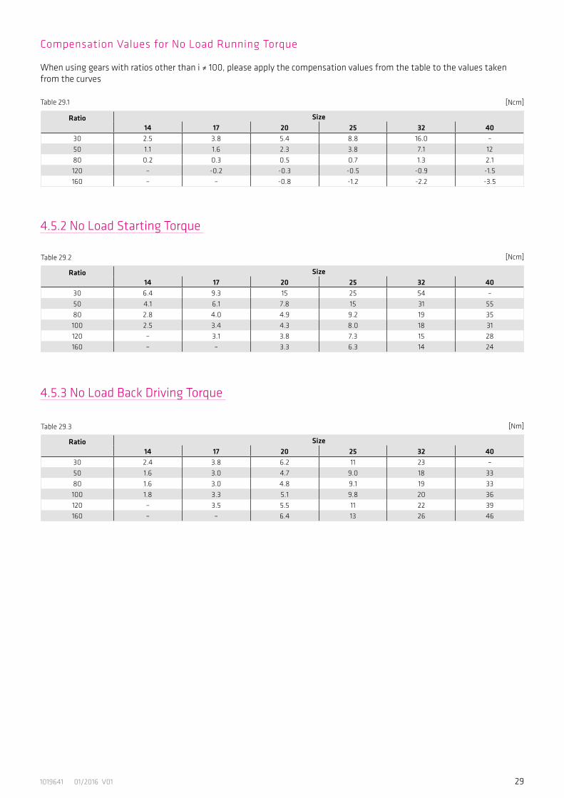
Table 29.1 [Ncm]
Table 29.3 [Nm]
Ratio Size 14 17 20 25 32 40
30 2.4 3.8 6.2 11 23 –50 1.6 3.0 4.7 9.0 18 3380 1.6 3.0 4.8 9.1 19 33100 1.8 3.3 5.1 9.8 20 36120 – 3.5 5.5 11 22 39160 – – 6.4 13 26 46
Table 29.2 [Ncm]
Ratio Size14 17 20 25 32 40
30 6.4 9.3 15 25 54 –50 4.1 6.1 7.8 15 31 5580 2.8 4.0 4.9 9.2 19 35100 2.5 3.4 4.3 8.0 18 31120 – 3.1 3.8 7.3 15 28160 – – 3.3 6.3 14 24
4.5.2 No Load Starting Torque
4.5.3 No Load Back Driving Torque
Ratio Size14 17 20 25 32 40
30 2.5 3.8 5.4 8.8 16.0 –50 1.1 1.6 2.3 3.8 7.1 1280 0.2 0.3 0.5 0.7 1.3 2.1120 – -0.2 -0.3 -0.5 -0.9 -1.5160 – – -0.8 -1.2 -2.2 -3.5
Compensation Values for No Load Running Torque
When using gears with ratios other than i ≠ 100, please apply the compensation values from the table to the values taken from the curves
30 1019641 01/2016 V01
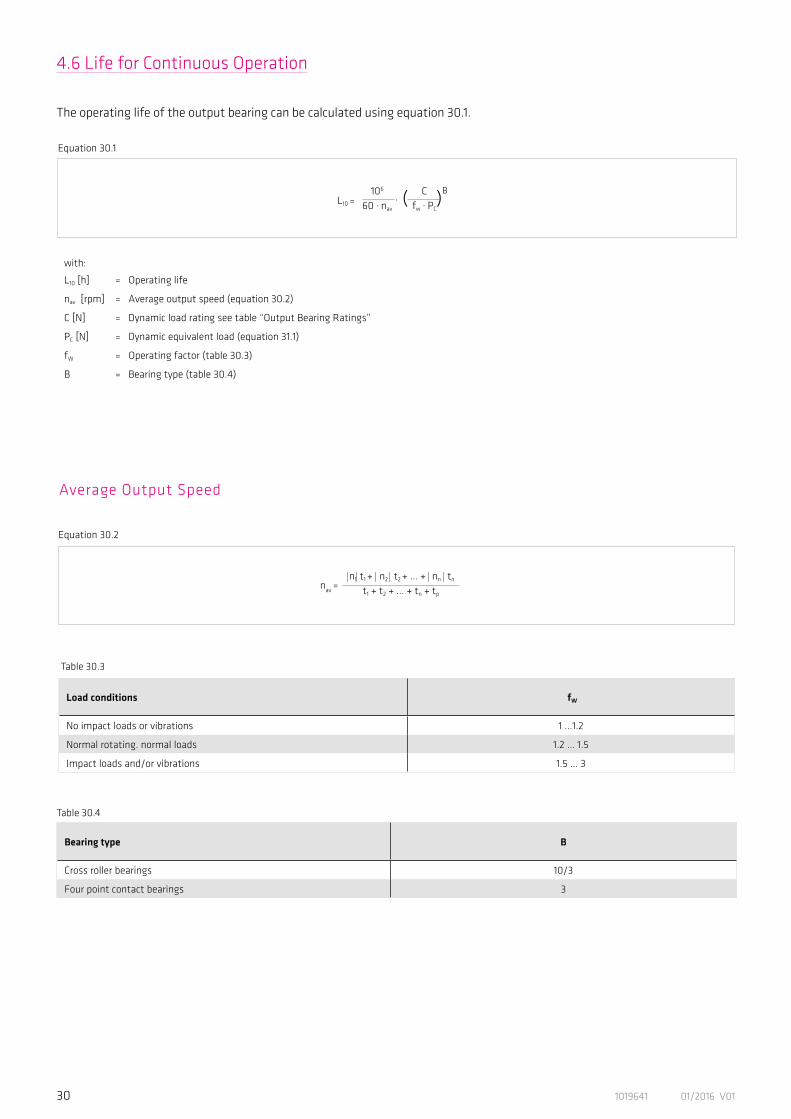
4.6 Life for Continuous Operation
The operating life of the output bearing can be calculated using equation 30.1.
with:
L10 [h] = Operating life
nav [rpm] = Average output speed (equation 30.2)
C [N] = Dynamic load rating see table “Output Bearing Ratings”
PC [N] = Dynamic equivalent load (equation 31.1)
fW = Operating factor (table 30.3)
B = Bearing type (table 30.4)
Average Output Speed
nav =|n1| t1 + | n2 | t2 + ... + | nn | tn
t1 + t2 + ... + tn + tp
Load conditions fW
No impact loads or vibrations 1 ...1.2
Normal rotating. normal loads 1.2 ... 1.5
Impact loads and/or vibrations 1.5 ... 3
Table 30.3
L10 =106
60 . nav
. ( )BCfw . PC
Equation 30.1
Equation 30.2
Bearing type B
Cross roller bearings 10/3
Four point contact bearings 3
Table 30.4

311019641 01/2016 V01
Dynamic Equivalent Load
Illustration 31.5
Table 31.4
Please note:Frx = represents the maximum radial force.Fax = represents the maximum axial force.tp = represents the pause time between cycles.
PC = x . Frav + + y . Faav
2Mdp
( )
Equation 31.1
Frav =|n1 | . t1
.( |Fr1 |)B +|n2 | . t2
.(|Fr2 |)B + ... + |nn | . tn
.( |Frn |)B
|n1 | . t1 + |n2 | . t2 + ... + |nn |. tn( )1/B
Equation 31.2
Faav = ( )1/B|n1| . t1 .( |Fa1 | )
B + |n2 | . t2
.( |Fa2 |)B + ... + |nn | . tn
.( |Fan | )B
|n1 | . t1 + |n2 | . t2 + ... +|nn | . tn
Equation 31.3
Load factors x y
1 0.45
0.67 0.67
Frav + 2 · M / dp
≤ 1.5Faav
Frav + 2 · M / dp
> 1.5Faav
with:
Frav [N] = Radial force (equation 31.2)
Faav [N] = Axial force (equation 31.3)
dp [m] = Pitch circle (see table 14.1)
x = Radial load factor (table 31.4)
y = Axial load factor (table 31.4)
M = Tilting moment
32 1019641 01/2016 V01
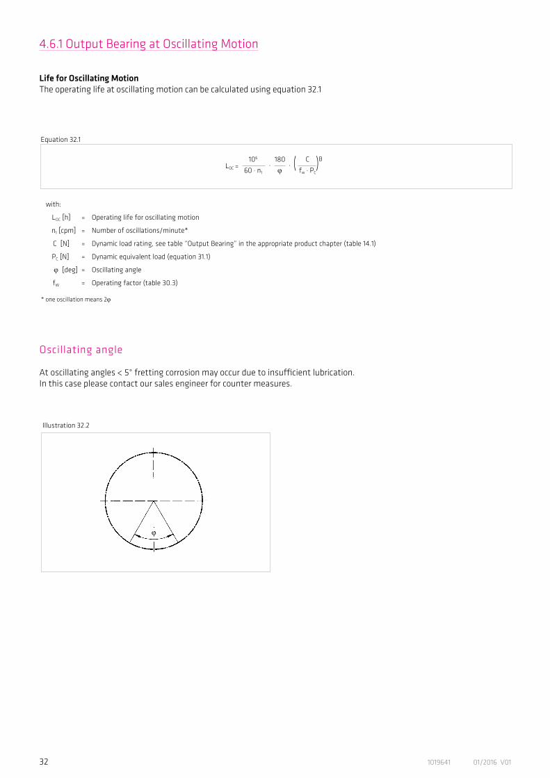
4.6.1 Output Bearing at Oscillating Motion
Life for Oscillating MotionThe operating life at oscillating motion can be calculated using equation 32.1
Oscillating angle
At oscillating angles < 5° fretting corrosion may occur due to insufficient lubrication. In this case please contact our sales engineer for counter measures.
with:
LOC [h] = Operating life for oscillating motion
n1 [cpm] = Number of oscillations/minute*
C [N] = Dynamic load rating, see table “Output Bearing” in the appropriate product chapter (table 14.1)
PC [N] = Dynamic equivalent load (equation 31.1)
ϕ [deg] = Oscillating angle
fW = Operating factor (table 30.3)
* one oscillation means 2ϕ
Equation 32.1
Illustration 32.2
LOC =106
60 . n1
. ( )B180
ϕ. C
fw . PC
331019641 01/2016 V01
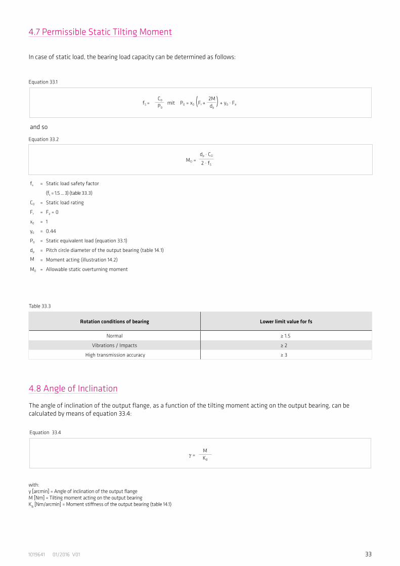
4.7 Permissible Static Tilting Moment
In case of static load, the bearing load capacity can be determined as follows:
Equation 33.4
γ =MKB
fs = Static load safety factor
(fs = 1.5 ... 3) (table 33.3)
C0 = Static load rating
Fr = Fa = 0
x0 = 1
y0 = 0.44
P0 = Static equivalent load (equation 33.1)
dp = Pitch circle diameter of the output bearing (table 14.1)
M = Moment acting (illustration 14.2)
M0 = Allowable static overturning moment
Rotation conditions of bearing Lower limit value for fs
Normal ≥ 1.5
Vibrations / Impacts ≥ 2
High transmission accuracy ≥ 3
Table 33.3
fS = ( ) C0
P0mit P0 = x0 Fr + + y0 . Fa
2Mdp
MO =dp . CO
2 . fS
and so
4.8 Angle of Inclination
The angle of inclination of the output flange, as a function of the tilting moment acting on the output bearing, can be calculated by means of equation 33.4:
Equation 33.1
Equation 33.2
with:y [arcmin] = Angle of inclination of the output flangeM [Nm] = Tilting moment acting on the output bearingKB [Nm/arcmin] = Moment stiffness of the output bearing (table 14.1)
34 1019641 01/2016 V01
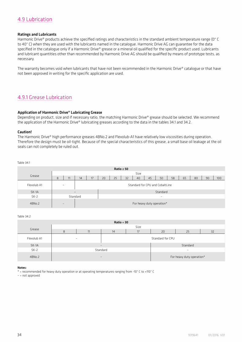
4.9 Lubrication
Ratings and LubricantsHarmonic Drive® products achieve the specified ratings and characteristics in the standard ambient temperature range (0° Cto 40° C) when they are used with the lubricants named in the catalogue. Harmonic Drive AG can guarantee for the dataspecified in the catalogue only if a Harmonic Drive® grease or a mineral oil qualified for the specific product used. Lubricants and lubricant quantities other than recommended by Harmonic Drive AG should be qualified by means of prototype tests, as necessary.
The warranty becomes void when lubricants that have not been recommended in the Harmonic Drive® catalogue or that have not been approved in writing for the specific application are used.
4.9.1 Grease Lubrication
Application of Harmonic Drive® Lubricating GreaseDepending on product, size and if necessary ratio, the matching Harmonic Drive® grease should be selected. We recommendthe application of the Harmonic Drive® lubricating greases according to the data in the tables 34.1 and 34.2.
Caution!The Harmonic Drive® high performance greases 4BNo.2 and Flexolub-A1 have relatively low viscosities during operation. Therefore the design must be oil-tight. Because of the special characteristics of this grease, a small base oil leakage at the oil seals can not completely be ruled out.
Table 34.1
Table 34.2
Notes:* = recommended for heavy duty operation or at operating temperatures ranging from -10° C to +110° C– = not approved
Ratio ≥ 50
GreaseSize
8 11 14 17 20 25 32 40 45 50 58 65 80 90 100
Flexolub A1 – Standard for CPU and CobaltLine
SK-1A – StandardSK-2 Standard –
4BNo.2 – For heavy duty operation*
Ratio = 30
Grease Size
8 11 14 17 20 25 32
Flexolub A1 – Standard for CPU
SK-1A – StandardSK-2 Standard –
4BNo.2 – For heavy duty operation*

351019641 01/2016 V01
Harmonic Drive® lubricating greases
TypeStandard Special
SK-1A SK-2 Flexolub A1 4BNo.2Operating temperature range 0° C ... +80° C 0° C ... +80° C -40° C ... +120° C -10° C ... +110° C
Base oil Mineral oil Mineral oil PAO / Ester oil Synthetic oil
Thickener Lithium soap Lithium soap Lithium soap Urea
Consistency class (NLGI) 2 2 1 1-2
Base oil viscosity (40° C; 100° C) 37; 5,9 mm2/St 37; 5,9 mm2/St 25; 5,2 mm2/St 50; 12 mm2/St
Drop point 197° C 198° C 180° C 247° C
Colour yellow green magenta pale yellow
Max. storage time in hermetically sealed container 5 years
Ease of sealing (safety against grease- or base oil leakage at the oil seals) + + + +/-
Notes: + = Good+/– = May be critical depending on design / mounting position / application, please contact Harmonic Drive AG
Table 35.1 gives some important information regarding Harmonic Drive® lubricating greases.
Table 35.1
Safety data sheets and technical data sheets for the Harmonic Drive® lubricants are available from Harmonic Drive AG.
36 1019641 01/2016 V01
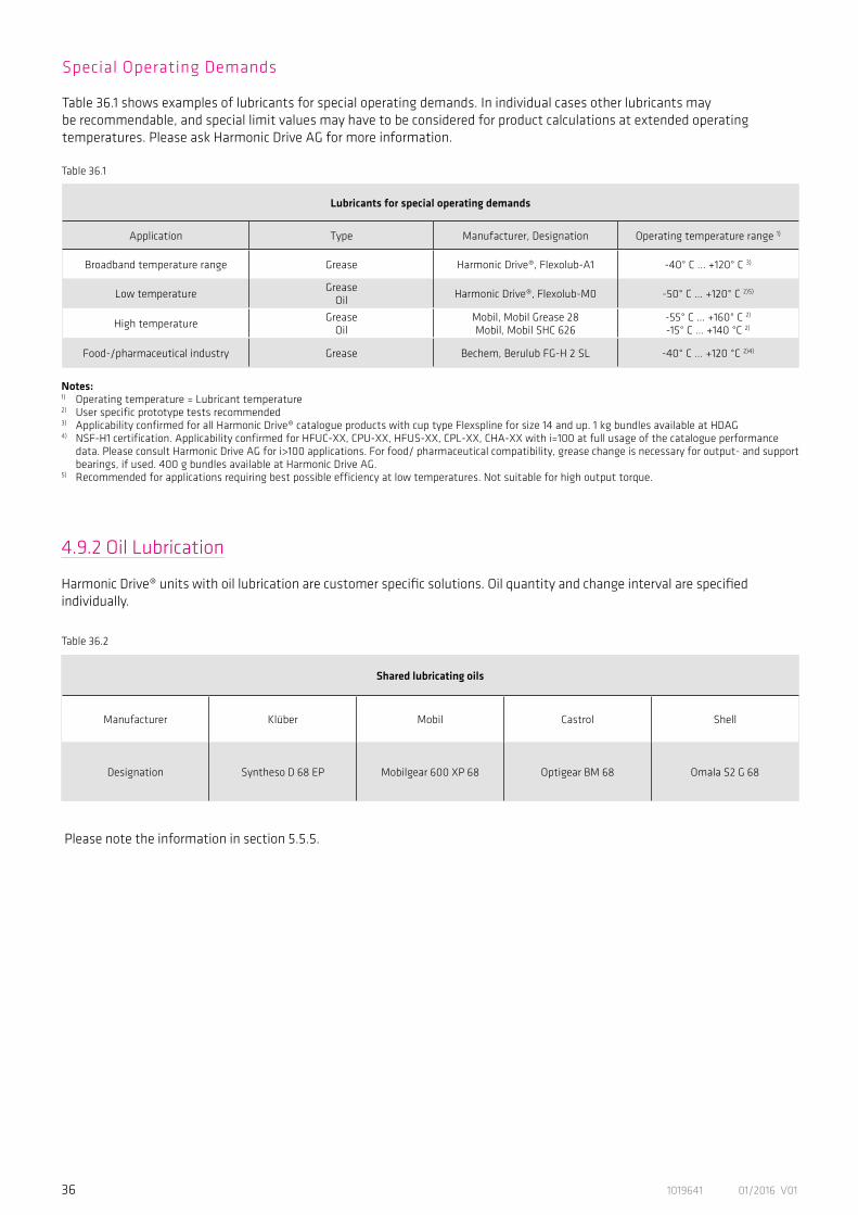
Table 36.1
Table 36.2
Notes: 1) Operating temperature = Lubricant temperature2) User specific prototype tests recommended3) Applicability confirmed for all Harmonic Drive® catalogue products with cup type Flexspline for size 14 and up. 1 kg bundles available at HDAG4) NSF-H1 certification. Applicability confirmed for HFUC-XX, CPU-XX, HFUS-XX, CPL-XX, CHA-XX with i=100 at full usage of the catalogue performance data. Please consult Harmonic Drive AG for i>100 applications. For food/ pharmaceutical compatibility, grease change is necessary for output- and support
bearings, if used. 400 g bundles available at Harmonic Drive AG.5) Recommended for applications requiring best possible efficiency at low temperatures. Not suitable for high output torque.
Lubricants for special operating demands
Application Type Manufacturer, Designation Operating temperature range 1)
Broadband temperature range Grease Harmonic Drive®, Flexolub-A1 -40° C ... +120° C 3)
Low temperature GreaseOil Harmonic Drive®, Flexolub-M0 -50° C ... +120° C 2)5)
High temperature GreaseOil
Mobil, Mobil Grease 28Mobil, Mobil SHC 626
-55° C ... +160° C 2)
-15° C ... +140 °C 2)
Food-/pharmaceutical industry Grease Bechem, Berulub FG-H 2 SL -40° C ... +120 °C 2)4)
Special Operating Demands
Table 36.1 shows examples of lubricants for special operating demands. In individual cases other lubricants maybe recommendable, and special limit values may have to be considered for product calculations at extended operatingtemperatures. Please ask Harmonic Drive AG for more information.
4.9.2 Oil Lubrication
Harmonic Drive® units with oil lubrication are customer specific solutions. Oil quantity and change interval are specified individually.
Shared lubricating oils
Manufacturer Klüber Mobil Castrol Shell
Designation Syntheso D 68 EP Mobilgear 600 XP 68 Optigear BM 68 Omala S2 G 68
Please note the information in section 5.5.5.
371019641 01/2016 V01
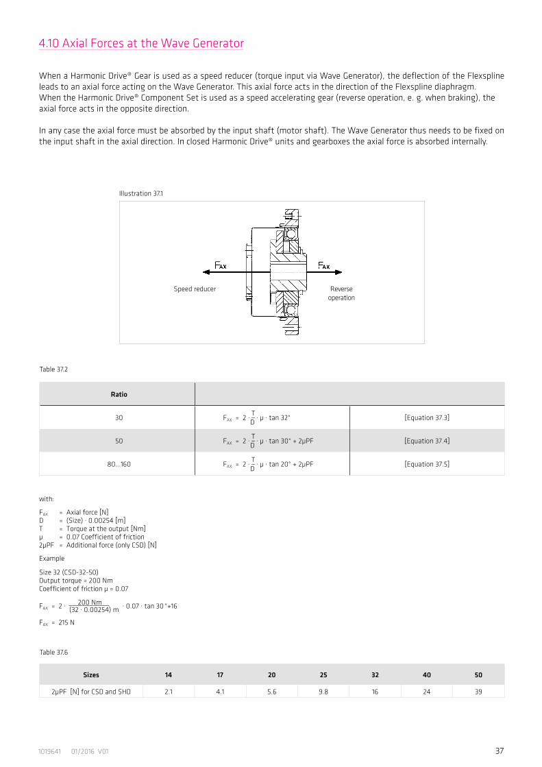
4.10 Axial Forces at the Wave Generator
When a Harmonic Drive® Gear is used as a speed reducer (torque input via Wave Generator), the deflection of the Flexspline leads to an axial force acting on the Wave Generator. This axial force acts in the direction of the Flexspline diaphragm.When the Harmonic Drive® Component Set is used as a speed accelerating gear (reverse operation, e. g. when braking), theaxial force acts in the opposite direction.
In any case the axial force must be absorbed by the input shaft (motor shaft). The Wave Generator thus needs to be fixed on the input shaft in the axial direction. In closed Harmonic Drive® units and gearboxes the axial force is absorbed internally.
Ratio
30 FAX = 2 · T _ D
· µ · tan 32° [Equation 37.3]
50 FAX = 2 · T _ D
· µ · tan 30° + 2µPF [Equation 37.4]
80...160 FAX = 2 · T _ D
· µ · tan 20° + 2µPF [Equation 37.5]
Table 37.2
Sizes 14 17 20 25 32 40 50
2µPF [N] for CSD and SHD 2.1 4.1 5.6 9.8 16 24 39
with:
FAX = Axial force [N] D = (Size) · 0.00254 [m] T = Torque at the output [Nm] µ = 0.07 Coefficient of friction 2µPF = Additional force (only CSD) [N]
Example
Size 32 (CSD-32-50)Output torque = 200 NmCoefficient of friction µ = 0.07
200 Nm FAX = 2 · (32 · 0.00254) m · 0.07 · tan 30 °+16
FAX = 215 N
Table 37.6
Illustration 37.1
Speed reducer Reverse operation
38 1019641 01/2016 V01
5.3 Assembly Information
Screws which have been tightened by the gear manufacturer must not be loosened.
ADVICE
5. Installation and Operation
5.1 Transport and Storage
Gears should be transported in the original packaging. If the gear is not put into service immediately on receipt, it should be stored in a dry area in the original packaging. The permissible storage temperature range is -20° C to +60° C.
5.2 Gear Condition at Delivery
The gears are generally delivered according to the dimensions indicated in the confirmation drawing.
Gears with Grease LubricationUnits are supplied with grease lubricant as standard.
Gears with Oil Lubrication Harmonic Drive® Units with oil lubrication are generally customer-specific solutions. Please follow the notes given on the confirmation drawing. The oil temperature during operation must not exceed 90° C. Oil must be filled into the unit by the customer as the standard delivery does not include any oil lubricant.
Oil Quantity The values specified in the confirmation drawing include the valid oil quantities to fill in. The oil quantity defined on the confirmation drawing must be obeyed in any case. Too much oil results in excessive heat production and early wear due to the thermal destruction of the oil. If the oil level is too low, this may lead to early wear as a result of lubricant deficiency.

391019641 01/2016 V01
Size 14 17 20 25 32 40
a 0.011 0.015 0.017 0.024 0.026 0.026
b0.017 0.020 0.020 0.024 0.024 0.032
(0.008) (0.010) (0.010) (0.012) (0.012) (0.012)
c0.030 0.034 0.044 0.047 0.050 0.063(0.016) (0.018) (0.019) (0.022) (0.022) (0.024)
Table 39.2 [mm]
In order for the new features of Harmonic Drive® Units to be exploited fully, it is essential that the tolerances according to table 39.2 are observed for the input assembly.
Illustration 39.1
Recommended shaft tolerances h6ER
ecom
men
ded
hous
ing
tole
ranc
es H
7
The values in brackets are the recommended tolerances for component sets featuring a Wave Generator without Oldham coupling. The Oldham coupling ser-ves to compensate for eccentricity of the input shaft and is available in the standard version. For the direct mounting of a Wave Generator without Oldham coupling (optional) on a motor shaft, the shaft tolerances should fulfill the DIN 42955 R standard.
5.4 Recommended Tolerances for Assembly
5.5 Lubrication
Harmonic Drive® Units are delivered ready for immediate installation. They are supplied with lifetime lubricant which is a high performance grease that meets the specific requirements of the Harmonic Drive® gears. It guarantees constant accuracy of the gears for their whole life. A re-lubrication of the Units is not necessary.
Illustration 39.3
5.5.1 Grease Lubrication
Units are supplied with standard grease lubricant. Illustration 39.3 shows the sections where lubrication is required and which are filled with grease lubrication at the time of delivery. If no special arrangements are made the specially developed high per-fomance grease 4BNo.2 is used. If any other grease is used this will be indicated on the customer drawing.
The following components are supplied with grease lubricant ex factory:Wave GeneratorCircular SplineFlexsplineOutput Bearing
40 1019641 01/2016 V01
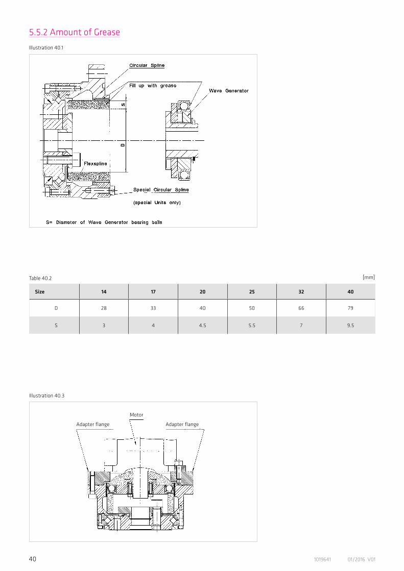
Size 14 17 20 25 32 40
D 28 33 40 50 66 79
S 3 4 4.5 5.5 7 9.5
5.5.2 Amount of Grease
Illustration 40.1
Table 40.2 [mm]
Illustration 40.3
D
Adapter flange Adapter flange
Motor
411019641 01/2016 V01
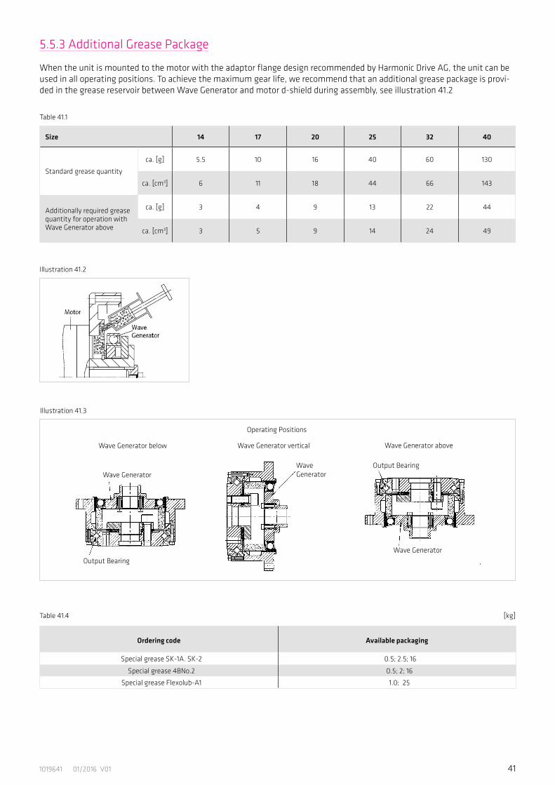
Table 41.1
Size 14 17 20 25 32 40
Standard grease quantity
ca. [g] 5.5 10 16 40 60 130
ca. [cm3] 6 11 18 44 66 143
Additionally required grease quantity for operation with Wave Generator above
ca. [g] 3 4 9 13 22 44
ca. [cm3] 3 5 9 14 24 49
Ordering code Available packaging
Special grease SK-1A. SK-2 0.5; 2.5; 16
Special grease 4BNo.2 0.5; 2; 16
Special grease Flexolub-A1 1.0; 25
Table 41.4 [kg]
5.5.3 Additional Grease Package
When the unit is mounted to the motor with the adaptor flange design recommended by Harmonic Drive AG, the unit can be used in all operating positions. To achieve the maximum gear life, we recommend that an additional grease package is provi-ded in the grease reservoir between Wave Generator and motor d-shield during assembly, see illustration 41.2
Illustration 41.2
Illustration 41.3
Wave Generator below Wave Generator vertical Wave Generator above
Operating Positions
Output Bearing
Output Bearing
Wave Generator
Wave GeneratorWave Generator

42 1019641 01/2016 V01
5.5.5 Oil Lubrication
Harmonic Drive® Units with oil lubrication are generally customer-specific solutions. Please follow the notes given on the con-firmation drawing and refer to section 4.9.2 for allowed oil types. The oil temperature during operation must not exceed 90°C. Oil must be filled into the unit by the customer as the standard delivery does not include any oil lubricant.
The values specified in the confirmation drawing include the valid oil quantities to fill in. The oil quantity defined on the confirmation drawing must be obeyed in any case. Too much oil results in excessive heat production and early wear due to the thermal destruction of the oil. If the oil level is too low, this may lead to early wear as a result of lubricant deficiency.
The first oil change is necessary after 100 hours of operation. Subsequent oil change intervals depend on the operating condi-tions, but should take place at intervals of approximately 1000 running hours.
To change the oil, the used oil must be drained completely and fresh oil must be filled in. Permitted oil types see in table 36.2. The mixture of lubricants of different specifications should generally be avoided.
5.5.4 Grease Change
To change the grease the component set should be completely disassembled and cleaned before regreasing. Fresh grease should be applied generously to the inside of the Flexspline, the Wave Generator bearing, the Oldham coupling and the teeth of the Cir-cular Spline and Flexspline.
In illustration 42.1 the grease change interval depending on the grease temperature is given. The number of allowable revolu-tions of the input shaft which represents the grease change interval can be estimated as shown in the example. This means, that for a temperature of SK-1A or SK-2 grease of 40°C a change should take place after approx. 8.5 x 10⁸ revolutions of the input shaft. All grease change data refers to rated speed and rated torque.
Illustration 42.1 Gleichung 42.2
LGT = Number of Wave Generator revolutions until grease change
LGTn = see diagram
TN = Rated torque
Tav = Average torque
LGT = LGTn. ( )3TN
Tav
1E+08
1E+09
1E+10
20 40 60 80 100 120 140
Grease Temperature [°C]
1E+10
1E+09
1E+08
Num
ber o
f W
G re
volu
tion
s
20 40 60 80 100 120 140
Flexolub A1
4B No. 2
SK1A, SK2
431019641 01/2016 V01
5.6 Preparation for Assembly
Assembly preparationThe gear assembly must be carried out very carefully and within a clean environment. Please make sure that during the assembly procedure no foreign particles enter the gear.
General informationClean, degrease and dry all mating surfaces to ensure an adequate coefficient of friction. The values given in table 8 are valid for 12.9 quality screws which must be tightened by means of a torque wrench. Locking devices such as spring washers or toothed washers should not be used.
Auxiliary materials for assemblyFor the assembly, we recommend the application of the following auxiliary materials or the use of those with similar characteristics. Please pay attention to the application guidelines given by the manufacturer. Auxiliary materials must not enter the gear.
Surface sealing• Loctite 5203• Loxeal 28-10Recommended for all mating surfaces, if the use of o-ring seals is not intended. Flanges provided with O-ring grooves must be sealed with sealing compound when a proper seal cannot be achieved using the O-ring alone.
Screw fixing• Loctite 243This adhesive ensures that the screw is fixed and also provides a good sealing effect. Loctite 243 is recommended for all screw connections.
Assembly paste• Klüber Q NB 50Recommended for o-rings which may come out of the groove during the assembly procedure. Before starting with the assembly you should spread some grease (which you can take from the gear) on all other o-rings.
Adhesives• Loctite 638Apply Loctite 638 to the connections between motor shaft and Wave Generator. You should make use of it only if this is specified in the confirmation drawing.
44 1019641 01/2016 V01
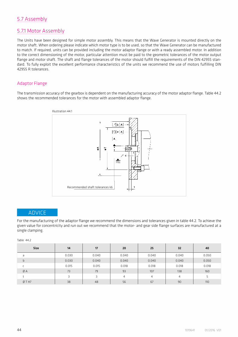
Size 14 17 20 25 32 40
a 0.030 0.040 0.040 0.040 0.040 0.050
b 0.030 0.040 0.040 0.040 0.040 0.050
c 0.015 0.015 0.018 0.018 0.018 0.018
Ø A 73 79 93 107 138 160
t 3 3 4 4 4 5
Ø T H7 38 48 56 67 90 110
5.7.1 Motor Assembly
The Units have been designed for simple motor assembly. This means that the Wave Generator is mounted directly on the motor shaft. When ordering please indicate which motor type is to be used, so that the Wave Generator can be manufactured to match. If required, units can be provided including the motor adaptor flange or with a ready assembled motor. In addition to the correct dimensioning of the motor, particular attention must be paid to the geometric tolerances of the motor output flange and motor shaft. The shaft and flange tolerances of the motor should fulfill the requirements of the DIN 42955 stan-dard. To fully exploit the excellent performance characteristics of the units we recommend the use of motors fulfilling DIN 42955 R tolerances.
Adaptor Flange
The transmission accuracy of the gearbox is dependent on the manufacturing accuracy of the motor adaptor flange. Table 44.2 shows the recommended tolerances for the motor with assembled adaptor flange.
Illustration 44.1
Recommended shaft tolerances k6
For the manufacturing of the adaptor flange we recommend the dimensions and tolerances given in table 44.2. To achieve the given value for concentricity and run out we recommend that the motor- and gear side flange surfaces are manufactured at a single clamping.
Table 44.2
ADVICE
5.7 Assembly
451019641 01/2016 V01
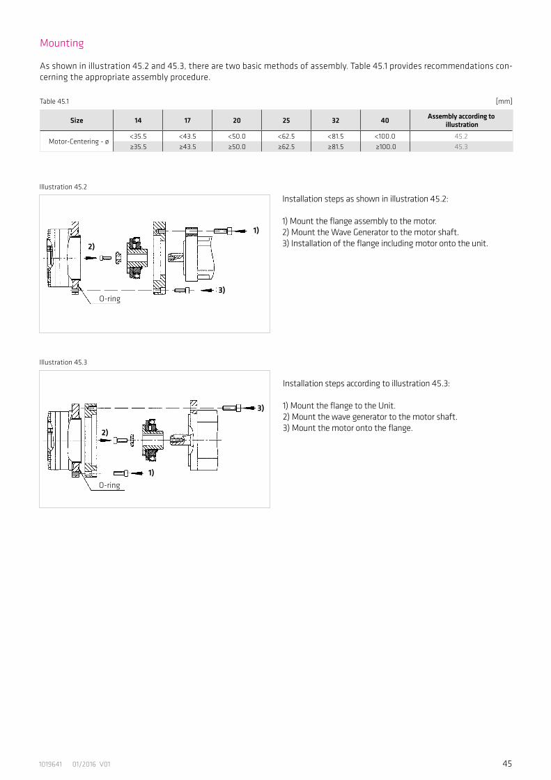
Table 45.1
Size 14 17 20 25 32 40 Assembly according to illustration
Motor-Centering - ø <35.5 <43.5 <50.0 <62.5 <81.5 <100.0 45.2≥35.5 ≥43.5 ≥50.0 ≥62.5 ≥81.5 ≥100.0 45.3
[mm]
As shown in illustration 45.2 and 45.3, there are two basic methods of assembly. Table 45.1 provides recommendations con-cerning the appropriate assembly procedure.
Mounting
Illustration 45.2
Illustration 45.3
Installation steps as shown in illustration 45.2:
1) Mount the flange assembly to the motor. 2) Mount the Wave Generator to the motor shaft. 3) Installation of the flange including motor onto the unit.2)
3)
1)
Installation steps according to illustration 45.3:
1) Mount the flange to the Unit. 2) Mount the wave generator to the motor shaft. 3) Mount the motor onto the flange.2)
3)
1)O-ring
O-ring
46 1019641 01/2016 V01
Principle of an Oldham Coupling
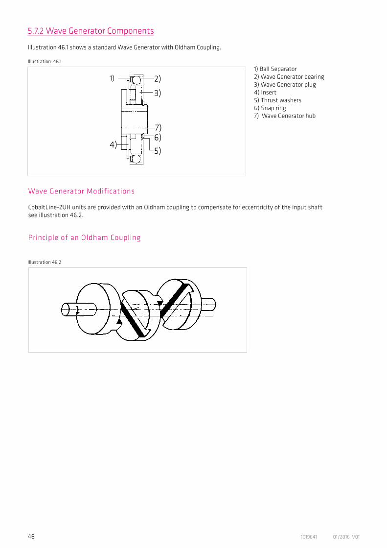
Wave Generator Modifications
CobaltLine-2UH units are provided with an Oldham coupling to compensate for eccentricity of the input shaft see illustration 46.2.
Illustration 46.2
1) 2)
7)6)
3)
5)4)
1) Ball Separator2) Wave Generator bearing3) Wave Generator plug4) Insert5) Thrust washers6) Snap ring7) Wave Generator hub
5.7.2 Wave Generator Components
Illustration 46.1 shows a standard Wave Generator with Oldham Coupling.
Illustration 46.1
471019641 01/2016 V01
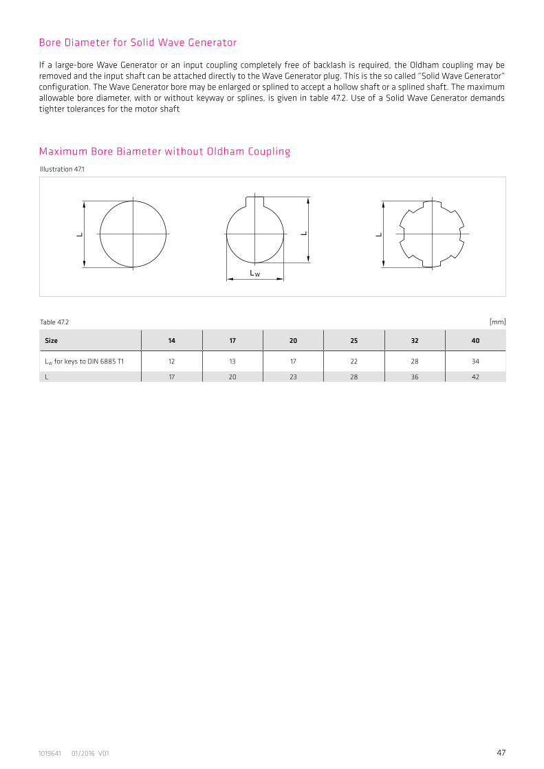
Illustration 47.1
Size 14 17 20 25 32 40
LW for keys to DIN 6885 T1 12 13 17 22 28 34
L 17 20 23 28 36 42
Table 47.2 [mm]
Bore Diameter for Solid Wave Generator
If a large-bore Wave Generator or an input coupling completely free of backlash is required, the Oldham coupling may be removed and the input shaft can be attached directly to the Wave Generator plug. This is the so called “Solid Wave Generator“ configuration. The Wave Generator bore may be enlarged or splined to accept a hollow shaft or a splined shaft. The maximum allowable bore diameter, with or without keyway or splines, is given in table 47.2. Use of a Solid Wave Generator demands tighter tolerances for the motor shaft
Maximum Bore Biameter without Oldham Coupling
48 1019641 01/2016 V01
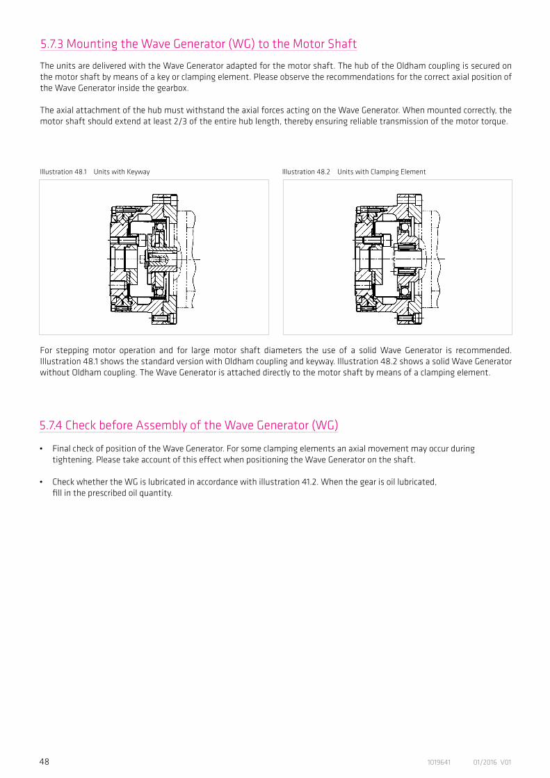
The units are delivered with the Wave Generator adapted for the motor shaft. The hub of the Oldham coupling is secured on the motor shaft by means of a key or clamping element. Please observe the recommendations for the correct axial position of the Wave Generator inside the gearbox.
The axial attachment of the hub must withstand the axial forces acting on the Wave Generator. When mounted correctly, the motor shaft should extend at least 2/3 of the entire hub length, thereby ensuring reliable transmission of the motor torque.
For stepping motor operation and for large motor shaft diameters the use of a solid Wave Generator is recommended. Illustration 48.1 shows the standard version with Oldham coupling and keyway. Illustration 48.2 shows a solid Wave Generator without Oldham coupling. The Wave Generator is attached directly to the motor shaft by means of a clamping element.
Illustration 48.2 Units with Clamping ElementIllustration 48.1 Units with Keyway
5.7.3 Mounting the Wave Generator (WG) to the Motor Shaft
5.7.4 Check before Assembly of the Wave Generator (WG)
• Final check of position of the Wave Generator. For some clamping elements an axial movement may occur during tightening. Please take account of this effect when positioning the Wave Generator on the shaft.
• Check whether the WG is lubricated in accordance with illustration 41.2. When the gear is oil lubricated, fill in the prescribed oil quantity.
491019641 01/2016 V01
Illustration 49.1
5.7.5 Assembly Control
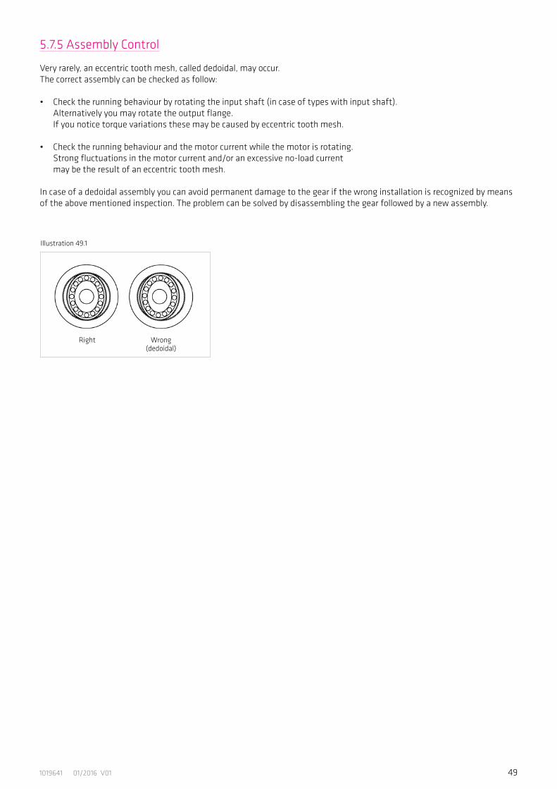
Very rarely, an eccentric tooth mesh, called dedoidal, may occur. The correct assembly can be checked as follow:
• Check the running behaviour by rotating the input shaft (in case of types with input shaft). Alternatively you may rotate the output flange. If you notice torque variations these may be caused by eccentric tooth mesh.
• Check the running behaviour and the motor current while the motor is rotating. Strong fluctuations in the motor current and/or an excessive no-load current may be the result of an eccentric tooth mesh.
In case of a dedoidal assembly you can avoid permanent damage to the gear if the wrong installation is recognized by means of the above mentioned inspection. The problem can be solved by disassembling the gear followed by a new assembly.
Right Wrong(dedoidal)
50 1019641 01/2016 V01
Size 14 17 20 25 32 40
Number of Bolts 8 8 8 10 12 10
Bolt Size M4 M4 M5 M5 M6 M8
Bolt pitch diameter [mm] 65 71 82 96 125 144
Tightening Torque [Nm] 4.5 4.5 9 9 15.3 37
Torque transmittingcapacity* [Nm] 182 196 365 538 1200 2100
Table 50.3
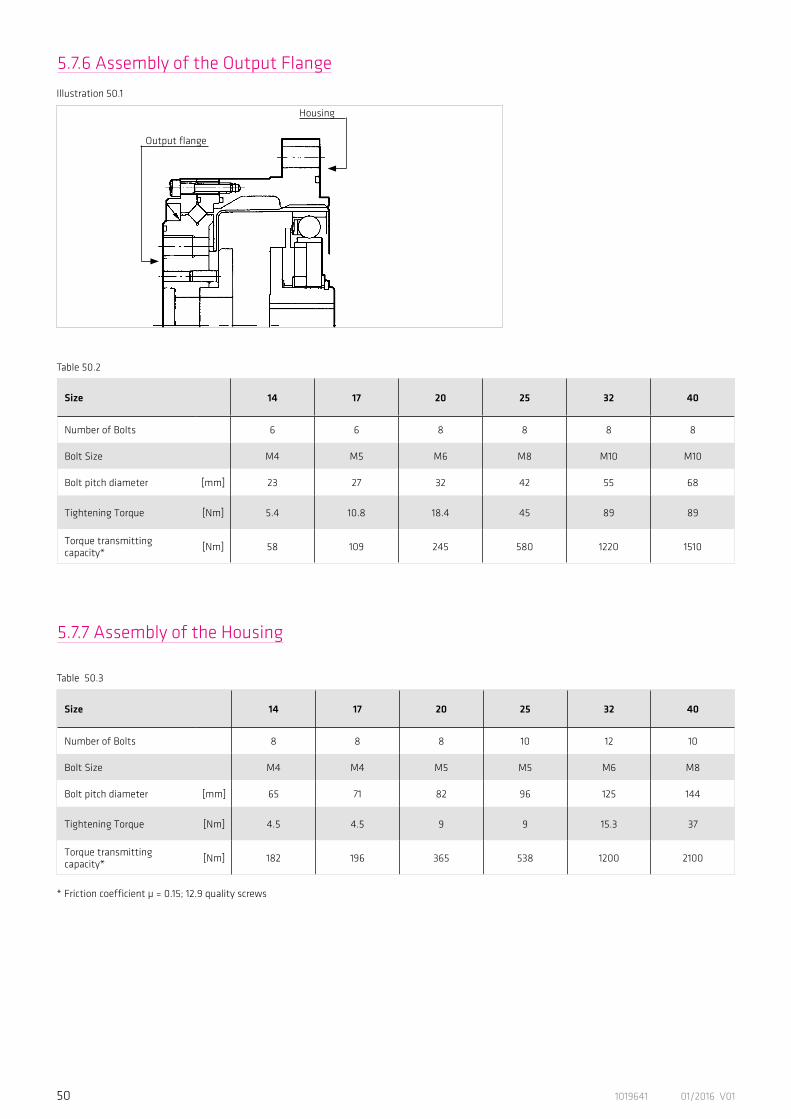
Size 14 17 20 25 32 40
Number of Bolts 6 6 8 8 8 8
Bolt Size M4 M5 M6 M8 M10 M10
Bolt pitch diameter [mm] 23 27 32 42 55 68
Tightening Torque [Nm] 5.4 10.8 18.4 45 89 89
Torque transmittingcapacity* [Nm] 58 109 245 580 1220 1510
Table 50.2
* Friction coefficient µ = 0.15; 12.9 quality screws
5.7.7 Assembly of the Housing
Illustration 50.1
Housing
Output flange
5.7.6 Assembly of the Output Flange

511019641 01/2016 V01
6. Decommissioning and Disposal
The gears, servo actuators and motors from Harmonic Drive AG contain lubricants for bearings and gears as well as electronic components and printed circuit boards. Since lubricants (greases and oils) are considered hazardous substances in accordance with health and safety regulations, it is necessary to dispose of the products correctly. Please ask for safety data sheet where necessary.


531019641 01/2016 V01
7. Glossary
7.1 Technical Data
AC Voltage constant kEM [Vrms / 1000 rpm]Effective value of the induced motor voltage measured at the motor terminals at a speed of 1000 rpm and an operating tempera-ture of 20° C.
Ambient operating temperature [° C]The intended operating temperature for the operation of the drive.
Average input speed (grease lubrication) nav (max) [rpm]Maximum permissible average gear input speed for grease lubrication.
Average input speed (oil lubrication) nav (max) [rpm]Maximum permissible average gear input speed for oil lubrication.
Average torque TA [Nm]When a variable load is applied to the gear, an average torque should be calculated for the complete operating cycle. This value should not exceed the specified TA limit.
Backlash (Harmonic Planetary gears) [arcmin]When subjected to the rated torque, Harmonic Planetary gears display characteristics shown in the hysteresis curve. When a torque is applied to the output shaft of the gear with the input shaft locked, the torque-torsion relationship can be measured at the output. Starting from point 0 the graph follows successive points A-B-A'-B'-A where the value B-B' is defined as the backlash or hysteresis.
Brake closing time tC [ms]Delay time to close the brake.
Brake current to hold IHBr [ADC]Current for applying the brake.
Brake current to open IOBr [ADC]Current required to open the brake.
Brake holding torque TBR [Nm]Torque the actuator can withstand when the brake is applied, with respect to the output.
Brake opening time tO [ms]Delay time for opening the brake. Brake voltage UBr [VDC]Terminal voltage of the holding brake.
Torque T +TN
Hysteresis loss/Backlash
TN = Rated torqueφ = Output angle
Torsion φ
54 1019641 01/2016 V01
Continuous stall current I0 [Arms]Effective value of the motor phase current to produce the stall torque.
Continuous stall torque T0 [Nm]Allowable actuator stall torque.
Demagnetisation current IE [Arms]Current at which rotor magnets start to demagnetise.
Dynamic axial load FA dyn (max) [N]With the bearing rotating, this is the maximum allowable axial load with no additional radial forces or tilting moments applied.
Dynamic load rating C [N]Maximum dynamic load that can be absorbed by the output bearing before permanent damage may occur.
Dynamic radial load FR dyn (max) [N]With the bearing rotating, this is the maximum allowable radial load with no additional axial forces or tilting moments applied.
Dynamic tilting moment Mdyn (max) [Nm]With the bearing rotating, this is the maximum allowable tilting moment with no additional axial forces or radial forces applied.
Electrical time constant τe [s]The electrical time constant is the time required for the current to reach 63% of its final value.
Hollow shaft diameter dH [mm]Free inner diameter of the continuous axial hollow shaft.
Inductance (L-L) LL-L [mH]Terminal inductance calculated without taking into account the magnetic saturation of the active motor parts.
Lost Motion (Harmonic Drive® Gearing) [arcmin]Harmonic Drive® Gearing exhibits zero backlash in the teeth. Lost motion is the term used to characterise the torsional stiffness in the low torque region.
The illustration shows the angle of rotation ϕ measured against the applied output torque as a hysteresis curve with the Wave Generator locked. The lost motion measurement of the gear is taken with an output torque of about ± 4% of the rated torque.
Maximum current Imax [A]The maximum current is the maximum current that can be applied for a short period.
Torsionφ
Torque T
~ +4%TN~ -4%TN
Lost
Mot
ion
φ1 ; φ2
φ1‘ ; φ2‘
551019641 01/2016 V01
Maximum DC bus voltage UDC (max) [VDC]The maximum DC bus power supply for the correct operation of the actuator. This value may only be exceeded for a short period during the braking or deceleration phase.
Maximum hollow shaft diameter dH (max) [mm]For gears with a hollow shaft, this value is the maximum possible diameter of the axial hollow shaft.
Maximum input speed (grease lubrication) nin (max) [rpm]Maximum allowable input speed with grease lubrication.
Maximum input speed (oil lubrication) nin (max) [rpm]Maximum allowable input speed for gearing with oil lubrication.
Maximum motor speed nmax [rpm]The maximum allowable motor speed.
Maximum output speed nmax [rpm]The maximum output speed. Due to heating issues, this may only be momentarily applied during the operating cycle. The maximum output speed can occur any number of times as long as the calculated average speed is within the permissible continuous operation duty cycle.
Maximum output torque Tmax [Nm]Specifies the maximum allowable acceleration and deceleration torques. For highly dynamic processes, this is the maximum torque available for a short period. The maximum torque can be parameterised by the control unit where the maximum current can be limited. The maximum torque can be applied as often as desired, as long as the calculated average torque is within the permissible continuous operation duty cycle.
Maximum power Pmax [W]Maximum power output.
Mechanical time constant τm [s]The mechanical time constant is the time required to reach 63% of its maximum rated speed in a no-load condition.
Momentary peak torque TM [Nm]In the event of an emergency stop or collision, the Harmonic Drive® Gearing may be subjected to a brief collision torque. The magnitude and frequency of this collision torque should be kept to a minimum and under no circumstances should the collision torque occur during the normal operating cycle.
Moment of inertia J [kgm²]Mass moment of inertia at motor side.
Moment of inertia Jin [kgm²]Mass moment of inertia of the gearing with respect to the input.
Moment of inertia Jout [kgm2]Mass moment of inertia with respect to the output.

56 1019641 01/2016 V01
Motor terminal voltage (Fundamental wave only) UM [Vrms]Required fundamental wave voltage to achieve the specified performance. Additional power losses can lead to restriction of the maximum achievable speed.
Number of pole pairs pNumber of magnetic pole pairs on the rotor of the motor.
Offset R [mm]Distance between output bearing and contact point of the load.
Pitch circle diameter dp [mm]Pitch circle diameter of the output bearing rolling elements.
Protection IPThe degree of protection according to EN 60034-5 provides suitability for various environmental conditions.
Rated current IN [A]RMS value of the sinusoidal current when driven at rated torque and rated speed.
Rated motor speed nN [rpm]The motor speed which can be continuously maintained when driven at rated torque TN, when mounted on a suitably dimensi-oned heat sink.
Rated power PN [W]Output power at rated speed and rated torque.
Rated speed nN [rpm], MechanicalThe rated speed is a reference speed for the calculation of the gear life. When loaded with the rated torque and running at rated speed the gear will reach the expected operating life L50. The speed nN is not used for dimensioning the gear.
Rated torque TN [Nm], ServoThe output torque which can be continuously transmitted when driven at rated input speed, when mounted on a suitably dimensioned heat sink.
Rated torque TN [Nm], MechanicalThe rated torque is a reference torque for the calculation of the gear life. When loaded with the rated torque and running at rated speed the gear will reach the average life L50. The rated torque TN is not used for the dimensioning of the gear.
Product series nN
CobaltLine®, HFUC, HFUS, CSF, CSG, CSD, SHG, SHD 2000
PMG size 5 4500
PMG size 8 to 14 3500
HPG, HPGP, HPN 3000
[rpm]
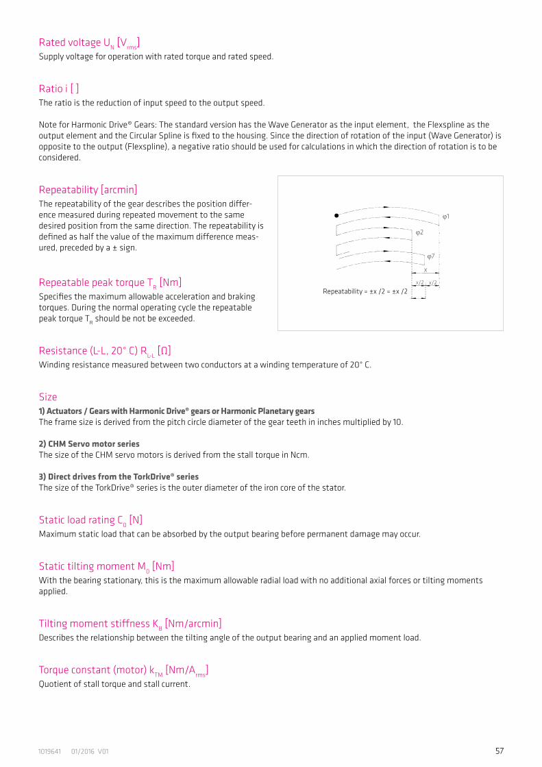
571019641 01/2016 V01
Rated voltage UN [Vrms]Supply voltage for operation with rated torque and rated speed.
Ratio i [ ]The ratio is the reduction of input speed to the output speed.
Note for Harmonic Drive® Gears: The standard version has the Wave Generator as the input element, the Flexspline as the output element and the Circular Spline is fixed to the housing. Since the direction of rotation of the input (Wave Generator) is opposite to the output (Flexspline), a negative ratio should be used for calculations in which the direction of rotation is to be considered.
Repeatability [arcmin]The repeatability of the gear describes the position differ-ence measured during repeated movement to the same desired position from the same direction. The repeatability is defined as half the value of the maximum difference meas-ured, preceded by a ± sign.
Repeatable peak torque TR [Nm]Specifies the maximum allowable acceleration and braking torques. During the normal operating cycle the repeatable peak torque TR should be not be exceeded.
Resistance (L-L, 20° C) RL-L [Ω]Winding resistance measured between two conductors at a winding temperature of 20° C.
Size1) Actuators / Gears with Harmonic Drive® gears or Harmonic Planetary gearsThe frame size is derived from the pitch circle diameter of the gear teeth in inches multiplied by 10.
2) CHM Servo motor seriesThe size of the CHM servo motors is derived from the stall torque in Ncm.
3) Direct drives from the TorkDrive® seriesThe size of the TorkDrive® series is the outer diameter of the iron core of the stator.
Static load rating C0 [N]Maximum static load that can be absorbed by the output bearing before permanent damage may occur.
Static tilting moment M0 [Nm]With the bearing stationary, this is the maximum allowable radial load with no additional axial forces or tilting moments applied.
Tilting moment stiffness KB [Nm/arcmin]Describes the relationship between the tilting angle of the output bearing and an applied moment load.
Torque constant (motor) kTM [Nm/Arms]Quotient of stall torque and stall current.
Repeatability = ±x /2 = ±x /2
φ1
φ7
φ2
x
x/2 x/2
58 1019641 01/2016 V01
Torque constant (output) kTout [Nm/Arms]Quotient of stall torque and stall current, taking into account the transmission losses.
Torsional stiffness (Harmonic Drive® Gears) K3 [Nm/rad]The amount of elastic rotation at the output for a given torque with the Wave Generator blocked. The torsional stiffness K3 describes the stiffness above a defined reference torque where the stiffness is almost linear.
The value given for the torsional stiffness K3 is an average that has been determined during numerous tests. The limit torques T1 and T2 and calculation example for the total tor-sional angle can be found in sections 3 and 4 of this docu-mentation.
Torsional stiffness (Harmonic Planetary gears) K [Nm/rad]The amount of elastic rotation at the output for a given torque and blocked input shaft. The torsional rigidity of the Harmonic Planetary gear describes the rotation of the gear above a reference torque of 15% of the rated torque. In this area the torsional stiffness is almost linear.
Transmission accuracy [arcmin]The transmission accuracy of the gear represents the linear-ity error between input and output angle. The transmission accuracy is measured for one complete output revolution using a high resolution measurement system. The measure-ments are carried out without direction reversal. The trans-mission accuracy is defined as the sum of the maximum positive and negative differences between the theoretical and actual output rotation angles.
Weight m [kg]The weight specified in the catalog is the net weight without packing and only applies to standard versions.
K1
K2
K3
0 T2
Torsionφ
φ2
φ1
T1
Torque T
K1, K2, K3 = Torsional stiffness, w = Output angleφ1 = Torsion angle, with output torque T1
φ2 = Torsion angle, with output torque T2
TN = Rated torqueφ = Output angle
Acc
urac
y
Tran
smis
sion
ac
cura
cy
360° Output angle

591019641 01/2016 V01
7.2 Labelling, Guidelines and Regulations
CE-MarkingWith the CE marking, the manufacturer or EU importer declares in accordance with EU regulation, that by affixing the CE mark the product meets the applicable requirements in the harmonization legislation established the Community.
REACH RegulationREACH is a European Community Regulation on chemicals. REACH stands forRegistration, Evaluation, Authorization and Restriction of Chemicals.
RoHS EU DirectiveThe RoHS EU Directive on the restriction of the use of certain hazardous substances in electrical and electronic equipment.
REACHVerordnungNr. 1907/2006

DeutschlandHarmonic Drive AGHoenbergstraße 1465555 Limburg/Lahn
Subject to technical changes.T +49 6431 5008-0F +49 6431 5008-119
01/2
016
10
1964
1 V0
1
Related Documents