E NGINEERED W OOD C ONSTRUCTION G UIDE THE ENGINEERED WOOD ASSOCIATION APA

Welcome message from author
This document is posted to help you gain knowledge. Please leave a comment to let me know what you think about it! Share it to your friends and learn new things together.
Transcript

ENGINEERED WOODCONSTRUCTION GUIDE
THE ENGINEEREDWOOD ASSOCIATION
APA

Be ConstructiveWOOD
Wood is the right choice for a host of construction applications. It is theearth’s natural, energy efficient and renewable building material.
Engineered wood is a better use of wood. It uses less wood to make morewood products. That’s why using APA trademarked I-joists, glued laminated
timbers, laminated veneer lumber, plywood and oriented strand board is constructive ... for the environment, for innovative design, and for strong, durable buildings.
A few facts about wood.■ We’re not running out of trees. One-third of the United States land base– 731 million acres – is covered by forests. About two-thirds of that 731million acres is suitable for repeated planting and harvesting of timber. Butonly about half of the land suitable for growing timber is open to logging.Most of that harvestable acreage also is open to other uses, such ascamping, hiking, and hunting. Forests fully cover one-half of Canada’s land mass. Of thisforestland, nearly half is considered productive, or capable of producing timber on asustained yield basis. Canada has the highest per capita accumulation of protected naturalareas in the world – areas including national and provincial parks.
■ We’re growing more wood every day. American landowners plant morethan two billion trees every year. In addition, millions of trees seednaturally. The forest products industry, which comprises about 15 percentof forestland ownership, is responsible for 41 percent of replanted forestacreage. That works out to more than one billion trees a year, or about
three million trees planted every day. This high rate of replanting accounts for the fact thateach year, 27 percent more timber is grown than is harvested. Canada’s replanting recordshows a fourfold increase in the number of trees planted between 1975 and 1990.
■ Manufacturing wood is energy efficient.Wood products made up 47 percent of allindustrial raw materials manufactured in theUnited States, yet consumed only 4 percentof the energy needed to manufacture allindustrial raw materials, according toa 1987 study.
■ Constructive news for a healthy planet. For every ton of wood grown, a young forest produces 1.07 tons of oxygen and absorbs 1.47 tons ofcarbon dioxide.
Wood. It’s the constructive choice for the environment.
Percent of Percent ofMaterial Production Energy Use
Wood 47 4
Steel 23 48
Aluminum 2 8
NOTICE:The recommendations inthis guide apply only topanels that bear the APAtrademark. Only panelsbearing the APA trademarkare subject to theAssociation’s qualityauditing program.
RATED SHEATHING
EXPOSURE 1SIZED FOR SPACING32/16 15/32 INCH
000PS 1-95 C-D PRP-108
THE ENGINEERED
WOOD ASSOCIATIONAPA
©20
01 A
PA –
TH
E EN
GIN
EERE
D W
OO
D A
SSO
CIA
TIO
N •
ALL
RIG
HTS
RES
ERVE
D. •
AN
Y C
OPY
ING
, MO
DIF
ICAT
ION
, DIS
TRIB
UTI
ON
OR
OTH
ER U
SE O
F TH
IS P
UBL
ICAT
ION
OTH
ER T
HA
N A
S EX
PRES
SLY
AUTH
ORI
ZED
BY
APA
IS P
ROH
IBIT
ED B
Y TH
E U
.S. C
OPY
RIG
HT
LAW
S.

PA engineered wood products are used in a wide range
of construction applications. Time-tested panel products
are used in traditional wood-frame construction and in
combination with other engineered wood products and systems.
For low in-place cost, versatility, and superior performance,
APA engineered wood systems are simply hard to beat.
This guide from APA – The Engineered Wood Association is
designed as a reference manual for engineered wood specifiers
and users in both residential and commercial construction. It
contains up-to-date information on APA Performance Rated
Panels, glulam, I-joists, specification practices, floor, wall and
roof systems, diaphragms and shear walls, fire-rated systems
and methods of finishing.
If what you want to know about engineered wood construction
systems isn’t fully explained here, chances are it is in one of
our many other publications. Simply write for the appropriate
title or titles cited throughout this publication. Product and
application information can also be found on the APA web site,
at www.apawood.org. Or, for individual assistance with specific
design questions or problems, contact the APA Product Support
Help Desk or the nearest APA regional field office listed on the
back cover.
A

GUIDE TO ENGINEERED WOOD PRODUCTS . . . . . . . . . . . . .4
Product Selection, Specification, and Handling . . . . . . . . . . . . . . . . . . .4
PANEL SELECTION ANDSPECIFICATION . . . . . . . . . . . . . . . . .5
Manufacturing and Performance Standards . . . . . . . . . . . .5
Grade Designations . . . . . . . . . . . . . . . .5Sanded, Unsanded and
Touch-Sanded Panels . . . . . . . . . . . . . .5Bond Classificiation . . . . . . . . . . . . . . . .6Group Number . . . . . . . . . . . . . . . . . . .6Span Ratings . . . . . . . . . . . . . . . . . . . .11How To Order APA Panels . . . . . . . . . . .11Grade Availability . . . . . . . . . . . . . . . . .12Metric Conversions . . . . . . . . . . . . . . . .12Panel Specification Guide . . . . . . . . .12Panel Storage and Handling . . . . . . .17
GLULAM SELECTION ANDSPECIFICATION . . . . . . . . . . . . . . . .18
Balanced and Unbalanced Beams . . . . .18Allowable Design Properties . . . . . . . . .18Sizes . . . . . . . . . . . . . . . . . . . . . . . . . .18Appearance Classification . . . . . . . . . . .18Section Properties and Capacities . . . . .19Camber . . . . . . . . . . . . . . . . . . . . . . . .19Trademarks and Acceptances . . . . . . . .20Specification Guide for
Structural Glued Laminated Timber (Glulam) . . . . . . . . . . . . . . .20
Glulam Beam Storage and Handling . . . . . . . . . . . . . . . . .21
I-JOISTS SELECTION ANDSPECIFICATION . . . . . . . . . . . . . . . .22
APA PRI-400 . . . . . . . . . . . . . . . . . . . . .22Residential Floor Spans . . . . . . . . . . . . .22Specifying APA Performance
Rated I-Joists . . . . . . . . . . . . . . . . .23I-Joist Storage and Handling . . . . . .25
FLOOR CONSTRUCTION . . . . . . . . .26APA Rated Sturd-I-Floor . . . . . . . . . . . .26The Code Plus Floor . . . . . . . . . . . . . . .29Sturd-I-Floor 32 oc and 48 oc . . . . . . . .29APA Performance Rated Rim Board . . . .29The APA Glued Floor System . . . . . . . . .30APA Panel Subflooring . . . . . . . . . . . . .32Lightweight Concrete
Over APA Panels . . . . . . . . . . . . . . . .33APA Plywood Underlayment . . . . . . . . .33Hardwood Flooring Over
APA Panel Subfloors . . . . . . . . . . . . . .34Ceramic Tile Over
APA Plywood Floors . . . . . . . . . . . . . .35APA Panel Stair Treads and Risers . . . . .36Heavy Duty Plywood Floors . . . . . . . . . .36
WALL CONSTRUCTION . . . . . . . . . .38APA Sturd-I-Wall . . . . . . . . . . . . . . . . . .38APA Panel and Lap Siding Over
Nailable Sheathing . . . . . . . . . . . . . .40APA Panel Wall Sheathing . . . . . . . . . . .42The Code Plus Wall . . . . . . . . . . . . . . .43APA Sheathing Under Stucco . . . . . . . . .44Siding Joint Details . . . . . . . . . . . . . . . .44APA Rated Siding Patterns
and Grades . . . . . . . . . . . . . . . . . . .46Finishing Plywood for
Exterior Exposure . . . . . . . . . . . . . . . .46Interior Paneling . . . . . . . . . . . . . . . . . .49Panel Backing . . . . . . . . . . . . . . . . . . . .49APA Panel Shear Walls . . . . . . . . . . . . .50
ROOF CONSTRUCTION . . . . . . . . . .52APA Panel Roof Sheathing . . . . . . . . . . .52The Code Plus Roof . . . . . . . . . . . . . . .52Preframed Roof Panels . . . . . . . . . . . . .54Long Span Systems . . . . . . . . . . . . . . . .56Plywood Under Special Coatings . . . . . .56APA Panel Soffits . . . . . . . . . . . . . . . . . .57APA Panel Roof Diaphragms . . . . . . . . .59
BUILDING REQUIREMENTS ANDRELATED PANEL SYSTEMS . . . . .61
Fire-resistant Construction . . . . . . . . . . .61Wind-resistive Roofs . . . . . . . . . . . . . . .64Noise Transmission Control . . . . . . . . . .65Energy Conservation . . . . . . . . . . . . . . .67Condensation: Its Cause and Control . .68Thermal Resistance of
Wood Structural Panels . . . . . . . . . . .69
RELATED PANEL SYSTEMS . . . . . . . . .69The Permanent Wood Foundation . . . . .69Plywood for Outdoor Decks . . . . . . . . .69Plywood for Concrete Forming . . . . . . .69Structural Insulated Panels . . . . . . . . . . .70APA Panels Over Metal Framing . . . . . .70APA Panel Systems
Over Concrete Slabs . . . . . . . . . . . . .71Special Floor Surfacing . . . . . . . . . . . . .71
ADDITIONAL INFORMATION . . . .71About APA – The Engineered Wood
Association and Engineered Wood Systems . . . . . . . . . . . . . . . . . .71
CONTENTS
GUIDE TO
ENGINEERED WOOD
PRODUCTS
Product Selection, Specification, and HandlingThe evolution of engineered woodproducts over the past few decades has greatly expanded building optionsand methods in all forms of residentialand commercial construction. Thenext 21 pages of this APA Design/Construction guide provide productinformation and specification recom-mendations for several of the mostcommon engineered wood products –plywood, oriented strand board, composite panels, glulam, and I-joists.Other engineered wood products thatare often used in the constructionsystems described in this guide includerim board and laminated veneer lumber (LVL).
“Engineered wood” describes woodproducts that are engineered for struc-tural applications. Having been usedsince the 1940s, plywood is consideredby many to be the original engineeredwood product. All glued engineeredwood products are made by combin-ing wood strands, veneers, lumber orother wood fiber with glue to form alarge composite structural unit. Theyare designed and manufactured tomaximize the natural strength andstiffness characteristics of wood byorienting the wood veneers, strands orlaminations and by combining woodwith durable adhesives.

5
veneer species and thickness, etc., are inmany instances identical to panel gradesas defined in Product Standard PS 1-95.
Typical APA Performance Rated Paneltrademarks are illustrated and explainedon page 6.
Grade DesignationsStructural panel grades are generallyidentified in terms of the veneer gradeused on the face and back of the panel(e.g., A-B, B-C, etc.), or by a name sug-gesting the panel’s intended end use(e.g., APA RATED SHEATHING, APARATED STURD-I-FLOOR, etc.). SeeTables 2-4.
Veneer grades define veneer appearancein terms of natural unrepaired growthcharacteristics and allowable numberand size of repairs that may be madeduring manufacture. See Table 1.The highest quality commonly availableveneer grade is A. The minimum gradeof veneer permitted in Exterior plywoodis C-grade. D-grade veneer is used inpanels intended for interior use or applications protected from long-termexposure to weather.
Sanded, Unsanded and Touch-Sanded PanelsPanels with B-grade or better veneerfaces are always sanded smooth inmanufacture to fulfill the requirementsof their intended end use – applicationssuch as cabinets, shelving, furniture,built-ins, etc. APA RATED SHEATHINGpanels are unsanded since a smoothsurface is not a requirement of theirintended end use. Still other panels –APA UNDERLAYMENT, APA RATEDSTURD-I-FLOOR, APA C-D PLUGGED,and APA C-C PLUGGED – require onlytouch sanding for “sizing” to make thepanel thickness more uniform.
Unsanded and touch-sanded panels,and panels with B-grade or better veneeron one side only, usually carry the APAtrademark on the panel back. Panelswith both sides of B-grade or betterveneer, or with special overlaid surfaces(such as HIGH DENSITY OVERLAY)usually carry the APA trademark on thepanel edge.
(a) The National Evaluation Service is sponsoredjointly by two model code organizations – theBuilding Officials and Code AdministratorsInternational, promulgators of the NationalBuilding Code and the Southern Building CodeCongress International, promulgators of theStandard Building Code. A third model codeorganization is the International Conference ofBuilding Officials, promulgators of the UniformBuilding Code. See National Evaluation ServiceReport No. NER-108 or ICBO ER-5681 for allow-able values and/or conditions of use concerningpanel material presented in this brochure. It issubject to reexamination, revisions, and possiblecancellation.
HUD recognition of wood-based APA PerformanceRated Panels is contained in Use of MaterialsBulletin UM-40.
Manufacturing and Performance StandardsPanels for construction and industrialapplications can be manufactured in a variety of ways – as plywood (cross-laminated wood veneer), as composite panels (veneer faces bondedto wood strand cores), or as orientedstrand board (OSB).
Some plywood panels are manufacturedunder the detailed manufacturing speci-fications or under the performance test-ing provisions of Voluntary ProductStandard PS 1-95 for Construction andIndustrial Plywood, developed coopera-tively by the plywood industry and theU.S. Department of Commerce. Otherplywood panels, however, as well ascomposite and OSB panels, aremanufactured under the provisions ofAPA PRP-108, Performance Standardsand Policies for Structural-Use Panels, or under Voluntary Product StandardPS 2-92, Performance Standard forWood-Based Structural-Use Panels, that establish performance criteria forspecific designated construction applications.
These APA Performance Rated Panels are easy to use and specify because therecommended end use and maximumsupport spacings are clearly indicatedin the APA trademark. By broadeningthe range of panel configuration andcomposition, APA Performance RatedPanels allow more efficient use of rawmaterials. APA PRP-108 PerformanceStandards are recognized by the NationalEvaluation Service, the InternationalConference of Building Officials (ICBO)and HUD.(a) PRP-108, PS-1 and/or thePS-2 grade conformance where applica-ble are given in the lower portion of theAPA trademark. Plywood panels,depending on glueline classification,
TABLE 1
VENEER GRADES
A Smooth, paintable. Not more than18 neatly made repairs, boat,sled, or router type, and parallel tograin, permitted. Wood or syn-thetic repairs permitted. May beused for natural finish in lessdemanding applications.
B Solid surface. Shims, sled or routerrepairs, and tight knots to 1 inchacross grain permitted. Wood orsynthetic repairs permitted. Someminor splits permitted.
C Improved C veneer with splits lim-ited to 1/8-inch width and knot-holes or other open defects limitedto 1/4 x 1/2 inch. Wood or syn-thetic repairs permitted. Admitssome broken grain.
C Tight knots to 1-1/2 inch.Knotholes to 1 inch across grainand some to 1-1/2 inch if totalwidth of knots and knotholes iswithin specified limits. Synthetic orwood repairs. Discoloration andsanding defects that do not impairstrength permitted. Limited splitsallowed. Stitching permitted.
D Knots and knotholes to 2-1/2-inchwidth across grain and 1/2 inchlarger within specified limits.Limited splits are permitted.Stitching permitted. Limited to Exposure 1 or Interior panels.
Plugged
PANEL SELECTION AND SPECIFICATION

Bond ClassificationAPA trademarked panels may be produced in four bond classifications –Exterior, Exposure 1, Exposure 2, andInterior. The bond classification relatesto glue bond, and thus to structuralintegrity of the panel. Since aesthetic(nonstructural) attributes of panels maybe compromised to some degree byexposure to weather(b), installationrecommendations in this publication aredesigned to provide optimum overallperformance.
NOTE: Bond classification relates to moistureresistance of the glue bond and does not relate tofungal decay resistance of the panel. Fungal decayof wood products may occur when the moisturecontent exceeds 20% for an extended period. SeeAPA Techinical Note R495, Controlling Decay inWood Construction, for a discussion of fungal decay.Prevention of fungal decay is a function of properdesign, material specification, construction andmaintenance of the structure. While this publica-tion includes many of the applicable provisions,reference to local building codes and other designdocuments is also necessary.
Exterior panels have a fully waterproofbond and are designed for applicationssubject to long-term exposure to theweather or to moisture.
Exposure 1 panels have a fully water-proof bond and are designed for appli-cations where construction delays maybe expected prior to providing protec-tion. Exposure 1 panels are made withthe same exterior adhesives used inExterior panels. However, because othercompositional factors may affect bondperformance, only Exterior panelsshould be used for long-term exposureto the weather.(c)
NOTE: Plywood APA Rated SheathingExposure 1, sometimes called “CDX” in the trade,is occasionally mistaken as an Exterior panel anderroneously used in applications for which it doesnot possess the required resistance to weather.“CDX” should only be used for applications asoutlined under Exposure 1 above. For sheathinggrade panels that will be exposed long term to theweather, specify APA Rated Sheathing Exterior(C-C Exterior plywood under PS 1).
thick or less and Decorative panels ofany thickness. These are identified byface species because they are chosenprimarily for appearance and used inapplications where structural integrity isnot critical. Sanded panels greater than3/8 inch are identified by face species ifC or D grade backs are at least 1/8 inchand are no more than one species groupnumber larger. Some species are usedwidely in plywood manufacture; othersrarely. Check local availability if a partic-ular species is desired.
(b) Panel surfaces may become uneven andirregular under prolonged moisture exposure.Panels should be allowed to dry, and panel jointsand surfaces may need to be sanded beforeapplying some finish materials.
(c) Exposure 1 panels may also be used whenexposure to the outdoors is on the underside only,such as at roof overhangs. Appearance characteris-tics of the panel grade should be considered.
Exposure 2 panels (identified as Interiortype with intermediate glue under PS 1)are intended for protected constructionapplications where potential for condi-tions of high humidity exist.
Interior panels which lack further glue-line information in their trademarks aremanufactured with interior glue and areintended for interior applications only.
Group NumberPlywood can be manufactured from over 70 species of wood. These speciesare divided on the basis of strength and stiffness into five Groups underVoluntary Product Standard PS 1.Strongest species are in Group 1; thenext strongest in Group 2, and so on.The Group number that appears in thetrademark on some APA trademarkedpanels – primarily sanded grades – isbased on the species used for face andback veneers. Where face and backveneers are not from the same speciesGroup, the higher Group number isused, except for sanded panels 3/8 inch
RATED STURD-I-FLOOR
EXPOSURE 1
24 oc 23/32 INCH
000PS 1-95 UNDERLAYMENT
PRP-108
THE ENGINEEREDWOOD ASSOCIATION
APA
SIZED FOR SPACINGT&G NET WIDTH 47-1/2
RATED SHEATHING
EXPOSURE 1
17.5mmCSA 0325
SIZED FOR SPACING
48/24 23/32 INCH
CONSTRUCTION SHEATHING
2R48/2F24
000PS 2-92 SHEATHINGPRP-108 HUD-UM-40
STRENGTH AXISTHIS DIRECTION
THE ENGINEEREDWOOD ASSOCIATION
APA
RATED SIDING303-18-S/W
EXTERIOR000
PS 1-95 PRP-108FHA-UM-40
THE ENGINEEREDWOOD ASSOCIATION
APA
11/32 INCHGROUP 1 16 oc
SIZED FOR SPACING
1 Panel grade2 Span Rating3 Tongue-and-groove4 Bond classification5 Product Standard6 Thickness
7 Mill number8 APA’s performance rated
panel standard 9 Siding face grade
1 0 Species group number1 1 HUD/FHA recognition1 2 Panel grade, Canadian
standard
1 3 Panel mark – Rating andend-use designation,Canadian standard
1 4 Canadian performancerated panel standard
1 5 Panel face orientationindicator
12
34
5
6
7
8
6
7
1 1
1 2
1
2
4
5
9
1 06
7
1 18
12
4
58
1 3
1 4
1 5
6
PANEL SELECTION AND SPECIFICATION

TABLE 2
GUIDE TO APA PERFORMANCE RATED PANELS(a)(b)
FOR APPLICATION RECOMMENDATIONS, SEE FOLLOWING PAGES.
APA RATED SHEATHING Specially designed for subflooring and wall and roof sheathing.Typical Trademark Also good for a broad range of other construction and industrial
applications. Can be manufactured as OSB, plywood, or a composite panel. BOND CLASSIFICATIONS: Exterior, Exposure 1, Exposure 2. COMMON THICKNESSES: 5/16, 3/8, 7/16, 15/32, 1/2, 19/32, 5/8, 23/32, 3/4.
APA STRUCTURAL I Unsanded grade for use where shear and cross-panel strength RATED SHEATHING(c) properties are of maximum importance, such as panelized roofsTypical Trademark and diaphragms. Can be manufactured as OSB, plywood, or a com-
posite panel. BOND CLASSIFICATIONS: Exterior, Exposure 1. COMMON THICKNESSES: 5/16, 3/8, 7/16, 15/32, 1/2, 19/32, 5/8, 23/32, 3/4.
APA RATED STURD-I-FLOOR Specially designed as combination subfloor-underlayment. Provides Typical Trademark smooth surface for application of carpet and pad and possesses high
concentrated and impact load resistance. Can be manufactured as OSB, plywood, or a composite panel. Available square edge or tongue and-groove. BOND CLASSIFICATIONS: Exterior, Exposure 1, Exposure 2. COMMON THICKNESSES: 19/32, 5/8, 23/32, 3/4, 1, 1-1/8.
APA RATED SIDING For exterior siding, fencing, etc. Can be manufactured as plywood,Typical Trademark as a composite panel or as an overlaid OSB. Both panel and lap siding
available. Special surface treatment such as V-groove, channel groove,deep groove (such as APA Texture 1-11), brushed, rough sawn and overlaid (MDO) with smooth- or texture-embossed face. Span Rating (stud spacing for siding qualified for APA Sturd-I-Wall applications) and face grade classification (for veneer-faced siding) indicated in trademark. BOND CLASSIFICATION: Exterior. COMMON THICKNESSES: 11/32, 3/8, 7/16, 15/32, 1/2, 19/32, 5/8.
RATED SHEATHING
EXPOSURE 1SIZED FOR SPACING
24/16 7/16 INCH
000PRP-108 HUD-UM-40
THE ENGINEEREDWOOD ASSOCIATION
APA
RATED SHEATHING
EXPOSURE 1SIZED FOR SPACING
40/20 19/32 INCH
000PS 2-92 SHEATHINGPRP-108 HUD-UM-40
THE ENGINEEREDWOOD ASSOCIATION
APA
RATED SHEATHING
EXPOSURE 1SIZED FOR SPACING
32/16 15/32 INCH
000STRUCTURAL I RATEDDIAPHRAGMS-SHEAR WALLS
PANELIZED ROOFSPRP-108 HUD-UM-40
THE ENGINEEREDWOOD ASSOCIATION
APA
RATED SHEATHINGSTRUCTURAL I
EXPOSURE 1SIZED FOR SPACING
32/16 15/32 INCH
000PS 1-95 C-D PRP-108
THE ENGINEEREDWOOD ASSOCIATION
APA
RATED STURD-I-FLOOR
SIZED FOR SPACINGT&G NET WIDTH 47-1/2
EXPOSURE 1
20 oc 19/32 INCH
000PRP-108 HUD-UM-40
THE ENGINEEREDWOOD ASSOCIATION
APA
RATED STURD-I-FLOOR
EXPOSURE 1
24 oc 23/32 INCH
000PS 2-92 SINGLE FLOORPRP-108 HUD-UM-40
THE ENGINEEREDWOOD ASSOCIATION
APA
SIZED FOR SPACINGT&G NET WIDTH 47-1/2
RATED SIDING303-18-S/W
EXTERIOR000
PS 1-95 PRP-108FHA-UM-40
THE ENGINEEREDWOOD ASSOCIATION
APA
11/32 INCHGROUP 1 16 oc
SIZED FOR SPACING
RATED SIDING
SIZED FOR SPACINGEXTERIOR
24 oc 19/32 INCH
THE ENGINEEREDWOOD ASSOCIATION
APA
000PRP-108 HUD-UM-40
(a) Specific grades, thicknesses and bond classifications may be in limitedsupply in some areas. Check with your supplier before specifying.
(b) Specify Performance Rated Panels by thickness and Span Rating.Span Ratings are based on panel strength and stiffness. Since these propertiesare a function of panel composition and configuration as well as thickness,the same Span Rating may appear on panels of different thickness.Conversely, panels of the same thickness may be marked with different Span Ratings.
(c) All plies in Structural I plywood panels are special improved grades andpanels marked PS 1 are limited to Group 1 species. Other panels markedStructural I Rated qualify through special performance testing.
7

TABLE 3
GUIDE TO APA SANDED & TOUCH-SANDED PLYWOOD PANELS(a)(b)(c)
FOR APPLICATION RECOMMENDATIONS, SEE FOLLOWING PAGES.
APA A-A Use where appearance of both sides is important for interiorTypical Trademark (mark on panel edge) applications such as built-ins, cabinets, furniture, partitions; and
exterior applications such as fences, signs, boats, shipping containers, tanks, ducts, etc. Smooth surfaces suitable for painting. BOND CLASSIFICATIONS: Interior, Exposure 1, Exterior. COMMON THICKNESSES: 1/4, 11/32, 3/8, 15/32, 1/2, 19/32, 5/8, 23/32, 3/4.
APA A-B For use where appearance of one side is less important but where Typical Trademark (mark on panel edge) two solid surfaces are necessary. BOND CLASSIFICATIONS: Interior,
Exposure 1, Exterior. COMMON THICKNESSES: 1/4, 11/32, 3/8, 15/32, 1/2, 19/32, 5/8, 23/32, 3/4.
APA A-C For use where appearance of only one side is important in exteriorTypical Trademark or interior applications, such as soffits, fences, farm buildings, etc.(f)
BOND CLASSIFICATION: Exterior. COMMON THICKNESSES: 1/4, 11/32, 3/8, 15/32, 1/2, 19/32, 5/8, 23/32, 3/4.
APA A-D For use where appearance of only one side is important in interiorTypical Trademark applications, such as paneling, built-ins, shelving, partitions, flow racks,
etc.(f) BOND CLASSIFICATIONS: Interior, Exposure 1. COMMON THICKNESSES: 1/4, 11/32, 3/8, 15/32, 1/2, 19/32, 5/8, 23/32, 3/4.
APA B-B Utility panels with two solid sides. BOND CLASSIFICATIONS: Interior, Typical Trademark (mark on panel edge) Exposure 1, Exterior. COMMON THICKNESSES: 1/4, 11/32, 3/8,
15/32, 1/2, 19/32, 5/8, 23/32, 3/4.
APA B-C Utility panel for farm service and work buildings, boxcar and truck Typical Trademark linings, containers, tanks, agricultural equipment, as a base for
exterior coatings and other exterior uses or applications subject to high or continuous moisture.(f) BOND CLASSIFICATION: Exterior. COMMONTHICKNESSES: 1/4, 11/32, 3/8, 15/32, 1/2, 19/32, 5/8, 23/32, 3/4.
APA B-D Utility panel for backing, sides of built-ins, industry shelving, slipTypical Trademark sheets, separator boards, bins and other interior or protected
applications.(f) BOND CLASSIFICATIONS: Interior, Exposure 1. COMMON THICKNESSES: 1/4, 11/32, 3/8, 15/32, 1/2, 19/32, 5/8, 23/32, 3/4.
Continued on next page
A-A • G-1 • EXPOSURE 1-APA • 000 • PS1-95
A-B • G-1 • EXPOSURE 1-APA • 000 • PS1-95
B-B • G-2 • EXT-APA • 000 • PS1-95
EXTERIOR
A-C GROUP 1
000PS 1-95
THE ENGINEEREDWOOD ASSOCIATION
APA
EXTERIOR
B-C GROUP 1
000PS 1-95
THE ENGINEEREDWOOD ASSOCIATION
APA
EXPOSURE 1
B-D GROUP 2
000PS 1-95
THE ENGINEEREDWOOD ASSOCIATION
APA
EXPOSURE 1
A-D GROUP 1
000PS 1-95
THE ENGINEEREDWOOD ASSOCIATION
APA
8
PANEL SELECTION AND SPECIFICATION

TABLE 3
CONTINUED
APA UNDERLAYMENT For application over structural subfloor. Provides smooth surface for Typical Trademark application of carpet and pad and possesses high concentrated and
impact load resistance. For areas to be covered with resilient flooring, specify panels with “sanded face.”(e) BOND CLASSIFICATIONS: Interior, Exposure 1. COMMON THICKNESSES(d): 1/4, 11/32, 3/8, 15/32, 1/2, 19/32, 5/8, 23/32, 3/4.
APA C-C PLUGGED(g) For use as an underlayment over structural subfloor, refrigerated or Typical Trademark controlled atmosphere storage rooms, pallet fruit bins, tanks, boxcar
and truck floors and linings, open soffits, and other similar applications where continuous or severe moisture may be present. Provides smooth surface for application of carpet and pad and possesses high concen-trated and impact load resistance. For areas to be covered with resilient flooring, specify panels with “sanded face.”(e) BOND CLASSIFICATION: Exterior. COMMON THICKNESSES(d) : 11/32, 3/8, 15/32, 1/2, 19/32, 5/8, 23/32, 3/4.
APA C-D PLUGGED For open soffits, built-ins, cable reels, separator boards and other Typical Trademark interior or protected applications. Not a substitute for Underlayment or
APA Rated Sturd-I-Floor as it lacks their puncture resistance. BOND CLASSIFICATIONS: Interior, Exposure 1. COMMON THICKNESSES: 3/8, 15/32, 1/2, 19/32, 5/8, 23/32, 3/4.
UNDERLAYMENT
GROUP 1
EXPOSURE 1000
PS 1-95
THE ENGINEEREDWOOD ASSOCIATION
APA
C-C PLUGGED
GROUP 2
EXTERIOR000
PS 1-95
THE ENGINEEREDWOOD ASSOCIATION
APA
C-D PLUGGED
GROUP 2
EXPOSURE 1000
PS 1-95
THE ENGINEEREDWOOD ASSOCIATION
APA
(a) Specific plywood grades, thicknesses and bond classifications may be inlimited supply in some areas. Check with your supplier before specifying.
(b) Sanded Exterior plywood panels, C-C Plugged, C-D Plugged andUnderlayment grades can also be manufactured in Structural I (all plies limited to Group 1 species).
(c) Some manufacturers also produce plywood panels with premium N-gradeveneer on one or both faces. Available only by special order. Check with the manufacturer.
(d) Some panels 1/2 inch and thicker are Span Rated and do not containspecies group number in trademark.
(e) Also available in Underlayment A-C or Underlayment B-C grades, markedeither “touch sanded” or “sanded face.”
(f) For nonstructural floor underlayment, or other applications requiringimproved inner ply construction, specify panels marked either “plugged inner plies” (may also be designated plugged crossbands under face orplugged crossbands or core); or “meets underlayment requirements.”
(g) Also may be designated APA Underlayment C-C Plugged.
9

TABLE 4
GUIDE TO APA SPECIALTY PLYWOOD PANELS(a)
FOR APPLICATION RECOMMENDATIONS, SEE FOLLOWING PAGES.
APA DECORATIVE Rough-sawn, brushed, grooved, or striated faces. For paneling, interior Typical Trademark accent walls, built-ins, counter facing, exhibit displays. Can also be
made by some manufacturers in Exterior for exterior siding, gable ends, fences and other exterior applications. Use recommendations for Exterior panels vary with the particular product. Check with the manufacturer. BOND CLASSIFICATIONS: Interior, Exposure 1, Exterior. COMMON THICKNESSES: 5/16, 3/8, 1/2, 5/8.
APA HIGH DENSITY OVERLAY (HDO)(b) Has a hard semi-opaque resin-fiber overlay on both faces. AbrasionTypical Trademark (mark on panel edge) resistant. For concrete forms, cabinets, countertops, signs, tanks. Also
available with skid-resistant screen-grid surface. BOND CLASSIFICA-TION: Exterior. COMMON THICKNESSES: 3/8, 1/2, 5/8, 3/4.
APA MEDIUM DENSITY OVERLAY (MDO)(b) Smooth, opaque, resin-fiber overlay on one or both faces. Ideal base Typical Trademark for paint, both indoors and outdoors. For exterior siding, paneling,
shelving, exhibit displays, cabinets, signs. BOND CLASSIFICATION: Exterior. COMMON THICKNESSES: 11/32, 3/8, 15/32, 1/2, 19/32, 5/8, 23/32, 3/4.
APA MARINE Ideal for boat hulls. Made only with Douglas-fir or western larch. Typical Trademark (mark on panel edge) Subject to special limitations on core gaps and face repairs. Also
available with HDO or MDO faces. BOND CLASSIFICATION: Exterior. COMMON THICKNESSES: 1/4, 3/8, 1/2, 5/8, 3/4.
APA PLYFORM CLASS I(b) Concrete form grades with high reuse factor. Sanded both faces and Typical Trademark mill-oiled unless otherwise specified. Special restrictions on species. Also
available in HDO for very smooth concrete finish, and with special overlays. BOND CLASSIFICATION: Exterior. COMMON THICKNESSES: 19/32, 5/8, 23/32, 3/4.
APA PLYRON Hardboard face on both sides. Faces tempered, untempered, smooth Typical Trademark (mark on panel edge) or screened. For countertops, shelving, cabinet doors, flooring. BOND
CLASSIFICATIONS: Interior, Exposure 1, Exterior. COMMON THICKNESSES: 1/2, 5/8, 3/4.
PLYFORM
000PS 1-95
THE ENGINEEREDWOOD ASSOCIATION
APA
EXTERIOR
B-B CLASS 1
M. D. OVERLAY
EXTERIORGROUP 1
000PS 1-95
THE ENGINEEREDWOOD ASSOCIATION
APA
DECORATIVE
EXPOSURE 1GROUP 2
000PS 1-95
THE ENGINEEREDWOOD ASSOCIATION
APA
HDO • A-A • G-1 • EXT-APA • 000 • PS 1-95
PLYRON • EXPOSURE 1 • APA • 000
MARINE ¥ A-A ¥ EXT-APA ¥ 000 ¥ PS 1-95
(a) Specific plywood grades, thicknesses and bond classifications may be inlimited supply in some areas. Check with your supplier before specifying.
(b) Can also be manufactured in Structural I (all plies limited to Group 1 species).
10
PANEL SELECTION AND SPECIFICATION

Span RatingsAPA RATED SHEATHING, APA RATEDSTURD-I-FLOOR and APA RATEDSIDING carry numbers in their trade-marks called Span Ratings. Thesedenote the maximum recommendedcenter-to-center spacing in inches ofsupports over which the panels shouldbe placed in construction applications.Except for APA RATED SIDING panels,the Span Rating applies when the longpanel dimension or strength axis isacross supports, unless the strength axisis otherwise identified. The Span Ratingof APA RATED SIDING panels applieswhen installed vertically.
The Span Rating on APA RATEDSHEATHING panels appears as twonumbers separated by a slash, such as32/16, 48/24, etc.(a) The left-handnumber denotes the maximum recom-mended spacing of supports when thepanel is used for roof sheathing with thelong dimension or strength axis of thepanel across three or more supports.The right-hand number indicates themaximum recommended spacing ofsupports when the panel is used forsubflooring with the long dimension orstrength axis of the panel across threeor more supports. A panel marked32/16, for example, may be used forroof decking over supports up to32 inches on center or for subflooringover supports up to 16 inches on center.
The Span Rating on APA RATEDSTURD-I-FLOOR and APA RATEDSIDING panels appears as a single num-ber. APA RATED STURD-I-FLOORpanels are designed specifically for single-floor (combined subfloor-
underlayment) applications under carpet and pad and are manufacturedwith Span Ratings of 16, 20, 24, 32 and48 inches. The Span Ratings for APARATED STURD-I- FLOOR panels, likethose for APA RATED SHEATHING, arebased on application of the panel withthe long dimension or strength axisacross three or more supports.
APA RATED SIDING is available withSpan Ratings of 16 and 24 inches.Span-rated panels and lap siding may beused direct to studs or over nonstruc-tural wall sheathing (Sturd-I-Wall con-struction), or over nailable panel orlumber sheathing (double wall construc-tion). Panels and lap siding with a SpanRating of 16 inches may be applieddirect to studs spaced 16 inches oncenter. Panels and lap siding bearing aSpan Rating of 24 inches may be useddirect to studs 24 inches on center. AllRATED SIDING panels may be appliedhorizontally direct to studs 16 or24 inches on center provided horizontaljoints are blocked. When used overnailable structural sheathing, the SpanRating of APA RATED SIDING panelsrefers to the maximum recommendedspacing of vertical rows of nails ratherthan to stud spacing.
For a description of Span Ratings underthe Canadian Standard for ConstructionSheathing, refer to the APA ProductGuide: Oriented Strand Board, Form W410.
(a) Exceptions are APA RATED SHEATHINGintended for use as wall sheathing only, and APARATED WALL BRACING. The trademarks forsuch panels contain a single number similar to the Span Rating for APA RATED SIDING.
11
How to Order APA PanelsSanded and Touch-Sanded Panels:Designate thickness, APA trademark,grade, Group number(b), bond classifi-cation, dimensions, number of pieces.For example:
■ 3/4" APA A-A, Group 1, Exterior,48" x 96", 100 pcs.
■ 3/8" APA Underlayment, Group 1,Exposure 1, 48" x 96", 100 pcs.
(Designate “sanded face” if touch-sanded grades are to be used underresilient flooring, or see Table 11 foradditional grades.)
(b) Underlayment and C-C Plugged panels1/2 inch and thicker are generally span rated and do not contain species group number intrademark. Designate Span Rating.
Performance Rated Panels: Designatethickness, APA trademark, grade, SpanRating, bond classification, dimensions,number of pieces. For example:
■ 15/32" APA RATED SHEATHING,32/16, Exposure 1, 48" x 96", 100 pcs.
■ 23/32" APA RATED STURD-I-FLOOR24 oc, Exterior, 48"(c) x 96", 100 pcs.(Note “square edge” or “tongue-and-groove” as desired.)
(c) Most tongue-and-groove panels are manu-factured with a 47-1/2-inch net face width,although manufacturing practices vary. Checkwith your supplier.

12
Rated Sidings: Designate thickness,APA trademark, face grade (for APARATED SIDING-303), Span Rating, texture, pattern, dimensions, number of pieces. For example:
■ 19/32" APA RATED SIDING 303-18-W, 16 oc, rough-sawn Texture 1-11®, grooves 4" o.c., 48" x 96", 100 pcs. (Note manufacturer’s tradename if desired.)
Concrete Form: Designate thickness,APA trademark, Class, dimensions,number of pieces. For example:
■ 5/8" APA PLYFORM Class I,48" x 96", 100 pcs. (Plyform panels aremanufactured only as Exterior panelsand are mill-oiled unless otherwisespecified.)
Overlaid Panels: Designate thickness,APA trademark, grade, Group number,dimensions, number of pieces. For example:
■ 1/2" APA MEDIUM DENSITY OVER-LAY (MDO) or (APA RATED SIDING303-OL in the case of overlaid panelsproduced under the APA RATED SIDING-303 manufacturing specifi-cation), Group 1, 48" x 96", 100 pcs.(Any special requirements, such as onlyone side overlaid, surface texture orweight of surfacing material, should bestated after the standard specification.)
Grade AvailabilitySome panel grades, thicknesses, SpanRatings, or species may be difficult toobtain in some areas. Check with yoursupplier for availability or include analternate panel in specifications.Standard panel dimensions are four feet by eight feet, although some millsalso produce panels nine or ten feet or longer.
PANEL SPECIFICATIONGUIDE(1)
CSI* Division 3 – Concrete Formwork
A. Materials 1. Forms – Plywood concrete formsshall be (specify appropriate grade):(2)
APA PLYFORM CLASS I EXT, or
APA HIGH DENSITY OVERLAY PLYFORM CLASS I EXT.
Use plywood thickness sufficient tosupport concrete at temperature andrate poured(3); securely brace and shoreforms to prevent displacement and tosafely support construction loads.
CSI* Division 6 –Wood and Plastics
A. General Provisions 1. Identification Requirements – Each panel shall be identified with theappropriate trademark of APA, and shallmeet the requirements of the latestedition of Voluntary Product StandardPS 1, Voluntary Product Standard PS 2or APA PRP-108 Performance Standards.
2. All panels which have any edge orsurface exposed long term to theweather shall be classed Exterior.(4)(5)
3. Panel thickness, grade, and Groupnumber or Span Rating shall be at leastequal to that shown on the drawings.(6)
Application shall be in accordance withrecommendations of APA.(7)
*Construction Specifications Institute
PANEL NOMINAL DIMENSIONS (WIDTH X LENGTH)
ft. mmm
(approx.)
4 x 8 1219 x 2438 1.22 x 2.44
4 x 9 1219 x 2743 1.22 x 2.74
4 x 10 1219 x 3048 1.22 x 3.05
PANEL NOMINAL THICKNESS
in. mm
1/4 6.4
5/16 7.9
11/32 8.7
3/8 9.5
7/16 11.1
15/32 11.9
1/2 12.7
19/32 15.1
5/8 15.9
23/32 18.3
3/4 19.1
7/8 22.2
1 25.4
1-3/32 27.8
1-1/8 28.6
Metric ConversionsMetric equivalents of nominal thick-nesses and common sizes of wood struc-tural panels are tabulated below (1 inch= 25.4 millimeters):
PANEL SELECTION AND SPECIFICATION

13
APA RATED SHEATHING EXP 1
APA RATED SHEATHING EXT
APA STRUCTURAL I RATED SHEATHING EXP 1, or
APA STRUCTURAL I RATED SHEATHING EXT.
Install with the long dimension orstrength axis of the panel across sup-ports and with panel continuous overtwo or more spans. Panel end jointsshall occur over framing. Spacing of1/8" is recommended at panel endsand edges, unless otherwise indicatedby the panel manufacturer.(9)
Nail 6" o.c. along supported panel edgesand 12" o.c. at intermediate supportswith 6d common nails for panels 1/2"or less, 8d for greater thicknesses.Where panels are 1-1/8" thick andsupports are 48" o.c., nails shall be 8dring-shank or 10d common and spaced6" o.c. at all supports.(10)(11)(12)
roof deck free of dirt, debris and sawdust during construction. Suitableedge support shall be provided whereindicated on drawings (or in recommen-dations of APA)(6) by use of panel clips,tongue-and-groove edges, or lumberblocking between joists. Panel endjoints shall occur over framing.
Spacing of 1/8" is recommended at all panel ends and edges, unlessotherwise indicated by the panel manufacturer.(9)
Nail 6" o.c. along supported panel edges and 12" o.c. at intermediate supports, except that when supports are spaced 48" o.c. or more, space nails 6" o.c. at all supports. Use 8dcommon nails, except that when panels are 1-1/8", use 8d ring-shank or 10d common.(10)(11)(12)
Cover roof sheathing as soon as possiblewith roofing felt or shingle underlay-ment for protection against excessivemoisture prior to roofing application.
C. Floors 1. Subflooring (under structural finishfloor such as wood strip or underlay-ment) – Panel subflooring shall be(specify appropriate grade):
B. Roof Sheathing 1. Panel roof sheathing shall be (specifyappropriate grade):
APA RATED SHEATHING EXP 1
APA RATED SHEATHING EXT
APA RATED SHEATHING/CEILING DECK EXP 1
APA STRUCTURAL I RATED SHEATHING EXP 1, or
APA STRUCTURAL I RATED SHEATHING EXT.
Sheathing exposed long term to weathershall be classed Exterior.(5)
Install with the long dimension orstrength axis of the panel across sup-ports, except where noted(8), and withpanel continuous over two or morespans. For pitched roofs, placescreened surface or side with skid-resistant coating up, if OSB panels areused. Wear skid-resistant shoes wheninstalling roof sheathing and keep
Notes to Specifiers:
(1) The APA trademarks shown here are typicalexamples only. Refer to the following sections for specific panel grade and thickness recommendations.
(2) Structural I grade (all plies limited to Group 1species) can be specified when greater stiffness orstrength is required.
(3) Thickness recommendations are contained inAPA Design/Construction Guide: Concrete Forming,Form V345.
(4) Exposure 1 may be specified for applicationswhere temporary exposure to the weather will berequired.
(5) Open soffits or roof sheathing exposed on theunderside may be any panel classed Exposure 1where appearance is not a major consideration.
(6) Refer to the appropriate application recom-mendations in this brochure.
(7) References to APA’s recommendations mayallow subsequent specification concerning nailing,edge support and panel orientation to be omitted.
(8) Long dimension of panel may be parallel to supports if panel has adequate thickness.See Table 27 for roof panels applied parallel to supports.
(9) Supported panel joints shall occurapproximately along the centerline of framing witha minimum bearing of 1/2".
(10) Engineered shear walls and diaphragms mayrequire additional nailing. See recommendationsin Tables 23 and 32. Diagonal bracing is notrequired for braced wall sections when panel wall sheathing, APA RATED WALL BRACING orpanel siding (APA RATED SIDING) is used.
(11) Other code-approved fasteners may be used.
(12) Fasteners shall be located 3/8" from paneledges.
(Continued on Page 15)
RATED SHEATHING
EXPOSURE 1SIZED FOR SPACING
32/16 15/32 INCH
000PRP-108 HUD-UM-40
THE ENGINEEREDWOOD ASSOCIATION
APA
RATED SHEATHING
EXTERIORSIZED FOR SPACING
48/24 23/32 INCH
000PS 1-95 C-C PRP-108
THE ENGINEEREDWOOD ASSOCIATION
APA
RATED SHEATHING
EXPOSURE 1SIZED FOR SPACING
24/16 7/16 INCH
000PRP-108 HUD-UM-40
THE ENGINEEREDWOOD ASSOCIATION
APA
RATED SHEATHING
EXTERIORSIZED FOR SPACING
40/20 19/32 INCH
000PS 1-95 C-C PRP-108
THE ENGINEEREDWOOD ASSOCIATION
APA

14
Sand subfloor joints if necessary tosmooth surface prior to installing underlayment or finish flooring.
2. Combined subfloor-underlayment(under carpet and pad)(13) – Combinedsubfloor-underlayment panels shall be(specify appropriate grade):
APA RATED STURD-I-FLOOR EXP 1, or
APA RATED STURD-I-FLOOR EXT.
Install with the long dimension orstrength axis of the panel across sup-ports and with panel continuous overtwo or more spans. Panel edges shallbe tongue-and-groove or supported on2-inch lumber blocking installedbetween joists. Protect against damageuntil finish floor is installed.
Stagger panel end joints. Panel endjoints shall occur over framing. Spacingof 1/8" is recommended at panel endsand edges, unless otherwise indicatedby the panel manufacturer.(9)
For nailed floors, nail panels 6" o.c. atsupported panel edges and 12" o.c. atintermediate supports, except that whensupports are spaced 48" o.c., space nails6" o.c. at all supports. Use 6d ring- orscrew-shank nails for panels 3/4" thickor less, and 8d for thicker panels. With1-1/8" panels, 10d common nails maybe used if supports are wellseasoned.(10)(11)(12)
each other and offset all joints by at leasttwo inches from joints in the subfloorpanels. Butt panel ends and edges to aclose but not tight fit (1/32" space isrecommended). Nail 6" o.c. alongpanel edges and 8" o.c. each waythroughout remainder of panel with 3dring-shank nails for panel thicknesses of11/32" to 1/2", or 4d spaced 6" o.c.along edges and 12" o.c. each way forthicker panels up to 3/4".(11)(17)
Fastener length should be approxi-mately equal to the total thickness ofthe underlayment and subfloor.
Fill and thoroughly sand edge joints.(14)
Lightly sand any surface roughness,particularly around fasteners.
D. Wall Sheathing1. Panel wall sheathing shall be (specifyappropriate grade):
APA RATED SHEATHING EXP 1
APA RATED SHEATHING EXT
APA STRUCTURAL I RATED SHEATHING EXP 1,
APA STRUCTURAL I RATED SHEATHING EXT, or
APA RATED WALL BRACING EXP 1.
Spacing of 1/8" is recommended at panel ends and edges, unless otherwise indicated by the panel manufacturer.(9)
Fill and thoroughly sand edge joints.(14)
Lightly sand any surface roughness,particularly around fasteners.
For field-glued floors, use adhesivesmeeting APA Specification AFG-01 orASTM D3498, applied in accordancewith the manufacturer’s recommenda-tions. If OSB panels with sealed surfacesand edges are used, use only solvent-based glues; check with panel manufac-turer. Apply continuous line of glue(1/4" thick) on joists, and continuous orspaced line of glue (1/8" thick) in grooveof tongue-and-groove panels. Use 6dring- or screw-shank nails spaced12" o.c. at panel ends and intermediatebearings.(10)(15)
3. Underlayment (over subflooring) –Plywood underlayment shall be (specifyappropriate grade)(16):
APA UNDERLAYMENT INT
APA UNDERLAYMENT EXP 1
APA UNDERLAYMENT C-C PLUGGED EXT, or
APA C-C PLUGGED EXT.
When 19/32" or thicker, APA RATEDSTURD-I-FLOOR EXP 1 or 2 or APARATED STURD-I-FLOOR EXT may bespecified. Apply underlayment just priorto laying finish floor and protect againstdamage until finish floor is installed.
For maximum stiffness, install under-layment with the face grain across sup-ports. Stagger panel end joints (optionalunder carpet and pad) with respect to
RATED STURD-I-FLOOR
SIZED FOR SPACINGT&G NET WIDTH 47-1/2
EXTERIOR
20 oc 19/32 INCH
000PS 1-95 C-C PLUGGED
PRP-108
THE ENGINEEREDWOOD ASSOCIATION
APA
RATED STURD-I-FLOOR
EXPOSURE 1
24 oc 23/32 INCH
000PRP-108 HUD-UM-40
THE ENGINEEREDWOOD ASSOCIATION
APA
SIZED FOR SPACINGT&G NET WIDTH 47-1/2
UNDERLAYMENT
GROUP 1
EXPOSURE 1000
PS 1-95
THE ENGINEEREDWOOD ASSOCIATION
APA
EXTERIOR000
PS 1-95
THE ENGINEEREDWOOD ASSOCIATION
APA
UNDERLAYMENTC-C PLUGGED
GROUP 2
RATED SHEATHING
EXPOSURE 1SIZED FOR SPACING
24/0 3/8 INCH
000STRUCTURAL I RATEDDIAPHRAGMS-SHEAR WALLS
PRP-108 HUD-UM-40
THE ENGINEEREDWOOD ASSOCIATION
APA
RATED SHEATHING
EXPOSURE 1SIZED FOR SPACING
32/16 15/32 INCH
000PS 1-95 C-D PRP-108
THE ENGINEEREDWOOD ASSOCIATION
APA
PANEL SELECTION AND SPECIFICATION

15
Nail 6" o.c. along supported panel edges and 12" o.c. at intermediate supports with 6d common nails forpanels 1/2" and less, and 8d for greaterthicknesses.(10)(12)
Apply building paper over panel wallsheathing.
E. Treated Plywood1. Fire-retardant-treated plywood – All plywood shall be pressure-treated in accordance with American Wood-Preservers’ Association Standard AWPAC27 with an approved (low hygro-scopic, high temperature Interior TypeA-HT) (Exterior Type) fire retardant.Each panel shall be labeled or markedby an approved independent testingagency. After treatment, plywood shallbe dried to an average moisture contentof 15 percent or less.
Plywood shall be all-veneer APA RATEDSHEATHING (or better, depending onappearance desired) EXP 1 or EXT.
Note: Span Ratings and load capacitiesare based on untreated panels, andmay not apply following fire-retardanttreatment (FRT). Obtain structuralperformance characteristics of FRTpanels from the company providingthe treatment and redrying service.
2. Preservative-treated plywood –Treated plywood for (state application)shall be pressure-treated in accordancewith AWPA C9 with (creosote) (penta-chlorophenol) (waterborne) preser-vatives, as required for (coastal water)(wood foundation) (ground contact)(above ground) exposure. Plywoodtreated with waterborne preservativesshall be dried after treatment to a mois-ture content of 18 percent or less.
All treated plywood used in thePermanent Wood Foundation System(PWF) shall be marked by an approvedinspection agency certified to inspectpreservative-treated wood, indicatingcompliance with the treating, drying,retention and penetration requirementsof AWPA Standard C22, or equivalentcode-approved preservative-treating andquality control requirements.
Plywood shall be all-veneer APA RATEDSHEATHING (or better, depending on appearance desired) EXP 1, markedAPA Series V-600, or EXT, marked APASeries V-611.
F. Glued Plywood Components
1. General – All plywood componentsshall be fabricated in accordance withthe appropriate APA FabricationSpecification.(18) Each original plywoodpanel shall bear the appropriate trade-mark of APA. Glue shall be of resorcinolor phenolic resin base (for outdoorexposure), or casein with a moldinhibitor (for indoor exposure).
Notes to Specifiers (Continued):
(13) Specify veneer-faced STURD-I-FLOOR with“sanded face” when resilient flooring is to beapplied (or see Footnote 16 for additional grades).Otherwise, an additional layer of “sanded face”underlayment is recommended when resilientflooring is to be applied over STURD-I-FLOOR.
(14) This step may not be necessary under somecarpet and structural flooring products – checkwith flooring manufacturer.
(15) Major model building codes accept 12"spacing with glue but some local codes mayrequire closer spacing at edges. When panelsgreater than 3/4" thick are used in glued floors,use same fastener schedule as for nailed-onlyconstruction.
(16) For areas to be covered with resilient flooringor fully adhered carpeting, specify Underlaymentor C-C Plugged panel grades marked “sandedface.” Underlayment A-C, Underlayment B-C,Marine EXT or sanded plywood grades marked“Plugged Crossbands Under Face,” “PluggedCrossbands (or Core),” “Plugged Inner Plies” or
“Meets Underlayment Requirements” may also be used under resilient flooring or fully adhered carpeting.
(17) For 1/4"-thick panels, nail 3" o.c. along paneledges and 6" o.c. each way throughout remainderof panel, with 3d ring-shank nails.
(18) Design and fabrication specifications forplywood box beams, stressed-skin panels, curvedpanels, sandwich panels and all-plywood beamsare available from APA.
(Continued on Page 17)
RATED SHEATHING
EXPOSURE 1SIZED FOR SPACING
32/16 15/32 INCH
000PRP-108 HUD-UM-40
THE ENGINEEREDWOOD ASSOCIATION
APA
RATED SHEATHING
EXTERIORSIZED FOR SPACING
48/24 23/32 INCH
000PS 1-95 C-C PRP-108
THE ENGINEEREDWOOD ASSOCIATION
APA
RATED SHEATHING
EXTERIORSIZED FOR SPACING
32/16 15/32 INCH
000PS 1-95 C-C PRP-108
APA SERIES V-611
THE ENGINEEREDWOOD ASSOCIATION
APA
RATED SHEATHING
EXPOSURE 1SIZED FOR SPACING
32/16 15/32 INCH
000PRP-108 HUD-UM-40
APA SERIES V-600
THE ENGINEEREDWOOD ASSOCIATION
APA

16
B. Soffits Soffits shall be (specify appropriategrade):(5)
APA A-C EXT
APA B-C EXT
APA C-C P&TS EXT
APA RATED SIDING 303 EXT,(19) or
APA MEDIUM DENSITY OVERLAY(MDO) EXT.(21)
Nail 6" o.c. at supported panel edgesand 12" o.c. at intermediate supports,with 6d nonstaining(20) box, casing, orsiding nails for panels 1/2" and less, and8d for thicker panels up to 3/4".
CSI* Division 9 – Finishes (Painting)(19)
A. Preparation of Surfaces 1. Exterior Panels – Panels to beexposed outdoors shall have all edgessealed. With paint, sealer may be aliberal coat of exterior house paintprimer. With stain, seal with water-repellent preservative compatible with finish coat.
Surface shall be clean, dry and free ofloose wood fibers.
2. Interior Panels – Surface shall beclean, dry and free of loose wood fibers.Holes and cracks shall be filled withputty or plastic wood (except for rustictype panels intended for stain finish).After dry, sand lightly in the direction ofthe grain of face veneer or texture tomatch existing surfaces.
Any tree pitch or sap spots shall be first touched up with a sealer.
B. Application of Finish(Specify by brush, roller, or spray; brush application of the first coat givesbest performance.)
Exterior Panels – PaintedFirst coat: Exterior stain-blocking primeras recommended by manufacturer offinish coat. (May be tinted.) Applyquantity as recommended by paintmanufacturer.
Second coat: Top-quality exterior all-acrylic latex house paint designed foruse with primer; color as selected. Twotopcoats provide better performance.
Exterior Panels – StainedFirst coat: Top-quality exterior pene-trating semitransparent oil stain wheregrain showthrough is desired(22); orheavily pigmented solid-color oil or latexstain where grain is to be masked(23);color as selected. Apply in one or twocoats as recommended by manufacturer.
Use stain-blocking primer with light-colored solid-color latex stains.
Interior Panels – PaintedFirst coat: Stain-blocking primer as recommended by manufacturer of finish coat.
Second coat: Flat, semi-gloss or glosstopcoat designed for use with primer;color as selected. Use two topcoats ifneeded to cover.
Interior Panels – Color ToneFirst coat: Stain and companion sealermixed to selected color (or sealer, thenstain applied separately).
Second coat: Interior satin varnish (additional coats can be applied asdesired for depth of luster).
*Construction Specifications Institute
CSI* Division 7 – Thermaland Moisture Protection
A. SidingSiding shall be (specify appropriategrade):(19)
APA RATED SIDING EXT, or
APA MEDIUM DENSITY OVERLAY (MDO) EXT.
Spacing of 1/8" is recommended atpanel ends and edges, unless other-wise indicated by the panel manufac-turer. Nail panel siding 6" o.c. alongpanel edges and 12" o.c. at intermediatesupports with 6d nonstaining(20) box,casing or siding nails for panels 1/2" andless, and 8d for greater thicknesses.(10)
Nail lap siding installed over nailablepanel or lumber sheathing 8" o.c. alongbottom edge, unless otherwise recom-mended by manufacturer. Nail lap sid-ing installed direct to studs or overnonstructural sheathing at each stud.Use 6d nonstaining(20) box, casing, orsiding nails for siding 1/2" thick, and 8dfor thicker panels. If siding is appliedover nonstructural sheathing, use nextregular nail size. Use nonstaining boxnails for siding installed over foam insulation sheathing.
Prior to installing siding, apply buildingpaper over studs or sheathing.(6)
All panel edges should be sealed. Forpanels to be painted, sealer can be paintprimer; for panels to be stained, sealershould be a water-repellent preservativecompatible with the finish.
RATED SIDING303-18-S/W
EXTERIOR000
PS 1-95 PRP-108FHA-UM-40
SIZED FOR SPACING
THE ENGINEEREDWOOD ASSOCIATION
APA
19/32 INCHGROUP 1 16 oc
T1-11
RATED SIDING
SIZED FOR SPACINGEXTERIOR
24 oc 19/32 INCH
THE ENGINEEREDWOOD ASSOCIATION
APA
000PRP-108 HUD-UM-40
RATED SIDING303-18-S/W
EXTERIOR000
PS 1-95 PRP-108FHA-UM-40
THE ENGINEEREDWOOD ASSOCIATION
APA
11/32 INCHGROUP 1 16 oc
SIZED FOR SPACING EXTERIOR
A-C GROUP 1
000PS 1-95
THE ENGINEEREDWOOD ASSOCIATION
APA
PANEL SELECTION AND SPECIFICATION

17
PANEL STORAGE AND HANDLING
Like all building materials, APA trademarked structural wood panelsshould be properly stored, handled and installed to assure superior in-service performance.
Protect the edges and ends of panels,especially tongue-and-groove andshiplap-edged panels. Place panels to be moved by forklift on pallets or bunks when received to avoid damageby fork tines.
Panels to be transported on open truckbeds should be covered with standardtarpaulins. For open railcar shipment,use “lumber wrap” to avoid extendedweather exposure.
Store panels whenever possible under a roof, especially if they won’t beused soon after received. Keep sandedand other appearance grades away from open doorways, and weight downthe top panel in a stack to help avoidany possible warpage from humidity. Ifmoisture absorption is expected, cutsteel banding on panel bundles to prevent edge damage.
Panels to be stored outside should bestacked on a level platform supportedby 4x4 stringers or other blocking.Never leave panels or the platform indirect contact with the ground. Use atleast three full-width supports along theeight-foot length of the panel – onecentered and the others 12 to 16 inchesfrom each end.
Cover the stack loosely with plasticsheets or tarps. Anchor the covering atthe top of the stack, but keep it openand away from the sides and bottom toassure good ventilation. Tight coveringsprevent air circulation and, whenexposed to sunlight, create a “green-house” effect which may encouragemold formation.
Interior Panels – Light StainFirst coat: Pigmented resin sealer (wipedoff when tacky).
Second coat: Clear resin sealer.
Third coat: Tinted undercoat; thinenamel; pigmented sealer; or light stainapplied thinly and wiped to the desiredcolor depth; color as selected.
Fourth coat: Interior satin varnish (addi-tional coats can be applied as desired fordepth of luster).
Notes to Specifiers (Continued):
(19) See APA Product Guide: PerformanceRated Sidings, E300.
(20) Hot-dipped or hot-tumbled galvanizedsteel nails are recommended for most sidingapplications. For best performance, stainlesssteel nails or aluminum nails should beconsidered. APA tests also show that electri-cally or mechanically galvanized steel nailsappear satisfactory when plating meets orexceeds thickness requirements of ASTMA641 Class 2 coatings, and is furtherprotected by yellow chromate coating.
Note: Galvanized fasteners may react underwet conditions with the natural extractivesof some wood species and may causestaining if left unfinished. Such staining can be minimized if the siding is finished in accordance with APA recommendations,or if the roof overhang protects the sidingfrom direct exposure to moisture andweathering.
(21) Specify MDO plywood with one face ofMedium Density Overlay as described inVoluntary Product Standard PS 1.
(22) Semitransparent stains may be used onplywood face grades 303-OC, 303-NR and303-6-W. Other 303 face grades should notbe finished with semitransparent stainsunless specifically recommended by thepanel manufacturer.
(23) Only latex formulations are recom-mended on APA 303-SR and 303-NR gradesof plywood siding.
Build platform of cull panel and scraplumber 4x4s for stacking panels.
Stretch plastic film over platform to block passage of ground moisture.
Nail film to top panel and drape over ends for protection against driving rain. Weight lower end with 2x4.
Stretch film over stack and secure to tie-down stakes.
Lay two 2x4s on top of stack.Pad corners with rags.
PANEL STORAGE

18
“TOP.” Unbalanced beams are primarilyintended for simple span applications.
Balanced members are symmetrical inlumber quality about the mid-height.Balanced beams are used in applicationssuch as cantilevers or continuous spans,where either the top or bottom of themember may be stressed in tension dueto service loads. They can also be usedin single span applications, although anunbalanced beam is more efficient forthis use.
Allowable Design PropertiesAllowable design properties are a keyfactor in specifying glulam. Bendingmembers are typically specified on thebasis of the maximum allowable bendingstress of the member. For example, a 24Fdesignation indicates a member with anallowable bending stress of 2400 psi.Similarly, a 20F designation refers to amember with an allowable bendingstress of 2000 psi. These different stresslevels are achieved by varying the speciesand percentages and grade of higherquality lumber in the beam layup.
To identify whether the lumber used inthe beam is visually or mechanicallygraded, the stress combination alsoincludes a second set of designations.For example, for an unbalanced 24Flayup using visually graded lumber, thelayup designation may be identified as a24F-V4. The “V” indicates that thelayup uses visually graded lumber. (“E”is used for mechanically graded lumber.)The number “4” further indicates aspecific combination of lumber used towhich a full set of design stresses suchas horizontal shear, MOE, etc., areassigned. See also Engineered WoodSystems Data File: Glulam DesignProperties and Layup Combinations,Form EWS Y117.
A glulam is made up of wood lamina-tions, or “lams” that are bondedtogether with adhesives. The grain of alllaminations runs parallel with the lengthof the member. Individual lams typicallyare 1-3/8 inches thick for southern pineand 1-1/2 inches thick for Westernspecies, although other thicknesses mayalso be used. Glulam products typicallyrange in net widths from 2-1/2 to10-3/4 inches although virtually anywidth can be custom produced.
Balanced and Unbalanced BeamsGlulam may be manufactured as unbalanced or balanced members.
The most critical zone of a glulam bend-ing member with respect to controllingstrength is the outermost tension zone.In unbalanced beams, the quality oflumber used on the tension side of thebeam is higher than the lumber used onthe corresponding compression side,allowing a more efficient use of thetimber resource. Therefore, unbalancedbeams have different bending stressesassigned to the compression and ten-sion zones and must be installedaccordingly. To assure proper installationof unbalanced beams, the top of thebeam is clearly stamped with the word
SizesGlulam is available in both custom andstock sizes. Stock beams are manufac-tured in commonly used dimensions andcut to length when the beam is orderedfrom a distributor or dealer. Typical stockbeam widths include: 3-1/8", 3-1/2",5-1/8", 5-1/2", and 6-3/4".
Where long spans, unusually heavyloads, or other circumstances controldesign, custom members are typicallyspecified. Common custom shapesinclude curved beams, pitched andcurved beams, radial arches and tudor arches.
Appearance ClassificationGlulam is available in a range of appear-ances, all looking different but havingthe same structural characteristics for agiven strength grade. Glulam appear-ance classifications are:
Framing. An EWS classification thatdenotes the member is intended onlyfor use in concealed applications. Beamswith this appearance classification areprovided in widths designed to fit flushwith 2x4 and 2x6 wall framing.
Industrial. Used for concealed applica-tions or where appearance is not ofprimary importance.
Architectural. The appearance of choicein applications where members areexposed to view, because they have asmooth, attractive finish. Stock beamsare often supplied with this appearanceso they may be exposed to view in thefinished structure.
Premium. Available only as a customorder where finished appearance is ofprimary importance.
STANDARD BEAM LAYUP
Compressionlam at top
Core lamsin center
Tension lamat bottom
GLULAM SELECTION AND SPECIFICATION

19
All appearance classifications permitnatural growth characteristics with vary-ing degrees of open voids permitted.Voids are filled as required by the appear-ance grade specified using inserts andwood fillers. The appearance classifica-tion is not related to lumber layuprequirements and thus does not affectdesign values for the beam. For addi-tional information, refer to EngineeredWood Systems Technical Note: GluedLaminated Timber AppearanceClassifications for Construction Applications,Form EWS Y110.
Section Properties and CapacitiesWhen selecting a glulam member, thebuilder, designer, or specifier must use a member with the required sectionproperties to satisfy the load carryingrequirements. Different load capacitiesare possible for different stress levelcombinations of glulam. Tables givingthe load carrying capacities for glulamare included in the Engineered WoodSystems Data File: Glued Laminated BeamDesign Tables, Form EWS S475.
CamberCamber is curvature built into a fabri-cated member (see figure below) whichis opposite in direction and magnitudeto the calculated deflection which willoccur under gravity loads.
TABLE 5
CAMBER FOR 3,500-FOOT RADIUS
Span in feet: 10 12 14 16 18 20 22 24 26 28Camber in inches: .04 .06 .08 .11 .14 .17 .21 .25 .29 .34
The glulam industry recommends thatroof beams be cambered for 1-1/2 timesthe calculated dead load deflection. Thiswill generally be sufficient to assure thatthe beam will not exhibit a sag over aperiod of many years of loading, as mayoccur with non-cambered wood prod-ucts. To achieve a level profile it is rec-ommended that floor beams be onlycambered for 1.0 times the calculateddead load deflection.
Camber for glulam beams is specified aseither “inches of camber” or as a radiusof curvature that is to be used in themanufacturing process. Commonlyused curvature radii for commercialapplications are 1,600 and 2,000 feetalthough any camber may be specified.
Most residential applications requirevery little or no camber which, in turn,makes glulam the ideal choice. Stockbeams are typically supplied with arelatively flat camber radius of 3,500 feetas shown in Table 5, or zero camber.Thus, they have just the right camber forresidential construction. If, however,more camber is required, such as for along span roof beam, custom beams areavailable through manufacturers to meetthe most exacting specifications.
For additional information on camberingglulam beams, refer to Engineered WoodSystems Technical Note: Glulam BeamCamber, Form EWS S550, which pro-vides a camber table for various beamspans and radii of curvature.
1 Indicates structural use: B-Simple span bending member. C-Compression member. T-Tensionmember. CB-Continuous or cantilevered span bending member.
2 Mill number.
3 Identification of ANSI Standard A190.1, Structural Glued Laminated Timber. ANSI A190.1 is theAmerican National Standard for glulam beams.
4 Applicable laminating specification.
5 Western woods (see note 6).
6 Structural grade designation. The APA EWS 24F-1.8E designation is a glulam grade commonlyused in residential applications. Combining a group of six layup combinations made with Douglasfir-larch, spruce-pine-fir, southern pine, and/or hem-fir, this grade provides strength (allowablebending stress of 2,400 psi and allowable shear stress of 155 psi) and stiffness (modulus ofelasticity of 1.8 x 10⁶ psi) needed for typical residential applications, while greatly simplifying the design specification.
7 Designation of appearance grade. INDUSTRIAL, ARCHITECTURAL, PREMIUM, or FRAMING.
B IND
MILL 0000 ANSI A190.1-1992
EWS Y117EWS 24F-1.8E WW
1
7
2
3
564
L = Span (ft.)
Cambered beam
∆ = Camber (in.)
R = Radius of curvature (ft.)
BEAM CAMBER PARAMETERS

Notes to Specifiers:
(1) Dry service condition – moisture content ofthe member will be at or below 16% in service;wet service condition – moisture content of themember will be above 16% in service. Whenstructural glued laminated timber members are to be preservative treated, wet-use adhesives must be specified.
(2) An alternative to specifying the requireddesign stresses is to specify a specific laminatingcombination symbol if known to be available.
(3) Appearance classifications are described asfollows. For further information, see EngineeredWood Systems Technical Note EWS Y110, GluedLaminated Timber Appearance Classifications forConstruction Applications.
FRAMING. The Framing appearance classificationis a new classification introduced by the industryto accommodate home building and other con-struction markets where glulam is used in combi-nation with dimension lumber in roof, wall andfloor framing. To be compatible with the conven-tional framing lumber sizes without the need forfurring or other specialized framing, glulam issupplied in 3-1/2, 5-1/2 and 7-1/4-inch widths.
Description: Glulam members manufactured tobe compatible with these dimensions are finishedto what are referred to in the industry as “hit ormiss” surfacing. Surface characteristics of glulammembers finished to this classification include:
Manufacturing characteristics including lowlaminations, glue smear, end joint offsets andglueline squeezeout are permitted.
Lumber characteristics permitted for the givenlayup combination may include knot holes, splitsand wane.
Voids appearing on the edge of laminations neednot be filled.
Loose knots and knot holes appearing on thewide face of the laminations exposed to view neednot be filled.
Members are required to be surfaced “hit or miss”on two sides only and the appearance require-ments apply only to these sides.
Wane (limited to a maximum of 1/4 inch mea-sured across the width) is permitted on a cumula-tive basis. The accumulative depth of hit and missand wane shall not exceed 10% of the width of
the member in any glueline. The frequency ofoccurrence shall not exceed one in ten pieces oflumber used. The maximum area of low lamina-tions shall not exceed 25% of the surface area of aside. Permissible wane in accordance with theprovisions of the layup combination is not limitedin length.
INDUSTRIAL. Use where appearance is not ofprimary importance, or where members are notexposed visually.
Description: Natural lumber growth characteris-tics may be visible. Voids on edges of laminationsmay not be filled, except loose knots and knot-holes may be filled in some applications.
ARCHITECTURAL. Use where appearance is important.
Description: Natural lumber growth characteris-tics may be visible. Knotholes and voids largerthan 3/4" are filled or repaired with wood inserts.Exposed faces are surfaced smooth and exposededges are eased (chamfered).
PREMIUM. Use where highest-quality visualappearance is required.
20
Trademarks and AcceptancesGlulam beams manufactured byEngineered Wood Systems members are certified with the APA EWS trade-mark. The mark (as shown) signifiesthat the manufacturer is committed to arigorous program of quality verificationand testing and that products are manufactured in conformance withANSI Standard A190.1-92, American National Standard for Structural Glued Laminated Timber. The APA EWStrademark is recognized by all majormodel building codes.
Typical information included in anAPA EWS trademark is shown on thesample trademark on page 19. This information may vary depending onwhether the member is supplied as acustom or stock product.
SPECIFICATION GUIDEFOR STRUCTURAL GLUEDLAMINATED TIMBER(GLULAM)
A. General 1. Structural glued laminated timbershall be furnished as shown on theplans and in accordance with the fol-lowing specifications. (Where other usesor requirements are applicable, modifyspecifications accordingly.)
2. Shop drawings and details shall befurnished by the (manufacturer) (seller)and approval obtained from the (archi-tect) (engineer) (general contractor)(buyer) before fabrication iscommenced.
3. The (manufacturer) (seller) (generalcontractor) shall furnish connectionsteel and hardware for joining structuralglued laminated timber members toeach other and to their supports, exclu-sive of anchorage embedded in masonryor concrete, setting plates, and itemsfield-welded to structural steel. Steel
connections shall be finished with onecoat of rust-inhibiting paint.
B. Manufacture 1. Materials, Manufacture and QualityAssurance – Structural glued laminatedtimber of softwood species shall be inconformance with ANSI StandardA190.1, American National Standard for Structural Glued Laminated Timber, or other code-approved design, manufacturing and/or qualityassurance procedures.
2. End-Use Application – Structuralglued laminated timber members shallbe manufactured for the following struc-tural uses as applicable: (Simple spanbending member – B) (continuous orcantilever span bending member – CB)(compression member – C) (tensionmember – T).
3. Design Values – Structural gluedlaminated timber shall provide designvalues for normal load duration and dry-use condition.(1)(2)
GLULAM SELECTION AND SPECIFICATION

Description: Natural lumber growth charac-teristics may be visible. All knotholes andvoids are filled or repaired with woodinserts. Exposed surface of wide face lamina-tion has limit on knot size and no looseknots. Exposed faces are surfaced smooth,and exposed edges are eased.
(4) When structural glued laminated timberwith one-hour fire resistance is specified,minimum size limitations and additionallamination requirements are applicable.Supporting steel connectors and fastenersalso must be protected to achieve a one-hour fire rating. Cover with fire-rated (TypeX) gypsum wallboard or sheathing, or 1-1/2"wood, to provide the needed protection. Seepage 62.
(5) Specify a penetrating sealer when the finish will be natural or a semitransparentstain. Primer/sealer coatings have a highersolids content and provide greater moistureprotection, and are suitable for use withopaque or solid-color finishes.
7. Preservative Treatment (when applicable) – (Beams) (Columns) shall be pressure treatedafter manufacture in accordance with American Wood-Preservers’ Association (AWPA) Standard C28 with (creosote or creosote/coal tar solution) (pentachlorophenol in oil)(pentachlorophenol in light solvent)preservatives as required for (soil contact) (above ground) exposure.
8. Fire Resistance (when applicable) –(Beams) (Columns) shall be sized and manufactured for one-hour fireresistance.(4)
9. Protective Sealers and Finishes –Unless otherwise specified, sealer shallbe applied to the ends of all members.Surfaces of members shall be (notsealed) (sealed with penetrating sealer)(sealed with primer/sealer coating).(5)
10. Trademarks – Members shall bemarked with the Engineered WoodSystems APA EWS trademark indicatingconformance with the manufacturing,quality assurance and marking provi-sions of ANSI Standard A190.1.
11. Certificates (when applicable) – A Certificate of Conformance shall beprovided by the (manufacturer) (seller)to indicate conformance with ANSIStandard A190.1.
12. Protection for Shipment – Members shall be (not wrapped) (loadwrapped) (bundle wrapped) (individu-ally wrapped) with a water-resistantcovering for shipment.
GLULAM BEAM STORAGEAND HANDLING
APA EWS trademarked glued laminatedbeams (glulam) are commonly protected with sealants, primers orwrappings when they leave the mill. Butcare must be taken during loading,
unloading and transporting as well as in the yard and on the job site.
Sealants on the ends of beams helpguard against moisture penetration andchecking. Apply a coat of sealant to theends of beams after trimming. Surfacesealants, which can be applied to thetop, bottom and sides of beams, resistdirt and moisture and help controlchecking and grain raising. Use a pene-trating sealant if beams will be stainedor given a natural finish.
A primer coat also protects beams frommoisture and dirt and provides apaintable surface.
Water-resistant wrappings are anotherway to protect beams from moisture,dirt and scratches. Because sunlight can discolor beams, opaque wrappingsare recommended. Beams can bewrapped individually, by the bundle or by the load. In situations whereappearance is especially important, the wrapping can be removed afterinstallation to avoid damage.
If possible, store glulam under cover to protect them from rain and sunlight.Place the beams on spaced lumberbunks on level, well-drained ground. Insome instances, the wrappings can beused to protect beams until installation.Again, seal ends of beams immediatelyafter trimming. Once beams areinstalled, allow them to gradually seasonand adjust to the temperature and mois-ture conditions of the structure.
21
Beams
Cut drainageholes in bottomof wrapping
Lumber bunksor skids
GLULAM BEAM STORAGE
4. Appearance Grade – (Beams)(Columns) shall be (framing) (industrial)(architectural) (premium) grade(3) inaccordance with ANSI Standard A190.1.
5. Laminating Adhesives – Adhesivesused in the manufacture of structuralglued laminated timber shall meetrequirements for (wet-use) (dry-use)service conditions.(1)
6. Camber (when applicable) –Structural glued laminated timber (shall)(shall not) be manufactured with abuilt-in camber.

22
The APA Performance Rated I-Joist (PRI)is an “I”-shaped engineered wood struc-tural member designed for use in resi-dential floor construction. The productis prefabricated using sawn or structuralcomposite lumber flanges and plywoodor OSB webs, bonded together withexterior type adhesives. In order to beclassified as an APA PRI, the joist islimited to a L/480 live load maximumdeflection (where L = span) for glued-nailed residential floor applications, acriteria which provides superior floorperformance.
APA Performance Rated I-joists areidentifed by their net depth followed bya designation such as PRI-30 whichrelates to the joist strength and stiffness.
APA PRIs are available in four depths:9-1/2, 11-7/8, 14, and 16 inches.
Most manufacturers supply I-joists todistributors and dealers in lengths up to60 feet. These are then cut to frequentlyused lengths such as 16 to 36 feet.Check local supplier for availability.
APA PRI-400APA PRIs are manufactured in accor-dance with Performance Standard for APAEWS I-Joists, PRI-400. This PerformanceStandard provides an easy-to-use tableof allowable spans for applications inresidential floor construction, allowingdesigners and builders to select and useI-joists from various member manufac-turers using just one set of span tables.
Residential Floor SpansSome APA PRIs include in their trade-marks allowable spans for uniformlyloaded residential floor construction atvarious I-joist spacings. Therefore, thespecific I-joist needed is easily deter-mined by selecting the span and thenchoosing the I-joist that meets the span,spacing, and loading criteria. See Tables6 and 7.
For more information on selecting APA I-joists, and for design tables, refer to the APA Design/ConstructionGuide: I-Joists for Residential Floors,Form X710.
SAMPLE TRADEMARK (Position of trademark on I-joist may vary by manufacturer)
Glued Residential FloorsPLANT 0000 • PRI-400PR TM 409-1/2" SPACING 12 16 19.2 24
SIMPLE SPAN 18-0 16-6 15-7 14-1MULTIPLE SPAN 19-7 17-2 15-8 14-0
Identifies I-joists as beingmanufactured in confor-mance with APA StandardPRI-400, PerformanceStandard for APA EWS I-Joists
The I-joist alternative to 2 x 10 lumber with a netdepth of 9-1/2". Also available in 11-7/8", 14", and 16"
Joist designation The on-center spacing of the I-joists (optional information)
The residential floor clear span thatcan be achieved for a glued-nailedfloor system at the indicated spacingfor a live load of 40 psf and a deadload of 10 psf (optional information)
Plant number Conforms with APAStandard PRI-400,PerformanceStandard for APAEWS I-Joists
I-JOIST SELECTION AND SPECIFICATION

23
SPECIFYING APAPERFORMANCE RATED I-JOISTS
The following is a guide for specifyingAPA Performance Rated I-Joists (PRI) to be used in residential floor applica-tions. These structural products areavailable in net depths of 9-1/2 inches,11-7/8 inches, 14 inches, and16 inches, and can be used for simple-or multiple-span floor construction witha design live load of 40 psf and deadload of 10 psf or 20 psf as applicable.Exterior use, or use of wood I-joists in other than protected dry conditions,is not recommended.
A. General1. APA PRIs shall be furnished andinstalled as shown by the approvedbuilding plans and installation instructions.
2. The designation of APA PRI shall bebased on the applicable loading, joistspacing and spans shown in the plans.PRIs may be selected using Tables 2 and3 of the APA Design/Construction Guide:I-Joists for Residential Floors, Form X710.For non-uniform loading conditionsrequiring an engineering analysis, seeTable A1 from the above-mentionedguide for PRI joist properties.
The specification for I-joists required fora specific floor application shall includejoist depth, designation, length, andnumber of pieces required.
Example: 21 pieces – APA 9-1/2" PRI-30 x 30 feet long
3. All accessory products such as I-joistblocking panels, rim boards, squashblocks, web stiffeners, etc., shall beprovided and installed in accordancewith the applicable installation detailsshown in this guide.
TABLE 6
ALLOWABLE SPANS FOR APA EWS PERFORMANCE RATED I-JOISTS – Simple Span Only
Simple Spans
Joist On Center Spacing
Depth Designation 12" 16" 19.2" 24"
PRI-20 16'-7" 15'-2" 14'-4" 13'-4"PRI-30 17'-1" 15'-8" 14'-10" 13'-11"
9-1/2" PRI-40 18'-0" 16'-6" 15'-7" 14'-1"PRI-50 17'-10" 16'-4" 15'-5" 14'-5"PRI-60 19'-0" 17'-4" 16'-4" 15'-4"
PRI-20 19'-11" 18'-2" 17'-2" 15'-5"PRI-30 20'-6" 18'-9" 17'-9" 16'-7"PRI-40 21'-6" 19'-7" 18'-2" 16'-3"
11-7/8" PRI-50 21'-4" 19'-6" 18'-5" 17'-3"PRI-60 22'-8" 20'-8" 19'-6" 18'-3"PRI-70 23'-0" 21'-0" 19'-10" 18'-7"PRI-80 24'-11" 22'-8" 21-4" 19'-11"
PRI-40 24'-4" 22'-1" 20'-2" 18'-0"PRI-50 24'-4" 22'-3" 21'-0" 19'-8"
14" PRI-60 25'-9" 23'-6" 22'-2" 20'-9"PRI-70 26'-1" 23'-10" 22'-6" 21'-0"PRI-80 28'-3" 25'-9" 24'-3" 22'-8"
PRI-40 27'-0" 24'-0" 21'-11" 19'-7"PRI-50 27'-0" 24'-8" 23'-4" 20'-2"
16" PRI-60 28'-7" 26'-1" 24'-7" 23'-0"PRI-70 29'-0" 26'-5" 24'-11" 23'-1"PRI-80 31'-4" 28'-6" 26'-11" 25'-1"
Notes:1. Allowable clear span applicable to simple-span residential floor construction with a design deadload of 10 psf and live load of 40 psf. See Table A2 for applications carrying a live load of 40 psfand dead load of 20 psf. The live load deflection is limited to span/480.
2. Spans are based on a composite floor with glued-nailed sheathing meeting the requirements forAPA Rated Sheathing or APA Rated STURD-I-FLOOR conforming to PRP-108, PS 1, or PS 2 with aminimum thickness of 19/32 inch (40/20 or 20 oc) for a joist spacing of 19.2 inches or less, or23/32 inch (48/24 or 24 oc) for a joist spacing of 24 inches. Adhesive shall meet APA SpecificationAFG-01 or ASTM D3498. Spans shall be reduced 1 foot when the floor sheathing is nailed only.
3. Minimum bearing length shall be 1-3/4 inches for the end bearings.
4. Bearing stiffeners are not required when I-joists are used with the spans and spacings given in thistable, except as discussed on page 21 of this design guide for hangers.
5. This span chart is based on uniform loads. For applications with other than uniformly distributedloads, an engineering analysis may be required based on the use of the design properties in Table A1.
4. APA EWS trademarked glued-laminated timber (glulam) or approvedstructural composite lumber (SCL) shallbe furnished for load-bearing joist head-ers. The depth of these componentsshall be specified to match the I-joistdepth when flush framing is required.
5. The contractor shall use approvedconnection hardware (joist hangers) asspecified in the plans. Such hardwareshall be compatible with the width anddepth of APA PRIs furnished, to provideflush nailing surfaces at adjoining mem-bers and to prevent rotation.

24
TABLE 7
ALLOWABLE SPANS FOR APA EWS PERFORMANCE RATED I-JOISTS – Multiple Span Only
Multiple Spans
Joist On Center Spacing
Depth Designation 12" 16" 19.2" 24"
PRI-20 18'-1" 16'-3" 14'-10" 13'-3"PRI-30 18'-8" 17'-1" 16'-1" 15'-0"
9-1/2" PRI-40 19'-7" 17'-2" 15'-8" 14'-0"PRI-50 19'-5" 17'-9" 16'-9" 15'-8"PRI-60 20'-8" 18'-10" 17'-9" 16'-5"
PRI-20 21'-8" 18'-10" 16'-9" 13'-5"PRI-30 22'-4" 20'-5" 18'-10" 15'-0"PRI-40 23'-0" 19'-11" 18'-2" 16'-2"
11-7/8" PRI-50 23'-3" 21'-3" 20'-0" 16'-1"PRI-60 24'-8" 22'-6" 21'-2" 19'-1"PRI-70 25'-1" 22'-11" 21'-7" 18'-6"PRI-80 27'-1" 24'-8" 23'-3" 21'-8"
PRI-40 25'-6" 22'-1" 20'-1" 18'-0"PRI-50 26'-6" 24'-2" 20'-2" 16'-1"
14" PRI-60 28'-1" 25'-7" 23'-8" 19'-9"PRI-70 28'-6" 25'-11" 23'-2" 18'-6"PRI-80 30'-10" 28'-0" 26'-5" 23'-11"
PRI-40 27'-8" 23'-11" 21-10" 19'-6"PRI-50 29'-6" 24'-3" 20'-2" 16'-1"
16" PRI-60 31'-2" 28'-1" 24'-9" 19'-9"PRI-70 31'-7" 27'-10" 23'-2" 18'-6"PRI-80 34'-2" 31'-1" 29'-3" 23'-11"
Notes:1. Allowable clear span applicable to multiple-span residential floor construction with a design deadload of 10 psf and live load of 40 psf. See Table A2 for applications carrying a live load of 40 psf anddead load of 20 psf. The end span shall be 40% or more of the adjacent span. The live load deflec-tion is limited to span/480.
2. Spans are based on a composite floor with glued-nailed sheathing meeting the requirements forAPA Rated Sheathing or APA Rated STURD-I-FLOOR conforming to PRP-108, PS 1, or PS 2 with aminimum thickness of 19/32 inch (40/20 or 20 oc) for a joist spacing of 19.2 inches or less, or23/32 inch (48/24 or 24 oc) for a joist spacing of 24 inches. Adhesive shall meet APA SpecificationAFG-01 or ASTM D3498. Spans shall be reduced 1 foot when the floor sheathing is nailed only.
3. Minimum bearing length shall be 1-3/4 inches for the end bearings, and 3-1/2 inches for theintermediate bearings.
4. Bearing stiffeners are not required when I-joists are used with the spans and spacings given in thistable, except as discussed on page 21 of this design guide for hangers.
5. This span chart is based on uniform loads. For applications with other than uniformly distributedloads, an engineering analysis may be required based on the use of the design properties in Table A1.
B. Manufacture1. Materials, Manufacture, and Quality Assurance. Product quality shallconform to the manufacturer’s approvedquality control manual, with complianceassurance services provided by APA inaccordance with building code require-ments and the applicable code evalua-tion report.
2. Trademarks. I-joists shall be markedwith the APA PRI trademark indicatingconformance with the manufacturing,quality assurance, and marking provi-sions of APA EWS Standard PRI-400,Performance Standard for APA EWS I-Joists.
3. Jobsite Shipment. I-joists shall beprotected from direct exposure toweather prior to installation.
I-JOIST SELECTION AND SPECIFICATION

25
I-joists are not stable until completelyinstalled, and will not carry any loaduntil fully braced and sheathed. Do notallow workers to walk on joists until thejoists are fully installed and braced. Toavoid accidents, brace and nail eachI-joist as it is installed, using hangers,blocking panels, rim board, and/orcross-bridging at joist ends and overeach support.
I-JOIST STORAGE AND HANDLING
Store, stack and handle I-joists verti-cally, and try to keep joists level. Do notstore I-joists in direct contact with theground. Protect I-joists from weather,and use stickers to separate the bun-dles. If I-joists are delivered wrapped,do not open bundles until time ofinstallation.
When handling I-joists with a crane on the job site (“picking”), take a fewsimple precautions to prevent damageto the joists and injury to the workcrew: pick I-joists in bundles asshipped by the supplier; orient thebundles so that the webs of the I-joistsare vertical; and pick the bundles at thefifth points, using a spreader bar ifnecessary. Do not twist or apply loadsto the I-joists when they are horizontal.Never use or try to repair a damagedI-joist.
L
L 5
L 5

26
Standards and/or Voluntary ProductStandard PS 1 or PS 2. And it’s easy touse and specify because the maximumrecommended spacing of floor joists –or Span Rating – is stamped on eachpanel. Panels are manufactured withSpan Ratings of 16, 20, 24, 32 and48 inches. These assume use of thepanel continuous over two or morespans with the long dimension orstrength axis across supports.*
Glue-nailing is recommended forSTURD-I-FLOOR panels, though panelsmay be nailed only. Recommendationsfor both methods are given in Table 8.(See “The APA Glued Floor System,”page 30, for more detailed gluingrecommendations.) Always protectsmooth panel faces and tongue-and-groove edges from damage prior to andduring application. Install with smoothside up. Recommended live loads aregiven in Table 9.
APA Rated Sturd-I-Floor®
APA RATED STURD-I-FLOOR is a span-rated APA proprietary product designedspecifically for use in single-layer floorconstruction beneath carpet and pad.The product provides all of the provencost-saving and performance benefits ofcombined subfloor-underlayment con-struction. It is manufactured in confor-mance with APA PRP-108 Performance
RATED STURD-I-FLOOR
SIZED FOR SPACINGT&G NET WIDTH 47-1/2
EXPOSURE 1
20 oc 19/32 INCH
000PRP-108 HUD-UM-40
THE ENGINEEREDWOOD ASSOCIATION
APA
RATED STURD-I-FLOOR
EXPOSURE 1
24 oc 23/32 INCH
000PS 1-95 UNDERLAYMENT
PRP-108
THE ENGINEEREDWOOD ASSOCIATION
APA
SIZED FOR SPACINGT&G NET WIDTH 47-1/2
RATED STURD-I-FLOOR
SIZED FOR SPACINGT&G NET WIDTH 47-1/2
EXPOSURE 1
20 oc 19/32 INCH
000PS 2-92 SINGLE FLOORPRP-108 HUD-UM-40
THE ENGINEEREDWOOD ASSOCIATION
APA
Strength axis
Carpet and pad
2x rim joist or APA Rim Board
1/8" spacing is recommended at all edge and end joints unless otherwise indicated by panel manufacturer
Stagger end joints
APA RATED STURD-I-FLOOR 16, 20, 24 oc
Blocking withsquare edge panels
2x joists, I-joists or floor trusses 16",19.2", or 24" o.c.
Note:Provide adequate ventilation and use ground cover vapor retarder in crawl space. Panels must be dry before applying finish floor.
Note:For buildings with wood or steel framed walls, provide 3/4" expansion joints with separate floor framing members and discontinuous wall plates over the joints, at intervals that limit continuous floor areas to 80 feet maximum in length or width, to allow for accumulated expansion during construction in wet weather conditions.
Tongue-and-groove edges (or 2" lumber blocking between supports)
FIGURE 1
APA RATED STURD-I-FLOOR 16, 20, AND 24 oc
FLOOR
CONSTRUCTION

27
If long-term exposure to the weather isrequired, specify Exterior panels.
Although STURD-I-FLOOR is suitablefor direct application of carpet and pad,an additional thin layer of underlaymentis recommended under tile, sheet floor-ing or fully adhered carpet. This addedlayer restores a smooth surface overpanels that may have been scuffed orroughened during construction, or overpanels that may not have received asufficiently sanded surface. Whenveneer-faced STURD-I-FLOOR with“sanded face” is specified, the surface isalso suitable for direct application ofresilient floor covering. Glued T&Gedges are recommended under thinfloor coverings to assure snug joints.
If the floor has become wet duringconstruction, it should be allowed todry before application of finish floor,including carpet, underlayment, hard-wood flooring, ceramic tile, etc. After itis dry, the floor should be checked forflatness, especially at joints.
When floor members are dry, make surefasteners are flush with or below surfaceof the STURD-I-FLOOR panels justprior to installation of thin floor cover-ings. Fasteners should be set if greenframing will present nail popping prob-lems upon drying. Do not fill nail holes.Fill and thoroughly sand edge joints(this step may not be necessary undersome carpet and structural flooringproducts – check recommendations offlooring manufacturer). Fill any otherdamaged or open areas, such as splits,and sand all surface roughness.
*Note: The Span Rating in the trademark applieswhen the long panel dimension or strength axis isacross supports unless the strength axis is other-wise identified.
Strength axis
Stagger end joints
1/8" spacing is recommended at all edge and end jointsunless otherwise indicated by panel manufacturer
APA RATED STURD-I-FLOOR 32 oc or 48 oc
2x sill
2x rim joist or APA Rim Board
Note:Provide adequate ventilation and use ground cover vapor retarderin crawl space. Panels must be drybefore applying finish floor.
Note:For buildings with wood or steel framed walls, provide 3/4" expansion joints with separate floor framing members and discontinuous wall plates over the joints, at intervals that limit continuous floorareas to 80 feet maximum in length or width, to allow for accumulated expansion during construction in wet weather conditions.
T&G joint(or block edges)
Center girder
Joists 32" o.c. (2x10s typical)
Framing anchors (or 2x2 ledger)
FIGURE 2
APA RATED STURD-I-FLOOR 32 AND 48 oc(Over Supports 32"o.c.)
Strength axis
1/8" spacing is recommended at all edge and end joints unless otherwise indicated by panel manufacturer
2x sill
APA RATED STURD-I-FLOOR 48 oc
2x rim joist or APA Rim Board
T&G joint(or block edges)
Stagger end joints
Girder
12"min.
4x4 post
Note:For buildings with wood or steel framed walls, provide 3/4" expansionjoints with separate floor framing members and discontinuous wall plates over the joints, at intervals that limit continuous floor areas to 80 feet maximum in length or width, to allow for accumulated expan-sion during construction in wet weather conditions.
Note:Provide adequate ventilation and use ground cover vapor retarder in crawl space. Panels must be dry before applying finish floor.
FIGURE 3
APA RATED STURD-I-FLOOR 48 oc(Over Supports 48" o.c.)

28
TABLE 8
APA RATED STURD-I-FLOOR(a)
Span Rating Fastening: Glue-Nailed(c) Fastening: Nailed-Only(Maximum Maximum Spacing (in.) Maximum Spacing (in.)Joist Panel Nail Size Nail SizeSpacing) Thickness(b) and Supported Intermediate and Supported Intermediate
(in.) (in.) Type Panel Edges(g) Supports Type Panel Edges(g) Supports
16 19/32, 5/86d ring- or
12 126d ring- or
6 12screw-shank(d) screw-shank
20 19/32, 5/86d ring- or
12 126d ring- or
6 12screw-shank(d) screw-shank
23/32, 3/46d ring- or
12 126d ring- or
6 12
24screw-shank(d) screw-shank
7/88d ring- or
6 128d ring- or
6 12screw-shank(d) screw-shank
32 7/88d ring- or
6 128d ring- or
6 12screw-shank(d) screw-shank
48 1-3/32, 1-1/88d ring- or
6 (f)8d ring- or
6 (f)screw-shank(e) screw-shank(e)
TABLE 9
RECOMMENDED UNIFORM FLOOR LIVE LOADS FOR APA RATED STURD-I-FLOOR AND APA RATED SHEATHING WITH STRENGTH AXIS PERPENDICULAR TO SUPPORTS
Sturd-I-Floor Sheathing Minimum Panel MaximumAllowable Live Loads (psf)(a)
Span Span Thickness Span Joist Spacing (in.)
Rating Rating (in.) (in.) 12 16 20 24 32 40 48
16 oc 24/16, 32/16 7/16(c) 16 185 10020 oc 40/20 19/32, 5/8 20 270 150 10024 oc 48/24 23/32, 3/4 24 430 240 160 10032 oc 60/32(b) 7/8 32 430 295 185 10048 oc 1-3/32, 1-1/8 48 460 290 160 100 55
(a) 10 psf dead load assumed. Live load deflection limit is l/360. (c) 19/32 in. is minimum thickness of Rated Sturd-I-Floor.
(b) Check with supplier for availability. Note: Shaded construction meets Code Plus recommendations. See page 29.
(a) Special conditions may impose heavy traffic and concentrated loads thatrequire construction in excess of the minimums shown. See page 36 for heavyduty floor recommendations.
(b) Panels in a given thickness may be manufactured in more than one SpanRating. Panels with a Span Rating greater than the actual joist spacing may be substituted for panels of the same thickness with a Span Rating matching theactual joist spacing. For example, 19/32-inch-thick Sturd-I-Floor 20 oc maybe substituted for 19/32-inch-thick Sturd-I-Floor 16 oc over joists 16 incheson center.
(c) Use only adhesives conforming to APA Specification AFG-01 or ASTM D3498,applied in accordance with the manufacturer’s recommendations. If OSB panelswith sealed surfaces and edges are to be used, use only solvent-based glues;check with panel manufacturer.
(d) 8d common nails may be substituted if ring- or screw-shank nails are not available.
(e) 10d common nails may be substituted with 1-1/8-inch panels if supportsare well seasoned.
(f) Space nails maximum 6 inches for 48-inch spans and 12 inches for32-inch spans.
(g) Fasten panels 3/8 inch from panel edges.
FLOOR CONSTRUCTION

29
While lumber has been the traditionalproduct used for rim boards, it is notcompatible with the new generation ofwood I-joists used in floor construction.With the increasing use of wood I-joists,a demand for compatible engineeredwood rim boards has resulted.
APA Performance Rated Rim Boards canbe manufactured using plywood, ori-ented strand board (OSB), glued lami-nated timber (glulam), or laminatedveneer lumber (LVL). These engineeredwood rim boards have less shrinkagethan lumber and match the depth ofwood I-joists and other engineeredwood framing products. They are available in lengths up to 24 feet,depending on the product used.
Most APA Performance Rated RimBoards are wood structural panels thatare manufactured in accordance withthe Performance Standard for APA EWSRim Boards and Voluntary ProductStandards PS 1 or PS 2, or APA StandardPRP-108. Glulam rim boards are aresawn grade of glued laminated timbermanufactured in accordance with thePerformance Standard for APA EWS Rim Boards and ANSI A190.1. ThePerformance Standard for APA EWS RimBoards meets or exceeds the require-ments given in the ICBO ES AcceptanceCriteria for Wood-Based Rim BoardProducts.
As glued engineered wood products,APA Rim Boards have greater dimen-sional stability, higher strength,increased structural reliability, moreconsistent quality and a lower tendencyto check or split than sawn lumber.
RATED STURD-I-FLOOR
EXPOSURE 1
1-1/8 INCH2-4-1
000PS 1-95 UNDERLAYMENT
PRP-108
THE ENGINEEREDWOOD ASSOCIATION
APA
48ocSIZED FOR SPACING
T&G
RATED STURD-I-FLOOR
EXPOSURE 1
7/8 INCH
000PRP-108 HUD-UM-40
THE ENGINEEREDWOOD ASSOCIATION
APA
32ocSIZED FOR SPACING
T&G
The Code Plus FloorThe Code Plus floor, constructed witheither APA RATED STURD-I-FLOOR orAPA RATED SHEATHING, providesextra strength and stability. Code Plusfloor requirements are as follows: 1. Floor Span Rating must be at least 24 oc for floor joist spacing up to 20 inches o.c., and 32 oc for joists spaced 24 inches o.c.2. Frame the floor with APA EWS trade-marked glulam beams, PerformanceRated I-joists, and APA PerformanceRated Rim Board.3. Install panels with the APA GluedFloor System (see page 30). 4. Fasten panels with 8d nails or othercode-approved fasteners spaced12 inches on all supports. Nail size andspacing may vary depending on spanand sheathing thickness. 5. Leave a 1/8-inch space at all panel end and edge joints to allow for panel expansion. 6. Install panels continuously over twoor more spans with the long dimensionor strength axis across supports.
Sturd-I-Floor 32 oc and 48 ocInstall APA RATED STURD-I-FLOOR48 oc or 32 oc panels over 2x joists or I-joists spaced 32 inches on center(Figure 2). Install APA RATED STURD-I-FLOOR 48 oc over 4x girders 48 incheson center (Figure 3). For the 48 ocmethod, supports may be 2x joistsspiked together, 4x lumber, glulams,lightweight steel beams, or wood I-joistsor floor trusses. Girders of doubled 2xmembers should have top edges flush topermit smooth panel end joints.
For a low profile with supports48 inches on center, beams can be set in foundation pockets or on posts sup-ported by footings so that panels beardirectly on the sill. If 4x lumber girdersare used, they should be air driedand/or set higher than the sill to allow for shrinkage.
In some applications, particularly inhallways and other heavy traffic areas,greater stiffness in the floor may bedesirable. Modifications to the 48-inchframing system, such as addition ofstraight or diagonal blocking, willincrease stiffness considerably.
APA Performance Rated Rim BoardA rim board is the wood componentthat fills the space between the sill plateand bottom plate of a wall or, in secondfloor construction, between the topplate and bottom plate of two wallsections. The rim board must match thedepth of the framing members betweenfloors or between the floor and founda-tion to function properly. In addition tosupporting the wall loads, the rim boardties the floor joists together. It is anintegral component in an engineeredwood system because it transfers bothlateral and vertical bearing forces.

30
The APA Glued Floor SystemThe APA Glued Floor System is basedon thoroughly tested gluing techniquesand field-applied construction adhesivesthat firmly and permanently secure alayer of wood structural panels to woodjoists. The glue bond is so strong thatfloor and joists behave like integralT-beam units. Floor stiffness is increasedappreciably over conventional construc-tion, particularly when tongue-and-groove joints are glued. Gluing alsohelps eliminate squeaks, floor vibration,bounce and nail-popping.
Field-glued floors go down quickly, even in cold weather, using ordinaryconstruction materials and techniques.And like many other panel assembliesthat provide excellent sound control,the APA Glued Floor System is ideal formultifamily construction. The largepanels with glued tongue-and-groovejoints reduce the number of cracks thatcan “leak” airborne noise.
The system is normally built with span-rated STURD-I-FLOOR panels(Figure 4), although double-layer floorsare also applicable. In both cases,STURD-I-FLOOR and subflooringpanels should be installed continuous over two or more spans with the long dimension or strength axisacross supports.
Strength axis
Note:Provide adequate ventilation and use ground cover vapor retarder in crawl space. Panels must be dry before applying finish floor.
Note:For buildings with wood or steel framed walls, provide 3/4" expansion joints with separate floor framing members and discontinuous wall plates over the joints, at intervals that limit continuous floor areas to 80 feet maximum in length or width, to allow for accumulated expansion during construction in wet weather conditions.
Carpet and pad
2x rim joist or APA Rim Board
Tongue-and-grooveedges (or 2" lumber
blocking betweensupports)
Stagger end joints
Site-applied glue, both jointsand tongue-and-groove joints (or
between panels and edge blocking)
1/8" spacing is recommended at alledge and end joints unless otherwise
indicated by panel manufacturer
2x joists, I-joists or floortrusses –16", 19.2", 24", or 32" o.c.
(4x supports for 48" o.c. spacing)
APA RATED STURD-I-FLOOR16, 20, 24, 32 or 48 oc
FIGURE 4
APA GLUED FLOOR SYSTEM
Panels recommended for glued floorconstruction are tongue-and-groove APARATED STURD-I-FLOOR for single-floor construction, and APA RATEDSHEATHING for the subfloor whenused with a separate underlayment or with structural finish flooring. (Anadditional layer of underlayment, orveneer-faced STURD-I-FLOOR with“sanded face” should be applied inareas to be finished with resilient floorcoverings such as tile, linoleum, vinyl
or fully adhered carpet.) Exposure 1 orExterior should be specified for applica-tions subject to moisture during or afterconstruction, as in bathrooms andutility rooms.
Tongue-and-groove panels are highlyrecommended for single-floor construc-tion. Before each panel is placed, a lineof glue is applied to the joists with acaulking gun. The panel T&G jointshould also be glued, although lessheavily to avoid squeeze-out. If square-edge panels are used, edges must besupported between joists with 2x4
FLOOR CONSTRUCTION

RATED STURD-I-FLOOR
EXPOSURE 1
24 oc 23/32 INCH
000PRP-108 HUD-UM-40
THE ENGINEEREDWOOD ASSOCIATION
APA
SIZED FOR SPACING
RATED SHEATHING
EXPOSURE 1SIZED FOR SPACING
32/16 15/32 INCH
000PRP-108 HUD-UM-40
THE ENGINEEREDWOOD ASSOCIATION
APA
RATED STURD-I-FLOOR
EXPOSURE 1
24 oc 23/32 INCH
000PS 1-95 UNDERLAYMENT
PRP-108
THE ENGINEEREDWOOD ASSOCIATION
APA
SIZED FOR SPACINGT&G NET WIDTH 47-1/2
31
blocking. Glue panels to blocking tominimize squeaks. Blocking is notrequired under structural finish flooring,such as wood strip flooring, or if a separate underlayment is installed.
Only adhesives conforming withPerformance Specification AFG-01developed by APA or ASTM D3498 arerecommended for use with the GluedFloor System. A number of brandsmeeting this specification are availablefrom building supply dealers. If OSBpanels with sealed surfaces and edgesare to be used, use only solvent-basedglues; check with panel manufacturer.Always follow the specific applicationrecommendations of the glue manufacturer.
ApplicationFor best results, follow these applicationprocedures:
1. Snap a chalk line across joists four feet in from wall for panel edgealignment and as a boundary for spreading glue.
2. Spread only enough glue to lay one ortwo panels at a time or follow specificrecommendations of glue manufacturer.Wipe any mud, dirt or water from joistsbefore gluing.
3. Lay first panel with tongue side towall and nail in place. This protects thetongue of next panel from damage whentapped into place with block andsledgehammer.
4. Apply a continuous line of glue(about 1/4-inch diameter) to framingmembers. Apply glue in a serpentinepattern on wide areas.
5. Apply two lines of glue on joistswhere panel ends butt to assure propergluing of each end.
6. After first row of panels is in place,spread glue in groove of one or twopanels at a time before laying next row.Glue line may be continuous or spaced,but avoid squeeze-out by applying athinner line (1/8 inch) than on joists.
7. Tap second-row panels into place,using a block to protect groove edges.
8. Stagger end joints in each succeedingrow. A 1/8 inch space between allend joints and 1/8 inch at all edges,including T&G, is recommended. (Usea spacer tool to assure accurate andconsistent spacing.)
9. Complete all nailing of each panelbefore glue sets. (See Table 8.) Checkthe manufacturer’s recommendationsfor allowable time. (Warm weatheraccelerates glue setting.) Use 6d ring- orscrew-shank nails for panels 3/4 inchthick or less, and 8d ring- or screw-shank nails for thicker panels. Spacenails per Table 8. Closer nail spacingmay be required by some codes, or fordiaphragm construction. Finished deckcan be walked on and will carry con-struction loads without damage to glue bond.

32
Strength axis
Note:Provide adequate ventilation and use ground cover vapor retarder in crawl space.Subfloor must be dry before applying subsequent layers.
2x rim joist or APA Rim Board
Wood strip, wood blocks, or lightweight concrete flooring
2x joists, I-joists or floor trusses
1/8" spacing is recommended at all edge and end joints unless otherwise
indicated by panel manufacturer
Stagger end joints (optional)
APA RATED SHEATHING
Note:For buildings with wood or steel framed walls,provide 3/4" expansion joints with separate floor framing members and discontinuous wall plates over the joints, at intervals that limit continuous floor areas to 80 feet maximum in length or width, to allow for accumulated expansion during construction in wet weather conditions.
FIGURE 5
APA PANEL SUBFLOORING
APA Panel SubflooringThe limiting factor in the design offloors is deflection under concentratedloads at panel edges. The Span Ratingsin Table 10 apply to APA RATEDSHEATHING grades only, and are theminimum recommended for the spansindicated. The spans assume panelscontinuous over two or more spanswith the long dimension or strengthaxis across supports.*
Recommended live loads are given inTable 9. Spans are limited to the valuesshown because of the possible effect ofconcentrated loads.
Nailing recommendations are given inTable 10. Other code-approved fastenersmay be used. APA panel subflooringmay also be glued for added stiffnessand to reduce squeaks using nailingrecommendations in Table 8.
Long edges should be tongue-and-groove or supported with blockingunless:
1. A separate underlayment layer isinstalled with its joints offset from thosein the subfloor. The minimum thicknessof underlayment should be 1/4 inch for
TABLE 10
APA PANEL SUBFLOORING (APA RATED SHEATHING)(a)(b)
Maximum Nail Spacing (in.)Panel
Panel Span Thickness Maximum Span Nail Size Supported IntermediateRating (in.) (in.) & Type(e) Panel Edges(g) Supports
24/16 7/16 16 6d common 6 1232/16 15/32, 1/2 16 8d common(c) 6 1240/20 19/32, 5/8 20(d) 8d common 6 1248/24 23/32, 3/4 24 8d common 6 12
60/32(f) 7/8 32 8d common 6 12
(a) For subfloor recommendations under ceramic tile, refer to Table 12. Forsubfloor recommendations under gypsum concrete, contact manufacturer of floor topping.
(b) APA RATED STURD-I-FLOOR may be substituted when the Span Rating isequal to or greater than tabulated maximum span.
(c) 6d common nail permitted if panel is 1/2 inch or thinner.
(d) Span may be 24 inches if a minimum 1-1/2 inches of lightweight concreteis applied over panels.
(e) Other code-approved fasteners may be used.
(f) Check with supplier for availability.
(g) Fasteners shall be located 3/8 inch from panel edges.
subfloors on spans up to 24 inches and11/32 inch or thicker panels on spanslonger than 24 inches.
2. A minimum of 1-1/2 inches of lightweight concrete is applied overthe panels.
3. 3/4-inch wood strip flooring isinstalled over the subfloor perpendicularto the unsupported edge.
If floor has become wet during construc-tion, it should be allowed to dry beforeapplication of finish floor, including
FLOOR CONSTRUCTION

33
TABLE 11
APA PLYWOOD UNDERLAYMENT(c)
Minimum Maximum FastenerPlywood Spacing (in.)(e)
Thickness PanelPlywood Grades(a) Application (in.) Fastener Size and Type Edges(d) Intermediate
APA UNDERLAYMENTOver smooth subfloor 1/4
3d x 1-1/4-in. 3 6 each way
APA C-C Plugged EXT APA ring-shank nails(b)
RATED STURD-I-FLOOR Over lumber subfloor11/32
min. 12-1/2 gage6 8 each way
(19/32" or thicker) or uneven surfaces (0.099 in.) shank dia.
(a) In areas to be finished with resilient floor coverings such as tile or sheetvinyl, or with fully adhered carpet, specify Underlayment, C-C Plugged orveneer-faced STURD-I-FLOOR with “sanded face.” Underlayment A-C,Underlayment B-C, Marine EXT or sanded plywood grades marked “PluggedCrossbands Under Face,” “Plugged Crossbands (or Core),” “Plugged InnerPlies” or “Meets Underlayment Requirements” may also be used underresilient floor coverings.
(b) Use 4d x 1-1/2-in. ring-shank nails, minimum 12-1/2 gage (0.099 in.)shank diameter, for underlayment panels 19/32 inch to 3/4 inch thick.
(c) For underlayment recommendations under ceramic tile, refer to Table 12.
(d) Fasten panels 3/8 inch from panel edges.
(e) Fasteners for 5-ply plywood underlayment panels and for panels greaterthan 1/2 inch thick may be spaced 6 inches on center at edges and 12 incheseach way intermediate.
underlayment, hardwood flooring,ceramic tile, etc. After it is dry, the floor should be checked for flatness,especially at joints.
APA RATED SHEATHING Exposure 1may be used where temporary exposureto moisture or the weather is expectedduring construction. However, onlyExterior panels should be used wherelong-term exposure to moisture or theweather will be required.
In some nonresidential buildings,greater traffic and heavier concentratedloads may require construction in excessof the minimums given. Where joists are16 inches on center, for example, panelswith a Span Rating of 40/20 or 48/24will give additional stiffness. For beamsor joists 24 or 32 inches on center,1-1/8-inch panels provide additionalstiffness.
*Note: The Span Rating in the trademark applieswhen the long panel dimension or strength axis isacross supports unless the strength axis is other-wise identified.
Lightweight Concrete Over APA PanelsAPA RATED SHEATHING or STURD-I-FLOOR panels are an excellent basefor lightweight concrete floors. See “APA Rated Sturd-I-Floor,” page 26, or“APA Panel Subflooring,” page 32, forapplication recommendations. For gypsum concrete recommendations,contact manufacturer of floor topping.Install panels continuous over two ormore spans with the strength axisacross supports. Use a moisture barrierwhen recommended by concrete manu-facturer. (See “Noise TransmissionControl,” page 65, and Figure 35 for anillustration of a typical assembly.)
APA Plywood UnderlaymentUnderlayment grades of plywood have a solid, touch-sanded surface for directapplication of carpet and pad. For areasto be covered with resilient floor cover-ing, specify panels with “sanded face,”or certain other grades as noted in Table11. Special inner-ply construction ofUnderlayment resists dents and punc-
tures from concentrated loads. Appliedas recommended, plywood underlay-ment is also dimensionally stable andeliminates excessive swelling and subse-quent buckling or humps around nails.
Always protect plywood underlaymentagainst physical damage or water priorto application. Panels should, however,be allowed to equalize to atmosphericconditions by standing individual panels on edge for several days before installation.
UNDERLAYMENT
EXTERIOR
19/32 INCHGROUP 1
000PS 1-95
THE ENGINEEREDWOOD ASSOCIATION
APA
A-CPLUGGED CROSSBANDS UNDER FACE
C-C PLUGGED
SANDED FACEEXTERIOR
11/32 INCHGROUP 1
000PS 1-95
THE ENGINEEREDWOOD ASSOCIATION
APA
EXPOSURE 1000
PS 1-95
THE ENGINEEREDWOOD ASSOCIATION
APA
UNDERLAYMENT
GROUP 1

34
APA RATED SHEATHINGor board subflooring (sub-
flooring must be dry beforelaying underlayment)
No blocking required if underlaymentjoints are offset from subfloor joints
End joint stagger optionalfor subfloor panels
Stagger end joints inunderlayment panels
(optional undercarpet and pad)
Provide 1/32" space between underlayment joints
APA plywood underlayment (see Table 11 for under-layment recommen-dations for thin flooring products)
Tile, sheet goods, carpet or nonstructural flooring
FIGURE 6
APA PLYWOOD UNDERLAYMENT
Install plywood underlayment, smoothside up, immediately before laying thefinish floor. For maximum stiffness,place face grain across supports. Endand edge joints of underlayment panelsshould be offset by at least two inchesfrom joints of subfloor panels, andshould not coincide with framing below.
Begin fastening at one edge next to apreceding panel. Assuring that the panelis uniformly flat, continue by fully fas-tening toward opposite edge. Make surefasteners are flush with or just slightlybelow surface of Underlayment justprior to installation of resilient floorcoverings such as tile, or sheet vinyl (seeTable 11 for underlaymentrecommendations for thin flooringproducts). Fill and thoroughly sandedge joints (this step may not be neces-sary under some carpet and structuralflooring products – check recommenda-tions of flooring manufacturer). Fill anyother damaged or open areas, such assplits, and sand all surface roughness.
The plywood underlayment needed tobridge an uneven floor will depend onroughness and loads applied. Althougha minimum 11/32-inch thickness isrecommended, 1/4-inch plywoodunderlayment may also be acceptableover smooth subfloors, especially inremodeling work. (See Table 11.)
Where floors may be subject to tempo-rary moisture, use panels with exteriorglue (Exposure 1) or APA C-CPLUGGED Exterior. APA C-DPLUGGED is not an adequate substitutefor Underlayment grade since it does notensure equivalent dent resistance.
subfloor. Do not install hardwoodunless subfloor moisture level is withina range consistent with the hardwoodmanufacturer’s recommendations. If thehome is built over a crawl space, makesure the crawl space is dry and well-drained. A 6-mil polyethylene vaporretarder should be installed on theground in the crawl space.
Follow the recommendations of theNational Oak Flooring ManufacturersAssociation (NOFMA) or National Wood Floor Association (NWFA) for thehardwood flooring product being usedand its storage and handling, and foracclimatizing the hardwood prior toinstallation on the subflooring.
*National Oak Flooring ManufacturersAssociation, P.O. Box 3009, Memphis, Tennessee,38173-0009; Phone (901) 526-5016.
National Wood Floor Association, 16388Westwoods Business Park, Ellisville, Missouri63021; Phone (800) 422-4556.
Hardwood Flooring Over APA Panel Subfloors APA panel subfloor spans for 3/4-inchhardwood strip flooring are limited tomaximum spacing of floor framing listedin Tables 9 and 10. For improved stiffness, and to help eliminate floorsqueaks when hardwood flooring isinstalled, construction in accordancewith Code Plus Floors is recommended(see page 28) by both the National OakFlooring Manufacturers Association(NOFMA) and the National Wood FloorAssociation (NWFA)*. Both NOFMAand NWFA also recommend the use ofminimum 23/32" OSB and plywood asa subfloor material.
Because hardwood flooring is sensitiveto moisture, make sure subflooringpanels are dry before hardwood isinstalled. Use a moisture meter to measure the moisture content of the
FLOOR CONSTRUCTION

35
Ceramic Tile Over APA Plywood FloorsRecommendations for several plywoodfloor systems suitable for application ofceramic tile are given in Table 12, basedon specifications of the Tile Council ofAmerica (TCA)*. Note that maximumjoist spacing for all systems is 16 inches,and that the plywood floor constructionused depends on the tile installationsystem selected.
*Tile Council of America, Inc., 100 ClemsonResearch Blvd., Anderson, South Carolina 29625,Phone (864) 646-8453
TABLE 12
APA PLYWOOD SYSTEMS FOR CERAMIC TILE FLOORING (Based on ANSI Standard A108 and specifications of the Tile Council of America)
Joist Minimum Panel Thickness (in.)Spacing
(in.) Subfloor(a)(g) Underlayment(b)(g) Tile Installation
Residential16 19/32 (c) (d) “Dry-Set” mortar, cement
paste or latex – portlandcement mortar
16 23/32 – Cement mortar (1-1/4")(f)
16 19/32 19/32 Organic adhesive
16 19/32 15/32(e) Epoxy mortar and grout
Light Commercial16 19/32 (c) (d) “Dry-Set” mortar, cement
paste or latex – portland cement mortar
16 23/32 – Cement mortar (1-1/4")(f)
16 19/32 19/32(e) Epoxy mortar and grout
(a) APA RATED SHEATHING with Span Rating of40/20 (19/32" panel) or 48/24 (23/32" panel).
(b) APA Underlayment or sanded Exterior grade,except as noted.
(c) Attach Cementitious Backer Units (CBU) overa supporting plane of “Dry-Set” or latex-portland cement mortar with galvanized nails, screw-typenails or other corrosion-resistant fasteners. 7/16"minimum thickness CBU required for light commercial service.
(d) Leave 1/8" space at panel ends and edges.Fill joints with “Dry-Set” or latex-portland cement mortar.
(e) Leave 1/4" space at panel ends and edges;trim panels as necessary to maintain end spac-ing and panel support on framing. Fill joints withepoxy mortar when it is spread for setting tile.
(f) Use No. 15 asphalt felt or 4-mil polyethylenesheeting over subfloor. Reinforce mortar with wire mesh.
(g) See Table 8, 10 or 11, as applicable, forpanel fastening recommendations.

36
APA Panel Stair Treads and RisersA growing number of builders andmanufacturers are using APA panels fortreads and risers of both site-fabricatedand prefabricated stairs in closed-riserstairways. Risers support the front andback of the tread, creating a very short,effective span.
APA panel stair treads may be usedinterchangeably with boards when the system is to include closed risers.Maximum span between stringers is42 inches (check local code require-ments). Rounded nosing may bemachined into the tread, but should becovered by a finish flooring materialsuch as carpet and pad in order to prevent excessive wear or damage toveneers exposed by rounding. Risersmay be any available APA panel grade atleast 19/32 inch thick. Panel grade andthickness recommendations for thetreads are given in Table 13. Glue isrecommended to improve stiffness ofconnections and to eliminate squeaks.Apply construction adhesive meetingAPA Performance Specification AFG-01or ASTM D3498 to all joints, with par-ticular attention to the connection atthe back riser. Regardless of where glueis used, nail all edges of treads as indi-cated in Figure 7. Detail A is the simplest system, but Detail B is preferredsince it eliminates end-grain nailing atthe back riser and may be used for allrecommended panels.
Tables 14 and 15 give plywood recom-mendations for uniform and concen-trated (e.g., forklift traffic) loads. Theseassume the use of plywood continu-ous over two or more spans with facegrain across supports. Structural edgesupport must be provided where highconcentrated loads occur. Where no lift-truck use is expected, two-inchwood framing is adequate.
In addition to providing structuralstrength, a wearing surface should beprovided to resist crushing wood cellsand avoid abrasion whenever an indus-trial floor is subject to hard wheel orcaster traffic. An expendable layer of ply-wood or a dense wear surface such astempered hardboard should be used ifwheels are small, hard or heavily loaded.
TABLE 13
APA PANEL STAIR TREADSMinimum
Thickness (in.)Panel Nail- Nailed-Grade(a) Glued Only
APA RATED STURD-I-FLOOR 19/32 23/32
(a) Other appropriate APA panel gradesmay be substituted for Sturd-I-Floor, providing minimum thickness complieswith recommendations above.
Strength axis
Detail A (May be used for plywood treads and 1-1/8" composite panel or OSB treads)
Riser
Tread3/8"min.
Detail B (Preferred)
Riser
Tread
Lumber block
8d common nails 6" o.c.*
*Predrill tread end grain at mid-thickness with 3/32" bit. Maintain at least 3/8" edge distance in riser.
APA panel tread(strength axis either
direction)
Finish flooringmaterial
19/32" minimum APA panel riser (any grade)
8d common nails 12" o.c.
Stringer
FIGURE 7
APA PANEL STAIR TREADS AND RISERS
Heavy Duty Plywood FloorsAbove-grade plywood floors may bedesigned to support forklift trucks inareas of heavy loading or to support relatively high loads imposed by ware-house shelving or stacked storage.Heavy-duty plywood floors also makeexcellent mezzanine decks and vibra-tion-resistant surfaces for mountingcomputer equipment.
FLOOR CONSTRUCTION

37
TABLE 14
PS 1 PLYWOOD RECOMMENDATIONS FOR UNIFORMLY LOADED HEAVY DUTY FLOORS(a) (Deflection limited to 1/240 ofspan.) (Span Ratings apply to APA RATED SHEATHING and APA RATED STURD-I-FLOOR, respectively, marked PS 1.)
Uniform Center-to-Center Support Spacing (inches) (Nominal 2-Inch-Wide Supports Unless Noted)Live Load
(psf) 12(b) 16(b) 20(b) 24(b) 32 48(c)
50 32/16, 16 oc 32/16, 16 oc 40/20, 20 oc 48/24, 24 oc 48 oc 48 oc
100 32/16, 16 oc 32/16, 16 oc 40/20, 20 oc 48/24, 24 oc 48 oc 1-1/2(d)
125 32/16, 16 oc 32/16, 16 oc 40/20, 20 oc 48/24, 24 oc 48 oc 1-3/4(d), 2(d)
150 32/16, 16 oc 32/16, 16 oc 40/20, 20 oc 48/24, 48 oc 48 oc 1-3/4(e), 2(d)
200 32/16, 16 oc 40/20, 20 oc 48/24, 24 oc 48 oc 1-1/8(e), 1-3/8(d) 2(e), 2-1/2(d)
250 32/16, 16 oc 40/20, 24 oc 48/24, 48 oc 48 oc 1-3/8(e), 1-1/2(d) 2-1/4(e)
300 32/16, 16 oc 48/24, 24 oc 48 oc 48 oc 1-1/2(e), 1-5/8(d) 2-1/4(e)
350 40/20, 20 oc 48/24, 48 oc 48 oc 1-1/8(e), 1-3/8(d) 1-1/2(e), 2(d)
400 40/20, 20 oc 48 oc 48 oc 1-1/4(e), 1-3/8(d) 1-5/8(e), 2(d)
450 40/20, 24 oc 48 oc 48 oc 1-3/8(e), 1-1/2(d) 2(e), 2-1/4(d)
500 48/24, 24 oc 48 oc 48 oc 1-1/2(d) 2(e), 2-1/4(d)
TABLE 15
PS 1 PLYWOOD RECOMMENDATIONS FOR FLOORS CARRYING FORK-TRUCK TRAFFIC(a)(b)(c) (Plywood grade is all-Group 1 or Structural I A-C or C-C Plugged, except where 2-4-1 [STURD-I-FLOOR 48 oc marked PS 1] is noted).
Tire Tread Load per Center-to-Center Support Spacing (in.) (Minimum 3-Inch-Wide Supports)Print Width Wheel
(in.) (lbs.) 12 16 20 24
500 2-4-1 2-4-1 2-4-1 2-4-11000 1-1/4" 1-1/4" 1-1/4" 1-1/4"31500 1-1/2" 1-3/4" 1-3/4" 1-3/4"2000 2" 2" 2-1/4" 2-1/4"
1000 2-4-1 2-4-1 1-1/8" 1-1/8"1500 1-1/8" 1-1/8" 1-1/4" 1-1/4"
5 2000 1-1/4" 1-1/2" 1-1/2" 1-3/4"2500 1-1/2" 2" 2" 2"3000 1-3/4" 2" 2-1/4" 2-1/4"
2000 1-1/8" 1-1/8" 1-1/4" 1-1/4"3000 1-1/4" 1-1/2" 1-1/2" 1-3/4"
7 4000 1-3/4" 1-3/4" 1-3/4" 2"5000 2" 2" 2-1/4" 2-1/2"6000 2-1/4" 2-1/2" 2-3/4" 3"
3000 1-1/4" 1-1/4" 1-1/4" 1-1/4"4000 1-1/2" 1-1/2" 1-3/4" 1-3/4"
9 5000 1-3/4" 1-3/4" 2" 2"6000 2" 2" 2-1/4" 2-1/4"7000 2-1/4" 2-1/4" 2-3/4" 2-3/4"
(a) Use plywood with T&G edges, or provide structural blocking at panel edges, or install a separate underlayment.
(b) A-C Group 1 sanded plywood panels may be substituted for span- rated Sturd-I-Floor panels (1/2-inch for 16 oc; 5/8-inch for 20 oc; 3/4-inch for 24 oc).
(c) Nominal 4-inch-wide supports.
(d) Group 1 face and back, any species inner plies, sanded or unsanded, single layer.
(e) All-Group 1 or Structural I plywood, sanded or unsanded, single layer.
(a) Structural blocking (3x4 or 2x6 min.) required at all panel edges. Supportblocking with framing anchors of adequate capacity or similar devices.
(b) Provide a wearing surface such as Plyron, polyethylene or a separate layerof plywood, hardboard or other hard surface when loads are due to casters,
or small, hard wheels. A wearing surface should also be considered for areaswhere fork-truck traffic is stopping, starting or turning in a tight radius.
(c) Use ring- or screw-shank nails with length sufficient to penetrate framing1-1/2" or panel thickness, whichever is greater. Space nails maximum 4" o.c.at panel edges and 8" o.c. at intermediate supports.

38
RATED SIDING303-18-S/W
EXTERIOR000
PS 1-95 PRP-108FHA-UM-40
SIZED FOR SPACING
THE ENGINEEREDWOOD ASSOCIATION
APA
19/32 INCHGROUP 1 16 oc
T1-11
Sidings are occasionally treated withwater repellents or wood preservativesto improve finishing characteristics ordurability for certain applications. If thesiding has been treated, be sure thesurface treatment is dry to avoid solventor chemical reaction with the foamsheathing.
Because of the high resistance of foamsheathing to vapor transmission, a poly-ethylene vapor retarder or foil-backedgypsum wallboard should be installedon the warm side of the wall to avoid condensation problems in the wallcavity. Ordinary foil- or paper-facedinsulation batts are not recommendedas an alternate.
When rigid foam insulation sheathing is used, building codes also generallyrequire installation of 1/2-inch gypsumwallboard, or other materials of therequired thermal barrier rating, on the inside surface of the wall for fire protection.
See Figures 8 through 12 for panel andlap siding installation recommendationsfor the Sturd-I-Wall system or for sidinginstalled over nailable sheathing.
All panel siding edges in Sturd-I-Wallconstruction should be backed withframing or blocking. Use nonstaining,noncorrosive nails as described inTables 16 and 17 to prevent staining the siding.
Where siding is to be applied at an angle, install only over nailable sheathing.
NOTE: Gluing of siding to framing is not recommended.
APA Sturd-I-Wall®
The APA Sturd-I-Wall system consists of APA RATED SIDING (panel or lap)applied direct to studs or over nonstruc-tural fiberboard, gypsum or rigid foaminsulation sheathing. Nonstructuralsheathing is defined as sheathing notrecognized by building codes as meetingboth bending and racking strengthrequirements.
A single layer of panel siding, since it isstrong and rack resistant, eliminates thecost of installing separate structuralsheathing or diagonal wall bracing. Panelsidings are normally installed vertically,but may also be placed horizontally(long dimension across supports) ifhorizontal joints are blocked. Maximumstud spacings for both applications aregiven in Table 16.
When installing panel or lap siding overrigid foam insulation sheathing, drivethe nails flush with the siding surface,but avoid over-driving, which can resultin dimpling of the siding due to thecompressible nature of foam sheathing.
RATED SIDING
SIZED FOR SPACINGEXTERIOR
24 oc 19/32 INCH
THE ENGINEEREDWOOD ASSOCIATION
APA
000PRP-108 HUD-UM-40
RATED SIDING303 LAP 30-S/W
EXTERIOR000
PS 1-95 PRP-108HUD-UM-40
THE ENGINEEREDWOOD ASSOCIATION
APA
15/32 INCHGROUP 1 16 oc
RATED SIDINGLAP
EXTERIOR000
PRP-108 HUD-UM-40
THE ENGINEEREDWOOD ASSOCIATION
APA
7/16 INCH16 oc
WALL
CONSTRUCTION

39
TABLE 16
APA STURD-I-WALL CONSTRUCTION(Recommendations apply to APA Rated Siding direct to studs and over nonstructural sheathing.)
Max. Stud Spacing Max. Nail Spacing(e)
Nominal (in.) Nail Size (in.)Thickness Strength Strength (Use nonstaining
Siding (in.) Axis Axis box, siding or Panel IntermediateDescription(a) or Span Rating Vertical Horizontal casing nails)(b)(c) Edges(i) Supports
APA MDO EXT11/32 & 3/8 16 24
Panel15/32 & thicker 24 24
6(d) 12(f)Siding
APA RATED 16 oc (including T1-11) 16 16(g)
SIDING EXT 24 oc 24(h) 24(h)
16 oc — 1616 along —
Lap APA RATED bottom edgeSiding SIDING – LAP EXT
24 oc — 24 24 along —bottom edge
(a) For veneered APA RATED SIDING, including APA 303 Siding, recommendations apply to all species groups.
(b) If panel siding is applied over foam insulation sheathing, use next regularnail size. If lap siding is installed over rigid foam insulation sheathing up to 1inch thick, use 10d (3") nails for 3/8" or 7/16" siding, 12d (3-1/4") nails for15/32" or 1/2" siding, and 16d (3-1/2") nails for 19/32" or thicker siding. Usenonstaining box nails for siding installed over foam insulation sheathing.
(c) Hot-dipped or hot-tumbled galvanized steel nails are recommended formost siding applications. For best performance, stainless steel nails or alu-minum nails should be considered. APA tests also show that electrically ormechanically galvanized steel nails appear satisfactory when plating meets orexceeds thickness requirements of ASTM A641 Class 2 coatings, and is furtherprotected by yellow chromate coating.
Note: Galvanized fasteners may react under wet conditions with the naturalextractives of some wood species and may cause staining if left unfinished.Such staining can be minimized if the siding is finished in accordance withAPA recommendations, or if the roof overhang protects the siding from directexposure to moisture and weathering.
(d) For braced wall section with 11/32" or 3/8" panel siding applied horizon-tally over studs 24" o.c., space nails 3" o.c. along panel edges.
(e) Recommendations of siding manufacturer may vary.
(f) Where basic wind speed exceeds 80 mph, nails attaching siding to interme-diate studs within 10% of the width of the narrow side from wall corners shallbe spaced 6" o.c.
(g) Stud spacing may be 24" o.c. for veneer-faced siding panels.
(h) Maximum stud spacing 16" o.c. for a Code Plus wall.
(i) Fasteners shall be located 3/8 inch from panel edges.
6d for siding 1/2"thick or less; 8dfor thicker siding
6d for siding 1/2"thick or less; 8dfor thicker siding
No diagonal wall bracing required with panel siding
APA RATED SIDING panels. All edges supported by framing or blocking.
1/8" spacing is recommended at all edge and end joints unless otherwise indicated by panel manufacturer
Building paper recommendedbehind siding
Caulk around windows and doors (see Figure 17)
6" minimum clearance,siding to grade
FIGURE 8
APA STURD-I-WALL (Vertical Panel Installation)

APA Panel and Lap Siding Over Nailable SheathingThe recommendations in Table 17 forpanel and lap siding apply to sidinginstalled over nailable sheathing. Unlessotherwise indicated in the local buildingcode, nailable sheathing includes:
1. Nominal 1-inch boards with studs 16 or 24 inches o.c.
2. APA RATED SHEATHING panelswith roof Span Rating of 24 inches orgreater installed with strength axis eitherparallel or perpendicular to studs 16 or24 inches o.c. (except 3-ply plywoodpanels must be applied with strengthaxis across studs when studs are spaced24 inches o.c.).(a)
3. APA RATED SHEATHING panelswith roof Span Rating less than 24inches installed with strength axis eitherparallel or perpendicular to studs
APA RATED SIDING (lap siding), maximum width 12". Minimum headlap 1".
Leave1/8" spacing and caulk vertical joints unless otherwise recommended by siding manufacturer
1-1/2"-wide starter strip, thickness to match lap siding
(a) Diagonal bracing methods permitted by model building codes for braced wall segments must be provided. For engineered shear wall segments, use APA Rated Sheathing for wall sheathing under lap siding (see Figure 12).
Building paper or othercode-approved weather-resistive or air infiltration
barrier required
6" minimum clearance,siding to grade
FIGURE 10
APA STURD-I-WALL (Horizontal Lap Siding Installation)(a)
40
No diagonal wall bracing required with panel siding
2x4 blocking at horizontal joints
See Table 16 for maximum stud spacing
Treat panel edges with water repellent. Caulk around windows and doors (see Figure 17).
6" minimum clearance, siding to grade
Building paper or other code-approved weather-resistive or air infiltration barrier
1/8" spacing is recommended at all edges and end joints unless otherwise
indicated by panel manufacturer
Battens at 4' or 8' o.c. to conceal butt joints at panel ends. Nails
through battens must penetrate studs at least 1".
APA RATED SIDING panels (nailing as required for
vertical installation)
FIGURE 9
APA STURD-I-WALL (Horizontal Panel Siding Installation)
WALL CONSTRUCTION

41
TABLE 17
APA RATED SIDING OVER NAILABLE SHEATHING (For siding over types of nonstructural sheathing, see Sturd-I-Wall recommendations.)
Max. Spacing ofVertical Rows of Nails Max. Nail Spacing(c)
(in.) (in.)Nominal Nail SizeThickness Strength Strength (Use nonstaining
Siding (in.) Axis Axis box, siding or Panel IntermediateDescription(a) or Span Rating Vertical Horizontal casing nails)(b)(c) Edges(d) Supports
APA MDO EXT11/32 & 3/8 16 24
Panel 15/32 & thicker 24 24 6 12
SidingAPA RATED 16 oc (including T1-11) 16 24SIDING EXT 24 oc 24 24
LapAPA MDO EXT 11/32 & thicker — — 8 along —
Siding APA RATED 11/32 & thicker,bottom edge
SIDING – LAP EXT or 16 oc or 24 oc — —
(a) For veneered APA RATED SIDING, including APA 303 Siding, recommendations apply to all species groups.
(b) Hot-dipped or hot-tumbled galvanized steel nails are recommended formost siding applications. For best performance, stainless steel nails or alu-minum nails should be considered. APA tests also show that electrically ormechanically galvanized steel nails appear satisfactory when plating meets orexceeds thickness requirements of ASTM A641 Class 2 coatings, and is furtherprotected by yellow chromate coating.
Note: Galvanized fasteners may react under wet conditions with the naturalextractives of some wood species and may cause staining if left unfinished.Such staining can be minimized if the siding is finished in accordance withAPA recommendations, or if the roof overhang protects the siding from directexposure to moisture and weathering.
(c) Recommendations of siding manufacturer may vary.
(d) Fasten panels 3/8 inch from panel edges.
Note: Shaded nail spacing meets Code Plus wall recommendations.
6d for siding 1/2"thick or less; 8dfor thicker siding
6d for siding 1/2"thick or less; 8dfor thicker siding
1/8" spacing is recommended at all edge and end joints unless otherwise indicated by panel manufacturer
APA RATED SIDING panels applied over sheathing
No diagonal wallbracing requiredwith panel siding
6" minimumclearance,
siding to grade
FIGURE 11
APA RATED SIDING(PANEL SIDING) OVER NAILABLE SHEATHING
Building paper orother code-approved weather-resistive or air infiltration barrier
Siding joints, if staggered may occur away from studs with nailable sheathing.
APA RATED SIDING (lap siding), maximum width 12". Minimum headlap 1".
1-1/2"-wide starter strip, thickness to match lap siding
No diagonal wall bracing required with APA RATED SHEATHING
Leave 1/8" spacing and caulk vertical joints, unless
otherwise recommended by siding manufacturer
6" minimum clearance, siding to grade
FIGURE 12
APA RATED SIDING (LAP SIDING) OVER NAILABLE SHEATHING
Building paper or other code-approved weather-resistive or
air infiltration barrier

RATED SHEATHING
EXPOSURE 1SIZED FOR SPACING
24/0 3/8 INCH
000PS 2-92 SHEATHINGPRP-108 HUD-UM-40
THE ENGINEEREDWOOD ASSOCIATION
APA
RATED SHEATHING
EXPOSURE 1SIZED FOR SPACING
32/16 15/32 INCH
000PS 1-95 C-D PRP-108
THE ENGINEEREDWOOD ASSOCIATION
APA
RATED SHEATHING
EXPOSURE 1SIZED FOR SPACING
24/16 7/16 INCH
000PRP-108 HUD-UM-40
THE ENGINEEREDWOOD ASSOCIATION
APA
42
16 inches o.c. (except plywood panels3/8 inch thick or less must be appliedwith strength axis across studs).(a)
Lap siding joints, if staggered, and panelsiding joints may occur away from studswith nailable sheathing.
(a) Check local building codes for blockingrequirements between studs for braced or engi-neered shear wall segments, when wall sheathingis installed horizontally across studs.
NOTE: In addition to panel edge spacing and theuse of straight studs, nailing sequence can also bea factor in maintaining a uniformly flat appearanceof the finished wall. Here’s a way to install panelsiding without built-in compression stress. First,position the panel, maintaining recommendededge spacing, and lightly tack at each corner.Install the first row of nails at the edge next to the preceding panel from top to bottom. Removeremaining tacking nails. Then nail the row at thefirst intermediate stud. Continue by nailing at thesecond intermediate stud, and finally, at the edgeopposite the preceding panel. Complete theinstallation by fastening to the top and bottom plates.
APA Panel Wall SheathingAPA RATED SHEATHING easily meetsbuilding code wall sheathing require-ments for bending and racking strengthwithout let-in corner bracing. Evenwhen fiberboard or other nonstructuralsheathing is used, APA RATEDSHEATHING corner panels (Figure 14)of the same thickness can eliminatecostly let-in bracing. Installation recom-mendations are given in Figure 13.
Recommended wall sheathing spanswith brick veneer or masonry are thesame as those for panel sheathing (seeTable 18). See Figure 15 for installationrecommendations.
Panel recommendations for preframedwall sections are the same as for built-in-place walls.
NOTE: Gluing of wall sheathing to framing is notrecommended, except when recommended by theadhesive manufacturer for wall sheathing thatalready has been permanently protected by siding.
6d forpanels
1/2" thickor less; 8dfor thicker
panels
1/8" spacing is recom-mended at all edge and end joints unless other-wise indicated by panel manufacturer
“Block” horizontal joints in panels usedfor bracing (check localcode for requirements)
Filler strip if required
APA RATED SHEATHING applied with strength axis parallel to studs
APA RATED SHEATHING applied with strength axis across studs
Siding
6" minimumclearance,
siding to grade
FIGURE 13
APA PANEL WALL SHEATHING
Building paper or othercode-approved weather-resistive
or air infiltration barrier
TABLE 18
APA PANEL WALL SHEATHING(a)
(APA RATED SHEATHING panels continuous over two or more spans.)
Maximum NailSpacing (in.)
Panel Maximum SupportedSpan Stud Spacing Nail Panel Intermediate
Rating (in.) Size(b)(c) Edges(d) Supports
12/0, 16/0,20/0 16
6 12or Wall-16 oc
24/0, 24/16,32/16 24
or Wall-24 oc
(a) See requirements for nailable panel sheath-ing when exterior covering is to be nailed tosheathing.
(b) Common, smooth, annular, spiral-thread, orgalvanized box.
(c) Other code-approved fasteners may be used.
(d) Fasteners shall be located 3/8 inch frompanel edges.
Note: Shaded construction meets Code Plus recommendations.
WALL CONSTRUCTION

43
The Code Plus WallThe Code Plus wall provides superiorwall racking strength, protecting thehome from severe winds and earth-quakes. Requirements are as follows:
1. For double wall construction, sheathwalls with APA RATED SHEATHING.
2. For single wall construction, applyAPA RATED SIDING panels which areat least 19/32 inch thick or possess aSpan Rating of 24 oc direct to studsspaced 16 inches o.c., or
3. Apply APA RATED SIDING panels which are at least 19/32 inchthick with no grooves or with shallowgrooves which are no deeper than theface veneer direct to studs spaced24 inches o.c.
4. Fasten wall sheathing with 6d nails,or 8d nails for panels greater than1/2 inch thick, and fasten APA RATEDSIDING with 6d or 8d galvanized nails.Space nails 6 inches at supported edgesand 12 inches at intermediate supports.
5. Leave a 1/8-inch space at all edge andend joints to allow for panel expansion.
Supports 16" or 24" o.c.
1/2" gypsum or fiberboard
15/32" or 1/2" APA RATED SHEATHING nailed to studs with 6d common nails spaced 6" o.c. along panel edges and 12" o.c. at intermediate supports*
*When corner panels are plywood, 1-1/2"roofing nails spaced 4" o.c. along paneledges and 8" o.c. at intermediate supportsmay be used.
FIGURE 14
APA PANEL CORNER BRACING
APA RATED SHEATHING
1" air space
Brick veneer or masonry
“Weep holes” in bottom course every 24"
Hold panel edge 1/2" above base flashing
Extend flashing up behind sheathing at least 6"
FIGURE 15
BRICK VENEER OVER APA PANEL SHEATHING
Building paper or other code-approvedweather-resistive or air infiltration barrier

44
APA Sheathing Under StuccoGreater stiffness is recommended forwall sheathing when stucco is to beapplied. To increase stiffness, apply thelong panel dimension or strength axisacross studs. Blocking or a plywoodcleat is recommended at horizontaljoints. Blocking is required for bracedwall sections or shear wall applications.For panel recommendations appliedhorizontally or vertically, see Table 19.
Siding Joint DetailsThe siding joint details in Figure 17 arebased on the use of APA trademarkedsiding. Nailing of wood structural panelsiding along both edges of shiplap joints (“double nailing”), as shown, isrequired for shearwalls or those wallsegments that must meet bracingrequirements. Double nailing is recom-mended for all other applications as wellto provide maximum wall strength andmoisture protection.
Where caulks or joint sealants are indi-cated, consider the various types avail-able such as urethane, plasticized acryliclatex, butyl and polysulfide. Check withthe manufacturer of the caulk or sealantto determine suitability for the intendedapplication and compatibility with coat-ings and other building materials suchas vinyl and aluminum.
In some cases a foam rod or other typefiller material may be used behind thesealants as recommended by the manu-facturer. For best results in other cases,apply caulking to framing at panel edgesbefore installing the siding panel; orapply a bead of caulk along the paneledge before installing the next panel. A1/8-inch space is recommended at alledge and end joints unless otherwiseindicated by panel manufacturer. Ifcaulk is to be used, also check withcaulk manufacturer for recommended
TABLE 19
RECOMMENDED THICKNESS AND SPAN RATING FOR APA PANEL WALL SHEATHING FOR STUCCO EXTERIOR FINISH
APA Rated Sheathing(c)
Stud Minimum MinimumSpacing Panel Thickness Span Rating
(in.) Orientation(a) (in.)
16Horizontal(b) 3/8 24/0
Vertical 15/32(d), 1/2(d) 32/16
24Horizontal(b) 7/16 24/16
Vertical 19/32(d), 5/8(d) 40/20
Self-furring metal lath
Stucco
Metal bead
Building paper
APA RATED SHEATHING
*Check local building and applicator for specific requirements.Note:Uniform Building Code requires two layers of grade D paper for stucco over wood-based sheathing.
Building paper is required*
FIGURE 16
STUCCO OVER APA PANEL SHEATHING
(a) Strength axis (typically the long panel dimen-sion) perpendicular to studs for horizontal appli-cation; or parallel to studs for vertical application.
(b) Blocking recommended between studs alonghorizontal panel joints.
(c) Recommendations apply to all-veneer plywood, oriented strand board (OSB) or composite (APA COM-PLY) panels except as noted.
(d) OSB or 5-ply/5-layer plywood.
WALL CONSTRUCTION

VERTICAL WALL JOINTS
Shiplap Vertical BattenButtReverse Board and Batten
BattenSiding
Apply building paper and treat panel edges
with water repellentNote:Nailing of both panel edges along shiplap joint is recommended. The “double nailing” is required when wall segment must meet wall bracing or engineered shear wall requirements.
Use ring-shank nailsfor the battens, applied
near the edges in twostaggered rows
VERTICAL INSIDE & OUTSIDE CORNER JOINTS
T1-11 & Channel Groove
Butt & Caulk Corner Board Lap Joints Lap Siding (APA Sturd-I-Wall)Lap siding
(typ.)
Caulk
CaulkCaulk
Caulk
Caulk Caulk
SidingSiding
SidingSiding Siding
Siding
Siding
Siding
Siding
Siding
Corner boards
Building paper
Blocking (typ.) Building paper
Lap siding (typ.)
HORIZONTAL WALL JOINTSButt & Flash
BlockingBlocking
Blocking
Shiplap jointLap top panelover bottom panel
Flashing(galv. or aluminum)
Lap Shiplap
HORIZONTAL BELTLINE JOINTS (For multistory buildings, when conventional lumber floor joists and rim boards are used, make provisions at horizontal joints for shrinkage of framing, especially when applying siding direct to studs.)
Jog Exterior Stud Line Band Board Over Panel Filler Band Board In Relief
Floor plate
Band Joist
Wall studs
Siding (4' x 8')
Alum. or galv.flashing
Up to 1/2" gapwhen using conven-tional lumber floor
& rim joists
2x10 band board
Filler
Siding (4' x 8')
Band board trim
Galv. ‘Z’ flashing
Galv. spikes or bolts(countersink)
Plastic pipe spacer(2" to 6" dia.)
WOOD WINDOW DETAILSHead
Flashing & caulk
Finish wall
Int. casing Int. casing
Glass
Finish wall
Glass
Int. casing
Finish sill
Finish wall
SillJamb(For metal window details, contact the American Architectural Manufacturers Association.)
FIGURE 17
PANEL SIDING JOINT DETAILS
Building paper
Buildingpaper
45

46
edge spacing. Nails through battens or other wood trim must penetrate atleast one inch into studs. Nail panelsiding 6 inches o.c. along edges and12 inches o.c. at intermediate supports.To prevent staining of siding, use hot-dip galvanized, aluminum, or othernonstaining nails as described inTables 16 and 17.
Siding is often fully exposed to weatherand thus has increased susceptibility toelevated moisture conditions. Althoughsiding will periodically experience mois-ture contents above the threshold valueneeded to support decay, wood-basedsiding products have a good history ofperformance because they dry downbelow this threshold value before decaycan take hold. If trim is installed aroundsiding, be sure that it doesn’t trap mois-ture or reduce the drying ability of thewood. Trim that is applied incorrectlycan lead to long-term moisture accumu-lation that causes decay.
Apply flashing or other means of protection over end grain of siding tominimize water absorption.
APA Rated Siding Patterns and GradesAPA RATED SIDING, including 303plywood siding, is available in a widevariety of surface textures and patterns.For descriptions of siding surface pat-terns and thicknesses, refer to APAProduct Guide: APA Performance RatedSidings, Form E300. Actual dimensionsof groove spacing, width and depth mayvary with the manufacturer. Where thecharacteristics of a particular woodspecies are desired, specify by grade and species preference.
In order to help specifiers select themost appropriate siding appearance forany particular job, APA 303 plywood
sidings are also identified by a facegrading system. There are fourbasic siding classifications withinthe system – Special Series 303,303-6, 303-18 and 303-30. Eachclass, as shown in Table 20, isfurther divided into grades accord-ing to categories of repair andappearance characteristics.
Finishing Plywood for Exterior ExposureCare and Preparation Plywood should be stored andhandled with care to avoid damag-ing before finishing. Storage in acool, dry place out of sunlight and weather is best. If left out-doors, straps on bundles should beloosened or cut and the plywoodcovered. Allow good air circulationto prevent moisture condensationand possible mold growth.
Edge Sealing Moisture enters the end grain of plywood or other wood-based productsfaster than through the surface.Consequently, edges and ends of APARATED SIDING panels or lap sidingshould be sealed. Although edge sealersare not necessarily moisture-proof orpermanently durable, they help to minimize sudden changes in moisturecontent in the siding, due to weather.
APA RATED SIDING may be edgesealed at the factory. If the siding is notfactory-sealed, it can be sealed quicklyat the job site while the panels or lapsiding pieces are still in a stack. Edges or ends cut during construction should be resealed.
Siding to be finished with a semitrans-parent or solid-color stain can be edgesealed with a liberal application of apaintable, water-repellent sealer. If the
TABLE 20
APA 303 SIDING FACE GRADES(a)
303 Series Type of PatchPlywood SidingGrades Wood Synthetic
303-OC Not permitted Not permitted303-OL Not applicable for overlays303-NR Not permitted Not permitted303-SR Not permitted Permitted as
natural-defect shape
303-6-W Limit 6 Not permitted303-6-S Not permitted Limit 6303-6-S/W Limit 6 – any combination
303-18-W Limit 18 Not permitted303-18-S Not permitted Limit 18303-18-S/W Limit 18 – any combination
303-30-W Limit 30 Not permitted303-30-S Not permitted Limit 30303-30-S/W Limit 30 – any combination
(a) All panels except 303-NR allow restricted minor repairs such as shims. These and such other faceappearance characteristics as knots, knotholes, splits, etc., are limited by both size and number inaccordance with panel grades, 303-OC being most restrictive and 303-30 being least. Multiplerepairs are permitted only on 303-18 and 303-30 panels. Patch size is restricted on all panel grades.
WALL CONSTRUCTION

47
This is often a satisfactory finishingsystem, therefore, where semitranspar-ent stains are unsuitable. Wood grain isalso muted with solid-color stains butwood surface textures usually remainevident. When in question, the finishshould be applied to a representativesample in order to demonstrate thefinished appearance.
Solid-color stains are particularly recommended for grades 303-6-S and303-6-S/W, as well as 303-18 and303-30 with any type of patch.
siding is to be painted, use the samepaint primer that will be used on thesurface. Horizontal edges, particularlylower drip edges of siding, should begiven special care because of theirgreater wetting exposure.
Finishing APA RATED SIDING may be finishedwith a variety of products such as semitransparent stains, solid-color stainsor paint systems. The recommendedfinishes depend on the type of sidingproduct, and whether it has an overlaid surface.
Oil-based, semitransparent stains maybe used on certain veneer-faced sidingproducts as detailed in Table 21. Solid-color stains may be used on most APARATED SIDING products and usuallyprovide better protection. In general,however, best overall performance onAPA RATED SIDING products can be achieved with an all-acrylic latexpaint system.
For overlaid siding, any top-qualityexterior house paint system formulatedfor wood performs satisfactorily. Solid-color stains may also be used onoverlaid sidings, although some manu-facturers recommend only acrylic latexformulations. For specific recommenda-tions on finishing OSB siding products,consult the siding manufacturer.
Table 21 provides a summary of finish-ing recommendations for APA 303Siding face grades. For complete infor-mation, write for APA Product Guide:Performance Rated Sidings, Form E300.
Semitransparent Stains (oil-based only)Oil-based semitransparent stains empha-size grain patterns, texture and naturalcharacteristics in the wood. They may beused on plywood face grades 303-OC,303-NR and 303-6-W. It is the only finishrecommended for use over brushedplywood. Other 303 face grades shouldnot be finished with semitransparentstains unless specifically recommendedby the panel manufacturer.
Solid-Color Stains (oil or all-acrylic latex) An opaque or solid-color stain obscurescolor differences in the wood andbetween repairs and surrounding wood.
TABLE 21
APA 303 SIDING FINISHING RECOMMENDATIONS
STAINS
PAINTS303 Series Minimum 1Plywood primer plus 1Siding Semitransparent Solid Color topcoatGrades (oil) (oil or latex)(a) (acrylic latex)
303-OC (b) (b) (b)303-OL Not Recommended (d) (b)303-NR (b) (e) (e)303-SR (c) (e) (e)
303-6-W (b) (b) (b)303-6-S (c) (b) (b)303-6-S/W (c) (b) (b)
303-18-W (c) (b) (b)303-18-S (c) (b) (b)303-18-S/W (c) (b) (b)
303-30-W (c) (b) (b)303-30-S (c) (b) (b)303-30-S/W (c) (b) (b)
(a) Except for overlaid panels, use a stain-resistant primer with light-colored latex stains,since the wood extractives may cause a discol-oration of the finish.
(b) Recommended with provisions given in text.
(c) Should not be finished with semitransparentstain unless specifically recommended by thepanel manufacturer.
(d) Some panel manufacturers recommend onlyacrylic latex formulations. Consult the manufac-turer’s recommendations.
(e) Only acrylic latex formulations are recom-mended when solid-color stains or paint systemsare applied over open voids.

48
Paints (all-acrylic latex) Top-quality acrylic latex house paintsystems are recommended for all APARated Sidings, except brushed plywood.If house paint is used on plywood siding, an all-acrylic latex paint systemconsisting of at least one stain-blockingprime coat and an all-acrylic latex topcoat is recommended. For extractivestaining woods, some house paint sys-tems utilize an oil-alkyd primer. Othersuse up to two coats of a stain-blockingacrylic latex primer. These latter systemshelp to reduce face-checking and gener-ally offer superior performance. A paintfinish tends to mask the textured plywood surface more than either semitransparent or solid-color stains.On the other hand, a top-quality acryliclatex paint system provides the mostdurable finish.
Grade 303-OL may be finished with any top-quality exterior paint system –primer and companion topcoat – formulated for wood.
Field Application of Finish Proper surface preparation is importantfor good performance of finishes on anysurface. Remove dirt and loose woodfibers with a stiff nonmetallic bristlebrush. Mildew may be removed with asolution of 1/4 part household bleach to3/4 part warm water. Be sure to rinsethoroughly after application of bleach.
Finishes should be applied as soon aspossible after installation of the siding.Weathering of unprotected wood cancause surface damage in as little as twoto four weeks. Apply finishes duringfavorable weather conditions. As a ruleof thumb, finishes should not be applied
Leave 1/32" spacing at panel edges
Note:If applied horizontally, block all unsupported edges.
FIGURE 18
PANELING NEW INTERIOR WALLS
Leave 1/32" spacing at panel edges
Install 1x2 furring strips horizontal and/or verticalwith nails into studs, expan-sion bolts, concrete nails, powder-actuated fasteners, or adhesive as necessary
Block all unsupported edges
FIGURE 19
PANELING EXISTING INTERIOR WALLS
WALL CONSTRUCTION

49
when the outside air temperature isexpected to drop below 50° F (10° C)within 24 hours for latex finishes, or 40° F (5° C) for oil-based finishes.However, recommendations of individ-ual manufacturers may vary and shouldalways be followed. Wood surfacesshould be clean and dry, althoughextremely dry surfaces should be dampened slightly when applyinglatex finishes.
Use only top-quality finishes and application equipment. Finishes shouldbe applied according to the spread ratesrecommended by the manufacturer.Textured surfaces may require up totwice as much finish as smooth surfaces. The first coat should beapplied by brush. If spray equipment isused to apply the finish, then the finishshould be either back-brushed or back-rolled while it is still wet. Subsequentcoats of finish may be applied by anyconventional means.
Interior PanelingAPA RATED SIDING panels lend them-selves to a number of decorative surfacetreatments for attractive interior panel-ing and accent walls. (See Figures 18and 19.) Such treatments include saw-textured, brushed, embossed andgrooved. Let APA panels acclimatize to room temperature and humidityconditions for several days prior toattachment to the wall. This can beaccomplished by placing the panels onedge with space between each panel toallow air to circulate freely over bothsides. Preservative treatment of furringor studs is recommended when they areattached to masonry or concrete exteriorwalls and to any uncured concrete wall.Also, in these instances, install a 4-milpolyethylene vapor retarder between thepaneling and the furring or studs andinsulate exterior walls. Support and nailspacing recommendations are given inTable 22. Recommendations apply to all species groups.
Panel BackingWood structural panels are excellentbacking for wall coverings such as rarehardwoods, vinyl surfaces and decora-tive fabrics. Panels less than 15/32 inchthick should be applied with strengthaxis perpendicular to studs and with2x4 blocking at horizontal edges.Thicker plywood may be applied withstrength axis parallel to studs. Plywoodpanels should have C-Plugged or betterfaces. Use 6d nails spaced 6 inches oncenter at panel edges and 12 inches oncenter at intermediate supports. A1/16-inch space should be left betweenpanels. Where moisture may be present,use nonstaining nails and eitherExposure 1 or Exterior type panels. A 1/4-inch clearance isrecommended at the bottom edge of the panels.
TABLE 22
INTERIOR PANELINGMaximum Nail Spacing (in.)
Nail SizePanel Maximum Support (Use casing or Intermediate
Thickness (in.) Spacing (in.) finishing nails) Panel Edges Supports
1/4 16(a) 4d 6 125/16 16(b) 6d 6 12
11/32 - 1/2 24 6d 6 1219/32 - 3/4 24 8d 6 12Texture 1-11 24 8d 6 12
(a) Can be 20 inches if strength axis of paneling is across supports. (b) Can be 24 inches if strength axis of paneling is across supports.

APA Panel Shear WallsWhile all of the wall systems presentedhere will provide sufficient strengthunder normal conditions in residentialand light-frame construction, shear wallsmay be desirable or required in areas ofthe country with frequent seismic activ-ity or high wind loads. Shear walls, ofcourse, are also integral to commercialand industrial construction.
Either APA RATED SHEATHING or all-veneer plywood APA RATED SIDING(and other APA RATED SIDING panelsthat qualify on a proprietary basis) canbe used in shear wall design. The datapresented here give maximum shears for
walls with APA RATED SHEATHING,with plywood APA RATED SIDINGinstalled directly to studs (APA Sturd-I-Wall), and with panels applied overgypsum sheathing for walls required tobe fire rated from the outside.
To design a shear wall, follow these steps.
1. Determine the unit shear transferredby the roof diaphragm to the wall.This generally will be one-fourth thearea of the adjacent wall, multiplied bythe wind load, divided by the lengthof the shear wall being designed (subtract length of large openings).
2. Determine the required panel gradeand thickness, and nailing schedulefrom Table 23. Check anchor bolts insill plate for shear.
3. Check wall framing on each end ofshear wall and design foundationanchor if required (see Figure 20).
Design data for roof diaphragms aregiven on pages 59 and 60. For complete information on shear wallsand diaphragms, write for APA Design/Construction Guide: Diaphragms andShear Walls, Form L350.
RATED SHEATHING
EXPOSURE 1SIZED FOR SPACING
24/0 3/8 INCH
000STRUCTURAL I RATEDDIAPHRAGMS-SHEAR WALLS
PRP-108 HUD-UM-40
THE ENGINEEREDWOOD ASSOCIATION
APA
RATED SIDING303-18-S/W
EXTERIOR000
PS 1-95 FHA-UM-40PRP-108
THE ENGINEEREDWOOD ASSOCIATION
APA
15/32 INCHGROUP 1 24 oc
SIZED FOR SPACING
RATED SHEATHINGSTRUCTURAL I
EXPOSURE 1SIZED FOR SPACING
32/16 15/32 INCH
000PS 1-95 C-D PRP-108
THE ENGINEEREDWOOD ASSOCIATION
APA
RATED SHEATHING
EXPOSURE 1SIZED FOR SPACING
32/16 15/32 INCH
000PS 2-92 SHEATHINGPRP-108 HUD-UM-40
THE ENGINEEREDWOOD ASSOCIATION
APA
RATED SHEATHING
EXPOSURE 1SIZED FOR SPACING
40/20 19/32 INCH
000PRP-108 HUD-UM-40
THE ENGINEEREDWOOD ASSOCIATION
APA
High shear wall overturning moments may be trans-ferred by a fabricated steel bracket such as this. Regular foundation bolts may be all that is required in some cases.
APA RATED SHEATHING or APA RATED SIDING 303
Studs
Bolts to framing, size as required
Holddown anchor
Sill plate
Flashing to separate siding from concrete
Bolt to foundation
Concrete foundation
FIGURE 20
SHEAR WALL FOUNDATION ANCHOR
50
WALL CONSTRUCTION

(a) For framing of other species: (1) Find specific gravity for species of lumber inthe AFPA National Design Specification. (2) For common or galvanized boxnails, find shear value from table above for nail size for actual grade. (3)Multiply value by the following adjustment factor: Specific Gravity AdjustmentFactor = [1 – (0.5 – SG)], where SG = specific gravity of the framing. Thisadjustment shall not be greater than 1.
(b) All panel edges backed with 2-inch nominal or wider framing. Install pan-els either horizontally or vertically. Space nails maximum 6 inches o.c. alongintermediate framing members for 3/8-inch and 7/16-inch panels installedon studs spaced 24 inches o.c. For other conditions and panel thicknesses,space nails maximum 12 inches o.c. on intermediate supports. Fasteners shallbe located 3/8 inch from panel edges.
(c) 3/8-inch or APA RATED SIDING 16 oc is minimum recommended whenapplied direct to framing as exterior siding.
(d) Shears may be increased to values shown for 15/32-inch sheathing withsame nailing provided (1) studs are spaced a maximum of 16 inches o.c., or(2) if panels are applied with strength axis across studs.
(e) Framing at adjoining panel edges shall be 3-inch nominal or wider, andnails shall be staggered where nails are spaced 2 inches o.c. Check localcode for variations of these requirements.
(f) Framing at adjoining panel edges shall be 3-inch nominal or wider, andnails shall be staggered where 10d nails having penetration into framing ofmore than 1-1/2 inches are spaced 3 inches o.c. Check local code for varia-tions of these requirements.
(g) Values apply to all-veneer plywood APA RATED SIDING panels only. OtherAPA RATED SIDING panels may also qualify on a proprietary basis. APARATED SIDING 16 oc plywood may be 11/32 inch, 3/8 inch or thicker.Thickness at point of nailing on panel edges governs shear values.
TABLE 23
RECOMMENDED SHEAR (POUNDS PER FOOT) FOR APA PANEL SHEAR WALLS WITH FRAMING OF DOUGLAS-FIR, LARCH, ORSOUTHERN PINE(a) FOR WIND OR SEISMIC LOADING(b)
Panels Applied OverPanels Applied Direct to Framing 1/2" or 5/8" Gypsum Sheathing
Minimum MinimumNominal Nail Nail Size Nail Spacing at Nail Size Nail Spacing at
Panel Penetration (common or Panel Edges (in.) (common or Panel Edges (in.)Panel Grade Thickness in Framing galvanized galvanized
(in.) (in.) box) 6 4 3 2(e) box) 6 4 3 2(e)
5/16 1-1/4 6d 200 300 390 510 8d 200 300 390 510
APA 3/8 230(d) 360(d) 460(d) 610(d)
STRUCTURAL I 7/16 1-3/8 8d 255(d) 395(d) 505(d) 670(d) 10d 280 430 550(f) 730grades 15/32 280 430 550 730
15/32 1-1/2 10d 340 510 665(f) 870 — — — —
APA RATED
5/16 or 1/4(c) 180 270 350 450 180 270 350 450
SHEATHING; APA3/8
1-1/4 6d200 300 390 510 8d 200 300 390 510
RATED SIDING(g)3/8 220(d) 320(d) 410(d) 530(d)
7/16 1-3/8 8d 240(d) 350(d) 450(d) 585(d) 10d 260 380 490(f) 640and other APA15/32 260 380 490 640grades except
15/32 310 460 600(f) 770 — — — — —species Group 5
19/321-1/2 10d
340 510 665(f) 870 — — — — —
APA RATED Nail Size Nail Size
SIDING(g) and (galvanized (galvanized
other APA grades casing) casing)
except species 5/16(c) 1-1/4 6d 140 210 275 360 8d 140 210 275 360Group 5 3/8 1-3/8 8d 160 240 310 410 10d 160 240 310(f) 410
51
y
Load Framing
Shear wall boundar
Blocking
Foundation resistance
Framing
Typical Layout for Shear Walls

52
However, using fewer supports withthicker panels – e.g. 23/32- or 3/4-inch48/24 panels over framing 48 inches on center – is also cost-effective forlong-span flat or pitched roofs.Recommended live loads are given inTable 24. Nailing recommendations aregiven in Table 26. Recommended nailschedules for high wind zones aredescribed in APA Data File, RoofSheathing Fastening Schedules for WindUplift, Form T325, available from APA.
When support spacing exceeds themaximum length of an unsupportededge (see Table 24), provide adequateblocking, tongue-and-groove edges, orother edge support such as panel clips.Some types of panel clips, in addition toedge support, automatically assureproper panel spacing. When required,use one panel clip per span, except usetwo clips for 48-inch or longer spans.
Note: Gluing of roof sheathing to framing is notrecommended, except when recommended by theadhesive manufacturer for roof sheathing thatalready has been permanently protected by roofing.
The Code Plus RoofThe Code Plus roof is designed to betterresist wind and snow loads. The solidpanel roof sheathing also protects thestructure from wind-driven rain andsnow – a typical long-term cause of
APA Panel Roof SheathingThe recommendations for roof sheathing in Table 24 apply to APARATED SHEATHING Exposure 1,Exposure 2 or Exterior, and APASTRUCTURAL I RATED SHEATHINGExposure 1 or Exterior. Uniform loaddeflection limits are 1/180 of spanunder live load plus dead load, and1/240 under live load only. Specialconditions, such as heavy concentratedloads, may require constructions inexcess of these minimums, or allowablelive loads may have to be decreased fordead loads greater than 10 psf, such astile roofs. Panels are assumed continu-ous over two or more spans with thelong dimension or strength axisacross supports.
Note: The Span Rating in the trademark applieswhen the long panel dimension or strength axis isacross supports unless the strength axis is other-wise identified.
Good performance of built-up, single-ply, or modified bitumen roofingapplied on low slope roofs requires astiffer deck than does prepared roofingapplied on pitched roofs. Although APA Span-Rated panels used as roofsheathing at maximum span are adequate structurally, an upgradedsystem is recommended for low sloperoofs. Table 25 provides recommendedmaximum spans for low slope roofdecks. Recommended live loads can be determined from Table 24, and mini-mum fastener requirements are given inTable 26. Increased nail schedules maybe required in high wind zones.
APA RATED SHEATHING is equallyeffective under built-up roofing, asphaltor fiberglass shingles, tile roofing, orwood shingles or shakes. Roof trussesspaced 24 inches on center are widelyrecognized as the most economicalconstruction for residential roofs.
RATED SHEATHING
EXPOSURE 1SIZED FOR SPACING
24/16 7/16 INCH
000PRP-108 HUD-UM-40
THE ENGINEEREDWOOD ASSOCIATION
APA
RATED SHEATHING
EXTERIORSIZED FOR SPACING
48/24 23/32 INCH
000PS 1-95 C-C PRP-108
THE ENGINEEREDWOOD ASSOCIATION
APA
RATED SHEATHINGSTRUCTURAL I
EXPOSURE 1SIZED FOR SPACING
32/16 15/32 INCH
000PS 1-95 C-D PRP-108
THE ENGINEEREDWOOD ASSOCIATION
APA
RATED SHEATHING
EXPOSURE 1SIZED FOR SPACING
40/20 19/32 INCH
000PS 2-92 SHEATHINGPRP-108 HUD-UM-40
THE ENGINEEREDWOOD ASSOCIATION
APA
ROOF
CONSTRUCTION

53
TABLE 24
RECOMMENDED UNIFORM ROOF LIVE LOADS FOR APA RATED SHEATHING(c) AND APA RATED STURD-I-FLOOR WITH STRENGTH AXIS PERPENDICULAR TO SUPPORTS(e)
Maximum Span (in.) Allowable Live Loads (psf)(d)
Panel Minimum Panel Spacing of Supports Center-to-Center (in.)Span Thickness With Edge Without Edge
Rating (in.) Support(a) Support 12 16 20 24 32 40 48 60
APA RATED SHEATHING(c)
12/0 5/16 12 12 3016/0 5/16 16 16 70 3020/0 5/16 20 20 120 50 3024/0 3/8 24 20(b) 190 100 60 3024/16 7/16 24 24 190 100 65 4032/16 15/32, 1/2 32 28 325 180 120 70 3040/20 19/32, 5/8 40 32 — 305 205 130 60 3048/24 23/32, 3/4 48 36 — — 280 175 95 45 3560/32(g) 7/8 60 48 — — — 305 165 100 70 35
APA RATED STURD-I-FLOOR(f)
16 oc 19/32, 5/8 24 24 185 100 65 4020 oc 19/32, 5/8 32 32 270 150 100 60 3024 oc 23/32, 3/4 48 36 — 240 160 100 50 30 2532 oc 7/8 48 40 — — 295 185 100 60 4048 oc 1-3/32, 1-1/8 60 48 — — — 290 160 100 65 40
(a) Tongue-and-groove edges, panel edge clips (one midway between eachsupport, except two equally spaced between supports 48 inches on center orgreater), lumber blocking, or other. For low slope roofs, see Table 25.
(b) 24 inches for 15/32-inch and 1/2-inch panels.
(c) Includes APA RATED SHEATHING/CEILING DECK.
(d) 10 psf dead load assumed.
(e) Applies to panels 24 inches or wider applied over two or more spans.
(f) Also applies to C-C Plugged grade plywood.
(g) Check with supplier for availability.
Note: Shaded construction meets Code Plus recommendations.
TABLE 25
RECOMMENDED MAXIMUM SPANS FOR APA PANEL ROOF DECKS FOR LOWSLOPE ROOFS(a)(Panel strength axis perpendicular to supports and continuousover two or more spans)
Minimum Nominal Panel ClipsPanel Thickness Minimum Maximum Span Per Span(b)
Grade (in.) Span Rating (in.) (number)
APA
15/32 32/16 24 1
RATED19/32 40/20 32 1
SHEATHING 23/32 48/24 48 2
7/8 60/32 60 2
APA19/32 20 oc 24 1
RATED 23/32 24 oc 32 1STURD-I-FLOOR
7/8 32 oc 48 2
(a) Low slope roofs are applicable to built-up, single-ply and modified bitumen roofing systems. For guaranteed or warranted roofs contact membrane manufacturer for acceptable deck.
(b) Edge support may also be provided by tongue-and-groove edges or solid blocking.

RATED SHEATHING
EXPOSURE 1SIZED FOR SPACING
24/16 7/16 INCH
000PRP-108 HUD-UM-40
THE ENGINEEREDWOOD ASSOCIATION
APA
RATED SHEATHING
EXPOSURE 1SIZED FOR SPACING
24/16 7/16 INCH
000STRUCTURAL I RATEDDIAPHRAGMS-SHEAR WALLS
PANELIZED ROOFSPRP-108 HUD-UM-40
THE ENGINEEREDWOOD ASSOCIATION
APA
54
callbacks – and serves as a stable surfacefor construction workers. Requirementsare as follows:
1. Apply APA RATED SHEATHING witha minimum Span Rating of 32/16 toroof framing spaced 24 inches o.c., or
2. Apply APA RATED SHEATHING witha minimum Span Rating of 24/16 toroof framing spaced 16 inches o.c.
3. Provide adequate ventilation. Meet or exceed your local code requirementsfor ventilation.
4. Fasten roof sheathing with 8d nailsfor panels 1 inch thick or less, 8ddeformed shank or 10d common forthicker panels, or other code-approvedfasteners. Space nails 6 inches at sup-ported edges and 12 inches at interme-diate supports. Recommended nailschedules for high wind zones aredescribed in APA Data File, RoofSheathing Fastening Schedules for WindUplift, Form T325, available from APA.
5. Leave a 1/8-inch space at all end andedge joints to allow for panel expansion.
Preframed Roof PanelsSpans of 8 to 12 feet are usually themost practical with preframed panelconstruction, although spans to 30 feetare not uncommon. Unsanded 4x8-footAPA panels with stiffeners preframed at16 or 24 inches on center (Figure 22)are common. The long dimension orstrength axis of panel typically runsparallel to supports. Stiffeners and roofpurlins provide support for all paneledges. Minimum nailing requirementsfor preframed panels are the same as forroof sheathing.
In preframed panels 8x8 feet or larger(Figure 23), the panel strength axis mayrun either parallel or perpendicular tostiffeners spaced 16 or 24 inches oncenter. Placing the strength axis across
supports may require edge support suchas panel clips or cleats between stiffen-ers at midspan in accordance withTable 24. Recommendations in Table 27are based on long dimension or strengthaxis of the panel parallel to supports.Deflection limits are 1/180 of the spanfor total load; 1/240 for live load only.See Table 28 for design information onstiffeners for preframed panels. Nailingrequirements for preframed panels arethe same as for roof sheathing.
panel
clip
APA RATED SHEATHING
1/8" spacing is recommended at all edge and end joints unless otherwise indicated by panel manufacturer
Stagger end joints (optional)
Panel clip or tongue-and-groove edges if required
Asphalt or wood shingles or shakes. Follow roofing manufacturer’s recommen-dations for roofing felt.
Protect edges of Exposure 1 panels against exposure to weather, or use Exterior panel starter strip
Note:Cover
sheathing as soon as possible with
roofing felt for extra protection
against excessivemoisture prior to
roofing application.
Note:For pitched roofs, placescreened surface or side
with skid-resistant coatingup if OSB panels are used.
Keep roof surface free ofdirt, sawdust and debris,
and wear skid-resistantshoes when installing
roof sheathing.
Note:For buildings with conventionally framed roofs (trusses or rafters),
limit the length of continuous sections of roof area to 80 feet maximum during construction, to allow for accumulated expansion
in wet weather conditions. Omit roof sheathing panels in eachcourse of sheathing between sections, and install “fill in” panels
later to complete roof deck installation prior to applying roofing.
FIGURE 21
APA PANEL ROOF SHEATHING
TABLE 26
RECOMMENDED MINIMUM FASTENING SCHEDULE FOR APA PANEL ROOFSHEATHING (Increased nail schedules may be required in high wind zones.)
Nailing(c)(d)
Panel Thickness(b) Maximum Spacing (in.)(in.) Size Supported Panel Edges(e) Intermediate
5/16 - 1 8d 6 12(a)
1-1/8 8d or 10d 6 12(a)
(a) For spans 48 inches or greater, space nails 6 inches at all supports.
(b) For stapling asphalt shingles to 5/16-inch andthicker panels, use staples with a 15/16-inchminimum crown width and a 1-inch leg length.Space according to shingle manufacturer’s recommendations.
(c) Use common smooth or deformed shanknails with panels to 1 inch thick. For 1-1/8-inchpanels, use 8d ring- or screw-shank or 10dcommon smooth-shank nails.
(d) Other code-approved fasteners may be used.
(e) Fasteners shall be located 3/8 inch frompanel edges.
ROOF CONSTRUCTION

55
TABLE 27
RECOMMENDED ROOF LOADS (PSF) FOR APA RATED SHEATHING WITH STRENGTH AXIS PARALLEL TO SUPPORTS(e)(f) (OSB, composite and 5-ply/5-layer plywood panels unless otherwise noted)
Maximum Load at Maximum SpanThickness Span
Panel Grade (in.) Span Rating (in.) Live Total
7/16 24/0, 24/16 24(d) 20 30APA
15/32 32/16 24 35(a) 45(a)STRUCTURAL I
1/2 32/16 24 40(a) 50(a)RATED
19/32, 5/8 40/20 24 70 80SHEATHING
23/32, 3/4 48/24 24 90 100
7/16(b) 24/0, 24/16 16 40 5015/32(b) 32/16 24(d) 20 25APA
1/2(b) 24/0, 32/16 24(d) 25 30RATED19/32 40/20 24 40(c) 50(c)
SHEATHING5/8 32/16, 40/20 24 45(c) 55(c)
23/32, 3/4 40/20, 48/24 24 60(c) 65(c)
Strength axis
Metal purlin hanger
Main supporting glulam member
APA structural panels
Glulam purlin
Adjacent preframed panel
Panel clips or other edge support if required, or
single large-sized panels
Glulam purlin
Metal joist hangers
Stiffeners 16", 20", 24", 32" or 48" o.c.
FIGURE 23
PREFRAMED ROOF PANEL (8' x 8' or larger – APA Structural Panels Strength Axis Perpendicular to Supports)
Stren
gth axis
Metal purlin hanger
Main supporting glulam member
Roof purlin 8' o.c. (typical)
APA structural panels
Stiffeners 16" o.c. or 24" o.c.
Stiffeners of adjacent preframed panel
Metal joist hangers
FIGURE 22
PREFRAMED ROOF PANEL (4' x 8' – APA Structural Panels Strength Axis Parallel to Supports)
(a) For 4-ply plywood marked PS 1, reduce load by 15 psf.(b) Composite panels must be 19/32 inch or thicker.(c) For composite and 4-ply plywood panels, reduce load by 15 psf.
(d) Solid blocking recommended at panel ends for 24-inch span.(e) For guaranteed or warranted roofs, contact membrane manufacturer foracceptable deck.(f) Provide edge support.

56
use APA C-C PLUGGED Exterior.Tongue-and-groove plywood (1/2 inchor thicker) or lumber blocking at paneledges is recommended. A 1/8-inchspace is recommended at all edge andend joints unless otherwise indicated bypanel manufacturer. If high-performancecoatings are to be used for finish, checkcoating manufacturer’s recommenda-tions for panel joint treatment. Nail size,type and spacing recommendations arealso given in Table 29.
Grades recommended above shouldalso be specified when the structuralwood deck is to be overlaid with a sepa-rate plywood layer to serve as substratefor special roof coatings. A 1/8-inchspace is recommended at all edge andend joints unless otherwise indicated bypanel manufacturer. Although minimum1/4-inch plywood may be used over
structures with contoured or steeplypitched roof surfaces exposed to view.
The plywood thickness and span recommendations in Table 29 for plywood under special coatings assumeinstallation with the long dimension orstrength axis of the panel perpendicu-lar to supports and liquid coatingsapplied directly to the plywood. Checklocal building codes for any requireddeviations from these recommendations.Allowable roof live load is based on thesame deflection criteria as described inTable 24 for APA panel roof sheathing.
Exterior plywood is recommended foruse under special coatings for roofs.Where the coating requires a verysmooth base, use APA A-C Exterior orAPA B-C Exterior plywood. Wheremaximum smoothness is not essential,
TABLE 28
STIFFENER LOAD-SPAN TABLES FOR PREFRAMED APA PANEL ROOF DECKSDouglas Fir-Larch Allowable Roof Live Load (psf)(a)
Center-to StiffenerCenter Size Select Structural No. 1 & Btr No. 1 No. 2Purlin and Strength(d) Strength(d) Strength(d) Strength(d)
Spacing(b) Spacing(ft.) (in.) Defl.(c) 1.15 1.25 Defl.(c) 1.15 1.25 Defl.(c) 1.15 1.25 Defl.(c) 1.15 1.25
2 x 4@16 37 67 73 35 51 57 33 41 46 31 36 402 x 4@ 24 23 41 46 21 31 34 19 24 27 18 21 23
8 2 x 6@16 144 154 168 136 121 133 129 99 109 121 88 972 x 6@24 96 99 109 91 78 85 86 63 69 81 56 612 x 6@32 72 61 68 68 47 52 64 38 42 61 33 37
Southern Pine Allowable Roof Live Load (psf)(a)
Center-to StiffenerCenter Size Select Structural No. 1 Dense No. 1 No. 2Purlin and Strength(d) Strength(d) Strength(d) Strength(d)
Spacing(b) Spacing(ft.) (in.) Defl.(c) 1.15 1.25 Defl.(c) 1.15 1.25 Defl.(c) 1.15 1.25 Defl.(c) 1.15 1.25
2 x 4@16 35 87 96 35 58 64 33 53 59 31 41 462 x 4@24 21 55 60 21 35 39 19 32 36 18 24 27
8 2 x 6@16 136 205 223 136 137 150 129 129 141 121 95 1042 x6@24 91 133 146 91 88 97 86 83 91 81 60 662 x 6@32 68 83 91 68 54 60 64 50 56 61 36 40
Long Span SystemsBoth preframed panel systems anddirect application of sheathing to secondary or primary framing are common approaches in long span roofconstruction. Bay spacing and type offraming govern the choice.
Experience shows that panels oversupports 48 inches on center often yield maximum economy. Panels with a Span Rating of 48/24 are good for atleast 35 psf snow load and meet therequirements for most guaranteed orwarranted roofs.
Figure 24 illustrates typical connectionsfor engineered flat roof members.
Plywood Under Special CoatingsChemical coatings for roofs haveincreased the range of design possibil-ities, particularly in larger commercial
(a) Final allowable load is the lesser of the loads as determined by deflectionand stress.(b) Actual span of stiffeners taken as 3-1/2 inches less than center-to-centerspacing of purlins.
(c) Deflection limitations: Span/240 under live load only; Span/180 undertotal load, assuming a dead load of 10 psf.(d) Loads limited by stress are based on two conditions of duration of load: 2 months, such as for snow (1.15); and 7 days (1.25); includes effects of 10 psf dead load.
ROOF CONSTRUCTION
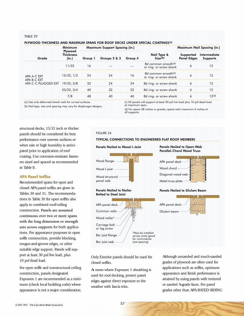
57
Wood flange
Wood structural panel web
APA panel deck
Wood chord
Diagonal wood web
Metal truss plate
Wood I-joist
Panels Nailed to Nailer Bolted to Steel Joist
Panels Nailed to Glulam Beam
APA panel deck
Common nails
Wood nailer*
Bar joist web
APA panel deck
Glulam beam
*May be installed across joists (good for nonmodular joist spacing).
Carriage bolt or lag screw
Bar joist flange
Panels Nailed to Wood I-Joist Panels Nailed to Open-Web Parallel-Chord Wood Truss
FIGURE 24
TYPICAL CONNECTIONS TO ENGINEERED FLAT ROOF MEMBERS
TABLE 29
PLYWOOD THICKNESS AND MAXIMUM SPANS FOR ROOF DECKS UNDER SPECIAL COATINGS(c)
Minimum Maximum Support Spacing (in.) Maximum Nail Spacing (in.)PlywoodThickness Nail Type & Supported Intermediate
Grade (in.) Group 1 Groups 2 & 3 Group 4 Size(b) Panel Edges Supports
11/32 16 — —8d common smooth(a)
6 12or ring- or screw-shank
APA A-C EXT 15/32, 1/2 24 24 168d common smooth(a)
6 12APA B-C EXT
or ring- or screw-shank
APA C-C PLUGGED EXT 19/32, 5/8 32 24 24 8d ring- or screw-shank 6 12
23/32, 3/4 40 32 32 8d ring- or screw-shank 6 12
7/8 48 40 40 8d ring- or screw-shank 6 12(d)
structural decks, 15/32 inch or thickerpanels should be considered for bestperformance over uneven surfaces orwhen rain or high humidity is antici-pated prior to application of roof coating. Use corrosion-resistant fasten-ers sized and spaced as recommendedin Table 8.
APA Panel SoffitsRecommended spans for open andclosed APA panel soffits are given inTables 30 and 31. The recommenda-tions in Table 30 for open soffits alsoapply to combined roof/ceiling construction. Panels are assumedcontinuous over two or more spanswith the long dimension or strengthaxis across supports for both applica-tions. For appearance purposes in opensoffit construction, provide blocking,tongue-and-groove edges, or other suitable edge support. Panels will sup-port at least 30 psf live load, plus 10 psf dead load.
For open soffit and nonstructural ceilingconstruction, panels designatedExposure 1 are recommended as a mini-mum (check local building code) whereappearance is not a major consideration.
Only Exterior panels should be used forclosed soffits.
At eaves where Exposure 1 sheathing isused for roof decking, protect paneledges against direct exposure to theweather with fascia trim.
Although unsanded and touch-sandedgrades of plywood are often used forapplications such as soffits, optimumappearance and finish performance isattained by using panels with texturedor sanded A-grade faces. For panelgrades other than APA RATED SIDING
(a) Use only deformed-shank nails for curved surfaces.
(b) Nail type, size and spacing may vary for diaphragm designs.
(c) All panels will support at least 30 psf live load plus 10 psf dead load at maximum span.
(d) For spans 48 inches or greater, space nails maximum 6 inches at all supports.

58
TABLE 30
APA PANELS FOR OPEN SOFFIT OR FOR COMBINED ROOF DECKING-CEILING(a)(b)
(Strength axis across supports. For APA RATED SHEATHING, where appearance is not a major concern, see Table 24.)Maximum Span Panel Description Species Group
(inches) (All panels Exterior or Exposure 1) for Plywood
15/32" APA RATED SIDING 303 1, 2, 3, 416
15/32" APA MDO, Sanded and Touch-Sanded Plywood 1, 2, 3, 4
15/32" APA RATED SIDING 303 1
15/32" APA MDO, Sanded and Touch-Sanded Plywood 1, 2, 3
24 19/32" APA RATED SIDING 303 1, 2, 3, 4
19/32" APA MDO, Sanded and Touch-Sanded Plywood 1, 2, 3, 4
APA RATED STURD-I-FLOOR 16 oc —
19/32" APA RATED SIDING 303 1
19/32" APA MDO, Sanded and Touch-Sanded Plywood 1
32 23/32" APA Textured Plywood(c) 1, 2, 3, 4
23/32" APA MDO, Sanded and Touch-Sanded Plywood 1, 2, 3, 4
APA RATED STURD-I-FLOOR 20 oc —
48 1-1/8" APA Textured Plywood(c) 1, 2, 3, 4
APA RATED STURD-I-FLOOR 48 oc —
TABLE 31
APA PANELS FOR CLOSED SOFFIT OR FOR NONSTRUCTURAL CEILING(a)(c) (Strength axis across supports)Maximum Span (in.) Nominal Nail SizeAll Edges Supported Panel Thickness Species Group and Type(a)
24 11/32" APA(b)6d nonstaining
32 15/32" APA(b)box or casing
48 19/32" APA(b) 8d nonstainingbox or casing
AllSpeciesGroups
(a) All panels will support at least 30 psf live load plus 10 psf dead load atmaximum span.
(b) For appearance purposes, blocking, tongue-and-groove edges or othersuitable edge supports should be provided.(c) Also see Table 24 for APA RATED SHEATHING/CEILING DECK.
(a) Space nails maximum 6 inches at panel edges and 12 inches at intermediate supports for spans less than 48 inches; 6 inches at all supports for 48-inch spans.
(b) Any suitable grade panel which meets appearance requirements – Exteriorfor closed soffits, Exposure 1 or Exterior for nonstructural ceiling.(c) For appearance purposes, blocking, tongue-and-groove edges or othersuitable edge supports should be provided.
ROOF CONSTRUCTION

59
struction (see page 64), shear values for19/32" panels are used. Blocked shearvalues for 1-1/8" panels may beobtained by specifying stapled T&Gedges. Staples shall be 16 gauge, 1" longwith a 3/8" crown, driven through theT&G edges 3/8" from the joint so as topenetrate the tongue. Staples shall bespaced at one-half of the boundary nailspacing for Cases 1 and 2, and at one-third the boundary nail spacing for Case3 through 6, as illustrated in Table 32.Table 32 gives panel and fasteningrecommendations for roof diaphragms.Panels and framing are assumed alreadydesigned for perpendicular loads. Todesign a diaphragm, follow these steps:
1. Determine lateral loads and resulting shears.
2. Determine nailing schedule(Table 32). Consider load direction with respect to joints.
3. Compute chord stress due to bending moment. Provide adequatesplices. Check deflection. Checkanchorage of boundary framing (e.g., chords) to walls.
For information about developing higher diaphragm shears than shown inTable 32, See Diaphragms and ShearWalls, APA Form L350.
RATED SHEATHING
EXPOSURE 1SIZED FOR SPACING
40/20 19/32 INCH
000PRP-108 HUD-UM-40
THE ENGINEEREDWOOD ASSOCIATION
APA
303, top-quality acrylic latex housepaint systems provide best performance(see page 48). Face-checking (separa-tions between fibers parallel to the grainof the face veneer) can be expected onnon-overlaid plywood which is exposedto the outdoors, even when finished. Ifa smooth, check-free surface is desired,use Medium Density Overlay (MDO) plywood.
APA Panel Roof DiaphragmsWith only slight design modifications,any APA panel roof deck systemdescribed in the previous sections will
Strength axisShim at each rafter for flush joint at change of panel thickness if necessary
Any appropriate APA Exterior or Exposure 1 panel grade and thickness for desired appearance and load-carrying capacity (see Tables 24 and 30)
APA RATED SHEATHING
FIGURE 25
OPEN SOFFIT
Strength axis
Protect edges of Exposure 1 sheathing against exposure to weather
Any appropriate grade of Exterior panels for soffit(see Table 31)
Continuous screened vent or louvered vent
Leave 1/8" space at all panel end and edge joints. Support all panel edges.
FIGURE 26
CLOSED SOFFIT
APA RATED SHEATHING
RATED SHEATHINGSTRUCTURAL I
EXPOSURE 1SIZED FOR SPACING
32/16 15/32 INCH
000PS 1-95 C-D PRP-108
THE ENGINEEREDWOOD ASSOCIATION
APA
RATED SHEATHING
EXPOSURE 1SIZED FOR SPACING
24/16 7/16 INCH
000PS 2-92 SHEATHINGPRP-108 HUD-UM-40
THE ENGINEEREDWOOD ASSOCIATION
APA
RATED SHEATHING
EXPOSURE 1SIZED FOR SPACING
24/0 3/8 INCH
000STRUCTURAL I RATEDDIAPHRAGMS-SHEAR WALLS
PRP-108 HUD-UM-40
THE ENGINEEREDWOOD ASSOCIATION
APA
also function as an engineereddiaphragm to resist high wind andseismic loading. A diaphragm’s ability to function effectively as a beam, trans-ferring lateral loads to shear walls, isrelated to the quality of the connections.Nailing is critical since shears are transmitted through these fasteners.Common nails provide requiredstrength. Other nail types may be usedwhen their lateral bearing values areconsidered in the design. Load-carryingcapacity is highest when the diaphragmis blocked. Where 1-1/8" roof panels aredesired, such as for Heavy Timber con-

60
TABLE 32
RECOMMENDED SHEAR (POUNDS PER FOOT) FOR HORIZONTAL APA PANEL DIAPHRAGMS WITH FRAMING OF DOUGLAS-FIR, LARCH OR SOUTHERN PINE(a) FOR WIND OR SEISMIC LOADING
Blocked Diaphragms Unblocked DiaphragmsNail Spacing (in.) at Nails Spaced 6" max. at
diaphragm boundaries Supported Edges(b)
(all cases), at continuous panel edges parallel to load (Cases 3 & 4),
and at all panel edges (Cases 5 & 6)(b)
Minimum 6 4 2-1/2(c) 2(c) Case 1 (NoMinimum Minimum Nominal unblocked
Nail Nominal Width of Nail Spacing (in.) at edges or All otherPenetration Panel Framing other panel edges continuous configurations
Common in Framing Thickness Member (Cases 1, 2, 3 & 4)(b) joints parallel (Cases 2, 3,Panel Grade Nail Size (inches) (inch) (inches) to load) 4, 5 & 6)
6 6 4 3
6d(e) 1-1/4 5/16 2 185 250 375 420 165 1253 210 280 420 475 185 140
8d 1-3/8 3/8 2 270 360 530 600 240 1803 300 400 600 675 265 200
10(d) 1-1/2 15/32 2 320 425 640 730 285 2153 360 480 720 820 320 240
5/16 2 170 225 335 380 150 1103 190 250 380 430 170 125
6d(e) 1-1/4
3/8 2 185 250 375 420 165 1253 210 280 420 475 185 140
3/8 2 240 320 480 545 215 1603 270 360 540 610 240 180
8d 1-3/8 7/16 2 255 340 505 575 230 1703 285 380 570 645 255 190
15/32 2 270 360 530 600 240 1803 300 400 600 675 265 200
15/32 2 290 385 575 655 255 1903 325 430 650 735 290 215
10d(d) 1-1/2
19/32 2 320 425 640 730 285 2153 360 480 720 820 320 240
APA RATEDSHEATHINGAPA RATEDSTURD-I-FLOOR and other APA gradesexcept SpeciesGroup 5
APASTRUCTURAL Igrades
Case 5Case 2 Case 4Load LoadLoadLoad
Continuous panel jointsContinuous panel joints
Load
Diaphragm boundary
FramingCase 6
Continuous panel joints
Case 3 Blocking,if used
Blocking,if used
Blocking,if used
Case 1Load Framing Framing
(a) For framing of other species: (1) Find specific gravity for species of lumber inthe AFPA National Design Specification. (2) Find shear value from table abovefor nail size for actual grade. (3) Multiply value by the following adjustment fac-tor: Specific Gravity Adjustment Factor = [1 – (0.5 – SG)], where SG = specificgravity of the framing. This adjustment shall not be greater than 1.
(b) Space nails maximum 12 inches o.c. along intermediate framing members (6 in. o.c. when supports are spaced 48 in. o.c. or greater). Fasteners shall belocated 3/8 inch from panel edges.
(c) Framing at adjoining panel edges shall be 3-in. nominal or wider, and nailsshall be staggered where nails are spaced 2 inches o.c. or 2-1/2 inches o.c.
(d) Framing at adjoining panel edges shall be 3-in. nominal or wider, andnails shall be staggered where 10d nails having penetration into framing ofmore than 1-5/8 inches are spaced 3 inches o.c.
(e) 8d is recommended minimum for roofs due to negative pressures of high winds.
Notes: Design for diaphragm stresses depends on direction of continuouspanel joints with reference to load, not on direction of long dimension orstrength axis of sheet. Continuous framing may be in either direction forblocked diaphragms.
ROOF CONSTRUCTION

61
fire-resistive rating for exterior wallsapplies only to the inside of the wallwhen separation to the property line isgreater than 5 feet. In this commonsituation, the gypsum sheathing can beomitted under the siding as noted inFigure 28.
Fire-rated protected wall assemblies willqualify for the one-hour rating if othermaterials are added over the fire-resistivematerials. For example, APA RATEDSIDING panels or lap siding may beattached to the outside of a rated wallwithout impairing the rating.
Roof CoveringsThe fire resistance ratings of roofingmaterials are listed as Class A, B, or C in descending order of fire protectionafforded. Their use is prescribed bybuilding codes, and also affects insur-ance rates. Untreated APA RATEDSHEATHING panels are recognized as a structural roof deck substrate for rated roof coverings. For individualrequirements, see the U.L. RoofingMaterials and Systems Directory.
Wall and Ceiling PanelingThe Flame Spread Classification ofmaterials used for interior wall andceiling finish (and occasionally for otherapplications) is usually limited by building codes for certain occupancies.Tests have shown that untreated APAwood structural panels will developflame spread index and smoke indexvalues of 200 or less, which puts themin a Class III (or C) category.
Panels are therefore suitable as interiorfinish for most applications. Certainmore restrictive locations, such as exitways, require a Class I or Class IIrating which can be achieved by the use of fire-retardant-treated plywood.(See page 15.)
Fire-resistant Construction Protected ConstructionProtected construction includes typical floor-ceiling, roof-ceiling or wallassemblies with wood structural panelsfastened to wood or steel framing, and afire-resistive material such as gypsumwallboard, plaster or mineral acousticaltile added to give primary protection toframing. The structural panels slowflame passage and temperature risewhile reinforcing supports against collapse under load.
Assemblies are rated in fire tests byUnderwriters Laboratories (U.L.) andother agencies. Over 40 floor-ceiling(and/or roof-ceiling) systems usingwood structural panels are described inthe U.L. Fire Resistance Directory. Theyare accepted as rated constructions bymost building codes. Two examples ofone-hour-rated floor-ceiling assembliesare shown in Figure 27; several two-hour-rated wood framed assemblies alsoare described in the U.L. Directory.
Building Requirements In many fire-resistant floor-ceilingassemblies, a two-layer floor system(15/32-inch subfloor and 19/32-inchunderlayment) is used, although severalhave single-layer 5/8-inch or thickercombination subfloor-underlaymentpanels. Any finish floor material may beused. Most codes permit omission ofthe top panel layer in roof assemblies.
Plywood siding or wall sheathing incombination with gypsum sheathingand wallboard on studs is recognized bycode officials for one-hour load-bearingexterior walls. A typical example – APA RATED SIDING over 5/8-inch TypeX gypsum sheathing attached to 2xstuds 16 or 24 inches on center – isillustrated in Figure 28, page 63. Undertwo of the model building codes, the
BUILDING
REQUIREMENTS
AND RELATED
PANEL SYSTEMS

62
Structural Glued Laminated Timber (Glulam)A structural member’s fire resistance ismeasured by the time it can support itsdesign load during a fire. An exposedbeam or column sized for a minimumone-hour fire resistance will support itsfull design load for at least one hourduring standard fire test conditionswhich simulate an actual fire.
Beams. Glulam beams 6-3/4" and8-3/4" wide can be adapted to a one-hour fire rating in accordance withprocedures recognized by the modelcodes. For these widths, there is aminimum depth for a one-hour firerating. The minimum depth increaseswhen the design calls for the beam to beexposed on four rather than three sides.See Table 33.
To adapt beams whose dimensionsqualify them for one-hour fire rating, thebasic layup is modified as shown inFigure 29. One core lamination fromthe center of the beam is required by anadditional tension lamination.
Columns. Column length determinesthe minimum size for one-hour ratings.The column size needed for a one-hourfire rating is determined by calculatingthe l/d and then using the appropriateminimum dimensions; see Table 34.
Columns generally need no speciallayup to qualify for a one-hour fire rating. For both 8-3/4" and 10-3/4"widths, all columns meeting the mini-mum size standard satisfy the one-hourfire rating requirement.
As with all structural framing, finalspecifications of members designed tohave one-hour fire resistance should be carefully checked by a professionalengineer or architect to assure compli-ance with all local building codes.
19/32" T&GAPA plywood
underlayment(b)(c) (Most codes do not
require the top layer of two-layer rated assemblies when used for roofs.)
23/32" T&G APA plywood(b)(c)
Constructionadhesive at trusses
and T&G edges
Building paper
15/32" APA plywood subfloor(b)
Joists 16" o.c. (2x10s min.)
5/8" Type X or proprietary* Type X gypsum wallboard ceiling; resilient channels required in some assemblies
Wood I-joists or trusses 24" o.c.
*For proprietary names see latest U.L. Fire Resistance Directory
1/2" proprietary* Type X gypsum wallboard ceiling
(2 layers)
Resilient channels spaced 16" o.c.
FIGURE 27
ONE-HOUR FIRE-RATED COMBUSTIBLE FLOOR/CEILING(OR ROOF/CEILING) ASSEMBLIESSome rated assemblies incorporate proprietary products. When designing and specifying, check the Underwriters Laboratories Fire Resistance Directory for complete details on a particular assembly. A change in details may affect fire resistance of the assembly.
1. Two-layer floor systems with joists.(a) For details, see U.L. Design Nos. L001, L003, L004, L005, L006, L201, L202, L206, L208 (1-1/2 hr), L209, L210, L211 (2 hr), L212, L501, L502, L503, L505 (2 hr), L511 (2 hr), L512, L514, L515, L516, L519, L522, L523, L525, L526, L533, L535, L536 (2 hr), L537, L541 (2 hr) and L545. Also see U.L. Designs No. L524 and L527 (1-1/2 hr single layer) with steel joists spaced 24" o.c., and L521 with wood trusses spaced 24" o.c.
2. Single-layer floor systems with wood I-joists or trusses. For details, see U.L. Design Nos. L528, L529, L534, L542 and L544 (shown). Also see U.L. Design No. L513 for single-layer floor system with lumber joists spaced 24" o.c.
Note:(a) Substitution of 1-1/8" APA RATED STURD-I-FLOOR 48 oc for the combination of subfloor, paper, and underlayment is often allowed. Check with local Building Official.(b) Tests have shown that substitution of OSB or composite APA RATED SHEATHING subfloor and APA RATED STURD-I-FLOOR underlayment for the plywood panels in rated assemblies will not jeopardize fire-resistance ratings. Substitution is based on equivalent panel thickness, except that 7/16" OSB subfloor panels may be used in place of 15/32" plywood subfloor panels in two-layer assemblies. OSB panels are listed as alternates to plywood subflooring or finish flooring in U.L. Design Nos. L501, L503, L505 (2hr), L508, L511 (2hr), L513, L514, L516, L521, L526, L528, L529, L532 (1-1/2 hr), L539, L540, L543, L544, L546, L548, L550, L551 and L552.(c) Lightweight concrete or gypsum concrete floor topping permitted over single-layer floor or as alternate to plywood underlayment in many assemblies (check details).
BUILDING REQUIREMENTS AND RELATED PANEL SYSTEMS

63
Metal Connectors. In structures usingone-hour rated glulams, supportingmetal connectors and fasteners also mustbe designed to achieve a one-hour firerating. A 1-1/2" covering of wood, 5/8"fire-rated (Type X) gypsum wallboard orany coating approved for a one-hourrating provides the needed protection.
For further information, see EWSTechnical Note EWS Y245, CalculatingFire Resistance of Glulam Beams andColumns.
TABLE 33
ONE-HOUR FIRE-RATED GLULAMBEAMS – MINIMUM DEPTHS FOR6-3/4" AND 8-3/4" WIDE BEAMS
Minimum Depth (inches)
Beam Width 3 Sides 4 Sides(inches) Exposed Exposed
6-3/4 13-1/2 27
8-3/4 7-1/2 13-1/2
TABLE 34
ONE-HOUR FIRE-RATED GLULAM COLUMNS – MINIMUMDEPTHS FOR 8-3/4" AND 10-3/4"COLUMN WIDTHS
Minimum Depth (inches)
Columnl/d Width 3 Sides 4 SidesCriteria (in.) Exposed Exposed
l/d>11 8-3/4 15 3010-3/4 10-1/2 13-1/2
l/d≤ 11 8-3/4 9 1210-3/4 7-1/2 10-1/2
l = column length in inches.d = column least cross-sectional
dimension in inches.
2x4 studs all 16" or 24" o.c.
5/8" Type X gypsum wallboard
5/8" Type X gypsum sheathing(b)
APA RATED SIDING 16 or 24 oc (or panel sheathing)
Mineral or glass fiberinsulation (optional)
FIGURE 28
ONE-HOUR FIRE-RATED EXTERIOR LOAD-BEARING WALL ASSEMBLY(a)
(a) Generic, non-proprietary assembly based on GA File No. WP8105 listed in Gypsum Association Fire Resistance Design Manual, referenced in the model building codes. Mineral or glass fiber batt insulation (optional).
(b) Exterior layer of gypsum sheathing not required under the National and Standard Building Codes, or the International Building Code, when separation is greater than 5 feet. Check local provisions. See U.L. Design U356 in U.L. Fire Resistance Directory.
Core lam from center replaced by tension lam added at bottom
Tension lams at bottom
Core lams in center
Compression lams at top
FIGURE 29
ONE-HOUR FIRE-RATED GLULAM BEAM(Layup for simple span)

64
TABLE 35
DIMENSIONS OF COMPONENTSFOR HEAVY TIMBER CONSTRUC-TION (TYPICAL CODE PROVISIONS)
Heavy Timber construction is gener-ally defined in building codes andstandards by the following minimumsizes for the various members or portions of a building:
Inches, nominalColumns–supporting floor loads ..............................8 x 8Supporting roof and ceiling loads only ................................6 x 8
Floor framingBeams and girders ...................6 wide x 10 deepArches and trusses ................8 in any dimension
Roof framing –not supporting floor loadsArches springing from grade .......................6 x 8 lower half
6 x 6 upper half
Arches, trusses, other framing springing from top of walls, etc. .......................4 x 6
Floor (covered with 1-inch nominal flooring, 15/32- or 1/2-inch wood structural panels, or other approved surfacing) Splined or tongue-and-groove plank ................................. 3Planks set on edge .........................4
Roof decksSplined or tongue-and-groove plank .................................2Plank set on edge ..........................3Tongue-and-groove wood structural panels ............1-1/8
structural panels APA RATED SHEATH-ING/CEILING DECK panels can bespecified.
Heavy timber floors may also be con-structed with 15/32-inch wood struc-tural panels over three-inch planks.
For additional information on fire-resistant construction, see APADesign/ Construction Guide: Fire-RatedSystems, Form W305.
Wind-resistive RoofsWind ratings are based on a roof system’s performance in wind uplifttests. Systems meeting U.L. require-ments are assigned a semi-wind-resistiveclassification (Class 30 or 60) or fully-wind-resistive classification (Class 90).
Many of the fire-rated assemblies alsocan qualify for these ratings. HeavyTimber usually is accorded semi-wind-resistive recognition.
There are over 70 U.L. listed roofing/roof deck systems with plywood sheath-ing for fully-wind-resistive Class 90ratings. One of the systems, NM519, isillustrated in Figure 31. Another isNM520, a panelized roof deck of15/32-inch APA RATED SHEATHING32/16 Exposure 1 plywood marked PS 1(CDX, 4 plies minimum, all-Group 1
Heavy Timber Construction Model building codes also recognizeHeavy Timber wood constructionsystems, which can simplify roof or floorconstruction while providing superiorfire resistance. Heavy Timberconstruction does not constitute one-hour fire resistance, however.
Under fire conditions, large size timbermembers develop a surface char layerwhich acts as insulation to slow theburning process. In addition, HeavyTimber construction does not permitconcealed wall or ceiling spaces wherefire can spread. Years of fire serviceexperience shows that the structuralperformance of Heavy Timber construc-tion systems under fire conditions ismarkedly superior to most unprotected“noncombustible” (steel) structures.
See Table 35 for minimum structuralmember sizes required by model build-ing codes for Heavy Timber construc-tion. Structural glued laminated timber(glulams) also qualifies for HeavyTimber construction systems whenmembers conform to required sizes.
Insurance rating bureaus and all of themodel building codes accept 1-1/8-inchtongue-and-groove wood structuralpanels with exterior glue (Exposure 1)as an alternative to two-inch nominaltongue-and-groove lumber decking inheavy timber roof construction.
Typical construction (Figure 30) consists of tongue-and-groove APARATED STURD-I-FLOOR 48 ocExposure 1 (or 1-1/8-inch tongue-and-groove APA RATED SHEATHINGExposure 1 – Check local availabilitybefore specifying). Heavy timber beamsmust be 4x6 minimum and are nor-mally spaced 48 inches on center. Foran exposed ceiling with improvedappearance, 1-1/8-inch textured wood
Built-up roofing
Strength axis
Structural glued laminated timber (glulam) or solid timber beams (4x6 minimum)
FIGURE 30
HEAVY TIMBER ROOF CONSTRUCTION
1-1/8" APA T&G wood structural panels with exterior glue (Exposure 1) –
APA RATED STURD-I-FLOOR 48 oc typical
BUILDING REQUIREMENTS AND RELATED PANEL SYSTEMS

65
species) on 2-inch nominal stiffenersspanning eight feet between purlinsframed into glulam beams. See Figure 32for further information. This panelizedroof is commonly used for seismic orwind resistance, utilizing the diaphragmshear strength of the plywood.
Other fully-wind-resistive Class 90 roofsystems with proprietary metal roofingpanels, using plywood or OSB panelsas a roofing substrate over steel decking,or as structural roof sheathing, also meetU.L. requirements. See Figure 33.
For additional information, see APADesign/Construction Guide: NonresidentialRoof Systems, Form A310 and U.L. RoofMaterials and Systems Directory.
Noise Transmission ControlWhile some attention to sound controlmay be desirable in certain types ofsingle-family residential buildings, it ismandatory in multifamily, commercialand industrial construction.
Selection of the correct noise-resistantsurface and insulation assemblies isbased on Sound TransmissionClass (STC) and Impact Insulation Class (IIC). The STC rates a structuralassembly’s ability to reduce airbornenoise. Most authorities agree that amulti-occupancy residential floor or wallshould have an STC rating of at least 45,while over 50 is considered premiumconstruction. Below 40, loud speechcan be audible as a murmur and privacyand comfort are impaired. The level ofbackground noise affects the choice of STC.
The IIC ratings define the capacity tocontrol impact noise and have replacedthe earlier Impact Noise Rating (INR).In most cases, required IIC rating valuesare about the same as for STC.
• •
•
•
•
•
•
•
•
•
•
•
•
•
•
• •
• • • •
• •
Base sheet (U.L. TypeG2 asphalt glass fiber mat, 20 lb nominal)(b)
Plywood face grain direction
15/32" APA RATED SHEATHING 32/16 Exposure 1 plywood marked PS 1
8d common deformed shank nails, spaced 6" o.c. at panel ends and 12" o.c. at interior supports
(a) Design in accordance with local building code requirements for roof loads and anchorage. All framing must have 2" nominal or greater width for plywood deck nailing.(b) Install roofing base and ply sheets with roll direction parallel to plywood face grain directions.
Two-ply sheets (U.L. Type G1 asphalt glass fiber mat, 10 lb nominal) hot-mopped with surface flood coat(b)
2" nominal Douglas-fir or southern pine fram-
ing spaced 24" o.c. maximum(a)
1/4"-wide rayontape (rows spacedat 8-1/2" o.c. typ.)
16-ga. x 7/8"-long coated staples spaced 4" o.c. typ.
FIGURE 31
FULLY-WIND-RESISTIVE ROOF ASSEMBLY — U.L. CLASS 90 (NM519)
• •
•
•
•
•
•
•
•
•
•
•
•
•
• •
•
•
•
•
•
•
•
•
• •
•
•
• •
•
•
•
•
•
•
•
•
•
•
•
1/4"-wide rayon tape (rows spaced at 8-1/2" o.c.,(b) with 16-ga. x 7/8"-long
coated staples spaced 4" o.c.)
2" nominalDouglas-fir or
southern pine fram-ing spaced 24" o.c.
15/32" APA RATED SHEATHING 32/16 Exposure 1 plywood marked PS 1 (4 plies minimum, all Group 1
species) or 15/32" APA STRUC-TURAL I RATED SHEATHING 32/16
plywood marked PS 1
(a) Trusses or I-joists used for purlins must have chords or flanges of 1-3/4" minimum depth for plywood deck nailing.(b) For semi-wind-resistive assemblies (Class 60), plywood deck nailing spaced 6" o.c. at all supports and roofing base sheet attached with rayon tape rows spaced 11-1/3" o.c(c) Install roofing base and ply sheets with roll direction parallel to plywood face grain direction.
10d (short or diaphragm) common nails, 4" o.c. at edges and 6" o.c. at interior supports(b)
Steel joist hangers
Plywood face grain direction
Base sheet (U.L. Type G2 asphalt glass fiber mat, 20 lb nominal)(c)
Two-ply sheets (U.L. Type G1 asphalt glass fiber mat, 10 lb nominal) hot-mopped with surface flood coat(c)
Roof purlins or trusses spaced 8' o.c.(a)
FIGURE 32
FULLY-WIND-RESISTIVE ROOF ASSEMBLY — U.L. CLASS 90 (NM520)

66
Figures 34 and 35 show only two of the many sound-resistant floor and wall assemblies that can be obtainedwith wood structural panels. Some floor-ceiling assemblies also qualify asfire-rated construction.
While many listed assemblies weretested using plywood, other APA OSBand composite structural-use panelsmay be substituted on a thickness forthickness basis. Because of their similarstrength and stiffness properties andslightly higher density, use of theseproducts in lieu of plywood will notcompromise the STC or IIC ratings ofthe tested systems.
For additional information, see APADesign/Construction Guide: Noise-RatedSystems, Form W460.
• •
•
•
•
•
•
•
•
• •
•
•
•
•
•
•
•
•
• •
•
•
•
•
•
•
•
•
APA RATED SHEATHING plywood per PS 1 (min. 15/32" for framing spaced 16" o.c.; 19/32", 5/8 or 3/4" for fram-ing spaced 24" o.c.)
Caulk or tape to seal joints (check manufacturers’ recommendations)
8d deformed shank nails or No. 8 x 2" screws @ 6" o.c. at edges and 6" or 12" o.c. at interior supports (for steelframing, No. 6 x 1-1/4" or No. 12 x 1-5/8" screws)
(a) Some rated assemblies and constructions incorporate OSB sheathing and proprietary products. When designing and specifying, check the Underwriters Laboratories (U.L.) Roofing Materials and Systems Directory (Category TGKX) for complete details on a particular assembly in U.L. Construction Nos. 200-500 (series). A change in details may affect the wind uplift classification of the assembly.
2x4 wood framing (joists bolted to steel purlinsspaced 48 - 60" o.c., or top chord of trusses), 2x6 wood framing, or steel framing (min. 22 gage)
No. 15 asphalt felt vaporretarder – one or two layers
(may be optional)
Metal roofing panels fastened to plywoodor framing with steel clips and screws
24" max.
FIGURE 33
METAL ROOFING PANELS — U.L. CLASS 90(a)
1-1/2" lightweight concrete on No.15 asphalt felt
Carpet and pad
5/8" APA RATED SHEATHING subfloor
Wood joists 16" o.c.
5/8" gypsum wallboard screwed to resilient channels; joints taped
(a) Also meets minimum construction requirements for one-hour fire-rated floor-ceiling assembly per Underwriters Laboratory (U.L.) Design No. L514. Ref. Geiger andHamme, Inc. tests CCA-10MT and CCA-11MT (1972).
Resilient channels spaced 24" o.c.
FIGURE 35
NOISE-RESISTANT FLOOR ASSEMBLY(a)
(Lightweight Concrete Over APA Panels) STC = 58; IIC = 73
3/8" APA RATED SHEATHING applied vertically with 6d common nails spaced 6" o.c. at edges, 12" o.c. other framing. Nail heads dimpled into panel.
1/2" gypsum wallboard applied vertically, joints staggered. Nail to framing with 8d nails spaced 12" o.c. Joists taped.
2x4 studs spaced 24” 24" o.c. staggered
2x6 plate top and bottom
FIGURE 34
NOISE-RESISTANT PARTY WALLSTC = 46
BUILDING REQUIREMENTS AND RELATED PANEL SYSTEMS

67
Energy ConservationInsulating Exterior Walls With adoption of more stringent regula-tions concerning building insulation, itis increasingly important to build wallsto meet new requirements as efficientlyas possible. Installation of APA RATEDSIDING panels yields tight constructionto minimize heat loss due to air infiltra-tion. Framed walls also can be easilyinsulated to provide U values found inenergy standards. Figure 36 illustratestwo construction options and theircorresponding U values. One of theassemblies uses APA RATED SIDINGdirect to studs, and one shows sidingapplied over rigid foam insulation.Figure 36 shows the installation of thevapor retarder on the inside of the wallframing for typical construction. Localclimatic conditions, energy codes orstandard construction practices mayvary the actual presence or location ofthe vapor retarder.
Insulating Panel RoofsInsulating APA panel roof decks is sim-pler, quicker and less expensive thanother decks since batt insulation can beapplied on the underside of the deckwhen ventilation is provided – androofing on top – without further prepa-ration. Most metal roof systems, on theother hand, require special rigid insula-tion on top of the deck to provide thesmooth surface needed for roofing. Thepanel deck with blanket insulation alsoprovides better sound absorption, animportant consideration in commercial,industrial and institutional construction.
1/2" gypsum wallboard
Vapor retarder
Batt insulation
Wood studs (2x4 with R11 or R15HD insula-tion or 2x6 with R19 or R21HD insulation)
APA RATED SIDING (11/32" or thicker)
APA RATED SIDING OVER RIGID FOAM INSULATION SHEATHING
APA RATED SIDING DIRECT TO STUDS
R
Outside surface (15 mph wind) 0.17APA RATED SIDING 0.43–0.78Batt insulation Option A – R11 11.00 Option B – R15HD (high density) 15.00 Option C – R19 18.00(a) Option D – R21HD (high density) 21.001/2" gypsum wallboard 0.45Inside surface (still air) 0.68
Insulation MinimumOption Average U Effective R = 1/U
A 0.100 10.01B 0.086 11.66C 0.065 15.36D 0.060 16.70
1/2" gypsum wallboard
Vapor retarder
Batt insulation
Wood studs (2x4 with R11 or R15HD insula-tion or 2x6 with R19 or R21HD insulation)
APA RATED SIDING (11/32" or thicker)
Rigid foam insulation (R4 min.)
FIGURE 36
ENERGY-CONSERVING STURD-I-WALL ASSEMBLIES
Insulation MinimumOption Average U Effective R = 1/U
E 0.070 14.37F 0.061 16.42G 0.050 19.87H 0.047 21.44
R
Outside surface (15 mph wind) 0.17APA RATED SIDING 0.43–0.78Rigid foam insulation 4.00 (min.)Batt insulation Option A – R11 11.00 Option B – R15HD (high density) 15.00 Option C – R19 18.00(a) Option D – R21HD (high density) 21.001/2" gypsum wallboard 0.45Inside surface (still air) 0.68
(a) When compressed to 5-1/2" thickness.
(b) Average U values include adjustment for 25% framing area with studs spaced 16" o.c. When studs are spaced 24" o.c. (22% framing area), average U values are slightly lower and corresponding R values are higher. Average U value is based on R value at framing of 4.38 for 2x4 wood studs and 6.88 for 2x6 wood studs.

68
No Insulation Roofing Reflective Insulation(a)
Outside surface
Inside surface Ventilated air space Air space
No. of equal air spaces1 23
Winter 0.2540.183
0.117
Summer0.1000.0750.066
(a) Foil sheets assumed reflective both sides except exposed bottom.
Batt Insulation
APA panel roof deck Winter
0.578Summer0.472
Rigid Insulation
Rigid insulation board
Ventilated air space
Fiberboard/perlite board
Composite board
Polyurethane board
1 in.1-1/2 in.2 in.
1-1/2 in.2 in.
1 in.1-1/2 in.
Winter0.2220.1690.143
0.1190.085
0.0990.070
Summer 0.204 0.159 0.136
0.114 0.083
0.096 0.068
(b) Min. 2x6 joists required to provide air space.
R11(b) Winter0.082
Summer0.079
FIGURE 37
AVERAGE "U" VALUES OF APA PANEL ROOF DECKS
A wood frame-panel roof deck systemcan be effectively insulated through avariety of techniques. Figure 37 showsfour APA panel roof decks – three withinsulation and one without. Average Uvalues for below-deck insulation includeadjustment for 8 percent framing area.
Condensation:Its Cause and ControlToday’s construction techniques usuallyproduce a far better sealed and insulatedbuilding than those built in the past. Atthe same time, the modern house islikely to be equipped with appliancesthat give off moisture. It is more important than ever before, therefore, to provide adequate measures for controlling moisture and condensation.Lack of attention to this area may causedifficulties and costly callbacks.
Studies show that moisture originatesboth inside and outside the structure.Trouble may start with condensation onthe underside of roof decking in theattic. Moisture transmission throughwalls can cause paint failures on exteriorwalls. The solution is adequate ventila-tion and properly placed moisture vaporretarders. The latter should always belocated on or near the warm side ofwalls and floors. Ceiling vapor retardersare typically omitted where attics arewell ventilated.
Minimum ventilation requirements forboth attic and crawl space appear in theCABO One and Two Family DwellingCode, the International ResidentialCode, and in other model buildingcodes. The requirements are based onthe ratio of the free ventilation area tothe area to be ventilated. The requiredratio is 1 to 150, applicable to bothcrawl spaces and attic areas. When aground cover is placed in the crawl
space, the crawl space ventilation ratiomay be reduced to 1 to 1500. The ratioin the attic area may be reduced to 1 to300 provided: 1) a vapor retarder havinga transmission rate not exceeding 1perm is installed on the warm side ofthe ceiling, or 2) at least 50 percent ofthe required ventilating area is providedby ventilators located in the upper por-tion of the space to be ventilated, withthe balance of the required ventilationprovided by eave or cornice vents.
In general, condensation can be con-trolled with a vapor retarder placed onthe warm side of the walls and belowconcrete slabs or as a ground cover incrawl spaces, along with adequate venti-lation in attics and crawl spaces.
Ventilation should not be cut off at anytime during the year when it is the onlymeans of moisture control in crawl
spaces. In cold climates, low temper-atures beneath the first floor may beexpected in a ventilated crawl space,and insulation will be required in thefloor and around exposed mechanicallines. When a vapor retarder is installedfor ground cover, vents may be closableand the perimeter foundation wall maybe insulated in lieu of the floor.
Moisture control recommendations forlow slope APA panel roof decks aredescribed in Engineered Wood Systems(EWS) Technical Note, Moisture Controlin Low Slope Roofs, Form EWS R525,available from APA.
Additional information is available inEngineered Wood Systems (EWS)Technical Note, Controlling Decay inWood Construction, Form EWS R495.
BUILDING REQUIREMENTS AND RELATED PANEL SYSTEMS

69
use hot-dipped or hot-tumbled galva-nized nails. If the underside of the joistsis covered, the floor-ceiling cavityshould be vented to aid in drying and to prevent potential moisture buildup in the deck.
If there is a dry living area underneaththe deck, apply a membrane roof covering or high performance coatingover the surface. The coating should be able to accommodate normal dimen-sional changes in the plywood withoutrupturing or cracking. Under these conditions, APA RATED STURD-I-FLOOR Exposure 1 may be used unlessotherwise recommended by the coating manufacturer, and preservative treat-ment of the panels is not necessary.
Plywood for Concrete FormingPlywood is an ideal material for concreteforming. It produces smooth concretesurfaces and can be used repeatedly –some overlaid panels up to 200 times ormore. The thinner panels can be benteasily for curved forms and liners.Plywood’s excellent stiffness minimizesdeflection during pouring. Its naturalinsulating qualities help provide moreconsistent curing conditions. The largepanel size and light weight reduce formconstruction and stripping time. Andvarious surface textures are available for imparting attractive and unusualconcrete textures.
Although nearly any Exterior plywoodcan be used for concrete forming, aspecial panel called PLYFORM® Class Iis manufactured specifically for thepurpose. PLYFORM also can be manu-factured with a High Density Overlay(HDO) surface, and in Structural I panels. HDO PLYFORM has an exceptionally hard surface for thesmoothest possible concrete finishesand maximum number of pours.
RELATED
PANEL SYSTEMS
The Permanent Wood FoundationThe Permanent Wood Foundation(PWF), also referred to as the All-Weather Wood Foundation (AWWF), ismade up of pressure-preservative-treatedbelow-grade stud walls built of lumberand APA trademarked plywood. Thesystem is accepted for FHA mortgageinsurance programs. It’s accepted by themajor model building codes and moststate and local codes. And, whether fullbasement or crawl space, the PWF isadaptable to almost any site and light-frame building design.
For complete design and constructionrecommendations, contact the AmericanForest & Paper Association, 1111 19thStreet, NW, Suite 800, Washington, DC20036; or the Southern Pine MarketingCouncil, P.O. Box 641700, Kenner,Louisiana, 70064.
Plywood for Outdoor DecksExterior-type plywood may be used in outdoor deck applications. Recom-mended grades include APA RATEDSTURD-I-FLOOR Exterior, C-CPlugged, Underlayment C-C Plugged, or Marine. Where the deck may beexposed to long-term dampness, suchas applications where the plywood istopped with outdoor carpet, the ply-wood should be pressure-treated with awaterborne ACA or CCA preservative inaccordance with AWPA Standard C9 forabove-ground exposure. For optimumperformance, slope the deck away fromthe structure. A slope of 1/4 to 1/2 inchis suggested.
Space panels 1/8 inch at ends and edgesto allow for expansion. Caulk the jointsto prevent water leakage into areasunderneath. To avoid fastener corrosion,
TABLE 36
THERMAL RESISTANCE
Panel ThermalThickness (in.) Resistance, R(a)
1/4 0.31
5/16 0.39
3/8 0.47
7/16 0.55
15/32 0.59
1/2 0.62
19/32 0.74
5/8 0.78
23/32 0.90
3/4 0.94
7/8 1.09
1 1.25
1-1/8 1.41
(a) Degree F-hr.-sq.ft./BTU
Thermal Resistance of Wood Structural PanelsFor most wood structural panel applications, the most important thermalquality is resistance, or insulating effec-tiveness. While wood structural panelsinclude plywood, OSB and COM-PLYand can be made up of a number ofdifferent species, the thermal resistanceproperty is relatively insensitive to suchdifferences. For determining the overallcoefficient of heat transmission (U), asillustrated above, APA publications relyon the thermal resistance values forsoftwood published by the AmericanSociety of Heating, Refrigeration and AirConditioning Engineers (ASHRAE). Useof this single value simplifies computa-tions and produces only insignificantdifferences in resulting design heatlosses. Table 36 shows thermal resis-tance, R, for several panel thicknesses.

70
Panels Nailed to Nailable Steel Joists
Nailer Anchored with Power Driven Fasteners
Panels Attached Directly to Formed Steel Joist
Hardened screwshank nails required
APA panel deck
Nailable steel joistNailable steel joist
APA panel deck
APA panel deck
APA panel deck
2x4 nailer
Nail to joist
2x4 nailer
Drive pins (size and spacing as
required)
Steel wideflange beam
Adhesive (optional)
Hardened screw-shank nail or self-
tapping fastener
Metal joist (“C” or box
section)
FIGURE 38
TYPICAL PANEL-TO-METAL FRAMING SYSTEMS
Structural I PLYFORM is stronger andstiffer than PLYFORM Class I, particu-larly in the cross-panel direction, and issometimes used for high pressureswhere long dimension is parallel tosupports. Additional plywood gradesdesigned for concrete forming includespecial overlays and proprietary panels.
For complete design information, writefor APA’s Design/Construction Guide:Concrete Forming, Form V345.
Structural Insulated PanelsThe structural insulated panel, or sand-wich panel, offers the stiffness and loadhandling capability of a stressed-skinpanel, plus light weight, high insulationvalues for relatively small thicknesses,and fast panelized construction. Panelsare prefabricated by sandwiching aninsulating core material such as poly-styrene or polyurethane foam, or apaper honeycomb, between wood struc-tural panel “skins.” A structural bond isformed between the core and the skinswith full structural glues or, in the caseof some foam materials, by direct adhesion of foam to the skins.
With APA panel siding for the outsideskin, structural insulated panels makeattractive, energy-conserving walls onboth residential and commercial build-ings. A typical structural insulated floorpanel might have 19/32-inch top skinand 3/8-inch bottom skin. Check localbuilding requirements relating to ther-mal barrier protection of plastic foam.For additional information, write forDesign and Fabrication of PlywoodSandwich Panels, Form U814.
APA Panels Over Metal FramingModern fastening methods are rapidlyexpanding the use of APA panels overmetal framing. Self-drilling, self-tappingfasteners commonly are used to attachpanels up to 1-1/8 inch thick to steelflanges. Panels also can be fastened tolighter members, such as formed steeljoists, with special hardened screw-shank nails. Construction adhesives arerecommended with hardened screw-shank nails. Consult metal framingmanufacturers for recommended
adhesives. Since threads usually extend only part way up the shank ofself-drilling, self-tapping screws andscrew-shank nails, it is important tospecify a length sufficient to engage themetal framing.
Typical panel-to-metal framing systemsare illustrated in Figure 38. Load-spanrecommendations are the same as for wood-frame systems. For more information, write for APA Design/Construction Guide: Wood StructuralPanels Over Metal Framing, Form T625.
BUILDING REQUIREMENTS AND RELATED PANEL SYSTEMS

ROOF
CONSTRUCTION
71
APA Panel Systems Over Concrete SlabsA system of APA panels over sleepers embedded in mastic hasbeen successfully installed overconcrete slabs. Tongue-and-groovepanels eliminate blocking betweensleepers at panel edges and allowair circulation beneath the floor.Use only panels marked Exterior or Exposure 1. A vapor barrier isessential directly above or belowthe slab. Preservative treatment ofthe sleepers is recommended whenthe slab is on or below grade,although panels normally will notrequire treatment.
Tongue-and-groove plywood can beinstalled over polystyrene orpolyurethane foam. The foam,bonded to both the plywood andconcrete slab with mastic, provideshigh insulating value and resistanceto termites, rot and fungus.Exterior plywood at least 15/32inch thick is recommended. Avapor barrier such as polyethyleneis required either directly above orbelow the concrete slab.
Special Floor SurfacingHardboard overlaid plywood (APA PLYRON®) is sometimes used as afinish floor, especially for industrialinstallation. (Check your localdealer for availability.) High DensityOverlay (HDO) panels with a spe-cial heavy-duty screen-grid surfaceprovide skid-resistant, long-wearingsurfaces under foot traffic. And anumber of liquid coatings – somesuitable for balconies, porches,patio decks and other exteriorapplications – are also available.
Always insist on panels bearing the mark of quality – the APA trademark. Your APApanel purchase is not only your highestpossible assurance of product quality, but aninvestment in the many trade services thatAPA provides on your behalf.
The APA EWS trademark appears only onengineered wood products manufactured bymembers of Engineered Wood Systems, arelated corporation of APA. The marksignifies that the manufacturer is committedto a rigorous program of quality verificationand testing and that products are manufac-tured in conformance with an APA ornational standard such as ANSI StandardA190.1, American National Standard forStructural Glued Laminated Timber.
For additional information on woodconstruction systems, contact APA – TheEngineered Wood Association, P.O. Box11700, Tacoma, Washington 98411-0700,or the nearest APA regional field office listed on the back cover. Visit us on theWorld Wide Web at www.apawood.org. Fora list of additional APA and EngineeredWood Systems publications, request the: APA Publications Index, Form B300EWS Publications Index, Form S400
ADDITIONAL
INFORMATION
About APA – The Engineered Wood Association and EngineeredWood SystemsAPA – The Engineered Wood Association isa nonprofit trade association whose membermills produce approximately 75 percent ofthe structural wood panel products manu-factured in North America.
The Association’s trademark appears onlyon products manufactured by member millsand is the manufacturer’s assurance thatthe product conforms to the standard shownon the trademark. That standard may be anAPA performance standard, the VoluntaryProduct Standard PS 1-95 for Constructionand Industrial Plywood or VoluntaryProduct Standard PS 2-92, PerformanceStandards for Wood-Based Structural-UsePanels. Panel quality of all APAtrademarked products is subject to verification through APA audit.
APA’s services go far beyond quality testingand inspection. Research and promotionprograms play important roles in developingand improving plywood and other panelconstruction systems, and in helping usersand specifiers to better understand andapply panel products.

ENGINEERED WOODCONSTRUCTION GUIDE
We have field representatives in most major U.S. cities and in Canada who can helpanswer questions involving APA trademarked
products. For additional assistance in specifyingAPA engineered wood products, contact us:
APA – THE ENGINEERED WOOD ASSOCIATION
HEADQUARTERS 7011 So. 19th St. ■ P.O. Box 11700Tacoma, Washington 98411-0700
(253) 565-6600 ■ Fax: (253) 565-7265
PRODUCT SUPPORT HELP DESK(253) 620-7400
E-mail Address: [email protected]
(Offices: Bournemouth, United Kingdom;Hamburg, Germany; Mexico City, Mexico;
Tokyo, Japan.)
The product use recommendations in this publica-tion are based on APA – The Engineered WoodAssociation’s continuing programs of laboratorytesting, product research, and comprehensive fieldexperience. However, because the Association hasno control over quality of workmanship or the con-ditions under which engineered wood products areused, it cannot accept responsibility for productperformance or designs as actually constructed.Because engineered wood product performancerequirements vary geographically, consult yourlocal architect, engineer or design professional toassure compliance with code, construction, andperformance requirements.
Form No. E30R/Revised January 2001/0800
www.apawood.org@Web Address:
THE ENGINEEREDWOOD ASSOCIATION
APA
Related Documents