Engineer Training Bridge System TJ8300 / TJ8500 Bridge System

Welcome message from author
This document is posted to help you gain knowledge. Please leave a comment to let me know what you think about it! Share it to your friends and learn new things together.
Transcript

Engineer Training
Bridge System
TJ8300 / TJ8500
Bridge System

Confidential 2
Engineer Training
Bridge System
TJ8300 / TJ8500Bridge Movement: General Description
Bridge right axis (1 bar)
Bridge weight (×4)
Bridge left axis (2 bars)
Bridge chassis

Confidential 3
Engineer Training
Bridge System
TJ8300 / TJ8500 Bridge Stepper Motors (Z-Axis Movement)
Bridge stepper motors are placed on each side of the bridge.
They enable the bridge to move towards and away from the drum.
Left stepper
motor & axis
Right stepper
motor & axis

Confidential 4
Engineer Training
Bridge System
TJ8300 / TJ8500 Bridge Movement Backwards/Forwards (Z-Axis)
The bridge consists of 4 main parts:
Bridge right stepper motor & axis – provides the bridge motion abilities on the right side.
Bridge left stepper motor & axis – provides the bridge motion abilities on the left side.
Bridge weight – provides the bridge stabilization and friction.
Bridge chassis – provides support to the bridge.

Confidential 5
Engineer Training
Bridge System
TJ8300 / TJ8500 Bridge Right Stepper Motor & Axis (Z-Axis)
Steppermotor
Rollingshafts
Beltcover
Shaftholders
Motionlimiter
Pulley
Motorbelt

Confidential 6
Engineer Training
Bridge System
TJ8300 / TJ8500 Bridge Right Stepper Motor & Axis (Z-Axis) – Cont.
There are are two rolling shafts, which provide the bridge stability and right side motion abilities.
Motor Belt – transfers the bridge motor rotation to one of the two rolling shafts.
Shaft holders – holds the bridge axis shaft while enablingit to roll.

Confidential 7
Engineer Training
Bridge System
TJ8300 / TJ8500 Bridge Right Stepper Motor & Axis (Z-Axis) – Cont.
Motion limiter – limits the bridge motion and protects the rolling shafts.
Rolling shafts – provides the bridge motion abilities (rotated by the bridge motor).
Stepper motor – controlled by the STC board. Rotates the rolling shaft to move the bridge backwards and forwards.
Belt cover – covers the motor belt to keep it from jamming or hurting someone.

Confidential 8
Engineer Training
Bridge System
TJ8300 / TJ8500 Bridge Left Stepper Motor & Axis (Z-Axis)
Motorbelt
Shaftholders
Pulley Rollingshaft
Beltcover
Steppermotor
Pulley

Confidential 9
Engineer Training
Bridge System
TJ8300 / TJ8500 Bridge Movement – Left Axis (Z-Axis Movement)
The left axis consists of only one rolling shaft, which provides the bridge with its left side motion abilities.

Confidential 10
Engineer Training
Bridge System
TJ8300 / TJ8500Bridge Z-Axis Movement
Bridge right axis on top of right chassis axis.
Bridge left axis on top of left chassis axis.

Confidential 11
Engineer Training
Bridge System
TJ8300 / TJ8500Bridge Z-Axis Movement (Cont.)
Bridge movement towards the plot position and back to the maintenance position is enabled by two built-in stepper motors inside the bridge.
Bridge movement is a floating system that is based on friction between the crossed bars.
Rotating the motor clockwise takes the bridge towards the drum, whereas counter-clockwise movement takes the bridge to the maintenance position.
A stop on the main roller allows the bridge to stay in the Print position.

Confidential 12
Engineer Training
Bridge System
TJ8300 / TJ8500Bridge Distance Proximity Sensors
The four sensors provide an indication of the bridge in forward position during printing, and backwards when in maintenance position.
The two front bridge sensors are proximity switches and the two back ones are limit switches.
1
22
1

Confidential 13
Engineer Training
Bridge System
TJ8300 / TJ8500Bridge Systems
Printing heads
Ink manifolds
Waste drain system
Sloped waste bath
Printing heads drivers enclosure

Confidential 14
Engineer Training
Bridge System
TJ8300 / TJ8500Bridge Systems (Cont.)
The bridge consists of 5 main sub-systems:
1. Printing heads drivers enclosure – the space in the bridge chassis where the printing head drivers are installed.
2. Print heads (x150) – color jetting devices that are controlled by electronic signals.
3. Ink manifolds – supply ink from the color system to the printing heads.
4. Waste drain system – drains the ink waste down to the sloped waste bath.
5. Sloped waste bath – drains the waste down to the waste tub.

Confidential 15
Engineer Training
Bridge System
TJ8300 / TJ8500Print Heads

Confidential 16
Engineer Training
Bridge System
TJ8300 / TJ8500Print Heads (Cont.)
1. The bridge contains 150 print heads.
2. The printing heads are arranged in 6 lines of 25 heads for each color.
3. The color order from top to bottom is CL, ML, Y, C, M, K.
4. The heads are connected to the bridge by screws.
5. Ink is supplied to the heads by applying pressure or natural gravity.
6. Ink is sprayed out from the heads when electronic signals are received from the print head drivers.

Confidential 17
Engineer Training
Bridge System
TJ8300 / TJ8500Bridge Waste Manifold
Bridge waste manifold
Sloped bath drain tube
Sloped bath

Confidential 18
Engineer Training
Bridge System
TJ8300 / TJ8500Bridge Waste Manifold (Cont.)
1. During print heads operation and LPAP function, waste ink drips down to the drain holes under the print heads.
2. Each group of five drain holes is connected to one manifold,via plastic tubes.
3. From the manifold, the waste ink flows down to a sloped bath, and from there down to the main waste bin, which is located under the machine.
4. The main waste bin is drained by the waste pump to the external 25L Waste bottle.
Confidential 19
Engineer Training
Bridge System
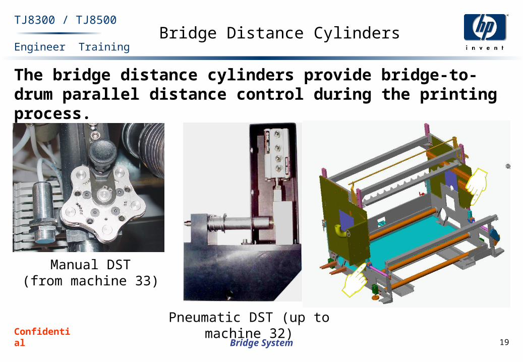
TJ8300 / TJ8500Bridge Distance Cylinders
The bridge distance cylinders provide bridge-to-drum parallel distance control during the printing process.
Manual DST(from machine 33)
Pneumatic DST (up to machine 32)

Confidential 20
Engineer Training
Bridge System
TJ8300 / TJ8500Bridge Motor and Encoder
Enables the bridge to print at constant speed on theprinting axis.
Print Motor (Y-axis)

Confidential 21
Engineer Training
Bridge System
TJ8300 / TJ8500Bridge Motor and Encoder (Cont.)
The Linear encoder detects the precise movement of the bridge along the printing axis and sends back the pulse count to the GALIL DMC controller.
The Linear encoder has a built-in index for bridge home position.

Confidential 22
Engineer Training
Bridge System
TJ8300 / TJ8500 Bridge Y-Axis Movement (Left-Right Print Axis)
Right chassis roll
Left chassis roll

Confidential 23
Engineer Training
Bridge System
TJ8300 / TJ8500 Bridge Y-Axis Movement (Left-Right Print Axis) – Cont.
The bridge is situated on two chassis rolls: the left, and the right.
The right roll is connected to the chassis print motor(Y-Axis motor) via pulley and timing belt.
By rotating the right chassis roll to CW direction, the bridge moves from right to left.
By rotating the right chassis roll to CCW direction, the bridge moves from left to right.
The Linear encoder counts the pulses/mm during the bridge moment along the print axis and sends feedback to the GALIL DMC board.
Print motor is controlled by the GALIL DMC board via MCDU.
Related Documents