G26 Engine Safety, Operation, Maintenance & Parts Manual LT40 rev. K4.00 - K5.01 LT40HD rev. K6.00 - K7.01 Safety is our #1 concern! Read and understand all safety information and instructions before oper- ating, setting up or maintaining this machine. March 2011 Form #1739

Welcome message from author
This document is posted to help you gain knowledge. Please leave a comment to let me know what you think about it! Share it to your friends and learn new things together.
Transcript
G26 EngineSafety, Operation, Maintenance
& Parts Manual
LT40 rev. K4.00 - K5.01LT40HD rev. K6.00 - K7.01
Safety is our #1 concern! Read and understandall safety information and instructions before oper-ating, setting up or maintaining this machine.
March 2011
Form #1739
©2019
Printed in the United States of America, all rights reserved. No part of this manual may be reproduced in any form by any photographic, electronic, mechanical or other means or used in any information storage and retrieval system without written permission from
Wood-Mizer
8180 West 10th Street
Indianapolis, Indiana 46214
Table of Contents Section-Page
TOC
SECTION 1 ABOUT THIS MANUAL 1-1
SECTION 2 OPERATION 2-2
2.1 Starting The Engine................................................................................2-2
SECTION 3 MAINTENANCE 3-1
3.1 Safety......................................................................................................3-13.2 Cooling System ......................................................................................3-23.3 Air Cleaner .............................................................................................3-23.4 Fuel Filter ...............................................................................................3-23.5 Battery ....................................................................................................3-23.6 Alternator Belt ........................................................................................3-33.7 RPM Adjustments ..................................................................................3-43.8 Miscellaneous Maintenance ...................................................................3-4
SECTION 4 REPLACEMENT PARTS 4-1
4.1 Fuel Tank (G28/G29/G38) .....................................................................4-1LT40 Rev. K4.08+LT40 Super Rev. J7.17+LT40HD Rev. K6.09+LT40HD Super Rev. K3.17+LT50 Rev. A5.17+
4.2 Fuel Tank (G28/G29/G38) .....................................................................4-3LT40 Rev. K4.06 - K4.07LT40 Super Rev. J7.16LT40HD Rev. K6.07 - K6.08LT40HD Super Rev. K3.15 - K3.16LT50 Rev. A5.15 - A5.16
4.3 Fuel Tank (G26/G29/G38) (2010+) .......................................................4-4LT40 Prior to Rev. K4.06LT40 Super Prior to Rev. J7.16LT40HD Prior to Rev. K6.07LT40HD Super Prior to Rev. K3.15LT50 Prior to Rev. A5.15
4.4 Fuel Tank (G26/G29/G38) (Pre-2010)..................................................4-5LT40 Prior to Rev. K4.06LT40 Super Prior to Rev. J7.16LT40HD Prior to Rev. K6.07LT40HD Super Prior to Rev. K3.15LT50 Prior to Rev. A5.15
4.5 Engine Mount Assembly (G28/G29/G38)..............................................4-64.6 Engine Assembly....................................................................................4-74.7 Alternator Assembly (G28/G29) ............................................................4-94.8 Engine Pulley Guards (G28/G29) ........................................................4-11
Table of Contents WMdoc092619 iii
Table of Contents Section-Page
APPENDIX A EFI DIAGNOSTIC INSTRUCTIONS A-1
INDEX I
iv WMdoc092619 Table of Contents
About This Manual
About This Manual WM doc 9/26/19 1-1
1
SECTION 1 ABOUT THIS MANUAL
This manual is provided as a supplement to the equipment manufacturer’s manuals. This manual provides information specific to the use of this equipment on the Wood-Mizer® sawmill. Refer to the sawmill operator’s manual and manufacturer's manual before attempting to operate this equipment.
IMPORTANT! Read the sawmill operator’s manual and engine manu-facturer’s manual for instructions and safety precautions before oper-ating this equipment.
The information and instructions given in this manual do not amend or extend the limited warranties for the equipment given at the time of purchase.
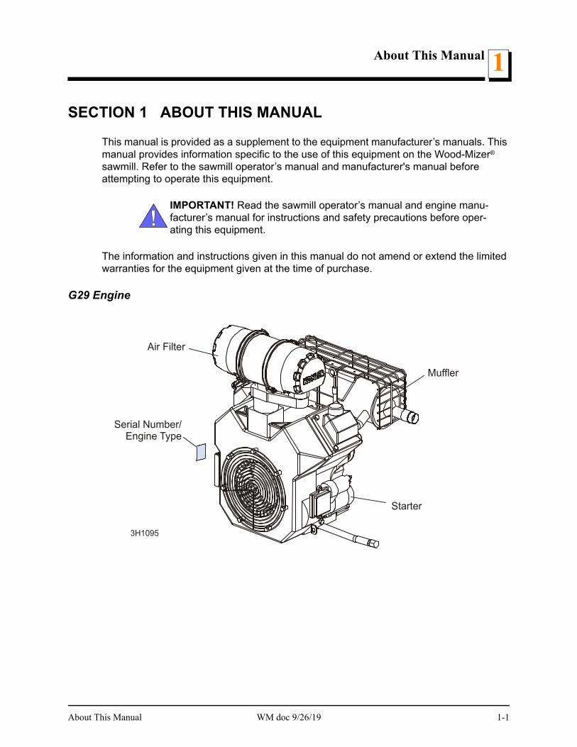
G29 Engine
Air Filter
Muffler
Serial Number/Engine Type
3H1095
Starter
OperationStarting The Engine2
SECTION 2 OPERATION
2.1 Starting The Engine
Engine Control Lights
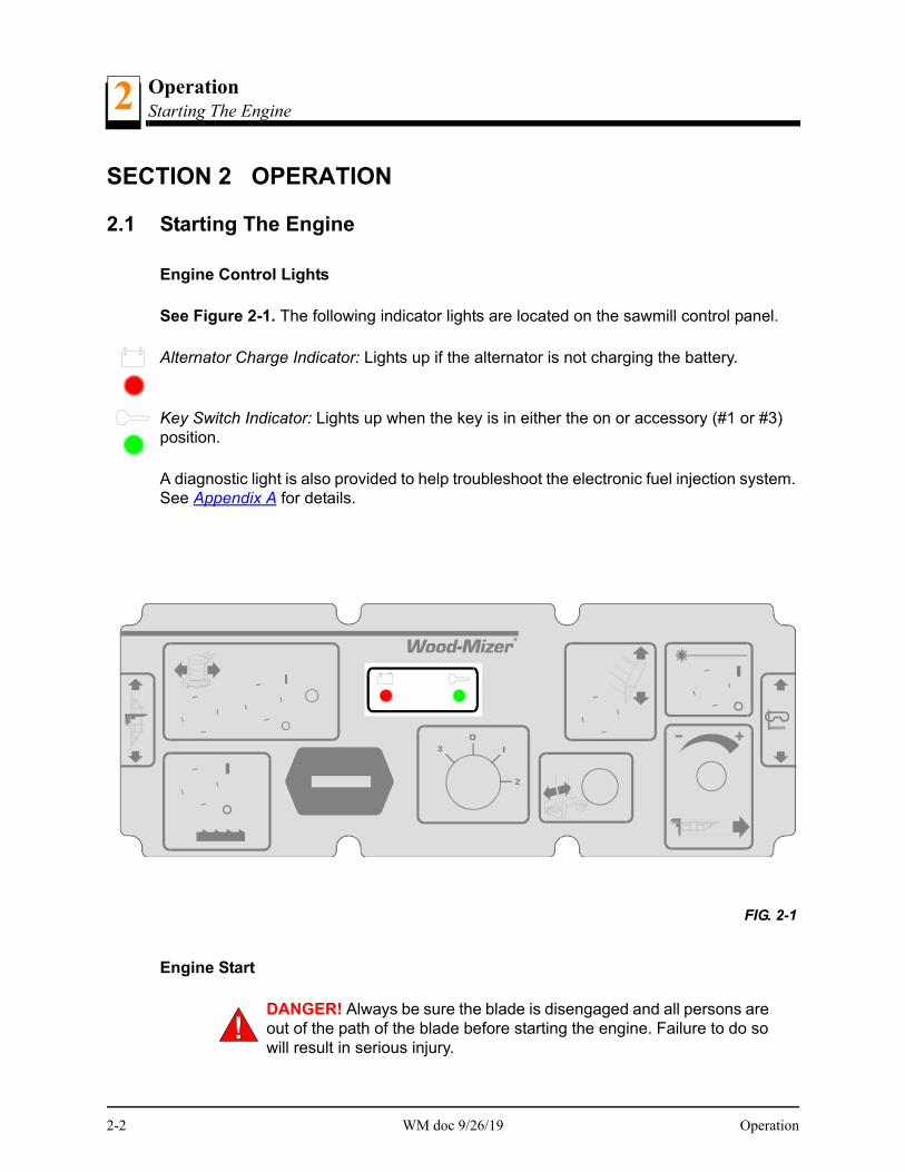
See Figure 2-1. The following indicator lights are located on the sawmill control panel.
Alternator Charge Indicator: Lights up if the alternator is not charging the battery.
Key Switch Indicator: Lights up when the key is in either the on or accessory (#1 or #3) position.
A diagnostic light is also provided to help troubleshoot the electronic fuel injection system. See Appendix A for details.
Engine Start
DANGER! Always be sure the blade is disengaged and all persons are out of the path of the blade before starting the engine. Failure to do so will result in serious injury.
FIG. 2-1
2-2 WM doc 9/26/19 Operation
OperationStarting The Engine 2
DANGER! Operate your engine/machine only in well ventilated areas. The exhaust gases of your engine can cause nausea, delirium and potentially death unless adequate ventilation is present.
DANGER! Never operate an engine with a fuel or oil leak. The leaking fuel or oil could potentially come in contact with hot surfaces and ignite into flames.
WARNING! Be sure the power feed switch is in the neutral position before turning the key switch to the on (#1) or accessory (#3) position. This prevents accidental carriage movement. which may cause serious injury or death.
WARNING! Do not operate engine without proper and operational spark arrester/muffler. Sparks emitted from the engine exhaust could ignite surrounding materials, causing serious injury or death.
WARNING! EPA Compliant Gas Tanks Only: Always relieve all fuel pressure inside the tank prior to filling or connecting fuel fittings. Fail-ure to do so may result in fuel spillage.
WARNING! EPA Compliant Gas Tanks Only: Disconnect the fuel tank when not in use or during transportation. Failure to do so may result in engine flooding or fuel spillage.
Turn the key switch to the start (#2) position and release.
For more information, see the engine manufacturer’s operation manual.
NOTE: When the clutch handle is engaged, an accelerator pump is activated which sup-plies fuel to the engine carburetor. To avoid flooding the carburetor and possibly fouling the spark plugs, do not engage the clutch lever repeatedly without the engine running.
NOTE: If the engine dies after starting, check that the fuel pump is running. If the fuel pump is not running, check the relay inside the black control box on the side of the engine. Check the red wire connecting the relay to the fuel pump for voltage. Also check pin #30 & #86 for 12 volts. If voltage is found at the pins but not the red relay wire, replace the fuel pump relay. If no voltage is found at the pins, have the wiring harness checked by a qualified Kohler technician.
Engine Shutoff
Turn the key switch to the off (#0) position.
Operation WM doc 9/26/19 2-3
MaintenanceSafety3
SECTION 3 MAINTENANCE
Refer to the manufacturer’s manual for maintenance intervals and procedures unless oth-erwise instructed in this manual. Follow the manufacturer’s recommendations for dusty conditions.
IMPORTANT! This manual only provides information about additional procedures or procedures to be performed at different time intervals than found in the manufacturer's manuals. Refer to the manufacturer's manual for complete maintenance instructions.
WARNING! Clean sawdust from all guards, vents, control boxes, or any area where sawdust may gather after every shift. Failure to do so may result in fire, causing death or serious injury.
3.1 Safety
Use caution when performing maintenance or service to the engine.
DANGER! Always be aware of and take proper protective measures against rotating shafts, pulleys, fans, etc. Always stay a safe distance from rotating members and make sure that loose clothing or long hair does not engage rotating members resulting in possible injury.
DANGER! Engine components can become very hot during operation. Avoid contact with any part of a hot engine. The exhaust components of your engine are especially hot during and following operation. Con-tact with hot engine components can cause serious burns. Therefore, never touch or perform service functions on a hot engine. Allow the engine to cool sufficiently before beginning any service function.
WARNING! Remove the blade before performing any engine service. Failure to do so may result in serious injury.
WARNING! Always wear proper and necessary safety equipment when performing service functions. Proper safety equipment includes eye protection, breathing protection, hand protection and foot protec-tion.
This symbol identifies the interval (hours of operation) at which each maintenance pro-cedure should be performed. "AR" signifies maintenance procedures which should be performed as required.
0
3-1 WM doc 9/26/19 Maintenance
MaintenanceCooling System 3
3.2 Cooling System
Wash the engine or brush off sawdust and debris every 50 hours of operation. Clean the grass screen, cooling fins, and external surfaces. Remove any dust, dirt or oil. See engine manual for further instructions.
3.3 Air Cleaner
Empty the air debris collector every 8 hours of operation.
Squeeze the rubber tip of the collector to open it. After all debris has been emptied from the collector, release the tip and allow it to close.
WARNING! Always wear proper and necessary safety equipment when performing service functions. Proper safety equipment includes eye protection, breathing protection, hand protection and foot protec-tion.
Replace the outer air cleaner cartridge and check the inner cartridge every 250 hours of operation or more often if operating the sawmill in dirty conditions or if engine perfor-mance indicates a new cartridge is necessary.
CAUTION! Do not clean elements with water or compressed air. Do not handle the inner element unless it is to be changed. Handle new elements carefully. Contact with the element could cause damage and prevent the filter from operating properly.
Replace the inner air cleaner cartridge every 1200 hours of operation or more often if operating the sawmill in dirty conditions.
3.4 Fuel Filter
Replace the fuel filter every 100 hours of operation or as required for engine perfor-mance.
3.5 Battery
Check the battery electrolyte level every 50 hours of operation. See manufacturer’s man-ual for instructions.
50
8
250
1200
100
50
Maintenance WM doc 9/26/19 3-2

MaintenanceAlternator Belt3
DANGER! Batteries expel explosive gases. Keep sparks, flames, burning cigarettes, or other ignition sources away at all times. Always wear safety goggles and a face shield when working near batteries. Failure to do so will cause serious injury.
WARNING! Battery posts, terminals and related accessories contain lead and lead compounds, chemicals known to the State of California to cause cancer and reproductive harm. Wash hands after handling.
3.6 Alternator Belt
Adjust the alternator belt as needed. Check the alternator belt for tension and wear when battery is not charging properly or when the alternator belt is squealing. To tighten the belt, loosen the adjustment bolt and lock washer. Pivot the alternator away from the motor until the belt has 3/16" (5 mm) deflection with a 5 lb. deflection force. Retighten the adjust-ment bolt.
See Figure 3-1.
FIG. 3-1
AR
3H0227
Loosen bolt topivot alternatorclockwise andtighten belt
3-3 WM doc 9/26/19 Maintenance
MaintenanceRPM Adjustments 3
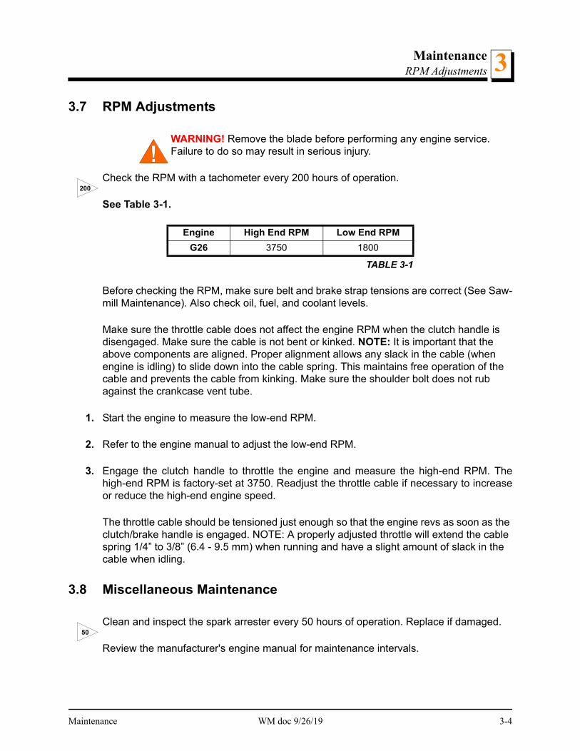
3.7 RPM Adjustments
WARNING! Remove the blade before performing any engine service. Failure to do so may result in serious injury.
Check the RPM with a tachometer every 200 hours of operation.
See Table 3-1.
Before checking the RPM, make sure belt and brake strap tensions are correct (See Saw-mill Maintenance). Also check oil, fuel, and coolant levels.
Make sure the throttle cable does not affect the engine RPM when the clutch handle is disengaged. Make sure the cable is not bent or kinked. NOTE: It is important that the above components are aligned. Proper alignment allows any slack in the cable (when engine is idling) to slide down into the cable spring. This maintains free operation of the cable and prevents the cable from kinking. Make sure the shoulder bolt does not rub against the crankcase vent tube.
1. Start the engine to measure the low-end RPM.
2. Refer to the engine manual to adjust the low-end RPM.
3. Engage the clutch handle to throttle the engine and measure the high-end RPM. Thehigh-end RPM is factory-set at 3750. Readjust the throttle cable if necessary to increaseor reduce the high-end engine speed.
The throttle cable should be tensioned just enough so that the engine revs as soon as the clutch/brake handle is engaged. NOTE: A properly adjusted throttle will extend the cable spring 1/4” to 3/8” (6.4 - 9.5 mm) when running and have a slight amount of slack in the cable when idling.
3.8 Miscellaneous Maintenance
Clean and inspect the spark arrester every 50 hours of operation. Replace if damaged.
Review the manufacturer's engine manual for maintenance intervals.
Engine High End RPM Low End RPM
G26 3750 1800
TABLE 3-1
200
50
Maintenance WM doc 9/26/19 3-4
Replacement PartsFuel Tank (G28/G29/G38) G264
SECTION 4 REPLACEMENT PARTS
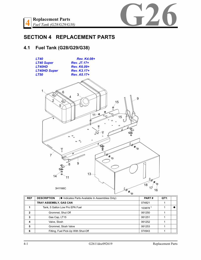
4.1 Fuel Tank (G28/G29/G38)
LT40 Rev. K4.08+LT40 Super Rev. J7.17+LT40HD Rev. K6.09+LT40HD Super Rev. K3.17+LT50 Rev. A5.17+
REF DESCRIPTION ( Indicates Parts Available In Assemblies Only) PART # QTY.
TRAY ASSEMBLY, GAS CAN 074821 1
1 Tank, 5 Gallon Low Pro EPA Fuel 103878 1 1
2 Grommet, Shut Off 061250 1
3 Gas Cap, LT15 061251 1
4 Valve, Slosh 061252 1
5 Grommet, Slosh Valve 061253 1
6 Fitting, Fuel Pick-Up With Shut-Off 074943 1
13
2
5
4
6
13
7
9
3H1166C
15
1718
16
15
9
14
8
12
11
11
4-1 G2611doc092619 Replacement Parts
Replacement PartsFuel Tank (G28/G29/G38)G26 4
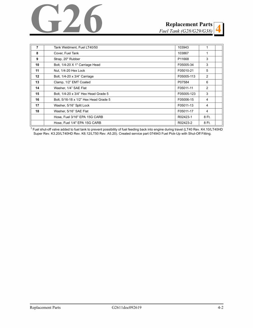
7 Tank Weldment, Fuel LT40/50 103943 1
8 Cover, Fuel Tank 103867 1
9 Strap, 20" Rubber P11668 3
10 Bolt, 1/4-20 X 1" Carriage Head F05005-34 3
11 Nut, 1/4-20 Hex Lock F05010-21 5
12 Bolt, 1/4-20 x 3/4” Carriage F05005-113 2
13 Clamp, 1/2” EMT Coated P07584 6
14 Washer, 1/4” SAE Flat F05011-11 2
15 Bolt, 1/4-20 x 3/4” Hex Head Grade 5 F05005-123 3
16 Bolt, 5/16-18 x 1/2” Hex Head Grade 5 F05006-15 4
17 Washer, 5/16” Split Lock F05011-13 4
18 Washer, 5/16” SAE Flat F05011-17 4
Hose, Fuel 3/16" EPA 15G CARB R02423-1 8 Ft.
Hose, Fuel 1/4" EPA 15G CARB R02423-2 8 Ft.
1 Fuel shut-off valve added to fuel tank to prevent possibility of fuel feeding back into engine during travel (LT40 Rev. K4.10/LT40HDSuper Rev. K3.20/LT40HD Rev. K6.12/LT50 Rev. A5.20). Created service part 074943 Fuel Pick-Up with Shut-Off Fitting.
Replacement Parts G2611doc092619 4-2
Replacement PartsFuel Tank (G28/G29/G38) G264
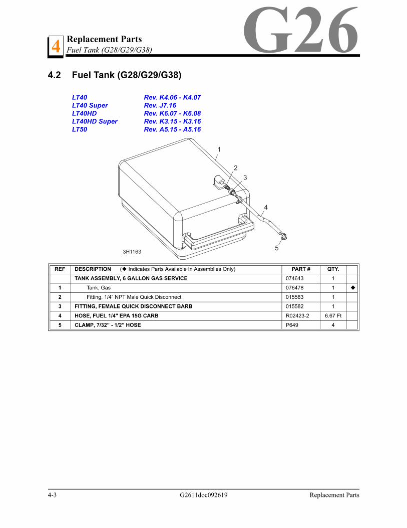
4.2 Fuel Tank (G28/G29/G38)
LT40 Rev. K4.06 - K4.07LT40 Super Rev. J7.16LT40HD Rev. K6.07 - K6.08LT40HD Super Rev. K3.15 - K3.16LT50 Rev. A5.15 - A5.16
REF DESCRIPTION ( Indicates Parts Available In Assemblies Only) PART # QTY.
TANK ASSEMBLY, 6 GALLON GAS SERVICE 074643 1
1 Tank, Gas 076478 1
2 Fitting, 1/4” NPT Male Quick Disconnect 015583 1
3 FITTING, FEMALE QUICK DISCONNECT BARB 015582 1
4 HOSE, FUEL 1/4" EPA 15G CARB R02423-2 6.67 Ft
5 CLAMP, 7/32” - 1/2” HOSE P649 4
1
2
3
4
53H1163
4-3 G2611doc092619 Replacement Parts

Replacement PartsFuel Tank (G26/G29/G38) (2010+)G26 4
4.3 Fuel Tank (G26/G29/G38) (2010+)
LT40 Prior to Rev. K4.06LT40 Super Prior to Rev. J7.16LT40HD Prior to Rev. K6.07LT40HD Super Prior to Rev. K3.15LT50 Prior to Rev. A5.15
REF DESCRIPTION ( Indicates Parts Available In Assemblies Only) PART # QTY.
TANK ASSEMBLY, 6 GALLON GAS SERVICE 074643 1
1 Customers with sawmills and edgers manufactured in 2010 and later need to use new EPA approved 3 or 6 gallon gas can assem-blies (see technical bulletin TB150005 for more information). 5 gallon gas can assemblies are available only for customers withsawmills and edgers manufactured prior to 2010 (See Section 4.4).
1
1 Tank, Gas 076478 1
2 Fitting, 1/4” NPT Male Quick Disconnect 015583 1
3 FITTING, FEMALE QUICK DISCONNECT BARB 015582 1
4 HOSE, FUEL 1/4" EPA 15G CARB R02423-2 6.67 Ft
5 CLAMP, 7/32” - 1/2” HOSE P649 4
1
2
3
4
53H1163-2
Replacement Parts G2611doc092619 4-4
Replacement PartsFuel Tank (G26/G29/G38) (Pre-2010) G264
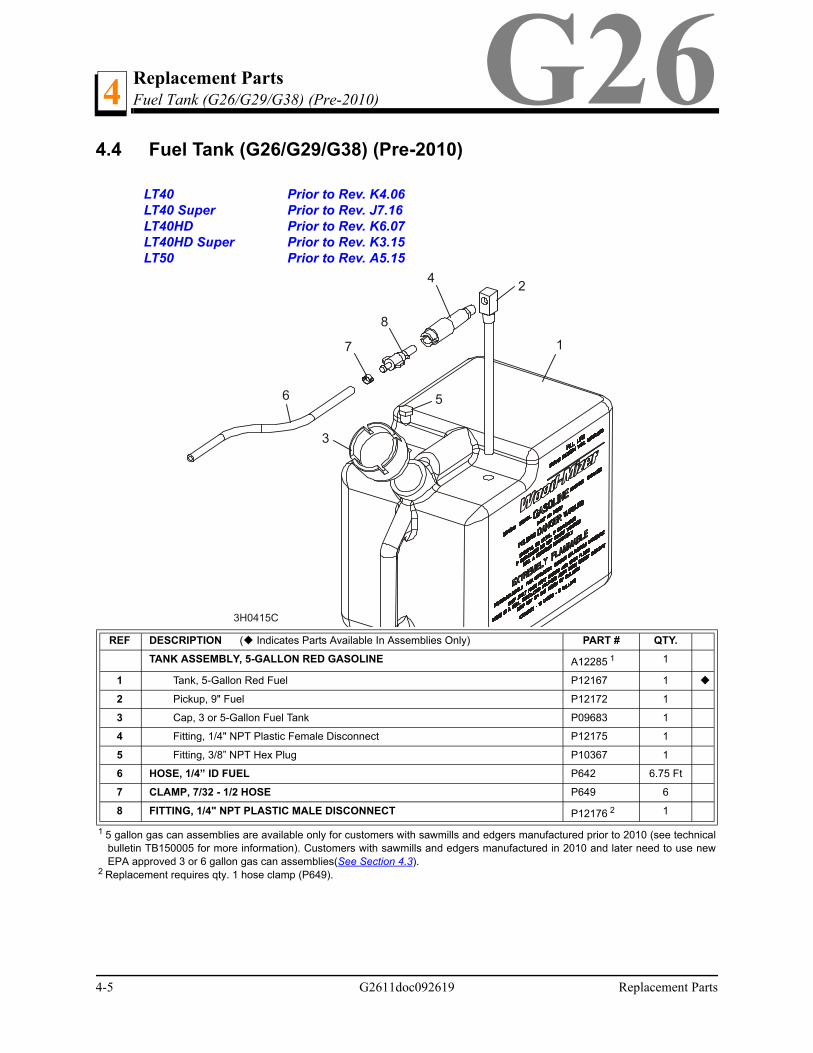
4.4 Fuel Tank (G26/G29/G38) (Pre-2010)
LT40 Prior to Rev. K4.06LT40 Super Prior to Rev. J7.16LT40HD Prior to Rev. K6.07LT40HD Super Prior to Rev. K3.15LT50 Prior to Rev. A5.15
REF DESCRIPTION ( Indicates Parts Available In Assemblies Only) PART # QTY.
TANK ASSEMBLY, 5-GALLON RED GASOLINE A12285 1
1 5 gallon gas can assemblies are available only for customers with sawmills and edgers manufactured prior to 2010 (see technicalbulletin TB150005 for more information). Customers with sawmills and edgers manufactured in 2010 and later need to use newEPA approved 3 or 6 gallon gas can assemblies(See Section 4.3).
1
1 Tank, 5-Gallon Red Fuel P12167 1
2 Pickup, 9" Fuel P12172 1
3 Cap, 3 or 5-Gallon Fuel Tank P09683 1
4 Fitting, 1/4" NPT Plastic Female Disconnect P12175 1
5 Fitting, 3/8” NPT Hex Plug P10367 1
6 HOSE, 1/4” ID FUEL P642 6.75 Ft
7 CLAMP, 7/32 - 1/2 HOSE P649 6
8 FITTING, 1/4" NPT PLASTIC MALE DISCONNECT P12176 2
2 Replacement requires qty. 1 hose clamp (P649).
1
1
2
3
4
8
7
6
3H0415C
5
4-5 G2611doc092619 Replacement Parts
Replacement PartsEngine Mount Assembly (G28/G29/G38)
Replacement Parts G2611doc092619 4-6
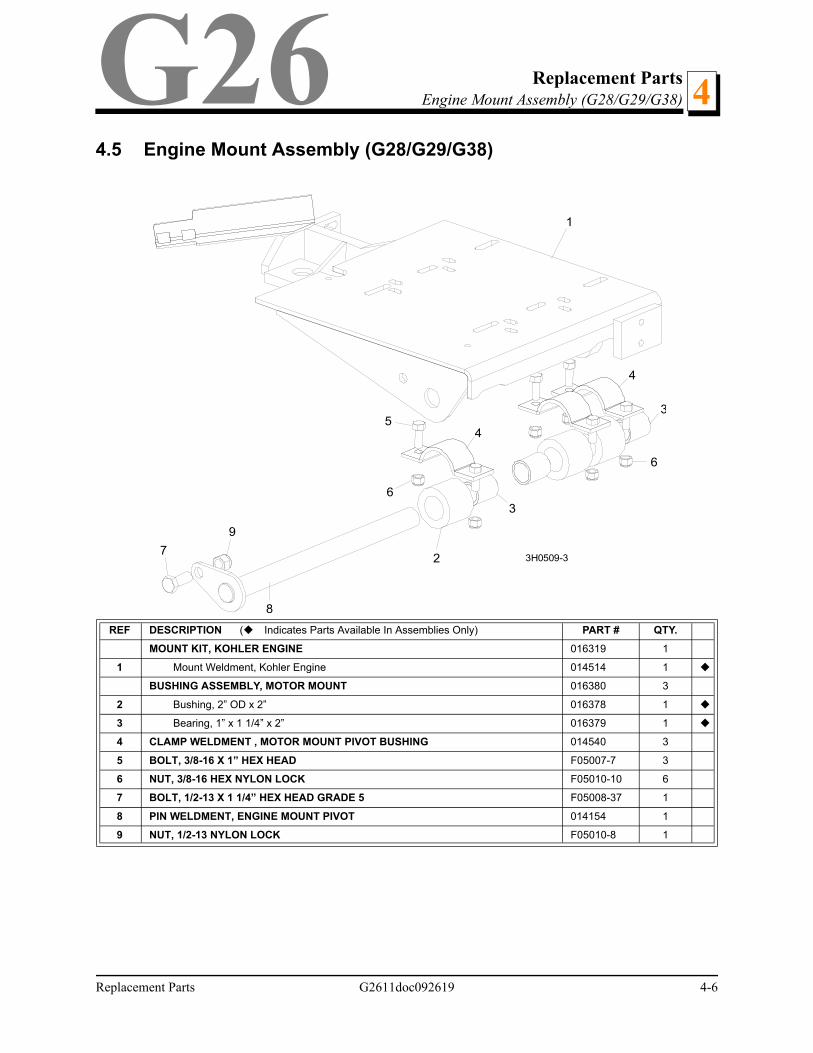
4G264.5 Engine Mount Assembly (G28/G29/G38)
REF DESCRIPTION (Indicates Parts Available In Assemblies Only) PART # QTY.
MOUNT KIT, KOHLER ENGINE 016319 1
1 Mount Weldment, Kohler Engine 014514 1
BUSHING ASSEMBLY, MOTOR MOUNT 016380 3
2 Bushing, 2” OD x 2” 016378 1
3 Bearing, 1” x 1 1/4” x 2” 016379 1
4 CLAMP WELDMENT , MOTOR MOUNT PIVOT BUSHING 014540 3
5 BOLT, 3/8-16 X 1” HEX HEAD F05007-7 3
6 NUT, 3/8-16 HEX NYLON LOCK F05010-10 6
7 BOLT, 1/2-13 X 1 1/4” HEX HEAD GRADE 5 F05008-37 1
8 PIN WELDMENT, ENGINE MOUNT PIVOT 014154 1
9 NUT, 1/2-13 NYLON LOCK F05010-8 1
1
2
3
3
4
45
6
6
7
8
9
3H0509-3
Replacement PartsEngine Assembly4 G26
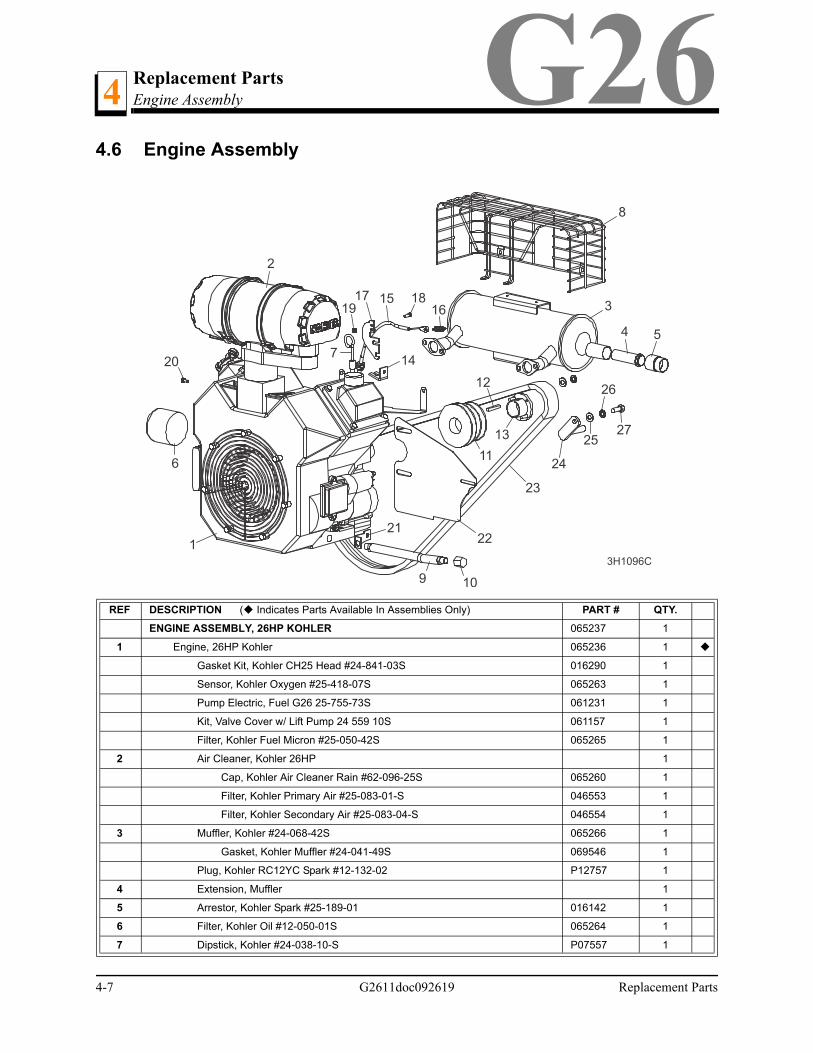
4.6 Engine Assembly
REF DESCRIPTION ( Indicates Parts Available In Assemblies Only) PART # QTY.
ENGINE ASSEMBLY, 26HP KOHLER 065237 1
1 Engine, 26HP Kohler 065236 1
Gasket Kit, Kohler CH25 Head #24-841-03S 016290 1
Sensor, Kohler Oxygen #25-418-07S 065263 1
Pump Electric, Fuel G26 25-755-73S 061231 1
Kit, Valve Cover w/ Lift Pump 24 559 10S 061157 1
Filter, Kohler Fuel Micron #25-050-42S 065265 1
2 Air Cleaner, Kohler 26HP 1
Cap, Kohler Air Cleaner Rain #62-096-25S 065260 1
Filter, Kohler Primary Air #25-083-01-S 046553 1
Filter, Kohler Secondary Air #25-083-04-S 046554 1
3 Muffler, Kohler #24-068-42S 065266 1
Gasket, Kohler Muffler #24-041-49S 069546 1
Plug, Kohler RC12YC Spark #12-132-02 P12757 1
4 Extension, Muffler 1
5 Arrestor, Kohler Spark #25-189-01 016142 1
6 Filter, Kohler Oil #12-050-01S 065264 1
7 Dipstick, Kohler #24-038-10-S P07557 1
1
3
8
4 5
6
9 10
11
12
13
14
1516
17 1819
2
20
2122
23
24
25
26
27
3H1096C
7
4-7 G2611doc092619 Replacement Parts
Replacement PartsEngine Assembly 4G26
6 Filter, Kohler Oil #12-050-01S 065264 1
7 Dipstick, Kohler #24-038-10-S P07557 1
8 Guard, Muffler G26 24 314 56-S 061376 1
9 Hose, 7" Oil Drain P10082 1
10 Cap, Oil Drain 3/8" Pipe P04332 1
Oil, 10W30 Type CD L04869-1 .5 Gal
11 Pulley, 3-Groove Motor S10435 1
12 Key, 1/4" x 1/4" x 1 11/16" S04124 1
13 Bushing, H 1 7/16” Thick Flange P12962 1
Plate, Key Retainer 128029 1 1
14 Bracket, Throttle Mount S12312 1
15 Cable Assembly, 18” Throttle P12313 1
16 Spring, 1/2” x .08” x 1 3/8” Extension 015952 1
17 Bracket, G25 Throttle 015964 1
18 Screw, #10-24 x 5/8” Indented Hex Head F05004-18 1
19 Nut, #10-24 Hex Self-Locking F05010-14 1
20 Screw, M6 x 12 FT Grade 8-8 Din 933 HHC F05005-99 1
21 Bracket, Kohler MIL 065252 1
Light, Red 12Volt .187 Tabs E20482 1
Assembly, Starter 25 098 21S 061371 1
22 PLATE, G25 REAR ENGINE GUARD 015900 1
23 BELT, 2BXF71 DRIVE 036163 1
24 BRACKET WELDMENT, DRIVE BELT SUPPORT PAINTED 015963 1
25 WASHER, 3/8” SAE FLAT F05011-3 2
26 WASHER, 3/8” SPLIT LOCK F05011-4 2
27 BOLT, 3/8-16 X 1” HEX HEAD F05007-7 11 Added after 7/11/2019 per ECN 35979
Replacement Parts G2611doc092619 4-8
Replacement PartsAlternator Assembly (G28/G29)4 G26
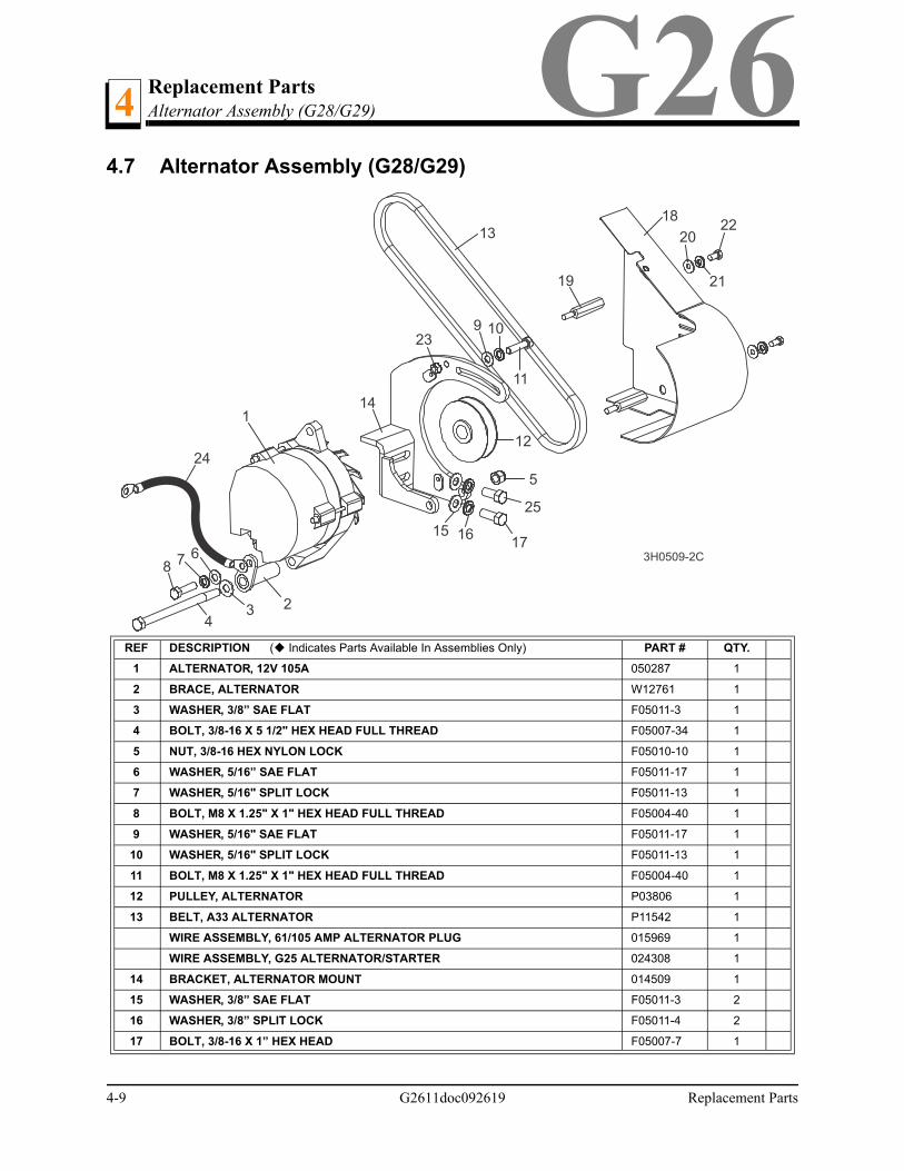
4.7 Alternator Assembly (G28/G29)
REF DESCRIPTION ( Indicates Parts Available In Assemblies Only) PART # QTY.
1 ALTERNATOR, 12V 105A 050287 1
2 BRACE, ALTERNATOR W12761 1
3 WASHER, 3/8” SAE FLAT F05011-3 1
4 BOLT, 3/8-16 X 5 1/2" HEX HEAD FULL THREAD F05007-34 1
5 NUT, 3/8-16 HEX NYLON LOCK F05010-10 1
6 WASHER, 5/16” SAE FLAT F05011-17 1
7 WASHER, 5/16" SPLIT LOCK F05011-13 1
8 BOLT, M8 X 1.25" X 1" HEX HEAD FULL THREAD F05004-40 1
9 WASHER, 5/16" SAE FLAT F05011-17 1
10 WASHER, 5/16" SPLIT LOCK F05011-13 1
11 BOLT, M8 X 1.25" X 1" HEX HEAD FULL THREAD F05004-40 1
12 PULLEY, ALTERNATOR P03806 1
13 BELT, A33 ALTERNATOR P11542 1
WIRE ASSEMBLY, 61/105 AMP ALTERNATOR PLUG 015969 1
WIRE ASSEMBLY, G25 ALTERNATOR/STARTER 024308 1
14 BRACKET, ALTERNATOR MOUNT 014509 1
15 WASHER, 3/8” SAE FLAT F05011-3 2
16 WASHER, 3/8” SPLIT LOCK F05011-4 2
17 BOLT, 3/8-16 X 1” HEX HEAD F05007-7 1
1
234
5
678
9 10
11
12
13
14
15 16 17
25
19
18
20
21
22
23
3H0509-2C
24
4-9 G2611doc092619 Replacement Parts
Replacement PartsAlternator Assembly (G28/G29) 4G26
18 GUARD, ALTERNATOR BELT 014499 1
19 STANDOFF, 1/4-20 X 1 7/8” 015957 2
20 WASHER, 1/4” SAE FLAT F05011-11 2
21 WASHER, 1/4” SPLIT LOCK F05011-14 2
22 BOLT, 1/4-20 X 1/2” HEX HEAD F05005-15 2
23 NUT, 1/4-20 SELF-LOCKING HEX F05010-9 1
24 WIRE ASSEMBLY, GROUND JUMPER 017770 1
25 BOLT, 3/8-16 X 3/4” HEX HEAD F05007-27 1
Replacement Parts G2611doc092619 4-10
Replacement PartsEngine Pulley Guards (G28/G29)4
4-11 G2611doc092619 Replacement Parts
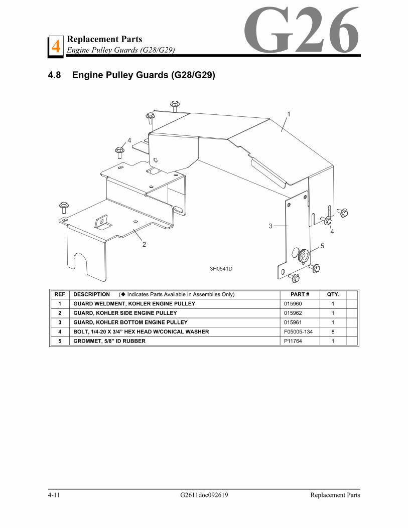
G264.8 Engine Pulley Guards (G28/G29)
REF DESCRIPTION ( Indicates Parts Available In Assemblies Only) PART # QTY.
1 GUARD WELDMENT, KOHLER ENGINE PULLEY 015960 1
2 GUARD, KOHLER SIDE ENGINE PULLEY 015962 1
3 GUARD, KOHLER BOTTOM ENGINE PULLEY 015961 1
4 BOLT, 1/4-20 X 3/4” HEX HEAD W/CONICAL WASHER F05005-134 8
5 GROMMET, 5/8” ID RUBBER P11764 1
4
3H0541D
1
2
3
4
5
APPENDIX A EFI DIAGNOSTIC INSTRUCTIONS
Section 5EFI Fuel System
Troubleshooting
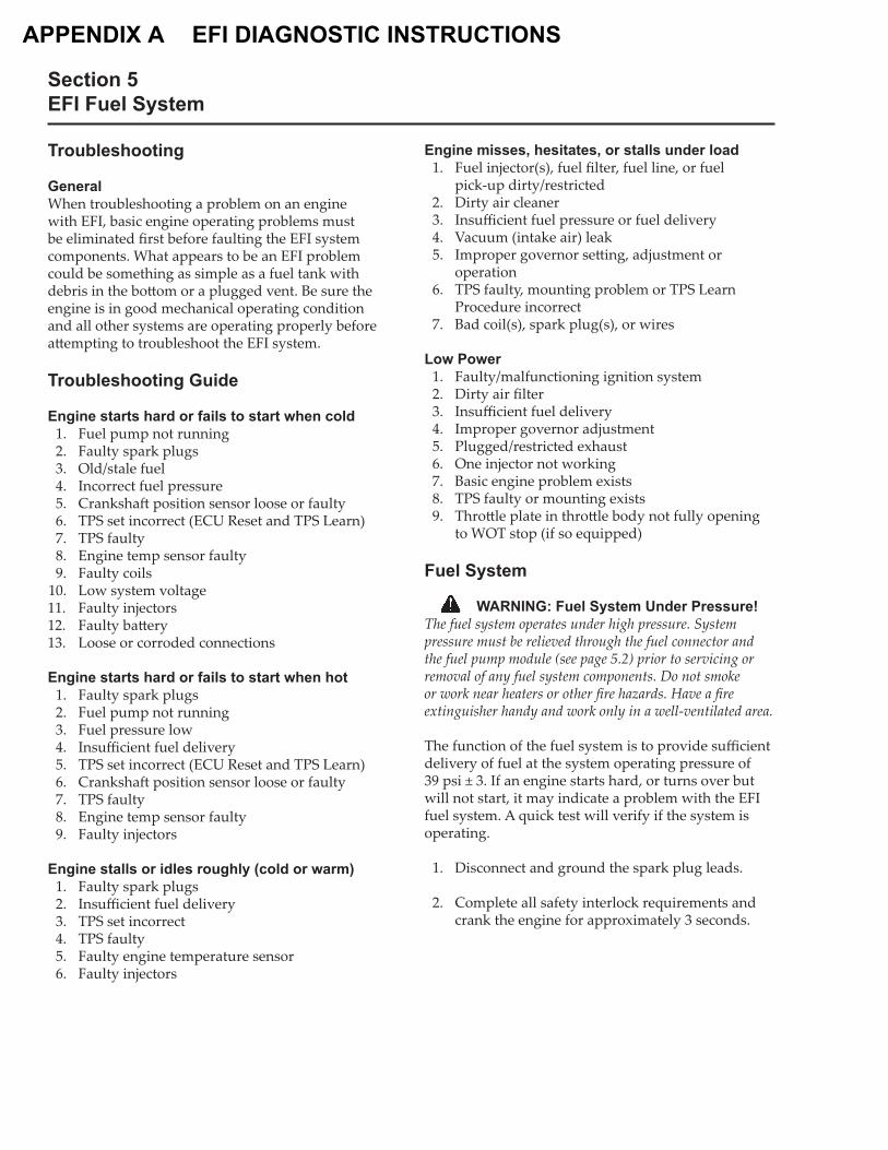
GeneralWhen troubleshooting a problem on an engine with EFI, basic engine operating problems must be eliminated � rst before faulting the EFI system components. What appears to be an EFI problem could be something as simple as a fuel tank with debris in the bo� om or a plugged vent. Be sure the engine is in good mechanical operating condition and all other systems are operating properly before a� empting to troubleshoot the EFI system.
Troubleshooting Guide
Engine starts hard or fails to start when cold 1. Fuel pump not running 2. Faulty spark plugs 3. Old/stale fuel 4. Incorrect fuel pressure 5. Cranksha� position sensor loose or faulty 6. TPS set incorrect (ECU Reset and TPS Learn) 7. TPS faulty 8. Engine temp sensor faulty 9. Faulty coils 10. Low system voltage11. Faulty injectors12. Faulty ba� ery13. Loose or corroded connections
Engine starts hard or fails to start when hot 1. Faulty spark plugs 2. Fuel pump not running 3. Fuel pressure low 4. Insu� cient fuel delivery 5. TPS set incorrect (ECU Reset and TPS Learn) 6. Cranksha� position sensor loose or faulty 7. TPS faulty 8. Engine temp sensor faulty 9. Faulty injectors
Engine stalls or idles roughly (cold or warm) 1. Faulty spark plugs 2. Insu� cient fuel delivery 3. TPS set incorrect 4. TPS faulty 5. Faulty engine temperature sensor 6. Faulty injectors
Engine misses, hesitates, or stalls under load 1. Fuel injector(s), fuel � lter, fuel line, or fuel
pick-up dirty/restricted 2. Dirty air cleaner 3. Insu� cient fuel pressure or fuel delivery 4. Vacuum (intake air) leak 5. Improper governor se� ing, adjustment or
operation 6. TPS faulty, mounting problem or TPS Learn
Procedure incorrect 7. Bad coil(s), spark plug(s), or wires
Low Power 1. Faulty/malfunctioning ignition system 2. Dirty air � lter 3. Insu� cient fuel delivery 4. Improper governor adjustment 5. Plugged/restricted exhaust 6. One injector not working 7. Basic engine problem exists 8. TPS faulty or mounting exists 9. Thro� le plate in thro� le body not fully opening
to WOT stop (if so equipped)
Fuel System
WARNING: Fuel System Under Pressure!The fuel system operates under high pressure. System pressure must be relieved through the fuel connector and the fuel pump module (see page 5.2) prior to servicing or removal of any fuel system components. Do not smoke or work near heaters or other � re hazards. Have a � re extinguisher handy and work only in a well-ventilated area.
The function of the fuel system is to provide su� cient delivery of fuel at the system operating pressure of 39 psi ± 3. If an engine starts hard, or turns over but will not start, it may indicate a problem with the EFI fuel system. A quick test will verify if the system is operating.
1. Disconnect and ground the spark plug leads. 2. Complete all safety interlock requirements and
crank the engine for approximately 3 seconds.
Section 5EFI Fuel System
5
3. Remove the spark plugs and check for fuel at the tips.
a. If there is fuel at the tips of the spark plugs the fuel pump and injectors are operating.
b. If there is no fuel at the tips of the spark plugs, check the following:
1) Make sure the fuel tank contains clean, fresh, proper fuel.
2) Make sure that the vent in the fuel tank is open.
3) Make sure the fuel tank valve (if so equipped) is fully opened.
4) Make sure the ba� ery is supplying proper voltage.
5) Check that the fuses are good, and that no electrical or fuel line connections are damaged or broken.
6) Test fuel pump module operation as described earlier under Fuel Pump – Service.
Fault CodesThe ECU continuously monitors engine operation against preset performance limits. If the operation is outside the limits, the ECU activates the MIL, if equipped, and stores a diagnostic code in its fault memory. If the component or system returns to proper function, the ECU will turn o� the MIL. If the MIL stays illuminated, it warns the customer a fault is currently happening, and dealer service is required. Upon receipt, the dealer technician can access the fault code(s) to help determine what portion of the system is malfunctioning. The 4-digit fault codes available are listed on page 5.29.
The codes are accessed through the key switch and displayed as blinks or � ashes of the MIL. Access the codes as follows:
1. Check that the ba� ery voltage is above 11 volts.
2. Start with the key switch OFF.
3. Turn the key switch to the ON and OFF, then ON and OFF, then ON, leaving it on in the third sequence. Do not start the engine. The time between sequences must be less than 2.5 seconds.
4. The MIL will blink a series of times. The number of times the MIL blinks represents a number in the blink code.
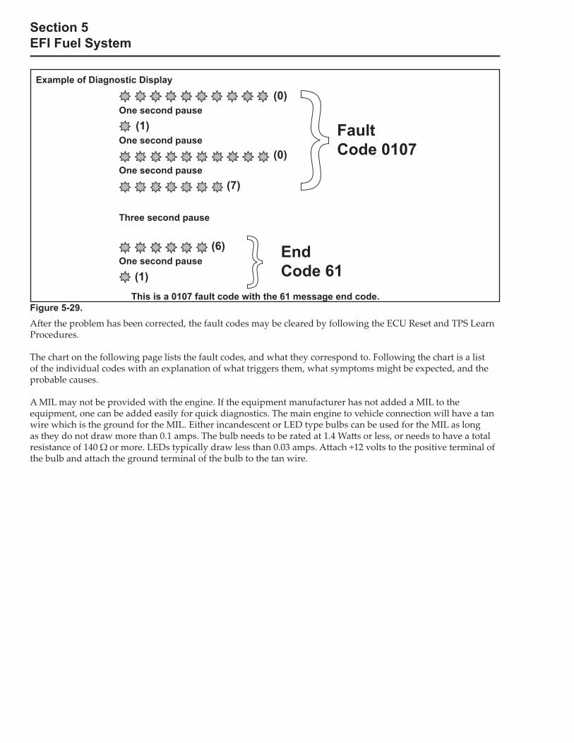
5. A sequence of four digits make up a fault code. There is a one (1) second pause between the blinks of a fault code. There is a three (3) second pause between separate fault codes. A� er the fault code(s) are blinked a two digit 61 is blinked to indicate the program has completed.
a. It’s a good idea to write down the codes as they appear, as they may not be in numerical sequence.
b. Code 61 will always be the last code displayed, indicating the end of code transmission. If code 61 appears immediately, no other fault codes are present.
Section 5EFI Fuel System
A� er the problem has been corrected, the fault codes may be cleared by following the ECU Reset and TPS Learn Procedures.
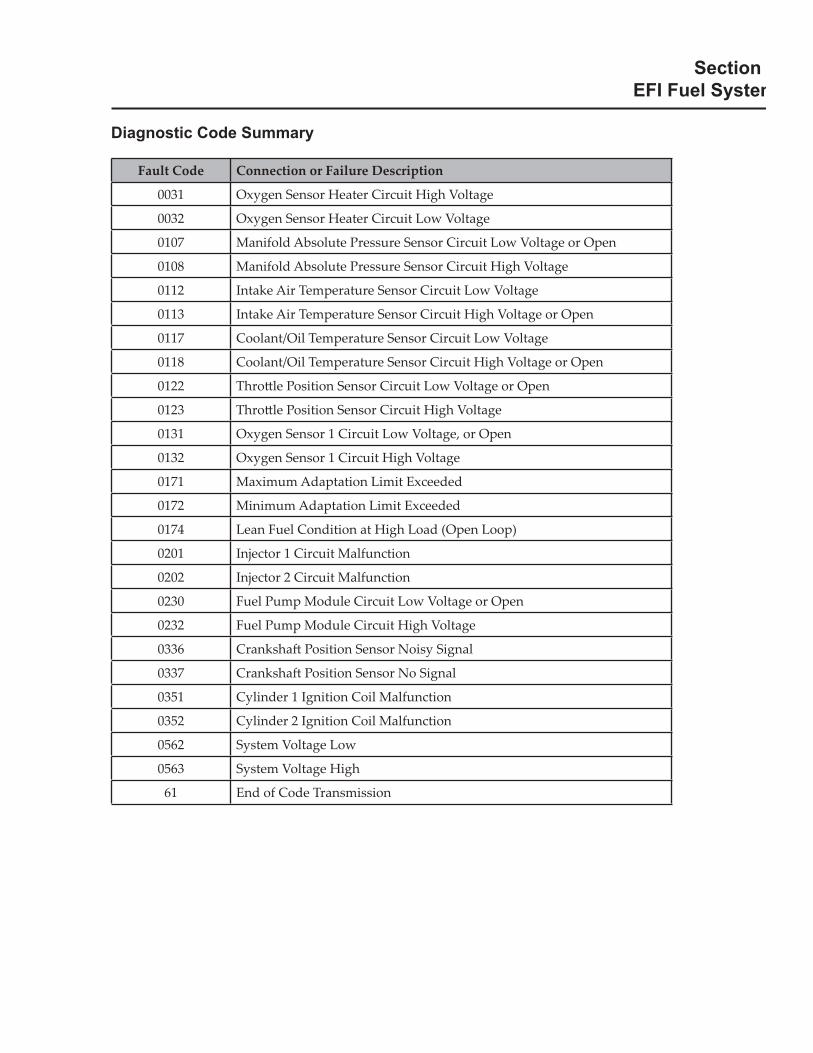
The chart on the following page lists the fault codes, and what they correspond to. Following the chart is a list of the individual codes with an explanation of what triggers them, what symptoms might be expected, and the probable causes.
A MIL may not be provided with the engine. If the equipment manufacturer has not added a MIL to the equipment, one can be added easily for quick diagnostics. The main engine to vehicle connection will have a tan wire which is the ground for the MIL. Either incandescent or LED type bulbs can be used for the MIL as long as they do not draw more than 0.1 amps. The bulb needs to be rated at 1.4 Wa� s or less, or needs to have a total resistance of 140 � or more. LEDs typically draw less than 0.03 amps. Attach +12 volts to the positive terminal of the bulb and attach the ground terminal of the bulb to the tan wire.
Example of Diagnostic Display
This is a 0107 fault code with the 61 message end code. Figure 5-29.
One second pause
One second pause
One second pause
One second pause
Three second pause
(0)
(0)
(7)
(6)
(1)
(1)
EndCode 61
FaultCode 0107
Section EFI Fuel System
Diagnostic Code Summary
Fault Code Connection or Failure Description
0031 Oxygen Sensor Heater Circuit High Voltage
0032 Oxygen Sensor Heater Circuit Low Voltage
0107 Manifold Absolute Pressure Sensor Circuit Low Voltage or Open
0108 Manifold Absolute Pressure Sensor Circuit High Voltage
0112 Intake Air Temperature Sensor Circuit Low Voltage
0113 Intake Air Temperature Sensor Circuit High Voltage or Open
0117 Coolant/Oil Temperature Sensor Circuit Low Voltage
0118 Coolant/Oil Temperature Sensor Circuit High Voltage or Open
0122 Thro� le Position Sensor Circuit Low Voltage or Open
0123 Thro� le Position Sensor Circuit High Voltage
0131 Oxygen Sensor 1 Circuit Low Voltage, or Open
0132 Oxygen Sensor 1 Circuit High Voltage
0171 Maximum Adaptation Limit Exceeded
0172 Minimum Adaptation Limit Exceeded
0174 Lean Fuel Condition at High Load (Open Loop)
0201 Injector 1 Circuit Malfunction
0202 Injector 2 Circuit Malfunction
0230 Fuel Pump Module Circuit Low Voltage or Open
0232 Fuel Pump Module Circuit High Voltage
0336 Cranksha� Position Sensor Noisy Signal
0337 Cranksha� Position Sensor No Signal
0351 Cylinder 1 Ignition Coil Malfunction
0352 Cylinder 2 Ignition Coil Malfunction
0562 System Voltage Low
0563 System Voltage High
61 End of Code Transmission

Section 5EFI Fuel System
Code: 0031
Component: Oxygen Sensor Heater
Fault: O2S Heater Circuit High VoltageCondition: System voltage too high, shorted connection or faulty sensor.
Possible Causes: 1. Oxygen Sensor Related a. Sensor connector or wiring problem. b. Sensor damaged. c. Pin circuit wiring or connectors at Black 7.
2. ECU Related a. ECU-to-harness connection problem.
Code: 0032
Component: Oxygen Sensor Heater
Fault: O2S Heater Circuit Low VoltageCondition: System voltage too low, open connection or faulty sensor.
Possible Causes: 1. Engine Wiring Harness Related a. Pin circuit wiring or connectors. 1. ECU Black pin 7. 2. Broken wire.
2. Oxygen Sensor Related a. Sensor connector or wiring problem.
3. Poor system ground from ECU to engine or ba� ery to engine.
Code: 0107
Component: Manifold Absolute Pressure Sensor
Fault: MAP Circuit Low Voltage or OpenCondition: Intake manifold leak, open connection or faulty sensor.
Possible Causes: 1. MAP Sensor Related a. Sensor malfunction. b. Vacuum leaks from loose manifold or sensor.
2. Wire Harness Related a. Poor grounding or open circuit. b. Wire harness and connectors loose, damaged
or corroded. c. Pin circuit wiring or connectors at Black 10, 11
and 16.
3. Bad TPS Learn.
Code: 0108
Component: Manifold Absolute Pressure Sensor
Fault: MAP Circuit High VoltageCondition: Intake manifold leak, shorted connection or faulty sensor.
Possible Causes: 1. MAP Sensor Related a. Sensor malfunction. b. Vacuum leaks from loose manifold or sensor.
2. Wire Harness Related a. Poor grounding. b. Pin circuit wiring or connectors at Black 11.
3. Bad TPS Learn.
Code: 0112
Component: Intake Air Temperature Sensor
Fault: Intake Air Temperature Sensor Circuit Low Voltage
Condition: Shorted connection, faulty sensor or shorted wire.
Possible Causes: 1. Temperature Sensor Related a. Sensor wiring or connection.
2. Engine Wiring Harness Related a. Pin circuits Black 10 and Black 8 may be
damaged or routed near noisy signal (coils, alternator, etc.).
b. ECU-to-harness connection problem.
Code: 0113
Component: Intake Air Temperature Sensor
Fault: Intake Air Temperature Sensor Circuit High Voltage or Open
Condition: Shorted connection, faulty sensor, broken wire or connection.
Possible Causes: 1. Temperature Sensor Related a. Sensor wiring or connection.
2. Engine Wiring Harness Related a. Pin circuits ECU Black pin 10 and 8 may be
damaged. b. ECU-to-harness connection problem or
broken wire.
Section 5EFI Fuel System
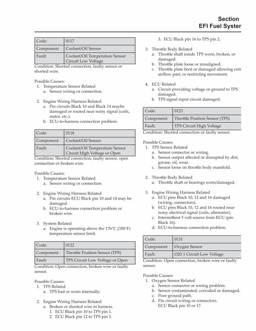
Code: 0117
Component: Coolant/Oil Sensor
Fault: Coolant/Oil Temperature Sensor Circuit Low Voltage
Condition: Shorted connection, faulty sensor or shorted wire.
Possible Causes: 1. Temperature Sensor Related a. Sensor wiring or connection.
2. Engine Wiring Harness Related a. Pin circuits Black 10 and Black 14 maybe
damaged or routed near noisy signal (coils, stator, etc.).
b. ECU-to-harness connection problem.
Code: 0118
Component: Coolant/Oil Sensor
Fault: Coolant/Oil Temperature Sensor Circuit High Voltage or Open
Condition: Shorted connection, faulty sensor, open connection or broken wire.
Possible Causes: 1. Temperature Sensor Related a. Sensor wiring or connection.
2. Engine Wiring Harness Related a. Pin circuits ECU Black pin 10 and 14 may be
damaged. b. ECU-to-harness connection problem or
broken wire.
3. System Related a. Engine is operating above the 176°C (350°F)
temperature sensor limit.
Code: 0122
Component: Thro� le Position Sensor (TPS)
Fault: TPS Circuit Low Voltage or OpenCondition: Open connection, broken wire or faulty sensor.
Possible Causes: 1. TPS Related a. TPS bad or worn internally.
2. Engine Wiring Harness Related a. Broken or shorted wire in harness. 1. ECU Black pin 10 to TPS pin 1. 2. ECU Black pin 12 to TPS pin 3.
3. ECU Black pin 16 to TPS pin 2.
3. Thro� le Body Related a. Thro� le sha� inside TPS worn, broken, or
damaged. b. Thro� le plate loose or misaligned. c. Thro� le plate bent or damaged allowing extr
air� ow past, or restricting movement.
4. ECU Related a. Circuit providing voltage or ground to TPS
damaged. b. TPS signal input circuit damaged.
Code: 0123
Component: Thro� le Position Sensor (TPS)
Fault: TPS Circuit High VoltageCondition: Shorted connection or faulty sensor.
Possible Causes: 1. TPS Sensor Related a. Sensor connector or wiring. b. Sensor output a� ected or disrupted by dirt,
grease, oil, wear. c. Sensor loose on thro� le body manifold.
2. Thro� le Body Related a. Thro� le sha� or bearings worn/damaged.
3. Engine Wiring Harness Related a. ECU pins Black 10, 12 and 16 damaged
(wiring, connectors). b. ECU pins Black 10, 12 and 16 routed near
noisy electrical signal (coils, alternator). c. Intermi� ent 5 volt source from ECU (pin
Black 16). d. ECU-to-harness connection problem.
Code: 0131
Component: Oxygen Sensor
Fault: O2S 1 Circuit Low VoltageCondition: Open connection, broken wire or faulty sensor.
Possible Causes: 1. Oxygen Sensor Related a. Sensor connector or wiring problem. b. Sensor contaminated, corroded or damaged. c. Poor ground path. d. Pin circuit wiring or connectors. ECU Black pin 10 or 17.
Section 5EFI Fuel System
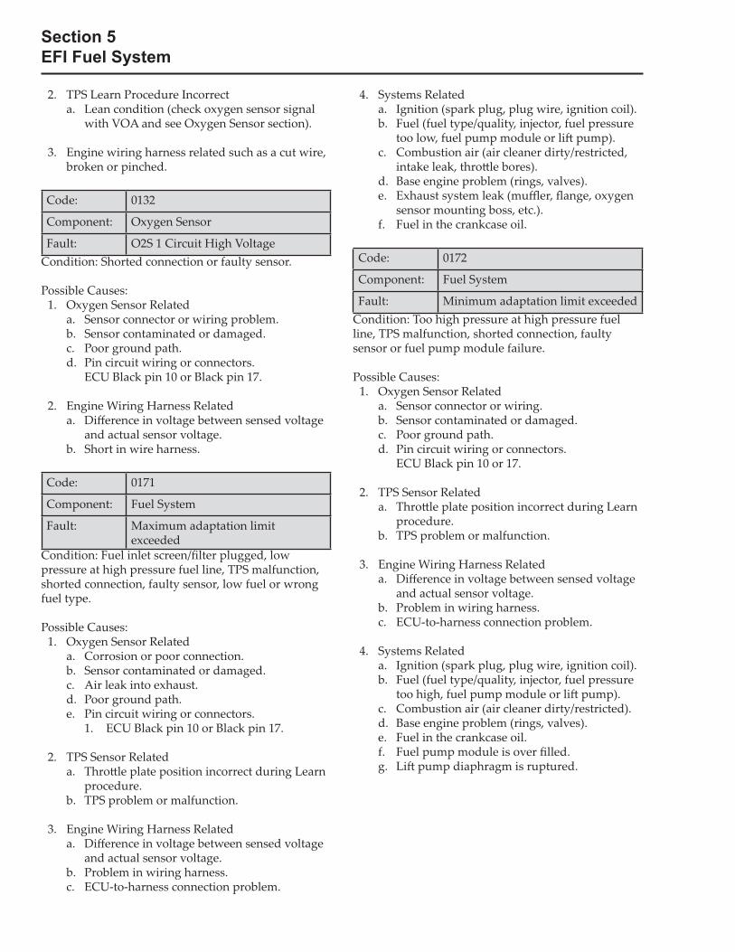
2. TPS Learn Procedure Incorrect a. Lean condition (check oxygen sensor signal
with VOA and see Oxygen Sensor section).
3. Engine wiring harness related such as a cut wire, broken or pinched.
Code: 0132
Component: Oxygen Sensor
Fault: O2S 1 Circuit High VoltageCondition: Shorted connection or faulty sensor.
Possible Causes: 1. Oxygen Sensor Related a. Sensor connector or wiring problem. b. Sensor contaminated or damaged. c. Poor ground path. d. Pin circuit wiring or connectors. ECU Black pin 10 or Black pin 17.
2. Engine Wiring Harness Related a. Di� erence in voltage between sensed voltage
and actual sensor voltage. b. Short in wire harness.
Code: 0171
Component: Fuel System
Fault: Maximum adaptation limit exceeded
Condition: Fuel inlet screen/� lter plugged, low pressure at high pressure fuel line, TPS malfunction, shorted connection, faulty sensor, low fuel or wrong fuel type.
Possible Causes: 1. Oxygen Sensor Related a. Corrosion or poor connection. b. Sensor contaminated or damaged. c. Air leak into exhaust. d. Poor ground path. e. Pin circuit wiring or connectors. 1. ECU Black pin 10 or Black pin 17.
2. TPS Sensor Related a. Thro� le plate position incorrect during Learn
procedure. b. TPS problem or malfunction.
3. Engine Wiring Harness Related a. Di� erence in voltage between sensed voltage
and actual sensor voltage. b. Problem in wiring harness. c. ECU-to-harness connection problem.
4. Systems Related a. Ignition (spark plug, plug wire, ignition coil). b. Fuel (fuel type/quality, injector, fuel pressure
too low, fuel pump module or li� pump). c. Combustion air (air cleaner dirty/restricted,
intake leak, thro� le bores). d. Base engine problem (rings, valves). e. Exhaust system leak (mu er, � ange, oxygen
sensor mounting boss, etc.). f. Fuel in the crankcase oil.
Code: 0172
Component: Fuel System
Fault: Minimum adaptation limit exceededCondition: Too high pressure at high pressure fuel line, TPS malfunction, shorted connection, faulty sensor or fuel pump module failure.
Possible Causes: 1. Oxygen Sensor Related a. Sensor connector or wiring. b. Sensor contaminated or damaged. c. Poor ground path. d. Pin circuit wiring or connectors. ECU Black pin 10 or 17.
2. TPS Sensor Related a. Thro� le plate position incorrect during Learn
procedure. b. TPS problem or malfunction.
3. Engine Wiring Harness Related a. Di� erence in voltage between sensed voltage
and actual sensor voltage. b. Problem in wiring harness. c. ECU-to-harness connection problem.
4. Systems Related a. Ignition (spark plug, plug wire, ignition coil). b. Fuel (fuel type/quality, injector, fuel pressure
too high, fuel pump module or li� pump). c. Combustion air (air cleaner dirty/restricted). d. Base engine problem (rings, valves). e. Fuel in the crankcase oil. f. Fuel pump module is over � lled. g. Li� pump diaphragm is ruptured.
Section 5EFI Fuel System
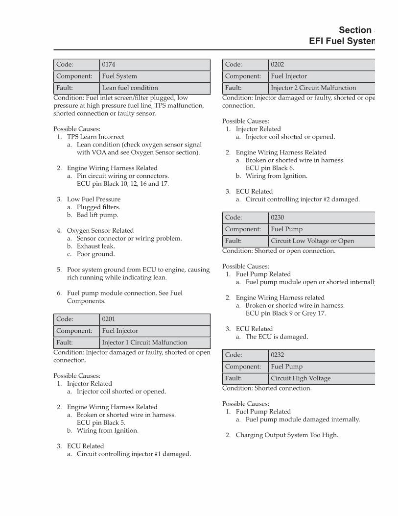
Code: 0174
Component: Fuel System
Fault: Lean fuel conditionCondition: Fuel inlet screen/� lter plugged, low pressure at high pressure fuel line, TPS malfunction, shorted connection or faulty sensor.
Possible Causes: 1. TPS Learn Incorrect a. Lean condition (check oxygen sensor signal
with VOA and see Oxygen Sensor section).
2. Engine Wiring Harness Related a. Pin circuit wiring or connectors. ECU pin Black 10, 12, 16 and 17.
3. Low Fuel Pressure a. Plugged � lters. b. Bad li� pump.
4. Oxygen Sensor Related a. Sensor connector or wiring problem. b. Exhaust leak. c. Poor ground.
5. Poor system ground from ECU to engine, causing rich running while indicating lean.
6. Fuel pump module connection. See Fuel Components.
Code: 0201
Component: Fuel Injector
Fault: Injector 1 Circuit MalfunctionCondition: Injector damaged or faulty, shorted or open connection.
Possible Causes: 1. Injector Related a. Injector coil shorted or opened.
2. Engine Wiring Harness Related a. Broken or shorted wire in harness. ECU pin Black 5. b. Wiring from Ignition.
3. ECU Related a. Circuit controlling injector #1 damaged.
Code: 0202
Component: Fuel Injector
Fault: Injector 2 Circuit MalfunctionCondition: Injector damaged or faulty, shorted or opeconnection.
Possible Causes: 1. Injector Related a. Injector coil shorted or opened.
2. Engine Wiring Harness Related a. Broken or shorted wire in harness. ECU pin Black 6. b. Wiring from Ignition.
3. ECU Related a. Circuit controlling injector #2 damaged.
Code: 0230
Component: Fuel Pump
Fault: Circuit Low Voltage or OpenCondition: Shorted or open connection.
Possible Causes: 1. Fuel Pump Related a. Fuel pump module open or shorted internally
2. Engine Wiring Harness related a. Broken or shorted wire in harness. ECU pin Black 9 or Grey 17.
3. ECU Related a. The ECU is damaged.
Code: 0232
Component: Fuel Pump
Fault: Circuit High VoltageCondition: Shorted connection.
Possible Causes: 1. Fuel Pump Related a. Fuel pump module damaged internally.
2. Charging Output System Too High.
Section 5EFI Fuel System
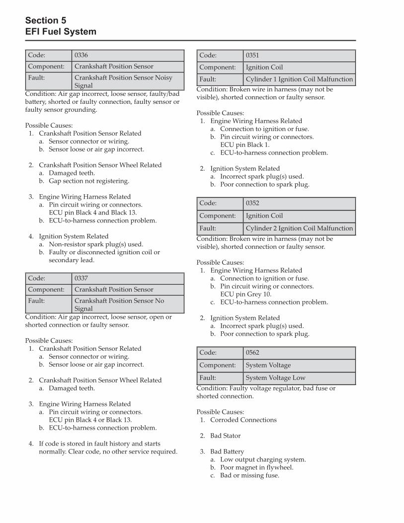
Code: 0336
Component: Cranksha� Position Sensor
Fault: Cranksha� Position Sensor Noisy Signal
Condition: Air gap incorrect, loose sensor, faulty/bad ba� ery, shorted or faulty connection, faulty sensor or faulty sensor grounding.
Possible Causes: 1. Cranksha� Position Sensor Related a. Sensor connector or wiring. b. Sensor loose or air gap incorrect.
2. Cranksha� Position Sensor Wheel Related a. Damaged teeth. b. Gap section not registering.
3. Engine Wiring Harness Related a. Pin circuit wiring or connectors. ECU pin Black 4 and Black 13. b. ECU-to-harness connection problem.
4. Ignition System Related a. Non-resistor spark plug(s) used. b. Faulty or disconnected ignition coil or
secondary lead.
Code: 0337
Component: Cranksha� Position Sensor
Fault: Cranksha� Position Sensor No Signal
Condition: Air gap incorrect, loose sensor, open or shorted connection or faulty sensor.
Possible Causes: 1. Cranksha� Position Sensor Related a. Sensor connector or wiring. b. Sensor loose or air gap incorrect.
2. Cranksha� Position Sensor Wheel Related a. Damaged teeth.
3. Engine Wiring Harness Related a. Pin circuit wiring or connectors. ECU pin Black 4 or Black 13. b. ECU-to-harness connection problem.
4. If code is stored in fault history and starts normally. Clear code, no other service required.
Code: 0351
Component: Ignition Coil
Fault: Cylinder 1 Ignition Coil MalfunctionCondition: Broken wire in harness (may not be visible), shorted connection or faulty sensor.
Possible Causes: 1. Engine Wiring Harness Related a. Connection to ignition or fuse. b. Pin circuit wiring or connectors. ECU pin Black 1. c. ECU-to-harness connection problem.
2. Ignition System Related a. Incorrect spark plug(s) used. b. Poor connection to spark plug.
Code: 0352
Component: Ignition Coil
Fault: Cylinder 2 Ignition Coil MalfunctionCondition: Broken wire in harness (may not be visible), shorted connection or faulty sensor.
Possible Causes: 1. Engine Wiring Harness Related a. Connection to ignition or fuse. b. Pin circuit wiring or connectors. ECU pin Grey 10. c. ECU-to-harness connection problem.
2. Ignition System Related a. Incorrect spark plug(s) used. b. Poor connection to spark plug.
Code: 0562
Component: System Voltage
Fault: System Voltage LowCondition: Faulty voltage regulator, bad fuse or shorted connection.
Possible Causes: 1. Corroded Connections
2. Bad Stator
3. Bad Ba� ery a. Low output charging system. b. Poor magnet in � ywheel. c. Bad or missing fuse.
Section 5EFI Fuel System
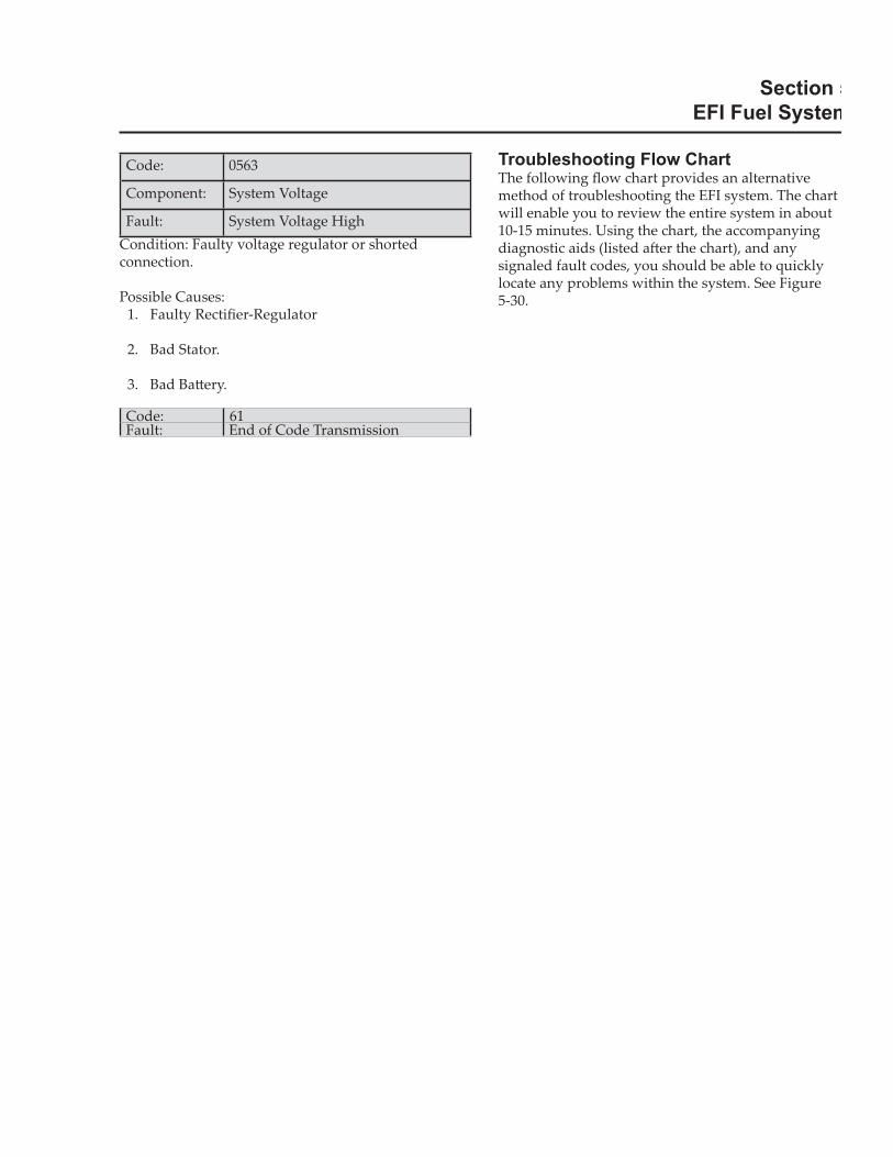
Code: 0563
Component: System Voltage
Fault: System Voltage HighCondition: Faulty voltage regulator or shorted connection.
Possible Causes: 1. Faulty Recti� er-Regulator
2. Bad Stator.
3. Bad Ba� ery.
Code: 61Fault: End of Code Transmission
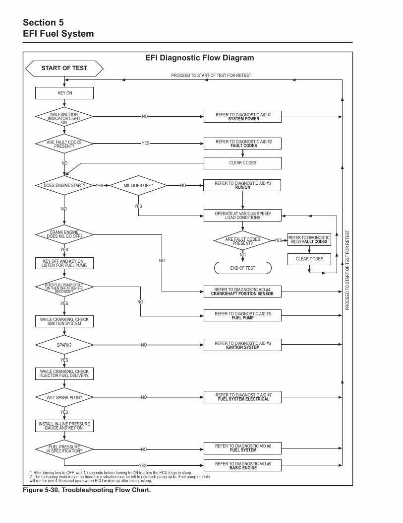
Troubleshooting Flow ChartThe following � ow chart provides an alternative method of troubleshooting the EFI system. The chart will enable you to review the entire system in about 10-15 minutes. Using the chart, the accompanying diagnostic aids (listed a� er the chart), and any signaled fault codes, you should be able to quickly locate any problems within the system. See Figure 5-30.
Section 5EFI Fuel System
EFI Diagnostic Flow Diagram
Figure 5-30. Troubleshooting Flow Chart.
START OF TEST
KEY ON
MALFUNCTIONINDICATOR LIGHT
ON
ARE FAULT CODES PRESENT?
NO
DOES ENGINE START?
NO
CRANK ENGINE. DOES MIL GO OFF?
YES
KEY OFF AND KEY ON1.LISTEN FOR FUEL PUMP.
DOES FUEL PUMP CYCLE ON THEN OFF AFTER 1–2
SECONDS2?
YES
WHILE CRANKING, CHECK IGNITION SYSTEM
SPARK?
YES
WHILE CRANKING, CHECK INJECTOR FUEL DELIVERY.
WET SPARK PLUG?
YES
INSTALL IN-LINE PRESSURE GAUGE AND KEY ON.
FUEL PRESSURE IN SPECIFICATION?
NO
YES
YES MIL GOES OFF?
YES
NO
NO
NO
NO
NO
YES
REFER TO DIAGNOSTIC AID #1 SYSTEM POWER
REFER TO DIAGNOSTIC AID #2 FAULT CODES
CLEAR CODES
NO REFER TO DIAGNOSTIC AID #3 RUN/ON
OPERATE AT VARIOUS SPEED/LOAD CONDITIONS
ARE FAULT CODES PRESENT?
NO
END OF TEST
REFER TO DIAGNOSTIC AID #4 CRANKSHAFT POSITION SENSOR
REFER TO DIAGNOSTIC AID #5 FUEL PUMP
REFER TO DIAGNOSTIC AID #6 IGNITION SYSTEM
REFER TO DIAGNOSTIC AID #7 FUEL SYSTEM ELECTRICAL
REFER TO DIAGNOSTIC AID #8 FUEL SYSTEM
REFER TO DIAGNOSTIC AID #9 BASIC ENGINE
YES REFER TO DIAGNOSTIC AID #2 FAULT CODES
CLEAR CODES
PROC
EED
TO S
TART
OF
TEST
FOR
RET
EST
PROCEED TO START OF TEST FOR RETEST
1. After turning key to OFF, wait 10 seconds before turning to ON to allow the ECU to go to sleep.2. The fuel pump module can be heard or a vibration can be felt to establish pump cycle. Fuel pump module will run for one 4-6 second cycle when ECU wakes up after being asleep.
Section 5EFI Fuel System
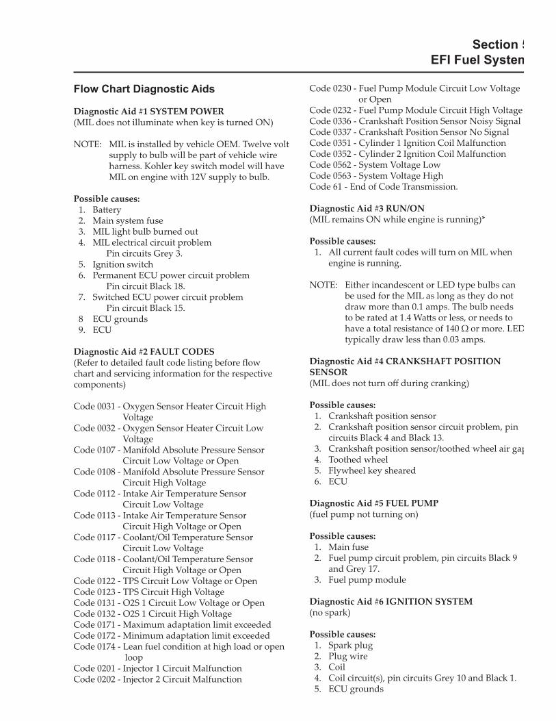
Flow Chart Diagnostic Aids
Diagnostic Aid #1 SYSTEM POWER(MIL does not illuminate when key is turned ON)
NOTE: MIL is installed by vehicle OEM. Twelve volt supply to bulb will be part of vehicle wire harness. Kohler key switch model will have MIL on engine with 12V supply to bulb.
Possible causes: 1. Ba� ery 2. Main system fuse 3. MIL light bulb burned out 4. MIL electrical circuit problem Pin circuits Grey 3. 5. Ignition switch 6. Permanent ECU power circuit problem Pin circuit Black 18. 7. Switched ECU power circuit problem Pin circuit Black 15. 8 ECU grounds 9. ECU
Diagnostic Aid #2 FAULT CODES(Refer to detailed fault code listing before � ow chart and servicing information for the respective components)
Code 0031 - Oxygen Sensor Heater Circuit High Voltage
Code 0032 - Oxygen Sensor Heater Circuit Low Voltage
Code 0107 - Manifold Absolute Pressure Sensor Circuit Low Voltage or Open
Code 0108 - Manifold Absolute Pressure Sensor Circuit High Voltage
Code 0112 - Intake Air Temperature Sensor Circuit Low Voltage
Code 0113 - Intake Air Temperature Sensor Circuit High Voltage or Open
Code 0117 - Coolant/Oil Temperature Sensor Circuit Low Voltage
Code 0118 - Coolant/Oil Temperature Sensor Circuit High Voltage or Open
Code 0122 - TPS Circuit Low Voltage or OpenCode 0123 - TPS Circuit High VoltageCode 0131 - O2S 1 Circuit Low Voltage or OpenCode 0132 - O2S 1 Circuit High VoltageCode 0171 - Maximum adaptation limit exceededCode 0172 - Minimum adaptation limit exceededCode 0174 - Lean fuel condition at high load or open
loopCode 0201 - Injector 1 Circuit MalfunctionCode 0202 - Injector 2 Circuit Malfunction
Code 0230 - Fuel Pump Module Circuit Low Voltage or Open
Code 0232 - Fuel Pump Module Circuit High VoltageCode 0336 - Cranksha� Position Sensor Noisy SignalCode 0337 - Cranksha� Position Sensor No SignalCode 0351 - Cylinder 1 Ignition Coil MalfunctionCode 0352 - Cylinder 2 Ignition Coil MalfunctionCode 0562 - System Voltage LowCode 0563 - System Voltage HighCode 61 - End of Code Transmission.
Diagnostic Aid #3 RUN/ON(MIL remains ON while engine is running)*
Possible causes: 1. All current fault codes will turn on MIL when
engine is running.
NOTE: Either incandescent or LED type bulbs can be used for the MIL as long as they do not draw more than 0.1 amps. The bulb needs to be rated at 1.4 Wa� s or less, or needs to have a total resistance of 140 � or more. LEDtypically draw less than 0.03 amps.
Diagnostic Aid #4 CRANKSHAFT POSITION SENSOR(MIL does not turn o� during cranking)
Possible causes: 1. Cranksha� position sensor 2. Cranksha� position sensor circuit problem, pin
circuits Black 4 and Black 13. 3. Cranksha� position sensor/toothed wheel air gap 4. Toothed wheel 5. Flywheel key sheared 6. ECU
Diagnostic Aid #5 FUEL PUMP(fuel pump not turning on)
Possible causes: 1. Main fuse 2. Fuel pump circuit problem, pin circuits Black 9
and Grey 17. 3. Fuel pump module
Diagnostic Aid #6 IGNITION SYSTEM(no spark)
Possible causes: 1. Spark plug 2. Plug wire 3. Coil 4. Coil circuit(s), pin circuits Grey 10 and Black 1. 5. ECU grounds
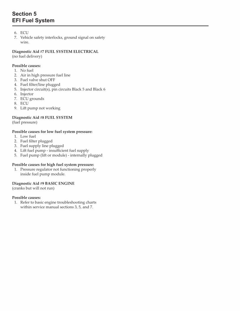
Section 5EFI Fuel System
6. ECU 7. Vehicle safety interlocks, ground signal on safety
wire.
Diagnostic Aid #7 FUEL SYSTEM ELECTRICAL(no fuel delivery)
Possible causes: 1. No fuel 2. Air in high pressure fuel line 3. Fuel valve shut OFF 4. Fuel � lter/line plugged 5. Injector circuit(s), pin circuits Black 5 and Black 6 6. Injector 7. ECU grounds 8. ECU 9. Li� pump not working
Diagnostic Aid #8 FUEL SYSTEM(fuel pressure)
Possible causes for low fuel system pressure: 1. Low fuel 2. Fuel � lter plugged 3. Fuel supply line plugged 4. Li� fuel pump - insu� cient fuel supply 5. Fuel pump (li� or module) - internally plugged
Possible causes for high fuel system pressure: 1. Pressure regulator not functioning properly
inside fuel pump module.
Diagnostic Aid #9 BASIC ENGINE(cranks but will not run)
Possible causes: 1. Refer to basic engine troubleshooting charts
within service manual sections 3, 5, and 7.
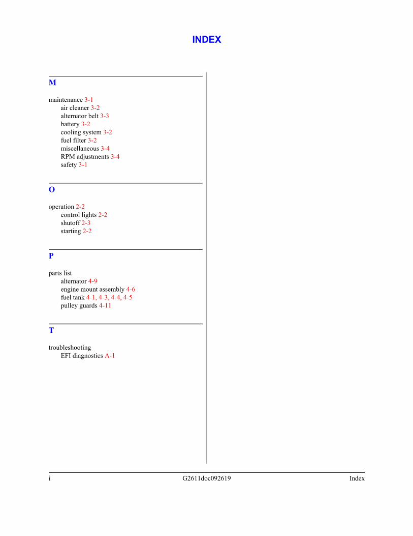
i G2611doc092619 Index
M
maintenance 3-1air cleaner 3-2alternator belt 3-3battery 3-2cooling system 3-2fuel filter 3-2miscellaneous 3-4RPM adjustments 3-4safety 3-1
O
operation 2-2control lights 2-2shutoff 2-3starting 2-2
P
parts listalternator 4-9engine mount assembly 4-6fuel tank 4-1, 4-3, 4-4, 4-5pulley guards 4-11
T
troubleshootingEFI diagnostics A-1
INDEX
Related Documents