DENSO ENGINE MANAGEMENT General 253 DENSO ENGINE MANAGEMENT General The V8 4.2 Liter supercharged engine is controlled by an ECM manufactured by DENSO. The Engine Management System (EMS) controls the following: • Engine fueling • Ignition timing • Closed loop fueling • Knock control • Idle speed control • Emission control • OBD • Interface with the immobilization system • Speed control The ECM controls the engine fueling by providing sequential fuel injection to all cylinders. Ignition is controlled by a direct ignition system, provided by eight plug top coils. The ECM is able to detect and correct for ignition knock on each cylinder and adjust the ignition timing for each cylinder to achieve optimum performance. The ECM uses a torque-based strategy to generate the torque required by the driver and other vehicle control modules. The EMS uses various sensors to determine the torque required from the engine. The EMS also interfaces with other vehicle electronic control modules's, via the CAN bus, to obtain additional information (e.g. road speed from the ABS control module). The EMS processes these signals and decides how much torque to generate. Torque is then generated by using various actuators to supply air, fuel and spark to the engine (electronic throttle, injectors, coils, etc.).

Welcome message from author
This document is posted to help you gain knowledge. Please leave a comment to let me know what you think about it! Share it to your friends and learn new things together.
Transcript

DENSO ENGINE MANAGEMENT
DENSO ENGINE MANAGEMENT
GeneralThe V8 4.2 Liter supercharged engine is controlled by an ECM manufactured by DENSO. The Engine Management System (EMS) controls the following:
• Engine fueling• Ignition timing• Closed loop fueling• Knock control• Idle speed control• Emission control• OBD• Interface with the immobilization system• Speed control
The ECM controls the engine fueling by providing sequential fuel injection to all cylinders. Ignition is controlled by a direct ignition system, provided by eight plug top coils. The ECM is able to detect and correct for ignition knock on each cylinder and adjust the ignition timing for each cylinder to achieve optimum performance.
The ECM uses a torque-based strategy to generate the torque required by the driver and other vehicle control modules. The EMS uses various sensors to determine the torque required from the engine. The EMS also interfaces with other vehicle electronic control modules's, via the CAN bus, to obtain additional information (e.g. road speed from the ABS control module). The EMS processes these signals and decides how much torque to generate. Torque is then generated by using various actuators to supply air, fuel and spark to the engine (electronic throttle, injectors, coils, etc.).
General 253

DENSO ENGINE MANAGEMENT
4.2 Liter Electronic Engine ControlsNOTE: Component Location (Sheet 1of 2)
1 PCV valve 7 MAPT sensor 13 CKP sensor
2 Fuel rail temperature sensor 8 CMP sensor 14 Spark plugs
3 Electric throttle 9 MAP sensor 15 Ignition coils
4 RFI capacitor 10 Universal Heated Exhaust Gas Oxygen (UHEGO) sensors
16 MAF/IAT
5 Injectors 11 CMP sensor
6 Knock sensor 12 Heated Exhaust Gas Oxygen (HEGO) sensors
254

DENSO ENGINE MANAGEMENT
4.2 Liter Electronic Engine ControlsNOTE: Component Location (Sheet 2 of 2)
1 Main relay 3 ECM 5 Brake light switch
2 Transfer box control module 4 APP 6 ABS control module
General 255

DENSO ENGINE MANAGEMENT
Engine Control Module (ECM)
The ECMis located in the E-Box in the plenum area on the passenger side of the engine compartment attached to the bulkhead.
System ECM has the following inputs:
• RCM• Park/neutral switch• Ignition coil feedback x2• Fuel rail temperature• Fuel rail pressure• Supercharger inlet pressure• Mass air flow• Engine speed• Camshaft position x2• Driver demand• Brake pedal position switch• Speed control switches• Generator load• Oxygen sensors pre catalyst x2• Oxygen sensors post catalyst x2• Throttle position• Cooling fan speed• Ignition switch position• Knock sensors x2• MAP• Intercooler temperature• Coolant temperature• Engine oil temperature
The ECM outputs to the following:
• Throttle Actuator• Brake vacuum pump relay• Ignition coils (x8)• Oxygen sensor heaters (4)• Fuel injectors (8)• Purge Valve• Engine Cooling Fan• Fuel pump relay• Starter Relay• EMS Main Relay• Viscous Fan Control• Generator Control• Diagnostic Module Tank Leakage (DMTL)
(NAS Only)• E box fan• FPDM
256

DENSO ENGINE MANAGEMENT
4.2 Liter Electronic Engine Controls-Input Control Diagram (Sheet 1 of 2)NOTE: Voltage sensor inputs
1 Main relay 8 Engine oil temperature sensor 15 Fuel rail pressure sensor
2 CMP sensor x2 9 MAF/IAT sensor 16 ECM
3 CKP sensor 10 Fuel rail temperature sensor 17 Fuse 27E
4 ECT sensor 11 RCM 18 Fuse 13E
5 APP sensor 12 Brake light switch 19 Ignition switch
6 MAPT sensor 13 Park/ neutral signal from TCM 20 Fuse 10E
7 MAP sensor 14 Knock sensors
Engine Control Module (ECM) 257

DENSO ENGINE MANAGEMENT
4.2 Liter Electronic Engine Controls-Control Diagram (Sheet 2 of 2)NOTE: A= Hardwired D= CAN
1 Injectors 10 Adaptive speed control sensor 19 Generator
2 Engine cooling fan control/moni-tor
11 Adaptive speed control module 20 ECM
3 ABS control module 12 Transfer box control module 21 Fuel pump relay
4 Steering angle sensor 13 Electric park brake control mod-ule
22 FPDM
5 Terrain response control module 14 ATC control module 23 Speed control switches
6 Instrument cluster 15 DMTL pump 24 Clock spring
7 TCM 16 UHEGOs 25 Electric throttle
8 RCM 17 Ignition coils
9 Differential control module 18 HEGOs
258
DENSO ENGINE MANAGEMENT
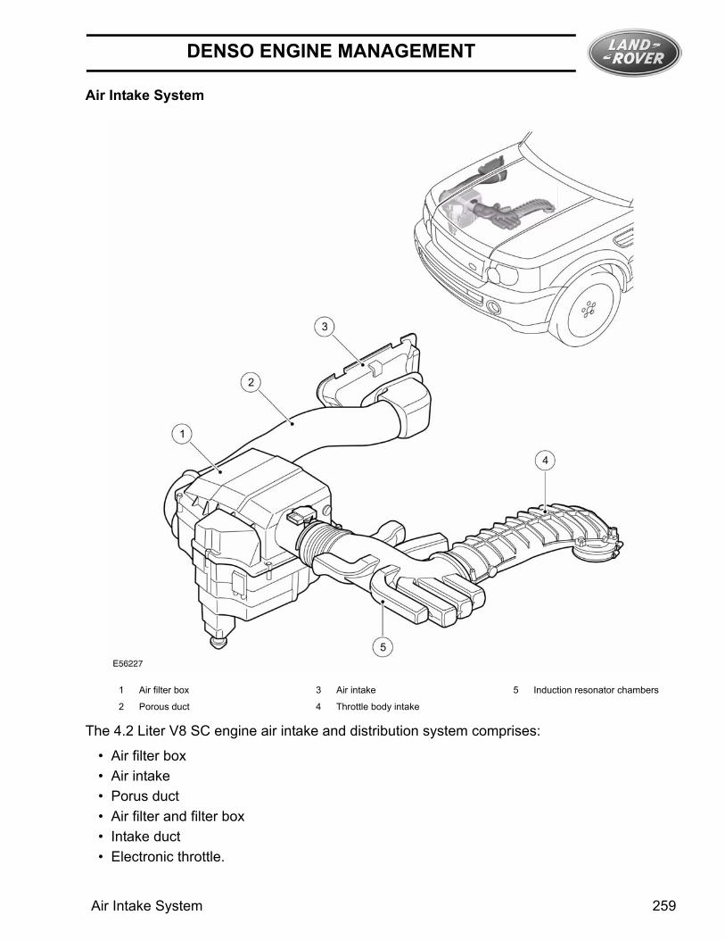
Air Intake System
The 4.2 Liter V8 SC engine air intake and distribution system comprises:
• Air filter box• Air intake• Porus duct• Air filter and filter box• Intake duct• Electronic throttle.
1 Air filter box 3 Air intake 5 Induction resonator chambers
2 Porous duct 4 Throttle body intake
Air Intake System 259

DENSO ENGINE MANAGEMENT
Air Filter BoxThe air filter box is located in the front of the engine bay on the inside of the RH front wing. Air is drawn from the air intake in the wing through a porous duct and into the air filter box. The filter box contains a paper air filter element.
Air Intake DuctThe air intake duct runs from the throttle body to the air filter box. The duct comprises two separate pieces. One piece runs from the air filter box to the front of the engine and the other from the front of the engine to the rear of the engine locating on the throttle body. The front half is manufactured from plastic and incorporates a number of resonator chambers. The rear part of the duct is manufactured from cast aluminum.
Component Locations
1 Induction elbow 5 LH intercooler 9 RH fuel rail
2 Charge air ducts 6 Fuel rail adapter 10 RH intercooler
3 Electronic throttle body 7 LH fuel rail
4 Injectors (8 of) 8 Supercharger
260

DENSO ENGINE MANAGEMENT
Electronic Throttle
The V8 EMS incorporates an electric throttle control system. The electronic throttle body is located on the air intake manifold in the engine compartment. The system comprises three main components:
• Electronic throttle control valve• APP• ECM
When the accelerator pedal is depressed the APP sensor provides a change in the monitored signals. The ECM compares this against an electronic “map” and moves the electronic throttle valve via a PWM control signal which is in proportion to the APP angle signal. The system is required to:
• Regulate the calculated intake air load based on the accelerator pedal sensor input signals and programmed mapping.
• Monitor the drivers input request for cruise control operation.• Automatically position the electronic throttle for accurate cruise control.• Perform all dynamic stability control throttle control interventions.• Monitor and carry out maximum engine and road speed cut out.• Provide differing responses for differing Terrain response modes.
A software strategy within the ECM enables the throttle position to be calibrated each ignition cycle. When the ignition is turned ON, the ECM performs a self test and calibration routine on the electronic throttle by closing the throttle full, then opening again. This tests the default position springs.
Electronic Throttle Pin Out Table
Pin No Description Pin No Description
1 Motor + 4 Sensor 2 signal
2 Motor - 5 5 volt supply
3 Sensor ground 6 Sensor 1 signal
Electronic Throttle 261

DENSO ENGINE MANAGEMENT
Mass Air Flow/Inlet Air Temperature SENSOR (MAF/AT)
The MAF/IATis located in the clean air duct immediately after the air filter box.
The air mass flow is determined by the cooling effect of inlet air passing over a “hot film” element contained within the device. The higher the air flow the greater the cooling effect and the lower the electrical resistance of the “hot film” element. The ECM then uses this signal from the MAF to calculate the air mass flowing into the engine.
The measured air mass flow is used in determining the fuel quantity to be injected in order to maintain the stichometric air/fuel mixture required for correct operation of the engine and exhaust catalysts. Should the device fail there is a software backup strategy that will be evoked once a fault has been diagnosed.
The following symptoms may be observed if the sensor fails:
• During driving the engine RPM might dip, before recovering.• Difficulty in starting or start - stall.• Poor throttle response / engine performance.• Lambda control and idle speed control halted.• Emissions incorrect.• AFM signal offset
The IAT sensor is integrated into the MAF meter. It is a temperature dependent resistor (thermistor), i.e. the resistance of the sensor varies with temperature. This thermistor is a NTC type element meaning that the sensor resistance decreases as the sensor temperature increases. The sensor forms part of a voltage divider chain with an additional resistor in the ECM. The voltage from this sensor changes as the sensor resistance changes, thus relating the air temperature to the voltage measured by the ECM.
The ECM stores a 25 Degrees Celsius (77° F) default value for air temperature in the event of a sensor failure.
262

DENSO ENGINE MANAGEMENT
Manifold Absolute Pressure Sensor (MAP)- Supercharger Inlet Pressure
The MAP sensor provides a voltage proportional to the absolute pressure in the supercharger intake. This signal allows the load on the engine to be calculated and used within the internal calculations of the ECM. The sensor is located below the electric throttle on the induction elbow.
MAP Pin Out Table
The output signal from the MAP sensor, together with the CKP and IAT sensors, is used by the ECM to calculate the amount of air induced into the cylinders. This enables the ECM to determine ignition timing and fuel injection duration values.
The MAP sensor receives a 5V supply voltage from pin 48 of ECM connector C0634 and provides an analogue signal to pin 38 of ECM connector C0634, which relates to the absolute manifold pressure and allows the ECM to calculate engine load. The ECM provides a ground for the sensor via pin 11 of ECM connector C0634.
If the MAP signal is missing, the ECM will substitute a default manifold pressure reading based on crankshaft speed and throttle angle. The engine will continue to run with reduced drivability and increased emissions, although this may not be immediately apparent to the driver. The ECM will store fault codes which can be retrieved using T4.
Pin No Description
1 MAPsignal
2 Sensor supply
3 Not used
4 Sensor ground
Manifold Absolute Pressure Sensor (MAP)- Supercharger Inlet Pressure 263

DENSO ENGINE MANAGEMENT
Manifold Absolute Pressure And Temperature Sensor (TMAP)
The MAPT is located to the rear of the RH engine bank intercooler outlet. The sensor measures the pressure and temperature of the inducted air prior to it entering the cylinders.
The sensor fits and seals using a radial ‘O’ ring seal directly to the inlet manifold.
The MAPT signal is used to retard the ignition timing relative to boost pressure. The intercooler temperature is used for air charge density calculations and for intercooler diagnostic purposes.
Pin No Description Input/Output
1 Boost pressure Output
2 Sensor supply Input
3 Intercooler out-let temperature
Output
4 Sensor ground -
264

DENSO ENGINE MANAGEMENT
Crankshaft Position Sensor (CKP)
The crankshaft position sensor is mounted at the rear underside of the engine near the transmission bell housing. Connection between the sensor and the harness is via a link harness and a two-way connector. Both wires go directly to the ECM. The sensor produces the signal which enables the ECM to determine the angle of the crankshaft, and the engine rpm. From this, the point of ignition, fuel injection, etc. is calculated. If the signal wires are reversed a 3 degrees advance in timing will occur, as the electronics within the ECM uses the falling edge of the signal waveform as its reference / timing point for each tooth.
The reluctor is pressed into the flywheel and has a "tooth" pattern based on 36 teeth at 10° intervals and approximately 5° wide: one of the teeth is removed to provide a hardware reference mark which is 30 degrees BTDC No.1 cylinder. Because of the crankshaft sensor's orientation, the target wheel uses windows stamped into the face, rather than actual teeth.
The sensor operates by generating an output voltage caused by the change in magnetic field that occurs as the windows pass in front of the sensor. The output voltage varies with the speed of the windows passing the sensor, the higher the engine speed, the higher the output voltage. Note that the output is also dependent on the air gap between the sensor and the teeth (the larger the gap, the weaker the signal, the lower the output voltage). The ECM transmits the engine speed to other vehicle control modules on CAN.
Crankshaft Position Sensor (CKP) 265

DENSO ENGINE MANAGEMENT
Camshaft Position Sensor (CMP)
Two sensors are located at the rear of the engine, in the cylinder head (one per bank), above the rear cylinders. The sensors are Variable Reluctor Sensor (VRS) type, producing four pulses for every two engine crankshaft revolutions. The sensing element is positioned between 0 and 2mm from the side of the cam gear wheel.
The camshaft timing wheel is a sintered component which has four teeth on it to enable the EMS to detect cylinder identification. The signal is used for:
• Cylinder recognition• Enabling sequential fuel injection• Knock control• Cylinder identification for diagnostic purposes.
Failure symptoms include:
• Ignition timing reverting to the base mapping, with no cylinder correction.• Active knock control is disabled, along with its diagnostic (Safe ignition map - loss of perfor-
mance).• Quick cam/crank synchronisation on start disabled.
266

DENSO ENGINE MANAGEMENT
Engine Coolant Temperature Sensor (ECT)
The ECT sensor is located at the front of the engine at the rear of the thermostat housing. The ECT sensor is a thermistor used to monitor the engine coolant temperature. The engine coolant temperature sensor is vital to the correct running of the engine as a richer mixture is required at lower block temperatures for good quality starts and smooth running, leaning off as the temperature rises to maintain emissions and performance.
The sensor has an operating temperature range of -30 Degrees Celsius to 125 Degrees Celsius (-22° F to 257° F). The maximum engine coolant temperature the ECM outputs on the CAN is the 119 Degrees Celsius (246° F). When a defective coolant sensor is detected, the ECM uses the oil temperature sensor value.
Engine Oil Temperature Sensor
Oil temperature is monitored through a temperature sensor mounted in the oil system. This component is a NTC. The sensor is mounted next to the oil pressure sensor at the front of the engine and locates into the oil filter bracket.
Engine Coolant Temperature Sensor (ECT) 267

DENSO ENGINE MANAGEMENT
Knock Sensors
The V8 EMS has two knock sensors located in the V of the engine, one per cylinder bank. The sensors are connected to the ECM via a twisted pair.
The knock sensors produce a voltage signal in proportion to the amount of mechanical vibration generated at each ignition point. Each sensor monitors the related cylinder bank.
The knock sensors incorporate a piezo-ceramic crystal. This crystal produces a voltage whenever an outside force tries to deflect it, (i.e. exerts a mechanical load on it). When the engine is running, the compression waves in the material of the cylinder block, caused by the combustion of the fuel/air mixture within the cylinders, deflect the crystal and produce an output voltage signal. The signals are supplied to the ECM, which compares them with `mapped' signals stored in memory. From this, the ECM can determine when detonation occurs on individual cylinders. When detonation is detected, the ECM retards the ignition timing on that cylinder for a number of engine cycles, then gradually returns it to the original setting.
Care must be taken at all times to avoid damaging the knock sensors, but particularly during removal and fitting procedures. The recommendations regarding torque and surface preparation must be adhered to. The torque applied to the sensor and the quality of the surface preparation both have an influence over the transfer of mechanical noise from the cylinder block to the crystal.
The ECM uses the signals supplied by the knock sensors, in conjunction with the signal it receives from the camshaft sensor, to determine the optimum ignition point for each cylinder. The ignition point is set according to preprogrammed ignition maps stored within the ECM. The ECM is programmed to use ignition maps for 98 RON premium specification fuel. It will also function on 91 RON regular specification fuel and learn new adaptions. If the only fuel available is of poor quality, or the customer switches to a lower grade of fuel after using a high grade for a period of time, the engine may suffer slight pre-ignition for a short period. This amount of pre-ignition will not damage the engine. This situation will be evident while the ECM learns and then modifies its internal mapping to compensate for the variation in fuel quality. This feature is called adaption. The ECM has the capability of adapting its fuel and ignition control outputs in response to several sensor inputs.
The ECM will cancel closed loop control of the ignition system if the signal received from either knock sensor becomes implausible. In these circumstances the ECM will default to a safe ignition map. This measure ensures the engine will not become damaged if low quality fuel is used. The MIL will not illuminate, although the driver may notice that the engine 'pinks' in some driving conditions and displays a drop in performance and smoothness.
268

DENSO ENGINE MANAGEMENT
When a knock sensor fault is stored, the ECM will also store details of the engine speed, engine load and the coolant temperature.
Accelerator Pedal Position Sensor (APP)
The APP sensors are located on the accelerator pedal assembly.
The APP sensors are used to determine the driver's request for vehicle speed, acceleration and deceleration. This value is used by the ECM and the throttle is opened to the correct angle by an electric motor integrated into the throttle body.
The APP Sensor signals are checked for range and plausibility. Two separate reference voltages are supplied to the pedal. Should one sensor fail, the other is used as a 'limp – home' input. In limp home mode due to an APP signal failure the ECM will limit the maximum engine speed to 2000 rpm.
APP Pin Out Table
Pin No Description
1 APP 1 ground
2 APP 1 demand
3 APP2 ground
4 Not used
5 APP 2 demand
6 Supply 2, 5 volt
7 Supply 1, 5 volt
8 Not used
Accelerator Pedal Position Sensor (APP) 269

DENSO ENGINE MANAGEMENT
Oxygen SensorsThere are four oxygen sensors located in the exhaust system. Two upstream before the catalytic converter and two down stream after the catalytic converter. The sensor monitors the level of oxygen in the exhaust gases and is used to control the fuel/air mixture. Positioning a sensor in the stream of exhaust gasses from each bank enables the ECM to control the fueling on each bank independently of the other, allowing much closer control of the air / fuel ratio and catalyst conversion efficiency.
Upstream Oxygen Sensors
Downstream Oxygen Sensors
The oxygen sensors need to operate at high temperatures in order to function correctly. To achieve the high temperatures required, the sensors are fitted with heater elements that are controlled by a PWM signal from the ECM. The heater elements are operated immediately following engine start and also during low load conditions when the temperature of the exhaust gases is insufficient to maintain the required sensor temperatures. A non-functioning heater delays the sensor’s readiness for closed loop control and influences emissions. The PWM duty cycle is carefully controlled to prevent thermal shock to cold sensors.
UHEGO (Universal Heated Exhaust Gas Oxygen) sensors also known as Linear or "Wide Band" sensors produces a constant voltage, with a variable current that is proportional to the oxygen content. This allows closed loop fueling control to a target lambda, i.e. during engine warm up (after the sensor has reached operating temperature and is ready for operation). This improves emission control.
270
DENSO ENGINE MANAGEMENT
The HEGO sensor uses Zirconium technology that produces an output voltage dependant upon the ratio of exhaust gas oxygen to the ambient oxygen. The device contains a Galvanic cell surrounded by a gas permeable ceramic, the voltage of which depends upon the level of O2 defusing through. Nominal output voltage of the device for l =1 is 300 to 500m volts. As the fuel mixture becomes richer (l<1) the voltage tends towards 900m volts and as it becomes leaner (l>1) the voltage tends towards 0 volts. Maximum tip temperature is 1,000 Degrees Celsius (1832° F) for a maximum of 100 hours.
Sensors age with mileage, increasing their response time to switch from rich to lean and lean to rich. This increase in response time influences the ECM closed loop control and leads to progressively increased emissions. Measuring the period of rich to lean and lean to rich switching monitors the response rate of the upstream sensors.
Diagnosis of electrical faults is continually monitored in both the upstream and downstream sensors. This is achieved by checking the signal against maximum and minimum threshold, for open and short circuit conditions.
Oxygen sensors must be treated with the utmost care before and during the fitting process. The sensors have ceramic material within them that can easily crack if dropped / banged or over-torqued. The sensors must be torqued to the required figure, (40-50Nm), with a calibrated torque wrench. Care should be taken not to contaminate the sensor tip when anti-seize compound is used on the thread. Heated sensor signal pins are tinned and universal are gold plated. Mixing up sensors could contaminate the connectors and affect system performance.
Failure Modes
• Mechanical fitting & integrity of the sensor.• Sensor open circuit / disconnected.• Short circuit to vehicle supply or ground.• Lambda ratio outside operating band.• Crossed sensors bank A & B.• Contamination from leaded fuel or other sources.• Change in sensor characteristic.• Harness damage.• Air leak into exhaust system.
Failure Symptoms
• Default to Open Loop fueling for the particular cylinder bank• High CO reading.• Strong smell of H02S (rotten eggs) till default condition.• Excess Emissions.
It is possible to fit front and rear sensors in their opposite location. However the harness connections are of different gender and color to ensure that the sensors cannot be incorrectly connected. In addition to this the upstream sensors have two holes in the shroud, whereas the down stream sensors have four holes in the shroud for the gas to pass through.
Oxygen Sensors 271

DENSO ENGINE MANAGEMENT
Ignition CoilsComponent Location
The V8 engine is fitted with eight plug-top coils that are driven directly by the ECM. This means that the ECM, at the point where sufficient charge has built up, switches the primary circuit of each coil and a spark is produced in the spark plug. The positive supply to the coil is fed from a common fuse. Each coil contains a power stage to trigger the primary current. The ECM sends a signal to each of the coils power stage to trigger the power stage switching. Each bank has a feedback signal that is connected to each power stage. If the coil power stage has a failure the feedback signal is not sent, causing the ECM to store a fault code appropriate to the failure.
The ECM calculates the dwell time depending on battery voltage and engine speed to ensure constant secondary energy. This ensures sufficient secondary (spark) energy is always available, without excessive primary current flow thus avoiding overheating or damage to the coils.
Power for the ignition coils is supplied from the main relay and a fuse in the BJB. A capacitor is connected in parallel with the power supplies to the ignition coils to suppress RFI (radio frequency interference).
The individual cylinder spark timing is calculated from a variety of inputs:
• Engine speed and load.• Engine temperature.• Knock control.• Auto gearbox shift control.• Idle speed control.
1 Ignition coil wth combined amplifi-er
2 Capacitor 3 Spark plug
272

DENSO ENGINE MANAGEMENT
Ignition System OverviewNOTE: A = Hardwired connections
1 Battery 7 Ignition coil and spark plug 5 13 Ignition coil and spark plug 7
2 Fusible link 11E, BJB 8 Ignition coil and spark plug 2 14 Ignition coil and spark plug 6
3 Ignition switch 9 Ignition coil and spark plug 3 15 Ignition coil and spark plug 1
4 Fuse 25P, ignition feed, CJB 10 Ignition coil and spark plug 8 16 Fuse 6E, BJB
5 Fuse 60P, crank feed, CJB 11 Capacitor 17 Main relay
6 ECM 12 Ignition coil and spark plug 4
Ignition Coils 273

DENSO ENGINE MANAGEMENT
Viscous Fan ControlThe ECM controls a viscous coupled fan to provide engine cooling. The ECM supplies the fan with a PWM signal that controls the amount of slippage of the fan, thus providing the correct amount of cooling fan speed and airflow. The EMS uses a Hall effect sensor to determine the fan speed.
Terrain Response™ Terrain Response ™ system allows the driver to select a program which will provide the optimum settings for traction and performance for prevailing terrain conditions.
As part of Terrain Response ™ there will be different throttle pedal progression maps associated with different Terrain Response ™ modes. The two extremes are likely to be a sand map (quick build up of torque with pedal travel) and grass/gravel/snow (very cautious build up of torque).
The V8 Super Charged implementation of throttle progression is based on a fixed blend time. The torque will blend from that on one map to that on the new map (for the same pedal position) over a fixed time. This means blending will always take the same amount of time but when the torque change is small the torque increase over time will be small, whilst if the torque change is greater then the torque increase over time will be steeper. The resulting acceleration of the vehicle will depend on the torque difference between the two maps as well as on the gear and range selected.
Generator
The Generator has a multifunction voltage regulator for use in a 14V charging system with 6÷12 zener diode bridge rectifiers.
The ECM monitors the load on the electrical system via PWM signal and adjusts the generator output to match the required load. The ECM also monitors the battery temperature to determine the generator regulator set point. This characteristic is necessary to protect the battery; at low temperatures battery charge acceptance is very poor so the voltage needs to be high to maximize any rechargeability, but at high temperatures the charge voltage must be restricted to prevent excessive gassing of the battery with consequent water loss.
274

DENSO ENGINE MANAGEMENT
The Generator has a smart charge capability that will reduce the electrical load on the Generator reducing torque requirements, this is implemented to utilize the engine torque for other purposes. This is achieved by monitoring three signals to the ECM:
• Generator sense (A sense), measures the battery voltage at the CJB.• Generator communication (Alt Com) communicates desired Generator voltage set point
from ECM to Generator.• Generator monitor (Alt Mon) communicates the extent of Generator current draw to ECM.
This signal also transmits faults to the ECM which will then sends a message to the instru-ment cluster on the CAN bus to illuminate the charge warning lamp.
Central Junction Box
The ECM is connected to ignition switch I and II. When the ignition is turned ON, 12V is applied to the ignition sense input. The ECM then starts its power up routines and turns ON the ECM main relay, the main power to the ECM and it's associated system components. When the ignition is turned OFF the ECM will maintain its powered up state for up to 20 minutes while it initiates its power down routine and on completion will turn OFF the ECM main relay. The ECM will normally power down in approximately 60 seconds, do not disconcert the battery until the ECM is completely powered down.
Fuel Tank and LinesThe major components of the 4.2L V8 supercharged fuel system comprise a fuel tank, a fuel pump, a fuel filler assembly and two fuel level sensors.
The 4.2L V8 supercharged fuel system uses an electronic returnless fuel system which comprises a pump module mounted in the fuel tank to deliver fuel at variable flow and pressure to the fuel rails which supply fuel to all fuel injectors. The fuel pump operation is regulated by a fuel pump driver module which is controlled by the engine management system. The control module regulates the flow and pressure supplied by controlling the operation of the fuel pump using a Pulse Width Modulation (PWM) output.
Central Junction Box 275

DENSO ENGINE MANAGEMENT
Fuel Delivery System Component LocationNOTE: 4.2L V8 Supercharged
1 Filler cap and lanyard 8 Mounting screw (6 off) 15 Tank breather pipe
2 Breather line 'Y' piece to charcoal canister
9 Cover 16 Fuel filler pipe
3 Charcoal canister purge line 10 Cradle 17 Charcoal canister vent pipe
4 Charcoal canister 11 Pipe - Fuel pump to engine (feed) 18 DMTL pump (NAS only)
5 Rear differential breather pipe 12 Pipe - EVAP purge valve to char-coal canister
19 DMTL filter (NAS only)
6 Tank breather pipe 13 Fuel tank
7 Heat shield 14 Fuel pump module assembly
276
DENSO ENGINE MANAGEMENT
Purge Valve
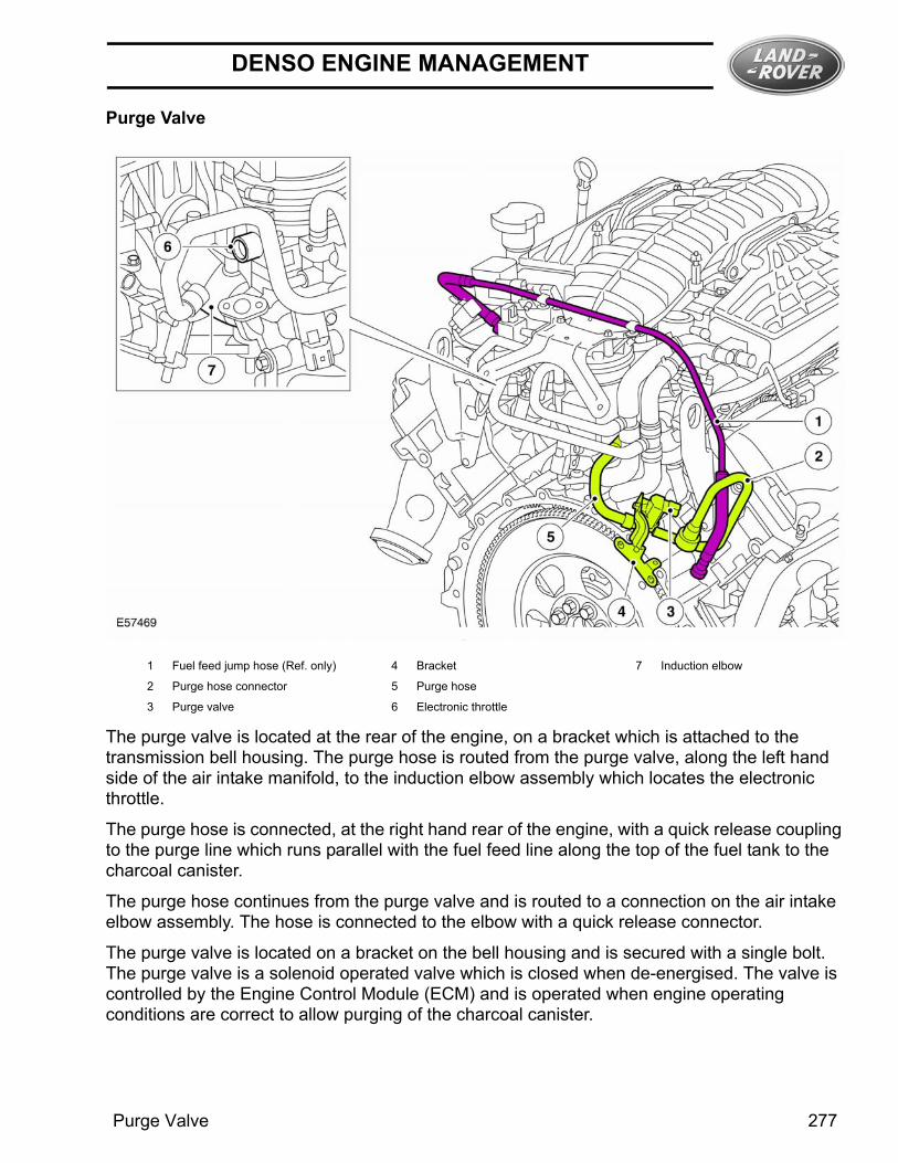
The purge valve is located at the rear of the engine, on a bracket which is attached to the transmission bell housing. The purge hose is routed from the purge valve, along the left hand side of the air intake manifold, to the induction elbow assembly which locates the electronic throttle.
The purge hose is connected, at the right hand rear of the engine, with a quick release coupling to the purge line which runs parallel with the fuel feed line along the top of the fuel tank to the charcoal canister.
The purge hose continues from the purge valve and is routed to a connection on the air intake elbow assembly. The hose is connected to the elbow with a quick release connector.
The purge valve is located on a bracket on the bell housing and is secured with a single bolt. The purge valve is a solenoid operated valve which is closed when de-energised. The valve is controlled by the Engine Control Module (ECM) and is operated when engine operating conditions are correct to allow purging of the charcoal canister.
1 Fuel feed jump hose (Ref. only) 4 Bracket 7 Induction elbow
2 Purge hose connector 5 Purge hose
3 Purge valve 6 Electronic throttle
Purge Valve 277

DENSO ENGINE MANAGEMENT
The ECM keeps the purge valve closed (de-energised) below a predetermined engine coolant temperature and engine speed to protect the engine tune and catalytic converter performance. If the purge valve is opened during cold running conditions or at engine idle speed, the additional fuel vapor can cause the engine to have erratic idle speed or even stall. When engine operating conditions are correct, the ECM opens the purge valve (energised) and the depression at the inlet manifold draws a fuel vapor and fresh air mix from the charcoal canister. When the purging process is active, fresh air is drawn into the charcoal canister via the DMTL pump atmospheric vent connection and its filter on NAS vehicles and via the atmospheric vent hose connection and the spider trap on non NAS vehicles.
On NAS vehicles the system does not include a pressure test point. Pressure testing of the purge valve hose is achieved by disconnecting the purge valve joint on the underside of the vehicle, forward of the fuel tank and connecting a special tool to allow the system to be pressure tested. The test performs a pressure test on the purge hose connection forward of the fuel tank back to the charcoal canister. The special tool is then connected to the purge hose connection forward of the fuel tank to perform a pressure test on the purge hose to the purge valve.
Fuel PumpThe submersible electric fuel pump is attached to a carrier and is located at the bottom of the swirl pot inside the fuel tank. The fuel pressure regulator, which controls the fuel pressure in the feed pipe to fuel rail, is located in the fuel manifold in the fuel tank.
Fuel Pump RelayThe ECM controls the fuel pump relay which in turn controls the power supply to the fuel pump driver module. The ECM energizes the relay ON with ignition ON, via pin A95 of the ECM.
278

DENSO ENGINE MANAGEMENT
Fuel Pump Driver Module
The fuel pump driver module is located in the rear LH quarter adjacent to the parking aid control module.
The fuel pump is control by the ECM. The ECM sends a PWM signal to the fuel pump driver module from pin B20 of the ECM, the frequency of the signal determines the duty cycle of the pump. the PWM signal to the pump represents half the ON time of the pump. If the ECM transmits a 50% on time the fuel pump driver module drives the pump at 100%. If the ECM transmits a 5% ON time the fuel pump driver module drives the pump at 10%. The fuel pump driver module will only turn the fuel pump ON if it receive a valid signal between 4% and 50%. When The ECM requires the fuel pump to be turned OFF the ECM transmits a duty cycle signal of 75%.
The status of the fuel pump driver module is monitored by the ECM on pin B21. Any errors can be retrieved from The ECM. The fuel pump driver module cannot be interrogated for diagnostic purposes.
The MAP controls The fuel pump driver module in response to inputs from the fuel rail pressure sensor, MAP and the MAF/IAT sensor.
The fuel pressure range is 0.9 - 5.4 bar (13 - 78 psi).
Harness Connector C2369 pin out details
Pin No Description Input/Output
1 Pump + Output
2 Pump - -
3 ECMPWM signal Input
4 Diagnostic signal Output
5 Battery voltage Input
6 GND -
Fuel Pump Driver Module 279

DENSO ENGINE MANAGEMENT
Fuel Rails
Four fuel injectors are installed in each intercooler adapter and are connected to the fuel rail. 'O' ring seals are used to seal the injectors in the fuel rails and the intercooler adapters.
A fuel pressure accumulator is attached to each of the fuel rails.
Fuel Rail Pressure SensorThe fuel rail pressure sensor is located on top of the fuel rail adjacent to the fuel inlet. The fuel rail pressure sensor measures the pressure of the fuel in the fuel rail. This input is then used by the ECM which commands the FPDM to control the amount of fuel delivered to the fuel rail.
1 RH fuel pressure accumulator 4 Fuel temperature sensor 7 LH fuel rail
2 Injectors (8 of) 5 Fuel pressure sensor 8 LH fuel pressure accumulator
3 RH fuel rail 6 Fuel supply 9 Fuel supply cross over pipe
280

DENSO ENGINE MANAGEMENT
Fuel Rail Temperature Sensor
The fuel rail temperature sensor measures the temperature of the fuel in the fuel rail. This input is then used to deliver the correct quantity of fuel to the engine. The sensors operating range is -40 Degrees Celsius to 150 Degrees Celsius (-40° F to 302° F). The fuel rail temperature sensor is fitted on the rear of the right hand bank (bank A) fuel rail.
Fuel Injectors
The engine has 8 fuel injectors (one per cylinder), each injector is directly driven by the ECM. The injectors are fed by a common fuel rail as part of a ‘return less’ fuel system. The fuel rail pressure is regulated to 4.5 bar by a fuel pressure regulator which is integral to the fuel pump module, within the fuel tank. The injectors can be checked by resistance checks. The ECM monitors the output power stages of the injector drivers for electrical faults.
The injectors have a resistance of 13.8 Ohms ± 0.7 Ohms @ 20 Degrees Celsius (68° F)
Fuel Rail Temperature Sensor 281

DENSO ENGINE MANAGEMENT
282

DENSO ENGINE MANAGEMENT
Denso ECM Pinouts
Connector C0634
PinNo
WireColor
Description Input/Output
1 Y Not used -
2 GB Not used -
3 WG Generator monitor Input
4 Not used -
5 Not used -
6 B CKP sensor - Input
7 R CMP sensor 1GND -
8 N CMP sensor 2GND -
9 Not used -
10 BG TP sensor GND -
11 BG MAP sensor ground -
12 GB FRP sensor ground -
13 Not used -
14 Not used Input
15 BG ECT ground -
16 Not usedMAF ground
-
17 Not used -
18 BP MAF sensor ground -
19 B Knock sensor 1A ground -
20 S Knock sensor 1B ground -
21 Not used -
22 Not used -
23 Y Oil temperature sensor Input
24 MAPT sensor 5v ref Output
25 Not used -
26 N UHEGO sensor bank Bsignal
Input
27 G UHEGO sensor bank BGND
-
28 R UHEGO sensor bank Asignal
Input
29 Y UHEGO sensor bank AGND
-
30 O CKP sensor + Input
31 Not used -
32 Not used -
33 G CMP signal bank B Input
34 Y CMP signal bank A Input
35 Not used -
36 Not used -
37 Not used -
38 MAPsignal Input
39 IAT Input
40 Not used Input
41 Not used Input
42 N Knock sensor 1 A + Input
43 G Knock sensor 1 B + Input
PinNo
WireColor
Description Input/Output
Denso ECM Pinouts 283

DENSO ENGINE MANAGEMENT
44 Not used -
45 Not used -
46 YR Fuel rail temperature sen-sor
Input
47 Fuel rail pressure sensor5 V ref voltage
Output
48 OY MAP sensor 5 V ref volt-age
Output
49 Not used -
50 YU Not used -
51 YR Not used -
52 YG Not used -
53 YU Not used -
54 YR Ignition coil cylinder 4B Output
55 GR Ignition coil cylinder 4A Output
56 GR Ignition coil cylinder 3B Output
57 YR Ignition coil cylinder 3A Output
58 GW Ignition coil cylinder 2B Output
59 Y Ignition coil cylinder 2A Output
60 GW Ignition coil cylinder 1B Output
61 GU Ignition coil cylinder 1A Output
62 GB Ignition failure signal bankA
Input
63 Y Viscous fan speed moni-tor
Input
64 YB Ignition failure signal bankB
Input
65 R TP sensor 1 Input
66 U MAF Input
67 Y TP sensor 2 Input
68 UY ECT Input
69 BP Inlet manifold boost pres-sure
Input
70 GW MAF Input
71 Fuel rail pressure sensorsignal
Input
PinNo
WireColor
Description Input/Output
72 OY Electric throttle 5V refer-ence
Output
73 Not used -
74 RW Throttle valve open direc-tion -
Output
75 GW Throttle valve open direc-tion +
Output
76 RU UHEGO Heater bank A Output
77 RW UHEGO Heater bank B Output
78 BG Injector cylinder 1A Output
79 BR Injector cylinder 1B Output
80 BP Injector cylinder 2A Output
81 BO Injector cylinder 2B Output
82 BG Injector cylinder 3A Output
83 U Injector cylinder 3B Output
84 BW Injector cylinder 4A Output
85 UY Injector cylinder 4B Output
86 Y Not used -
87 YU Not used -
88 Not used -
89 Not used -
90 Not used -
91 Not used -
92 UY Purge valve Output
93 B Viscous fan request Output
94 UB E box fan Output
95 YN FPDM power Output
96 WR Generator control Output
PinNo
WireColor
Description Input/Output
284

DENSO ENGINE MANAGEMENT
Connector C0635
PinNo
WireColor
Description Input/Output
1 B Signal ground 1 -
2 B Power ground 1 -
3 B Power ground 3 -
4 NO Power ground 2 -
5 B ECM power Output
6 RG Electric throttle power Input
7 YLG APP sensor ground 1 -
8 BG APP sensor ground 2 -
9 Not used -
10 Not used -
11 Not used -
12 Not used -
13 Not used -
14 Not used -
15 GO Park/ Neutral signal Input
16 NU EMS relay Output
17 WR Crank request Input
18 Not used -
19 OY APP sensor 2 5V ref Output
20 FPDM control Output
21 FPDM monitor Input
22 RB HEGO sensor A GND -
23 G DMTL heater Output
24 RB APP sensor 1 signal Output
25 U HEGO sensor A Input
26 WU HEGO sensor B Input
27 Not used -
28 YG RCM Input
29 Not used -
30 BO Ignition switch Input
31 Not used -
32 R APP sensor 1 5V refer-ence
Output
33 Y DMTL pump Output
34 RB HEGO sensor B GND -
35 R Speed control switch - Output
36 PU Speed control switch + Input
37 Not used -
38 U APP sensor 2 demand Input
39 Not used -
40 Not used -
41 GP Brake pedal switch Input
42 Not used -
43 Not used -
44 YB CAN out - Input/out-put
45 YB CAN in - Input/out-put
PinNo
WireColor
Description Input/Output
Denso ECM Pinouts 285

DENSO ENGINE MANAGEMENT
46 WO HEGO heater A Output
47 G HEGO heater B Output
48 R DMTL valve Output
49 Not used -
50 G Vacuum pump relay Output
51 UR Starter relay Output
52 Not used -
53 Not used -
54 NO Battery voltage Input
55 Not used -
56 Not used -
57 YN CAN out + Input/out-put
58 YN CAN in + Input/out-put
PinNo
WireColor
Description Input/Output
286
Related Documents