© 2017 Avco Corporation. All Rights Reserved. Engine Installation and Operation Manual IO-390-C Series January 2017 Part No. IOM-IO-390-C Series

Welcome message from author
This document is posted to help you gain knowledge. Please leave a comment to let me know what you think about it! Share it to your friends and learn new things together.
Transcript
© 2017 Avco Corporation. All Rights Reserved.
Engine Installation and Operation Manual
IO-390-C Series
January 2017
Part No. IOM-IO-390-C Series

IO-390-C Series Engine Installation and Operation Manual
Lycoming Part Number: IOM-IO-390-C Series
Contact Us:
Mailing Address:
Lycoming Engines 652 Oliver Street Williamsport, PA 17701 USA
Phone:
Factory
U.S. and Canada Toll Free:
Direct:
+1 (800) 258-3279
+1 (570) 323-6181
Technical Support Hotline
+1 (877) 839-7878 (Toll Free)
+1 (570) 327-7222
Lycoming’s regular business hours are Monday through Friday from 8:00AM through 5:00PM Eastern Time (-5 GMT).
Visit us Online: www.Lycoming.com
IO-390-C Series Engine Installation and Operation Manual
© 2017 Avco Corporation. All Rights Reserved Record of Revisions January 2017 Page i
RECORD OF REVISIONS
Revision
Revision
Date
Revised
By Revision Description
Original
Original Release of Installation and Operation Manual - Part No.
IOM-IO-390-C Series

IO-390-C Series Engine Installation and Operation Manual
Record of Revisions © 2017 Avco Corporation. All Rights Reserved Page ii January 2017
This page intentionally left blank.
IO-390-C Series Engine Installation and Operation Manual
© 2017 Avco Corporation. All Rights Reserved Service Document List January 2017 Page iii
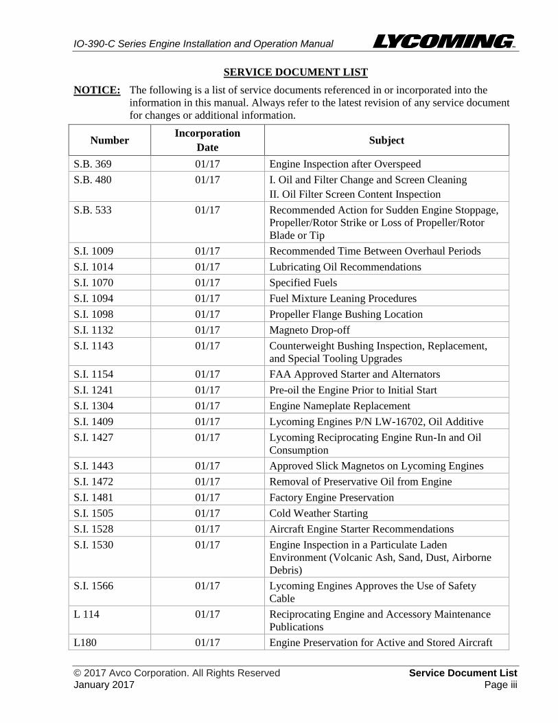
SERVICE DOCUMENT LIST
NOTICE: The following is a list of service documents referenced in or incorporated into the
information in this manual. Always refer to the latest revision of any service document
for changes or additional information.
Number Incorporation
Date Subject
S.B. 369 01/17 Engine Inspection after Overspeed
S.B. 480 01/17 I. Oil and Filter Change and Screen Cleaning
II. Oil Filter Screen Content Inspection
S.B. 533 01/17 Recommended Action for Sudden Engine Stoppage,
Propeller/Rotor Strike or Loss of Propeller/Rotor
Blade or Tip
S.I. 1009 01/17 Recommended Time Between Overhaul Periods
S.I. 1014 01/17 Lubricating Oil Recommendations
S.I. 1070 01/17 Specified Fuels
S.I. 1094 01/17 Fuel Mixture Leaning Procedures
S.I. 1098 01/17 Propeller Flange Bushing Location
S.I. 1132 01/17 Magneto Drop-off
S.I. 1143 01/17 Counterweight Bushing Inspection, Replacement,
and Special Tooling Upgrades
S.I. 1154 01/17 FAA Approved Starter and Alternators
S.I. 1241 01/17 Pre-oil the Engine Prior to Initial Start
S.I. 1304 01/17 Engine Nameplate Replacement
S.I. 1409 01/17 Lycoming Engines P/N LW-16702, Oil Additive
S.I. 1427 01/17 Lycoming Reciprocating Engine Run-In and Oil
Consumption
S.I. 1443 01/17 Approved Slick Magnetos on Lycoming Engines
S.I. 1472 01/17 Removal of Preservative Oil from Engine
S.I. 1481 01/17 Factory Engine Preservation
S.I. 1505 01/17 Cold Weather Starting
S.I. 1528 01/17 Aircraft Engine Starter Recommendations
S.I. 1530 01/17 Engine Inspection in a Particulate Laden
Environment (Volcanic Ash, Sand, Dust, Airborne
Debris)
S.I. 1566 01/17 Lycoming Engines Approves the Use of Safety
Cable
L 114 01/17 Reciprocating Engine and Accessory Maintenance
Publications
L180 01/17 Engine Preservation for Active and Stored Aircraft

IO-390-C Series Engine Installation and Operation Manual
Service Document List © 2017 Avco Corporation. All Rights Reserved Page iv January 2017
This page intentionally left blank.
IO-390-C Series Engine Installation and Operation Manual
© 2017 Avco Corporation. All Rights Reserved Table of Contents January 2017 Page v
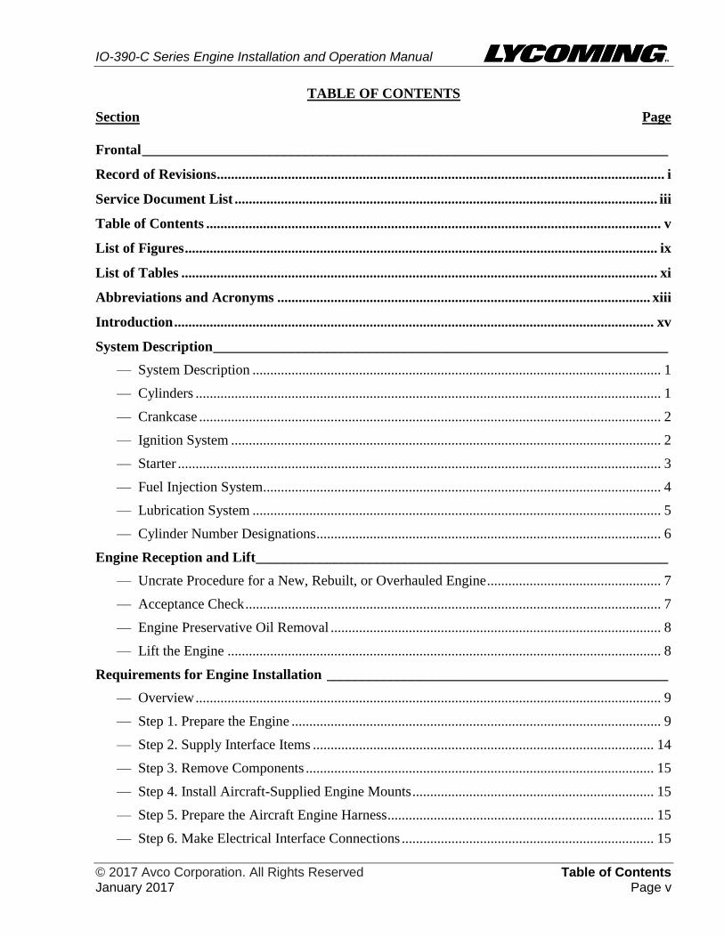
TABLE OF CONTENTS
Section Page
Frontal __________________________________________________________________________
Record of Revisions .............................................................................................................................. i
Service Document List ....................................................................................................................... iii
Table of Contents ................................................................................................................................ v
List of Figures ..................................................................................................................................... ix
List of Tables ...................................................................................................................................... xi
Abbreviations and Acronyms ......................................................................................................... xiii
Introduction ....................................................................................................................................... xv
System Description ________________________________________________________________
— System Description ................................................................................................................... 1
— Cylinders ................................................................................................................................... 1
— Crankcase .................................................................................................................................. 2
— Ignition System ......................................................................................................................... 2
— Starter ........................................................................................................................................ 3
— Fuel Injection System................................................................................................................ 4
— Lubrication System ................................................................................................................... 5
— Cylinder Number Designations ................................................................................................. 6
Engine Reception and Lift __________________________________________________________
— Uncrate Procedure for a New, Rebuilt, or Overhauled Engine ................................................. 7
— Acceptance Check ..................................................................................................................... 7
— Engine Preservative Oil Removal ............................................................................................. 8
— Lift the Engine .......................................................................................................................... 8
Requirements for Engine Installation ________________________________________________
— Overview ................................................................................................................................... 9
— Step 1. Prepare the Engine ........................................................................................................ 9
— Step 2. Supply Interface Items ................................................................................................ 14
— Step 3. Remove Components .................................................................................................. 15
— Step 4. Install Aircraft-Supplied Engine Mounts .................................................................... 15
— Step 5. Prepare the Aircraft Engine Harness ........................................................................... 15
— Step 6. Make Electrical Interface Connections ....................................................................... 15

IO-390-C Series Engine Installation and Operation Manual
Table of Contents © 2017 Avco Corporation. All Rights Reserved Page vi January 2017
Section Page
Engine Installation ________________________________________________________________
— Engine Installation Overview .................................................................................................. 17
— Step 1. Install the Engine on Mounts ...................................................................................... 18
— Step 2. Connect the Wiring Harness ....................................................................................... 18
— Step 3. Install External Accessories (as necessary) ................................................................ 18
— Step 4. Connect the Linkages .................................................................................................. 18
— Step 5. Install Baffling ............................................................................................................ 18
— Step 6. Install the Compressor Belt (as necessary) ................................................................. 18
— Step 7. Install the Propeller ..................................................................................................... 18
— Step 8. Connect Fuel Lines ..................................................................................................... 19
— Step 9. Connect Oil Lines ....................................................................................................... 20
— Step 10. Install Components That Had Been Removed Before Engine Installation
and Any Additional Ship Loose Components ........................................................... 20
— Step 11. Add Oil...................................................................................................................... 20
— Step 12. Engine Pre-Oil Procedure ......................................................................................... 21
— Step 13. Add Fuel.................................................................................................................... 22
— Step 14. Final Installation Inspection ...................................................................................... 22
— Step 15. Close Engine Compartment ...................................................................................... 22
— Engine Installation Checklist .................................................................................................. 23
Field Run-In _____________________________________________________________________
— Field Run-In Procedure ........................................................................................................... 25
Engine Initiation __________________________________________________________________
— Engine Initiation ...................................................................................................................... 27
— Warranty Requirement ............................................................................................................ 27
— Step 1. Pre-Flight Inspection for Engine Initiation ................................................................. 27
— Step 2. Engine Start ................................................................................................................. 29
— Step 3. Engine Run-Up ........................................................................................................... 31
— Step 4. Engine Stop ................................................................................................................. 32
— Step 5. Break-In/Flight Test/50-Hour Operation .................................................................... 33
— Step 6. Required Inspections During Break-In (50-Hour Operation) ..................................... 34

IO-390-C Series Engine Installation and Operation Manual
© 2017 Avco Corporation. All Rights Reserved Table of Contents January 2017 Page vii
Section Page
Engine Operation _________________________________________________________________
— Step 1. Pre-Flight Check ......................................................................................................... 35
— Step 2. Engine Start ................................................................................................................. 35
— Step 3. Engine Run-Up ........................................................................................................... 37
— Step 4. Engine Operation ........................................................................................................ 38
— Operation in Flight ............................................................................................................. 39
— Fuel Mixture Leaning......................................................................................................... 39
— Step 5. Engine Stop ................................................................................................................. 40
Engine Conditions ________________________________________________________________
— Action for Engine Conditions ................................................................................................. 41
—Apply Heat to a Cold Engine .............................................................................................. 42
—Cold Weather Engine Start ................................................................................................. 43
—Engine Operation in Hot Weather ....................................................................................... 44
—Volcanic Ash ....................................................................................................................... 44
—Overspeed............................................................................................................................ 44
—Low Oil Pressure During Flight .......................................................................................... 45
Engine Preservation and Storage ____________________________________________________
— Engine Corrosion and Prevention ........................................................................................... 47
— Engine Preservation Guidelines - 31 to 60 Days .................................................................... 48
— Fuel Injector Preservation ....................................................................................................... 50
Appendix ________________________________________________________________________
— Appendix A - Engine Specifications and Operating Limits ................................................... 51
— Appendix B - Installation Drawings ....................................................................................... 55
— Appendix C - Performance Data ............................................................................................. 57

IO-390-C Series Engine Installation and Operation Manual
Table of Contents © 2017 Avco Corporation. All Rights Reserved Page viii January 2017
This page intentionally left blank.
IO-390-C Series Engine Installation and Operation Manual
© 2017 Avco Corporation. All Rights Reserved List of Figures January 2017 Page ix
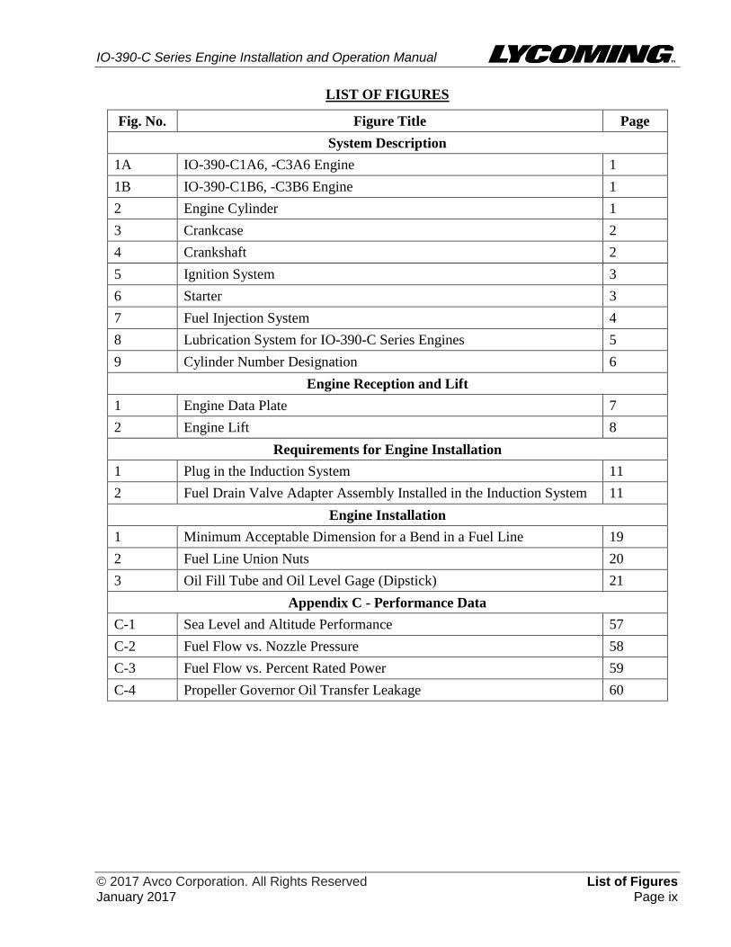
LIST OF FIGURES
Fig. No. Figure Title Page
System Description
1A IO-390-C1A6, -C3A6 Engine 1
1B IO-390-C1B6, -C3B6 Engine 1
2 Engine Cylinder 1
3 Crankcase 2
4 Crankshaft 2
5 Ignition System 3
6 Starter 3
7 Fuel Injection System 4
8 Lubrication System for IO-390-C Series Engines 5
9 Cylinder Number Designation 6
Engine Reception and Lift
1 Engine Data Plate 7
2 Engine Lift 8
Requirements for Engine Installation
1 Plug in the Induction System 11
2 Fuel Drain Valve Adapter Assembly Installed in the Induction System 11
Engine Installation
1 Minimum Acceptable Dimension for a Bend in a Fuel Line 19
2 Fuel Line Union Nuts 20
3 Oil Fill Tube and Oil Level Gage (Dipstick) 21
Appendix C - Performance Data
C-1 Sea Level and Altitude Performance 57
C-2 Fuel Flow vs. Nozzle Pressure 58
C-3 Fuel Flow vs. Percent Rated Power 59
C-4 Propeller Governor Oil Transfer Leakage 60

IO-390-C Series Engine Installation and Operation Manual
List of Figures © 2017 Avco Corporation. All Rights Reserved Page x January 2017
This page intentionally left blank.

IO-390-C Series Engine Installation and Operation Manual
© 2017 Avco Corporation. All Rights Reserved List of Tables January 2017 Page xi
LIST OF TABLES
Table
No. Table Title Page
Requirements for Engine Installation
1 Prerequisites for Engine Installation 9
2 Optional Equipment, Recommendations, and Requirements to Prepare
the Engine for Installation
14
Engine Installation
1 Aircraft Where IO-390-C Series Engines Can Be Installed 17
2 Aircraft Where IO-390-C Series Engines Cannot be Installed 17
3 Engine Installation Steps and References 17
Engine Initiation
1 Engine Initiation Procedures for All Lycoming Engines (Except Engine
Overhauled in the Field)
27
Engine Operation
1 Prerequisite Requirements for Engine Operation 35
Engine Conditions
1 Action for Engine Conditions 41
Appendix A - Engine Specifications and Operating Limits
A-1 IO-390-C Series Engine Specifications 51
A-2 Table of Operating Limits for IO-390-C Series Engines 53
A-3 Accessory Drives for IO-390-C1A6 & -C3A6 Engines 54
A-4 Accessory Drives for IO -390-C1B6 & -C3B6 Engines 54
Appendix B - Installation Drawings
B-1 Installation Drawings for IO-390-C Series Engines 55

IO-390-C Series Engine Installation and Operation Manual
List of Tables © 2017 Avco Corporation. All Rights Reserved Page xii January 2017
This page intentionally left blank.
IO-390-C Series Engine Installation and Operation Manual
© 2017 Avco Corporation. All Rights Reserved Abbreviations and Acronyms January 2017 Page xiii
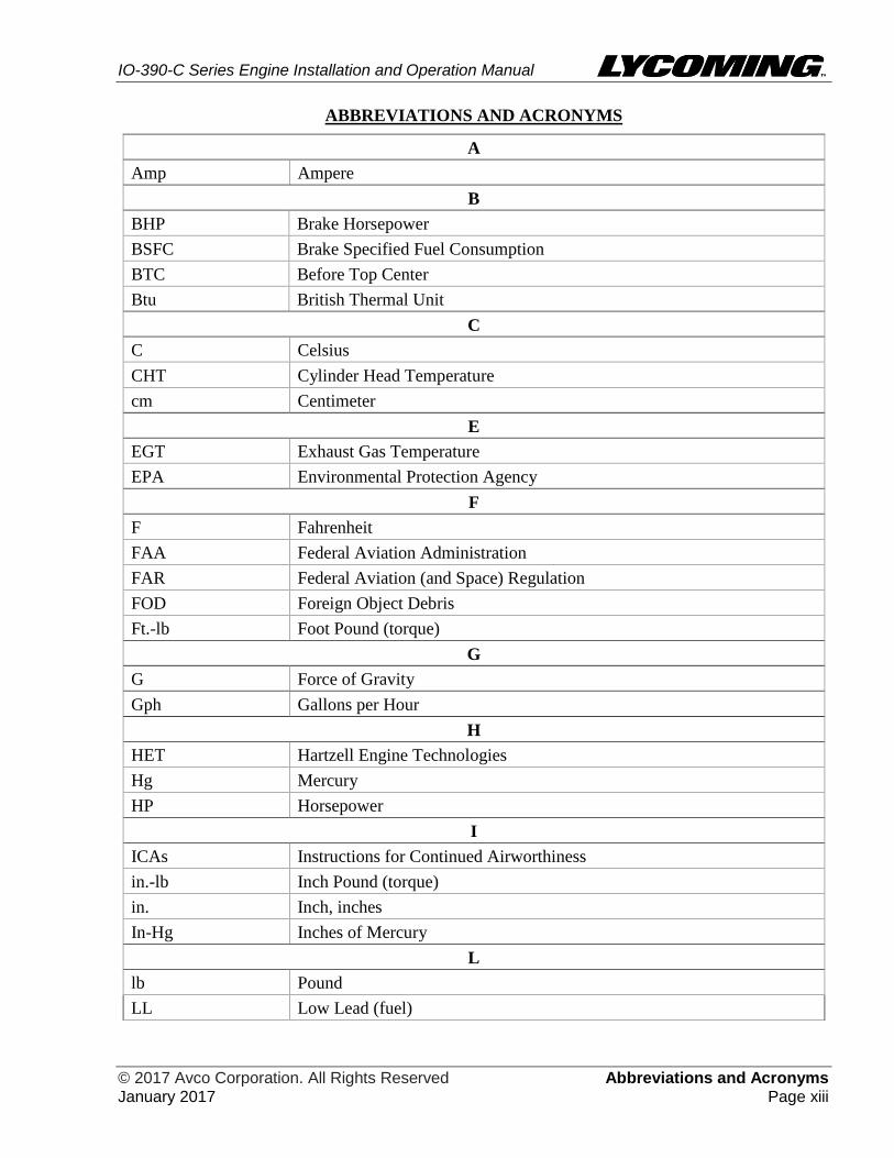
ABBREVIATIONS AND ACRONYMS
A
Amp Ampere
B
BHP Brake Horsepower
BSFC Brake Specified Fuel Consumption
BTC Before Top Center
Btu British Thermal Unit
C
C Celsius
CHT Cylinder Head Temperature
cm Centimeter
E
EGT Exhaust Gas Temperature
EPA Environmental Protection Agency
F
F Fahrenheit
FAA Federal Aviation Administration
FAR Federal Aviation (and Space) Regulation
FOD Foreign Object Debris
Ft.-lb Foot Pound (torque)
G
G Force of Gravity
Gph Gallons per Hour
H
HET Hartzell Engine Technologies
Hg Mercury
HP Horsepower
I
ICAs Instructions for Continued Airworthiness
in.-lb Inch Pound (torque)
in. Inch, inches
In-Hg Inches of Mercury
L
lb Pound
LL Low Lead (fuel)

IO-390-C Series Engine Installation and Operation Manual
Abbreviations and Acronyms © 2017 Avco Corporation. All Rights Reserved Page xiv January 2017
ABBREVIATIONS AND ACRONYMS (CONT.)
K
kPa Kilopascal
M
mm Millimeter
MSB Mandatory Service Bulletin
N
Nm Newton Meter
P
P/N Part Number
POH Pilot’s Operating Handbook
ppm Particles per Million
psi Pounds per Square Inch
R
rpm Revolutions per Minute
S
SAE Society of Automotive Engineers
SB Service Bulletin
SI Service Instruction
STC Supplemental Type Certificate
V
V Volt, Voltage

IO-390-C Series Engine Installation and Operation Manual
© 2017 Avco Corporation. All Rights Reserved Introduction January 2017 Page xv
INTRODUCTION
Engine Model Nomenclature
The table below identifies the basic nomenclature of the IO-390 engine models. Hyphenated
numbers and letters in the suffix (C1A6, C3A6, C1B6, or C3B6) of the engine model number are
configuration designations associated with the core engine.
Model Number Meaning
I Fuel Injected
O Horizontally Opposed
390 Displacement in cubic inches
Scope of this Manual
This manual supplies instructions (in compliance with Federal Aviation Regulations FARs 33.5 and
21.50) for engine description, uncrating procedures, acceptance check, engine lift procedure, engine
preservation and storage, depreservation, engine installation requirements, engine installation,
operation and stop procedures, engine initiation (break-in/flight test), fuels and oil to be used, and
operating specifications for IO-390-C series Lycoming engines.
The installation instructions in this manual are basic guidelines. When installing the engine in the
airframe, follow the airframe manufacturer’s installation instructions.
For maintenance procedures, such as: oil changes, oil addition, oil filter replacement/oil pressure
screen cleaning, routine time-interval inspections, routine service, spark plug replacement/inspection
procedures, cylinder inspection, fuel system inspection, scheduled servicing procedures,
airworthiness limitations, fault isolation guidelines and procedures to replace components and to
disassemble and assemble the engine, refer to the IO-390-C Series Engine Maintenance Manual.
For spare parts information, refer to the IO-390-C Series Illustrated Parts Catalog.
Refer to the latest revision of the Service Table of Limits - SSP-1776, for dimensions, clearances,
measurements, and torque values.
Service Bulletins, Service Instructions, and Service Letters
As advancements in technological applications on this engine continue, Lycoming Engines will
make future revisions to this manual. However, if more timely distribution is necessary, Lycoming
Engines supplies subscribers with up-to-date Service Bulletins (SBs), Service Instructions (SIs) and
Service Letters (which are abbreviated with a capital “L” followed by the number, example L180).
Special Advisories (SAs) are supplied as necessary without a subscription.
For additional publication information, look on Lycoming’s website (Lycoming.com) or speak to
Lycoming Engines by telephone: U.S. and Canada toll free: +1(800) 258-3279; or Direct: +1 (570)
323-6181.
Applicable information from Lycoming Service Bulletins, Service Instructions, and Service Letters
are included in this manual at the time of publication. Any new service information will be included
in the next update of the manual.
Reminder: Unless otherwise specified, Lycoming Engines' service documents (which have a later
date than this manual) that pertain to the engine models in this manual supersede
procedures in this manual.
For reference and future updates, the Service Document List at the front of this manual identifies the
service documents included in this manual.

IO-390-C Series Engine Installation and Operation Manual
Introduction © 2017 Avco Corporation. All Rights Reserved Page xvi January 2017
List of Publications
Refer to the latest revision of Service Letter No. L114 for a list of Lycoming Engines' publications.
Instructions for Continued Airworthiness
The IO-390-C Series Engine Maintenance Manual, latest revision of the Service Table of Limits -
SSP-1776, and service documents make up the complete set of Instructions for Continued
Airworthiness (ICAs). The ICAs are prepared by Lycoming Engines and are accepted by the Federal
Aviation Administration (FAA).
Compliance Requirements
OPERATE THIS ENGINE IN ACCORDANCE WITH SPECIFICATIONS IN
APPENDIX A OF THIS MANUAL. OPERATING THE ENGINE BEYOND
SPECIFIED OPERATING LIMITS CAN CAUSE PERSONAL INJURY
AND/OR DAMAGE TO THE ENGINE.
YOU ALSO MUST COMPLETE THE NECESSARY SERVICE
PROCEDURES IDENTIFIED IN LYCOMING ENGINES' MAINTENANCE
MANUAL FOR THIS ENGINE AS WELL AS ANY APPLICABLE SERVICE
DOCUMENTS. LYCOMING ENGINES' SERVICE DOCUMENTS WRITTEN
AT A LATER DATE SUPERSEDE PROCEDURES IN THIS MANUAL.
PROCEDURES IN THE MAINTENANCE MANUALS MUST BE DONE BY
QUALIFIED PERSONNEL WITH THE REQUISITE CERTIFICATIONS.
Warning, Cautions, and Notices
Be sure to read and obey the Warnings, Cautions and Notices in this manual and in service
documents. Although Lycoming Engines cannot know all possible hazards or damages, it makes a
reasonable effort to supply the best possible guidance and recommended practices for safe operation
and maintenance of its engines.
The table below defines the four types of safety advisory messages used in this manual per the
American National Standard and ANSI Z535-6-2006.
Safety Advisory Conventions
Advisory Word Definition
DANGER: Indicates a hazardous situation which, if not avoided, will result
in death or serious injury. This signal word is to be limited to the
most extreme situations.
Indicates a hazardous situation which, if not avoided, could
result in death or serious injury.
Indicates a hazardous situation which, if not avoided, could
result in minor or moderate injury. It can also be used without
the safety alert symbol as an alternative to "NOTICE."
NOTICE: The preferred signal word to address practices not related to
personal injury.
NOTICE: In this manual, the word "recommended" refers to "best practices."

IO-390-C Series Engine Installation and Operation Manual
© 2017 Avco Corporation. All Rights Reserved Introduction January 2017 Page xvii
Simplified Technical English
The text in the manual is written in Simplified Technical English in compliance with FAA
requirements and to make translation into other languages easier.
Figures
Figures in this manual are for conceptual illustrative purposes only. Figures always start as Figure 1
in each chapter.
Copyright
This publication is a copyrighted work. All rights reserved by Lycoming Engines. Content in this
manual cannot be changed or released as a reprint, electronic media output, or web communiqué
without written permission from Lycoming Engines.
Environmental Compliance
Lycoming Engines recommends that engine owners and engine service personnel be in compliance
with all federal, state, and local environmental regulations when solvents, paint, fuel, oil, chemicals,
or other consumables are used in engine service.
Supplemental Service Information
Refer to the latest revision of Service Letter No. L114 for a list of Lycoming publications.
Feedback
To supply comments, suggestions, or corrections to this manual, either call Lycoming Engines
Customer Service at the phone number in the front of this manual or use the Lycoming.com website.

IO-390-C Series Engine Installation and Operation Manual
Introduction © 2017 Avco Corporation. All Rights Reserved Page xviii January 2017
This page intentionally left blank.

IO-390-C Series Engine Installation and Operation Manual
© 2017 Avco Corporation. All Rights Reserved System Description January 2017 Page 1
SYSTEM DESCRIPTION
The Lycoming IO-390-C series engines are direct-drive four-cylinder, horizontally opposed, fuel-
injected, air-cooled engines. Each engine has tuned induction and a down exhaust.
There are different IO-390-C engine models. Figures 1A and 1B show the IO-390-C engine models.
The main difference between the engine models has to do with the location of the propeller
governor. The IO-390-C1A6 and -C3A6 models (Figure 1A) have an optional propeller governor
installed on the rear of the engine. Whereas, on the IO-390-C1B6 and -C3B6 engine models (Figure
1B), the propeller governor is installed on the front of the crankcase.
There are different propeller flange bushing configurations for these engine models. Refer to the
latest revision of Service Instruction No. SI-1098 for the configuration for your engine model.
NOTICE: Refer to Appendix C for engine performance data.
Figure 1A
IO-390-C1A6, -C3A6 Engine
Figure 1B
IO-390-C1B6, -C3B6 Engine
Cylinders
There are four cylinders on this engine.
Each cylinder (Figure 2) contains a
cylinder head, barrel, piston, angled intake
and exhaust valve guides and valve seats,
rocker shafts, rocker covers, and fins.
Fuel and air enter the cylinder through the
cylinder head for mixing and combustion
within the cylinder.
The engine has intercylinder cooling
baffles.
Figure 2
Engine Cylinder
IO-390-C Series Engine Installation and Operation Manual
System Description © 2017 Avco Corporation. All Rights Reserved Page 2 January 2017
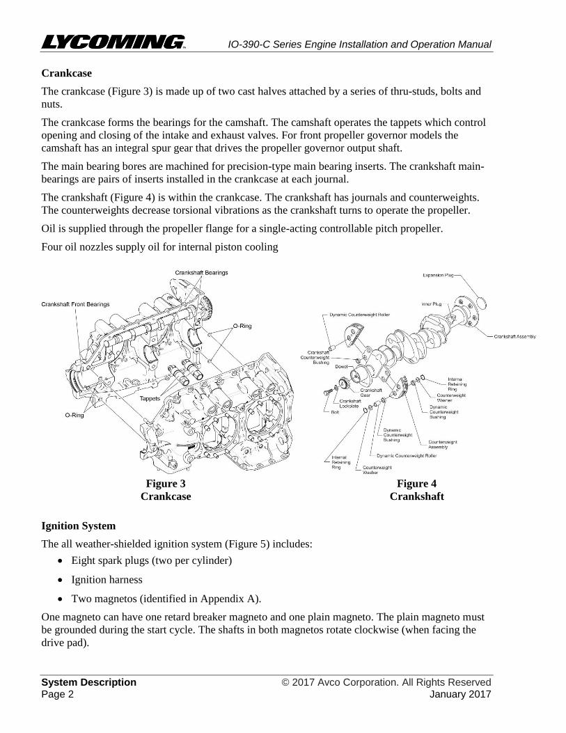
Crankcase
The crankcase (Figure 3) is made up of two cast halves attached by a series of thru-studs, bolts and
nuts.
The crankcase forms the bearings for the camshaft. The camshaft operates the tappets which control
opening and closing of the intake and exhaust valves. For front propeller governor models the
camshaft has an integral spur gear that drives the propeller governor output shaft.
The main bearing bores are machined for precision-type main bearing inserts. The crankshaft main-
bearings are pairs of inserts installed in the crankcase at each journal.
The crankshaft (Figure 4) is within the crankcase. The crankshaft has journals and counterweights.
The counterweights decrease torsional vibrations as the crankshaft turns to operate the propeller.
Oil is supplied through the propeller flange for a single-acting controllable pitch propeller.
Four oil nozzles supply oil for internal piston cooling
Figure 3
Crankcase
Figure 4
Crankshaft
Ignition System
The all weather-shielded ignition system (Figure 5) includes:
Eight spark plugs (two per cylinder)
Ignition harness
Two magnetos (identified in Appendix A).
One magneto can have one retard breaker magneto and one plain magneto. The plain magneto must
be grounded during the start cycle. The shafts in both magnetos rotate clockwise (when facing the
drive pad).

IO-390-C Series Engine Installation and Operation Manual
© 2017 Avco Corporation. All Rights Reserved System Description January 2017 Page 3
Figure 5
Ignition System
Starter
The engine can have either a 12V or 24V starter (Figure 6). Refer to Appendix A.
Figure 6
Starter
IO-390-C Series Engine Installation and Operation Manual
System Description © 2017 Avco Corporation. All Rights Reserved Page 4 January 2017
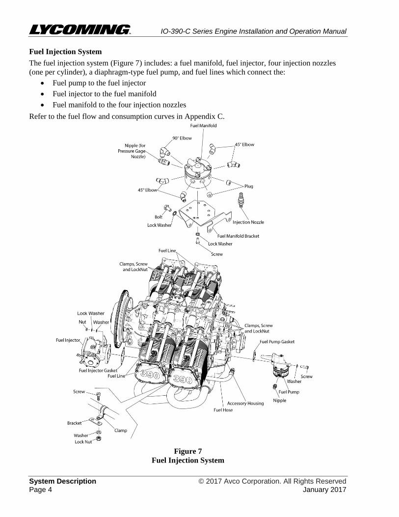
Fuel Injection System
The fuel injection system (Figure 7) includes: a fuel manifold, fuel injector, four injection nozzles
(one per cylinder), a diaphragm-type fuel pump, and fuel lines which connect the:
Fuel pump to the fuel injector
Fuel injector to the fuel manifold
Fuel manifold to the four injection nozzles
Refer to the fuel flow and consumption curves in Appendix C.
Figure 7
Fuel Injection System
IO-390-C Series Engine Installation and Operation Manual
© 2017 Avco Corporation. All Rights Reserved System Description January 2017 Page 5
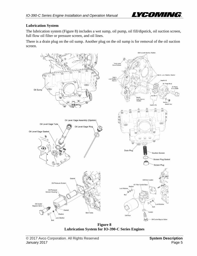
Lubrication System
The lubrication system (Figure 8) includes a wet sump, oil pump, oil fill/dipstick, oil suction screen,
full flow oil filter or pressure screen, and oil lines.
There is a drain plug on the oil sump. Another plug on the oil sump is for removal of the oil suction
screen.
Figure 8
Lubrication System for IO-390-C Series Engines

IO-390-C Series Engine Installation and Operation Manual
System Description © 2017 Avco Corporation. All Rights Reserved Page 6 January 2017
Cylinder Number Designations
The propeller is at the front of the engine and the accessories are at the rear of the engine.
When viewed from the top of the engine, the left side cylinders are 2-4. Cylinder 2 is at the
front of the engine (Figure 9).
When viewed from the top of the engine, the cylinders on the right are 1-3. Cylinder 1 is at the
front of the engine.
The firing order of the cylinders is 1-3-2-4.
Figure 9
Cylinder Number Designation

IO-390-C Series Engine Installation and Operation Manual
© 2017 Avco Corporation. All Rights Reserved Engine Reception and Lift January 2017 Page 7
ENGINE RECEPTION AND LIFT
Uncrate Procedure for a New, Rebuilt, or Overhauled Engine
NOTICE: If the engine is to be stowed, refer to the chapter “Engine Preservation and Storage” in
this manual.
1. When the engine is received, make sure that the shipping container or box is not damaged. If the
engine crate is damaged, speak to Lycoming Engine’s Service Department and the freight
shipper.
A. These engines are usually sent in a box where the engine is attached to a pallet within the
box. The engine can be in a plastic bag or wrapped and it could have a top foam pillow.
URETHANE FOAM IS FLAMMABLE! DO NOT PUT URETHANE FOAM
NEAR OPEN FLAMES OR ANY OTHER DIRECT OR INDIRECT HIGH
TEMPERATURE SOURCE OF IGNITION SUCH AS WELDING,
BURNING, ETC.
2. If the crate is acceptable, remove the engine from the crate. To uncrate the engine:
A. Cut the bands on the box.
B. If there are staples at the bottom perimeter around the box, remove the staples and lift away
the box. If there are no staples on the bottom perimeter of the box, cut the tape at the top of
the box with a knife and open the box.
C. Remove a few top slats of the crate and then remove the top pillow.
DO NOT TURN THE CRANKSHAFT OF AN ENGINE WITH
PRESERVATIVE OIL BEFORE REMOVAL OF THE BOTTOM SHIPPING
OR SPARK PLUGS. OTHERWISE ENGINE DAMAGE, CAUSED BY
HYDRAULIC LOCK, CAN OCCUR.
D. Look for any fluid (oil or fuel) on the skid or below the engine. If fluid is found, identify the
source.
Acceptance Check
1. Every engine sent from the factory is identified by a unique
serial number. The engine serial number is identified on the
engine data plate (Figure 1). Do not remove the engine data
plate.
2. Make sure that the engine serial number and model number on
the engine data plate (Figure 1) are the same as specified in
the engine logbook and on the packing slip.
3. Examine the engine for damage or corrosion before lifting. If
the engine is damaged or has corrosion, identify the areas of
damage and corrosion. Speak to Lycoming Engines’ Service
Department and the Freight Shipper.
4. If a data plate is ever lost or damaged, refer to the latest
revision of Service Instruction No. SI-1304 for data plate
replacement information.
Figure 1
Engine Data Plate
IO-390-C Series Engine Installation and Operation Manual
Engine Reception and Lift © 2017 Avco Corporation. All Rights Reserved Page 8 January 2017
NOTICE: Do not lift, install or store a damaged or corroded engine (prior to receiving instructions
from Lycoming Engines or the freight shipper).
5. If the engine is not damaged or corroded, it can be installed or stored. If the engine is to be
installed within 5 days after uncrating, refer to the section “Step 1. Prepare the Engine” in the
“Requirements for Engine Installation” chapter.
6. Refer to the section “Lift the Engine” in this chapter and lift the engine.
Engine Preservative Oil Removal
The engine is sent with preservative oil in the cylinder and preservative oil in the crankcase. Refer to
the “Prepare a New, Rebuilt, or Overhauled Engine for Installation” section in the “Requirements for
Engine Installation” chapter in this manual.
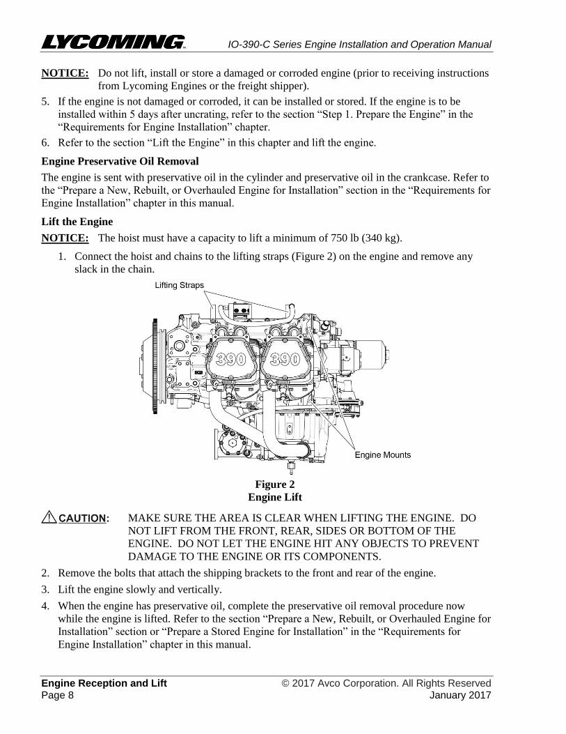
Lift the Engine
NOTICE: The hoist must have a capacity to lift a minimum of 750 lb (340 kg).
1. Connect the hoist and chains to the lifting straps (Figure 2) on the engine and remove any
slack in the chain.
Figure 2
Engine Lift
MAKE SURE THE AREA IS CLEAR WHEN LIFTING THE ENGINE. DO
NOT LIFT FROM THE FRONT, REAR, SIDES OR BOTTOM OF THE
ENGINE. DO NOT LET THE ENGINE HIT ANY OBJECTS TO PREVENT
DAMAGE TO THE ENGINE OR ITS COMPONENTS.
2. Remove the bolts that attach the shipping brackets to the front and rear of the engine.
3. Lift the engine slowly and vertically.
4. When the engine has preservative oil, complete the preservative oil removal procedure now
while the engine is lifted. Refer to the section “Prepare a New, Rebuilt, or Overhauled Engine for
Installation” section or “Prepare a Stored Engine for Installation” in the “Requirements for
Engine Installation” chapter in this manual.
IO-390-C Series Engine Installation and Operation Manual
© 2017 Avco Corporation. All Rights Reserved Requirements for Engine Installation January 2017 Page 9
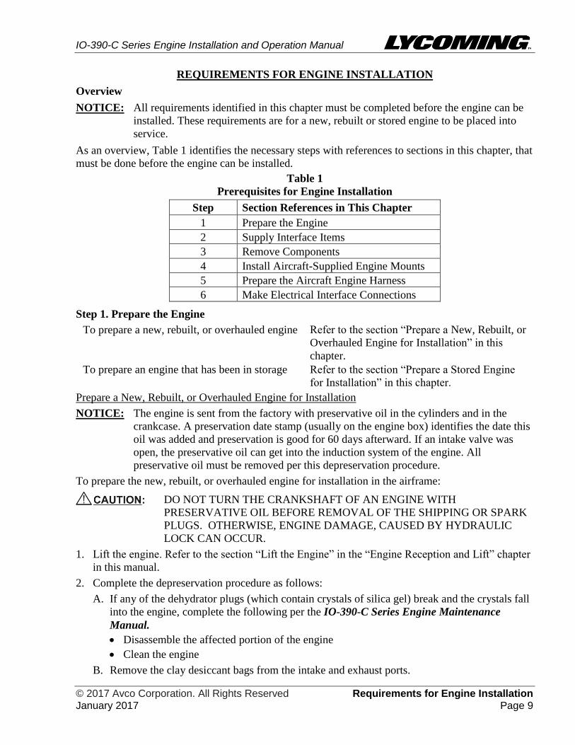
REQUIREMENTS FOR ENGINE INSTALLATION
Overview
NOTICE: All requirements identified in this chapter must be completed before the engine can be
installed. These requirements are for a new, rebuilt or stored engine to be placed into
service.
As an overview, Table 1 identifies the necessary steps with references to sections in this chapter, that
must be done before the engine can be installed.
Table 1
Prerequisites for Engine Installation
Step Section References in This Chapter
1 Prepare the Engine
2 Supply Interface Items
3 Remove Components
4 Install Aircraft-Supplied Engine Mounts
5 Prepare the Aircraft Engine Harness
6 Make Electrical Interface Connections
Step 1. Prepare the Engine
To prepare a new, rebuilt, or overhauled engine Refer to the section “Prepare a New, Rebuilt, or
Overhauled Engine for Installation” in this
chapter.
To prepare an engine that has been in storage Refer to the section “Prepare a Stored Engine
for Installation” in this chapter.
Prepare a New, Rebuilt, or Overhauled Engine for Installation
NOTICE: The engine is sent from the factory with preservative oil in the cylinders and in the
crankcase. A preservation date stamp (usually on the engine box) identifies the date this
oil was added and preservation is good for 60 days afterward. If an intake valve was
open, the preservative oil can get into the induction system of the engine. All
preservative oil must be removed per this depreservation procedure.
To prepare the new, rebuilt, or overhauled engine for installation in the airframe:
DO NOT TURN THE CRANKSHAFT OF AN ENGINE WITH
PRESERVATIVE OIL BEFORE REMOVAL OF THE SHIPPING OR SPARK
PLUGS. OTHERWISE, ENGINE DAMAGE, CAUSED BY HYDRAULIC
LOCK CAN OCCUR.
1. Lift the engine. Refer to the section “Lift the Engine” in the “Engine Reception and Lift” chapter
in this manual.
2. Complete the depreservation procedure as follows:
A. If any of the dehydrator plugs (which contain crystals of silica gel) break and the crystals fall
into the engine, complete the following per the IO-390-C Series Engine Maintenance
Manual.
Disassemble the affected portion of the engine
Clean the engine
B. Remove the clay desiccant bags from the intake and exhaust ports.

IO-390-C Series Engine Installation and Operation Manual
Requirements for Engine Installation © 2017 Avco Corporation. All Rights Reserved Page 10 January 2017
C. Put a container under the engine to collect the cylinder preservative oil.
D. Remove the shipping plugs or spark plugs installed in the lower spark plug holes.
E. Remove the desiccant plugs or spark plugs from the upper spark plugs holes.
F. Turn the crankshaft through three or four complete revolutions to remove the cylinder
preservative oil from the cylinders.
G. Collect the cylinder preservative oil as it drains out of the lower spark plug holes.
H. Tilt the engine to one side until the spark plug holes on that side are vertical.
I. Turn the crankshaft two revolutions and let the oil drain out through the spark plug holes.
J. Tilt the engine to the other side until the spark plug holes on that side are vertical.
K. Turn the crankshaft two revolutions and let the oil drain out through the spark plug holes.
3. Examine the cylinder bores with a borescope for rust and contamination. Refer to Chapter 72-30
in the IO-390-C Series Engine Maintenance Manual.
4. If any corrosion or unusual conditions are found, speak to Lycoming Engine’s Service
Department.
5. Drain preservative oil from the oil sump:
A. Put a 15-quart (14-liter) capacity container under the oil sump.
B. Remove the safety wire/cable from the oil sump drain plug. Discard the safety wire/cable.
C. Remove the oil sump drain plug.
D. Drain the remaining preservative oil from the oil sump into the container.
NOTICE: If some preservative oil stays in the engine, it will not damage the engine. The
preservative oil will be removed after the first 25 hours of operation during the oil
change.
E. Apply one to two drops of Loctite® 564
™ to the threads of the oil sump drain plug and install
the oil sump drain plug in the oil sump. Torque the drain plug in accordance with the latest
revision of the Service Table of Limits - SSP-1776.
MAKE SURE THAT THE OIL SUMP DRAIN PLUG IS INSTALLED
TIGHTLY. IF THE DRAIN PLUG IS NOT TIGHTLY INSTALLED AND
LEAKS, ENGINE FAILURE CAN OCCUR.
F. Safety wire/cable the oil sump drain plug in accordance with the standard practices per the
latest revision of AC43.13-1B or the latest revision of Service Instruction No. SI-1566.
6. Drain the fuel pump:
A. Put a collection container underneath the fuel pump.
B. Remove the shipping caps installed on the fuel pump.
C. Let any preservative fluid drain from the fuel pump into a collection container.
D. Remove the collection container.
E. Reinstall the shipping cap on the main fuel inlet on the fuel pump.
F. Install all shipped loose components of the fuel system.
G. Connect the fuel lines to all fuel system components. Refer to Chapter 73-10 in the IO-390-C
Series Engine Maintenance Manual.
IO-390-C Series Engine Installation and Operation Manual
© 2017 Avco Corporation. All Rights Reserved Requirements for Engine Installation January 2017 Page 11
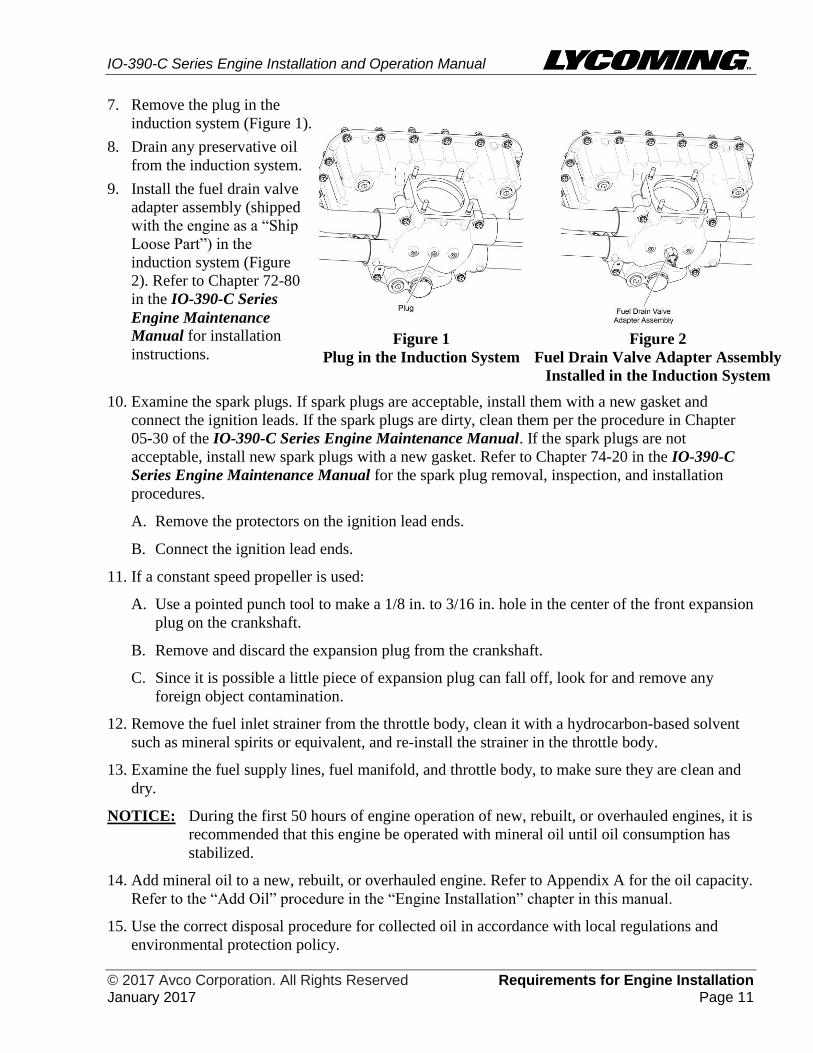
7. Remove the plug in the
induction system (Figure 1).
8. Drain any preservative oil
from the induction system.
9. Install the fuel drain valve
adapter assembly (shipped
with the engine as a “Ship
Loose Part”) in the
induction system (Figure
2). Refer to Chapter 72-80
in the IO-390-C Series
Engine Maintenance
Manual for installation
instructions.
Figure 1
Plug in the Induction System
Figure 2
Fuel Drain Valve Adapter Assembly
Installed in the Induction System
10. Examine the spark plugs. If spark plugs are acceptable, install them with a new gasket and
connect the ignition leads. If the spark plugs are dirty, clean them per the procedure in Chapter
05-30 of the IO-390-C Series Engine Maintenance Manual. If the spark plugs are not
acceptable, install new spark plugs with a new gasket. Refer to Chapter 74-20 in the IO-390-C
Series Engine Maintenance Manual for the spark plug removal, inspection, and installation
procedures.
A. Remove the protectors on the ignition lead ends.
B. Connect the ignition lead ends.
11. If a constant speed propeller is used:
A. Use a pointed punch tool to make a 1/8 in. to 3/16 in. hole in the center of the front expansion
plug on the crankshaft.
B. Remove and discard the expansion plug from the crankshaft.
C. Since it is possible a little piece of expansion plug can fall off, look for and remove any
foreign object contamination.
12. Remove the fuel inlet strainer from the throttle body, clean it with a hydrocarbon-based solvent
such as mineral spirits or equivalent, and re-install the strainer in the throttle body.
13. Examine the fuel supply lines, fuel manifold, and throttle body, to make sure they are clean and
dry.
NOTICE: During the first 50 hours of engine operation of new, rebuilt, or overhauled engines, it is
recommended that this engine be operated with mineral oil until oil consumption has
stabilized.
14. Add mineral oil to a new, rebuilt, or overhauled engine. Refer to Appendix A for the oil capacity.
Refer to the “Add Oil” procedure in the “Engine Installation” chapter in this manual.
15. Use the correct disposal procedure for collected oil in accordance with local regulations and
environmental protection policy.
IO-390-C Series Engine Installation and Operation Manual
Requirements for Engine Installation © 2017 Avco Corporation. All Rights Reserved Page 12 January 2017
Prepare a Stored Engine for Installation
NOTICE: If the engine had been stored at temperatures below 10°F (-12°C), put the engine in an
environment of at least 70°F (21°C) for 24 hours before completing this depreservation
procedure. If this thawing is not possible, apply heat to cylinders with heat lamps.
Since an engine in storage has preservative oil, complete this depreservation procedure to prepare the
engine for installation into the airframe:
1. Lift the engine. Refer to the section “Lift the Engine” in the “Engine Reception and Lift” chapter
in this manual.
2. Put a container under the engine to collect the cylinder preservative oil.
DO NOT TURN THE CRANKSHAFT OF AN ENGINE WITH PRESERVATIVE
OIL BEFORE REMOVAL OF THE SPARK PLUGS. ENGINE DAMAGE
CAUSED BY HYDRAULIC LOCK CAN OCCUR.
3. If the engine has been preserved and/or has been in long-term storage, remove the items used in
preservation as follows:
A. Remove and discard the seals.
B. Remove tape residue with solvent.
C. Remove and discard the dehydrator plugs (if installed).
D. Remove and discard the clay desiccant bags for the intake and exhaust ports.
NOTICE: If any of these plugs break and the crystals fall into the engine, complete the following
procedure per the IO-390-C Series Engine Maintenance Manual.
Disassemble the engine
Clean the engine
4. Examine the engine for any damage.
5. If the engine is not damaged, go to the next step. If damage is found, identify and correct or
repair the problem. Record findings and corrective action in the engine logbook.
6. Remove the spark plugs or protective plugs from the top and bottom spark plug holes per
instructions in Chapter 74-20 in the IO-390-C Series Engine Maintenance Manual.
7. Remove any other moisture-prevention seals and covers from the engine.
IF PRESERVATIVE OIL TOUCHES PAINTED SURFACES, REMOVE THE
OIL IMMEDIATELY TO PREVENT DAMAGE TO THE PAINT.
NOTICE: To touch-up paint, refer to Chapter 72-10 in the IO-390-C Series Engine Maintenance
Manual.
8. Complete the preservative oil removal procedure as follows:
A. Turn the crankshaft through three or four revolutions to remove the cylinder preservative oil
from the cylinders.
B. Collect the cylinder preservative oil as it drains out of the lower spark plug holes.
C. Tilt the engine to one side, until the spark plug holes on that side are vertical.
D. Turn the crankshaft two revolutions and let the oil drain out through the spark plug holes.
E. Tilt the engine to the other side until the spark plug holes on that side are vertical.
F. Turn the crankshaft two revolutions and let the oil drain out through the spark plug holes.
9. Examine the cylinder bores with a borescope for rust and contamination. Refer to Chapter 72-30
in the IO-390-C Series Engine Maintenance Manual.
10. If any corrosion or unusual conditions are found, speak to Lycoming Engine’s Service
Department.

IO-390-C Series Engine Installation and Operation Manual
© 2017 Avco Corporation. All Rights Reserved Requirements for Engine Installation January 2017 Page 13
11. Drain preservative oil from the oil sump:
A. Put a 15-quart (14-liter) capacity container under the oil sump.
B. Remove the safety wire/cable from the oil sump drain plug. Discard the safety wire/cable.
C. Remove the oil sump drain plug.
D. Drain the remaining preservative oil from the oil sump into the container.
NOTICE: If some preservative oil stays in the engine, it will not damage the engine. The
preservative oil will be removed after the first 25 hours of operation during the oil
change.
E. Remove, examine, clean, and reinstall the oil suction screen per the “Oil Suction Screen
Removal/Inspection/Cleaning/Installation” section in Chapter 12-10 of the IO-390-C Series
Engine Maintenance Manual.
F. Apply one to two drops of Loctite® 564
™ to the threads of the oil sump drain plug and install
the oil sump drain plug in the oil sump. Torque the drain plug in accordance with the latest
revision of the Service Table of Limits - SSP-1776.
MAKE SURE THAT THE OIL SUMP DRAIN PLUG AND THE SUCTION
SCREEN PLUG ARE INSTALLED TIGHTLY. IF THE DRAIN PLUG AND
SCREEN PLUG ARE NOT TIGHTLY INSTALLED AND LEAK, ENGINE
FAILURE CAN OCCUR.
G. Safety wire/cable the oil sump drain plug in accordance with the standard practices per the
latest revision of AC43.13-1B or the latest revision of Service Instruction No. SI-1566.
12. Remove the oil filter and install a new oil filter. Refer to Chapter 12-10 in the IO-390-C Series
Engine Maintenance Manual.
13. If the front expansion plug is installed and a constant speed propeller is to be used:
A. Use a pointed punch tool to make a 1/8 in. to 3/16 in. hole in the center of the front
crankshaft plug.
B. Remove and discard the expansion plug from the crankshaft.
C. Since it is possible a little piece of expansion plug can fall off, look for and remove any
foreign object contamination.
14. Refer to Chapter 74-20 in the IO-390-C Series Engine Maintenance Manual to:
A. Examine the spark plugs.
B. If spark plugs are acceptable, install them with a new gasket. If the spark plugs are dirty,
clean them per the procedure in Chapter 05-30 of the IO-390-C Series Engine Maintenance
Manual. If the spark plugs are not acceptable, install new spark plugs with a new gasket.
C. Remove the protectors on the ignition lead ends.
D. Connect the ignition lead ends.
15. Remove the fuel inlet strainer from the throttle body and clean it with a hydrocarbon-based
solvent such as mineral spirits or equivalent and re-install the strainer on the throttle body.
16. Examine the fuel supply lines, fuel manifold, and throttle body to make sure they are clean and
dry.
17. Add specified oil per Appendix A. Refer to the “Add Oil” procedure in the “Engine Installation”
chapter in this manual.
18. Use the correct procedure for disposal of drained oil and fuel in accordance with local, state,
federal, and environmental protection regulations.
IO-390-C Series Engine Installation and Operation Manual
Requirements for Engine Installation © 2017 Avco Corporation. All Rights Reserved Page 14 January 2017
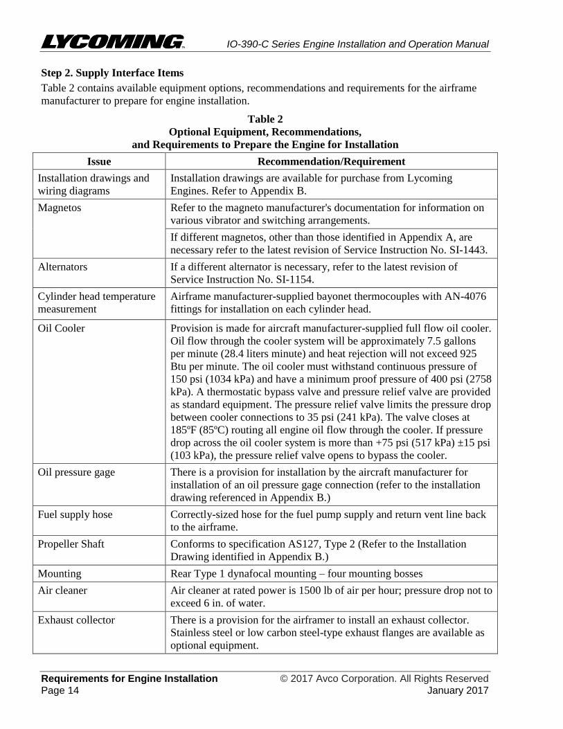
Step 2. Supply Interface Items
Table 2 contains available equipment options, recommendations and requirements for the airframe
manufacturer to prepare for engine installation.
Table 2
Optional Equipment, Recommendations,
and Requirements to Prepare the Engine for Installation
Issue Recommendation/Requirement
Installation drawings and
wiring diagrams
Installation drawings are available for purchase from Lycoming
Engines. Refer to Appendix B.
Magnetos Refer to the magneto manufacturer's documentation for information on
various vibrator and switching arrangements.
If different magnetos, other than those identified in Appendix A, are
necessary refer to the latest revision of Service Instruction No. SI-1443.
Alternators If a different alternator is necessary, refer to the latest revision of
Service Instruction No. SI-1154.
Cylinder head temperature
measurement
Airframe manufacturer-supplied bayonet thermocouples with AN-4076
fittings for installation on each cylinder head.
Oil Cooler Provision is made for aircraft manufacturer-supplied full flow oil cooler.
Oil flow through the cooler system will be approximately 7.5 gallons
per minute (28.4 liters minute) and heat rejection will not exceed 925
Btu per minute. The oil cooler must withstand continuous pressure of
150 psi (1034 kPa) and have a minimum proof pressure of 400 psi (2758
kPa). A thermostatic bypass valve and pressure relief valve are provided
as standard equipment. The pressure relief valve limits the pressure drop
between cooler connections to 35 psi (241 kPa). The valve closes at
185ºF (85ºC) routing all engine oil flow through the cooler. If pressure
drop across the oil cooler system is more than +75 psi (517 kPa) ±15 psi
(103 kPa), the pressure relief valve opens to bypass the cooler.
Oil pressure gage There is a provision for installation by the aircraft manufacturer for
installation of an oil pressure gage connection (refer to the installation
drawing referenced in Appendix B.)
Fuel supply hose Correctly-sized hose for the fuel pump supply and return vent line back
to the airframe.
Propeller Shaft Conforms to specification AS127, Type 2 (Refer to the Installation
Drawing identified in Appendix B.)
Mounting Rear Type 1 dynafocal mounting – four mounting bosses
Air cleaner Air cleaner at rated power is 1500 lb of air per hour; pressure drop not to
exceed 6 in. of water.
Exhaust collector There is a provision for the airframer to install an exhaust collector.
Stainless steel or low carbon steel-type exhaust flanges are available as
optional equipment.
IO-390-C Series Engine Installation and Operation Manual
© 2017 Avco Corporation. All Rights Reserved Requirements for Engine Installation January 2017 Page 15
Step 3. Remove Components
It could be necessary to temporarily remove a component, to install the engine in its compartment on
the aircraft.
Remove only the components necessary to enable engine installation.
The component(s) will be re-installed after the engine is installed.
Step 4. Install Aircraft-Supplied Engine Mounts
The airframer is to supply bonded rubber mounts and bolts for attachment to the Type 1 Dynafocal
engine mounts. There are four mounting bosses integral to the crankcase. Refer to the respective
Installation Drawing identified in Appendix B for the applicable engines.
Maximum Allowable Load for the Mounting Attachment and Structure
The Type 1 Dynafocal mounts can withstand a 10 G load per FAA FAR requirements.
Step 5. Prepare the Aircraft Engine Harness
Lycoming Engines can supply a wiring diagram to the aircraft manufacturer which is used to prepare
the aircraft engine harness.
Step 6. Make Electrical Interface Connections
Make electrical interface connections.
Grounding Requirements
Install grounding jumpers from the engine case to the engine mounting frame. (The engine mount
must also be grounded to the airframe).
IO-390-C Series Engine Installation and Operation Manual
Requirements for Engine Installation © 2017 Avco Corporation. All Rights Reserved Page 16 January 2017
This page intentionally left blank.
IO-390-C Series Engine Installation and Operation Manual
© 2017 Avco Corporation. All Rights Reserved Engine Installation January 2017 Page 17
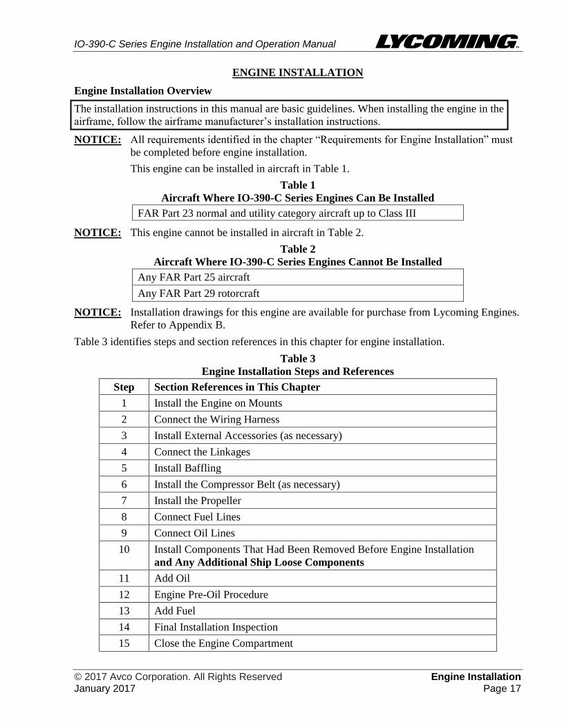
ENGINE INSTALLATION
Engine Installation Overview
The installation instructions in this manual are basic guidelines. When installing the engine in the
airframe, follow the airframe manufacturer’s installation instructions.
NOTICE: All requirements identified in the chapter “Requirements for Engine Installation” must
be completed before engine installation.
This engine can be installed in aircraft in Table 1.
Table 1
Aircraft Where IO-390-C Series Engines Can Be Installed
FAR Part 23 normal and utility category aircraft up to Class III
NOTICE: This engine cannot be installed in aircraft in Table 2.
Table 2
Aircraft Where IO-390-C Series Engines Cannot Be Installed
Any FAR Part 25 aircraft
Any FAR Part 29 rotorcraft
NOTICE: Installation drawings for this engine are available for purchase from Lycoming Engines.
Refer to Appendix B.
Table 3 identifies steps and section references in this chapter for engine installation.
Table 3
Engine Installation Steps and References
Step Section References in This Chapter
1 Install the Engine on Mounts
2 Connect the Wiring Harness
3 Install External Accessories (as necessary)
4 Connect the Linkages
5 Install Baffling
6 Install the Compressor Belt (as necessary)
7 Install the Propeller
8 Connect Fuel Lines
9 Connect Oil Lines
10 Install Components That Had Been Removed Before Engine Installation
and Any Additional Ship Loose Components
11 Add Oil
12 Engine Pre-Oil Procedure
13 Add Fuel
14 Final Installation Inspection
15 Close the Engine Compartment
IO-390-C Series Engine Installation and Operation Manual
Engine Installation © 2017 Avco Corporation. All Rights Reserved Page 18 January 2017
Step 1. Install the Engine on Mounts
MAKE SURE THAT THE ENGINE MOUNTS ARE ALIGNED AND NOT
BENT OR DEFORMED. IF THE ENGINE IS INSTALLED ON DEFORMED
ENGINE MOUNTS OR MISALIGNED, THE ENGINE CAN BE PUT UNDER
UNUSUAL STRESS WHICH CAN CAUSE MALFUNCTION.
1. Lift the engine and put it into the airframe. Refer to the “Lift the Engine” section in the
“Engine Reception and Lift” chapter in this manual.
2. Install hardware to securely attach the engine to the airframe and isolation mounts.
3. Torque the mounting hardware per the aircraft manufacturer’s maintenance manual.
4. Disconnect the hoist from the lifting eyes.
5. Make sure the airframe ground straps are connected to the engine mounts.
Step 2. Connect the Wiring Harness
1. Connect the aircraft engine wiring harness as necessary. Refer to the aircraft manufacturer’s
wiring diagram, specifications and drawings.
2. Connect wiring to the starter.
Step 3. Install External Accessories (as necessary)
1. Remove the accessory drive cover plate and gasket.
2. Install the accessory on the supplied pad in accordance with the aircraft manufacturer’s
instructions. Refer to Table A-3 or A-4 in Appendix A.
3. If necessary, install the propeller governor; use the manufacturer’s supplied gasket and
hardware. Refer to Table A-3 or A-4 in Appendix A.
4. Install the alternator per airframe manufacturer’s instructions.
Step 4. Connect the Linkages
Connect the throttle, mixture, and propeller linkages as necessary in accordance with the aircraft
manufacturer's specifications and drawings.
Step 5. Install Baffling
Install baffling around the engine compartment per the aircraft manufacturer’s instructions.
Step 6. Install the Compressor Belt (as necessary)
Install the compressor belt (which will drive an aircraft-supplied air conditioning unit) in accordance
with aircraft and compressor manufacturer's instructions.
Step 7. Install the Propeller
IF THE CORRECT PROPELLER BUSHING IS NOT INSTALLED IN THE
SPECIFIED LOCATION, THE PROPELLER WILL NOT BE INDEXED
CORRECTLY AND EXCESSIVE PROPELLER BLADE STRESSES CAN
OCCUR.
Install the propeller in accordance with the propeller and aircraft manufacturer's instructions. Make
sure the propeller flange bushings of the correct part number are installed in the correct indexed
location. Refer to the latest revision of Service Instruction No. SI-1098 and any supplements.

IO-390-C Series Engine Installation and Operation Manual
© 2017 Avco Corporation. All Rights Reserved Engine Installation January 2017 Page 19
Step 8. Connect Fuel Lines
1. Before connection of the main fuel inlet line to the fuel pump, remove all contaminants from
aircraft fuel tanks and fuel lines.
REMOVE ANY CONTAMINATION FROM AIRCRAFT FUEL TANKS
AND FUEL LINES. FAILURE TO REMOVE ALL CONTAMINATION
CAN CAUSE PREMATURE FUEL FILTER REPLACEMENT OR
INCORRECT FUEL SYSTEM OPERATION.
2. Remove unwanted material from the aircraft fuel strainer. Let a minimum of 1 gallon (3.8
liters) of fuel flow through the strainer, aircraft fuel filter and fuel supply line.
3. Make sure that the aircraft manufacturer has a fuel filter installed on the aircraft.
4. Remove protective caps from the main fuel inlet.
5. Connect the fuel supply line to the fuel pump inlet. Torque the connections per the aircraft
manufacturer's instructions.
6. Required guidelines for making fuel line connections:
A. Make sure the fuel line is not crimped or kinked, there are no cracks at solder joints, and
the fuel line is in compliance with Figure 1 for the minimum acceptable dimension for a
bend in the fuel line.
NOTICE: Refer to Chapter 73-10 in the IO-390-C Series Engine Maintenance Manual
for suggested routing and configuration arrangement diagrams for fuel lines on
this engine. The fuel line configuration diagram is conceptual and for reference
only. Fuel line routing on your engine could have slightly different
configurations. Fuel lines must be examined every 100 hours per the IO-390-C
Series Engine Maintenance Manual.
B. Make sure that the fuel lines are held in place with the necessary cushioned clamps and
hardware. Make sure the clamps are tightly attached to support the fuel line and to
prevent movement from vibration or motion frequencies. Do NOT use plastic tie straps in
place of cushioned clamps.
DO NOT ROUTE FUEL LINES CLOSE TO HEAT SOURCES. HEAT
CAN DAMAGE THE FUEL LINE AND CAUSE A FUEL LEAK
WHICH COULD LEAD TO CATASTROPHIC ENGINE FAILURE.
C. Do not let fuel lines touch
the engine or aircraft baffle
hardware. There must be a
minimum clearance of 3/16
in. (4.76 mm) between a
fuel line and any engine or
aircraft surface.
Figure 1
Minimum Acceptable Dimension
for a Bend in a Fuel Line
IO-390-C Series Engine Installation and Operation Manual
Engine Installation © 2017 Avco Corporation. All Rights Reserved Page 20 January 2017
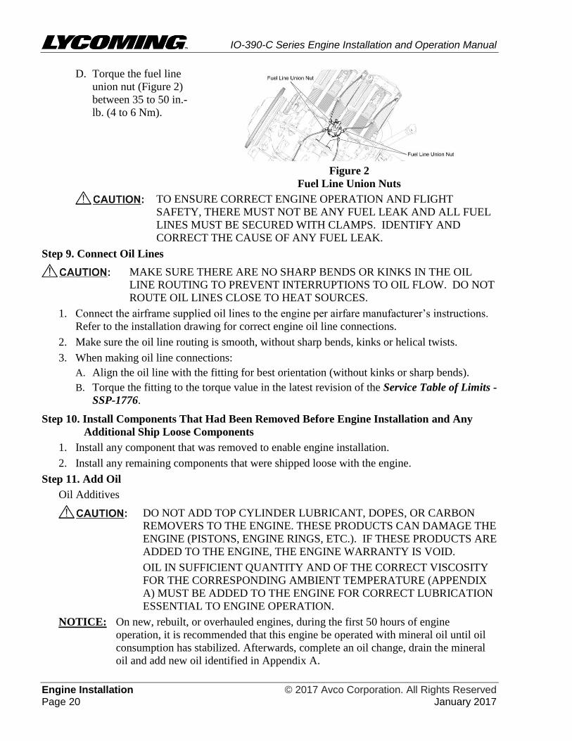
D. Torque the fuel line
union nut (Figure 2)
between 35 to 50 in.-
lb. (4 to 6 Nm).
Figure 2
Fuel Line Union Nuts
TO ENSURE CORRECT ENGINE OPERATION AND FLIGHT
SAFETY, THERE MUST NOT BE ANY FUEL LEAK AND ALL FUEL
LINES MUST BE SECURED WITH CLAMPS. IDENTIFY AND
CORRECT THE CAUSE OF ANY FUEL LEAK.
Step 9. Connect Oil Lines
MAKE SURE THERE ARE NO SHARP BENDS OR KINKS IN THE OIL
LINE ROUTING TO PREVENT INTERRUPTIONS TO OIL FLOW. DO NOT
ROUTE OIL LINES CLOSE TO HEAT SOURCES.
1. Connect the airframe supplied oil lines to the engine per airfare manufacturer’s instructions.
Refer to the installation drawing for correct engine oil line connections.
2. Make sure the oil line routing is smooth, without sharp bends, kinks or helical twists.
3. When making oil line connections:
A. Align the oil line with the fitting for best orientation (without kinks or sharp bends).
B. Torque the fitting to the torque value in the latest revision of the Service Table of Limits -
SSP-1776.
Step 10. Install Components That Had Been Removed Before Engine Installation and Any
Additional Ship Loose Components
1. Install any component that was removed to enable engine installation.
2. Install any remaining components that were shipped loose with the engine.
Step 11. Add Oil
Oil Additives
DO NOT ADD TOP CYLINDER LUBRICANT, DOPES, OR CARBON
REMOVERS TO THE ENGINE. THESE PRODUCTS CAN DAMAGE THE
ENGINE (PISTONS, ENGINE RINGS, ETC.). IF THESE PRODUCTS ARE
ADDED TO THE ENGINE, THE ENGINE WARRANTY IS VOID.
OIL IN SUFFICIENT QUANTITY AND OF THE CORRECT VISCOSITY
FOR THE CORRESPONDING AMBIENT TEMPERATURE (APPENDIX
A) MUST BE ADDED TO THE ENGINE FOR CORRECT LUBRICATION
ESSENTIAL TO ENGINE OPERATION.
NOTICE: On new, rebuilt, or overhauled engines, during the first 50 hours of engine
operation, it is recommended that this engine be operated with mineral oil until oil
consumption has stabilized. Afterwards, complete an oil change, drain the mineral
oil and add new oil identified in Appendix A.
IO-390-C Series Engine Installation and Operation Manual
© 2017 Avco Corporation. All Rights Reserved Engine Installation January 2017 Page 21
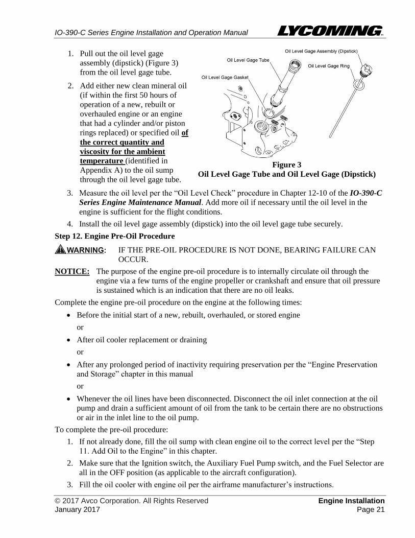
1. Pull out the oil level gage
assembly (dipstick) (Figure 3)
from the oil level gage tube.
2. Add either new clean mineral oil
(if within the first 50 hours of
operation of a new, rebuilt or
overhauled engine or an engine
that had a cylinder and/or piston
rings replaced) or specified oil of
the correct quantity and
viscosity for the ambient
temperature (identified in
Appendix A) to the oil sump
through the oil level gage tube.
Figure 3
Oil Level Gage Tube and Oil Level Gage (Dipstick)
3. Measure the oil level per the “Oil Level Check” procedure in Chapter 12-10 of the IO-390-C
Series Engine Maintenance Manual. Add more oil if necessary until the oil level in the
engine is sufficient for the flight conditions.
4. Install the oil level gage assembly (dipstick) into the oil level gage tube securely.
Step 12. Engine Pre-Oil Procedure
IF THE PRE-OIL PROCEDURE IS NOT DONE, BEARING FAILURE CAN
OCCUR.
NOTICE: The purpose of the engine pre-oil procedure is to internally circulate oil through the
engine via a few turns of the engine propeller or crankshaft and ensure that oil pressure
is sustained which is an indication that there are no oil leaks.
Complete the engine pre-oil procedure on the engine at the following times:
Before the initial start of a new, rebuilt, overhauled, or stored engine
or
After oil cooler replacement or draining
or
After any prolonged period of inactivity requiring preservation per the “Engine Preservation
and Storage” chapter in this manual
or
Whenever the oil lines have been disconnected. Disconnect the oil inlet connection at the oil
pump and drain a sufficient amount of oil from the tank to be certain there are no obstructions
or air in the inlet line to the oil pump.
To complete the pre-oil procedure:
1. If not already done, fill the oil sump with clean engine oil to the correct level per the “Step
11. Add Oil to the Engine” in this chapter.
2. Make sure that the Ignition switch, the Auxiliary Fuel Pump switch, and the Fuel Selector are
all in the OFF position (as applicable to the aircraft configuration).
3. Fill the oil cooler with engine oil per the airframe manufacturer’s instructions.
IO-390-C Series Engine Installation and Operation Manual
Engine Installation © 2017 Avco Corporation. All Rights Reserved Page 22 January 2017
4. Per the “Spark Plug Removal” procedure in Chapter 74-20 of the IO-390-C Series Engine
Maintenance Manual, remove one spark plug from each cylinder of the engine. Remove and
discard the spark plug gasket.
NOTICE: Ensure that both magnetos are grounded during the pre-oil procedure.
5. Move the throttle control to the FULL OPEN position.
DO NOT ENERGIZE THE STARTER FOR PERIODS OVER 10 TO 15
SECONDS. LET THE STARTER COOL FOR 30 SECONDS AFTER EACH
ENERGIZATION. IF THE STARTER FAILS TO ENERGIZE AFTER
TWO ATTEMPTS, IDENTIFY AND CORRECT THE CAUSE PER THE
AIRFRAME MANUFACTURER’S MAINTENANCE MANUAL.
6. Pre-oil start cycle: Energize the starter for 10 to 15 seconds and look for evidence of oil
pressure of at least 20 psi (138 kPa) within 10 to 15 seconds.
If there is no oil pressure within 10 to 15 seconds, stop energizing the starter. Wait at least 30
seconds and repeat the pre-oil start cycle.
Up to six consecutive pre-oil start cycles can be done. Afterwards, let the starter cool for 30
minutes. If stable oil pressure is not achieved, stop pre-oiling and contact Lycoming Engines.
NOTICE: Unstable oil pressure or oil pressure less than 20 psi (138 kPa) could be an
indication of obstructed or interrupted oil flow or air in the oil lines.
7. If oil pressure of at least 20 psi (138 kPa) was sustained in the previous step, repeat the pre-
oil start cycle to make sure oil pressure holds stable and that there is no sudden drop in oil
pressure. If oil pressure is not stable or drops suddenly, stop pre-oiling, and contact
Lycoming Engines.
NOTICE: A new spark plug gasket must be installed whether a new or acceptable re-used
spark plug is to be installed.
8. Once the minimum oil pressure of 20 psi (138 kPa) is shown on the oil pressure gauge, re-
install the spark plugs, each with a new gasket in each cylinder as per instruction in Chapter
74-20 of the IO-390-C Series Engine Maintenance Manual.
9. Within 3 hours of completing the pre-oil procedure, complete the remaining steps in this
chapter, then start and operate the engine for 3 minutes at approximately 1000 rpm.
Step 13. Add Fuel
DETONATION CAN OCCUR IF THE INCORRECT FUEL IS USED.
DETONATION CAN INCREASE ENGINE CYLINDER TEMPERAURE AND
PRESSURE AND CAUSE DAMAGE TO THE ENGINE.
Add the correct fuel. Refer to Appendix A or the latest revision of Service Instruction No. SI-1070
for approved fuels for this engine.
Step 14. Final Installation Inspection
Complete the Engine Installation Checklist at the end of this chapter.
Step 15. Close Engine Compartment
1. Make sure that there are no tools or unwanted materials in the engine or engine nacelle or
compartment.
2. Install all cowling and nacelle access panels to close the engine compartment securely. Refer
to the airframe manufacturer’s instructions and specified torque values.
IO-390-C Series Engine Installation and Operation Manual
© 2017 Avco Corporation. All Rights Reserved Engine Installation January 2017 Page 23
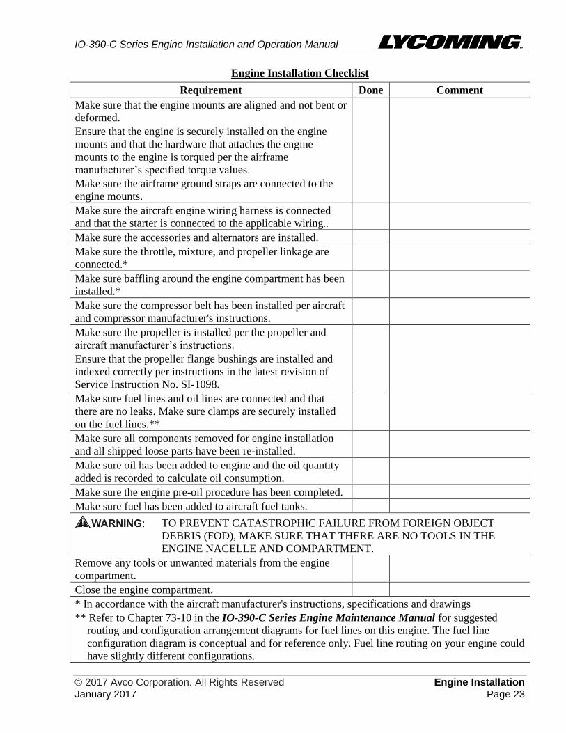
Engine Installation Checklist
Requirement Done Comment
Make sure that the engine mounts are aligned and not bent or
deformed.
Ensure that the engine is securely installed on the engine
mounts and that the hardware that attaches the engine
mounts to the engine is torqued per the airframe
manufacturer’s specified torque values.
Make sure the airframe ground straps are connected to the
engine mounts.
Make sure the aircraft engine wiring harness is connected
and that the starter is connected to the applicable wiring..
Make sure the accessories and alternators are installed.
Make sure the throttle, mixture, and propeller linkage are
connected.*
Make sure baffling around the engine compartment has been
installed.*
Make sure the compressor belt has been installed per aircraft
and compressor manufacturer's instructions.
Make sure the propeller is installed per the propeller and
aircraft manufacturer’s instructions.
Ensure that the propeller flange bushings are installed and
indexed correctly per instructions in the latest revision of
Service Instruction No. SI-1098.
Make sure fuel lines and oil lines are connected and that
there are no leaks. Make sure clamps are securely installed
on the fuel lines.**
Make sure all components removed for engine installation
and all shipped loose parts have been re-installed.
Make sure oil has been added to engine and the oil quantity
added is recorded to calculate oil consumption.
Make sure the engine pre-oil procedure has been completed.
Make sure fuel has been added to aircraft fuel tanks.
TO PREVENT CATASTROPHIC FAILURE FROM FOREIGN OBJECT
DEBRIS (FOD), MAKE SURE THAT THERE ARE NO TOOLS IN THE
ENGINE NACELLE AND COMPARTMENT.
Remove any tools or unwanted materials from the engine
compartment.
Close the engine compartment.
* In accordance with the aircraft manufacturer's instructions, specifications and drawings
** Refer to Chapter 73-10 in the IO-390-C Series Engine Maintenance Manual for suggested
routing and configuration arrangement diagrams for fuel lines on this engine. The fuel line
configuration diagram is conceptual and for reference only. Fuel line routing on your engine could
have slightly different configurations.

IO-390-C Series Engine Installation and Operation Manual
Engine Installation © 2017 Avco Corporation. All Rights Reserved Page 24 January 2017
This page intentionally left blank.

IO-390-C Series Engine Installation and Operation Manual
© 2017 Avco Corporation. All Rights Reserved Field Run-In January 2017 Page 25
FIELD RUN-IN
Either a field run-in or a factory run-in procedure is done to ensure that the engine meets all
specifications and is operating correctly. Since a run-in is done on new, rebuilt or overhauled
engines shipped from Lycoming Engines, the field run-in is not necessary. However, a field run-in
procedure herein is done only on engines in the field after any of the following:
A field-overhauled engine is installed
Field disassembly and reassembly of the engine for any repair, component replacement, or
inspection that requires separation of the crankcase halves
NOTICE: Refer to the latest revision of Service Instruction No. SI-1427 for any additional details
on the field run-in.
Field Run-In Procedure
Field run-in of fixed wing aircraft includes two procedures, “Preparation for Ground Operational
Test with Engine Installed in Aircraft” and “Ground Operational Test.”
1. Preparation for Ground Operational Test with Engine Installed in Aircraft
NOTICE: The engine pre-oil procedure in the “Engine Installation” chapter in this manual
must be already completed before the ground operational test can be done.
A. Ensure that all engine instrumentation is calibrated to ensure accuracy.
MAKE SURE THAT ALL VENT AND BREATHER LINES ARE
INSTALLED CORRECTLY AND ARE SECURELY IN PLACE IN
ACCORDANCE WITH THE AIRFRAME MAINTENANCE
MANUAL.
B. Install engine intercylinder baffles, airframe baffles/seals, and cowling. All baffles and
seals must be in new or good condition to ensure sufficient cooling airflow differential
across the engine.
C. For optimum cooling during the ground operational test, use a test club propeller. If a test
club is unavailable, a regular flight propeller can be used as long as cylinder head
temperatures are monitored closely.
2. Ground Operational Test
NOTICE: Before the ground operational test, the oil cooler system must not have any air locks.
A. Before the start of the ground operational test, examine the oil cooler, propeller, and
governor for metal contamination. These parts must be clean and free of contamination
before the ground operational test can begin. If the engine had failed before overhaul, the
oil cooler, propeller, and governor must be replaced or cleaned and examined by an
approved repair facility.
B. Put the aircraft in a position facing the wind.
C. Start the engine and look at the oil pressure gage. If sufficient oil pressure indication (per
Appendix A, Table A-2) is not shown within 30 seconds, stop the engine. Identify and
correct the cause.
IO-390-C Series Engine Installation and Operation Manual
Field Run-In © 2017 Avco Corporation. All Rights Reserved Page 26 January 2017
D. If oil pressure is sufficient, operate the engine at 1000 RPM until the oil temperature is
stable or is at 140°F (60°C). After warm-up, the oil pressure is not to be less than the
minimum specified pressure per Appendix A.
E. Increase the engine speed to 1500 RPM and operate the engine at that speed for 15
minutes.
F. Make sure the cylinder head temperature, oil temperature, and oil pressure are within the
specified limits in Appendix A of this manual.
NOTICE: Extended ground operation can cause excessively high cylinder head and/or oil
temperatures.
If any malfunction occurs, stop the engine and let it cool. Identify and correct the
cause before continuation of the ground operational test.
a) Start the engine again and monitor oil pressure.
b) Increase engine speed to 1500 RPM for 5 minutes.
G. Complete a magneto drop-off check during engine start per the “Engine Initiation”
chapter in this manual.
H. Complete a cycle of the propeller pitch and a feathering check as applicable per the
airframe manufacturer’s recommendations.
I. Operate the engine to full-static aircraft recommended power (in Appendix A) for up to
10 seconds.
J. After engine operation at full power, slowly decrease the RPM to idle and let the engine
stabilize.
NOTICE: As needed, set fuel controls on new, rebuilt, or overhauled engine to 50 to 100
rpm higher than usual idle speed (600 to 700 rpm) for the first 25 hours of
operation - then adjust to the usual setting after the first 25 hours of operation.
K. Complete a check of the idle mixture adjustment per the “Idle Speed and Mixture
Adjustment” procedure in Chapter 72-00 of the IO-390-C Series Engine Maintenance
Manual.
L. Shut down the engine per the “Engine Stop” procedure in the “Engine Initiation” chapter
of this manual.
M. After shutdown, examine the engine for oil and fuel leaks. Identify and correct the cause
of any leaks.
N. Per Chapter 12-10 in the IO-390-C Series Engine Maintenance Manual:
(1) Complete an oil change and replace the oil filter.
(2) Remove, clean, and install the oil suction screen.
(3) Add the correct grade and quantity of oil to the engine per the latest revision of
Service Instruction No. SI-1014 and Appendix A of this manual.
3. Proceed to the “Engine Initiation” chapter for the remaining procedures to put the engine into
service
IO-390-C Series Engine Installation and Operation Manual
© 2017 Avco Corporation. All Rights Reserved Engine Initiation January 2017 Page 27
ENGINE INITIATION
Engine Initiation
Engine initiation includes the procedures in Table 1 which are to be done in the field on any of the
following newly installed Lycoming engines:
Any new, overhauled, or rebuilt engine from the factory and field-overhauled engines
Engine taken out of storage (if not run-in when put in storage)
An engine which has been disassembled/re-assembled
NOTICE: All of the procedures in Table 1 are mandatory and must be done prior to the first flight
with the engine.
Table 1
Engine Initiation Procedures for All Lycoming Engines
(Except Engine Overhauled in the Field)
Step Section References in This Chapter
1 Pre-Flight Inspection for Engine Initiation
2 Engine Start
3 Engine Run-Up
4 Engine Stop
5 Break-In/Flight Test/50-Hour Operation*
6 Required Inspections During Break-In
Warranty Requirement
AS ONE OF THE CONDITIONS FOR THE ENGINE WARRANTY, YOU
MUST OPERATE THIS ENGINE IN ACCORDANCE WITH
SPECIFICATIONS IN THIS MANUAL. YOU ALSO MUST COMPLETE
THE RECOMMENDED SERVICE AND MAINTENANCE PROCEDURES IN
ACCORDANCE WITH THE IO-390-C SERIES ENGINE MAINTENANCE
MANUAL FOR THIS ENGINE.
Step 1. Pre-Flight Inspection for Engine Initiation
Copy and complete the Pre-Flight Inspection Checklist for Engine Initiation.

IO-390-C Series Engine Installation and Operation Manual
Engine Initiation © 2017 Avco Corporation. All Rights Reserved Page 28 January 2017
Pre-Flight Inspection Checklist for Engine Initiation
Engine Model Number___________________ Engine Serial Number:___________________
Engine Time:______________________ Date Inspection Done:________________________
Inspection done by:___________________________
Requirement Comments Done
Make sure that all switches are OFF.
Make sure the magneto P-leads are connected.
NOTICE: Refer to Appendix A for minimum quantity of oil in flight.
Per the “Oil Level Check” procedure in Chapter 12-10*,
measure the engine oil level before every flight to make
sure there is sufficient oil in the engine. If the oil level is
unexpectedly too low, look for any oil leaks. Identify and
correct the cause of any oil leak. There must not be any
oil leaks. Add the correct specified grade of oil as
necessary per the “Add Oil to the Engine” procedure in
Chapter 12-10.*.
NOTICE: During the first 50 hours of engine operation of a new, rebuilt, or overhauled engine, it
is recommended that this engine be operated with mineral oil until oil consumption has
stabilized.
The oil sump capacity and the minimum quantity for flight are identified in Appendix
A.
Make sure that the engine crankcase breather is attached
tightly and that there are no blockages to the breather air
flow.
Remove any blockage to the air
flow. Identify and correct the
cause of any blockage.
If the engine is newly installed or is to be put back into
service after long-term storage, make sure that the pre-oil
procedure was done.
Refer to Section "Step 12.
Engine Pre-Oil Procedure" in
the "Engine Installation"
chapter in this manual.
Make sure that the induction air filter is clean and
securely in place.
Examine the engine, propeller hub area, and cowl for
indication of fuel and engine oil leaks.
Identify and correct the cause of
any leaks.
Look in the engine compartment and cowling for any
FOD such as: unwanted material, tools, loose, missing
fittings, clamps and connections. Examine for restrictions
to cooling airflow. Remove any FOD.
Tighten any loose hardware or
connections per torque values
supplied by the aircraft
manufacturer.
* Refer to the IO-390-C Series Engine Maintenance Manual.
IO-390-C Series Engine Installation and Operation Manual
© 2017 Avco Corporation. All Rights Reserved Engine Initiation January 2017 Page 29
Pre-Flight Inspection Checklist for Engine Initiation (Cont.)
Requirement Comments Done
DO NOT ROUTE FUEL OR OIL LINES CLOSE TO HEAT SOURCES. HEAT
CAN DAMAGE THE FUEL AND OIL LINES AND CAUSE A LEAK WHICH
COULD LEAD TO CATASTROPHIC ENGINE FAILURE.
Examine fuel lines:
A. Make sure that each fuel and oil line is intact, not
bent or damaged, and does not have any kinks or
dents.
B. Make sure that the fuel and oil lines are securely
connected.
C. Make sure the clamps are tightly attached to
support the fuel and oil line and to prevent
movement from vibration or motion frequencies.
Do NOT use plastic tie straps in place of
cushioned clamps.
D. Do not let fuel or oil lines touch the engine or
aircraft baffle hardware. There must be a minimum
of clearance of 3/16 in. (4.76 mm) between a fuel
and oil line and any engine or aircraft surface.
Refer to Chapters 72-50 and 73-
10 in the IO-390-C Series
Engine Maintenance Manual.
NOTICE: Record any problems found and corrective action taken in the engine logbook. Record
the magnitude and duration of a problem and any out-of-tolerance values.
Correct all problems before engine start. Refer to the
"Engine Conditions" chapter in this manual.
Step 2. Engine Start
MAKE SURE THAT THE AREA AROUND THE PROPELLER IS CLEAR OF
PERSONNEL OR ANY OBSTRUCTION BEFORE STARTING THE
ENGINE. IF THE PROPELLER HITS AN OBJECT, DO NOT PROCEED
WITH FLIGHT. REFER TO THE LATEST REVISION OF SERVICE
BULLETIN NO. SB-533.
NOTICE: If the engine is to be started in an environment at temperatures less than +10°F (-12°C),
refer to the section “Apply Heat to a Cold Engine” in the “Engine Conditions” chapter
in this manual. If the engine is to be operated at temperatures over 90°F (32°C), refer to
the section “Engine Operation in Hot Weather” in the “Engine Conditions” chapter in
this manual.
The following is Lycoming Engine’s recommended start procedure. If there is any
variation between the start procedure in the aircraft manufacturer’s (Pilot’s Operating
Handbook (POH) and Lycoming Engine’s recommended start procedure, follow the
aircraft manufacturer’s procedure.
1. If the engine is newly installed or is to be put back into service after long-term storage, make
sure the pre-oil procedure was done. Refer to the section "Step 12. Complete the Engine Pre-
Oil Procedure" in the "Engine Installation" chapter in this manual.
IO-390-C Series Engine Installation and Operation Manual
Engine Initiation © 2017 Avco Corporation. All Rights Reserved Page 30 January 2017
2. Complete specified steps for engine start recommended by the aircraft POH, aircraft
manufacturer, or Supplemental Type Certificate (STC) holder’s instructions.
3. Examine the engine for hydraulic lock which is a condition where fluid accumulates in the
induction system or the cylinder assembly. Refer to Chapter 05-50 of the IO-390-C Series
Engine Maintenance Manual for details.
DO NOT OPERATE THE ENGINE IF HYDRAULIC LOCK IS POSSIBLE.
HYDRAULIC LOCK CAN CAUSE ENGINE DAMAGE. DO NOT
CONTINUE TO OPERATE A MALFUNCTIONING ENGINETO
PREVENT ADDITIONAL DAMAGE TO THE ENGINE, POSSIBLE
BODILY INJURY OR DEATH.
4. Refer to the aircraft POH for the engine start settings and start procedure.
5. Set the alternate air control to the OFF position.
6. Set the propeller governor to FULL RPM.
7. Turn the fuel valve ON in accordance with the aircraft POH.
8. Open the throttle approximately to 1/4 travel.
9. Turn the boost pump ON.
10. Move the mixture control to FULL RICH until a slight but steady flow is indicated.
11. Set the magneto select switch per the aircraft manufacturer's instructions.
NOTICE: For switch information, refer to the aircraft manufacturer's handbook.
DO NOT ENERGIZE THE STARTER FOR PERIODS OVER 10
SECONDS. LET THE STARTER COOL FOR 30 SECONDS AFTER
EACH ENERGIZATION. IF THE STARTER FAILS TO ENERGIZE
AFTER TWO ATTEMPTS, IDENTIFY AND CORRECT THE CAUSE. DO
NOT TRY MORE THAN FIVE ENGINE STARTS WITHIN A 2-MINUTE
PERIOD.
NOTICE: A low battery, engine speed less than 50 rpm, or sub-zero temperatures can prevent
engine start. Refer to the section "Apply Heat to a Cold Engine" in the "Engine
Conditions" chapter.
12. Energize the starter (not to exceed 10 seconds) until the engine starts.
13. Put the magneto switch in the BOTH position.
DO NOT EXCEED THE IDLE RPM (SET BY THE AIRCRAFT
MANUFACTURER) UNTIL THE OIL PRESSURE IS STABLE ABOVE
THE MINIMUM IDLING RANGE. IF THERE IS NO INDICATION OF
OIL PRESSURE WITHIN 10 SECONDS, STOP THE ENGINE. IDENTIFY
AND CORRECT THE CAUSE. REFER TO THE "ENGINE CONDITIONS"
CHAPTER IN THIS MANUAL.
DO NOT OPERATE THE ENGINE IF THE OIL PRESSURE IS LOW. IF
THE ENGINE IS OPERATED AT LOW OR NO OIL PRESSURE, THE
ENGINE CAN MALFUNCTION OR STOP.

IO-390-C Series Engine Installation and Operation Manual
© 2017 Avco Corporation. All Rights Reserved Engine Initiation January 2017 Page 31
14. Look at the oil pressure gage for indicated pressure. If there is no oil pressure indication
within 10 seconds, stop the engine. Identify and correct the problems.
NOTICE: Unstable oil pressure or oil pressure less than 25 psi (172 kPa) could be an
indication of obstructed or interrupted oil flow or air in the oil lines. In this case,
stop, identify and correct the cause.
COMPLETE SMOOTH AND STEADY THROTTLE MOVEMENTS. FULL
RANGE THROTTLE MOVEMENT IN LESS THAN 2 SECONDS IS TOO
RAPID AND CAN CAUSE DETUNED COUNTERWEIGHTS, FAILURE
OF THE COUNTERWEIGHT LOBES, AND SUBSEQUENT ENGINE
DAMAGE.
15. Move the throttle slowly and smoothly to the IDLE rpm.
NOTICE: The engine is warm enough for take-off when the throttle can be opened without the
engine faltering.
Upon engine start, if smoke comes from a newly installed engine, after the first start,
there could have been some preservative oil in the cylinders, induction system,
and/or fuel nozzles/lines. If oil pressure is normal and the engine operates smoothly,
continue to operate the engine until the smoke clears. Otherwise, stop the engine and
identify the cause.
16. Let the engine operate at 1000 rpm for approximately 3 minutes.
17. Look for any illuminated caution or warning lights in the cockpit.
Step 3. Engine Run-Up
IF DURING ENGINE RUN-UP OR ENGINE IDLE, ANY OPERATIONAL
PROBLEMS OCCUR, DO NOT TAKE-OFF. IDENTIFY AND CORRECT
THE CAUSE OF THE PROBLEM AND COMPLETE THE OPERATIONAL
TEST IN THE “FIELD RUN-IN” CHAPTER AGAIN.
Complete the engine run-up as follows:
1. Make sure the oil pressure is within the specified limits (Appendix A).
2. Complete a magneto drop-off check as follows:
Aircraft with fixed pitch propellers, or those that do not have a manifold pressure gage, can
complete magneto drop-off with the engine operating at approximately 2100 to 2200 RPM.
NOTICE: Full feathering check (twin engine) on the ground is not recommended but a
check of the feathering action can be done by operating the engine between 1000
to 1500 rpm, then momentarily pulling the propeller control into the feathering
position. Do not allow the rpm to drop more than 500 rpm.
For aircraft with variable pitch propellers that do have a manifold pressure gage:
(1) Move the propeller control through its complete range as a check for operation and
return to the full increase RPM position.
(2) With the propeller in full increase RPM position, set the engine to produce 50% to
65% power per the manifold pressure gage unless otherwise specified in the aircraft
manufacturer’s manual.
IO-390-C Series Engine Installation and Operation Manual
Engine Initiation © 2017 Avco Corporation. All Rights Reserved Page 32 January 2017
NOTICE: To prevent spark plug fouling, do not operate on a single magneto for too long a
period. A few seconds is usually sufficient for the magneto drop-off check.
A. Switch from BOTH magnetos to left magneto and record the drop-off; return to BOTH
until the engine regains speed and switch to the right magneto and record the drop-off,
then return to BOTH. Drop-off must not exceed 175 rpm and must not exceed 50 rpm
between magnetos.
B. If the rpm drop exceeds 175 rpm, slowly lean the mixture until the rpm peaks. Then
retard the throttle to the specified rpm, for the magneto drop-off check and repeat the
check. If the drop-off does not exceed 175 rpm and the difference between the drop-off
values for both magnetos does not exceed 50 rpm, and the engine is running smoothly,
the ignition system is operating properly.
C. Smooth operation of the engine with a drop-off that exceeds the specification of 175 rpm
is usually an indication of a propeller load condition at a rich mixture.
IF THE ENGINE IS OPERATED AT LOW OIL PRESSURE OR LOW OIL
LEVEL, THE ENGINE CAN MALFUNCTION OR STOP.
3. Make sure the oil pressure and oil temperatures are within the specified operating range in
Appendix A.
AVOID PROLONGED IDLING. DO NOT EXCEED 2200 RPM DURING
WARM-UP. THE ENGINE IS WARM ENOUGH FOR TAKE-OFF WHEN
THE THROTTLE CAN BE OPENED WITHOUT THE ENGINE
FALTERING.
4. For engines with a variable pitch propeller, increase the engine speed to approximately 2100
to 2200 RPM and cycle through the propeller pitch setting three times to ensure correct
propeller operation.
5. Move the throttle slowly and smoothly to the IDLE rpm.
Step 4. Engine Stop
1. Set the propeller at minimum blade angle.
2. Keep the engine speed between 1000 to 1200 rpm, until the operating temperatures are stable
and Exhaust Gas Temperature (EGT) (if applicable) is approximately 1100ºF (593ºC).
3. Move the mixture control to IDLE CUT-OFF.
4. After the engine stops, set the ignition switch to the OFF position.
5. Turn the fuel valve OFF in accordance with the aircraft POH.
DO NOT MANUALLY TURN THE PROPELLER ON A HOT ENGINE
EVEN THOUGH THE IGNITION SWITCH IS IN THE OFF POSITION.
THE ENGINE COULD KICK BACK AS A RESULT OF AUTO-IGNITION
CAUSED BY A SMALL AMOUNT OF FUEL REMAINING IN THE
CYLINDERS. AUTO-IGNITION COULD RESTART THE ENGINE AND
CAUSE SERIOUS BODILY INJURY OR DEATH.
6. Refer to the aircraft manufacturer's POH for additional information.
IO-390-C Series Engine Installation and Operation Manual
© 2017 Avco Corporation. All Rights Reserved Engine Initiation January 2017 Page 33
Step 5. Break-In/Flight Test/50-Hour Operation
Engine break-in is done to seat the piston rings and stabilize oil consumption. Break-in includes two
progressive procedures:
A flight test (done first)
Operating at specified cruise powers (per Appendix A) for 50 hours or until oil
consumption stabilizes.
NOTICE: Refer to the latest revision of Service Instruction No. SI-1427 for any additional details.
An operational test and a pre-flight ground run-up must be done before approval by an authorized
inspector for a flight test. This flight test, which is part of the required engine break-in field
procedure, is necessary to make sure that the engine and aircraft are in compliance with all of the
manufacturer’s performance and operational specifications before release of the aircraft for service.
REPLACE ENGINE TEST CLUBS WITH APPROVED FLIGHT PROPELLERS
BEFORE THE FLIGHT TEST.
DO NOT TAKE-OFF IF ANY OF THE FOLLOWING CONDITIONS ARE
FOUND:
Engine roughness High or low fuel flow
Low, high, or surging rpm or fluctuations High manifold pressure
High, low, or fluctuating oil pressure Low battery charge.
A. Start the engine and complete a pre-flight run-up in accordance with the applicable
manufacturer’s POH.
B. Complete a full power take-off in accordance with the POH.
C. Monitor the engine rpm, fuel flow, oil pressure, oil temperature and cylinder head
temperature during take-off.
D. As soon as possible, decrease to climb power in accordance with the POH.
E. Complete a shallow climb angle to a suitable cruise altitude.
F. Adjust the fuel/air mixture per the POH.
DURING BREAK-IN, MAKE SURE THE ENGINE IS OPERATED AT 65%
OR MORE CRUISE POWER AS MUCH AS PRACTICAL TO ENSURE
CORRECT PISTON RING SEATING. ENGINE OPERATION BELOW 65%
CRUISE POWER AT ANY TIME DURING BREAK-IN CAN RESULT IN
INADEQUATE SEATING OF THE PISTON RINGS.
NOTICE: For a normally aspirated (non-turbocharged) engine, operate the engine at cruise
power at the lower altitudes. Density altitude in excess of 8,000 feet (2438 m) will
prevent the engine from reaching sufficient cruise power for an acceptable break-in;
an altitude of 5,000 feet (1524 m) is recommended.
G. At cruise altitude, decrease power to approximately 75% and continue flight for 2 hours. For
the second hour, operate the engine at power settings alternating between 65% and 75%
power as per the applicable POH.
IO-390-C Series Engine Installation and Operation Manual
Engine Initiation © 2017 Avco Corporation. All Rights Reserved Page 34 January 2017
H. If the engine and aircraft are operating to specifications in Appendix A, increase engine
power to the maximum airframe recommended power and hold for 30 minutes.
FOR ENGINES THAT HAVE DYNAMIC COUNTERWEIGHT
ASSEMBLIES, DO NOT OPERATE AT LOW MANIFOLD PRESSURE
DURING HIGH ENGINE SPEEDS UNDER 15 IN. HG AND RAPID
CHANGES IN ENGINE SPEEDS. THESE CONDITIONS CAN CAUSE
DAMAGE TO THE COUNTERWEIGHTS, ROLLERS OR BUSHINGS,
AND CAUSE DETUNING.
DO NOT DO CLOSED THROTTLE DESCENTS WHICH CAN CAUSE
RING FLUTTER AND DAMAGE TO THE CYLINDERS AND PISTON
RINGS.
I. Decrease altitude at low cruise power and closely monitor the engine instruments. Do not do
long descents at low manifold pressure. Do not decrease altitude too rapidly. The engine
temperature could decrease too quickly.
J. After landing and shutdown, examine the engine for oil and fuel leaks. Identify and correct
the cause of any leaks.
K. Calculate oil consumption and compare the limits given in Appendix A.
0.006 x BHP x 4 ÷ 7.4 = Qt./Hr.
L. If the oil consumption value is above the limits in Appendix A, identify and correct the cause.
Complete this flight test again, up to and including this step before releasing the aircraft for
service.
M. Refer to the Chapter 12-10 of the IO-390-C Series Engines Maintenance Manual to
complete the “Oil Change Procedure” – drain the mineral oil and add new mineral oil up to
specified oil sump capacity in Appendix A. (Mineral oil is used since it is within the first 50
hours of engine operation of a new, rebuilt, or overhauled engine.)
N. Complete the inspections identified in the “Required Inspections” section in this chapter.
O. Correct any problems before releasing the engine back into service.
P. Continue to operate the engine at cruise power settings of 65% to 75% for 50 hours or until
oil consumption stabilizes.
Step 6. Required Inspections During Break-In (50-Hour Operation)
During the next 50 hours of flight, complete the following inspections per Chapter 05-20 in the IO-
390-C Series Engines Maintenance Manual:
Visual Inspection
10-Hour Initial Engine Inspection Checklist
25-Hour Engine Inspection Checklist
50-Hour Engine Inspection Checklist
IO-390-C Series Engine Installation and Operation Manual
© 2017 Avco Corporation. All Rights Reserved Engine Operation January 2017 Page 35
ENGINE OPERATION
The procedures in this chapter are for routine engine operation. The steps in Table 1 must be
completed in the order shown for engine operation during routine service
Table 1
Prerequisite Requirements for Engine Operation
Step Section References in This Chapter
1 Pre-Flight Check
2 Engine Start
3 Engine Run-Up
4 Engine Operation
5 Engine Stop
Step 1. Pre-Flight Check
Refer to the Pilot’s Operating Handbook (POH) and complete a Pre-Flight Check before starting the
engine.
NOTICE: Examine the air filters every other flight for dirt and be prepared to clean or replace
them if necessary.
If the aircraft is flown in dusty conditions, more frequent oil changes are recommended.
Install dust covers over openings in the cowling for additional protection. Refer to the
section “Volcanic Ash” in the “Engine Conditions” chapter in this manual.
Step 2. Engine Start
MAKE SURE THAT THE AREA AROUND THE PROPELLER IS CLEAR OF
PERSONNEL OR ANY OBSTRUCTION BEFORE STARTING THE
ENGINE. IF THE PROPELLER HITS AN OBJECT, DO NOT PROCEED
WITH FLIGHT. REFER TO THE LATEST REVISION OF SERVICE
BULLETIN NO. SB-533.
NOTICE: If the engine is to be started in an environment at temperatures less than +10°F (-12°C),
refer to the section “Apply Heat to a Cold Engine” in the “Engine Conditions” chapter
in this manual. If the engine is to be operated at temperatures over 90°F (32°C), refer to
“Engine Operation in Hot Weather” in the “Engine Conditions” chapter in this manual.
The following is Lycoming Engine’s recommended start procedure. If there is any
variation between the start procedure in the aircraft manufacturer’s POH and Lycoming
Engine’s recommended start procedure, follow the aircraft manufacturer’s POH
procedure.
1. Complete specified steps for engine start recommended by the aircraft POH, aircraft
manufacturer, or Supplemental Type Certificate (STC) holder’s instructions.
2. Examine the engine for hydraulic lock which is a condition where fluid accumulates in the
induction system or the cylinder assembly. Refer to Chapter 05-50 of the IO-390-C Series
Engine Maintenance Manual for details.
IO-390-C Series Engine Installation and Operation Manual
Engine Operation © 2017 Avco Corporation. All Rights Reserved Page 36 January 2017
DO NOT OPERATE THE ENGINE IF HYDRAULIC LOCK IS POSSIBLE.
HYDRAULIC LOCK CAN CAUSE ENGINE DAMAGE. DO NOT
CONTINUE TO OPERATE A MALFUNCTIONING ENGINETO
PREVENT ADDITIONAL DAMAGE TO THE ENGINE, POSSIBLE
BODILY INJURY OR DEATH.
3. Refer to the aircraft POH for the engine start settings and start procedure.
4. Set the alternate air control to the OFF position.
5. Set the propeller governor to FULL RPM.
6. Turn the fuel valve ON in accordance with the aircraft POH.
7. Open the throttle approximately to 1/4 travel.
8. Turn the boost pump ON.
9. Move the mixture control to FULL RICH until a slight but steady flow is indicated.
10. Set the magneto select switch per the aircraft manufacturer's instructions.
NOTICE: For switch information, refer to the aircraft manufacturer's handbook.
DO NOT ENERGIZE THE STARTER FOR PERIODS OVER 10
SECONDS. LET THE STARTER COOL FOR 30 SECONDS AFTER
EACH ENERGIZATION. IF THE STARTER FAILS TO ENERGIZE
AFTER TWO ATTEMPTS, IDENTIFY AND CORRECT THE CAUSE. DO
NOT TRY MORE THAN FIVE ENGINE STARTS WITHIN A 2-MINUTE
PERIOD.
NOTICE: A low battery, engine speed less than 50 rpm, or sub-zero temperatures can prevent
engine start. Refer to the section "Apply Heat to a Cold Engine" in the "Engine
Conditions" chapter.
11. Energize the starter (not to exceed 10 seconds) until the engine starts.
12. Put the magneto switch in the BOTH position.
DO NOT EXCEED THE IDLE RPM (SET BY THE AIRCRAFT
MANUFACTURER) UNTIL THE OIL PRESSURE IS STABLE ABOVE
THE MINIMUM IDLING RANGE. IF THERE IS NO INDICATION OF
OIL PRESSURE WITHIN 10 SECONDS, STOP THE ENGINE. IDENTIFY
AND CORRECT THE CAUSE. REFER TO THE "ENGINE CONDITIONS"
CHAPTER IN THIS MANUAL.
DO NOT OPERATE THE ENGINE IF THE OIL PRESSURE IS LOW. IF
THE ENGINE IS OPERATED AT LOW OR NO OIL PRESSURE, THE
ENGINE CAN MALFUNCTION OR STOP.
13. Look at the oil pressure gage for indicated pressure. If there is no oil pressure indication
within 10 seconds, stop the engine. Identify and correct the problems.
NOTICE: Unstable oil pressure or oil pressure less than 25 psi (172 kPa) could be an
indication of obstructed or interrupted oil flow or air in the oil lines. In this case,
stop, identify and correct the cause.
IO-390-C Series Engine Installation and Operation Manual
© 2017 Avco Corporation. All Rights Reserved Engine Operation January 2017 Page 37
COMPLETE SMOOTH AND STEADY THROTTLE MOVEMENTS. FULL
RANGE THROTTLE MOVEMENT IN LESS THAN 2 SECONDS IS TOO
RAPID AND CAN CAUSE DETUNED COUNTERWEIGHTS, FAILURE
OF THE COUNTERWEIGHT LOBES, AND SUBSEQUENT ENGINE
DAMAGE.
14. Move the throttle slowly and smoothly to the IDLE rpm.
NOTICE: The engine is warm enough for take-off when the throttle can be opened without the
engine faltering.
Upon engine start, if smoke comes from a newly installed engine, after the first start,
there could have been some preservative oil in the cylinders, induction system,
and/or fuel nozzles/lines. If oil pressure is normal and the engine operates smoothly,
continue to operate the engine until the smoke clears. Otherwise, stop the engine and
identify the cause.
15. Let the engine operate at 1000 rpm for approximately 3 minutes.
16. Look for any illuminated caution or warning lights in the cockpit.
Step 3. Engine Run-Up
IF DURING ENGINE RUN-UP OR ENGINE IDLE, ANY OPERATIONAL
PROBLEMS OCCUR, DO NOT TAKE-OFF. IDENTIFY AND CORRECT
THE CAUSE OF THE PROBLEM AND COMPLETE THE OPERATIONAL
TEST IN THE “FIELD RUN-IN” CHAPTER AGAIN.
Complete the engine run-up as follows:
1. Make sure the oil pressure is within the specified limits (Appendix A).
2. Complete a magneto drop-off check as follows:
Aircraft with fixed pitch propellers, or those that do not have a manifold pressure gage, can
complete magneto drop-off with the engine operating at approximately 2100 to 2200 RPM.
NOTICE: Full feathering check (twin engine) on the ground is not recommended but a
check of the feathering action can be done by operating the engine between 1000
to 1500 rpm, then momentarily pulling the propeller control into the feathering
position. Do not allow the rpm to drop more than 500 rpm.
For aircraft with variable pitch propellers that do have a manifold pressure gage:
(1) Move the propeller control through its complete range as a check for operation and
return to the full increase RPM position.
(2) With the propeller in full increase RPM position, set the engine to produce 50% to
65% power per the manifold pressure gage unless otherwise specified in the aircraft
manufacturer’s manual.
NOTICE: To prevent spark plug fouling, do not operate on a single magneto for too long a
period. A few seconds is usually sufficient for the magneto drop-off check.
A. Switch from BOTH magnetos to left magneto and record the drop-off; return to BOTH
until the engine regains speed and switch to the right magneto and record the drop-off,
then return to BOTH. Drop-off must not exceed 175 rpm and must not exceed 50 rpm
between magnetos.
IO-390-C Series Engine Installation and Operation Manual
Engine Operation © 2017 Avco Corporation. All Rights Reserved Page 38 January 2017
B. If the rpm drop exceeds 175 rpm, slowly lean the mixture until the rpm peaks. Then
retard the throttle to the specified rpm, for the magneto drop-off check and repeat the
check. If the drop-off does not exceed 175 rpm and the difference between the drop-off
values for both magnetos does not exceed 50 rpm, and the engine is running smoothly,
the ignition system is operating properly.
C. Smooth operation of the engine with a drop-off that exceeds the specification of 175 rpm
is usually an indication of a propeller load condition at a rich mixture.
IF THE ENGINE IS OPERATED AT LOW OIL PRESSURE OR LOW OIL
LEVEL, THE ENGINE CAN MALFUNCTION OR STOP.
3. Make sure the oil pressure and oil temperatures are within the specified operating range in
Appendix A.
AVOID PROLONGED IDLING. DO NOT EXCEED 2200 RPM DURING
WARM-UP. THE ENGINE IS WARM ENOUGH FOR TAKE-OFF WHEN
THE THROTTLE CAN BE OPENED WITHOUT THE ENGINE
FALTERING.
4. For engines with a variable pitch propeller, increase the engine speed to approximately 2100
to 2200 RPM and cycle through the propeller pitch setting three times to ensure correct
propeller operation.
5. Move the throttle slowly and smoothly to the IDLE rpm.
Step 4. Engine Operation
DO NOT TAKE-OFF IF ANY OF THE FOLLOWING CONDITIONS ARE
FOUND:
Engine roughness High or low fuel flow
Low, high, or surging rpm or fluctuations High manifold pressure
High, low, or fluctuating oil pressure Low battery charge.
1. Before take-off, monitor the oil pressure, oil temperature, and cylinder head temperature to
make sure all are within their operating ranges (as specified in Appendix A).
2. Keep the mixture control at FULL RICH.
3. Make sure that when take-off power is applied smoothly, oil pressure, fuel flow, manifold
pressure, and rpm remain stable.
NOTICE: After 25 hours of operation, change the oil. Examine the oil filter and screen. Refer
to Chapter 12-10 in the IO-390-C Series Engine Maintenance Manual.
4. Examine the air filters every other flight for dirt and be prepared to clean or replace them if
necessary.
5. If the aircraft is flown in dusty conditions, more frequent oil changes are recommended.
Install dust covers over openings in the cowling for additional protection. Refer to the section
“Volcanic Ash” in the “Engine Conditions” chapter in this manual.
IO-390-C Series Engine Installation and Operation Manual
© 2017 Avco Corporation. All Rights Reserved Engine Operation January 2017 Page 39
Operation in Flight
1. See the aircraft manufacturer's instructions for recommended power settings.
2. Until oil consumption has stabilized after the first 50 hours of flight, cruising is to be done at
not less than 65% power to ensure correct seating of the rings.
Fuel Mixture Leaning
For maximum service life, the Cylinder Head Temperature (CHT) must be maintained below
435ºF (224ºC) during performance cruise operation and below 400ºF (205ºC) for economy
cruise powers.
Manual leaning can be monitored by exhaust gas temperature indication (if equipped with an
EGT gage), fuel flow indication, and by observation of engine speed and/or airspeed.
NEVER EXCEED THE MAXIMUM RED LINE CHT LIMIT.
On engines with manual control, maintain mixture control in the FULL RICH position for
rated take-off, climb and maximum cruise powers (above approximately 75%). However,
during take-off from a high elevation airport or during climb, roughness or loss of power can
occur from over-richness. In such a case, adjust the mixture control only enough for smooth
operation - not for economy. Monitor instruments for temperature rise. Rough operation due
to over-rich fuel/air mixture is most likely to be encountered at altitudes above 5,000 feet
(1524 meters).
Always return the mixture to FULL RICH before increasing power settings.
Operate the engine at maximum power mixture for performance cruise powers and at best
economy mixture for economy cruise power; unless otherwise specified in the POH. Refer to
Appendix A.
NOTICE: During descent, it could be necessary to manually lean fuel-injected engines for
smooth operation.
Fuel Mixture Leaning Options
1. Leaning to EGT (Normally aspirated engines with fuel injectors or carburetors).
A. Maximum Power Cruise (approximately 75% power) - Never lean beyond 150ºF (66°C)
on rich side of peak EGT unless the aircraft operator's manual shows otherwise. Monitor
cylinder head temperatures.
B. Best Economy Cruise (approximately 75% power and below) - Operate at peak EGT.
2. Leaning to Flowmeter.
Lean to applicable fuel-flow tables or lean to indicator marked for correct fuel-flow for each
power setting.
3. Leaning with Manual Mixture (without flowmeter or EGT gage).
A. Maximum Power Cruise (approximately 75% power) - Lean to maximum rpm or
airspeed.
B. Best Economy Cruise (approximately 75% power and below).
(1) Slowly lean the mixture until engine operation becomes rough or a rapid decrease in
RPM or airspeed occurs.
(2) Slowly enrich the mixture until engine operation becomes smooth or most of the
RPM or airspeed is restored.

IO-390-C Series Engine Installation and Operation Manual
Engine Operation © 2017 Avco Corporation. All Rights Reserved Page 40 January 2017
Step 5. Engine Stop
1. After landing, set the propeller at minimum blade angle.
2. Keep the engine speed between 1000 to 1200 rpm, until the operating temperatures are stable
and EGT (if applicable) is approximately 1100ºF (593ºC).
3. Move the mixture control to IDLE CUT-OFF.
4. After the engine stops, set the ignition switch to the OFF position.
5. Turn the fuel valve OFF in accordance with the aircraft POH.
DO NOT MANUALLY TURN THE PROPELLER ON A HOT ENGINE
EVEN THOUGH THE IGNITION SWITCH IS IN THE OFF POSITION.
THE ENGINE COULD KICK BACK AS A RESULT OF AUTO-IGNITION
CAUSED BY A SMALL AMOUNT OF FUEL REMAINING IN THE
CYLINDERS. AUTO-IGNITION COULD RESTART THE ENGINE AND
CAUSE SERIOUS BODILY INJURY OR DEATH.
6. Refer to the aircraft manufacturer's POH for additional information.
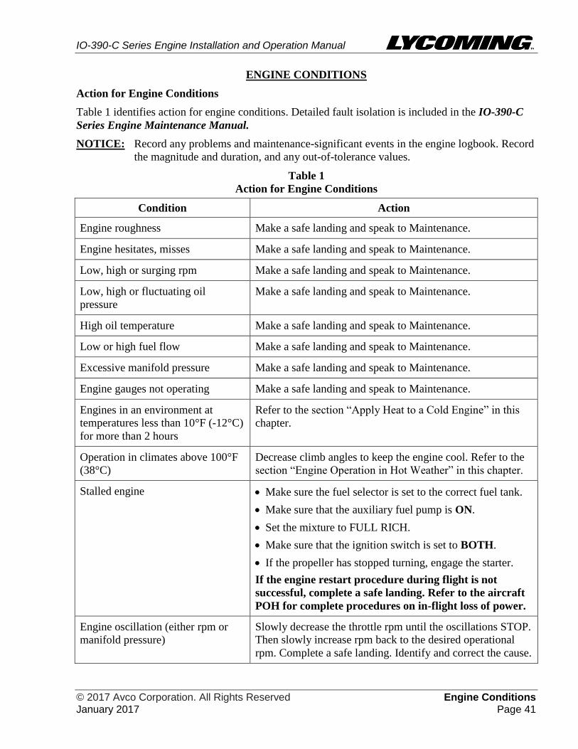
IO-390-C Series Engine Installation and Operation Manual
© 2017 Avco Corporation. All Rights Reserved Engine Conditions January 2017 Page 41
ENGINE CONDITIONS
Action for Engine Conditions
Table 1 identifies action for engine conditions. Detailed fault isolation is included in the IO-390-C
Series Engine Maintenance Manual.
NOTICE: Record any problems and maintenance-significant events in the engine logbook. Record
the magnitude and duration, and any out-of-tolerance values.
Table 1
Action for Engine Conditions
Condition Action
Engine roughness Make a safe landing and speak to Maintenance.
Engine hesitates, misses Make a safe landing and speak to Maintenance.
Low, high or surging rpm Make a safe landing and speak to Maintenance.
Low, high or fluctuating oil
pressure
Make a safe landing and speak to Maintenance.
High oil temperature Make a safe landing and speak to Maintenance.
Low or high fuel flow Make a safe landing and speak to Maintenance.
Excessive manifold pressure Make a safe landing and speak to Maintenance.
Engine gauges not operating Make a safe landing and speak to Maintenance.
Engines in an environment at
temperatures less than 10°F (-12°C)
for more than 2 hours
Refer to the section “Apply Heat to a Cold Engine” in this
chapter.
Operation in climates above 100°F
(38°C)
Decrease climb angles to keep the engine cool. Refer to the
section “Engine Operation in Hot Weather” in this chapter.
Stalled engine Make sure the fuel selector is set to the correct fuel tank.
Make sure that the auxiliary fuel pump is ON.
Set the mixture to FULL RICH.
Make sure that the ignition switch is set to BOTH.
If the propeller has stopped turning, engage the starter.
If the engine restart procedure during flight is not
successful, complete a safe landing. Refer to the aircraft
POH for complete procedures on in-flight loss of power.
Engine oscillation (either rpm or
manifold pressure)
Slowly decrease the throttle rpm until the oscillations STOP.
Then slowly increase rpm back to the desired operational
rpm. Complete a safe landing. Identify and correct the cause.
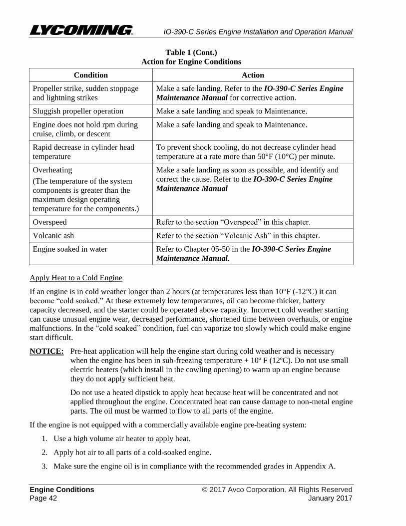
IO-390-C Series Engine Installation and Operation Manual
Engine Conditions © 2017 Avco Corporation. All Rights Reserved Page 42 January 2017
Table 1 (Cont.)
Action for Engine Conditions
Condition Action
Propeller strike, sudden stoppage
and lightning strikes
Make a safe landing. Refer to the IO-390-C Series Engine
Maintenance Manual for corrective action.
Sluggish propeller operation Make a safe landing and speak to Maintenance.
Engine does not hold rpm during
cruise, climb, or descent
Make a safe landing and speak to Maintenance.
Rapid decrease in cylinder head
temperature
To prevent shock cooling, do not decrease cylinder head
temperature at a rate more than 50°F (10°C) per minute.
Overheating
(The temperature of the system
components is greater than the
maximum design operating
temperature for the components.)
Make a safe landing as soon as possible, and identify and
correct the cause. Refer to the IO-390-C Series Engine
Maintenance Manual
Overspeed Refer to the section “Overspeed” in this chapter.
Volcanic ash Refer to the section “Volcanic Ash” in this chapter.
Engine soaked in water Refer to Chapter 05-50 in the IO-390-C Series Engine
Maintenance Manual.
Apply Heat to a Cold Engine
If an engine is in cold weather longer than 2 hours (at temperatures less than 10°F (-12°C) it can
become “cold soaked.” At these extremely low temperatures, oil can become thicker, battery
capacity decreased, and the starter could be operated above capacity. Incorrect cold weather starting
can cause unusual engine wear, decreased performance, shortened time between overhauls, or engine
malfunctions. In the “cold soaked” condition, fuel can vaporize too slowly which could make engine
start difficult.
NOTICE: Pre-heat application will help the engine start during cold weather and is necessary
when the engine has been in sub-freezing temperature + 10º F (12ºC). Do not use small
electric heaters (which install in the cowling opening) to warm up an engine because
they do not apply sufficient heat.
Do not use a heated dipstick to apply heat because heat will be concentrated and not
applied throughout the engine. Concentrated heat can cause damage to non-metal engine
parts. The oil must be warmed to flow to all parts of the engine.
If the engine is not equipped with a commercially available engine pre-heating system:
1. Use a high volume air heater to apply heat.
2. Apply hot air to all parts of a cold-soaked engine.
3. Make sure the engine oil is in compliance with the recommended grades in Appendix A.
IO-390-C Series Engine Installation and Operation Manual
© 2017 Avco Corporation. All Rights Reserved Engine Conditions January 2017 Page 43
IF HEAT HAS NOT BEEN APPLIED TO ALL PARTS OF THE ENGINE,
THE ENGINE CAN START AND RUN BUT LATER FAIL AFTER
APPLICATION OF HIGH POWER BECAUSE THE OIL WILL NOT
FLOW FULLY THROUGH THE ENGINE. DAMAGE CAN OCCUR AND
NOT BE KNOWN UNTIL AFTER SEVERAL HOURS OF OPERATION.
4. To ensure uniform heat application, apply hot air to the following parts in 5-minute intervals
for a minimum of 30 minutes:
Oil sump External oil lines Cylinder assemblies
Oil filter Oil cooler Air intake.
APPLY THE HOT AIR UNIFORMLY AND NOT CONCENTRATED IN
ONE SPOT TO PREVENT HEAT DAMAGE TO NON-METAL PARTS.
HEAT BUILD-UP CAN CAUSE DAMAGE TO WIRING, HOSES, ETC.
5. If cowl flaps are installed, open the cowl flaps to prevent heat build-up.
6. Between intervals, make sure the engine stays warm and keeps the heat. Make sure there is
no damage from heat build-up.
7. During the last 5 minutes of the heat process, apply heat to the top of the engine.
8. Start the engine immediately after the hot air application. Also, refer to additional engine start
information in the section “Cold Weather Start” in this chapter.
Cold Weather Engine Start
NOTICE: The following is Lycoming Engine’s recommended procedure for cold weather engine
starts. Refer to the aircraft manufacturer’s POH for in-flight recommendations during
cold weather.
1. After a cold start, do not rapidly increase acceleration or exceed the idle rpm. If oil pressure
indication is not shown within 10 seconds, stop the engine. Identify and correct the cause.
Allow up to 1 minute for oil pressure to become stable above 1000 rpm, since oil lines to the
gage can stay cold. If no leaks or damage are found, complete the pre-heat application again
before engine start.
2. Let the engine warm up at 1000 rpm until oil pressure and temperature are stable within
operating limits identified in Appendix A.
3. Complete a ground check in accordance with the aircraft manufacturer’s POH.
4. Complete a cycle of the propeller control position in accordance with the aircraft and
propeller manufacturer’s instructions to make sure warm oil is in the propeller dome.
5. Before take-off, monitor the oil pressure, oil temperature, and cylinder head temperature to
make sure all are within their operating ranges (as specified in Appendix A).
DO NOT TAKE-OFF IF ANY OF THE FOLLOWING CONDITIONS ARE
OBSERVED:
Engine roughness High or low fuel flow
Low, high or surging rpm or fluctuations High manifold pressure
High, low, or fluctuating oil pressure Low battery charge.
6. Make sure that when take-off power is applied smoothly, oil pressure, fuel flow, manifold
pressure, and rpm remain stable.

IO-390-C Series Engine Installation and Operation Manual
Engine Conditions © 2017 Avco Corporation. All Rights Reserved Page 44 January 2017
Engine Operation in Hot Weather
1. During engine operation in hot weather (temperatures above 90°F (32°C):
A. Monitor oil and cylinder temperatures as per Appendix A.
B. Operate the engine with cowl flaps fully open.
C. Do not operate the engine at maximum power any longer than necessary to make the
climb configuration recommended by the aircraft manufacturer.
D. Operate at sustained sufficient airspeed to cool off the engine.
Volcanic Ash
Given the dynamic conditions of volcanic ash, Lycoming’s recommendation is NOT to
operate the engine in areas where volcanic ash is present - in the air or on the ground. Refer
to the latest revision of Service Instruction No. SI-1530 for any new details.
Ash on the ground and runways can cause contamination in the engine compartment and
subsequent engine damage during aircraft landing or take-off.
Piston engines can be damaged by inlet air contaminated with volcanic ash. Solid deposits
from any number of sources can collect on engine baffles or other engine surfaces and
prevent engine cooling. Accumulation of deposits on the induction air filter can restrict or
block air flow to the engine and significantly decrease engine power. Contamination of
engine oil can cause engine malfunction and/or failure from abrasive wear.
Ash on the ground and runways can cause contamination of the engine compartment and
subsequent engine damage during aircraft landing or take-off.
In the event that flight through volcanic ash clouds or with ash on the ground and subsequent
contamination occurs, Lycoming Engines recommends the following standard actions:
1. Monitor the engine temperature during flight (damaged or blocked cooling baffles or
heavy deposits on engine cooling surfaces can decrease cooling efficiency and cause
engine overheating).
2. If the engine is not operating smoothly in flight, make a safe landing of the aircraft as
soon as possible and isolate faults on the engine.
DO NOT TOUCH THE VOLCANIC ASH WITH BARE HANDS. DO
NOT USE WATER TO REMOVE THE VOLCANIC ASH.
3. Additional measures could be necessary under specific operating conditions. Refer to the
IO-390-C Series Engine Maintenance Manual for corrective action.
Overspeed
In engine overspeed, the engine operates above its rated rpm speed (Appendix A). Operation
of an engine above its rated rpm can cause accelerated wear on already stressed components.
Momentary overspeed can occur during a landing attempt, when the propeller governor is in
a lag as the power control is suddenly opened for a go-around. In fixed wing aircraft,
momentary overspeed is an increase of no more than 10% of rated engine rpm for a period
not exceeding 3 seconds.

IO-390-C Series Engine Installation and Operation Manual
© 2017 Avco Corporation. All Rights Reserved Engine Conditions January 2017 Page 45
DO NOT OPERATE AN ENGINE CONTINUOUSLY IN AN OVERSPEED
CONDITION BECAUSE IT CAN WEAR OUT ENGINE PARTS AND
EVENTUALLY CAUSE ENGINE FAILURE.
Refer to the latest revision of Service Bulletin No. SB-369 for corrective action for engine
overspeed.
Record all incidents of engine overspeed in the engine logbook, along with the inspection and
any specified corrective action taken per Chapter 05-50 in the IO-390-C Series Engine
Maintenance Manual.
Low Oil Pressure During Flight
Circumstances which cause loss of oil pressure are many and varied. Therefore, it is difficult to
make a prediction of the extent of damage to the engine or its future reliability. In case of oil
pressure loss or engine operation with oil below the recommended minimum operating level
(identified in Table A-1 in Appendix A), the most conservative action is to remove and
disassemble the engine and completely examine all engine components per instructions in the
IO-390-C Series Engine Maintenance Manual.
NOTICE: Very often a sudden loss of oil pressure also shows a sudden increase in oil
temperature.
Any time oil pressure falls below the minimum level, complete a safe landing of the aircraft as
soon as possible. Identify the root cause according to the following protocol progressive steps
identified in Chapters 05-50 and 12-30 of the IO-390-C Series Engine Maintenance Manual.
NOTICE: Any decision to operate an engine that had a loss of oil pressure without an
inspection must be the responsibility of the agency who is putting the aircraft back
into service.

IO-390-C Series Engine Installation and Operation Manual
Engine Conditions © 2017 Avco Corporation. All Rights Reserved Page 46 January 2017
This page intentionally left blank.

IO-390-C Series Engine Installation and Operation Manual
© 2017 Avco Corporation. All Rights Reserved Engine Preservation and Storage January 2017 Page 47
ENGINE PRESERVATION AND STORAGE
Engine Corrosion and Prevention
Engines in aircraft that are not flown for at least 1 continuous hour within 30 days could be prone to
corrosion. Engine corrosion occurs when moisture from the air and products of combustion mix to
cause corrosion on cylinder walls and bearing surfaces when the aircraft is not used.
Corrosion rates can increase because of variable factors such as environmental conditions (humidity,
salt air in ocean areas), seasonal changes, and engine usage.
Since conditions can change, the corrosion rate can change. Aircraft operated close to oceans, lakes,
and rivers and in humid regions have a greater need for engine preservation than engines operated in
arid regions. In regions of high humidity, corrosion can be found on cylinder walls of new
inoperative engines in as little as 2 days.
The best way to decrease the risk of engine corrosion is for the aircraft to be in flight at least
every 30 days for at least 1 continuous hour at oil temperatures between 180°F to 200°F (80°C
to 93°C), depending on location and storage conditions. This continuous 1 hour of operation does
not include taxi, take-off and landing time. If the engine cannot be operated at the recommended oil
temperatures, speak with the aircraft manufacturer about the use of oil cooler winterization plates.
Because climate conditions are different in various geographic areas, Lycoming Engines only can
give general recommendations for corrosion prevention. The owner and operator must take into
account the following factors for setting a rust and corrosion prevention maintenance schedule for
the engine:
Environmental conditions, especially humidity Frequency of flight
Salt spray from the ocean Duration of flights
Size of the oil cooler system for the engine and airframe installation. (If the oil cooler system
is not the correct size, it can cause the engine to overheat or operate below the minimum
temperatures.) Low temperature operation can cause a build-up of water and acids
For operation at the correct temperature:
Make sure the aircraft temperature gages are correct.
Examine the condition of cooling air baffles. There must not be any blockage.
Make sure the baffles are the correct fit for maximum cooling air flow.
Complete oil and oil filter changes per the recommended intervals per Chapter 12-10 in the
IO-390-C Series Engine Maintenance Manual
Examine the cylinders for corrosion in engines that are stored in humid conditions and/or in
flight less than once a week.
Lycoming Engines’ recommends compliance with the engine preservation guidelines herein. Active
aircraft are flown at least 1 continuous hour at least once within 30 days. Stored aircraft are not in
flight for 31 to 60 days.

IO-390-C Series Engine Installation and Operation Manual
Engine Preservation and Storage © 2017 Avco Corporation. All Rights Reserved Page 48 January 2017
Engine Preservation Guidelines - 31 to 60 Days
The main emphasis in engine preservation is to decrease the risk of corrosion of engine parts which
can decrease engine service life. The engine cylinders, piston rings, valves, valve guides, camshaft,
and lifters are of primary concern with regards to corrosion prevention. Corrosion prevention uses
rust inhibitive compounds applied to vulnerable surfaces to prevent corrosion.
DO NOT MANUALLY (HAND) OPERATE THE PROPELLER TO
LUBRICATE THE ENGINE CYLINDERS. LUBRICATION IS INEFFICIENT
WITH MANUAL OPERATION AND CAN CAUSE PREMATURE WEAR OF
ENGINE PARTS FROM SCUFFING AND SPALLING.
Engine preservation is necessary, especially for engines that are not operated at least for 1
continuous hour every 30 consecutive days. If you know that an aircraft will not be operated for a
minimum of 30 days, then you must follow this procedure.
NOTICE: Ground operation of the engine for brief periods of time is not a substitute for hour-long
continuous engine flight. Short ground operation can make corrosive conditions worse.
The engine preservation procedure includes a spray application of preservative oil to the walls of
each engine cylinder.
You will need the following to complete this procedure:
Engine preservation oil mixture made up of 24% MIL-C-6529, 71% SAE J1966 Grade 1065
or MIL-PRF-21260 Grade 30, 5% Cortec M-529)
Airless spray gun or garden sprayer
Clay desiccant bags
NOTICE: Recommend starting this preservation procedure at the end of the last flight before
putting the engine into storage.
For engines installed in aircraft stored for 31 to 60 days:
1. Operate the engine until it is at the specified operating temperature in Appendix A. If
temperatures are below freezing, the oil temperature must be at least 165ºF (74ºC) before the
engine is stopped in the next step.
2. Stop the engine.
3. Refer to Chapter 12-10 in the IO-390-C Series Engine Maintenance Manual to complete
the following steps:
A. Drain the lubricating oil from the sump or system.
B. Clean the oil suction screen plug with mineral spirits, MIL-PRF-680, or equivalent
degreaser solvent.
C. Apply Food Grade AA Anti-Seize compound to the oil suction screen plug and install the
oil suction screen and plug with a new gasket. (Do not flare the ends of the suction
screen) Tighten the plug on the oil suction screen until the sealing surfaces are in contact.
Tighten this plug an additional 135º.
D. Apply one to two drops of Loctite® 564 to the threads of the oil sump drain plug.
E. Install, torque, and safety cable/wire the oil sump drain plug and oil suction screen plug
in accordance with the standard practices per the latest revision of AC43.13 or the latest
revision of the Service Table of Limits - SSP-1776 and the latest revision of Service
Instruction No. SI-1566.
IO-390-C Series Engine Installation and Operation Manual
© 2017 Avco Corporation. All Rights Reserved Engine Preservation and Storage January 2017 Page 49
4. Fill the sprayer with the preservative oil mixture.
5. Fill the oil sump with the specified preservative oil mixture up to the quantity of oil sump
capacity in Table A-1 in Appendix A.
6. Operate the engine until it is at the specified operating temperature. If temperatures are below
freezing, the oil temperature must be at least 165ºF (74ºC) before the engine is stopped in the
next step.
7. Stop the engine.
8. While the engine is still hot, immediately remove sufficient cowling to access the spark
plugs.
9. Remove either the top or bottom spark plug from each cylinder (per the “Spark Plug
Removal” procedure in Chapter 74-20 in the IO-390-C Series Engine Maintenance
Manual.)
10. Put the sprayer nozzle in the open spark plug hole on each cylinder.
11. Use the sprayer to apply a coat of approximately 2 oz. (60 ml) of the preservative oil mixture
through the spark plug hole on the interior wall of each cylinder.
DO NOT TURN THE CRANKSHAFT AFTER SPRAYING THE
CYLINDERS WITH PRESERVATIVE OIL.
12. After spray application is complete, remove the sprayer from the spark plug hole.
13. Install either the spark plugs (or cylinder dehydrator plugs MA-27512-2 or equivalent) if the
aircraft is kept in a region that has high humidity or near a sea coast.
NOTICE: Cylinder dehydrator plugs are recommended to be installed in place of spark plugs
because the dehydrator plugs provide moisture indication.
14. While the engine is still warm:
A. Remove the exhaust system and intake pipes per instructions in the IO-390-C Series
Engine Maintenance Manual.
B. Install bags of clay desiccant in the exhaust and intake ports.
C. Install the exhaust system and intake pipes per instructions in the IO-390-C Series
Engine Maintenance Manual.
D. Attach red cloth streamers to the desiccant as a reminder for the material to be removed
when the engine is ready for flight.
E. Use moisture-proof material and pressure sensitive tape to seal these openings:
Exhaust ports Vacant accessory pads
Intake ports All openings that connect the inside of the engine to the outside
atmosphere Breather
F. Put a note on the propeller that reads: "Engine preserved - DO NOT TURN THE
PROPELLER."
IO-390-C Series Engine Installation and Operation Manual
Engine Preservation and Storage © 2017 Avco Corporation. All Rights Reserved Page 50 January 2017
G. At 15-day intervals, examine the clay desiccant in the desiccant bags and the cylinder
dehydrator plugs (if installed). When the color of the desiccant has changed from blue to
pink, remove the used clay desiccant bags and plugs. Install new clay desiccant bags and
cylinder dehydrator plugs (if used). Record the date (for future reference) when the
desiccant bags and/or plugs were installed.
H. To return the engine to service after preservation, refer to the “Prepare a Stored Engine
for Installation” section in the “Requirements for Engine Installation” Chapter of this
manual.
Fuel Injector Preservation
Refer to the fuel injector manufacturer's instructions for preservation of fuel injectors.
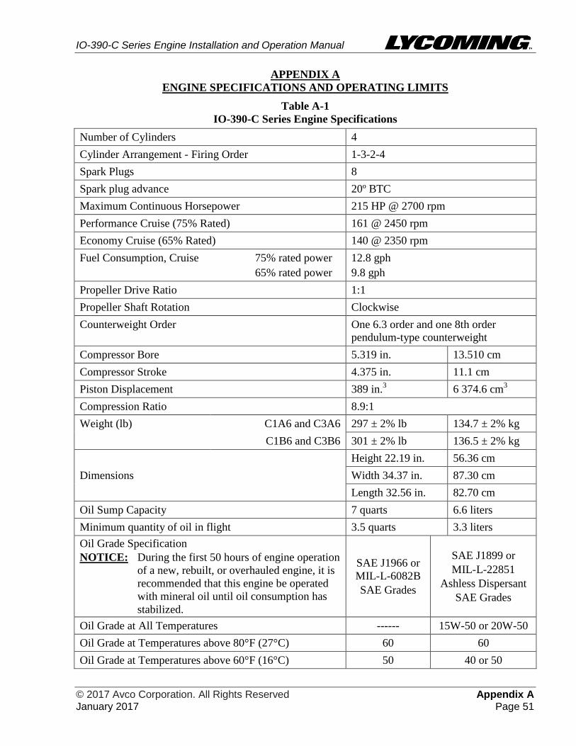
IO-390-C Series Engine Installation and Operation Manual
© 2017 Avco Corporation. All Rights Reserved Appendix A January 2017 Page 51
APPENDIX A
ENGINE SPECIFICATIONS AND OPERATING LIMITS
Table A-1
IO-390-C Series Engine Specifications
Number of Cylinders 4
Cylinder Arrangement - Firing Order 1-3-2-4
Spark Plugs 8
Spark plug advance 20º BTC
Maximum Continuous Horsepower 215 HP @ 2700 rpm
Performance Cruise (75% Rated) 161 @ 2450 rpm
Economy Cruise (65% Rated) 140 @ 2350 rpm
Fuel Consumption, Cruise 75% rated power
65% rated power
12.8 gph
9.8 gph
Propeller Drive Ratio 1:1
Propeller Shaft Rotation Clockwise
Counterweight Order One 6.3 order and one 8th order
pendulum-type counterweight
Compressor Bore 5.319 in. 13.510 cm
Compressor Stroke 4.375 in. 11.1 cm
Piston Displacement 389 in.3 6 374.6 cm
3
Compression Ratio 8.9:1
Weight (lb) C1A6 and C3A6 297 ± 2% lb 134.7 ± 2% kg
C1B6 and C3B6 301 ± 2% lb 136.5 ± 2% kg
Dimensions
Height 22.19 in. 56.36 cm
Width 34.37 in. 87.30 cm
Length 32.56 in. 82.70 cm
Oil Sump Capacity 7 quarts 6.6 liters
Minimum quantity of oil in flight 3.5 quarts 3.3 liters
Oil Grade Specification
NOTICE: During the first 50 hours of engine operation
of a new, rebuilt, or overhauled engine, it is
recommended that this engine be operated
with mineral oil until oil consumption has
stabilized.
SAE J1966 or
MIL-L-6082B
SAE Grades
SAE J1899 or
MIL-L-22851
Ashless Dispersant
SAE Grades
Oil Grade at All Temperatures ------ 15W-50 or 20W-50
Oil Grade at Temperatures above 80°F (27°C) 60 60
Oil Grade at Temperatures above 60°F (16°C) 50 40 or 50
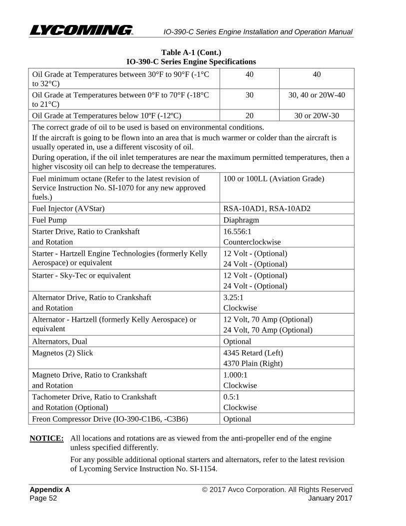
IO-390-C Series Engine Installation and Operation Manual
Appendix A © 2017 Avco Corporation. All Rights Reserved Page 52 January 2017
Table A-1 (Cont.)
IO-390-C Series Engine Specifications
Oil Grade at Temperatures between 30°F to 90°F (-1°C
to 32°C)
40 40
Oil Grade at Temperatures between 0°F to 70°F (-18°C
to 21°C)
30 30, 40 or 20W-40
Oil Grade at Temperatures below 10ºF (-12ºC) 20 30 or 20W-30
The correct grade of oil to be used is based on environmental conditions.
If the aircraft is going to be flown into an area that is much warmer or colder than the aircraft is
usually operated in, use a different viscosity of oil.
During operation, if the oil inlet temperatures are near the maximum permitted temperatures, then a
higher viscosity oil can help to decrease the temperatures.
Fuel minimum octane (Refer to the latest revision of
Service Instruction No. SI-1070 for any new approved
fuels.)
100 or 100LL (Aviation Grade)
Fuel Injector (AVStar) RSA-10AD1, RSA-10AD2
Fuel Pump Diaphragm
Starter Drive, Ratio to Crankshaft
and Rotation
16.556:1
Counterclockwise
Starter - Hartzell Engine Technologies (formerly Kelly
Aerospace) or equivalent
12 Volt - (Optional)
24 Volt - (Optional)
Starter - Sky-Tec or equivalent 12 Volt - (Optional)
24 Volt - (Optional)
Alternator Drive, Ratio to Crankshaft
and Rotation
3.25:1
Clockwise
Alternator - Hartzell (formerly Kelly Aerospace) or
equivalent
12 Volt, 70 Amp (Optional)
24 Volt, 70 Amp (Optional)
Alternators, Dual Optional
Magnetos (2) Slick
4345 Retard (Left)
4370 Plain (Right)
Magneto Drive, Ratio to Crankshaft
and Rotation
1.000:1
Clockwise
Tachometer Drive, Ratio to Crankshaft
and Rotation (Optional)
0.5:1
Clockwise
Freon Compressor Drive (IO-390-C1B6, -C3B6) Optional
NOTICE: All locations and rotations are as viewed from the anti-propeller end of the engine
unless specified differently.
For any possible additional optional starters and alternators, refer to the latest revision
of Lycoming Service Instruction No. SI-1154.
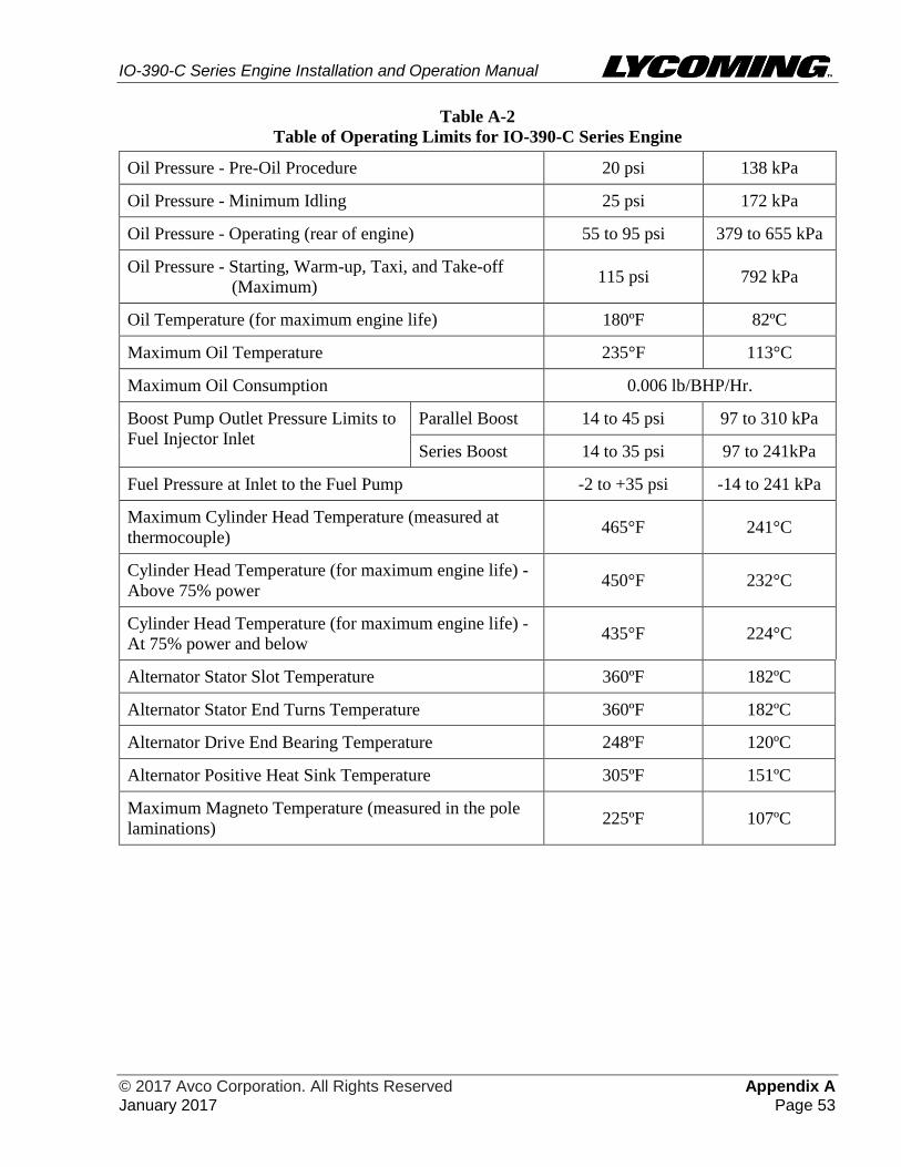
IO-390-C Series Engine Installation and Operation Manual
© 2017 Avco Corporation. All Rights Reserved Appendix A January 2017 Page 53
Table A-2
Table of Operating Limits for IO-390-C Series Engine
Oil Pressure - Pre-Oil Procedure 20 psi 138 kPa
Oil Pressure - Minimum Idling 25 psi 172 kPa
Oil Pressure - Operating (rear of engine) 55 to 95 psi 379 to 655 kPa
Oil Pressure - Starting, Warm-up, Taxi, and Take-off
(Maximum) 115 psi 792 kPa
Oil Temperature (for maximum engine life) 180ºF 82ºC
Maximum Oil Temperature 235°F 113°C
Maximum Oil Consumption 0.006 lb/BHP/Hr.
Boost Pump Outlet Pressure Limits to
Fuel Injector Inlet
Parallel Boost 14 to 45 psi 97 to 310 kPa
Series Boost 14 to 35 psi 97 to 241kPa
Fuel Pressure at Inlet to the Fuel Pump -2 to +35 psi -14 to 241 kPa
Maximum Cylinder Head Temperature (measured at
thermocouple) 465°F 241°C
Cylinder Head Temperature (for maximum engine life) -
Above 75% power 450°F 232°C
Cylinder Head Temperature (for maximum engine life) -
At 75% power and below 435°F 224°C
Alternator Stator Slot Temperature 360ºF 182ºC
Alternator Stator End Turns Temperature 360ºF 182ºC
Alternator Drive End Bearing Temperature 248ºF 120ºC
Alternator Positive Heat Sink Temperature 305ºF 151ºC
Maximum Magneto Temperature (measured in the pole
laminations) 225ºF 107ºC
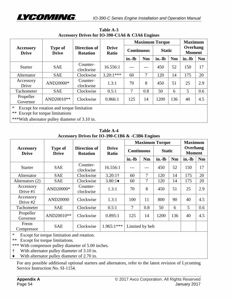
IO-390-C Series Engine Installation and Operation Manual
Appendix A © 2017 Avco Corporation. All Rights Reserved Page 54 January 2017
Table A-3
Accessory Drives for IO-390-C1A6 & C3A6 Engines
Accessory
Drive
Type of
Drive
Direction of
Rotation
Drive
Ratio
Maximum Torque Maximum
Overhang
Moment Continuous Static
in.-lb Nm in.-lb Nm in.-lb Nm
Starter SAE Counter-
clockwise 16.556:1 --- --- 450 52 150 17
Alternator SAE Clockwise 3.20:1*** 60 7 120 14 175 20
Accessory
Drive AND20000*
Counter-
clockwise 1.3:1 70 8 450 51 25 2.9
Tachometer SAE Clockwise 0.5:1 7 0.8 50 6 5 0.6
Propeller
Governor AND20010** Clockwise 0.866:1 125 14 1200 136 40 4.5
* Except for rotation and torque limitation
** Except for torque limitations
***With alternator pulley diameter of 3.10 in.
Table A-4
Accessory Drives for IO-390-C1B6 & -C3B6 Engines
Accessory
Drive
Type of
Drive
Direction of
Rotation
Drive
Ratio
Maximum Torque Maximum
Overhang
Moment Continuous Static
in.-lb Nm in.-lb Nm in.-lb Nm
Starter SAE Counter-
clockwise 16.556:1 --- --- 450 52 150 17
Alternator SAE Clockwise 3.20:1† 60 7 120 14 175 20
Alternators (2) SAE Clockwise 3.80:1♦ 60 7 120 14 175 20
Accessory
Drive #1 AND20000*
Counter-
clockwise 1.3:1 70 8 450 51 25 2.9
Accessory
Drive #2 AND20000 Clockwise 1.3:1 100 11 800 90 40 4.5
Tachometer SAE Clockwise 0.5:1 7 0.8 50 6 5 0.6
Propeller
Governor AND20010** Clockwise 0.895:1 125 14 1200 136 40 4.5
Freon
Compressor SAE Clockwise 1.965:1*** Limited by belt
* Except for torque limitation and rotation.
** Except for torque limitations.
*** With compressor pulley diameter of 5.00 inches.
† With alternator pulley diameter of 3.10 in.
♦ With alternator pulley diameter of 2.70 in.
For any possible additional optional starters and alternators, refer to the latest revision of Lycoming
Service Instruction No. SI-1154.

IO-390-C Series Engine Installation and Operation Manual
© 2017 Avco Corporation. All Rights Reserved Appendix B January 2017 Page 55
APPENDIX B
INSTALLATION DRAWINGS
NOTICE: Installation drawings in Table B-1 for respective engine models available from
Lycoming Engines for an IO-390-C series engine.
Table B-1
Installation Drawings for IO-390-C Series Engines
DRAWING NUMBER ENGINE MODEL
04J63637 IO-390-C1A6 AND C3A6
04J63634 IO-390-C1B6 AND C3B6
IO-390-C Series Engine Installation and Operation Manual
Appendix B © 2017 Avco Corporation. All Rights Reserved Page 56 January 2017
This page intentionally left blank.
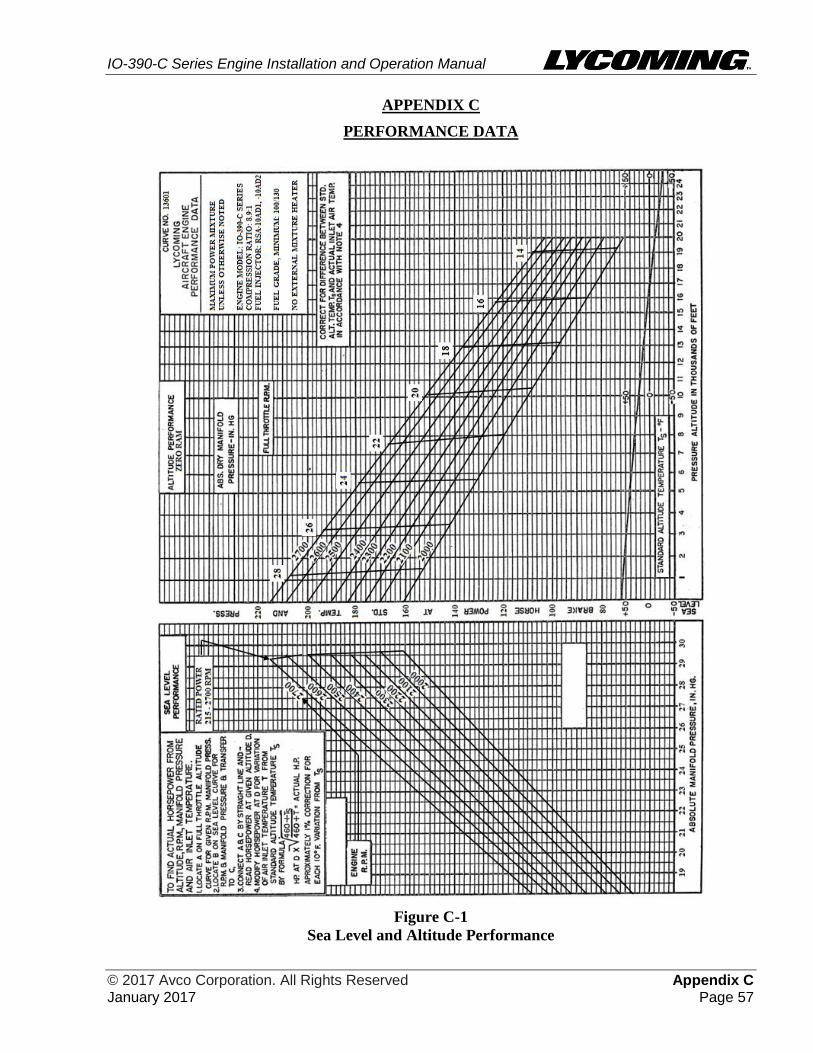
IO-390-C Series Engine Installation and Operation Manual
© 2017 Avco Corporation. All Rights Reserved Appendix C January 2017 Page 57
APPENDIX C
PERFORMANCE DATA
Figure C-1
Sea Level and Altitude Performance
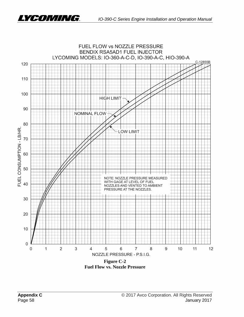
IO-390-C Series Engine Installation and Operation Manual
Appendix C © 2017 Avco Corporation. All Rights Reserved Page 58 January 2017
Figure C-2
Fuel Flow vs. Nozzle Pressure
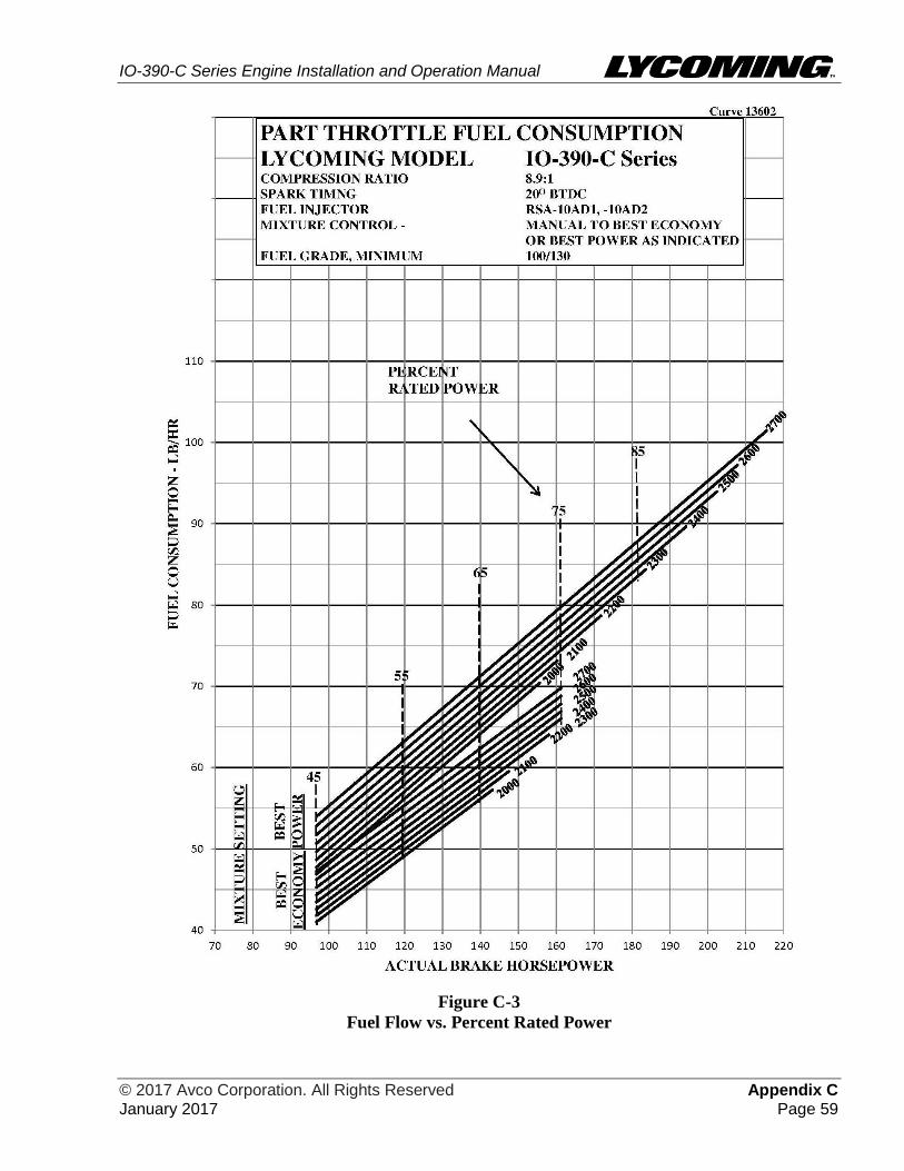
IO-390-C Series Engine Installation and Operation Manual
© 2017 Avco Corporation. All Rights Reserved Appendix C January 2017 Page 59
Figure C-3
Fuel Flow vs. Percent Rated Power
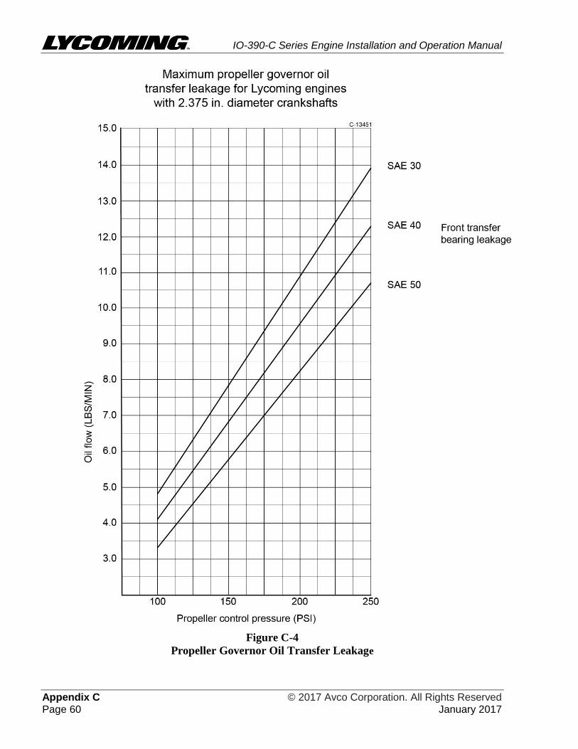
IO-390-C Series Engine Installation and Operation Manual
Appendix C © 2017 Avco Corporation. All Rights Reserved Page 60 January 2017
Figure C-4
Propeller Governor Oil Transfer Leakage
Related Documents