ENGINE CONTROL SYSTEM SECTION EC CONTENTS QG16I18DE TROUBLE DIAGNOSIS - INDEX ....................................6 Alphabetical & P No. Index for DTC ...........................6 PRECAUTIONS ...............................................................9 Supplemental Restraint System (SRS) ″AIR BAG″ and ″SEAT BELT PRE-TENSIONER″ ...............9 Precautions for On Board Diagnostic (OBD) System of Engine ........................................................9 Engine Fuel & Emission Control System ..................10 Precautions ................................................................ 11 Wiring Diagrams and Trouble Diagnosis ...................12 PREPARATION ..............................................................13 Special Service Tools ................................................13 Commercial Service Tool ...........................................13 ENGINE AND EMISSION CONTROL OVERALL SYSTEM.........................................................................14 Engine Control Component Parts Location ...............14 Circuit Diagram ..........................................................17 System Diagram ........................................................18 Vacuum Hose Drawing ..............................................19 System Chart .............................................................20 ENGINE AND EMISSION BASIC CONTROL SYSTEM DESCRIPTION ...............................................21 Multiport Fuel Injection (MFI) System .......................21 Electronic Ignition (EI) System ..................................23 Air Conditioning Cut Control ......................................24 Fuel Cut Control (at no load & high engine speed) ........................................................................25 Evaporative Emission System ...................................25 Positive Crankcase Ventilation ..................................28 BASIC SERVICE PROCEDURE ...................................29 Fuel Pressure Release ..............................................29 Fuel Pressure Check .................................................29 Fuel Pressure Regulator Check ................................30 Injector .......................................................................30 Idle Speed/Ignition Timing/Idle Mixture Ratio Adjustment .................................................................32 Idle Air Volume Learning ...........................................33 ON BOARD DIAGNOSTIC SYSTEM DESCRIPTION ...............................................................36 Introduction ................................................................36 Two Trip Detection Logic ...........................................36 Emission-related Diagnostic Information ...................37 Malfunction Indicator (MI) ..........................................45 OBD System Operation Chart ...................................50 CONSULT-II ...............................................................55 Generic Scan Tool (GST) ..........................................66 TROUBLE DIAGNOSIS - INTRODUCTION..................68 Introduction ................................................................68 Work Flow ..................................................................70 TROUBLE DIAGNOSIS - BASIC INSPECTION...........72 Basic Inspection.........................................................72 TROUBLE DIAGNOSIS - GENERAL DESCRIPTION ...............................................................80 DTC Inspection Priority Chart....................................80 Fail-safe Chart ...........................................................81 Symptom Matrix Chart ...............................................82 CONSULT-II Reference Value in Data Monitor Mode ..........................................................................86 Major Sensor Reference Graph in Data Monitor Mode ..........................................................................88 ECM Terminals and Reference Value .......................91 TROUBLE DIAGNOSIS - SPECIFICATION VALUE ....98 Description .................................................................98 Testing Condition .......................................................98 Inspection Procedure .................................................98 Diagnostic Procedure ................................................99 TROUBLE DIAGNOSIS FOR INTERMITTENT INCIDENT.....................................................................102 Description ...............................................................102 Diagnostic Procedure ..............................................102 TROUBLE DIAGNOSIS FOR POWER SUPPLY ........103 Main Power Supply and Ground Circuit ..................103 EC

Welcome message from author
This document is posted to help you gain knowledge. Please leave a comment to let me know what you think about it! Share it to your friends and learn new things together.
Transcript
ENGINE CONTROL SYSTEM
SECTIONECCONTENTS
QG16I18DE
TROUBLE DIAGNOSIS - INDEX ....................................6Alphabetical & P No. Index for DTC ...........................6
PRECAUTIONS ...............................................................9Supplemental Restraint System (SRS) ″AIRBAG″ and ″SEAT BELT PRE-TENSIONER″...............9Precautions for On Board Diagnostic (OBD)System of Engine ........................................................9Engine Fuel & Emission Control System ..................10Precautions ................................................................11Wiring Diagrams and Trouble Diagnosis...................12
PREPARATION ..............................................................13Special Service Tools ................................................13Commercial Service Tool...........................................13
ENGINE AND EMISSION CONTROL OVERALLSYSTEM.........................................................................14
Engine Control Component Parts Location...............14Circuit Diagram..........................................................17System Diagram ........................................................18Vacuum Hose Drawing ..............................................19System Chart .............................................................20
ENGINE AND EMISSION BASIC CONTROLSYSTEM DESCRIPTION ...............................................21
Multiport Fuel Injection (MFI) System .......................21Electronic Ignition (EI) System ..................................23Air Conditioning Cut Control......................................24Fuel Cut Control (at no load & high enginespeed) ........................................................................25Evaporative Emission System...................................25Positive Crankcase Ventilation ..................................28
BASIC SERVICE PROCEDURE ...................................29Fuel Pressure Release ..............................................29Fuel Pressure Check .................................................29Fuel Pressure Regulator Check ................................30Injector .......................................................................30Idle Speed/Ignition Timing/Idle Mixture RatioAdjustment .................................................................32
Idle Air Volume Learning ...........................................33ON BOARD DIAGNOSTIC SYSTEMDESCRIPTION ...............................................................36
Introduction ................................................................36Two Trip Detection Logic ...........................................36Emission-related Diagnostic Information ...................37Malfunction Indicator (MI) ..........................................45OBD System Operation Chart ...................................50CONSULT-II ...............................................................55Generic Scan Tool (GST) ..........................................66
TROUBLE DIAGNOSIS - INTRODUCTION ..................68Introduction ................................................................68Work Flow..................................................................70
TROUBLE DIAGNOSIS - BASIC INSPECTION ...........72Basic Inspection.........................................................72
TROUBLE DIAGNOSIS - GENERALDESCRIPTION ...............................................................80
DTC Inspection Priority Chart....................................80Fail-safe Chart ...........................................................81Symptom Matrix Chart...............................................82CONSULT-II Reference Value in Data MonitorMode..........................................................................86Major Sensor Reference Graph in Data MonitorMode..........................................................................88ECM Terminals and Reference Value .......................91
TROUBLE DIAGNOSIS - SPECIFICATION VALUE ....98Description .................................................................98Testing Condition .......................................................98Inspection Procedure.................................................98Diagnostic Procedure ................................................99
TROUBLE DIAGNOSIS FOR INTERMITTENTINCIDENT.....................................................................102
Description ...............................................................102Diagnostic Procedure ..............................................102
TROUBLE DIAGNOSIS FOR POWER SUPPLY ........103Main Power Supply and Ground Circuit..................103
EC
DTC P0100 MASS AIR FLOW SENSOR (MAFS) ......110Component Description ...........................................110CONSULT-II Reference Value in Data MonitorMode........................................................................110ECM Terminals and Reference Value .....................110On Board Diagnosis Logic.......................................110DTC Confirmation Procedure .................................. 111Wiring Diagram........................................................112Diagnostic Procedure ..............................................113Component Inspection.............................................115
DTC P0110 INTAKE AIR TEMPERATURESENSOR ......................................................................116
Component Description ...........................................116On Board Diagnosis Logic.......................................116DTC Confirmation Procedure ..................................116Wiring Diagram........................................................117Diagnostic Procedure ..............................................118Component Inspection.............................................119
DTC P0115 ENGINE COOLANT TEMPERATURESENSOR (ECTS) (CIRCUIT) .......................................120
Component Description ...........................................120CONSULT-II Reference Value in Data MonitorMode........................................................................120On Board Diagnosis Logic.......................................120DTC Confirmation Procedure ..................................121Wiring Diagram........................................................122Diagnostic Procedure ..............................................123Component Inspection.............................................124
DTC P0120 THROTTLE POSITION SENSOR ...........125Component Description ...........................................125CONSULT-II Reference Value in Data MonitorMode........................................................................125ECM Terminals and Reference Value .....................126On Board Diagnosis Logic.......................................126DTC Confirmation Procedure ..................................126Wiring Diagram........................................................128Diagnostic Procedure ..............................................129Component Inspection.............................................131
DTC P0130 HEATED OXYGEN SENSOR 1(FRONT) (CIRCUIT).....................................................132
Component Description ...........................................132CONSULT-II Reference Value in Data MonitorMode........................................................................132ECM Terminals and Reference Value .....................132On Board Diagnosis Logic.......................................133DTC Confirmation Procedure ..................................133Overall Function Check ...........................................134Wiring Diagram........................................................135Diagnostic Procedure ..............................................136Component Inspection.............................................137
DTC P0131 HEATED OXYGEN SENSOR 1(FRONT) (LEAN SHIFT MONITORING) .....................139
Component Description ...........................................139CONSULT-II Reference Value in Data MonitorMode........................................................................139ECM Terminals and Reference Value .....................139On Board Diagnosis Logic.......................................140DTC Confirmation Procedure ..................................140Overall Function Check ...........................................141Diagnostic Procedure ..............................................141Component Inspection.............................................143
DTC P0132 HEATED OXYGEN SENSOR 1(FRONT) (RICH SHIFT MONITORING) ......................145
Component Description ...........................................145CONSULT-II Reference Value in Data MonitorMode........................................................................145ECM Terminals and Reference Value .....................145On Board Diagnosis Logic.......................................146DTC Confirmation Procedure ..................................146Overall Function Check ...........................................147Diagnostic Procedure ..............................................147Component Inspection.............................................149
DTC P0133 HEATED OXYGEN SENSOR 1(FRONT) (RESPONSE MONITORING).......................151
Component Description ...........................................151CONSULT-II Reference Value in Data MonitorMode........................................................................151ECM Terminals and Reference Value .....................151On Board Diagnosis Logic.......................................152DTC Confirmation Procedure ..................................152Overall Function Check ...........................................153Wiring Diagram........................................................154Diagnostic Procedure ..............................................155Component Inspection.............................................158
DTC P0134 HEATED OXYGEN SENSOR 1(FRONT) (HIGH VOLTAGE) ........................................160
Component Description ...........................................160CONSULT-II Reference Value in Data MonitorMode........................................................................160ECM Terminals and Reference Value .....................160On Board Diagnosis Logic.......................................161DTC Confirmation Procedure ..................................161Wiring Diagram........................................................162Diagnostic Procedure ..............................................163Component Inspection.............................................164
DTC P0135 HEATED OXYGEN SENSOR 1(FRONT) HEATER .......................................................166
Description ...............................................................166CONSULT-II Reference Value in Data MonitorMode........................................................................166ECM Terminals and Reference Value .....................166On Board Diagnosis Logic.......................................166
CONTENTS (Cont’d)
EC-2
DTC Confirmation Procedure ..................................167Wiring Diagram........................................................168Diagnostic Procedure ..............................................169Component Inspection.............................................170
DTC P0137 HEATED OXYGEN SENSOR 2(REAR) (MIN. VOLTAGE MONITORING) ...................171
Component Description ...........................................171CONSULT-II Reference Value in Data MonitorMode........................................................................171ECM Terminals and Reference Value .....................171On Board Diagnosis Logic.......................................171DTC Confirmation Procedure ..................................172Overall Function Check ...........................................173Wiring Diagram........................................................174Diagnostic Procedure ..............................................175Component Inspection.............................................178
DTC P0138 HEATED OXYGEN SENSOR 2(REAR) (MAX. VOLTAGE MONITORING) .................180
Component Description ...........................................180CONSULT-II Reference Value in Data MonitorMode........................................................................180ECM Terminals and Reference Value .....................180On Board Diagnosis Logic.......................................180DTC Confirmation Procedure ..................................181Overall Function Check ...........................................182Wiring Diagram........................................................183Diagnostic Procedure ..............................................184Component Inspection.............................................186
DTC P0139 HEATED OXYGEN SENSOR 2(REAR) (RESPONSE MONITORING) .........................188
Component Description ...........................................188CONSULT-II Reference Value in Data MonitorMode........................................................................188ECM Terminals and Reference Value .....................188On Board Diagnosis Logic.......................................188DTC Confirmation Procedure ..................................189Overall Function Check ...........................................190Wiring Diagram........................................................191Diagnostic Procedure ..............................................192Component Inspection.............................................195
DTC P0140 HEATED OXYGEN SENSOR 2(REAR) (HIGH VOLTAGE) ..........................................197
Component Description ...........................................197CONSULT-II Reference Value in Data MonitorMode........................................................................197ECM Terminals and Reference Value .....................197On Board Diagnosis Logic.......................................197DTC Confirmation Procedure ..................................198Overall Function Check ...........................................198Wiring Diagram........................................................199Diagnostic Procedure ..............................................200Component Inspection.............................................201
DTC P0141 HEATED OXYGEN SENSOR 2HEATER (REAR) .........................................................203
Description ...............................................................203CONSULT-II Reference Value in Data MonitorMode........................................................................203ECM Terminals and Reference Value .....................203On Board Diagnosis Logic.......................................204DTC Confirmation Procedure ..................................204Wiring Diagram........................................................205Diagnostic Procedure ..............................................206Component Inspection.............................................207
DTC P0171 FUEL INJECTION SYSTEMFUNCTION (LEAN SIDE) ............................................208
On Board Diagnosis Logic.......................................208DTC Confirmation Procedure ..................................208Wiring Diagram........................................................210Diagnostic Procedure ..............................................211
DTC P0172 FUEL INJECTION SYSTEMFUNCTION (RICH SIDE) .............................................215
On Board Diagnosis Logic.......................................215DTC Confirmation Procedure ..................................215Wiring Diagram........................................................217Diagnostic Procedure ..............................................218
DTC P0300 - P0304 NO. 4 - 1 CYLINDERMISFIRE, MULTIPLE CYLINDER MISFIRE ................222
On Board Diagnosis Logic.......................................222DTC Confirmation Procedure ..................................222Diagnostic Procedure ..............................................223
DTC P0325 KNOCK SENSOR (KS) ...........................228Component Description ...........................................228ECM Terminals and Reference Value .....................228On Board Diagnosis Logic.......................................228DTC Confirmation Procedure ..................................228Wiring Diagram........................................................229Diagnostic Procedure ..............................................230Component Inspection.............................................231
DTC P0335 CRANKSHAFT POSITION SENSOR(POS)............................................................................232
Component Description ...........................................232ECM Terminals and Reference Value .....................232On Board Diagnosis Logic.......................................233DTC Confirmation Procedure ..................................233Wiring Diagram........................................................234Diagnostic Procedure ..............................................235Component Inspection.............................................237
DTC P0340 CAMSHAFT POSITION SENSOR(CMPS) (PHASE) .........................................................238
Component Description ...........................................238ECM Terminals and Reference Value .....................238On Board Diagnosis Logic.......................................238DTC Confirmation Procedure ..................................239Wiring Diagram........................................................240
CONTENTS (Cont’d)
EC-3
Diagnostic Procedure ..............................................241Component Inspection.............................................243
DTC P0400 EGR FUNCTION (CLOSE) (IF SOEQUIPPED)..................................................................244
Description ...............................................................244CONSULT-II Reference Value in Data MonitorMode........................................................................245ECM Terminals and Reference Value .....................245On Board Diagnosis Logic.......................................245DTC Confirmation Procedure ..................................246Wiring Diagram........................................................248Diagnostic Procedure ..............................................249Component Inspection.............................................251
DTC P0403 EGR VOLUME CONTROL VALVE(CIRCUIT) (IF SO EQUIPPED)....................................252
Description ...............................................................252CONSULT-II Reference Value in Data MonitorMode........................................................................253ECM Terminals and Reference Value .....................253On Board Diagnosis Logic.......................................253DTC Confirmation Procedure ..................................253Wiring Diagram........................................................255Diagnostic Procedure ..............................................256Component Inspection.............................................257
DTC P0420 THREE WAY CATALYST FUNCTION ...258On Board Diagnosis Logic.......................................258DTC Confirmation Procedure ..................................258Overall Function Check ...........................................259Diagnostic Procedure ..............................................259
DTC P0443 EVAP CANISTER PURGE VOLUMECONTROL SOLENOID VALVE (CIRCUIT) .................262
Description ...............................................................262CONSULT-II Reference Value in Data MonitorMode........................................................................262ECM Terminals and Reference Value .....................263On Board Diagnosis Logic.......................................263DTC Confirmation Procedure ..................................263Wiring Diagram........................................................264Diagnostic Procedure ..............................................265Component Inspection.............................................266
DTC P0500 VEHICLE SPEED SENSOR (VSS) .........267Component Description ...........................................267ECM Terminals and Reference Value .....................267On Board Diagnosis Logic.......................................267DTC Confirmation Procedure ..................................267Wiring Diagram........................................................269Diagnostic Procedure ..............................................271
DTC P0505 IDLE AIR CONTROL VALVE (IACV) -AUXILIARY AIR CONTROL (AAC) VALVE ................274
Description ...............................................................274CONSULT-II Reference Value in Data MonitorMode........................................................................275
ECM Terminals and Reference Value .....................275On Board Diagnosis Logic.......................................275DTC Confirmation Procedure ..................................275Wiring Diagram........................................................276Diagnostic Procedure ..............................................277Component Inspection.............................................281
DTC P0605 ECM .........................................................282Component Description ...........................................282On Board Diagnosis Logic.......................................282DTC Confirmation Procedure ..................................282Diagnostic Procedure ..............................................282
DTC P1111 INTAKE VALVE TIMING CONTROLSOLENOID VALVE ......................................................284
Component Description ...........................................284Operation .................................................................284CONSULT-II Reference Value in Data MonitorMode........................................................................284ECM Terminals and Reference Value .....................284On Board Diagnosis Logic.......................................284DTC Confirmation Procedure ..................................285Wiring Diagram........................................................286Diagnostic Procedure ..............................................287Component Inspection.............................................288
DTC P1217 OVERHEAT (COOLING SYSTEM) .........289System Description..................................................289CONSULT-II Reference Value in Data MonitorMode........................................................................289ECM Terminals and Reference Value .....................290On Board Diagnosis Logic.......................................290Overall Function Check ...........................................291Wiring Diagram........................................................292Diagnostic Procedure ..............................................294Main 12 Causes of Overheating..............................298Component Inspection.............................................299
DTC P1401 EGR TEMPERATURE SENSOR (IFSO EQUIPPED) ...........................................................300
Component Description ...........................................300On Board Diagnosis Logic.......................................300DTC Confirmation Procedure ..................................300Wiring Diagram........................................................302Diagnostic Procedure ..............................................303Component Inspection.............................................304
DTC P1402 EGR FUNCTION (OPEN) (IF SOEQUIPPED)..................................................................305
Description ...............................................................305CONSULT-II Reference Value in Data MonitorMode........................................................................306ECM Terminals and Reference Value .....................306On Board Diagnosis Logic.......................................306DTC Confirmation Procedure ..................................307Wiring Diagram........................................................309Diagnostic Procedure ..............................................310
CONTENTS (Cont’d)
EC-4
Component Inspection.............................................311DTC P1706 PARK/NEUTRAL POSITION (PNP)SWITCH .......................................................................313
Component Description ...........................................313CONSULT-II Reference Value in Data MonitorMode........................................................................313ECM Terminals and Reference Value .....................313On Board Diagnosis Logic.......................................313DTC Confirmation Procedure ..................................313Overall Function Check ...........................................314Wiring Diagram........................................................315Diagnostic Procedure For M/T Models....................316
INJECTOR ...................................................................318Component Description ...........................................318CONSULT-II Reference Value in Data MonitorMode........................................................................318ECM Terminals and Reference Value .....................318Wiring Diagram........................................................319Diagnostic Procedure ..............................................320Component Inspection.............................................322
IGNITION SIGNAL .......................................................323Component Description ...........................................323CONSULT-II Reference Value in Data MonitorMode........................................................................323ECM Terminals and Reference Value .....................323Wiring Diagram........................................................324Diagnostic Procedure ..............................................326Component Inspection.............................................331
START SIGNAL ...........................................................332CONSULT-II Reference Value in Data MonitorMode........................................................................332ECM Terminals and Reference Value .....................332Wiring Diagram........................................................333Diagnostic Procedure ..............................................334
FUEL PUMP.................................................................336System Description..................................................336Component Description ...........................................336CONSULT-II Reference Value in Data MonitorMode........................................................................336ECM Terminals and Reference Value .....................337Wiring Diagram........................................................338Diagnostic Procedure ..............................................339
Component Inspection.............................................341POWER STEERING OIL PRESSURE SWITCH .........342
Component Description ...........................................342CONSULT-II Reference Value in Data MonitorMode........................................................................342ECM Terminals and Reference Value .....................342Wiring Diagram........................................................343Diagnostic Procedure ..............................................344Component Inspection.............................................346
REFRIGERANT PRESSURE SENSOR ......................347Description ...............................................................347ECM Terminals and Reference Value .....................347Wiring Diagram........................................................348Diagnostic Procedure ..............................................349
ELECTRICAL LOAD SIGNAL .....................................351CONSULT-II Reference Value in Data MonitorMode........................................................................351ECM Terminals and Reference Value .....................351Wiring Diagram........................................................352
MI & DATA LINK CONNECTORS ...............................354Wiring Diagram........................................................354
SERVICE DATA AND SPECIFICATIONS (SDS) ........355Fuel Pressure Regulator..........................................355Idle Speed and Ignition Timing................................355Mass Air Flow Sensor..............................................355Intake Air Temperature Sensor................................355Engine Coolant Temperature Sensor ......................355Throttle Position Sensor ..........................................355Heated Oxygen Sensor 1 Heater (Front) ................355Heated Oxygen Sensor 2 Heater (Rear).................355Crankshaft Position Sensor (POS)..........................356Camshaft Position Sensor (PHASE) .......................356EGR Volume Control Valve (If so equipped)...........356EGR Temperature Sensor (If so equipped).............356EVAP Canister Purge Volume Control Valve ..........356IACV-AAC Valve ......................................................356Injector .....................................................................356Ignition Coil with Power Transistor ..........................357Fuel Pump ...............................................................357
CONTENTS (Cont’d)
EC-5
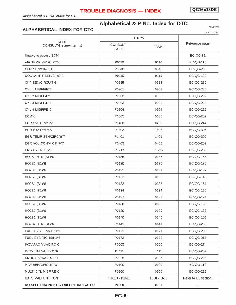
Alphabetical & P No. Index for DTCNCEC0001
ALPHABETICAL INDEX FOR DTCNCEC0001S01
Items(CONSULT-II screen terms)
DTC*5
Reference pageCONSULT-IIGST*2
ECM*1
Unable to access ECM — — EC-QG-81
AIR TEMP SEN/CIRC*6 P0110 0110 EC-QG-116
CMP SEN/CIRCUIT P0340 0340 EC-QG-238
COOLANT T SEN/CIRC*3 P0115 0115 EC-QG-120
CKP SEN/CIRCUIT*6 P0335 0335 EC-QG-232
CYL 1 MISFIRE*6 P0301 0301 EC-QG-222
CYL 2 MISFIRE*6 P0302 0302 EC-QG-222
CYL 3 MISFIRE*6 P0303 0303 EC-QG-222
CYL 4 MISFIRE*6 P0304 0304 EC-QG-222
ECM*6 P0605 0605 EC-QG-282
EGR SYSTEM*6*7 P0400 0400 EC-QG-244
EGR SYSTEM*6*7 P1402 1402 EC-QG-305
EGR TEMP SEN/CIRC*6*7 P1401 1401 EC-QG-300
EGR VOL CON/V CIR*6*7 P0403 0403 EC-QG-252
ENG OVER TEMP P1217 P1217 EC-QG-289
HO2S1 HTR (B1)*6 P0135 0135 EC-QG-166
HO2S1 (B1)*6 P0130 0130 EC-QG-132
HO2S1 (B1)*6 P0131 0131 EC-QG-139
HO2S1 (B1)*6 P0132 0132 EC-QG-145
HO2S1 (B1)*6 P0133 0133 EC-QG-151
HO2S1 (B1)*6 P0134 0134 EC-QG-160
HO2S2 (B1)*6 P0137 0137 EC-QG-171
HO2S2 (B1)*6 P0138 0138 EC-QG-180
HO2S2 (B1)*6 P0139 0139 EC-QG-188
HO2S2 (B1)*6 P0140 0140 EC-QG-197
HO2S2 HTR (B1)*6 P0141 0141 EC-QG-203
FUEL SYS-LEAN/BK1*6 P0171 0171 EC-QG-208
FUEL SYS-RIGH/BK1*6 P0172 0172 EC-QG-215
IACV/AAC VLV/CIRC*6 P0505 0505 EC-QG-274
INT/V TIM V/CIR-B1*6 P1111 1111 EC-QG-284
KNOCK SEN/CIRC-B1 P0325 0325 EC-QG-228
MAF SEN/CIRCUIT*3 P0100 0100 EC-QG-110
MULTI CYL MISFIRE*6 P0300 0300 EC-QG-222
NATS MALFUNCTION P1610 - P1615 1610 - 1615 Refer to EL section.
NO SELF DIAGNOSTIC FAILURE INDICATED P0000 0000 —
TROUBLE DIAGNOSIS — INDEX QG16I18DEAlphabetical & P No. Index for DTC
EC-6
Items(CONSULT-II screen terms)
DTC*5
Reference pageCONSULT-IIGST*2
ECM*1
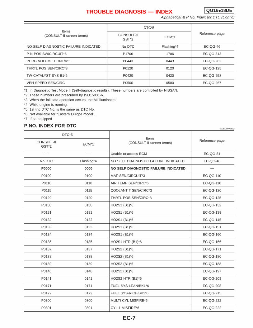
NO SELF DIAGNOSTIC FAILURE INDICATED No DTC Flashing*4 EC-QG-46
P-N POS SW/CIRCUIT*6 P1706 1706 EC-QG-313
PURG VOLUME CONT/V*6 P0443 0443 EC-QG-262
THRTL POS SEN/CIRC*3 P0120 0120 EC-QG-125
TW CATALYST SYS-B1*6 P0420 0420 EC-QG-258
VEH SPEED SEN/CIRC P0500 0500 EC-QG-267
*1: In Diagnostic Test Mode II (Self-diagnostic results). These numbers are controlled by NISSAN.*2: These numbers are prescribed by ISO15031-6.*3: When the fail-safe operation occurs, the MI illuminates.*4: While engine is running.*5: 1st trip DTC No. is the same as DTC No.*6: Not available for “Eastern Europe model”.*7: If so equipped
P NO. INDEX FOR DTCNCEC0001S02
DTC*5Items
(CONSULT-II screen terms)Reference pageCONSULT-II
GST*2ECM*1
— — Unable to access ECM EC-QG-81
No DTC Flashing*4 NO SELF DIAGNOSTIC FAILURE INDICATED EC-QG-46
P0000 0000 NO SELF DIAGNOSTIC FAILURE INDICATED —
P0100 0100 MAF SEN/CIRCUIT*3 EC-QG-110
P0110 0110 AIR TEMP SEN/CIRC*6 EC-QG-116
P0115 0115 COOLANT T SEN/CIRC*3 EC-QG-120
P0120 0120 THRTL POS SEN/CIRC*3 EC-QG-125
P0130 0130 HO2S1 (B1)*6 EC-QG-132
P0131 0131 HO2S1 (B1)*6 EC-QG-139
P0132 0132 HO2S1 (B1)*6 EC-QG-145
P0133 0133 HO2S1 (B1)*6 EC-QG-151
P0134 0134 HO2S1 (B1)*6 EC-QG-160
P0135 0135 HO2S1 HTR (B1)*6 EC-QG-166
P0137 0137 HO2S2 (B1)*6 EC-QG-171
P0138 0138 HO2S2 (B1)*6 EC-QG-180
P0139 0139 HO2S2 (B1)*6 EC-QG-188
P0140 0140 HO2S2 (B1)*6 EC-QG-197
P0141 0141 HO2S2 HTR (B1)*6 EC-QG-203
P0171 0171 FUEL SYS-LEAN/BK1*6 EC-QG-208
P0172 0172 FUEL SYS-RICH/BK1*6 EC-QG-215
P0300 0300 MULTI CYL MISFIRE*6 EC-QG-222
P0301 0301 CYL 1 MISFIRE*6 EC-QG-222
TROUBLE DIAGNOSIS — INDEX QG16I18DEAlphabetical & P No. Index for DTC (Cont’d)
EC-7
DTC*5Items
(CONSULT-II screen terms)Reference pageCONSULT-II
GST*2ECM*1
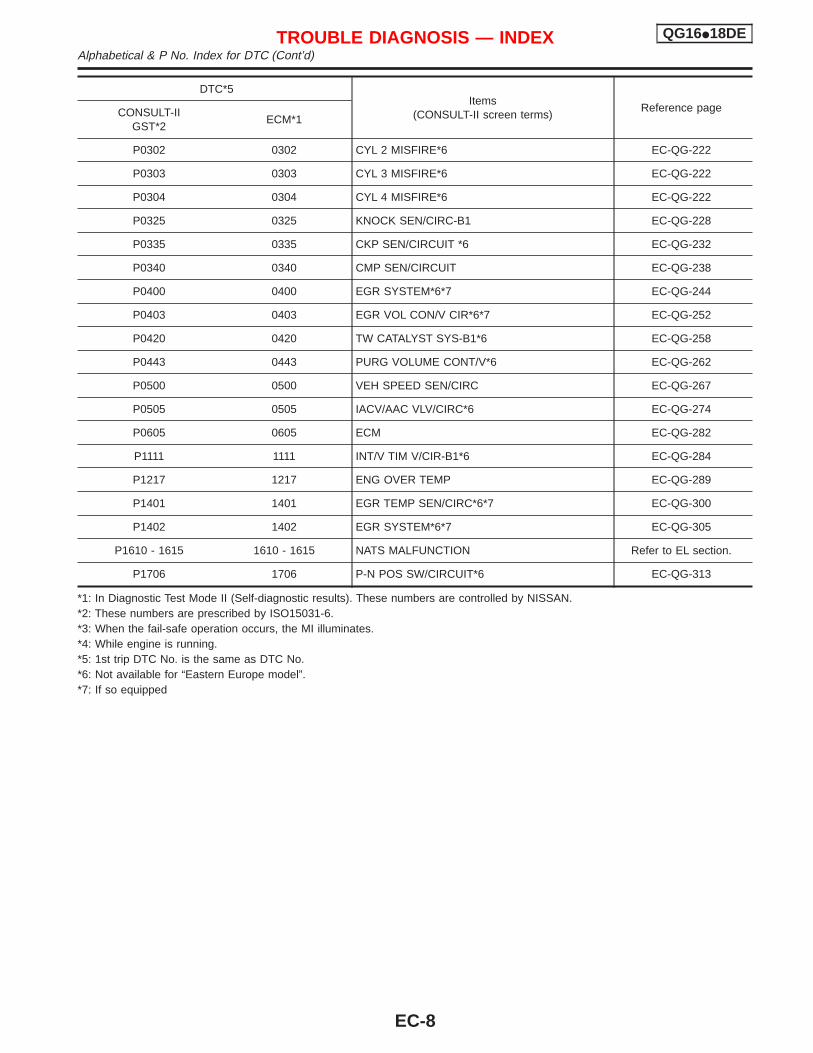
P0302 0302 CYL 2 MISFIRE*6 EC-QG-222
P0303 0303 CYL 3 MISFIRE*6 EC-QG-222
P0304 0304 CYL 4 MISFIRE*6 EC-QG-222
P0325 0325 KNOCK SEN/CIRC-B1 EC-QG-228
P0335 0335 CKP SEN/CIRCUIT *6 EC-QG-232
P0340 0340 CMP SEN/CIRCUIT EC-QG-238
P0400 0400 EGR SYSTEM*6*7 EC-QG-244
P0403 0403 EGR VOL CON/V CIR*6*7 EC-QG-252
P0420 0420 TW CATALYST SYS-B1*6 EC-QG-258
P0443 0443 PURG VOLUME CONT/V*6 EC-QG-262
P0500 0500 VEH SPEED SEN/CIRC EC-QG-267
P0505 0505 IACV/AAC VLV/CIRC*6 EC-QG-274
P0605 0605 ECM EC-QG-282
P1111 1111 INT/V TIM V/CIR-B1*6 EC-QG-284
P1217 1217 ENG OVER TEMP EC-QG-289
P1401 1401 EGR TEMP SEN/CIRC*6*7 EC-QG-300
P1402 1402 EGR SYSTEM*6*7 EC-QG-305
P1610 - 1615 1610 - 1615 NATS MALFUNCTION Refer to EL section.
P1706 1706 P-N POS SW/CIRCUIT*6 EC-QG-313
*1: In Diagnostic Test Mode II (Self-diagnostic results). These numbers are controlled by NISSAN.*2: These numbers are prescribed by ISO15031-6.*3: When the fail-safe operation occurs, the MI illuminates.*4: While engine is running.*5: 1st trip DTC No. is the same as DTC No.*6: Not available for “Eastern Europe model”.*7: If so equipped
TROUBLE DIAGNOSIS — INDEX QG16I18DEAlphabetical & P No. Index for DTC (Cont’d)
EC-8
Supplemental Restraint System (SRS) “AIRBAG” and “SEAT BELT PRE-TENSIONER”
NCEC0002
The Supplemental Restraint System “AIR BAG” and “SEAT BELT PRE-TENSIONER”, used along with a seatbelt, help to reduce the risk or severity of injury to the driver and front passenger in a frontal collision. TheSupplemental Restraint System consists of air bag modules (located in the center of the steering wheel andon the instrument panel on the passenger side), seat belt pre-tensioners, a diagnosis sensor unit, warninglamp, wiring harness and spiral cable.In addition to the supplemental air bag modules for a frontal collision, the supplemental side air bag used alongwith the seat belt helps to reduce the risk or severity of injury to the driver and front passenger in a side col-lision. The supplemental side air bag consists of air bag modules (located in the outer side of front seats),satellite sensor, diagnosis sensor unit (one of components of supplemental air bags for a frontal collision),wiring harness, warning lamp (one of components of supplemental air bags for a frontal collision). Informationnecessary to service the system safely is included in the RS section of this Service Manual.WARNING:I To avoid rendering the SRS inoperative, which could increase the risk of personal injury or death
in the event of a collision which would result in air bag inflation, all maintenance must be performedby an authorized NISSAN dealer.
I Improper maintenance, including incorrect removal and installation of the SRS, can lead to per-sonal injury caused by unintentional activation of the system.
I Do not use electrical test equipment on any circuit related to the SRS unless instructed to in thisService Manual. SRS wiring harnesses (except “SEAT BELT PRE-TENSIONER” connector) can beidentified with yellow harness connector (and with yellow harness protector or yellow insulationtape before the harness connectors).
Precautions for On Board Diagnostic (OBD)System of Engine
NCEC0003
The ECM has an on board diagnostic system. It will light up the malfunction indicator (MI) to warn the driverof a malfunction causing emission deterioration.CAUTION:I Be sure to turn the ignition switch “OFF” and disconnect the negative battery terminal before any
repair or inspection work. The open/short circuit of related switches, sensors, solenoid valves, etc.will cause the MI to light up.
I Be sure to connect and lock the connectors securely after work. A loose (unlocked) connector willcause the MI to light up due to the open circuit. (Be sure the connector is free from water, grease,dirt, bent terminals, etc.)
I Certain systems and components, especially those related to OBD, may use a new style slide-locking type harness connector.For description and how to disconnect, refer to EL section, “Description”, “HARNESS CONNEC-TOR”.
I Be sure to route and secure the harnesses properly after work. The interference of the harness witha bracket, etc. may cause the MI to light up due to the short circuit.
I Be sure to connect rubber tubes properly after work. A misconnected or disconnected rubber tubemay cause the MI to light up due to the malfunction of the EGR system or fuel injection system,etc.
I Be sure to erase the unnecessary malfunction information (repairs completed) from the ECM beforereturning the vehicle to the customer.
PRECAUTIONS QG16I18DESupplemental Restraint System (SRS) “AIR BAG” and “SEAT BELT PRE-TENSIONER”
EC-9
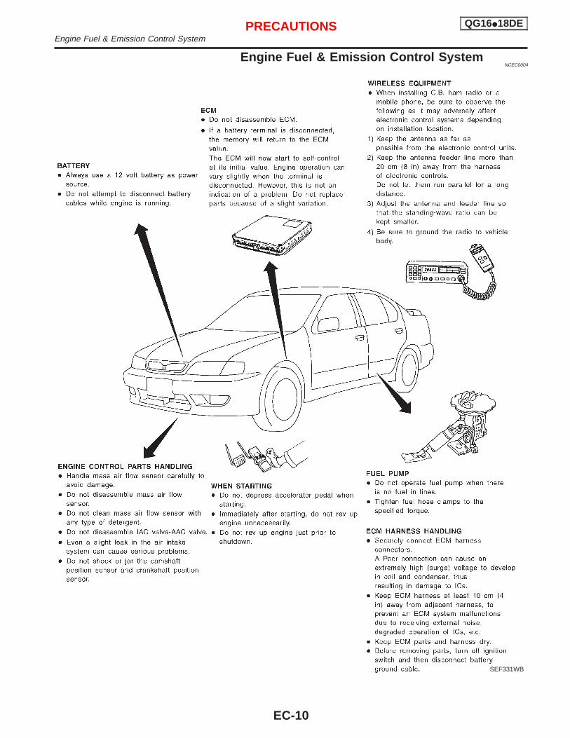
Engine Fuel & Emission Control SystemNCEC0004
SEF331WB
PRECAUTIONS QG16I18DEEngine Fuel & Emission Control System
EC-10
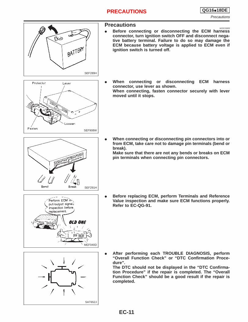
PrecautionsNCEC0005
I Before connecting or disconnecting the ECM harnessconnector, turn ignition switch OFF and disconnect nega-tive battery terminal. Failure to do so may damage theECM because battery voltage is applied to ECM even ifignition switch is turned off.
I When connecting or disconnecting ECM harnessconnector, use lever as shown.When connecting, fasten connector securely with levermoved until it stops.
I When connecting or disconnecting pin connectors into orfrom ECM, take care not to damage pin terminals (bend orbreak).Make sure that there are not any bends or breaks on ECMpin terminals when connecting pin connectors.
I Before replacing ECM, perform Terminals and ReferenceValue inspection and make sure ECM functions properly.Refer to EC-QG-91.
I After performing each TROUBLE DIAGNOSIS, perform“Overall Function Check” or “DTC Confirmation Proce-dure”.The DTC should not be displayed in the “DTC Confirma-tion Procedure” if the repair is completed. The “OverallFunction Check” should be a good result if the repair iscompleted.
SEF289H
SEF908W
SEF291H
MEF040D
SAT652J
PRECAUTIONS QG16I18DEPrecautions
EC-11
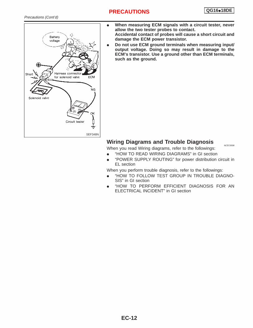
I When measuring ECM signals with a circuit tester, neverallow the two tester probes to contact.Accidental contact of probes will cause a short circuit anddamage the ECM power transistor.
I Do not use ECM ground terminals when measuring input/output voltage. Doing so may result in damage to theECM’s transistor. Use a ground other than ECM terminals,such as the ground.
Wiring Diagrams and Trouble DiagnosisNCEC0006
When you read Wiring diagrams, refer to the followings:I “HOW TO READ WIRING DIAGRAMS” in GI sectionI “POWER SUPPLY ROUTING” for power distribution circuit in
EL sectionWhen you perform trouble diagnosis, refer to the followings:I “HOW TO FOLLOW TEST GROUP IN TROUBLE DIAGNO-
SIS” in GI sectionI “HOW TO PERFORM EFFICIENT DIAGNOSIS FOR AN
ELECTRICAL INCIDENT” in GI section
SEF348N
PRECAUTIONS QG16I18DEPrecautions (Cont’d)
EC-12
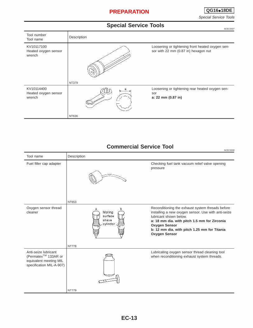
Special Service ToolsNCEC0007
Tool numberTool name
Description
KV10117100Heated oxygen sensorwrench
NT379
Loosening or tightening front heated oxygen sen-sor with 22 mm (0.87 in) hexagon nut
KV10114400Heated oxygen sensorwrench
NT636
Loosening or tightening rear heated oxygen sen-sora: 22 mm (0.87 in)
Commercial Service ToolNCEC0008
Tool name Description
Fuel filler cap adapter
NT653
Checking fuel tank vacuum relief valve openingpressure
Oxygen sensor threadcleaner
NT778
Reconditioning the exhaust system threads beforeinstalling a new oxygen sensor. Use with anti-seizelubricant shown below.a: 18 mm dia. with pitch 1.5 mm for ZirconiaOxygen Sensorb: 12 mm dia. with pitch 1.25 mm for TitaniaOxygen Sensor
Anti-seize lubricant(PermatexTM 133AR orequivalent meeting MILspecification MIL-A-907)
NT779
Lubricating oxygen sensor thread cleaning toolwhen reconditioning exhaust system threads.
PREPARATION QG16I18DESpecial Service Tools
EC-13
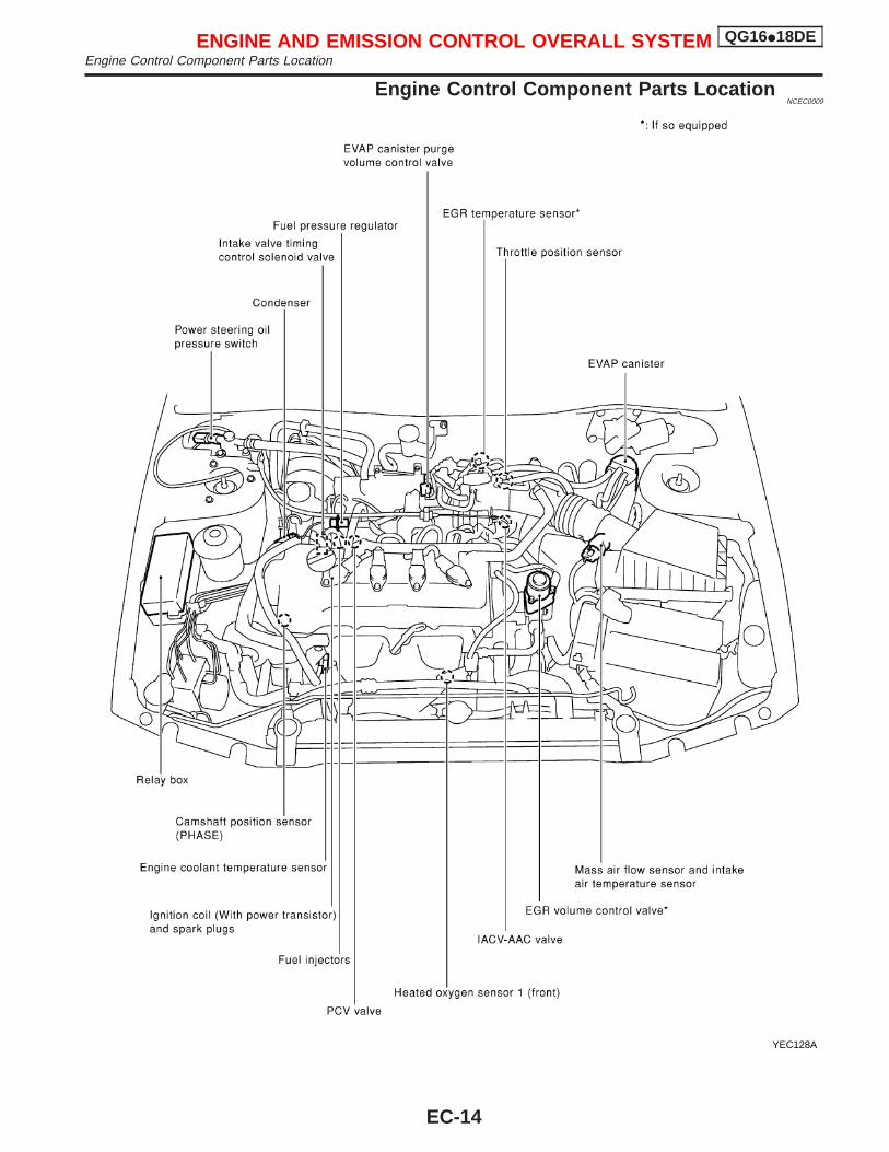
Engine Control Component Parts LocationNCEC0009
YEC128A
ENGINE AND EMISSION CONTROL OVERALL SYSTEM QG16I18DEEngine Control Component Parts Location
EC-14
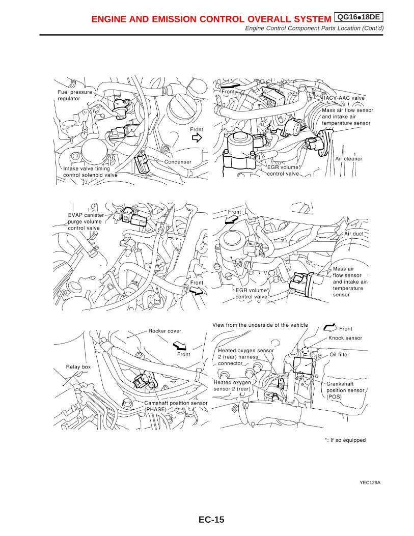
YEC129A
ENGINE AND EMISSION CONTROL OVERALL SYSTEM QG16I18DEEngine Control Component Parts Location (Cont’d)
EC-15
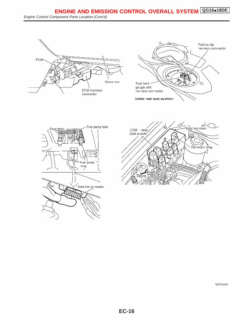
SEF911W
ENGINE AND EMISSION CONTROL OVERALL SYSTEM QG16I18DEEngine Control Component Parts Location (Cont’d)
EC-16
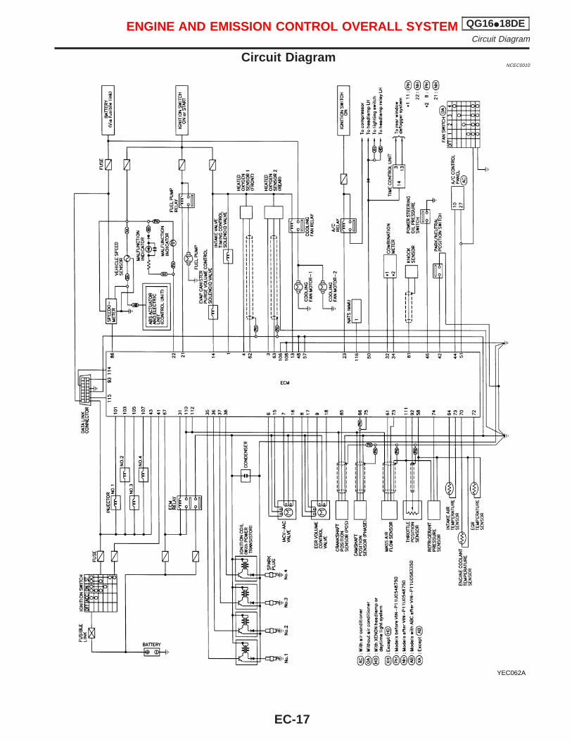
Circuit DiagramNCEC0010
YEC062A
ENGINE AND EMISSION CONTROL OVERALL SYSTEM QG16I18DECircuit Diagram
EC-17
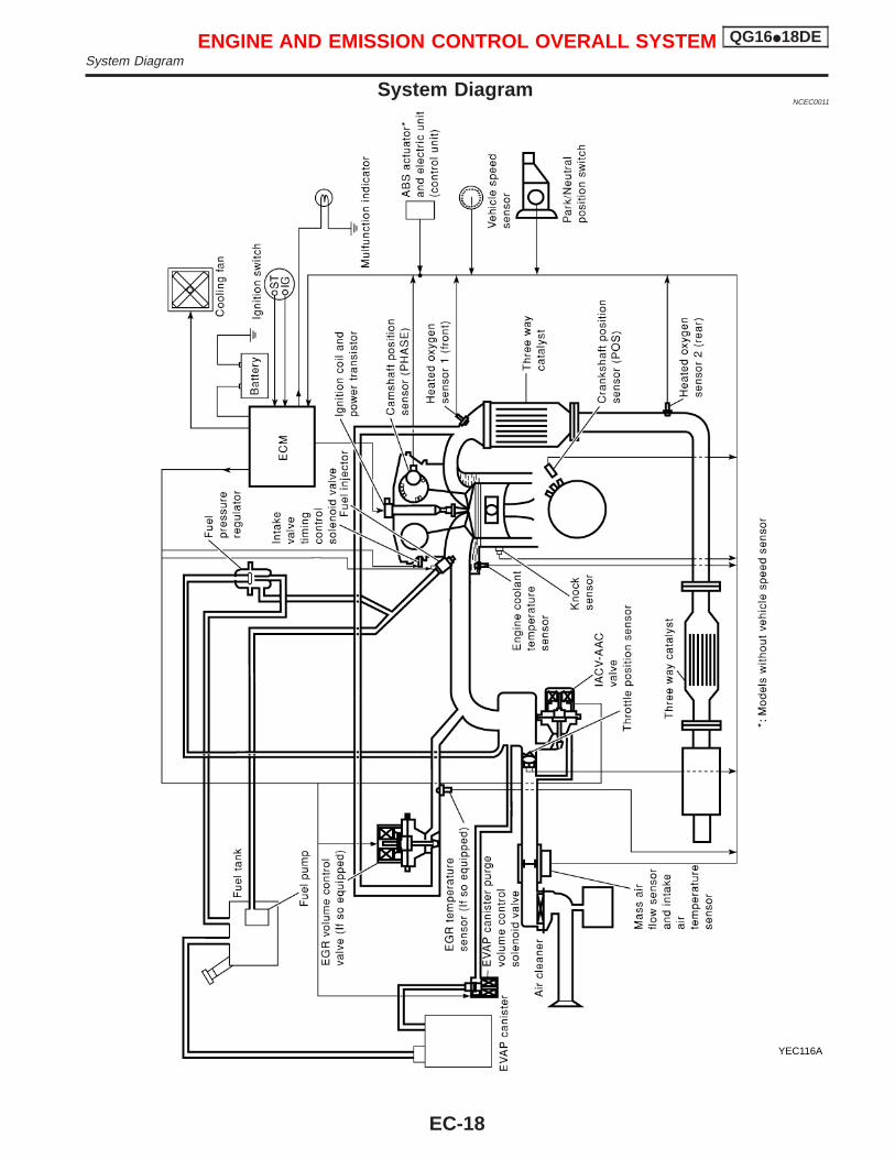
System DiagramNCEC0011
YEC116A
ENGINE AND EMISSION CONTROL OVERALL SYSTEM QG16I18DESystem Diagram
EC-18
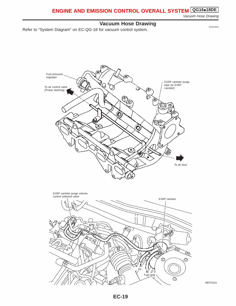
Vacuum Hose DrawingNCEC0012
Refer to “System Diagram” on EC-QG-18 for vacuum control system.
NEF231A
Fuel pressureregulator
EVAP canister purgepipe (to EVAPcanister)
To air duct
To air control valve(Power steering)
EVAP canister purge volumecontrol solenoid valve
EVAP canister
Air
Fuel tank
ENGINE AND EMISSION CONTROL OVERALL SYSTEM QG16I18DEVacuum Hose Drawing
EC-19
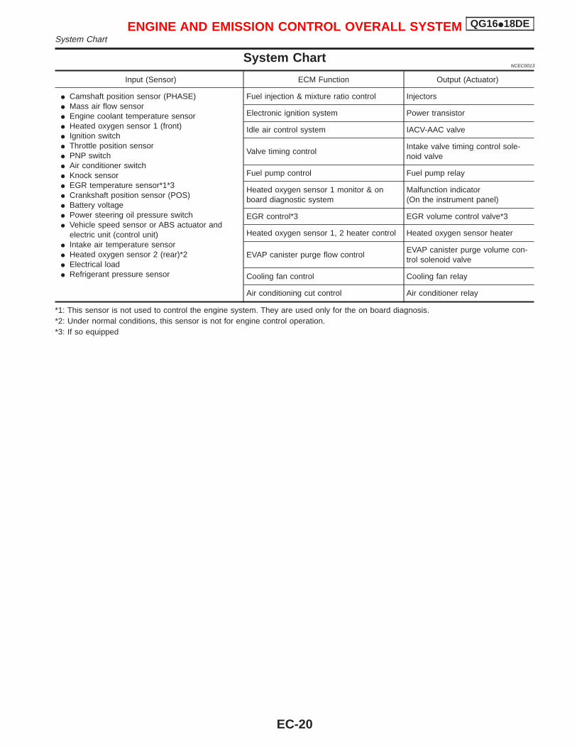
System ChartNCEC0013
Input (Sensor) ECM Function Output (Actuator)
I Camshaft position sensor (PHASE)I Mass air flow sensorI Engine coolant temperature sensorI Heated oxygen sensor 1 (front)I Ignition switchI Throttle position sensorI PNP switchI Air conditioner switchI Knock sensorI EGR temperature sensor*1*3I Crankshaft position sensor (POS)I Battery voltageI Power steering oil pressure switchI Vehicle speed sensor or ABS actuator and
electric unit (control unit)I Intake air temperature sensorI Heated oxygen sensor 2 (rear)*2I Electrical loadI Refrigerant pressure sensor
Fuel injection & mixture ratio control Injectors
Electronic ignition system Power transistor
Idle air control system IACV-AAC valve
Valve timing controlIntake valve timing control sole-noid valve
Fuel pump control Fuel pump relay
Heated oxygen sensor 1 monitor & onboard diagnostic system
Malfunction indicator(On the instrument panel)
EGR control*3 EGR volume control valve*3
Heated oxygen sensor 1, 2 heater control Heated oxygen sensor heater
EVAP canister purge flow controlEVAP canister purge volume con-trol solenoid valve
Cooling fan control Cooling fan relay
Air conditioning cut control Air conditioner relay
*1: This sensor is not used to control the engine system. They are used only for the on board diagnosis.*2: Under normal conditions, this sensor is not for engine control operation.*3: If so equipped
ENGINE AND EMISSION CONTROL OVERALL SYSTEM QG16I18DESystem Chart
EC-20
Multiport Fuel Injection (MFI) SystemDESCRIPTION
NCEC0014
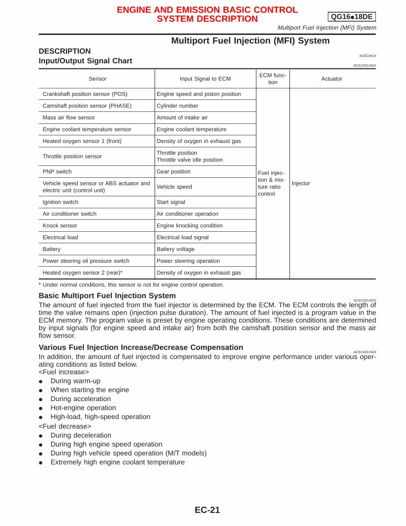
Input/Output Signal ChartNCEC0014S01
Sensor Input Signal to ECMECM func-
tionActuator
Crankshaft position sensor (POS) Engine speed and piston position
Fuel injec-tion & mix-ture ratiocontrol
Injector
Camshaft position sensor (PHASE) Cylinder number
Mass air flow sensor Amount of intake air
Engine coolant temperature sensor Engine coolant temperature
Heated oxygen sensor 1 (front) Density of oxygen in exhaust gas
Throttle position sensorThrottle positionThrottle valve idle position
PNP switch Gear position
Vehicle speed sensor or ABS actuator andelectric unit (control unit)
Vehicle speed
Ignition switch Start signal
Air conditioner switch Air conditioner operation
Knock sensor Engine knocking condition
Electrical load Electrical load signal
Battery Battery voltage
Power steering oil pressure switch Power steering operation
Heated oxygen sensor 2 (rear)* Density of oxygen in exhaust gas
* Under normal conditions, this sensor is not for engine control operation.
Basic Multiport Fuel Injection SystemNCEC0014S02
The amount of fuel injected from the fuel injector is determined by the ECM. The ECM controls the length oftime the valve remains open (injection pulse duration). The amount of fuel injected is a program value in theECM memory. The program value is preset by engine operating conditions. These conditions are determinedby input signals (for engine speed and intake air) from both the camshaft position sensor and the mass airflow sensor.
Various Fuel Injection Increase/Decrease CompensationNCEC0014S03
In addition, the amount of fuel injected is compensated to improve engine performance under various oper-ating conditions as listed below.<Fuel increase>I During warm-upI When starting the engineI During accelerationI Hot-engine operationI High-load, high-speed operation<Fuel decrease>I During decelerationI During high engine speed operationI During high vehicle speed operation (M/T models)I Extremely high engine coolant temperature
ENGINE AND EMISSION BASIC CONTROLSYSTEM DESCRIPTION QG16I18DE
Multiport Fuel Injection (MFI) System
EC-21
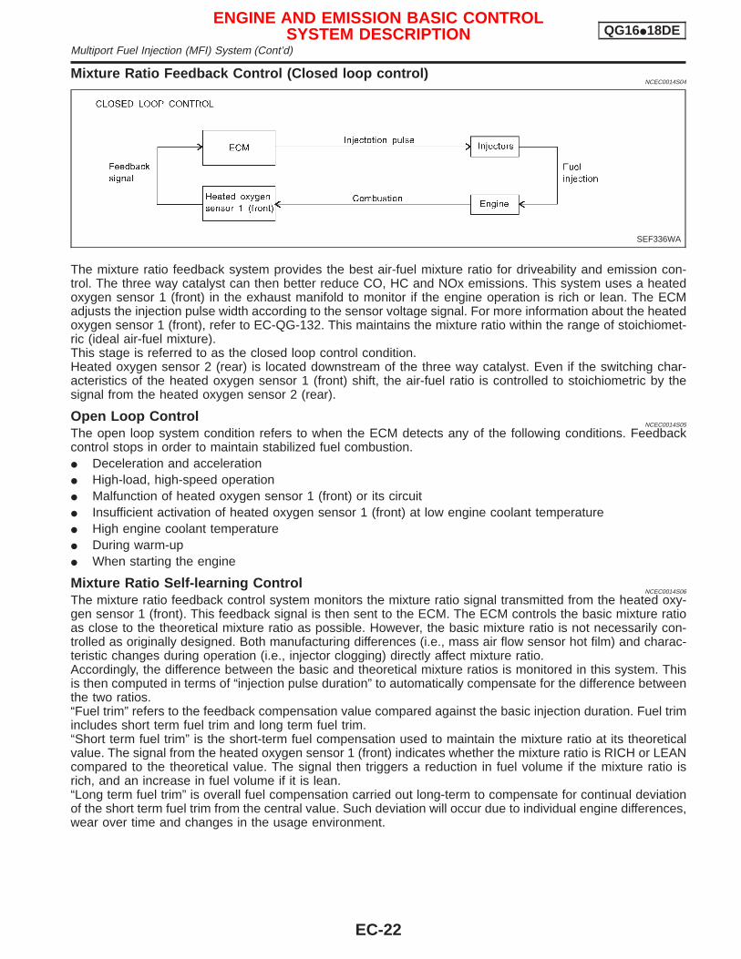
Mixture Ratio Feedback Control (Closed loop control)NCEC0014S04
The mixture ratio feedback system provides the best air-fuel mixture ratio for driveability and emission con-trol. The three way catalyst can then better reduce CO, HC and NOx emissions. This system uses a heatedoxygen sensor 1 (front) in the exhaust manifold to monitor if the engine operation is rich or lean. The ECMadjusts the injection pulse width according to the sensor voltage signal. For more information about the heatedoxygen sensor 1 (front), refer to EC-QG-132. This maintains the mixture ratio within the range of stoichiomet-ric (ideal air-fuel mixture).This stage is referred to as the closed loop control condition.Heated oxygen sensor 2 (rear) is located downstream of the three way catalyst. Even if the switching char-acteristics of the heated oxygen sensor 1 (front) shift, the air-fuel ratio is controlled to stoichiometric by thesignal from the heated oxygen sensor 2 (rear).
Open Loop ControlNCEC0014S05
The open loop system condition refers to when the ECM detects any of the following conditions. Feedbackcontrol stops in order to maintain stabilized fuel combustion.I Deceleration and accelerationI High-load, high-speed operationI Malfunction of heated oxygen sensor 1 (front) or its circuitI Insufficient activation of heated oxygen sensor 1 (front) at low engine coolant temperatureI High engine coolant temperatureI During warm-upI When starting the engine
Mixture Ratio Self-learning ControlNCEC0014S06
The mixture ratio feedback control system monitors the mixture ratio signal transmitted from the heated oxy-gen sensor 1 (front). This feedback signal is then sent to the ECM. The ECM controls the basic mixture ratioas close to the theoretical mixture ratio as possible. However, the basic mixture ratio is not necessarily con-trolled as originally designed. Both manufacturing differences (i.e., mass air flow sensor hot film) and charac-teristic changes during operation (i.e., injector clogging) directly affect mixture ratio.Accordingly, the difference between the basic and theoretical mixture ratios is monitored in this system. Thisis then computed in terms of “injection pulse duration” to automatically compensate for the difference betweenthe two ratios.“Fuel trim” refers to the feedback compensation value compared against the basic injection duration. Fuel trimincludes short term fuel trim and long term fuel trim.“Short term fuel trim” is the short-term fuel compensation used to maintain the mixture ratio at its theoreticalvalue. The signal from the heated oxygen sensor 1 (front) indicates whether the mixture ratio is RICH or LEANcompared to the theoretical value. The signal then triggers a reduction in fuel volume if the mixture ratio isrich, and an increase in fuel volume if it is lean.“Long term fuel trim” is overall fuel compensation carried out long-term to compensate for continual deviationof the short term fuel trim from the central value. Such deviation will occur due to individual engine differences,wear over time and changes in the usage environment.
SEF336WA
ENGINE AND EMISSION BASIC CONTROLSYSTEM DESCRIPTION QG16I18DE
Multiport Fuel Injection (MFI) System (Cont’d)
EC-22
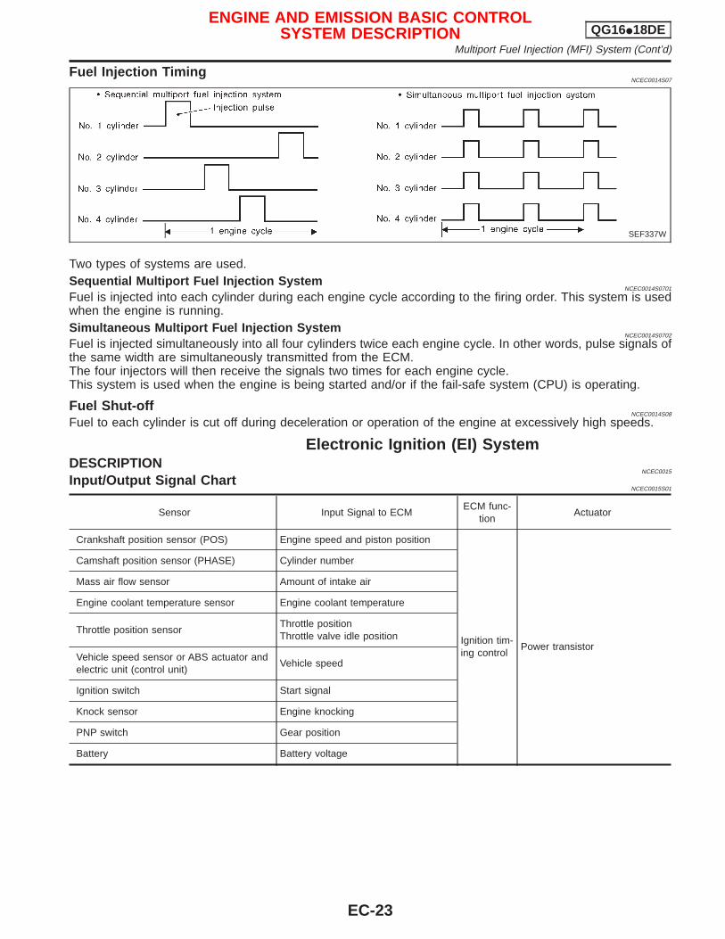
Fuel Injection TimingNCEC0014S07
Two types of systems are used.Sequential Multiport Fuel Injection System
NCEC0014S0701
Fuel is injected into each cylinder during each engine cycle according to the firing order. This system is usedwhen the engine is running.Simultaneous Multiport Fuel Injection System
NCEC0014S0702
Fuel is injected simultaneously into all four cylinders twice each engine cycle. In other words, pulse signals ofthe same width are simultaneously transmitted from the ECM.The four injectors will then receive the signals two times for each engine cycle.This system is used when the engine is being started and/or if the fail-safe system (CPU) is operating.
Fuel Shut-offNCEC0014S08
Fuel to each cylinder is cut off during deceleration or operation of the engine at excessively high speeds.
Electronic Ignition (EI) SystemDESCRIPTION
NCEC0015
Input/Output Signal ChartNCEC0015S01
Sensor Input Signal to ECMECM func-
tionActuator
Crankshaft position sensor (POS) Engine speed and piston position
Ignition tim-ing control
Power transistor
Camshaft position sensor (PHASE) Cylinder number
Mass air flow sensor Amount of intake air
Engine coolant temperature sensor Engine coolant temperature
Throttle position sensorThrottle positionThrottle valve idle position
Vehicle speed sensor or ABS actuator andelectric unit (control unit)
Vehicle speed
Ignition switch Start signal
Knock sensor Engine knocking
PNP switch Gear position
Battery Battery voltage
SEF337W
ENGINE AND EMISSION BASIC CONTROLSYSTEM DESCRIPTION QG16I18DE
Multiport Fuel Injection (MFI) System (Cont’d)
EC-23
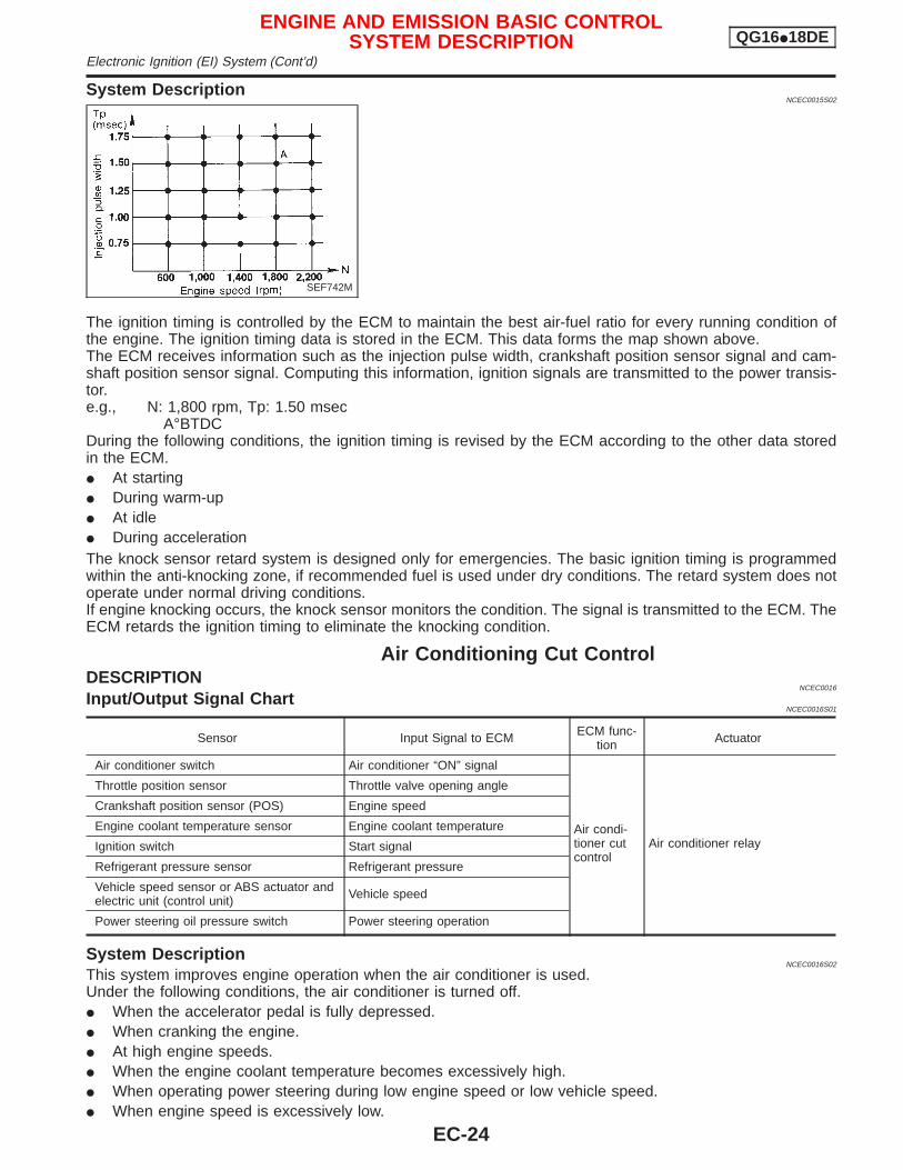
System DescriptionNCEC0015S02
The ignition timing is controlled by the ECM to maintain the best air-fuel ratio for every running condition ofthe engine. The ignition timing data is stored in the ECM. This data forms the map shown above.The ECM receives information such as the injection pulse width, crankshaft position sensor signal and cam-shaft position sensor signal. Computing this information, ignition signals are transmitted to the power transis-tor.e.g., N: 1,800 rpm, Tp: 1.50 msec
A°BTDCDuring the following conditions, the ignition timing is revised by the ECM according to the other data storedin the ECM.I At startingI During warm-upI At idleI During accelerationThe knock sensor retard system is designed only for emergencies. The basic ignition timing is programmedwithin the anti-knocking zone, if recommended fuel is used under dry conditions. The retard system does notoperate under normal driving conditions.If engine knocking occurs, the knock sensor monitors the condition. The signal is transmitted to the ECM. TheECM retards the ignition timing to eliminate the knocking condition.
Air Conditioning Cut ControlDESCRIPTION
NCEC0016
Input/Output Signal ChartNCEC0016S01
Sensor Input Signal to ECM ECM func-tion Actuator
Air conditioner switch Air conditioner “ON” signal
Air condi-tioner cutcontrol
Air conditioner relay
Throttle position sensor Throttle valve opening angle
Crankshaft position sensor (POS) Engine speed
Engine coolant temperature sensor Engine coolant temperature
Ignition switch Start signal
Refrigerant pressure sensor Refrigerant pressure
Vehicle speed sensor or ABS actuator andelectric unit (control unit) Vehicle speed
Power steering oil pressure switch Power steering operation
System DescriptionNCEC0016S02
This system improves engine operation when the air conditioner is used.Under the following conditions, the air conditioner is turned off.I When the accelerator pedal is fully depressed.I When cranking the engine.I At high engine speeds.I When the engine coolant temperature becomes excessively high.I When operating power steering during low engine speed or low vehicle speed.I When engine speed is excessively low.
SEF742M
ENGINE AND EMISSION BASIC CONTROLSYSTEM DESCRIPTION QG16I18DE
Electronic Ignition (EI) System (Cont’d)
EC-24
Fuel Cut Control (at no load & high enginespeed)
DESCRIPTIONNCEC0017
Input/Output Signal ChartNCEC0017S01
Sensor Input Signal to ECMECM func-
tionActuator
Vehicle speed sensor or ABS actuator andelectric unit (control unit)
Vehicle speed
Fuel cutcontrol
Injectors
PNP switch Neutral position
Throttle position sensor Throttle position
Engine coolant temperature sensor Engine coolant temperature
Crankshaft position sensor (POS) Engine speed
If the engine speed is above 3,950 rpm with no load, (for example, in Neutral and engine speed over 4,000rpm) fuel will be cut off after some time. The exact time when the fuel is cut off varies based on engine speed.Fuel cut will operate until the engine speed reaches 1,150 rpm, then fuel cut is cancelled.NOTE:This function is different from deceleration control listed under “Multiport Fuel Injection (MFI) System”,EC-QG-21.
Evaporative Emission SystemDESCRIPTION
NCEC0018
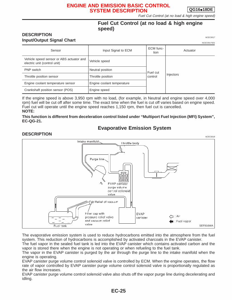
The evaporative emission system is used to reduce hydrocarbons emitted into the atmosphere from the fuelsystem. This reduction of hydrocarbons is accomplished by activated charcoals in the EVAP canister.The fuel vapor in the sealed fuel tank is led into the EVAP canister which contains activated carbon and thevapor is stored there when the engine is not operating or when refueling to the fuel tank.The vapor in the EVAP canister is purged by the air through the purge line to the intake manifold when theengine is operating.EVAP canister purge volume control solenoid valve is controlled by ECM. When the engine operates, the flowrate of vapor controlled by EVAP canister purge volume control solenoid valve is proportionally regulated asthe air flow increases.EVAP canister purge volume control solenoid valve also shuts off the vapor purge line during decelerating andidling.
SEF916WA
ENGINE AND EMISSION BASIC CONTROLSYSTEM DESCRIPTION QG16I18DE
Fuel Cut Control (at no load & high engine speed)
EC-25
INSPECTIONNCEC0019
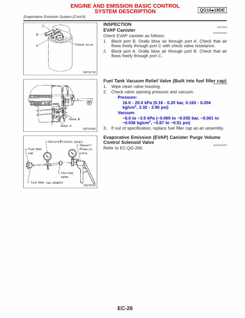
EVAP CanisterNCEC0019S01
Check EVAP canister as follows:1. Block port B. Orally blow air through port A. Check that air
flows freely through port C with check valve resistance.2. Block port A. Orally blow air through port B. Check that air
flows freely through port C.
Fuel Tank Vacuum Relief Valve (Built into fuel filler cap)NCEC0019S03
1. Wipe clean valve housing.2. Check valve opening pressure and vacuum.
Pressure:16.0 - 20.0 kPa (0.16 - 0.20 bar, 0.163 - 0.204kg/cm 2, 2.32 - 2.90 psi)
Vacuum:−6.0 to −3.5 kPa (−0.060 to −0.035 bar, −0.061 to−0.036 kg/cm 2, −0.87 to −0.51 psi)
3. If out of specification, replace fuel filler cap as an assembly.
Evaporative Emission (EVAP) Canister Purge VolumeControl Solenoid Valve
NCEC0019S07
Refer to EC-QG-266.
SEF917W
SEF918W
SEF943S
ENGINE AND EMISSION BASIC CONTROLSYSTEM DESCRIPTION QG16I18DE
Evaporative Emission System (Cont’d)
EC-26
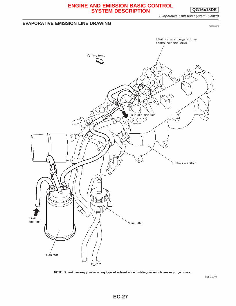
EVAPORATIVE EMISSION LINE DRAWINGNCEC0020
SEF919W
ENGINE AND EMISSION BASIC CONTROLSYSTEM DESCRIPTION QG16I18DE
Evaporative Emission System (Cont’d)
EC-27
Positive Crankcase VentilationDESCRIPTION
NCEC0022
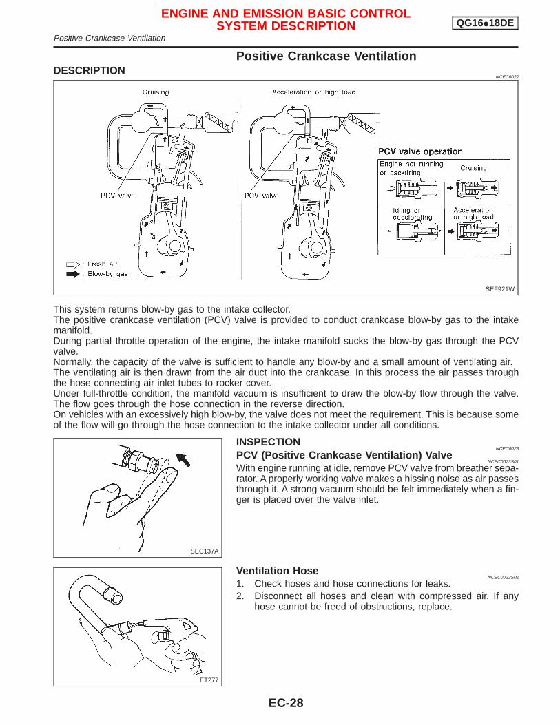
This system returns blow-by gas to the intake collector.The positive crankcase ventilation (PCV) valve is provided to conduct crankcase blow-by gas to the intakemanifold.During partial throttle operation of the engine, the intake manifold sucks the blow-by gas through the PCVvalve.Normally, the capacity of the valve is sufficient to handle any blow-by and a small amount of ventilating air.The ventilating air is then drawn from the air duct into the crankcase. In this process the air passes throughthe hose connecting air inlet tubes to rocker cover.Under full-throttle condition, the manifold vacuum is insufficient to draw the blow-by flow through the valve.The flow goes through the hose connection in the reverse direction.On vehicles with an excessively high blow-by, the valve does not meet the requirement. This is because someof the flow will go through the hose connection to the intake collector under all conditions.
INSPECTIONNCEC0023
PCV (Positive Crankcase Ventilation) ValveNCEC0023S01
With engine running at idle, remove PCV valve from breather sepa-rator. A properly working valve makes a hissing noise as air passesthrough it. A strong vacuum should be felt immediately when a fin-ger is placed over the valve inlet.
Ventilation HoseNCEC0023S02
1. Check hoses and hose connections for leaks.2. Disconnect all hoses and clean with compressed air. If any
hose cannot be freed of obstructions, replace.
SEF921W
SEC137A
ET277
ENGINE AND EMISSION BASIC CONTROLSYSTEM DESCRIPTION QG16I18DE
Positive Crankcase Ventilation
EC-28
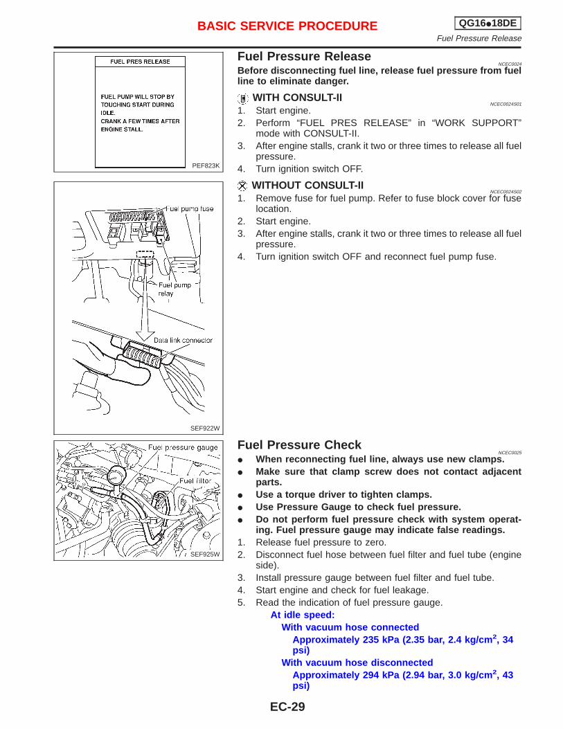
Fuel Pressure ReleaseNCEC0024
Before disconnecting fuel line, release fuel pressure from fuelline to eliminate danger.
WITH CONSULT-IINCEC0024S01
1. Start engine.2. Perform “FUEL PRES RELEASE” in “WORK SUPPORT”
mode with CONSULT-II.3. After engine stalls, crank it two or three times to release all fuel
pressure.4. Turn ignition switch OFF.
WITHOUT CONSULT-IINCEC0024S02
1. Remove fuse for fuel pump. Refer to fuse block cover for fuselocation.
2. Start engine.3. After engine stalls, crank it two or three times to release all fuel
pressure.4. Turn ignition switch OFF and reconnect fuel pump fuse.
Fuel Pressure CheckNCEC0025
I When reconnecting fuel line, always use new clamps.I Make sure that clamp screw does not contact adjacent
parts.I Use a torque driver to tighten clamps.I Use Pressure Gauge to check fuel pressure.I Do not perform fuel pressure check with system operat-
ing. Fuel pressure gauge may indicate false readings.1. Release fuel pressure to zero.2. Disconnect fuel hose between fuel filter and fuel tube (engine
side).3. Install pressure gauge between fuel filter and fuel tube.4. Start engine and check for fuel leakage.5. Read the indication of fuel pressure gauge.
At idle speed:With vacuum hose connected
Approximately 235 kPa (2.35 bar, 2.4 kg/cm 2, 34psi)
With vacuum hose disconnectedApproximately 294 kPa (2.94 bar, 3.0 kg/cm 2, 43psi)
PEF823K
SEF922W
SEF925W
BASIC SERVICE PROCEDURE QG16I18DEFuel Pressure Release
EC-29
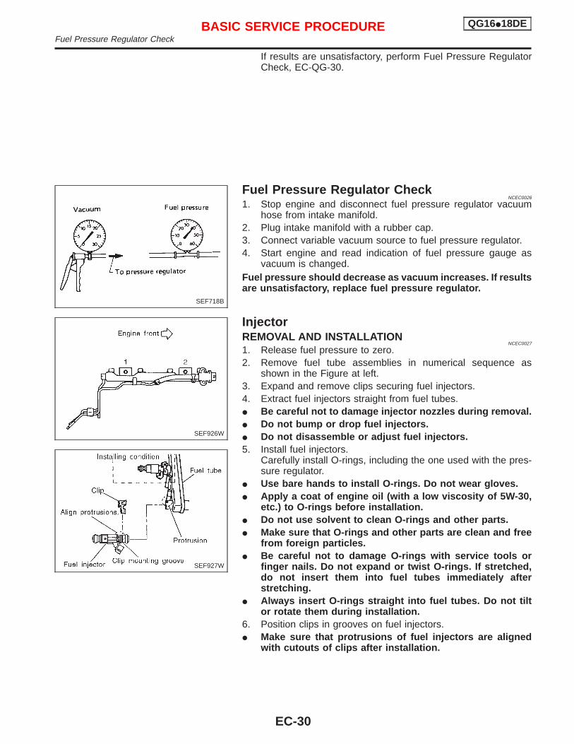
If results are unsatisfactory, perform Fuel Pressure RegulatorCheck, EC-QG-30.
Fuel Pressure Regulator CheckNCEC0026
1. Stop engine and disconnect fuel pressure regulator vacuumhose from intake manifold.
2. Plug intake manifold with a rubber cap.3. Connect variable vacuum source to fuel pressure regulator.4. Start engine and read indication of fuel pressure gauge as
vacuum is changed.Fuel pressure should decrease as vacuum increases. If resultsare unsatisfactory, replace fuel pressure regulator.
InjectorREMOVAL AND INSTALLATION
NCEC0027
1. Release fuel pressure to zero.2. Remove fuel tube assemblies in numerical sequence as
shown in the Figure at left.3. Expand and remove clips securing fuel injectors.4. Extract fuel injectors straight from fuel tubes.I Be careful not to damage injector nozzles during removal.I Do not bump or drop fuel injectors.I Do not disassemble or adjust fuel injectors.5. Install fuel injectors.
Carefully install O-rings, including the one used with the pres-sure regulator.
I Use bare hands to install O-rings. Do not wear gloves.I Apply a coat of engine oil (with a low viscosity of 5W-30,
etc.) to O-rings before installation.I Do not use solvent to clean O-rings and other parts.I Make sure that O-rings and other parts are clean and free
from foreign particles.I Be careful not to damage O-rings with service tools or
finger nails. Do not expand or twist O-rings. If stretched,do not insert them into fuel tubes immediately afterstretching.
I Always insert O-rings straight into fuel tubes. Do not tiltor rotate them during installation.
6. Position clips in grooves on fuel injectors.I Make sure that protrusions of fuel injectors are aligned
with cutouts of clips after installation.
SEF718B
SEF926W
SEF927W
BASIC SERVICE PROCEDURE QG16I18DEFuel Pressure Regulator Check
EC-30
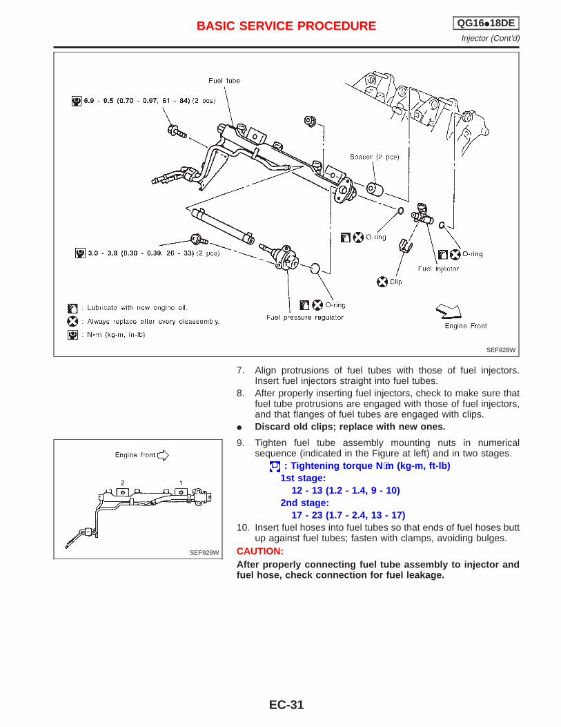
7. Align protrusions of fuel tubes with those of fuel injectors.Insert fuel injectors straight into fuel tubes.
8. After properly inserting fuel injectors, check to make sure thatfuel tube protrusions are engaged with those of fuel injectors,and that flanges of fuel tubes are engaged with clips.
I Discard old clips; replace with new ones.
9. Tighten fuel tube assembly mounting nuts in numericalsequence (indicated in the Figure at left) and in two stages.
: Tightening torque N ⋅m (kg-m, ft-lb)1st stage:
12 - 13 (1.2 - 1.4, 9 - 10)2nd stage:
17 - 23 (1.7 - 2.4, 13 - 17)10. Insert fuel hoses into fuel tubes so that ends of fuel hoses butt
up against fuel tubes; fasten with clamps, avoiding bulges.CAUTION:After properly connecting fuel tube assembly to injector andfuel hose, check connection for fuel leakage.
SEF928W
SEF929W
BASIC SERVICE PROCEDURE QG16I18DEInjector (Cont’d)
EC-31
Idle Speed/Ignition Timing/Idle Mixture RatioAdjustment
NCEC0028
DIRECT IGNITION SYSTEM — HOW TO CHECK IDLESPEED AND IGNITION TIMING
NCEC0028S03
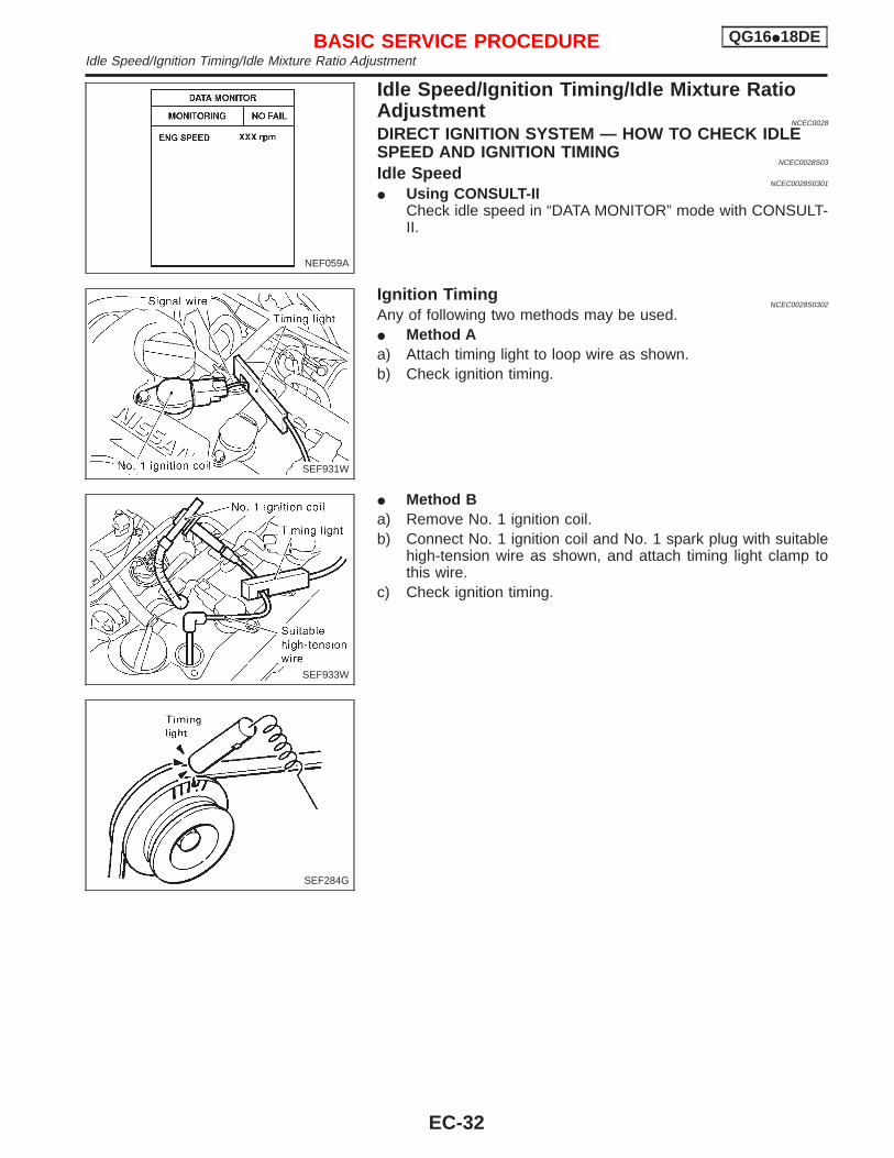
Idle SpeedNCEC0028S0301
I Using CONSULT-IICheck idle speed in “DATA MONITOR” mode with CONSULT-II.
Ignition TimingNCEC0028S0302
Any of following two methods may be used.I Method Aa) Attach timing light to loop wire as shown.b) Check ignition timing.
I Method Ba) Remove No. 1 ignition coil.b) Connect No. 1 ignition coil and No. 1 spark plug with suitable
high-tension wire as shown, and attach timing light clamp tothis wire.
c) Check ignition timing.
NEF059A
SEF931W
SEF933W
SEF284G
BASIC SERVICE PROCEDURE QG16I18DEIdle Speed/Ignition Timing/Idle Mixture Ratio Adjustment
EC-32
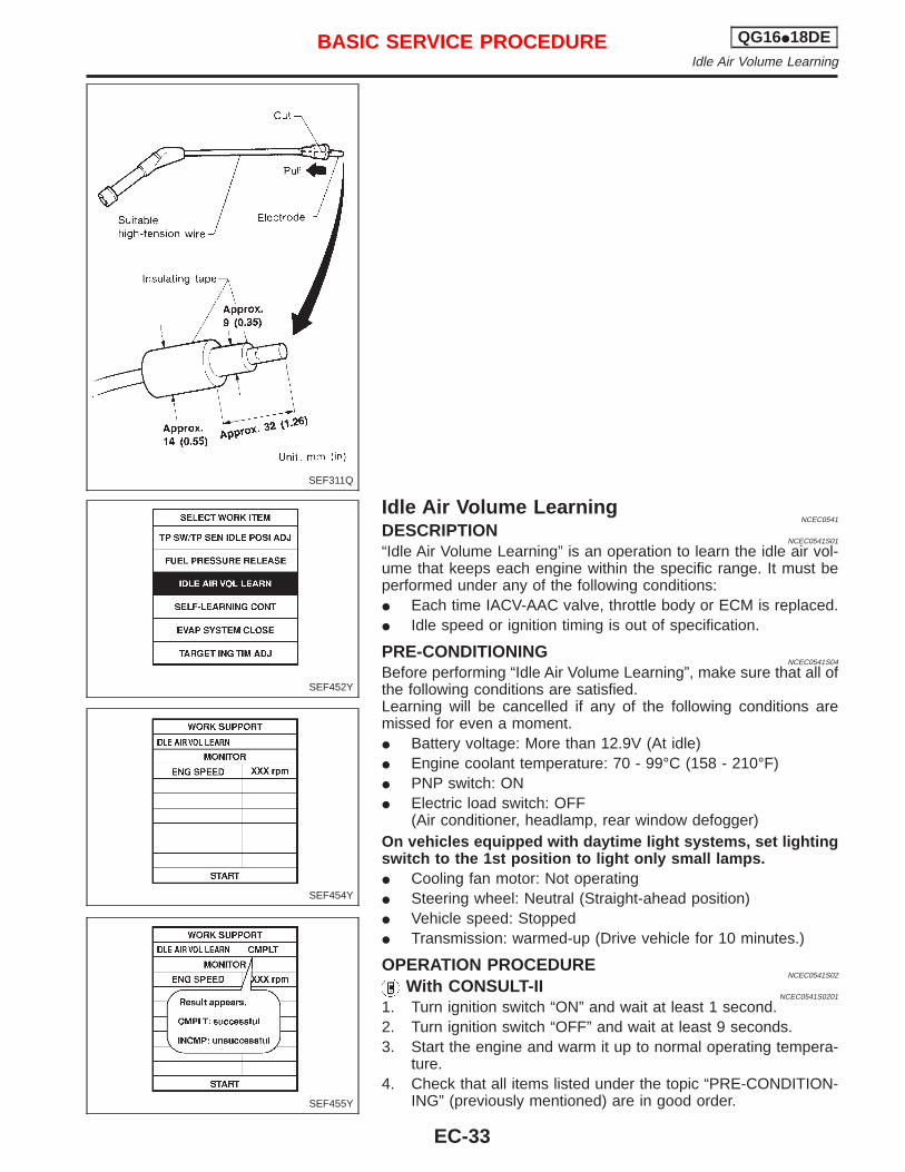
Idle Air Volume LearningNCEC0541
DESCRIPTIONNCEC0541S01
“Idle Air Volume Learning” is an operation to learn the idle air vol-ume that keeps each engine within the specific range. It must beperformed under any of the following conditions:I Each time IACV-AAC valve, throttle body or ECM is replaced.I Idle speed or ignition timing is out of specification.
PRE-CONDITIONINGNCEC0541S04
Before performing “Idle Air Volume Learning”, make sure that all ofthe following conditions are satisfied.Learning will be cancelled if any of the following conditions aremissed for even a moment.I Battery voltage: More than 12.9V (At idle)I Engine coolant temperature: 70 - 99°C (158 - 210°F)I PNP switch: ONI Electric load switch: OFF
(Air conditioner, headlamp, rear window defogger)On vehicles equipped with daytime light systems, set lightingswitch to the 1st position to light only small lamps.I Cooling fan motor: Not operatingI Steering wheel: Neutral (Straight-ahead position)I Vehicle speed: StoppedI Transmission: warmed-up (Drive vehicle for 10 minutes.)
OPERATION PROCEDURENCEC0541S02
With CONSULT-IINCEC0541S0201
1. Turn ignition switch “ON” and wait at least 1 second.2. Turn ignition switch “OFF” and wait at least 9 seconds.3. Start the engine and warm it up to normal operating tempera-
ture.4. Check that all items listed under the topic “PRE-CONDITION-
ING” (previously mentioned) are in good order.
SEF311Q
SEF452Y
SEF454Y
SEF455Y
BASIC SERVICE PROCEDURE QG16I18DEIdle Air Volume Learning
EC-33
5. Turn ignition switch “OFF” and wait at least 9 seconds.6. Start the engine and let it to idle for at least 28 seconds.7. Select “IDLE AIR VOL LEARN” in “WORK SUPPORT” mode.8. Touch “START” and wait 20 seconds.9. Make sure that “CMPLT” is displayed on CONSULT-II screen.
If “INCMP” is displayed, “Idle Air Volume Learning” will not becarried out successfully. In this case, find the cause of theproblem by referring to the NOTE below.
10. Rev up the engine two or three times. Make sure that idlespeed and ignition timing are close to or within specifications.
ITEM SPECIFICATION
Idle speed 700 ± 50 rpm
Ignition timing 8° ± 5° BTDC
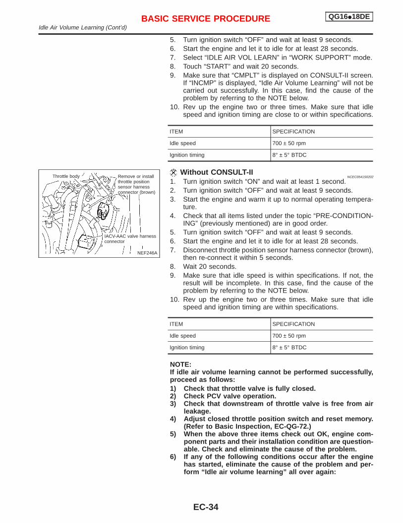
Without CONSULT-IINCEC0541S0202
1. Turn ignition switch “ON” and wait at least 1 second.2. Turn ignition switch “OFF” and wait at least 9 seconds.3. Start the engine and warm it up to normal operating tempera-
ture.4. Check that all items listed under the topic “PRE-CONDITION-
ING” (previously mentioned) are in good order.5. Turn ignition switch “OFF” and wait at least 9 seconds.6. Start the engine and let it to idle for at least 28 seconds.7. Disconnect throttle position sensor harness connector (brown),
then re-connect it within 5 seconds.8. Wait 20 seconds.9. Make sure that idle speed is within specifications. If not, the
result will be incomplete. In this case, find the cause of theproblem by referring to the NOTE below.
10. Rev up the engine two or three times. Make sure that idlespeed and ignition timing are within specifications.
ITEM SPECIFICATION
Idle speed 700 ± 50 rpm
Ignition timing 8° ± 5° BTDC
NOTE:If idle air volume learning cannot be performed successfully,proceed as follows:1) Check that throttle valve is fully closed.2) Check PCV valve operation.3) Check that downstream of throttle valve is free from air
leakage.4) Adjust closed throttle position switch and reset memory.
(Refer to Basic Inspection, EC-QG-72.)5) When the above three items check out OK, engine com-
ponent parts and their installation condition are question-able. Check and eliminate the cause of the problem.
6) If any of the following conditions occur after the enginehas started, eliminate the cause of the problem and per-form “Idle air volume learning” all over again:
NEF246A
Throttle body.Remove or installthrottle positionsensor harnessconnector (brown)
IACV-AAC valve harnessconnector
BASIC SERVICE PROCEDURE QG16I18DEIdle Air Volume Learning (Cont’d)
EC-34

I Engine stalls.I Erroneous idle.I Blown fuses related to IACV-AAC valve system.
BASIC SERVICE PROCEDURE QG16I18DEIdle Air Volume Learning (Cont’d)
EC-35
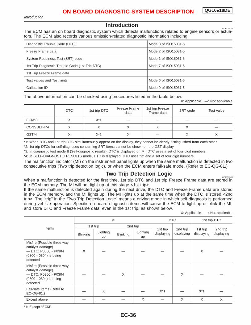
IntroductionNCEC0029
The ECM has an on board diagnostic system which detects malfunctions related to engine sensors or actua-tors. The ECM also records various emission-related diagnostic information including:
Diagnostic Trouble Code (DTC) Mode 3 of ISO15031-5
Freeze Frame data Mode 2 of ISO15031-5
System Readiness Test (SRT) code Mode 1 of ISO15031-5
1st Trip Diagnostic Trouble Code (1st Trip DTC) Mode 7 of ISO15031-5
1st Trip Freeze Frame data
Test values and Test limits Mode 6 of ISO15031-5
Calibration ID Mode 9 of ISO15031-5
The above information can be checked using procedures listed in the table below.X: Applicable —: Not applicable
DTC 1st trip DTCFreeze Frame
data1st trip Freeze
Frame dataSRT code Test value
ECM*3 X X*1 — — — —
CONSULT-II*4 X X X X X —
GST*4 X X*2 X — X X
*1: When DTC and 1st trip DTC simultaneously appear on the display, they cannot be clearly distinguished from each other.*2: 1st trip DTCs for self-diagnoses concerning SRT items cannot be shown on the GST display.*3: In diagnostic test mode II (Self-diagnostic results), DTC is displayed on MI. DTC uses a set of four digit numbers.*4: In SELF-DIAGNOSTIC RESULTS mode, DTC is displayed. DTC uses “P” and a set of four digit numbers.
The malfunction indicator (MI) on the instrument panel lights up when the same malfunction is detected in twoconsecutive trips (Two trip detection logic), or when the ECM enters fail-safe mode. (Refer to EC-QG-81.)
Two Trip Detection LogicNCEC0030
When a malfunction is detected for the first time, 1st trip DTC and 1st trip Freeze Frame data are stored inthe ECM memory. The MI will not light up at this stage <1st trip>.If the same malfunction is detected again during the next drive, the DTC and Freeze Frame data are storedin the ECM memory, and the MI lights up. The MI lights up at the same time when the DTC is stored <2ndtrip>. The “trip” in the “Two Trip Detection Logic” means a driving mode in which self-diagnosis is performedduring vehicle operation. Specific on board diagnostic items will cause the ECM to light up or blink the MI,and store DTC and Freeze Frame data, even in the 1st trip, as shown below.
X: Applicable —: Not applicable
Items
MI DTC 1st trip DTC
1st trip 2nd trip1st trip
displaying2nd trip
displaying1st trip
displaying2nd trip
displayingBlinkingLighting
upBlinking
Lightingup
Misfire (Possible three waycatalyst damage)— DTC: P0300 - P0304(0300 - 0304) is beingdetected
X — — — — — X —
Misfire (Possible three waycatalyst damage)— DTC: P0300 - P0304(0300 - 0304) is beingdetected
— — X — — X — —
Fail-safe items (Refer toEC-QG-81.)
— X — — X*1 — X*1 —
Except above — — — X — X X X
*1: Except “ECM”.
ON BOARD DIAGNOSTIC SYSTEM DESCRIPTION QG16I18DEIntroduction
EC-36
Emission-related Diagnostic InformationNCEC0031
DTC AND 1ST TRIP DTCNCEC0031S01
The 1st trip DTC (whose number is the same as the DTC number) is displayed for the latest self-diagnosticresult obtained. If the ECM memory was cleared previously, and the 1st trip DTC did not reoccur, the 1st tripDTC will not be displayed. If a malfunction is detected during the 1st trip, the 1st trip DTC is stored in the ECMmemory. The MI will not light up (two trip detection logic). If the same malfunction is not detected in the 2ndtrip (meeting the required driving pattern), the 1st trip DTC is cleared from the ECM memory. If the same mal-function is detected in the 2nd trip, both the 1st trip DTC and DTC are stored in the ECM memory and the MIlights up. In other words, the DTC is stored in the ECM memory and the MI lights up when the same malfunc-tion occurs in two consecutive trips. If a 1st trip DTC is stored and a non-diagnostic operation is performedbetween the 1st and 2nd trips, only the 1st trip DTC will continue to be stored. For malfunctions that blink orlight up the MI during the 1st trip, the DTC and 1st trip DTC are stored in the ECM memory.Procedures for clearing the DTC and the 1st trip DTC from the ECM memory are described in “HOW TOERASE EMISSION-RELATED DIAGNOSTIC INFORMATION”. Refer to EC-QG-44.For malfunctions in which 1st trip DTCs are displayed, refer to EC-QG-42. These items are required by legalregulations to continuously monitor the system/component. In addition, the items monitored non-continuouslyare also displayed on CONSULT-II.1st trip DTC is specified in Mode 7 of ISO15031-5. 1st trip DTC detection occurs without lighting up the MIand therefore does not warn the driver of a problem. However, 1st trip DTC detection will not prevent thevehicle from being tested, for example during Inspection/Maintenance (I/M) tests.When a 1st trip DTC is detected, check, print out or write down and erase (1st trip) DTC and Freeze Framedata as specified in “Work Flow” procedure Step II, refer to page EC-QG-70. Then perform “DTC Confirma-tion Procedure” or “Overall Function Check” to try to duplicate the problem. If the malfunction is duplicated,the item requires repair.
How to read DTC and 1st Trip DTCNCEC0031S0101
DTC and 1st trip DTC can be read by the following methods.1) No Tools
The number of blinks of MI in the Diagnostic Test Mode II (Self-Diagnostic Results) Examples: 0340, 1320,0705, 0750, etc.These DTCs are controlled by NISSAN.
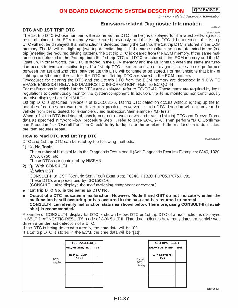
2) With CONSULT-IIWith GST
CONSULT-II or GST (Generic Scan Tool) Examples: P0340, P1320, P0705, P0750, etc.These DTCs are prescribed by ISO15031-6.(CONSULT-II also displays the malfunctioning component or system.)
I 1st trip DTC No. is the same as DTC No.I Output of a DTC indicates a malfunction. However, Mode II and GST do not indicate whether the
malfunction is still occurring or has occurred in the past and has returned to normal.CONSULT-II can identify malfunction status as shown below. Therefore, using CONSULT-II (if avail-able) is recommended.
A sample of CONSULT-II display for DTC is shown below. DTC or 1st trip DTC of a malfunction is displayedin SELF-DIAGNOSTIC RESULTS mode of CONSULT-II. Time data indicates how many times the vehicle wasdriven after the last detection of a DTC.If the DTC is being detected currently, the time data will be “0”.If a 1st trip DTC is stored in the ECM, the time data will be “[1t]”.
NEF065A
DTCdisplay
1st tripDTCdisplay
ON BOARD DIAGNOSTIC SYSTEM DESCRIPTION QG16I18DEEmission-related Diagnostic Information
EC-37
FREEZE FRAME DATA AND 1ST TRIP FREEZE FRAME DATANCEC0031S02
The ECM records the driving conditions such as fuel system status, calculated load value, engine coolanttemperature, short term fuel trim, long term fuel trim, engine speed, vehicle speed and absolute pressuresensor at the moment a malfunction is detected.Data which are stored in the ECM memory, along with the 1st trip DTC, are called 1st trip freeze frame data.The data, stored together with the DTC data, are called freeze frame data and displayed on CONSULT-II orGST. The 1st trip freeze frame data can only be displayed on the CONSULT-II screen, not on the GST. Fordetails, see EC-QG-58.Only one set of freeze frame data (either 1st trip freeze frame data or freeze frame data) can be stored in theECM. 1st trip freeze frame data is stored in the ECM memory along with the 1st trip DTC. There is no prior-ity for 1st trip freeze frame data and it is updated each time a different 1st trip DTC is detected. However, oncefreeze frame data (2nd trip detection/MI on) is stored in the ECM memory, 1st trip freeze frame data is nolonger stored. Remember, only one set of freeze frame data can be stored in the ECM. The ECM has the fol-lowing priorities to update the data.
Priority Items
1Freeze frame data Misfire — DTC: P0300 - P0304 (0300 - 0304)
Fuel Injection System Function — DTC: P0171 (0171), P0172 (0172)
2 Except the above items
3 1st trip freeze frame data
For example, the EGR malfunction (Priority: 2) was detected and the freeze frame data was stored in the 2ndtrip. After that when the misfire (Priority: 1) is detected in another trip, the freeze frame data will be updatedfrom the EGR malfunction to the misfire. The 1st trip freeze frame data is updated each time a different mal-function is detected. There is no priority for 1st trip freeze frame data. However, once freeze frame data isstored in the ECM memory, 1st trip freeze data is no longer stored (because only one freeze frame data or1st trip freeze frame data can be stored in the ECM). If freeze frame data is stored in the ECM memory andfreeze frame data with the same priority occurs later, the first (original) freeze frame data remains unchangedin the ECM memory.Both 1st trip freeze frame data and freeze frame data (along with the DTCs) are cleared when the ECMmemory is erased. Procedures for clearing the ECM memory are described in “HOW TO ERASE EMISSION-RELATED DIAGNOSTIC INFORMATION”. Refer to EC-QG-44.
SYSTEM READINESS TEST (SRT) CODENCEC0031S03
System Readiness Test (SRT) code is specified in Mode 1 of ISO15031-5. It indicates whether the self-diag-nostic tests for non-continuously monitored items have been completed or not.Inspection/Maintenance (I/M) tests of the on board diagnostic (OBD) II system may become the legal require-ments in some states/areas. All SRT codes must be set in this case. Unless all SRT codes are set, conduct-ing the I/M test may not be allowed.SRT codes are set after self-diagnosis has been performed one or more times. This occurs regardless ofwhether the diagnosis is in “OK” or “NG”, and whether or not the diagnosis is performed in consecutive trips.The following table lists the four SRT items (14 test items) for the ECM used in P11 models.
SRT items Self-diagnostic test items
Catalyst monitoring I Three way catalyst function P0420 (0420)
Oxygen sensor monitoring
I Heated oxygen sensor 1 (front) (Circuit) P0130 (0130)I Heated oxygen sensor 1 (front) (Lean shift monitoring) P0131 (0131)I Heated oxygen sensor 1 (front) (Rich shift monitoring) P0132 (0132)I Heated oxygen sensor 1 (front) (Response monitoring) P0133 (0133)I Heated oxygen sensor 1 (front) (High voltage) P0134 (0134)I Heated oxygen sensor 2 (rear) (Min. voltage monitoring) P0137 (0137)I Heated oxygen sensor 2 (rear) (Max. voltage monitoring) P0138 (0138)I Heated oxygen sensor 2 (rear) (Response monitoring) P0139 (0139)I Heated oxygen sensor 2 (rear) (High voltage) P0140 (0140)
Oxygen sensor heater monitoringI Heated oxygen sensor 1 (front) heater P0135 (0135)I Heated oxygen sensor 2 (rear) heater P0141 (0141)
EGR system monitoring(If so equipped)
I EGR function (Close) P0400 (0400)I EGR function (Open) P1402 (1402)
ON BOARD DIAGNOSTIC SYSTEM DESCRIPTION QG16I18DEEmission-related Diagnostic Information (Cont’d)
EC-38
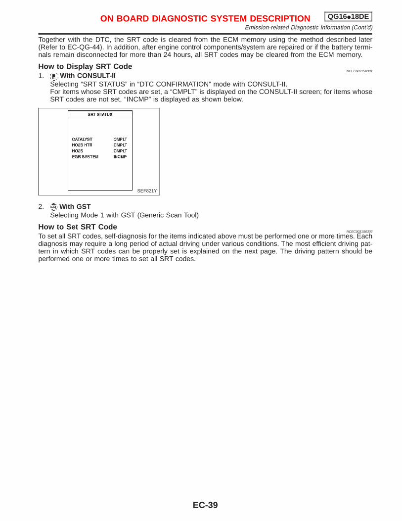
Together with the DTC, the SRT code is cleared from the ECM memory using the method described later(Refer to EC-QG-44). In addition, after engine control components/system are repaired or if the battery termi-nals remain disconnected for more than 24 hours, all SRT codes may be cleared from the ECM memory.
How to Display SRT CodeNCEC0031S0301
1. With CONSULT-IISelecting “SRT STATUS” in “DTC CONFIRMATION” mode with CONSULT-II.For items whose SRT codes are set, a “CMPLT” is displayed on the CONSULT-II screen; for items whoseSRT codes are not set, “INCMP” is displayed as shown below.
2. With GSTSelecting Mode 1 with GST (Generic Scan Tool)
How to Set SRT CodeNCEC0031S0302
To set all SRT codes, self-diagnosis for the items indicated above must be performed one or more times. Eachdiagnosis may require a long period of actual driving under various conditions. The most efficient driving pat-tern in which SRT codes can be properly set is explained on the next page. The driving pattern should beperformed one or more times to set all SRT codes.
SEF821Y
ON BOARD DIAGNOSTIC SYSTEM DESCRIPTION QG16I18DEEmission-related Diagnostic Information (Cont’d)
EC-39
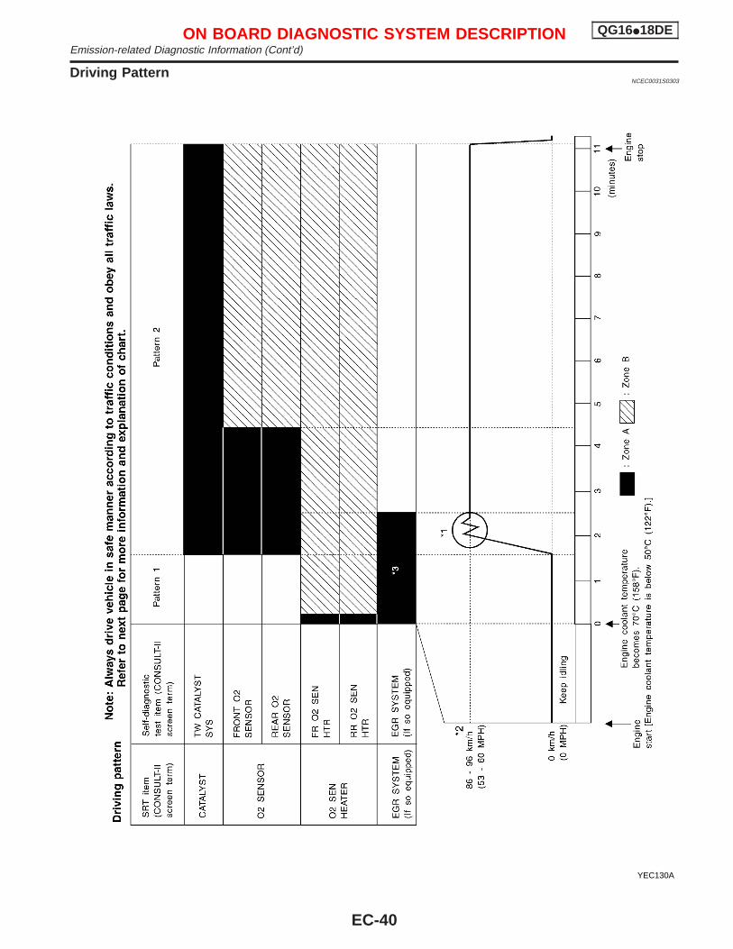
Driving PatternNCEC0031S0303
YEC130A
ON BOARD DIAGNOSTIC SYSTEM DESCRIPTION QG16I18DEEmission-related Diagnostic Information (Cont’d)
EC-40
I The time required for each diagnosis varies with road surface conditions, weather, altitude, individual driv-ing habits, etc.Zone A refers to the range where the time required, for the diagnosis under normal conditions*, is theshortest. Zone B refers to the range where the diagnosis can still be performed if the diagnosis is notcompleted within zone A.
*: Normal conditions refer to the following:− Sea level− Flat road− Ambient air temperature: 20 - 30°C (68 - 86°F)− Diagnosis is performed as quickly as possible under normal conditions.
Under different conditions [For example: ambient air temperature other than 20 - 30°C (68 - 86°F)], diagnosis mayalso be performed.
Pattern 1:I The engine is started at the engine coolant temperature of −10 to 35°C (14 to 95°F) (where the volt-
age between the ECM terminals 70 and 58 is 3.0 - 4.3V).I The engine must be operated at idle speed until the engine coolant temperature is greater than 70°C
(158°F) (where the voltage between the ECM terminals 70 and 58 is lower than 1.4V).Pattern 2:I When steady-state driving is performed again even after it is interrupted, each diagnosis can be conducted.
In this case, the time required for diagnosis may be extended.*1: Depress the accelerator pedal until vehicle speed is 90 km/h (56 MPH), then release the accelerator pedal
and keep it released for more than 10 seconds. Depress the accelerator pedal until vehicle speed is 90km/h (56 MPH) again.
*2: Checking the vehicle speed with CONSULT-II or GST is advised.*3: The driving pattern may be omitted when all the followings are performed using the “DTC WORK SUP-
PORT” mode with CONSULT-II.I “EGR SYSTEM P0400” (If so equipped)I “EGR SYSTEM P1402” (If so equipped)Suggested upshift speedsShown below are suggested vehicle speeds for shifting into a higher gear. These suggestions relate to fueleconomy and vehicle performance. Actual upshift speeds will vary according to road conditions, the weatherand individual driving habits.
Gear changeACCEL shift pointkm/h (MPH)
1st to 2nd 15 (9)
2nd to 3rd 35 (22)
3rd to 4th 50 (31)
4th to 5th 70 (43)
TEST VALUE AND TEST LIMIT (GST ONLY — NOT APPLICABLE TO CONSULT-II)NCEC0031S04
The following is the information specified in Mode 6 of ISO15031-5.The test value is a parameter used to determine whether a system/circuit diagnostic test is “OK” or “NG” whilebeing monitored by the ECM during self-diagnosis. The test limit is a reference value which is specified as themaximum or minimum value and is compared with the test value being monitored.Items for which these data (test value and test limit) are displayed are the same as SRT code items (6 testitems).These data (test value and test limit) are specified by Test ID (TID) and Component ID (CID) and can be dis-played on the GST screen.
X: Applicable —: Not applicable
SRT item Self-diagnostic test itemTest value (GST display)
Test limit ApplicationTID CID
CATALYST Three way catalyst function01H 01H Max. X
02H 81H Min. X
ON BOARD DIAGNOSTIC SYSTEM DESCRIPTION QG16I18DEEmission-related Diagnostic Information (Cont’d)
EC-41
SRT item Self-diagnostic test itemTest value (GST display)
Test limit ApplicationTID CID
HO2S
Heated oxygen sensor 1(front)
09H 04H Max. X
0AH 84H Min. X
0BH 04H Max. X
0CH 04H Max. X
0DH 04H Max. X
Heated oxygen sensor 2(rear)
19H 86H Min. X
1AH 86H Min. X
1BH 06H Max. X
1CH 06H Max. X
HO2S HTR
Heated oxygen sensor 1(front) heater
29H 08H Max. X
2AH 88H Min. X
Heated oxygen sensor 2(rear) heater
2DH 0AH Max. X
2EH 8AH Min. X
EGR SYSTEM(If so equipped)
EGR function(If so equipped)
31H 8CH Min. X
32H 8CH Min. X
33H 8CH Min. X
34H 8CH Min. X
35H 0CH Max. X
EMISSION-RELATED DIAGNOSTIC INFORMATION ITEMSNCEC0031S05
X: Applicable —: Not applicable
Items(CONSULT-II screen terms)
DTC*4
SRT codeTest value/Test
limit(GST only)
1st trip DTC*4Reference
pageCONSULT-IIGST*2
ECM*1
NO SELF DIAGNOSTICFAILURE INDICATED
P0000 0000 — — — —
MAF SEN/CIRCUIT P0100 0100 — — X EC-QG-110
AIR TEMP SEN/CIRC P0110 0110 — — X EC-QG-116
COOLANT T SEN/CIRC P0115 0115 — — X EC-QG-120
THRTL POS SEN/CIRC P0120 0120 — — X EC-QG-125
HO2S1 (B1)*5 P0130 0130 X X X*3 EC-QG-132
HO2S1 (B1)*5 P0131 0131 X X X*3 EC-QG-139
HO2S1 (B1)*5 P0132 0132 X X X*3 EC-QG-145
HO2S1 (B1)*5 P0133 0133 X X X*3 EC-QG-151
HO2S1 (B1)*5 P0134 0134 X X X*3 EC-QG-160
HO2S1 HTR (B1)*5 P0135 0135 X X X*3 EC-QG-166
HO2S2 (B1)*5 P0137 0137 X X X*3 EC-QG-171
HO2S2 (B1)*5 P0138 0138 X X X*3 EC-QG-180
HO2S2 (B1)*5 P0139 0139 X X X*3 EC-QG-188
ON BOARD DIAGNOSTIC SYSTEM DESCRIPTION QG16I18DEEmission-related Diagnostic Information (Cont’d)
EC-42
Items(CONSULT-II screen terms)
DTC*4
SRT codeTest value/Test
limit(GST only)
1st trip DTC*4Reference
pageCONSULT-IIGST*2
ECM*1
HO2S2 (B1)*5 P0140 0140 X X X*3 EC-QG-197
HO2S2 HTR (B1)*5 P0141 0141 X X X*3 EC-QG-203
FUEL SYS LEAN/BK1*5 P0171 0171 — — X EC-QG-208
FUEL SYS RICH/BK1*5 P0172 0172 — — X EC-QG-215
MULTI CYL MISFIRE*5 P0300 0300 — — X EC-QG-222
CYL 1 MISFIRE*5 P0301 0301 — — X EC-QG-222
CYL 2 MISFIRE*5 P0302 0302 — — X EC-QG-222
CYL 3 MISFIRE*5 P0303 0303 — — X EC-QG-222
CYL 4 MISFIRE*5 P0304 0304 — — X EC-QG-222
KNOCK SEN/CIRC-B1 P0325 0325 — — — EC-QG-228
CKP SEN/CIRCUIT *5 P0335 0335 — — X EC-QG-232
CMP SEN/CIRCUIT P0340 0340 — — X EC-QG-238
EGR SYSTEM*5*6 P0400 0400 X X X*3 EC-QG-244
EGR VOL CON/V CIR*5*6 P0403 0403 — — X EC-QG-252
TW CATALYST SYS-B1*5 P0420 0420 X X X*3 EC-QG-258
PURG VOLUME CONT/V*5 P0443 0443 — — X EC-QG-262
VEH SPEED SEN/CIRC P0500 0500 — — X EC-QG-267
IACV/AAC VLV/CIRC*5 P0505 0505 — — X EC-QG-274
ECM P0605 0605 — — X EC-QG-282
INT/V TIM V/CIR-B1*5 P1111 1111 — — X EC-QG-284
ENG OVER TEMP P1217 1217 — — X EC-QG-289
EGR TEMP SEN/CIRC*5*6 P1401 1401 — — X EC-QG-300
EGR SYSTEM*5*6 P1402 1402 X X X*3 EC-QG-305
P-N POS SW/CIRCUIT*5 P1706 1706 — — X EC-QG-313
*1: In Diagnostic Test Mode II (Self-diagnostic results). These numbers are controlled by NISSAN.*2: These numbers are prescribed by ISO15031-6.*3: These are not displayed with GST.*4: 1st trip DTC No. is the same as DTC No.*5: Not available for “Eastern Europe model”.*6: If so equipped
ON BOARD DIAGNOSTIC SYSTEM DESCRIPTION QG16I18DEEmission-related Diagnostic Information (Cont’d)
EC-43
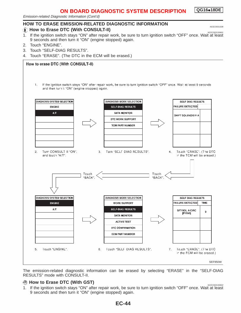
HOW TO ERASE EMISSION-RELATED DIAGNOSTIC INFORMATIONNCEC0031S06
How to Erase DTC (With CONSULT-II)NCEC0031S0601
1. If the ignition switch stays “ON” after repair work, be sure to turn ignition switch “OFF” once. Wait at least9 seconds and then turn it “ON” (engine stopped) again.
2. Touch “ENGINE”.3. Touch “SELF-DIAG RESULTS”.4. Touch “ERASE”. (The DTC in the ECM will be erased.)
The emission-related diagnostic information can be erased by selecting “ERASE” in the “SELF-DIAGRESULTS” mode with CONSULT-II.
How to Erase DTC (With GST)NCEC0031S0602
1. If the ignition switch stays “ON” after repair work, be sure to turn ignition switch “OFF” once. Wait at least9 seconds and then turn it “ON” (engine stopped) again.
SEF950W
ON BOARD DIAGNOSTIC SYSTEM DESCRIPTION QG16I18DEEmission-related Diagnostic Information (Cont’d)
EC-44
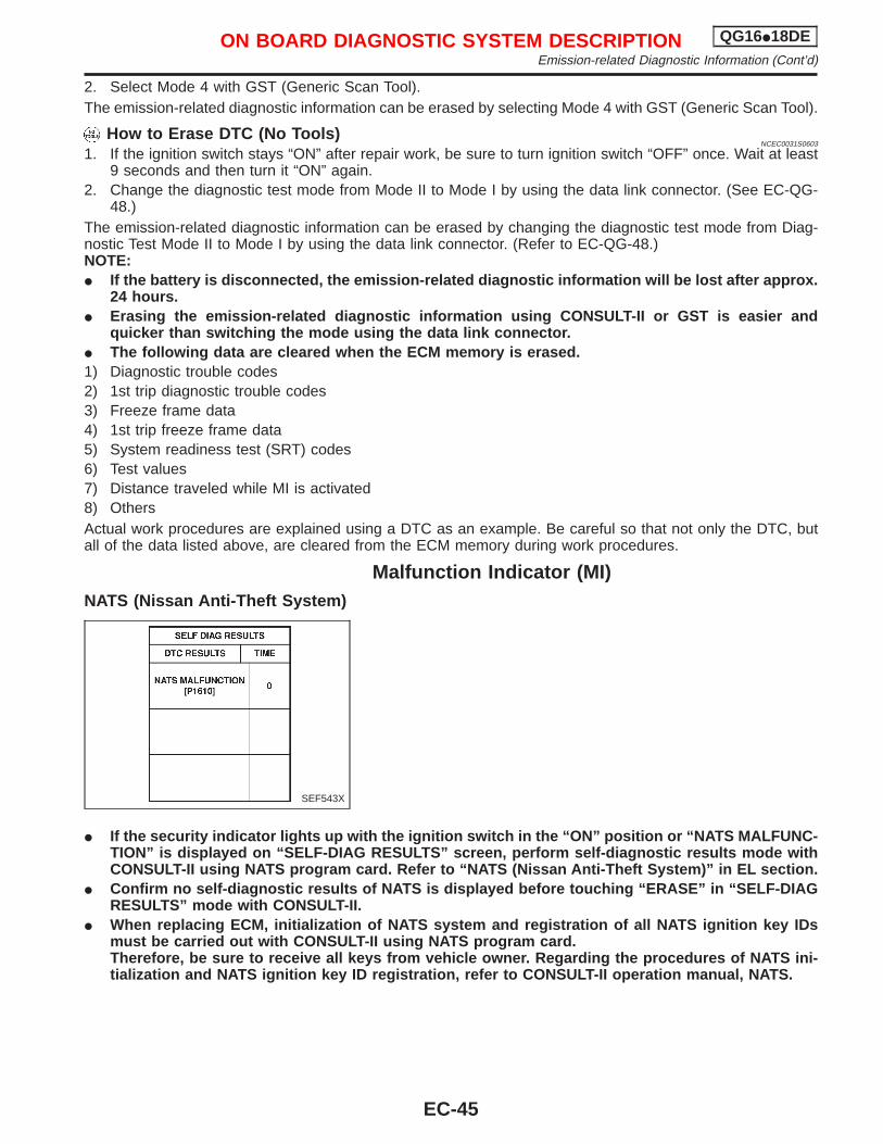
2. Select Mode 4 with GST (Generic Scan Tool).The emission-related diagnostic information can be erased by selecting Mode 4 with GST (Generic Scan Tool).
How to Erase DTC (No Tools)NCEC0031S0603
1. If the ignition switch stays “ON” after repair work, be sure to turn ignition switch “OFF” once. Wait at least9 seconds and then turn it “ON” again.
2. Change the diagnostic test mode from Mode II to Mode I by using the data link connector. (See EC-QG-48.)
The emission-related diagnostic information can be erased by changing the diagnostic test mode from Diag-nostic Test Mode II to Mode I by using the data link connector. (Refer to EC-QG-48.)NOTE:I If the battery is disconnected, the emission-related diagnostic information will be lost after approx.
24 hours.I Erasing the emission-related diagnostic information using CONSULT-II or GST is easier and
quicker than switching the mode using the data link connector.I The following data are cleared when the ECM memory is erased.1) Diagnostic trouble codes2) 1st trip diagnostic trouble codes3) Freeze frame data4) 1st trip freeze frame data5) System readiness test (SRT) codes6) Test values7) Distance traveled while MI is activated8) OthersActual work procedures are explained using a DTC as an example. Be careful so that not only the DTC, butall of the data listed above, are cleared from the ECM memory during work procedures.
Malfunction Indicator (MI)NATS (Nissan Anti-Theft System)
I If the security indicator lights up with the ignition switch in the “ON” position or “NATS MALFUNC-TION” is displayed on “SELF-DIAG RESULTS” screen, perform self-diagnostic results mode withCONSULT-II using NATS program card. Refer to “NATS (Nissan Anti-Theft System)” in EL section.
I Confirm no self-diagnostic results of NATS is displayed before touching “ERASE” in “SELF-DIAGRESULTS” mode with CONSULT-II.
I When replacing ECM, initialization of NATS system and registration of all NATS ignition key IDsmust be carried out with CONSULT-II using NATS program card.Therefore, be sure to receive all keys from vehicle owner. Regarding the procedures of NATS ini-tialization and NATS ignition key ID registration, refer to CONSULT-II operation manual, NATS.
SEF543X
ON BOARD DIAGNOSTIC SYSTEM DESCRIPTION QG16I18DEEmission-related Diagnostic Information (Cont’d)
EC-45
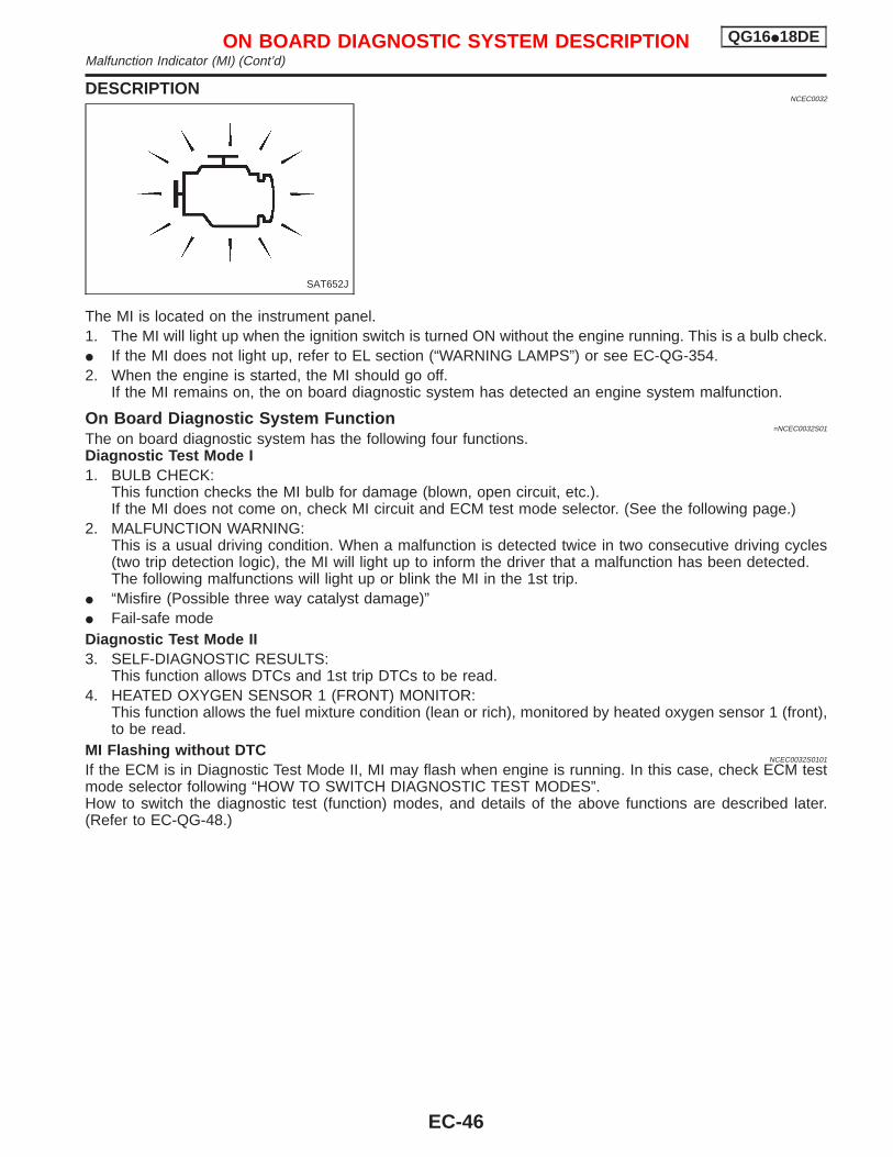
DESCRIPTIONNCEC0032
The MI is located on the instrument panel.1. The MI will light up when the ignition switch is turned ON without the engine running. This is a bulb check.I If the MI does not light up, refer to EL section (“WARNING LAMPS”) or see EC-QG-354.2. When the engine is started, the MI should go off.
If the MI remains on, the on board diagnostic system has detected an engine system malfunction.
On Board Diagnostic System Function=NCEC0032S01
The on board diagnostic system has the following four functions.Diagnostic Test Mode I1. BULB CHECK:
This function checks the MI bulb for damage (blown, open circuit, etc.).If the MI does not come on, check MI circuit and ECM test mode selector. (See the following page.)
2. MALFUNCTION WARNING:This is a usual driving condition. When a malfunction is detected twice in two consecutive driving cycles(two trip detection logic), the MI will light up to inform the driver that a malfunction has been detected.The following malfunctions will light up or blink the MI in the 1st trip.
I “Misfire (Possible three way catalyst damage)”I Fail-safe modeDiagnostic Test Mode II3. SELF-DIAGNOSTIC RESULTS:
This function allows DTCs and 1st trip DTCs to be read.4. HEATED OXYGEN SENSOR 1 (FRONT) MONITOR:
This function allows the fuel mixture condition (lean or rich), monitored by heated oxygen sensor 1 (front),to be read.
MI Flashing without DTCNCEC0032S0101
If the ECM is in Diagnostic Test Mode II, MI may flash when engine is running. In this case, check ECM testmode selector following “HOW TO SWITCH DIAGNOSTIC TEST MODES”.How to switch the diagnostic test (function) modes, and details of the above functions are described later.(Refer to EC-QG-48.)
SAT652J
ON BOARD DIAGNOSTIC SYSTEM DESCRIPTION QG16I18DEMalfunction Indicator (MI) (Cont’d)
EC-46
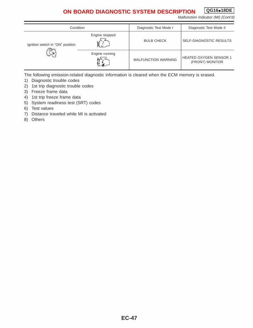
Condition Diagnostic Test Mode I Diagnostic Test Mode II
Ignition switch in “ON” position
Engine stopped
BULB CHECK SELF-DIAGNOSTIC RESULTS
Engine running
MALFUNCTION WARNINGHEATED OXYGEN SENSOR 1
(FRONT) MONITOR
The following emission-related diagnostic information is cleared when the ECM memory is erased.1) Diagnostic trouble codes2) 1st trip diagnostic trouble codes3) Freeze frame data4) 1st trip freeze frame data5) System readiness test (SRT) codes6) Test values7) Distance traveled while MI is activated8) Others
ON BOARD DIAGNOSTIC SYSTEM DESCRIPTION QG16I18DEMalfunction Indicator (MI) (Cont’d)
EC-47
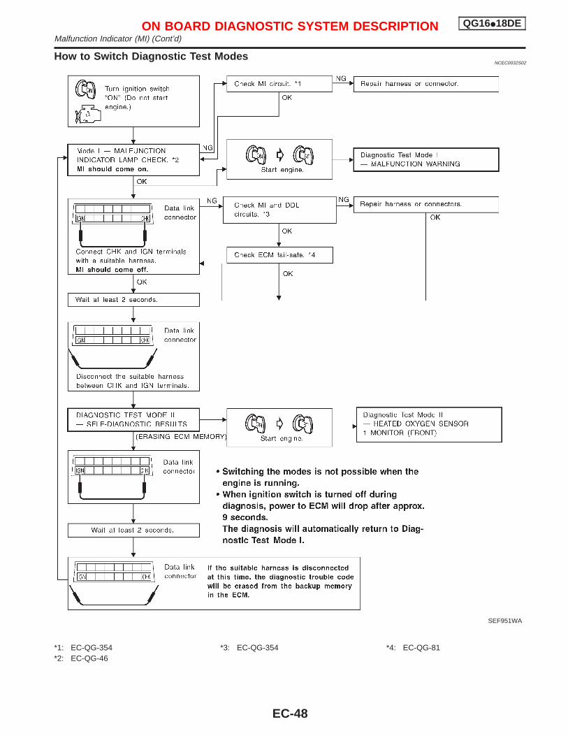
How to Switch Diagnostic Test ModesNCEC0032S02
*1: EC-QG-354*2: EC-QG-46
*3: EC-QG-354 *4: EC-QG-81
SEF951WA
ON BOARD DIAGNOSTIC SYSTEM DESCRIPTION QG16I18DEMalfunction Indicator (MI) (Cont’d)
EC-48
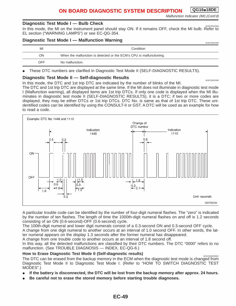
Diagnostic Test Mod e I — Bulb CheckNCEC0032S03
In this mode, the MI on the instrument panel should stay ON. If it remains OFF, check the MI bulb. Refer toEL section (“WARNING LAMPS”) or see EC-QG-354.
Diagnostic Test Mod e I — Malfunction WarningNCEC0032S04
MI Condition
ON When the malfunction is detected or the ECM’s CPU is malfunctioning.
OFF No malfunction.
I These DTC numbers are clarified in Diagnostic Test Mode II (SELF-DIAGNOSTIC RESULTS).
Diagnostic Test Mode II — Self-diagnostic ResultsNCEC0032S05
In this mode, the DTC and 1st trip DTC are indicated by the number of blinks of the MI.The DTC and 1st trip DTC are displayed at the same time. If the MI does not illuminate in diagnostic test modeI (Malfunction warning), all displayed items are 1st trip DTCs. If only one code is displayed when the MI illu-minates in diagnostic test mode II (SELF-DIAGNOSTIC RESULTS), it is a DTC; if two or more codes aredisplayed, they may be either DTCs or 1st trip DTCs. DTC No. is same as that of 1st trip DTC. These uni-dentified codes can be identified by using the CONSULT-II or GST. A DTC will be used as an example for howto read a code.
A particular trouble code can be identified by the number of four-digit numeral flashes. The “zero” is indicatedby the number of ten flashes. The length of time the 1000th-digit numeral flashes on and off is 1.2 secondsconsisting of an ON (0.6-second)-OFF (0.6-second) cycle.The 100th-digit numeral and lower digit numerals consist of a 0.3-second ON and 0.3-second OFF cycle.A change from one digit numeral to another occurs at an interval of 1.0 second OFF. In other words, the lat-ter numeral appears on the display 1.3 seconds after the former numeral has disappeared.A change from one trouble code to another occurs at an interval of 1.8 second off.In this way, all the detected malfunctions are classified by their DTC numbers. The DTC “0000” refers to nomalfunction. (See TROUBLE DIAGNOSIS — INDEX, EC-QG-6.)How to Erase Diagnostic Test Mode II (Self-diagnostic results)
NCEC0032S0501
The DTC can be erased from the backup memory in the ECM when the diagnostic test mode is changed fromDiagnostic Test Mode II to Diagnostic Test Mode I. (Refer to “HOW TO SWITCH DIAGNOSTIC TESTMODES”.)I If the battery is disconnected, the DTC will be lost from the backup memory after approx. 24 hours.I Be careful not to erase the stored memory before starting trouble diagnoses.
SEF952W
ON BOARD DIAGNOSTIC SYSTEM DESCRIPTION QG16I18DEMalfunction Indicator (MI) (Cont’d)
EC-49
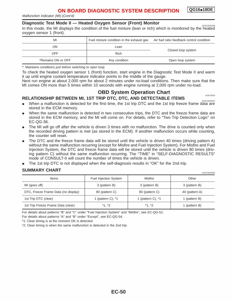
Diagnostic Test Mode II — Heated Oxygen Sensor (Front) MonitorNCEC0032S06
In this mode, the MI displays the condition of the fuel mixture (lean or rich) which is monitored by the heatedoxygen sensor 1 (front).
MI Fuel mixture condition in the exhaust gas Air fuel ratio feedback control condition
ON LeanClosed loop system
OFF Rich
*Remains ON or OFF Any condition Open loop system
*: Maintains conditions just before switching to open loop.
To check the heated oxygen sensor 1 (front) function, start engine in the Diagnostic Test Mode II and warmit up until engine coolant temperature indicator points to the middle of the gauge.Next run engine at about 2,000 rpm for about 2 minutes under no-load conditions. Then make sure that theMI comes ON more than 5 times within 10 seconds with engine running at 2,000 rpm under no-load.
OBD System Operation ChartNCEC0033
RELATIONSHIP BETWEEN MI, 1ST TRIP DTC, DTC, AND DETECTABLE ITEMSNCEC0033S01
I When a malfunction is detected for the first time, the 1st trip DTC and the 1st trip freeze frame data arestored in the ECM memory.
I When the same malfunction is detected in two consecutive trips, the DTC and the freeze frame data arestored in the ECM memory, and the MI will come on. For details, refer to “Two Trip Detection Logic” onEC-QG-36.
I The MI will go off after the vehicle is driven 3 times with no malfunction. The drive is counted only whenthe recorded driving pattern is met (as stored in the ECM). If another malfunction occurs while counting,the counter will reset.
I The DTC and the freeze frame data will be stored until the vehicle is driven 40 times (driving pattern A)without the same malfunction recurring (except for Misfire and Fuel Injection System). For Misfire and FuelInjection System, the DTC and freeze frame data will be stored until the vehicle is driven 80 times (driv-ing pattern C) without the same malfunction recurring. The “TIME” in “SELF-DIAGNOSTIC RESULTS”mode of CONSULT-II will count the number of times the vehicle is driven.
I The 1st trip DTC is not displayed when the self-diagnosis results in “OK” for the 2nd trip.
SUMMARY CHARTNCEC0033S02
Items Fuel Injection System Misfire Other
MI (goes off) 3 (pattern B) 3 (pattern B) 3 (pattern B)
DTC, Freeze Frame Data (no display) 80 (pattern C) 80 (pattern C) 40 (pattern A)
1st Trip DTC (clear) 1 (pattern C), *1 1 (pattern C), *1 1 (pattern B)
1st Trip Freeze Frame Data (clear) *1, *2 *1, *2 1 (pattern B)
For details about patterns “B” and “C” under “Fuel Injection System” and “Misfire”, see EC-QG-52.For details about patterns “A” and “B” under “Except”, see EC-QG-54.*1: Clear timing is at the moment OK is detected.*2: Clear timing is when the same malfunction is detected in the 2nd trip.
ON BOARD DIAGNOSTIC SYSTEM DESCRIPTION QG16I18DEMalfunction Indicator (MI) (Cont’d)
EC-50
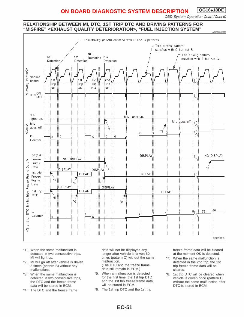
RELATIONSHIP BETWEEN MI, DTC, 1ST TRIP DTC AND DRIVING PATTERNS FOR“MISFIRE” <EXHAUST QUALITY DETERIORATION>, “FUEL INJECTION SYSTEM”
NCEC0033S03
*1: When the same malfunction isdetected in two consecutive trips,MI will light up.
*2: MI will go off after vehicle is driven3 times (pattern B) without anymalfunctions.
*3: When the same malfunction isdetected in two consecutive trips,the DTC and the freeze framedata will be stored in ECM.
*4: The DTC and the freeze frame
data will not be displayed anylonger after vehicle is driven 80times (pattern C) without the samemalfunction.(The DTC and the freeze framedata still remain in ECM.)
*5: When a malfunction is detectedfor the first time, the 1st trip DTCand the 1st trip freeze frame datawill be stored in ECM.
*6: The 1st trip DTC and the 1st trip
freeze frame data will be clearedat the moment OK is detected.
*7: When the same malfunction isdetected in the 2nd trip, the 1sttrip freeze frame data will becleared.
*8: 1st trip DTC will be cleared whenvehicle is driven once (pattern C)without the same malfunction afterDTC is stored in ECM.
SEF392S
ON BOARD DIAGNOSTIC SYSTEM DESCRIPTION QG16I18DEOBD System Operation Chart (Cont’d)
EC-51
EXPLANATION FOR DRIVING PATTERNS FOR “MISFIRE <EXHAUST QUALITYDETERIORATION>”, “FUEL INJECTION SYSTEM”
NCEC0033S04
Driving Pattern BNCEC0033S0401
Driving pattern B means the vehicle operation as follows:All components and systems should be monitored at least once by the OBD system.I The B counter will be cleared when the malfunction is detected once regardless of the driving pattern.I The B counter will be counted up when driving pattern B is satisfied without any malfunction.I The MI will go off when the B counter reaches 3. (*2 in EC-QG-51)
Driving Pattern CNCEC0033S0402
Driving pattern C means the vehicle operation as follows:1) The following conditions should be satisfied at the same time:
Engine speed: (Engine speed in the freeze frame data) ±375 rpmCalculated load value: (Calculated load value in the freeze frame data) × (1±0.1) [%]Engine coolant temperature (T) condition:
I When the freeze frame data shows lower than 70°C (158°F), “T” should be lower than 70°C (158°F).I When the freeze frame data shows higher than or equal to 70°C (158°F), “T” should be higher than or
equal to 70°C (158°F).Example:If the stored freeze frame data is as follows:Engine speed: 850 rpm, Calculated load value: 30%, Engine coolant temperature: 80°C (176°F)To be satisfied with driving pattern C, the vehicle should run under the following conditions:Engine speed: 475 - 1,225 rpm, Calculated load value: 27 - 33%, Engine coolant temperature: more than 70°C(158°F)I The C counter will be cleared when the malfunction is detected regardless of driving pattern C.I The C counter will be counted up when driving pattern C is satisfied without the same malfunction.I The DTC will not be displayed after C counter reaches 80.I The 1st trip DTC will be cleared when C counter is counted once without the same malfunction after DTC
is stored in ECM.
ON BOARD DIAGNOSTIC SYSTEM DESCRIPTION QG16I18DEOBD System Operation Chart (Cont’d)
EC-52
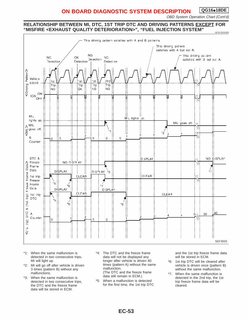
RELATIONSHIP BETWEEN MI, DTC, 1ST TRIP DTC AND DRIVING PATTERNS EXCEPT FOR“MISFIRE <EXHAUST QUALITY DETERIORATION>”, “FUEL INJECTION SYSTEM”
NCEC0033S05
*1: When the same malfunction isdetected in two consecutive trips,MI will light up.
*2: MI will go off after vehicle is driven3 times (pattern B) without anymalfunctions.
*3: When the same malfunction isdetected in two consecutive trips,the DTC and the freeze framedata will be stored in ECM.
*4: The DTC and the freeze framedata will not be displayed anylonger after vehicle is driven 40times (pattern A) without the samemalfunction.(The DTC and the freeze framedata still remain in ECM.)
*5: When a malfunction is detectedfor the first time, the 1st trip DTC
and the 1st trip freeze frame datawill be stored in ECM.
*6: 1st trip DTC will be cleared aftervehicle is driven once (pattern B)without the same malfunction.
*7: When the same malfunction isdetected in the 2nd trip, the 1sttrip freeze frame data will becleared.
SEF393S
ON BOARD DIAGNOSTIC SYSTEM DESCRIPTION QG16I18DEOBD System Operation Chart (Cont’d)
EC-53
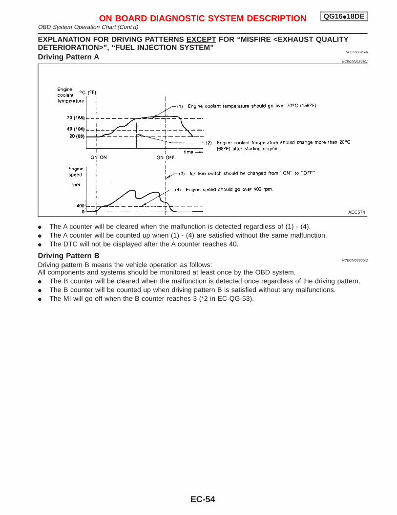
EXPLANATION FOR DRIVING PATTERNS EXCEPT FOR “MISFIRE <EXHAUST QUALITYDETERIORATION>”, “FUEL INJECTION SYSTEM”
NCEC0033S06
Driving Pattern ANCEC0033S0601
I The A counter will be cleared when the malfunction is detected regardless of (1) - (4).I The A counter will be counted up when (1) - (4) are satisfied without the same malfunction.I The DTC will not be displayed after the A counter reaches 40.
Driving Pattern BNCEC0033S0602
Driving pattern B means the vehicle operation as follows:All components and systems should be monitored at least once by the OBD system.I The B counter will be cleared when the malfunction is detected once regardless of the driving pattern.I The B counter will be counted up when driving pattern B is satisfied without any malfunctions.I The MI will go off when the B counter reaches 3 (*2 in EC-QG-53).
AEC574
ON BOARD DIAGNOSTIC SYSTEM DESCRIPTION QG16I18DEOBD System Operation Chart (Cont’d)
EC-54
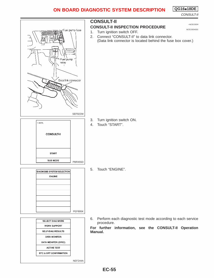
CONSULT-II=NCEC0034
CONSULT-II INSPECTION PROCEDURENCEC0034S01
1. Turn ignition switch OFF.2. Connect “CONSULT-II” to data link connector.
(Data link connector is located behind the fuse box cover.)
3. Turn ignition switch ON.4. Touch “START”.
5. Touch “ENGINE”.
6. Perform each diagnostic test mode according to each serviceprocedure.
For further information, see the CONSULT-II OperationManual.
SEF922W
PBR455D
PEF895K
NEF244A
ON BOARD DIAGNOSTIC SYSTEM DESCRIPTION QG16I18DECONSULT-II
EC-55
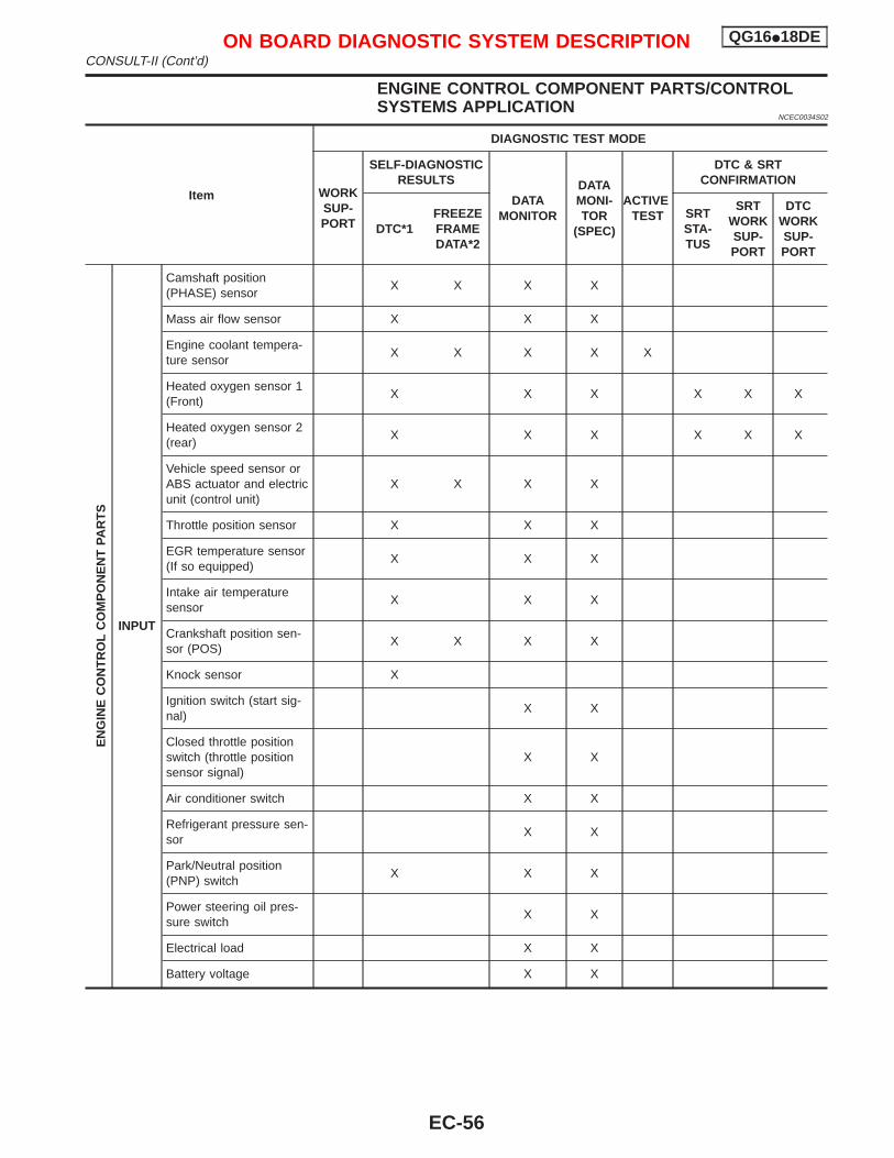
ENGINE CONTROL COMPONENT PARTS/CONTROLSYSTEMS APPLICATION
NCEC0034S02
Item
DIAGNOSTIC TEST MODE
WORKSUP-PORT
SELF-DIAGNOSTICRESULTS
DATAMONITOR
DATAMONI-TOR
(SPEC)
ACTIVETEST
DTC & SRTCONFIRMATION
DTC*1FREEZEFRAMEDATA*2
SRTSTA-TUS
SRTWORKSUP-PORT
DTCWORKSUP-PORT
EN
GIN
EC
ON
TR
OL
CO
MP
ON
EN
TPA
RT
S
INPUT
Camshaft position(PHASE) sensor
X X X X
Mass air flow sensor X X X
Engine coolant tempera-ture sensor
X X X X X
Heated oxygen sensor 1(Front)
X X X X X X
Heated oxygen sensor 2(rear)
X X X X X X
Vehicle speed sensor orABS actuator and electricunit (control unit)
X X X X
Throttle position sensor X X X
EGR temperature sensor(If so equipped)
X X X
Intake air temperaturesensor
X X X
Crankshaft position sen-sor (POS)
X X X X
Knock sensor X
Ignition switch (start sig-nal)
X X
Closed throttle positionswitch (throttle positionsensor signal)
X X
Air conditioner switch X X
Refrigerant pressure sen-sor
X X
Park/Neutral position(PNP) switch
X X X
Power steering oil pres-sure switch
X X
Electrical load X X
Battery voltage X X
ON BOARD DIAGNOSTIC SYSTEM DESCRIPTION QG16I18DECONSULT-II (Cont’d)
EC-56
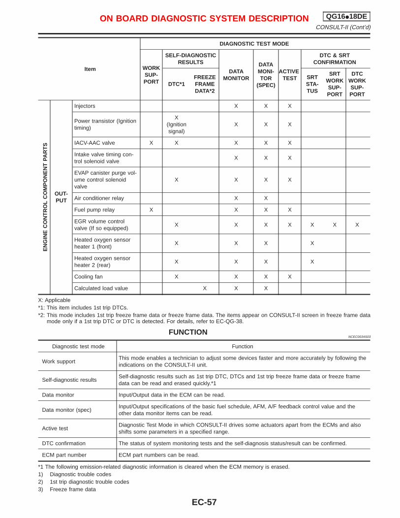
Item
DIAGNOSTIC TEST MODE
WORKSUP-PORT
SELF-DIAGNOSTICRESULTS
DATAMONITOR
DATAMONI-TOR
(SPEC)
ACTIVETEST
DTC & SRTCONFIRMATION
DTC*1FREEZEFRAMEDATA*2
SRTSTA-TUS
SRTWORKSUP-PORT
DTCWORKSUP-PORT
EN
GIN
EC
ON
TR
OL
CO
MP
ON
EN
TPA
RT
S
OUT-PUT
Injectors X X X
Power transistor (Ignitiontiming)
X(Ignitionsignal)
X X X
IACV-AAC valve X X X X X
Intake valve timing con-trol solenoid valve
X X X
EVAP canister purge vol-ume control solenoidvalve
X X X X
Air conditioner relay X X
Fuel pump relay X X X X
EGR volume controlvalve (If so equipped)
X X X X X X X
Heated oxygen sensorheater 1 (front)
X X X X
Heated oxygen sensorheater 2 (rear)
X X X X
Cooling fan X X X X
Calculated load value X X X
X: Applicable*1: This item includes 1st trip DTCs.*2: This mode includes 1st trip freeze frame data or freeze frame data. The items appear on CONSULT-II screen in freeze frame data
mode only if a 1st trip DTC or DTC is detected. For details, refer to EC-QG-38.
FUNCTIONNCEC0034S03
Diagnostic test mode Function
Work supportThis mode enables a technician to adjust some devices faster and more accurately by following theindications on the CONSULT-II unit.
Self-diagnostic resultsSelf-diagnostic results such as 1st trip DTC, DTCs and 1st trip freeze frame data or freeze framedata can be read and erased quickly.*1
Data monitor Input/Output data in the ECM can be read.
Data monitor (spec)Input/Output specifications of the basic fuel schedule, AFM, A/F feedback control value and theother data monitor items can be read.
Active testDiagnostic Test Mode in which CONSULT-II drives some actuators apart from the ECMs and alsoshifts some parameters in a specified range.
DTC confirmation The status of system monitoring tests and the self-diagnosis status/result can be confirmed.
ECM part number ECM part numbers can be read.
*1 The following emission-related diagnostic information is cleared when the ECM memory is erased.1) Diagnostic trouble codes2) 1st trip diagnostic trouble codes3) Freeze frame data
ON BOARD DIAGNOSTIC SYSTEM DESCRIPTION QG16I18DECONSULT-II (Cont’d)
EC-57
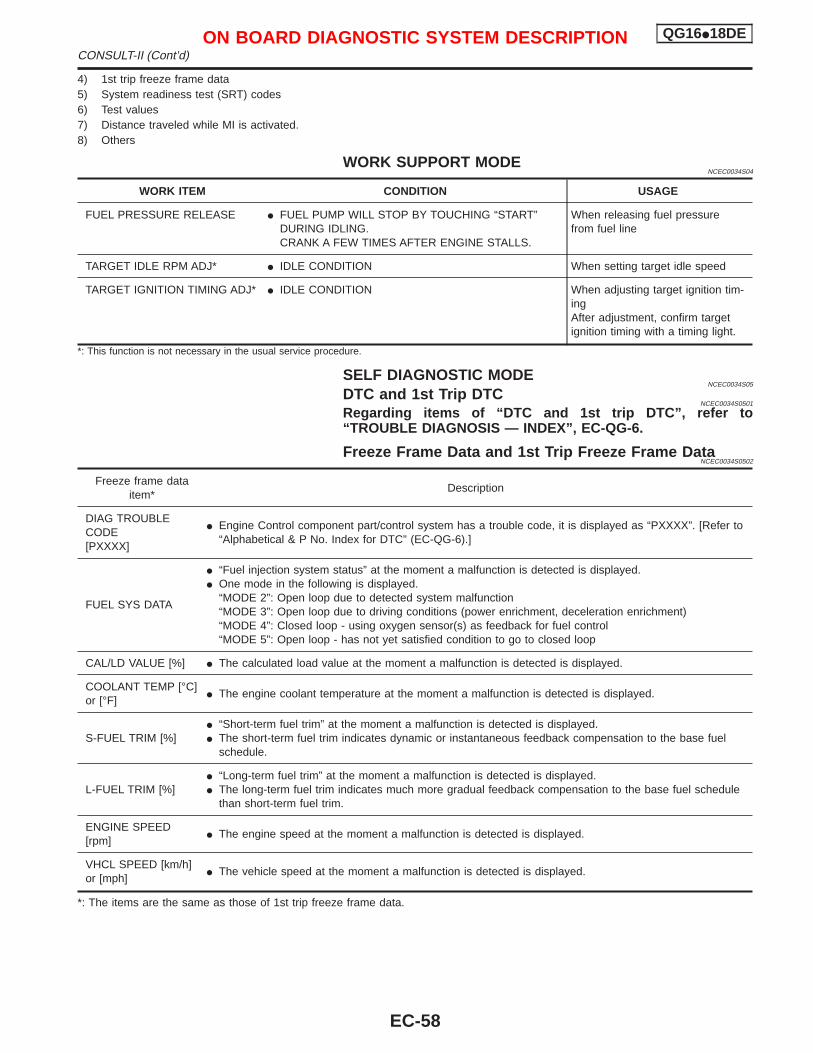
4) 1st trip freeze frame data5) System readiness test (SRT) codes6) Test values7) Distance traveled while MI is activated.8) Others
WORK SUPPORT MODENCEC0034S04
WORK ITEM CONDITION USAGE
FUEL PRESSURE RELEASE I FUEL PUMP WILL STOP BY TOUCHING “START”DURING IDLING.CRANK A FEW TIMES AFTER ENGINE STALLS.
When releasing fuel pressurefrom fuel line
TARGET IDLE RPM ADJ* I IDLE CONDITION When setting target idle speed
TARGET IGNITION TIMING ADJ* I IDLE CONDITION When adjusting target ignition tim-ingAfter adjustment, confirm targetignition timing with a timing light.
*: This function is not necessary in the usual service procedure.
SELF DIAGNOSTIC MODENCEC0034S05
DTC and 1st Trip DTCNCEC0034S0501
Regarding items of “DTC and 1st trip DTC”, refer to“TROUBLE DIAGNOSIS — INDEX”, EC-QG-6.
Freeze Frame Data and 1st Trip Freeze Frame DataNCEC0034S0502
Freeze frame dataitem*
Description
DIAG TROUBLECODE[PXXXX]
I Engine Control component part/control system has a trouble code, it is displayed as “PXXXX”. [Refer to“Alphabetical & P No. Index for DTC” (EC-QG-6).]
FUEL SYS DATA
I “Fuel injection system status” at the moment a malfunction is detected is displayed.I One mode in the following is displayed.
“MODE 2”: Open loop due to detected system malfunction“MODE 3”: Open loop due to driving conditions (power enrichment, deceleration enrichment)“MODE 4”: Closed loop - using oxygen sensor(s) as feedback for fuel control“MODE 5”: Open loop - has not yet satisfied condition to go to closed loop
CAL/LD VALUE [%] I The calculated load value at the moment a malfunction is detected is displayed.
COOLANT TEMP [°C]or [°F]
I The engine coolant temperature at the moment a malfunction is detected is displayed.
S-FUEL TRIM [%]I “Short-term fuel trim” at the moment a malfunction is detected is displayed.I The short-term fuel trim indicates dynamic or instantaneous feedback compensation to the base fuel
schedule.
L-FUEL TRIM [%]I “Long-term fuel trim” at the moment a malfunction is detected is displayed.I The long-term fuel trim indicates much more gradual feedback compensation to the base fuel schedule
than short-term fuel trim.
ENGINE SPEED[rpm]
I The engine speed at the moment a malfunction is detected is displayed.
VHCL SPEED [km/h]or [mph]
I The vehicle speed at the moment a malfunction is detected is displayed.
*: The items are the same as those of 1st trip freeze frame data.
ON BOARD DIAGNOSTIC SYSTEM DESCRIPTION QG16I18DECONSULT-II (Cont’d)
EC-58
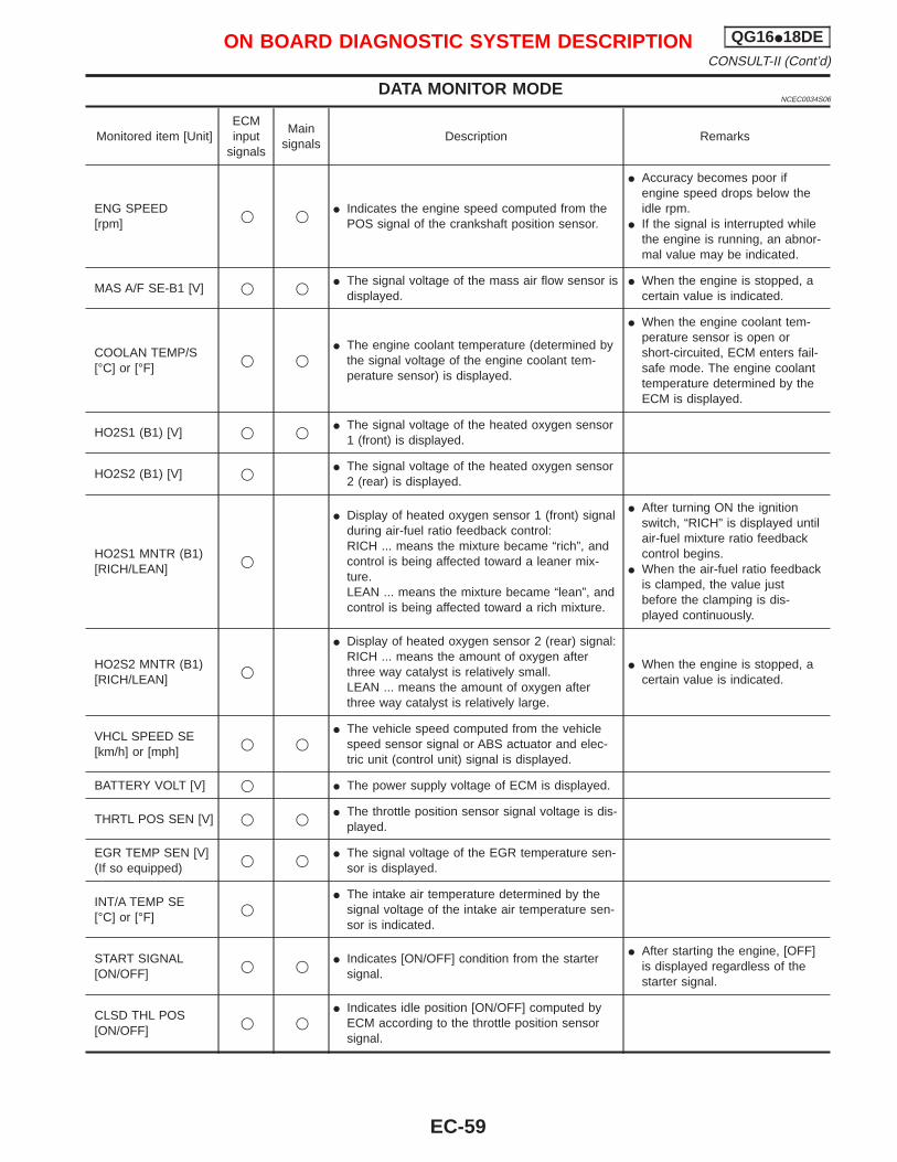
DATA MONITOR MODENCEC0034S06
Monitored item [Unit]ECMinput
signals
Mainsignals
Description Remarks
ENG SPEED[rpm]
q q I Indicates the engine speed computed from thePOS signal of the crankshaft position sensor.
I Accuracy becomes poor ifengine speed drops below theidle rpm.
I If the signal is interrupted whilethe engine is running, an abnor-mal value may be indicated.
MAS A/F SE-B1 [V] q q I The signal voltage of the mass air flow sensor isdisplayed.
I When the engine is stopped, acertain value is indicated.
COOLAN TEMP/S[°C] or [°F]
q qI The engine coolant temperature (determined by
the signal voltage of the engine coolant tem-perature sensor) is displayed.
I When the engine coolant tem-perature sensor is open orshort-circuited, ECM enters fail-safe mode. The engine coolanttemperature determined by theECM is displayed.
HO2S1 (B1) [V] q q I The signal voltage of the heated oxygen sensor1 (front) is displayed.
HO2S2 (B1) [V] q I The signal voltage of the heated oxygen sensor2 (rear) is displayed.
HO2S1 MNTR (B1)[RICH/LEAN]
q
I Display of heated oxygen sensor 1 (front) signalduring air-fuel ratio feedback control:RICH ... means the mixture became “rich”, andcontrol is being affected toward a leaner mix-ture.LEAN ... means the mixture became “lean”, andcontrol is being affected toward a rich mixture.
I After turning ON the ignitionswitch, “RICH” is displayed untilair-fuel mixture ratio feedbackcontrol begins.
I When the air-fuel ratio feedbackis clamped, the value justbefore the clamping is dis-played continuously.
HO2S2 MNTR (B1)[RICH/LEAN]
q
I Display of heated oxygen sensor 2 (rear) signal:RICH ... means the amount of oxygen afterthree way catalyst is relatively small.LEAN ... means the amount of oxygen afterthree way catalyst is relatively large.
I When the engine is stopped, acertain value is indicated.
VHCL SPEED SE[km/h] or [mph]
q qI The vehicle speed computed from the vehicle
speed sensor signal or ABS actuator and elec-tric unit (control unit) signal is displayed.
BATTERY VOLT [V] q I The power supply voltage of ECM is displayed.
THRTL POS SEN [V] q q I The throttle position sensor signal voltage is dis-played.
EGR TEMP SEN [V](If so equipped)
q q I The signal voltage of the EGR temperature sen-sor is displayed.
INT/A TEMP SE[°C] or [°F]
qI The intake air temperature determined by the
signal voltage of the intake air temperature sen-sor is indicated.
START SIGNAL[ON/OFF]
q q I Indicates [ON/OFF] condition from the startersignal.
I After starting the engine, [OFF]is displayed regardless of thestarter signal.
CLSD THL POS[ON/OFF]
q qI Indicates idle position [ON/OFF] computed by
ECM according to the throttle position sensorsignal.
ON BOARD DIAGNOSTIC SYSTEM DESCRIPTION QG16I18DECONSULT-II (Cont’d)
EC-59
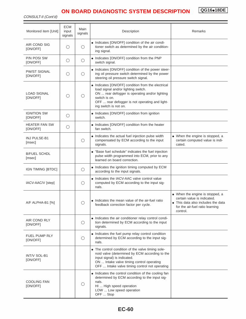
Monitored item [Unit]ECMinput
signals
Mainsignals
Description Remarks
AIR COND SIG[ON/OFF]
q qI Indicates [ON/OFF] condition of the air condi-
tioner switch as determined by the air condition-ing signal.
P/N POSI SW[ON/OFF]
q q I Indicates [ON/OFF] condition from the PNPswitch signal.
PW/ST SIGNAL[ON/OFF]
q qI Indicates [ON/OFF] condition of the power steer-
ing oil pressure switch determined by the powersteering oil pressure switch signal.
LOAD SIGNAL[ON/OFF]
q q
I Indicates [ON/OFF] condition from the electricalload signal and/or lighting switch.ON ... rear defogger is operating and/or lightingswitch is on.OFF ... rear defogger is not operating and light-ing switch is not on.
IGNITION SW[ON/OFF]
q I Indicates [ON/OFF] condition from ignitionswitch.
HEATER FAN SW[ON/OFF]
q I Indicates [ON/OFF] condition from the heaterfan switch.
INJ PULSE-B1[msec]
qI Indicates the actual fuel injection pulse width
compensated by ECM according to the inputsignals.
I When the engine is stopped, acertain computed value is indi-cated.
B/FUEL SCHDL[msec]
I “Base fuel schedule” indicates the fuel injectionpulse width programmed into ECM, prior to anylearned on board correction.
IGN TIMING [BTDC] q I Indicates the ignition timing computed by ECMaccording to the input signals.
IACV-AAC/V [step] qI Indicates the IACV-AAC valve control value
computed by ECM according to the input sig-nals.
A/F ALPHA-B1 [%] q I Indicates the mean value of the air-fuel ratiofeedback correction factor per cycle.
I When the engine is stopped, acertain value is indicated.
I This data also includes the datafor the air-fuel ratio learningcontrol.
AIR COND RLY[ON/OFF]
qI Indicates the air conditioner relay control condi-
tion determined by ECM according to the inputsignals.
FUEL PUMP RLY[ON/OFF]
qI Indicates the fuel pump relay control condition
determined by ECM according to the input sig-nals.
INT/V SOL-B1[ON/OFF]
I The control condition of the valve timing sole-noid valve (determined by ECM according to theinput signal) is indicated.ON ... Intake valve timing control operatingOFF ... Intake valve timing control not operating
COOLING FAN[ON/OFF]
q
I Indicates the control condition of the cooling fandetermined by ECM according to the input sig-nals.HI ... High speed operationLOW ... Low speed operationOFF ... Stop
ON BOARD DIAGNOSTIC SYSTEM DESCRIPTION QG16I18DECONSULT-II (Cont’d)
EC-60
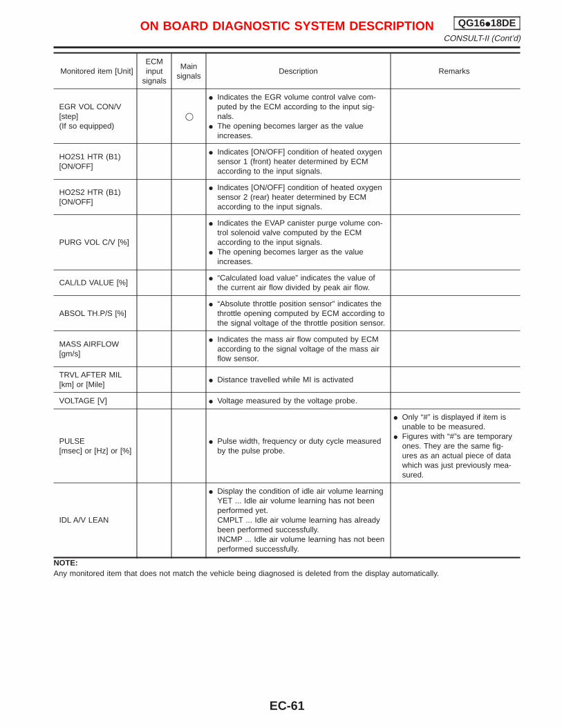
Monitored item [Unit]ECMinput
signals
Mainsignals
Description Remarks
EGR VOL CON/V[step](If so equipped)
q
I Indicates the EGR volume control valve com-puted by the ECM according to the input sig-nals.
I The opening becomes larger as the valueincreases.
HO2S1 HTR (B1)[ON/OFF]
I Indicates [ON/OFF] condition of heated oxygensensor 1 (front) heater determined by ECMaccording to the input signals.
HO2S2 HTR (B1)[ON/OFF]
I Indicates [ON/OFF] condition of heated oxygensensor 2 (rear) heater determined by ECMaccording to the input signals.
PURG VOL C/V [%]
I Indicates the EVAP canister purge volume con-trol solenoid valve computed by the ECMaccording to the input signals.
I The opening becomes larger as the valueincreases.
CAL/LD VALUE [%]I “Calculated load value” indicates the value of
the current air flow divided by peak air flow.
ABSOL TH.P/S [%]I “Absolute throttle position sensor” indicates the
throttle opening computed by ECM according tothe signal voltage of the throttle position sensor.
MASS AIRFLOW[gm/s]
I Indicates the mass air flow computed by ECMaccording to the signal voltage of the mass airflow sensor.
TRVL AFTER MIL[km] or [Mile]
I Distance travelled while MI is activated
VOLTAGE [V] I Voltage measured by the voltage probe.
PULSE[msec] or [Hz] or [%]
I Pulse width, frequency or duty cycle measuredby the pulse probe.
I Only “#” is displayed if item isunable to be measured.
I Figures with “#”s are temporaryones. They are the same fig-ures as an actual piece of datawhich was just previously mea-sured.
IDL A/V LEAN
I Display the condition of idle air volume learningYET ... Idle air volume learning has not beenperformed yet.CMPLT ... Idle air volume learning has alreadybeen performed successfully.INCMP ... Idle air volume learning has not beenperformed successfully.
NOTE:Any monitored item that does not match the vehicle being diagnosed is deleted from the display automatically.
ON BOARD DIAGNOSTIC SYSTEM DESCRIPTION QG16I18DECONSULT-II (Cont’d)
EC-61
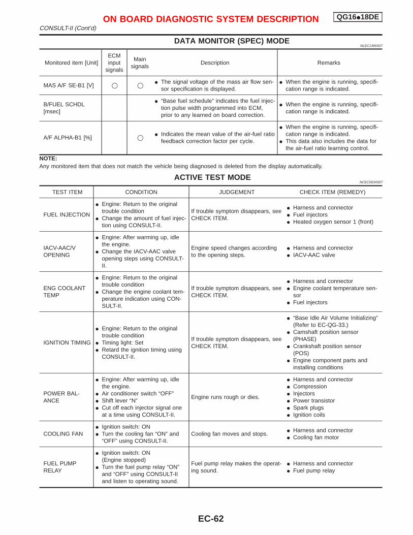
DATA MONITOR (SPEC) MODENLEC1365S07
Monitored item [Unit]ECMinput
signals
Mainsignals
Description Remarks
MAS A/F SE-B1 [V] q q I The signal voltage of the mass air flow sen-sor specification is displayed.
I When the engine is running, specifi-cation range is indicated.
B/FUEL SCHDL[msec]
I “Base fuel schedule” indicates the fuel injec-tion pulse width programmed into ECM,prior to any learned on board correction.
I When the engine is running, specifi-cation range is indicated.
A/F ALPHA-B1 [%] q I Indicates the mean value of the air-fuel ratiofeedback correction factor per cycle.
I When the engine is running, specifi-cation range is indicated.
I This data also includes the data forthe air-fuel ratio learning control.
NOTE:Any monitored item that does not match the vehicle being diagnosed is deleted from the display automatically.
ACTIVE TEST MODENCEC0034S07
TEST ITEM CONDITION JUDGEMENT CHECK ITEM (REMEDY)
FUEL INJECTION
I Engine: Return to the originaltrouble condition
I Change the amount of fuel injec-tion using CONSULT-II.
If trouble symptom disappears, seeCHECK ITEM.
I Harness and connectorI Fuel injectorsI Heated oxygen sensor 1 (front)
IACV-AAC/VOPENING
I Engine: After warming up, idlethe engine.
I Change the IACV-AAC valveopening steps using CONSULT-II.
Engine speed changes accordingto the opening steps.
I Harness and connectorI IACV-AAC valve
ENG COOLANTTEMP
I Engine: Return to the originaltrouble condition
I Change the engine coolant tem-perature indication using CON-SULT-II.
If trouble symptom disappears, seeCHECK ITEM.
I Harness and connectorI Engine coolant temperature sen-
sorI Fuel injectors
IGNITION TIMING
I Engine: Return to the originaltrouble condition
I Timing light: SetI Retard the ignition timing using
CONSULT-II.
If trouble symptom disappears, seeCHECK ITEM.
I “Base Idle Air Volume Initializing”(Refer to EC-QG-33.)
I Camshaft position sensor(PHASE)
I Crankshaft position sensor(POS)
I Engine component parts andinstalling conditions
POWER BAL-ANCE
I Engine: After warming up, idlethe engine.
I Air conditioner switch “OFF”I Shift lever “N”I Cut off each injector signal one
at a time using CONSULT-II.
Engine runs rough or dies.
I Harness and connectorI CompressionI InjectorsI Power transistorI Spark plugsI Ignition coils
COOLING FANI Ignition switch: ONI Turn the cooling fan “ON” and
“OFF” using CONSULT-II.Cooling fan moves and stops.
I Harness and connectorI Cooling fan motor
FUEL PUMPRELAY
I Ignition switch: ON(Engine stopped)
I Turn the fuel pump relay “ON”and “OFF” using CONSULT-IIand listen to operating sound.
Fuel pump relay makes the operat-ing sound.
I Harness and connectorI Fuel pump relay
ON BOARD DIAGNOSTIC SYSTEM DESCRIPTION QG16I18DECONSULT-II (Cont’d)
EC-62
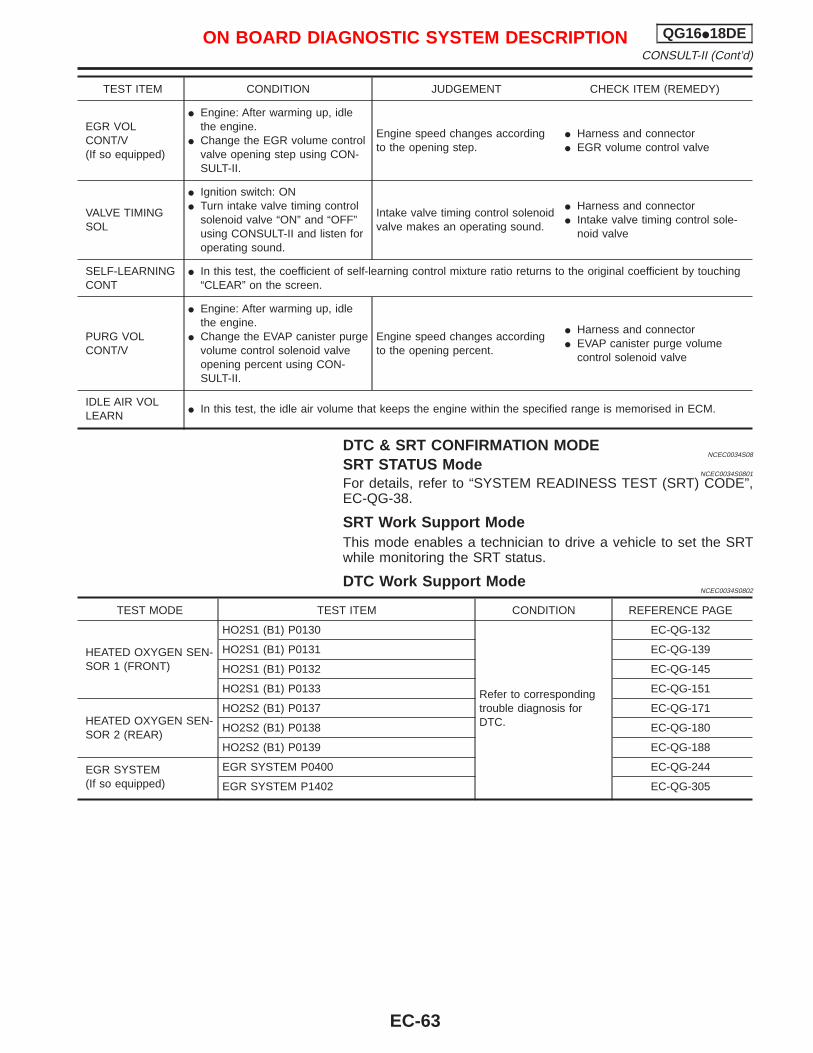
TEST ITEM CONDITION JUDGEMENT CHECK ITEM (REMEDY)
EGR VOLCONT/V(If so equipped)
I Engine: After warming up, idlethe engine.
I Change the EGR volume controlvalve opening step using CON-SULT-II.
Engine speed changes accordingto the opening step.
I Harness and connectorI EGR volume control valve
VALVE TIMINGSOL
I Ignition switch: ONI Turn intake valve timing control
solenoid valve “ON” and “OFF”using CONSULT-II and listen foroperating sound.
Intake valve timing control solenoidvalve makes an operating sound.
I Harness and connectorI Intake valve timing control sole-
noid valve
SELF-LEARNINGCONT
I In this test, the coefficient of self-learning control mixture ratio returns to the original coefficient by touching“CLEAR” on the screen.
PURG VOLCONT/V
I Engine: After warming up, idlethe engine.
I Change the EVAP canister purgevolume control solenoid valveopening percent using CON-SULT-II.
Engine speed changes accordingto the opening percent.
I Harness and connectorI EVAP canister purge volume
control solenoid valve
IDLE AIR VOLLEARN
I In this test, the idle air volume that keeps the engine within the specified range is memorised in ECM.
DTC & SRT CONFIRMATION MODENCEC0034S08
SRT STATUS ModeNCEC0034S0801
For details, refer to “SYSTEM READINESS TEST (SRT) CODE”,EC-QG-38.
SRT Work Support ModeThis mode enables a technician to drive a vehicle to set the SRTwhile monitoring the SRT status.
DTC Work Support ModeNCEC0034S0802
TEST MODE TEST ITEM CONDITION REFERENCE PAGE
HEATED OXYGEN SEN-SOR 1 (FRONT)
HO2S1 (B1) P0130
Refer to correspondingtrouble diagnosis forDTC.
EC-QG-132
HO2S1 (B1) P0131 EC-QG-139
HO2S1 (B1) P0132 EC-QG-145
HO2S1 (B1) P0133 EC-QG-151
HEATED OXYGEN SEN-SOR 2 (REAR)
HO2S2 (B1) P0137 EC-QG-171
HO2S2 (B1) P0138 EC-QG-180
HO2S2 (B1) P0139 EC-QG-188
EGR SYSTEM(If so equipped)
EGR SYSTEM P0400 EC-QG-244
EGR SYSTEM P1402 EC-QG-305
ON BOARD DIAGNOSTIC SYSTEM DESCRIPTION QG16I18DECONSULT-II (Cont’d)
EC-63
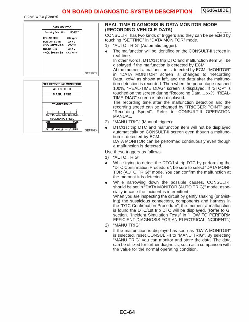
REAL TIME DIAGNOSIS IN DATA MONITOR MODE(RECORDING VEHICLE DATA)
NCEC0034S10
CONSULT-II has two kinds of triggers and they can be selected bytouching “SETTING” in “DATA MONITOR” mode.1) “AUTO TRIG” (Automatic trigger):I The malfunction will be identified on the CONSULT-II screen in
real time.In other words, DTC/1st trip DTC and malfunction item will bedisplayed if the malfunction is detected by ECM.At the moment a malfunction is detected by ECM, “MONITOR”in “DATA MONITOR” screen is changed to “RecordingData...xx%” as shown at left, and the data after the malfunc-tion detection is recorded. Then when the percentage reached100%, “REAL-TIME DIAG” screen is displayed. If ‘STOP” istouched on the screen during “Recording Data ... xx%, “REAL-TIME DIAG” screen is also displayed.The recording time after the malfunction detection and therecording speed can be changed by “TRIGGER POINT” and“Recording Speed”. Refer to CONSULT-II OPERATIONMANUAL.
2) “MANU TRIG” (Manual trigger):I DTC/1st trip DTC and malfunction item will not be displayed
automatically on CONSULT-II screen even though a malfunc-tion is detected by ECM.DATA MONITOR can be performed continuously even thougha malfunction is detected.
Use these triggers as follows:1) “AUTO TRIG”I While trying to detect the DTC/1st trip DTC by performing the
“DTC Confirmation Procedure”, be sure to select “DATA MONI-TOR (AUTO TRIG)” mode. You can confirm the malfunction atthe moment it is detected.
I While narrowing down the possible causes, CONSULT-IIshould be set in “DATA MONITOR (AUTO TRIG)” mode, espe-cially in case the incident is intermittent.When you are inspecting the circuit by gently shaking (or twist-ing) the suspicious connectors, components and harness inthe “DTC Confirmation Procedure”, the moment a malfunctionis found the DTC/1st trip DTC will be displayed. (Refer to GIsection, “Incident Simulation Tests” in “HOW TO PERFORMEFFICIENT DIAGNOSIS FOR AN ELECTRICAL INCIDENT”.)
2) “MANU TRIG”I If the malfunction is displayed as soon as “DATA MONITOR”
is selected, reset CONSULT-II to “MANU TRIG”. By selecting“MANU TRIG” you can monitor and store the data. The datacan be utilized for further diagnosis, such as a comparison withthe value for the normal operating condition.
SEF705Y
SEF707X
ON BOARD DIAGNOSTIC SYSTEM DESCRIPTION QG16I18DECONSULT-II (Cont’d)
EC-64
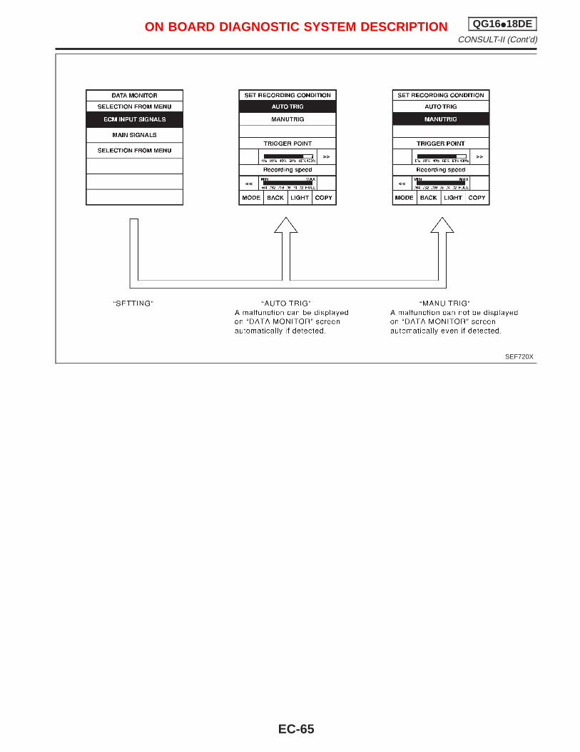
SEF720X
ON BOARD DIAGNOSTIC SYSTEM DESCRIPTION QG16I18DECONSULT-II (Cont’d)
EC-65
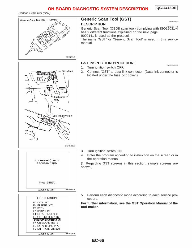
Generic Scan Tool (GST)=NCEC0035
DESCRIPTIONNCEC0035S01
Generic Scan Tool (OBDII scan tool) complying with ISO15031-4has 9 different functions explained on the next page.ISO9141 is used as the protocol.The name “GST” or “Generic Scan Tool” is used in this servicemanual.
GST INSPECTION PROCEDURENCEC0035S02
1. Turn ignition switch OFF.2. Connect “GST” to data link connector. (Data link connector is
located under the fuse box cover.)
3. Turn ignition switch ON.4. Enter the program according to instruction on the screen or in
the operation manual.(*: Regarding GST screens in this section, sample screens areshown.)
5. Perform each diagnostic mode according to each service pro-cedure.
For further information, see the GST Operation Manual of thetool maker.
SEF139P
SEF922W
SEF398S
SEF416S
ON BOARD DIAGNOSTIC SYSTEM DESCRIPTION QG16I18DEGeneric Scan Tool (GST)
EC-66
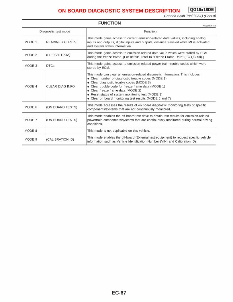
FUNCTIONNCEC0035S03
Diagnostic test mode Function
MODE 1 READINESS TESTSThis mode gains access to current emission-related data values, including analoginputs and outputs, digital inputs and outputs, distance traveled while MI is activatedand system status information.
MODE 2 (FREEZE DATA)This mode gains access to emission-related data value which were stored by ECMduring the freeze frame. [For details, refer to “Freeze Frame Data” (EC-QG-58).]
MODE 3 DTCsThis mode gains access to emission-related power train trouble codes which werestored by ECM.
MODE 4 CLEAR DIAG INFO
This mode can clear all emission-related diagnostic information. This includes:I Clear number of diagnostic trouble codes (MODE 1)I Clear diagnostic trouble codes (MODE 3)I Clear trouble code for freeze frame data (MODE 1)I Clear freeze frame data (MODE 2)I Reset status of system monitoring test (MODE 1)I Clear on board monitoring test results (MODE 6 and 7)
MODE 6 (ON BOARD TESTS)This mode accesses the results of on board diagnostic monitoring tests of specificcomponents/systems that are not continuously monitored.
MODE 7 (ON BOARD TESTS)This mode enables the off board test drive to obtain test results for emission-relatedpowertrain components/systems that are continuously monitored during normal drivingconditions.
MODE 8 — This mode is not applicable on this vehicle.
MODE 9 (CALIBRATION ID)This mode enables the off-board (External test equipment) to request specific vehicleinformation such as Vehicle Identification Number (VIN) and Calibration IDs.
ON BOARD DIAGNOSTIC SYSTEM DESCRIPTION QG16I18DEGeneric Scan Tool (GST) (Cont’d)
EC-67
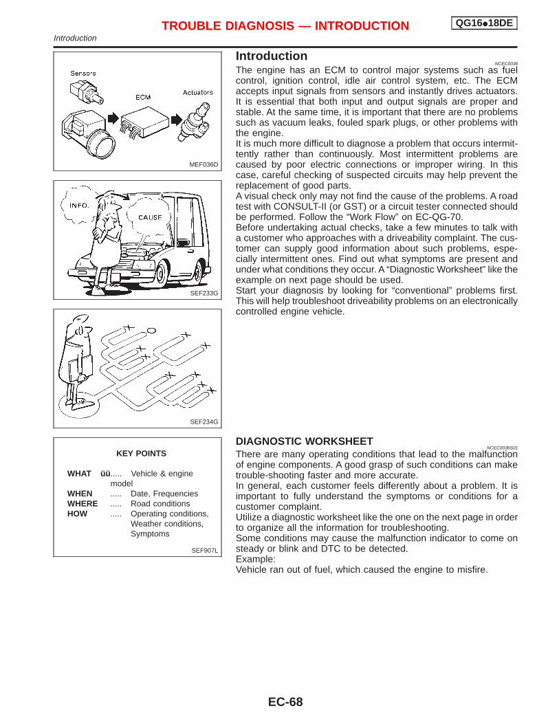
IntroductionNCEC0036
The engine has an ECM to control major systems such as fuelcontrol, ignition control, idle air control system, etc. The ECMaccepts input signals from sensors and instantly drives actuators.It is essential that both input and output signals are proper andstable. At the same time, it is important that there are no problemssuch as vacuum leaks, fouled spark plugs, or other problems withthe engine.It is much more difficult to diagnose a problem that occurs intermit-tently rather than continuously. Most intermittent problems arecaused by poor electric connections or improper wiring. In thiscase, careful checking of suspected circuits may help prevent thereplacement of good parts.A visual check only may not find the cause of the problems. A roadtest with CONSULT-II (or GST) or a circuit tester connected shouldbe performed. Follow the “Work Flow” on EC-QG-70.Before undertaking actual checks, take a few minutes to talk witha customer who approaches with a driveability complaint. The cus-tomer can supply good information about such problems, espe-cially intermittent ones. Find out what symptoms are present andunder what conditions they occur. A “Diagnostic Worksheet” like theexample on next page should be used.Start your diagnosis by looking for “conventional” problems first.This will help troubleshoot driveability problems on an electronicallycontrolled engine vehicle.
DIAGNOSTIC WORKSHEETNCEC0036S01
There are many operating conditions that lead to the malfunctionof engine components. A good grasp of such conditions can maketrouble-shooting faster and more accurate.In general, each customer feels differently about a problem. It isimportant to fully understand the symptoms or conditions for acustomer complaint.Utilize a diagnostic worksheet like the one on the next page in orderto organize all the information for troubleshooting.Some conditions may cause the malfunction indicator to come onsteady or blink and DTC to be detected.Example:Vehicle ran out of fuel, which caused the engine to misfire.
MEF036D
SEF233G
SEF234G
SEF907L
KEY POINTS
WHAT üü ..... Vehicle & enginemodel
WHEN ..... Date, FrequenciesWHERE ..... Road conditionsHOW ..... Operating conditions,
Weather conditions,Symptoms
TROUBLE DIAGNOSIS — INTRODUCTION QG16I18DEIntroduction
EC-68
Worksheet SampleNCEC0036S0101
MTBL0311
TROUBLE DIAGNOSIS — INTRODUCTION QG16I18DEIntroduction (Cont’d)
EC-69
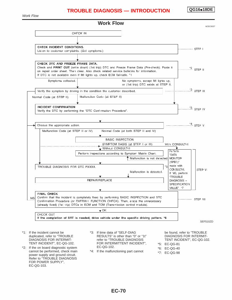
Work FlowNCEC0037
*1: If the incident cannot beduplicated, refer to “TROUBLEDIAGNOSIS FOR INTERMIT-TENT INCIDENT”, EC-QG-102.
*2: If the on board diagnostic systemcannot be performed, check mainpower supply and ground circuit.Refer to “TROUBLE DIAGNOSISFOR POWER SUPPLY”,EC-QG-103.
*3: If time data of “SELF-DIAGRESULTS” is other than “0” or “1t”refer to “TROUBLE DIAGNOSISFOR INTERMITTENT INCIDENT”,EC-QG-102.
*4: If the malfunctioning part cannot
be found, refer to “TROUBLEDIAGNOSIS FOR INTERMIT-TENT INCIDENT”, EC-QG-102.
*5: EC-QG-81*6: EC-QG-40*7: EC-QG-98
SEF510ZD
TROUBLE DIAGNOSIS — INTRODUCTION QG16I18DEWork Flow
EC-70
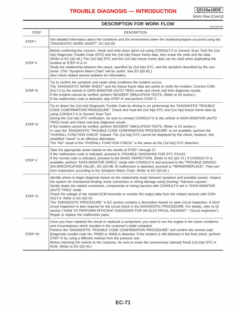
DESCRIPTION FOR WORK FLOWNCEC0037S01
STEP DESCRIPTION
STEP IGet detailed information about the conditions and the environment when the incident/symptom occurred using the“DIAGNOSTIC WORK SHEET”, EC-QG-69.
STEP II
Before confirming the concern, check and write down (print out using CONSULT-II or Generic Scan Tool) the (1sttrip) Diagnostic Trouble Code (DTC) and the (1st trip) freeze frame data, then erase the code and the data.(Refer to EC-QG-44.) The (1st trip) DTC and the (1st trip) freeze frame data can be used when duplicating theincident at STEP III & IV.Study the relationship between the cause, specified by (1st trip) DTC, and the symptom described by the cus-tomer. (The “Symptom Matrix Chart” will be useful. See EC-QG-82.)Also check related service bulletins for information.
STEP III
Try to confirm the symptom and under what conditions the incident occurs.The “DIAGNOSTIC WORK SHEET” and the freeze frame data are useful to verify the incident. Connect CON-SULT-II to the vehicle in DATA MONITOR (AUTO TRIG) mode and check real time diagnosis results.If the incident cannot be verified, perform INCIDENT SIMULATION TESTS. (Refer to GI section.)If the malfunction code is detected, skip STEP IV and perform STEP V.
STEP IV
Try to detect the (1st trip) Diagnostic Trouble Code by driving in (or performing) the “DIAGNOSTIC TROUBLECODE CONFIRMATION PROCEDURE”. Check and read the (1st trip) DTC and (1st trip) freeze frame data byusing CONSULT-II or Generic Scan Tool.During the (1st trip) DTC verification, be sure to connect CONSULT-II to the vehicle in DATA MONITOR (AUTOTRIG) mode and check real time diagnosis results.If the incident cannot be verified, perform INCIDENT SIMULATION TESTS. (Refer to GI section.)In case the “DIAGNOSTIC TROUBLE CODE CONFIRMATION PROCEDURE” is not available, perform the“OVERALL FUNCTION CHECK” instead. The (1st trip) DTC cannot be displayed by this check, however, thissimplified “check” is an effective alternative.The “NG” result of the “OVERALL FUNCTION CHECK” is the same as the (1st trip) DTC detection.
STEP V
Take the appropriate action based on the results of STEP I through IV.If the malfunction code is indicated, proceed to TROUBLE DIAGNOSIS FOR DTC PXXXX.If the normal code is indicated, proceed to the BASIC INSPECTION. (Refer to EC-QG-72.) If CONSULT-II isavailable, perform “DATA MONITOR (SPEC)” mode with CONSULT-II and proceed to the “TROUBLE DIAGNO-SIS-SPECIFICATION VALUE”, EC-QG-98. (If malfunction is detected, proceed to “REPAIR/REPLACE”. Then per-form inspections according to the Symptom Matrix Chart. (Refer to EC-QG-82.)
STEP VI
Identify where to begin diagnosis based on the relationship study between symptom and possible causes. Inspectthe system for mechanical binding, loose connectors or wiring damage using (tracing) “Harness Layouts”.Gently shake the related connectors, components or wiring harness with CONSULT-II set in “DATA MONITOR(AUTO TRIG)” mode.Check the voltage of the related ECM terminals or monitor the output data from the related sensors with CON-SULT-II. Refer to EC-QG-91.The “DIAGNOSTIC PROCEDURE” in EC section contains a description based on open circuit inspection. A shortcircuit inspection is also required for the circuit check in the DIAGNOSTIC PROCEDURE. For details, refer to GIsection (“HOW TO PERFORM EFFICIENT DIAGNOSIS FOR AN ELECTRICAL INCIDENT”, “Circuit Inspection”).Repair or replace the malfunction parts.
STEP VII
Once you have repaired the circuit or replaced a component, you need to run the engine in the same conditionsand circumstances which resulted in the customer’s initial complaint.Perform the “DIAGNOSTIC TROUBLE CODE CONFIRMATION PROCEDURE” and confirm the normal code[Diagnostic trouble code No. P0000 or 0000] is detected. If the incident is still detected in the final check, performSTEP VI by using a different method from the previous one.Before returning the vehicle to the customer, be sure to erase the unnecessary (already fixed) (1st trip) DTC inECM. (Refer to EC-QG-44.)
TROUBLE DIAGNOSIS — INTRODUCTION QG16I18DEWork Flow (Cont’d)
EC-71
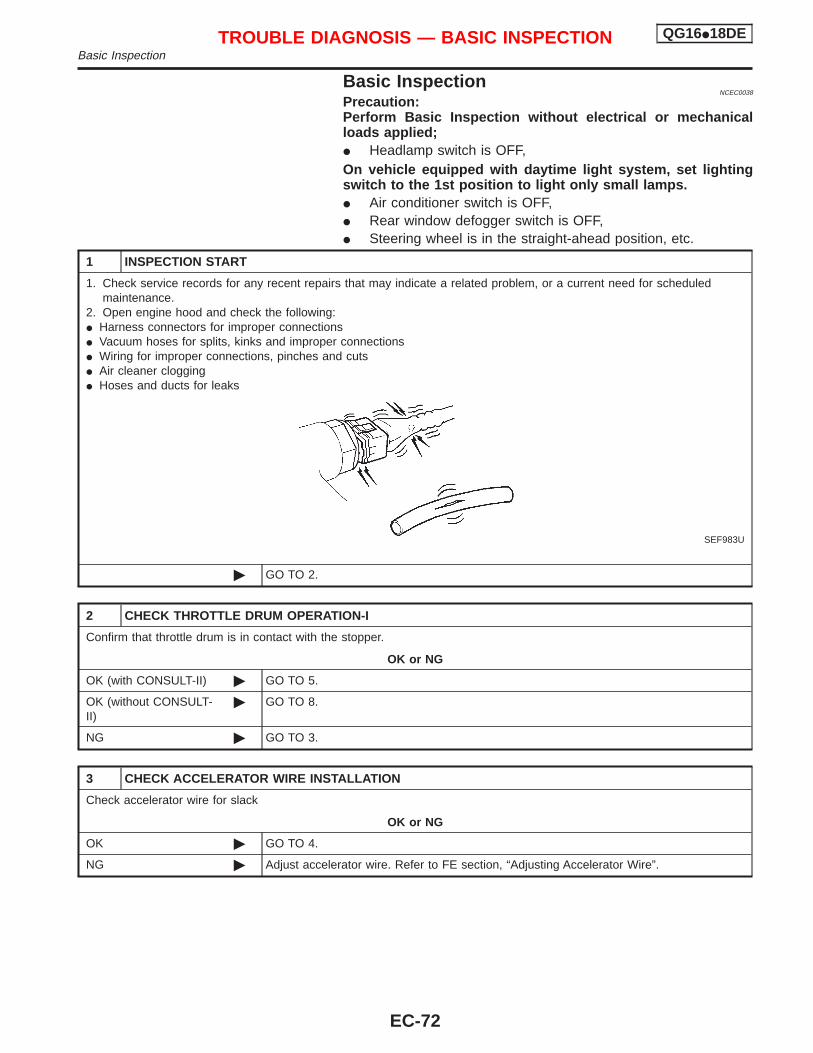
Basic InspectionNCEC0038
Precaution:Perform Basic Inspection without electrical or mechanicalloads applied;I Headlamp switch is OFF,On vehicle equipped with daytime light system, set lightingswitch to the 1st position to light only small lamps.I Air conditioner switch is OFF,I Rear window defogger switch is OFF,I Steering wheel is in the straight-ahead position, etc.
1 INSPECTION START
1. Check service records for any recent repairs that may indicate a related problem, or a current need for scheduledmaintenance.
2. Open engine hood and check the following:I Harness connectors for improper connectionsI Vacuum hoses for splits, kinks and improper connectionsI Wiring for improper connections, pinches and cutsI Air cleaner cloggingI Hoses and ducts for leaks
SEF983U
© GO TO 2.
2 CHECK THROTTLE DRUM OPERATION-I
Confirm that throttle drum is in contact with the stopper.
OK or NG
OK (with CONSULT-II) © GO TO 5.
OK (without CONSULT-II)
© GO TO 8.
NG © GO TO 3.
3 CHECK ACCELERATOR WIRE INSTALLATION
Check accelerator wire for slack
OK or NG
OK © GO TO 4.
NG © Adjust accelerator wire. Refer to FE section, “Adjusting Accelerator Wire”.
TROUBLE DIAGNOSIS — BASIC INSPECTION QG16I18DEBasic Inspection
EC-72
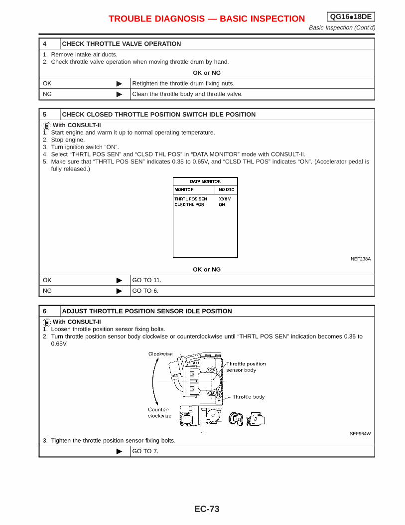
4 CHECK THROTTLE VALVE OPERATION
1. Remove intake air ducts.2. Check throttle valve operation when moving throttle drum by hand.
OK or NG
OK © Retighten the throttle drum fixing nuts.
NG © Clean the throttle body and throttle valve.
5 CHECK CLOSED THROTTLE POSITION SWITCH IDLE POSITION
With CONSULT-II1. Start engine and warm it up to normal operating temperature.2. Stop engine.3. Turn ignition switch “ON”.4. Select “THRTL POS SEN” and “CLSD THL POS” in “DATA MONITOR” mode with CONSULT-II.5. Make sure that “THRTL POS SEN” indicates 0.35 to 0.65V, and “CLSD THL POS” indicates “ON”. (Accelerator pedal is
fully released.)
NEF238A
OK or NG
OK © GO TO 11.
NG © GO TO 6.
6 ADJUST THROTTLE POSITION SENSOR IDLE POSITION
With CONSULT-II1. Loosen throttle position sensor fixing bolts.2. Turn throttle position sensor body clockwise or counterclockwise until “THRTL POS SEN” indication becomes 0.35 to
0.65V.
SEF964W
3. Tighten the throttle position sensor fixing bolts.
© GO TO 7.
TROUBLE DIAGNOSIS — BASIC INSPECTION QG16I18DEBasic Inspection (Cont’d)
EC-73
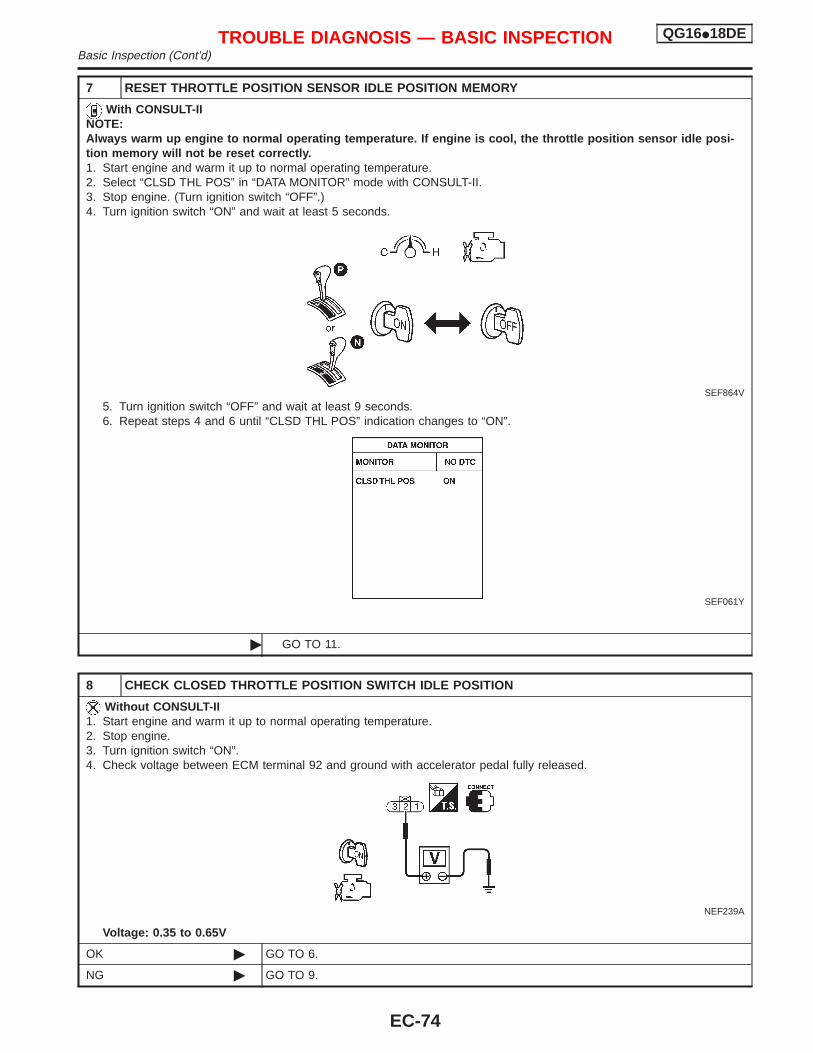
7 RESET THROTTLE POSITION SENSOR IDLE POSITION MEMORY
With CONSULT-IINOTE:Always warm up engine to normal operating temperature. If engine is cool, the throttle position sensor idle posi-tion memory will not be reset correctly.1. Start engine and warm it up to normal operating temperature.2. Select “CLSD THL POS” in “DATA MONITOR” mode with CONSULT-II.3. Stop engine. (Turn ignition switch “OFF”.)4. Turn ignition switch “ON” and wait at least 5 seconds.
SEF864V
5. Turn ignition switch “OFF” and wait at least 9 seconds.6. Repeat steps 4 and 6 until “CLSD THL POS” indication changes to “ON”.
SEF061Y
© GO TO 11.
8 CHECK CLOSED THROTTLE POSITION SWITCH IDLE POSITION
Without CONSULT-II1. Start engine and warm it up to normal operating temperature.2. Stop engine.3. Turn ignition switch “ON”.4. Check voltage between ECM terminal 92 and ground with accelerator pedal fully released.
NEF239A
Voltage: 0.35 to 0.65V
OK © GO TO 6.
NG © GO TO 9.
TROUBLE DIAGNOSIS — BASIC INSPECTION QG16I18DEBasic Inspection (Cont’d)
EC-74
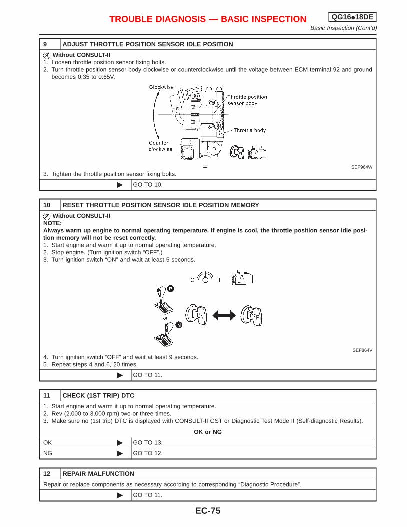
9 ADJUST THROTTLE POSITION SENSOR IDLE POSITION
Without CONSULT-II1. Loosen throttle position sensor fixing bolts.2. Turn throttle position sensor body clockwise or counterclockwise until the voltage between ECM terminal 92 and ground
becomes 0.35 to 0.65V.
SEF964W
3. Tighten the throttle position sensor fixing bolts.
© GO TO 10.
10 RESET THROTTLE POSITION SENSOR IDLE POSITION MEMORY
Without CONSULT-IINOTE:Always warm up engine to normal operating temperature. If engine is cool, the throttle position sensor idle posi-tion memory will not be reset correctly.1. Start engine and warm it up to normal operating temperature.2. Stop engine. (Turn ignition switch “OFF”.)3. Turn ignition switch “ON” and wait at least 5 seconds.
SEF864V
4. Turn ignition switch “OFF” and wait at least 9 seconds.5. Repeat steps 4 and 6, 20 times.
© GO TO 11.
11 CHECK (1ST TRIP) DTC
1. Start engine and warm it up to normal operating temperature.2. Rev (2,000 to 3,000 rpm) two or three times.3. Make sure no (1st trip) DTC is displayed with CONSULT-II GST or Diagnostic Test Mode II (Self-diagnostic Results).
OK or NG
OK © GO TO 13.
NG © GO TO 12.
12 REPAIR MALFUNCTION
Repair or replace components as necessary according to corresponding “Diagnostic Procedure”.
© GO TO 11.
TROUBLE DIAGNOSIS — BASIC INSPECTION QG16I18DEBasic Inspection (Cont’d)
EC-75
13 CHECK TARGET IDLE SPEED
With CONSULT-II1. Start engine and warm it up to normal operating temperature.2. Select “ENG SPEED” in “DATA MONITOR” mode With CONSULT-II.3. Check idle speed.
700±50 rpm
Without CONSULT-II1. Start engine and warm it up to normal operating temperature.2. Check idle speed.
700±50 rpm
OK or NG
OK © GO TO 22.
NG © GO TO 14.
14 PERFORM IDLE AIR VOLUME LEARNING
Refer to “Idle Air Volume Learning”, EC-QG-33.Which is the result CMPLT or INCMP?
CMPLT or INCMP
CMPLT © GO TO 15.
INCMP © 1. Follow the instruction of “Idle Air Volume Learning”.2. GO TO 14.
15 CHECK TARGET IDLE SPEED AGAIN
With CONSULT-II1. Start engine and warm it up to normal operating temperature.2. Select “ENG SPEED” in “DATA MONITOR” mode With CONSULT-II.3. Check idle speed.
700±50 rpm
Without CONSULT-II1. Start engine and warm it up to normal operating temperature.2. Check idle speed.
700±50 rpm
OK or NG
OK © GO TO 20.
NG © GO TO 16.
16 REPLACE IACV-AAC VALVE
Replace IACV-AAC valve.
© GO TO 17.
17 PERFORM IDLE AIR VOLUME LEARNING
Refer to “Idle Air Volume Learning”, EC-QG-33.Which is the result CMPLT or INCMP?
CMPLT or INCMP
CMPLT © GO TO 18.
INCMP © 1. Follow the instruction of “Idle Air Volume Learning”.2. GO TO 14.
TROUBLE DIAGNOSIS — BASIC INSPECTION QG16I18DEBasic Inspection (Cont’d)
EC-76
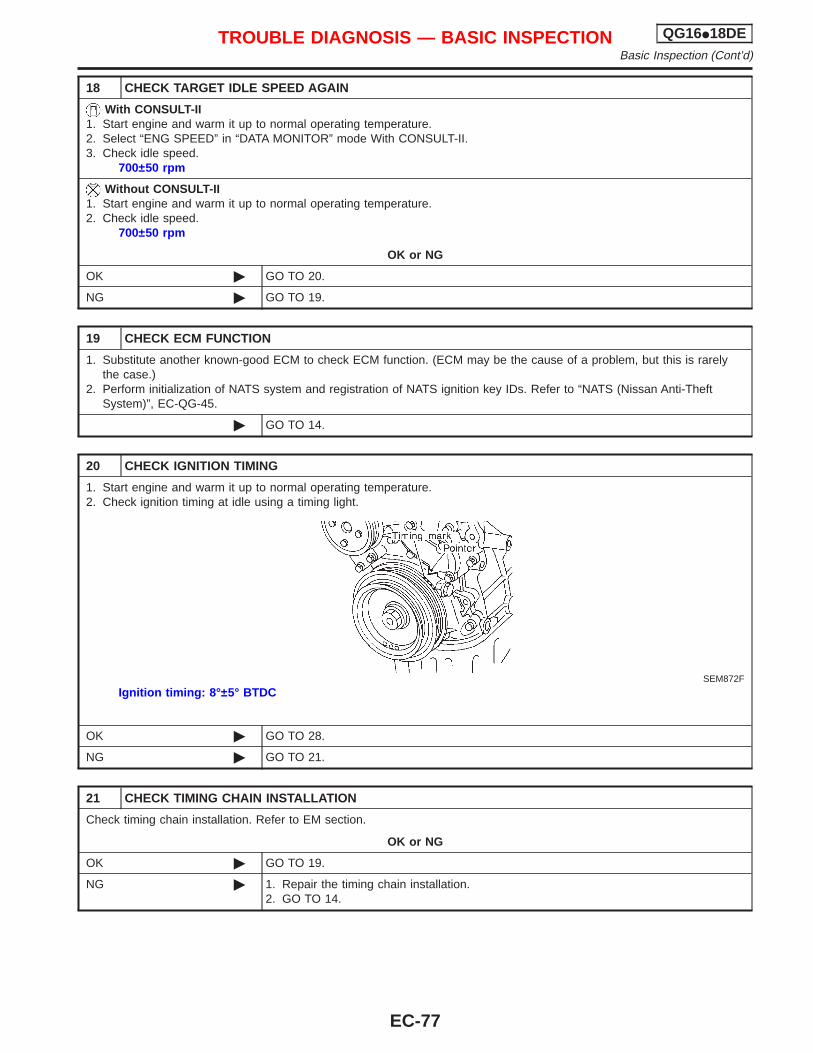
18 CHECK TARGET IDLE SPEED AGAIN
With CONSULT-II1. Start engine and warm it up to normal operating temperature.2. Select “ENG SPEED” in “DATA MONITOR” mode With CONSULT-II.3. Check idle speed.
700±50 rpm
Without CONSULT-II1. Start engine and warm it up to normal operating temperature.2. Check idle speed.
700±50 rpm
OK or NG
OK © GO TO 20.
NG © GO TO 19.
19 CHECK ECM FUNCTION
1. Substitute another known-good ECM to check ECM function. (ECM may be the cause of a problem, but this is rarelythe case.)
2. Perform initialization of NATS system and registration of NATS ignition key IDs. Refer to “NATS (Nissan Anti-TheftSystem)”, EC-QG-45.
© GO TO 14.
20 CHECK IGNITION TIMING
1. Start engine and warm it up to normal operating temperature.2. Check ignition timing at idle using a timing light.
SEM872F
Ignition timing: 8°±5° BTDC
OK © GO TO 28.
NG © GO TO 21.
21 CHECK TIMING CHAIN INSTALLATION
Check timing chain installation. Refer to EM section.
OK or NG
OK © GO TO 19.
NG © 1. Repair the timing chain installation.2. GO TO 14.
TROUBLE DIAGNOSIS — BASIC INSPECTION QG16I18DEBasic Inspection (Cont’d)
EC-77
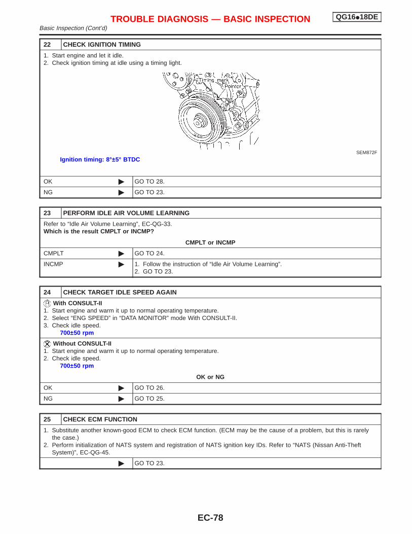
22 CHECK IGNITION TIMING
1. Start engine and let it idle.2. Check ignition timing at idle using a timing light.
SEM872F
Ignition timing: 8°±5° BTDC
OK © GO TO 28.
NG © GO TO 23.
23 PERFORM IDLE AIR VOLUME LEARNING
Refer to “Idle Air Volume Learning”, EC-QG-33.Which is the result CMPLT or INCMP?
CMPLT or INCMP
CMPLT © GO TO 24.
INCMP © 1. Follow the instruction of “Idle Air Volume Learning”.2. GO TO 23.
24 CHECK TARGET IDLE SPEED AGAIN
With CONSULT-II1. Start engine and warm it up to normal operating temperature.2. Select “ENG SPEED” in “DATA MONITOR” mode With CONSULT-II.3. Check idle speed.
700±50 rpm
Without CONSULT-II1. Start engine and warm it up to normal operating temperature.2. Check idle speed.
700±50 rpm
OK or NG
OK © GO TO 26.
NG © GO TO 25.
25 CHECK ECM FUNCTION
1. Substitute another known-good ECM to check ECM function. (ECM may be the cause of a problem, but this is rarelythe case.)
2. Perform initialization of NATS system and registration of NATS ignition key IDs. Refer to “NATS (Nissan Anti-TheftSystem)”, EC-QG-45.
© GO TO 23.
TROUBLE DIAGNOSIS — BASIC INSPECTION QG16I18DEBasic Inspection (Cont’d)
EC-78
26 CHECK IGNITION TIMING AGAIN
Check ignition timing again. Refer to Test No. 22.
OK © GO TO 28.
NG © GO TO 27.
27 CHECK TIMING CHAIN INSTALLATION
Check timing chain installation. Refer to EM section.
OK or NG
OK © GO TO 25.
NG © 1. Repair the timing chain installation.2. GO TO 23.
28 ERASE UNNECESSARY DTC
After this inspection, unnecessary DTC No. might be displayed.Erase the stored memory in ECM.Refer to “HOW TO ERASE EMISSION-RELATED DIAGNOSTIC INFORMATION”, EC-QG-44.
© INSPECTION END
TROUBLE DIAGNOSIS — BASIC INSPECTION QG16I18DEBasic Inspection (Cont’d)
EC-79
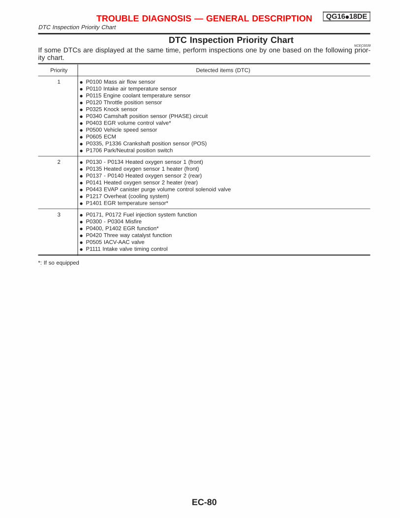
DTC Inspection Priority ChartNCEC0039
If some DTCs are displayed at the same time, perform inspections one by one based on the following prior-ity chart.
Priority Detected items (DTC)
1 I P0100 Mass air flow sensorI P0110 Intake air temperature sensorI P0115 Engine coolant temperature sensorI P0120 Throttle position sensorI P0325 Knock sensorI P0340 Camshaft position sensor (PHASE) circuitI P0403 EGR volume control valve*I P0500 Vehicle speed sensorI P0605 ECMI P0335, P1336 Crankshaft position sensor (POS)I P1706 Park/Neutral position switch
2 I P0130 - P0134 Heated oxygen sensor 1 (front)I P0135 Heated oxygen sensor 1 heater (front)I P0137 - P0140 Heated oxygen sensor 2 (rear)I P0141 Heated oxygen sensor 2 heater (rear)I P0443 EVAP canister purge volume control solenoid valveI P1217 Overheat (cooling system)I P1401 EGR temperature sensor*
3 I P0171, P0172 Fuel injection system functionI P0300 - P0304 MisfireI P0400, P1402 EGR function*I P0420 Three way catalyst functionI P0505 IACV-AAC valveI P1111 Intake valve timing control
*: If so equipped
TROUBLE DIAGNOSIS — GENERAL DESCRIPTION QG16I18DEDTC Inspection Priority Chart
EC-80
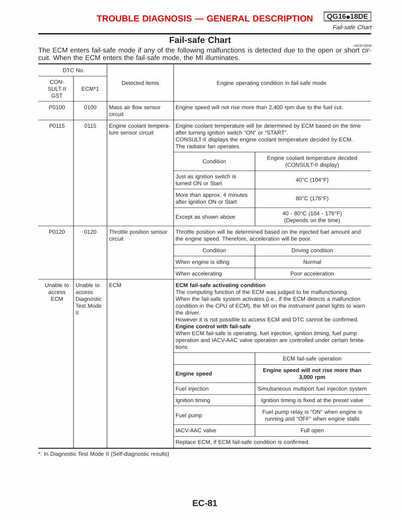
Fail-safe Chart=NCEC0040
The ECM enters fail-safe mode if any of the following malfunctions is detected due to the open or short cir-cuit. When the ECM enters the fail-safe mode, the MI illuminates.
DTC No.
Detected items Engine operating condition in fail-safe modeCON-SULT-II
GSTECM*1
P0100 0100 Mass air flow sensorcircuit
Engine speed will not rise more than 2,400 rpm due to the fuel cut.
P0115 0115 Engine coolant tempera-ture sensor circuit
Engine coolant temperature will be determined by ECM based on the timeafter turning ignition switch “ON” or “START”.CONSULT-II displays the engine coolant temperature decided by ECM.The radiator fan operates.
ConditionEngine coolant temperature decided
(CONSULT-II display)
Just as ignition switch isturned ON or Start
40°C (104°F)
More than approx. 4 minutesafter ignition ON or Start
80°C (176°F)
Except as shown above40 - 80°C (104 - 176°F)(Depends on the time)
P0120 0120 Throttle position sensorcircuit
Throttle position will be determined based on the injected fuel amount andthe engine speed. Therefore, acceleration will be poor.
Condition Driving condition
When engine is idling Normal
When accelerating Poor acceleration
Unable toaccessECM
Unable toaccessDiagnosticTest ModeII
ECM ECM fail-safe activating conditionThe computing function of the ECM was judged to be malfunctioning.When the fail-safe system activates (i.e., if the ECM detects a malfunctioncondition in the CPU of ECM), the MI on the instrument panel lights to warnthe driver.However it is not possible to access ECM and DTC cannot be confirmed.Engine control with fail-safeWhen ECM fail-safe is operating, fuel injection, ignition timing, fuel pumpoperation and IACV-AAC valve operation are controlled under certain limita-tions.
ECM fail-safe operation
Engine speedEngine speed will not rise more than
3,000 rpm
Fuel injection Simultaneous multiport fuel injection system
Ignition timing Ignition timing is fixed at the preset valve
Fuel pumpFuel pump relay is “ON” when engine isrunning and “OFF” when engine stalls
IACV-AAC valve Full open
Replace ECM, if ECM fail-safe condition is confirmed.
*: In Diagnostic Test Mode II (Self-diagnostic results)
TROUBLE DIAGNOSIS — GENERAL DESCRIPTION QG16I18DEFail-safe Chart
EC-81
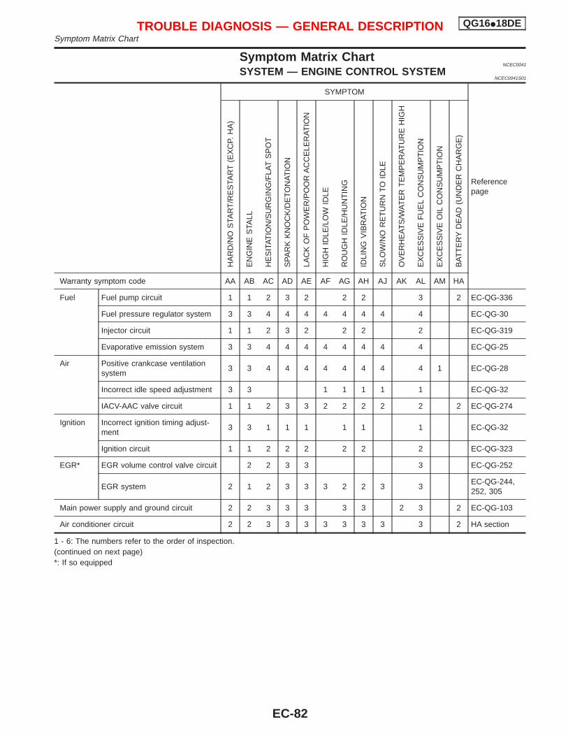
Symptom Matrix ChartNCEC0041
SYSTEM — ENGINE CONTROL SYSTEMNCEC0041S01
SYMPTOM
Referencepage
HA
RD
/NO
STA
RT
/RE
STA
RT
(EX
CP.
HA
)
EN
GIN
ES
TALL
HE
SIT
AT
ION
/SU
RG
ING
/FLA
TS
PO
T
SP
AR
KK
NO
CK
/DE
TO
NA
TIO
N
LAC
KO
FP
OW
ER
/PO
OR
AC
CE
LER
AT
ION
HIG
HID
LE/L
OW
IDLE
RO
UG
HID
LE/H
UN
TIN
G
IDLI
NG
VIB
RA
TIO
N
SLO
W/N
OR
ET
UR
NT
OID
LE
OV
ER
HE
AT
S/W
AT
ER
TE
MP
ER
AT
UR
EH
IGH
EX
CE
SS
IVE
FU
EL
CO
NS
UM
PT
ION
EX
CE
SS
IVE
OIL
CO
NS
UM
PT
ION
BA
TT
ER
YD
EA
D(U
ND
ER
CH
AR
GE
)
Warranty symptom code AA AB AC AD AE AF AG AH AJ AK AL AM HA
Fuel Fuel pump circuit 1 1 2 3 2 2 2 3 2 EC-QG-336
Fuel pressure regulator system 3 3 4 4 4 4 4 4 4 4 EC-QG-30
Injector circuit 1 1 2 3 2 2 2 2 EC-QG-319
Evaporative emission system 3 3 4 4 4 4 4 4 4 4 EC-QG-25
Air Positive crankcase ventilationsystem
3 3 4 4 4 4 4 4 4 4 1 EC-QG-28
Incorrect idle speed adjustment 3 3 1 1 1 1 1 EC-QG-32
IACV-AAC valve circuit 1 1 2 3 3 2 2 2 2 2 2 EC-QG-274
Ignition Incorrect ignition timing adjust-ment
3 3 1 1 1 1 1 1 EC-QG-32
Ignition circuit 1 1 2 2 2 2 2 2 EC-QG-323
EGR* EGR volume control valve circuit 2 2 3 3 3 EC-QG-252
EGR system 2 1 2 3 3 3 2 2 3 3EC-QG-244,252, 305
Main power supply and ground circuit 2 2 3 3 3 3 3 2 3 2 EC-QG-103
Air conditioner circuit 2 2 3 3 3 3 3 3 3 3 2 HA section
1 - 6: The numbers refer to the order of inspection.(continued on next page)*: If so equipped
TROUBLE DIAGNOSIS — GENERAL DESCRIPTION QG16I18DESymptom Matrix Chart
EC-82
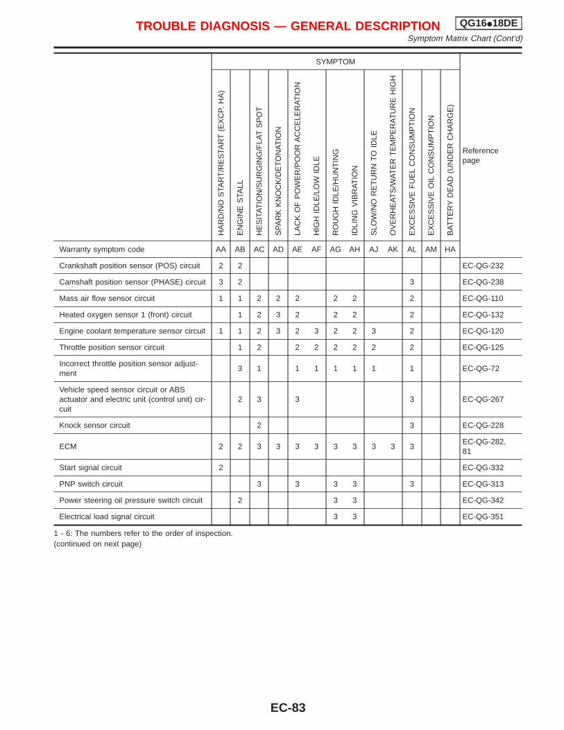
SYMPTOM
Referencepage
HA
RD
/NO
STA
RT
/RE
STA
RT
(EX
CP.
HA
)
EN
GIN
ES
TALL
HE
SIT
AT
ION
/SU
RG
ING
/FLA
TS
PO
T
SP
AR
KK
NO
CK
/DE
TO
NA
TIO
N
LAC
KO
FP
OW
ER
/PO
OR
AC
CE
LER
AT
ION
HIG
HID
LE/L
OW
IDLE
RO
UG
HID
LE/H
UN
TIN
G
IDLI
NG
VIB
RA
TIO
N
SLO
W/N
OR
ET
UR
NT
OID
LE
OV
ER
HE
AT
S/W
AT
ER
TE
MP
ER
AT
UR
EH
IGH
EX
CE
SS
IVE
FU
EL
CO
NS
UM
PT
ION
EX
CE
SS
IVE
OIL
CO
NS
UM
PT
ION
BA
TT
ER
YD
EA
D(U
ND
ER
CH
AR
GE
)
Warranty symptom code AA AB AC AD AE AF AG AH AJ AK AL AM HA
Crankshaft position sensor (POS) circuit 2 2 EC-QG-232
Camshaft position sensor (PHASE) circuit 3 2 3 EC-QG-238
Mass air flow sensor circuit 1 1 2 2 2 2 2 2 EC-QG-110
Heated oxygen sensor 1 (front) circuit 1 2 3 2 2 2 2 EC-QG-132
Engine coolant temperature sensor circuit 1 1 2 3 2 3 2 2 3 2 EC-QG-120
Throttle position sensor circuit 1 2 2 2 2 2 2 2 EC-QG-125
Incorrect throttle position sensor adjust-ment
3 1 1 1 1 1 1 1 EC-QG-72
Vehicle speed sensor circuit or ABSactuator and electric unit (control unit) cir-cuit
2 3 3 3 EC-QG-267
Knock sensor circuit 2 3 EC-QG-228
ECM 2 2 3 3 3 3 3 3 3 3 3EC-QG-282,81
Start signal circuit 2 EC-QG-332
PNP switch circuit 3 3 3 3 3 EC-QG-313
Power steering oil pressure switch circuit 2 3 3 EC-QG-342
Electrical load signal circuit 3 3 EC-QG-351
1 - 6: The numbers refer to the order of inspection.(continued on next page)
TROUBLE DIAGNOSIS — GENERAL DESCRIPTION QG16I18DESymptom Matrix Chart (Cont’d)
EC-83
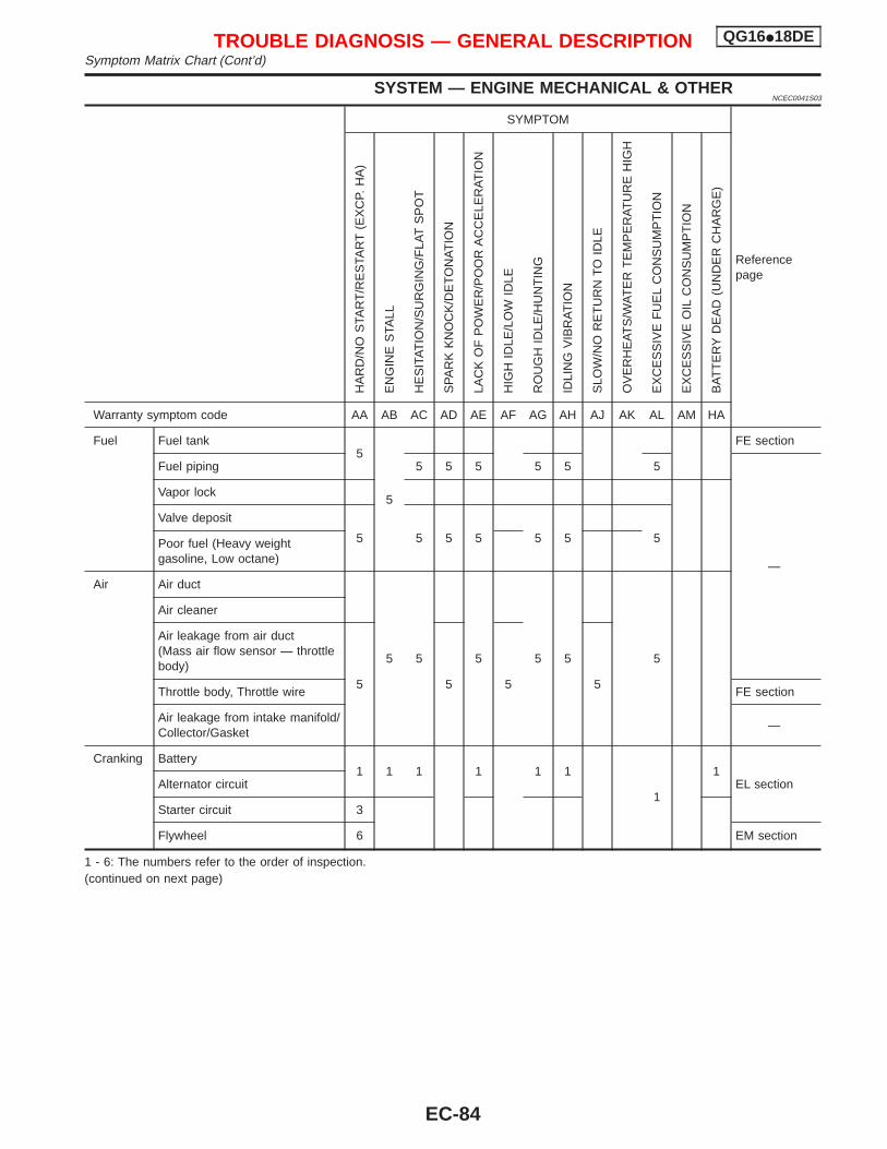
SYSTEM — ENGINE MECHANICAL & OTHERNCEC0041S03
SYMPTOM
Referencepage
HA
RD
/NO
STA
RT
/RE
STA
RT
(EX
CP.
HA
)
EN
GIN
ES
TALL
HE
SIT
AT
ION
/SU
RG
ING
/FLA
TS
PO
T
SP
AR
KK
NO
CK
/DE
TO
NA
TIO
N
LAC
KO
FP
OW
ER
/PO
OR
AC
CE
LER
AT
ION
HIG
HID
LE/L
OW
IDLE
RO
UG
HID
LE/H
UN
TIN
G
IDLI
NG
VIB
RA
TIO
N
SLO
W/N
OR
ET
UR
NT
OID
LE
OV
ER
HE
AT
S/W
AT
ER
TE
MP
ER
AT
UR
EH
IGH
EX
CE
SS
IVE
FU
EL
CO
NS
UM
PT
ION
EX
CE
SS
IVE
OIL
CO
NS
UM
PT
ION
BA
TT
ER
YD
EA
D(U
ND
ER
CH
AR
GE
)
Warranty symptom code AA AB AC AD AE AF AG AH AJ AK AL AM HA
Fuel Fuel tank5
5
FE section
Fuel piping 5 5 5 5 5 5
—
Vapor lock
Valve deposit
5 5 5 5 5 5 5Poor fuel (Heavy weightgasoline, Low octane)
Air Air duct
5 5 5 5 5 5
Air cleaner
Air leakage from air duct(Mass air flow sensor — throttlebody)
5 5 5 5Throttle body, Throttle wire FE section
Air leakage from intake manifold/Collector/Gasket
—
Cranking Battery1 1 1 1 1 1
1
1EL sectionAlternator circuit
Starter circuit 3
Flywheel 6 EM section
1 - 6: The numbers refer to the order of inspection.(continued on next page)
TROUBLE DIAGNOSIS — GENERAL DESCRIPTION QG16I18DESymptom Matrix Chart (Cont’d)
EC-84
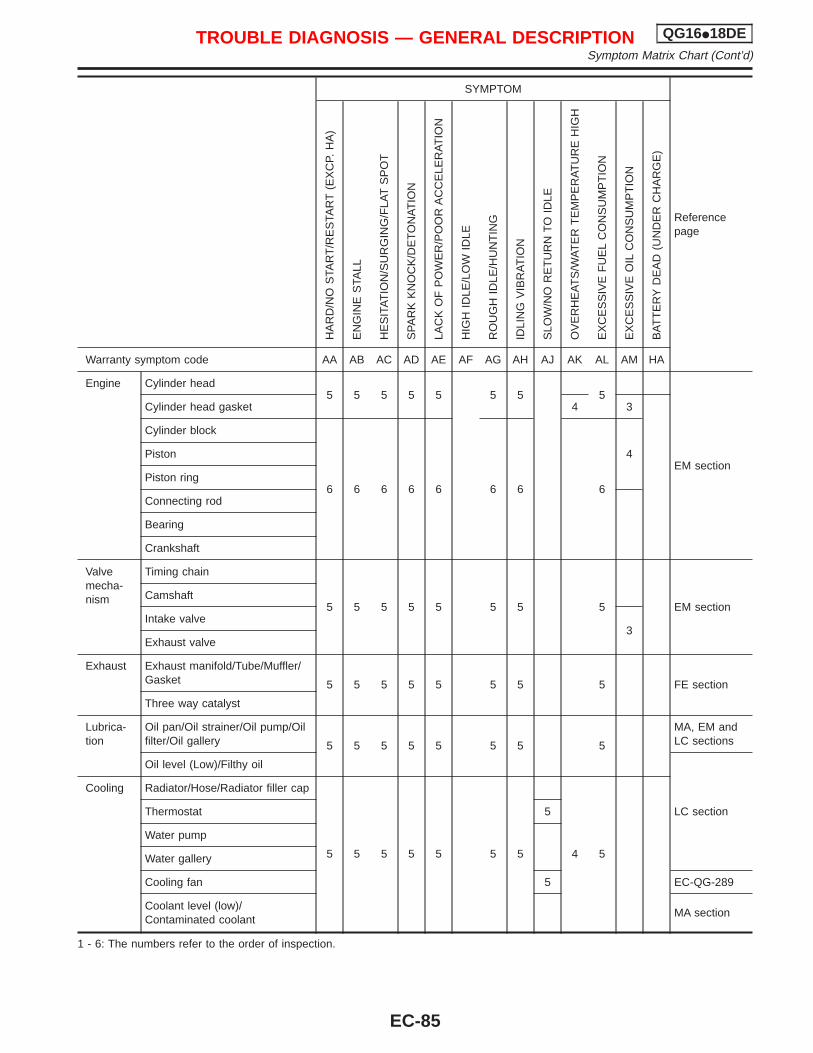
SYMPTOM
Referencepage
HA
RD
/NO
STA
RT
/RE
STA
RT
(EX
CP.
HA
)
EN
GIN
ES
TALL
HE
SIT
AT
ION
/SU
RG
ING
/FLA
TS
PO
T
SP
AR
KK
NO
CK
/DE
TO
NA
TIO
N
LAC
KO
FP
OW
ER
/PO
OR
AC
CE
LER
AT
ION
HIG
HID
LE/L
OW
IDLE
RO
UG
HID
LE/H
UN
TIN
G
IDLI
NG
VIB
RA
TIO
N
SLO
W/N
OR
ET
UR
NT
OID
LE
OV
ER
HE
AT
S/W
AT
ER
TE
MP
ER
AT
UR
EH
IGH
EX
CE
SS
IVE
FU
EL
CO
NS
UM
PT
ION
EX
CE
SS
IVE
OIL
CO
NS
UM
PT
ION
BA
TT
ER
YD
EA
D(U
ND
ER
CH
AR
GE
)
Warranty symptom code AA AB AC AD AE AF AG AH AJ AK AL AM HA
Engine Cylinder head5 5 5 5 5 5 5 5
EM section
Cylinder head gasket 4 3
Cylinder block
6 6 6 6 6 6 6 6
4Piston
Piston ring
Connecting rod
Bearing
Crankshaft
Valvemecha-nism
Timing chain
5 5 5 5 5 5 5 5 EM sectionCamshaft
Intake valve3
Exhaust valve
Exhaust Exhaust manifold/Tube/Muffler/Gasket 5 5 5 5 5 5 5 5 FE section
Three way catalyst
Lubrica-tion
Oil pan/Oil strainer/Oil pump/Oilfilter/Oil gallery 5 5 5 5 5 5 5 5
MA, EM andLC sections
Oil level (Low)/Filthy oil
LC section
Cooling Radiator/Hose/Radiator filler cap
5 5 5 5 5 5 5 4 5
Thermostat 5
Water pump
Water gallery
Cooling fan 5 EC-QG-289
Coolant level (low)/Contaminated coolant
MA section
1 - 6: The numbers refer to the order of inspection.
TROUBLE DIAGNOSIS — GENERAL DESCRIPTION QG16I18DESymptom Matrix Chart (Cont’d)
EC-85
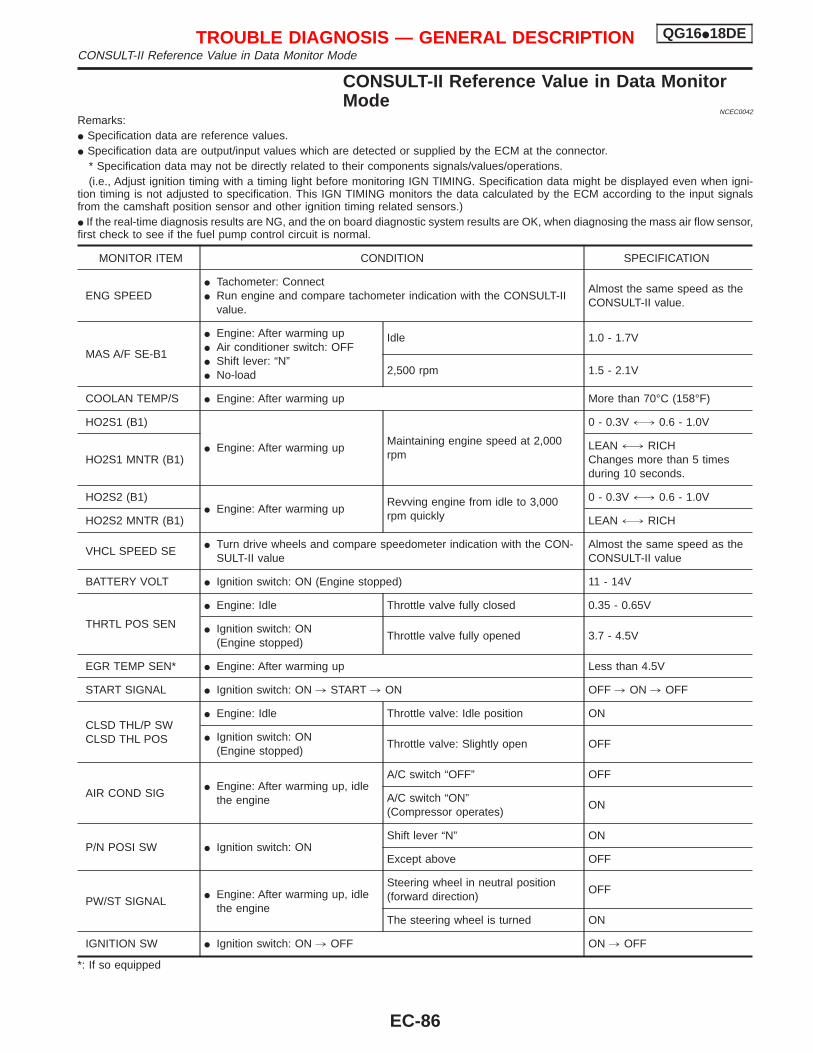
CONSULT-II Reference Value in Data MonitorMode
NCEC0042
Remarks:I Specification data are reference values.I Specification data are output/input values which are detected or supplied by the ECM at the connector.
* Specification data may not be directly related to their components signals/values/operations.(i.e., Adjust ignition timing with a timing light before monitoring IGN TIMING. Specification data might be displayed even when igni-
tion timing is not adjusted to specification. This IGN TIMING monitors the data calculated by the ECM according to the input signalsfrom the camshaft position sensor and other ignition timing related sensors.)I If the real-time diagnosis results are NG, and the on board diagnostic system results are OK, when diagnosing the mass air flow sensor,first check to see if the fuel pump control circuit is normal.
MONITOR ITEM CONDITION SPECIFICATION
ENG SPEEDI Tachometer: ConnectI Run engine and compare tachometer indication with the CONSULT-II
value.
Almost the same speed as theCONSULT-II value.
MAS A/F SE-B1
I Engine: After warming upI Air conditioner switch: OFFI Shift lever: “N”I No-load
Idle 1.0 - 1.7V
2,500 rpm 1.5 - 2.1V
COOLAN TEMP/S I Engine: After warming up More than 70°C (158°F)
HO2S1 (B1)
I Engine: After warming upMaintaining engine speed at 2,000rpm
0 - 0.3V +, 0.6 - 1.0V
HO2S1 MNTR (B1)LEAN +, RICHChanges more than 5 timesduring 10 seconds.
HO2S2 (B1)I Engine: After warming up
Revving engine from idle to 3,000rpm quickly
0 - 0.3V +, 0.6 - 1.0V
HO2S2 MNTR (B1) LEAN +, RICH
VHCL SPEED SEI Turn drive wheels and compare speedometer indication with the CON-
SULT-II valueAlmost the same speed as theCONSULT-II value
BATTERY VOLT I Ignition switch: ON (Engine stopped) 11 - 14V
THRTL POS SEN
I Engine: Idle Throttle valve fully closed 0.35 - 0.65V
I Ignition switch: ON(Engine stopped)
Throttle valve fully opened 3.7 - 4.5V
EGR TEMP SEN* I Engine: After warming up Less than 4.5V
START SIGNAL I Ignition switch: ON , START , ON OFF , ON , OFF
CLSD THL/P SWCLSD THL POS
I Engine: Idle Throttle valve: Idle position ON
I Ignition switch: ON(Engine stopped)
Throttle valve: Slightly open OFF
AIR COND SIGI Engine: After warming up, idle
the engine
A/C switch “OFF” OFF
A/C switch “ON”(Compressor operates)
ON
P/N POSI SW I Ignition switch: ONShift lever “N” ON
Except above OFF
PW/ST SIGNALI Engine: After warming up, idle
the engine
Steering wheel in neutral position(forward direction)
OFF
The steering wheel is turned ON
IGNITION SW I Ignition switch: ON , OFF ON , OFF
*: If so equipped
TROUBLE DIAGNOSIS — GENERAL DESCRIPTION QG16I18DECONSULT-II Reference Value in Data Monitor Mode
EC-86
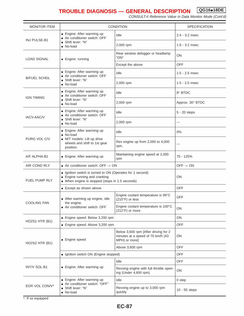
MONITOR ITEM CONDITION SPECIFICATION
INJ PULSE-B1
I Engine: After warming upI Air conditioner switch: OFFI Shift lever: “N”I No-load
Idle 2.4 - 3.2 msec
2,000 rpm 1.9 - 3.2 msec
LOAD SIGNAL I Engine: running
Rear window defogger or headlamp“ON”
ON
Except the above OFF
B/FUEL SCHDL
I Engine: After warming upI Air conditioner switch: OFFI Shift lever: “N”I No-load
Idle 1.5 - 2.5 msec
2,000 rpm 1.5 - 2.5 msec
IGN TIMING
I Engine: After warming upI Air conditioner switch: OFFI Shift lever: “N”I No-load
Idle 8° BTDC
2,000 rpm Approx. 30° BTDC
IACV-AAC/V
I Engine: After warming upI Air conditioner switch: OFFI Shift lever: “N”I No-load
Idle 5 - 20 steps
2,000 rpm —
PURG VOL C/V
I Engine: After warming upI No-loadI M/T models: Lift up drive
wheels and shift to 1st gearposition.
Idle 0%
Rev engine up from 2,000 to 4,000rpm.
—
A/F ALPHA-B1 I Engine: After warming upMaintaining engine speed at 2,000rpm
75 - 125%
AIR COND RLY I Air conditioner switch: OFF , ON OFF , ON
FUEL PUMP RLY
I Ignition switch is turned to ON (Operates for 1 second)I Engine running and crankingI When engine is stopped (stops in 1.5 seconds)
ON
I Except as shown above OFF
COOLING FANI After warming up engine, idle
the engine.I Air conditioner switch: OFF
Engine coolant temperature is 99°C(210°F) or less
OFF
Engine coolant temperature is 100°C(212°F) or more
ON
HO2S1 HTR (B1)I Engine speed: Below 3,200 rpm ON
I Engine speed: Above 3,200 rpm OFF
HO2S2 HTR (B1)I Engine speed
Below 3,600 rpm [After driving for 2minutes at a speed of 70 km/h (43MPH) or more]
ON
Above 3,600 rpm OFF
I Ignition switch ON (Engine stopped) OFF
INT/V SOL-B1 I Engine: After warming up
Idle OFF
Revving engine with full throttle open-ing (Under 4,600 rpm)
ON
EGR VOL CON/V*
I Engine: After warming upI Air conditioner switch: “OFF”I Shift lever: “N”I No-load
Idle 0 step
Revving engine up to 3,000 rpmquickly
10 - 55 steps
*: If so equipped
TROUBLE DIAGNOSIS — GENERAL DESCRIPTION QG16I18DECONSULT-II Reference Value in Data Monitor Mode (Cont’d)
EC-87
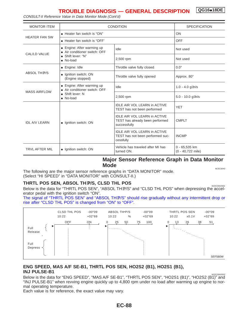
MONITOR ITEM CONDITION SPECIFICATION
HEATER FAN SWI Heater fan switch is “ON” ON
I Heater fan switch is “OFF’ OFF
CAL/LD VALUE
I Engine: After warming upI Air conditioner switch: OFFI Shift lever: “N”I No-load
Idle Not used
2,500 rpm Not used
ABSOL TH⋅P/S
I Engine: Idle Throttle valve fully closed 0.0°
I Ignition switch: ON(Engine stopped)
Throttle valve fully opened Approx. 80°
MASS AIRFLOW
I Engine: After warming upI Air conditioner switch: OFFI Shift lever: NI No-load
Idle 1.0 - 4.0 g⋅m/s
2,500 rpm 5.0 - 10.0 g⋅m/s
IDL A/V LEARN I Ignition switch: ON
IDLE AIR VOL LEARN in ACTIVETEST has not been performed
YET
IDLE AIR VOL LEARN in ACTIVETEST has already been performedsuccessfully
CMPLT
IDLE AIR VOL LEARN in ACTIVETEST has not been performed suc-cessfully
INCMP
TRVL AFTER MIL I Ignition switch: ONVehicle has traveled after MI hasturned ON.
0 - 65,535 km(0 - 40,722 mile)
Major Sensor Reference Graph in Data MonitorMode
NCEC0043
The following are the major sensor reference graphs in “DATA MONITOR” mode.(Select “HI SPEED” in “DATA MONITOR” with CONSULT-II.)
THRTL POS SEN, ABSOL TH ⋅P/S, CLSD THL POSNCEC0043S01
Below is the data for “THRTL POS SEN”, “ABSOL TH⋅P/S” and “CLSD THL POS” when depressing the accel-erator pedal with the ignition switch “ON”.The signal of “THRTL POS SEN” and “ABSOL TH⋅P/S” should rise gradually without any intermittent drop orrise after “CLSD THL POS” is changed from “ON” to “OFF”.
ENG SPEED, MAS A/F SE-B1, THRTL POS SEN, HO2S2 (B1), HO2S1 (B1),INJ PULSE-B1
NCEC0043S02
Below is the data for “ENG SPEED”, “MAS A/F SE-B1”, “THRTL POS SEN”, “HO2S1 (B1)”, “HO2S2 (B1)” and“INJ PULSE-B1” when revving engine quickly up to 4,800 rpm under no load after warming up engine to nor-mal operating temperature.Each value is for reference, the exact value may vary.
FullRelease
FullDepress
CLSD THL POS -00"09 ABSOL TH P/S -00"09 THRTL POS SEN -00"09
10:22 +02"69 10:22 % +02"69 10:22 x0.1V +02"69
OFF ON 0 25 50 75 100 0 13 26 38 51
SEF580W
TROUBLE DIAGNOSIS — GENERAL DESCRIPTION QG16I18DECONSULT-II Reference Value in Data Monitor Mode (Cont’d)
EC-88
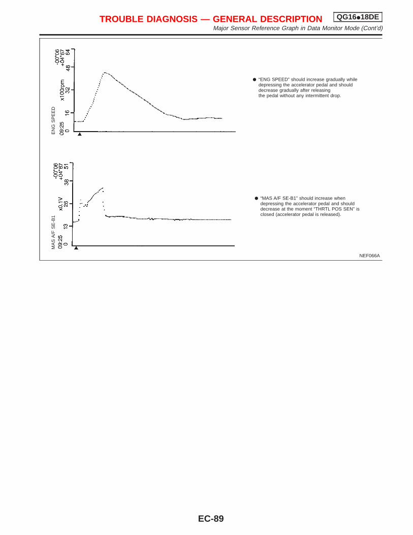
NEF066A
“ENG SPEED” should increase gradually whiledepressing the accelerator pedal and shoulddecrease gradually after releasingthe pedal without any intermittent drop.
“MAS A/F SE-B1” should increase whendepressing the accelerator pedal and shoulddecrease at the moment “THRTL POS SEN” isclosed (accelerator pedal is released).
MA
SA
/FS
E-B
1E
NG
SP
EE
D
TROUBLE DIAGNOSIS — GENERAL DESCRIPTION QG16I18DEMajor Sensor Reference Graph in Data Monitor Mode (Cont’d)
EC-89
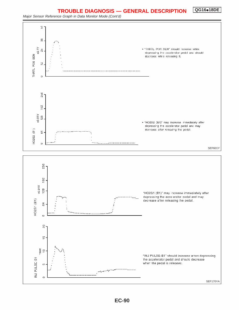
SEF601Y
SEF170YA
TROUBLE DIAGNOSIS — GENERAL DESCRIPTION QG16I18DEMajor Sensor Reference Graph in Data Monitor Mode (Cont’d)
EC-90
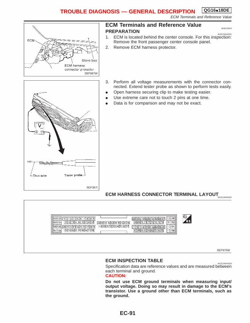
ECM Terminals and Reference ValueNCEC0044
PREPARATIONNCEC0044S01
1. ECM is located behind the center console. For this inspection:Remove the front passenger center console panel.
2. Remove ECM harness protector.
3. Perform all voltage measurements with the connector con-nected. Extend tester probe as shown to perform tests easily.
I Open harness securing clip to make testing easier.I Use extreme care not to touch 2 pins at one time.I Data is for comparison and may not be exact.
ECM HARNESS CONNECTOR TERMINAL LAYOUTNCEC0044S02
ECM INSPECTION TABLENCEC0044S03
Specification data are reference values and are measured betweeneach terminal and ground.CAUTION:Do not use ECM ground terminals when measuring input/output voltage. Doing so may result in damage to the ECM’stransistor. Use a ground other than ECM terminals, such asthe ground.
SEF967W
SEF367I
SEF970W
TROUBLE DIAGNOSIS — GENERAL DESCRIPTION QG16I18DEECM Terminals and Reference Value
EC-91
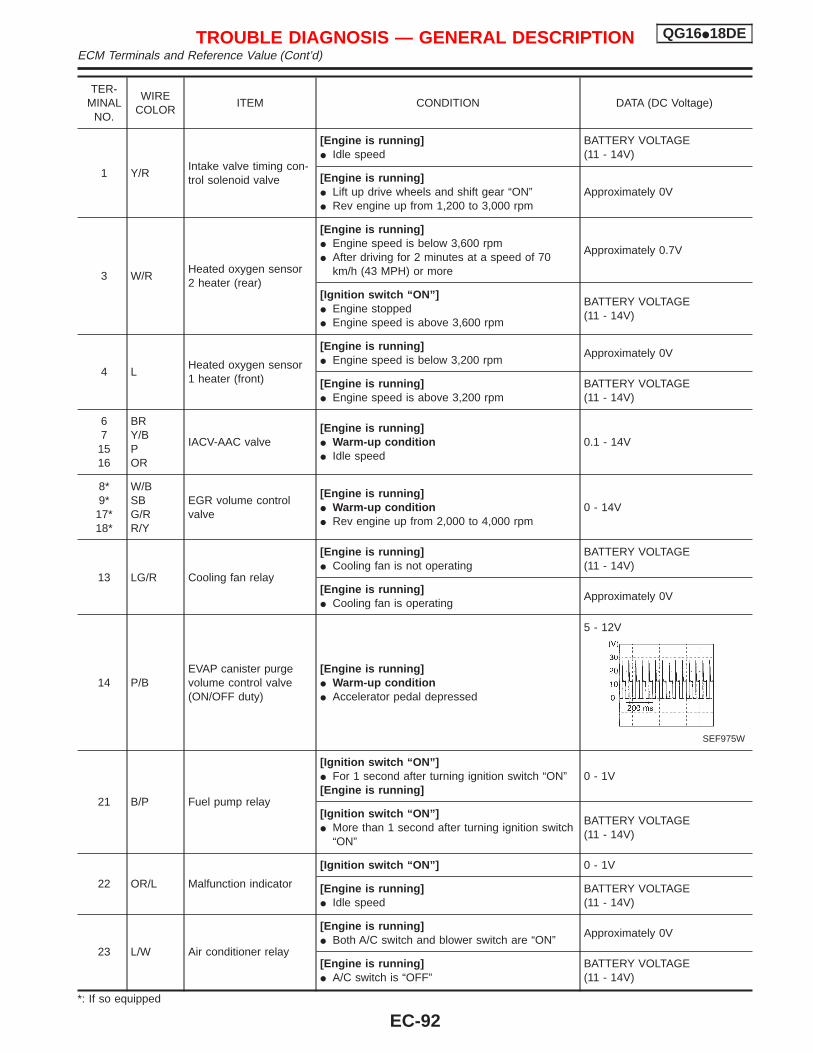
TER-MINAL
NO.
WIRECOLOR
ITEM CONDITION DATA (DC Voltage)
1 Y/RIntake valve timing con-trol solenoid valve
[Engine is running]I Idle speed
BATTERY VOLTAGE(11 - 14V)
[Engine is running]I Lift up drive wheels and shift gear “ON”I Rev engine up from 1,200 to 3,000 rpm
Approximately 0V
3 W/RHeated oxygen sensor2 heater (rear)
[Engine is running]I Engine speed is below 3,600 rpmI After driving for 2 minutes at a speed of 70
km/h (43 MPH) or more
Approximately 0.7V
[Ignition switch “ON”]I Engine stoppedI Engine speed is above 3,600 rpm
BATTERY VOLTAGE(11 - 14V)
4 LHeated oxygen sensor1 heater (front)
[Engine is running]I Engine speed is below 3,200 rpm
Approximately 0V
[Engine is running]I Engine speed is above 3,200 rpm
BATTERY VOLTAGE(11 - 14V)
67
1516
BRY/BPOR
IACV-AAC valve[Engine is running]I Warm-up conditionI Idle speed
0.1 - 14V
8*9*17*18*
W/BSBG/RR/Y
EGR volume controlvalve
[Engine is running]I Warm-up conditionI Rev engine up from 2,000 to 4,000 rpm
0 - 14V
13 LG/R Cooling fan relay
[Engine is running]I Cooling fan is not operating
BATTERY VOLTAGE(11 - 14V)
[Engine is running]I Cooling fan is operating
Approximately 0V
14 P/BEVAP canister purgevolume control valve(ON/OFF duty)
[Engine is running]I Warm-up conditionI Accelerator pedal depressed
5 - 12V
SEF975W
21 B/P Fuel pump relay
[Ignition switch “ON”]I For 1 second after turning ignition switch “ON”[Engine is running]
0 - 1V
[Ignition switch “ON”]I More than 1 second after turning ignition switch
“ON”
BATTERY VOLTAGE(11 - 14V)
22 OR/L Malfunction indicator
[Ignition switch “ON”] 0 - 1V
[Engine is running]I Idle speed
BATTERY VOLTAGE(11 - 14V)
23 L/W Air conditioner relay
[Engine is running]I Both A/C switch and blower switch are “ON”
Approximately 0V
[Engine is running]I A/C switch is “OFF”
BATTERY VOLTAGE(11 - 14V)
*: If so equipped
TROUBLE DIAGNOSIS — GENERAL DESCRIPTION QG16I18DEECM Terminals and Reference Value (Cont’d)
EC-92
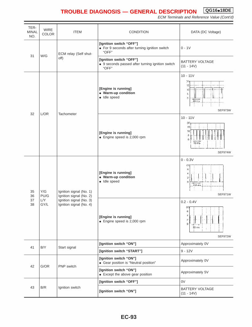
TER-MINAL
NO.
WIRECOLOR
ITEM CONDITION DATA (DC Voltage)
31 W/GECM relay (Self shut-off)
[Ignition switch “OFF”]I For 9 seconds after turning ignition switch
“OFF”0 - 1V
[Ignition switch “OFF”]I 9 seconds passed after turning ignition switch
“OFF”
BATTERY VOLTAGE(11 - 14V)
32 L/OR Tachometer
[Engine is running]I Warm-up conditionI Idle speed
10 - 11V
SEF973W
[Engine is running]I Engine speed is 2,000 rpm
10 - 11V
SEF974W
35363738
Y/GPU/GL/YGY/L
Ignition signal (No. 1)Ignition signal (No. 2)Ignition signal (No. 3)Ignition signal (No. 4)
[Engine is running]I Warm-up conditionI Idle speed
0 - 0.3V
SEF971W
[Engine is running]I Engine speed is 2,000 rpm
0.2 - 0.4V
SEF972W
41 B/Y Start signal[Ignition switch “ON”] Approximately 0V
[Ignition switch “START”] 9 - 12V
42 G/OR PNP switch
[Ignition switch “ON”]I Gear position is “Neutral position”
Approximately 0V
[Ignition switch “ON”]I Except the above gear position
Approximately 5V
43 B/R Ignition switch
[Ignition switch “OFF”] 0V
[Ignition switch “ON”]BATTERY VOLTAGE(11 - 14V)
TROUBLE DIAGNOSIS — GENERAL DESCRIPTION QG16I18DEECM Terminals and Reference Value (Cont’d)
EC-93
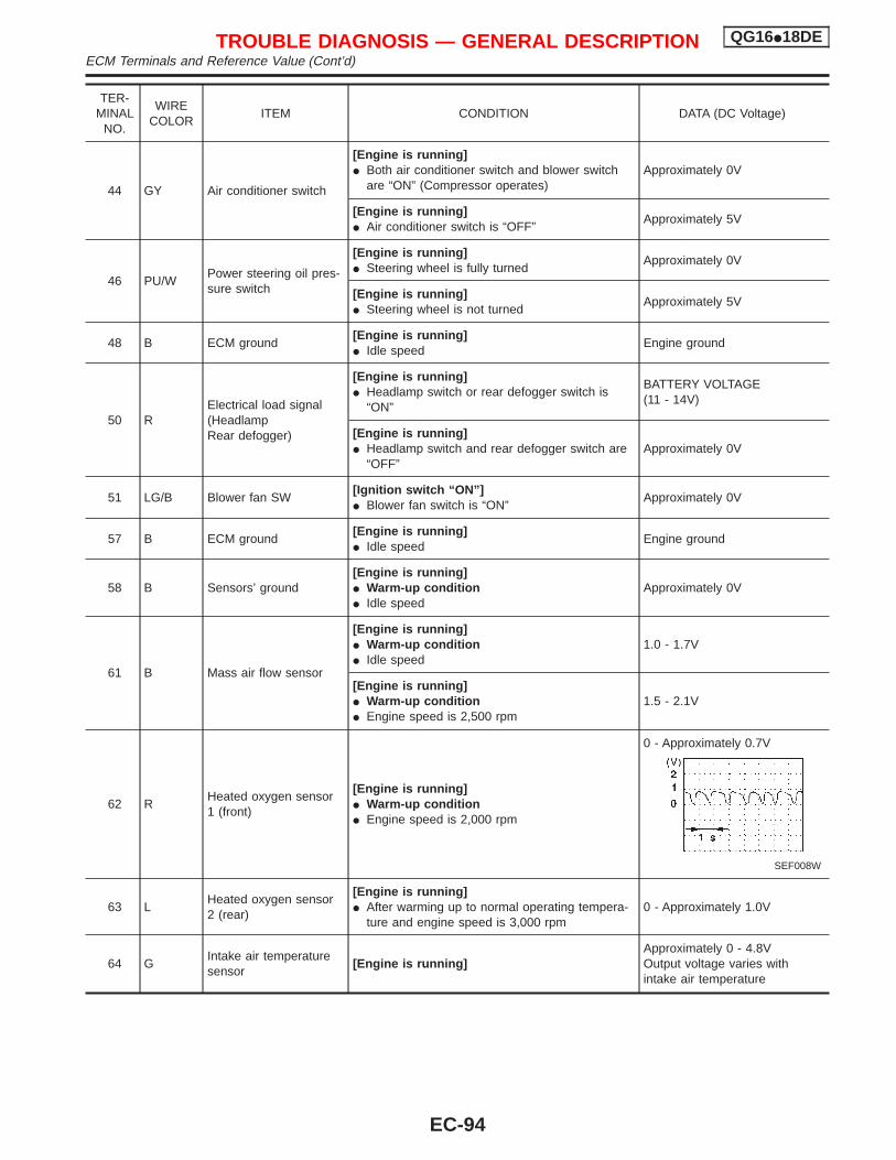
TER-MINAL
NO.
WIRECOLOR
ITEM CONDITION DATA (DC Voltage)
44 GY Air conditioner switch
[Engine is running]I Both air conditioner switch and blower switch
are “ON” (Compressor operates)Approximately 0V
[Engine is running]I Air conditioner switch is “OFF”
Approximately 5V
46 PU/WPower steering oil pres-sure switch
[Engine is running]I Steering wheel is fully turned
Approximately 0V
[Engine is running]I Steering wheel is not turned
Approximately 5V
48 B ECM ground[Engine is running]I Idle speed
Engine ground
50 RElectrical load signal(HeadlampRear defogger)
[Engine is running]I Headlamp switch or rear defogger switch is
“ON”
BATTERY VOLTAGE(11 - 14V)
[Engine is running]I Headlamp switch and rear defogger switch are
“OFF”Approximately 0V
51 LG/B Blower fan SW[Ignition switch “ON”]I Blower fan switch is “ON”
Approximately 0V
57 B ECM ground[Engine is running]I Idle speed
Engine ground
58 B Sensors’ ground[Engine is running]I Warm-up conditionI Idle speed
Approximately 0V
61 B Mass air flow sensor
[Engine is running]I Warm-up conditionI Idle speed
1.0 - 1.7V
[Engine is running]I Warm-up conditionI Engine speed is 2,500 rpm
1.5 - 2.1V
62 RHeated oxygen sensor1 (front)
[Engine is running]I Warm-up conditionI Engine speed is 2,000 rpm
0 - Approximately 0.7V
SEF008W
63 LHeated oxygen sensor2 (rear)
[Engine is running]I After warming up to normal operating tempera-
ture and engine speed is 3,000 rpm0 - Approximately 1.0V
64 GIntake air temperaturesensor
[Engine is running]Approximately 0 - 4.8VOutput voltage varies withintake air temperature
TROUBLE DIAGNOSIS — GENERAL DESCRIPTION QG16I18DEECM Terminals and Reference Value (Cont’d)
EC-94
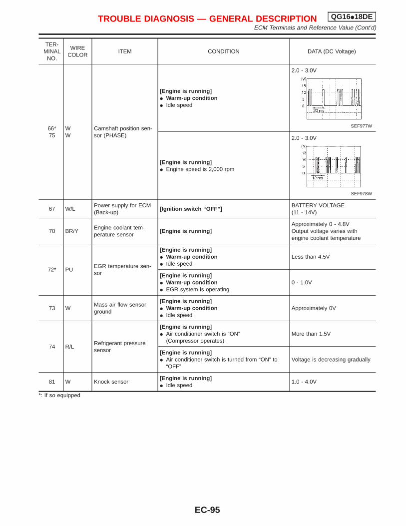
TER-MINAL
NO.
WIRECOLOR
ITEM CONDITION DATA (DC Voltage)
66*75
WW
Camshaft position sen-sor (PHASE)
[Engine is running]I Warm-up conditionI Idle speed
2.0 - 3.0V
SEF977W
[Engine is running]I Engine speed is 2,000 rpm
2.0 - 3.0V
SEF978W
67 W/LPower supply for ECM(Back-up)
[Ignition switch “OFF”]BATTERY VOLTAGE(11 - 14V)
70 BR/YEngine coolant tem-perature sensor
[Engine is running]Approximately 0 - 4.8VOutput voltage varies withengine coolant temperature
72* PUEGR temperature sen-sor
[Engine is running]I Warm-up conditionI Idle speed
Less than 4.5V
[Engine is running]I Warm-up conditionI EGR system is operating
0 - 1.0V
73 WMass air flow sensorground
[Engine is running]I Warm-up conditionI Idle speed
Approximately 0V
74 R/LRefrigerant pressuresensor
[Engine is running]I Air conditioner switch is “ON”
(Compressor operates)More than 1.5V
[Engine is running]I Air conditioner switch is turned from “ON” to
“OFF”Voltage is decreasing gradually
81 W Knock sensor[Engine is running]I Idle speed
1.0 - 4.0V
*: If so equipped
TROUBLE DIAGNOSIS — GENERAL DESCRIPTION QG16I18DEECM Terminals and Reference Value (Cont’d)
EC-95
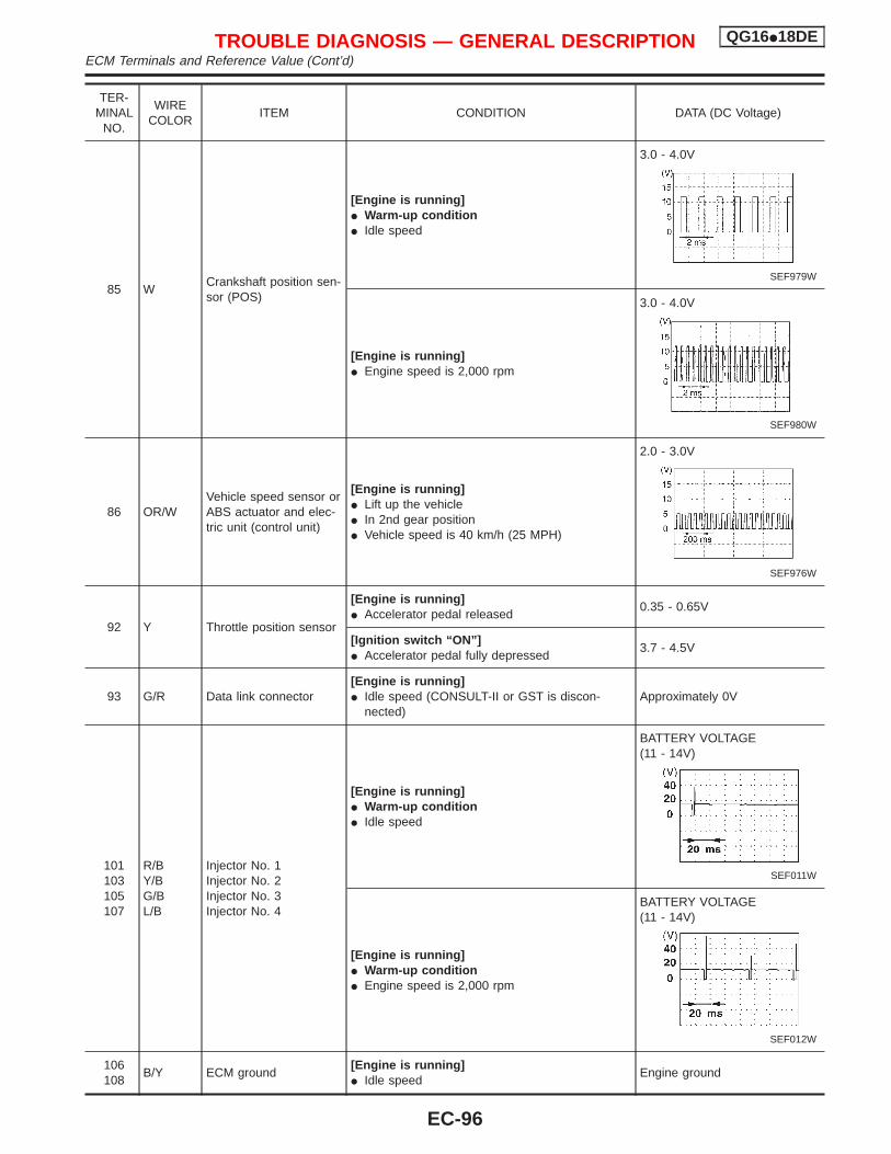
TER-MINAL
NO.
WIRECOLOR
ITEM CONDITION DATA (DC Voltage)
85 WCrankshaft position sen-sor (POS)
[Engine is running]I Warm-up conditionI Idle speed
3.0 - 4.0V
SEF979W
[Engine is running]I Engine speed is 2,000 rpm
3.0 - 4.0V
SEF980W
86 OR/WVehicle speed sensor orABS actuator and elec-tric unit (control unit)
[Engine is running]I Lift up the vehicleI In 2nd gear positionI Vehicle speed is 40 km/h (25 MPH)
2.0 - 3.0V
SEF976W
92 Y Throttle position sensor
[Engine is running]I Accelerator pedal released
0.35 - 0.65V
[Ignition switch “ON”]I Accelerator pedal fully depressed
3.7 - 4.5V
93 G/R Data link connector[Engine is running]I Idle speed (CONSULT-II or GST is discon-
nected)Approximately 0V
101103105107
R/BY/BG/BL/B
Injector No. 1Injector No. 2Injector No. 3Injector No. 4
[Engine is running]I Warm-up conditionI Idle speed
BATTERY VOLTAGE(11 - 14V)
SEF011W
[Engine is running]I Warm-up conditionI Engine speed is 2,000 rpm
BATTERY VOLTAGE(11 - 14V)
SEF012W
106108
B/Y ECM ground[Engine is running]I Idle speed
Engine ground
TROUBLE DIAGNOSIS — GENERAL DESCRIPTION QG16I18DEECM Terminals and Reference Value (Cont’d)
EC-96
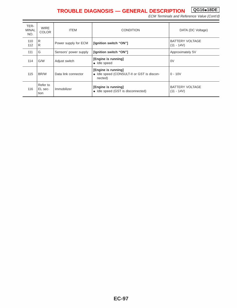
TER-MINAL
NO.
WIRECOLOR
ITEM CONDITION DATA (DC Voltage)
110112
RR
Power supply for ECM [Ignition switch “ON”]BATTERY VOLTAGE(11 - 14V)
111 G Sensors’ power supply [Ignition switch “ON”] Approximately 5V
114 G/W Adjust switch[Engine is running]I Idle speed
0V
115 BR/W Data link connector[Engine is running]I Idle speed (CONSULT-II or GST is discon-
nected)0 - 10V
116Refer toEL sec-tion
Immobilizer[Engine is running]I Idle speed (GST is disconnected)
BATTERY VOLTAGE(11 - 14V)
TROUBLE DIAGNOSIS — GENERAL DESCRIPTION QG16I18DEECM Terminals and Reference Value (Cont’d)
EC-97
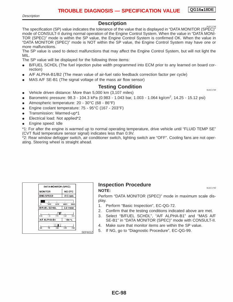
DescriptionNLEC1748
The specification (SP) value indicates the tolerance of the value that is displayed in “DATA MONITOR (SPEC)”mode of CONSULT-II during normal operation of the Engine Control System. When the value in “DATA MONI-TOR (SPEC)” mode is within the SP value, the Engine Control System is confirmed OK. When the value in“DATA MONITOR (SPEC)” mode is NOT within the SP value, the Engine Control System may have one ormore malfunctions.The SP value is used to detect malfunctions that may affect the Engine Control System, but will not light theMIL.The SP value will be displayed for the following three items:I B/FUEL SCHDL (The fuel injection pulse width programmed into ECM prior to any learned on board cor-
rection)I A/F ALPHA-B1/B2 (The mean value of air-fuel ratio feedback correction factor per cycle)I MAS A/F SE-B1 (The signal voltage of the mass air flow sensor)
Testing ConditionNLEC1749
I Vehicle driven distance: More than 5,000 km (3,107 miles)I Barometric pressure: 98.3 - 104.3 kPa (0.983 - 1.043 bar, 1.003 - 1.064 kg/cm2, 14.25 - 15.12 psi)I Atmospheric temperature: 20 - 30°C (68 - 86°F)I Engine coolant temperature: 75 - 95°C (167 - 203°F)I Transmission: Warmed-up*1I Electrical load: Not applied*2I Engine speed: Idle*1: For after the engine is warmed up to normal operating temperature, drive vehicle until “FLUID TEMP SE”(CVT fluid temperature sensor signal) indicates less than 0.9V.*2: Rear window defogger switch, air conditioner switch, lighting switch are “OFF”. Cooling fans are not oper-ating. Steering wheel is straight ahead.
SEF601Z
Inspection ProcedureNLEC1750
NOTE:Perform “DATA MONITOR (SPEC)” mode in maximum scale dis-play.1. Perform “Basic Inspection”, EC-QG-72.2. Confirm that the testing conditions indicated above are met.3. Select “B/FUEL SCHDL”, “A/F ALPHA-B1” and “MAS A/F
SE-B1” in “DATA MONITOR (SPEC)” mode with CONSULT-II.4. Make sure that monitor items are within the SP value.5. If NG, go to “Diagnostic Procedure”, EC-QG-99.
TROUBLE DIAGNOSIS — SPECIFICATION VALUE QG16I18DEDescription
EC-98
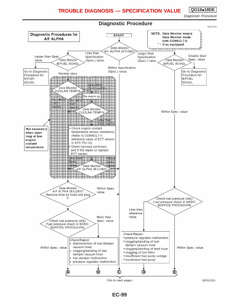
Diagnostic ProcedureNLEC1751
SEF613ZA
TROUBLE DIAGNOSIS — SPECIFICATION VALUE QG16I18DEDiagnostic Procedure
EC-99
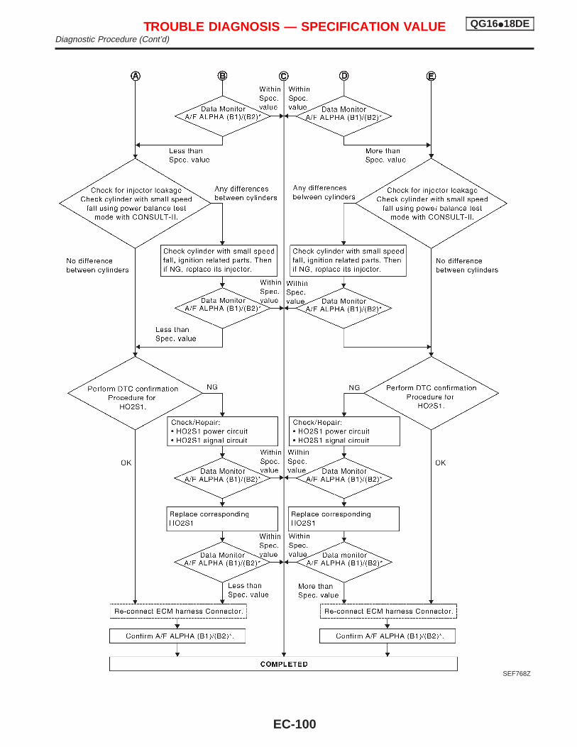
SEF768Z
TROUBLE DIAGNOSIS — SPECIFICATION VALUE QG16I18DEDiagnostic Procedure (Cont’d)
EC-100
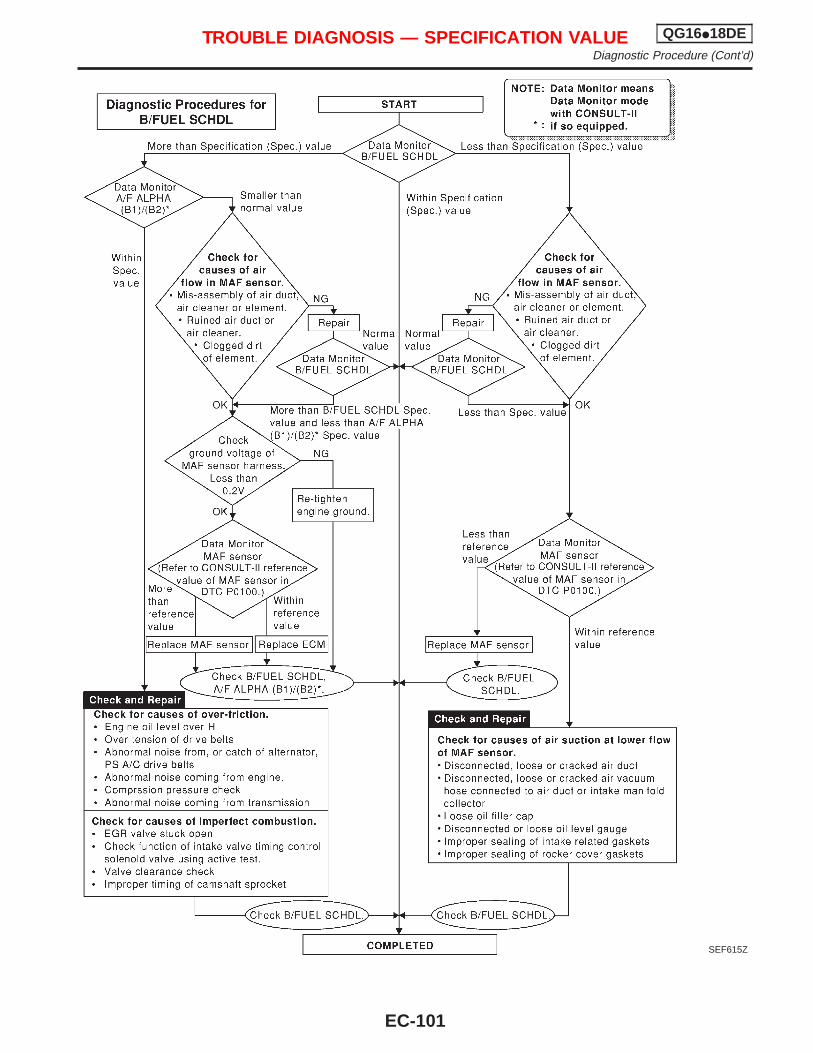
SEF615Z
TROUBLE DIAGNOSIS — SPECIFICATION VALUE QG16I18DEDiagnostic Procedure (Cont’d)
EC-101
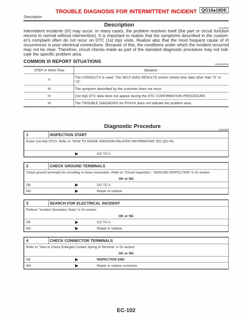
DescriptionNCEC0045
Intermittent incidents (I/I) may occur. In many cases, the problem resolves itself (the part or circuit functionreturns to normal without intervention). It is important to realize that the symptoms described in the custom-er’s complaint often do not recur on DTC (1st trip) visits. Realize also that the most frequent cause of I/Ioccurrences is poor electrical connections. Because of this, the conditions under which the incident occurredmay not be clear. Therefore, circuit checks made as part of the standard diagnostic procedure may not indi-cate the specific problem area.
COMMON I/I REPORT SITUATIONSNCEC0045S01
STEP in Work Flow Situation
IIThe CONSULT-II is used. The SELF-DIAG RESULTS screen shows time data other than “0” or“1t”.
III The symptom described by the customer does not recur.
IV (1st trip) DTC data does not appear during the DTC CONFIRMATION PROCEDURE.
VI The TROUBLE DIAGNOSIS for PXXXX does not indicate the problem area.
Diagnostic ProcedureNCEC0046
1 INSPECTION START
Erase (1st trip) DTCs. Refer to “HOW TO ERASE EMISSION-RELATED INFORMATION” (EC-QG-44).
© GO TO 2.
2 CHECK GROUND TERMINALS
Check ground terminals for corroding or loose connection. Refer to “Circuit Inspection”, “GROUND INSPECTION” in GI section.
OK or NG
OK © GO TO 3.
NG © Repair or replace.
3 SEARCH FOR ELECTRICAL INCIDENT
Perform “Incident Simulation Tests” in GI section.
OK or NG
OK © GO TO 4.
NG © Repair or replace.
4 CHECK CONNECTOR TERMINALS
Refer to “How to Check Enlarged Contact Spring of Terminal” in GI section.
OK or NG
OK © INSPECTION END
NG © Repair or replace connector.
TROUBLE DIAGNOSIS FOR INTERMITTENT INCIDENT QG16I18DEDescription
EC-102
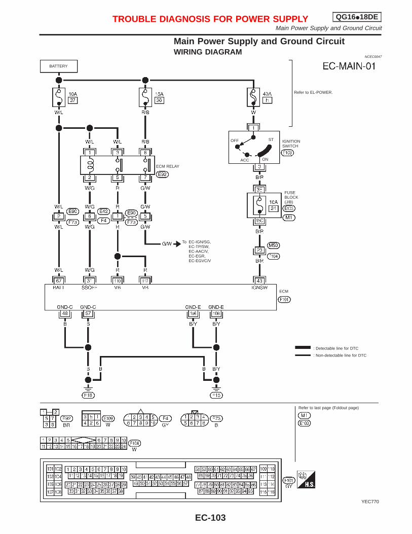
Main Power Supply and Ground CircuitWIRING DIAGRAM
NCEC0047
YEC770
BATTERY
Refer to EL-POWER.
OFF
ACC
ST
ON
IGNITIONSWITCH
FUSEBLOCK(J/B)
To EC-IGN/SG,EC-TP/SW,EC-AAC/V,EC-EGR,EC-EGVC/V
ECM RELAY
: Detectable line for DTC
: Non-detectable line for DTC
Refer to last page (Foldout page)
ECM
TROUBLE DIAGNOSIS FOR POWER SUPPLY QG16I18DEMain Power Supply and Ground Circuit
EC-103
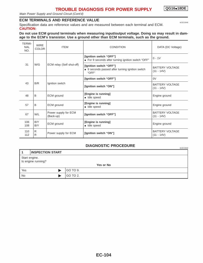
ECM TERMINALS AND REFERENCE VALUENCEC0048
Specification data are reference values and are measured between each terminal and ECM.CAUTION:Do not use ECM ground terminals when measuring input/output voltage. Doing so may result in dam-age to the ECM’s transistor. Use a ground other than ECM terminals, such as the ground.
TERMI-NALNO.
WIRECOLOR
ITEM CONDITION DATA (DC Voltage)
31 W/G ECM relay (Self shut-off)
[Ignition switch “OFF”]I For 9 seconds after turning ignition switch “OFF”
0 - 1V
[Ignition switch “OFF”]I 9 seconds passed after turning ignition switch
“OFF”
BATTERY VOLTAGE(11 - 14V)
43 B/R Ignition switch
[Ignition switch “OFF”] 0V
[Ignition switch “ON”]BATTERY VOLTAGE(11 - 14V)
48 B ECM ground[Engine is running]I Idle speed
Engine ground
57 B ECM ground[Engine is running]I Idle speed
Engine ground
67 W/LPower supply for ECM(Back-up)
[Ignition switch “OFF”]BATTERY VOLTAGE(11 - 14V)
106108
B/YB/Y
ECM ground[Engine is running]I Idle speed
Engine ground
110112
RR
Power supply for ECM [Ignition switch “ON”]BATTERY VOLTAGE(11 - 14V)
DIAGNOSTIC PROCEDURENCEC0049
1 INSPECTION START
Start engine.Is engine running?
Yes or No
Yes © GO TO 9.
No © GO TO 2.
TROUBLE DIAGNOSIS FOR POWER SUPPLY QG16I18DEMain Power Supply and Ground Circuit (Cont’d)
EC-104
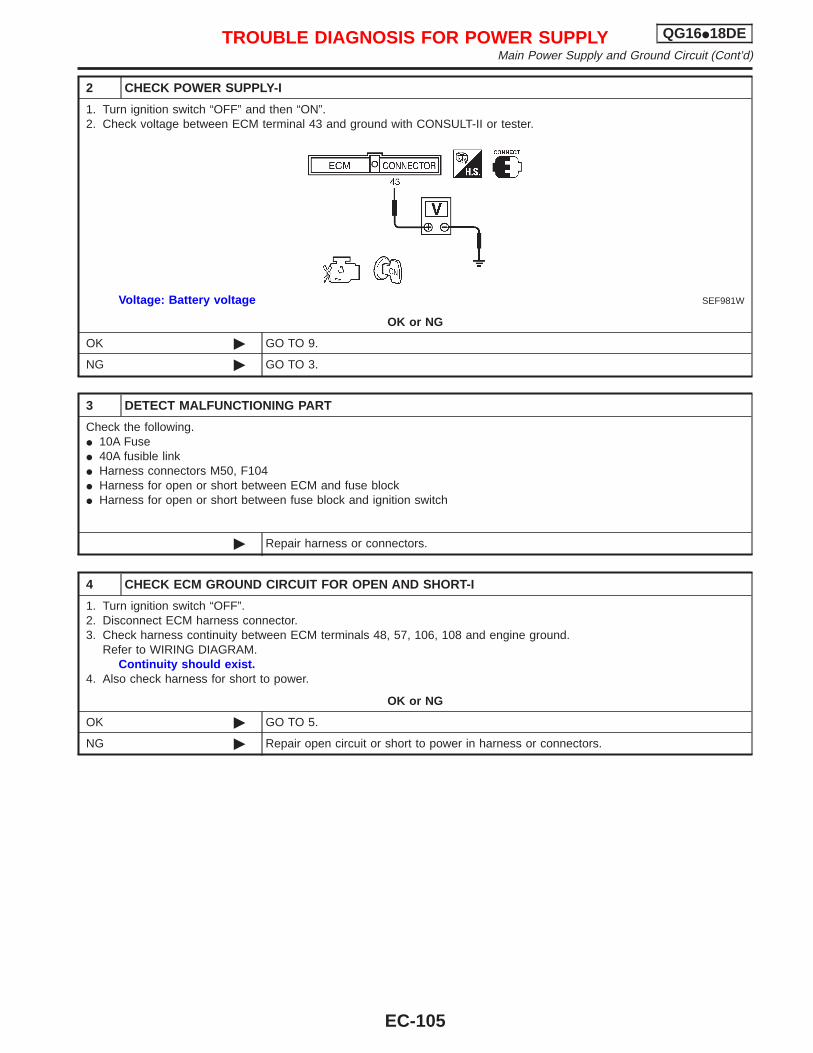
2 CHECK POWER SUPPLY-I
1. Turn ignition switch “OFF” and then “ON”.2. Check voltage between ECM terminal 43 and ground with CONSULT-II or tester.
SEF981WVoltage: Battery voltage
OK or NG
OK © GO TO 9.
NG © GO TO 3.
3 DETECT MALFUNCTIONING PART
Check the following.I 10A FuseI 40A fusible linkI Harness connectors M50, F104I Harness for open or short between ECM and fuse blockI Harness for open or short between fuse block and ignition switch
© Repair harness or connectors.
4 CHECK ECM GROUND CIRCUIT FOR OPEN AND SHORT-I
1. Turn ignition switch “OFF”.2. Disconnect ECM harness connector.3. Check harness continuity between ECM terminals 48, 57, 106, 108 and engine ground.
Refer to WIRING DIAGRAM.Continuity should exist.
4. Also check harness for short to power.
OK or NG
OK © GO TO 5.
NG © Repair open circuit or short to power in harness or connectors.
TROUBLE DIAGNOSIS FOR POWER SUPPLY QG16I18DEMain Power Supply and Ground Circuit (Cont’d)
EC-105
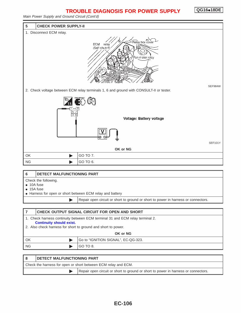
5 CHECK POWER SUPPLY-II
1. Disconnect ECM relay.
SEF984W
2. Check voltage between ECM relay terminals 1, 6 and ground with CONSULT-II or tester.
SEF101Y
OK or NG
OK © GO TO 7.
NG © GO TO 6.
6 DETECT MALFUNCTIONING PART
Check the following.I 10A fuseI 15A fuseI Harness for open or short between ECM relay and battery
© Repair open circuit or short to ground or short to power in harness or connectors.
7 CHECK OUTPUT SIGNAL CIRCUIT FOR OPEN AND SHORT
1. Check harness continuity between ECM terminal 31 and ECM relay terminal 2.Continuity should exist.
2. Also check harness for short to ground and short to power.
OK or NG
OK © Go to “IGNITION SIGNAL”, EC-QG-323.
NG © GO TO 8.
8 DETECT MALFUNCTIONING PART
Check the harness for open or short between ECM relay and ECM.
© Repair open circuit or short to ground or short to power in harness or connectors.
TROUBLE DIAGNOSIS FOR POWER SUPPLY QG16I18DEMain Power Supply and Ground Circuit (Cont’d)
EC-106
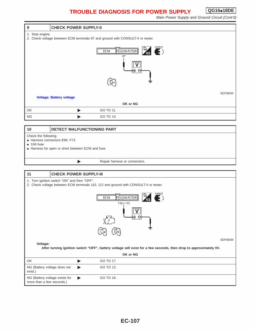
9 CHECK POWER SUPPLY-II
1. Stop engine.2. Check voltage between ECM terminals 67 and ground with CONSULT-II or tester.
SEF982WVoltage: Battery voltage
OK or NG
OK © GO TO 11.
NG © GO TO 10.
10 DETECT MALFUNCTIONING PART
Check the following.I Harness connectors E90, F73I 10A fuseI Harness for open or short between ECM and fuse
© Repair harness or connectors.
11 CHECK POWER SUPPLY-III
1. Turn ignition switch “ON” and then “OFF”.2. Check voltage between ECM terminals 110, 112 and ground with CONSULT-II or tester.
SEF983WVoltage:
After turning ignition switch “OFF”, battery voltage will exist for a few seconds, then drop to approximately 0V.
OK or NG
OK © GO TO 17.
NG (Battery voltage does notexist.)
© GO TO 12.
NG (Battery voltage exists formore than a few seconds.)
© GO TO 16.
TROUBLE DIAGNOSIS FOR POWER SUPPLY QG16I18DEMain Power Supply and Ground Circuit (Cont’d)
EC-107
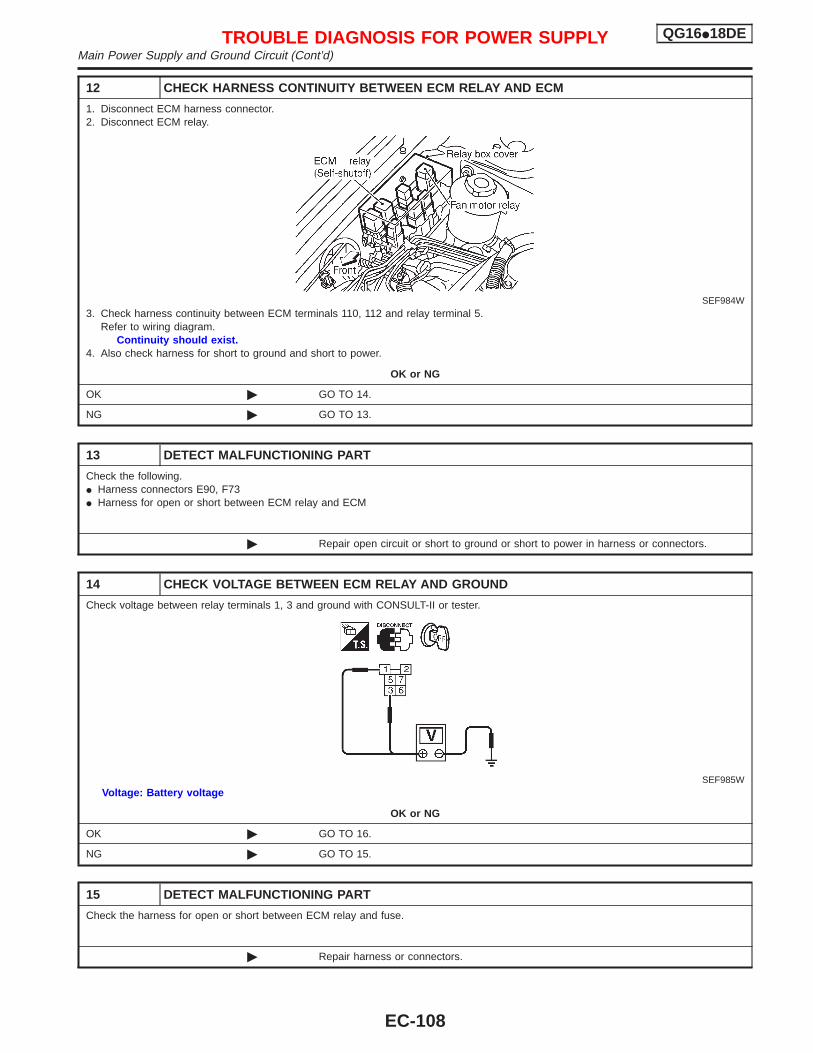
12 CHECK HARNESS CONTINUITY BETWEEN ECM RELAY AND ECM
1. Disconnect ECM harness connector.2. Disconnect ECM relay.
SEF984W3. Check harness continuity between ECM terminals 110, 112 and relay terminal 5.
Refer to wiring diagram.Continuity should exist.
4. Also check harness for short to ground and short to power.
OK or NG
OK © GO TO 14.
NG © GO TO 13.
13 DETECT MALFUNCTIONING PART
Check the following.I Harness connectors E90, F73I Harness for open or short between ECM relay and ECM
© Repair open circuit or short to ground or short to power in harness or connectors.
14 CHECK VOLTAGE BETWEEN ECM RELAY AND GROUND
Check voltage between relay terminals 1, 3 and ground with CONSULT-II or tester.
SEF985WVoltage: Battery voltage
OK or NG
OK © GO TO 16.
NG © GO TO 15.
15 DETECT MALFUNCTIONING PART
Check the harness for open or short between ECM relay and fuse.
© Repair harness or connectors.
TROUBLE DIAGNOSIS FOR POWER SUPPLY QG16I18DEMain Power Supply and Ground Circuit (Cont’d)
EC-108
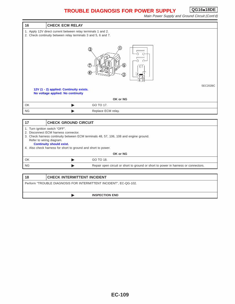
16 CHECK ECM RELAY
1. Apply 12V direct current between relay terminals 1 and 2.2. Check continuity between relay terminals 3 and 5, 6 and 7.
SEC202BC12V (1 - 2) applied: Continuity exists.No voltage applied: No continuity
OK or NG
OK © GO TO 17.
NG © Replace ECM relay.
17 CHECK GROUND CIRCUIT
1. Turn ignition switch “OFF”.2. Disconnect ECM harness connector.3. Check harness continuity between ECM terminals 48, 57, 106, 108 and engine ground.
Refer to wiring diagram.Continuity should exist.
4. Also check harness for short to ground and short to power.
OK or NG
OK © GO TO 18.
NG © Repair open circuit or short to ground or short to power in harness or connectors.
18 CHECK INTERMITTENT INCIDENT
Perform “TROUBLE DIAGNOSIS FOR INTERMITTENT INCIDENT”, EC-QG-102.
© INSPECTION END
TROUBLE DIAGNOSIS FOR POWER SUPPLY QG16I18DEMain Power Supply and Ground Circuit (Cont’d)
EC-109
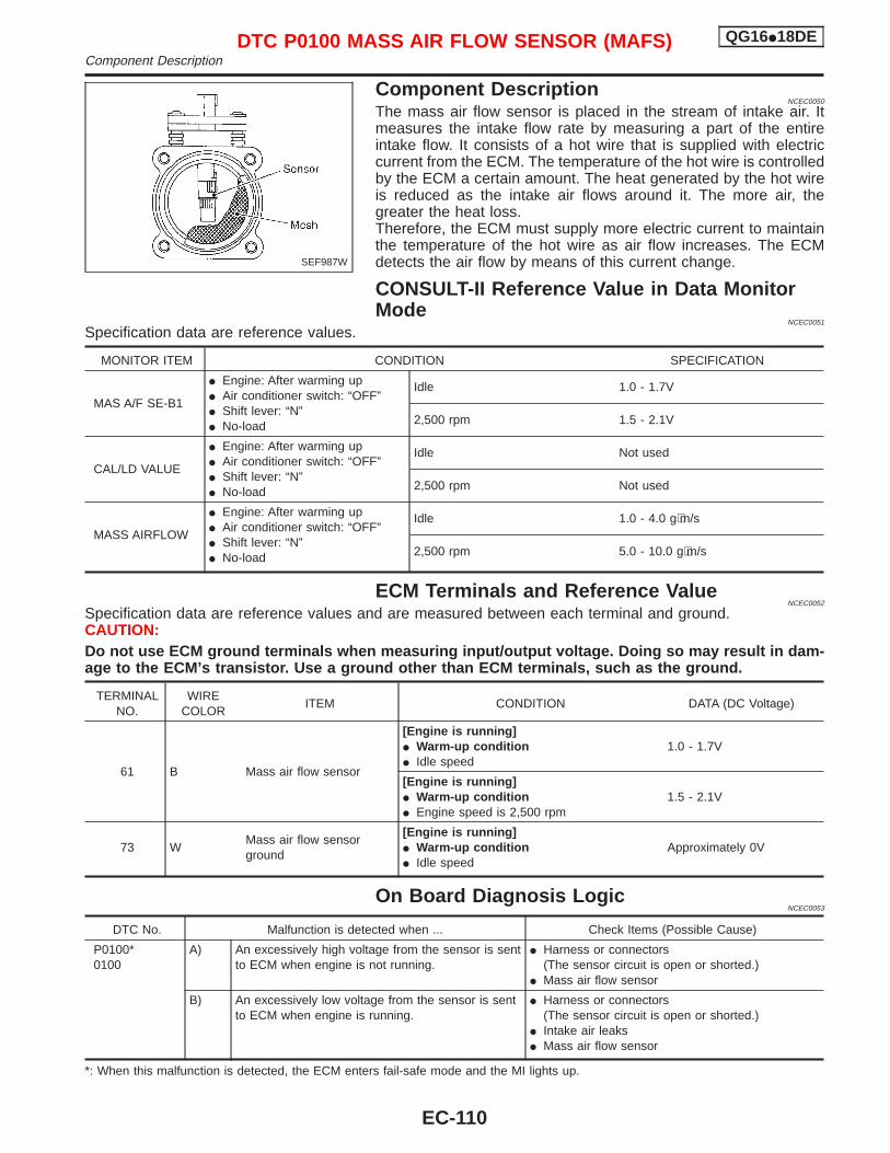
Component DescriptionNCEC0050
The mass air flow sensor is placed in the stream of intake air. Itmeasures the intake flow rate by measuring a part of the entireintake flow. It consists of a hot wire that is supplied with electriccurrent from the ECM. The temperature of the hot wire is controlledby the ECM a certain amount. The heat generated by the hot wireis reduced as the intake air flows around it. The more air, thegreater the heat loss.Therefore, the ECM must supply more electric current to maintainthe temperature of the hot wire as air flow increases. The ECMdetects the air flow by means of this current change.
CONSULT-II Reference Value in Data MonitorMode
NCEC0051
Specification data are reference values.
MONITOR ITEM CONDITION SPECIFICATION
MAS A/F SE-B1
I Engine: After warming upI Air conditioner switch: “OFF”I Shift lever: “N”I No-load
Idle 1.0 - 1.7V
2,500 rpm 1.5 - 2.1V
CAL/LD VALUE
I Engine: After warming upI Air conditioner switch: “OFF”I Shift lever: “N”I No-load
Idle Not used
2,500 rpm Not used
MASS AIRFLOW
I Engine: After warming upI Air conditioner switch: “OFF”I Shift lever: “N”I No-load
Idle 1.0 - 4.0 g⋅m/s
2,500 rpm 5.0 - 10.0 g⋅m/s
ECM Terminals and Reference ValueNCEC0052
Specification data are reference values and are measured between each terminal and ground.CAUTION:Do not use ECM ground terminals when measuring input/output voltage. Doing so may result in dam-age to the ECM’s transistor. Use a ground other than ECM terminals, such as the ground.
TERMINALNO.
WIRECOLOR
ITEM CONDITION DATA (DC Voltage)
61 B Mass air flow sensor
[Engine is running]I Warm-up conditionI Idle speed
1.0 - 1.7V
[Engine is running]I Warm-up conditionI Engine speed is 2,500 rpm
1.5 - 2.1V
73 WMass air flow sensorground
[Engine is running]I Warm-up conditionI Idle speed
Approximately 0V
On Board Diagnosis LogicNCEC0053
DTC No. Malfunction is detected when ... Check Items (Possible Cause)
P0100*0100
A) An excessively high voltage from the sensor is sentto ECM when engine is not running.
I Harness or connectors(The sensor circuit is open or shorted.)
I Mass air flow sensor
B) An excessively low voltage from the sensor is sentto ECM when engine is running.
I Harness or connectors(The sensor circuit is open or shorted.)
I Intake air leaksI Mass air flow sensor
*: When this malfunction is detected, the ECM enters fail-safe mode and the MI lights up.
SEF987W
DTC P0100 MASS AIR FLOW SENSOR (MAFS) QG16I18DEComponent Description
EC-110
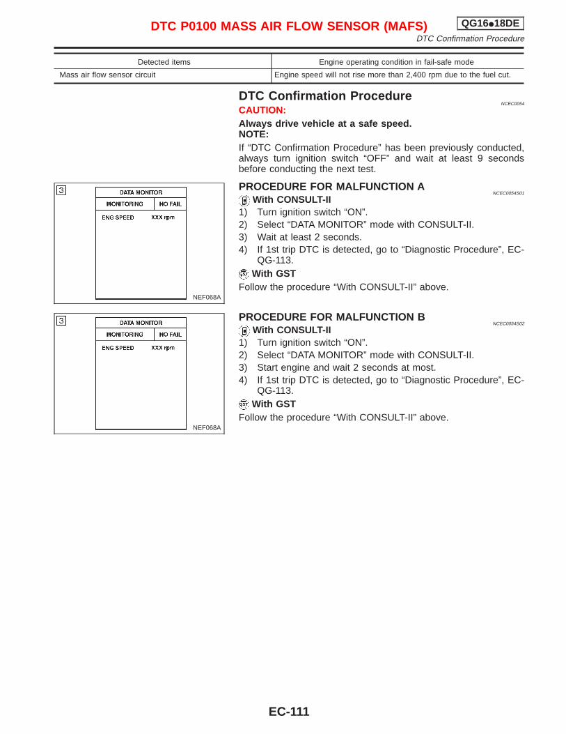
Detected items Engine operating condition in fail-safe mode
Mass air flow sensor circuit Engine speed will not rise more than 2,400 rpm due to the fuel cut.
DTC Confirmation ProcedureNCEC0054
CAUTION:Always drive vehicle at a safe speed.NOTE:If “DTC Confirmation Procedure” has been previously conducted,always turn ignition switch “OFF” and wait at least 9 secondsbefore conducting the next test.
PROCEDURE FOR MALFUNCTION ANCEC0054S01
With CONSULT-II1) Turn ignition switch “ON”.2) Select “DATA MONITOR” mode with CONSULT-II.3) Wait at least 2 seconds.4) If 1st trip DTC is detected, go to “Diagnostic Procedure”, EC-
QG-113.With GST
Follow the procedure “With CONSULT-II” above.
PROCEDURE FOR MALFUNCTION BNCEC0054S02
With CONSULT-II1) Turn ignition switch “ON”.2) Select “DATA MONITOR” mode with CONSULT-II.3) Start engine and wait 2 seconds at most.4) If 1st trip DTC is detected, go to “Diagnostic Procedure”, EC-
QG-113.With GST
Follow the procedure “With CONSULT-II” above.
NEF068A
NEF068A
DTC P0100 MASS AIR FLOW SENSOR (MAFS) QG16I18DEDTC Confirmation Procedure
EC-111
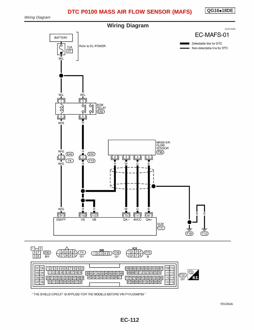
Wiring DiagramNCEC0056
YEC063A
DTC P0100 MASS AIR FLOW SENSOR (MAFS) QG16I18DEWiring Diagram
EC-112
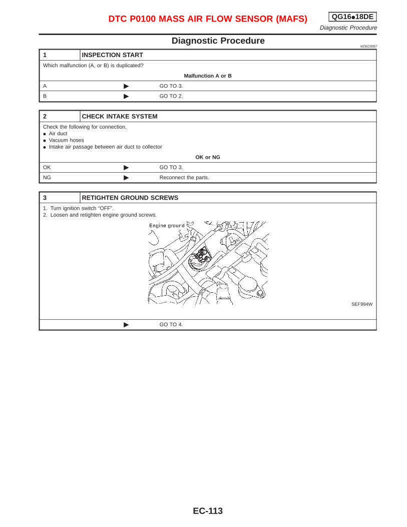
Diagnostic ProcedureNCEC0057
1 INSPECTION START
Which malfunction (A, or B) is duplicated?
Malfunction A or B
A © GO TO 3.
B © GO TO 2.
2 CHECK INTAKE SYSTEM
Check the following for connection.I Air ductI Vacuum hosesI Intake air passage between air duct to collector
OK or NG
OK © GO TO 3.
NG © Reconnect the parts.
3 RETIGHTEN GROUND SCREWS
1. Turn ignition switch “OFF”.2. Loosen and retighten engine ground screws.
SEF994W
© GO TO 4.
DTC P0100 MASS AIR FLOW SENSOR (MAFS) QG16I18DEDiagnostic Procedure
EC-113
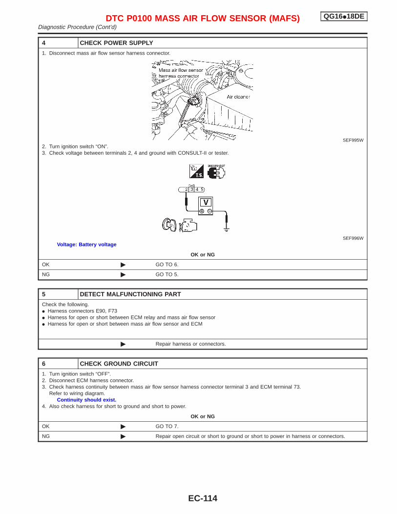
4 CHECK POWER SUPPLY
1. Disconnect mass air flow sensor harness connector.
SEF995W2. Turn ignition switch “ON”.3. Check voltage between terminals 2, 4 and ground with CONSULT-II or tester.
SEF996WVoltage: Battery voltage
OK or NG
OK © GO TO 6.
NG © GO TO 5.
5 DETECT MALFUNCTIONING PART
Check the following.I Harness connectors E90, F73I Harness for open or short between ECM relay and mass air flow sensorI Harness for open or short between mass air flow sensor and ECM
© Repair harness or connectors.
6 CHECK GROUND CIRCUIT
1. Turn ignition switch “OFF”.2. Disconnect ECM harness connector.3. Check harness continuity between mass air flow sensor harness connector terminal 3 and ECM terminal 73.
Refer to wiring diagram.Continuity should exist.
4. Also check harness for short to ground and short to power.
OK or NG
OK © GO TO 7.
NG © Repair open circuit or short to ground or short to power in harness or connectors.
DTC P0100 MASS AIR FLOW SENSOR (MAFS) QG16I18DEDiagnostic Procedure (Cont’d)
EC-114
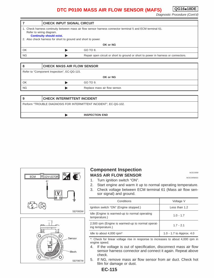
7 CHECK INPUT SIGNAL CIRCUIT
1. Check harness continuity between mass air flow sensor harness connector terminal 5 and ECM terminal 61.Refer to wiring diagram.
Continuity should exist.2. Also check harness for short to ground and short to power.
OK or NG
OK © GO TO 8.
NG © Repair open circuit or short to ground or short to power in harness or connectors.
8 CHECK MASS AIR FLOW SENSOR
Refer to “Component Inspection”, EC-QG-115.
OK or NG
OK © GO TO 9.
NG © Replace mass air flow sensor.
9 CHECK INTERMITTENT INCIDENT
Perform “TROUBLE DIAGNOSIS FOR INTERMITTENT INCIDENT”, EC-QG-102.
© INSPECTION END
Component InspectionNCEC0058
MASS AIR FLOW SENSORNCEC0058S01
1. Turn ignition switch “ON”.2. Start engine and warm it up to normal operating temperature.3. Check voltage between ECM terminal 61 (Mass air flow sen-
sor signal) and ground.
Conditions Voltage V
Ignition switch “ON” (Engine stopped.) Less than 1.2
Idle (Engine is warmed-up to normal operatingtemperature.)
1.0 - 1.7
2,500 rpm (Engine is warmed-up to normal operat-ing temperature.)
1.7 - 2.1
Idle to about 4,000 rpm* 1.0 - 1.7 to Approx. 4.0
*: Check for linear voltage rise in response to increases to about 4,000 rpm inengine speed.
4. If the voltage is out of specification, disconnect mass air flowsensor harness connector and connect it again. Repeat abovecheck.
5. If NG, remove mass air flow sensor from air duct. Check hotfilm for damage or dust.
SEF993W
SEF987W
DTC P0100 MASS AIR FLOW SENSOR (MAFS) QG16I18DEDiagnostic Procedure (Cont’d)
EC-115
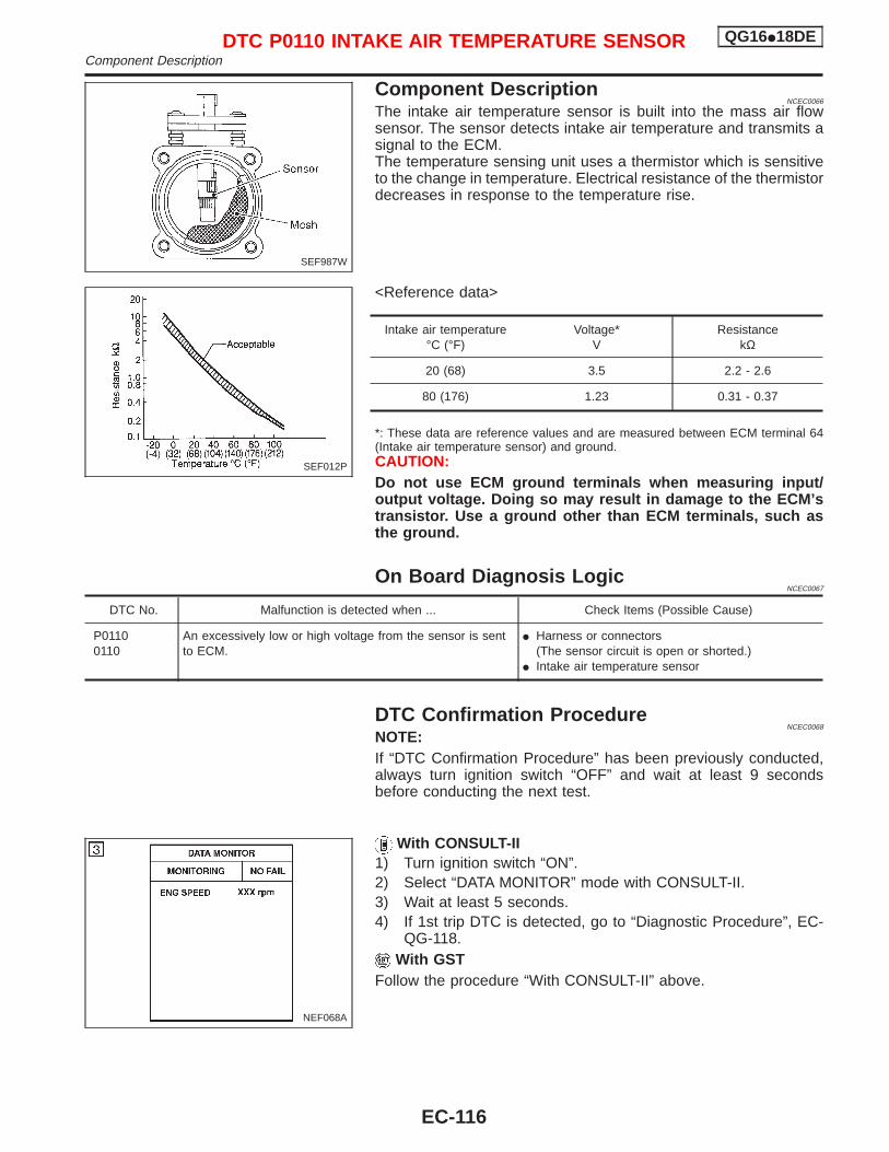
Component DescriptionNCEC0066
The intake air temperature sensor is built into the mass air flowsensor. The sensor detects intake air temperature and transmits asignal to the ECM.The temperature sensing unit uses a thermistor which is sensitiveto the change in temperature. Electrical resistance of the thermistordecreases in response to the temperature rise.
<Reference data>
Intake air temperature°C (°F)
Voltage*V
ResistancekΩ
20 (68) 3.5 2.2 - 2.6
80 (176) 1.23 0.31 - 0.37
*: These data are reference values and are measured between ECM terminal 64(Intake air temperature sensor) and ground.CAUTION:Do not use ECM ground terminals when measuring input/output voltage. Doing so may result in damage to the ECM’stransistor. Use a ground other than ECM terminals, such asthe ground.
On Board Diagnosis LogicNCEC0067
DTC No. Malfunction is detected when ... Check Items (Possible Cause)
P01100110
An excessively low or high voltage from the sensor is sentto ECM.
I Harness or connectors(The sensor circuit is open or shorted.)
I Intake air temperature sensor
DTC Confirmation ProcedureNCEC0068
NOTE:If “DTC Confirmation Procedure” has been previously conducted,always turn ignition switch “OFF” and wait at least 9 secondsbefore conducting the next test.
With CONSULT-II1) Turn ignition switch “ON”.2) Select “DATA MONITOR” mode with CONSULT-II.3) Wait at least 5 seconds.4) If 1st trip DTC is detected, go to “Diagnostic Procedure”, EC-
QG-118.With GST
Follow the procedure “With CONSULT-II” above.
SEF987W
SEF012P
NEF068A
DTC P0110 INTAKE AIR TEMPERATURE SENSOR QG16I18DEComponent Description
EC-116
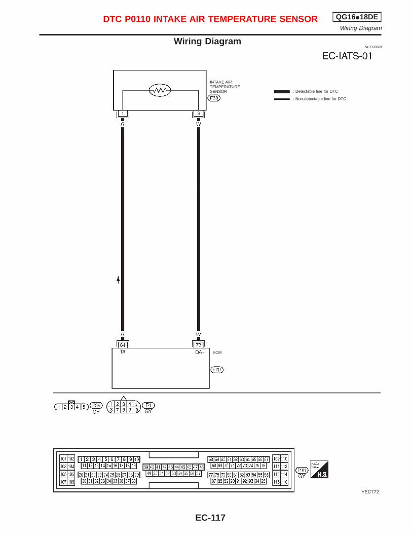
Wiring DiagramNCEC0069
YEC772
INTAKE AIRTEMPERATURESENSOR : Detectable line for DTC
: Non-detectable line for DTC
ECM
DTC P0110 INTAKE AIR TEMPERATURE SENSOR QG16I18DEWiring Diagram
EC-117
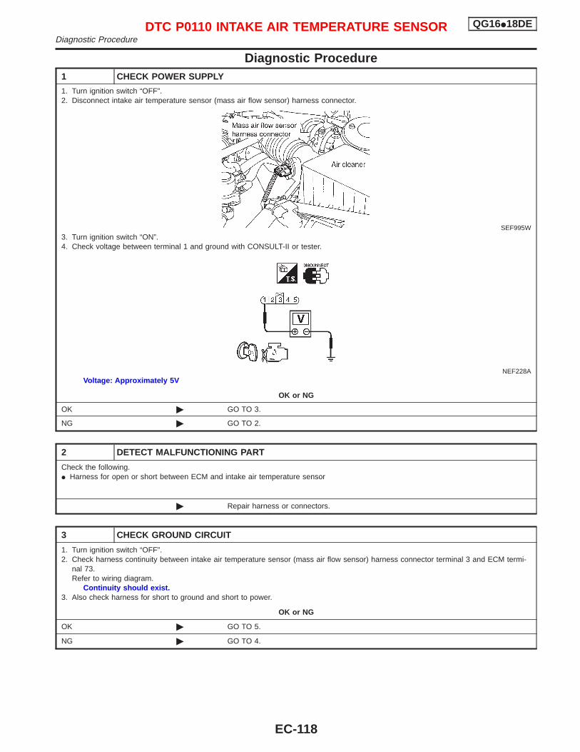
Diagnostic Procedure1 CHECK POWER SUPPLY
1. Turn ignition switch “OFF”.2. Disconnect intake air temperature sensor (mass air flow sensor) harness connector.
SEF995W3. Turn ignition switch “ON”.4. Check voltage between terminal 1 and ground with CONSULT-II or tester.
NEF228AVoltage: Approximately 5V
OK or NG
OK © GO TO 3.
NG © GO TO 2.
2 DETECT MALFUNCTIONING PART
Check the following.I Harness for open or short between ECM and intake air temperature sensor
© Repair harness or connectors.
3 CHECK GROUND CIRCUIT
1. Turn ignition switch “OFF”.2. Check harness continuity between intake air temperature sensor (mass air flow sensor) harness connector terminal 3 and ECM termi-
nal 73.Refer to wiring diagram.
Continuity should exist.3. Also check harness for short to ground and short to power.
OK or NG
OK © GO TO 5.
NG © GO TO 4.
DTC P0110 INTAKE AIR TEMPERATURE SENSOR QG16I18DEDiagnostic Procedure
EC-118
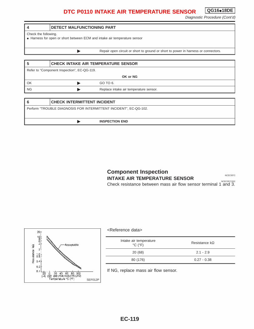
4 DETECT MALFUNCTIONING PART
Check the following.I Harness for open or short between ECM and intake air temperature sensor
© Repair open circuit or short to ground or short to power in harness or connectors.
5 CHECK INTAKE AIR TEMPERATURE SENSOR
Refer to “Component Inspection”, EC-QG-119.
OK or NG
OK © GO TO 6.
NG © Replace intake air temperature sensor.
6 CHECK INTERMITTENT INCIDENT
Perform “TROUBLE DIAGNOSIS FOR INTERMITTENT INCIDENT”, EC-QG-102.
© INSPECTION END
Component InspectionNCEC0071
INTAKE AIR TEMPERATURE SENSORNCEC0071S01
Check resistance between mass air flow sensor terminal 1 and 3.
<Reference data>
Intake air temperature°C (°F)
Resistance kΩ
20 (68) 2.1 - 2.9
80 (176) 0.27 - 0.38
If NG, replace mass air flow sensor.
SEF012P
DTC P0110 INTAKE AIR TEMPERATURE SENSOR QG16I18DEDiagnostic Procedure (Cont’d)
EC-119
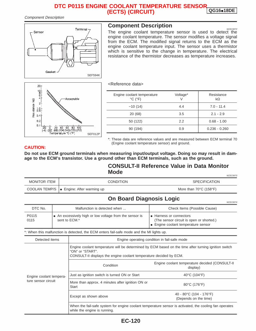
Component DescriptionNCEC0072
The engine coolant temperature sensor is used to detect theengine coolant temperature. The sensor modifies a voltage signalfrom the ECM. The modified signal returns to the ECM as theengine coolant temperature input. The sensor uses a thermistorwhich is sensitive to the change in temperature. The electricalresistance of the thermistor decreases as temperature increases.
<Reference data>
Engine coolant temperature°C (°F)
Voltage*V
ResistancekΩ
−10 (14) 4.4 7.0 - 11.4
20 (68) 3.5 2.1 - 2.9
50 (122) 2.2 0.68 - 1.00
90 (194) 0.9 0.236 - 0.260
*: These data are reference values and are measured between ECM terminal 70(Engine coolant temperature sensor) and ground.
CAUTION:Do not use ECM ground terminals when measuring input/output voltage. Doing so may result in dam-age to the ECM’s transistor. Use a ground other than ECM terminals, such as the ground.
CONSULT-II Reference Value in Data MonitorMode
NCEC0073
MONITOR ITEM CONDITION SPECIFICATION
COOLAN TEMP/S I Engine: After warming up More than 70°C (158°F)
On Board Diagnosis LogicNCEC0074
DTC No. Malfunction is detected when ... Check Items (Possible Cause)
P01150115
I An excessively high or low voltage from the sensor issent to ECM.*
I Harness or connectors(The sensor circuit is open or shorted.)
I Engine coolant temperature sensor
*: When this malfunction is detected, the ECM enters fail-safe mode and the MI lights up.
Detected items Engine operating condition in fail-safe mode
Engine coolant tempera-ture sensor circuit
Engine coolant temperature will be determined by ECM based on the time after turning ignition switch“ON” or “START”.CONSULT-II displays the engine coolant temperature decided by ECM.
ConditionEngine coolant temperature decided (CONSULT-II
display)
Just as ignition switch is turned ON or Start 40°C (104°F)
More than approx. 4 minutes after ignition ON orStart
80°C (176°F)
Except as shown above40 - 80°C (104 - 176°F)(Depends on the time)
When the fail-safe system for engine coolant temperature sensor is activated, the cooling fan operateswhile the engine is running.
SEF594K
SEF012P
DTC P0115 ENGINE COOLANT TEMPERATURE SENSOR(ECTS) (CIRCUIT) QG16I18DE
Component Description
EC-120
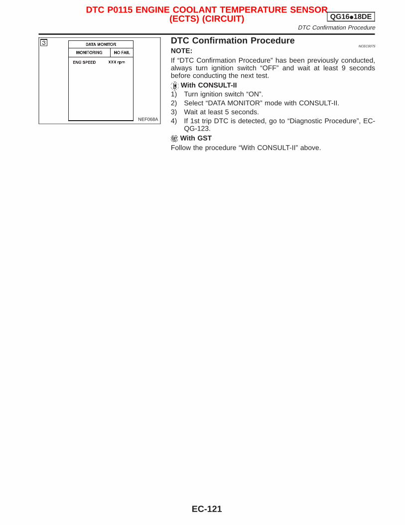
DTC Confirmation ProcedureNCEC0075
NOTE:If “DTC Confirmation Procedure” has been previously conducted,always turn ignition switch “OFF” and wait at least 9 secondsbefore conducting the next test.
With CONSULT-II1) Turn ignition switch “ON”.2) Select “DATA MONITOR” mode with CONSULT-II.3) Wait at least 5 seconds.4) If 1st trip DTC is detected, go to “Diagnostic Procedure”, EC-
QG-123.With GST
Follow the procedure “With CONSULT-II” above.
NEF068A
DTC P0115 ENGINE COOLANT TEMPERATURE SENSOR(ECTS) (CIRCUIT) QG16I18DE
DTC Confirmation Procedure
EC-121
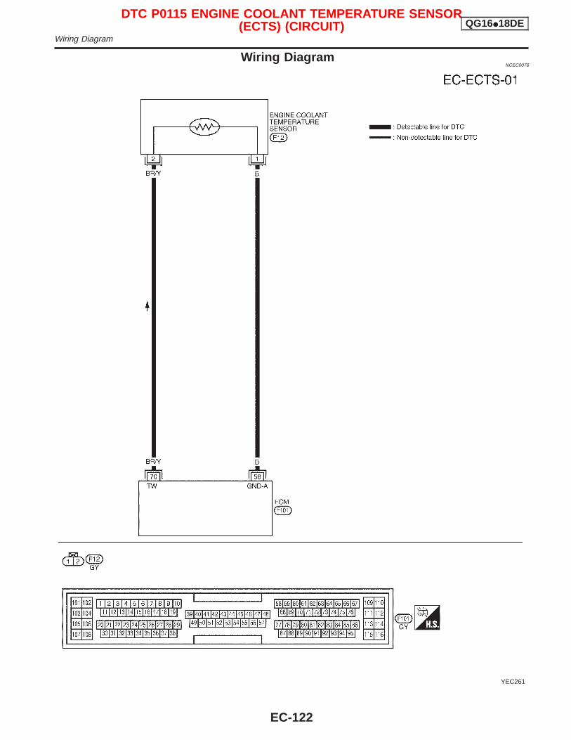
Wiring DiagramNCEC0076
YEC261
DTC P0115 ENGINE COOLANT TEMPERATURE SENSOR(ECTS) (CIRCUIT) QG16I18DE
Wiring Diagram
EC-122
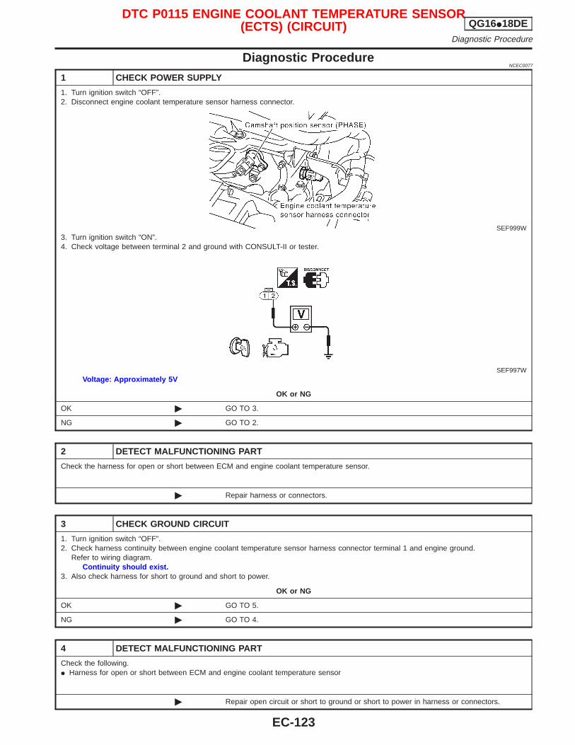
Diagnostic ProcedureNCEC0077
1 CHECK POWER SUPPLY
1. Turn ignition switch “OFF”.2. Disconnect engine coolant temperature sensor harness connector.
SEF999W3. Turn ignition switch “ON”.4. Check voltage between terminal 2 and ground with CONSULT-II or tester.
SEF997WVoltage: Approximately 5V
OK or NG
OK © GO TO 3.
NG © GO TO 2.
2 DETECT MALFUNCTIONING PART
Check the harness for open or short between ECM and engine coolant temperature sensor.
© Repair harness or connectors.
3 CHECK GROUND CIRCUIT
1. Turn ignition switch “OFF”.2. Check harness continuity between engine coolant temperature sensor harness connector terminal 1 and engine ground.
Refer to wiring diagram.Continuity should exist.
3. Also check harness for short to ground and short to power.
OK or NG
OK © GO TO 5.
NG © GO TO 4.
4 DETECT MALFUNCTIONING PART
Check the following.I Harness for open or short between ECM and engine coolant temperature sensor
© Repair open circuit or short to ground or short to power in harness or connectors.
DTC P0115 ENGINE COOLANT TEMPERATURE SENSOR(ECTS) (CIRCUIT) QG16I18DE
Diagnostic Procedure
EC-123
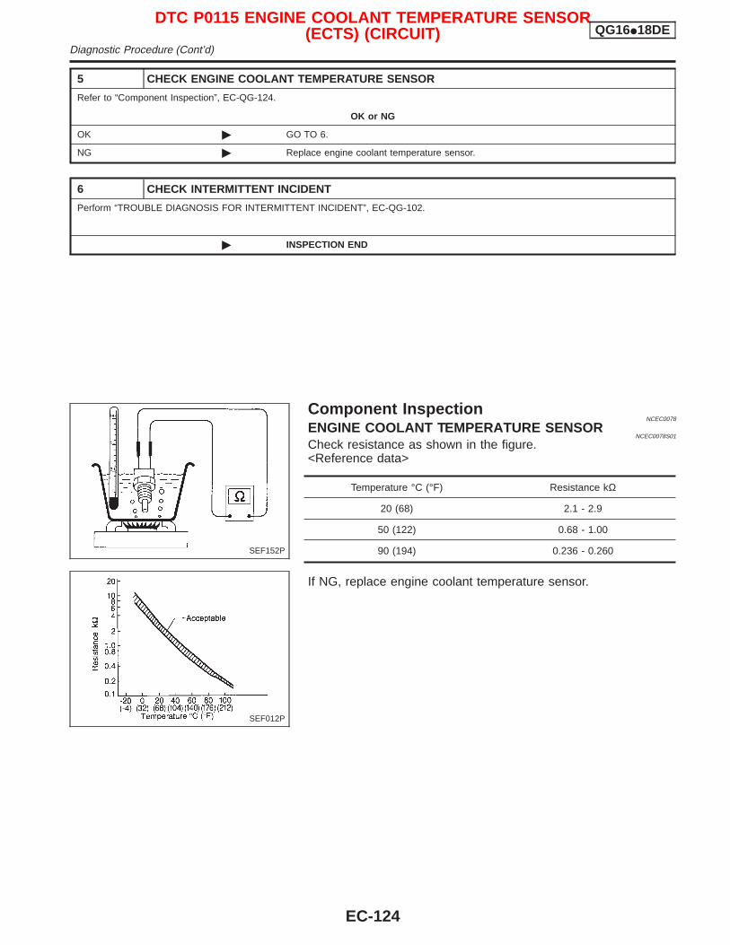
5 CHECK ENGINE COOLANT TEMPERATURE SENSOR
Refer to “Component Inspection”, EC-QG-124.
OK or NG
OK © GO TO 6.
NG © Replace engine coolant temperature sensor.
6 CHECK INTERMITTENT INCIDENT
Perform “TROUBLE DIAGNOSIS FOR INTERMITTENT INCIDENT”, EC-QG-102.
© INSPECTION END
Component InspectionNCEC0078
ENGINE COOLANT TEMPERATURE SENSORNCEC0078S01
Check resistance as shown in the figure.<Reference data>
Temperature °C (°F) Resistance kΩ
20 (68) 2.1 - 2.9
50 (122) 0.68 - 1.00
90 (194) 0.236 - 0.260
If NG, replace engine coolant temperature sensor.
SEF152P
SEF012P
DTC P0115 ENGINE COOLANT TEMPERATURE SENSOR(ECTS) (CIRCUIT) QG16I18DE
Diagnostic Procedure (Cont’d)
EC-124
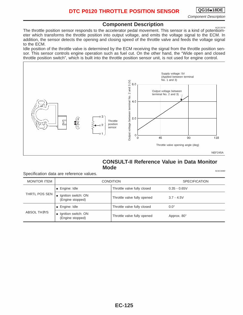
Component DescriptionNCEC0079
The throttle position sensor responds to the accelerator pedal movement. This sensor is a kind of potentiom-eter which transforms the throttle position into output voltage, and emits the voltage signal to the ECM. Inaddition, the sensor detects the opening and closing speed of the throttle valve and feeds the voltage signalto the ECM.Idle position of the throttle valve is determined by the ECM receiving the signal from the throttle position sen-sor. This sensor controls engine operation such as fuel cut. On the other hand, the “Wide open and closedthrottle position switch”, which is built into the throttle position sensor unit, is not used for engine control.
CONSULT-II Reference Value in Data MonitorMode
NCEC0080
Specification data are reference values.
MONITOR ITEM CONDITION SPECIFICATION
THRTL POS SEN
I Engine: Idle Throttle valve fully closed 0.35 - 0.65V
I Ignition switch: ON(Engine stopped)
Throttle valve fully opened 3.7 - 4.5V
ABSOL TH⋅P/S
I Engine: Idle Throttle valve fully closed 0.0°
I Ignition switch: ON(Engine stopped)
Throttle valve fully opened Approx. 80°
NEF245A
Throttlepositionsensor
Out
put
volta
gebe
twee
nte
rmin
alN
o.2
and
3(V
)
Throttle valve opening angle (deg)
Output voltage betweenterminal No. 2 and 3)
Supply voltage: 5V(Applied between terminalNo. 1 and 3)
DTC P0120 THROTTLE POSITION SENSOR QG16I18DEComponent Description
EC-125
ECM Terminals and Reference Value=NCEC0081
Specification data are reference values and are measured between each terminal and ground.CAUTION:Do not use ECM ground terminals when measuring input/output voltage. Doing so may result in dam-age to the ECM’s transistor. Use a ground other than ECM terminals, such as the ground.
TERMI-NALNO.
WIRECOLOR
ITEM CONDITION DATA (DC Voltage)
58 B Sensors’ ground[Engine is running]I Warm up conditionI Idle speed
Approximately 0V
92 Y Throttle position sensor
[Engine is running]I Accelerator pedal fully released
0.35 - 0.65V
[Ignition switch “ON”]I Accelerator pedal fully depressed
3.7 - 4.5V
111 G Sensors’ power supply [Ignition switch “ON”] Approximately 5V
On Board Diagnosis LogicNCEC0082
DTC No. Malfunction is detected when ... Check Items (Possible Cause)
P0120*0120
An excessively low or high voltage from the sensor issent to ECM while driving.
I Harness or connectors(The throttle position sensor circuit is open orshorted.)
I Throttle position sensor
*: When this malfunction is detected, the ECM enters fail-safe mode and the MI lights up.
Detected items Engine operating condition in fail-safe mode
Throttle position sensorcircuit
Throttle position will be determined based on the injected fuel amount and the engine speed.Therefore, acceleration will be poor.
Condition Driving condition
When engine is idling Normal
When accelerating Poor acceleration
DTC Confirmation ProcedureNCEC0083
NOTE:If “DTC Confirmation Procedure” has been previously conducted,always turn ignition switch “OFF” and wait at least 9 secondsbefore conducting the next test.CAUTION:Always drive vehicle at a safe speed.TESTING CONDITION:I Before performing the following procedure, confirm that
battery voltage is more than 10V at idle.I This test may be conducted with the drive wheels lifted in
the shop or by driving the vehicle. If a road test isexpected to be easier, it is unnecessary to lift the vehicle.
DTC P0120 THROTTLE POSITION SENSOR QG16I18DEECM Terminals and Reference Value
EC-126
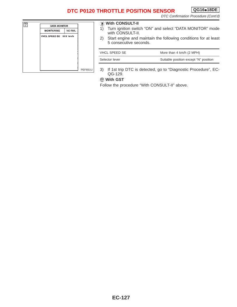
With CONSULT-II1) Turn ignition switch “ON” and select “DATA MONITOR” mode
with CONSULT-II.2) Start engine and maintain the following conditions for at least
5 consecutive seconds.
VHCL SPEED SE More than 4 km/h (2 MPH)
Selector lever Suitable position except “N” position
3) If 1st trip DTC is detected, go to “Diagnostic Procedure”, EC-QG-129.
With GSTFollow the procedure “With CONSULT-II” above.
PEF651U
DTC P0120 THROTTLE POSITION SENSOR QG16I18DEDTC Confirmation Procedure (Cont’d)
EC-127
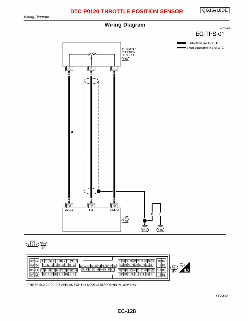
Wiring DiagramNCEC0084
YEC064A
DTC P0120 THROTTLE POSITION SENSOR QG16I18DEWiring Diagram
EC-128
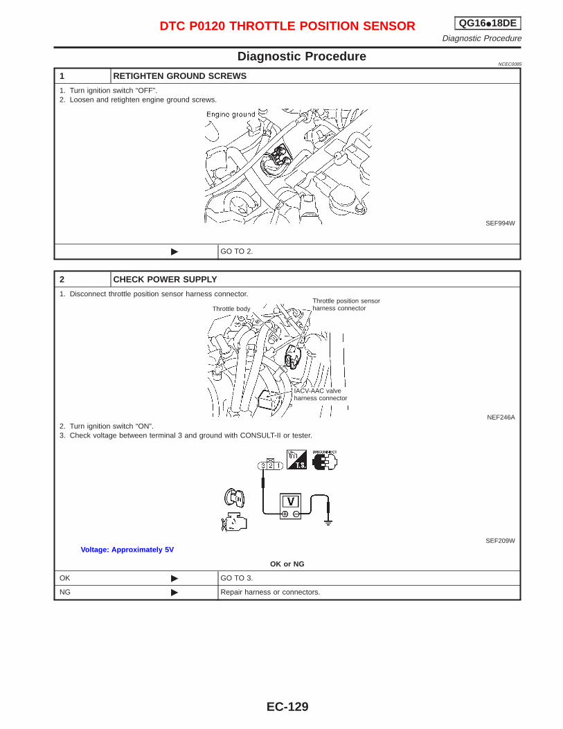
Diagnostic ProcedureNCEC0085
1 RETIGHTEN GROUND SCREWS
1. Turn ignition switch “OFF”.2. Loosen and retighten engine ground screws.
SEF994W
© GO TO 2.
2 CHECK POWER SUPPLY
1. Disconnect throttle position sensor harness connector.
NEF246A2. Turn ignition switch “ON”.3. Check voltage between terminal 3 and ground with CONSULT-II or tester.
SEF209WVoltage: Approximately 5V
OK or NG
OK © GO TO 3.
NG © Repair harness or connectors.
Throttle bodyThrottle position sensorharness connector
IACV-AAC valveharness connector
DTC P0120 THROTTLE POSITION SENSOR QG16I18DEDiagnostic Procedure
EC-129
3 CHECK GROUND CIRCUIT
1. Turn ignition switch “OFF”.2. Check harness continuity between throttle position sensor harness connector terminal 1 and engine ground.
Refer to wiring diagram.Continuity should exist.
3. Also check harness for short to ground and short to power.
OK or NG
OK © GO TO 5.
NG © GO TO 4.
4 DETECT MALFUNCTIONING PART
Check the harness for open or short between ECM and throttle position sensor.
© Repair open circuit or short to ground or short to power in harness or connectors.
5 CHECK INPUT SIGNAL CIRCUIT
1. Disconnect ECM harness connector.2. Check harness continuity between ECM terminal 92 and throttle position sensor harness connector terminal 2.
Refer to wiring diagram.Continuity should exist.
3. Also check harness for short to ground and short to power.
OK or NG
OK © GO TO 6.
NG © Repair open circuit or short to ground or short to power in harness or connectors.
6 CHECK THROTTLE POSITION SENSOR
Refer to “Component Inspection”, EC-QG-131.
OK or NG
OK © GO TO 7.
NG © Replace throttle position sensor. To adjust it, perform “Basic Inspection”, EC-QG-72.
7 CHECK INTERMITTENT INCIDENT
Perform “TROUBLE DIAGNOSIS FOR INTERMITTENT INCIDENT”, EC-QG-102.
© INSPECTION END
DTC P0120 THROTTLE POSITION SENSOR QG16I18DEDiagnostic Procedure (Cont’d)
EC-130
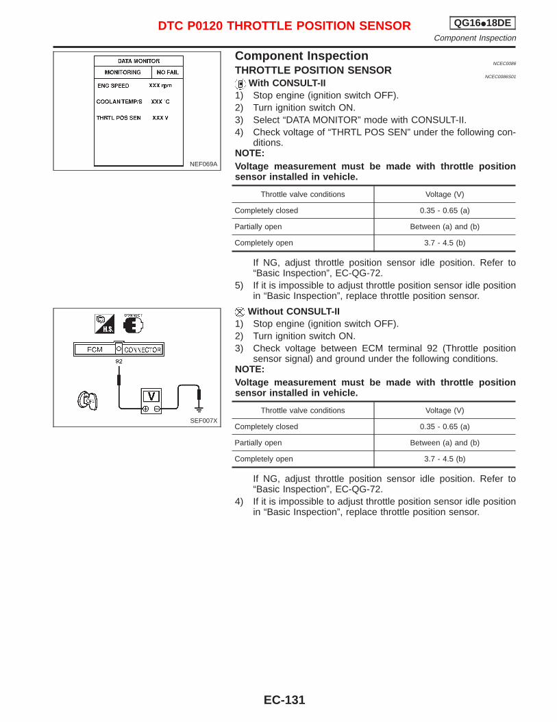
Component InspectionNCEC0086
THROTTLE POSITION SENSORNCEC0086S01
With CONSULT-II1) Stop engine (ignition switch OFF).2) Turn ignition switch ON.3) Select “DATA MONITOR” mode with CONSULT-II.4) Check voltage of “THRTL POS SEN” under the following con-
ditions.NOTE:Voltage measurement must be made with throttle positionsensor installed in vehicle.
Throttle valve conditions Voltage (V)
Completely closed 0.35 - 0.65 (a)
Partially open Between (a) and (b)
Completely open 3.7 - 4.5 (b)
If NG, adjust throttle position sensor idle position. Refer to“Basic Inspection”, EC-QG-72.
5) If it is impossible to adjust throttle position sensor idle positionin “Basic Inspection”, replace throttle position sensor.
Without CONSULT-II1) Stop engine (ignition switch OFF).2) Turn ignition switch ON.3) Check voltage between ECM terminal 92 (Throttle position
sensor signal) and ground under the following conditions.NOTE:Voltage measurement must be made with throttle positionsensor installed in vehicle.
Throttle valve conditions Voltage (V)
Completely closed 0.35 - 0.65 (a)
Partially open Between (a) and (b)
Completely open 3.7 - 4.5 (b)
If NG, adjust throttle position sensor idle position. Refer to“Basic Inspection”, EC-QG-72.
4) If it is impossible to adjust throttle position sensor idle positionin “Basic Inspection”, replace throttle position sensor.
NEF069A
SEF007X
DTC P0120 THROTTLE POSITION SENSOR QG16I18DEComponent Inspection
EC-131
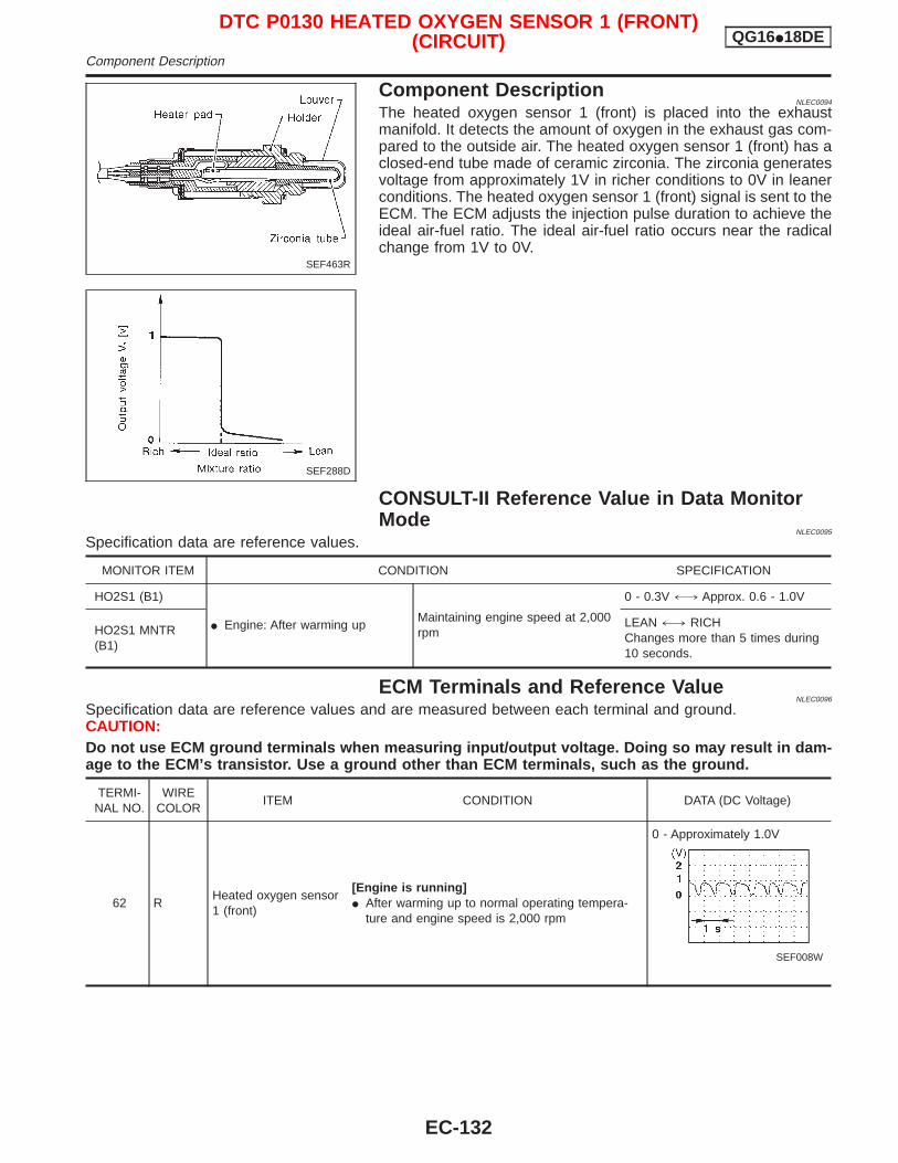
Component DescriptionNLEC0094
The heated oxygen sensor 1 (front) is placed into the exhaustmanifold. It detects the amount of oxygen in the exhaust gas com-pared to the outside air. The heated oxygen sensor 1 (front) has aclosed-end tube made of ceramic zirconia. The zirconia generatesvoltage from approximately 1V in richer conditions to 0V in leanerconditions. The heated oxygen sensor 1 (front) signal is sent to theECM. The ECM adjusts the injection pulse duration to achieve theideal air-fuel ratio. The ideal air-fuel ratio occurs near the radicalchange from 1V to 0V.
CONSULT-II Reference Value in Data MonitorMode
NLEC0095
Specification data are reference values.
MONITOR ITEM CONDITION SPECIFICATION
HO2S1 (B1)
I Engine: After warming upMaintaining engine speed at 2,000rpm
0 - 0.3V +, Approx. 0.6 - 1.0V
HO2S1 MNTR(B1)
LEAN +, RICHChanges more than 5 times during10 seconds.
ECM Terminals and Reference ValueNLEC0096
Specification data are reference values and are measured between each terminal and ground.CAUTION:Do not use ECM ground terminals when measuring input/output voltage. Doing so may result in dam-age to the ECM’s transistor. Use a ground other than ECM terminals, such as the ground.
TERMI-NAL NO.
WIRECOLOR
ITEM CONDITION DATA (DC Voltage)
62 RHeated oxygen sensor1 (front)
[Engine is running]I After warming up to normal operating tempera-
ture and engine speed is 2,000 rpm
0 - Approximately 1.0V
SEF008W
SEF463R
SEF288D
DTC P0130 HEATED OXYGEN SENSOR 1 (FRONT)(CIRCUIT) QG16I18DE
Component Description
EC-132
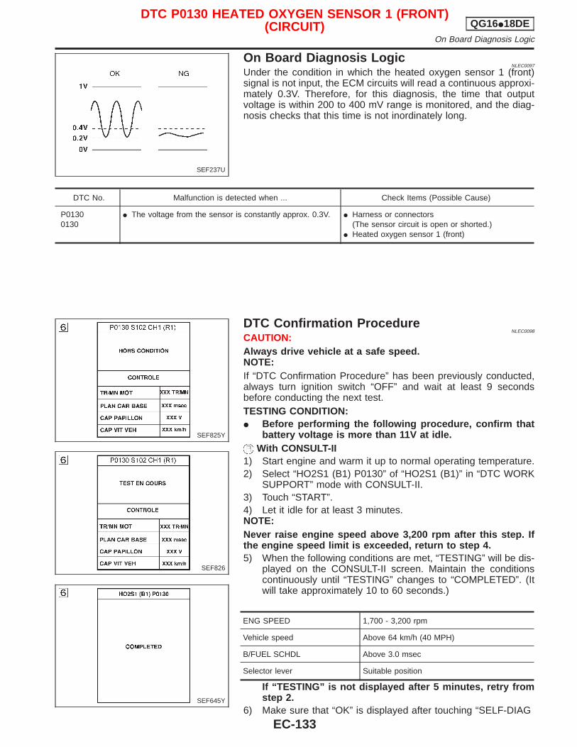
On Board Diagnosis LogicNLEC0097
Under the condition in which the heated oxygen sensor 1 (front)signal is not input, the ECM circuits will read a continuous approxi-mately 0.3V. Therefore, for this diagnosis, the time that outputvoltage is within 200 to 400 mV range is monitored, and the diag-nosis checks that this time is not inordinately long.
DTC No. Malfunction is detected when ... Check Items (Possible Cause)
P01300130
I The voltage from the sensor is constantly approx. 0.3V. I Harness or connectors(The sensor circuit is open or shorted.)
I Heated oxygen sensor 1 (front)
DTC Confirmation ProcedureNLEC0098
CAUTION:Always drive vehicle at a safe speed.NOTE:If “DTC Confirmation Procedure” has been previously conducted,always turn ignition switch “OFF” and wait at least 9 secondsbefore conducting the next test.TESTING CONDITION:I Before performing the following procedure, confirm that
battery voltage is more than 11V at idle.With CONSULT-II
1) Start engine and warm it up to normal operating temperature.2) Select “HO2S1 (B1) P0130” of “HO2S1 (B1)” in “DTC WORK
SUPPORT” mode with CONSULT-II.3) Touch “START”.4) Let it idle for at least 3 minutes.NOTE:Never raise engine speed above 3,200 rpm after this step. Ifthe engine speed limit is exceeded, return to step 4.5) When the following conditions are met, “TESTING” will be dis-
played on the CONSULT-II screen. Maintain the conditionscontinuously until “TESTING” changes to “COMPLETED”. (Itwill take approximately 10 to 60 seconds.)
ENG SPEED 1,700 - 3,200 rpm
Vehicle speed Above 64 km/h (40 MPH)
B/FUEL SCHDL Above 3.0 msec
Selector lever Suitable position
If “TESTING” is not displayed after 5 minutes, retry fromstep 2.
6) Make sure that “OK” is displayed after touching “SELF-DIAG
SEF237U
SEF825Y
SEF826
SEF645Y
DTC P0130 HEATED OXYGEN SENSOR 1 (FRONT)(CIRCUIT) QG16I18DE
On Board Diagnosis Logic
EC-133
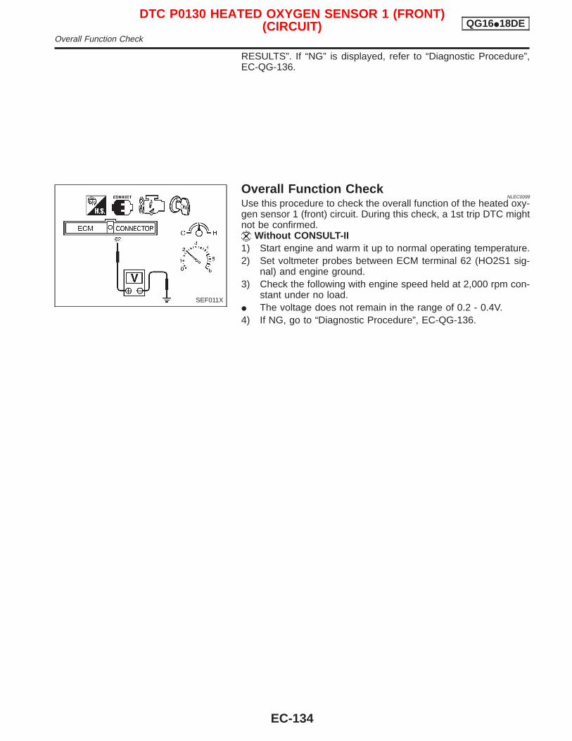
RESULTS”. If “NG” is displayed, refer to “Diagnostic Procedure”,EC-QG-136.
Overall Function CheckNLEC0099
Use this procedure to check the overall function of the heated oxy-gen sensor 1 (front) circuit. During this check, a 1st trip DTC mightnot be confirmed.
Without CONSULT-II1) Start engine and warm it up to normal operating temperature.2) Set voltmeter probes between ECM terminal 62 (HO2S1 sig-
nal) and engine ground.3) Check the following with engine speed held at 2,000 rpm con-
stant under no load.I The voltage does not remain in the range of 0.2 - 0.4V.4) If NG, go to “Diagnostic Procedure”, EC-QG-136.
SEF011X
DTC P0130 HEATED OXYGEN SENSOR 1 (FRONT)(CIRCUIT) QG16I18DE
Overall Function Check
EC-134
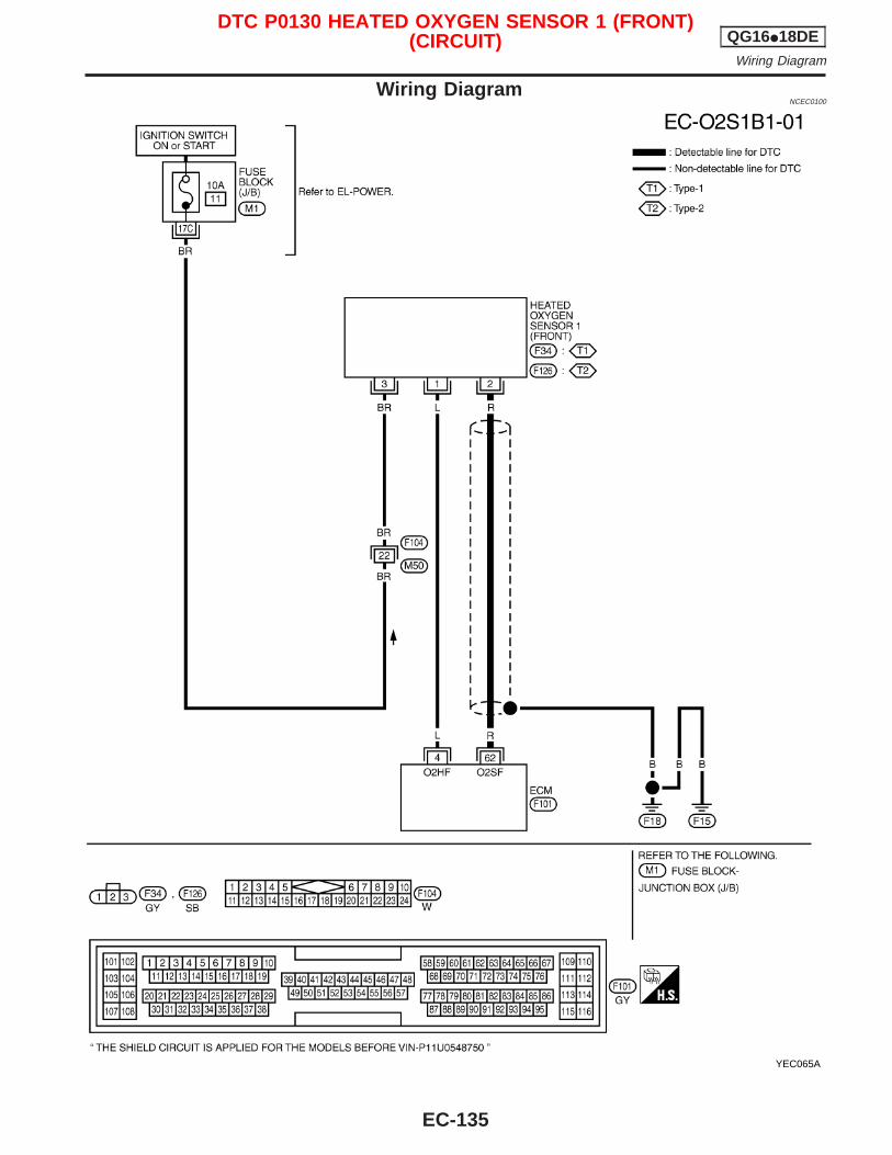
Wiring DiagramNCEC0100
YEC065A
DTC P0130 HEATED OXYGEN SENSOR 1 (FRONT)(CIRCUIT) QG16I18DE
Wiring Diagram
EC-135
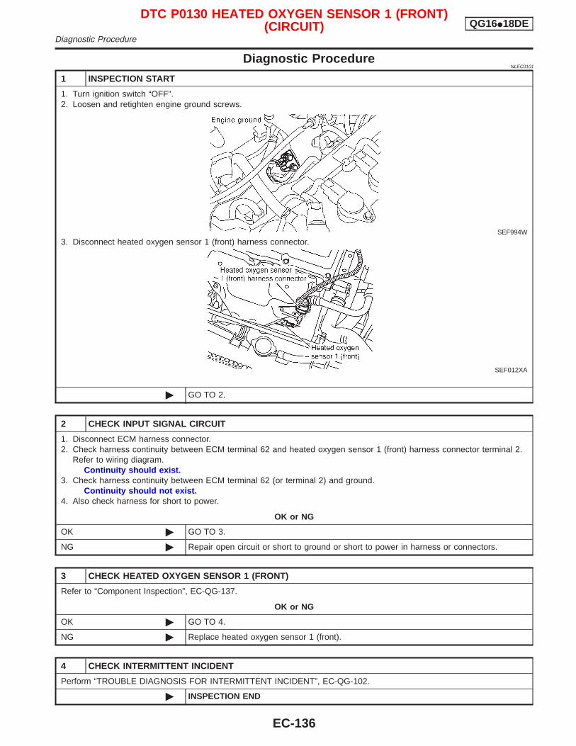
Diagnostic ProcedureNLEC0101
1 INSPECTION START
1. Turn ignition switch “OFF”.2. Loosen and retighten engine ground screws.
SEF994W
3. Disconnect heated oxygen sensor 1 (front) harness connector.
SEF012XA
© GO TO 2.
2 CHECK INPUT SIGNAL CIRCUIT
1. Disconnect ECM harness connector.2. Check harness continuity between ECM terminal 62 and heated oxygen sensor 1 (front) harness connector terminal 2.
Refer to wiring diagram.Continuity should exist.
3. Check harness continuity between ECM terminal 62 (or terminal 2) and ground.Continuity should not exist.
4. Also check harness for short to power.
OK or NG
OK © GO TO 3.
NG © Repair open circuit or short to ground or short to power in harness or connectors.
3 CHECK HEATED OXYGEN SENSOR 1 (FRONT)
Refer to “Component Inspection”, EC-QG-137.
OK or NG
OK © GO TO 4.
NG © Replace heated oxygen sensor 1 (front).
4 CHECK INTERMITTENT INCIDENT
Perform “TROUBLE DIAGNOSIS FOR INTERMITTENT INCIDENT”, EC-QG-102.
© INSPECTION END
DTC P0130 HEATED OXYGEN SENSOR 1 (FRONT)(CIRCUIT) QG16I18DE
Diagnostic Procedure
EC-136
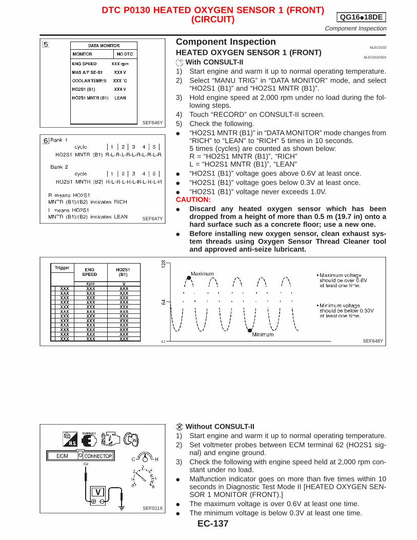
Component InspectionNLEC0102
HEATED OXYGEN SENSOR 1 (FRONT)NLEC0102S01
With CONSULT-II1) Start engine and warm it up to normal operating temperature.2) Select “MANU TRIG” in “DATA MONITOR” mode, and select
“HO2S1 (B1)” and “HO2S1 MNTR (B1)”.3) Hold engine speed at 2,000 rpm under no load during the fol-
lowing steps.4) Touch “RECORD” on CONSULT-II screen.5) Check the following.I “HO2S1 MNTR (B1)” in “DATA MONITOR” mode changes from
“RICH” to “LEAN” to “RICH” 5 times in 10 seconds.5 times (cycles) are counted as shown below:R = “HO2S1 MNTR (B1)”, “RICH”L = “HO2S1 MNTR (B1)”, “LEAN”
I “HO2S1 (B1)” voltage goes above 0.6V at least once.I “HO2S1 (B1)” voltage goes below 0.3V at least once.I “HO2S1 (B1)” voltage never exceeds 1.0V.CAUTION:I Discard any heated oxygen sensor which has been
dropped from a height of more than 0.5 m (19.7 in) onto ahard surface such as a concrete floor; use a new one.
I Before installing new oxygen sensor, clean exhaust sys-tem threads using Oxygen Sensor Thread Cleaner tooland approved anti-seize lubricant.
Without CONSULT-II1) Start engine and warm it up to normal operating temperature.2) Set voltmeter probes between ECM terminal 62 (HO2S1 sig-
nal) and engine ground.3) Check the following with engine speed held at 2,000 rpm con-
stant under no load.I Malfunction indicator goes on more than five times within 10
seconds in Diagnostic Test Mode II [HEATED OXYGEN SEN-SOR 1 MONITOR (FRONT).]
I The maximum voltage is over 0.6V at least one time.I The minimum voltage is below 0.3V at least one time.
SEF646Y
SEF647Y
SEF648Y
SEF011X
DTC P0130 HEATED OXYGEN SENSOR 1 (FRONT)(CIRCUIT) QG16I18DE
Component Inspection
EC-137

I The voltage never exceeds 1.0V.CAUTION:I Discard any heated oxygen sensor which has been
dropped from a height of more than 0.5 m (19.7 in) onto ahard surface such as a concrete floor; use a new one.
I Before installing new oxygen sensor, clean exhaust sys-tem threads using Oxygen Sensor Thread Cleaner tooland approved anti-seize lubricant.
DTC P0130 HEATED OXYGEN SENSOR 1 (FRONT)(CIRCUIT) QG16I18DE
Component Inspection (Cont’d)
EC-138
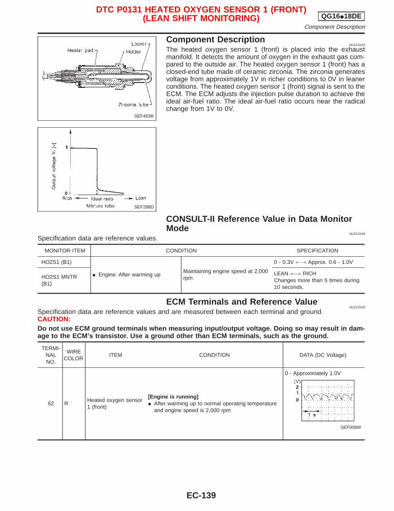
Component DescriptionNLEC0103
The heated oxygen sensor 1 (front) is placed into the exhaustmanifold. It detects the amount of oxygen in the exhaust gas com-pared to the outside air. The heated oxygen sensor 1 (front) has aclosed-end tube made of ceramic zirconia. The zirconia generatesvoltage from approximately 1V in richer conditions to 0V in leanerconditions. The heated oxygen sensor 1 (front) signal is sent to theECM. The ECM adjusts the injection pulse duration to achieve theideal air-fuel ratio. The ideal air-fuel ratio occurs near the radicalchange from 1V to 0V.
CONSULT-II Reference Value in Data MonitorMode
NLEC0104
Specification data are reference values.
MONITOR ITEM CONDITION SPECIFICATION
HO2S1 (B1)
I Engine: After warming upMaintaining engine speed at 2,000rpm
0 - 0.3V +, Approx. 0.6 - 1.0V
HO2S1 MNTR(B1)
LEAN +, RICHChanges more than 5 times during10 seconds.
ECM Terminals and Reference ValueNLEC0105
Specification data are reference values and are measured between each terminal and ground.CAUTION:Do not use ECM ground terminals when measuring input/output voltage. Doing so may result in dam-age to the ECM’s transistor. Use a ground other than ECM terminals, such as the ground.
TERMI-NALNO.
WIRECOLOR
ITEM CONDITION DATA (DC Voltage)
62 RHeated oxygen sensor1 (front)
[Engine is running]I After warming up to normal operating temperature
and engine speed is 2,000 rpm
0 - Approximately 1.0V
SEF008W
SEF463R
SEF288D
DTC P0131 HEATED OXYGEN SENSOR 1 (FRONT)(LEAN SHIFT MONITORING) QG16I18DE
Component Description
EC-139
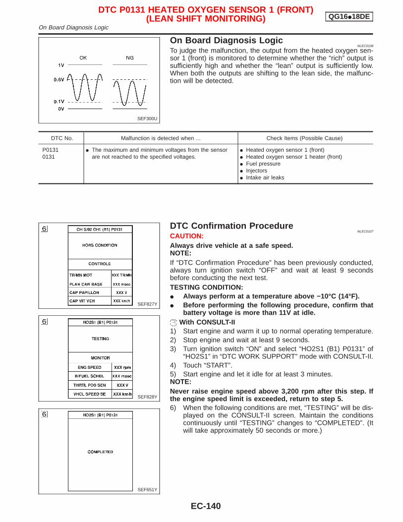
On Board Diagnosis LogicNLEC0106
To judge the malfunction, the output from the heated oxygen sen-sor 1 (front) is monitored to determine whether the “rich” output issufficiently high and whether the “lean” output is sufficiently low.When both the outputs are shifting to the lean side, the malfunc-tion will be detected.
DTC No. Malfunction is detected when ... Check Items (Possible Cause)
P01310131
I The maximum and minimum voltages from the sensorare not reached to the specified voltages.
I Heated oxygen sensor 1 (front)I Heated oxygen sensor 1 heater (front)I Fuel pressureI InjectorsI Intake air leaks
DTC Confirmation ProcedureNLEC0107
CAUTION:Always drive vehicle at a safe speed.NOTE:If “DTC Confirmation Procedure” has been previously conducted,always turn ignition switch “OFF” and wait at least 9 secondsbefore conducting the next test.TESTING CONDITION:I Always perform at a temperature above −10°C (14°F).I Before performing the following procedure, confirm that
battery voltage is more than 11V at idle.With CONSULT-II
1) Start engine and warm it up to normal operating temperature.2) Stop engine and wait at least 9 seconds.3) Turn ignition switch “ON” and select “HO2S1 (B1) P0131” of
“HO2S1” in “DTC WORK SUPPORT” mode with CONSULT-II.4) Touch “START”.5) Start engine and let it idle for at least 3 minutes.NOTE:Never raise engine speed above 3,200 rpm after this step. Ifthe engine speed limit is exceeded, return to step 5.6) When the following conditions are met, “TESTING” will be dis-
played on the CONSULT-II screen. Maintain the conditionscontinuously until “TESTING” changes to “COMPLETED”. (Itwill take approximately 50 seconds or more.)
SEF300U
SEF827Y
SEF828Y
SEF651Y
DTC P0131 HEATED OXYGEN SENSOR 1 (FRONT)(LEAN SHIFT MONITORING) QG16I18DE
On Board Diagnosis Logic
EC-140
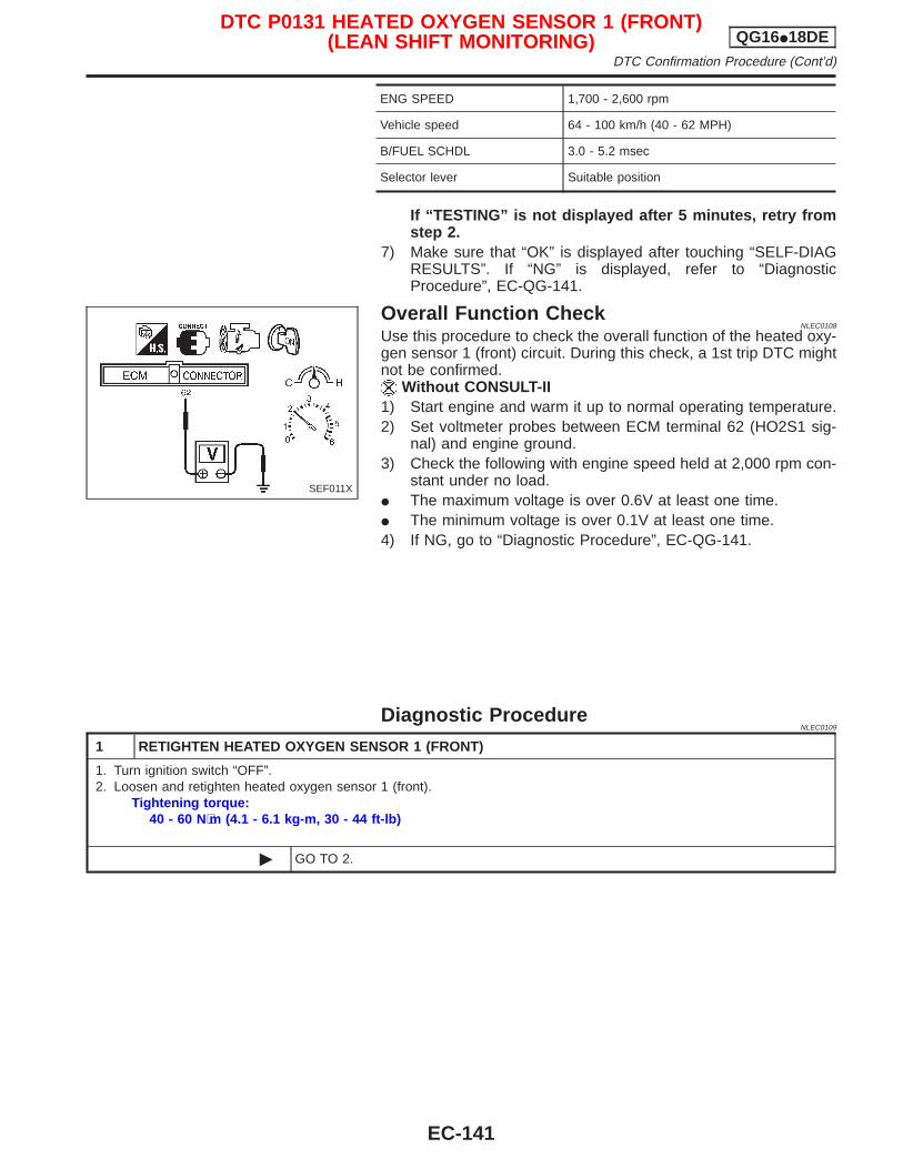
ENG SPEED 1,700 - 2,600 rpm
Vehicle speed 64 - 100 km/h (40 - 62 MPH)
B/FUEL SCHDL 3.0 - 5.2 msec
Selector lever Suitable position
If “TESTING” is not displayed after 5 minutes, retry fromstep 2.
7) Make sure that “OK” is displayed after touching “SELF-DIAGRESULTS”. If “NG” is displayed, refer to “DiagnosticProcedure”, EC-QG-141.
Overall Function CheckNLEC0108
Use this procedure to check the overall function of the heated oxy-gen sensor 1 (front) circuit. During this check, a 1st trip DTC mightnot be confirmed.
Without CONSULT-II1) Start engine and warm it up to normal operating temperature.2) Set voltmeter probes between ECM terminal 62 (HO2S1 sig-
nal) and engine ground.3) Check the following with engine speed held at 2,000 rpm con-
stant under no load.I The maximum voltage is over 0.6V at least one time.I The minimum voltage is over 0.1V at least one time.4) If NG, go to “Diagnostic Procedure”, EC-QG-141.
Diagnostic ProcedureNLEC0109
1 RETIGHTEN HEATED OXYGEN SENSOR 1 (FRONT)
1. Turn ignition switch “OFF”.2. Loosen and retighten heated oxygen sensor 1 (front).
Tightening torque:40 - 60 N⋅m (4.1 - 6.1 kg-m, 30 - 44 ft-lb)
© GO TO 2.
SEF011X
DTC P0131 HEATED OXYGEN SENSOR 1 (FRONT)(LEAN SHIFT MONITORING) QG16I18DE
DTC Confirmation Procedure (Cont’d)
EC-141
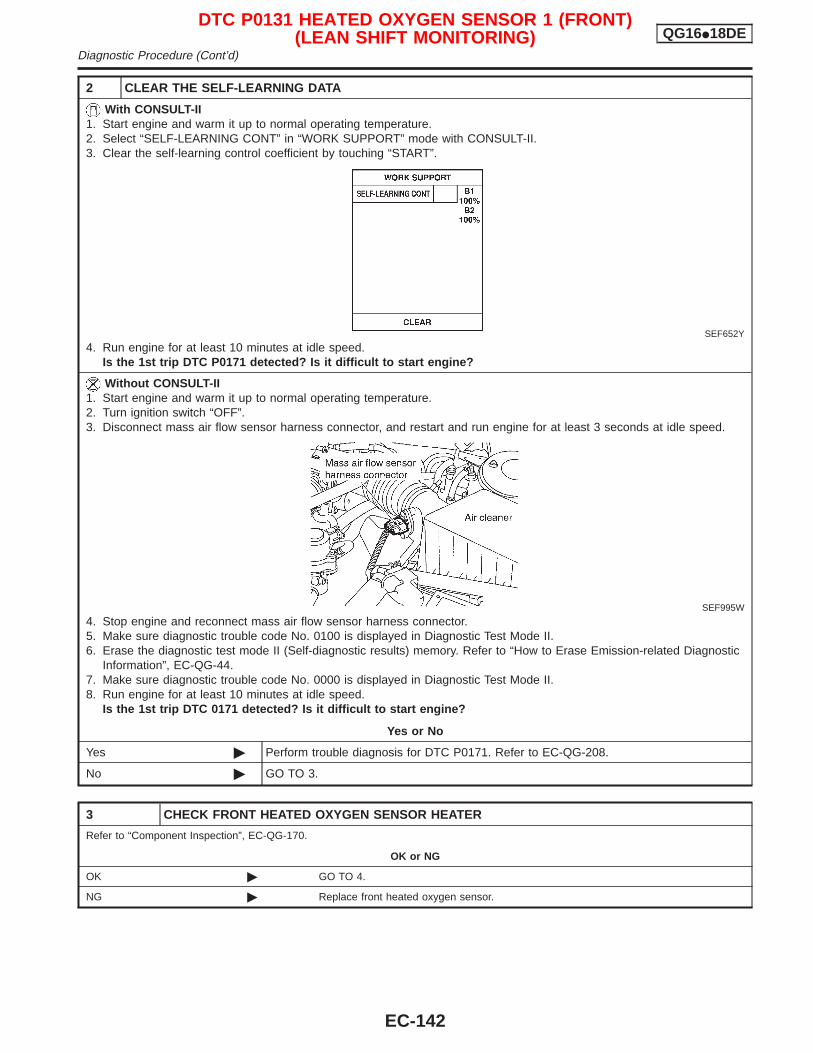
2 CLEAR THE SELF-LEARNING DATA
With CONSULT-II1. Start engine and warm it up to normal operating temperature.2. Select “SELF-LEARNING CONT” in “WORK SUPPORT” mode with CONSULT-II.3. Clear the self-learning control coefficient by touching “START”.
SEF652Y
4. Run engine for at least 10 minutes at idle speed.Is the 1st trip DTC P0171 detected? Is it difficult to start engine?
Without CONSULT-II1. Start engine and warm it up to normal operating temperature.2. Turn ignition switch “OFF”.3. Disconnect mass air flow sensor harness connector, and restart and run engine for at least 3 seconds at idle speed.
SEF995W
4. Stop engine and reconnect mass air flow sensor harness connector.5. Make sure diagnostic trouble code No. 0100 is displayed in Diagnostic Test Mode II.6. Erase the diagnostic test mode II (Self-diagnostic results) memory. Refer to “How to Erase Emission-related Diagnostic
Information”, EC-QG-44.7. Make sure diagnostic trouble code No. 0000 is displayed in Diagnostic Test Mode II.8. Run engine for at least 10 minutes at idle speed.
Is the 1st trip DTC 0171 detected? Is it difficult to start engine?
Yes or No
Yes © Perform trouble diagnosis for DTC P0171. Refer to EC-QG-208.
No © GO TO 3.
3 CHECK FRONT HEATED OXYGEN SENSOR HEATER
Refer to “Component Inspection”, EC-QG-170.
OK or NG
OK © GO TO 4.
NG © Replace front heated oxygen sensor.
DTC P0131 HEATED OXYGEN SENSOR 1 (FRONT)(LEAN SHIFT MONITORING) QG16I18DE
Diagnostic Procedure (Cont’d)
EC-142
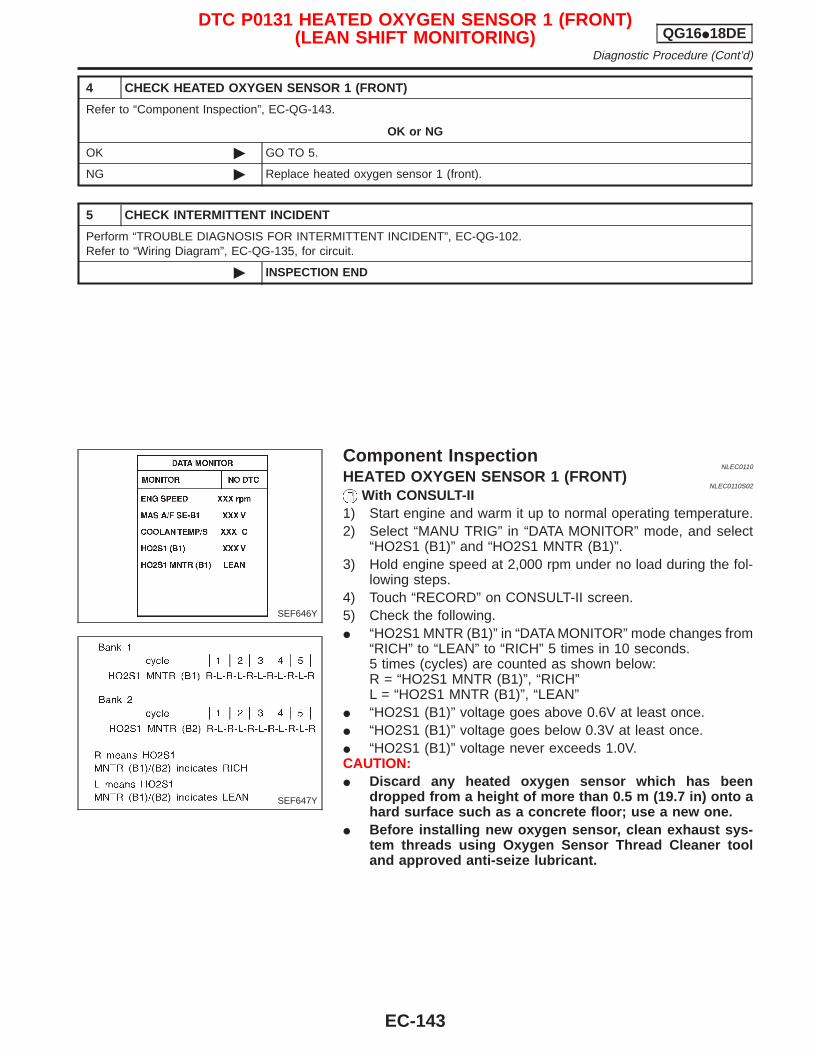
4 CHECK HEATED OXYGEN SENSOR 1 (FRONT)
Refer to “Component Inspection”, EC-QG-143.
OK or NG
OK © GO TO 5.
NG © Replace heated oxygen sensor 1 (front).
5 CHECK INTERMITTENT INCIDENT
Perform “TROUBLE DIAGNOSIS FOR INTERMITTENT INCIDENT”, EC-QG-102.Refer to “Wiring Diagram”, EC-QG-135, for circuit.
© INSPECTION END
Component InspectionNLEC0110
HEATED OXYGEN SENSOR 1 (FRONT)NLEC0110S02
With CONSULT-II1) Start engine and warm it up to normal operating temperature.2) Select “MANU TRIG” in “DATA MONITOR” mode, and select
“HO2S1 (B1)” and “HO2S1 MNTR (B1)”.3) Hold engine speed at 2,000 rpm under no load during the fol-
lowing steps.4) Touch “RECORD” on CONSULT-II screen.5) Check the following.I “HO2S1 MNTR (B1)” in “DATA MONITOR” mode changes from
“RICH” to “LEAN” to “RICH” 5 times in 10 seconds.5 times (cycles) are counted as shown below:R = “HO2S1 MNTR (B1)”, “RICH”L = “HO2S1 MNTR (B1)”, “LEAN”
I “HO2S1 (B1)” voltage goes above 0.6V at least once.I “HO2S1 (B1)” voltage goes below 0.3V at least once.I “HO2S1 (B1)” voltage never exceeds 1.0V.CAUTION:I Discard any heated oxygen sensor which has been
dropped from a height of more than 0.5 m (19.7 in) onto ahard surface such as a concrete floor; use a new one.
I Before installing new oxygen sensor, clean exhaust sys-tem threads using Oxygen Sensor Thread Cleaner tooland approved anti-seize lubricant.
SEF646Y
SEF647Y
DTC P0131 HEATED OXYGEN SENSOR 1 (FRONT)(LEAN SHIFT MONITORING) QG16I18DE
Diagnostic Procedure (Cont’d)
EC-143
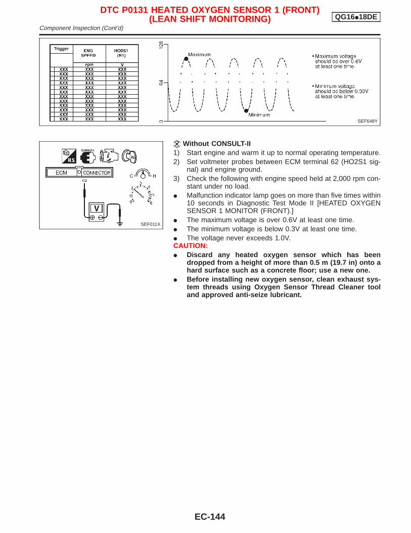
Without CONSULT-II1) Start engine and warm it up to normal operating temperature.2) Set voltmeter probes between ECM terminal 62 (HO2S1 sig-
nal) and engine ground.3) Check the following with engine speed held at 2,000 rpm con-
stant under no load.I Malfunction indicator lamp goes on more than five times within
10 seconds in Diagnostic Test Mode II [HEATED OXYGENSENSOR 1 MONITOR (FRONT).]
I The maximum voltage is over 0.6V at least one time.I The minimum voltage is below 0.3V at least one time.I The voltage never exceeds 1.0V.CAUTION:I Discard any heated oxygen sensor which has been
dropped from a height of more than 0.5 m (19.7 in) onto ahard surface such as a concrete floor; use a new one.
I Before installing new oxygen sensor, clean exhaust sys-tem threads using Oxygen Sensor Thread Cleaner tooland approved anti-seize lubricant.
SEF648Y
SEF011X
DTC P0131 HEATED OXYGEN SENSOR 1 (FRONT)(LEAN SHIFT MONITORING) QG16I18DE
Component Inspection (Cont’d)
EC-144

Component DescriptionNLEC0111
The heated oxygen sensor 1 (front) is placed into the exhaustmanifold. It detects the amount of oxygen in the exhaust gas com-pared to the outside air. The heated oxygen sensor 1 (front) has aclosed-end tube made of ceramic zirconia. The zirconia generatesvoltage from approximately 1V in richer conditions to 0V in leanerconditions. The heated oxygen sensor 1 (front) signal is sent to theECM. The ECM adjusts the injection pulse duration to achieve theideal air-fuel ratio. The ideal air-fuel ratio occurs near the radicalchange from 1V to 0V.
CONSULT-II Reference Value in Data MonitorMode
NLEC0112
Specification data are reference values.
MONITOR ITEM CONDITION SPECIFICATION
HO2S1 (B1)
I Engine: After warming upMaintaining engine speed at 2,000rpm
0 - 0.3V +, Approx. 0.6 - 1.0V
HO2S1 MNTR(B1)
LEAN +, RICHChanges more than 5 times during10 seconds.
ECM Terminals and Reference ValueNLEC0113
Specification data are reference values and are measured between each terminal and ground.CAUTION:Do not use ECM ground terminals when measuring input/output voltage. Doing so may result in dam-age to the ECM’s transistor. Use a ground other than ECM terminals, such as the ground.
TERMI-NALNO.
WIRECOLOR
ITEM CONDITION DATA (DC Voltage)
62 RHeated oxygen sensor1 (front)
[Engine is running]I After warming up to normal operating temperature
and engine speed is 2,000 rpm
0 - Approximately 1.0V
SEF008W
SEF463R
SEF288D
DTC P0132 HEATED OXYGEN SENSOR 1 (FRONT)(RICH SHIFT MONITORING) QG16I18DE
Component Description
EC-145
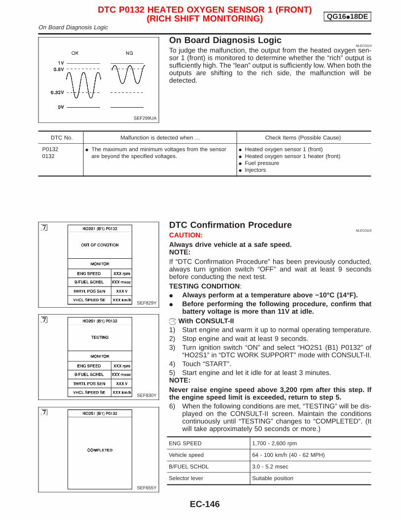
On Board Diagnosis LogicNLEC0114
To judge the malfunction, the output from the heated oxygen sen-sor 1 (front) is monitored to determine whether the “rich” output issufficiently high. The “lean” output is sufficiently low. When both theoutputs are shifting to the rich side, the malfunction will bedetected.
DTC No. Malfunction is detected when ... Check Items (Possible Cause)
P01320132
I The maximum and minimum voltages from the sensorare beyond the specified voltages.
I Heated oxygen sensor 1 (front)I Heated oxygen sensor 1 heater (front)I Fuel pressureI Injectors
DTC Confirmation ProcedureNLEC0115
CAUTION:Always drive vehicle at a safe speed.NOTE:If “DTC Confirmation Procedure” has been previously conducted,always turn ignition switch “OFF” and wait at least 9 secondsbefore conducting the next test.TESTING CONDITION:I Always perform at a temperature above −10°C (14°F).I Before performing the following procedure, confirm that
battery voltage is more than 11V at idle.With CONSULT-II
1) Start engine and warm it up to normal operating temperature.2) Stop engine and wait at least 9 seconds.3) Turn ignition switch “ON” and select “HO2S1 (B1) P0132” of
“HO2S1” in “DTC WORK SUPPORT” mode with CONSULT-II.4) Touch “START”.5) Start engine and let it idle for at least 3 minutes.NOTE:Never raise engine speed above 3,200 rpm after this step. Ifthe engine speed limit is exceeded, return to step 5.6) When the following conditions are met, “TESTING” will be dis-
played on the CONSULT-II screen. Maintain the conditionscontinuously until “TESTING” changes to “COMPLETED”. (Itwill take approximately 50 seconds or more.)
ENG SPEED 1,700 - 2,600 rpm
Vehicle speed 64 - 100 km/h (40 - 62 MPH)
B/FUEL SCHDL 3.0 - 5.2 msec
Selector lever Suitable position
SEF299UA
SEF829Y
SEF830Y
SEF655Y
DTC P0132 HEATED OXYGEN SENSOR 1 (FRONT)(RICH SHIFT MONITORING) QG16I18DE
On Board Diagnosis Logic
EC-146
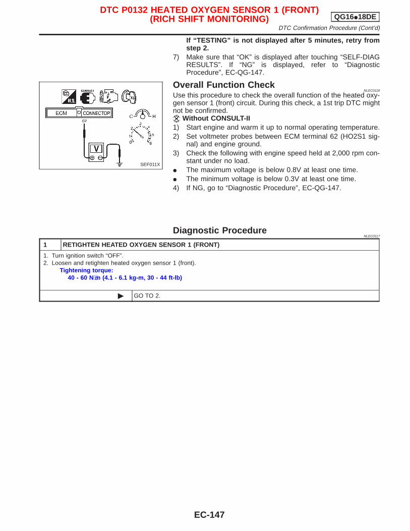
If “TESTING” is not displayed after 5 minutes, retry fromstep 2.
7) Make sure that “OK” is displayed after touching “SELF-DIAGRESULTS”. If “NG” is displayed, refer to “DiagnosticProcedure”, EC-QG-147.
Overall Function CheckNLEC0116
Use this procedure to check the overall function of the heated oxy-gen sensor 1 (front) circuit. During this check, a 1st trip DTC mightnot be confirmed.
Without CONSULT-II1) Start engine and warm it up to normal operating temperature.2) Set voltmeter probes between ECM terminal 62 (HO2S1 sig-
nal) and engine ground.3) Check the following with engine speed held at 2,000 rpm con-
stant under no load.I The maximum voltage is below 0.8V at least one time.I The minimum voltage is below 0.3V at least one time.4) If NG, go to “Diagnostic Procedure”, EC-QG-147.
Diagnostic ProcedureNLEC0117
1 RETIGHTEN HEATED OXYGEN SENSOR 1 (FRONT)
1. Turn ignition switch “OFF”.2. Loosen and retighten heated oxygen sensor 1 (front).
Tightening torque:40 - 60 N⋅m (4.1 - 6.1 kg-m, 30 - 44 ft-lb)
© GO TO 2.
SEF011X
DTC P0132 HEATED OXYGEN SENSOR 1 (FRONT)(RICH SHIFT MONITORING) QG16I18DE
DTC Confirmation Procedure (Cont’d)
EC-147
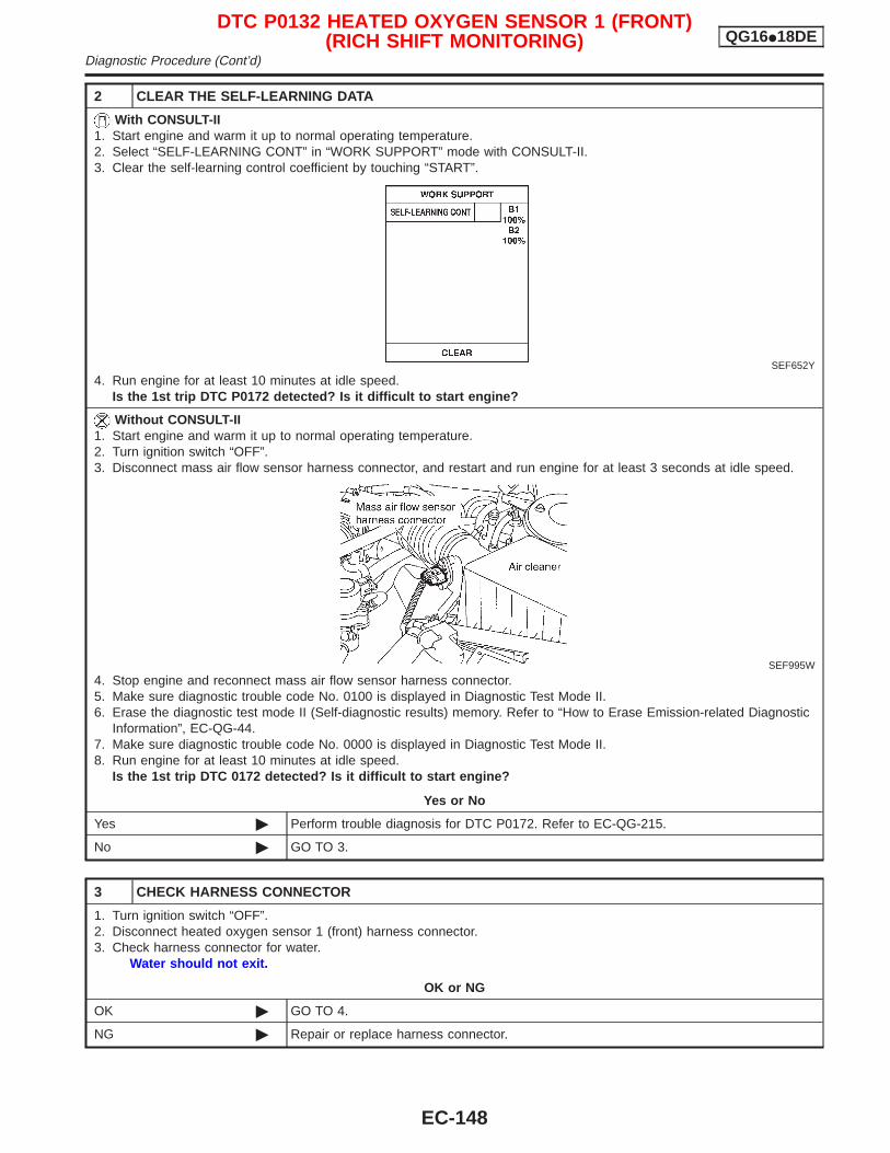
2 CLEAR THE SELF-LEARNING DATA
With CONSULT-II1. Start engine and warm it up to normal operating temperature.2. Select “SELF-LEARNING CONT” in “WORK SUPPORT” mode with CONSULT-II.3. Clear the self-learning control coefficient by touching “START”.
SEF652Y
4. Run engine for at least 10 minutes at idle speed.Is the 1st trip DTC P0172 detected? Is it difficult to start engine?
Without CONSULT-II1. Start engine and warm it up to normal operating temperature.2. Turn ignition switch “OFF”.3. Disconnect mass air flow sensor harness connector, and restart and run engine for at least 3 seconds at idle speed.
SEF995W
4. Stop engine and reconnect mass air flow sensor harness connector.5. Make sure diagnostic trouble code No. 0100 is displayed in Diagnostic Test Mode II.6. Erase the diagnostic test mode II (Self-diagnostic results) memory. Refer to “How to Erase Emission-related Diagnostic
Information”, EC-QG-44.7. Make sure diagnostic trouble code No. 0000 is displayed in Diagnostic Test Mode II.8. Run engine for at least 10 minutes at idle speed.
Is the 1st trip DTC 0172 detected? Is it difficult to start engine?
Yes or No
Yes © Perform trouble diagnosis for DTC P0172. Refer to EC-QG-215.
No © GO TO 3.
3 CHECK HARNESS CONNECTOR
1. Turn ignition switch “OFF”.2. Disconnect heated oxygen sensor 1 (front) harness connector.3. Check harness connector for water.
Water should not exit.
OK or NG
OK © GO TO 4.
NG © Repair or replace harness connector.
DTC P0132 HEATED OXYGEN SENSOR 1 (FRONT)(RICH SHIFT MONITORING) QG16I18DE
Diagnostic Procedure (Cont’d)
EC-148
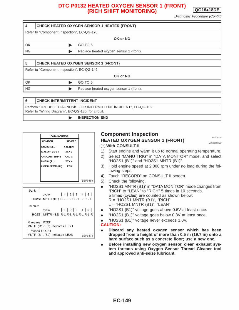
4 CHECK HEATED OXYGEN SENSOR 1 HEATER (FRONT)
Refer to “Component Inspection”, EC-QG-170.
OK or NG
OK © GO TO 5.
NG © Replace heated oxygen sensor 1 (front).
5 CHECK HEATED OXYGEN SENSOR 1 (FRONT)
Refer to “Component Inspection”, EC-QG-149.
OK or NG
OK © GO TO 6.
NG © Replace heated oxygen sensor 1 (front).
6 CHECK INTERMITTENT INCIDENT
Perform “TROUBLE DIAGNOSIS FOR INTERMITTENT INCIDENT”, EC-QG-102.Refer to “Wiring Diagram”, EC-QG-135, for circuit.
© INSPECTION END
Component InspectionNLEC0118
HEATED OXYGEN SENSOR 1 (FRONT)NLEC0118S02
With CONSULT-II1) Start engine and warm it up to normal operating temperature.2) Select “MANU TRIG” in “DATA MONITOR” mode, and select
“HO2S1 (B1)” and “HO2S1 MNTR (B1)”.3) Hold engine speed at 2,000 rpm under no load during the fol-
lowing steps.4) Touch “RECORD” on CONSULT-II screen.5) Check the following.I “HO2S1 MNTR (B1)” in “DATA MONITOR” mode changes from
“RICH” to “LEAN” to “RICH” 5 times in 10 seconds.5 times (cycles) are counted as shown below:R = “HO2S1 MNTR (B1)”, “RICH”L = “HO2S1 MNTR (B1)”, “LEAN”
I “HO2S1 (B1)” voltage goes above 0.6V at least once.I “HO2S1 (B1)” voltage goes below 0.3V at least once.I “HO2S1 (B1)” voltage never exceeds 1.0V.CAUTION:I Discard any heated oxygen sensor which has been
dropped from a height of more than 0.5 m (19.7 in) onto ahard surface such as a concrete floor; use a new one.
I Before installing new oxygen sensor, clean exhaust sys-tem threads using Oxygen Sensor Thread Cleaner tooland approved anti-seize lubricant.
SEF646Y
SEF647Y
DTC P0132 HEATED OXYGEN SENSOR 1 (FRONT)(RICH SHIFT MONITORING) QG16I18DE
Diagnostic Procedure (Cont’d)
EC-149
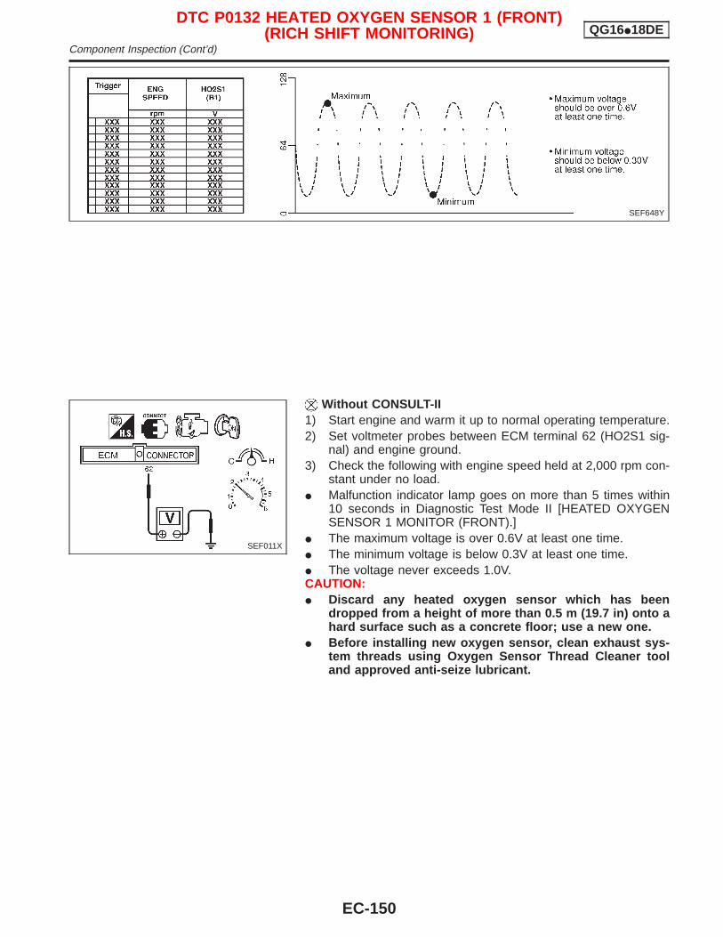
Without CONSULT-II1) Start engine and warm it up to normal operating temperature.2) Set voltmeter probes between ECM terminal 62 (HO2S1 sig-
nal) and engine ground.3) Check the following with engine speed held at 2,000 rpm con-
stant under no load.I Malfunction indicator lamp goes on more than 5 times within
10 seconds in Diagnostic Test Mode II [HEATED OXYGENSENSOR 1 MONITOR (FRONT).]
I The maximum voltage is over 0.6V at least one time.I The minimum voltage is below 0.3V at least one time.I The voltage never exceeds 1.0V.CAUTION:I Discard any heated oxygen sensor which has been
dropped from a height of more than 0.5 m (19.7 in) onto ahard surface such as a concrete floor; use a new one.
I Before installing new oxygen sensor, clean exhaust sys-tem threads using Oxygen Sensor Thread Cleaner tooland approved anti-seize lubricant.
SEF648Y
SEF011X
DTC P0132 HEATED OXYGEN SENSOR 1 (FRONT)(RICH SHIFT MONITORING) QG16I18DE
Component Inspection (Cont’d)
EC-150

Component DescriptionNLEC0119
The heated oxygen sensor 1 (front) is placed into the exhaustmanifold. It detects the amount of oxygen in the exhaust gas com-pared to the outside air. The heated oxygen sensor 1 (front) has aclosed-end tube made of ceramic zirconia. The zirconia generatesvoltage from approximately 1V in richer conditions to 0V in leanerconditions. The heated oxygen sensor 1 (front) signal is sent to theECM. The ECM adjusts the injection pulse duration to achieve theideal air-fuel ratio. The ideal air-fuel ratio occurs near the radicalchange from 1V to 0V.
CONSULT-II Reference Value in Data MonitorMode
NLEC0120
Specification data are reference values.
MONITOR ITEM CONDITION SPECIFICATION
HO2S1 (B1)
I Engine: After warming upMaintaining engine speed at 2,000rpm
0 - 0.3V +, Approx. 0.6 - 1.0V
HO2S1 MNTR(B1)
LEAN +, RICHChanges more than 5 times during10 seconds.
ECM Terminals and Reference ValueNLEC0121
Specification data are reference values and are measured between each terminal and ground.CAUTION:Do not use ECM ground terminals when measuring input/output voltage. Doing so may result in dam-age to the ECM’s transistor. Use a ground other than ECM terminals, such as the ground.
TERMI-NALNO.
WIRECOLOR
ITEM CONDITION DATA (DC Voltage)
62 RHeated oxygen sensor1 (front)
[Engine is running]I After warming up to normal operating temperature
and engine speed is 2,000 rpm
0 - Approximately 1.0V
SEF008W
SEF463R
SEF288D
DTC P0133 HEATED OXYGEN SENSOR 1 (FRONT)(RESPONSE MONITORING) QG16I18DE
Component Description
EC-151
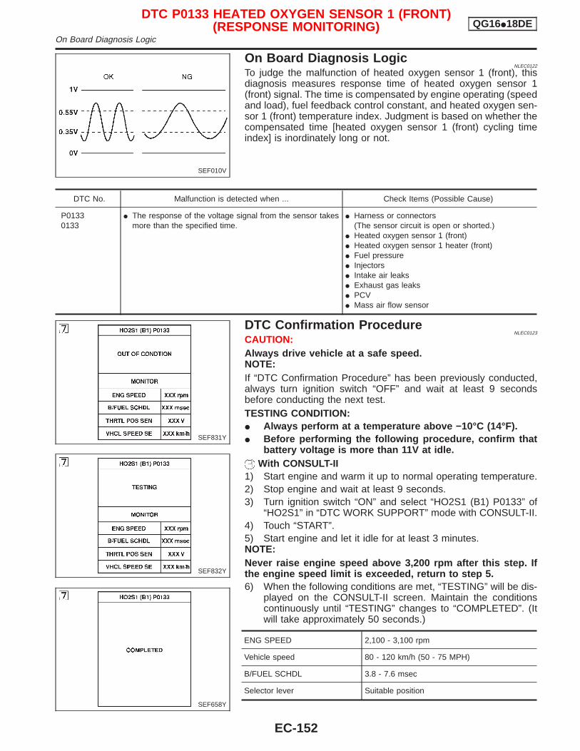
On Board Diagnosis LogicNLEC0122
To judge the malfunction of heated oxygen sensor 1 (front), thisdiagnosis measures response time of heated oxygen sensor 1(front) signal. The time is compensated by engine operating (speedand load), fuel feedback control constant, and heated oxygen sen-sor 1 (front) temperature index. Judgment is based on whether thecompensated time [heated oxygen sensor 1 (front) cycling timeindex] is inordinately long or not.
DTC No. Malfunction is detected when ... Check Items (Possible Cause)
P01330133
I The response of the voltage signal from the sensor takesmore than the specified time.
I Harness or connectors(The sensor circuit is open or shorted.)
I Heated oxygen sensor 1 (front)I Heated oxygen sensor 1 heater (front)I Fuel pressureI InjectorsI Intake air leaksI Exhaust gas leaksI PCVI Mass air flow sensor
DTC Confirmation ProcedureNLEC0123
CAUTION:Always drive vehicle at a safe speed.NOTE:If “DTC Confirmation Procedure” has been previously conducted,always turn ignition switch “OFF” and wait at least 9 secondsbefore conducting the next test.TESTING CONDITION:I Always perform at a temperature above −10°C (14°F).I Before performing the following procedure, confirm that
battery voltage is more than 11V at idle.With CONSULT-II
1) Start engine and warm it up to normal operating temperature.2) Stop engine and wait at least 9 seconds.3) Turn ignition switch “ON” and select “HO2S1 (B1) P0133” of
“HO2S1” in “DTC WORK SUPPORT” mode with CONSULT-II.4) Touch “START”.5) Start engine and let it idle for at least 3 minutes.NOTE:Never raise engine speed above 3,200 rpm after this step. Ifthe engine speed limit is exceeded, return to step 5.6) When the following conditions are met, “TESTING” will be dis-
played on the CONSULT-II screen. Maintain the conditionscontinuously until “TESTING” changes to “COMPLETED”. (Itwill take approximately 50 seconds.)
ENG SPEED 2,100 - 3,100 rpm
Vehicle speed 80 - 120 km/h (50 - 75 MPH)
B/FUEL SCHDL 3.8 - 7.6 msec
Selector lever Suitable position
SEF010V
SEF831Y
SEF832Y
SEF658Y
DTC P0133 HEATED OXYGEN SENSOR 1 (FRONT)(RESPONSE MONITORING) QG16I18DE
On Board Diagnosis Logic
EC-152
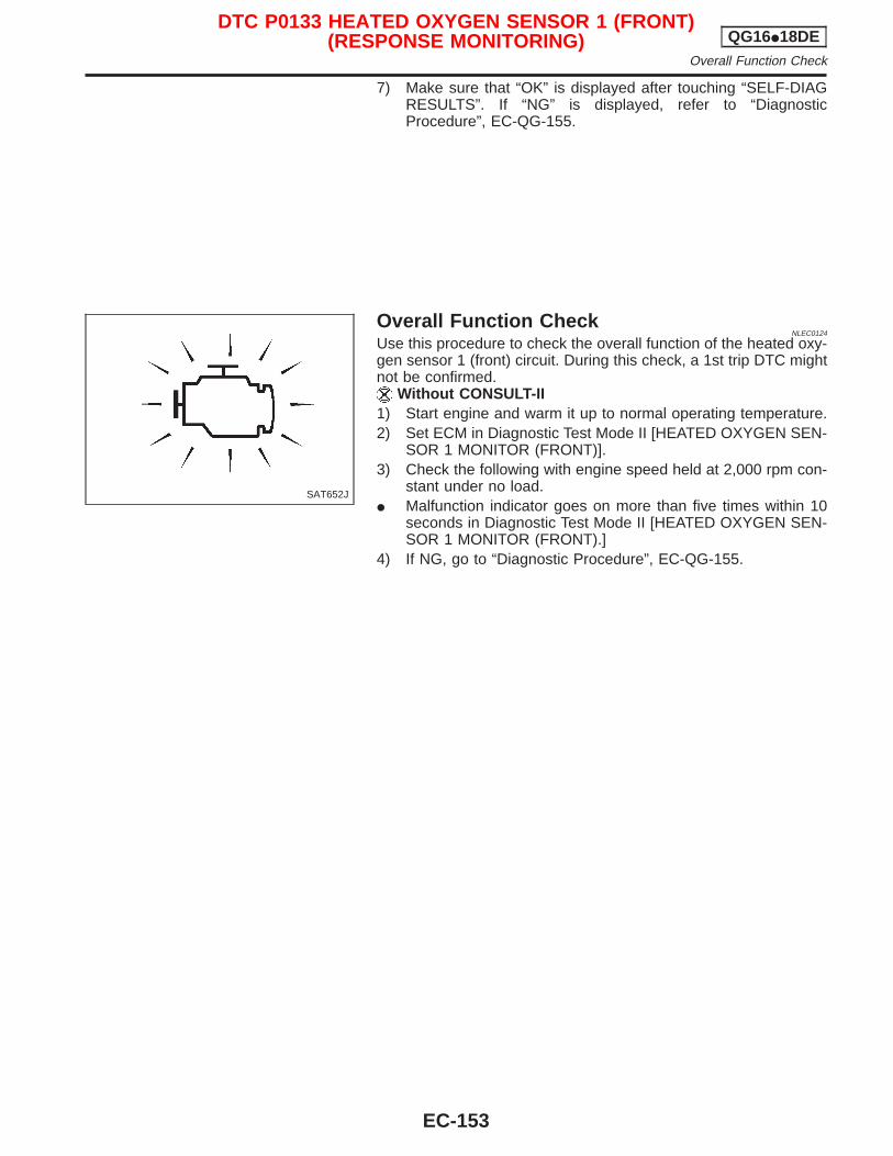
7) Make sure that “OK” is displayed after touching “SELF-DIAGRESULTS”. If “NG” is displayed, refer to “DiagnosticProcedure”, EC-QG-155.
Overall Function CheckNLEC0124
Use this procedure to check the overall function of the heated oxy-gen sensor 1 (front) circuit. During this check, a 1st trip DTC mightnot be confirmed.
Without CONSULT-II1) Start engine and warm it up to normal operating temperature.2) Set ECM in Diagnostic Test Mode II [HEATED OXYGEN SEN-
SOR 1 MONITOR (FRONT)].3) Check the following with engine speed held at 2,000 rpm con-
stant under no load.I Malfunction indicator goes on more than five times within 10
seconds in Diagnostic Test Mode II [HEATED OXYGEN SEN-SOR 1 MONITOR (FRONT).]
4) If NG, go to “Diagnostic Procedure”, EC-QG-155.
SAT652J
DTC P0133 HEATED OXYGEN SENSOR 1 (FRONT)(RESPONSE MONITORING) QG16I18DE
Overall Function Check
EC-153
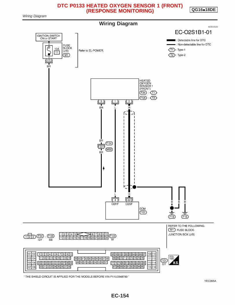
Wiring DiagramNCEC0125
YEC065A
DTC P0133 HEATED OXYGEN SENSOR 1 (FRONT)(RESPONSE MONITORING) QG16I18DE
Wiring Diagram
EC-154
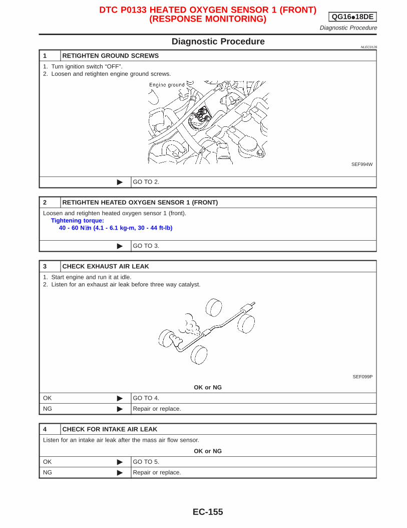
Diagnostic ProcedureNLEC0126
1 RETIGHTEN GROUND SCREWS
1. Turn ignition switch “OFF”.2. Loosen and retighten engine ground screws.
SEF994W
© GO TO 2.
2 RETIGHTEN HEATED OXYGEN SENSOR 1 (FRONT)
Loosen and retighten heated oxygen sensor 1 (front).Tightening torque:
40 - 60 N⋅m (4.1 - 6.1 kg-m, 30 - 44 ft-lb)
© GO TO 3.
3 CHECK EXHAUST AIR LEAK
1. Start engine and run it at idle.2. Listen for an exhaust air leak before three way catalyst.
SEF099P
OK or NG
OK © GO TO 4.
NG © Repair or replace.
4 CHECK FOR INTAKE AIR LEAK
Listen for an intake air leak after the mass air flow sensor.
OK or NG
OK © GO TO 5.
NG © Repair or replace.
DTC P0133 HEATED OXYGEN SENSOR 1 (FRONT)(RESPONSE MONITORING) QG16I18DE
Diagnostic Procedure
EC-155
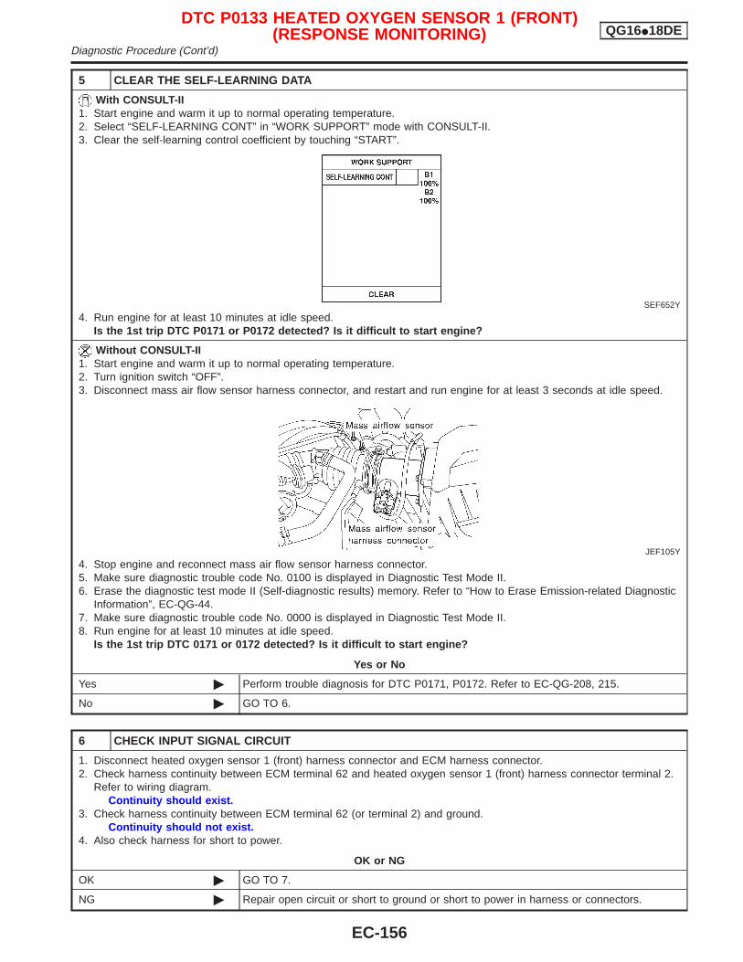
5 CLEAR THE SELF-LEARNING DATA
With CONSULT-II1. Start engine and warm it up to normal operating temperature.2. Select “SELF-LEARNING CONT” in “WORK SUPPORT” mode with CONSULT-II.3. Clear the self-learning control coefficient by touching “START”.
SEF652Y
4. Run engine for at least 10 minutes at idle speed.Is the 1st trip DTC P0171 or P0172 detected? Is it difficult to start engine?
Without CONSULT-II1. Start engine and warm it up to normal operating temperature.2. Turn ignition switch “OFF”.3. Disconnect mass air flow sensor harness connector, and restart and run engine for at least 3 seconds at idle speed.
JEF105Y
4. Stop engine and reconnect mass air flow sensor harness connector.5. Make sure diagnostic trouble code No. 0100 is displayed in Diagnostic Test Mode II.6. Erase the diagnostic test mode II (Self-diagnostic results) memory. Refer to “How to Erase Emission-related Diagnostic
Information”, EC-QG-44.7. Make sure diagnostic trouble code No. 0000 is displayed in Diagnostic Test Mode II.8. Run engine for at least 10 minutes at idle speed.
Is the 1st trip DTC 0171 or 0172 detected? Is it difficult to start engine?
Yes or No
Yes © Perform trouble diagnosis for DTC P0171, P0172. Refer to EC-QG-208, 215.
No © GO TO 6.
6 CHECK INPUT SIGNAL CIRCUIT
1. Disconnect heated oxygen sensor 1 (front) harness connector and ECM harness connector.2. Check harness continuity between ECM terminal 62 and heated oxygen sensor 1 (front) harness connector terminal 2.
Refer to wiring diagram.Continuity should exist.
3. Check harness continuity between ECM terminal 62 (or terminal 2) and ground.Continuity should not exist.
4. Also check harness for short to power.
OK or NG
OK © GO TO 7.
NG © Repair open circuit or short to ground or short to power in harness or connectors.
DTC P0133 HEATED OXYGEN SENSOR 1 (FRONT)(RESPONSE MONITORING) QG16I18DE
Diagnostic Procedure (Cont’d)
EC-156
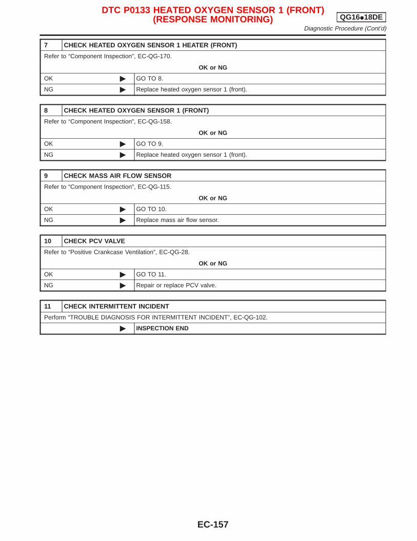
7 CHECK HEATED OXYGEN SENSOR 1 HEATER (FRONT)
Refer to “Component Inspection”, EC-QG-170.
OK or NG
OK © GO TO 8.
NG © Replace heated oxygen sensor 1 (front).
8 CHECK HEATED OXYGEN SENSOR 1 (FRONT)
Refer to “Component Inspection”, EC-QG-158.
OK or NG
OK © GO TO 9.
NG © Replace heated oxygen sensor 1 (front).
9 CHECK MASS AIR FLOW SENSOR
Refer to “Component Inspection”, EC-QG-115.
OK or NG
OK © GO TO 10.
NG © Replace mass air flow sensor.
10 CHECK PCV VALVE
Refer to “Positive Crankcase Ventilation”, EC-QG-28.
OK or NG
OK © GO TO 11.
NG © Repair or replace PCV valve.
11 CHECK INTERMITTENT INCIDENT
Perform “TROUBLE DIAGNOSIS FOR INTERMITTENT INCIDENT”, EC-QG-102.
© INSPECTION END
DTC P0133 HEATED OXYGEN SENSOR 1 (FRONT)(RESPONSE MONITORING) QG16I18DE
Diagnostic Procedure (Cont’d)
EC-157
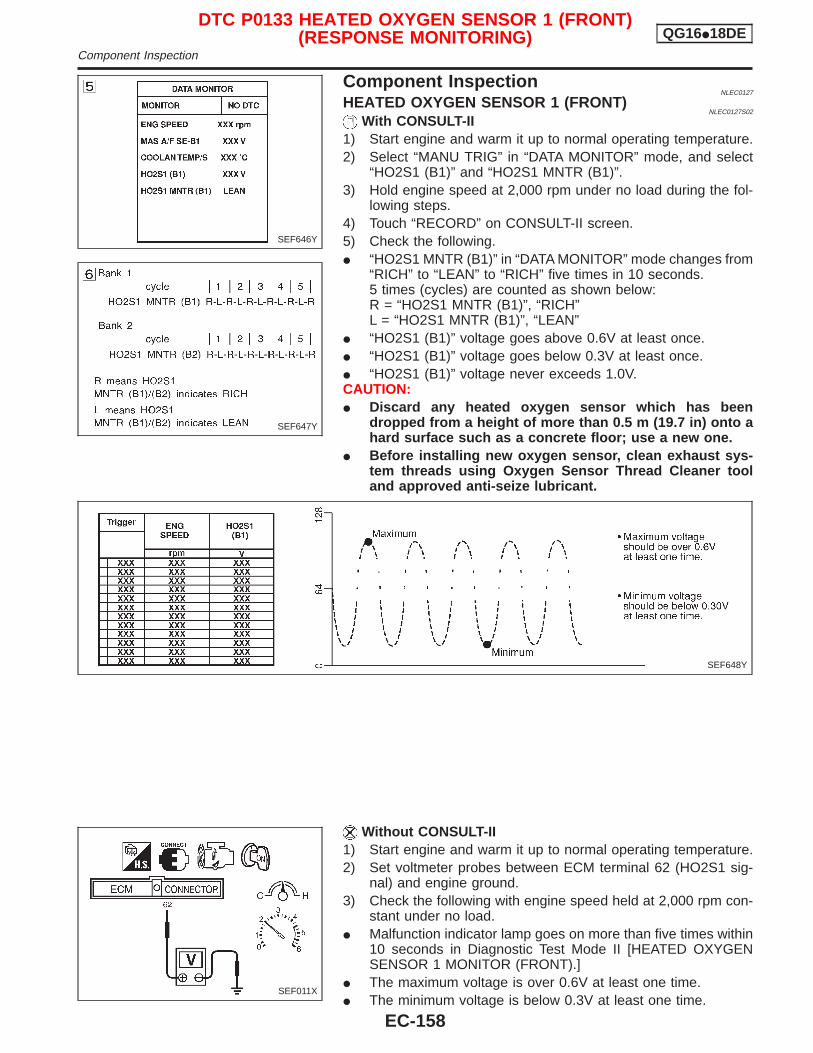
Component InspectionNLEC0127
HEATED OXYGEN SENSOR 1 (FRONT)NLEC0127S02
With CONSULT-II1) Start engine and warm it up to normal operating temperature.2) Select “MANU TRIG” in “DATA MONITOR” mode, and select
“HO2S1 (B1)” and “HO2S1 MNTR (B1)”.3) Hold engine speed at 2,000 rpm under no load during the fol-
lowing steps.4) Touch “RECORD” on CONSULT-II screen.5) Check the following.I “HO2S1 MNTR (B1)” in “DATA MONITOR” mode changes from
“RICH” to “LEAN” to “RICH” five times in 10 seconds.5 times (cycles) are counted as shown below:R = “HO2S1 MNTR (B1)”, “RICH”L = “HO2S1 MNTR (B1)”, “LEAN”
I “HO2S1 (B1)” voltage goes above 0.6V at least once.I “HO2S1 (B1)” voltage goes below 0.3V at least once.I “HO2S1 (B1)” voltage never exceeds 1.0V.CAUTION:I Discard any heated oxygen sensor which has been
dropped from a height of more than 0.5 m (19.7 in) onto ahard surface such as a concrete floor; use a new one.
I Before installing new oxygen sensor, clean exhaust sys-tem threads using Oxygen Sensor Thread Cleaner tooland approved anti-seize lubricant.
Without CONSULT-II1) Start engine and warm it up to normal operating temperature.2) Set voltmeter probes between ECM terminal 62 (HO2S1 sig-
nal) and engine ground.3) Check the following with engine speed held at 2,000 rpm con-
stant under no load.I Malfunction indicator lamp goes on more than five times within
10 seconds in Diagnostic Test Mode II [HEATED OXYGENSENSOR 1 MONITOR (FRONT).]
I The maximum voltage is over 0.6V at least one time.I The minimum voltage is below 0.3V at least one time.
SEF646Y
SEF647Y
SEF648Y
SEF011X
DTC P0133 HEATED OXYGEN SENSOR 1 (FRONT)(RESPONSE MONITORING) QG16I18DE
Component Inspection
EC-158
I The voltage never exceeds 1.0V.CAUTION:I Discard any heated oxygen sensor which has been
dropped from a height of more than 0.5 m (19.7 in) onto ahard surface such as a concrete floor; use a new one.
I Before installing new oxygen sensor, clean exhaust sys-tem threads using Oxygen Sensor Thread Cleaner tooland approved anti-seize lubricant.
DTC P0133 HEATED OXYGEN SENSOR 1 (FRONT)(RESPONSE MONITORING) QG16I18DE
Component Inspection (Cont’d)
EC-159
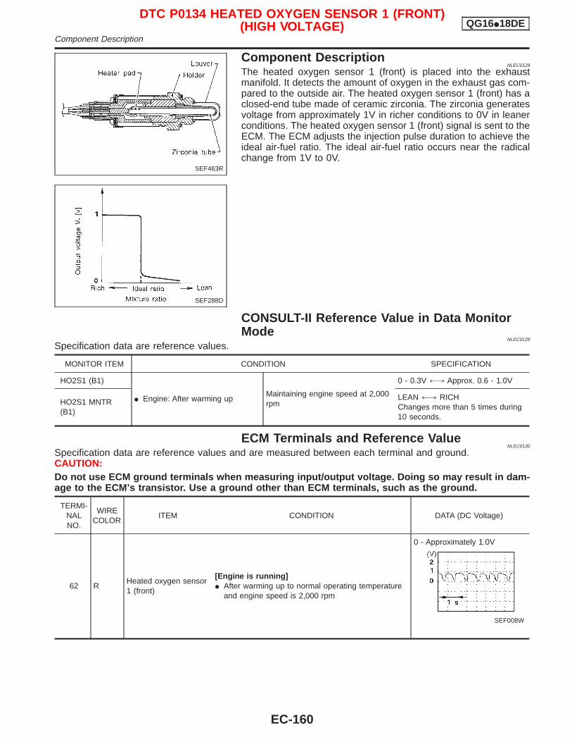
Component DescriptionNLEC0128
The heated oxygen sensor 1 (front) is placed into the exhaustmanifold. It detects the amount of oxygen in the exhaust gas com-pared to the outside air. The heated oxygen sensor 1 (front) has aclosed-end tube made of ceramic zirconia. The zirconia generatesvoltage from approximately 1V in richer conditions to 0V in leanerconditions. The heated oxygen sensor 1 (front) signal is sent to theECM. The ECM adjusts the injection pulse duration to achieve theideal air-fuel ratio. The ideal air-fuel ratio occurs near the radicalchange from 1V to 0V.
CONSULT-II Reference Value in Data MonitorMode
NLEC0129
Specification data are reference values.
MONITOR ITEM CONDITION SPECIFICATION
HO2S1 (B1)
I Engine: After warming upMaintaining engine speed at 2,000rpm
0 - 0.3V +, Approx. 0.6 - 1.0V
HO2S1 MNTR(B1)
LEAN +, RICHChanges more than 5 times during10 seconds.
ECM Terminals and Reference ValueNLEC0130
Specification data are reference values and are measured between each terminal and ground.CAUTION:Do not use ECM ground terminals when measuring input/output voltage. Doing so may result in dam-age to the ECM’s transistor. Use a ground other than ECM terminals, such as the ground.
TERMI-NALNO.
WIRECOLOR
ITEM CONDITION DATA (DC Voltage)
62 RHeated oxygen sensor1 (front)
[Engine is running]I After warming up to normal operating temperature
and engine speed is 2,000 rpm
0 - Approximately 1.0V
SEF008W
SEF463R
SEF288D
DTC P0134 HEATED OXYGEN SENSOR 1 (FRONT)(HIGH VOLTAGE) QG16I18DE
Component Description
EC-160
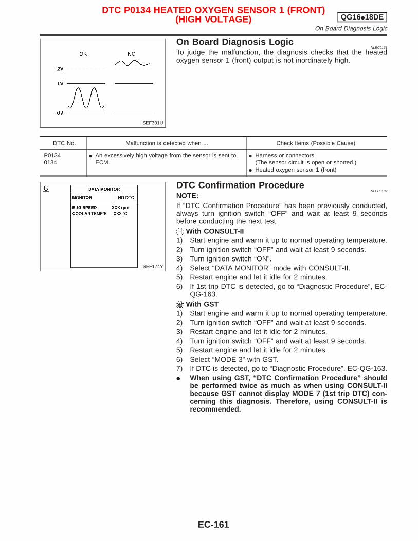
On Board Diagnosis LogicNLEC0131
To judge the malfunction, the diagnosis checks that the heatedoxygen sensor 1 (front) output is not inordinately high.
DTC No. Malfunction is detected when ... Check Items (Possible Cause)
P01340134
I An excessively high voltage from the sensor is sent toECM.
I Harness or connectors(The sensor circuit is open or shorted.)
I Heated oxygen sensor 1 (front)
DTC Confirmation ProcedureNLEC0132
NOTE:If “DTC Confirmation Procedure” has been previously conducted,always turn ignition switch “OFF” and wait at least 9 secondsbefore conducting the next test.
With CONSULT-II1) Start engine and warm it up to normal operating temperature.2) Turn ignition switch “OFF” and wait at least 9 seconds.3) Turn ignition switch “ON”.4) Select “DATA MONITOR” mode with CONSULT-II.5) Restart engine and let it idle for 2 minutes.6) If 1st trip DTC is detected, go to “Diagnostic Procedure”, EC-
QG-163.With GST
1) Start engine and warm it up to normal operating temperature.2) Turn ignition switch “OFF” and wait at least 9 seconds.3) Restart engine and let it idle for 2 minutes.4) Turn ignition switch “OFF” and wait at least 9 seconds.5) Restart engine and let it idle for 2 minutes.6) Select “MODE 3” with GST.7) If DTC is detected, go to “Diagnostic Procedure”, EC-QG-163.I When using GST, “DTC Confirmation Procedure” should
be performed twice as much as when using CONSULT-IIbecause GST cannot display MODE 7 (1st trip DTC) con-cerning this diagnosis. Therefore, using CONSULT-II isrecommended.
SEF301U
SEF174Y
DTC P0134 HEATED OXYGEN SENSOR 1 (FRONT)(HIGH VOLTAGE) QG16I18DE
On Board Diagnosis Logic
EC-161
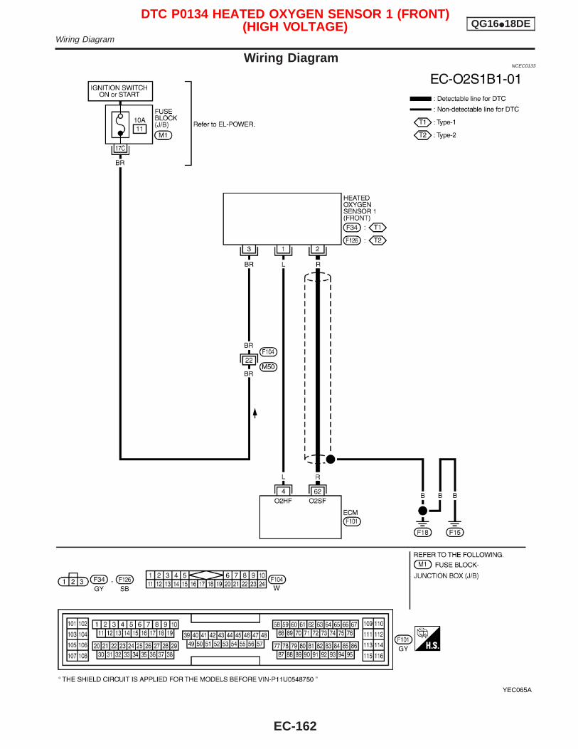
Wiring DiagramNCEC0133
YEC065A
DTC P0134 HEATED OXYGEN SENSOR 1 (FRONT)(HIGH VOLTAGE) QG16I18DE
Wiring Diagram
EC-162
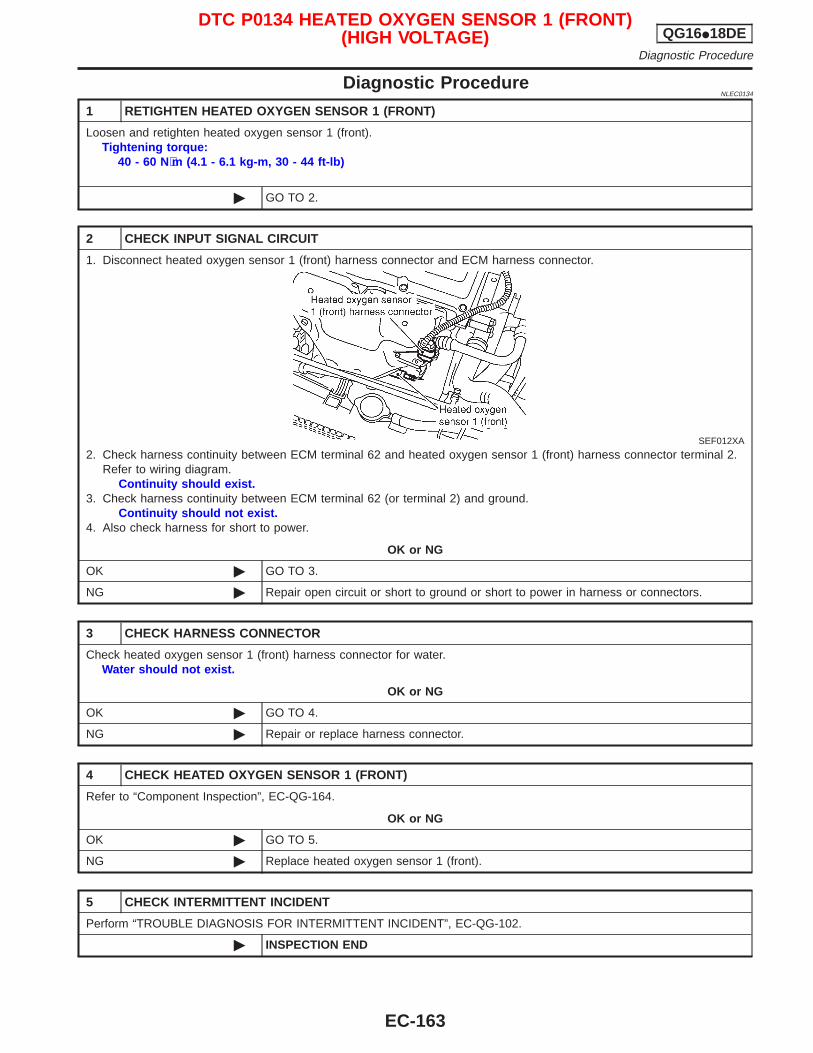
Diagnostic ProcedureNLEC0134
1 RETIGHTEN HEATED OXYGEN SENSOR 1 (FRONT)
Loosen and retighten heated oxygen sensor 1 (front).Tightening torque:
40 - 60 N⋅m (4.1 - 6.1 kg-m, 30 - 44 ft-lb)
© GO TO 2.
2 CHECK INPUT SIGNAL CIRCUIT
1. Disconnect heated oxygen sensor 1 (front) harness connector and ECM harness connector.
SEF012XA
2. Check harness continuity between ECM terminal 62 and heated oxygen sensor 1 (front) harness connector terminal 2.Refer to wiring diagram.
Continuity should exist.3. Check harness continuity between ECM terminal 62 (or terminal 2) and ground.
Continuity should not exist.4. Also check harness for short to power.
OK or NG
OK © GO TO 3.
NG © Repair open circuit or short to ground or short to power in harness or connectors.
3 CHECK HARNESS CONNECTOR
Check heated oxygen sensor 1 (front) harness connector for water.Water should not exist.
OK or NG
OK © GO TO 4.
NG © Repair or replace harness connector.
4 CHECK HEATED OXYGEN SENSOR 1 (FRONT)
Refer to “Component Inspection”, EC-QG-164.
OK or NG
OK © GO TO 5.
NG © Replace heated oxygen sensor 1 (front).
5 CHECK INTERMITTENT INCIDENT
Perform “TROUBLE DIAGNOSIS FOR INTERMITTENT INCIDENT”, EC-QG-102.
© INSPECTION END
DTC P0134 HEATED OXYGEN SENSOR 1 (FRONT)(HIGH VOLTAGE) QG16I18DE
Diagnostic Procedure
EC-163
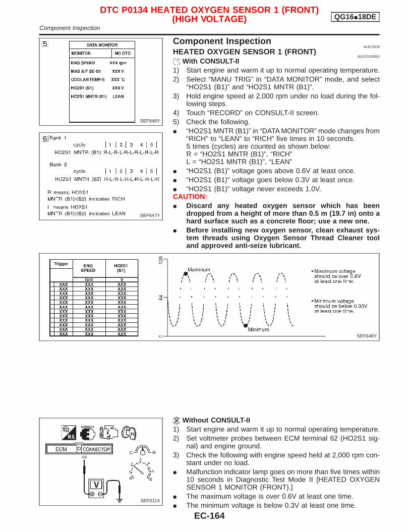
Component InspectionNLEC0135
HEATED OXYGEN SENSOR 1 (FRONT)NLEC0135S01
With CONSULT-II1) Start engine and warm it up to normal operating temperature.2) Select “MANU TRIG” in “DATA MONITOR” mode, and select
“HO2S1 (B1)” and “HO2S1 MNTR (B1)”.3) Hold engine speed at 2,000 rpm under no load during the fol-
lowing steps.4) Touch “RECORD” on CONSULT-II screen.5) Check the following.I “HO2S1 MNTR (B1)” in “DATA MONITOR” mode changes from
“RICH” to “LEAN” to “RICH” five times in 10 seconds.5 times (cycles) are counted as shown below:R = “HO2S1 MNTR (B1)”, “RICH”L = “HO2S1 MNTR (B1)”, “LEAN”
I “HO2S1 (B1)” voltage goes above 0.6V at least once.I “HO2S1 (B1)” voltage goes below 0.3V at least once.I “HO2S1 (B1)” voltage never exceeds 1.0V.CAUTION:I Discard any heated oxygen sensor which has been
dropped from a height of more than 0.5 m (19.7 in) onto ahard surface such as a concrete floor; use a new one.
I Before installing new oxygen sensor, clean exhaust sys-tem threads using Oxygen Sensor Thread Cleaner tooland approved anti-seize lubricant.
Without CONSULT-II1) Start engine and warm it up to normal operating temperature.2) Set voltmeter probes between ECM terminal 62 (HO2S1 sig-
nal) and engine ground.3) Check the following with engine speed held at 2,000 rpm con-
stant under no load.I Malfunction indicator lamp goes on more than five times within
10 seconds in Diagnostic Test Mode II [HEATED OXYGENSENSOR 1 MONITOR (FRONT).]
I The maximum voltage is over 0.6V at least one time.I The minimum voltage is below 0.3V at least one time.
SEF646Y
SEF647Y
SEF648Y
SEF011X
DTC P0134 HEATED OXYGEN SENSOR 1 (FRONT)(HIGH VOLTAGE) QG16I18DE
Component Inspection
EC-164
I The voltage never exceeds 1.0V.CAUTION:I Discard any heated oxygen sensor which has been
dropped from a height of more than 0.5 m (19.7 in) onto ahard surface such as a concrete floor; use a new one.
I Before installing new oxygen sensor, clean exhaust sys-tem threads using Oxygen Sensor Thread Cleaner tooland approved anti-seize lubricant.
DTC P0134 HEATED OXYGEN SENSOR 1 (FRONT)(HIGH VOLTAGE) QG16I18DE
Component Inspection (Cont’d)
EC-165
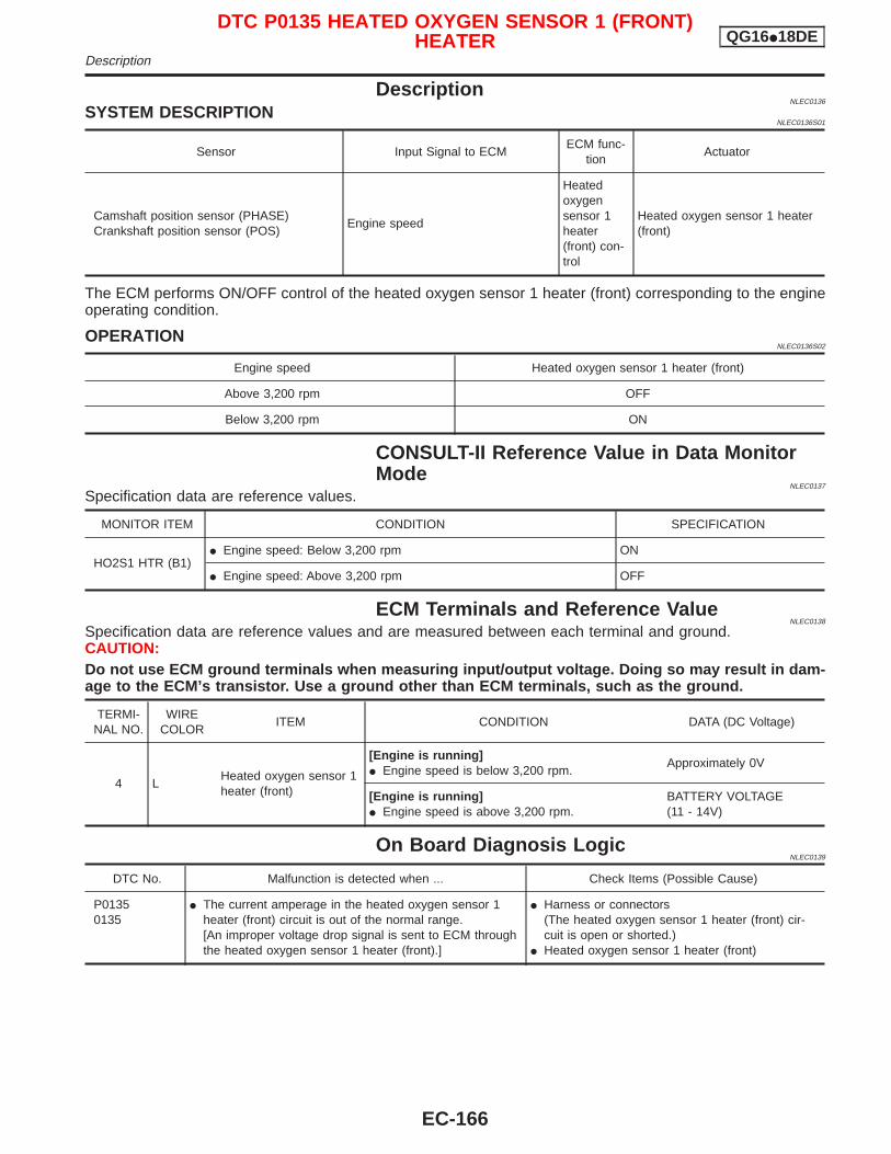
DescriptionNLEC0136
SYSTEM DESCRIPTIONNLEC0136S01
Sensor Input Signal to ECMECM func-
tionActuator
Camshaft position sensor (PHASE)Crankshaft position sensor (POS)
Engine speed
Heatedoxygensensor 1heater(front) con-trol
Heated oxygen sensor 1 heater(front)
The ECM performs ON/OFF control of the heated oxygen sensor 1 heater (front) corresponding to the engineoperating condition.
OPERATIONNLEC0136S02
Engine speed Heated oxygen sensor 1 heater (front)
Above 3,200 rpm OFF
Below 3,200 rpm ON
CONSULT-II Reference Value in Data MonitorMode
NLEC0137
Specification data are reference values.
MONITOR ITEM CONDITION SPECIFICATION
HO2S1 HTR (B1)I Engine speed: Below 3,200 rpm ON
I Engine speed: Above 3,200 rpm OFF
ECM Terminals and Reference ValueNLEC0138
Specification data are reference values and are measured between each terminal and ground.CAUTION:Do not use ECM ground terminals when measuring input/output voltage. Doing so may result in dam-age to the ECM’s transistor. Use a ground other than ECM terminals, such as the ground.
TERMI-NAL NO.
WIRECOLOR
ITEM CONDITION DATA (DC Voltage)
4 LHeated oxygen sensor 1heater (front)
[Engine is running]I Engine speed is below 3,200 rpm.
Approximately 0V
[Engine is running]I Engine speed is above 3,200 rpm.
BATTERY VOLTAGE(11 - 14V)
On Board Diagnosis LogicNLEC0139
DTC No. Malfunction is detected when ... Check Items (Possible Cause)
P01350135
I The current amperage in the heated oxygen sensor 1heater (front) circuit is out of the normal range.[An improper voltage drop signal is sent to ECM throughthe heated oxygen sensor 1 heater (front).]
I Harness or connectors(The heated oxygen sensor 1 heater (front) cir-cuit is open or shorted.)
I Heated oxygen sensor 1 heater (front)
DTC P0135 HEATED OXYGEN SENSOR 1 (FRONT)HEATER QG16I18DE
Description
EC-166
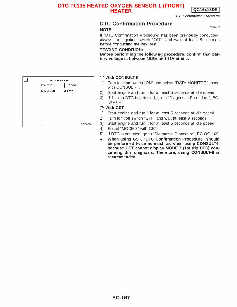
DTC Confirmation ProcedureNLEC0140
NOTE:If “DTC Confirmation Procedure” has been previously conducted,always turn ignition switch “OFF” and wait at least 9 secondsbefore conducting the next test.TESTING CONDITION:Before performing the following procedure, confirm that bat-tery voltage is between 10.5V and 16V at idle.
With CONSULT-II1) Turn ignition switch “ON” and select “DATA MONITOR” mode
with CONSULT-II.2) Start engine and run it for at least 5 seconds at idle speed.3) If 1st trip DTC is detected, go to “Diagnostic Procedure”, EC-
QG-169.With GST
1) Start engine and run it for at least 5 seconds at idle speed.2) Turn ignition switch “OFF” and wait at least 9 seconds.3) Start engine and run it for at least 5 seconds at idle speed.4) Select “MODE 3” with GST.5) If DTC is detected, go to “Diagnostic Procedure”, EC-QG-169.I When using GST, “DTC Confirmation Procedure” should
be performed twice as much as when using CONSULT-IIbecause GST cannot display MODE 7 (1st trip DTC) con-cerning this diagnosis. Therefore, using CONSULT-II isrecommended.
SEF058Y
DTC P0135 HEATED OXYGEN SENSOR 1 (FRONT)HEATER QG16I18DE
DTC Confirmation Procedure
EC-167
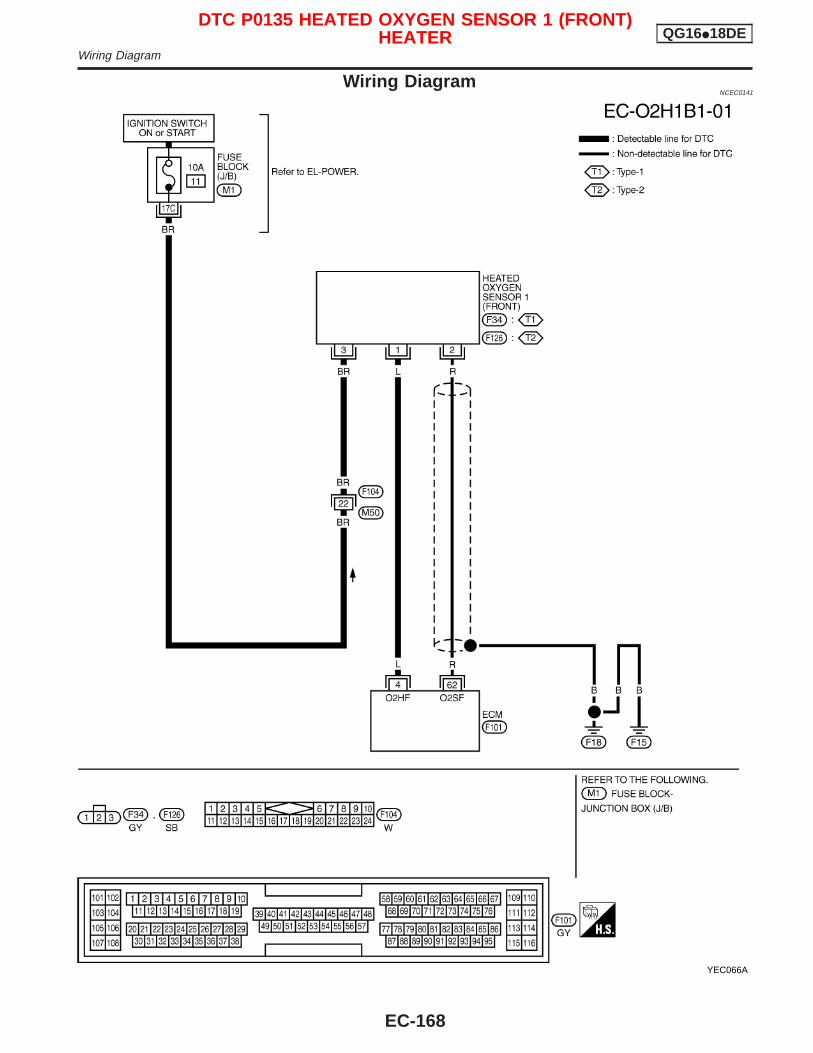
Wiring DiagramNCEC0141
YEC066A
DTC P0135 HEATED OXYGEN SENSOR 1 (FRONT)HEATER QG16I18DE
Wiring Diagram
EC-168
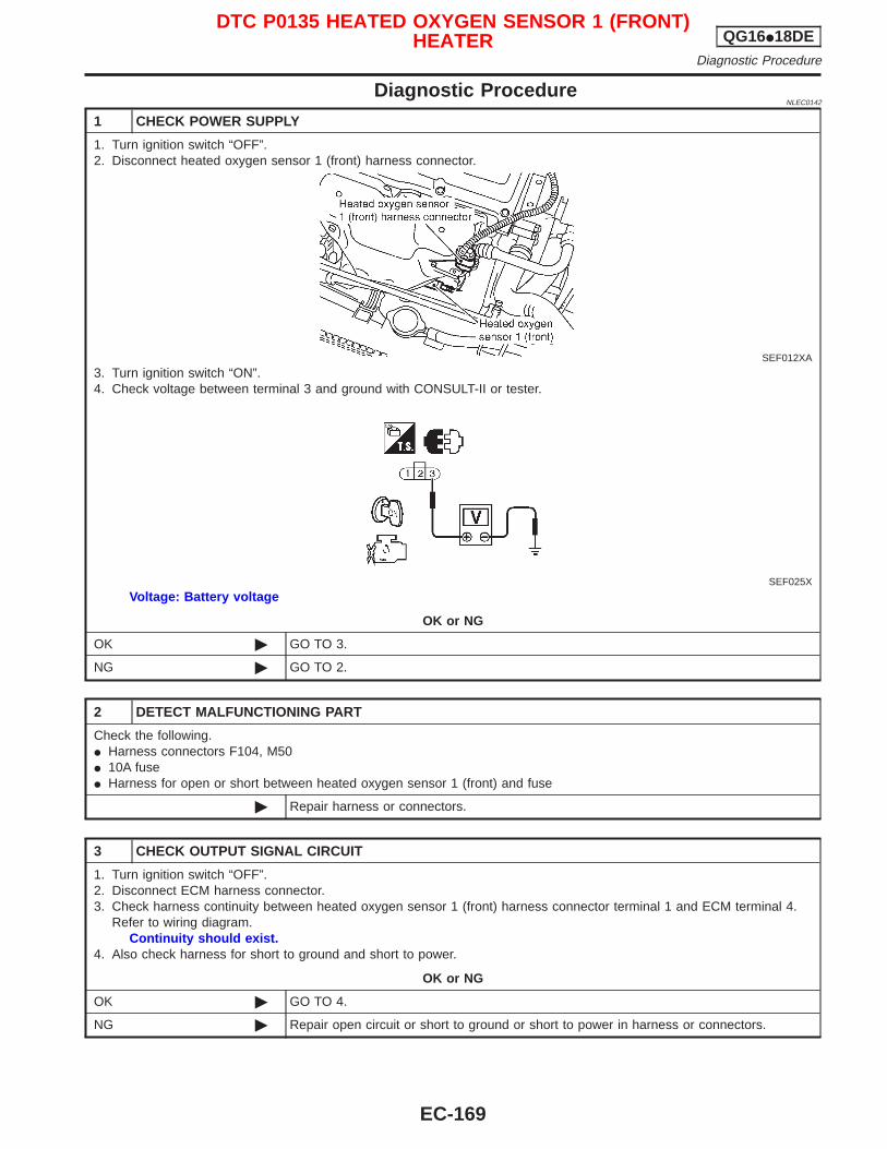
Diagnostic ProcedureNLEC0142
1 CHECK POWER SUPPLY
1. Turn ignition switch “OFF”.2. Disconnect heated oxygen sensor 1 (front) harness connector.
SEF012XA
3. Turn ignition switch “ON”.4. Check voltage between terminal 3 and ground with CONSULT-II or tester.
SEF025X
Voltage: Battery voltage
OK or NG
OK © GO TO 3.
NG © GO TO 2.
2 DETECT MALFUNCTIONING PART
Check the following.I Harness connectors F104, M50I 10A fuseI Harness for open or short between heated oxygen sensor 1 (front) and fuse
© Repair harness or connectors.
3 CHECK OUTPUT SIGNAL CIRCUIT
1. Turn ignition switch “OFF”.2. Disconnect ECM harness connector.3. Check harness continuity between heated oxygen sensor 1 (front) harness connector terminal 1 and ECM terminal 4.
Refer to wiring diagram.Continuity should exist.
4. Also check harness for short to ground and short to power.
OK or NG
OK © GO TO 4.
NG © Repair open circuit or short to ground or short to power in harness or connectors.
DTC P0135 HEATED OXYGEN SENSOR 1 (FRONT)HEATER QG16I18DE
Diagnostic Procedure
EC-169
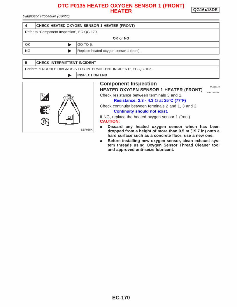
4 CHECK HEATED OXYGEN SENSOR 1 HEATER (FRONT)
Refer to “Component Inspection”, EC-QG-170.
OK or NG
OK © GO TO 5.
NG © Replace heated oxygen sensor 1 (front).
5 CHECK INTERMITTENT INCIDENT
Perform “TROUBLE DIAGNOSIS FOR INTERMITTENT INCIDENT”, EC-QG-102.
© INSPECTION END
Component InspectionNLEC0143
HEATED OXYGEN SENSOR 1 HEATER (FRONT)NLEC0143S01
Check resistance between terminals 3 and 1.Resistance: 2.3 - 4.3 Ω at 25°C (77°F)
Check continuity between terminals 2 and 1, 3 and 2.Continuity should not exist.
If NG, replace the heated oxygen sensor 1 (front).CAUTION:I Discard any heated oxygen sensor which has been
dropped from a height of more than 0.5 m (19.7 in) onto ahard surface such as a concrete floor; use a new one.
I Before installing new oxygen sensor, clean exhaust sys-tem threads using Oxygen Sensor Thread Cleaner tooland approved anti-seize lubricant.
SEF935X
DTC P0135 HEATED OXYGEN SENSOR 1 (FRONT)HEATER QG16I18DE
Diagnostic Procedure (Cont’d)
EC-170
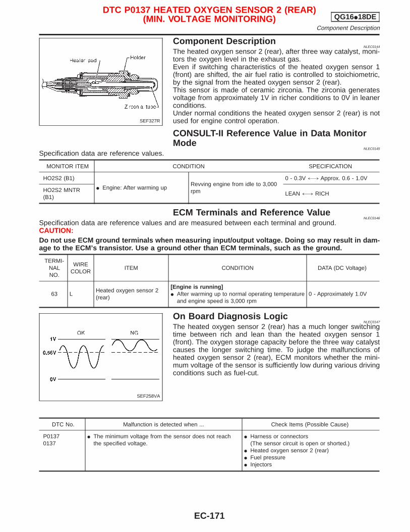
Component DescriptionNLEC0144
The heated oxygen sensor 2 (rear), after three way catalyst, moni-tors the oxygen level in the exhaust gas.Even if switching characteristics of the heated oxygen sensor 1(front) are shifted, the air fuel ratio is controlled to stoichiometric,by the signal from the heated oxygen sensor 2 (rear).This sensor is made of ceramic zirconia. The zirconia generatesvoltage from approximately 1V in richer conditions to 0V in leanerconditions.Under normal conditions the heated oxygen sensor 2 (rear) is notused for engine control operation.
CONSULT-II Reference Value in Data MonitorMode
NLEC0145
Specification data are reference values.
MONITOR ITEM CONDITION SPECIFICATION
HO2S2 (B1)
I Engine: After warming upRevving engine from idle to 3,000rpm
0 - 0.3V +, Approx. 0.6 - 1.0V
HO2S2 MNTR(B1)
LEAN +, RICH
ECM Terminals and Reference ValueNLEC0146
Specification data are reference values and are measured between each terminal and ground.CAUTION:Do not use ECM ground terminals when measuring input/output voltage. Doing so may result in dam-age to the ECM’s transistor. Use a ground other than ECM terminals, such as the ground.
TERMI-NALNO.
WIRECOLOR
ITEM CONDITION DATA (DC Voltage)
63 LHeated oxygen sensor 2(rear)
[Engine is running]I After warming up to normal operating temperature
and engine speed is 3,000 rpm0 - Approximately 1.0V
On Board Diagnosis LogicNLEC0147
The heated oxygen sensor 2 (rear) has a much longer switchingtime between rich and lean than the heated oxygen sensor 1(front). The oxygen storage capacity before the three way catalystcauses the longer switching time. To judge the malfunctions ofheated oxygen sensor 2 (rear), ECM monitors whether the mini-mum voltage of the sensor is sufficiently low during various drivingconditions such as fuel-cut.
DTC No. Malfunction is detected when ... Check Items (Possible Cause)
P01370137
I The minimum voltage from the sensor does not reachthe specified voltage.
I Harness or connectors(The sensor circuit is open or shorted.)
I Heated oxygen sensor 2 (rear)I Fuel pressureI Injectors
SEF327R
SEF258VA
DTC P0137 HEATED OXYGEN SENSOR 2 (REAR)(MIN. VOLTAGE MONITORING) QG16I18DE
Component Description
EC-171
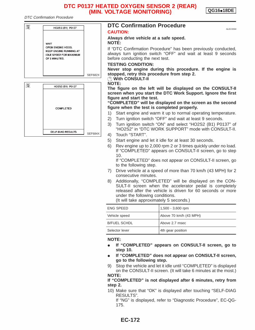
DTC Confirmation ProcedureNLEC0594
CAUTION:Always drive vehicle at a safe speed.NOTE:If “DTC Confirmation Procedure” has been previously conducted,always turn ignition switch “OFF” and wait at least 9 secondsbefore conducting the next test.TESTING CONDITION:Never stop engine during this procedure. If the engine isstopped, retry this procedure from step 2.
With CONSULT-IINOTE:The figure on the left will be displayed on the CONSULT-IIscreen when you start the DTC Work Support. Ignore the firstfigure and start the test.“COMPLETED” will be displayed on the screen as the secondfigure when the test is completed properly.1) Start engine and warm it up to normal operating temperature.2) Turn ignition switch “OFF” and wait at least 9 seconds.3) Turn ignition switch “ON” and select “HO2S2 (B1) P0137” of
“HO2S2” in “DTC WORK SUPPORT” mode with CONSULT-II.4) Touch “START”.5) Start engine and let it idle for at least 30 seconds.6) Rev engine up to 2,000 rpm 2 or 3 times quickly under no load.
If “COMPLETED” appears on CONSULT-II screen, go to step10.If “COMPLETED” does not appear on CONSULT-II screen, goto the following step.
7) Drive vehicle at a speed of more than 70 km/h (43 MPH) for 2consecutive minutes.
8) Additionally, “COMPLETED” will be displayed on the CON-SULT-II screen when the accelerator pedal is completelyreleased after the vehicle is driven for 60 seconds or moreunder the following conditions.(It will take approximately 5 seconds.)
ENG SPEED 1,500 - 3,600 rpm
Vehicle speed Above 70 km/h (43 MPH)
B/FUEL SCHDL Above 2.7 msec
Selector lever 4th gear position
NOTE:I If “COMPLETED” appears on CONSULT-II screen, go to
step 10.I If “COMPLETED” does not appear on CONSULT-II screen,
go to the following step.9) Stop the vehicle and let it idle until “COMPLETED” is displayed
on the CONSULT-II screen. (It will take 6 minutes at the most.)NOTE:If “COMPLETED” is not displayed after 6 minutes, retry fromstep 2.10) Make sure that “OK” is displayed after touching “SELF-DIAG
RESULTS”.If “NG” is displayed, refer to “Diagnostic Procedure”, EC-QG-175.
SEF682X
SEF684X
DTC P0137 HEATED OXYGEN SENSOR 2 (REAR)(MIN. VOLTAGE MONITORING) QG16I18DE
DTC Confirmation Procedure
EC-172
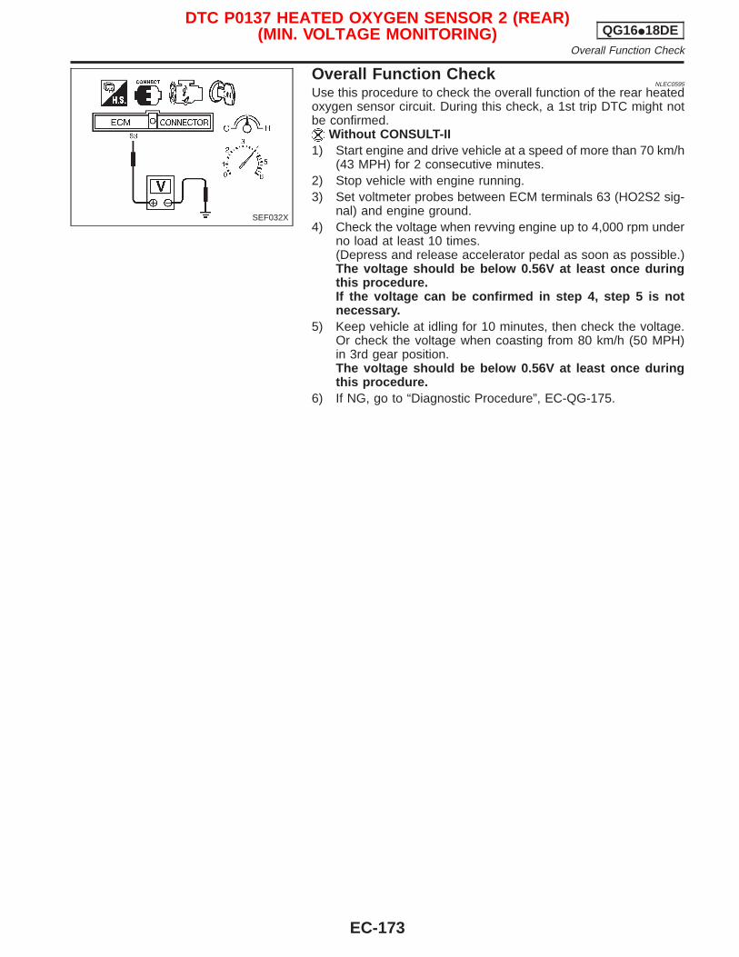
Overall Function CheckNLEC0595
Use this procedure to check the overall function of the rear heatedoxygen sensor circuit. During this check, a 1st trip DTC might notbe confirmed.
Without CONSULT-II1) Start engine and drive vehicle at a speed of more than 70 km/h
(43 MPH) for 2 consecutive minutes.2) Stop vehicle with engine running.3) Set voltmeter probes between ECM terminals 63 (HO2S2 sig-
nal) and engine ground.4) Check the voltage when revving engine up to 4,000 rpm under
no load at least 10 times.(Depress and release accelerator pedal as soon as possible.)The voltage should be below 0.56V at least once duringthis procedure.If the voltage can be confirmed in step 4, step 5 is notnecessary.
5) Keep vehicle at idling for 10 minutes, then check the voltage.Or check the voltage when coasting from 80 km/h (50 MPH)in 3rd gear position.The voltage should be below 0.56V at least once duringthis procedure.
6) If NG, go to “Diagnostic Procedure”, EC-QG-175.
SEF032X
DTC P0137 HEATED OXYGEN SENSOR 2 (REAR)(MIN. VOLTAGE MONITORING) QG16I18DE
Overall Function Check
EC-173
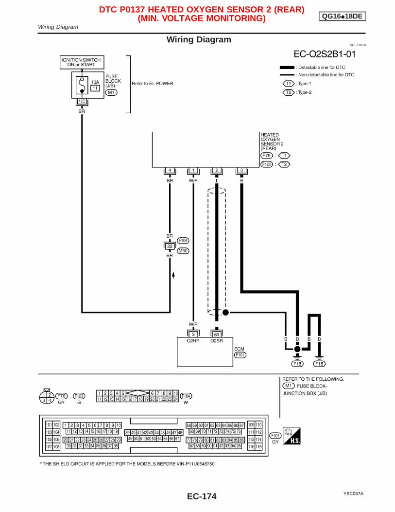
Wiring DiagramNCEC0150
YEC067A
DTC P0137 HEATED OXYGEN SENSOR 2 (REAR)(MIN. VOLTAGE MONITORING) QG16I18DE
Wiring Diagram
EC-174
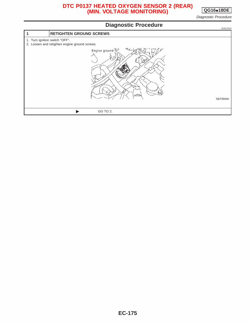
Diagnostic ProcedureNCEC0151
1 RETIGHTEN GROUND SCREWS
1. Turn ignition switch “OFF”.2. Loosen and retighten engine ground screws.
SEF994W
© GO TO 2.
DTC P0137 HEATED OXYGEN SENSOR 2 (REAR)(MIN. VOLTAGE MONITORING) QG16I18DE
Diagnostic Procedure
EC-175
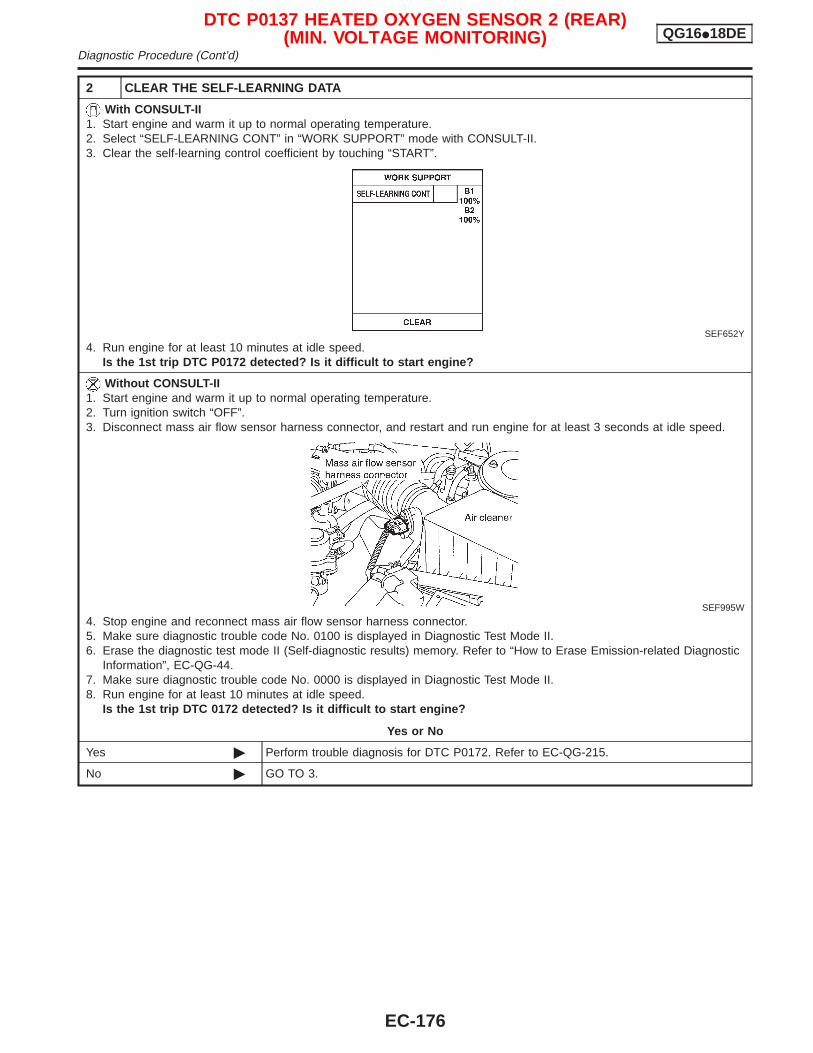
2 CLEAR THE SELF-LEARNING DATA
With CONSULT-II1. Start engine and warm it up to normal operating temperature.2. Select “SELF-LEARNING CONT” in “WORK SUPPORT” mode with CONSULT-II.3. Clear the self-learning control coefficient by touching “START”.
SEF652Y
4. Run engine for at least 10 minutes at idle speed.Is the 1st trip DTC P0172 detected? Is it difficult to start engine?
Without CONSULT-II1. Start engine and warm it up to normal operating temperature.2. Turn ignition switch “OFF”.3. Disconnect mass air flow sensor harness connector, and restart and run engine for at least 3 seconds at idle speed.
SEF995W
4. Stop engine and reconnect mass air flow sensor harness connector.5. Make sure diagnostic trouble code No. 0100 is displayed in Diagnostic Test Mode II.6. Erase the diagnostic test mode II (Self-diagnostic results) memory. Refer to “How to Erase Emission-related Diagnostic
Information”, EC-QG-44.7. Make sure diagnostic trouble code No. 0000 is displayed in Diagnostic Test Mode II.8. Run engine for at least 10 minutes at idle speed.
Is the 1st trip DTC 0172 detected? Is it difficult to start engine?
Yes or No
Yes © Perform trouble diagnosis for DTC P0172. Refer to EC-QG-215.
No © GO TO 3.
DTC P0137 HEATED OXYGEN SENSOR 2 (REAR)(MIN. VOLTAGE MONITORING) QG16I18DE
Diagnostic Procedure (Cont’d)
EC-176
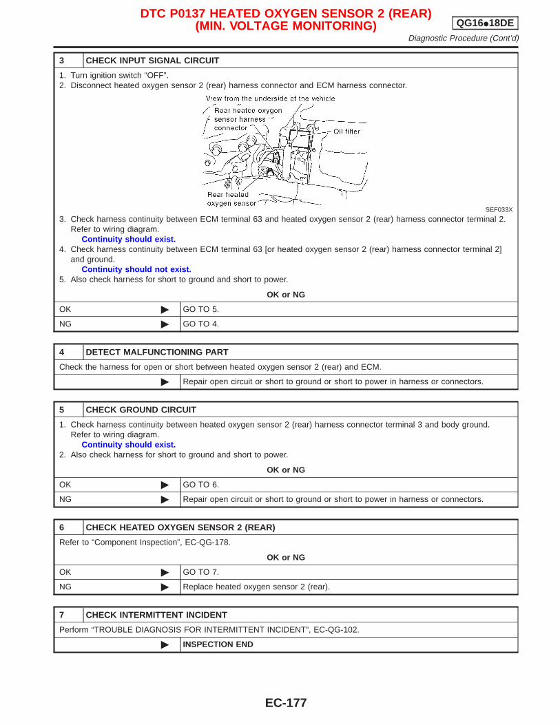
3 CHECK INPUT SIGNAL CIRCUIT
1. Turn ignition switch “OFF”.2. Disconnect heated oxygen sensor 2 (rear) harness connector and ECM harness connector.
SEF033X
3. Check harness continuity between ECM terminal 63 and heated oxygen sensor 2 (rear) harness connector terminal 2.Refer to wiring diagram.
Continuity should exist.4. Check harness continuity between ECM terminal 63 [or heated oxygen sensor 2 (rear) harness connector terminal 2]
and ground.Continuity should not exist.
5. Also check harness for short to ground and short to power.
OK or NG
OK © GO TO 5.
NG © GO TO 4.
4 DETECT MALFUNCTIONING PART
Check the harness for open or short between heated oxygen sensor 2 (rear) and ECM.
© Repair open circuit or short to ground or short to power in harness or connectors.
5 CHECK GROUND CIRCUIT
1. Check harness continuity between heated oxygen sensor 2 (rear) harness connector terminal 3 and body ground.Refer to wiring diagram.
Continuity should exist.2. Also check harness for short to ground and short to power.
OK or NG
OK © GO TO 6.
NG © Repair open circuit or short to ground or short to power in harness or connectors.
6 CHECK HEATED OXYGEN SENSOR 2 (REAR)
Refer to “Component Inspection”, EC-QG-178.
OK or NG
OK © GO TO 7.
NG © Replace heated oxygen sensor 2 (rear).
7 CHECK INTERMITTENT INCIDENT
Perform “TROUBLE DIAGNOSIS FOR INTERMITTENT INCIDENT”, EC-QG-102.
© INSPECTION END
DTC P0137 HEATED OXYGEN SENSOR 2 (REAR)(MIN. VOLTAGE MONITORING) QG16I18DE
Diagnostic Procedure (Cont’d)
EC-177
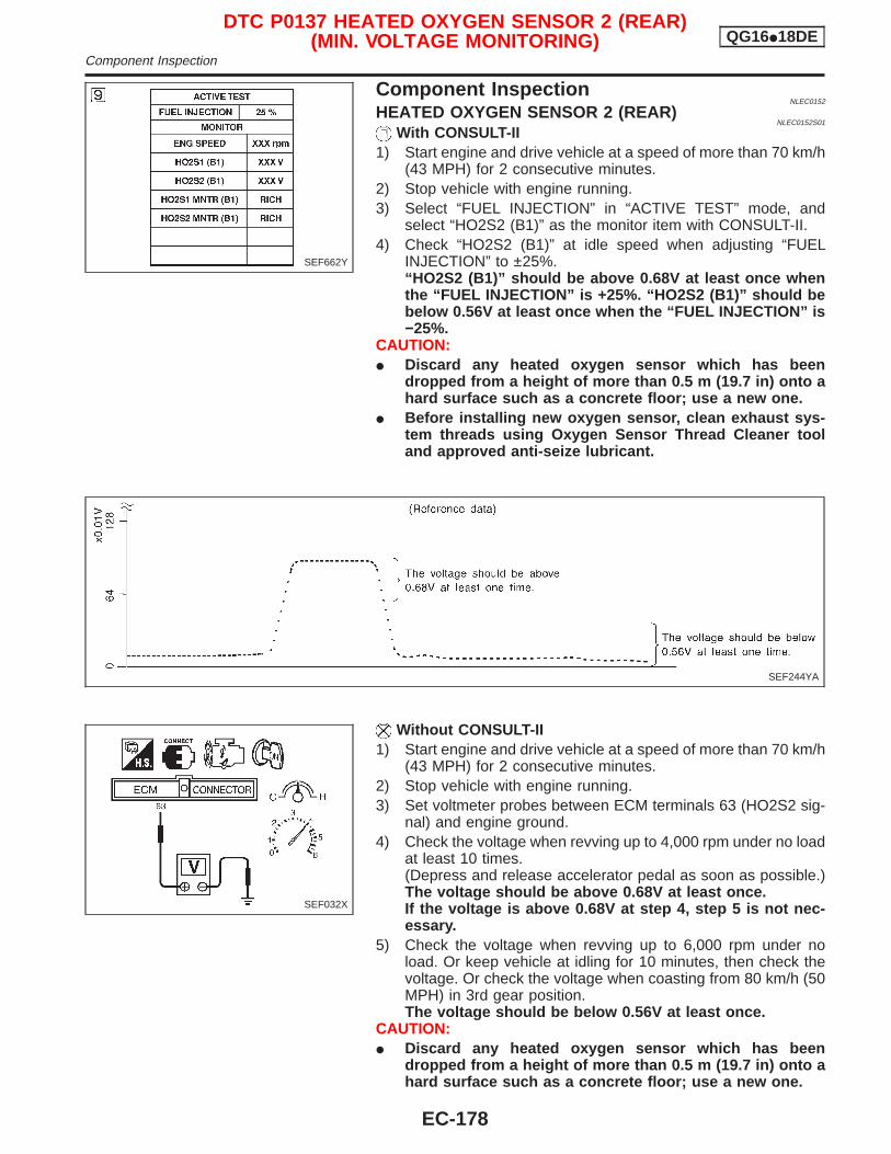
Component InspectionNLEC0152
HEATED OXYGEN SENSOR 2 (REAR)NLEC0152S01
With CONSULT-II1) Start engine and drive vehicle at a speed of more than 70 km/h
(43 MPH) for 2 consecutive minutes.2) Stop vehicle with engine running.3) Select “FUEL INJECTION” in “ACTIVE TEST” mode, and
select “HO2S2 (B1)” as the monitor item with CONSULT-II.4) Check “HO2S2 (B1)” at idle speed when adjusting “FUEL
INJECTION” to ±25%.“HO2S2 (B1)” should be above 0.68V at least once whenthe “FUEL INJECTION” is +25%. “HO2S2 (B1)” should bebelow 0.56V at least once when the “FUEL INJECTION” is−25%.
CAUTION:I Discard any heated oxygen sensor which has been
dropped from a height of more than 0.5 m (19.7 in) onto ahard surface such as a concrete floor; use a new one.
I Before installing new oxygen sensor, clean exhaust sys-tem threads using Oxygen Sensor Thread Cleaner tooland approved anti-seize lubricant.
Without CONSULT-II1) Start engine and drive vehicle at a speed of more than 70 km/h
(43 MPH) for 2 consecutive minutes.2) Stop vehicle with engine running.3) Set voltmeter probes between ECM terminals 63 (HO2S2 sig-
nal) and engine ground.4) Check the voltage when revving up to 4,000 rpm under no load
at least 10 times.(Depress and release accelerator pedal as soon as possible.)The voltage should be above 0.68V at least once.If the voltage is above 0.68V at step 4, step 5 is not nec-essary.
5) Check the voltage when revving up to 6,000 rpm under noload. Or keep vehicle at idling for 10 minutes, then check thevoltage. Or check the voltage when coasting from 80 km/h (50MPH) in 3rd gear position.The voltage should be below 0.56V at least once.
CAUTION:I Discard any heated oxygen sensor which has been
dropped from a height of more than 0.5 m (19.7 in) onto ahard surface such as a concrete floor; use a new one.
SEF662Y
SEF244YA
SEF032X
DTC P0137 HEATED OXYGEN SENSOR 2 (REAR)(MIN. VOLTAGE MONITORING) QG16I18DE
Component Inspection
EC-178

I Before installing new oxygen sensor, clean exhaust sys-tem threads using Oxygen Sensor Thread Cleaner tooland approved anti-seize lubricant.
DTC P0137 HEATED OXYGEN SENSOR 2 (REAR)(MIN. VOLTAGE MONITORING) QG16I18DE
Component Inspection (Cont’d)
EC-179
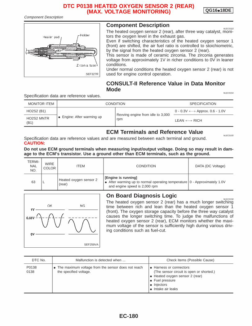
Component DescriptionNLEC0153
The heated oxygen sensor 2 (rear), after three way catalyst, moni-tors the oxygen level in the exhaust gas.Even if switching characteristics of the heated oxygen sensor 1(front) are shifted, the air fuel ratio is controlled to stoichiometric,by the signal from the heated oxygen sensor 2 (rear).This sensor is made of ceramic zirconia. The zirconia generatesvoltage from approximately 1V in richer conditions to 0V in leanerconditions.Under normal conditions the heated oxygen sensor 2 (rear) is notused for engine control operation.
CONSULT-II Reference Value in Data MonitorMode
NLEC0154
Specification data are reference values.
MONITOR ITEM CONDITION SPECIFICATION
HO2S2 (B1)
I Engine: After warming upRevving engine from idle to 3,000rpm
0 - 0.3V +, Approx. 0.6 - 1.0V
HO2S2 MNTR(B1)
LEAN +, RICH
ECM Terminals and Reference ValueNLEC0155
Specification data are reference values and are measured between each terminal and ground.CAUTION:Do not use ECM ground terminals when measuring input/output voltage. Doing so may result in dam-age to the ECM’s transistor. Use a ground other than ECM terminals, such as the ground.
TERMI-NALNO.
WIRECOLOR
ITEM CONDITION DATA (DC Voltage)
63 LHeated oxygen sensor 2(rear)
[Engine is running]I After warming up to normal operating temperature
and engine speed is 2,000 rpm0 - Approximately 1.0V
On Board Diagnosis LogicNLEC0156
The heated oxygen sensor 2 (rear) has a much longer switchingtime between rich and lean than the heated oxygen sensor 1(front). The oxygen storage capacity before the three way catalystcauses the longer switching time. To judge the malfunctions ofheated oxygen sensor 2 (rear), ECM monitors whether the maxi-mum voltage of the sensor is sufficiently high during various driv-ing conditions such as fuel-cut.
DTC No. Malfunction is detected when ... Check Items (Possible Cause)
P01380138
I The maximum voltage from the sensor does not reachthe specified voltage.
I Harness or connectors(The sensor circuit is open or shorted.)
I Heated oxygen sensor 2 (rear)I Fuel pressureI InjectorsI Intake air leaks
SEF327R
SEF259VA
DTC P0138 HEATED OXYGEN SENSOR 2 (REAR)(MAX. VOLTAGE MONITORING) QG16I18DE
Component Description
EC-180
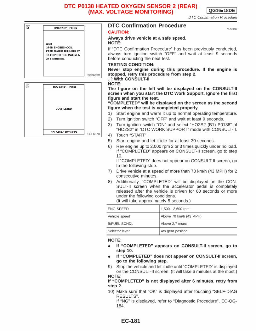
DTC Confirmation ProcedureNLEC0596
CAUTION:Always drive vehicle at a safe speed.NOTE:If “DTC Confirmation Procedure” has been previously conducted,always turn ignition switch “OFF” and wait at least 9 secondsbefore conducting the next test.TESTING CONDITION:Never stop engine during this procedure. If the engine isstopped, retry this procedure from step 2.
With CONSULT-IINOTE:The figure on the left will be displayed on the CONSULT-IIscreen when you start the DTC Work Support. Ignore the firstfigure and start the test.“COMPLETED” will be displayed on the screen as the secondfigure when the test is completed properly.1) Start engine and warm it up to normal operating temperature.2) Turn ignition switch “OFF” and wait at least 9 seconds.3) Turn ignition switch “ON” and select “HO2S2 (B1) P0138” of
“HO2S2” in “DTC WORK SUPPORT” mode with CONSULT-II.4) Touch “START”.5) Start engine and let it idle for at least 30 seconds.6) Rev engine up to 2,000 rpm 2 or 3 times quickly under no load.
If “COMPLETED” appears on CONSULT-II screen, go to step10.If “COMPLETED” does not appear on CONSULT-II screen, goto the following step.
7) Drive vehicle at a speed of more than 70 km/h (43 MPH) for 2consecutive minutes.
8) Additionally, “COMPLETED” will be displayed on the CON-SULT-II screen when the accelerator pedal is completelyreleased after the vehicle is driven for 60 seconds or moreunder the following conditions.(It will take approximately 5 seconds.)
ENG SPEED 1,500 - 3,600 rpm
Vehicle speed Above 70 km/h (43 MPH)
B/FUEL SCHDL Above 2.7 msec
Selector lever 4th gear position
NOTE:I If “COMPLETED” appears on CONSULT-II screen, go to
step 10.I If “COMPLETED” does not appear on CONSULT-II screen,
go to the following step.9) Stop the vehicle and let it idle until “COMPLETED” is displayed
on the CONSULT-II screen. (It will take 6 minutes at the most.)NOTE:If “COMPLETED” is not displayed after 6 minutes, retry fromstep 2.10) Make sure that “OK” is displayed after touching “SELF-DIAG
RESULTS”.If “NG” is displayed, refer to “Diagnostic Procedure”, EC-QG-184.
SEF685X
SEF687X
DTC P0138 HEATED OXYGEN SENSOR 2 (REAR)(MAX. VOLTAGE MONITORING) QG16I18DE
DTC Confirmation Procedure
EC-181
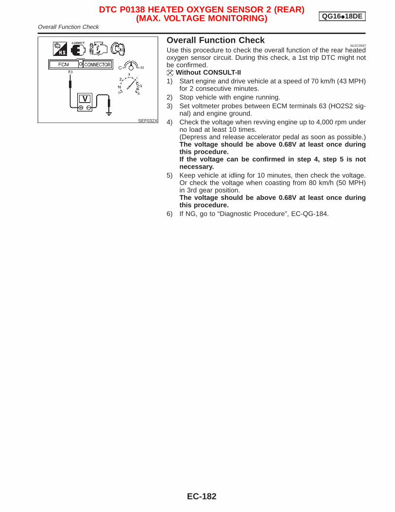
SEF032X
Overall Function CheckNLEC0597
Use this procedure to check the overall function of the rear heatedoxygen sensor circuit. During this check, a 1st trip DTC might notbe confirmed.
Without CONSULT-II1) Start engine and drive vehicle at a speed of 70 km/h (43 MPH)
for 2 consecutive minutes.2) Stop vehicle with engine running.3) Set voltmeter probes between ECM terminals 63 (HO2S2 sig-
nal) and engine ground.4) Check the voltage when revving engine up to 4,000 rpm under
no load at least 10 times.(Depress and release accelerator pedal as soon as possible.)The voltage should be above 0.68V at least once duringthis procedure.If the voltage can be confirmed in step 4, step 5 is notnecessary.
5) Keep vehicle at idling for 10 minutes, then check the voltage.Or check the voltage when coasting from 80 km/h (50 MPH)in 3rd gear position.The voltage should be above 0.68V at least once duringthis procedure.
6) If NG, go to “Diagnostic Procedure”, EC-QG-184.
DTC P0138 HEATED OXYGEN SENSOR 2 (REAR)(MAX. VOLTAGE MONITORING) QG16I18DE
Overall Function Check
EC-182
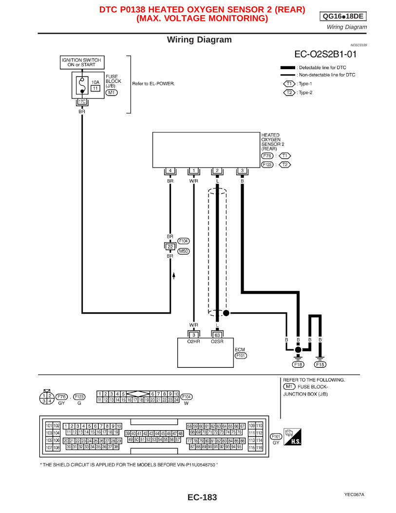
Wiring DiagramNCEC0159
YEC067A
DTC P0138 HEATED OXYGEN SENSOR 2 (REAR)(MAX. VOLTAGE MONITORING) QG16I18DE
Wiring Diagram
EC-183
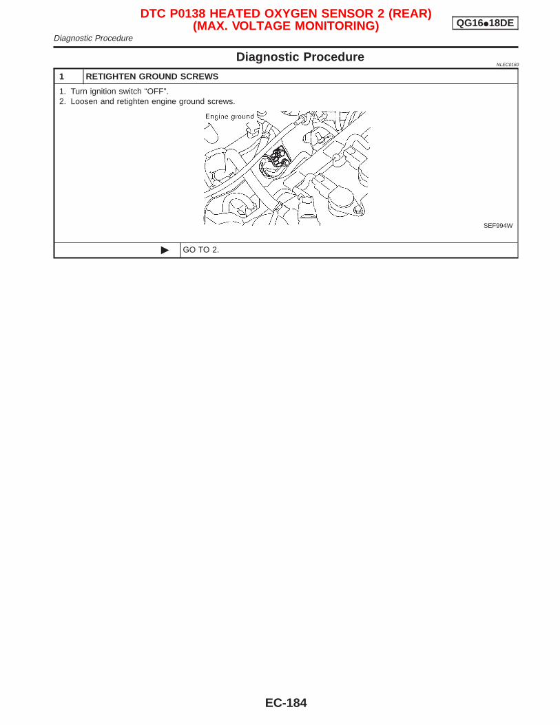
Diagnostic ProcedureNLEC0160
1 RETIGHTEN GROUND SCREWS
1. Turn ignition switch “OFF”.2. Loosen and retighten engine ground screws.
SEF994W
© GO TO 2.
DTC P0138 HEATED OXYGEN SENSOR 2 (REAR)(MAX. VOLTAGE MONITORING) QG16I18DE
Diagnostic Procedure
EC-184

2 CLEAR THE SELF-LEARNING DATA
With CONSULT-II1. Start engine and warm it up to normal operating temperature.2. Select “SELF-LEARNING CONT” in “WORK SUPPORT” mode with CONSULT-II.3. Clear the self-learning control coefficient by touching “START”.
SEF652Y
4. Run engine for at least 10 minutes at idle speed.Is the 1st trip DTC P0171 detected? Is it difficult to start engine?
Without CONSULT-II1. Start engine and warm it up to normal operating temperature.2. Turn ignition switch “OFF”.3. Disconnect mass air flow sensor harness connector, and restart and run engine for at least 3 seconds at idle speed.
SEF995W
4. Stop engine and reconnect mass air flow sensor harness connector.5. Make sure diagnostic trouble code No. 0100 is displayed in Diagnostic Test Mode II.6. Erase the diagnostic test mode II (Self-diagnostic results) memory. Refer to “How to Erase Emission-related Diagnostic
Information”, EC-QG-44.7. Make sure diagnostic trouble code No. 0000 is displayed in Diagnostic Test Mode II.8. Run engine for at least 10 minutes at idle speed.
Is the 1st trip DTC 0171 detected? Is it difficult to start engine?
Yes or No
Yes © Perform trouble diagnosis for DTC P0171. Refer to EC-QG-208.
No © GO TO 3.
DTC P0138 HEATED OXYGEN SENSOR 2 (REAR)(MAX. VOLTAGE MONITORING) QG16I18DE
Diagnostic Procedure (Cont’d)
EC-185
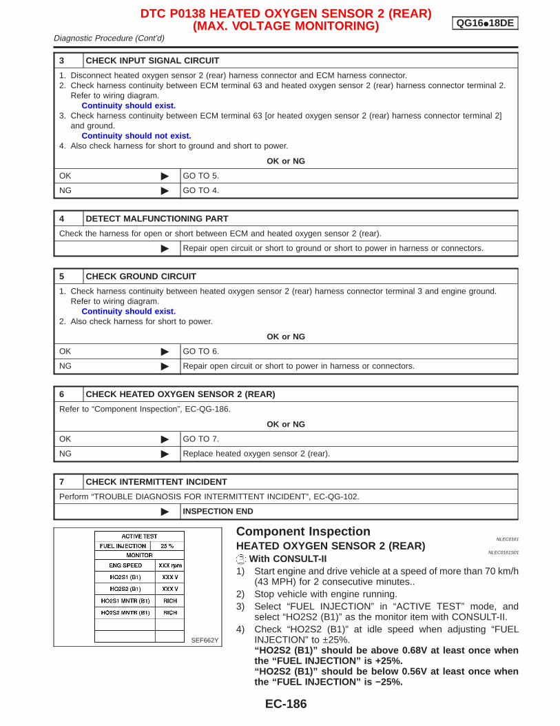
3 CHECK INPUT SIGNAL CIRCUIT
1. Disconnect heated oxygen sensor 2 (rear) harness connector and ECM harness connector.2. Check harness continuity between ECM terminal 63 and heated oxygen sensor 2 (rear) harness connector terminal 2.
Refer to wiring diagram.Continuity should exist.
3. Check harness continuity between ECM terminal 63 [or heated oxygen sensor 2 (rear) harness connector terminal 2]and ground.
Continuity should not exist.4. Also check harness for short to ground and short to power.
OK or NG
OK © GO TO 5.
NG © GO TO 4.
4 DETECT MALFUNCTIONING PART
Check the harness for open or short between ECM and heated oxygen sensor 2 (rear).
© Repair open circuit or short to ground or short to power in harness or connectors.
5 CHECK GROUND CIRCUIT
1. Check harness continuity between heated oxygen sensor 2 (rear) harness connector terminal 3 and engine ground.Refer to wiring diagram.
Continuity should exist.2. Also check harness for short to power.
OK or NG
OK © GO TO 6.
NG © Repair open circuit or short to power in harness or connectors.
6 CHECK HEATED OXYGEN SENSOR 2 (REAR)
Refer to “Component Inspection”, EC-QG-186.
OK or NG
OK © GO TO 7.
NG © Replace heated oxygen sensor 2 (rear).
7 CHECK INTERMITTENT INCIDENT
Perform “TROUBLE DIAGNOSIS FOR INTERMITTENT INCIDENT”, EC-QG-102.
© INSPECTION END
Component InspectionNLEC0161
HEATED OXYGEN SENSOR 2 (REAR)NLEC0161S01
With CONSULT-II1) Start engine and drive vehicle at a speed of more than 70 km/h
(43 MPH) for 2 consecutive minutes..2) Stop vehicle with engine running.3) Select “FUEL INJECTION” in “ACTIVE TEST” mode, and
select “HO2S2 (B1)” as the monitor item with CONSULT-II.4) Check “HO2S2 (B1)” at idle speed when adjusting “FUEL
INJECTION” to ±25%.“HO2S2 (B1)” should be above 0.68V at least once whenthe “FUEL INJECTION” is +25%.“HO2S2 (B1)” should be below 0.56V at least once whenthe “FUEL INJECTION” is −25%.
SEF662Y
DTC P0138 HEATED OXYGEN SENSOR 2 (REAR)(MAX. VOLTAGE MONITORING) QG16I18DE
Diagnostic Procedure (Cont’d)
EC-186
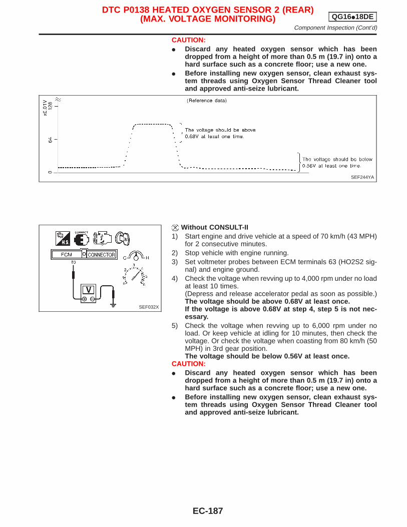
CAUTION:I Discard any heated oxygen sensor which has been
dropped from a height of more than 0.5 m (19.7 in) onto ahard surface such as a concrete floor; use a new one.
I Before installing new oxygen sensor, clean exhaust sys-tem threads using Oxygen Sensor Thread Cleaner tooland approved anti-seize lubricant.
Without CONSULT-II1) Start engine and drive vehicle at a speed of 70 km/h (43 MPH)
for 2 consecutive minutes.2) Stop vehicle with engine running.3) Set voltmeter probes between ECM terminals 63 (HO2S2 sig-
nal) and engine ground.4) Check the voltage when revving up to 4,000 rpm under no load
at least 10 times.(Depress and release accelerator pedal as soon as possible.)The voltage should be above 0.68V at least once.If the voltage is above 0.68V at step 4, step 5 is not nec-essary.
5) Check the voltage when revving up to 6,000 rpm under noload. Or keep vehicle at idling for 10 minutes, then check thevoltage. Or check the voltage when coasting from 80 km/h (50MPH) in 3rd gear position.The voltage should be below 0.56V at least once.
CAUTION:I Discard any heated oxygen sensor which has been
dropped from a height of more than 0.5 m (19.7 in) onto ahard surface such as a concrete floor; use a new one.
I Before installing new oxygen sensor, clean exhaust sys-tem threads using Oxygen Sensor Thread Cleaner tooland approved anti-seize lubricant.
SEF244YA
SEF032X
DTC P0138 HEATED OXYGEN SENSOR 2 (REAR)(MAX. VOLTAGE MONITORING) QG16I18DE
Component Inspection (Cont’d)
EC-187
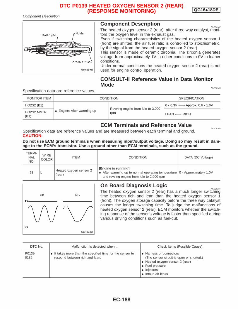
Component DescriptionNLEC0162
The heated oxygen sensor 2 (rear), after three way catalyst, moni-tors the oxygen level in the exhaust gas.Even if switching characteristics of the heated oxygen sensor 1(front) are shifted, the air fuel ratio is controlled to stoichiometric,by the signal from the heated oxygen sensor 2 (rear).This sensor is made of ceramic zirconia. The zirconia generatesvoltage from approximately 1V in richer conditions to 0V in leanerconditions.Under normal conditions the heated oxygen sensor 2 (rear) is notused for engine control operation.
CONSULT-II Reference Value in Data MonitorMode
NLEC0163
Specification data are reference values.
MONITOR ITEM CONDITION SPECIFICATION
HO2S2 (B1)
I Engine: After warming upRevving engine from idle to 3,000rpm
0 - 0.3V +, Approx. 0.6 - 1.0V
HO2S2 MNTR(B1)
LEAN +, RICH
ECM Terminals and Reference ValueNLEC0164
Specification data are reference values and are measured between each terminal and ground.CAUTION:Do not use ECM ground terminals when measuring input/output voltage. Doing so may result in dam-age to the ECM’s transistor. Use a ground other than ECM terminals, such as the ground.
TERMI-NALNO.
WIRECOLOR
ITEM CONDITION DATA (DC Voltage)
63 LHeated oxygen sensor 2(rear)
[Engine is running]I After warming up to normal operating temperature
and revving engine from idle to 2,000 rpm0 - Approximately 1.0V
On Board Diagnosis LogicNLEC0165
The heated oxygen sensor 2 (rear) has a much longer switchingtime between rich and lean than the heated oxygen sensor 1(front). The oxygen storage capacity before the three way catalystcauses the longer switching time. To judge the malfunctions ofheated oxygen sensor 2 (rear), ECM monitors whether the switch-ing response of the sensor’s voltage is faster than specified duringvarious driving conditions such as fuel-cut.
DTC No. Malfunction is detected when ... Check Items (Possible Cause)
P01390139
I It takes more than the specified time for the sensor torespond between rich and lean.
I Harness or connectors(The sensor circuit is open or shorted.)
I Heated oxygen sensor 2 (rear)I Fuel pressureI InjectorsI Intake air leaks
SEF327R
SEF302U
DTC P0139 HEATED OXYGEN SENSOR 2 (REAR)(RESPONSE MONITORING) QG16I18DE
Component Description
EC-188
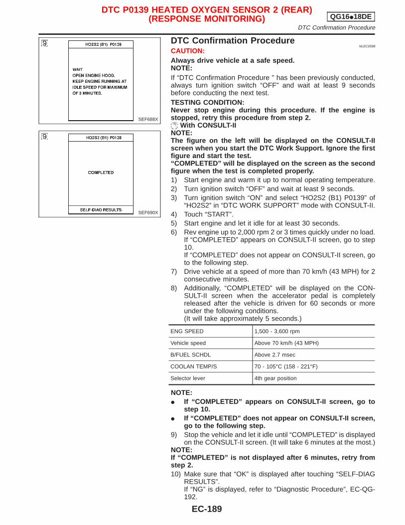
DTC Confirmation ProcedureNLEC0598
CAUTION:Always drive vehicle at a safe speed.NOTE:If “DTC Confirmation Procedure ” has been previously conducted,always turn ignition switch “OFF” and wait at least 9 secondsbefore conducting the next test.TESTING CONDITION:Never stop engine during this procedure. If the engine isstopped, retry this procedure from step 2.
With CONSULT-IINOTE:The figure on the left will be displayed on the CONSULT-IIscreen when you start the DTC Work Support. Ignore the firstfigure and start the test.“COMPLETED” will be displayed on the screen as the secondfigure when the test is completed properly.1) Start engine and warm it up to normal operating temperature.2) Turn ignition switch “OFF” and wait at least 9 seconds.3) Turn ignition switch “ON” and select “HO2S2 (B1) P0139” of
“HO2S2” in “DTC WORK SUPPORT” mode with CONSULT-II.4) Touch “START”.5) Start engine and let it idle for at least 30 seconds.6) Rev engine up to 2,000 rpm 2 or 3 times quickly under no load.
If “COMPLETED” appears on CONSULT-II screen, go to step10.If “COMPLETED” does not appear on CONSULT-II screen, goto the following step.
7) Drive vehicle at a speed of more than 70 km/h (43 MPH) for 2consecutive minutes.
8) Additionally, “COMPLETED” will be displayed on the CON-SULT-II screen when the accelerator pedal is completelyreleased after the vehicle is driven for 60 seconds or moreunder the following conditions.(It will take approximately 5 seconds.)
ENG SPEED 1,500 - 3,600 rpm
Vehicle speed Above 70 km/h (43 MPH)
B/FUEL SCHDL Above 2.7 msec
COOLAN TEMP/S 70 - 105°C (158 - 221°F)
Selector lever 4th gear position
NOTE:I If “COMPLETED” appears on CONSULT-II screen, go to
step 10.I If “COMPLETED” does not appear on CONSULT-II screen,
go to the following step.9) Stop the vehicle and let it idle until “COMPLETED” is displayed
on the CONSULT-II screen. (It will take 6 minutes at the most.)NOTE:If “COMPLETED” is not displayed after 6 minutes, retry fromstep 2.10) Make sure that “OK” is displayed after touching “SELF-DIAG
RESULTS”.If “NG” is displayed, refer to “Diagnostic Procedure”, EC-QG-192.
SEF688X
SEF690X
DTC P0139 HEATED OXYGEN SENSOR 2 (REAR)(RESPONSE MONITORING) QG16I18DE
DTC Confirmation Procedure
EC-189
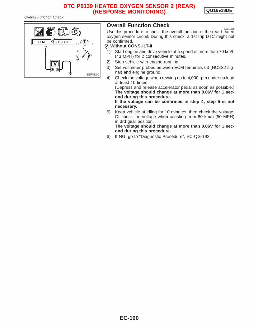
Overall Function CheckNLEC0599
Use this procedure to check the overall function of the rear heatedoxygen sensor circuit. During this check, a 1st trip DTC might notbe confirmed.
Without CONSULT-II1) Start engine and drive vehicle at a speed of more than 70 km/h
(43 MPH) for 2 consecutive minutes.2) Stop vehicle with engine running.3) Set voltmeter probes between ECM terminals 63 (HO2S2 sig-
nal) and engine ground.4) Check the voltage when revving up to 4,000 rpm under no load
at least 10 times.(Depress and release accelerator pedal as soon as possible.)The voltage should change at more than 0.06V for 1 sec-ond during this procedure.If the voltage can be confirmed in step 4, step 5 is notnecessary.
5) Keep vehicle at idling for 10 minutes, then check the voltage.Or check the voltage when coasting from 80 km/h (50 MPH)in 3rd gear position.The voltage should change at more than 0.06V for 1 sec-ond during this procedure.
6) If NG, go to “Diagnostic Procedure”, EC-QG-192.
SEF032X
DTC P0139 HEATED OXYGEN SENSOR 2 (REAR)(RESPONSE MONITORING) QG16I18DE
Overall Function Check
EC-190
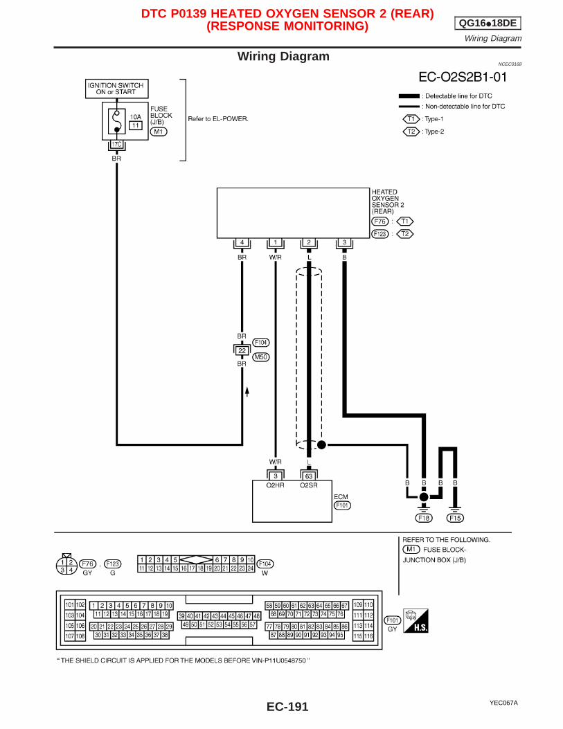
Wiring DiagramNCEC0168
YEC067A
DTC P0139 HEATED OXYGEN SENSOR 2 (REAR)(RESPONSE MONITORING) QG16I18DE
Wiring Diagram
EC-191
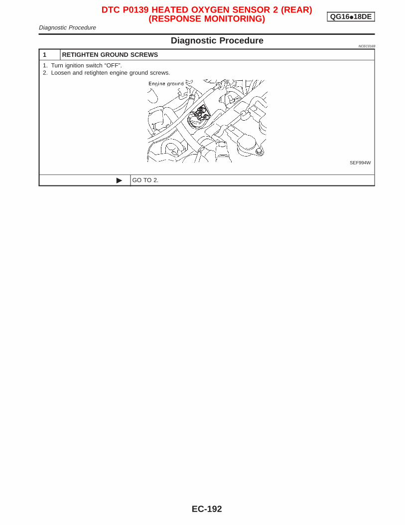
Diagnostic ProcedureNCEC0169
1 RETIGHTEN GROUND SCREWS
1. Turn ignition switch “OFF”.2. Loosen and retighten engine ground screws.
SEF994W
© GO TO 2.
DTC P0139 HEATED OXYGEN SENSOR 2 (REAR)(RESPONSE MONITORING) QG16I18DE
Diagnostic Procedure
EC-192
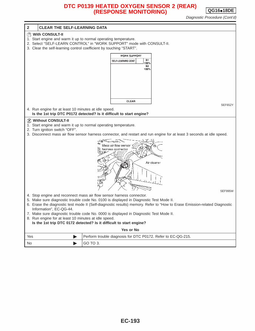
2 CLEAR THE SELF-LEARNING DATA
With CONSULT-II1. Start engine and warm it up to normal operating temperature.2. Select “SELF-LEARN CONTROL” in “WORK SUPPORT” mode with CONSULT-II.3. Clear the self-learning control coefficient by touching “START”.
SEF652Y
4. Run engine for at least 10 minutes at idle speed.Is the 1st trip DTC P0172 detected? Is it difficult to start engine?
Without CONSULT-II1. Start engine and warm it up to normal operating temperature.2. Turn ignition switch “OFF”.3. Disconnect mass air flow sensor harness connector, and restart and run engine for at least 3 seconds at idle speed.
SEF995W
4. Stop engine and reconnect mass air flow sensor harness connector.5. Make sure diagnostic trouble code No. 0100 is displayed in Diagnostic Test Mode II.6. Erase the diagnostic test mode II (Self-diagnostic results) memory. Refer to “How to Erase Emission-related Diagnostic
Information”, EC-QG-44.7. Make sure diagnostic trouble code No. 0000 is displayed in Diagnostic Test Mode II.8. Run engine for at least 10 minutes at idle speed.
Is the 1st trip DTC 0172 detected? Is it difficult to start engine?
Yes or No
Yes © Perform trouble diagnosis for DTC P0172. Refer to EC-QG-215.
No © GO TO 3.
DTC P0139 HEATED OXYGEN SENSOR 2 (REAR)(RESPONSE MONITORING) QG16I18DE
Diagnostic Procedure (Cont’d)
EC-193
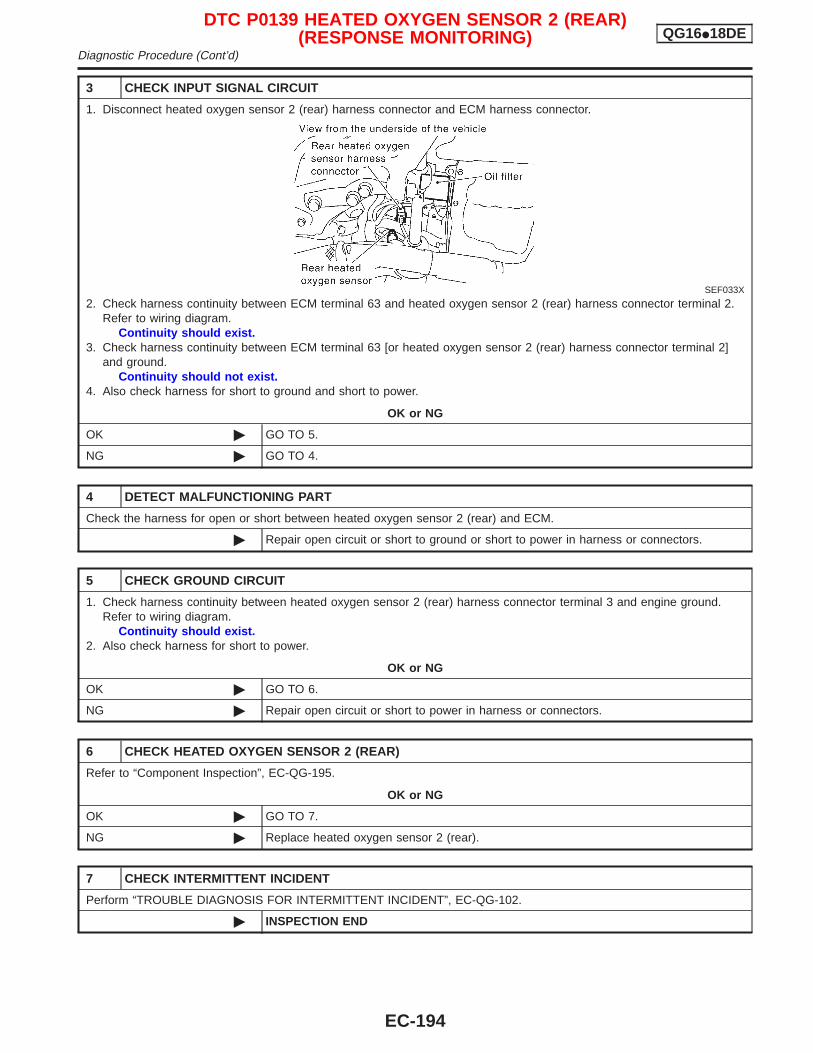
3 CHECK INPUT SIGNAL CIRCUIT
1. Disconnect heated oxygen sensor 2 (rear) harness connector and ECM harness connector.
SEF033X
2. Check harness continuity between ECM terminal 63 and heated oxygen sensor 2 (rear) harness connector terminal 2.Refer to wiring diagram.
Continuity should exist.3. Check harness continuity between ECM terminal 63 [or heated oxygen sensor 2 (rear) harness connector terminal 2]
and ground.Continuity should not exist.
4. Also check harness for short to ground and short to power.
OK or NG
OK © GO TO 5.
NG © GO TO 4.
4 DETECT MALFUNCTIONING PART
Check the harness for open or short between heated oxygen sensor 2 (rear) and ECM.
© Repair open circuit or short to ground or short to power in harness or connectors.
5 CHECK GROUND CIRCUIT
1. Check harness continuity between heated oxygen sensor 2 (rear) harness connector terminal 3 and engine ground.Refer to wiring diagram.
Continuity should exist.2. Also check harness for short to power.
OK or NG
OK © GO TO 6.
NG © Repair open circuit or short to power in harness or connectors.
6 CHECK HEATED OXYGEN SENSOR 2 (REAR)
Refer to “Component Inspection”, EC-QG-195.
OK or NG
OK © GO TO 7.
NG © Replace heated oxygen sensor 2 (rear).
7 CHECK INTERMITTENT INCIDENT
Perform “TROUBLE DIAGNOSIS FOR INTERMITTENT INCIDENT”, EC-QG-102.
© INSPECTION END
DTC P0139 HEATED OXYGEN SENSOR 2 (REAR)(RESPONSE MONITORING) QG16I18DE
Diagnostic Procedure (Cont’d)
EC-194
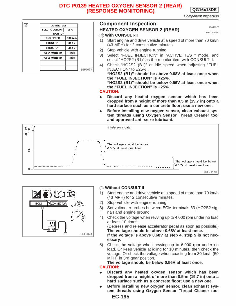
Component InspectionNLEC0170
HEATED OXYGEN SENSOR 2 (REAR)NLEC0170S01
With CONSULT-II1) Start engine and drive vehicle at a speed of more than 70 km/h
(43 MPH) for 2 consecutive minutes.2) Stop vehicle with engine running.3) Select “FUEL INJECTION” in “ACTIVE TEST” mode, and
select “HO2S2 (B1)” as the monitor item with CONSULT-II.4) Check “HO2S2 (B1)” at idle speed when adjusting “FUEL
INJECTION” to ±25%.“HO2S2 (B1)” should be above 0.68V at least once whenthe “FUEL INJECTION” is +25%.“HO2S2 (B1)” should be below 0.56V at least once whenthe “FUEL INJECTION” is −25%.
CAUTION:I Discard any heated oxygen sensor which has been
dropped from a height of more than 0.5 m (19.7 in) onto ahard surface such as a concrete floor; use a new one.
I Before installing new oxygen sensor, clean exhaust sys-tem threads using Oxygen Sensor Thread Cleaner tooland approved anti-seize lubricant.
Without CONSULT-II1) Start engine and drive vehicle at a speed of more than 70 km/h
(43 MPH) for 2 consecutive minutes.2) Stop vehicle with engine running.3) Set voltmeter probes between ECM terminals 63 (HO2S2 sig-
nal) and engine ground.4) Check the voltage when revving up to 4,000 rpm under no load
at least 10 times.(Depress and release accelerator pedal as soon as possible.)The voltage should be above 0.68V at least once.If the voltage is above 0.68V at step 4, step 5 is not nec-essary.
5) Check the voltage when revving up to 6,000 rpm under noload. Or keep vehicle at idling for 10 minutes, then check thevoltage. Or check the voltage when coasting from 80 km/h (50MPH) in 3rd gear position.The voltage should be below 0.56V at least once.
CAUTION:I Discard any heated oxygen sensor which has been
dropped from a height of more than 0.5 m (19.7 in) onto ahard surface such as a concrete floor; use a new one.
I Before installing new oxygen sensor, clean exhaust sys-tem threads using Oxygen Sensor Thread Cleaner tool
SEF662Y
SEF244YA
SEF032X
DTC P0139 HEATED OXYGEN SENSOR 2 (REAR)(RESPONSE MONITORING) QG16I18DE
Component Inspection
EC-195

and approved anti-seize lubricant.
DTC P0139 HEATED OXYGEN SENSOR 2 (REAR)(RESPONSE MONITORING) QG16I18DE
Component Inspection (Cont’d)
EC-196
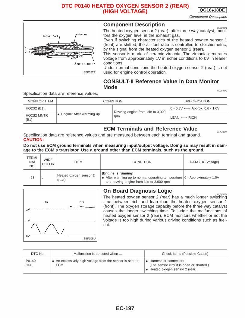
Component DescriptionNLEC0171
The heated oxygen sensor 2 (rear), after three way catalyst, moni-tors the oxygen level in the exhaust gas.Even if switching characteristics of the heated oxygen sensor 1(front) are shifted, the air fuel ratio is controlled to stoichiometric,by the signal from the heated oxygen sensor 2 (rear).This sensor is made of ceramic zirconia. The zirconia generatesvoltage from approximately 1V in richer conditions to 0V in leanerconditions.Under normal conditions the heated oxygen sensor 2 (rear) is notused for engine control operation.
CONSULT-II Reference Value in Data MonitorMode
NLEC0172
Specification data are reference values.
MONITOR ITEM CONDITION SPECIFICATION
HO2S2 (B1)
I Engine: After warming upRevving engine from idle to 3,000rpm
0 - 0.3V +, Approx. 0.6 - 1.0V
HO2S2 MNTR(B1)
LEAN +, RICH
ECM Terminals and Reference ValueNLEC0173
Specification data are reference values and are measured between each terminal and ground.CAUTION:Do not use ECM ground terminals when measuring input/output voltage. Doing so may result in dam-age to the ECM’s transistor. Use a ground other than ECM terminals, such as the ground.
TERMI-NALNO.
WIRECOLOR
ITEM CONDITION DATA (DC Voltage)
63 LHeated oxygen sensor 2(rear)
[Engine is running]I After warming up to normal operating temperature
and revving engine from idle to 2,000 rpm0 - Approximately 1.0V
On Board Diagnosis LogicNLEC0174
The heated oxygen sensor 2 (rear) has a much longer switchingtime between rich and lean than the heated oxygen sensor 1(front). The oxygen storage capacity before the three way catalystcauses the longer switching time. To judge the malfunctions ofheated oxygen sensor 2 (rear), ECM monitors whether or not thevoltage is too high during various driving conditions such as fuel-cut.
DTC No. Malfunction is detected when ... Check Items (Possible Cause)
P01400140
I An excessively high voltage from the sensor is sent toECM.
I Harness or connectors(The sensor circuit is open or shorted.)
I Heated oxygen sensor 2 (rear)
SEF327R
SEF305U
DTC P0140 HEATED OXYGEN SENSOR 2 (REAR)(HIGH VOLTAGE) QG16I18DE
Component Description
EC-197
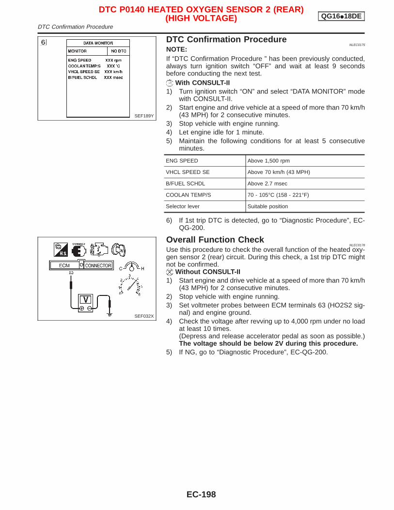
DTC Confirmation ProcedureNLEC0175
NOTE:If “DTC Confirmation Procedure ” has been previously conducted,always turn ignition switch “OFF” and wait at least 9 secondsbefore conducting the next test.
With CONSULT-II1) Turn ignition switch “ON” and select “DATA MONITOR” mode
with CONSULT-II.2) Start engine and drive vehicle at a speed of more than 70 km/h
(43 MPH) for 2 consecutive minutes.3) Stop vehicle with engine running.4) Let engine idle for 1 minute.5) Maintain the following conditions for at least 5 consecutive
minutes.
ENG SPEED Above 1,500 rpm
VHCL SPEED SE Above 70 km/h (43 MPH)
B/FUEL SCHDL Above 2.7 msec
COOLAN TEMP/S 70 - 105°C (158 - 221°F)
Selector lever Suitable position
6) If 1st trip DTC is detected, go to “Diagnostic Procedure”, EC-QG-200.
Overall Function CheckNLEC0176
Use this procedure to check the overall function of the heated oxy-gen sensor 2 (rear) circuit. During this check, a 1st trip DTC mightnot be confirmed.
Without CONSULT-II1) Start engine and drive vehicle at a speed of more than 70 km/h
(43 MPH) for 2 consecutive minutes.2) Stop vehicle with engine running.3) Set voltmeter probes between ECM terminals 63 (HO2S2 sig-
nal) and engine ground.4) Check the voltage after revving up to 4,000 rpm under no load
at least 10 times.(Depress and release accelerator pedal as soon as possible.)The voltage should be below 2V during this procedure.
5) If NG, go to “Diagnostic Procedure”, EC-QG-200.
SEF189Y
SEF032X
DTC P0140 HEATED OXYGEN SENSOR 2 (REAR)(HIGH VOLTAGE) QG16I18DE
DTC Confirmation Procedure
EC-198
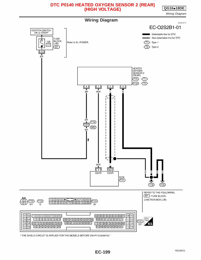
Wiring DiagramNCEC0177
YEC067A
DTC P0140 HEATED OXYGEN SENSOR 2 (REAR)(HIGH VOLTAGE) QG16I18DE
Wiring Diagram
EC-199
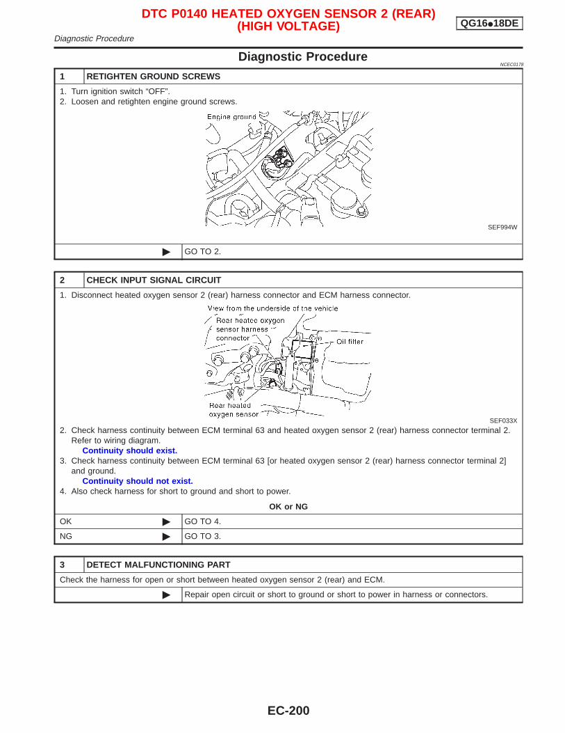
Diagnostic ProcedureNCEC0178
1 RETIGHTEN GROUND SCREWS
1. Turn ignition switch “OFF”.2. Loosen and retighten engine ground screws.
SEF994W
© GO TO 2.
2 CHECK INPUT SIGNAL CIRCUIT
1. Disconnect heated oxygen sensor 2 (rear) harness connector and ECM harness connector.
SEF033X
2. Check harness continuity between ECM terminal 63 and heated oxygen sensor 2 (rear) harness connector terminal 2.Refer to wiring diagram.
Continuity should exist.3. Check harness continuity between ECM terminal 63 [or heated oxygen sensor 2 (rear) harness connector terminal 2]
and ground.Continuity should not exist.
4. Also check harness for short to ground and short to power.
OK or NG
OK © GO TO 4.
NG © GO TO 3.
3 DETECT MALFUNCTIONING PART
Check the harness for open or short between heated oxygen sensor 2 (rear) and ECM.
© Repair open circuit or short to ground or short to power in harness or connectors.
DTC P0140 HEATED OXYGEN SENSOR 2 (REAR)(HIGH VOLTAGE) QG16I18DE
Diagnostic Procedure
EC-200
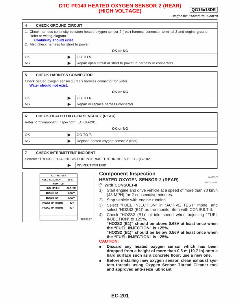
4 CHECK GROUND CIRCUIT
1. Check harness continuity between heated oxygen sensor 2 (rear) harness connector terminal 3 and engine ground.Refer to wiring diagram.
Continuity should exist.2. Also check harness for short to power.
OK or NG
OK © GO TO 5.
NG © Repair open circuit or short to power in harness or connectors.
5 CHECK HARNESS CONNECTOR
Check heated oxygen sensor 2 (rear) harness connector for water.Water should not exist.
OK or NG
OK © GO TO 6.
NG © Repair or replace harness connector.
6 CHECK HEATED OXYGEN SENSOR 2 (REAR)
Refer to “Component Inspection”, EC-QG-201.
OK or NG
OK © GO TO 7.
NG © Replace heated oxygen sensor 2 (rear).
7 CHECK INTERMITTENT INCIDENT
Perform “TROUBLE DIAGNOSIS FOR INTERMITTENT INCIDENT”, EC-QG-102.
© INSPECTION END
Component InspectionNLEC0179
HEATED OXYGEN SENSOR 2 (REAR)NLEC0179S01
With CONSULT-II1) Start engine and drive vehicle at a speed of more than 70 km/h
(43 MPH) for 2 consecutive minutes.2) Stop vehicle with engine running.3) Select “FUEL INJECTION” in “ACTIVE TEST” mode, and
select “HO2S2 (B1)” as the monitor item with CONSULT-II.4) Check “HO2S2 (B1)” at idle speed when adjusting “FUEL
INJECTION” to ±25%.“HO2S2 (B1)” should be above 0.68V at least once whenthe “FUEL INJECTION” is +25%.“HO2S2 (B1)” should be below 0.56V at least once whenthe “FUEL INJECTION” is −25%.
CAUTION:I Discard any heated oxygen sensor which has been
dropped from a height of more than 0.5 m (19.7 in) onto ahard surface such as a concrete floor; use a new one.
I Before installing new oxygen sensor, clean exhaust sys-tem threads using Oxygen Sensor Thread Cleaner tooland approved anti-seize lubricant.
SEF662Y
DTC P0140 HEATED OXYGEN SENSOR 2 (REAR)(HIGH VOLTAGE) QG16I18DE
Diagnostic Procedure (Cont’d)
EC-201
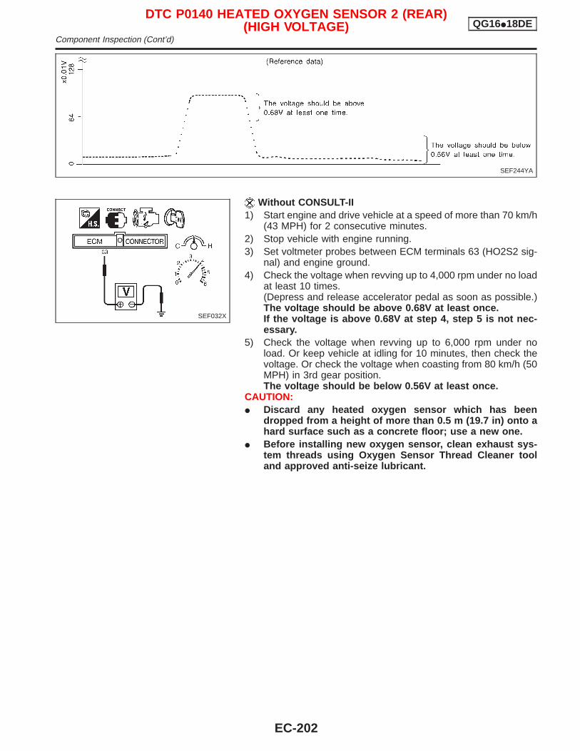
Without CONSULT-II1) Start engine and drive vehicle at a speed of more than 70 km/h
(43 MPH) for 2 consecutive minutes.2) Stop vehicle with engine running.3) Set voltmeter probes between ECM terminals 63 (HO2S2 sig-
nal) and engine ground.4) Check the voltage when revving up to 4,000 rpm under no load
at least 10 times.(Depress and release accelerator pedal as soon as possible.)The voltage should be above 0.68V at least once.If the voltage is above 0.68V at step 4, step 5 is not nec-essary.
5) Check the voltage when revving up to 6,000 rpm under noload. Or keep vehicle at idling for 10 minutes, then check thevoltage. Or check the voltage when coasting from 80 km/h (50MPH) in 3rd gear position.The voltage should be below 0.56V at least once.
CAUTION:I Discard any heated oxygen sensor which has been
dropped from a height of more than 0.5 m (19.7 in) onto ahard surface such as a concrete floor; use a new one.
I Before installing new oxygen sensor, clean exhaust sys-tem threads using Oxygen Sensor Thread Cleaner tooland approved anti-seize lubricant.
SEF244YA
SEF032X
DTC P0140 HEATED OXYGEN SENSOR 2 (REAR)(HIGH VOLTAGE) QG16I18DE
Component Inspection (Cont’d)
EC-202
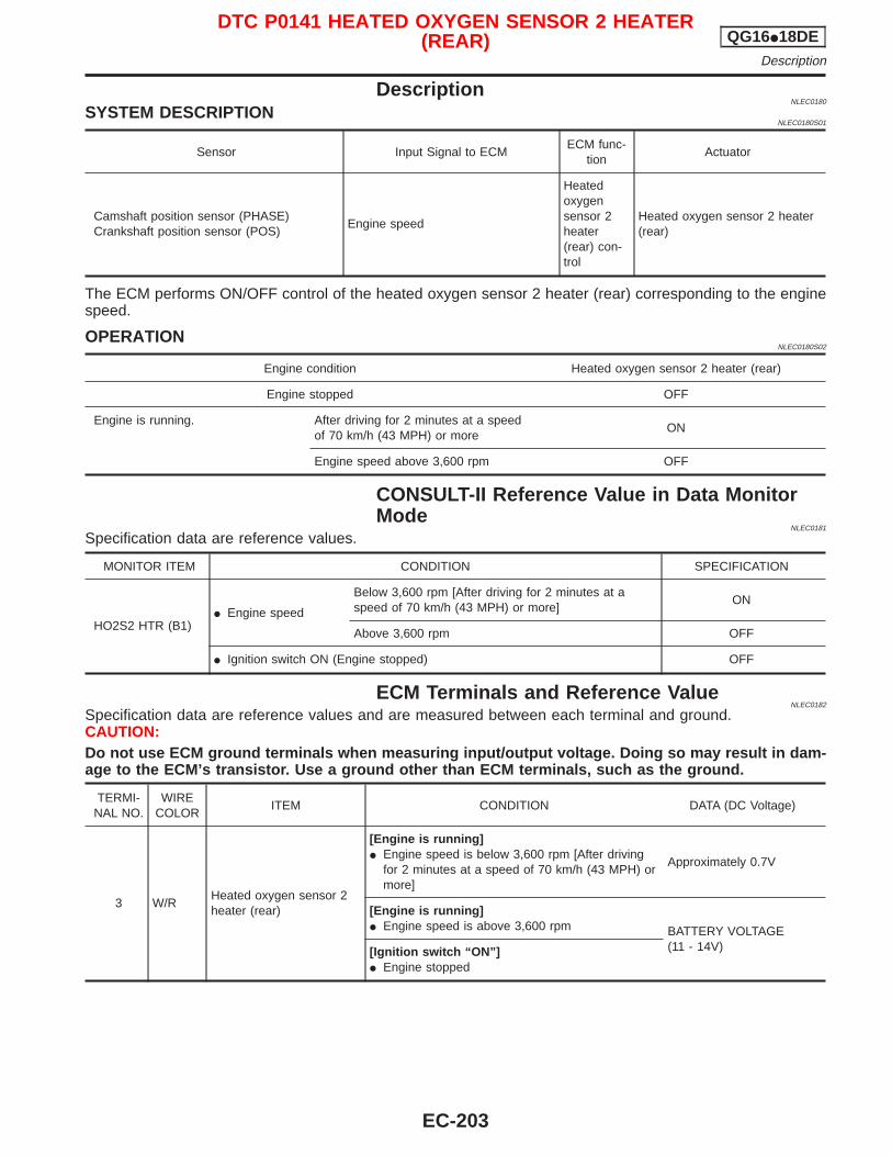
DescriptionNLEC0180
SYSTEM DESCRIPTIONNLEC0180S01
Sensor Input Signal to ECMECM func-
tionActuator
Camshaft position sensor (PHASE)Crankshaft position sensor (POS)
Engine speed
Heatedoxygensensor 2heater(rear) con-trol
Heated oxygen sensor 2 heater(rear)
The ECM performs ON/OFF control of the heated oxygen sensor 2 heater (rear) corresponding to the enginespeed.
OPERATIONNLEC0180S02
Engine condition Heated oxygen sensor 2 heater (rear)
Engine stopped OFF
Engine is running. After driving for 2 minutes at a speedof 70 km/h (43 MPH) or more
ON
Engine speed above 3,600 rpm OFF
CONSULT-II Reference Value in Data MonitorMode
NLEC0181
Specification data are reference values.
MONITOR ITEM CONDITION SPECIFICATION
HO2S2 HTR (B1)I Engine speed
Below 3,600 rpm [After driving for 2 minutes at aspeed of 70 km/h (43 MPH) or more]
ON
Above 3,600 rpm OFF
I Ignition switch ON (Engine stopped) OFF
ECM Terminals and Reference ValueNLEC0182
Specification data are reference values and are measured between each terminal and ground.CAUTION:Do not use ECM ground terminals when measuring input/output voltage. Doing so may result in dam-age to the ECM’s transistor. Use a ground other than ECM terminals, such as the ground.
TERMI-NAL NO.
WIRECOLOR
ITEM CONDITION DATA (DC Voltage)
3 W/RHeated oxygen sensor 2heater (rear)
[Engine is running]I Engine speed is below 3,600 rpm [After driving
for 2 minutes at a speed of 70 km/h (43 MPH) ormore]
Approximately 0.7V
[Engine is running]I Engine speed is above 3,600 rpm BATTERY VOLTAGE
(11 - 14V)[Ignition switch “ON”]I Engine stopped
DTC P0141 HEATED OXYGEN SENSOR 2 HEATER(REAR) QG16I18DE
Description
EC-203
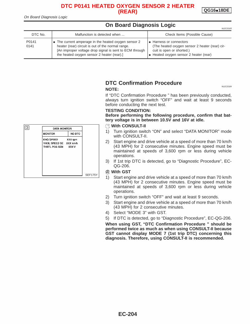
On Board Diagnosis LogicNLEC0183
DTC No. Malfunction is detected when ... Check Items (Possible Cause)
P01410141
I The current amperage in the heated oxygen sensor 2heater (rear) circuit is out of the normal range.[An improper voltage drop signal is sent to ECM throughthe heated oxygen sensor 2 heater (rear).]
I Harness or connectors(The heated oxygen sensor 2 heater (rear) cir-cuit is open or shorted.)
I Heated oxygen sensor 2 heater (rear)
DTC Confirmation ProcedureNLEC0184
NOTE:If “DTC Confirmation Procedure ” has been previously conducted,always turn ignition switch “OFF” and wait at least 9 secondsbefore conducting the next test.TESTING CONDITION:Before performing the following procedure, confirm that bat-tery voltage is in between 10.5V and 16V at idle.
With CONSULT-II1) Turn ignition switch “ON” and select “DATA MONITOR” mode
with CONSULT-II.2) Start engine and drive vehicle at a speed of more than 70 km/h
(43 MPH) for 2 consecutive minutes. Engine speed must bemaintained at speeds of 3,600 rpm or less during vehicleoperations.
3) If 1st trip DTC is detected, go to “Diagnostic Procedure”, EC-QG-206.
With GST1) Start engine and drive vehicle at a speed of more than 70 km/h
(43 MPH) for 2 consecutive minutes. Engine speed must bemaintained at speeds of 3,600 rpm or less during vehicleoperations.
2) Turn ignition switch “OFF” and wait at least 9 seconds.3) Start engine and drive vehicle at a speed of more than 70 km/h
(43 MPH) for 2 consecutive minutes.4) Select “MODE 3” with GST.5) If DTC is detected, go to “Diagnostic Procedure”, EC-QG-206.When using GST, “DTC Confirmation Procedure ” should beperformed twice as much as when using CONSULT-II becauseGST cannot display MODE 7 (1st trip DTC) concerning thisdiagnosis. Therefore, using CONSULT-II is recommended.
SEF175Y
DTC P0141 HEATED OXYGEN SENSOR 2 HEATER(REAR) QG16I18DE
On Board Diagnosis Logic
EC-204

Wiring DiagramNCEC0185
YEC068A
DTC P0141 HEATED OXYGEN SENSOR 2 HEATER(REAR) QG16I18DE
Wiring Diagram
EC-205
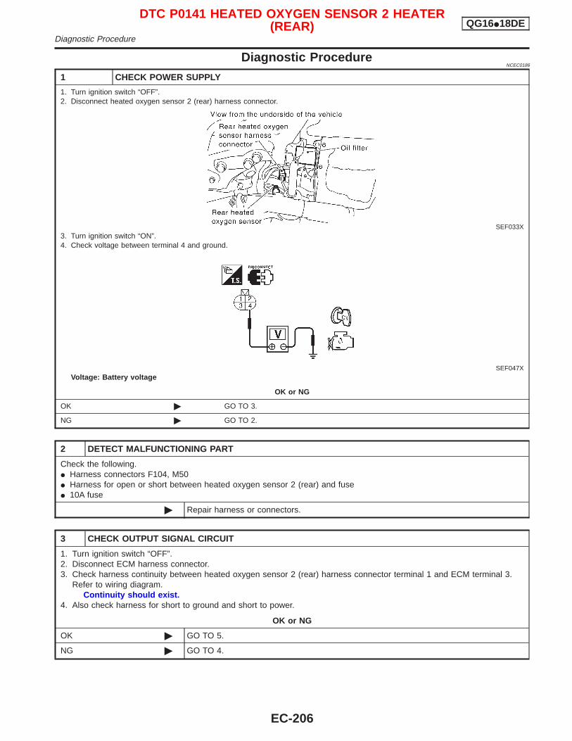
Diagnostic ProcedureNCEC0186
1 CHECK POWER SUPPLY
1. Turn ignition switch “OFF”.2. Disconnect heated oxygen sensor 2 (rear) harness connector.
SEF033X3. Turn ignition switch “ON”.4. Check voltage between terminal 4 and ground.
SEF047XVoltage: Battery voltage
OK or NG
OK © GO TO 3.
NG © GO TO 2.
2 DETECT MALFUNCTIONING PART
Check the following.I Harness connectors F104, M50I Harness for open or short between heated oxygen sensor 2 (rear) and fuseI 10A fuse
© Repair harness or connectors.
3 CHECK OUTPUT SIGNAL CIRCUIT
1. Turn ignition switch “OFF”.2. Disconnect ECM harness connector.3. Check harness continuity between heated oxygen sensor 2 (rear) harness connector terminal 1 and ECM terminal 3.
Refer to wiring diagram.Continuity should exist.
4. Also check harness for short to ground and short to power.
OK or NG
OK © GO TO 5.
NG © GO TO 4.
DTC P0141 HEATED OXYGEN SENSOR 2 HEATER(REAR) QG16I18DE
Diagnostic Procedure
EC-206
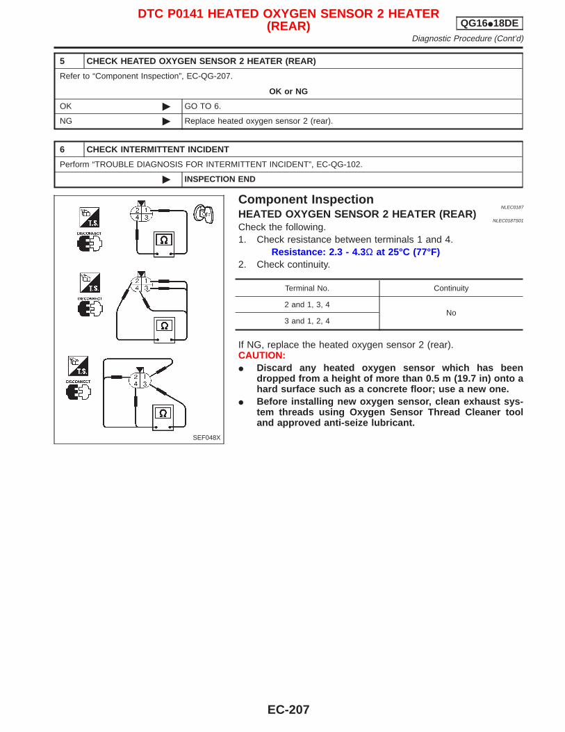
5 CHECK HEATED OXYGEN SENSOR 2 HEATER (REAR)
Refer to “Component Inspection”, EC-QG-207.
OK or NG
OK © GO TO 6.
NG © Replace heated oxygen sensor 2 (rear).
6 CHECK INTERMITTENT INCIDENT
Perform “TROUBLE DIAGNOSIS FOR INTERMITTENT INCIDENT”, EC-QG-102.
© INSPECTION END
Component InspectionNLEC0187
HEATED OXYGEN SENSOR 2 HEATER (REAR)NLEC0187S01
Check the following.1. Check resistance between terminals 1 and 4.
Resistance: 2.3 - 4.3 Ω at 25°C (77°F)2. Check continuity.
Terminal No. Continuity
2 and 1, 3, 4No
3 and 1, 2, 4
If NG, replace the heated oxygen sensor 2 (rear).CAUTION:I Discard any heated oxygen sensor which has been
dropped from a height of more than 0.5 m (19.7 in) onto ahard surface such as a concrete floor; use a new one.
I Before installing new oxygen sensor, clean exhaust sys-tem threads using Oxygen Sensor Thread Cleaner tooland approved anti-seize lubricant.
SEF048X
DTC P0141 HEATED OXYGEN SENSOR 2 HEATER(REAR) QG16I18DE
Diagnostic Procedure (Cont’d)
EC-207
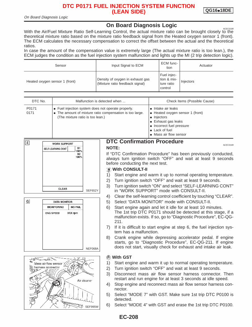
On Board Diagnosis LogicNCEC0188
With the Air/Fuel Mixture Ratio Self-Learning Control, the actual mixture ratio can be brought closely to thetheoretical mixture ratio based on the mixture ratio feedback signal from the Heated oxygen sensor 1 (front).The ECM calculates the necessary compensation to correct the offset between the actual and the theoreticalratios.In case the amount of the compensation value is extremely large (The actual mixture ratio is too lean.), theECM judges the condition as the fuel injection system malfunction and lights up the MI (2 trip detection logic).
Sensor Input Signal to ECMECM func-
tionActuator
Heated oxygen sensor 1 (front)Density of oxygen in exhaust gas(Mixture ratio feedback signal)
Fuel injec-tion & mix-ture ratiocontrol
Injectors
DTC No. Malfunction is detected when ... Check Items (Possible Cause)
P01710171
I Fuel injection system does not operate properly.I The amount of mixture ratio compensation is too large.
(The mixture ratio is too lean.)
I Intake air leaksI Heated oxygen sensor 1 (front)I InjectorsI Exhaust gas leaksI Incorrect fuel pressureI Lack of fuelI Mass air flow sensor
DTC Confirmation ProcedureNCEC0189
NOTE:If “DTC Confirmation Procedure” has been previously conducted,always turn ignition switch “OFF” and wait at least 9 secondsbefore conducting the next test.
With CONSULT-II1) Start engine and warm it up to normal operating temperature.2) Turn ignition switch “OFF” and wait at least 9 seconds.3) Turn ignition switch “ON” and select “SELF-LEARNING CONT”
in “WORK SUPPORT” mode with CONSULT-II.4) Clear the self-learning control coefficient by touching “CLEAR”.5) Select “DATA MONITOR” mode with CONSULT-II.6) Start engine again and let it idle for at least 10 minutes.
The 1st trip DTC P0171 should be detected at this stage, if amalfunction exists. If so, go to “Diagnostic Procedure”, EC-QG-211.
7) If it is difficult to start engine at step 6, the fuel injection sys-tem has a malfunction.
8) Crank engine while depressing accelerator pedal. If enginestarts, go to “Diagnostic Procedure”, EC-QG-211. If enginedoes not start, visually check for exhaust and intake air leak.
With GST1) Start engine and warm it up to normal operating temperature.2) Turn ignition switch “OFF” and wait at least 9 seconds.3) Disconnect mass air flow sensor harness connector. Then
restart and run engine for at least 3 seconds at idle speed.4) Stop engine and reconnect mass air flow sensor harness con-
nector.5) Select “MODE 7” with GST. Make sure 1st trip DTC P0100 is
detected.6) Select “MODE 4” with GST and erase the 1st trip DTC P0100.
SEF652Y
NEF068A
SEF995W
DTC P0171 FUEL INJECTION SYSTEM FUNCTION(LEAN SIDE) QG16I18DE
On Board Diagnosis Logic
EC-208
7) Start engine again and run it for at least 10 minutes at idlespeed.
8) Select “MODE 7” with GST. The 1st trip DTC P0171 should bedetected at this stage, if a malfunction exists. If so, go to“Diagnostic Procedure”, EC-QG-211.
9) If it is difficult to start engine at step 8, the fuel injection sys-tem has a malfunction.
10) Crank engine while depressing accelerator pedal. If enginestarts, go to “Diagnostic Procedure”, EC-QG-211. If enginedoes not start, visually check for exhaust and intake air leak.
DTC P0171 FUEL INJECTION SYSTEM FUNCTION(LEAN SIDE) QG16I18DE
DTC Confirmation Procedure (Cont’d)
EC-209
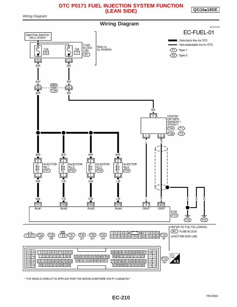
Wiring DiagramNCEC0190
YEC069A
DTC P0171 FUEL INJECTION SYSTEM FUNCTION(LEAN SIDE) QG16I18DE
Wiring Diagram
EC-210
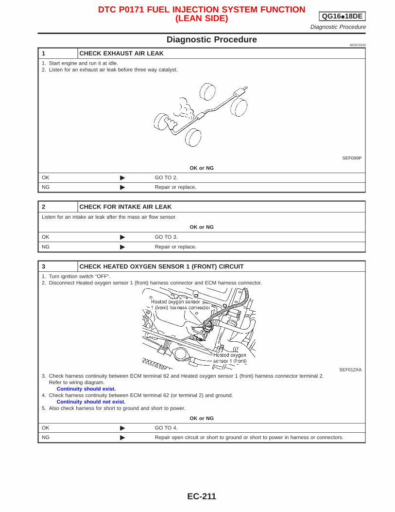
Diagnostic ProcedureNCEC0191
1 CHECK EXHAUST AIR LEAK
1. Start engine and run it at idle.2. Listen for an exhaust air leak before three way catalyst.
SEF099P
OK or NG
OK © GO TO 2.
NG © Repair or replace.
2 CHECK FOR INTAKE AIR LEAK
Listen for an intake air leak after the mass air flow sensor.
OK or NG
OK © GO TO 3.
NG © Repair or replace.
3 CHECK HEATED OXYGEN SENSOR 1 (FRONT) CIRCUIT
1. Turn ignition switch “OFF”.2. Disconnect Heated oxygen sensor 1 (front) harness connector and ECM harness connector.
SEF012XA3. Check harness continuity between ECM terminal 62 and Heated oxygen sensor 1 (front) harness connector terminal 2.
Refer to wiring diagram.Continuity should exist.
4. Check harness continuity between ECM terminal 62 (or terminal 2) and ground.Continuity should not exist.
5. Also check harness for short to ground and short to power.
OK or NG
OK © GO TO 4.
NG © Repair open circuit or short to ground or short to power in harness or connectors.
DTC P0171 FUEL INJECTION SYSTEM FUNCTION(LEAN SIDE) QG16I18DE
Diagnostic Procedure
EC-211
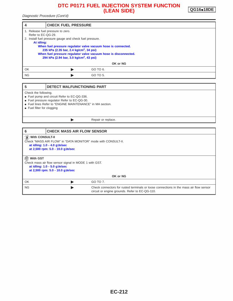
4 CHECK FUEL PRESSURE
1. Release fuel pressure to zero.Refer to EC-QG-29.
2. Install fuel pressure gauge and check fuel pressure.At idling:
When fuel pressure regulator valve vacuum hose is connected.235 kPa (2.35 bar, 2.4 kg/cm 2, 34 psi)
When fuel pressure regulator valve vacuum hose is disconnected.294 kPa (2.94 bar, 3.0 kg/cm 2, 43 psi)
OK or NG
OK © GO TO 6.
NG © GO TO 5.
5 DETECT MALFUNCTIONING PART
Check the following.I Fuel pump and circuit Refer to EC-QG-336.I Fuel pressure regulator Refer to EC-QG-30.I Fuel lines Refer to “ENGINE MAINTENANCE” in MA section.I Fuel filter for clogging
© Repair or replace.
6 CHECK MASS AIR FLOW SENSOR
With CONSULT-IICheck “MASS AIR FLOW” in “DATA MONITOR” mode with CONSULT-II.
at idling: 1.0 - 4.0 g ⋅m/secat 2,500 rpm: 5.0 - 10.0 g ⋅m/sec
With GSTCheck mass air flow sensor signal in MODE 1 with GST.
at idling: 1.0 - 5.0 g ⋅m/secat 2,500 rpm: 5.0 - 10.0 g ⋅m/sec
OK or NG
OK © GO TO 7.
NG © Check connectors for rusted terminals or loose connections in the mass air flow sensorcircuit or engine grounds. Refer to EC-QG-110.
DTC P0171 FUEL INJECTION SYSTEM FUNCTION(LEAN SIDE) QG16I18DE
Diagnostic Procedure (Cont’d)
EC-212
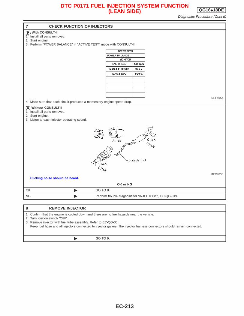
7 CHECK FUNCTION OF INJECTORS
With CONSULT-II1. Install all parts removed.2. Start engine.3. Perform “POWER BALANCE” in “ACTIVE TEST” mode with CONSULT-II.
NEF105A4. Make sure that each circuit produces a momentary engine speed drop.
Without CONSULT-II1. Install all parts removed.2. Start engine.3. Listen to each injector operating sound.
MEC703BClicking noise should be heard.
OK or NG
OK © GO TO 8.
NG © Perform trouble diagnosis for “INJECTORS”, EC-QG-319.
8 REMOVE INJECTOR
1. Confirm that the engine is cooled down and there are no fire hazards near the vehicle.2. Turn ignition switch “OFF”.3. Remove injector with fuel tube assembly. Refer to EC-QG-30.
Keep fuel hose and all injectors connected to injector gallery. The injector harness connectors should remain connected.
© GO TO 9.
DTC P0171 FUEL INJECTION SYSTEM FUNCTION(LEAN SIDE) QG16I18DE
Diagnostic Procedure (Cont’d)
EC-213
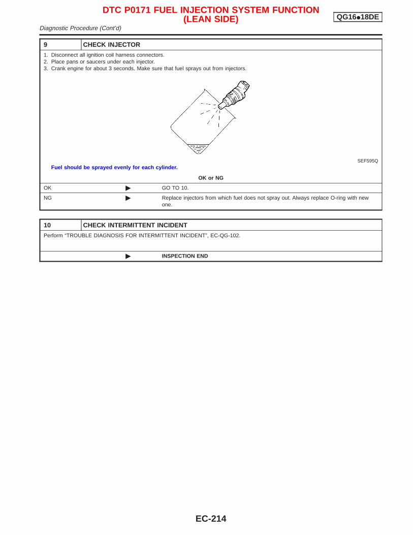
9 CHECK INJECTOR
1. Disconnect all ignition coil harness connectors.2. Place pans or saucers under each injector.3. Crank engine for about 3 seconds. Make sure that fuel sprays out from injectors.
SEF595QFuel should be sprayed evenly for each cylinder.
OK or NG
OK © GO TO 10.
NG © Replace injectors from which fuel does not spray out. Always replace O-ring with newone.
10 CHECK INTERMITTENT INCIDENT
Perform “TROUBLE DIAGNOSIS FOR INTERMITTENT INCIDENT”, EC-QG-102.
© INSPECTION END
DTC P0171 FUEL INJECTION SYSTEM FUNCTION(LEAN SIDE) QG16I18DE
Diagnostic Procedure (Cont’d)
EC-214
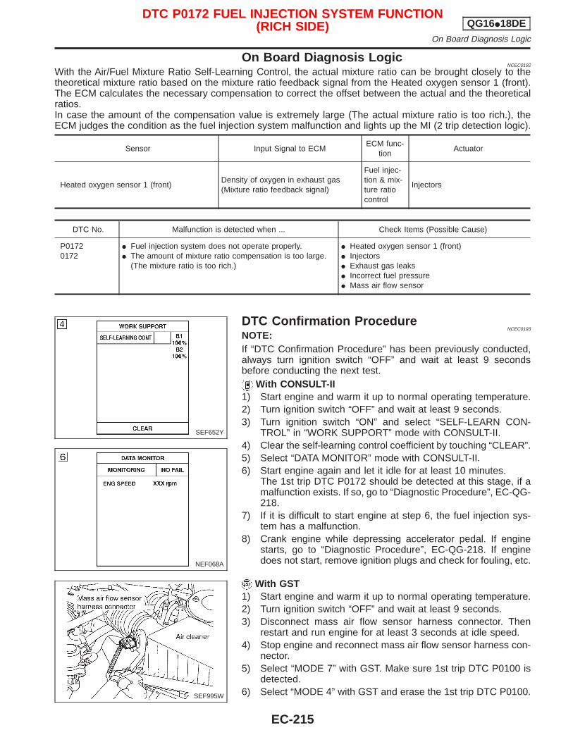
On Board Diagnosis LogicNCEC0192
With the Air/Fuel Mixture Ratio Self-Learning Control, the actual mixture ratio can be brought closely to thetheoretical mixture ratio based on the mixture ratio feedback signal from the Heated oxygen sensor 1 (front).The ECM calculates the necessary compensation to correct the offset between the actual and the theoreticalratios.In case the amount of the compensation value is extremely large (The actual mixture ratio is too rich.), theECM judges the condition as the fuel injection system malfunction and lights up the MI (2 trip detection logic).
Sensor Input Signal to ECMECM func-
tionActuator
Heated oxygen sensor 1 (front)Density of oxygen in exhaust gas(Mixture ratio feedback signal)
Fuel injec-tion & mix-ture ratiocontrol
Injectors
DTC No. Malfunction is detected when ... Check Items (Possible Cause)
P01720172
I Fuel injection system does not operate properly.I The amount of mixture ratio compensation is too large.
(The mixture ratio is too rich.)
I Heated oxygen sensor 1 (front)I InjectorsI Exhaust gas leaksI Incorrect fuel pressureI Mass air flow sensor
DTC Confirmation ProcedureNCEC0193
NOTE:If “DTC Confirmation Procedure” has been previously conducted,always turn ignition switch “OFF” and wait at least 9 secondsbefore conducting the next test.
With CONSULT-II1) Start engine and warm it up to normal operating temperature.2) Turn ignition switch “OFF” and wait at least 9 seconds.3) Turn ignition switch “ON” and select “SELF-LEARN CON-
TROL” in “WORK SUPPORT” mode with CONSULT-II.4) Clear the self-learning control coefficient by touching “CLEAR”.5) Select “DATA MONITOR” mode with CONSULT-II.6) Start engine again and let it idle for at least 10 minutes.
The 1st trip DTC P0172 should be detected at this stage, if amalfunction exists. If so, go to “Diagnostic Procedure”, EC-QG-218.
7) If it is difficult to start engine at step 6, the fuel injection sys-tem has a malfunction.
8) Crank engine while depressing accelerator pedal. If enginestarts, go to “Diagnostic Procedure”, EC-QG-218. If enginedoes not start, remove ignition plugs and check for fouling, etc.
With GST1) Start engine and warm it up to normal operating temperature.2) Turn ignition switch “OFF” and wait at least 9 seconds.3) Disconnect mass air flow sensor harness connector. Then
restart and run engine for at least 3 seconds at idle speed.4) Stop engine and reconnect mass air flow sensor harness con-
nector.5) Select “MODE 7” with GST. Make sure 1st trip DTC P0100 is
detected.6) Select “MODE 4” with GST and erase the 1st trip DTC P0100.
SEF652Y
NEF068A
SEF995W
DTC P0172 FUEL INJECTION SYSTEM FUNCTION(RICH SIDE) QG16I18DE
On Board Diagnosis Logic
EC-215
7) Start engine again and run it for at least 10 minutes at idlespeed.
8) Select “MODE 7” with GST. The 1st trip DTC P0172 should bedetected at this stage, if a malfunction exists. If so, go to“Diagnostic Procedure”, EC-QG-218.
9) If it is difficult to start engine at step 8, the fuel injection sys-tem has a malfunction.
10) Crank engine while depressing accelerator pedal.If engine starts, go to “Diagnostic Procedure”, EC-QG-218. Ifengine does not start, remove ignition plugs and check forfouling, etc.
DTC P0172 FUEL INJECTION SYSTEM FUNCTION(RICH SIDE) QG16I18DE
DTC Confirmation Procedure (Cont’d)
EC-216
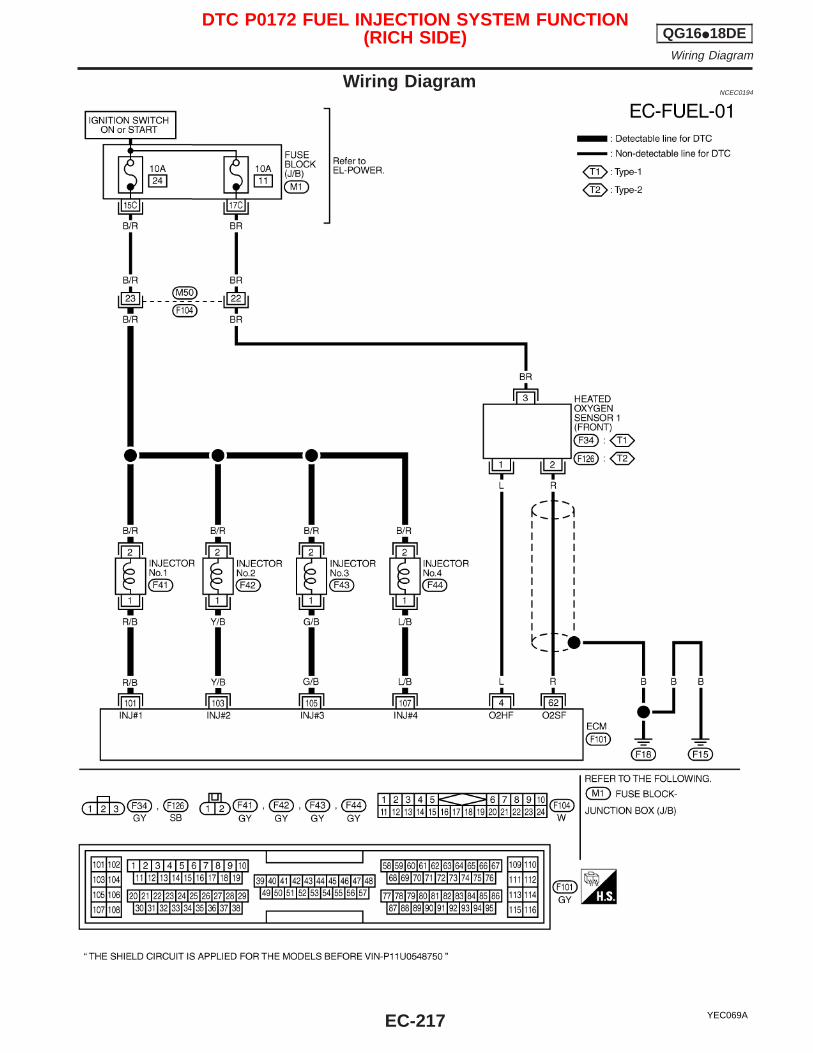
Wiring DiagramNCEC0194
YEC069A
DTC P0172 FUEL INJECTION SYSTEM FUNCTION(RICH SIDE) QG16I18DE
Wiring Diagram
EC-217
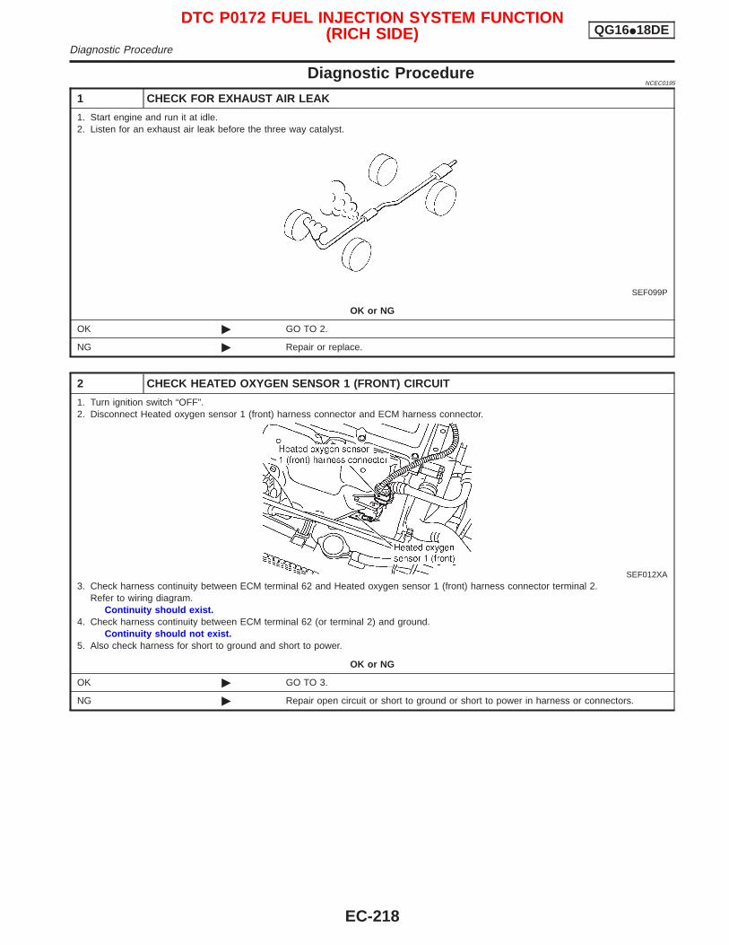
Diagnostic ProcedureNCEC0195
1 CHECK FOR EXHAUST AIR LEAK
1. Start engine and run it at idle.2. Listen for an exhaust air leak before the three way catalyst.
SEF099P
OK or NG
OK © GO TO 2.
NG © Repair or replace.
2 CHECK HEATED OXYGEN SENSOR 1 (FRONT) CIRCUIT
1. Turn ignition switch “OFF”.2. Disconnect Heated oxygen sensor 1 (front) harness connector and ECM harness connector.
SEF012XA3. Check harness continuity between ECM terminal 62 and Heated oxygen sensor 1 (front) harness connector terminal 2.
Refer to wiring diagram.Continuity should exist.
4. Check harness continuity between ECM terminal 62 (or terminal 2) and ground.Continuity should not exist.
5. Also check harness for short to ground and short to power.
OK or NG
OK © GO TO 3.
NG © Repair open circuit or short to ground or short to power in harness or connectors.
DTC P0172 FUEL INJECTION SYSTEM FUNCTION(RICH SIDE) QG16I18DE
Diagnostic Procedure
EC-218
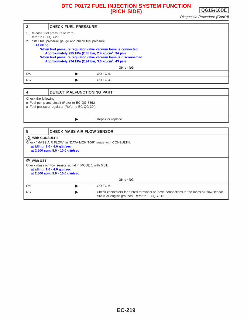
3 CHECK FUEL PRESSURE
1. Release fuel pressure to zero.Refer to EC-QG-29.
2. Install fuel pressure gauge and check fuel pressure.At idling:
When fuel pressure regulator valve vacuum hose is connected.Approximately 235 kPa (2.35 bar, 2.4 kg/cm 2, 34 psi)
When fuel pressure regulator valve vacuum hose is disconnected.Approximately 294 kPa (2.94 bar, 3.0 kg/cm 2, 43 psi)
OK or NG
OK © GO TO 5.
NG © GO TO 4.
4 DETECT MALFUNCTIONING PART
Check the following.I Fuel pump and circuit (Refer to EC-QG-336.)I Fuel pressure regulator (Refer to EC-QG-30.)
© Repair or replace.
5 CHECK MASS AIR FLOW SENSOR
With CONSULT-IICheck “MASS AIR FLOW” in “DATA MONITOR” mode with CONSULT-II.
at idling: 1.0 - 4.0 g ⋅m/secat 2,500 rpm: 5.0 - 10.0 g ⋅m/sec
With GSTCheck mass air flow sensor signal in MODE 1 with GST.
at idling: 1.0 - 4.0 g ⋅m/secat 2,500 rpm: 5.0 - 10.0 g ⋅m/sec
OK or NG
OK © GO TO 6.
NG © Check connectors for rusted terminals or loose connections in the mass air flow sensorcircuit or engine grounds. Refer to EC-QG-113.
DTC P0172 FUEL INJECTION SYSTEM FUNCTION(RICH SIDE) QG16I18DE
Diagnostic Procedure (Cont’d)
EC-219
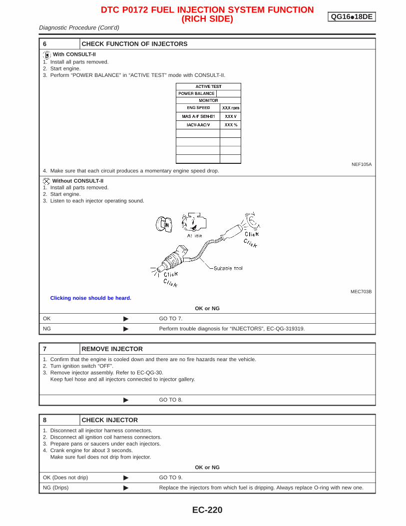
6 CHECK FUNCTION OF INJECTORS
With CONSULT-II1. Install all parts removed.2. Start engine.3. Perform “POWER BALANCE” in “ACTIVE TEST” mode with CONSULT-II.
NEF105A4. Make sure that each circuit produces a momentary engine speed drop.
Without CONSULT-II1. Install all parts removed.2. Start engine.3. Listen to each injector operating sound.
MEC703BClicking noise should be heard.
OK or NG
OK © GO TO 7.
NG © Perform trouble diagnosis for “INJECTORS”, EC-QG-319319.
7 REMOVE INJECTOR
1. Confirm that the engine is cooled down and there are no fire hazards near the vehicle.2. Turn ignition switch “OFF”.3. Remove injector assembly. Refer to EC-QG-30.
Keep fuel hose and all injectors connected to injector gallery.
© GO TO 8.
8 CHECK INJECTOR
1. Disconnect all injector harness connectors.2. Disconnect all ignition coil harness connectors.3. Prepare pans or saucers under each injectors.4. Crank engine for about 3 seconds.
Make sure fuel does not drip from injector.
OK or NG
OK (Does not drip) © GO TO 9.
NG (Drips) © Replace the injectors from which fuel is dripping. Always replace O-ring with new one.
DTC P0172 FUEL INJECTION SYSTEM FUNCTION(RICH SIDE) QG16I18DE
Diagnostic Procedure (Cont’d)
EC-220
9 CHECK INTERMITTENT INCIDENT
Perform “TROUBLE DIAGNOSIS FOR INTERMITTENT INCIDENT”, EC-QG-102.
© INSPECTION END
DTC P0172 FUEL INJECTION SYSTEM FUNCTION(RICH SIDE) QG16I18DE
Diagnostic Procedure (Cont’d)
EC-221
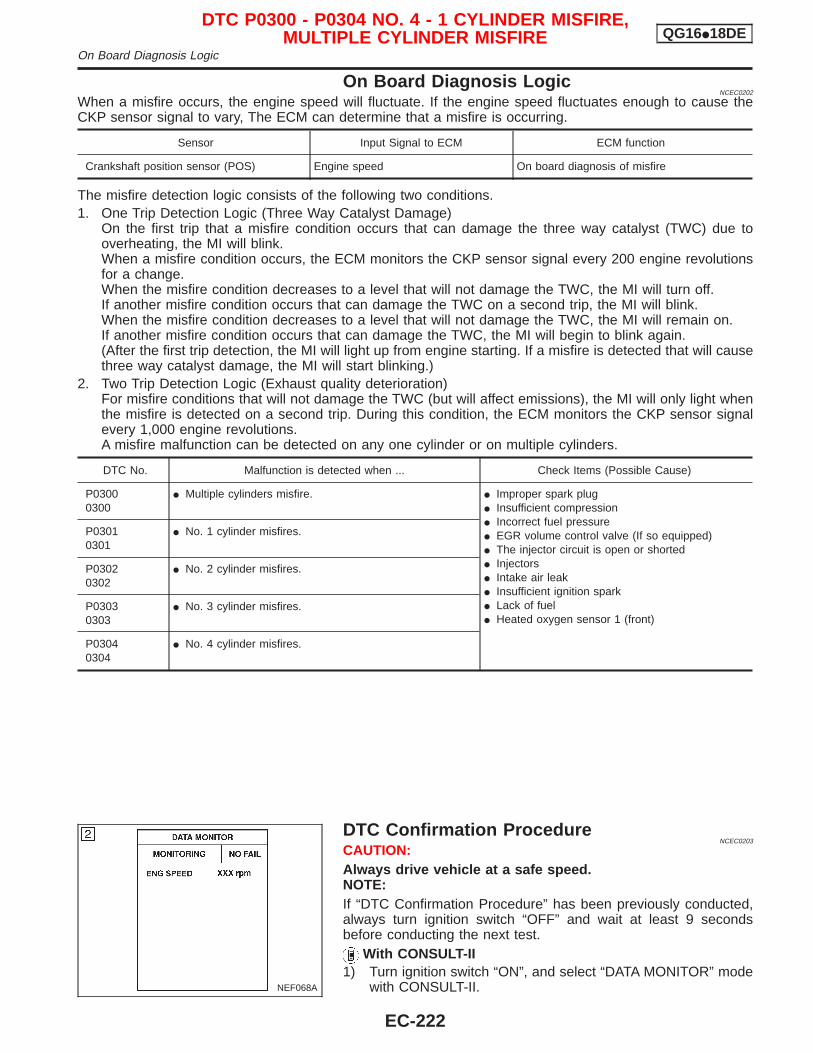
On Board Diagnosis LogicNCEC0202
When a misfire occurs, the engine speed will fluctuate. If the engine speed fluctuates enough to cause theCKP sensor signal to vary, The ECM can determine that a misfire is occurring.
Sensor Input Signal to ECM ECM function
Crankshaft position sensor (POS) Engine speed On board diagnosis of misfire
The misfire detection logic consists of the following two conditions.1. One Trip Detection Logic (Three Way Catalyst Damage)
On the first trip that a misfire condition occurs that can damage the three way catalyst (TWC) due tooverheating, the MI will blink.When a misfire condition occurs, the ECM monitors the CKP sensor signal every 200 engine revolutionsfor a change.When the misfire condition decreases to a level that will not damage the TWC, the MI will turn off.If another misfire condition occurs that can damage the TWC on a second trip, the MI will blink.When the misfire condition decreases to a level that will not damage the TWC, the MI will remain on.If another misfire condition occurs that can damage the TWC, the MI will begin to blink again.(After the first trip detection, the MI will light up from engine starting. If a misfire is detected that will causethree way catalyst damage, the MI will start blinking.)
2. Two Trip Detection Logic (Exhaust quality deterioration)For misfire conditions that will not damage the TWC (but will affect emissions), the MI will only light whenthe misfire is detected on a second trip. During this condition, the ECM monitors the CKP sensor signalevery 1,000 engine revolutions.A misfire malfunction can be detected on any one cylinder or on multiple cylinders.
DTC No. Malfunction is detected when ... Check Items (Possible Cause)
P03000300
I Multiple cylinders misfire. I Improper spark plugI Insufficient compressionI Incorrect fuel pressureI EGR volume control valve (If so equipped)I The injector circuit is open or shortedI InjectorsI Intake air leakI Insufficient ignition sparkI Lack of fuelI Heated oxygen sensor 1 (front)
P03010301
I No. 1 cylinder misfires.
P03020302
I No. 2 cylinder misfires.
P03030303
I No. 3 cylinder misfires.
P03040304
I No. 4 cylinder misfires.
DTC Confirmation ProcedureNCEC0203
CAUTION:Always drive vehicle at a safe speed.NOTE:If “DTC Confirmation Procedure” has been previously conducted,always turn ignition switch “OFF” and wait at least 9 secondsbefore conducting the next test.
With CONSULT-II1) Turn ignition switch “ON”, and select “DATA MONITOR” mode
with CONSULT-II.NEF068A
DTC P0300 - P0304 NO. 4 - 1 CYLINDER MISFIRE,MULTIPLE CYLINDER MISFIRE QG16I18DE
On Board Diagnosis Logic
EC-222
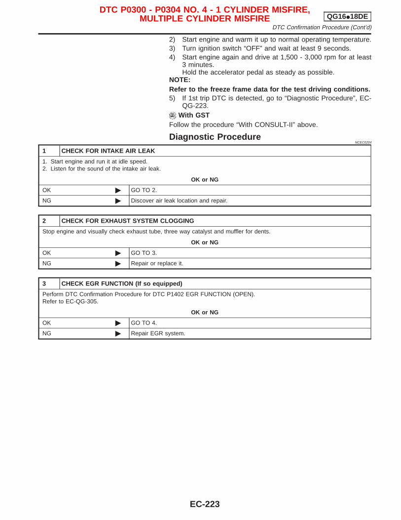
2) Start engine and warm it up to normal operating temperature.3) Turn ignition switch “OFF” and wait at least 9 seconds.4) Start engine again and drive at 1,500 - 3,000 rpm for at least
3 minutes.Hold the accelerator pedal as steady as possible.
NOTE:Refer to the freeze frame data for the test driving conditions.5) If 1st trip DTC is detected, go to “Diagnostic Procedure”, EC-
QG-223.With GST
Follow the procedure “With CONSULT-II” above.
Diagnostic ProcedureNCEC0204
1 CHECK FOR INTAKE AIR LEAK
1. Start engine and run it at idle speed.2. Listen for the sound of the intake air leak.
OK or NG
OK © GO TO 2.
NG © Discover air leak location and repair.
2 CHECK FOR EXHAUST SYSTEM CLOGGING
Stop engine and visually check exhaust tube, three way catalyst and muffler for dents.
OK or NG
OK © GO TO 3.
NG © Repair or replace it.
3 CHECK EGR FUNCTION (If so equipped)
Perform DTC Confirmation Procedure for DTC P1402 EGR FUNCTION (OPEN).Refer to EC-QG-305.
OK or NG
OK © GO TO 4.
NG © Repair EGR system.
DTC P0300 - P0304 NO. 4 - 1 CYLINDER MISFIRE,MULTIPLE CYLINDER MISFIRE QG16I18DE
DTC Confirmation Procedure (Cont’d)
EC-223
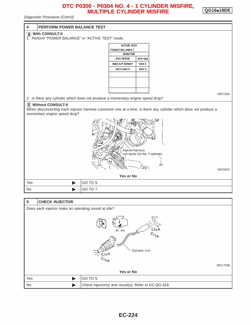
4 PERFORM POWER BALANCE TEST
With CONSULT-II1. Perform “POWER BALANCE” in “ACTIVE TEST” mode.
NEF105A
2. Is there any cylinder which does not produce a momentary engine speed drop?
Without CONSULT-IIWhen disconnecting each injector harness connector one at a time, is there any cylinder which does not produce amomentary engine speed drop?
SEF055X
Yes or No
Yes © GO TO 5.
No © GO TO 7.
5 CHECK INJECTOR
Does each injector make an operating sound at idle?
MEC703B
Yes or No
Yes © GO TO 6.
No © Check injector(s) and circuit(s). Refer to EC-QG-319.
DTC P0300 - P0304 NO. 4 - 1 CYLINDER MISFIRE,MULTIPLE CYLINDER MISFIRE QG16I18DE
Diagnostic Procedure (Cont’d)
EC-224
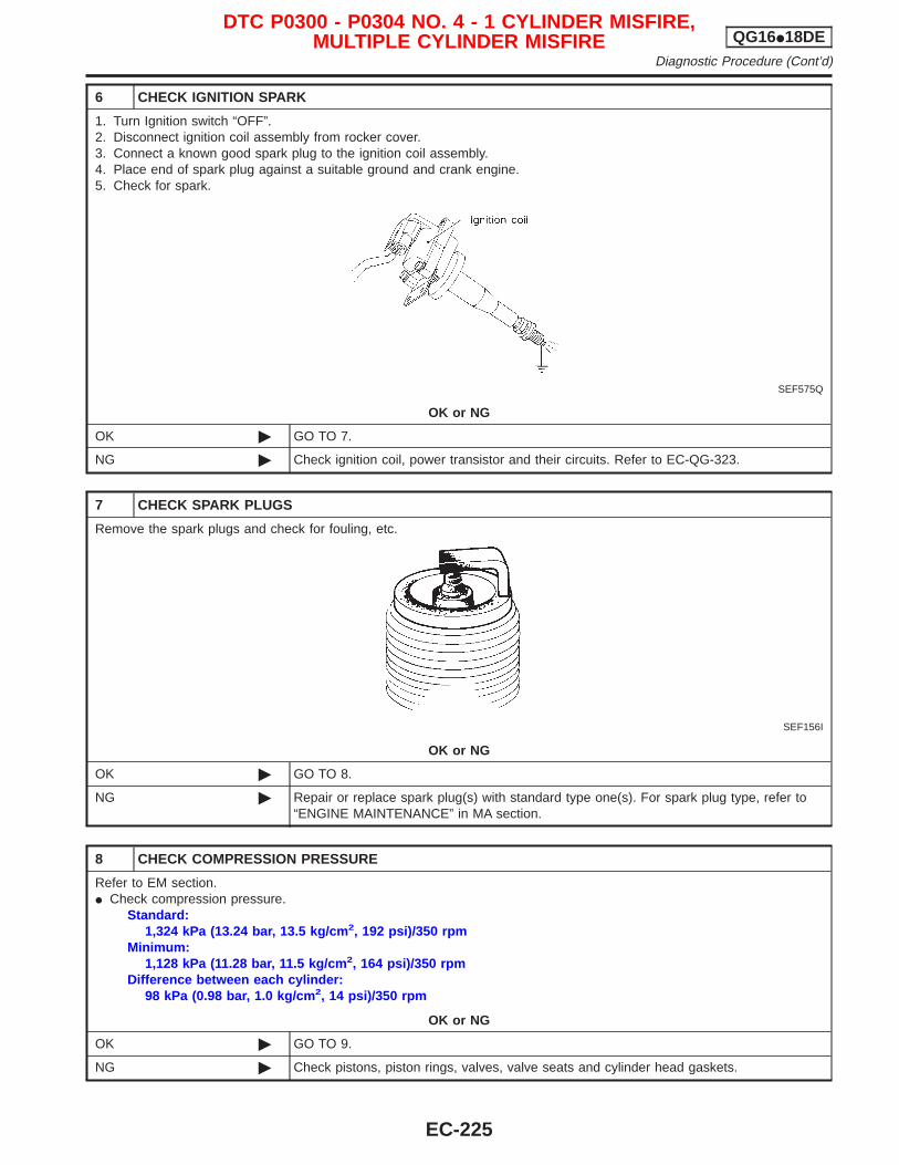
6 CHECK IGNITION SPARK
1. Turn Ignition switch “OFF”.2. Disconnect ignition coil assembly from rocker cover.3. Connect a known good spark plug to the ignition coil assembly.4. Place end of spark plug against a suitable ground and crank engine.5. Check for spark.
SEF575Q
OK or NG
OK © GO TO 7.
NG © Check ignition coil, power transistor and their circuits. Refer to EC-QG-323.
7 CHECK SPARK PLUGS
Remove the spark plugs and check for fouling, etc.
SEF156I
OK or NG
OK © GO TO 8.
NG © Repair or replace spark plug(s) with standard type one(s). For spark plug type, refer to“ENGINE MAINTENANCE” in MA section.
8 CHECK COMPRESSION PRESSURE
Refer to EM section.I Check compression pressure.
Standard:1,324 kPa (13.24 bar, 13.5 kg/cm 2, 192 psi)/350 rpm
Minimum:1,128 kPa (11.28 bar, 11.5 kg/cm 2, 164 psi)/350 rpm
Difference between each cylinder:98 kPa (0.98 bar, 1.0 kg/cm 2, 14 psi)/350 rpm
OK or NG
OK © GO TO 9.
NG © Check pistons, piston rings, valves, valve seats and cylinder head gaskets.
DTC P0300 - P0304 NO. 4 - 1 CYLINDER MISFIRE,MULTIPLE CYLINDER MISFIRE QG16I18DE
Diagnostic Procedure (Cont’d)
EC-225
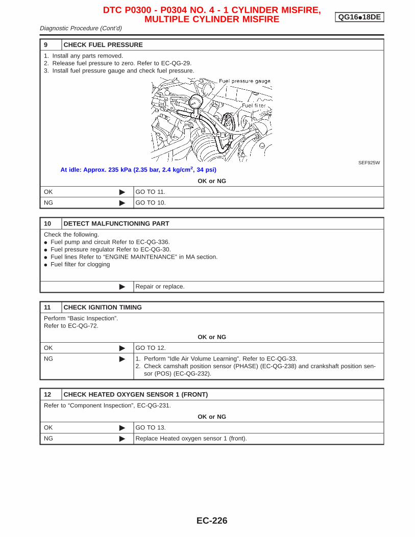
9 CHECK FUEL PRESSURE
1. Install any parts removed.2. Release fuel pressure to zero. Refer to EC-QG-29.3. Install fuel pressure gauge and check fuel pressure.
SEF925W
At idle: Approx. 235 kPa (2.35 bar, 2.4 kg/cm 2, 34 psi)
OK or NG
OK © GO TO 11.
NG © GO TO 10.
10 DETECT MALFUNCTIONING PART
Check the following.I Fuel pump and circuit Refer to EC-QG-336.I Fuel pressure regulator Refer to EC-QG-30.I Fuel lines Refer to “ENGINE MAINTENANCE” in MA section.I Fuel filter for clogging
© Repair or replace.
11 CHECK IGNITION TIMING
Perform “Basic Inspection”.Refer to EC-QG-72.
OK or NG
OK © GO TO 12.
NG © 1. Perform “Idle Air Volume Learning”. Refer to EC-QG-33.2. Check camshaft position sensor (PHASE) (EC-QG-238) and crankshaft position sen-
sor (POS) (EC-QG-232).
12 CHECK HEATED OXYGEN SENSOR 1 (FRONT)
Refer to “Component Inspection”, EC-QG-231.
OK or NG
OK © GO TO 13.
NG © Replace Heated oxygen sensor 1 (front).
DTC P0300 - P0304 NO. 4 - 1 CYLINDER MISFIRE,MULTIPLE CYLINDER MISFIRE QG16I18DE
Diagnostic Procedure (Cont’d)
EC-226
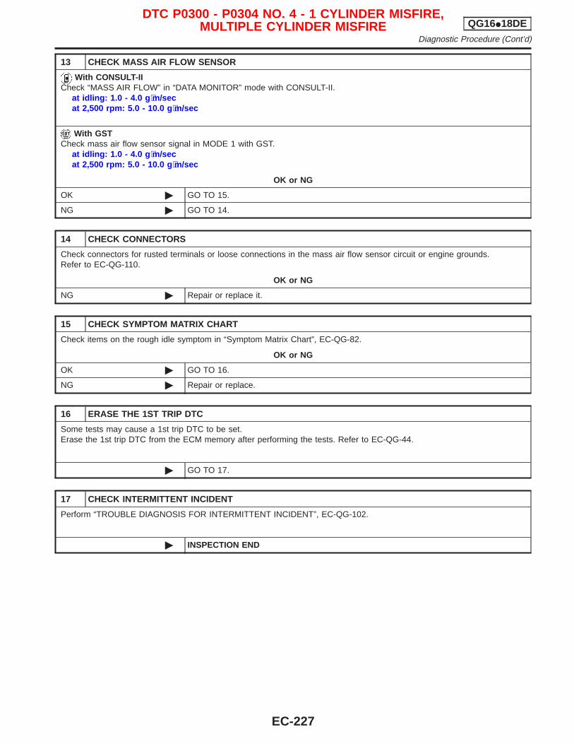
13 CHECK MASS AIR FLOW SENSOR
With CONSULT-IICheck “MASS AIR FLOW” in “DATA MONITOR” mode with CONSULT-II.
at idling: 1.0 - 4.0 g ⋅m/secat 2,500 rpm: 5.0 - 10.0 g ⋅m/sec
With GSTCheck mass air flow sensor signal in MODE 1 with GST.
at idling: 1.0 - 4.0 g ⋅m/secat 2,500 rpm: 5.0 - 10.0 g ⋅m/sec
OK or NG
OK © GO TO 15.
NG © GO TO 14.
14 CHECK CONNECTORS
Check connectors for rusted terminals or loose connections in the mass air flow sensor circuit or engine grounds.Refer to EC-QG-110.
OK or NG
NG © Repair or replace it.
15 CHECK SYMPTOM MATRIX CHART
Check items on the rough idle symptom in “Symptom Matrix Chart”, EC-QG-82.
OK or NG
OK © GO TO 16.
NG © Repair or replace.
16 ERASE THE 1ST TRIP DTC
Some tests may cause a 1st trip DTC to be set.Erase the 1st trip DTC from the ECM memory after performing the tests. Refer to EC-QG-44.
© GO TO 17.
17 CHECK INTERMITTENT INCIDENT
Perform “TROUBLE DIAGNOSIS FOR INTERMITTENT INCIDENT”, EC-QG-102.
© INSPECTION END
DTC P0300 - P0304 NO. 4 - 1 CYLINDER MISFIRE,MULTIPLE CYLINDER MISFIRE QG16I18DE
Diagnostic Procedure (Cont’d)
EC-227
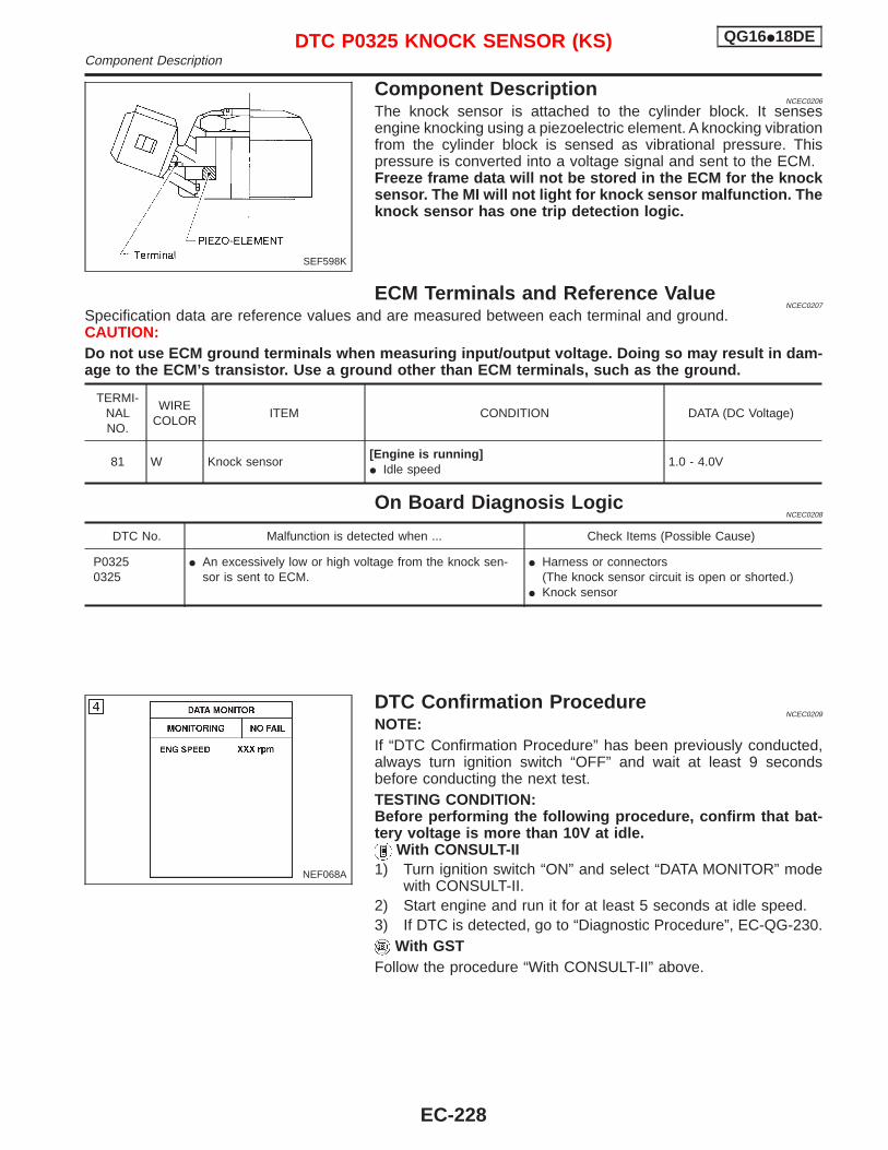
Component DescriptionNCEC0206
The knock sensor is attached to the cylinder block. It sensesengine knocking using a piezoelectric element. A knocking vibrationfrom the cylinder block is sensed as vibrational pressure. Thispressure is converted into a voltage signal and sent to the ECM.Freeze frame data will not be stored in the ECM for the knocksensor. The MI will not light for knock sensor malfunction. Theknock sensor has one trip detection logic.
ECM Terminals and Reference ValueNCEC0207
Specification data are reference values and are measured between each terminal and ground.CAUTION:Do not use ECM ground terminals when measuring input/output voltage. Doing so may result in dam-age to the ECM’s transistor. Use a ground other than ECM terminals, such as the ground.
TERMI-NALNO.
WIRECOLOR
ITEM CONDITION DATA (DC Voltage)
81 W Knock sensor[Engine is running]I Idle speed
1.0 - 4.0V
On Board Diagnosis LogicNCEC0208
DTC No. Malfunction is detected when ... Check Items (Possible Cause)
P03250325
I An excessively low or high voltage from the knock sen-sor is sent to ECM.
I Harness or connectors(The knock sensor circuit is open or shorted.)
I Knock sensor
DTC Confirmation ProcedureNCEC0209
NOTE:If “DTC Confirmation Procedure” has been previously conducted,always turn ignition switch “OFF” and wait at least 9 secondsbefore conducting the next test.TESTING CONDITION:Before performing the following procedure, confirm that bat-tery voltage is more than 10V at idle.
With CONSULT-II1) Turn ignition switch “ON” and select “DATA MONITOR” mode
with CONSULT-II.2) Start engine and run it for at least 5 seconds at idle speed.3) If DTC is detected, go to “Diagnostic Procedure”, EC-QG-230.
With GSTFollow the procedure “With CONSULT-II” above.
SEF598K
NEF068A
DTC P0325 KNOCK SENSOR (KS) QG16I18DEComponent Description
EC-228
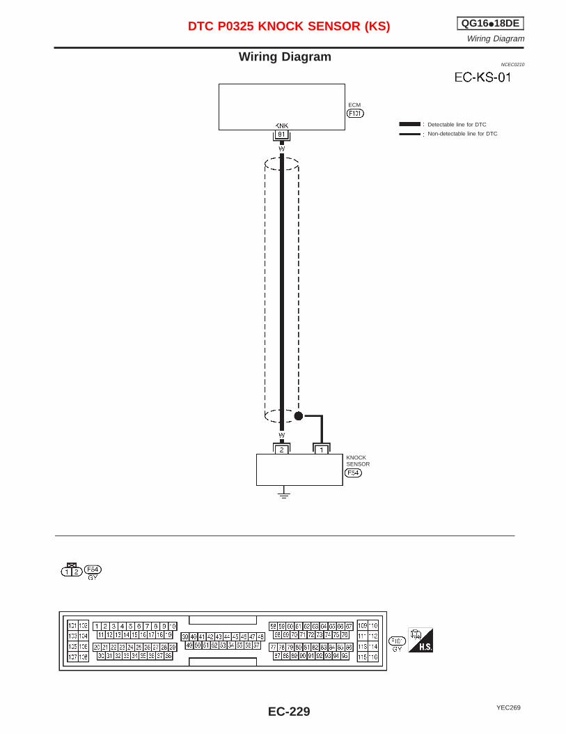
Wiring DiagramNCEC0210
YEC269
Detectable line for DTC
Non-detectable line for DTC
ECM
KNOCKSENSOR
DTC P0325 KNOCK SENSOR (KS) QG16I18DEWiring Diagram
EC-229
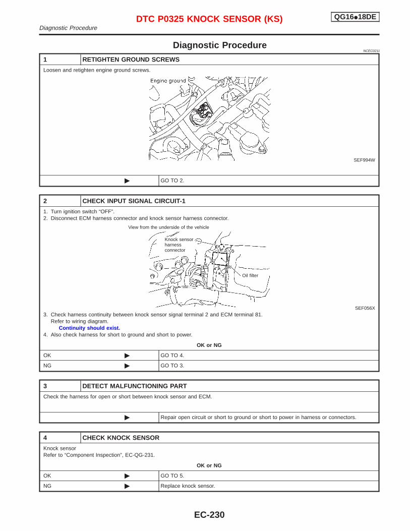
Diagnostic ProcedureNCEC0211
1 RETIGHTEN GROUND SCREWS
Loosen and retighten engine ground screws.
SEF994W
© GO TO 2.
2 CHECK INPUT SIGNAL CIRCUIT-1
1. Turn ignition switch “OFF”.2. Disconnect ECM harness connector and knock sensor harness connector.
SEF056X3. Check harness continuity between knock sensor signal terminal 2 and ECM terminal 81.
Refer to wiring diagram.Continuity should exist.
4. Also check harness for short to ground and short to power.
OK or NG
OK © GO TO 4.
NG © GO TO 3.
3 DETECT MALFUNCTIONING PART
Check the harness for open or short between knock sensor and ECM.
© Repair open circuit or short to ground or short to power in harness or connectors.
4 CHECK KNOCK SENSOR
Knock sensorRefer to “Component Inspection”, EC-QG-231.
OK or NG
OK © GO TO 5.
NG © Replace knock sensor.
View from the underside of the vehicle
Knock sensorharnessconnector
Oil filter
DTC P0325 KNOCK SENSOR (KS) QG16I18DEDiagnostic Procedure
EC-230
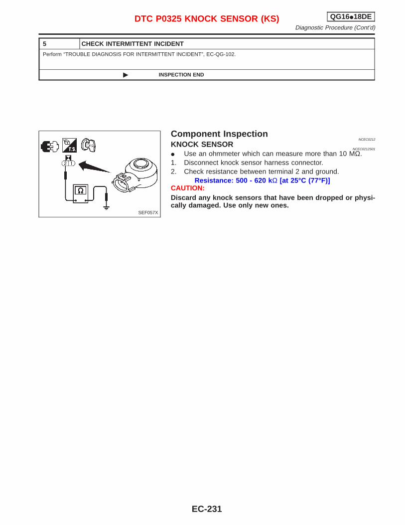
5 CHECK INTERMITTENT INCIDENT
Perform “TROUBLE DIAGNOSIS FOR INTERMITTENT INCIDENT”, EC-QG-102.
© INSPECTION END
Component InspectionNCEC0212
KNOCK SENSORNCEC0212S01
I Use an ohmmeter which can measure more than 10 MΩ.1. Disconnect knock sensor harness connector.2. Check resistance between terminal 2 and ground.
Resistance: 500 - 620 k Ω [at 25°C (77°F)]CAUTION:Discard any knock sensors that have been dropped or physi-cally damaged. Use only new ones.
SEF057X
DTC P0325 KNOCK SENSOR (KS) QG16I18DEDiagnostic Procedure (Cont’d)
EC-231
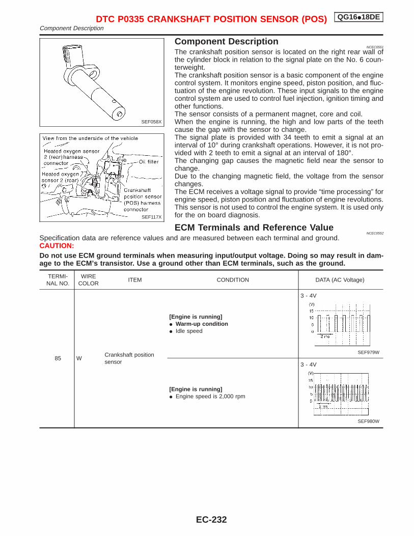
Component DescriptionNCEC0551
The crankshaft position sensor is located on the right rear wall ofthe cylinder block in relation to the signal plate on the No. 6 coun-terweight.The crankshaft position sensor is a basic component of the enginecontrol system. It monitors engine speed, piston position, and fluc-tuation of the engine revolution. These input signals to the enginecontrol system are used to control fuel injection, ignition timing andother functions.The sensor consists of a permanent magnet, core and coil.When the engine is running, the high and low parts of the teethcause the gap with the sensor to change.The signal plate is provided with 34 teeth to emit a signal at aninterval of 10° during crankshaft operations. However, it is not pro-vided with 2 teeth to emit a signal at an interval of 180°.The changing gap causes the magnetic field near the sensor tochange.Due to the changing magnetic field, the voltage from the sensorchanges.The ECM receives a voltage signal to provide “time processing” forengine speed, piston position and fluctuation of engine revolutions.This sensor is not used to control the engine system. It is used onlyfor the on board diagnosis.
ECM Terminals and Reference ValueNCEC0552
Specification data are reference values and are measured between each terminal and ground.CAUTION:Do not use ECM ground terminals when measuring input/output voltage. Doing so may result in dam-age to the ECM’s transistor. Use a ground other than ECM terminals, such as the ground.
TERMI-NAL NO.
WIRECOLOR
ITEM CONDITION DATA (AC Voltage)
85 WCrankshaft positionsensor
[Engine is running]I Warm-up conditionI Idle speed
3 - 4V
SEF979W
[Engine is running]I Engine speed is 2,000 rpm
3 - 4V
SEF980W
SEF058X
SEF117X
DTC P0335 CRANKSHAFT POSITION SENSOR (POS) QG16I18DEComponent Description
EC-232
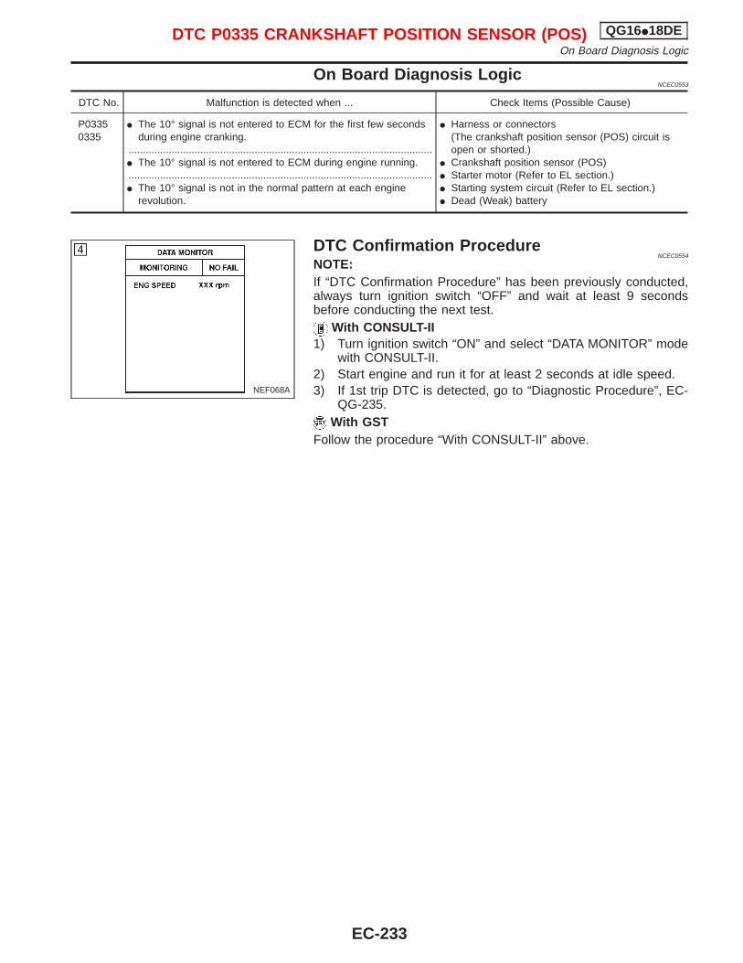
On Board Diagnosis LogicNCEC0553
DTC No. Malfunction is detected when ... Check Items (Possible Cause)
P03350335
I The 10° signal is not entered to ECM for the first few secondsduring engine cranking.
..........................................................................................................I The 10° signal is not entered to ECM during engine running...........................................................................................................I The 10° signal is not in the normal pattern at each engine
revolution.
I Harness or connectors(The crankshaft position sensor (POS) circuit isopen or shorted.)
I Crankshaft position sensor (POS)I Starter motor (Refer to EL section.)I Starting system circuit (Refer to EL section.)I Dead (Weak) battery
DTC Confirmation ProcedureNCEC0554
NOTE:If “DTC Confirmation Procedure” has been previously conducted,always turn ignition switch “OFF” and wait at least 9 secondsbefore conducting the next test.
With CONSULT-II1) Turn ignition switch “ON” and select “DATA MONITOR” mode
with CONSULT-II.2) Start engine and run it for at least 2 seconds at idle speed.3) If 1st trip DTC is detected, go to “Diagnostic Procedure”, EC-
QG-235.With GST
Follow the procedure “With CONSULT-II” above.
NEF068A
DTC P0335 CRANKSHAFT POSITION SENSOR (POS) QG16I18DEOn Board Diagnosis Logic
EC-233
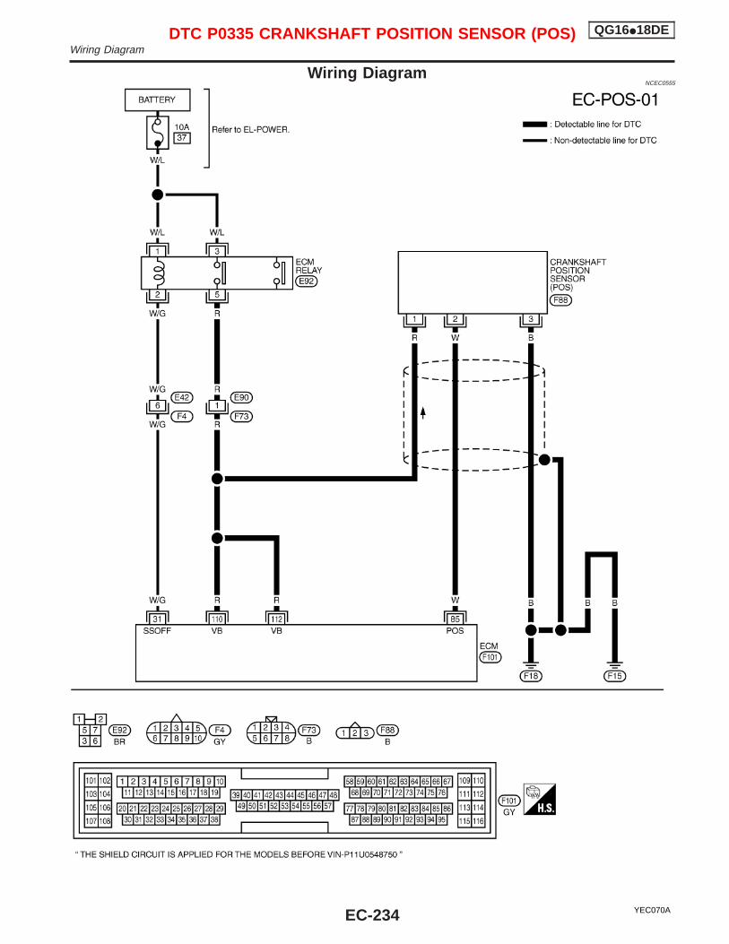
Wiring DiagramNCEC0555
YEC070A
DTC P0335 CRANKSHAFT POSITION SENSOR (POS) QG16I18DEWiring Diagram
EC-234
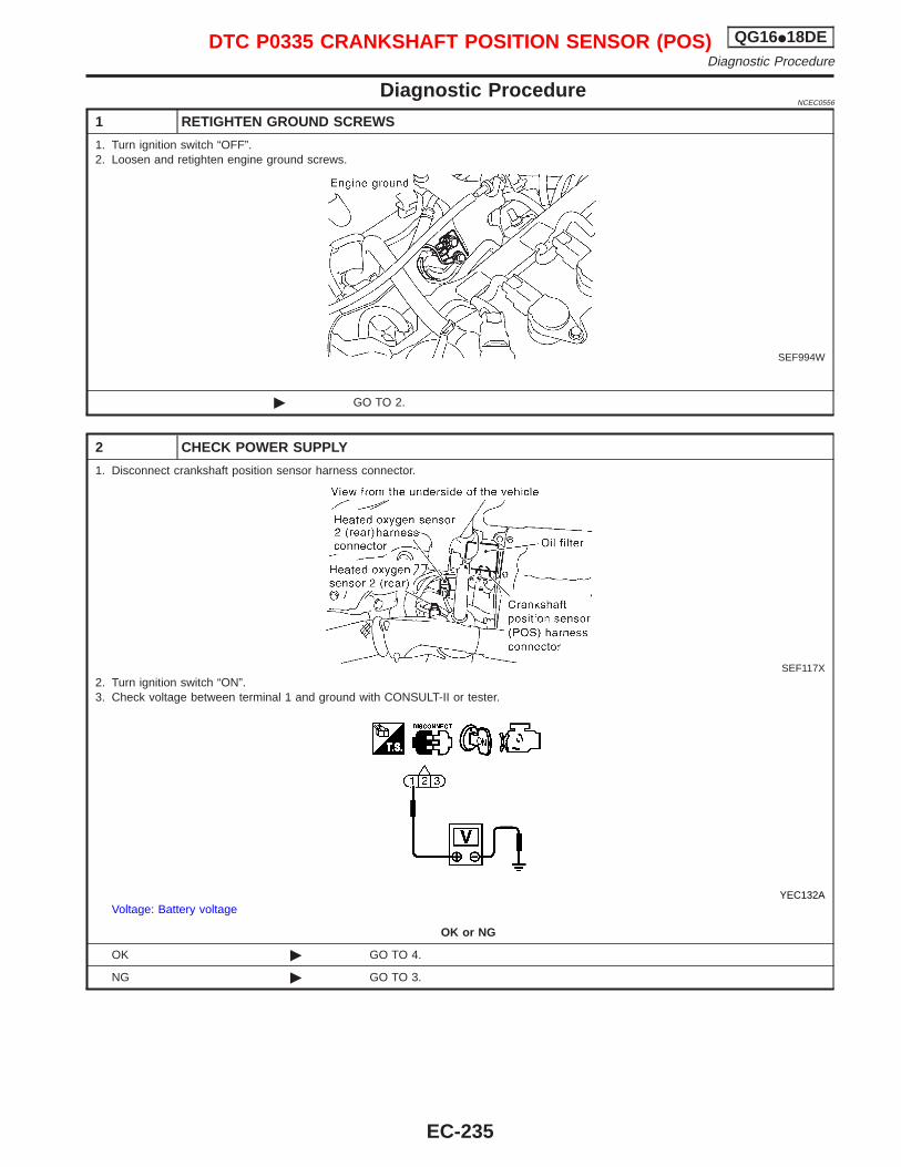
Diagnostic ProcedureNCEC0556
1 RETIGHTEN GROUND SCREWS
1. Turn ignition switch “OFF”.2. Loosen and retighten engine ground screws.
SEF994W
© GO TO 2.
2 CHECK POWER SUPPLY
1. Disconnect crankshaft position sensor harness connector.
SEF117X2. Turn ignition switch “ON”.3. Check voltage between terminal 1 and ground with CONSULT-II or tester.
YEC132AVoltage: Battery voltage
OK or NG
OK © GO TO 4.
NG © GO TO 3.
DTC P0335 CRANKSHAFT POSITION SENSOR (POS) QG16I18DEDiagnostic Procedure
EC-235
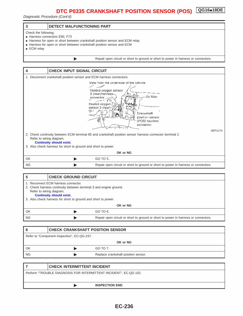
3 DETECT MALFUNCTIONING PART
Check the following.I Harness connectors E90, F73I Harness for open or short between crankshaft position sensor and ECM relayI Harness for open or short between crankshaft position sensor and ECMI ECM relay
© Repair open circuit or short to ground or short to power in harness or connectors.
4 CHECK INPUT SIGNAL CIRCUIT
1. Disconnect crankshaft position sensor and ECM harness connectors.
SEF117X2. Check continuity between ECM terminal 85 and crankshaft position sensor harness connector terminal 2.
Refer to wiring diagram.Continuity should exist.
3. Also check harness for short to ground and short to power.
OK or NG
OK © GO TO 5.
NG © Repair open circuit or short to ground or short to power in harness or connectors.
5 CHECK GROUND CIRCUIT
1. Reconnect ECM harness connector.2. Check harness continuity between terminal 3 and engine ground.
Refer to wiring diagram.Continuity should exist.
3. Also check harness for short to ground and short to power.
OK or NG
OK © GO TO 6.
NG © Repair open circuit or short to ground or short to power in harness or connectors.
6 CHECK CRANKSHAFT POSITION SENSOR
Refer to “Component Inspection”, EC-QG-237.
OK or NG
OK © GO TO 7.
NG © Replace crankshaft position sensor.
7 CHECK INTERMITTENT INCIDENT
Perform “TROUBLE DIAGNOSIS FOR INTERMITTENT INCIDENT”, EC-QG-102.
© INSPECTION END
DTC P0335 CRANKSHAFT POSITION SENSOR (POS) QG16I18DEDiagnostic Procedure (Cont’d)
EC-236
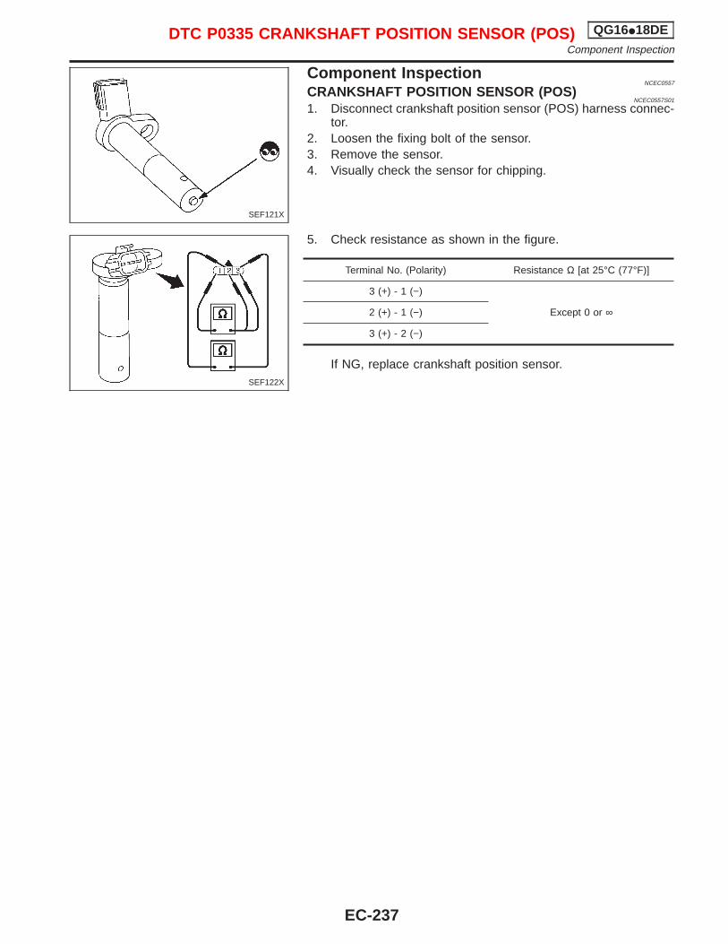
Component InspectionNCEC0557
CRANKSHAFT POSITION SENSOR (POS)NCEC0557S01
1. Disconnect crankshaft position sensor (POS) harness connec-tor.
2. Loosen the fixing bolt of the sensor.3. Remove the sensor.4. Visually check the sensor for chipping.
5. Check resistance as shown in the figure.
Terminal No. (Polarity) Resistance Ω [at 25°C (77°F)]
3 (+) - 1 (−)
Except 0 or ∞2 (+) - 1 (−)
3 (+) - 2 (−)
If NG, replace crankshaft position sensor.
SEF121X
SEF122X
DTC P0335 CRANKSHAFT POSITION SENSOR (POS) QG16I18DEComponent Inspection
EC-237
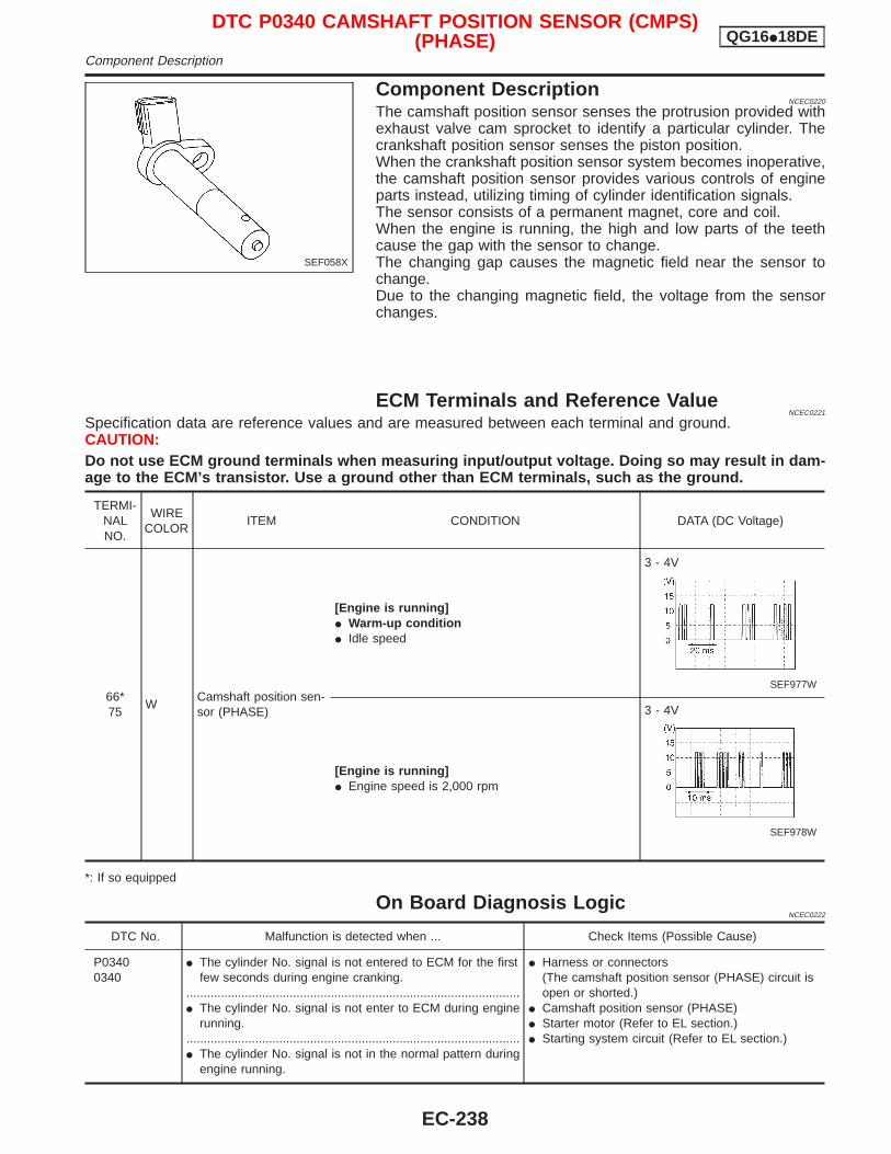
Component DescriptionNCEC0220
The camshaft position sensor senses the protrusion provided withexhaust valve cam sprocket to identify a particular cylinder. Thecrankshaft position sensor senses the piston position.When the crankshaft position sensor system becomes inoperative,the camshaft position sensor provides various controls of engineparts instead, utilizing timing of cylinder identification signals.The sensor consists of a permanent magnet, core and coil.When the engine is running, the high and low parts of the teethcause the gap with the sensor to change.The changing gap causes the magnetic field near the sensor tochange.Due to the changing magnetic field, the voltage from the sensorchanges.
ECM Terminals and Reference ValueNCEC0221
Specification data are reference values and are measured between each terminal and ground.CAUTION:Do not use ECM ground terminals when measuring input/output voltage. Doing so may result in dam-age to the ECM’s transistor. Use a ground other than ECM terminals, such as the ground.
TERMI-NALNO.
WIRECOLOR
ITEM CONDITION DATA (DC Voltage)
66*75
WCamshaft position sen-sor (PHASE)
[Engine is running]I Warm-up conditionI Idle speed
3 - 4V
SEF977W
[Engine is running]I Engine speed is 2,000 rpm
3 - 4V
SEF978W
*: If so equipped
On Board Diagnosis LogicNCEC0222
DTC No. Malfunction is detected when ... Check Items (Possible Cause)
P03400340
I The cylinder No. signal is not entered to ECM for the firstfew seconds during engine cranking.
.................................................................................................I The cylinder No. signal is not enter to ECM during engine
running..................................................................................................I The cylinder No. signal is not in the normal pattern during
engine running.
I Harness or connectors(The camshaft position sensor (PHASE) circuit isopen or shorted.)
I Camshaft position sensor (PHASE)I Starter motor (Refer to EL section.)I Starting system circuit (Refer to EL section.)
SEF058X
DTC P0340 CAMSHAFT POSITION SENSOR (CMPS)(PHASE) QG16I18DE
Component Description
EC-238
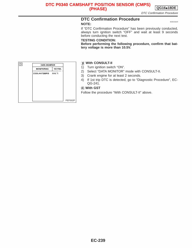
DTC Confirmation ProcedureNCEC0223
NOTE:If “DTC Confirmation Procedure” has been previously conducted,always turn ignition switch “OFF” and wait at least 9 secondsbefore conducting the next test.TESTING CONDITION:Before performing the following procedure, confirm that bat-tery voltage is more than 10.5V.
With CONSULT-II1) Turn ignition switch “ON”.2) Select “DATA MONITOR” mode with CONSULT-II.3) Crank engine for at least 2 seconds.4) If 1st trip DTC is detected, go to “Diagnostic Procedure”, EC-
QG-241.With GST
Follow the procedure “With CONSULT-II” above.
PEF002P
DTC P0340 CAMSHAFT POSITION SENSOR (CMPS)(PHASE) QG16I18DE
DTC Confirmation Procedure
EC-239
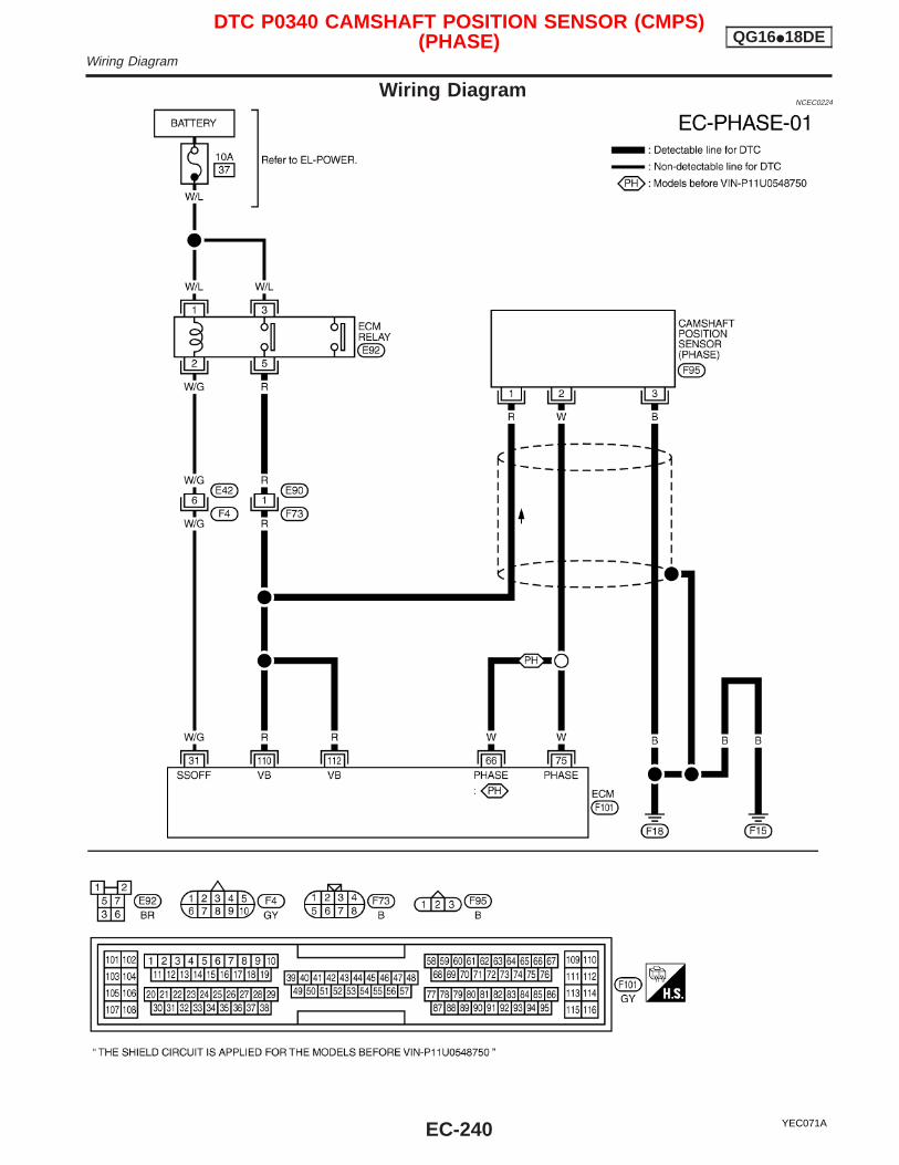
Wiring DiagramNCEC0224
YEC071A
DTC P0340 CAMSHAFT POSITION SENSOR (CMPS)(PHASE) QG16I18DE
Wiring Diagram
EC-240
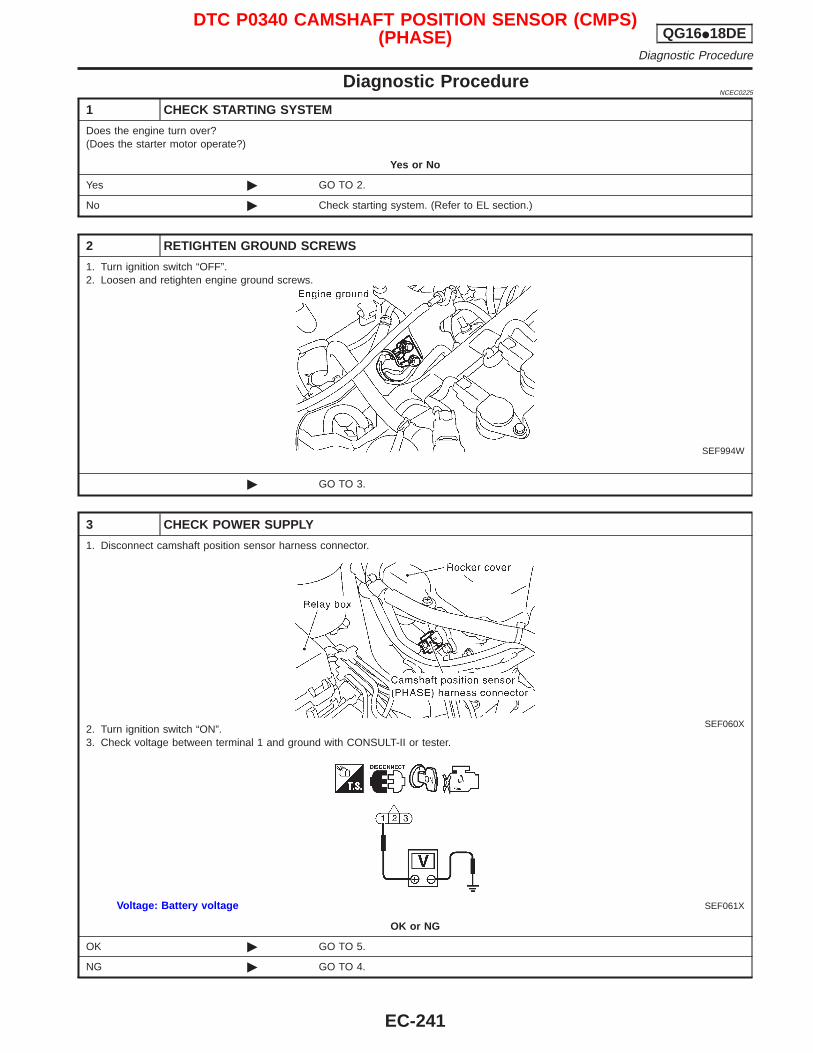
Diagnostic ProcedureNCEC0225
1 CHECK STARTING SYSTEM
Does the engine turn over?(Does the starter motor operate?)
Yes or No
Yes © GO TO 2.
No © Check starting system. (Refer to EL section.)
2 RETIGHTEN GROUND SCREWS
1. Turn ignition switch “OFF”.2. Loosen and retighten engine ground screws.
SEF994W
© GO TO 3.
3 CHECK POWER SUPPLY
1. Disconnect camshaft position sensor harness connector.
SEF060X2. Turn ignition switch “ON”.3. Check voltage between terminal 1 and ground with CONSULT-II or tester.
SEF061XVoltage: Battery voltage
OK or NG
OK © GO TO 5.
NG © GO TO 4.
DTC P0340 CAMSHAFT POSITION SENSOR (CMPS)(PHASE) QG16I18DE
Diagnostic Procedure
EC-241
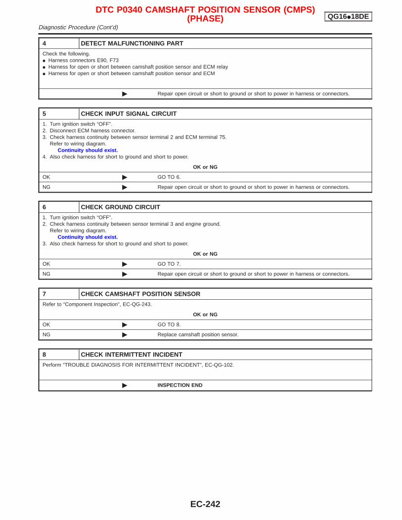
4 DETECT MALFUNCTIONING PART
Check the following.I Harness connectors E90, F73I Harness for open or short between camshaft position sensor and ECM relayI Harness for open or short between camshaft position sensor and ECM
© Repair open circuit or short to ground or short to power in harness or connectors.
5 CHECK INPUT SIGNAL CIRCUIT
1. Turn ignition switch “OFF”.2. Disconnect ECM harness connector.3. Check harness continuity between sensor terminal 2 and ECM terminal 75.
Refer to wiring diagram.Continuity should exist.
4. Also check harness for short to ground and short to power.
OK or NG
OK © GO TO 6.
NG © Repair open circuit or short to ground or short to power in harness or connectors.
6 CHECK GROUND CIRCUIT
1. Turn ignition switch “OFF”.2. Check harness continuity between sensor terminal 3 and engine ground.
Refer to wiring diagram.Continuity should exist.
3. Also check harness for short to ground and short to power.
OK or NG
OK © GO TO 7.
NG © Repair open circuit or short to ground or short to power in harness or connectors.
7 CHECK CAMSHAFT POSITION SENSOR
Refer to “Component Inspection”, EC-QG-243.
OK or NG
OK © GO TO 8.
NG © Replace camshaft position sensor.
8 CHECK INTERMITTENT INCIDENT
Perform “TROUBLE DIAGNOSIS FOR INTERMITTENT INCIDENT”, EC-QG-102.
© INSPECTION END
DTC P0340 CAMSHAFT POSITION SENSOR (CMPS)(PHASE) QG16I18DE
Diagnostic Procedure (Cont’d)
EC-242
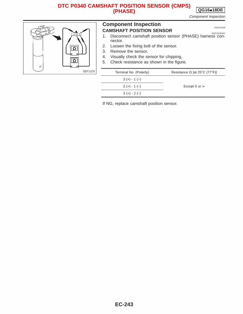
Component Inspection=NCEC0226
CAMSHAFT POSITION SENSORNCEC0226S01
1. Disconnect camshaft position sensor (PHASE) harness con-nector.
2. Loosen the fixing bolt of the sensor.3. Remove the sensor.4. Visually check the sensor for chipping.5. Check resistance as shown in the figure.
Terminal No. (Polarity) Resistance Ω [at 25°C (77°F)]
3 (+) - 1 (−)
Except 0 or ∞2 (+) - 1 (−)
3 (+) - 2 (−)
If NG, replace camshaft position sensor.
SEF122X
DTC P0340 CAMSHAFT POSITION SENSOR (CMPS)(PHASE) QG16I18DE
Component Inspection
EC-243
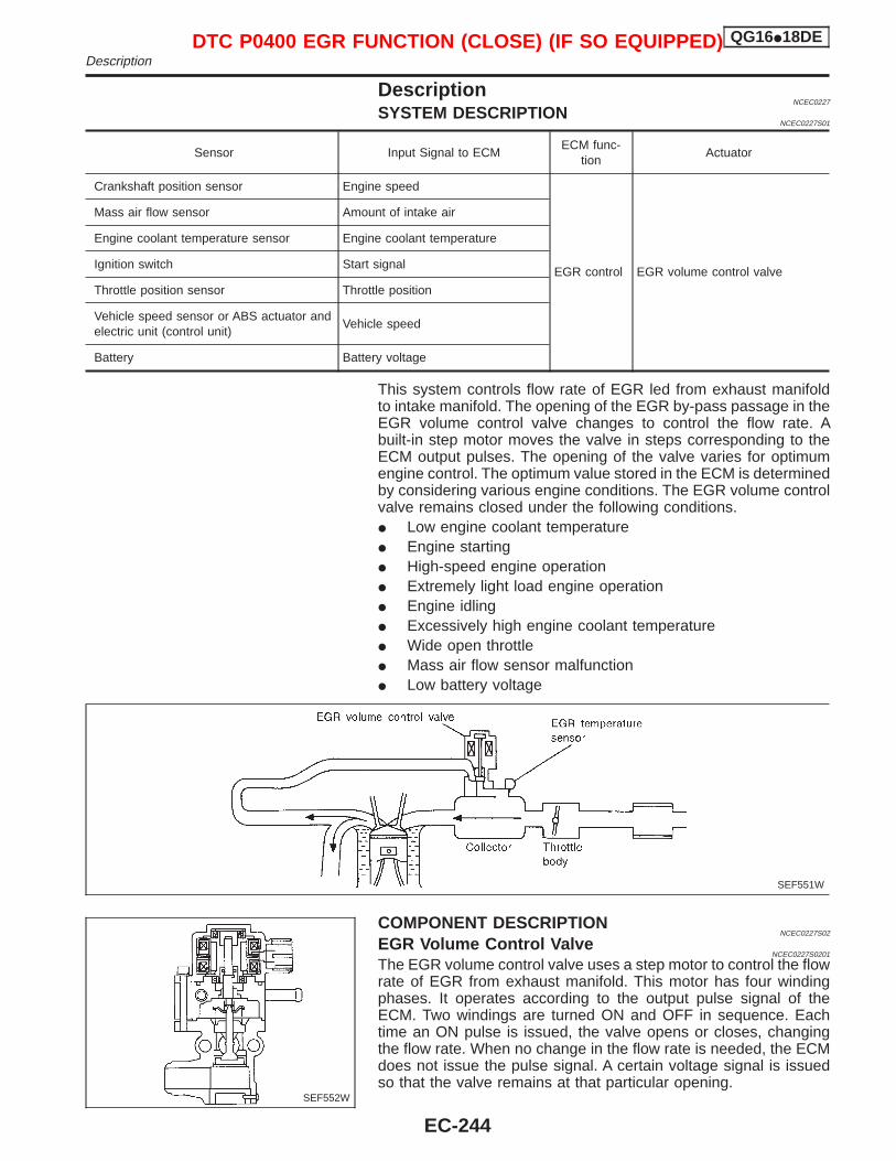
DescriptionNCEC0227
SYSTEM DESCRIPTIONNCEC0227S01
Sensor Input Signal to ECMECM func-
tionActuator
Crankshaft position sensor Engine speed
EGR control EGR volume control valve
Mass air flow sensor Amount of intake air
Engine coolant temperature sensor Engine coolant temperature
Ignition switch Start signal
Throttle position sensor Throttle position
Vehicle speed sensor or ABS actuator andelectric unit (control unit)
Vehicle speed
Battery Battery voltage
This system controls flow rate of EGR led from exhaust manifoldto intake manifold. The opening of the EGR by-pass passage in theEGR volume control valve changes to control the flow rate. Abuilt-in step motor moves the valve in steps corresponding to theECM output pulses. The opening of the valve varies for optimumengine control. The optimum value stored in the ECM is determinedby considering various engine conditions. The EGR volume controlvalve remains closed under the following conditions.I Low engine coolant temperatureI Engine startingI High-speed engine operationI Extremely light load engine operationI Engine idlingI Excessively high engine coolant temperatureI Wide open throttleI Mass air flow sensor malfunctionI Low battery voltage
COMPONENT DESCRIPTIONNCEC0227S02
EGR Volume Control ValveNCEC0227S0201
The EGR volume control valve uses a step motor to control the flowrate of EGR from exhaust manifold. This motor has four windingphases. It operates according to the output pulse signal of theECM. Two windings are turned ON and OFF in sequence. Eachtime an ON pulse is issued, the valve opens or closes, changingthe flow rate. When no change in the flow rate is needed, the ECMdoes not issue the pulse signal. A certain voltage signal is issuedso that the valve remains at that particular opening.
SEF551W
SEF552W
DTC P0400 EGR FUNCTION (CLOSE) (IF SO EQUIPPED) QG16I18DEDescription
EC-244
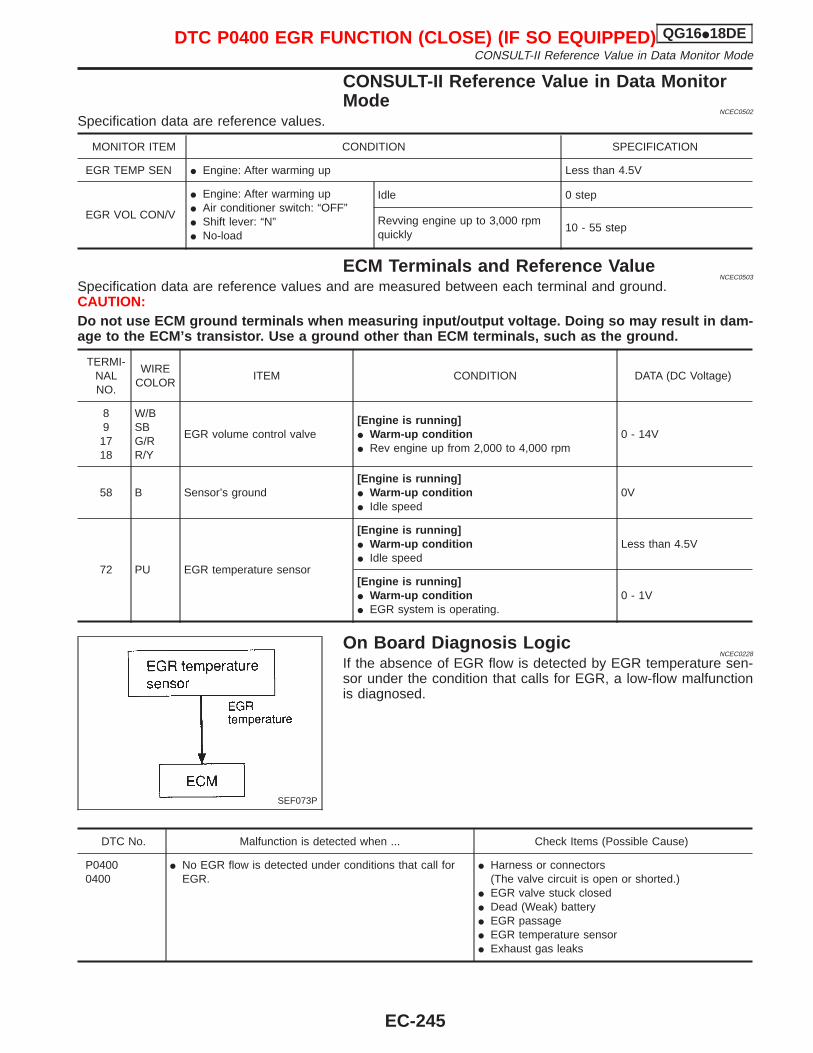
CONSULT-II Reference Value in Data MonitorMode
NCEC0502
Specification data are reference values.
MONITOR ITEM CONDITION SPECIFICATION
EGR TEMP SEN I Engine: After warming up Less than 4.5V
EGR VOL CON/V
I Engine: After warming upI Air conditioner switch: “OFF”I Shift lever: “N”I No-load
Idle 0 step
Revving engine up to 3,000 rpmquickly
10 - 55 step
ECM Terminals and Reference ValueNCEC0503
Specification data are reference values and are measured between each terminal and ground.CAUTION:Do not use ECM ground terminals when measuring input/output voltage. Doing so may result in dam-age to the ECM’s transistor. Use a ground other than ECM terminals, such as the ground.
TERMI-NALNO.
WIRECOLOR
ITEM CONDITION DATA (DC Voltage)
89
1718
W/BSBG/RR/Y
EGR volume control valve[Engine is running]I Warm-up conditionI Rev engine up from 2,000 to 4,000 rpm
0 - 14V
58 B Sensor’s ground[Engine is running]I Warm-up conditionI Idle speed
0V
72 PU EGR temperature sensor
[Engine is running]I Warm-up conditionI Idle speed
Less than 4.5V
[Engine is running]I Warm-up conditionI EGR system is operating.
0 - 1V
On Board Diagnosis LogicNCEC0228
If the absence of EGR flow is detected by EGR temperature sen-sor under the condition that calls for EGR, a low-flow malfunctionis diagnosed.
DTC No. Malfunction is detected when ... Check Items (Possible Cause)
P04000400
I No EGR flow is detected under conditions that call forEGR.
I Harness or connectors(The valve circuit is open or shorted.)
I EGR valve stuck closedI Dead (Weak) batteryI EGR passageI EGR temperature sensorI Exhaust gas leaks
SEF073P
DTC P0400 EGR FUNCTION (CLOSE) (IF SO EQUIPPED) QG16I18DECONSULT-II Reference Value in Data Monitor Mode
EC-245
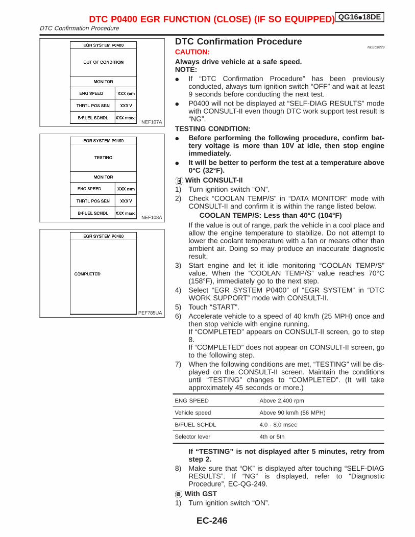
DTC Confirmation ProcedureNCEC0229
CAUTION:Always drive vehicle at a safe speed.NOTE:I If “DTC Confirmation Procedure” has been previously
conducted, always turn ignition switch “OFF” and wait at least9 seconds before conducting the next test.
I P0400 will not be displayed at “SELF-DIAG RESULTS” modewith CONSULT-II even though DTC work support test result is“NG”.
TESTING CONDITION:I Before performing the following procedure, confirm bat-
tery voltage is more than 10V at idle, then stop engineimmediately.
I It will be better to perform the test at a temperature above0°C (32°F).
With CONSULT-II1) Turn ignition switch “ON”.2) Check “COOLAN TEMP/S” in “DATA MONITOR” mode with
CONSULT-II and confirm it is within the range listed below.COOLAN TEMP/S: Less than 40°C (104°F)
If the value is out of range, park the vehicle in a cool place andallow the engine temperature to stabilize. Do not attempt tolower the coolant temperature with a fan or means other thanambient air. Doing so may produce an inaccurate diagnosticresult.
3) Start engine and let it idle monitoring “COOLAN TEMP/S”value. When the “COOLAN TEMP/S” value reaches 70°C(158°F), immediately go to the next step.
4) Select “EGR SYSTEM P0400” of “EGR SYSTEM” in “DTCWORK SUPPORT” mode with CONSULT-II.
5) Touch “START”.6) Accelerate vehicle to a speed of 40 km/h (25 MPH) once and
then stop vehicle with engine running.If “COMPLETED” appears on CONSULT-II screen, go to step8.If “COMPLETED” does not appear on CONSULT-II screen, goto the following step.
7) When the following conditions are met, “TESTING” will be dis-played on the CONSULT-II screen. Maintain the conditionsuntil “TESTING” changes to “COMPLETED”. (It will takeapproximately 45 seconds or more.)
ENG SPEED Above 2,400 rpm
Vehicle speed Above 90 km/h (56 MPH)
B/FUEL SCHDL 4.0 - 8.0 msec
Selector lever 4th or 5th
If “TESTING” is not displayed after 5 minutes, retry fromstep 2.
8) Make sure that “OK” is displayed after touching “SELF-DIAGRESULTS”. If “NG” is displayed, refer to “DiagnosticProcedure”, EC-QG-249.
With GST1) Turn ignition switch “ON”.
NEF107A
NEF108A
PEF785UA
DTC P0400 EGR FUNCTION (CLOSE) (IF SO EQUIPPED) QG16I18DEDTC Confirmation Procedure
EC-246
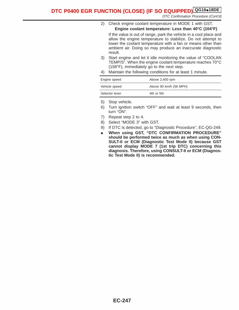
2) Check engine coolant temperature in MODE 1 with GST.Engine coolant temperature: Less than 40°C (104°F)
If the value is out of range, park the vehicle in a cool place andallow the engine temperature to stabilize. Do not attempt tolower the coolant temperature with a fan or means other thanambient air. Doing so may produce an inaccurate diagnosticresult.
3) Start engine and let it idle monitoring the value of “COOLANTEMP/S”. When the engine coolant temperature reaches 70°C(158°F), immediately go to the next step.
4) Maintain the following conditions for at least 1 minute.
Engine speed Above 2,400 rpm
Vehicle speed Above 90 km/h (56 MPH)
Selector lever 4th or 5th
5) Stop vehicle.6) Turn ignition switch “OFF” and wait at least 9 seconds, then
turn “ON”.7) Repeat step 2 to 4.8) Select “MODE 3” with GST.9) If DTC is detected, go to “Diagnostic Procedure”, EC-QG-249.I When using GST, “DTC CONFIRMATION PROCEDURE”
should be performed twice as much as when using CON-SULT-II or ECM (Diagnostic Test Mode II) because GSTcannot display MODE 7 (1st trip DTC) concerning thisdiagnosis. Therefore, using CONSULT-II or ECM (Diagnos-tic Test Mode II) is recommended.
DTC P0400 EGR FUNCTION (CLOSE) (IF SO EQUIPPED) QG16I18DEDTC Confirmation Procedure (Cont’d)
EC-247

Wiring DiagramNCEC0231
YEC072A
DTC P0400 EGR FUNCTION (CLOSE) (IF SO EQUIPPED) QG16I18DEWiring Diagram
EC-248
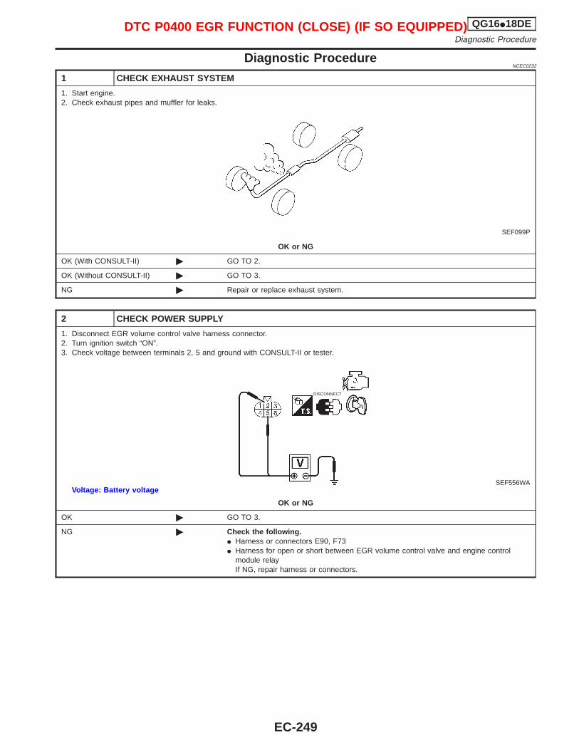
Diagnostic ProcedureNCEC0232
1 CHECK EXHAUST SYSTEM
1. Start engine.2. Check exhaust pipes and muffler for leaks.
SEF099P
OK or NG
OK (With CONSULT-II) © GO TO 2.
OK (Without CONSULT-II) © GO TO 3.
NG © Repair or replace exhaust system.
2 CHECK POWER SUPPLY
1. Disconnect EGR volume control valve harness connector.2. Turn ignition switch “ON”.3. Check voltage between terminals 2, 5 and ground with CONSULT-II or tester.
DISCONNECT
SEF556WAVoltage: Battery voltage
OK or NG
OK © GO TO 3.
NG © Check the following.I Harness or connectors E90, F73I Harness for open or short between EGR volume control valve and engine control
module relayIf NG, repair harness or connectors.
DTC P0400 EGR FUNCTION (CLOSE) (IF SO EQUIPPED) QG16I18DEDiagnostic Procedure
EC-249
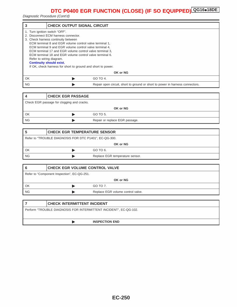
3 CHECK OUTPUT SIGNAL CIRCUIT
1. Turn ignition switch “OFF”.2. Disconnect ECM harness connector.3. Check harness continuity between
ECM terminal 8 and EGR volume control valve terminal 1,ECM terminal 9 and EGR volume control valve terminal 4,ECM terminal 17 and EGR volume control valve terminal 3,ECM terminal 18 and EGR volume control valve terminal 6.Refer to wiring diagram.Continuity should exist.If OK, check harness for short to ground and short to power.
OK or NG
OK © GO TO 4.
NG © Repair open circuit, short to ground or short to power in harness connectors.
4 CHECK EGR PASSAGE
Check EGR passage for clogging and cracks.
OK or NG
OK © GO TO 5.
NG © Repair or replace EGR passage.
5 CHECK EGR TEMPERATURE SENSOR
Refer to “TROUBLE DIAGNOSIS FOR DTC P1401”, EC-QG-300.
OK or NG
OK © GO TO 6.
NG © Replace EGR temperature sensor.
6 CHECK EGR VOLUME CONTROL VALVE
Refer to “Component Inspection”, EC-QG-251.
OK or NG
OK © GO TO 7.
NG © Replace EGR volume control valve.
7 CHECK INTERMITTENT INCIDENT
Perform “TROUBLE DIAGNOSIS FOR INTERMITTENT INCIDENT”, EC-QG-102.
© INSPECTION END
DTC P0400 EGR FUNCTION (CLOSE) (IF SO EQUIPPED) QG16I18DEDiagnostic Procedure (Cont’d)
EC-250
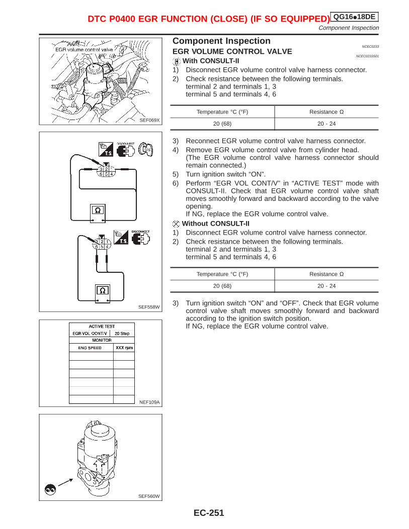
Component InspectionNCEC0233
EGR VOLUME CONTROL VALVENCEC0233S01
With CONSULT-II1) Disconnect EGR volume control valve harness connector.2) Check resistance between the following terminals.
terminal 2 and terminals 1, 3terminal 5 and terminals 4, 6
Temperature °C (°F) Resistance Ω
20 (68) 20 - 24
3) Reconnect EGR volume control valve harness connector.4) Remove EGR volume control valve from cylinder head.
(The EGR volume control valve harness connector shouldremain connected.)
5) Turn ignition switch “ON”.6) Perform “EGR VOL CONT/V” in “ACTIVE TEST” mode with
CONSULT-II. Check that EGR volume control valve shaftmoves smoothly forward and backward according to the valveopening.If NG, replace the EGR volume control valve.
Without CONSULT-II1) Disconnect EGR volume control valve harness connector.2) Check resistance between the following terminals.
terminal 2 and terminals 1, 3terminal 5 and terminals 4, 6
Temperature °C (°F) Resistance Ω
20 (68) 20 - 24
3) Turn ignition switch “ON” and “OFF”. Check that EGR volumecontrol valve shaft moves smoothly forward and backwardaccording to the ignition switch position.If NG, replace the EGR volume control valve.
SEF069X
SEF558W
NEF109A
SEF560W
DTC P0400 EGR FUNCTION (CLOSE) (IF SO EQUIPPED) QG16I18DEComponent Inspection
EC-251
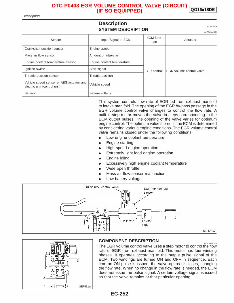
DescriptionNCEC0504
SYSTEM DESCRIPTIONNCEC0504S01
Sensor Input Signal to ECMECM func-
tionActuator
Crankshaft position sensor Engine speed
EGR control EGR volume control valve
Mass air flow sensor Amount of intake air
Engine coolant temperature sensor Engine coolant temperature
Ignition switch Start signal
Throttle position sensor Throttle position
Vehicle speed sensor or ABS actuator andelectric unit (control unit)
Vehicle speed
Battery Battery voltage
This system controls flow rate of EGR led from exhaust manifoldto intake manifold. The opening of the EGR by-pass passage in theEGR volume control valve changes to control the flow rate. Abuilt-in step motor moves the valve in steps corresponding to theECM output pulses. The opening of the valve varies for optimumengine control. The optimum value stored in the ECM is determinedby considering various engine conditions. The EGR volume controlvalve remains closed under the following conditions.I Low engine coolant temperatureI Engine startingI High-speed engine operationI Extremely light load engine operationI Engine idlingI Excessively high engine coolant temperatureI Wide open throttleI Mass air flow sensor malfunctionI Low battery voltage
COMPONENT DESCRIPTIONNCEC0504S02
The EGR volume control valve uses a step motor to control the flowrate of EGR from exhaust manifold. This motor has four windingphases. It operates according to the output pulse signal of theECM. Two windings are turned ON and OFF in sequence. Eachtime an ON pulse is issued, the valve opens or closes, changingthe flow rate. When no change in the flow rate is needed, the ECMdoes not issue the pulse signal. A certain voltage signal is issuedso that the valve remains at that particular opening.
SEF551W
SEF552W
DTC P0403 EGR VOLUME CONTROL VALVE (CIRCUIT)(IF SO EQUIPPED) QG16I18DE
Description
EC-252
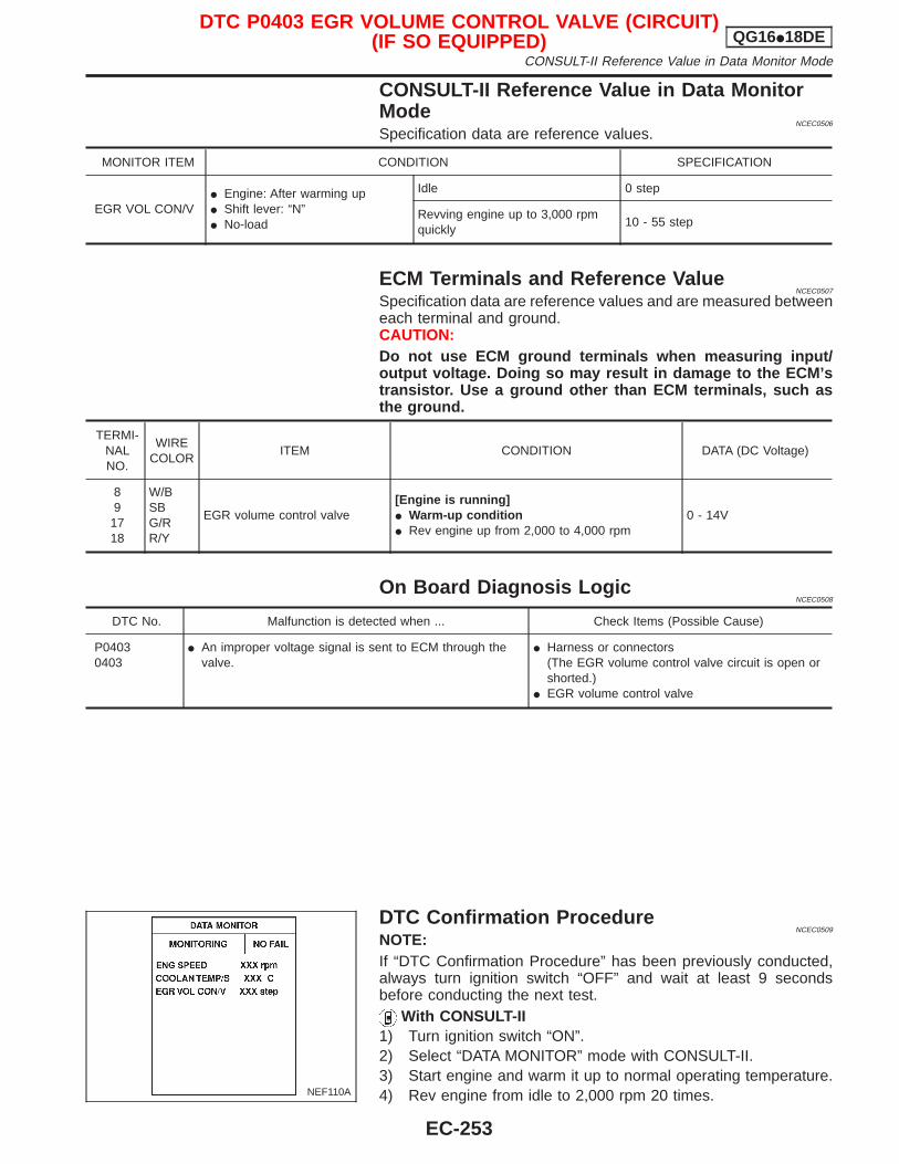
CONSULT-II Reference Value in Data MonitorMode
NCEC0506
Specification data are reference values.
MONITOR ITEM CONDITION SPECIFICATION
EGR VOL CON/VI Engine: After warming upI Shift lever: “N”I No-load
Idle 0 step
Revving engine up to 3,000 rpmquickly
10 - 55 step
ECM Terminals and Reference ValueNCEC0507
Specification data are reference values and are measured betweeneach terminal and ground.CAUTION:Do not use ECM ground terminals when measuring input/output voltage. Doing so may result in damage to the ECM’stransistor. Use a ground other than ECM terminals, such asthe ground.
TERMI-NALNO.
WIRECOLOR
ITEM CONDITION DATA (DC Voltage)
89
1718
W/BSBG/RR/Y
EGR volume control valve[Engine is running]I Warm-up conditionI Rev engine up from 2,000 to 4,000 rpm
0 - 14V
On Board Diagnosis LogicNCEC0508
DTC No. Malfunction is detected when ... Check Items (Possible Cause)
P04030403
I An improper voltage signal is sent to ECM through thevalve.
I Harness or connectors(The EGR volume control valve circuit is open orshorted.)
I EGR volume control valve
DTC Confirmation ProcedureNCEC0509
NOTE:If “DTC Confirmation Procedure” has been previously conducted,always turn ignition switch “OFF” and wait at least 9 secondsbefore conducting the next test.
With CONSULT-II1) Turn ignition switch “ON”.2) Select “DATA MONITOR” mode with CONSULT-II.3) Start engine and warm it up to normal operating temperature.4) Rev engine from idle to 2,000 rpm 20 times.NEF110A
DTC P0403 EGR VOLUME CONTROL VALVE (CIRCUIT)(IF SO EQUIPPED) QG16I18DE
CONSULT-II Reference Value in Data Monitor Mode
EC-253
If 1st trip DTC is detected, go to “Diagnostic Procedure”, EC-QG-256.
With GSTFollow the procedure “With CONSULT-II” above.
DTC P0403 EGR VOLUME CONTROL VALVE (CIRCUIT)(IF SO EQUIPPED) QG16I18DE
DTC Confirmation Procedure (Cont’d)
EC-254
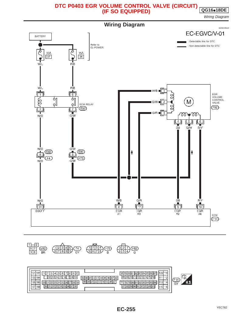
Wiring DiagramNCEC0510
YEC782
: Detectable line for DTC
: Non-detectable line for DTC
ECM
ECM RELAY
EGRVOLUMECONTROLVALVE
Refer toEL-POWER.
BATTERY
DTC P0403 EGR VOLUME CONTROL VALVE (CIRCUIT)(IF SO EQUIPPED) QG16I18DE
Wiring Diagram
EC-255
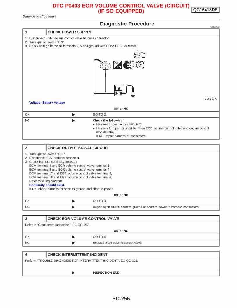
Diagnostic ProcedureNCEC0511
1 CHECK POWER SUPPLY
1. Disconnect EGR volume control valve harness connector.2. Turn ignition switch “ON”.3. Check voltage between terminals 2, 5 and ground with CONSULT-II or tester.
SEF556WVoltage: Battery voltage
OK or NG
OK © GO TO 2.
NG © Check the following.I Harness or connectors E90, F73I Harness for open or short between EGR volume control valve and engine control
module relayIf NG, repair harness or connectors.
2 CHECK OUTPUT SIGNAL CIRCUIT
1. Turn ignition switch “OFF”.2. Disconnect ECM harness connector.3. Check harness continuity between
ECM terminal 8 and EGR volume control valve terminal 1,ECM terminal 9 and EGR volume control valve terminal 4,ECM terminal 17 and EGR volume control valve terminal 3,ECM terminal 18 and EGR volume control valve terminal 6.Refer to wiring diagram.Continuity should exist.If OK, check harness for short to ground and short to power.
OK or NG
OK © GO TO 3.
NG © Repair open circuit, short to ground or short to power in harness connectors.
3 CHECK EGR VOLUME CONTROL VALVE
Refer to “Component Inspection”, EC-QG-257.
OK or NG
OK © GO TO 4.
NG © Replace EGR volume control valve.
4 CHECK INTERMITTENT INCIDENT
Perform “TROUBLE DIAGNOSIS FOR INTERMITTENT INCIDENT”, EC-QG-102.
© INSPECTION END
DTC P0403 EGR VOLUME CONTROL VALVE (CIRCUIT)(IF SO EQUIPPED) QG16I18DE
Diagnostic Procedure
EC-256
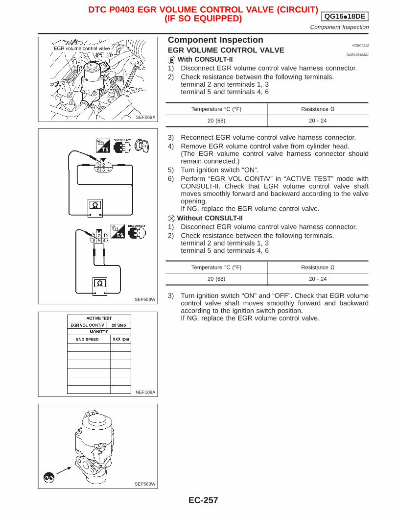
Component InspectionNCEC0512
EGR VOLUME CONTROL VALVENCEC0512S01
With CONSULT-II1) Disconnect EGR volume control valve harness connector.2) Check resistance between the following terminals.
terminal 2 and terminals 1, 3terminal 5 and terminals 4, 6
Temperature °C (°F) Resistance Ω
20 (68) 20 - 24
3) Reconnect EGR volume control valve harness connector.4) Remove EGR volume control valve from cylinder head.
(The EGR volume control valve harness connector shouldremain connected.)
5) Turn ignition switch “ON”.6) Perform “EGR VOL CONT/V” in “ACTIVE TEST” mode with
CONSULT-II. Check that EGR volume control valve shaftmoves smoothly forward and backward according to the valveopening.If NG, replace the EGR volume control valve.
Without CONSULT-II1) Disconnect EGR volume control valve harness connector.2) Check resistance between the following terminals.
terminal 2 and terminals 1, 3terminal 5 and terminals 4, 6
Temperature °C (°F) Resistance Ω
20 (68) 20 - 24
3) Turn ignition switch “ON” and “OFF”. Check that EGR volumecontrol valve shaft moves smoothly forward and backwardaccording to the ignition switch position.If NG, replace the EGR volume control valve.
SEF069X
SEF558W
NEF109A
SEF560W
DTC P0403 EGR VOLUME CONTROL VALVE (CIRCUIT)(IF SO EQUIPPED) QG16I18DE
Component Inspection
EC-257
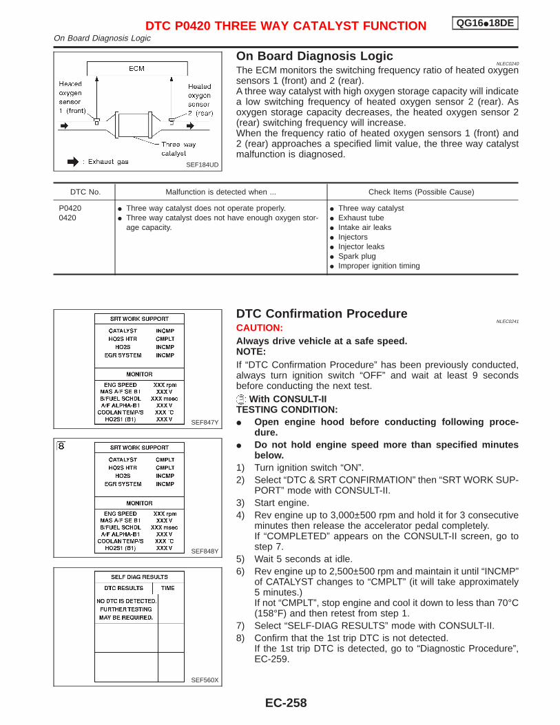
On Board Diagnosis LogicNLEC0240
The ECM monitors the switching frequency ratio of heated oxygensensors 1 (front) and 2 (rear).A three way catalyst with high oxygen storage capacity will indicatea low switching frequency of heated oxygen sensor 2 (rear). Asoxygen storage capacity decreases, the heated oxygen sensor 2(rear) switching frequency will increase.When the frequency ratio of heated oxygen sensors 1 (front) and2 (rear) approaches a specified limit value, the three way catalystmalfunction is diagnosed.
DTC No. Malfunction is detected when ... Check Items (Possible Cause)
P04200420
I Three way catalyst does not operate properly.I Three way catalyst does not have enough oxygen stor-
age capacity.
I Three way catalystI Exhaust tubeI Intake air leaksI InjectorsI Injector leaksI Spark plugI Improper ignition timing
DTC Confirmation ProcedureNLEC0241
CAUTION:Always drive vehicle at a safe speed.NOTE:If “DTC Confirmation Procedure” has been previously conducted,always turn ignition switch “OFF” and wait at least 9 secondsbefore conducting the next test.
With CONSULT-IITESTING CONDITION:I Open engine hood before conducting following proce-
dure.I Do not hold engine speed more than specified minutes
below.1) Turn ignition switch “ON”.2) Select “DTC & SRT CONFIRMATION” then “SRT WORK SUP-
PORT” mode with CONSULT-II.3) Start engine.4) Rev engine up to 3,000±500 rpm and hold it for 3 consecutive
minutes then release the accelerator pedal completely.If “COMPLETED” appears on the CONSULT-II screen, go tostep 7.
5) Wait 5 seconds at idle.6) Rev engine up to 2,500±500 rpm and maintain it until “INCMP”
of CATALYST changes to “CMPLT” (it will take approximately5 minutes.)If not “CMPLT”, stop engine and cool it down to less than 70°C(158°F) and then retest from step 1.
7) Select “SELF-DIAG RESULTS” mode with CONSULT-II.8) Confirm that the 1st trip DTC is not detected.
If the 1st trip DTC is detected, go to “Diagnostic Procedure”,EC-259.
SEF184UD
SEF847Y
SEF848Y
SEF560X
DTC P0420 THREE WAY CATALYST FUNCTION QG16I18DEOn Board Diagnosis Logic
EC-258
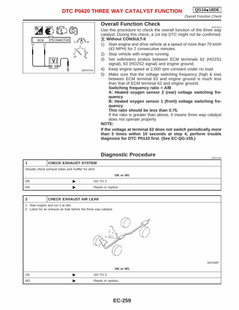
Overall Function CheckNCEC0242
Use this procedure to check the overall function of the three waycatalyst. During this check, a 1st trip DTC might not be confirmed.
Without CONSULT-II1) Start engine and drive vehicle at a speed of more than 70 km/h
(43 MPH) for 2 consecutive minutes.2) Stop vehicle with engine running.3) Set voltmeters probes between ECM terminals 62 (HO2S1
signal), 63 (HO2S2 signal) and engine ground.4) Keep engine speed at 2,000 rpm constant under no load.5) Make sure that the voltage switching frequency (high & low)
between ECM terminal 63 and engine ground is much lessthan that of ECM terminal 62 and engine ground.Switching frequency ratio = A/BA: Heated oxygen sensor 2 (rear) voltage switching fre-quencyB: Heated oxygen sensor 1 (front) voltage switching fre-quencyThis ratio should be less than 0.75.If the ratio is greater than above, it means three way catalystdoes not operate properly.
NOTE:If the voltage at terminal 62 does not switch periodically morethan 5 times within 10 seconds at step 4, perform troublediagnosis for DTC P0133 first. (See EC-QG-155.)
Diagnostic ProcedureNCEC0243
1 CHECK EXHAUST SYSTEM
Visually check exhaust tubes and muffler for dent.
OK or NG
OK © GO TO 2.
NG © Repair or replace.
2 CHECK EXHAUST AIR LEAK
1. Start engine and run it at idle.2. Listen for an exhaust air leak before the three way catalyst.
SEF099P
OK or NG
OK © GO TO 3.
NG © Repair or replace.
SEF074X
DTC P0420 THREE WAY CATALYST FUNCTION QG16I18DEOverall Function Check
EC-259
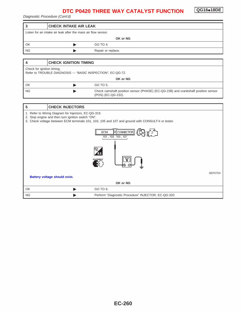
3 CHECK INTAKE AIR LEAK
Listen for an intake air leak after the mass air flow sensor.
OK or NG
OK © GO TO 4.
NG © Repair or replace.
4 CHECK IGNITION TIMING
Check for ignition timing.Refer to TROUBLE DIAGNOSIS — “BASIC INSPECTION”, EC-QG-72.
OK or NG
OK © GO TO 5.
NG © Check camshaft position sensor (PHASE) (EC-QG-238) and crankshaft position sensor(POS) (EC-QG-232).
5 CHECK INJECTORS
1. Refer to Wiring Diagram for Injectors, EC-QG-319.2. Stop engine and then turn ignition switch “ON”.3. Check voltage between ECM terminals 101, 103, 105 and 107 and ground with CONSULT-II or tester.
SEF075XBattery voltage should exist.
OK or NG
OK © GO TO 6.
NG © Perform “Diagnostic Procedure” INJECTOR, EC-QG-320.
DTC P0420 THREE WAY CATALYST FUNCTION QG16I18DEDiagnostic Procedure (Cont’d)
EC-260
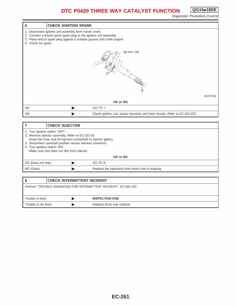
6 CHECK IGNITION SPARK
1. Disconnect ignition coil assembly from rocker cover.2. Connect a known good spark plug to the ignition coil assembly.3. Place end of spark plug against a suitable ground and crank engine.4. Check for spark.
SEF575Q
OK or NG
OK © GO TO 7.
NG © Check ignition coil, power transistor and their circuits. Refer to EC-QG-323.
7 CHECK INJECTOR
1. Turn ignition switch “OFF”.2. Remove injector assembly. Refer to EC-QG-30.
Keep fuel hose and all injectors connected to injector gallery.3. Disconnect camshaft position sensor harness connector.4. Turn ignition switch “ON”.
Make sure fuel does not drip from injector.
OK or NG
OK (Does not drip) © GO TO 8.
NG (Drips) © Replace the injector(s) from which fuel is dripping.
8 CHECK INTERMITTENT INCIDENT
Perform “TROUBLE DIAGNOSIS FOR INTERMITTENT INCIDENT”, EC-QG-102.
Trouble is fixed © INSPECTION END
Trouble is not fixed © Replace three way catalyst.
DTC P0420 THREE WAY CATALYST FUNCTION QG16I18DEDiagnostic Procedure (Cont’d)
EC-261
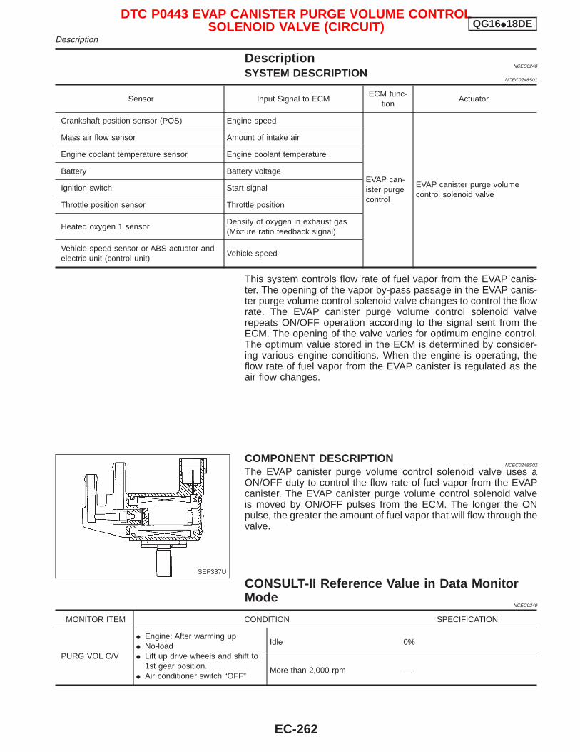
DescriptionNCEC0248
SYSTEM DESCRIPTIONNCEC0248S01
Sensor Input Signal to ECMECM func-
tionActuator
Crankshaft position sensor (POS) Engine speed
EVAP can-ister purgecontrol
EVAP canister purge volumecontrol solenoid valve
Mass air flow sensor Amount of intake air
Engine coolant temperature sensor Engine coolant temperature
Battery Battery voltage
Ignition switch Start signal
Throttle position sensor Throttle position
Heated oxygen 1 sensorDensity of oxygen in exhaust gas(Mixture ratio feedback signal)
Vehicle speed sensor or ABS actuator andelectric unit (control unit)
Vehicle speed
This system controls flow rate of fuel vapor from the EVAP canis-ter. The opening of the vapor by-pass passage in the EVAP canis-ter purge volume control solenoid valve changes to control the flowrate. The EVAP canister purge volume control solenoid valverepeats ON/OFF operation according to the signal sent from theECM. The opening of the valve varies for optimum engine control.The optimum value stored in the ECM is determined by consider-ing various engine conditions. When the engine is operating, theflow rate of fuel vapor from the EVAP canister is regulated as theair flow changes.
COMPONENT DESCRIPTIONNCEC0248S02
The EVAP canister purge volume control solenoid valve uses aON/OFF duty to control the flow rate of fuel vapor from the EVAPcanister. The EVAP canister purge volume control solenoid valveis moved by ON/OFF pulses from the ECM. The longer the ONpulse, the greater the amount of fuel vapor that will flow through thevalve.
CONSULT-II Reference Value in Data MonitorMode
NCEC0249
MONITOR ITEM CONDITION SPECIFICATION
PURG VOL C/V
I Engine: After warming upI No-loadI Lift up drive wheels and shift to
1st gear position.I Air conditioner switch “OFF”
Idle 0%
More than 2,000 rpm —
SEF337U
DTC P0443 EVAP CANISTER PURGE VOLUME CONTROLSOLENOID VALVE (CIRCUIT) QG16I18DE
Description
EC-262
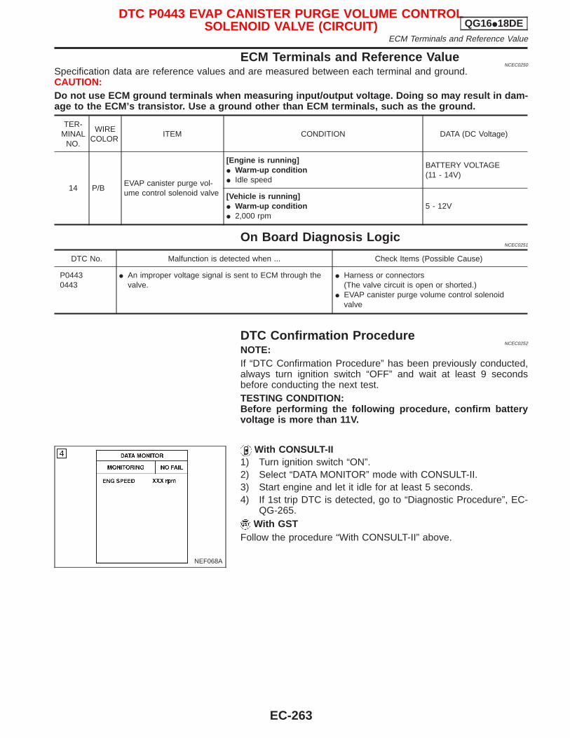
ECM Terminals and Reference ValueNCEC0250
Specification data are reference values and are measured between each terminal and ground.CAUTION:Do not use ECM ground terminals when measuring input/output voltage. Doing so may result in dam-age to the ECM’s transistor. Use a ground other than ECM terminals, such as the ground.
TER-MINAL
NO.
WIRECOLOR
ITEM CONDITION DATA (DC Voltage)
14 P/BEVAP canister purge vol-ume control solenoid valve
[Engine is running]I Warm-up conditionI Idle speed
BATTERY VOLTAGE(11 - 14V)
[Vehicle is running]I Warm-up conditionI 2,000 rpm
5 - 12V
On Board Diagnosis LogicNCEC0251
DTC No. Malfunction is detected when ... Check Items (Possible Cause)
P04430443
I An improper voltage signal is sent to ECM through thevalve.
I Harness or connectors(The valve circuit is open or shorted.)
I EVAP canister purge volume control solenoidvalve
DTC Confirmation ProcedureNCEC0252
NOTE:If “DTC Confirmation Procedure” has been previously conducted,always turn ignition switch “OFF” and wait at least 9 secondsbefore conducting the next test.TESTING CONDITION:Before performing the following procedure, confirm batteryvoltage is more than 11V.
With CONSULT-II1) Turn ignition switch “ON”.2) Select “DATA MONITOR” mode with CONSULT-II.3) Start engine and let it idle for at least 5 seconds.4) If 1st trip DTC is detected, go to “Diagnostic Procedure”, EC-
QG-265.With GST
Follow the procedure “With CONSULT-II” above.
NEF068A
DTC P0443 EVAP CANISTER PURGE VOLUME CONTROLSOLENOID VALVE (CIRCUIT) QG16I18DE
ECM Terminals and Reference Value
EC-263
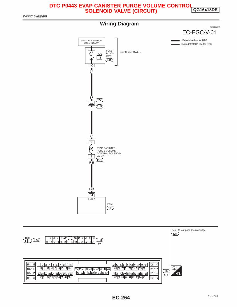
Wiring DiagramNCEC0253
YEC783
: Detectable line for DTC
: Non-detectable line for DTC
ECM
EVAP CANISTERPURGE VOLUMECONTROL SOLENOIDVALVE
FUSEBLOCK(J/B)
Refer to EL-POWER.
IGNITION SWITCHON or START
Refer to last page (Foldout page)
DTC P0443 EVAP CANISTER PURGE VOLUME CONTROLSOLENOID VALVE (CIRCUIT) QG16I18DE
Wiring Diagram
EC-264
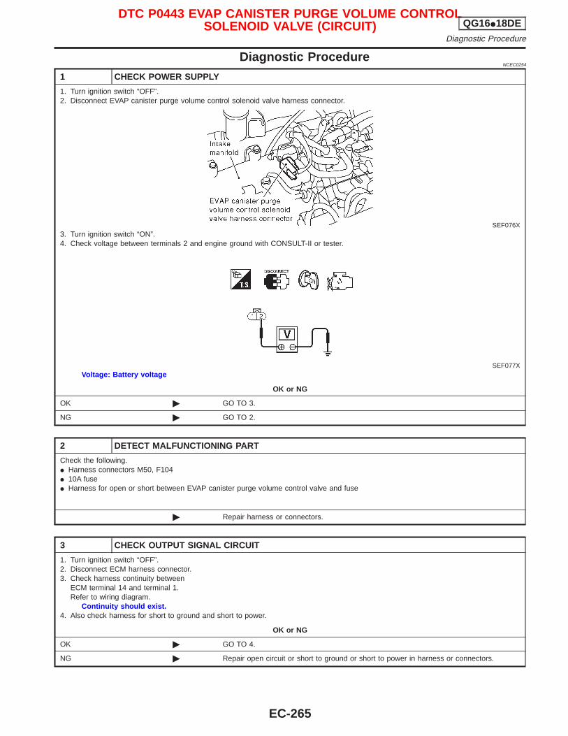
Diagnostic ProcedureNCEC0254
1 CHECK POWER SUPPLY
1. Turn ignition switch “OFF”.2. Disconnect EVAP canister purge volume control solenoid valve harness connector.
SEF076X3. Turn ignition switch “ON”.4. Check voltage between terminals 2 and engine ground with CONSULT-II or tester.
SEF077XVoltage: Battery voltage
OK or NG
OK © GO TO 3.
NG © GO TO 2.
2 DETECT MALFUNCTIONING PART
Check the following.I Harness connectors M50, F104I 10A fuseI Harness for open or short between EVAP canister purge volume control valve and fuse
© Repair harness or connectors.
3 CHECK OUTPUT SIGNAL CIRCUIT
1. Turn ignition switch “OFF”.2. Disconnect ECM harness connector.3. Check harness continuity between
ECM terminal 14 and terminal 1.Refer to wiring diagram.
Continuity should exist.4. Also check harness for short to ground and short to power.
OK or NG
OK © GO TO 4.
NG © Repair open circuit or short to ground or short to power in harness or connectors.
DTC P0443 EVAP CANISTER PURGE VOLUME CONTROLSOLENOID VALVE (CIRCUIT) QG16I18DE
Diagnostic Procedure
EC-265
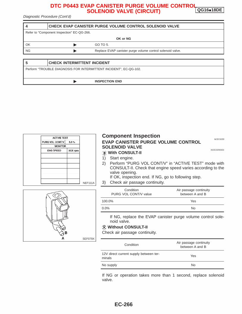
4 CHECK EVAP CANISTER PURGE VOLUME CONTROL SOLENOID VALVE
Refer to “Component Inspection” EC-QG-266.
OK or NG
OK © GO TO 5.
NG © Replace EVAP canister purge volume control solenoid valve.
5 CHECK INTERMITTENT INCIDENT
Perform “TROUBLE DIAGNOSIS FOR INTERMITTENT INCIDENT”, EC-QG-102.
© INSPECTION END
Component InspectionNCEC0255
EVAP CANISTER PURGE VOLUME CONTROLSOLENOID VALVE
NCEC0255S01
With CONSULT-II1) Start engine.2) Perform “PURG VOL CONT/V” in “ACTIVE TEST” mode with
CONSULT-II. Check that engine speed varies according to thevalve opening.If OK, inspection end. If NG, go to following step.
3) Check air passage continuity.
ConditionPURG VOL CONT/V value
Air passage continuitybetween A and B
100.0% Yes
0.0% No
If NG, replace the EVAP canister purge volume control sole-noid valve.
Without CONSULT-IICheck air passage continuity.
ConditionAir passage continuity
between A and B
12V direct current supply between ter-minals
Yes
No supply No
If NG or operation takes more than 1 second, replace solenoidvalve.
NEF111A
SEF079X
DTC P0443 EVAP CANISTER PURGE VOLUME CONTROLSOLENOID VALVE (CIRCUIT) QG16I18DE
Diagnostic Procedure (Cont’d)
EC-266
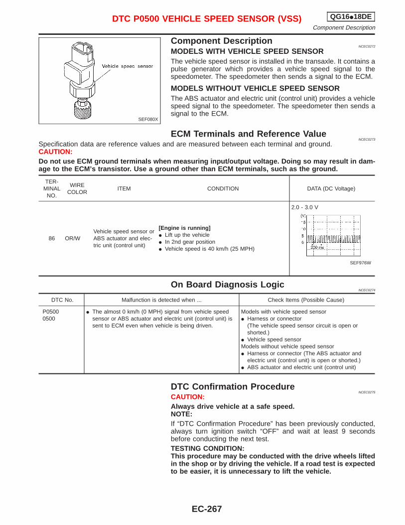
Component DescriptionNCEC0272
MODELS WITH VEHICLE SPEED SENSORThe vehicle speed sensor is installed in the transaxle. It contains apulse generator which provides a vehicle speed signal to thespeedometer. The speedometer then sends a signal to the ECM.
MODELS WITHOUT VEHICLE SPEED SENSORThe ABS actuator and electric unit (control unit) provides a vehiclespeed signal to the speedometer. The speedometer then sends asignal to the ECM.
ECM Terminals and Reference ValueNCEC0273
Specification data are reference values and are measured between each terminal and ground.CAUTION:Do not use ECM ground terminals when measuring input/output voltage. Doing so may result in dam-age to the ECM’s transistor. Use a ground other than ECM terminals, such as the ground.
TER-MINAL
NO.
WIRECOLOR
ITEM CONDITION DATA (DC Voltage)
86 OR/WVehicle speed sensor orABS actuator and elec-tric unit (control unit)
[Engine is running]I Lift up the vehicleI In 2nd gear positionI Vehicle speed is 40 km/h (25 MPH)
2.0 - 3.0 V
SEF976W
On Board Diagnosis LogicNCEC0274
DTC No. Malfunction is detected when ... Check Items (Possible Cause)
P05000500
I The almost 0 km/h (0 MPH) signal from vehicle speedsensor or ABS actuator and electric unit (control unit) issent to ECM even when vehicle is being driven.
Models with vehicle speed sensorI Harness or connector
(The vehicle speed sensor circuit is open orshorted.)
I Vehicle speed sensorModels without vehicle speed sensorI Harness or connector (The ABS actuator and
electric unit (control unit) is open or shorted.)I ABS actuator and electric unit (control unit)
DTC Confirmation ProcedureNCEC0275
CAUTION:Always drive vehicle at a safe speed.NOTE:If “DTC Confirmation Procedure” has been previously conducted,always turn ignition switch “OFF” and wait at least 9 secondsbefore conducting the next test.TESTING CONDITION:This procedure may be conducted with the drive wheels liftedin the shop or by driving the vehicle. If a road test is expectedto be easier, it is unnecessary to lift the vehicle.
SEF080X
DTC P0500 VEHICLE SPEED SENSOR (VSS) QG16I18DEComponent Description
EC-267
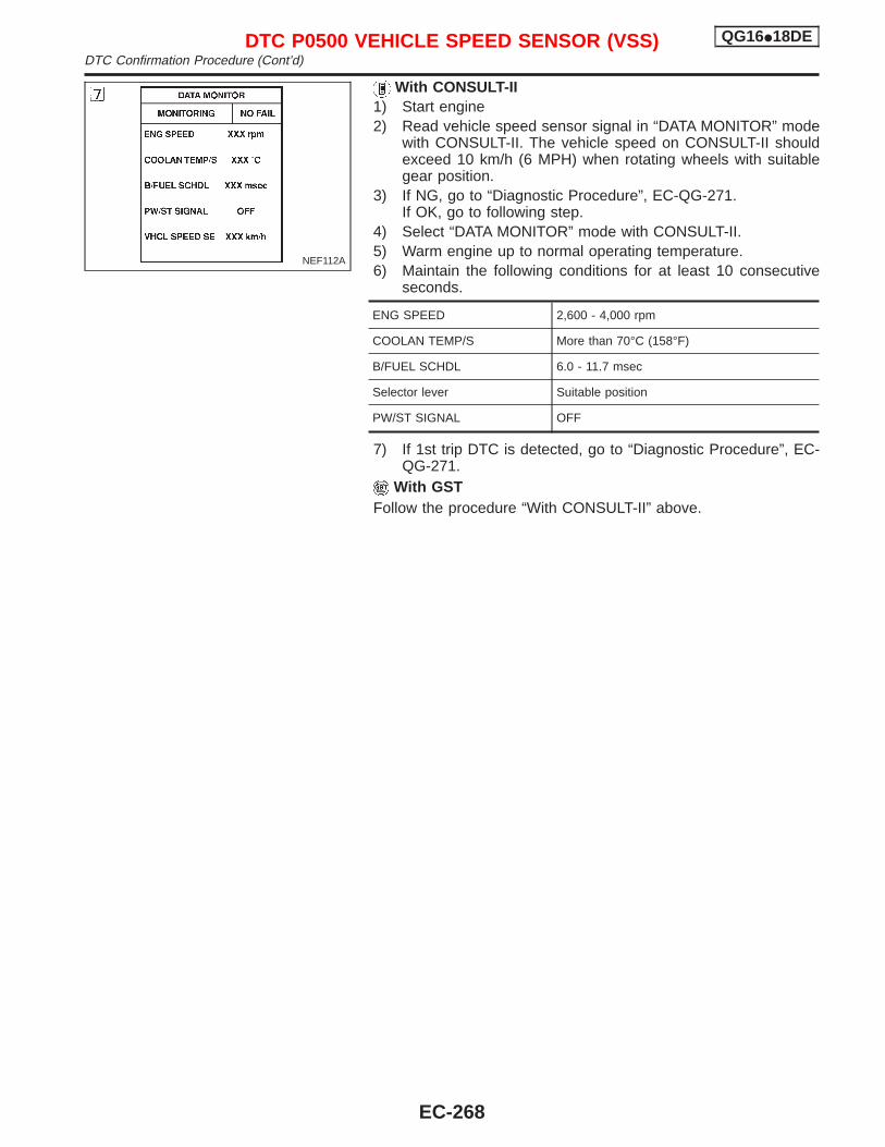
With CONSULT-II1) Start engine2) Read vehicle speed sensor signal in “DATA MONITOR” mode
with CONSULT-II. The vehicle speed on CONSULT-II shouldexceed 10 km/h (6 MPH) when rotating wheels with suitablegear position.
3) If NG, go to “Diagnostic Procedure”, EC-QG-271.If OK, go to following step.
4) Select “DATA MONITOR” mode with CONSULT-II.5) Warm engine up to normal operating temperature.6) Maintain the following conditions for at least 10 consecutive
seconds.
ENG SPEED 2,600 - 4,000 rpm
COOLAN TEMP/S More than 70°C (158°F)
B/FUEL SCHDL 6.0 - 11.7 msec
Selector lever Suitable position
PW/ST SIGNAL OFF
7) If 1st trip DTC is detected, go to “Diagnostic Procedure”, EC-QG-271.
With GSTFollow the procedure “With CONSULT-II” above.
NEF112A
DTC P0500 VEHICLE SPEED SENSOR (VSS) QG16I18DEDTC Confirmation Procedure (Cont’d)
EC-268
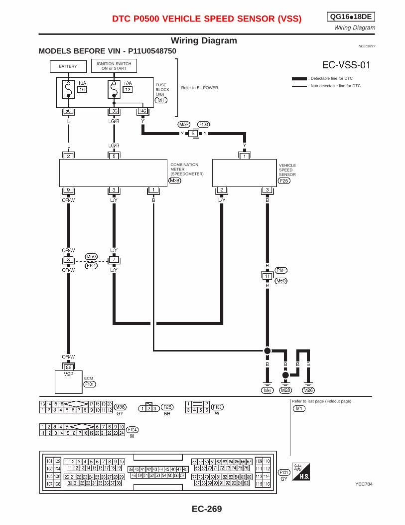
Wiring DiagramNCEC0277
MODELS BEFORE VIN - P11U0548750
YEC784
IGNITION SWITCHON or START
Refer to EL-POWER.
: Detectable line for DTC
: Non-detectable line for DTCFUSEBLOCK(J/B)
COMBINATIONMETER(SPEEDOMETER)
ECM
Refer to last page (Foldout page)
VEHICLESPEEDSENSOR
BATTERY
DTC P0500 VEHICLE SPEED SENSOR (VSS) QG16I18DEWiring Diagram
EC-269
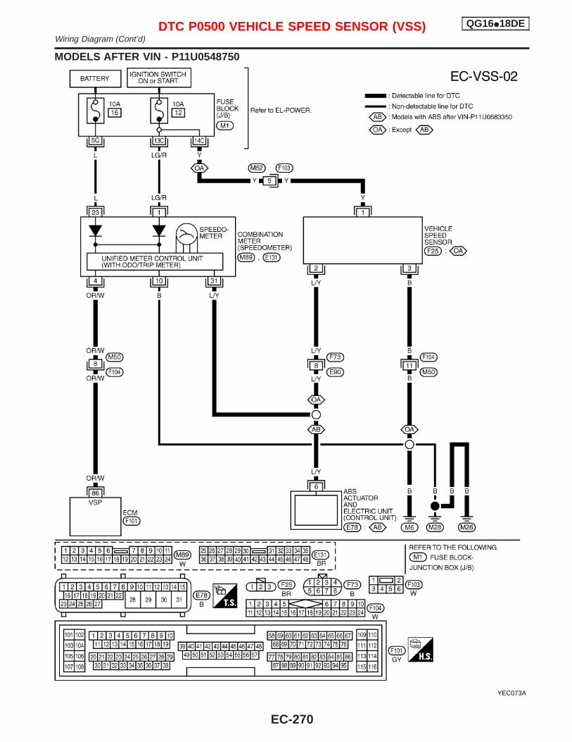
MODELS AFTER VIN - P11U0548750
YEC073A
DTC P0500 VEHICLE SPEED SENSOR (VSS) QG16I18DEWiring Diagram (Cont’d)
EC-270
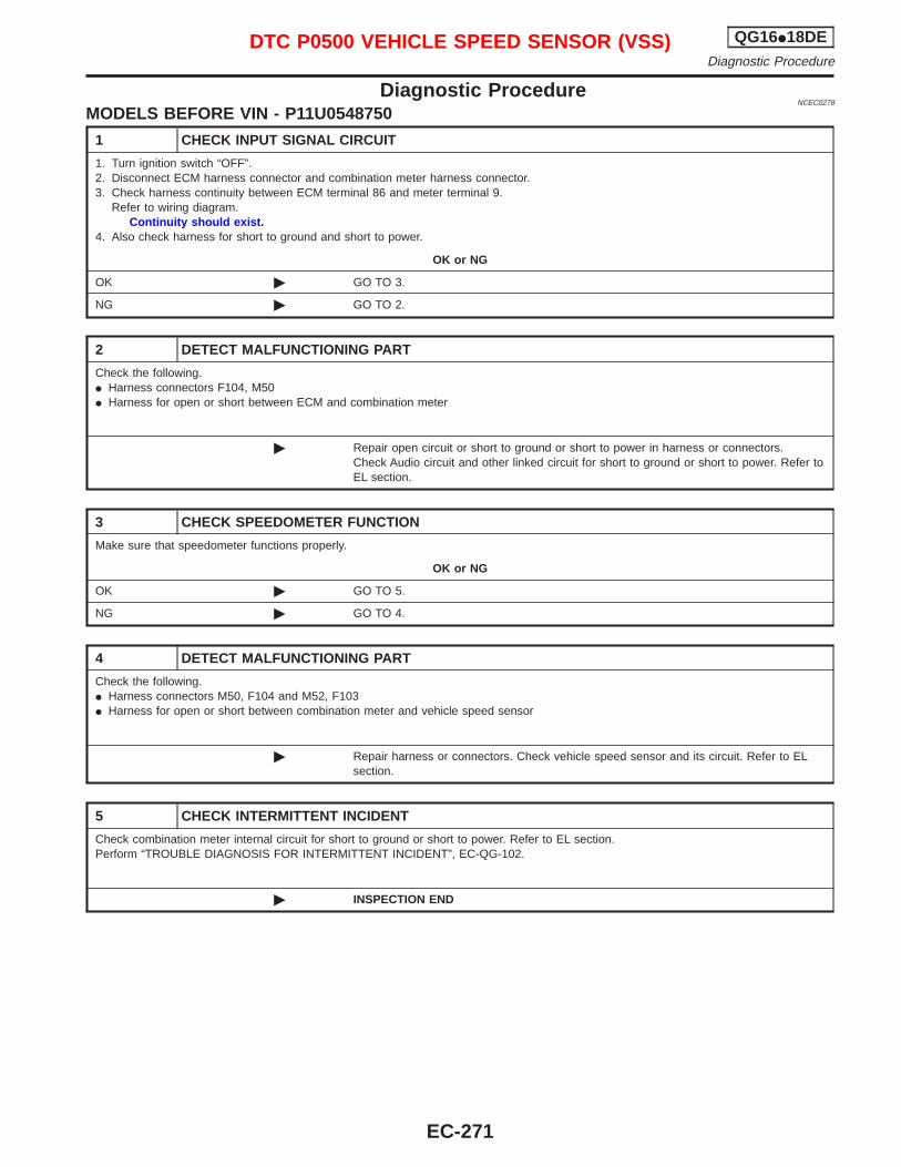
Diagnostic ProcedureNCEC0278
MODELS BEFORE VIN - P11U0548750
1 CHECK INPUT SIGNAL CIRCUIT
1. Turn ignition switch “OFF”.2. Disconnect ECM harness connector and combination meter harness connector.3. Check harness continuity between ECM terminal 86 and meter terminal 9.
Refer to wiring diagram.Continuity should exist.
4. Also check harness for short to ground and short to power.
OK or NG
OK © GO TO 3.
NG © GO TO 2.
2 DETECT MALFUNCTIONING PART
Check the following.I Harness connectors F104, M50I Harness for open or short between ECM and combination meter
© Repair open circuit or short to ground or short to power in harness or connectors.Check Audio circuit and other linked circuit for short to ground or short to power. Refer toEL section.
3 CHECK SPEEDOMETER FUNCTION
Make sure that speedometer functions properly.
OK or NG
OK © GO TO 5.
NG © GO TO 4.
4 DETECT MALFUNCTIONING PART
Check the following.I Harness connectors M50, F104 and M52, F103I Harness for open or short between combination meter and vehicle speed sensor
© Repair harness or connectors. Check vehicle speed sensor and its circuit. Refer to ELsection.
5 CHECK INTERMITTENT INCIDENT
Check combination meter internal circuit for short to ground or short to power. Refer to EL section.Perform “TROUBLE DIAGNOSIS FOR INTERMITTENT INCIDENT”, EC-QG-102.
© INSPECTION END
DTC P0500 VEHICLE SPEED SENSOR (VSS) QG16I18DEDiagnostic Procedure
EC-271
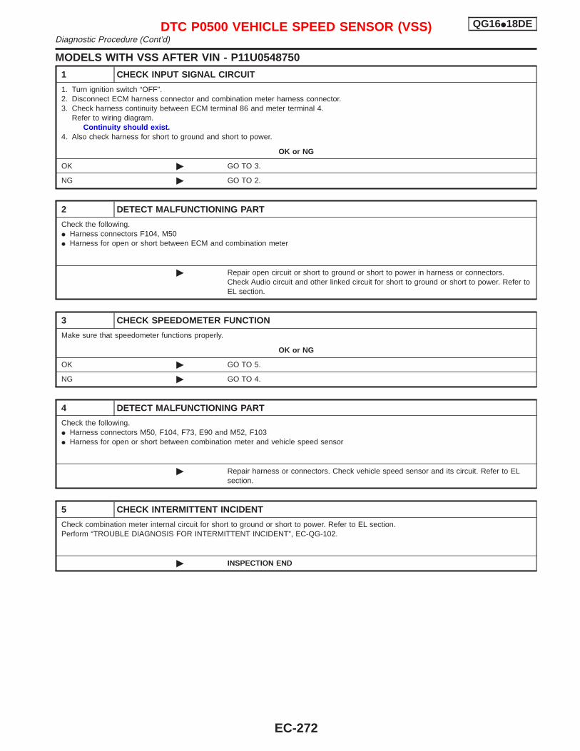
MODELS WITH VSS AFTER VIN - P11U0548750
1 CHECK INPUT SIGNAL CIRCUIT
1. Turn ignition switch “OFF”.2. Disconnect ECM harness connector and combination meter harness connector.3. Check harness continuity between ECM terminal 86 and meter terminal 4.
Refer to wiring diagram.Continuity should exist.
4. Also check harness for short to ground and short to power.
OK or NG
OK © GO TO 3.
NG © GO TO 2.
2 DETECT MALFUNCTIONING PART
Check the following.I Harness connectors F104, M50I Harness for open or short between ECM and combination meter
© Repair open circuit or short to ground or short to power in harness or connectors.Check Audio circuit and other linked circuit for short to ground or short to power. Refer toEL section.
3 CHECK SPEEDOMETER FUNCTION
Make sure that speedometer functions properly.
OK or NG
OK © GO TO 5.
NG © GO TO 4.
4 DETECT MALFUNCTIONING PART
Check the following.I Harness connectors M50, F104, F73, E90 and M52, F103I Harness for open or short between combination meter and vehicle speed sensor
© Repair harness or connectors. Check vehicle speed sensor and its circuit. Refer to ELsection.
5 CHECK INTERMITTENT INCIDENT
Check combination meter internal circuit for short to ground or short to power. Refer to EL section.Perform “TROUBLE DIAGNOSIS FOR INTERMITTENT INCIDENT”, EC-QG-102.
© INSPECTION END
DTC P0500 VEHICLE SPEED SENSOR (VSS) QG16I18DEDiagnostic Procedure (Cont’d)
EC-272
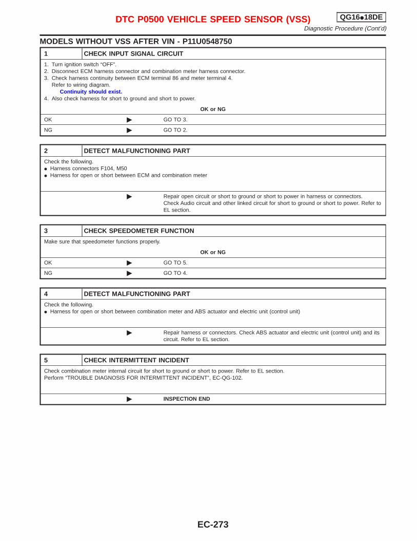
MODELS WITHOUT VSS AFTER VIN - P11U0548750
1 CHECK INPUT SIGNAL CIRCUIT
1. Turn ignition switch “OFF”.2. Disconnect ECM harness connector and combination meter harness connector.3. Check harness continuity between ECM terminal 86 and meter terminal 4.
Refer to wiring diagram.Continuity should exist.
4. Also check harness for short to ground and short to power.
OK or NG
OK © GO TO 3.
NG © GO TO 2.
2 DETECT MALFUNCTIONING PART
Check the following.I Harness connectors F104, M50I Harness for open or short between ECM and combination meter
© Repair open circuit or short to ground or short to power in harness or connectors.Check Audio circuit and other linked circuit for short to ground or short to power. Refer toEL section.
3 CHECK SPEEDOMETER FUNCTION
Make sure that speedometer functions properly.
OK or NG
OK © GO TO 5.
NG © GO TO 4.
4 DETECT MALFUNCTIONING PART
Check the following.I Harness for open or short between combination meter and ABS actuator and electric unit (control unit)
© Repair harness or connectors. Check ABS actuator and electric unit (control unit) and itscircuit. Refer to EL section.
5 CHECK INTERMITTENT INCIDENT
Check combination meter internal circuit for short to ground or short to power. Refer to EL section.Perform “TROUBLE DIAGNOSIS FOR INTERMITTENT INCIDENT”, EC-QG-102.
© INSPECTION END
DTC P0500 VEHICLE SPEED SENSOR (VSS) QG16I18DEDiagnostic Procedure (Cont’d)
EC-273
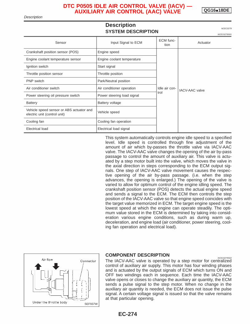
DescriptionNCEC0279
SYSTEM DESCRIPTIONNCEC0279S01
Sensor Input Signal to ECMECM func-
tionActuator
Crankshaft position sensor (POS) Engine speed
Idle air con-trol
IACV-AAC valve
Engine coolant temperature sensor Engine coolant temperature
Ignition switch Start signal
Throttle position sensor Throttle position
PNP switch Park/Neutral position
Air conditioner switch Air conditioner operation
Power steering oil pressure switch Power steering load signal
Battery Battery voltage
Vehicle speed sensor or ABS actuator andelectric unit (control unit)
Vehicle speed
Cooling fan Cooling fan operation
Electrical load Electrical load signal
This system automatically controls engine idle speed to a specifiedlevel. Idle speed is controlled through fine adjustment of theamount of air which by-passes the throttle valve via IACV-AACvalve. The IACV-AAC valve changes the opening of the air by-passpassage to control the amount of auxiliary air. This valve is actu-ated by a step motor built into the valve, which moves the valve inthe axial direction in steps corresponding to the ECM output sig-nals. One step of IACV-AAC valve movement causes the respec-tive opening of the air by-pass passage. (i.e. when the stepadvances, the opening is enlarged.) The opening of the valve isvaried to allow for optimum control of the engine idling speed. Thecrankshaft position sensor (POS) detects the actual engine speedand sends a signal to the ECM. The ECM then controls the stepposition of the IACV-AAC valve so that engine speed coincides withthe target value memorized in ECM. The target engine speed is thelowest speed at which the engine can operate steadily. The opti-mum value stored in the ECM is determined by taking into consid-eration various engine conditions, such as during warm up,deceleration, and engine load (air conditioner, power steering, cool-ing fan operation and electrical load).
COMPONENT DESCRIPTIONNCEC0279S02
The IACV-AAC valve is operated by a step motor for centralizedcontrol of auxiliary air supply. This motor has four winding phasesand is actuated by the output signals of ECM which turns ON andOFF two windings each in sequence. Each time the IACV-AACvalve opens or closes to change the auxiliary air quantity, the ECMsends a pulse signal to the step motor. When no change in theauxiliary air quantity is needed, the ECM does not issue the pulsesignal. A certain voltage signal is issued so that the valve remainsat that particular opening.
SEF937W
DTC P0505 IDLE AIR CONTROL VALVE (IACV) —AUXILIARY AIR CONTROL (AAC) VALVE QG16I18DE
Description
EC-274
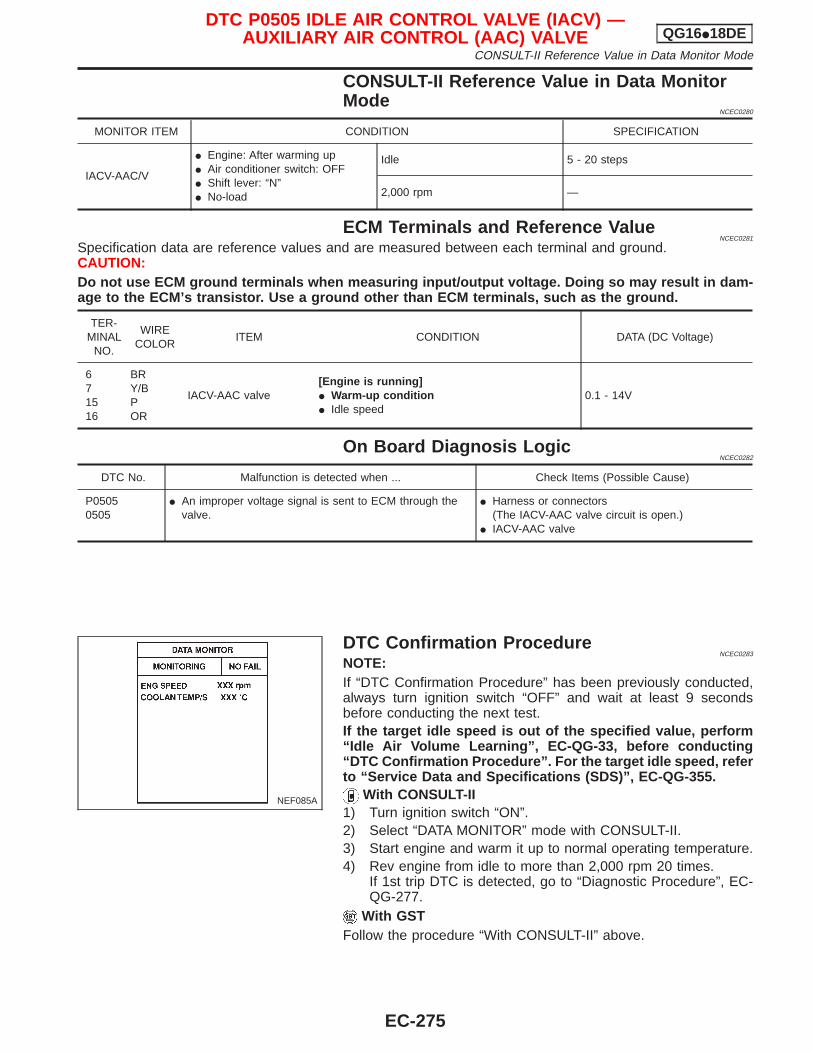
CONSULT-II Reference Value in Data MonitorMode
NCEC0280
MONITOR ITEM CONDITION SPECIFICATION
IACV-AAC/V
I Engine: After warming upI Air conditioner switch: OFFI Shift lever: “N”I No-load
Idle 5 - 20 steps
2,000 rpm —
ECM Terminals and Reference ValueNCEC0281
Specification data are reference values and are measured between each terminal and ground.CAUTION:Do not use ECM ground terminals when measuring input/output voltage. Doing so may result in dam-age to the ECM’s transistor. Use a ground other than ECM terminals, such as the ground.
TER-MINAL
NO.
WIRECOLOR
ITEM CONDITION DATA (DC Voltage)
671516
BRY/BPOR
IACV-AAC valve[Engine is running]I Warm-up conditionI Idle speed
0.1 - 14V
On Board Diagnosis LogicNCEC0282
DTC No. Malfunction is detected when ... Check Items (Possible Cause)
P05050505
I An improper voltage signal is sent to ECM through thevalve.
I Harness or connectors(The IACV-AAC valve circuit is open.)
I IACV-AAC valve
DTC Confirmation ProcedureNCEC0283
NOTE:If “DTC Confirmation Procedure” has been previously conducted,always turn ignition switch “OFF” and wait at least 9 secondsbefore conducting the next test.If the target idle speed is out of the specified value, perform“Idle Air Volume Learning”, EC-QG-33, before conducting“DTC Confirmation Procedure”. For the target idle speed, referto “Service Data and Specifications (SDS)”, EC-QG-355.
With CONSULT-II1) Turn ignition switch “ON”.2) Select “DATA MONITOR” mode with CONSULT-II.3) Start engine and warm it up to normal operating temperature.4) Rev engine from idle to more than 2,000 rpm 20 times.
If 1st trip DTC is detected, go to “Diagnostic Procedure”, EC-QG-277.
With GSTFollow the procedure “With CONSULT-II” above.
NEF085A
DTC P0505 IDLE AIR CONTROL VALVE (IACV) —AUXILIARY AIR CONTROL (AAC) VALVE QG16I18DE
CONSULT-II Reference Value in Data Monitor Mode
EC-275
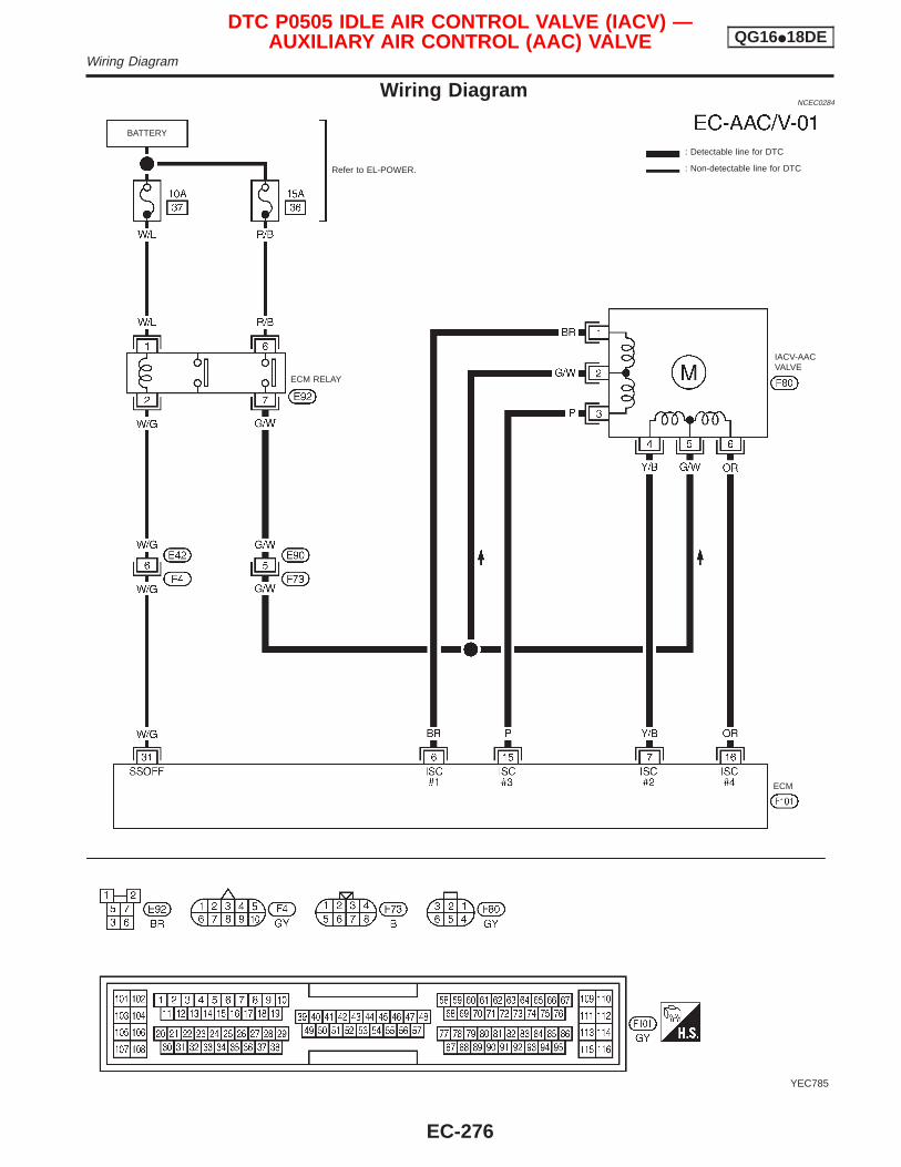
Wiring DiagramNCEC0284
YEC785
: Detectable line for DTC
: Non-detectable line for DTC
ECM
ECM RELAY
Refer to EL-POWER.
BATTERY
IACV-AACVALVE
DTC P0505 IDLE AIR CONTROL VALVE (IACV) —AUXILIARY AIR CONTROL (AAC) VALVE QG16I18DE
Wiring Diagram
EC-276
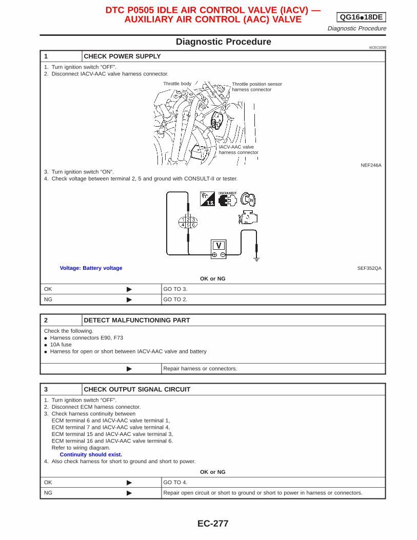
Diagnostic ProcedureNCEC0285
1 CHECK POWER SUPPLY
1. Turn ignition switch “OFF”.2. Disconnect IACV-AAC valve harness connector.
NEF246A3. Turn ignition switch “ON”.4. Check voltage between terminal 2, 5 and ground with CONSULT-II or tester.
SEF352QAVoltage: Battery voltage
OK or NG
OK © GO TO 3.
NG © GO TO 2.
2 DETECT MALFUNCTIONING PART
Check the following.I Harness connectors E90, F73I 10A fuseI Harness for open or short between IACV-AAC valve and battery
© Repair harness or connectors.
3 CHECK OUTPUT SIGNAL CIRCUIT
1. Turn ignition switch “OFF”.2. Disconnect ECM harness connector.3. Check harness continuity between
ECM terminal 6 and IACV-AAC valve terminal 1,ECM terminal 7 and IACV-AAC valve terminal 4,ECM terminal 15 and IACV-AAC valve terminal 3,ECM terminal 16 and IACV-AAC valve terminal 6.Refer to wiring diagram.
Continuity should exist.4. Also check harness for short to ground and short to power.
OK or NG
OK © GO TO 4.
NG © Repair open circuit or short to ground or short to power in harness or connectors.
Throttle body Throttle position sensorharness connector
IACV-AAC valveharness connector
DTC P0505 IDLE AIR CONTROL VALVE (IACV) —AUXILIARY AIR CONTROL (AAC) VALVE QG16I18DE
Diagnostic Procedure
EC-277
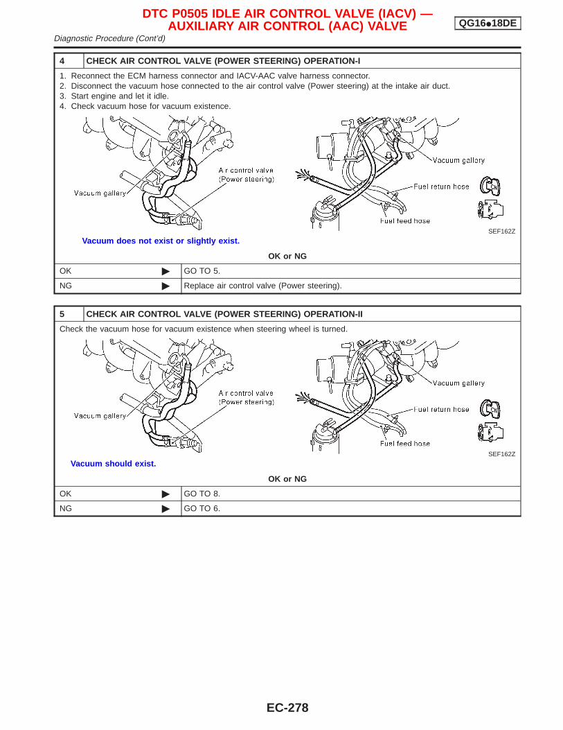
4 CHECK AIR CONTROL VALVE (POWER STEERING) OPERATION-I
1. Reconnect the ECM harness connector and IACV-AAC valve harness connector.2. Disconnect the vacuum hose connected to the air control valve (Power steering) at the intake air duct.3. Start engine and let it idle.4. Check vacuum hose for vacuum existence.
SEF162Z
Vacuum does not exist or slightly exist.
OK or NG
OK © GO TO 5.
NG © Replace air control valve (Power steering).
5 CHECK AIR CONTROL VALVE (POWER STEERING) OPERATION-II
Check the vacuum hose for vacuum existence when steering wheel is turned.
SEF162Z
Vacuum should exist.
OK or NG
OK © GO TO 8.
NG © GO TO 6.
DTC P0505 IDLE AIR CONTROL VALVE (IACV) —AUXILIARY AIR CONTROL (AAC) VALVE QG16I18DE
Diagnostic Procedure (Cont’d)
EC-278
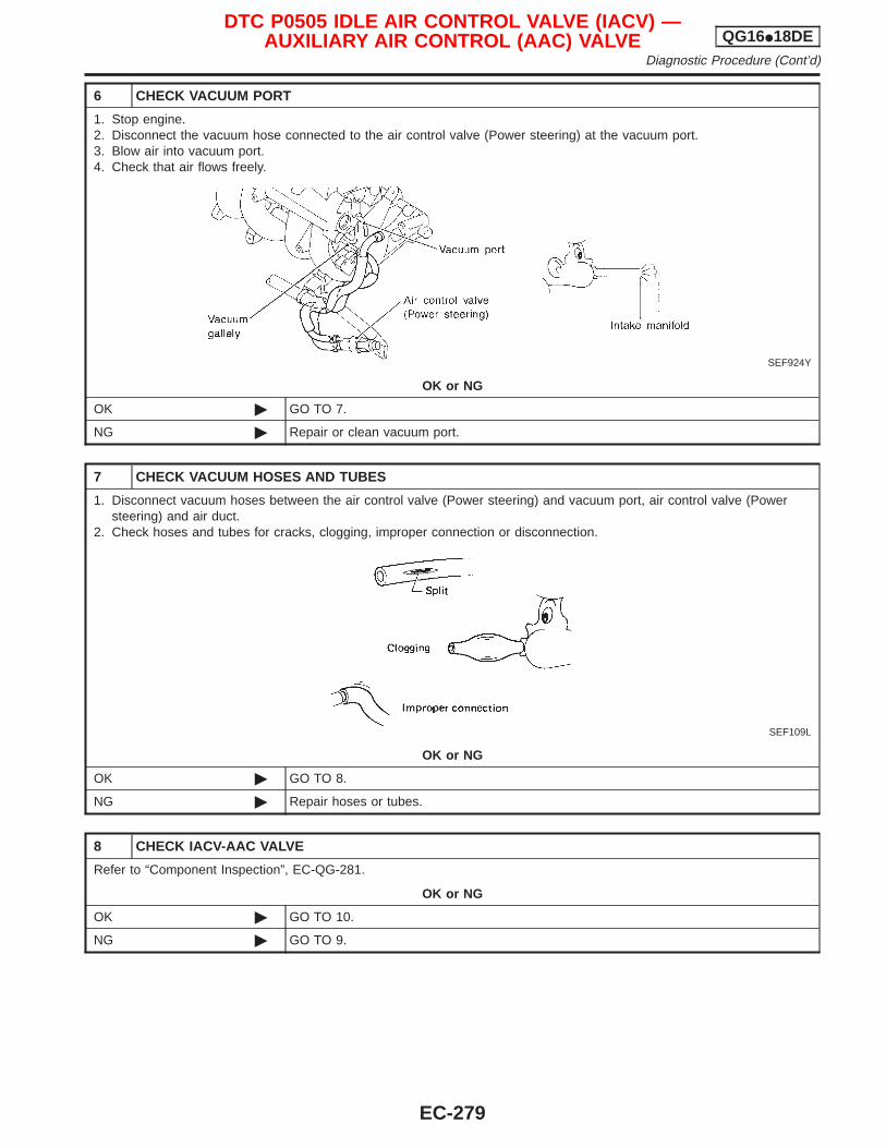
6 CHECK VACUUM PORT
1. Stop engine.2. Disconnect the vacuum hose connected to the air control valve (Power steering) at the vacuum port.3. Blow air into vacuum port.4. Check that air flows freely.
SEF924Y
OK or NG
OK © GO TO 7.
NG © Repair or clean vacuum port.
7 CHECK VACUUM HOSES AND TUBES
1. Disconnect vacuum hoses between the air control valve (Power steering) and vacuum port, air control valve (Powersteering) and air duct.
2. Check hoses and tubes for cracks, clogging, improper connection or disconnection.
SEF109L
OK or NG
OK © GO TO 8.
NG © Repair hoses or tubes.
8 CHECK IACV-AAC VALVE
Refer to “Component Inspection”, EC-QG-281.
OK or NG
OK © GO TO 10.
NG © GO TO 9.
DTC P0505 IDLE AIR CONTROL VALVE (IACV) —AUXILIARY AIR CONTROL (AAC) VALVE QG16I18DE
Diagnostic Procedure (Cont’d)
EC-279
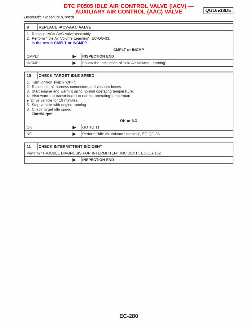
9 REPLACE IACV-AAC VALVE
1. Replace IACV-AAC valve assembly.2. Perform “Idle Air Volume Learning”, EC-QG-33.
Is the result CMPLT or INCMP?
CMPLT or INCMP
CMPLT © INSPECTION END
INCMP © Follow the instruction of “Idle Air Volume Learning”.
10 CHECK TARGET IDLE SPEED
1. Turn ignition switch “OFF”.2. Reconnect all harness connectors and vacuum hoses.3. Start engine and warm it up to normal operating temperature.4. Also warm up transmission to normal operating temperature.I Drive vehicle for 10 minutes.5. Stop vehicle with engine running.6. Check target idle speed.
700±50 rpm
OK or NG
OK © GO TO 11.
NG © Perform “Idle Air Volume Learning”, EC-QG-33.
11 CHECK INTERMITTENT INCIDENT
Perform “TROUBLE DIAGNOSIS FOR INTERMITTENT INCIDENT”, EC-QG-102.
© INSPECTION END
DTC P0505 IDLE AIR CONTROL VALVE (IACV) —AUXILIARY AIR CONTROL (AAC) VALVE QG16I18DE
Diagnostic Procedure (Cont’d)
EC-280
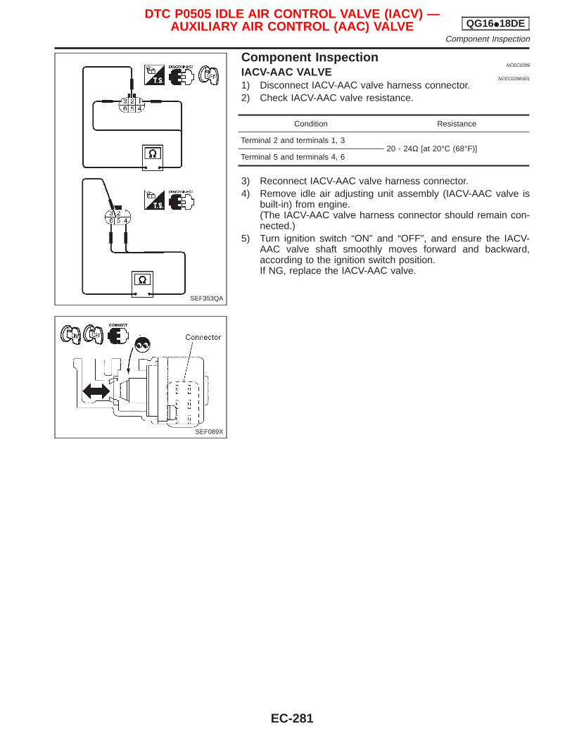
Component InspectionNCEC0286
IACV-AAC VALVENCEC0286S01
1) Disconnect IACV-AAC valve harness connector.2) Check IACV-AAC valve resistance.
Condition Resistance
Terminal 2 and terminals 1, 320 - 24Ω [at 20°C (68°F)]
Terminal 5 and terminals 4, 6
3) Reconnect IACV-AAC valve harness connector.4) Remove idle air adjusting unit assembly (IACV-AAC valve is
built-in) from engine.(The IACV-AAC valve harness connector should remain con-nected.)
5) Turn ignition switch “ON” and “OFF”, and ensure the IACV-AAC valve shaft smoothly moves forward and backward,according to the ignition switch position.If NG, replace the IACV-AAC valve.
SEF353QA
SEF089X
DTC P0505 IDLE AIR CONTROL VALVE (IACV) —AUXILIARY AIR CONTROL (AAC) VALVE QG16I18DE
Component Inspection
EC-281
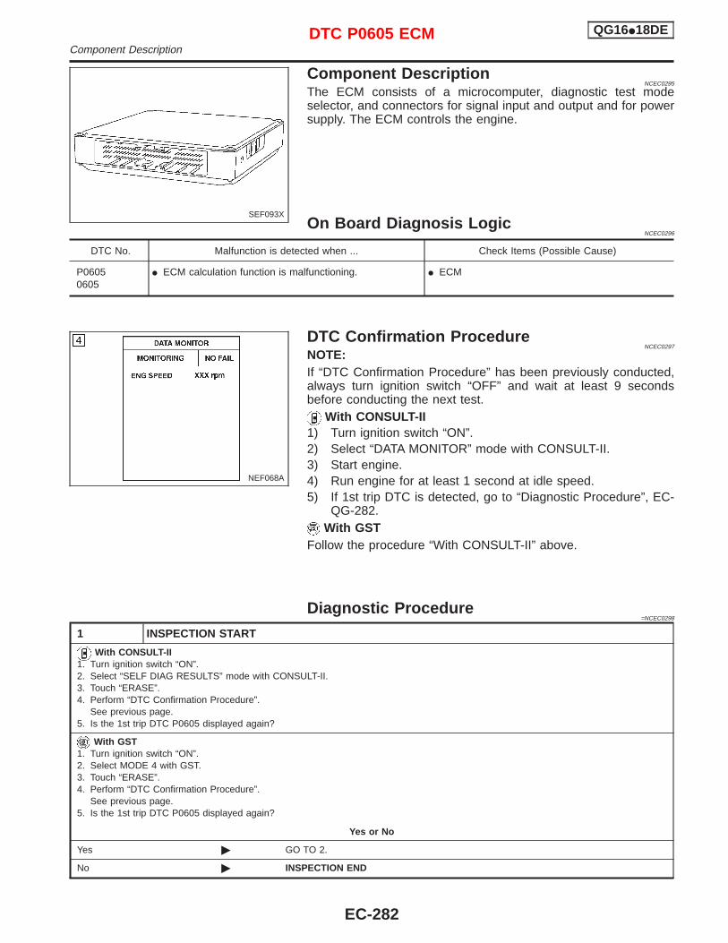
Component DescriptionNCEC0295
The ECM consists of a microcomputer, diagnostic test modeselector, and connectors for signal input and output and for powersupply. The ECM controls the engine.
On Board Diagnosis LogicNCEC0296
DTC No. Malfunction is detected when ... Check Items (Possible Cause)
P06050605
I ECM calculation function is malfunctioning. I ECM
DTC Confirmation ProcedureNCEC0297
NOTE:If “DTC Confirmation Procedure” has been previously conducted,always turn ignition switch “OFF” and wait at least 9 secondsbefore conducting the next test.
With CONSULT-II1) Turn ignition switch “ON”.2) Select “DATA MONITOR” mode with CONSULT-II.3) Start engine.4) Run engine for at least 1 second at idle speed.5) If 1st trip DTC is detected, go to “Diagnostic Procedure”, EC-
QG-282.With GST
Follow the procedure “With CONSULT-II” above.
Diagnostic Procedure=NCEC0298
1 INSPECTION START
With CONSULT-II1. Turn ignition switch “ON”.2. Select “SELF DIAG RESULTS” mode with CONSULT-II.3. Touch “ERASE”.4. Perform “DTC Confirmation Procedure”.
See previous page.5. Is the 1st trip DTC P0605 displayed again?
With GST1. Turn ignition switch “ON”.2. Select MODE 4 with GST.3. Touch “ERASE”.4. Perform “DTC Confirmation Procedure”.
See previous page.5. Is the 1st trip DTC P0605 displayed again?
Yes or No
Yes © GO TO 2.
No © INSPECTION END
SEF093X
NEF068A
DTC P0605 ECM QG16I18DEComponent Description
EC-282
2 REPLACE ECM
1. Replace ECM.2. Perform initialization of NATS (NISSAN ANTI-THEFT SYSTEM) system and registration of all NATS ignition key IDs.
Refer to “NATS (NISSAN ANTI-THEFT SYSTEM)”, EC-QG-45.3. Perform “Idle Air Volume Learning”, EC-QG-33.
Which is the result CMPLT or INCMP?
CMPLT or INCMP
CMPLT © INSPECTION END
INCMP © Follow the construction of “Idle Air Volume Learning”.
DTC P0605 ECM QG16I18DEDiagnostic Procedure (Cont’d)
EC-283
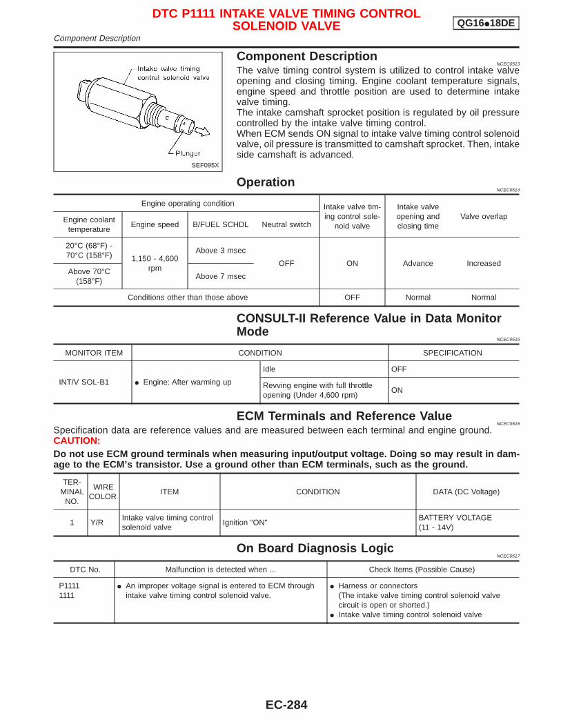
Component DescriptionNCEC0513
The valve timing control system is utilized to control intake valveopening and closing timing. Engine coolant temperature signals,engine speed and throttle position are used to determine intakevalve timing.The intake camshaft sprocket position is regulated by oil pressurecontrolled by the intake valve timing control.When ECM sends ON signal to intake valve timing control solenoidvalve, oil pressure is transmitted to camshaft sprocket. Then, intakeside camshaft is advanced.
OperationNCEC0514
Engine operating condition Intake valve tim-ing control sole-
noid valve
Intake valveopening andclosing time
Valve overlapEngine coolanttemperature
Engine speed B/FUEL SCHDL Neutral switch
20°C (68°F) -70°C (158°F) 1,150 - 4,600
rpm
Above 3 msec
OFF ON Advance IncreasedAbove 70°C
(158°F)Above 7 msec
Conditions other than those above OFF Normal Normal
CONSULT-II Reference Value in Data MonitorMode
NCEC0515
MONITOR ITEM CONDITION SPECIFICATION
INT/V SOL-B1 I Engine: After warming up
Idle OFF
Revving engine with full throttleopening (Under 4,600 rpm)
ON
ECM Terminals and Reference ValueNCEC0516
Specification data are reference values and are measured between each terminal and engine ground.CAUTION:Do not use ECM ground terminals when measuring input/output voltage. Doing so may result in dam-age to the ECM’s transistor. Use a ground other than ECM terminals, such as the ground.
TER-MINAL
NO.
WIRECOLOR
ITEM CONDITION DATA (DC Voltage)
1 Y/RIntake valve timing controlsolenoid valve
Ignition “ON”BATTERY VOLTAGE(11 - 14V)
On Board Diagnosis LogicNCEC0517
DTC No. Malfunction is detected when ... Check Items (Possible Cause)
P11111111
I An improper voltage signal is entered to ECM throughintake valve timing control solenoid valve.
I Harness or connectors(The intake valve timing control solenoid valvecircuit is open or shorted.)
I Intake valve timing control solenoid valve
SEF095X
DTC P1111 INTAKE VALVE TIMING CONTROLSOLENOID VALVE QG16I18DE
Component Description
EC-284
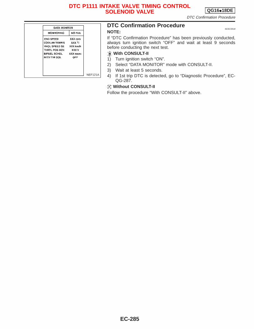
DTC Confirmation ProcedureNCEC0518
NOTE:If “DTC Confirmation Procedure” has been previously conducted,always turn ignition switch “OFF” and wait at least 9 secondsbefore conducting the next test.
With CONSULT-II1) Turn ignition switch “ON”.2) Select “DATA MONITOR” mode with CONSULT-II.3) Wait at least 5 seconds.4) If 1st trip DTC is detected, go to “Diagnostic Procedure”, EC-
QG-287.Without CONSULT-II
Follow the procedure “With CONSULT-II” above.
NEF121A
DTC P1111 INTAKE VALVE TIMING CONTROLSOLENOID VALVE QG16I18DE
DTC Confirmation Procedure
EC-285
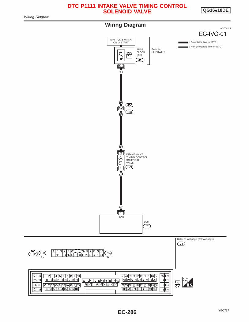
Wiring DiagramNCEC0519
YEC787
: Detectable line for DTC
: Non-detectable line for DTC
ECM
INTAKE VALVETIMING CONTROLSOLENOIDVALVE
FUSEBLOCK(J/B)
Refer toEL-POWER.
IGNITION SWITCHON or START
Refer to last page (Foldout page)
.IVC
DTC P1111 INTAKE VALVE TIMING CONTROLSOLENOID VALVE QG16I18DE
Wiring Diagram
EC-286
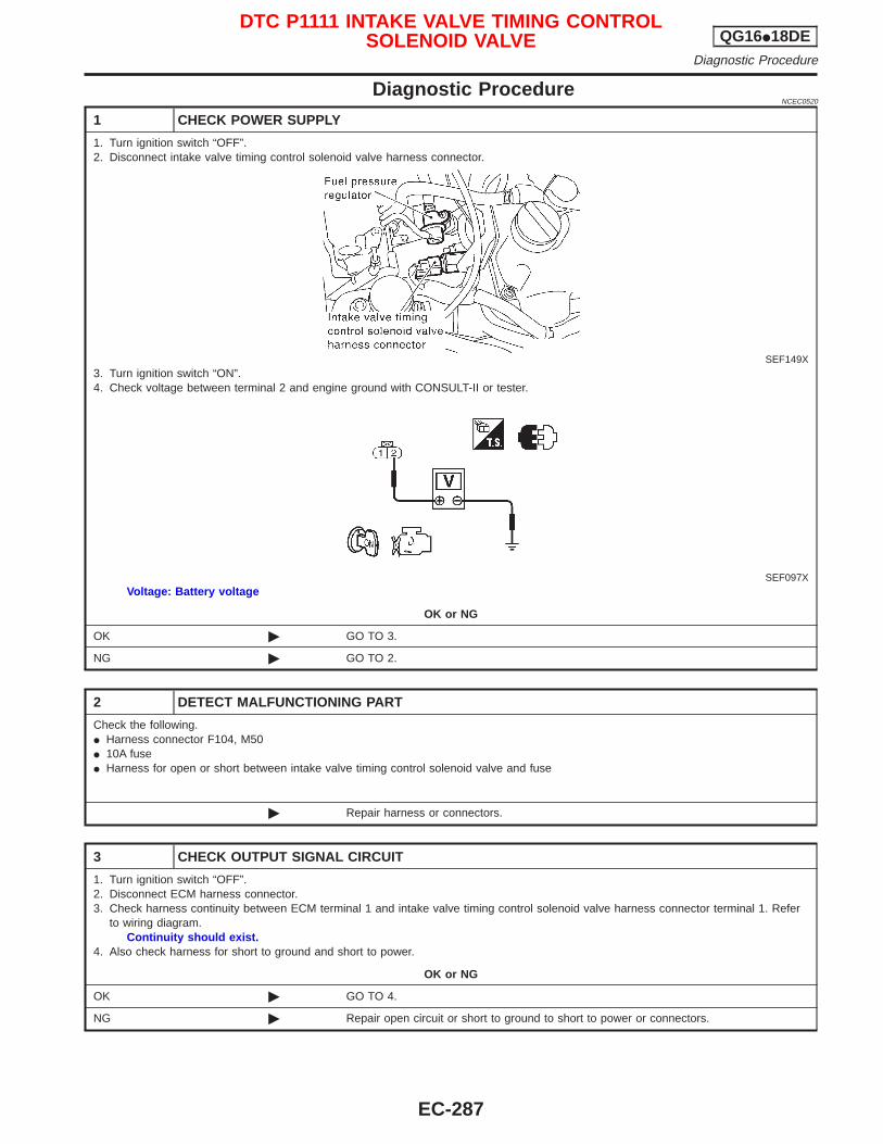
Diagnostic ProcedureNCEC0520
1 CHECK POWER SUPPLY
1. Turn ignition switch “OFF”.2. Disconnect intake valve timing control solenoid valve harness connector.
SEF149X3. Turn ignition switch “ON”.4. Check voltage between terminal 2 and engine ground with CONSULT-II or tester.
SEF097XVoltage: Battery voltage
OK or NG
OK © GO TO 3.
NG © GO TO 2.
2 DETECT MALFUNCTIONING PART
Check the following.I Harness connector F104, M50I 10A fuseI Harness for open or short between intake valve timing control solenoid valve and fuse
© Repair harness or connectors.
3 CHECK OUTPUT SIGNAL CIRCUIT
1. Turn ignition switch “OFF”.2. Disconnect ECM harness connector.3. Check harness continuity between ECM terminal 1 and intake valve timing control solenoid valve harness connector terminal 1. Refer
to wiring diagram.Continuity should exist.
4. Also check harness for short to ground and short to power.
OK or NG
OK © GO TO 4.
NG © Repair open circuit or short to ground to short to power or connectors.
DTC P1111 INTAKE VALVE TIMING CONTROLSOLENOID VALVE QG16I18DE
Diagnostic Procedure
EC-287
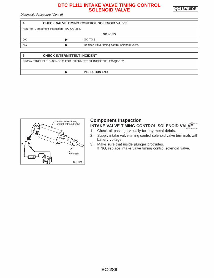
4 CHECK VALVE TIMING CONTROL SOLENOID VALVE
Refer to “Component Inspection”, EC-QG-288.
OK or NG
OK © GO TO 5.
NG © Replace valve timing control solenoid valve.
5 CHECK INTERMITTENT INCIDENT
Perform “TROUBLE DIAGNOSIS FOR INTERMITTENT INCIDENT”, EC-QG-102.
© INSPECTION END
Component InspectionNCEC0521
INTAKE VALVE TIMING CONTROL SOLENOID VALVENCEC0521S01
1. Check oil passage visually for any metal debris.2. Supply intake valve timing control solenoid valve terminals with
battery voltage.3. Make sure that inside plunger protrudes.
If NG, replace intake valve timing control solenoid valve.
SEF524T
Intake valve timingcontrol solenoid valve
PlungerFUSE
DTC P1111 INTAKE VALVE TIMING CONTROLSOLENOID VALVE QG16I18DE
Diagnostic Procedure (Cont’d)
EC-288
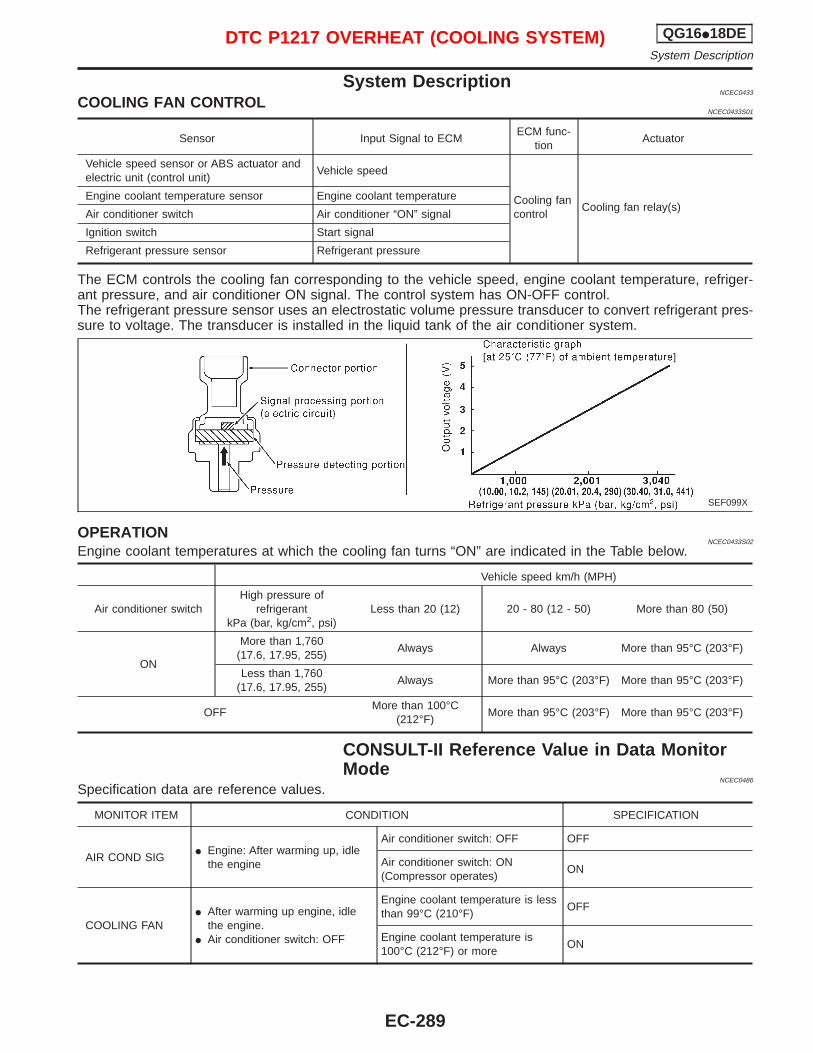
System DescriptionNCEC0433
COOLING FAN CONTROLNCEC0433S01
Sensor Input Signal to ECMECM func-
tionActuator
Vehicle speed sensor or ABS actuator andelectric unit (control unit)
Vehicle speed
Cooling fancontrol
Cooling fan relay(s)Engine coolant temperature sensor Engine coolant temperature
Air conditioner switch Air conditioner “ON” signal
Ignition switch Start signal
Refrigerant pressure sensor Refrigerant pressure
The ECM controls the cooling fan corresponding to the vehicle speed, engine coolant temperature, refriger-ant pressure, and air conditioner ON signal. The control system has ON-OFF control.The refrigerant pressure sensor uses an electrostatic volume pressure transducer to convert refrigerant pres-sure to voltage. The transducer is installed in the liquid tank of the air conditioner system.
OPERATIONNCEC0433S02
Engine coolant temperatures at which the cooling fan turns “ON” are indicated in the Table below.
Vehicle speed km/h (MPH)
Air conditioner switchHigh pressure of
refrigerantkPa (bar, kg/cm2, psi)
Less than 20 (12) 20 - 80 (12 - 50) More than 80 (50)
ON
More than 1,760(17.6, 17.95, 255)
Always Always More than 95°C (203°F)
Less than 1,760(17.6, 17.95, 255)
Always More than 95°C (203°F) More than 95°C (203°F)
OFFMore than 100°C
(212°F)More than 95°C (203°F) More than 95°C (203°F)
CONSULT-II Reference Value in Data MonitorMode
NCEC0486
Specification data are reference values.
MONITOR ITEM CONDITION SPECIFICATION
AIR COND SIGI Engine: After warming up, idle
the engine
Air conditioner switch: OFF OFF
Air conditioner switch: ON(Compressor operates)
ON
COOLING FANI After warming up engine, idle
the engine.I Air conditioner switch: OFF
Engine coolant temperature is lessthan 99°C (210°F)
OFF
Engine coolant temperature is100°C (212°F) or more
ON
SEF099X
DTC P1217 OVERHEAT (COOLING SYSTEM) QG16I18DESystem Description
EC-289
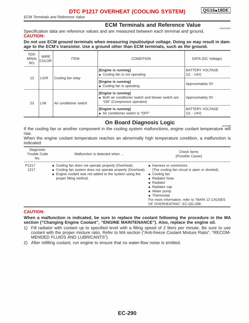
ECM Terminals and Reference Value=NCEC0487
Specification data are reference values and are measured between each terminal and ground.CAUTION:Do not use ECM ground terminals when measuring input/output voltage. Doing so may result in dam-age to the ECM’s transistor. Use a ground other than ECM terminals, such as the ground.
TER-MINAL
NO.
WIRECOLOR
ITEM CONDITION DATA (DC Voltage)
13 LG/R Cooling fan relay
[Engine is running]I Cooling fan is not operating
BATTERY VOLTAGE(11 - 14V)
[Engine is running]I Cooling fan is operating
Approximately 0V
23 L/W Air conditioner switch
[Engine is running]I Both air conditioner switch and blower switch are
“ON” (Compressor operates)Approximately 0V
[Engine is running]I Air conditioner switch is “OFF”
BATTERY VOLTAGE(11 - 14V)
On Board Diagnosis LogicNCE0488
If the cooling fan or another component in the cooling system malfunctions, engine coolant temperature willrise.When the engine coolant temperature reaches an abnormally high temperature condition, a malfunction isindicated.
DiagnosticTrouble Code
No.Malfunction is detected when ...
Check Items(Possible Cause)
P12171217
I Cooling fan does not operate properly (Overheat).I Cooling fan system does not operate properly (Overheat).I Engine coolant was not added to the system using the
proper filling method.
I Harness or connectors(The cooling fan circuit is open or shorted).
I Cooling fanI Radiator hoseI RadiatorI Radiator capI Water pumpI ThermostatFor more information, refer to “MAIN 12 CAUSESOF OVERHEATING”, EC-QG-298.
CAUTION:When a malfunction is indicated, be sure to replace the coolant following the procedure in the MAsection (“Changing Engine Coolant”, “ENGINE MAINTENANCE”). Also, replace the engine oil.1) Fill radiator with coolant up to specified level with a filling speed of 2 liters per minute. Be sure to use
coolant with the proper mixture ratio. Refer to MA section (“Anti-freeze Coolant Mixture Ratio”, “RECOM-MENDED FLUIDS AND LUBRICANTS”).
2) After refilling coolant, run engine to ensure that no water-flow noise is emitted.
DTC P1217 OVERHEAT (COOLING SYSTEM) QG16I18DEECM Terminals and Reference Value
EC-290
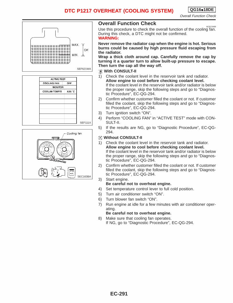
Overall Function CheckNCEC0489
Use this procedure to check the overall function of the cooling fan.During this check, a DTC might not be confirmed.WARNING:Never remove the radiator cap when the engine is hot. Seriousburns could be caused by high pressure fluid escaping fromthe radiator.Wrap a thick cloth around cap. Carefully remove the cap byturning it a quarter turn to allow built-up pressure to escape.Then turn the cap all the way off.
With CONSULT-II1) Check the coolant level in the reservoir tank and radiator.
Allow engine to cool before checking coolant level.If the coolant level in the reservoir tank and/or radiator is belowthe proper range, skip the following steps and go to “Diagnos-tic Procedure”, EC-QG-294.
2) Confirm whether customer filled the coolant or not. If customerfilled the coolant, skip the following steps and go to “Diagnos-tic Procedure”, EC-QG-294.
3) Turn ignition switch “ON”.4) Perform “COOLING FAN” in “ACTIVE TEST” mode with CON-
SULT-II.5) If the results are NG, go to “Diagnostic Procedure”, EC-QG-
294.Without CONSULT-II
1) Check the coolant level in the reservoir tank and radiator.Allow engine to cool before checking coolant level.If the coolant level in the reservoir tank and/or radiator is belowthe proper range, skip the following steps and go to “Diagnos-tic Procedure”, EC-QG-294.
2) Confirm whether customer filled the coolant or not. If customerfilled the coolant, skip the following steps and go to “Diagnos-tic Procedure”, EC-QG-294.
3) Start engine.Be careful not to overheat engine.
4) Set temperature control lever to full cold position.5) Turn air conditioner switch “ON”.6) Turn blower fan switch “ON”.7) Run engine at idle for a few minutes with air conditioner oper-
ating.Be careful not to overheat engine.
8) Make sure that cooling fan operates.If NG, go to “Diagnostic Procedure”, EC-QG-294.
SEF621WA
SEF111X
SEC163BA
DTC P1217 OVERHEAT (COOLING SYSTEM) QG16I18DEOverall Function Check
EC-291
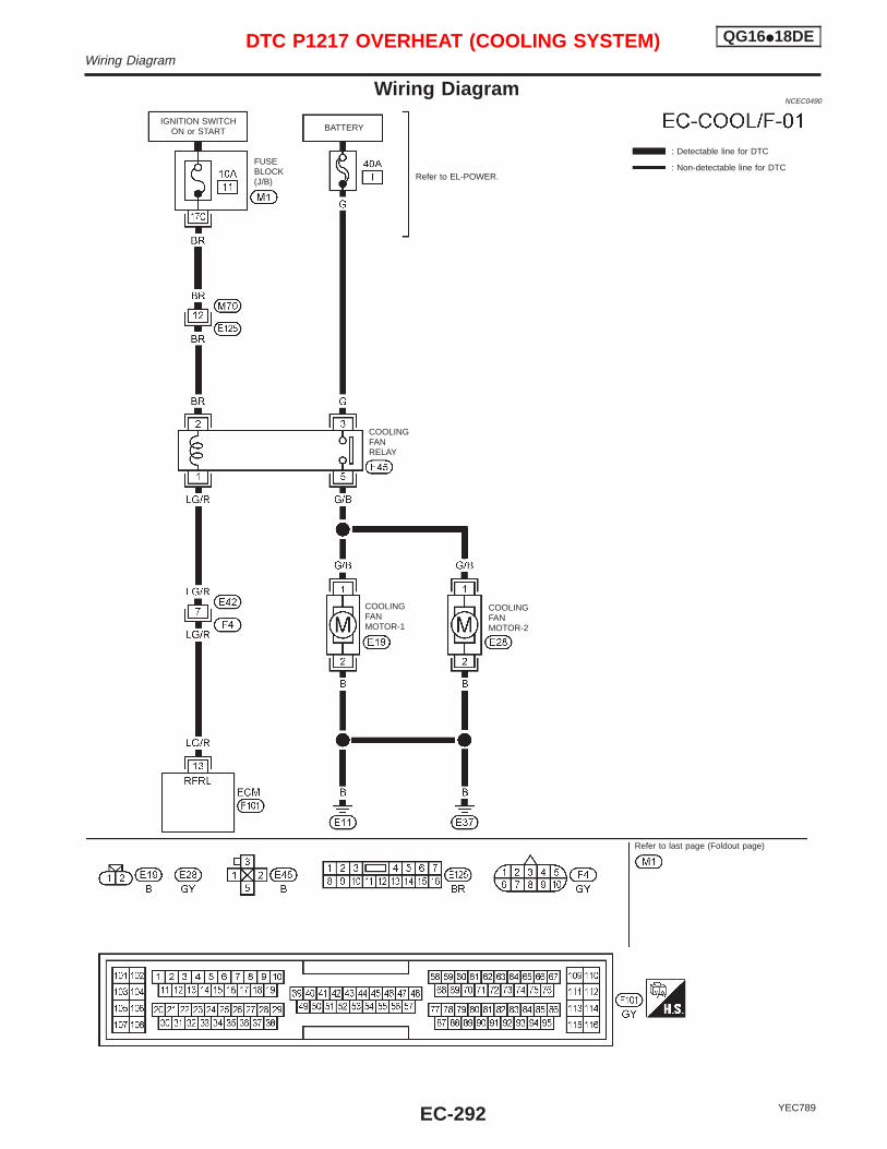
Wiring DiagramNCEC0490
YEC789
: Detectable line for DTC
: Non-detectable line for DTC
COOLINGFANRELAY
FUSEBLOCK(J/B)
COOLINGFANMOTOR-2
Refer to EL-POWER.
BATTERY
COOLINGFANMOTOR-1
IGNITION SWITCHON or START
Refer to last page (Foldout page)
DTC P1217 OVERHEAT (COOLING SYSTEM) QG16I18DEWiring Diagram
EC-292
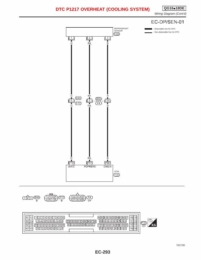
YEC790
: Detectable line for DTC
: Non-detectable line for DTC
REFRIGERANTSENSOR
ECM
DTC P1217 OVERHEAT (COOLING SYSTEM) QG16I18DEWiring Diagram (Cont’d)
EC-293
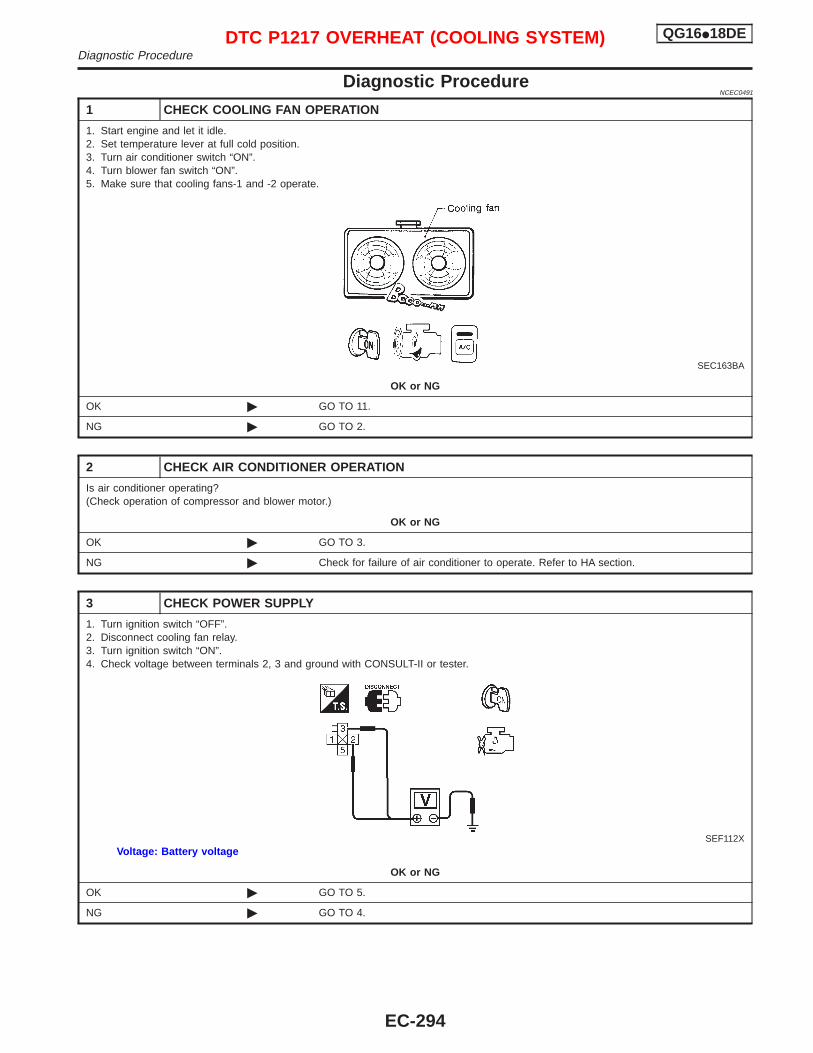
Diagnostic ProcedureNCEC0491
1 CHECK COOLING FAN OPERATION
1. Start engine and let it idle.2. Set temperature lever at full cold position.3. Turn air conditioner switch “ON”.4. Turn blower fan switch “ON”.5. Make sure that cooling fans-1 and -2 operate.
SEC163BA
OK or NG
OK © GO TO 11.
NG © GO TO 2.
2 CHECK AIR CONDITIONER OPERATION
Is air conditioner operating?(Check operation of compressor and blower motor.)
OK or NG
OK © GO TO 3.
NG © Check for failure of air conditioner to operate. Refer to HA section.
3 CHECK POWER SUPPLY
1. Turn ignition switch “OFF”.2. Disconnect cooling fan relay.3. Turn ignition switch “ON”.4. Check voltage between terminals 2, 3 and ground with CONSULT-II or tester.
SEF112XVoltage: Battery voltage
OK or NG
OK © GO TO 5.
NG © GO TO 4.
DTC P1217 OVERHEAT (COOLING SYSTEM) QG16I18DEDiagnostic Procedure
EC-294
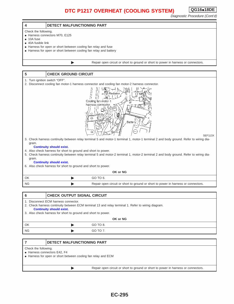
4 DETECT MALFUNCTIONING PART
Check the following.I Harness connectors M70, E125I 10A fuseI 40A fusible linkI Harness for open or short between cooling fan relay and fuseI Harness for open or short between cooling fan relay and battery
© Repair open circuit or short to ground or short to power in harness or connectors.
5 CHECK GROUND CIRCUIT
1. Turn ignition switch “OFF”.2. Disconnect cooling fan motor-1 harness connector and cooling fan motor-2 harness connector.
SEF113X3. Check harness continuity between relay terminal 5 and motor-1 terminal 1, motor-1 terminal 2 and body ground. Refer to wiring dia-
gram.Continuity should exist.
4. Also check harness for short to ground and short to power.5. Check harness continuity between relay terminal 5 and motor-2 terminal 1, motor-2 terminal 2 and body ground. Refer to wiring dia-
gram.Continuity should exist.
6. Also check harness for short to ground and short to power.
OK or NG
OK © GO TO 6.
NG © Repair open circuit or short to ground or short to power in harness or connectors.
6 CHECK OUTPUT SIGNAL CIRCUIT
1. Disconnect ECM harness connector.2. Check harness continuity between ECM terminal 13 and relay terminal 1. Refer to wiring diagram.
Continuity should exist.3. Also check harness for short to ground and short to power.
OK or NG
OK © GO TO 8.
NG © GO TO 7.
7 DETECT MALFUNCTIONING PART
Check the following.I Harness connectors E42, F4I Harness for open or short between cooling fan relay and ECM
© Repair open circuit or short to ground or short to power in harness or connectors.
DTC P1217 OVERHEAT (COOLING SYSTEM) QG16I18DEDiagnostic Procedure (Cont’d)
EC-295
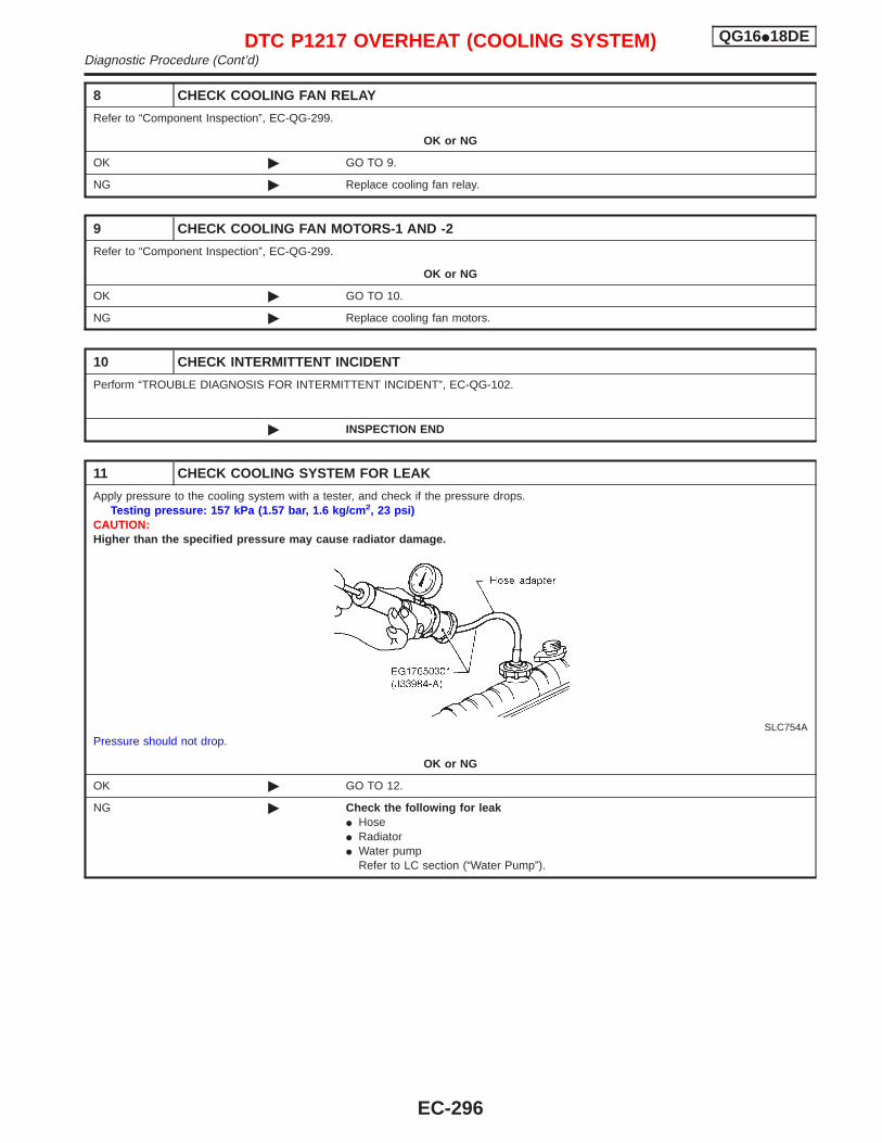
8 CHECK COOLING FAN RELAY
Refer to “Component Inspection”, EC-QG-299.
OK or NG
OK © GO TO 9.
NG © Replace cooling fan relay.
9 CHECK COOLING FAN MOTORS-1 AND -2
Refer to “Component Inspection”, EC-QG-299.
OK or NG
OK © GO TO 10.
NG © Replace cooling fan motors.
10 CHECK INTERMITTENT INCIDENT
Perform “TROUBLE DIAGNOSIS FOR INTERMITTENT INCIDENT”, EC-QG-102.
© INSPECTION END
11 CHECK COOLING SYSTEM FOR LEAK
Apply pressure to the cooling system with a tester, and check if the pressure drops.Testing pressure: 157 kPa (1.57 bar, 1.6 kg/cm 2, 23 psi)
CAUTION:Higher than the specified pressure may cause radiator damage.
SLC754APressure should not drop.
OK or NG
OK © GO TO 12.
NG © Check the following for leakI HoseI RadiatorI Water pump
Refer to LC section (“Water Pump”).
DTC P1217 OVERHEAT (COOLING SYSTEM) QG16I18DEDiagnostic Procedure (Cont’d)
EC-296
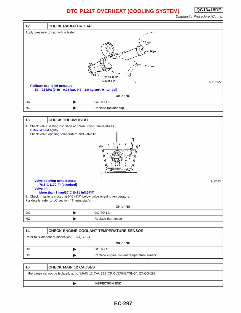
12 CHECK RADIATOR CAP
Apply pressure to cap with a tester.
SLC755ARadiator cap relief pressure:
59 - 98 kPa (0.59 - 0.98 bar, 0.6 - 1.0 kg/cm 2, 9 - 14 psi)
OK or NG
OK © GO TO 13.
NG © Replace radiator cap.
13 CHECK THERMOSTAT
1. Check valve seating condition at normal room temperatures.It should seat tightly.
2. Check valve opening temperature and valve lift.
SLC343Valve opening temperature:76.5°C (170°F) [standard]
Valve lift:More than 8 mm/90°C (0.31 in/194°F)
3. Check if valve is closed at 5°C (9°F) below valve opening temperature.For details, refer to LC section (“Thermostat”).
OK or NG
OK © GO TO 14.
NG © Replace thermostat
14 CHECK ENGINE COOLANT TEMPERATURE SENSOR
Refer to “Component Inspection”, EC-QG-124.
OK or NG
OK © GO TO 15.
NG © Replace engine coolant temperature sensor.
15 CHECK MAIN 12 CAUSES
If the cause cannot be isolated, go to “MAIN 12 CAUSES OF OVERHEATING”, EC-QG-298.
© INSPECTION END
DTC P1217 OVERHEAT (COOLING SYSTEM) QG16I18DEDiagnostic Procedure (Cont’d)
EC-297
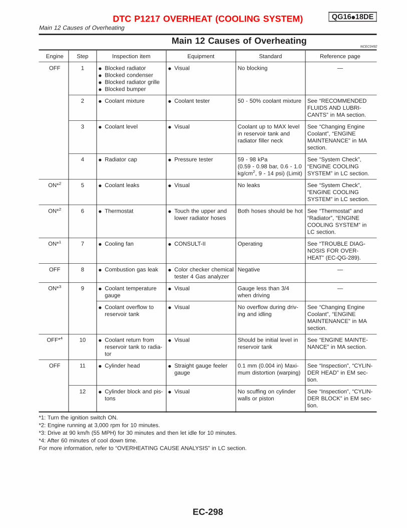
Main 12 Causes of OverheatingNCEC0492
Engine Step Inspection item Equipment Standard Reference page
OFF 1 I Blocked radiatorI Blocked condenserI Blocked radiator grilleI Blocked bumper
I Visual No blocking —
2 I Coolant mixture I Coolant tester 50 - 50% coolant mixture See “RECOMMENDEDFLUIDS AND LUBRI-CANTS” in MA section.
3 I Coolant level I Visual Coolant up to MAX levelin reservoir tank andradiator filler neck
See “Changing EngineCoolant”, “ENGINEMAINTENANCE” in MAsection.
4 I Radiator cap I Pressure tester 59 - 98 kPa(0.59 - 0.98 bar, 0.6 - 1.0kg/cm2, 9 - 14 psi) (Limit)
See “System Check”,“ENGINE COOLINGSYSTEM” in LC section.
ON*2 5 I Coolant leaks I Visual No leaks See “System Check”,“ENGINE COOLINGSYSTEM” in LC section.
ON*2 6 I Thermostat I Touch the upper andlower radiator hoses
Both hoses should be hot See “Thermostat” and“Radiator”, “ENGINECOOLING SYSTEM” inLC section.
ON*1 7 I Cooling fan I CONSULT-II Operating See “TROUBLE DIAG-NOSIS FOR OVER-HEAT” (EC-QG-289).
OFF 8 I Combustion gas leak I Color checker chemicaltester 4 Gas analyzer
Negative —
ON*3 9 I Coolant temperaturegauge
I Visual Gauge less than 3/4when driving
—
I Coolant overflow toreservoir tank
I Visual No overflow during driv-ing and idling
See “Changing EngineCoolant”, “ENGINEMAINTENANCE” in MAsection.
OFF*4 10 I Coolant return fromreservoir tank to radia-tor
I Visual Should be initial level inreservoir tank
See “ENGINE MAINTE-NANCE” in MA section.
OFF 11 I Cylinder head I Straight gauge feelergauge
0.1 mm (0.004 in) Maxi-mum distortion (warping)
See “Inspection”, “CYLIN-DER HEAD” in EM sec-tion.
12 I Cylinder block and pis-tons
I Visual No scuffing on cylinderwalls or piston
See “Inspection”, “CYLIN-DER BLOCK” in EM sec-tion.
*1: Turn the ignition switch ON.*2: Engine running at 3,000 rpm for 10 minutes.*3: Drive at 90 km/h (55 MPH) for 30 minutes and then let idle for 10 minutes.*4: After 60 minutes of cool down time.For more information, refer to “OVERHEATING CAUSE ANALYSIS” in LC section.
DTC P1217 OVERHEAT (COOLING SYSTEM) QG16I18DEMain 12 Causes of Overheating
EC-298
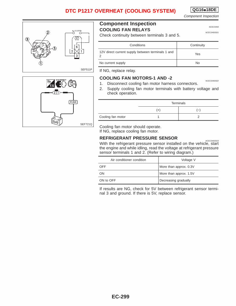
Component InspectionNCEC0493
COOLING FAN RELAYSNCEC0493S01
Check continuity between terminals 3 and 5.
Conditions Continuity
12V direct current supply between terminals 1 and2
Yes
No current supply No
If NG, replace relay.
COOLING FAN MOTORS-1 AND -2NCEC0493S02
1. Disconnect cooling fan motor harness connectors.2. Supply cooling fan motor terminals with battery voltage and
check operation.
Terminals
(+) (−)
Cooling fan motor 1 2
Cooling fan motor should operate.If NG, replace cooling fan motor.
REFRIGERANT PRESSURE SENSORNCEC0493S03
With the refrigerant pressure sensor installed on the vehicle, startthe engine and while idling, read the voltage at refrigerant pressuresensor terminals 1 and 2. (Refer to wiring diagram.)
Air conditioner condition Voltage V
OFF More than approx. 0.3V
ON More than approx. 1.5V
ON to OFF Decreasing gradually
If results are NG, check for 5V between refrigerant sensor termi-nal 3 and ground. If there is 5V, replace sensor.
SEF511P
SEF721Q
DTC P1217 OVERHEAT (COOLING SYSTEM) QG16I18DEComponent Inspection
EC-299
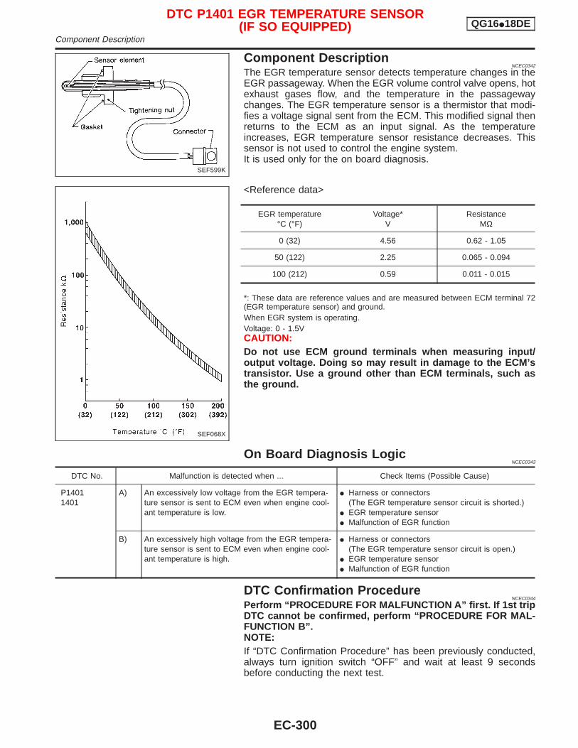
Component DescriptionNCEC0342
The EGR temperature sensor detects temperature changes in theEGR passageway. When the EGR volume control valve opens, hotexhaust gases flow, and the temperature in the passagewaychanges. The EGR temperature sensor is a thermistor that modi-fies a voltage signal sent from the ECM. This modified signal thenreturns to the ECM as an input signal. As the temperatureincreases, EGR temperature sensor resistance decreases. Thissensor is not used to control the engine system.It is used only for the on board diagnosis.
<Reference data>
EGR temperature°C (°F)
Voltage*V
ResistanceMΩ
0 (32) 4.56 0.62 - 1.05
50 (122) 2.25 0.065 - 0.094
100 (212) 0.59 0.011 - 0.015
*: These data are reference values and are measured between ECM terminal 72(EGR temperature sensor) and ground.When EGR system is operating.Voltage: 0 - 1.5VCAUTION:Do not use ECM ground terminals when measuring input/output voltage. Doing so may result in damage to the ECM’stransistor. Use a ground other than ECM terminals, such asthe ground.
On Board Diagnosis LogicNCEC0343
DTC No. Malfunction is detected when ... Check Items (Possible Cause)
P14011401
A) An excessively low voltage from the EGR tempera-ture sensor is sent to ECM even when engine cool-ant temperature is low.
I Harness or connectors(The EGR temperature sensor circuit is shorted.)
I EGR temperature sensorI Malfunction of EGR function
B) An excessively high voltage from the EGR tempera-ture sensor is sent to ECM even when engine cool-ant temperature is high.
I Harness or connectors(The EGR temperature sensor circuit is open.)
I EGR temperature sensorI Malfunction of EGR function
DTC Confirmation ProcedureNCEC0344
Perform “PROCEDURE FOR MALFUNCTION A” first. If 1st tripDTC cannot be confirmed, perform “PROCEDURE FOR MAL-FUNCTION B”.NOTE:If “DTC Confirmation Procedure” has been previously conducted,always turn ignition switch “OFF” and wait at least 9 secondsbefore conducting the next test.
SEF599K
SEF068X
DTC P1401 EGR TEMPERATURE SENSOR(IF SO EQUIPPED) QG16I18DE
Component Description
EC-300
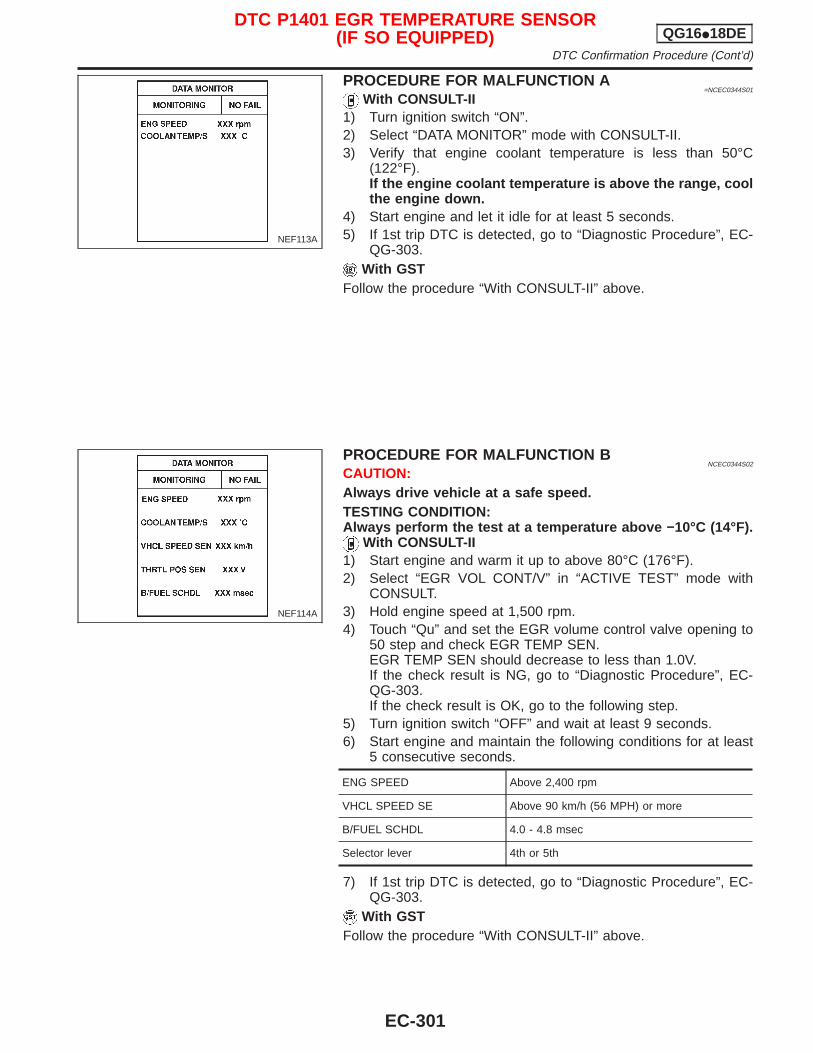
PROCEDURE FOR MALFUNCTION A=NCEC0344S01
With CONSULT-II1) Turn ignition switch “ON”.2) Select “DATA MONITOR” mode with CONSULT-II.3) Verify that engine coolant temperature is less than 50°C
(122°F).If the engine coolant temperature is above the range, coolthe engine down.
4) Start engine and let it idle for at least 5 seconds.5) If 1st trip DTC is detected, go to “Diagnostic Procedure”, EC-
QG-303.With GST
Follow the procedure “With CONSULT-II” above.
PROCEDURE FOR MALFUNCTION BNCEC0344S02
CAUTION:Always drive vehicle at a safe speed.TESTING CONDITION:Always perform the test at a temperature above −10°C (14°F).
With CONSULT-II1) Start engine and warm it up to above 80°C (176°F).2) Select “EGR VOL CONT/V” in “ACTIVE TEST” mode with
CONSULT.3) Hold engine speed at 1,500 rpm.4) Touch “Qu” and set the EGR volume control valve opening to
50 step and check EGR TEMP SEN.EGR TEMP SEN should decrease to less than 1.0V.If the check result is NG, go to “Diagnostic Procedure”, EC-QG-303.If the check result is OK, go to the following step.
5) Turn ignition switch “OFF” and wait at least 9 seconds.6) Start engine and maintain the following conditions for at least
5 consecutive seconds.
ENG SPEED Above 2,400 rpm
VHCL SPEED SE Above 90 km/h (56 MPH) or more
B/FUEL SCHDL 4.0 - 4.8 msec
Selector lever 4th or 5th
7) If 1st trip DTC is detected, go to “Diagnostic Procedure”, EC-QG-303.
With GSTFollow the procedure “With CONSULT-II” above.
NEF113A
NEF114A
DTC P1401 EGR TEMPERATURE SENSOR(IF SO EQUIPPED) QG16I18DE
DTC Confirmation Procedure (Cont’d)
EC-301
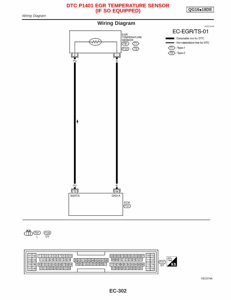
Wiring DiagramNCEC0346
YEC074A
DTC P1401 EGR TEMPERATURE SENSOR(IF SO EQUIPPED) QG16I18DE
Wiring Diagram
EC-302
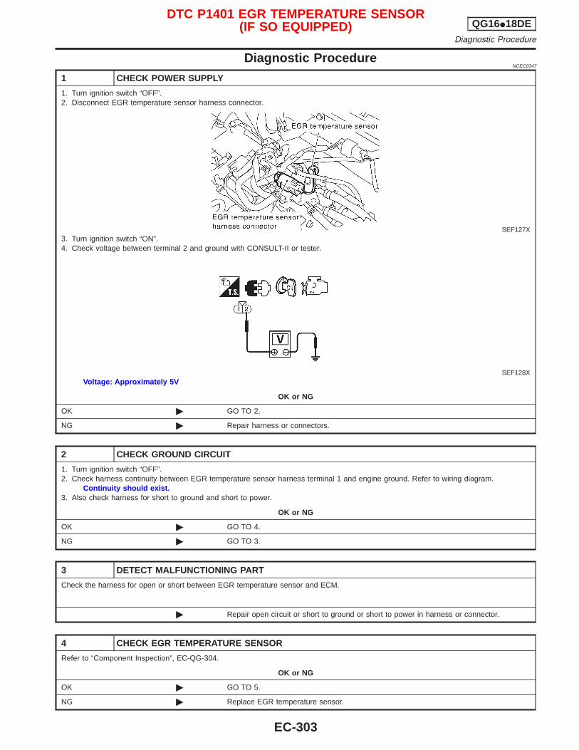
Diagnostic ProcedureNCEC0347
1 CHECK POWER SUPPLY
1. Turn ignition switch “OFF”.2. Disconnect EGR temperature sensor harness connector.
SEF127X3. Turn ignition switch “ON”.4. Check voltage between terminal 2 and ground with CONSULT-II or tester.
SEF128XVoltage: Approximately 5V
OK or NG
OK © GO TO 2.
NG © Repair harness or connectors.
2 CHECK GROUND CIRCUIT
1. Turn ignition switch “OFF”.2. Check harness continuity between EGR temperature sensor harness terminal 1 and engine ground. Refer to wiring diagram.
Continuity should exist.3. Also check harness for short to ground and short to power.
OK or NG
OK © GO TO 4.
NG © GO TO 3.
3 DETECT MALFUNCTIONING PART
Check the harness for open or short between EGR temperature sensor and ECM.
© Repair open circuit or short to ground or short to power in harness or connector.
4 CHECK EGR TEMPERATURE SENSOR
Refer to “Component Inspection”, EC-QG-304.
OK or NG
OK © GO TO 5.
NG © Replace EGR temperature sensor.
DTC P1401 EGR TEMPERATURE SENSOR(IF SO EQUIPPED) QG16I18DE
Diagnostic Procedure
EC-303
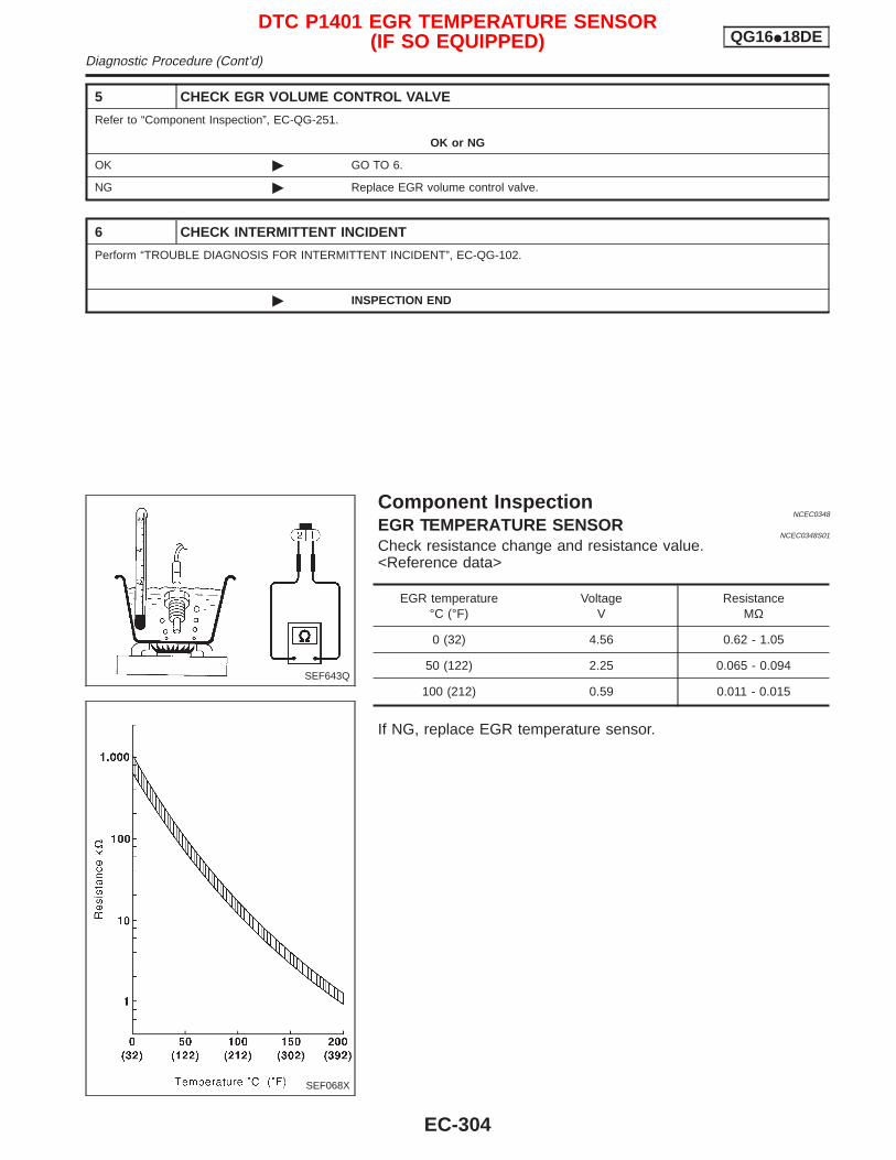
5 CHECK EGR VOLUME CONTROL VALVE
Refer to “Component Inspection”, EC-QG-251.
OK or NG
OK © GO TO 6.
NG © Replace EGR volume control valve.
6 CHECK INTERMITTENT INCIDENT
Perform “TROUBLE DIAGNOSIS FOR INTERMITTENT INCIDENT”, EC-QG-102.
© INSPECTION END
Component InspectionNCEC0348
EGR TEMPERATURE SENSORNCEC0348S01
Check resistance change and resistance value.<Reference data>
EGR temperature°C (°F)
VoltageV
ResistanceMΩ
0 (32) 4.56 0.62 - 1.05
50 (122) 2.25 0.065 - 0.094
100 (212) 0.59 0.011 - 0.015
If NG, replace EGR temperature sensor.
SEF643Q
SEF068X
DTC P1401 EGR TEMPERATURE SENSOR(IF SO EQUIPPED) QG16I18DE
Diagnostic Procedure (Cont’d)
EC-304

DescriptionNCEC0349
SYSTEM DESCRIPTIONNCEC0349S01
Sensor Input Signal to ECMECM
functionActuator
Crankshaft position sensor (POS) Engine speed
EGR control EGR volume control valve
Mass air flow sensor Amount of intake air
Engine coolant temperature sensor Engine coolant temperature
Ignition switch Start signal
Throttle position sensor Throttle position
Vehicle speed sensor or ABS actuator andelectric unit (control unit)
Vehicle speed
Battery Battery voltage
This system controls flow rate of EGR led from exhaust manifoldto intake manifold. The opening of the EGR by-pass passage in theEGR volume control valve changes to control the flow rate. Abuilt-in step motor moves the valve in steps corresponding to theECM output pulses. The opening of the valve varies for optimumengine control. The optimum value stored in the ECM is determinedby considering various engine conditions. The EGR volume controlvalve remains close under the following conditions.I Extremely light load engine operationI Mass air flow sensor malfunctionI Engine idlingI Low engine coolant temperatureI Excessively high engine coolant temperatureI High-speed engine operationI Wide open throttleI Low battery voltageI Engine starting
COMPONENT DESCRIPTIONNCEC0349S02
EGR Volume Control ValveNCEC0349S0201
The EGR volume control valve uses a step motor to control the flowrate of EGR from exhaust manifold. This motor has four windingphases. It operates according to the output pulse signal of theECM. Two windings are turned ON and OFF in sequence. Eachtime an ON pulse is issued, the valve opens or closes, changingthe flow rate. When no change in the flow rate is needed, the ECMdoes not issue the pulse signal. A certain voltage signal is issuedso that the valve remains at that particular opening.
SEF551W
SEF552W
DTC P1402 EGR FUNCTION (OPEN) (IF SO EQUIPPED) QG16I18DEDescription
EC-305
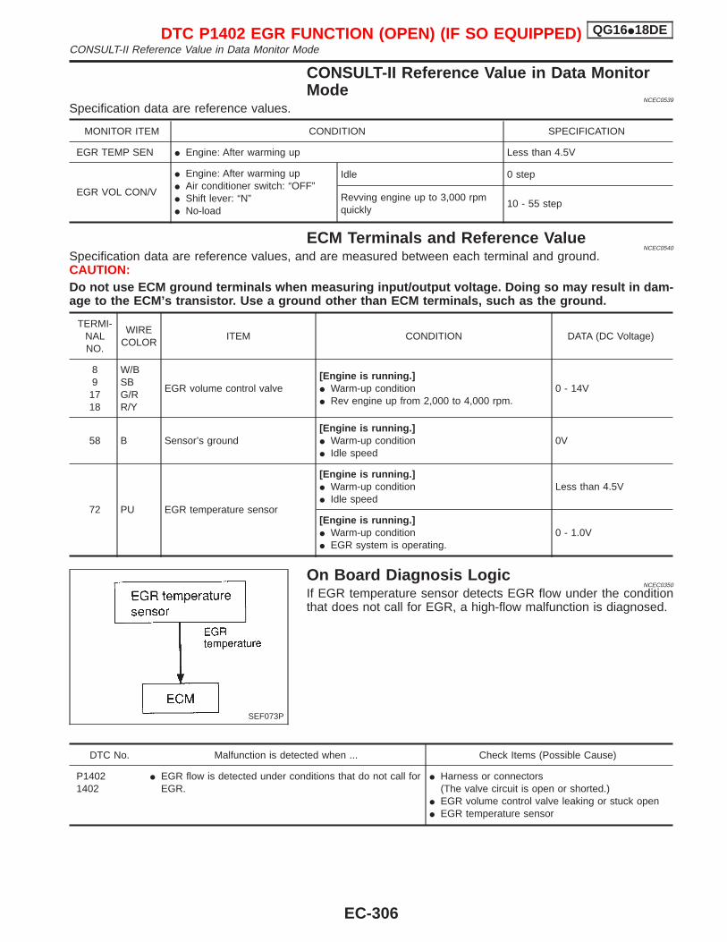
CONSULT-II Reference Value in Data MonitorMode
NCEC0539
Specification data are reference values.
MONITOR ITEM CONDITION SPECIFICATION
EGR TEMP SEN I Engine: After warming up Less than 4.5V
EGR VOL CON/V
I Engine: After warming upI Air conditioner switch: “OFF”I Shift lever: “N”I No-load
Idle 0 step
Revving engine up to 3,000 rpmquickly
10 - 55 step
ECM Terminals and Reference ValueNCEC0540
Specification data are reference values, and are measured between each terminal and ground.CAUTION:Do not use ECM ground terminals when measuring input/output voltage. Doing so may result in dam-age to the ECM’s transistor. Use a ground other than ECM terminals, such as the ground.
TERMI-NALNO.
WIRECOLOR
ITEM CONDITION DATA (DC Voltage)
89
1718
W/BSBG/RR/Y
EGR volume control valve[Engine is running.]I Warm-up conditionI Rev engine up from 2,000 to 4,000 rpm.
0 - 14V
58 B Sensor’s ground[Engine is running.]I Warm-up conditionI Idle speed
0V
72 PU EGR temperature sensor
[Engine is running.]I Warm-up conditionI Idle speed
Less than 4.5V
[Engine is running.]I Warm-up conditionI EGR system is operating.
0 - 1.0V
On Board Diagnosis LogicNCEC0350
If EGR temperature sensor detects EGR flow under the conditionthat does not call for EGR, a high-flow malfunction is diagnosed.
DTC No. Malfunction is detected when ... Check Items (Possible Cause)
P14021402
I EGR flow is detected under conditions that do not call forEGR.
I Harness or connectors(The valve circuit is open or shorted.)
I EGR volume control valve leaking or stuck openI EGR temperature sensor
SEF073P
DTC P1402 EGR FUNCTION (OPEN) (IF SO EQUIPPED) QG16I18DECONSULT-II Reference Value in Data Monitor Mode
EC-306
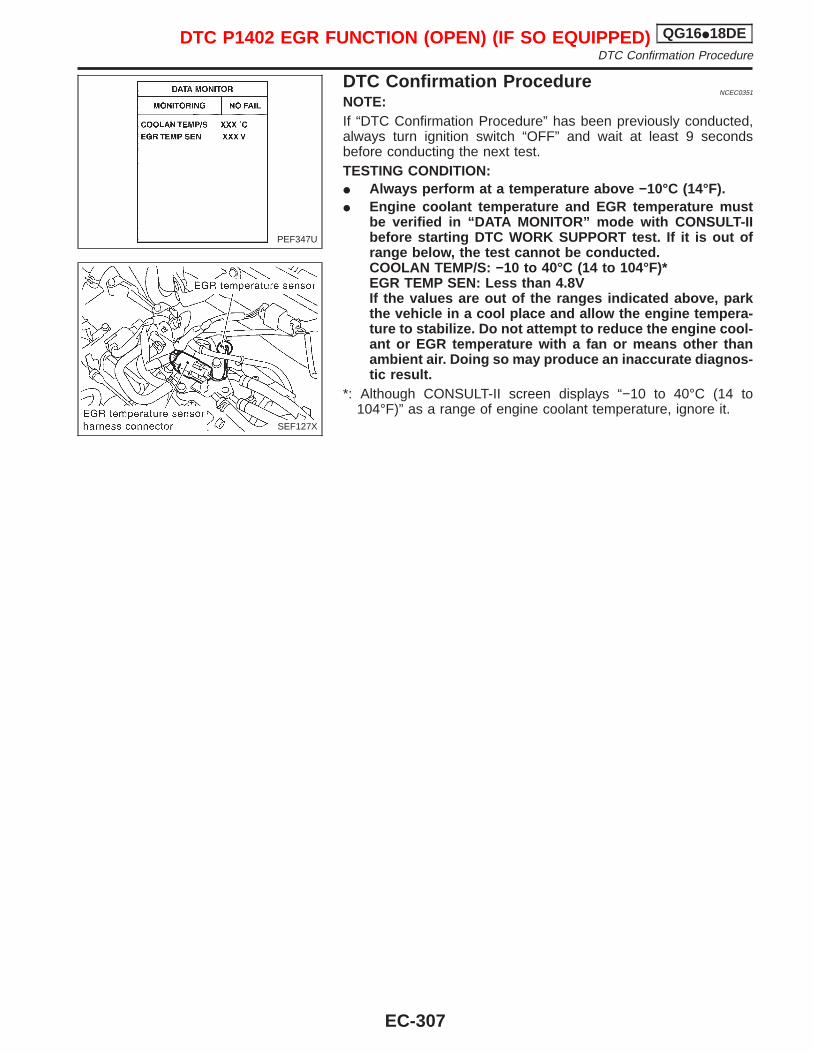
DTC Confirmation ProcedureNCEC0351
NOTE:If “DTC Confirmation Procedure” has been previously conducted,always turn ignition switch “OFF” and wait at least 9 secondsbefore conducting the next test.TESTING CONDITION:I Always perform at a temperature above −10°C (14°F).I Engine coolant temperature and EGR temperature must
be verified in “DATA MONITOR” mode with CONSULT-IIbefore starting DTC WORK SUPPORT test. If it is out ofrange below, the test cannot be conducted.COOLAN TEMP/S: −10 to 40°C (14 to 104°F)*EGR TEMP SEN: Less than 4.8VIf the values are out of the ranges indicated above, parkthe vehicle in a cool place and allow the engine tempera-ture to stabilize. Do not attempt to reduce the engine cool-ant or EGR temperature with a fan or means other thanambient air. Doing so may produce an inaccurate diagnos-tic result.
*: Although CONSULT-II screen displays “−10 to 40°C (14 to104°F)” as a range of engine coolant temperature, ignore it.
PEF347U
SEF127X
DTC P1402 EGR FUNCTION (OPEN) (IF SO EQUIPPED) QG16I18DEDTC Confirmation Procedure
EC-307
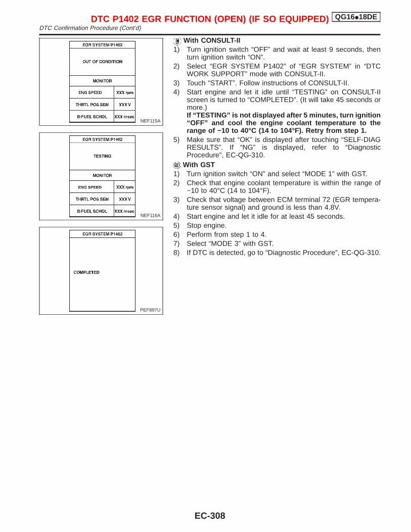
With CONSULT-II1) Turn ignition switch “OFF” and wait at least 9 seconds, then
turn ignition switch “ON”.2) Select “EGR SYSTEM P1402” of “EGR SYSTEM” in “DTC
WORK SUPPORT” mode with CONSULT-II.3) Touch “START”. Follow instructions of CONSULT-II.4) Start engine and let it idle until “TESTING” on CONSULT-II
screen is turned to “COMPLETED”. (It will take 45 seconds ormore.)If “TESTING” is not displayed after 5 minutes, turn ignition“OFF” and cool the engine coolant temperature to therange of −10 to 40°C (14 to 104°F). Retry from step 1.
5) Make sure that “OK” is displayed after touching “SELF-DIAGRESULTS”. If “NG” is displayed, refer to “DiagnosticProcedure”, EC-QG-310.
With GST1) Turn ignition switch “ON” and select “MODE 1” with GST.2) Check that engine coolant temperature is within the range of
−10 to 40°C (14 to 104°F).3) Check that voltage between ECM terminal 72 (EGR tempera-
ture sensor signal) and ground is less than 4.8V.4) Start engine and let it idle for at least 45 seconds.5) Stop engine.6) Perform from step 1 to 4.7) Select “MODE 3” with GST.8) If DTC is detected, go to “Diagnostic Procedure”, EC-QG-310.
NEF115A
NEF116A
PEF897U
DTC P1402 EGR FUNCTION (OPEN) (IF SO EQUIPPED) QG16I18DEDTC Confirmation Procedure (Cont’d)
EC-308
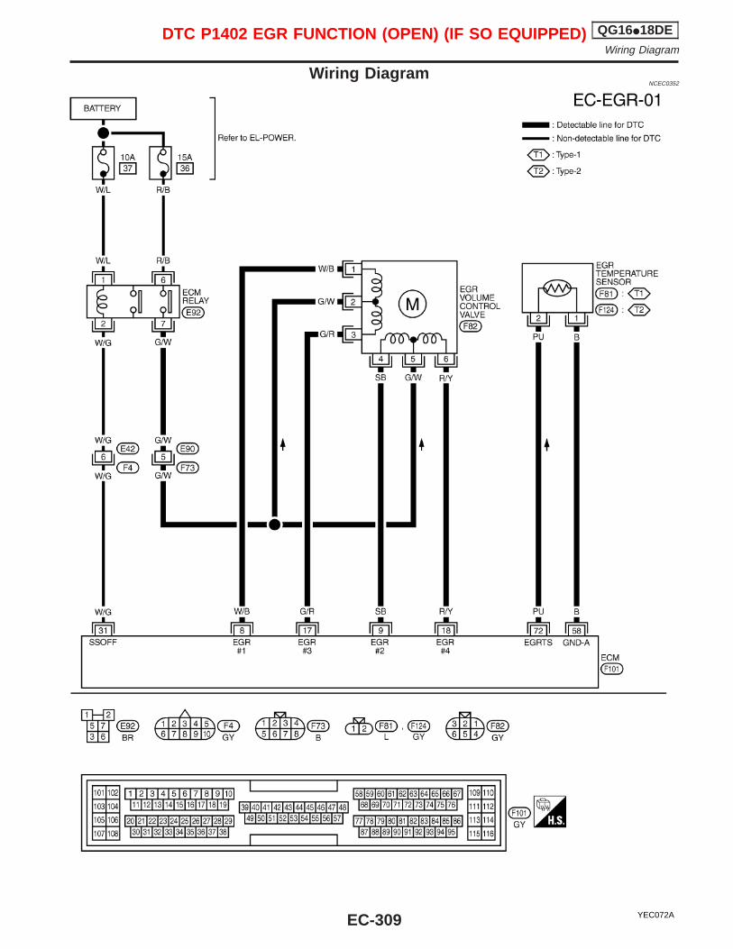
Wiring DiagramNCEC0352
YEC072A
DTC P1402 EGR FUNCTION (OPEN) (IF SO EQUIPPED) QG16I18DEWiring Diagram
EC-309
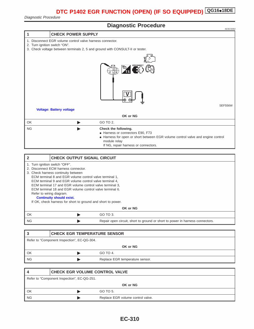
Diagnostic ProcedureNCEC0353
1 CHECK POWER SUPPLY
1. Disconnect EGR volume control valve harness connector.2. Turn ignition switch “ON”.3. Check voltage between terminals 2, 5 and ground with CONSULT-II or tester.
SEF556WVoltage: Battery voltage
OK or NG
OK © GO TO 2.
NG © Check the following.I Harness or connectors E90, F73I Harness for open or short between EGR volume control valve and engine control
module relayIf NG, repair harness or connectors.
2 CHECK OUTPUT SIGNAL CIRCUIT
1. Turn ignition switch “OFF”.2. Disconnect ECM harness connector.3. Check harness continuity between
ECM terminal 8 and EGR volume control valve terminal 1,ECM terminal 9 and EGR volume control valve terminal 4,ECM terminal 17 and EGR volume control valve terminal 3,ECM terminal 18 and EGR volume control valve terminal 6.Refer to wiring diagram.
Continuity should exist.If OK, check harness for short to ground and short to power.
OK or NG
OK © GO TO 3.
NG © Repair open circuit, short to ground or short to power in harness connectors.
3 CHECK EGR TEMPERATURE SENSOR
Refer to “Component Inspection”, EC-QG-304.
OK or NG
OK © GO TO 4.
NG © Replace EGR temperature sensor.
4 CHECK EGR VOLUME CONTROL VALVE
Refer to “Component Inspection”, EC-QG-251.
OK or NG
OK © GO TO 5.
NG © Replace EGR volume control valve.
DTC P1402 EGR FUNCTION (OPEN) (IF SO EQUIPPED) QG16I18DEDiagnostic Procedure
EC-310
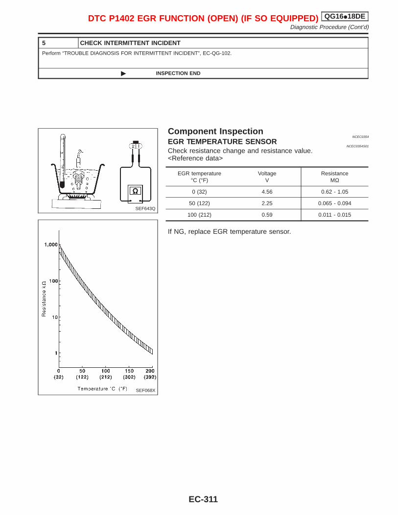
5 CHECK INTERMITTENT INCIDENT
Perform “TROUBLE DIAGNOSIS FOR INTERMITTENT INCIDENT”, EC-QG-102.
© INSPECTION END
Component InspectionNCEC0354
EGR TEMPERATURE SENSORNCEC0354S01
Check resistance change and resistance value.<Reference data>
EGR temperature°C (°F)
VoltageV
ResistanceMΩ
0 (32) 4.56 0.62 - 1.05
50 (122) 2.25 0.065 - 0.094
100 (212) 0.59 0.011 - 0.015
If NG, replace EGR temperature sensor.
SEF643Q
SEF068X
DTC P1402 EGR FUNCTION (OPEN) (IF SO EQUIPPED) QG16I18DEDiagnostic Procedure (Cont’d)
EC-311
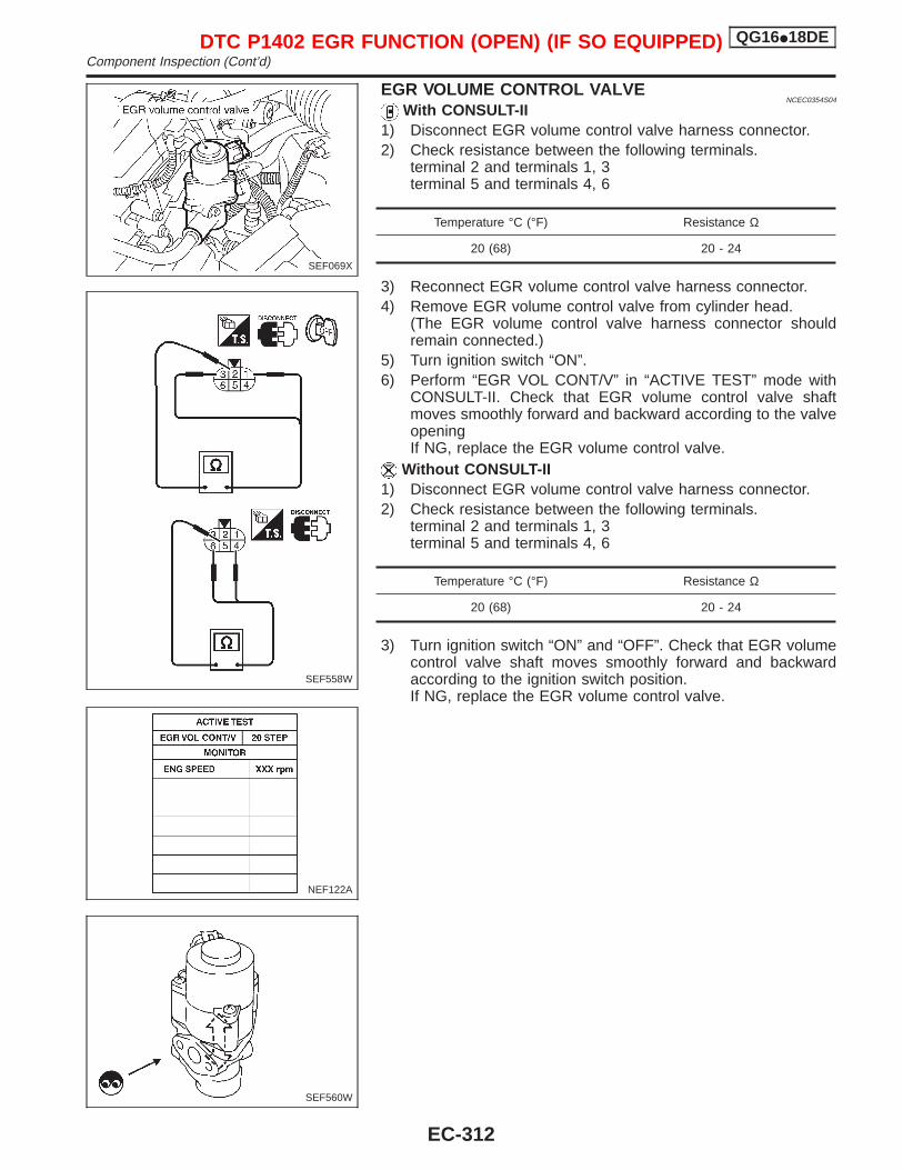
EGR VOLUME CONTROL VALVENCEC0354S04
With CONSULT-II1) Disconnect EGR volume control valve harness connector.2) Check resistance between the following terminals.
terminal 2 and terminals 1, 3terminal 5 and terminals 4, 6
Temperature °C (°F) Resistance Ω
20 (68) 20 - 24
3) Reconnect EGR volume control valve harness connector.4) Remove EGR volume control valve from cylinder head.
(The EGR volume control valve harness connector shouldremain connected.)
5) Turn ignition switch “ON”.6) Perform “EGR VOL CONT/V” in “ACTIVE TEST” mode with
CONSULT-II. Check that EGR volume control valve shaftmoves smoothly forward and backward according to the valveopeningIf NG, replace the EGR volume control valve.
Without CONSULT-II1) Disconnect EGR volume control valve harness connector.2) Check resistance between the following terminals.
terminal 2 and terminals 1, 3terminal 5 and terminals 4, 6
Temperature °C (°F) Resistance Ω
20 (68) 20 - 24
3) Turn ignition switch “ON” and “OFF”. Check that EGR volumecontrol valve shaft moves smoothly forward and backwardaccording to the ignition switch position.If NG, replace the EGR volume control valve.
SEF069X
SEF558W
NEF122A
SEF560W
DTC P1402 EGR FUNCTION (OPEN) (IF SO EQUIPPED) QG16I18DEComponent Inspection (Cont’d)
EC-312
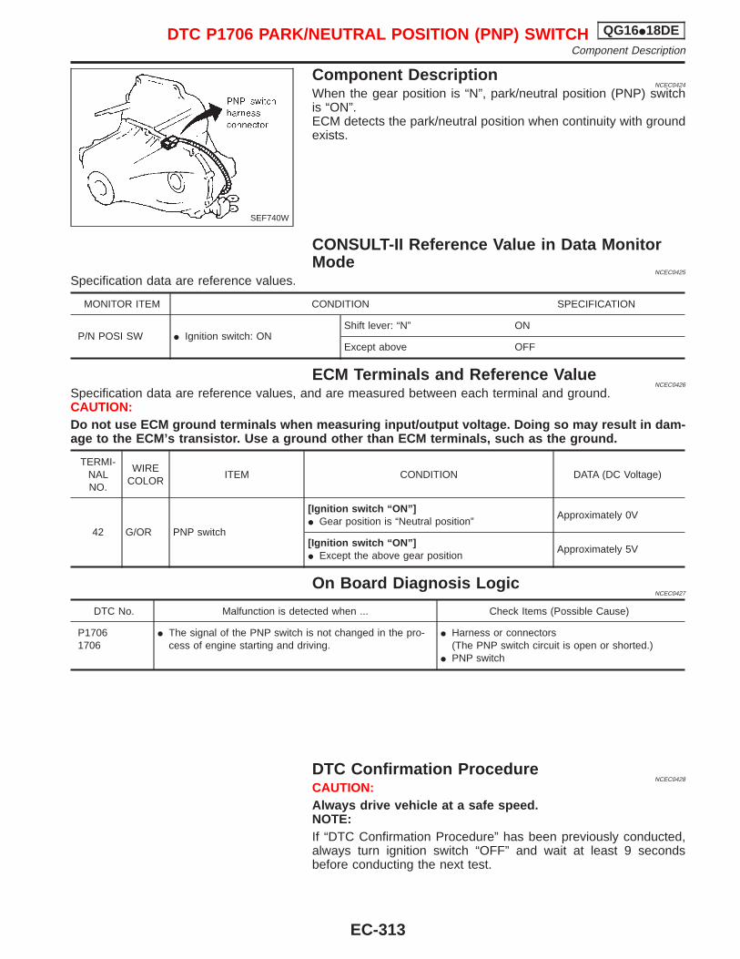
Component DescriptionNCEC0424
When the gear position is “N”, park/neutral position (PNP) switchis “ON”.ECM detects the park/neutral position when continuity with groundexists.
CONSULT-II Reference Value in Data MonitorMode
NCEC0425
Specification data are reference values.
MONITOR ITEM CONDITION SPECIFICATION
P/N POSI SW I Ignition switch: ONShift lever: “N” ON
Except above OFF
ECM Terminals and Reference ValueNCEC0426
Specification data are reference values, and are measured between each terminal and ground.CAUTION:Do not use ECM ground terminals when measuring input/output voltage. Doing so may result in dam-age to the ECM’s transistor. Use a ground other than ECM terminals, such as the ground.
TERMI-NALNO.
WIRECOLOR
ITEM CONDITION DATA (DC Voltage)
42 G/OR PNP switch
[Ignition switch “ON”]I Gear position is “Neutral position”
Approximately 0V
[Ignition switch “ON”]I Except the above gear position
Approximately 5V
On Board Diagnosis LogicNCEC0427
DTC No. Malfunction is detected when ... Check Items (Possible Cause)
P17061706
I The signal of the PNP switch is not changed in the pro-cess of engine starting and driving.
I Harness or connectors(The PNP switch circuit is open or shorted.)
I PNP switch
DTC Confirmation ProcedureNCEC0428
CAUTION:Always drive vehicle at a safe speed.NOTE:If “DTC Confirmation Procedure” has been previously conducted,always turn ignition switch “OFF” and wait at least 9 secondsbefore conducting the next test.
SEF740W
DTC P1706 PARK/NEUTRAL POSITION (PNP) SWITCH QG16I18DEComponent Description
EC-313
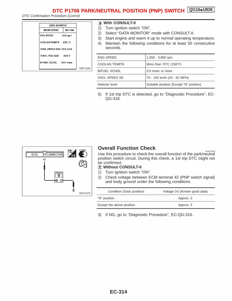
With CONSULT-II1) Turn ignition switch “ON”.2) Select “DATA MONITOR” mode with CONSULT-II.3) Start engine and warm it up to normal operating temperature.4) Maintain the following conditions for at least 50 consecutive
seconds.
ENG SPEED 1,550 - 3,800 rpm
COOLAN TEMP/S More than 70°C (158°F)
B/FUEL SCHDL 3.0 msec or more
VHCL SPEED SE 70 - 100 km/h (43 - 62 MPH)
Selector lever Suitable position (Except “N” position)
5) If 1st trip DTC is detected, go to “Diagnostic Procedure”, EC-QG-316.
Overall Function CheckNCEC0429
Use this procedure to check the overall function of the park/neutralposition switch circuit. During this check, a 1st trip DTC might notbe confirmed.
Without CONSULT-II1) Turn ignition switch “ON”.2) Check voltage between ECM terminal 42 (PNP switch signal)
and body ground under the following conditions.
Condition (Gear position) Voltage (V) (Known good data)
“N” position Approx. 0
Except the above position Approx. 5
3) If NG, go to “Diagnostic Procedure”, EC-QG-316.
NEF118A
SEF137X
DTC P1706 PARK/NEUTRAL POSITION (PNP) SWITCH QG16I18DEDTC Confirmation Procedure (Cont’d)
EC-314
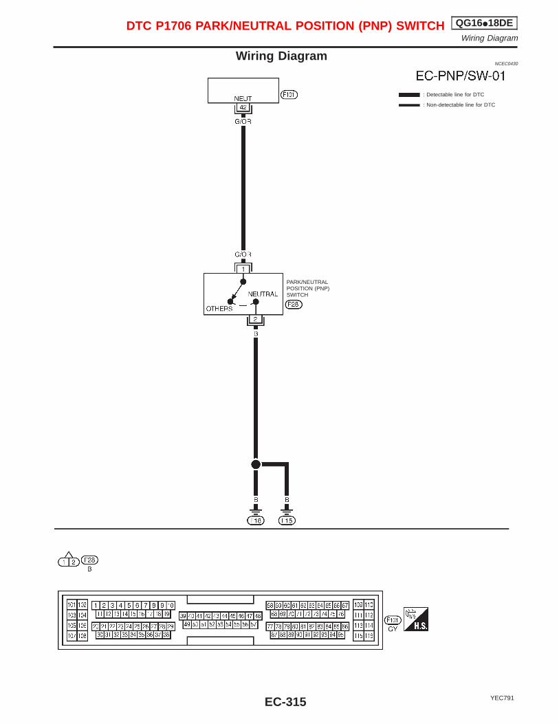
Wiring DiagramNCEC0430
YEC791
: Detectable line for DTC
: Non-detectable line for DTC
PARK/NEUTRALPOSITION (PNP)SWITCH
DTC P1706 PARK/NEUTRAL POSITION (PNP) SWITCH QG16I18DEWiring Diagram
EC-315
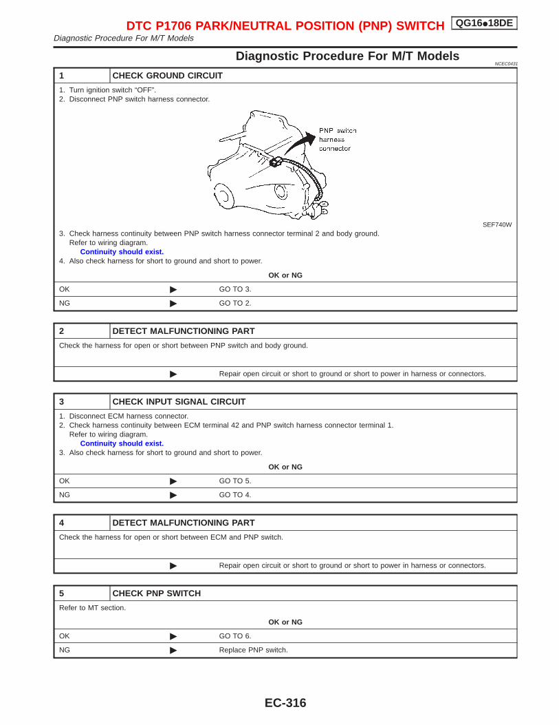
Diagnostic Procedure For M/T ModelsNCEC0431
1 CHECK GROUND CIRCUIT
1. Turn ignition switch “OFF”.2. Disconnect PNP switch harness connector.
SEF740W3. Check harness continuity between PNP switch harness connector terminal 2 and body ground.
Refer to wiring diagram.Continuity should exist.
4. Also check harness for short to ground and short to power.
OK or NG
OK © GO TO 3.
NG © GO TO 2.
2 DETECT MALFUNCTIONING PART
Check the harness for open or short between PNP switch and body ground.
© Repair open circuit or short to ground or short to power in harness or connectors.
3 CHECK INPUT SIGNAL CIRCUIT
1. Disconnect ECM harness connector.2. Check harness continuity between ECM terminal 42 and PNP switch harness connector terminal 1.
Refer to wiring diagram.Continuity should exist.
3. Also check harness for short to ground and short to power.
OK or NG
OK © GO TO 5.
NG © GO TO 4.
4 DETECT MALFUNCTIONING PART
Check the harness for open or short between ECM and PNP switch.
© Repair open circuit or short to ground or short to power in harness or connectors.
5 CHECK PNP SWITCH
Refer to MT section.
OK or NG
OK © GO TO 6.
NG © Replace PNP switch.
DTC P1706 PARK/NEUTRAL POSITION (PNP) SWITCH QG16I18DEDiagnostic Procedure For M/T Models
EC-316
6 CHECK INTERMITTENT INCIDENT
Perform “TROUBLE DIAGNOSIS FOR INTERMITTENT INCIDENT”, EC-QG-102.
© INSPECTION END
DTC P1706 PARK/NEUTRAL POSITION (PNP) SWITCH QG16I18DEDiagnostic Procedure For M/T Models (Cont’d)
EC-317
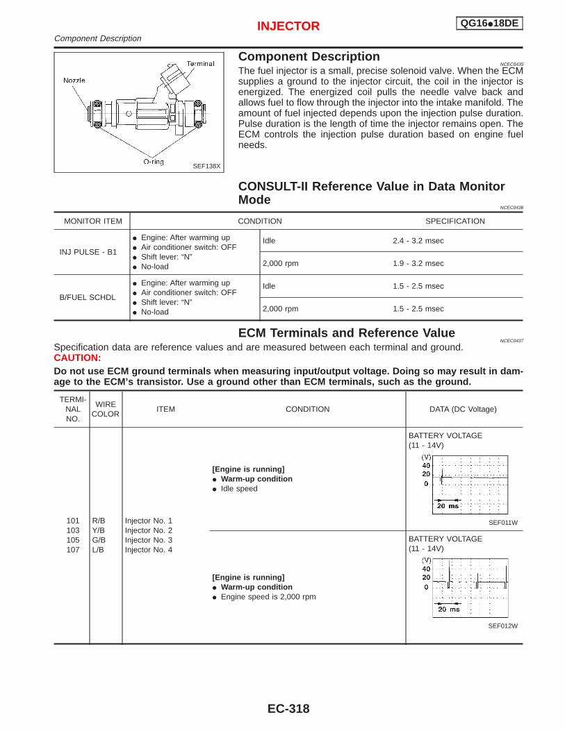
Component DescriptionNCEC0435
The fuel injector is a small, precise solenoid valve. When the ECMsupplies a ground to the injector circuit, the coil in the injector isenergized. The energized coil pulls the needle valve back andallows fuel to flow through the injector into the intake manifold. Theamount of fuel injected depends upon the injection pulse duration.Pulse duration is the length of time the injector remains open. TheECM controls the injection pulse duration based on engine fuelneeds.
CONSULT-II Reference Value in Data MonitorMode
NCEC0436
MONITOR ITEM CONDITION SPECIFICATION
INJ PULSE - B1
I Engine: After warming upI Air conditioner switch: OFFI Shift lever: “N”I No-load
Idle 2.4 - 3.2 msec
2,000 rpm 1.9 - 3.2 msec
B/FUEL SCHDL
I Engine: After warming upI Air conditioner switch: OFFI Shift lever: “N”I No-load
Idle 1.5 - 2.5 msec
2,000 rpm 1.5 - 2.5 msec
ECM Terminals and Reference ValueNCEC0437
Specification data are reference values and are measured between each terminal and ground.CAUTION:Do not use ECM ground terminals when measuring input/output voltage. Doing so may result in dam-age to the ECM’s transistor. Use a ground other than ECM terminals, such as the ground.
TERMI-NALNO.
WIRECOLOR
ITEM CONDITION DATA (DC Voltage)
101103105107
R/BY/BG/BL/B
Injector No. 1Injector No. 2Injector No. 3Injector No. 4
[Engine is running]I Warm-up conditionI Idle speed
BATTERY VOLTAGE(11 - 14V)
SEF011W
[Engine is running]I Warm-up conditionI Engine speed is 2,000 rpm
BATTERY VOLTAGE(11 - 14V)
SEF012W
SEF138X
INJECTOR QG16I18DEComponent Description
EC-318
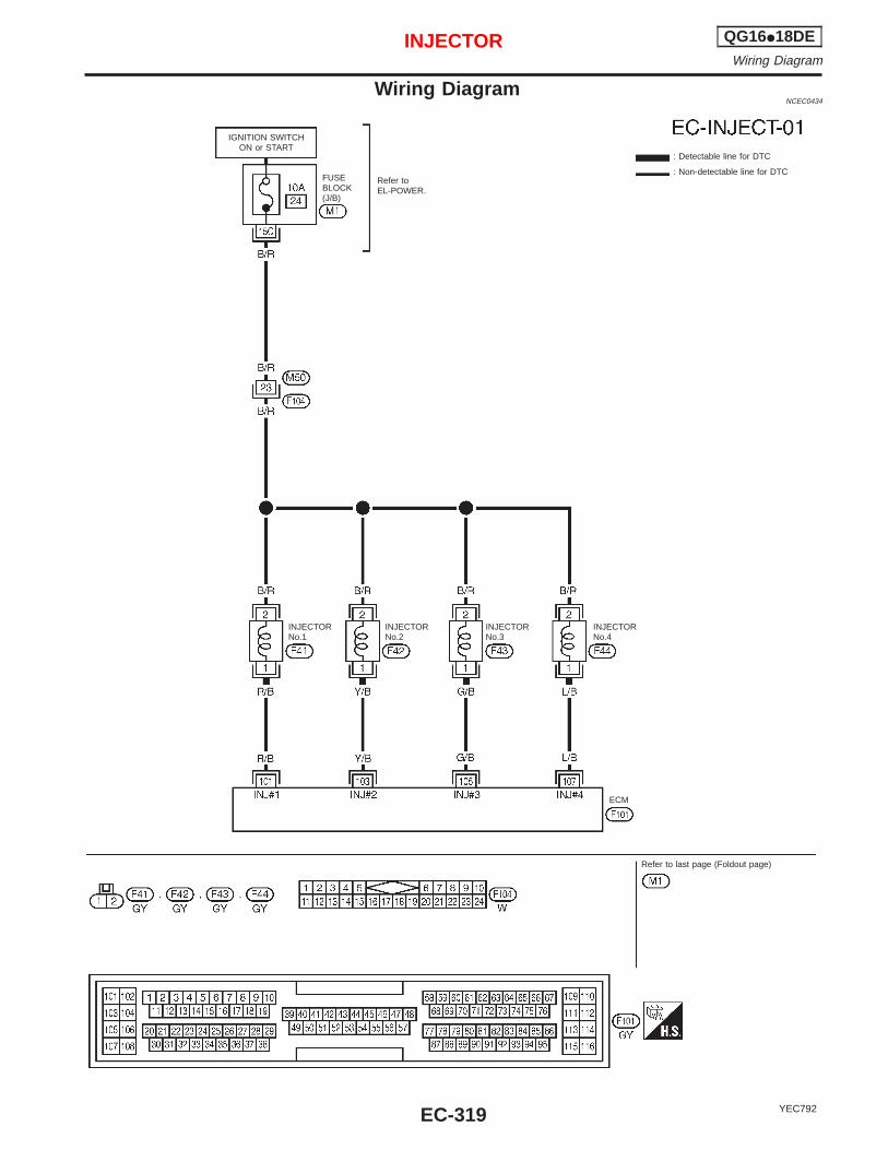
Wiring DiagramNCEC0434
YEC792
IGNITION SWITCHON or START
Refer toEL-POWER.
: Detectable line for DTC
: Non-detectable line for DTCFUSEBLOCK(J/B)
ECM
Refer to last page (Foldout page)
INJECTORNo.1
INJECTORNo.2
INJECTORNo.3
INJECTORNo.4
INJECTOR QG16I18DEWiring Diagram
EC-319
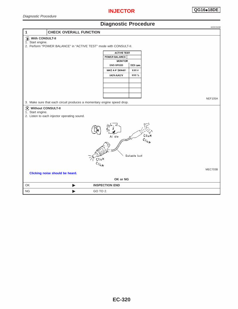
Diagnostic ProcedureNCEC0438
1 CHECK OVERALL FUNCTION
With CONSULT-II1. Start engine.2. Perform “POWER BALANCE” in “ACTIVE TEST” mode with CONSULT-II.
NEF105A3. Make sure that each circuit produces a momentary engine speed drop.
Without CONSULT-II1. Start engine.2. Listen to each injector operating sound.
MEC703BClicking noise should be heard.
OK or NG
OK © INSPECTION END
NG © GO TO 2.
INJECTOR QG16I18DEDiagnostic Procedure
EC-320
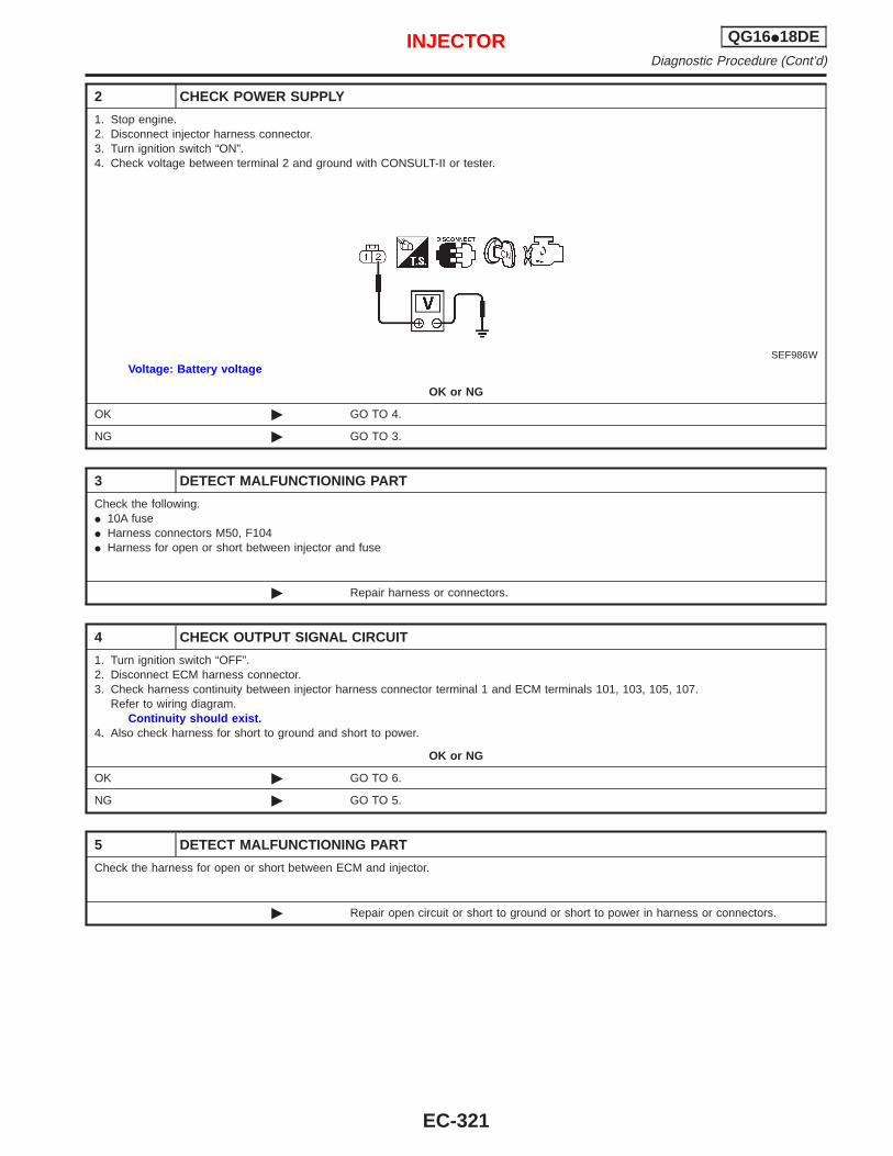
2 CHECK POWER SUPPLY
1. Stop engine.2. Disconnect injector harness connector.3. Turn ignition switch “ON”.4. Check voltage between terminal 2 and ground with CONSULT-II or tester.
SEF986WVoltage: Battery voltage
OK or NG
OK © GO TO 4.
NG © GO TO 3.
3 DETECT MALFUNCTIONING PART
Check the following.I 10A fuseI Harness connectors M50, F104I Harness for open or short between injector and fuse
© Repair harness or connectors.
4 CHECK OUTPUT SIGNAL CIRCUIT
1. Turn ignition switch “OFF”.2. Disconnect ECM harness connector.3. Check harness continuity between injector harness connector terminal 1 and ECM terminals 101, 103, 105, 107.
Refer to wiring diagram.Continuity should exist.
4. Also check harness for short to ground and short to power.
OK or NG
OK © GO TO 6.
NG © GO TO 5.
5 DETECT MALFUNCTIONING PART
Check the harness for open or short between ECM and injector.
© Repair open circuit or short to ground or short to power in harness or connectors.
INJECTOR QG16I18DEDiagnostic Procedure (Cont’d)
EC-321
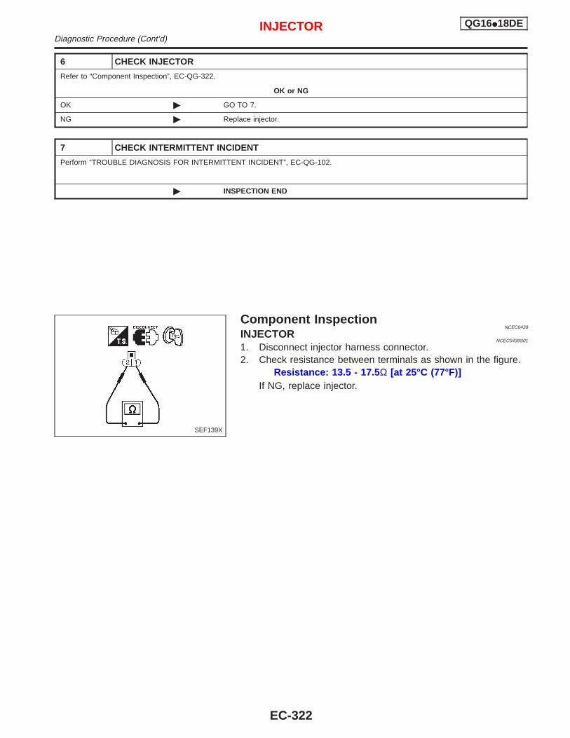
6 CHECK INJECTOR
Refer to “Component Inspection”, EC-QG-322.
OK or NG
OK © GO TO 7.
NG © Replace injector.
7 CHECK INTERMITTENT INCIDENT
Perform “TROUBLE DIAGNOSIS FOR INTERMITTENT INCIDENT”, EC-QG-102.
© INSPECTION END
Component InspectionNCEC0439
INJECTORNCEC0439S01
1. Disconnect injector harness connector.2. Check resistance between terminals as shown in the figure.
Resistance: 13.5 - 17.5 Ω [at 25°C (77°F)]If NG, replace injector.
SEF139X
INJECTOR QG16I18DEDiagnostic Procedure (Cont’d)
EC-322
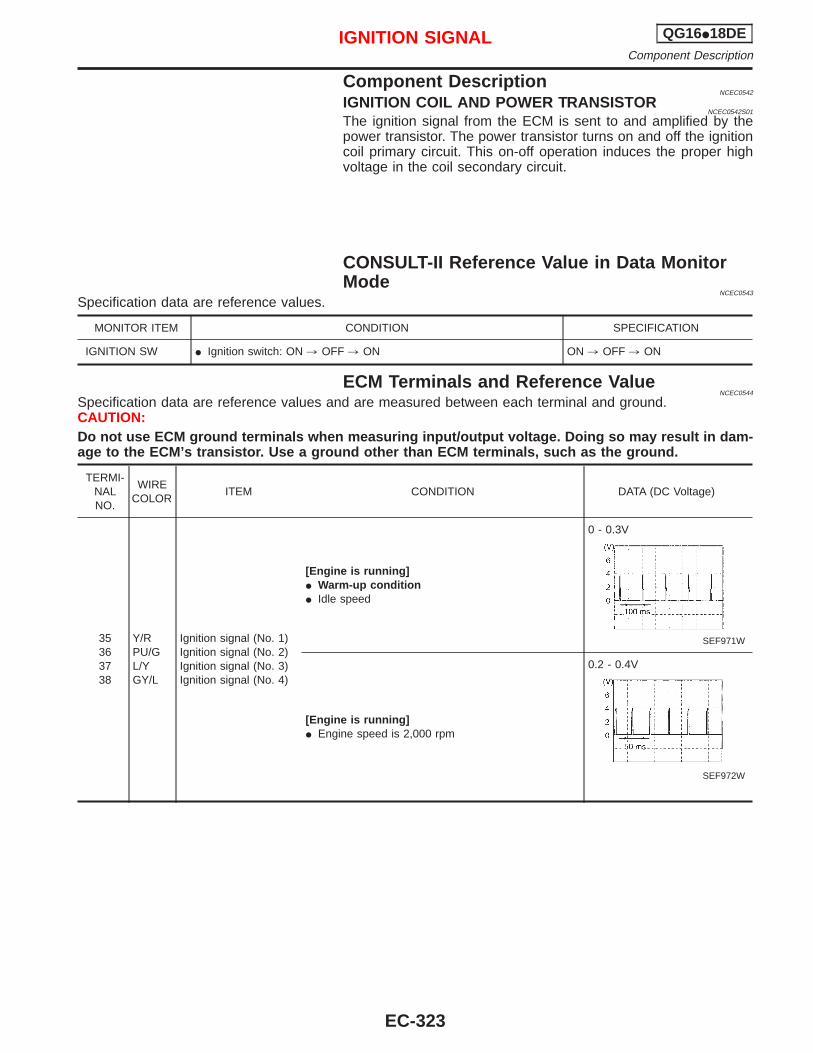
Component DescriptionNCEC0542
IGNITION COIL AND POWER TRANSISTORNCEC0542S01
The ignition signal from the ECM is sent to and amplified by thepower transistor. The power transistor turns on and off the ignitioncoil primary circuit. This on-off operation induces the proper highvoltage in the coil secondary circuit.
CONSULT-II Reference Value in Data MonitorMode
NCEC0543
Specification data are reference values.
MONITOR ITEM CONDITION SPECIFICATION
IGNITION SW I Ignition switch: ON , OFF , ON ON , OFF , ON
ECM Terminals and Reference ValueNCEC0544
Specification data are reference values and are measured between each terminal and ground.CAUTION:Do not use ECM ground terminals when measuring input/output voltage. Doing so may result in dam-age to the ECM’s transistor. Use a ground other than ECM terminals, such as the ground.
TERMI-NALNO.
WIRECOLOR
ITEM CONDITION DATA (DC Voltage)
35363738
Y/RPU/GL/YGY/L
Ignition signal (No. 1)Ignition signal (No. 2)Ignition signal (No. 3)Ignition signal (No. 4)
[Engine is running]I Warm-up conditionI Idle speed
0 - 0.3V
SEF971W
[Engine is running]I Engine speed is 2,000 rpm
0.2 - 0.4V
SEF972W
IGNITION SIGNAL QG16I18DEComponent Description
EC-323
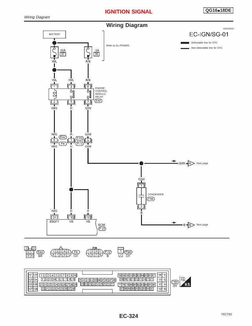
Wiring DiagramNCEC0545
YEC793
ENGINECONTROLMODULERELAY
CONDENSER
Refer to EL-POWER.
BATTERY
: Detectable line for DTC
: Non-detectable line for DTC
Next page
Next page
IGNITION SIGNAL QG16I18DEWiring Diagram
EC-324
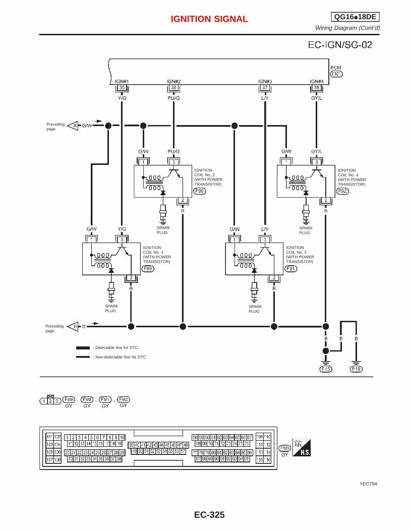
YEC794
Precedingpage
IGNITIONCOIL No. 4(WITH POWERTRANSISTOR)
IGNITIONCOIL No. 2(WITH POWERTRANSISTOR)
SPARKPLUG
IGNITIONCOIL No. 1(WITH POWERTRANSISTOR)
IGNITIONCOIL No. 3(WITH POWERTRANSISTOR)
SPARKPLUG
SPARKPLUG
SPARKPLUG
Precedingpage
: Detectable line for DTC
: Non-detectable line for DTC
IGNITION SIGNAL QG16I18DEWiring Diagram (Cont’d)
EC-325
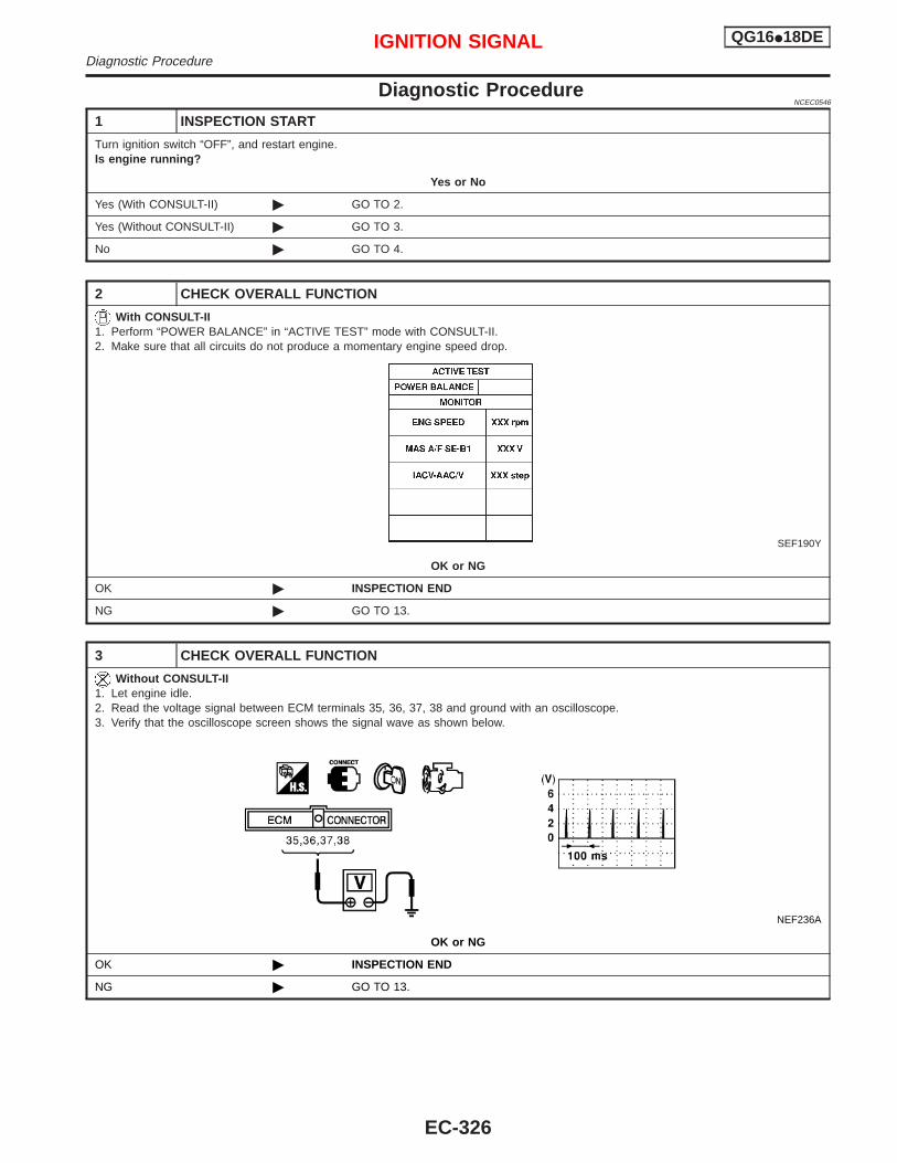
Diagnostic ProcedureNCEC0546
1 INSPECTION START
Turn ignition switch “OFF”, and restart engine.Is engine running?
Yes or No
Yes (With CONSULT-II) © GO TO 2.
Yes (Without CONSULT-II) © GO TO 3.
No © GO TO 4.
2 CHECK OVERALL FUNCTION
With CONSULT-II1. Perform “POWER BALANCE” in “ACTIVE TEST” mode with CONSULT-II.2. Make sure that all circuits do not produce a momentary engine speed drop.
SEF190Y
OK or NG
OK © INSPECTION END
NG © GO TO 13.
3 CHECK OVERALL FUNCTION
Without CONSULT-II1. Let engine idle.2. Read the voltage signal between ECM terminals 35, 36, 37, 38 and ground with an oscilloscope.3. Verify that the oscilloscope screen shows the signal wave as shown below.
NEF236A
OK or NG
OK © INSPECTION END
NG © GO TO 13.
IGNITION SIGNAL QG16I18DEDiagnostic Procedure
EC-326
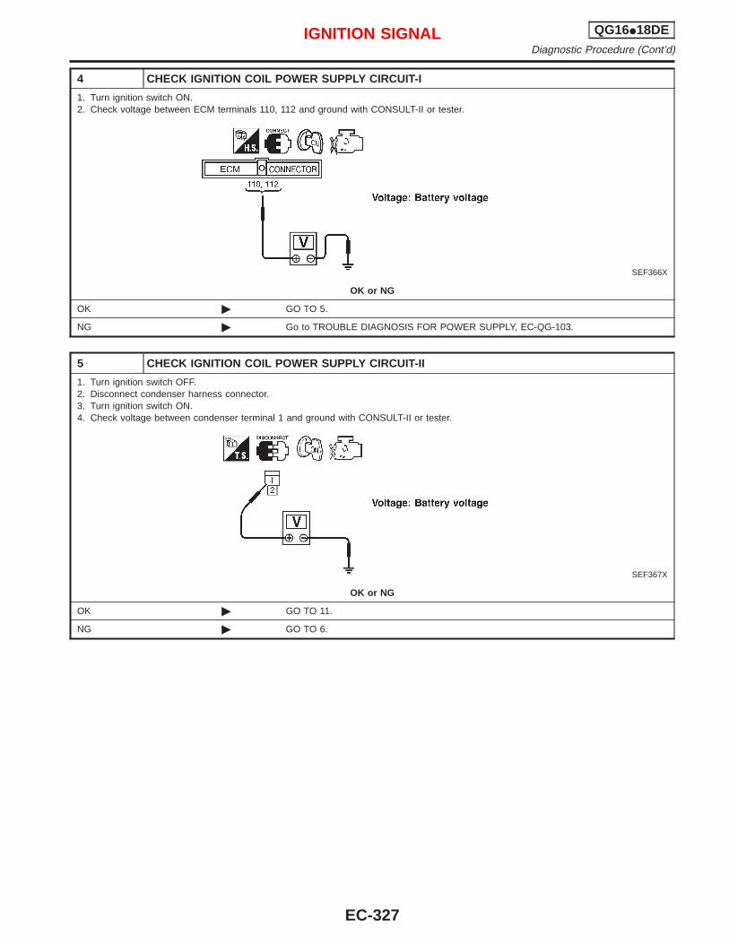
4 CHECK IGNITION COIL POWER SUPPLY CIRCUIT-I
1. Turn ignition switch ON.2. Check voltage between ECM terminals 110, 112 and ground with CONSULT-II or tester.
SEF366X
OK or NG
OK © GO TO 5.
NG © Go to TROUBLE DIAGNOSIS FOR POWER SUPPLY, EC-QG-103.
5 CHECK IGNITION COIL POWER SUPPLY CIRCUIT-II
1. Turn ignition switch OFF.2. Disconnect condenser harness connector.3. Turn ignition switch ON.4. Check voltage between condenser terminal 1 and ground with CONSULT-II or tester.
SEF367X
OK or NG
OK © GO TO 11.
NG © GO TO 6.
IGNITION SIGNAL QG16I18DEDiagnostic Procedure (Cont’d)
EC-327
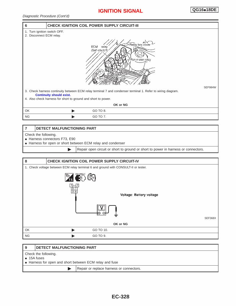
6 CHECK IGNITION COIL POWER SUPPLY CIRCUIT-III
1. Turn ignition switch OFF.2. Disconnect ECM relay.
SEF984W3. Check harness continuity between ECM relay terminal 7 and condenser terminal 1. Refer to wiring diagram.
Continuity should exist.4. Also check harness for short to ground and short to power.
OK or NG
OK © GO TO 8.
NG © GO TO 7.
7 DETECT MALFUNCTIONING PART
Check the following.I Harness connectors F73, E90I Harness for open or short between ECM relay and condenser
© Repair open circuit or short to ground or short to power in harness or connectors.
8 CHECK IGNITION COIL POWER SUPPLY CIRCUIT-IV
1. Check voltage between ECM relay terminal 6 and ground with CONSULT-II or tester.
SEF368X
OK or NG
OK © GO TO 10.
NG © GO TO 9.
9 DETECT MALFUNCTIONING PART
Check the following.I 15A fusesI Harness for open and short between ECM relay and fuse
© Repair or replace harness or connectors.
IGNITION SIGNAL QG16I18DEDiagnostic Procedure (Cont’d)
EC-328
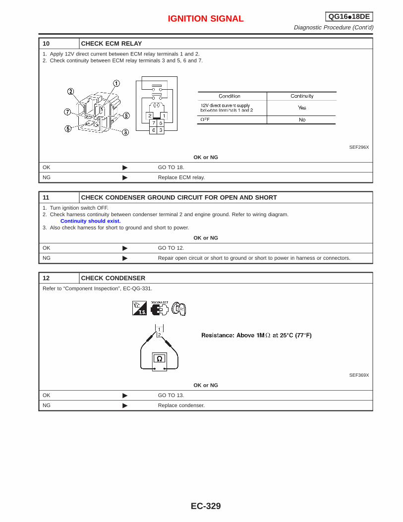
10 CHECK ECM RELAY
1. Apply 12V direct current between ECM relay terminals 1 and 2.2. Check continuity between ECM relay terminals 3 and 5, 6 and 7.
SEF296X
OK or NG
OK © GO TO 18.
NG © Replace ECM relay.
11 CHECK CONDENSER GROUND CIRCUIT FOR OPEN AND SHORT
1. Turn ignition switch OFF.2. Check harness continuity between condenser terminal 2 and engine ground. Refer to wiring diagram.
Continuity should exist.3. Also check harness for short to ground and short to power.
OK or NG
OK © GO TO 12.
NG © Repair open circuit or short to ground or short to power in harness or connectors.
12 CHECK CONDENSER
Refer to “Component Inspection”, EC-QG-331.
SEF369X
OK or NG
OK © GO TO 13.
NG © Replace condenser.
IGNITION SIGNAL QG16I18DEDiagnostic Procedure (Cont’d)
EC-329
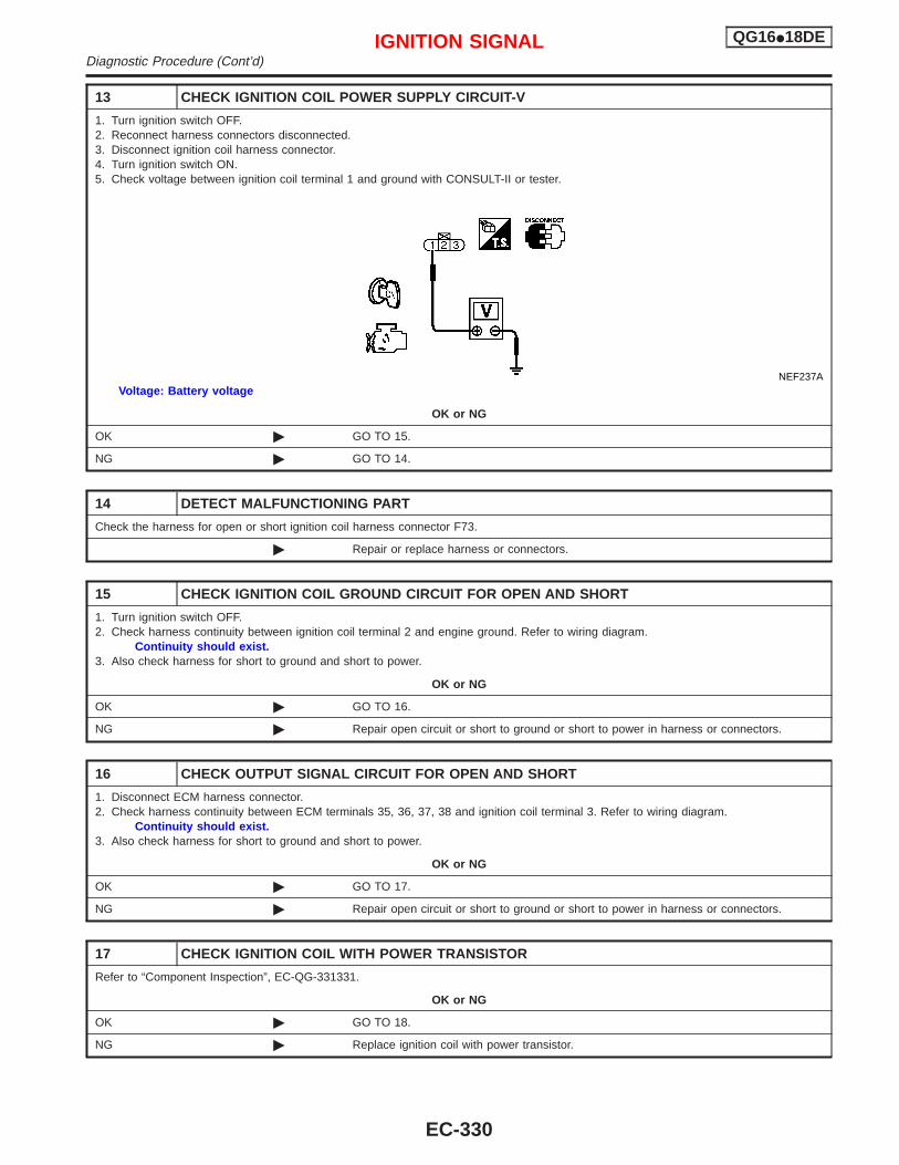
13 CHECK IGNITION COIL POWER SUPPLY CIRCUIT-V
1. Turn ignition switch OFF.2. Reconnect harness connectors disconnected.3. Disconnect ignition coil harness connector.4. Turn ignition switch ON.5. Check voltage between ignition coil terminal 1 and ground with CONSULT-II or tester.
NEF237AVoltage: Battery voltage
OK or NG
OK © GO TO 15.
NG © GO TO 14.
14 DETECT MALFUNCTIONING PART
Check the harness for open or short ignition coil harness connector F73.
© Repair or replace harness or connectors.
15 CHECK IGNITION COIL GROUND CIRCUIT FOR OPEN AND SHORT
1. Turn ignition switch OFF.2. Check harness continuity between ignition coil terminal 2 and engine ground. Refer to wiring diagram.
Continuity should exist.3. Also check harness for short to ground and short to power.
OK or NG
OK © GO TO 16.
NG © Repair open circuit or short to ground or short to power in harness or connectors.
16 CHECK OUTPUT SIGNAL CIRCUIT FOR OPEN AND SHORT
1. Disconnect ECM harness connector.2. Check harness continuity between ECM terminals 35, 36, 37, 38 and ignition coil terminal 3. Refer to wiring diagram.
Continuity should exist.3. Also check harness for short to ground and short to power.
OK or NG
OK © GO TO 17.
NG © Repair open circuit or short to ground or short to power in harness or connectors.
17 CHECK IGNITION COIL WITH POWER TRANSISTOR
Refer to “Component Inspection”, EC-QG-331331.
OK or NG
OK © GO TO 18.
NG © Replace ignition coil with power transistor.
IGNITION SIGNAL QG16I18DEDiagnostic Procedure (Cont’d)
EC-330
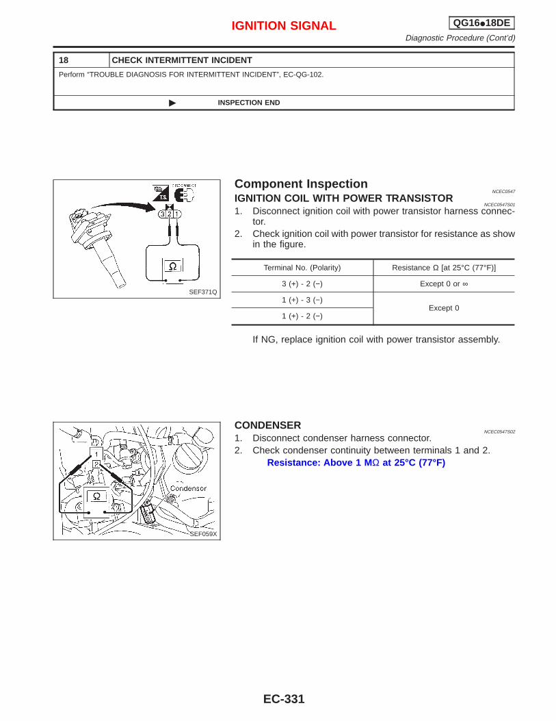
18 CHECK INTERMITTENT INCIDENT
Perform “TROUBLE DIAGNOSIS FOR INTERMITTENT INCIDENT”, EC-QG-102.
© INSPECTION END
Component InspectionNCEC0547
IGNITION COIL WITH POWER TRANSISTORNCEC0547S01
1. Disconnect ignition coil with power transistor harness connec-tor.
2. Check ignition coil with power transistor for resistance as showin the figure.
Terminal No. (Polarity) Resistance Ω [at 25°C (77°F)]
3 (+) - 2 (−) Except 0 or ∞
1 (+) - 3 (−)Except 0
1 (+) - 2 (−)
If NG, replace ignition coil with power transistor assembly.
CONDENSERNCEC0547S02
1. Disconnect condenser harness connector.2. Check condenser continuity between terminals 1 and 2.
Resistance: Above 1 M Ω at 25°C (77°F)
SEF371Q
SEF059X
IGNITION SIGNAL QG16I18DEDiagnostic Procedure (Cont’d)
EC-331
CONSULT-II Reference Value in Data MonitorMode
NCEC0441
Specification data are reference values.
MONITOR ITEM CONDITION SPECIFICATION
START SIGNAL I Ignition switch: ON , START , ON OFF , ON , OFF
ECM Terminals and Reference ValueNCEC0442
Specification data are reference values and are measured between each terminal and ground.CAUTION:Do not use ECM ground terminals when measuring input/output voltage. Doing so may result in dam-age to the ECM’s transistor. Use a ground other than ECM terminals, such as the ground.
TERMI-NALNO.
WIRECOLOR
ITEM CONDITION DATA (DC Voltage)
41 B/Y Start signal[Ignition switch “ON”] Approximately 0V
[Ignition switch “START”] 9 - 12V
START SIGNAL QG16I18DECONSULT-II Reference Value in Data Monitor Mode
EC-332
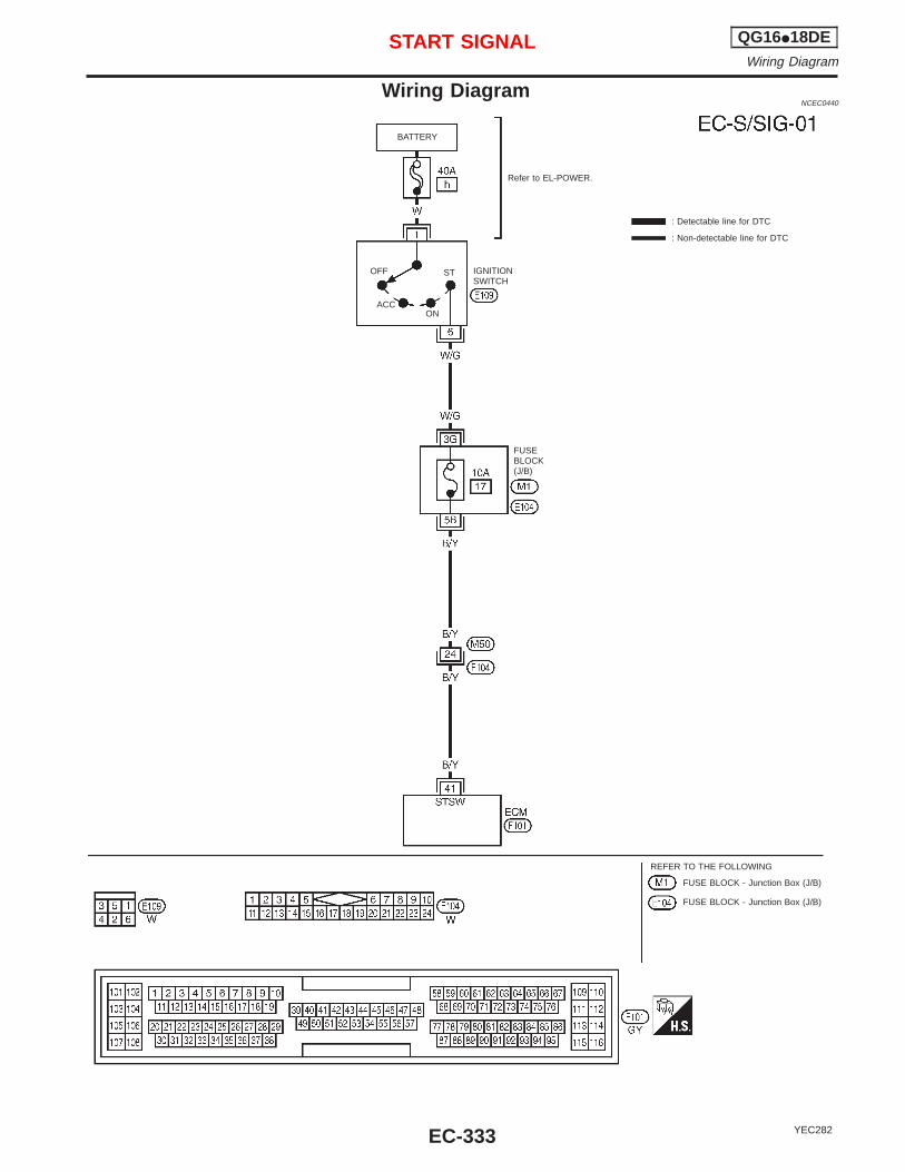
Wiring DiagramNCEC0440
YEC282
BATTERY
Refer to EL-POWER.
: Detectable line for DTC
: Non-detectable line for DTC
FUSEBLOCK(J/B)
IGNITIONSWITCH
REFER TO THE FOLLOWING
FUSE BLOCK - Junction Box (J/B)
FUSE BLOCK - Junction Box (J/B)
OFF
ACCON
ST
START SIGNAL QG16I18DEWiring Diagram
EC-333
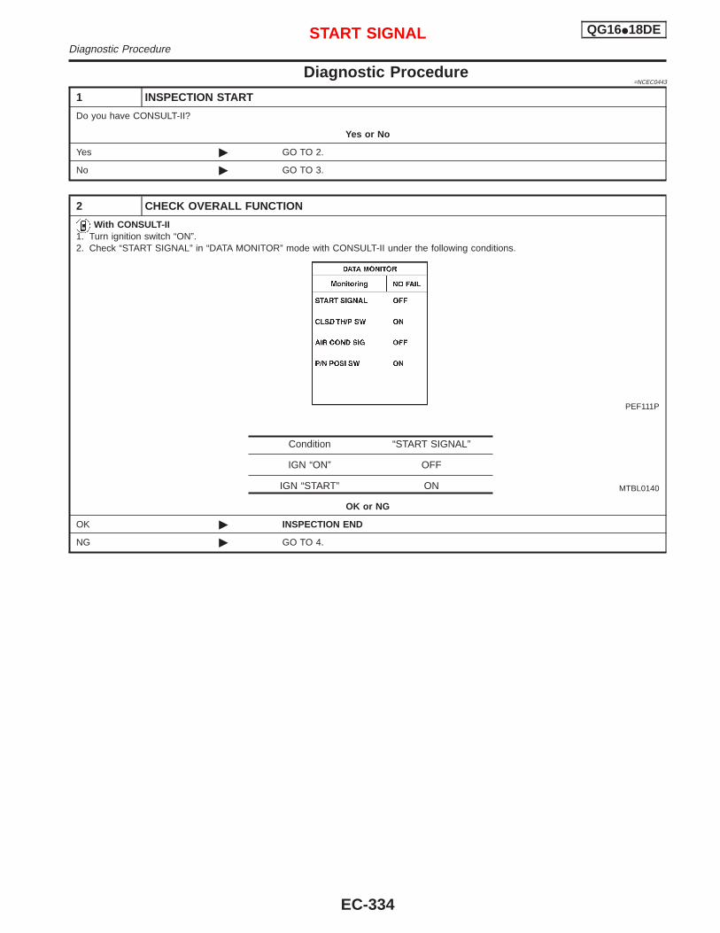
Diagnostic Procedure=NCEC0443
1 INSPECTION START
Do you have CONSULT-II?
Yes or No
Yes © GO TO 2.
No © GO TO 3.
2 CHECK OVERALL FUNCTION
With CONSULT-II1. Turn ignition switch “ON”.2. Check “START SIGNAL” in “DATA MONITOR” mode with CONSULT-II under the following conditions.
PEF111P
MTBL0140
OK or NG
OK © INSPECTION END
NG © GO TO 4.
Condition “START SIGNAL”
IGN “ON” OFF
IGN “START” ON
START SIGNAL QG16I18DEDiagnostic Procedure
EC-334
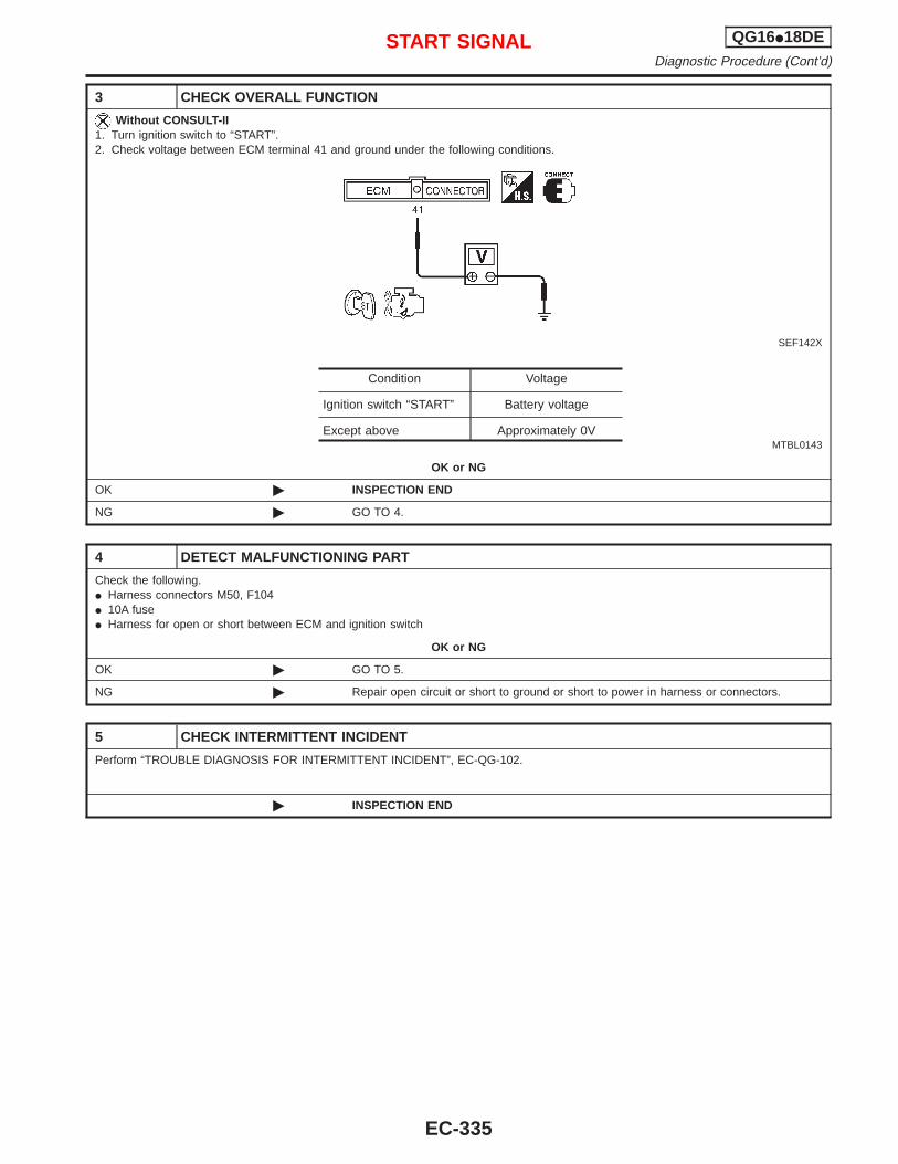
3 CHECK OVERALL FUNCTION
Without CONSULT-II1. Turn ignition switch to “START”.2. Check voltage between ECM terminal 41 and ground under the following conditions.
SEF142X
MTBL0143
OK or NG
OK © INSPECTION END
NG © GO TO 4.
4 DETECT MALFUNCTIONING PART
Check the following.I Harness connectors M50, F104I 10A fuseI Harness for open or short between ECM and ignition switch
OK or NG
OK © GO TO 5.
NG © Repair open circuit or short to ground or short to power in harness or connectors.
5 CHECK INTERMITTENT INCIDENT
Perform “TROUBLE DIAGNOSIS FOR INTERMITTENT INCIDENT”, EC-QG-102.
© INSPECTION END
Condition Voltage
Ignition switch “START” Battery voltage
Except above Approximately 0V
START SIGNAL QG16I18DEDiagnostic Procedure (Cont’d)
EC-335
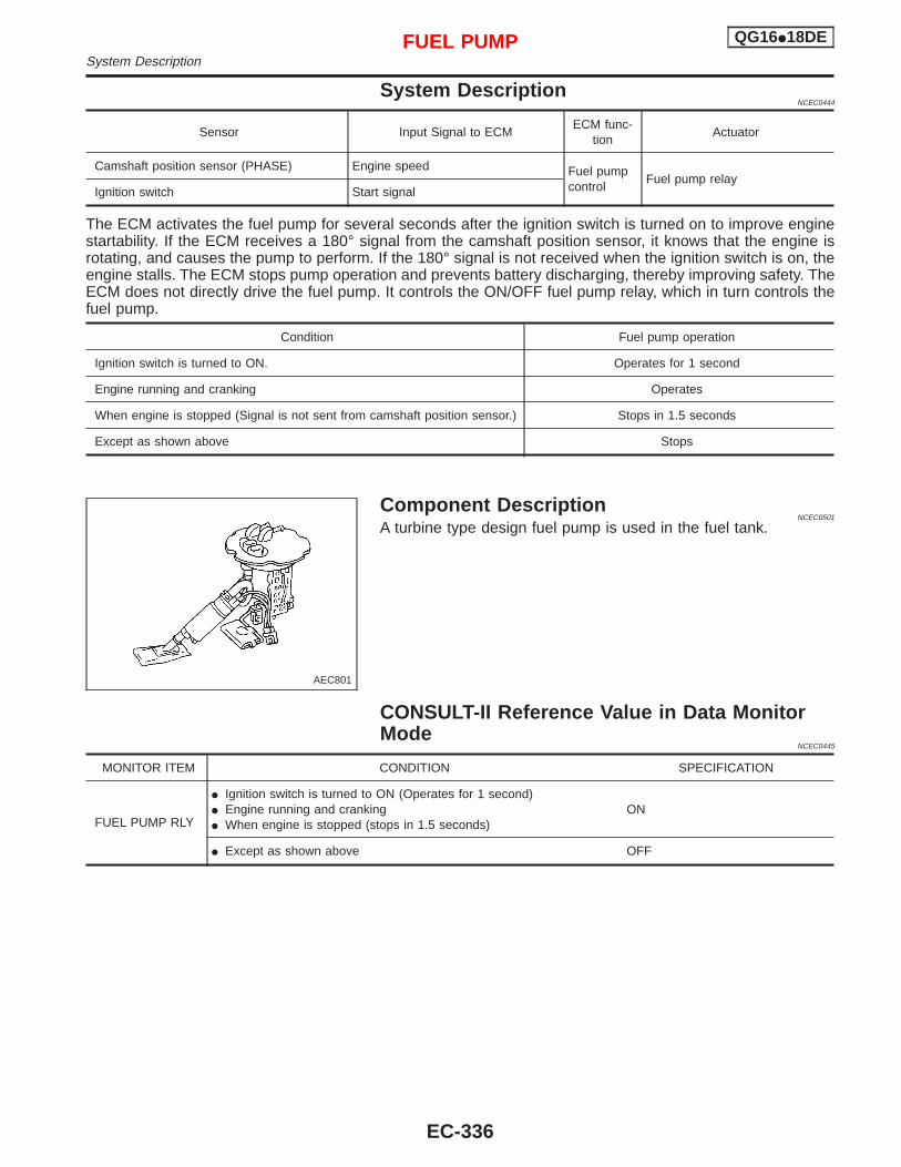
System DescriptionNCEC0444
Sensor Input Signal to ECMECM func-
tionActuator
Camshaft position sensor (PHASE) Engine speed Fuel pumpcontrol
Fuel pump relayIgnition switch Start signal
The ECM activates the fuel pump for several seconds after the ignition switch is turned on to improve enginestartability. If the ECM receives a 180° signal from the camshaft position sensor, it knows that the engine isrotating, and causes the pump to perform. If the 180° signal is not received when the ignition switch is on, theengine stalls. The ECM stops pump operation and prevents battery discharging, thereby improving safety. TheECM does not directly drive the fuel pump. It controls the ON/OFF fuel pump relay, which in turn controls thefuel pump.
Condition Fuel pump operation
Ignition switch is turned to ON. Operates for 1 second
Engine running and cranking Operates
When engine is stopped (Signal is not sent from camshaft position sensor.) Stops in 1.5 seconds
Except as shown above Stops
Component DescriptionNCEC0501
A turbine type design fuel pump is used in the fuel tank.
CONSULT-II Reference Value in Data MonitorMode
NCEC0445
MONITOR ITEM CONDITION SPECIFICATION
FUEL PUMP RLY
I Ignition switch is turned to ON (Operates for 1 second)I Engine running and crankingI When engine is stopped (stops in 1.5 seconds)
ON
I Except as shown above OFF
AEC801
FUEL PUMP QG16I18DESystem Description
EC-336
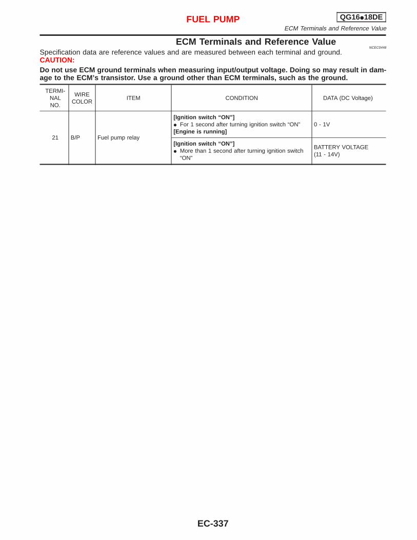
ECM Terminals and Reference ValueNCEC0446
Specification data are reference values and are measured between each terminal and ground.CAUTION:Do not use ECM ground terminals when measuring input/output voltage. Doing so may result in dam-age to the ECM’s transistor. Use a ground other than ECM terminals, such as the ground.
TERMI-NALNO.
WIRECOLOR
ITEM CONDITION DATA (DC Voltage)
21 B/P Fuel pump relay
[Ignition switch “ON”]I For 1 second after turning ignition switch “ON”[Engine is running]
0 - 1V
[Ignition switch “ON”]I More than 1 second after turning ignition switch
“ON”
BATTERY VOLTAGE(11 - 14V)
FUEL PUMP QG16I18DEECM Terminals and Reference Value
EC-337
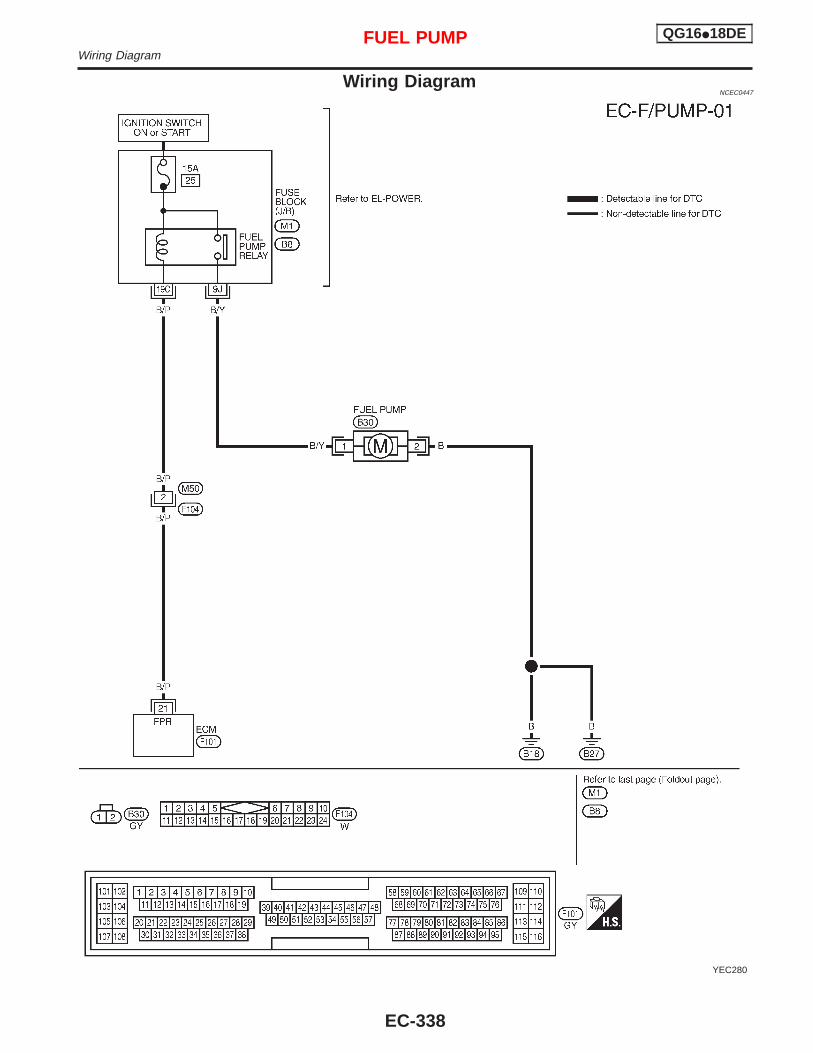
Wiring DiagramNCEC0447
YEC280
FUEL PUMP QG16I18DEWiring Diagram
EC-338
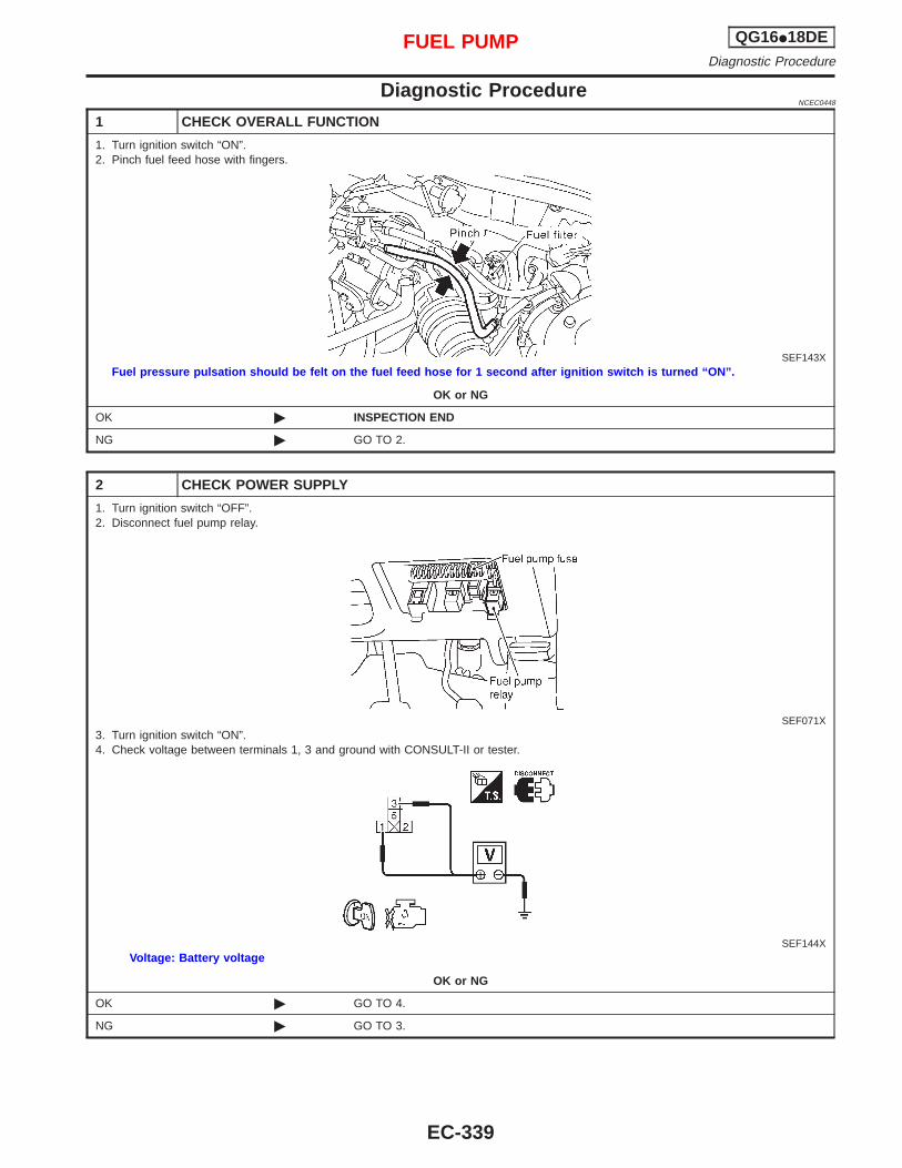
Diagnostic ProcedureNCEC0448
1 CHECK OVERALL FUNCTION
1. Turn ignition switch “ON”.2. Pinch fuel feed hose with fingers.
SEF143XFuel pressure pulsation should be felt on the fuel feed hose for 1 second after ignition switch is turned “ON”.
OK or NG
OK © INSPECTION END
NG © GO TO 2.
2 CHECK POWER SUPPLY
1. Turn ignition switch “OFF”.2. Disconnect fuel pump relay.
SEF071X3. Turn ignition switch “ON”.4. Check voltage between terminals 1, 3 and ground with CONSULT-II or tester.
SEF144XVoltage: Battery voltage
OK or NG
OK © GO TO 4.
NG © GO TO 3.
FUEL PUMP QG16I18DEDiagnostic Procedure
EC-339
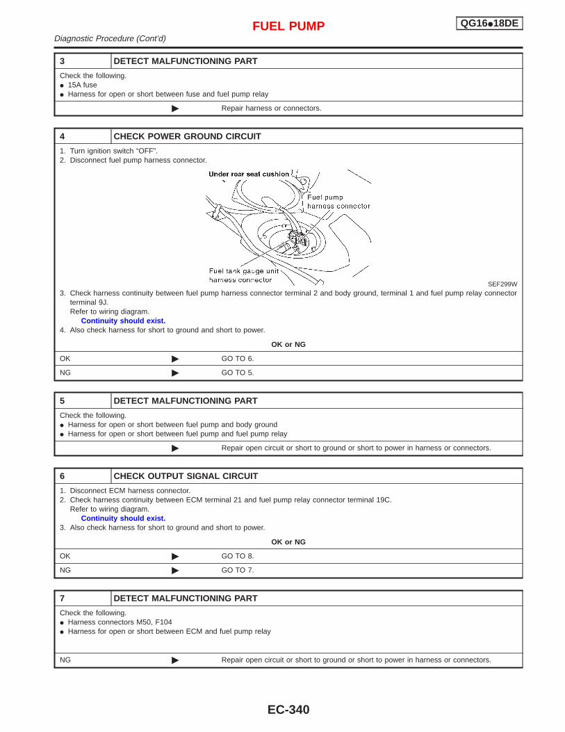
3 DETECT MALFUNCTIONING PART
Check the following.I 15A fuseI Harness for open or short between fuse and fuel pump relay
© Repair harness or connectors.
4 CHECK POWER GROUND CIRCUIT
1. Turn ignition switch “OFF”.2. Disconnect fuel pump harness connector.
SEF299W3. Check harness continuity between fuel pump harness connector terminal 2 and body ground, terminal 1 and fuel pump relay connector
terminal 9J.Refer to wiring diagram.
Continuity should exist.4. Also check harness for short to ground and short to power.
OK or NG
OK © GO TO 6.
NG © GO TO 5.
5 DETECT MALFUNCTIONING PART
Check the following.I Harness for open or short between fuel pump and body groundI Harness for open or short between fuel pump and fuel pump relay
© Repair open circuit or short to ground or short to power in harness or connectors.
6 CHECK OUTPUT SIGNAL CIRCUIT
1. Disconnect ECM harness connector.2. Check harness continuity between ECM terminal 21 and fuel pump relay connector terminal 19C.
Refer to wiring diagram.Continuity should exist.
3. Also check harness for short to ground and short to power.
OK or NG
OK © GO TO 8.
NG © GO TO 7.
7 DETECT MALFUNCTIONING PART
Check the following.I Harness connectors M50, F104I Harness for open or short between ECM and fuel pump relay
NG © Repair open circuit or short to ground or short to power in harness or connectors.
FUEL PUMP QG16I18DEDiagnostic Procedure (Cont’d)
EC-340
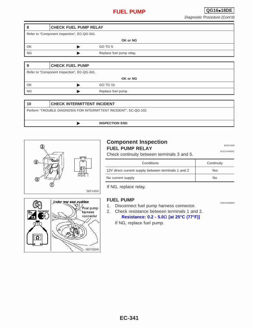
8 CHECK FUEL PUMP RELAY
Refer to “Component Inspection”, EC-QG-341.
OK or NG
OK © GO TO 9.
NG © Replace fuel pump relay.
9 CHECK FUEL PUMP
Refer to “Component Inspection”, EC-QG-341.
OK or NG
OK © GO TO 10.
NG © Replace fuel pump.
10 CHECK INTERMITTENT INCIDENT
Perform “TROUBLE DIAGNOSIS FOR INTERMITTENT INCIDENT”, EC-QG-102.
© INSPECTION END
Component InspectionNCEC0449
FUEL PUMP RELAYNCEC0449S01
Check continuity between terminals 3 and 5.
Conditions Continuity
12V direct current supply between terminals 1 and 2 Yes
No current supply No
If NG, replace relay.
FUEL PUMPNCEC0449S02
1. Disconnect fuel pump harness connector.2. Check resistance between terminals 1 and 2.
Resistance: 0.2 - 5.0 Ω [at 25°C (77°F)]If NG, replace fuel pump.
SEF145X
SEF326W
FUEL PUMP QG16I18DEDiagnostic Procedure (Cont’d)
EC-341
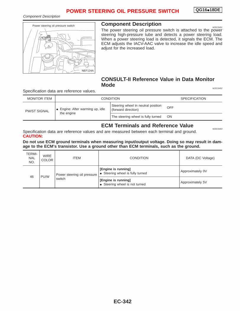
Component DescriptionNCEC0451
The power steering oil pressure switch is attached to the powersteering high-pressure tube and detects a power steering load.When a power steering load is detected, it signals the ECM. TheECM adjusts the IACV-AAC valve to increase the idle speed andadjust for the increased load.
CONSULT-II Reference Value in Data MonitorMode
NCEC0452
Specification data are reference values.
MONITOR ITEM CONDITION SPECIFICATION
PW/ST SIGNALI Engine: After warming up, idle
the engine
Steering wheel in neutral position(forward direction)
OFF
The steering wheel is fully turned ON
ECM Terminals and Reference ValueNCEC0453
Specification data are reference values and are measured between each terminal and ground.CAUTION:Do not use ECM ground terminals when measuring input/output voltage. Doing so may result in dam-age to the ECM’s transistor. Use a ground other than ECM terminals, such as the ground.
TERMI-NALNO.
WIRECOLOR
ITEM CONDITION DATA (DC Voltage)
46 PU/WPower steering oil pressureswitch
[Engine is running]I Steering wheel is fully turned
Approximately 0V
[Engine is running]I Steering wheel is not turned
Approximately 5V
NEF124A
Power steering oil pressure switch
POWER STEERING OIL PRESSURE SWITCH QG16I18DEComponent Description
EC-342
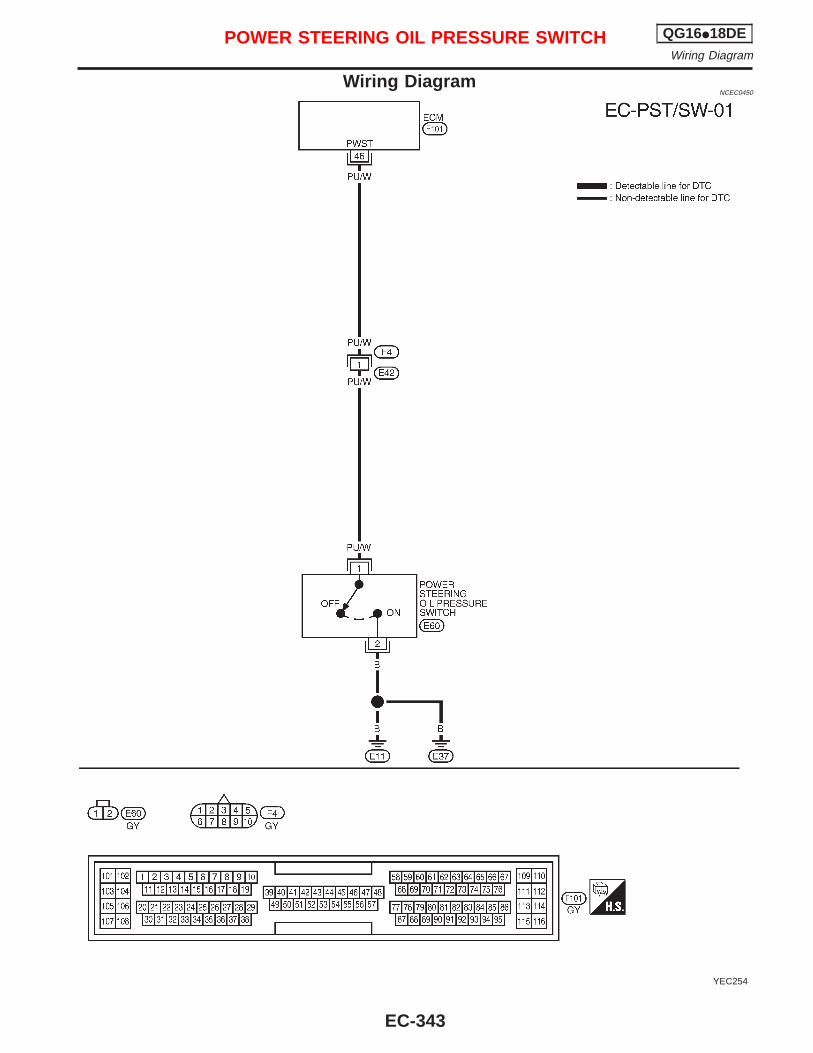
Wiring DiagramNCEC0450
YEC254
POWER STEERING OIL PRESSURE SWITCH QG16I18DEWiring Diagram
EC-343
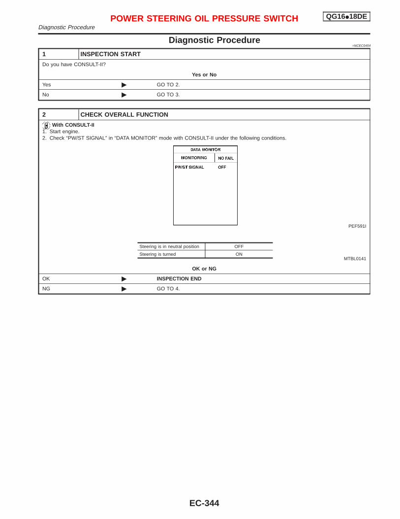
Diagnostic Procedure=NCEC0454
1 INSPECTION START
Do you have CONSULT-II?
Yes or No
Yes © GO TO 2.
No © GO TO 3.
2 CHECK OVERALL FUNCTION
With CONSULT-II1. Start engine.2. Check “PW/ST SIGNAL” in “DATA MONITOR” mode with CONSULT-II under the following conditions.
PEF591I
MTBL0141
OK or NG
OK © INSPECTION END
NG © GO TO 4.
Steering is in neutral position OFF
Steering is turned ON
POWER STEERING OIL PRESSURE SWITCH QG16I18DEDiagnostic Procedure
EC-344
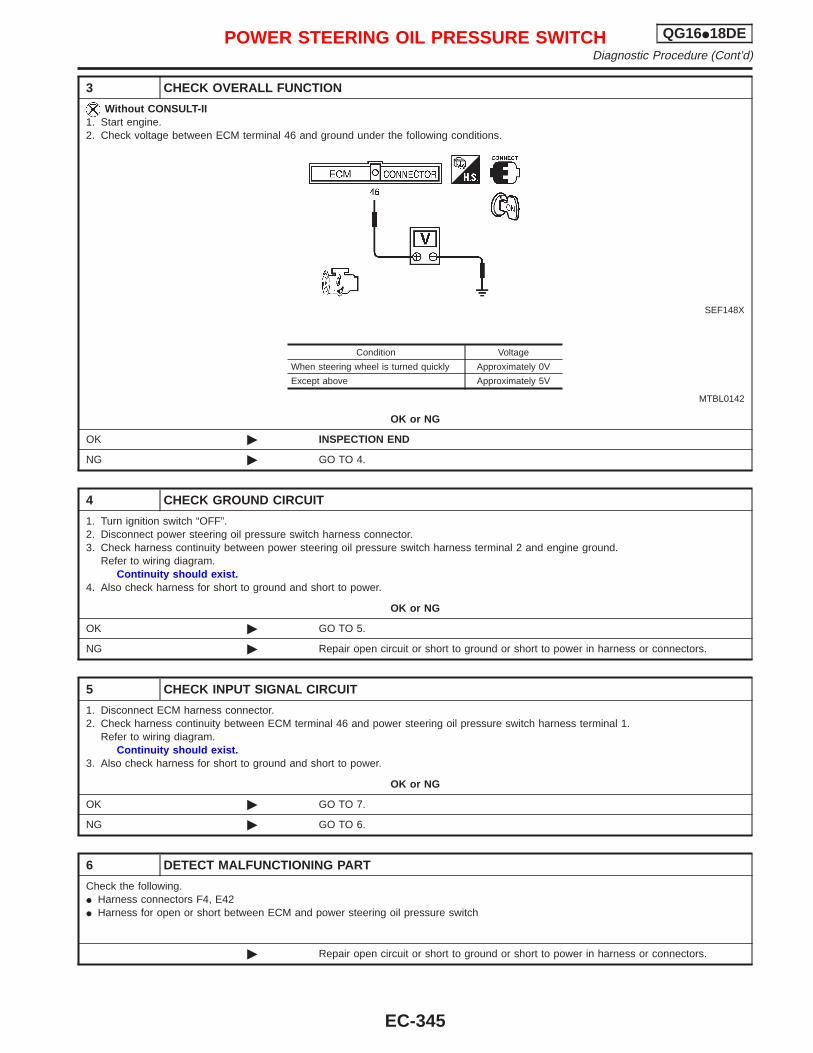
3 CHECK OVERALL FUNCTION
Without CONSULT-II1. Start engine.2. Check voltage between ECM terminal 46 and ground under the following conditions.
SEF148X
MTBL0142
OK or NG
OK © INSPECTION END
NG © GO TO 4.
4 CHECK GROUND CIRCUIT
1. Turn ignition switch “OFF”.2. Disconnect power steering oil pressure switch harness connector.3. Check harness continuity between power steering oil pressure switch harness terminal 2 and engine ground.
Refer to wiring diagram.Continuity should exist.
4. Also check harness for short to ground and short to power.
OK or NG
OK © GO TO 5.
NG © Repair open circuit or short to ground or short to power in harness or connectors.
5 CHECK INPUT SIGNAL CIRCUIT
1. Disconnect ECM harness connector.2. Check harness continuity between ECM terminal 46 and power steering oil pressure switch harness terminal 1.
Refer to wiring diagram.Continuity should exist.
3. Also check harness for short to ground and short to power.
OK or NG
OK © GO TO 7.
NG © GO TO 6.
6 DETECT MALFUNCTIONING PART
Check the following.I Harness connectors F4, E42I Harness for open or short between ECM and power steering oil pressure switch
© Repair open circuit or short to ground or short to power in harness or connectors.
Condition Voltage
When steering wheel is turned quickly Approximately 0V
Except above Approximately 5V
POWER STEERING OIL PRESSURE SWITCH QG16I18DEDiagnostic Procedure (Cont’d)
EC-345
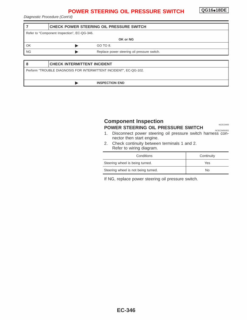
7 CHECK POWER STEERING OIL PRESSURE SWITCH
Refer to “Component Inspection”, EC-QG-346.
OK or NG
OK © GO TO 8.
NG © Replace power steering oil pressure switch.
8 CHECK INTERMITTENT INCIDENT
Perform “TROUBLE DIAGNOSIS FOR INTERMITTENT INCIDENT”, EC-QG-102.
© INSPECTION END
Component InspectionNCEC0455
POWER STEERING OIL PRESSURE SWITCHNCEC0455S01
1. Disconnect power steering oil pressure switch harness con-nector then start engine.
2. Check continuity between terminals 1 and 2.Refer to wiring diagram.
Conditions Continuity
Steering wheel is being turned. Yes
Steering wheel is not being turned. No
If NG, replace power steering oil pressure switch.
POWER STEERING OIL PRESSURE SWITCH QG16I18DEDiagnostic Procedure (Cont’d)
EC-346
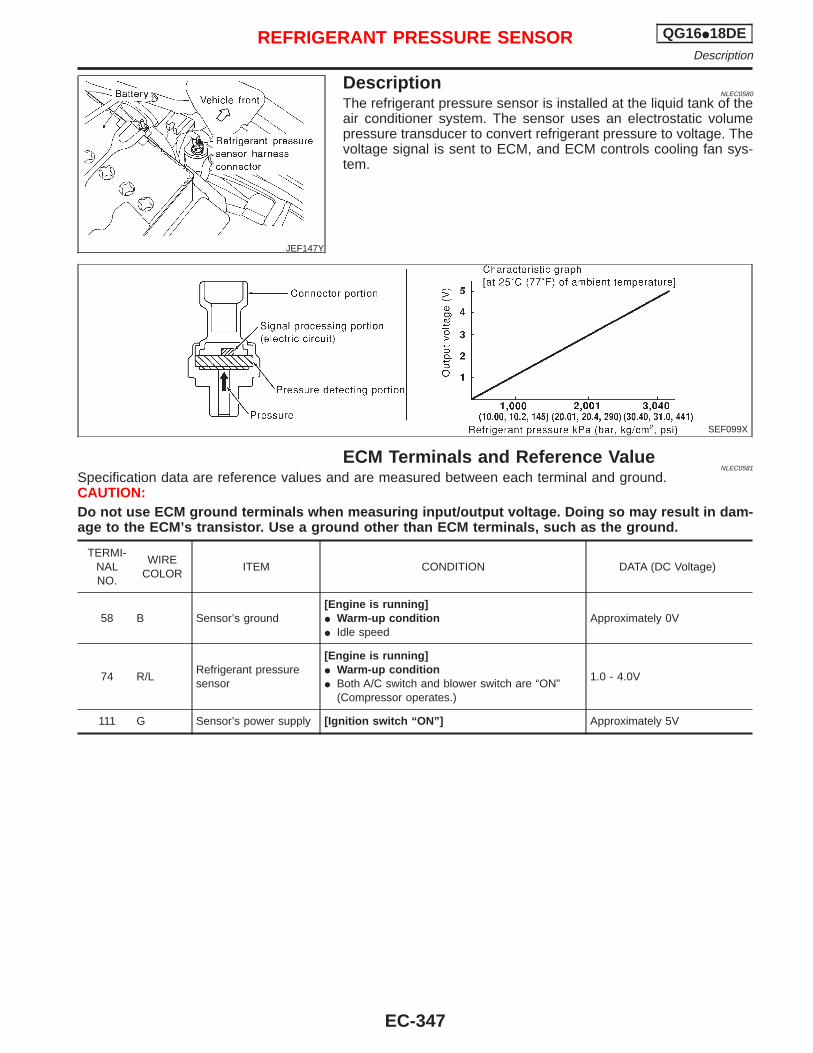
JEF147Y
DescriptionNLEC0580
The refrigerant pressure sensor is installed at the liquid tank of theair conditioner system. The sensor uses an electrostatic volumepressure transducer to convert refrigerant pressure to voltage. Thevoltage signal is sent to ECM, and ECM controls cooling fan sys-tem.
SEF099X
ECM Terminals and Reference ValueNLEC0581
Specification data are reference values and are measured between each terminal and ground.CAUTION:Do not use ECM ground terminals when measuring input/output voltage. Doing so may result in dam-age to the ECM’s transistor. Use a ground other than ECM terminals, such as the ground.
TERMI-NALNO.
WIRECOLOR
ITEM CONDITION DATA (DC Voltage)
58 B Sensor’s ground[Engine is running]I Warm-up conditionI Idle speed
Approximately 0V
74 R/LRefrigerant pressuresensor
[Engine is running]I Warm-up conditionI Both A/C switch and blower switch are “ON”
(Compressor operates.)
1.0 - 4.0V
111 G Sensor’s power supply [Ignition switch “ON”] Approximately 5V
REFRIGERANT PRESSURE SENSOR QG16I18DEDescription
EC-347
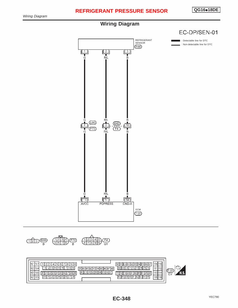
Wiring Diagram
YEC790
: Detectable line for DTC
: Non-detectable line for DTC
REFRIGERANTSENSOR
ECM
REFRIGERANT PRESSURE SENSOR QG16I18DEWiring Diagram
EC-348
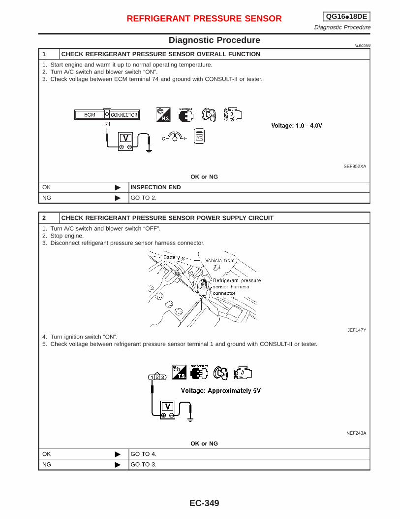
Diagnostic ProcedureNLEC0590
1 CHECK REFRIGERANT PRESSURE SENSOR OVERALL FUNCTION
1. Start engine and warm it up to normal operating temperature.2. Turn A/C switch and blower switch “ON”.3. Check voltage between ECM terminal 74 and ground with CONSULT-II or tester.
SEF952XA
OK or NG
OK © INSPECTION END
NG © GO TO 2.
2 CHECK REFRIGERANT PRESSURE SENSOR POWER SUPPLY CIRCUIT
1. Turn A/C switch and blower switch “OFF”.2. Stop engine.3. Disconnect refrigerant pressure sensor harness connector.
JEF147Y
4. Turn ignition switch “ON”.5. Check voltage between refrigerant pressure sensor terminal 1 and ground with CONSULT-II or tester.
NEF243A
OK or NG
OK © GO TO 4.
NG © GO TO 3.
REFRIGERANT PRESSURE SENSOR QG16I18DEDiagnostic Procedure
EC-349
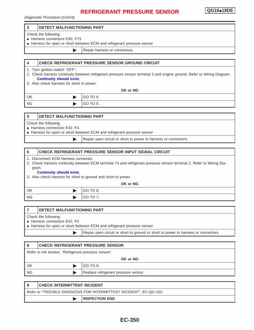
3 DETECT MALFUNCTIONING PART
Check the following.I Harness connectors E90, F73I Harness for open or short between ECM and refrigerant pressure sensor
© Repair harness or connectors.
4 CHECK REFRIGERANT PRESSURE SENSOR GROUND CIRCUIT
1. Turn ignition switch “OFF”.2. Check harness continuity between refrigerant pressure sensor terminal 3 and engine ground. Refer to Wiring Diagram.
Continuity should exist.3. Also check harness for short to power.
OK or NG
OK © GO TO 6.
NG © GO TO 5.
5 DETECT MALFUNCTIONING PART
Check the following.I Harness connectors E42, F4I Harness for open or short between ECM and refrigerant pressure sensor
© Repair open circuit or short to power in harness or connectors.
6 CHECK REFRIGERANT PRESSURE SENSOR INPUT SIGNAL CIRCUIT
1. Disconnect ECM harness connector.2. Check harness continuity between ECM terminal 74 and refrigerant pressure sensor terminal 2. Refer to Wiring Dia-
gram.Continuity should exist.
3. Also check harness for short to ground and short to power.
OK or NG
OK © GO TO 8.
NG © GO TO 7.
7 DETECT MALFUNCTIONING PART
Check the following.I Harness connectors E42, F4I Harness for open or short between ECM and refrigerant pressure sensor
© Repair open circuit or short to ground or short to power in harness or connectors.
8 CHECK REFRIGERANT PRESSURE SENSOR
Refer to HA section, “Refrigerant pressure sensor”.
OK or NG
OK © GO TO 9.
NG © Replace refrigerant pressure sensor.
9 CHECK INTERMITTENT INCIDENT
Refer to “TROUBLE DIAGNOSIS FOR INTERMITTENT INCIDENT”, EC-QG-102.
© INSPECTION END
REFRIGERANT PRESSURE SENSOR QG16I18DEDiagnostic Procedure (Cont’d)
EC-350
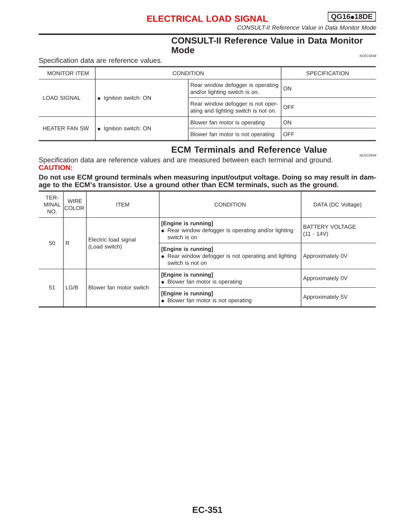
CONSULT-II Reference Value in Data MonitorMode
NCEC0548
Specification data are reference values.
MONITOR ITEM CONDITION SPECIFICATION
LOAD SIGNAL I Ignition switch: ON
Rear window defogger is operatingand/or lighting switch is on.
ON
Rear window defogger is not oper-ating and lighting switch is not on.
OFF
HEATER FAN SW I Ignition switch: ONBlower fan motor is operating ON
Blower fan motor is not operating OFF
ECM Terminals and Reference ValueNCEC0549
Specification data are reference values and are measured between each terminal and ground.CAUTION:Do not use ECM ground terminals when measuring input/output voltage. Doing so may result in dam-age to the ECM’s transistor. Use a ground other than ECM terminals, such as the ground.
TER-MINAL
NO.
WIRECOLOR
ITEM CONDITION DATA (DC Voltage)
50 RElectric load signal(Load switch)
[Engine is running]I Rear window defogger is operating and/or lighting
switch is on
BATTERY VOLTAGE(11 - 14V)
[Engine is running]I Rear window defogger is not operating and lighting
switch is not onApproximately 0V
51 LG/B Blower fan motor switch
[Engine is running]I Blower fan motor is operating
Approximately 0V
[Engine is running]I Blower fan motor is not operating
Approximately 5V
ELECTRICAL LOAD SIGNAL QG16I18DECONSULT-II Reference Value in Data Monitor Mode
EC-351
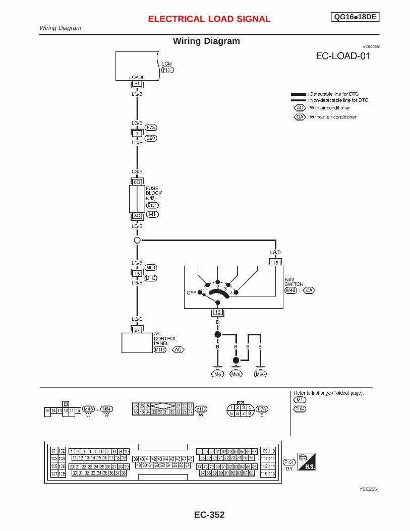
Wiring DiagramNCEC0550
YEC255
ELECTRICAL LOAD SIGNAL QG16I18DEWiring Diagram
EC-352
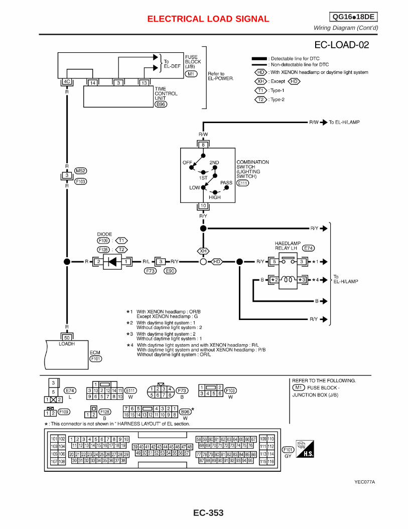
YEC077A
ELECTRICAL LOAD SIGNAL QG16I18DEWiring Diagram (Cont’d)
EC-353
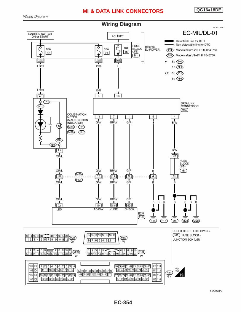
Wiring DiagramNCEC0466
YEC078A
MI & DATA LINK CONNECTORS QG16I18DEWiring Diagram
EC-354
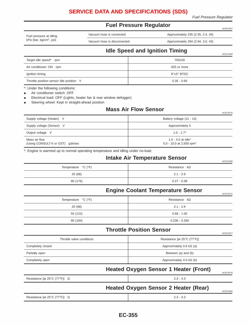
Fuel Pressure RegulatorNCEC0467
Fuel pressure at idlingkPa (bar, kg/cm2, psi)
Vacuum hose is connected Approximately 235 (2.35, 2.4, 34)
Vacuum hose is disconnected Approximately 294 (2.94, 3.0, 43)
Idle Speed and Ignition TimingNCEC0468
Target idle speed* rpm 700±50
Air conditioner: ON rpm 825 or more
Ignition timing 8°±5° BTDC
Throttle position sensor idle position V 0.35 - 0.65
*: Under the following conditions:I Air conditioner switch: OFFI Electrical load: OFF (Lights, heater fan & rear window defogger)I Steering wheel: Kept in straight-ahead position
Mass Air Flow SensorNCEC0470
Supply voltage (Heater) V Battery voltage (11 - 14)
Supply voltage (Sensor) V Approximately 5
Output voltage V 1.0 - 1.7*
Mass air flow(Using CONSULT-II or GST) g⋅m/sec
1.0 - 4.0 at idle*5.0 - 10.0 at 2,500 rpm*
*: Engine is warmed up to normal operating temperature and idling under no-load.
Intake Air Temperature SensorNCEC0480
Temperature °C (°F) Resistance kΩ
20 (68) 2.1 - 2.9
80 (176) 0.27 - 0.38
Engine Coolant Temperature SensorNCEC0471
Temperature °C (°F) Resistance kΩ
20 (68) 2.1 - 2.9
50 (122) 0.68 - 1.00
90 (194) 0.236 - 0.260
Throttle Position SensorNCEC0477
Throttle valve conditions Resistance [at 25°C (77°F)]
Completely closed Approximately 0.6 kΩ (a)
Partially open Between (a) and (b)
Completely open Approximately 4.0 kΩ (b)
Heated Oxygen Sensor 1 Heater (Front)NCEC0478
Resistance [at 25°C (77°F)] Ω 2.3 - 4.3
Heated Oxygen Sensor 2 Heater (Rear)NCEC0483
Resistance [at 25°C (77°F)] Ω 2.3 - 4.3
SERVICE DATA AND SPECIFICATIONS (SDS)Fuel Pressure Regulator
EC-355
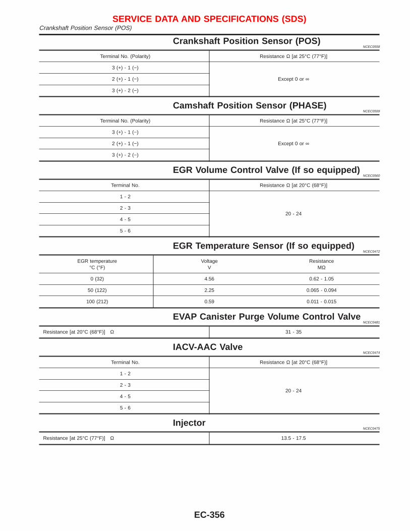
Crankshaft Position Sensor (POS)NCEC0558
Terminal No. (Polarity) Resistance Ω [at 25°C (77°F)]
3 (+) - 1 (−)
Except 0 or ∞2 (+) - 1 (−)
3 (+) - 2 (−)
Camshaft Position Sensor (PHASE)NCEC0559
Terminal No. (Polarity) Resistance Ω [at 25°C (77°F)]
3 (+) - 1 (−)
Except 0 or ∞2 (+) - 1 (−)
3 (+) - 2 (−)
EGR Volume Control Valve (If so equipped)NCEC0560
Terminal No. Resistance Ω [at 20°C (68°F)]
1 - 2
20 - 242 - 3
4 - 5
5 - 6
EGR Temperature Sensor (If so equipped)NCEC0472
EGR temperature°C (°F)
VoltageV
ResistanceMΩ
0 (32) 4.56 0.62 - 1.05
50 (122) 2.25 0.065 - 0.094
100 (212) 0.59 0.011 - 0.015
EVAP Canister Purge Volume Control ValveNCEC0481
Resistance [at 20°C (68°F)] Ω 31 - 35
IACV-AAC ValveNCEC0474
Terminal No. Resistance Ω [at 20°C (68°F)]
1 - 2
20 - 242 - 3
4 - 5
5 - 6
InjectorNCEC0475
Resistance [at 25°C (77°F)] Ω 13.5 - 17.5
SERVICE DATA AND SPECIFICATIONS (SDS)Crankshaft Position Sensor (POS)
EC-356
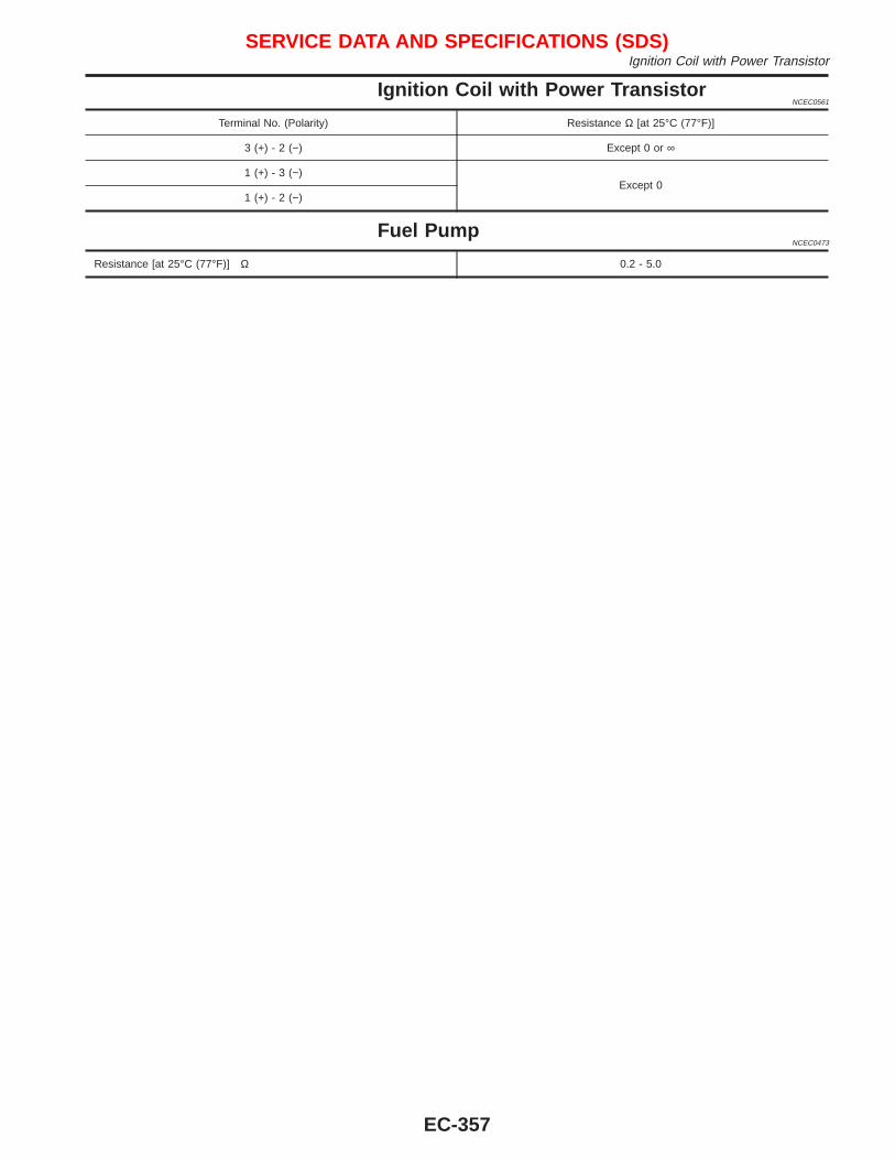
Ignition Coil with Power TransistorNCEC0561
Terminal No. (Polarity) Resistance Ω [at 25°C (77°F)]
3 (+) - 2 (−) Except 0 or ∞
1 (+) - 3 (−)Except 0
1 (+) - 2 (−)
Fuel PumpNCEC0473
Resistance [at 25°C (77°F)] Ω 0.2 - 5.0
SERVICE DATA AND SPECIFICATIONS (SDS)Ignition Coil with Power Transistor
EC-357

NOTE
SERVICE DATA AND SPECIFICATIONS (SDS)
EC-358
Related Documents