Cincinnati, Ohio USA - Glasgow, Scotland UK Diesel Engines for Diesel Engines for Fire Protection Applications Based on NFPA 20 2013 Edition www.clarkefire.com

Engine Application and Start Up Presentation
Oct 24, 2015
Welcome message from author
This document is posted to help you gain knowledge. Please leave a comment to let me know what you think about it! Share it to your friends and learn new things together.
Transcript
Cincinnati, Ohio USA - Glasgow, Scotland UK
Diesel Engines forDiesel Engines for
Fire Protection Applications
Based on NFPA 20 2013 Edition
www.clarkefire.com

Clarke Summary
Clarke assembles engines in two facilities:• Corporate Headquarters in Cincinnati, Ohio, USA
• European Operations in Coatbridge, Scotland, UK
Cincinnati Ohio Coatbridge ScotlandCincinnati, Ohio Coatbridge, Scotland

Clarke Summary
• We have been assembling UL/FM diesel fire pump drivers since 1979.
• We have over 75,000 engines installed globally.
L id f UL/FM di l fi• Largest provider of UL/FM diesel fire pump drivers with around 75% market share.
• Largest range of products available from 37 bhp to 2,376 bhp.

NFPA 20 – Engine Type
• Engines shall be listed for fire pump service.
• Diesel Engines for fire pump drive shall be of the compression ignition type.
S k i i d i l b i• Spark-ignited internal combustion engines shall not be used. (i.e. natural gas, propane or gasoline)

NFPA 20 - Engine Ratings
• Rated at SAE Conditions 25C (77F ) and 91 m (300 ft ) above sea level.
• Engines must have at least a 10% reserve in horsepower and a 4 hour minimum run time. (All UL-FM engine ratings reflect this requirement).
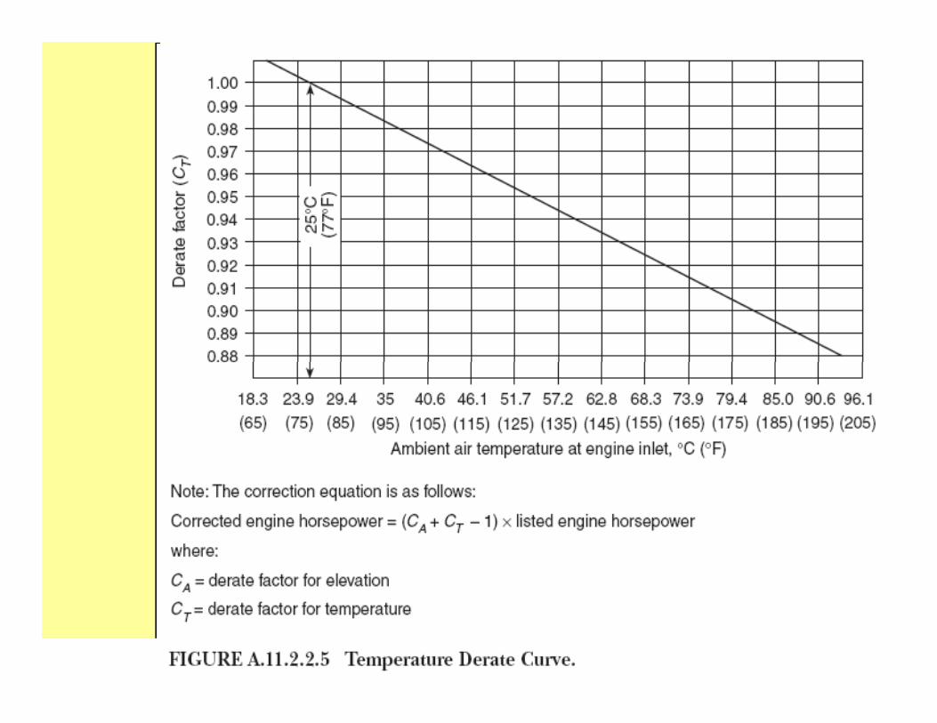
• Engines must be derated for Altitude and Temperature.
– 3% Derate for every 300 m (1000 ft ) above 91 m (300 ft ).
– 1% Derate for every 5.6C (10F ) above 25C (77 F ).

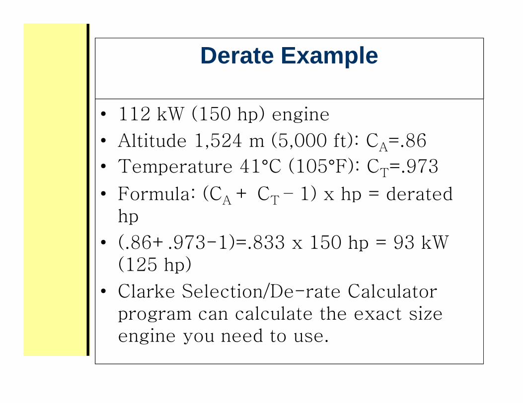
Derate Example
• 112 kW (150 hp) engine
• Altitude 1,524 m (5,000 ft): CA=.86
• Temperature 41°C (105°F): CT=.973
• Formula: (CA + CT – 1) x hp = derated A T php
• (.86+.973-1)=.833 x 150 hp = 93 kW (125 hp)
• Clarke Selection/De-rate Calculator program can calculate the exact size engine you need to use.

Engine Selection/De-rate Calculator

Engine Selection/De-rate Calculator

Engine Selection/De-rate Calculator

NFPA 20 – Instrument & Control
• Engines shall be regulated to have no more the 10% speed difference between shutoff and maximum load. (Defined as droop).
• Engines shall be provided with an over• Engines shall be provided with an over speed shutdown at 20% above rated engine speed with a manual reset. (Only over speed shutdown or a signal from the diesel controller will shut down an engine.)

Over speed Setting VerificationTo verify the engine over speed setting and function without over speeding the engine, follow this procedure:
– Start engine manually from the controller while holding the over speed verification switch in the ‘up’ position. Observe the shutdown RPM.
– Test switch returns to normal position when l dreleased.
– Reset the over speed switch on the engine instrument panel and restart the engine from the controller to verify normal operation.
– EXAMPLE:
Rated engine speed: 2100 rpm Over speed setting: 2520 rpm (120% 2100 rpm) Verification shutdown: 1688 rpm (67% of 2520 rpm)

NFPA 20 – Instrumentation & Control
• Required Gauges:
– Tachometer – indicates RPM’s
– Oil Pressure Gauge
– Coolant Temperature Gauge
– Hour meter – records engine run time
• Additional Gauges:
– Two voltmeters – one for each set of batteries

NFPA 20 – Instrumentation & Control
• The engine instrument panel shall not be used as a junction box or conduit for any AC supply.
• Interconnections between the automatic controller and engine junction box shall becontroller and engine junction box shall be made using stranded wire sized on a continuous-duty basis.
• The DC interconnections between the automatic controller and engine junction box and any AC power supply to the engine shall be routed in separate conduit.

Terminal Interconnect Function
1 Signal from Controller Energize to Run
2 Signal to Controller Engine Running
3 Signal to Controller Over Speed Alarm
4 Signal to Controller Low Oil Pressure Alarm
5 Signal to Controller High Engine Coolant Temp. Alarm
6 Power Supply and Charging Set #1
(7) (Not used)
8 Power Supply and Charging Set #2
9 Cranking Signal from Controller Start System #1
Engine-to-Controller Connections
10 Cranking Signal from Controller Start System #2
11 Common Ground
12 Signal from Controller Energize to Stop
301 Signal to Controller Alternate ECM Alarm (electronic engines)
302 Signal to Controller General Fault Alarm(electronic engines)
312 Signal to Controller Low Engine Coolant Temp. Alarm
Typical Wire Size ****Refer to Controller Manufacturer’s Installation Instructions for minimum size recommendations.1-5, 9, 10, 12, 301, 302, 312 14 Gauge (2 mm) Stranded Wire#6, 8, 11, 10 Gauge (5 mm) Stranded Wire

NFPA 20 – Instrumentation & Control
• Engines with only one starting motor shall include a main battery contactor installed between each battery and the cranking motor for battery isolation.
• The battery contactors shall be listed for the serviceservice.
• Engines with two cranking motors shall have one cranking motor dedicated to each battery.
• Clarke electric starting standard;
• One (1) starter with two (2) start contactors: on JW6H, JX6H, DP6H, DQ6H, DR8H, DS0H, and DT2H units.
• Two (2) starters on JU4H, JU6H units.


NFPA 20 – Instrumentation & Control Electronic Engines
• Engines with an electronic control module (ECM) shall have an alternate ECM wired to produce full power in the event of primary ECM failure.
• There shall be a single ECM Selector Switch, with no off position, to transition from the primary ECM to the alternate ECM.
• A visual indicator shall show when the engine is running with the alternate ECM. (On both the engine panel and on the diesel controller)


Coolant Temp
Overspeed Reset
Bump Enable
Oil Pressure
Overspeed Verification
Bump Toggle (+/-
2 RPM)

NFPA 20 – Instrumentation & Control Electronic Engines
• Any sensor necessary for the function of the ECM shall have a redundant sensor that shall operate automatically in case of failure.
• A signal shall be provided to the diesel controller for fuel injector failure, low fuel pressure and any primary sensor failure.
• The transition from the primary ECM to the alternate ECM shall be accomplished automatically upon failure of the primary ECM
• New 2013: ECM auto switching must happen in either primary or alternate ECM to the opposite.

NFPA 20 – Instrumentation & Control
• New 2013: Means shall be provided for verifying overspeed switch & circuitry shutdown function, testing the operation of the oil pressure, testing the operation of the high engine temperature and testing the operation of h l ithe low engine temperature.
• The engine shall send a signal to the controller, resulting in a visible and common audible alarm on the controller.
• Our new “MECAB” instrument panel for our mechanical engines comply with the 2013 requirements.

Mechanical Engine Control and Alarm Board (MECAB)
Backwards Mode DIP Switch
Overspeed Potentiometer Low Coolant Alarm Verify DIP Switch
High Coolant Alarm Verify DIP Switch
Status LEDPower LED
Temp in range LED

Mechanical Engine Control and Alarm Board (MECAB)
Low and High Coolant Temperature Switch Positions

NFPA 20 – Instrumentation & Control
• Each engine shall be provided with two storage battery units.
• Electrolyte shall be added a minimum of 24 hours prior to the time the engine has to be started.
• At 4.5C (40F ) each battery shall have twice the capacity sufficient to maintain 3 minute attempt-to-start cycle (15 seconds of cranking and 15 seconds of rest in six consecutive cycles).
• Batteries shall be sized on a calculated capacity of 72 hours of stand by power without AC power being available.
NFPA 20 – Instrumentation & Control
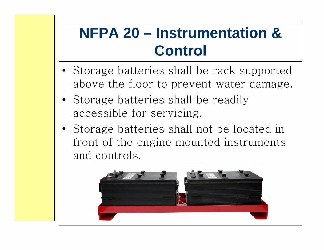
• Storage batteries shall be rack supported above the floor to prevent water damage.
• Storage batteries shall be readily accessible for servicing.
S b i h ll b l d i• Storage batteries shall not be located in front of the engine mounted instruments and controls.

NFPA 20 – Instrumentation & Control
• There should be two means for recharging the storage batteries.• The battery chargers in the diesel controller
is the primary source.
• The alternator on the engine is the• The alternator on the engine is the secondary source.

NFPA 20 – Connecting to Pump
• Engines shall be connected to horizontal shaft pumps by means of a flexible coupling or flexible connecting shaft (drive shaft) listed for this service.
• The flexible coupling shall be directly• The flexible coupling shall be directly attached to the engine flywheel adapter or stub shaft.

NFPA 20 – Torsional Coupling
• New 2013: A torsional vibration damping type coupling shall be used and mounted on the engine side of the driver shaft for all Vertical Turbine pumps unless a torsional analysis is provided andtorsional analysis is provided and accepted by the AHJ to prove it is not necessary.
• For drive systems that include a right angle gear drive, the pump manufacturer shall provide a complete mass elastic system torsional analysis.

NFPA 20 – Engine Cooling
• The engine cooling system shall be of the closed-circuit type.
– Heat exchanger type
– Radiator type

NFPA 20 – Engine Cooling
• Cooling water shall be piped through a threaded rigid pipe from the discharge of the pump to the inlet of the heat exchanger.
• New 2013: Nonmetalic flexible sections• New 2013: Nonmetalic flexible sections shall be allowed between the pump discharge and cooling water provided they have 2 times the fire pump discharge rated pressure & 30 minute fire resistance.
NFPA 20 – Engine Cooling
• The outlet for the wastewater coming from the heat exchanger shall be one size larger then the inlet.
• The wastewater shall be discharged into a visible open waste cone.
• New 2013 – Where pump discharge water is piped back to pump suction, a high cooling temperature signal at 104F (40C) from the inlet of the heat exchanger shall be sent to the controller. Engine will stop during test & alarm during an emergency.

NFPA 20 – Engine Cooling
• Discharge can be piped to a suction reservoir provided a visual flow indicator and temperature indicators are installed.
• Set the temperature indicator at 10F (5.6C) above the Calculated Outlet Temperature found on the Water Temperature Rise Calculator under Engine Selection Tools on our website.
• The Calculated Outlet Temperature calculates the temperature of the water coming out of the Heat Exchanger.

NFPA 20 – Engine Cooling

NFPA 20 – Engine Cooling

NFPA 20 – Engine Cooling

NFPA 20 – Engine Cooling
• Heat exchanger standard equipment. • Sea water or fresh water; sacrificial anode• Engines are shipped with coolant.• Cooling water line (cooling loop) shall have a
manual by-pass.• Cooling water line and by-pass shall include:Cooling water line and by pass shall include:
• indicating manual shutoff valve• approved flushing-type strainer• pressure regulator• automatic valve• second indicating manual valve or check
valve• pressure gauge

Cooling Water Line

Engine Coolant
• Coolant is now included with the engine.
• Water, ethylene glycol, inhibitor coolant mixture. 50% water 50% coolant.
• Coolant to conform to ASTM D6210
– Heat transferHeat transfer
– Corrosion resistance
– Prevents cavitations
– Prevents scale and sludge build up
– Provides freeze and boil over protection
• Pre-mix before installing in engine to prevent premature engine heater failure.

NFPA 20 – Engine Cooling
• Coolant heater is the only AC power on engine; Separate AC junction box required. Do not use controller AC for power supply.
• Add coolant mixture before applying AC power.
• All heaters single voltage; Optional AC voltages available - location specific.
• Engine coolant maintained at 49C (120F)
NFPA 20 – Engine Protection
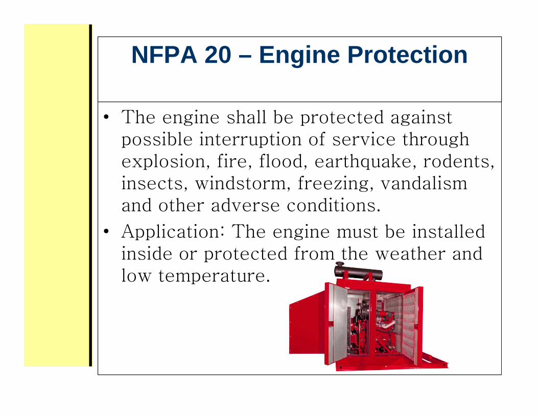
• The engine shall be protected against possible interruption of service through explosion, fire, flood, earthquake, rodents, insects, windstorm, freezing, vandalism and other adverse conditionsand other adverse conditions.
• Application: The engine must be installed inside or protected from the weather and low temperature.

NFPA 20 – Room Requirements
• Floors shall be pitched for adequate drainage of escaping water from critical equipment.
• The pump room shall be provided with a floor drain that will discharge to a frost free location.
• Fire pump rooms enclosing a diesel engine
NFPA 20 – Room Requirements
p p g gpump driver and day tank shall be protected with an automatic sprinkler system installed in accordance with NFPA 13.
• Emergency lighting shall be provided in accordance with NFPA 101. Emergency lights shall not be connected to an engine starting battery
NFPA 20 – Room Requirements
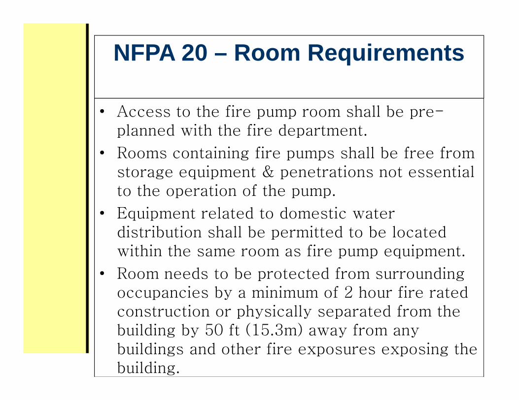
• Access to the fire pump room shall be pre-planned with the fire department.
• Rooms containing fire pumps shall be free from storage equipment & penetrations not essential to the operation of the pump.
NFPA 20 – Room Requirements
• Equipment related to domestic water distribution shall be permitted to be located within the same room as fire pump equipment.
• Room needs to be protected from surrounding occupancies by a minimum of 2 hour fire rated construction or physically separated from the building by 50 ft (15.3m) away from any buildings and other fire exposures exposing the building.

NFPA 20 – Room Requirements
• Fire pump rooms not directly accessible from the outside shall be accessible through an enclosed passageway from an enclosed stairway or exterior exit. The enclosed passageway shall have a
NFPA 20 – Room Requirements
enclosed passageway shall have a minimum 2 hour fire resistance rating.
• New 2013 – Pump room shall be sized to fit all of the components necessary for the operation of the fire pump and there must be clearance between components, the wall and electrical equipment for installation and maintenance.

NFPA 20 – Air Requirements
• The minimum ambient temperature for the pump room is 4.5C (40F ).
– An approved or listed source of heat shall be provided for maintaining the temperature of a pump room or pump house.
• Limit the maximum temperature for the pump room to 49C (120F ) at the air cleaner inlet with the engine running at rated load.

NFPA 20 – Air Requirements
• Inlet louver and ventilating system must:– Maintain 49C (120F ) in the room
– Supply adequate air for engine combustion
– Supply adequate air for ventilating radiated heat; both engine & exhaust system.
• Radiator Cooled Units shall be ducted outdoors in a manner that will prevent recirculation and requires more air for combustion and radiated heat removal.

Installation and Operation Data

Installation and Operation Data


Heat Exchanger Ventilation

Radiator Ventilation

Radiator Ventilation
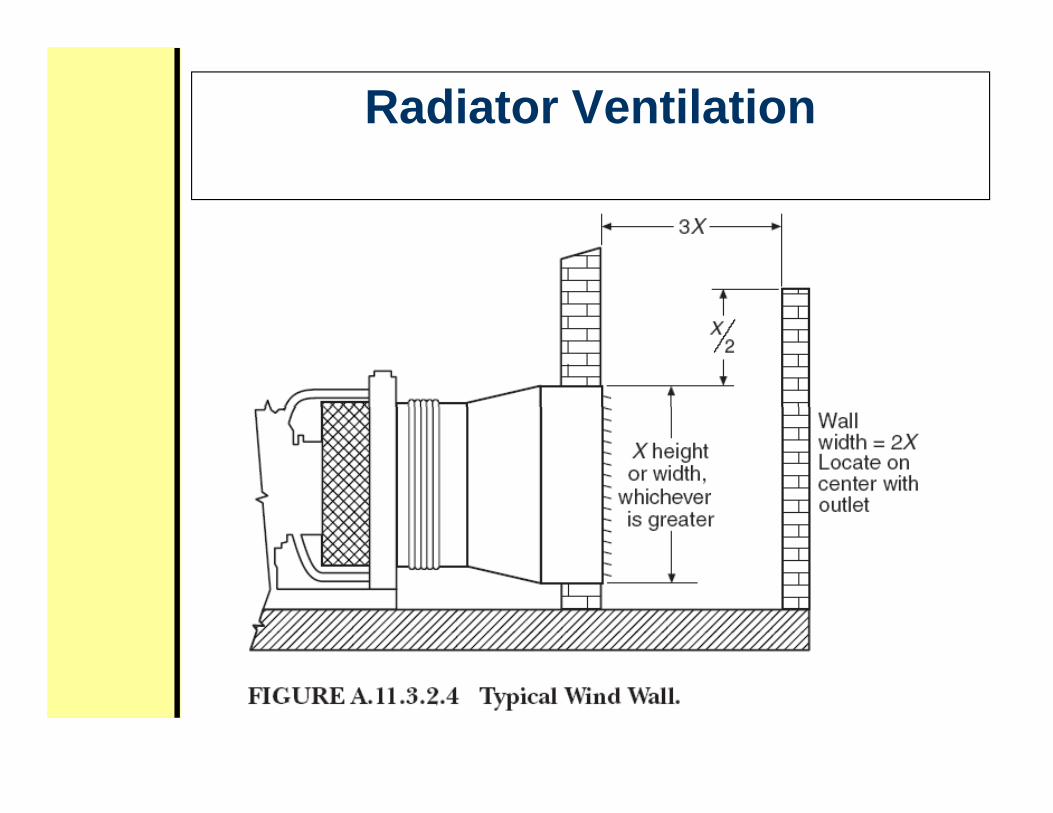
Radiator Ventilation

NFPA 20 – Fuel Tank Arrangement
• The fuel tank is sized for 5.07 liter/kW (1 gal/HP) plus 10% (5% for expansion and 5% for sump).
• The fuel tank shall be reserved exclusively for the fire pump diesel engine.
• There shall be one fuel tank per engine.
• The fuel tank shall be located above ground.
• The fuel tank outlet shall be located so that its opening is no lower than the level of the engine’s fuel transfer pump.

NFPA 20 – Fuel Tank Arrangement
• The static head pressure limits shall not be exceeded when the level of fuel in the tank is at a maximum.
• New 2013: A manual shut off valve shall be provided within the tank fuel supply line locked in the open position. No valves other than the manual fuel shut off are allowed in the fuel supply.
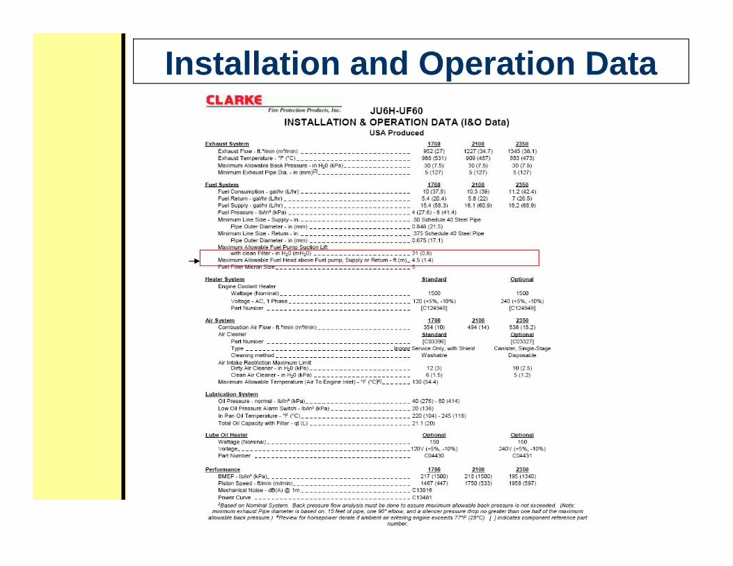
Installation and Operation Data

NFPA 20 – Fuel Tank Arrangement
• In sites where temperatures below 0C(32F ) could be encountered, the fuel tank shall be located in the pump room.
• The fuel storage tanks shall be kept as full as practical at all times but neverfull as practical at all times, but never below 66% of tank capacity. A fuel level indicator shall be provided to activate at the 2/3rds tank level.
• New 2013: Bonding & grounding will be required on all metallic components, piping and equipment in the fuel supply to prevent electrostatic ignitions.

NFPA 20 – Fuel Arrangement
• The diesel engine must use clean #2 diesel.
• #1, blended fuel, or jet fuel have a lower cetane ratings, which reduces the power output by 10% of the engine compared with the listed power.
• Biodiesel and other alternative fuels are not recommended for diesel engines used for fire protection because of the unknown storage life issues.
• A guard, pipe protection, or approved double walled pipe shall be provided for all exposed fuel lines.

NFPA 20 – Fuel Arrangement
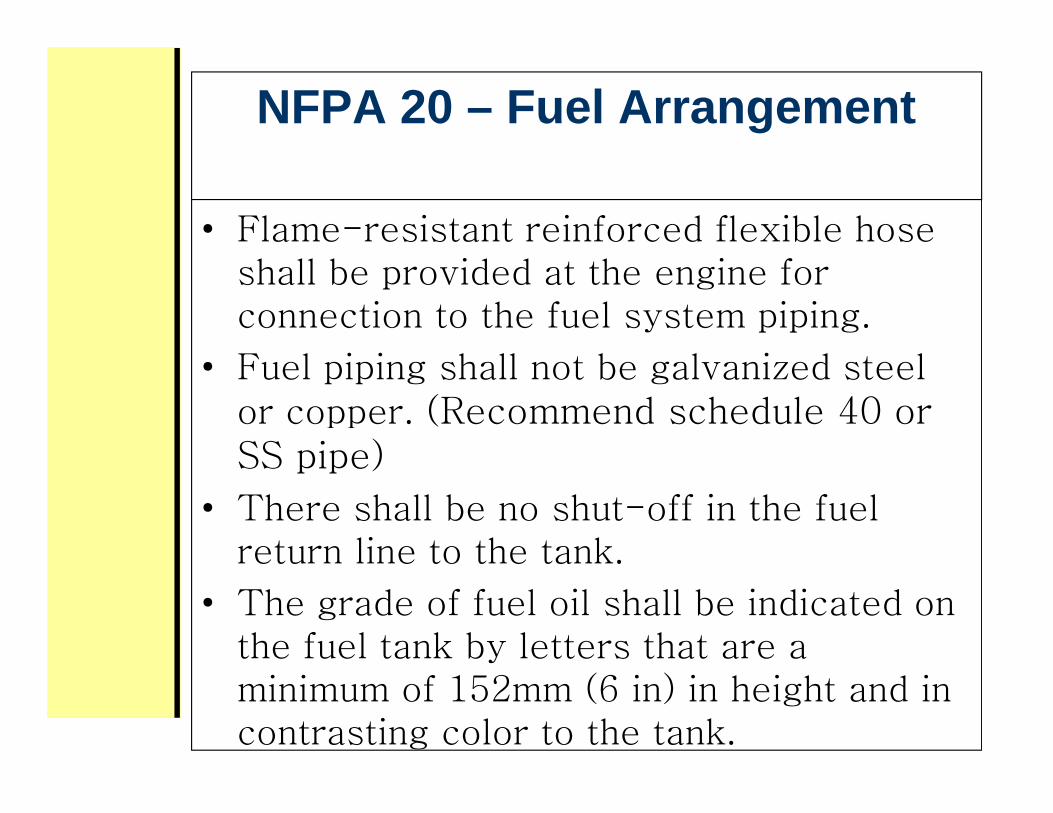
• Flame-resistant reinforced flexible hose shall be provided at the engine for connection to the fuel system piping.
• Fuel piping shall not be galvanized steel or copper (Recommend schedule 40 oror copper. (Recommend schedule 40 or SS pipe)
• There shall be no shut-off in the fuel return line to the tank.
• The grade of fuel oil shall be indicated on the fuel tank by letters that are a minimum of 152mm (6 in) in height and in contrasting color to the tank.

NFPA 20 – Engine Exhaust
• Each engine shall have an independent exhaust system.
• A flex connector shall be used between the engine and the exhaust pipe.
• The flex connector shall not be used for misalignment. (The purpose of the flex is to allow for thermal expansion and for isolating engine vibration from the rest of the exhaust system.)

NFPA 20 – Engine Exhaust
• Back pressure in the exhaust system shall not exceed the engine’s limit.
• The exhaust sizing program on the Clarke website can calculate the back pressure)
• Building supported; not engine supported
I l i h h i• Insulation wrap the exhaust systems in-room components.
• Rain cap on outlet if necessary; tight connections.
• Exhaust system shall terminate outside where hot gases and sparks are discharged to a safe location.

Exhaust Sizing

Exhaust Sizing

Exhaust Sizing

NFPA 20 – System Operation
• Engines shall be started no less than once a week and run for no less than 30 minutes.
• The fire pump shall be started and brought up to rated speed withoutbrought up to rated speed without interruption within 20 seconds.
• In the event of fire pump operation, qualified personnel shall respond to the fire pump location to determine that the fire pump is operating in a satisfactory manner.
NFPA 20 – System Operation
• Batteries shall be kept charged at all times and tested frequently (weekly test) to determine condition.
• Only distilled water shall be used.
B l h ll b k b d• Battery plates shall be kept submerged at all times.

2012 EMISSION SUMMARY
• Beginning Jan 1, 2012
– Diesel Fire Pump drivers with hp’s between 0 bhp and 750 bhp with RPM’s between 0 & 2650 and diesel fire pump drivers with hp’s between 100 and 175 bhp with RPM’s of 2650 and higher, must meet be certified Tier 3 engines.
– NSPS compliant engines manufactured before Jan 1, 2012 in the above horsepower and rpm range can still be sold in 2012.

Clarke Model Nomenclature

UL Coupling for Electric Motors
• Separately coupled-type pumps with electric motor drivers shall be connected by a flexible coupling or flexible connecting shaft.
• All coupling types shall be listed for the service.
• This requirement has actually been around since the 1996 edition of NFPA 20.
• Currently Clarke is the only company that has a UL coupling available for electric motors.

General Requirements
• Fire pumps shall be dedicated to and listed for fire protection service.
• The fire pump shall be properly anchored and grouted and set level on th f d tithe foundation.
• In the event of fire pump operation, qualified personnel shall respond to the fire pump location to determine that the fire pump is operating in a satisfactory manner.

General Requirements
• (Electric Drive) Where the height of a structure is beyond the pumping capacity of the fire department apparatus or where the source of electricity is unreliable, an alternate source of power must be used.
• New 2013 – An alternate source of power for the primary fire pump shall not be required where a backup engine-driven fire pump or a back up electric motor-driven fire pump WITH independent power source is installed.

General Requirements
• Where on-site gen sets are used to supply power to fire pump motors, there shall be of sufficient capacity to allow normal starting & running of the motor while supplying all other simultaneously operated loads.
• New 2013 – The generator shall run & continue to produce rated nameplate power without shutdown or derate for alarms & warnings or failed engine sensors, except for overspeed shutdown.
• New 2013 – The generator fuel tank shall be sized for 8 hours of fire pump operation at 100% in addition to the supply required for other demands.

Clarke Websitewww.clarkefire.com
• Current Models
• Installation & Operation Data
• Emission Data
• Power Curves• Installation Drawings• Contact List• Wiring Diagrams• Technical Manual
• Exhaust Sizing
• Operations Manual
• Spare Parts Illustration
• Installation Checklist
Technical Manual• Service Dealer
Directory• Startup and
Warranty Forms
Related Documents