© 2008 Cummins Inc., Box 3005, Columbus, IN 47202-3005 U.S.A. Printed from QuickServe ® Online. All Rights Reserved. Last Modified: 27-Mar-2014 File: 16-t02-1001a Page 1 of 50 Engine Performance Troubleshooting Tree - ISX CM871 This troubleshooting procedure should be followed for the following symptoms: • Engine Acceleration or Response Poor • Cranking Fuel Pressure is Low • Engine Operating Fuel Pressure is Low • Engine Difficult to Start or Will Not Start (Exhaust Smoke) • Engine Difficult to Start or Will Not Start (No Exhaust Smoke) • Engine Power Output Low • Engine Runs Rough at Idle • Engine Runs Rough or Misfires • Engine Speed Surges at Low or High Idle • Engine Speed Surges Under Load or in Operating Range • Smoke, Black - Excessive • Smoke, White - Excessive • Engine Shuts Off or Dies Unexpectedly or Dies During Deceleration • Engine Starts But Will Not Keep Operating • Engine Will Not Reach Rated Speed (rpm) • Engine Run-on or Will Not Shut Down. How to Use This Troubleshooting Procedure: This symptom tree can be used to troubleshoot all performance-based symptoms listed above. Start by performing Step 1 troubleshooting. Step 2 asks a series of questions and will provide a list of troubleshooting steps to perform, depending on the symptom. Perform the list of troubleshooting in the sequence shown in the Specifications/Repair section of the tree. Shop Talk: Verify the engine control module (ECM) calibration is correct. Check the calibration revision history found on QuickServe™ Online for applicable fixes to the calibration stored in the ECM. If necessary, calibrate the ECM. Use the following procedure in the Troubleshooting and Repair Manual, CM871 and CM876 Electronic Control Systems, ISX and ISM Engines, Bulletin 4021560. Refer to Procedure 019-032 in Section 19.

Welcome message from author
This document is posted to help you gain knowledge. Please leave a comment to let me know what you think about it! Share it to your friends and learn new things together.
Transcript

© 2008 Cummins Inc., Box 3005, Columbus, IN 47202-3005 U.S.A. Printed from QuickServe® Online.All Rights Reserved. Last Modified: 27-Mar-2014
File: 16-t02-1001a Page 1 of 50
Engine Performance Troubleshooting Tree - ISX CM871This troubleshooting procedure should be followed for the following symptoms:• Engine Acceleration or Response Poor• Cranking Fuel Pressure is Low• Engine Operating Fuel Pressure is Low• Engine Difficult to Start or Will Not Start (Exhaust Smoke)• Engine Difficult to Start or Will Not Start (No Exhaust Smoke)• Engine Power Output Low• Engine Runs Rough at Idle• Engine Runs Rough or Misfires• Engine Speed Surges at Low or High Idle• Engine Speed Surges Under Load or in Operating Range• Smoke, Black - Excessive• Smoke, White - Excessive• Engine Shuts Off or Dies Unexpectedly or Dies During Deceleration• Engine Starts But Will Not Keep Operating• Engine Will Not Reach Rated Speed (rpm)• Engine Run-on or Will Not Shut Down.
How to Use This Troubleshooting Procedure:This symptom tree can be used to troubleshoot all performance-based symptoms listed above. Start by performingStep 1 troubleshooting. Step 2 asks a series of questions and will provide a list of troubleshooting steps to perform,depending on the symptom. Perform the list of troubleshooting in the sequence shown in the Specifications/Repairsection of the tree.
Shop Talk:Verify the engine control module (ECM) calibration is correct. Check the calibration revision history found onQuickServe™ Online for applicable fixes to the calibration stored in the ECM. If necessary, calibrate the ECM. Use thefollowing procedure in the Troubleshooting and Repair Manual, CM871 and CM876 Electronic Control Systems, ISXand ISM Engines, Bulletin 4021560. Refer to Procedure 019-032 in Section 19.
© 2008 Cummins Inc., Box 3005, Columbus, IN 47202-3005 U.S.A. Printed from QuickServe® Online.All Rights Reserved. Last Modified: 27-Mar-2014
File: 16-t02-1001a Page 2 of 50
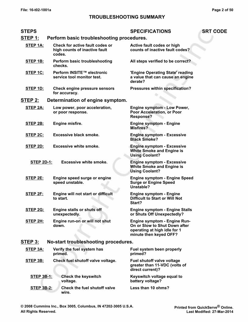
TROUBLESHOOTING SUMMARY
STEPS SPECIFICATIONS SRT CODESTEP 1: Perform basic troubleshooting procedures.
STEP 1A: Check for active fault codes orhigh counts of inactive faultcodes.
Active fault codes or highcounts of inactive fault codes?
STEP 1B: Perform basic troubleshootingchecks.
All steps verified to be correct?
STEP 1C: Perform INSITE™ electronicservice tool monitor test.
'Engine Operating State' readinga value that can cause an enginederate?
STEP 1D: Check engine pressure sensorsfor accuracy.
Pressures within specification?
STEP 2: Determination of engine symptom.STEP 2A: Low power, poor acceleration,
or poor response.Engine symptom - Low Power,Poor Acceleration, or PoorResponse?
STEP 2B: Engine misfire. Engine symptom - EngineMisfires?
STEP 2C: Excessive black smoke. Engine symptom - ExcessiveBlack Smoke?
STEP 2D: Excessive white smoke. Engine symptom - ExcessiveWhite Smoke and Engine isUsing Coolant?
STEP 2D-1: Excessive white smoke. Engine symptom - ExcessiveWhite Smoke and Engine isUsing Coolant?
STEP 2E: Engine speed surge or enginespeed unstable.
Engine symptom - Engine SpeedSurge or Engine SpeedUnstable?
STEP 2F: Engine will not start or difficultto start.
Engine symptom - EngineDifficult to Start or Will NotStart?
STEP 2G: Engine stalls or shuts offunexpectedly.
Engine symptom - Engine Stallsor Shuts Off Unexpectedly?
STEP 2H: Engine run-on or will not shutdown.
Engine symptom - Engine Run-On or Slow to Shut Down afteroperating at high idle for 1minute then keyed OFF?
STEP 3: No-start troubleshooting procedures.STEP 3A: Verify the fuel system has
primed.Fuel system been properlyprimed?
STEP 3B: Check fuel shutoff valve voltage. Fuel shutoff valve voltagegreater than 11-VDC (volts ofdirect current)?
STEP 3B-1: Check the keyswitchvoltage.
Keyswitch voltage equal tobattery voltage?
STEP 3B-2: Check the fuel shutoff valvewire.
Less than 10 ohms?
© 2008 Cummins Inc., Box 3005, Columbus, IN 47202-3005 U.S.A. Printed from QuickServe® Online.All Rights Reserved. Last Modified: 27-Mar-2014
File: 16-t02-1001a Page 3 of 50
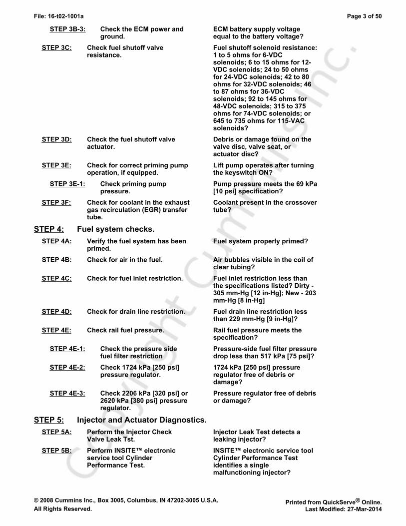
STEP 3B-3: Check the ECM power andground.
ECM battery supply voltageequal to the battery voltage?
STEP 3C: Check fuel shutoff valveresistance.
Fuel shutoff solenoid resistance:1 to 5 ohms for 6-VDCsolenoids; 6 to 15 ohms for 12-VDC solenoids; 24 to 50 ohmsfor 24-VDC solenoids; 42 to 80ohms for 32-VDC solenoids; 46to 87 ohms for 36-VDCsolenoids; 92 to 145 ohms for48-VDC solenoids; 315 to 375ohms for 74-VDC solenoids; or645 to 735 ohms for 115-VACsolenoids?
STEP 3D: Check the fuel shutoff valveactuator.
Debris or damage found on thevalve disc, valve seat, oractuator disc?
STEP 3E: Check for correct priming pumpoperation, if equipped.
Lift pump operates after turningthe keyswitch ON?
STEP 3E-1: Check priming pumppressure.
Pump pressure meets the 69 kPa[10 psi] specification?
STEP 3F: Check for coolant in the exhaustgas recirculation (EGR) transfertube.
Coolant present in the crossovertube?
STEP 4: Fuel system checks.STEP 4A: Verify the fuel system has been
primed.Fuel system properly primed?
STEP 4B: Check for air in the fuel. Air bubbles visible in the coil ofclear tubing?
STEP 4C: Check for fuel inlet restriction. Fuel inlet restriction less thanthe specifications listed? Dirty -305 mm-Hg [12 in-Hg]; New - 203mm-Hg [8 in-Hg]
STEP 4D: Check for drain line restriction. Fuel drain line restriction lessthan 229 mm-Hg [9 in-Hg]?
STEP 4E: Check rail fuel pressure. Rail fuel pressure meets thespecification?
STEP 4E-1: Check the pressure sidefuel filter restriction
Pressure-side fuel filter pressuredrop less than 517 kPa [75 psi]?
STEP 4E-2: Check 1724 kPa [250 psi]pressure regulator.
1724 kPa [250 psi] pressureregulator free of debris ordamage?
STEP 4E-3: Check 2206 kPa [320 psi] or2620 kPa [380 psi] pressureregulator.
Pressure regulator free of debrisor damage?
STEP 5: Injector and Actuator Diagnostics.STEP 5A: Perform the Injector Check
Valve Leak Tst.Injector Leak Test detects aleaking injector?
STEP 5B: Perform INSITE™ electronicservice tool CylinderPerformance Test.
INSITE™ electronic service toolCylinder Performance Testidentifies a singlemalfunctioning injector?

© 2008 Cummins Inc., Box 3005, Columbus, IN 47202-3005 U.S.A. Printed from QuickServe® Online.All Rights Reserved. Last Modified: 27-Mar-2014
File: 16-t02-1001a Page 4 of 50
STEP 5B-1: Perform INSITE™ electronicservice tool CylinderPerformance Test at 600rpm.
INSITE™ electronic service toolCylinder Performance Testidentifies a singlemalfunctioning injector?
STEP 5B-2: Perform INSITE™ electronicservice tool CylinderPerformance Test at 700rpm.
INSITE™ electronic service toolCylinder Performance Testidentifies a singlemalfunctioning injector?
STEP 5B-3: Perform INSITE™ electronicservice tool CylinderPerformance Test at 800rpm.
INSITE™ electronic service toolCylinder Performance Testidentifies a singlemalfunctioning injector?
STEP 5C: Perform INSITE™ electronicservice tool Cylinder CutoutTest.
Cylinders pass the CylinderCutout Test?
STEP 5C-1: Perform INSITE™ electronicservice tool Cylinder CutoutTest on both injector banks.
Malfunctioning bank of injectorsisolated by operating the engineon either bank of injectors?
STEP 5C-2: Perform INSITE™ electronicservice tool Cylinder CutoutTest.
Malfunctioning injector isolatedby operating the engine on asingle injector?
STEP 5C-3: Verify overheadadjustments are correct forthe suspectedmalfunctioning injector.
Overhead settings within thereset limits outlines inProcedure 003-004 in Section 3?
STEP 5D: Swap the front and rearmetering actuators.
Cylinder Performance Test findsa malfunctioning bank?
STEP 5E: Swap the front and rear timingactuators.
Malfunctioning bank follows thetiming actuator?
STEP 5F: Perform the Timing ActuatorFlow Test.
Timing Actuator Flow Test findsa malfunctioning actuator?
STEP 5G: Monitor the engine percent loadvalue with INSITE™ electronicservice tool. (Perform this stepfor troubleshooting low poweronly.)
Engine percent load valueconsistently above 8 percent?
STEP 6: Air handling diagnostic checks.STEP 6A: Start the engine and read the
fault codes.Active fault codes?
STEP 6B: Check air intake restriction. Air intake restriction greaterthan 635 mm-H2O [25 in-H2O] fora used air filter or 254 mm-H2O[10 in-H2O] for a new filter?
STEP 6C: Inspect the charge-air cooler. Pressure drop 34 kPa [5 psi] orless in 15 seconds?
STEP 6D: Inspect the turbocharger bladesfor damage.
Damage found on turbochargerblades?
STEP 6E: Inspect the turbocharger shaftmovement.
Nozzle slides evenly from stopto stop and gear teethundamaged?
STEP 7: Check exhaust gas recirculation (EGR) valve for proper operation.
© 2008 Cummins Inc., Box 3005, Columbus, IN 47202-3005 U.S.A. Printed from QuickServe® Online.All Rights Reserved. Last Modified: 27-Mar-2014
File: 16-t02-1001a Page 5 of 50
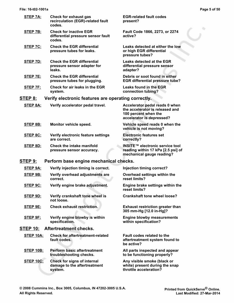
STEP 7A: Check for exhaust gasrecirculation (EGR)-related faultcodes.
EGR-related fault codespresent?
STEP 7B: Check for inactive EGRdifferential pressure sensor faultcodes.
Fault Code 1866, 2273, or 2274active?
STEP 7C: Check the EGR differentialpressure tubes for leaks.
Leaks detected at either the lowor high EGR differentialpressure tubes?
STEP 7D: Check the EGR differentialpressure sensor adapter forleaks.
Leaks detected at the EGRdifferential pressure sensoradapter?
STEP 7E: Check the EGR differentialpressure tubes for plugging.
Debris or soot found in eitherEGR differential pressure tube?
STEP 7F: Check for air leaks in the EGRsystem.
Leaks found in the EGRconnection tubing?
STEP 8: Verify electronic features are operating correctly.STEP 8A: Verify accelerator pedal travel. Accelerator pedal reads 0 when
the accelerator is released and100 percent when theaccelerator is depressed?
STEP 8B: Monitor vehicle speed. Vehicle speed reads 0 when thevehicle is not moving?
STEP 8C: Verify electronic feature settingsare correct.
Electronic features setcorrectly?
STEP 8D: Check the intake manifoldpressure sensor accuracy.
INSITE™ electronic service toolreading within 17 kPa [2.5 psi] ofmechanical gauge reading?
STEP 9: Perform base engine mechanical checks.STEP 9A: Verify injection timing is correct. Injection timing correct?STEP 9B: Verify overhead adjustments are
correct.Overhead settings within thereset limits?
STEP 9C: Verify engine brake adjustment. Engine brake settings within thereset limits?
STEP 9D: Verify crankshaft tone wheel isnot loose.
Crankshaft tone wheel loose?
STEP 9E: Check exhaust restriction. Exhaust restriction greater than305 mm-Hg [12.0 in-Hg]?
STEP 9F: Verify engine blowby is withinspecification.
Engine blowby measurementswithin specification?
STEP 10: Aftertreatment checks.STEP 10A: Check for aftertreatment-related
fault codes.Fault codes related to theaftertreatment system found tobe active?
STEP 10B: Perform basic aftertreatmenttroubleshooting checks.
All parts inspected and appearto be functioning properly?
STEP 10C: Check for signs of internaldamage to the aftertreatmentsystem.
Any visible smoke (black orwhite) present during the snapthrottle acceleration?

© 2008 Cummins Inc., Box 3005, Columbus, IN 47202-3005 U.S.A. Printed from QuickServe® Online.All Rights Reserved. Last Modified: 27-Mar-2014
File: 16-t02-1001a Page 6 of 50
STEP 10D: Check exhaust restriction. Exhaust restriction greater than305 mm-Hg [12.0 in-Hg]?
TROUBLESHOOTING STEP
STEP 1: Perform basic troubleshooting procedures.STEP 1A: Check for active fault codes or high counts of inactive fault codes.
Condition:• Connect INSITE™ electronic service tool.• Turn keyswitch ON.
Action Specification/Repair Next Step
Check for active fault codes or high counts ofinactive fault codes.• Use INSITE™ electronic service tool to read
the fault codes.
Active fault codes or high counts of inactivefault codes?YES
Go toappropriatefault codetroubleshooting tree
Active fault codes or high counts of inactivefault codes?NO
1B
STEP 1B: Perform basic troubleshooting checks.
Condition:N/A
Action Specification/Repair Next Step
The following items must be checked or verifiedbefore continuing:• Verify the fuel level in the tanks.• Verify there have not been any changes to
CPL components on the engine.• Verify fuel grade is correct for the application.• Verify the engine is operating within the
recommended altitude.• Verify engine oil is at the correct level.• Verify engine parasitics have not changed.• Verify engine duty cycle has not changed.• Verify engine cranking speed is greater than
150 rpm.• Verify battery voltage is within specification.
All steps verified to be correct?YES
1C
All steps verified to be correct?NORepair:Correct the out-of-specification item andverify complaint is no longer present afterrepair.
Repaircomplete
© 2008 Cummins Inc., Box 3005, Columbus, IN 47202-3005 U.S.A. Printed from QuickServe® Online.All Rights Reserved. Last Modified: 27-Mar-2014
File: 16-t02-1001a Page 7 of 50
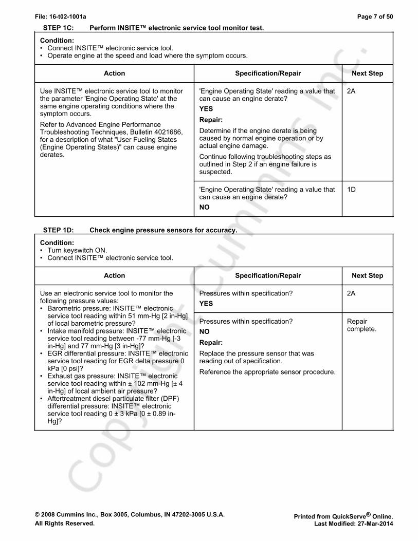
STEP 1C: Perform INSITE™ electronic service tool monitor test.
Condition:• Connect INSITE™ electronic service tool.• Operate engine at the speed and load where the symptom occurs.
Action Specification/Repair Next Step
Use INSITE™ electronic service tool to monitorthe parameter 'Engine Operating State' at thesame engine operating conditions where thesymptom occurs.Refer to Advanced Engine PerformanceTroubleshooting Techniques, Bulletin 4021686,for a description of what "User Fueling States(Engine Operating States)" can cause enginederates.
'Engine Operating State' reading a value thatcan cause an engine derate?YESRepair:Determine if the engine derate is beingcaused by normal engine operation or byactual engine damage.Continue following troubleshooting steps asoutlined in Step 2 if an engine failure issuspected.
2A
'Engine Operating State' reading a value thatcan cause an engine derate?NO
1D
STEP 1D: Check engine pressure sensors for accuracy.
Condition:• Turn keyswitch ON.• Connect INSITE™ electronic service tool.
Action Specification/Repair Next Step
Use an electronic service tool to monitor thefollowing pressure values:• Barometric pressure: INSITE™ electronic
service tool reading within 51 mm-Hg [2 in-Hg]of local barometric pressure?
• Intake manifold pressure: INSITE™ electronicservice tool reading between -77 mm-Hg [-3in-Hg] and 77 mm-Hg [3 in-Hg]?
• EGR differential pressure: INSITE™ electronicservice tool reading for EGR delta pressure 0kPa [0 psi]?
• Exhaust gas pressure: INSITE™ electronicservice tool reading within ± 102 mm-Hg [± 4in-Hg] of local ambient air pressure?
• Aftertreatment diesel particulate filter (DPF)differential pressure: INSITE™ electronicservice tool reading 0 ± 3 kPa [0 ± 0.89 in-Hg]?
Pressures within specification?YES
2A
Pressures within specification?NORepair:Replace the pressure sensor that wasreading out of specification.Reference the appropriate sensor procedure.
Repaircomplete.
© 2008 Cummins Inc., Box 3005, Columbus, IN 47202-3005 U.S.A. Printed from QuickServe® Online.All Rights Reserved. Last Modified: 27-Mar-2014
File: 16-t02-1001a Page 8 of 50
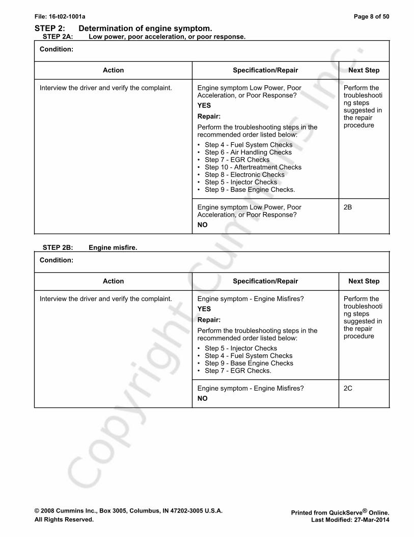
STEP 2: Determination of engine symptom.STEP 2A: Low power, poor acceleration, or poor response.
Condition:
Action Specification/Repair Next Step
Interview the driver and verify the complaint. Engine symptom Low Power, PoorAcceleration, or Poor Response?YESRepair:Perform the troubleshooting steps in therecommended order listed below:• Step 4 - Fuel System Checks• Step 6 - Air Handling Checks• Step 7 - EGR Checks• Step 10 - Aftertreatment Checks• Step 8 - Electronic Checks• Step 5 - Injector Checks• Step 9 - Base Engine Checks.
Perform thetroubleshooting stepssuggested inthe repairprocedure
Engine symptom Low Power, PoorAcceleration, or Poor Response?NO
2B
STEP 2B: Engine misfire.
Condition:
Action Specification/Repair Next Step
Interview the driver and verify the complaint. Engine symptom - Engine Misfires?YESRepair:Perform the troubleshooting steps in therecommended order listed below:• Step 5 - Injector Checks• Step 4 - Fuel System Checks• Step 9 - Base Engine Checks• Step 7 - EGR Checks.
Perform thetroubleshooting stepssuggested inthe repairprocedure
Engine symptom - Engine Misfires?NO
2C
© 2008 Cummins Inc., Box 3005, Columbus, IN 47202-3005 U.S.A. Printed from QuickServe® Online.All Rights Reserved. Last Modified: 27-Mar-2014
File: 16-t02-1001a Page 9 of 50
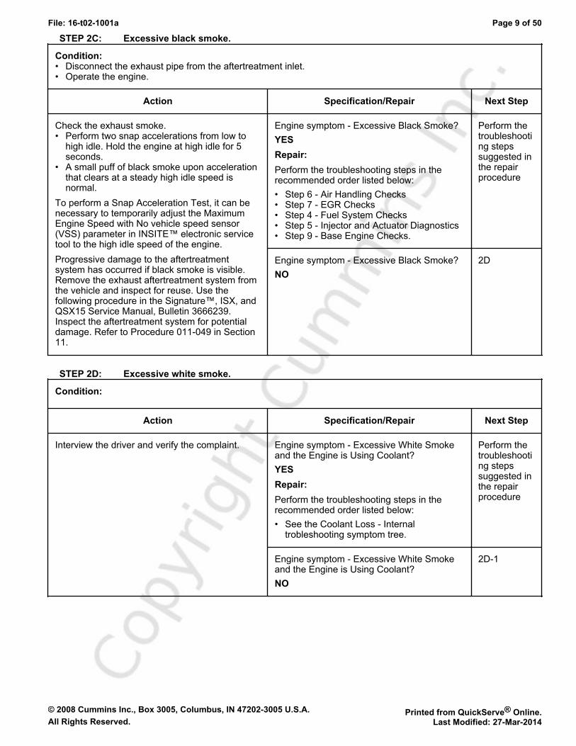
STEP 2C: Excessive black smoke.
Condition:• Disconnect the exhaust pipe from the aftertreatment inlet.• Operate the engine.
Action Specification/Repair Next Step
Check the exhaust smoke.• Perform two snap accelerations from low to
high idle. Hold the engine at high idle for 5seconds.
• A small puff of black smoke upon accelerationthat clears at a steady high idle speed isnormal.
To perform a Snap Acceleration Test, it can benecessary to temporarily adjust the MaximumEngine Speed with No vehicle speed sensor(VSS) parameter in INSITE™ electronic servicetool to the high idle speed of the engine.Progressive damage to the aftertreatmentsystem has occurred if black smoke is visible.Remove the exhaust aftertreatment system fromthe vehicle and inspect for reuse. Use thefollowing procedure in the Signature™, ISX, andQSX15 Service Manual, Bulletin 3666239.Inspect the aftertreatment system for potentialdamage. Refer to Procedure 011-049 in Section11.
Engine symptom - Excessive Black Smoke?YESRepair:Perform the troubleshooting steps in therecommended order listed below:• Step 6 - Air Handling Checks• Step 7 - EGR Checks• Step 4 - Fuel System Checks• Step 5 - Injector and Actuator Diagnostics• Step 9 - Base Engine Checks.
Perform thetroubleshooting stepssuggested inthe repairprocedure
Engine symptom - Excessive Black Smoke?NO
2D
STEP 2D: Excessive white smoke.
Condition:
Action Specification/Repair Next Step
Interview the driver and verify the complaint. Engine symptom - Excessive White Smokeand the Engine is Using Coolant?YESRepair:Perform the troubleshooting steps in therecommended order listed below:• See the Coolant Loss - Internal
trobleshooting symptom tree.
Perform thetroubleshooting stepssuggested inthe repairprocedure
Engine symptom - Excessive White Smokeand the Engine is Using Coolant?NO
2D-1

© 2008 Cummins Inc., Box 3005, Columbus, IN 47202-3005 U.S.A. Printed from QuickServe® Online.All Rights Reserved. Last Modified: 27-Mar-2014
File: 16-t02-1001a Page 10 of 50
STEP 2D-1: Excessive white smoke.
Condition:
Action Specification/Repair Next Step
Interview the driver and verify the complaint. Engine symptom - Excessive White Smokeand the Engine is not Using Coolant?YESRepair:Perform the troubleshooting steps in therecommended order listed below:• Step 4 - Fuel System Checks• Step 5 - Injector Checks• Step 10 - Aftertreatment Checks• Step 6 - Air Handling Checks• Step 9 - Base Engine Checks.
Perform thetroubleshooting stepssuggested inthe repairprocedure
Engine symptom - Excessive White Smokeand the Engine is not Using Coolant?NO
2E
STEP 2E: Engine speed surge or engine speed unstable.
Condition:
Action Specification/Repair Next Step
Interview the driver and verify the complaint. Engine symptom - Engine Speed Surge orEngine Speed Unstable?YESRepair:Perform the troubleshooting steps in therecommended order listed below:• Step 4 - Fuel System Checks• Step 5 - Injector Checks• Step 7 - EGR Checks• Step 6 - Air Handling Checks• Step 8 - Electronics Checks• Step 9 - Base Engine Checks.
Perform thetroubleshooting stepssuggested inthe repairprocedure
Engine symptom - Engine Speed Surge orEngine Speed Unstable?NO
2F
© 2008 Cummins Inc., Box 3005, Columbus, IN 47202-3005 U.S.A. Printed from QuickServe® Online.All Rights Reserved. Last Modified: 27-Mar-2014
File: 16-t02-1001a Page 11 of 50
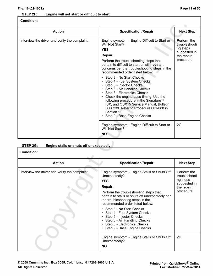
STEP 2F: Engine will not start or difficult to start.
Condition:
Action Specification/Repair Next Step
Interview the driver and verify the complaint. Engine symptom - Engine Difficult to Start orWill Not Start?YESRepair:Perform the troubleshooting steps thatpertain to difficult to start or will not startconcerns per the troubleshooting steps in therecommended order listed below:• Step 3 - No Start Checks• Step 4 - Fuel System Checks• Step 5 - Injector Checks• Step 6 - Air Handling Checks• Step 8 - Electronics Checks• Check the engine base timing. Use the
following procedure in the Signature™,ISX, and QSX15 Service Manual, Bulletin3666239. Refer to Procedure 001-088 inSection 1.
• Step 9 - Base Engine Checks.
Perform thetroubleshooting stepssuggested inthe repairprocedure
Engine symptom - Engine Difficult to Start orWill Not Start?NO
2G
STEP 2G: Engine stalls or shuts off unexpectedly.
Condition:
Action Specification/Repair Next Step
Interview the driver and verify the complaint. Engine symptom - Engine Stalls or Shuts OffUnexpectedly?YESRepair:Perform the troubleshooting steps thatpertain to stalls or shuts off unexpectedly perthe troubleshooting steps in therecommended order listed below:• Step 3 - No Start Checks• Step 4 - Fuel System Checks• Step 5 - Injector Checks• Step 6 - Air Handling Checks• Step 8 - Electronics Checks• Step 9 - Base Engine Checks.
Perform thetroubleshooting stepssuggested inthe repairprocedure
Engine symptom - Engine Stalls or Shuts OffUnexpectedly?NO
2H
© 2008 Cummins Inc., Box 3005, Columbus, IN 47202-3005 U.S.A. Printed from QuickServe® Online.All Rights Reserved. Last Modified: 27-Mar-2014
File: 16-t02-1001a Page 12 of 50
STEP 2H: Engine run-on or will not shut down.
Condition:
Action Specification/Repair Next Step
Interview the driver and verify the complaint. Engine symptom - Engine Run-On or Slow toShut Down after operating at high idle for 1minute then keyed OFF?YESRepair:Perform the troubleshooting steps in therecommended order listed below:• Step 5 - Injector Checks• Step 4 - Fuel System Checks• Step 9 - Base Engine Checks.
Perform thetroubleshooting stepssuggested inthe repairprocedure
Engine symptom - Engine Run-On or Slow toShut Down after operating at high idle for 1minute then keyed OFF?NO
Return toappropriatesymptomtree
STEP 3: No-start troubleshooting procedures.STEP 3A: Verify the fuel system has been primed.
Condition:• Turn keyswitch OFF.
Action Specification/Repair Next Step
Verify the fuel system has been primed.If entering this tree after a component has beenreplaced in the fuel system, or after the enginehas been run out of fuel, verify the fuel systemhas been properly primed before proceeding.• Use the following procedure for fuel system
priming found in the Signature™, ISX, andQSX Service Manual, Bulletin 3666239. Referto Procedure 006-015 in Section 6.
Fuel system properly primed?YES
3B
Fuel system properly primed?NORepair:Prime the fuel system.• Use the following procedure for fuel
system priming found in the Signature™,ISX, and QSX Service Manual, Bulletin3666239. Refer to Procedure 006-015 inSection 6.
Repaircomplete
© 2008 Cummins Inc., Box 3005, Columbus, IN 47202-3005 U.S.A. Printed from QuickServe® Online.All Rights Reserved. Last Modified: 27-Mar-2014
File: 16-t02-1001a Page 13 of 50
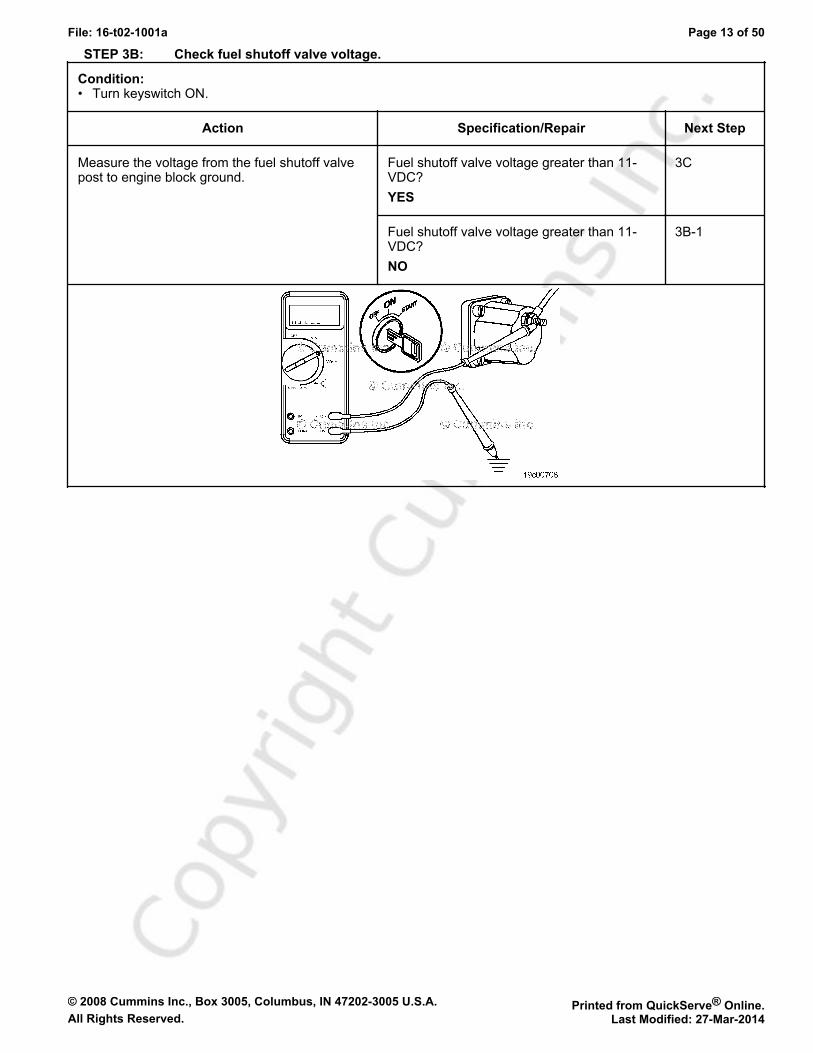
STEP 3B: Check fuel shutoff valve voltage.
Condition:• Turn keyswitch ON.
Action Specification/Repair Next Step
Measure the voltage from the fuel shutoff valvepost to engine block ground.
Fuel shutoff valve voltage greater than 11-VDC?YES
3C
Fuel shutoff valve voltage greater than 11-VDC?NO
3B-1

© 2008 Cummins Inc., Box 3005, Columbus, IN 47202-3005 U.S.A. Printed from QuickServe® Online.All Rights Reserved. Last Modified: 27-Mar-2014
File: 16-t02-1001a Page 14 of 50
STEP 3B-1: Check ECM keyswitch voltage.
Condition:• Turn keyswitch OFF.• Disconnect the original equipment manufacturer (OEM) harness from the ECM.• Turn keyswitch ON.
Action Specification/Repair Next Step
Measure the voltage from the keyswitch inputSIGNAL wire of the OEM harness to engineblock ground.
Keyswitch voltage equal to battery voltage?YES
3B-2
Keyswitch voltage equal to battery voltage?NORepair:Repair or replace the OEM power harness,or keyswitch, or check the batteryconnections.Use the following procedure found in the ISXCM871 and ISM CM876 Electronic ControlSystem, Bulletin 4021560. Refer toProcedure 019-064 in Section 19.
Repaircomplete
© 2008 Cummins Inc., Box 3005, Columbus, IN 47202-3005 U.S.A. Printed from QuickServe® Online.All Rights Reserved. Last Modified: 27-Mar-2014
File: 16-t02-1001a Page 15 of 50
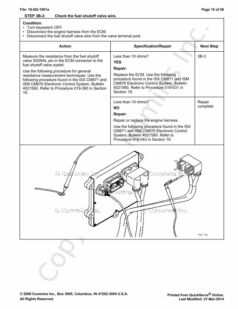
STEP 3B-2: Check the fuel shutoff valve wire.
Condition:• Turn keyswitch OFF.• Disconnect the engine harness from the ECM.• Disconnect the fuel shutoff valve wire from the valve terminal post.
Action Specification/Repair Next Step
Measure the resistance from the fuel shutoffvalve SIGNAL pin in the ECM connector to thefuel shutoff valve eyelet.Use the following procedure for generalresistance measurement techniques. Use thefollowing procedure found in the ISX CM871 andISM CM876 Electronic Control System, Bulletin4021560. Refer to Procedure 019-360 in Section19.
Less than 10 ohms?YESRepair:Replace the ECM. Use the followingprocedure found in the ISX CM871 and ISMCM876 Electronic Control System, Bulletin4021560. Refer to Procedure 019-031 inSection 19.
3B-3
Less than 10 ohms?NORepair:Repair or replace the engine harness.Use the following procedure found in the ISXCM871 and ISM CM876 Electronic ControlSystem, Bulletin 4021560. Refer toProcedure 019-043 in Section 19.
Repaircomplete
© 2008 Cummins Inc., Box 3005, Columbus, IN 47202-3005 U.S.A. Printed from QuickServe® Online.All Rights Reserved. Last Modified: 27-Mar-2014
File: 16-t02-1001a Page 16 of 50
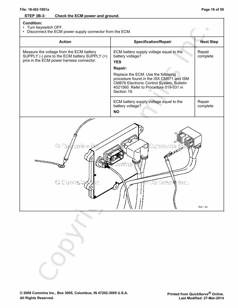
STEP 3B-3: Check the ECM power and ground.
Condition:• Turn keyswitch OFF.• Disconnect the ECM power supply connector from the ECM.
Action Specification/Repair Next Step
Measure the voltage from the ECM batterySUPPLY (-) pins to the ECM battery SUPPLY (+)pins in the ECM power harness connector.
ECM battery supply voltage equal to thebattery voltage?YESRepair:Replace the ECM. Use the followingprocedure found in the ISX CM871 and ISMCM876 Electronic Control System, Bulletin4021560. Refer to Procedure 019-031 inSection 19.
Repaircomplete
ECM battery supply voltage equal to thebattery voltage?NO
Repaircomplete

© 2008 Cummins Inc., Box 3005, Columbus, IN 47202-3005 U.S.A. Printed from QuickServe® Online.All Rights Reserved. Last Modified: 27-Mar-2014
File: 16-t02-1001a Page 17 of 50
STEP 3C: Check fuel shutoff valve resistance.
Condition:• Turn keyswitch OFF.• Disconnect fuel shutoff valve SIGNAL wire from the fuel shutoff solenoid.• Be sure fuel shutoff valve temperature is between 20°C [68°F] and 25°C [78°F].
Action Specification/Repair Next Step
Measure the resistance from the fuel shutoffsolenoid post to engine block ground.The fuel shutoff solenoid must be between 20°C[68°F] and 25°C [78°F] before using theresistance specifications listed.Use the following procedure for generalresistance measurement techniques. Use thefollowing procedure found in the ISX CM871 andISM CM876 Electronic Control System, Bulletin4021560. Refer to Procedure 019-360 in Section19.
Fuel shutoff solenoid resistance:• 1 to 5 ohms for 6-VDC solenoids• 6 to 15 ohms for 12-VDC solenoids• 24 to 50 ohms for 24-VDC solenoids• 42 to 80 ohms for 32-VDC solenoids• 46 to 87 ohms for 36-VDC solenoids• 92 to 145 ohms for 48-VDC solenoids• 315 to 375 ohms for 74-VDC solenoids• 645 to 735 ohms for 115-VAC solenoids?YES
3D
Fuel shutoff solenoid resistance:• 1 to 5 ohms for 6-VDC solenoids• 6 to 15 ohms for 12-VDC solenoids• 24 to 50 ohms for 24-VDC solenoids• 42 to 80 ohms for 32-VDC solenoids• 46 to 87 ohms for 36-VDC solenoids• 92 to 145 ohms for 48-VDC solenoids• 315 to 375 ohms for 74-VDC solenoids• 645 to 735 ohms for 115-VAC solenoids?NORepair:Replace the fuel shutoff solenoid. Use thefollowing procedure found in the ISX CM871and ISM CM876 Electronic Control System,Bulletin 4021560. Refer to Procedure019-050 in Section 19.
Repaircomplete
© 2008 Cummins Inc., Box 3005, Columbus, IN 47202-3005 U.S.A. Printed from QuickServe® Online.All Rights Reserved. Last Modified: 27-Mar-2014
File: 16-t02-1001a Page 18 of 50
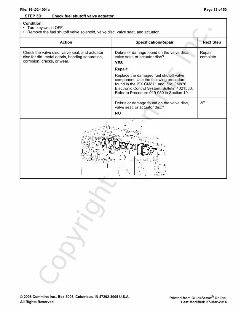
STEP 3D: Check fuel shutoff valve actuator.
Condition:• Turn keyswitch OFF.• Remove the fuel shutoff valve solenoid, valve disc, valve seat, and actuator.
Action Specification/Repair Next Step
Check the valve disc, valve seat, and actuatordisc for dirt, metal debris, bonding separation,corrosion, cracks, or wear.
Debris or damage found on the valve disc,valve seat, or actuator disc?YESRepair:Replace the damaged fuel shutoff valvecomponent. Use the following procedurefound in the ISX CM871 and ISM CM876Electronic Control System, Bulletin 4021560.Refer to Procedure 019-050 in Section 19.
Repaircomplete
Debris or damage found on the valve disc,valve seat, or actuator disc?NO
3E
© 2008 Cummins Inc., Box 3005, Columbus, IN 47202-3005 U.S.A. Printed from QuickServe® Online.All Rights Reserved. Last Modified: 27-Mar-2014
File: 16-t02-1001a Page 19 of 50
STEP 3E: Check for correct priming pump operation, if equipped.
Condition:• Turn keyswitch OFF.• Assemble fuel shutoff valve components.• Turn keyswitch ON.
Action Specification/Repair Next Step
Listen for lift pump operation after the keyswitchis turned to the ON position.Not all ISX engines use a priming pump and notall priming pumps actuate at keyswitch ON.Verify the type of pump system on the enginebefore beginning this step.
Lift pump operates after turning thekeyswitch ON or does the engine not use apriming pump?YES
3E-1
Lift pump operates after turning thekeyswitch ON or does the engine not use apriming pump?NORepair:Check or replace lift pump. Use the followingprocedure in the Signature™, ISX, andQSX15 Service Manual, Bulletin 3666239.Refer to Procedure 005-045 in Section 5.
Repaircomplete
STEP 3E-1: Check priming pump pressure.
Condition:• Turn keyswitch OFF.• Turn keyswitch ON.
Action Specification/Repair Next Step
Measure the priming pressure at the quickconnect fitting located on the top of theintegrated fuel system module (IFSM).Use the following procedure in the Signature™,ISX, and QSX15 Service Manual, Bulletin3666239. Refer to Procedure 005-045 in Section5.
Pump pressure meets the 69 kPa [10 psi]specification?YES
3F
Pump pressure meets the 69 kPa [10 psi]specification?NO
Replace thelift pump.Use thefollowingprocedure intheSignature™,ISX, andQSX15ServiceManual,Bulletin3666239.Refer toProcedure005-045 inSection 5.
© 2008 Cummins Inc., Box 3005, Columbus, IN 47202-3005 U.S.A. Printed from QuickServe® Online.All Rights Reserved. Last Modified: 27-Mar-2014
File: 16-t02-1001a Page 20 of 50
STEP 3F: Check for coolant in the EGR transfer tube.
Condition:• Turn keyswitch OFF.
Action Specification/Repair Next Step
Remove the EGR transfer hose from the EGRcooler outlet.
Coolant present in the crossover tube?YESRepair:See the Coolant Loss - Internal symptomtree.
Repaircomplete
Coolant present in the crossover tube?NORepair:Perform the next troubleshooting procedureas outlined in Step 2
2A
STEP 4: Fuel system checks.STEP 4A: Verify the fuel system has been primed.
Condition:• Turn keyswitch OFF.
Action Specification/Repair Next Step
Verify the fuel system has been primed.If entering this tree after a component has beenreplaced in the fuel system, or after the enginehas been emptied of fuel, verify the fuel systemhas been properly primed before proceeding.• Use the following procedure for fuel system
priming found in the Signature™, ISX, andQSX Service Manual, Bulletin 3666239. Referto Procedure 006-015 in Section 6.
Fuel system been properly primed?YES
4B
Fuel system been properly primed?NORepair:Prime the fuel system.• Use the following procedure for fuel
system priming found in the Signature™,ISX, and QSX Service Manual, Bulletin3666239. Refer to Procedure 006-015 inSection 6.
Repaircomplete
© 2008 Cummins Inc., Box 3005, Columbus, IN 47202-3005 U.S.A. Printed from QuickServe® Online.All Rights Reserved. Last Modified: 27-Mar-2014
File: 16-t02-1001a Page 21 of 50
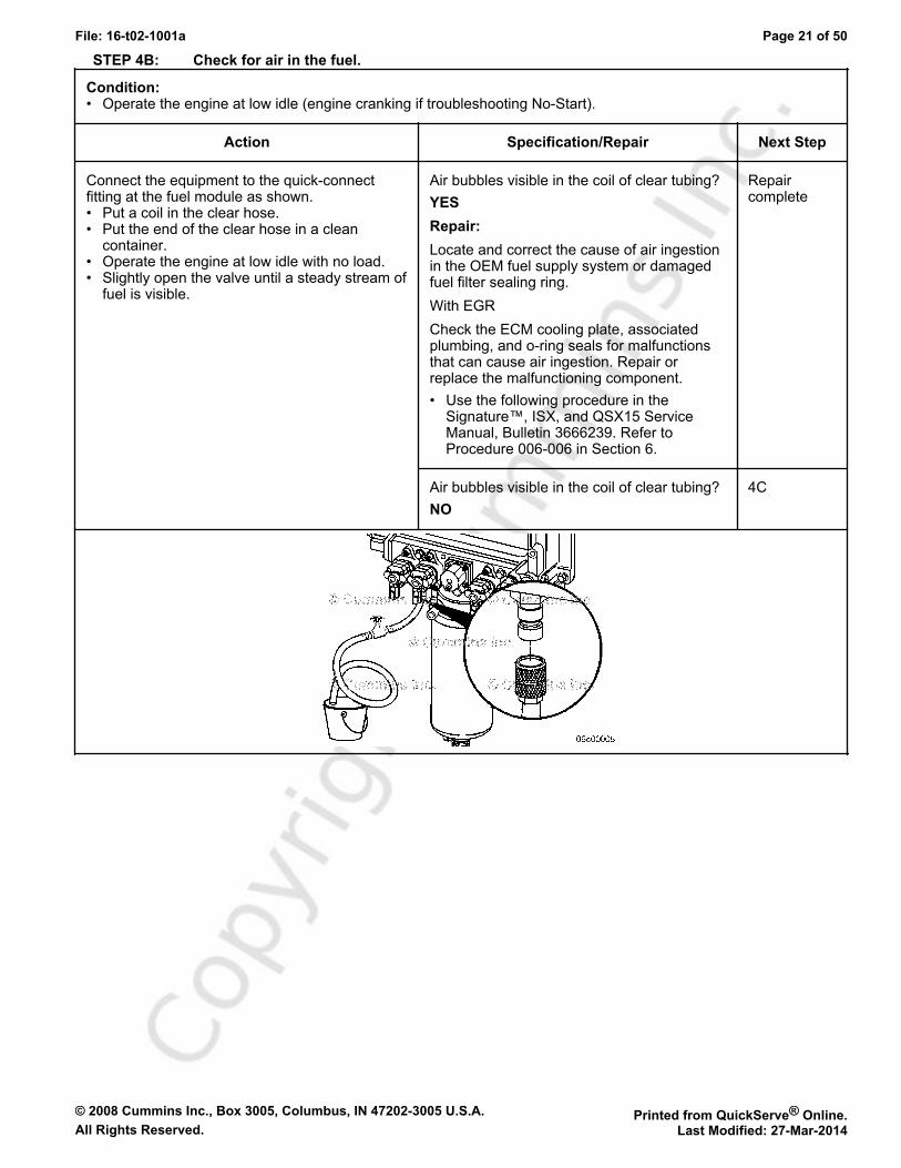
STEP 4B: Check for air in the fuel.
Condition:• Operate the engine at low idle (engine cranking if troubleshooting No-Start).
Action Specification/Repair Next Step
Connect the equipment to the quick-connectfitting at the fuel module as shown.• Put a coil in the clear hose.• Put the end of the clear hose in a clean
container.• Operate the engine at low idle with no load.• Slightly open the valve until a steady stream of
fuel is visible.
Air bubbles visible in the coil of clear tubing?YESRepair:Locate and correct the cause of air ingestionin the OEM fuel supply system or damagedfuel filter sealing ring.With EGRCheck the ECM cooling plate, associatedplumbing, and o-ring seals for malfunctionsthat can cause air ingestion. Repair orreplace the malfunctioning component.• Use the following procedure in the
Signature™, ISX, and QSX15 ServiceManual, Bulletin 3666239. Refer toProcedure 006-006 in Section 6.
Repaircomplete
Air bubbles visible in the coil of clear tubing?NO
4C
© 2008 Cummins Inc., Box 3005, Columbus, IN 47202-3005 U.S.A. Printed from QuickServe® Online.All Rights Reserved. Last Modified: 27-Mar-2014
File: 16-t02-1001a Page 22 of 50
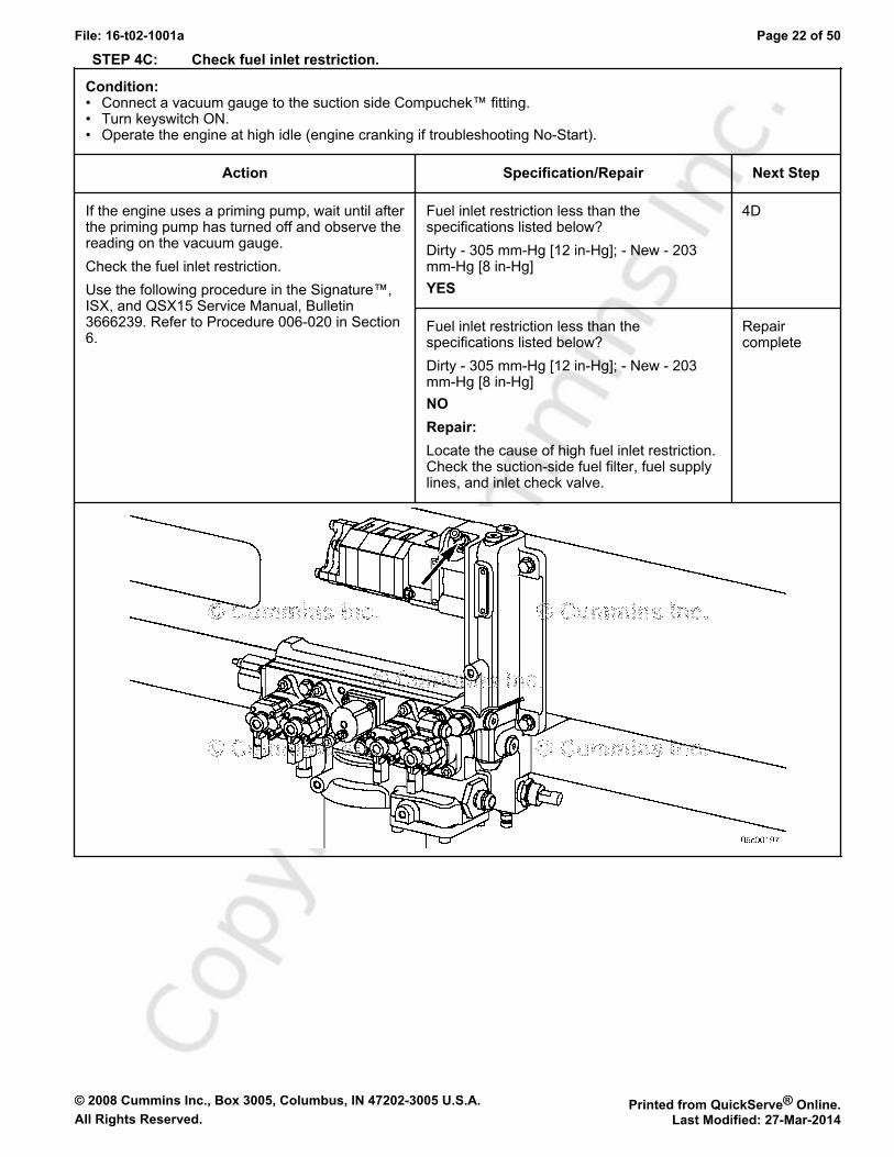
STEP 4C: Check fuel inlet restriction.
Condition:• Connect a vacuum gauge to the suction side Compuchek™ fitting.• Turn keyswitch ON.• Operate the engine at high idle (engine cranking if troubleshooting No-Start).
Action Specification/Repair Next Step
If the engine uses a priming pump, wait until afterthe priming pump has turned off and observe thereading on the vacuum gauge.Check the fuel inlet restriction.Use the following procedure in the Signature™,ISX, and QSX15 Service Manual, Bulletin3666239. Refer to Procedure 006-020 in Section6.
Fuel inlet restriction less than thespecifications listed below?Dirty - 305 mm-Hg [12 in-Hg]; - New - 203mm-Hg [8 in-Hg]YES
4D
Fuel inlet restriction less than thespecifications listed below?Dirty - 305 mm-Hg [12 in-Hg]; - New - 203mm-Hg [8 in-Hg]NORepair:Locate the cause of high fuel inlet restriction.Check the suction-side fuel filter, fuel supplylines, and inlet check valve.
Repaircomplete

© 2008 Cummins Inc., Box 3005, Columbus, IN 47202-3005 U.S.A. Printed from QuickServe® Online.All Rights Reserved. Last Modified: 27-Mar-2014
File: 16-t02-1001a Page 23 of 50
STEP 4D: Check drain line restriction.
Condition:• Connect pressure gauge, Part Number 3375278.• Turn keyswitch ON.• Operate the engine at high idle (engine cranking if troubleshooting No-Start).
Action Specification/Repair Next Step
Observe reading on the pressure gauge. Fuel drain line restriction less than 229 mm-Hg [9 in-Hg]?YES
4E
Fuel drain line restriction less than 229 mm-Hg [9 in-Hg]?NORepair:Locate the cause of high fuel drain linerestriction in the OEM fuel return line.
Repaircomplete
© 2008 Cummins Inc., Box 3005, Columbus, IN 47202-3005 U.S.A. Printed from QuickServe® Online.All Rights Reserved. Last Modified: 27-Mar-2014
File: 16-t02-1001a Page 24 of 50
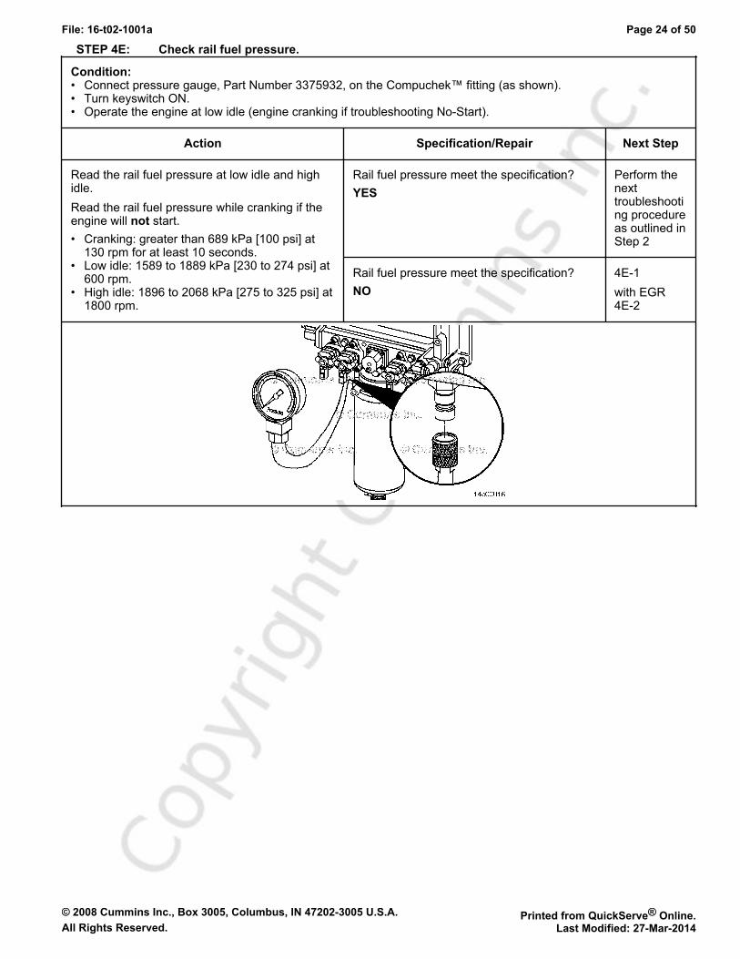
STEP 4E: Check rail fuel pressure.
Condition:• Connect pressure gauge, Part Number 3375932, on the Compuchek™ fitting (as shown).• Turn keyswitch ON.• Operate the engine at low idle (engine cranking if troubleshooting No-Start).
Action Specification/Repair Next Step
Read the rail fuel pressure at low idle and highidle.Read the rail fuel pressure while cranking if theengine will not start.• Cranking: greater than 689 kPa [100 psi] at
130 rpm for at least 10 seconds.• Low idle: 1589 to 1889 kPa [230 to 274 psi] at
600 rpm.• High idle: 1896 to 2068 kPa [275 to 325 psi] at
1800 rpm.
Rail fuel pressure meet the specification?YES
Perform thenexttroubleshooting procedureas outlined inStep 2
Rail fuel pressure meet the specification?NO
4E-1with EGR4E-2
© 2008 Cummins Inc., Box 3005, Columbus, IN 47202-3005 U.S.A. Printed from QuickServe® Online.All Rights Reserved. Last Modified: 27-Mar-2014
File: 16-t02-1001a Page 25 of 50
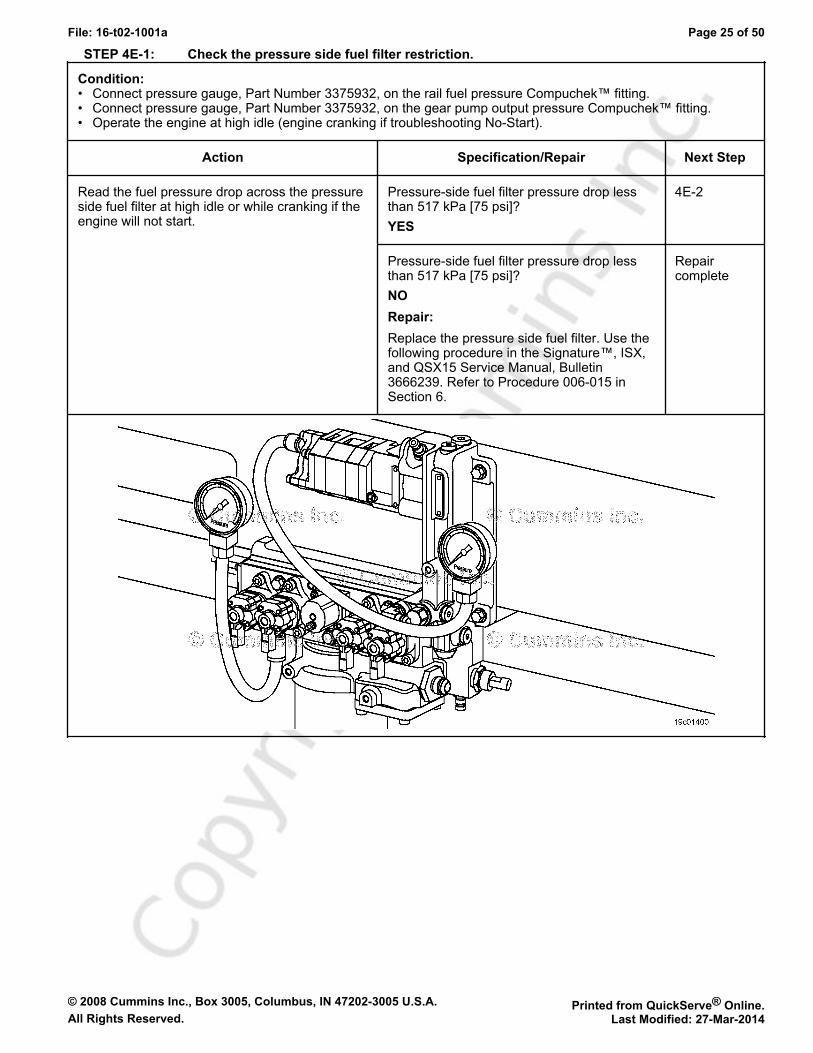
STEP 4E-1: Check the pressure side fuel filter restriction.
Condition:• Connect pressure gauge, Part Number 3375932, on the rail fuel pressure Compuchek™ fitting.• Connect pressure gauge, Part Number 3375932, on the gear pump output pressure Compuchek™ fitting.• Operate the engine at high idle (engine cranking if troubleshooting No-Start).
Action Specification/Repair Next Step
Read the fuel pressure drop across the pressureside fuel filter at high idle or while cranking if theengine will not start.
Pressure-side fuel filter pressure drop lessthan 517 kPa [75 psi]?YES
4E-2
Pressure-side fuel filter pressure drop lessthan 517 kPa [75 psi]?NORepair:Replace the pressure side fuel filter. Use thefollowing procedure in the Signature™, ISX,and QSX15 Service Manual, Bulletin3666239. Refer to Procedure 006-015 inSection 6.
Repaircomplete
© 2008 Cummins Inc., Box 3005, Columbus, IN 47202-3005 U.S.A. Printed from QuickServe® Online.All Rights Reserved. Last Modified: 27-Mar-2014
File: 16-t02-1001a Page 26 of 50
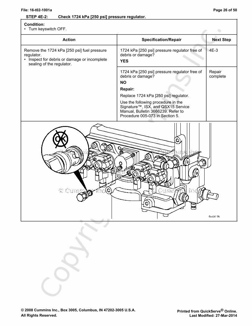
STEP 4E-2: Check 1724 kPa [250 psi] pressure regulator.
Condition:• Turn keyswitch OFF.
Action Specification/Repair Next Step
Remove the 1724 kPa [250 psi] fuel pressureregulator.• Inspect for debris or damage or incomplete
sealing of the regulator.
1724 kPa [250 psi] pressure regulator free ofdebris or damage?YES
4E-3
1724 kPa [250 psi] pressure regulator free ofdebris or damage?NORepair:Replace 1724 kPa [250 psi] regulator.Use the following procedure in theSignature™, ISX, and QSX15 ServiceManual, Bulletin 3666239. Refer toProcedure 005-073 in Section 5.
Repaircomplete
© 2008 Cummins Inc., Box 3005, Columbus, IN 47202-3005 U.S.A. Printed from QuickServe® Online.All Rights Reserved. Last Modified: 27-Mar-2014
File: 16-t02-1001a Page 27 of 50
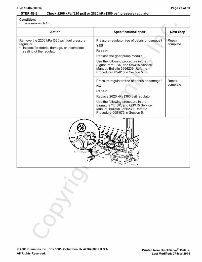
STEP 4E-3: Check 2206 kPa [320 psi] or 2620 kPa [380 psi] pressure regulator.
Condition:• Turn keyswitch OFF.
Action Specification/Repair Next Step
Remove the 2206 kPa [320 psi] fuel pressureregulator.• Inspect for debris, damage, or incomplete
sealing of the regulator.
Pressure regulator free of debris or damage?YESRepair:Replace the gear pump module.Use the following procedure in theSignature™, ISX, and QSX15 ServiceManual, Bulletin 3666239. Refer toProcedure 005-016 in Section 5.
Repaircomplete
Pressure regulator free of debris or damage?NORepair:Replace 2620 kPa [380 psi] regulator.Use the following procedure in theSignature™, ISX, and QSX15 ServiceManual, Bulletin 3666239. Refer toProcedure 005-073 in Section 5.
Repaircomplete
© 2008 Cummins Inc., Box 3005, Columbus, IN 47202-3005 U.S.A. Printed from QuickServe® Online.All Rights Reserved. Last Modified: 27-Mar-2014
File: 16-t02-1001a Page 28 of 50
STEP 5: Injector and Actuator Diagnostics.STEP 5A: Perform the Injector Check Valve Leak Test.
Condition:• -
Action Specification/Repair Next Step
Perform thePerform the Injector Check ValveLeak Test to check for internal injector checkvalve damage.Use the following procedure in the Signature™,ISX, and QSX15 Service Manual, Bulletin3666239. Refer to Procedure 006-026 in Section6.
Injector leak test detects a leaking injector?YESRepair:Replace the leaking injector. Use thefollowing procedure in the Signature™, ISX,and QSX15 Service Manual, Bulletin3666239. Refer to Procedure 006-026 inSection 6.
Repaircomplete
Injector leak test detects a leaking injector?NO
5B
STEP 5B: Perform INSITE™ electronic service tool Cylinder Performance Test.
Condition:• Troubleshoot any active fault codes before performing the test.• Note that engine coolant temperature must be greater than 83°C [180°F].• Connect INSITE™ electronic service tool.• Idle engine.
Action Specification/Repair Next Step
Perform the INSITE™ electronic service toolCylinder Performance Test.During the initial 30 seconds of the CylinderPerformance Test, INSITE™ electronic servicetool is checking to make sure all parametershave been met to enter the test.Once the initial Pass or Fail reading is displayed,the test is live for the next 2 minutes. Monitor thedisplay to see if cylinders or banks drop outduring this 2 minute window. A cylinder canswitch from pass to fail and back to pass quickly,so monitor the screen closely.
INSITE™ electronic service tool CylinderPerformance Test identifies a singlemalfunctioning injector?YES
5C-3
INSITE™ electronic service tool CylinderPerformance Test identifies a singlemalfunctioning injector?NO
5B-1

© 2008 Cummins Inc., Box 3005, Columbus, IN 47202-3005 U.S.A. Printed from QuickServe® Online.All Rights Reserved. Last Modified: 27-Mar-2014
File: 16-t02-1001a Page 29 of 50
STEP 5B-1: Perform INSITE™ electronic service tool Cylinder Performance Test at 600 rpm.
Condition:• Troubleshoot any active fault codes before performing the test.• Note that engine coolant temperature must be greater than 83°C [180°F].• Connect INSITE™ electronic service tool.• Idle engine at 600 rpm.
Action Specification/Repair Next Step
Skip this step and move on to step 5B-2 if therpm value is the same as that used in step 5B.Adjust the low speed to 600 rpm and performINSITE™ electronic service tool CylinderPerformance Test.During the initial 30 seconds of the CylinderPerformance Test, INSITE™ electronic servicetool is checking to make sure all parametershave been met to enter the test.Once the initial Pass or Fail reading is displayed,the test is live for the next 2 minutes. Monitor thedisplay to see if cylinders or banks drop outduring this 2 minute window. A cylinder canswitch from pass to fail and back to pass quickly,so monitor the screen closely.
INSITE™ electronic service tool CylinderPerformance Test identifies a singlemalfunctioning injector?YES
5C-3
INSITE™ electronic service tool CylinderPerformance Test identifies a singlemalfunctioning injector?NO
5B-2
STEP 5B-2: Perform INSITE™ electronic service tool Cylinder Performance Test at 700 rpm.
Condition:• Troubleshoot any active fault codes before performing the test.• Note that engine coolant temperature must be greater than 83°C [180°F].• Connect INSITE™ electronic service tool.• Idle engine at 700 rpm.The idle speed may need to be adjusted to perform this test. Toggle the cruise control increment/decrement switchto see if the idle speed can be adjusted. If not, use INSITE™ electronic service tool to either enable the AdjustableLow Idle Speed feature or adjust the Low Idle Speed.
Action Specification/Repair Next Step
Skip this step and move on to step 5B-3 if theRPM value is the same as that used in step 5B.Adjust the low speed to 700 rpm and performINSITE™ electronic service tool CylinderPerformance Test.During the initial 30 seconds of the CylinderPerformance Test, INSITE™ electronic servicetool is checking to make sure all parametershave been met to enter the test.Once the initial Pass or Fail reading is displayed,the test is live for the next 2 minutes. Monitor thedisplay to see if cylinders or banks drop outduring this 2 minute window. A cylinder canswitch from pass to fail and back to pass quickly,so monitor the screen closely.
INSITE™ electronic service tool CylinderPerformance Test identifies a singlemalfunctioning injector?YES
5C-3
INSITE™ electronic service tool CylinderPerformance Test identifies a singlemalfunctioning injector?NO
5B-3
© 2008 Cummins Inc., Box 3005, Columbus, IN 47202-3005 U.S.A. Printed from QuickServe® Online.All Rights Reserved. Last Modified: 27-Mar-2014
File: 16-t02-1001a Page 30 of 50
STEP 5B-3: Perform INSITE™ electronic service tool Cylinder Performance Test at 800 rpm.
Condition:• Troubleshoot any active fault codes before performing the test.• Note that engine coolant temperature must be greater than 83°C [180°F].• Connect INSITE™ electronic service tool.• Idle engine at 800 rpm.The idle speed may need to be adjusted to perform this test. Toggle the cruise control increment/decrement switchto see if the idle speed can be adjusted. If not, use INSITE™ electronic service tool to either enable the"Adjustable Low Idle Speed" feature or adjust the Low Idle Speed.
Action Specification/Repair Next Step
Skip this step and move on to step 5C if the rpmvalue is the same as that used in step 5B.Adjust the low speed to 800 rpm and performINSITE™ electronic service tool CylinderPerformance Test.During the initial 30 seconds of the CylinderPerformance Test, INSITE™ electronic servicetool is checking to make sure all parametershave been met to enter the test.Once the initial Pass or Fail reading is displayed,the test is live for the next 2 minutes. Monitor thedisplay to see if cylinders or banks drop outduring this 2 minute window. A cylinder canswitch from pass to fail and back to pass quickly,so monitor the screen closely.
INSITE™ electronic service tool CylinderPerformance Test identifies a singlemalfunctioning injector?YES
5C-3
INSITE™ electronic service tool CylinderPerformance Test identifies a singlemalfunctioning injector?NO
5C
STEP 5C: Perform INSITE™ electronic service tool Cylinder Cutout Test
Condition:• Turn air conditioning OFF.• Turn fan OFF.• Disable any electrical loads.• Idle engine at the engine speed at which the misfire is present.
Action Specification/Repair Next Step
Perform INSITE™ electronic service tool cylindercutout test.A failing cylinder will have no effect on enginesound and operation when cut out using this test.
All cylinders pass the cylinder cutout test?YES
5C-1
All cylinders pass the cylinder cutout test?NO
5C-3
© 2008 Cummins Inc., Box 3005, Columbus, IN 47202-3005 U.S.A. Printed from QuickServe® Online.All Rights Reserved. Last Modified: 27-Mar-2014
File: 16-t02-1001a Page 31 of 50
STEP 5C-1: Perform INSITE™ electronic service tool Cylinder Cutout Test on individual injector banks.
Condition:• Turn air conditioning OFF.• Turn fan OFF.• Disable any electrical loads.• Engine idling at the engine speed at which the misfire is present.
Action Specification/Repair Next Step
Perform INSITE™ electronic service toolCylinder Cutout Test.• Operate the engine on the front bank of
injectors identified by the cylinder cutout testby disabling the rear three cylinders 4, 5, 6cylinders with INSITE™ electronic service tool.
• Operate the engine on the rear bank ofinjectors identified by the CylinderPerformance Test by disabling the front threecylinders (1,2,3) with INSITE™ electronicservice tool.
• To disable one bank of cylinders withINSITE™ electronic service tool, click on thecylinder numbers associated with that bank.The front bank consists of cylinders 1, 2, and 3and the rear bank is cylinders 4, 5, and 6.
• A malfunctioning bank of injectors will causethe engine to run poorly when the oppositebank is cut out using this test.
Malfunctioning bank of injectors isolated byoperating the engine on either bank ofinjectors?YES
5D
Malfunctioning bank of injectors isolated byoperating the engine on either bank ofinjectors?NO
5C-2
© 2008 Cummins Inc., Box 3005, Columbus, IN 47202-3005 U.S.A. Printed from QuickServe® Online.All Rights Reserved. Last Modified: 27-Mar-2014
File: 16-t02-1001a Page 32 of 50
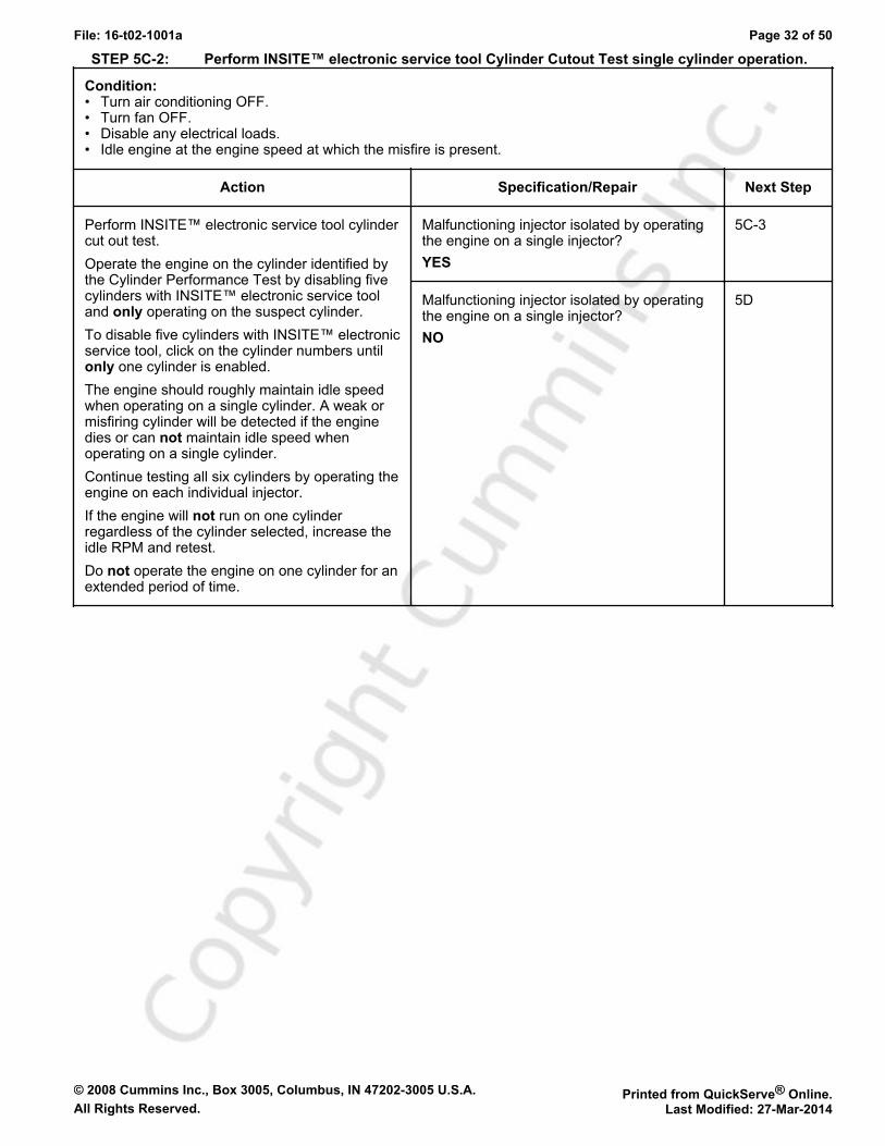
STEP 5C-2: Perform INSITE™ electronic service tool Cylinder Cutout Test single cylinder operation.
Condition:• Turn air conditioning OFF.• Turn fan OFF.• Disable any electrical loads.• Idle engine at the engine speed at which the misfire is present.
Action Specification/Repair Next Step
Perform INSITE™ electronic service tool cylindercut out test.Operate the engine on the cylinder identified bythe Cylinder Performance Test by disabling fivecylinders with INSITE™ electronic service tooland only operating on the suspect cylinder.To disable five cylinders with INSITE™ electronicservice tool, click on the cylinder numbers untilonly one cylinder is enabled.The engine should roughly maintain idle speedwhen operating on a single cylinder. A weak ormisfiring cylinder will be detected if the enginedies or can not maintain idle speed whenoperating on a single cylinder.Continue testing all six cylinders by operating theengine on each individual injector.If the engine will not run on one cylinderregardless of the cylinder selected, increase theidle RPM and retest.Do not operate the engine on one cylinder for anextended period of time.
Malfunctioning injector isolated by operatingthe engine on a single injector?YES
5C-3
Malfunctioning injector isolated by operatingthe engine on a single injector?NO
5D
© 2008 Cummins Inc., Box 3005, Columbus, IN 47202-3005 U.S.A. Printed from QuickServe® Online.All Rights Reserved. Last Modified: 27-Mar-2014
File: 16-t02-1001a Page 33 of 50
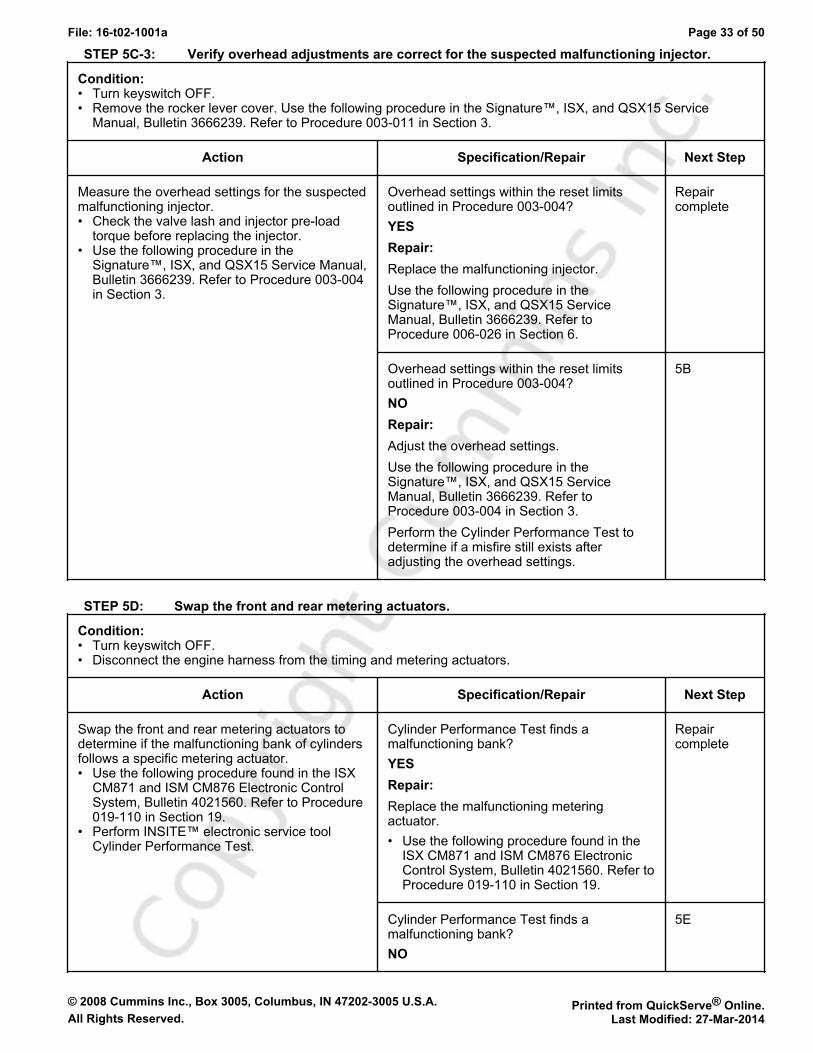
STEP 5C-3: Verify overhead adjustments are correct for the suspected malfunctioning injector.
Condition:• Turn keyswitch OFF.• Remove the rocker lever cover. Use the following procedure in the Signature™, ISX, and QSX15 Service
Manual, Bulletin 3666239. Refer to Procedure 003-011 in Section 3.
Action Specification/Repair Next Step
Measure the overhead settings for the suspectedmalfunctioning injector.• Check the valve lash and injector pre-load
torque before replacing the injector.• Use the following procedure in the
Signature™, ISX, and QSX15 Service Manual,Bulletin 3666239. Refer to Procedure 003-004in Section 3.
Overhead settings within the reset limitsoutlined in Procedure 003-004?YESRepair:Replace the malfunctioning injector.Use the following procedure in theSignature™, ISX, and QSX15 ServiceManual, Bulletin 3666239. Refer toProcedure 006-026 in Section 6.
Repaircomplete
Overhead settings within the reset limitsoutlined in Procedure 003-004?NORepair:Adjust the overhead settings.Use the following procedure in theSignature™, ISX, and QSX15 ServiceManual, Bulletin 3666239. Refer toProcedure 003-004 in Section 3.Perform the Cylinder Performance Test todetermine if a misfire still exists afteradjusting the overhead settings.
5B
STEP 5D: Swap the front and rear metering actuators.
Condition:• Turn keyswitch OFF.• Disconnect the engine harness from the timing and metering actuators.
Action Specification/Repair Next Step
Swap the front and rear metering actuators todetermine if the malfunctioning bank of cylindersfollows a specific metering actuator.• Use the following procedure found in the ISX
CM871 and ISM CM876 Electronic ControlSystem, Bulletin 4021560. Refer to Procedure019-110 in Section 19.
• Perform INSITE™ electronic service toolCylinder Performance Test.
Cylinder Performance Test finds amalfunctioning bank?YESRepair:Replace the malfunctioning meteringactuator.• Use the following procedure found in the
ISX CM871 and ISM CM876 ElectronicControl System, Bulletin 4021560. Refer toProcedure 019-110 in Section 19.
Repaircomplete
Cylinder Performance Test finds amalfunctioning bank?NO
5E
© 2008 Cummins Inc., Box 3005, Columbus, IN 47202-3005 U.S.A. Printed from QuickServe® Online.All Rights Reserved. Last Modified: 27-Mar-2014
File: 16-t02-1001a Page 34 of 50
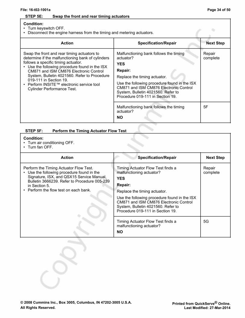
STEP 5E: Swap the front and rear timing actuators
Condition:• Turn keyswitch OFF.• Disconnect the engine harness from the timing and metering actuators.
Action Specification/Repair Next Step
Swap the front and rear timing actuators todetermine if the malfunctioning bank of cylindersfollows a specific timing actuator.• Use the following procedure found in the ISX
CM871 and ISM CM876 Electronic ControlSystem, Bulletin 4021560. Refer to Procedure019-111 in Section 19.
• Perform INSITE™ electronic service toolCylinder Performance Test.
Malfunctioning bank follows the timingactuator?YESRepair:Replace the timing actuator.Use the following procedure found in the ISXCM871 and ISM CM876 Electronic ControlSystem, Bulletin 4021560. Refer toProcedure 019-111 in Section 19.
Repaircomplete
Malfunctioning bank follows the timingactuator?NO
5F
STEP 5F: Perform the Timing Actuator Flow Test
Condition:• Turn air conditioning OFF.• Turn fan OFF.
Action Specification/Repair Next Step
Perform the Timing Actuator Flow Test.• Use the following procedure found in the
Signature, ISX, and QSX15 Service Manual,Bulletin 3666239. Refer to Procedure 005-239in Section 5.
• Perform the flow test on each bank.
Timing Actuator Flow Test finds amalfunctioning actuator?YESRepair:Replace the timing actuator.Use the following procedure found in the ISXCM871 and ISM CM876 Electronic ControlSystem, Bulletin 4021560. Refer toProcedure 019-111 in Section 19.
Repaircomplete
Timing Actuator Flow Test finds amalfunctioning actuator?NO
5G
© 2008 Cummins Inc., Box 3005, Columbus, IN 47202-3005 U.S.A. Printed from QuickServe® Online.All Rights Reserved. Last Modified: 27-Mar-2014
File: 16-t02-1001a Page 35 of 50
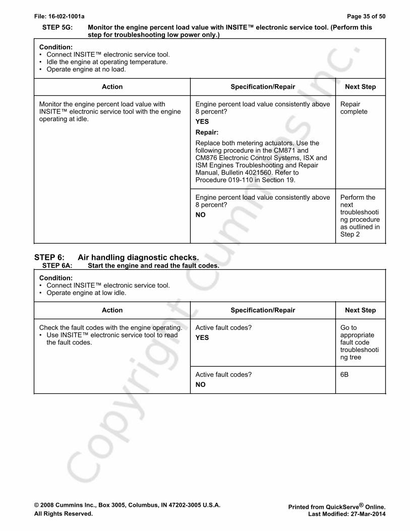
STEP 5G: Monitor the engine percent load value with INSITE™ electronic service tool. (Perform thisstep for troubleshooting low power only.)
Condition:• Connect INSITE™ electronic service tool.• Idle the engine at operating temperature.• Operate engine at no load.
Action Specification/Repair Next Step
Monitor the engine percent load value withINSITE™ electronic service tool with the engineoperating at idle.
Engine percent load value consistently above8 percent?YESRepair:Replace both metering actuators. Use thefollowing procedure in the CM871 andCM876 Electronic Control Systems, ISX andISM Engines Troubleshooting and RepairManual, Bulletin 4021560. Refer toProcedure 019-110 in Section 19.
Repaircomplete
Engine percent load value consistently above8 percent?NO
Perform thenexttroubleshooting procedureas outlined inStep 2
STEP 6: Air handling diagnostic checks.STEP 6A: Start the engine and read the fault codes.
Condition:• Connect INSITE™ electronic service tool.• Operate engine at low idle.
Action Specification/Repair Next Step
Check the fault codes with the engine operating.• Use INSITE™ electronic service tool to read
the fault codes.
Active fault codes?YES
Go toappropriatefault codetroubleshooting tree
Active fault codes?NO
6B
© 2008 Cummins Inc., Box 3005, Columbus, IN 47202-3005 U.S.A. Printed from QuickServe® Online.All Rights Reserved. Last Modified: 27-Mar-2014
File: 16-t02-1001a Page 36 of 50
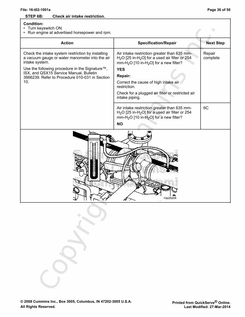
STEP 6B: Check air intake restriction.
Condition:• Turn keyswitch ON.• Run engine at advertised horsepower and rpm.
Action Specification/Repair Next Step
Check the intake system restriction by installinga vacuum gauge or water manometer into the airintake system.Use the following procedure in the Signature™,ISX, and QSX15 Service Manual, Bulletin3666239. Refer to Procedure 010-031 in Section10.
Air intake restriction greater than 635 mm-H2O [25 in-H2O] for a used air filter or 254mm-H2O [10 in-H2O] for a new filter?YESRepair:Correct the cause of high intake airrestriction.Check for a plugged air filter or restricted airintake piping.
Repaircomplete
Air intake restriction greater than 635 mm-H2O [25 in-H2O] for a used air filter or 254mm-H2O [10 in-H2O] for a new filter?NO
6C
© 2008 Cummins Inc., Box 3005, Columbus, IN 47202-3005 U.S.A. Printed from QuickServe® Online.All Rights Reserved. Last Modified: 27-Mar-2014
File: 16-t02-1001a Page 37 of 50
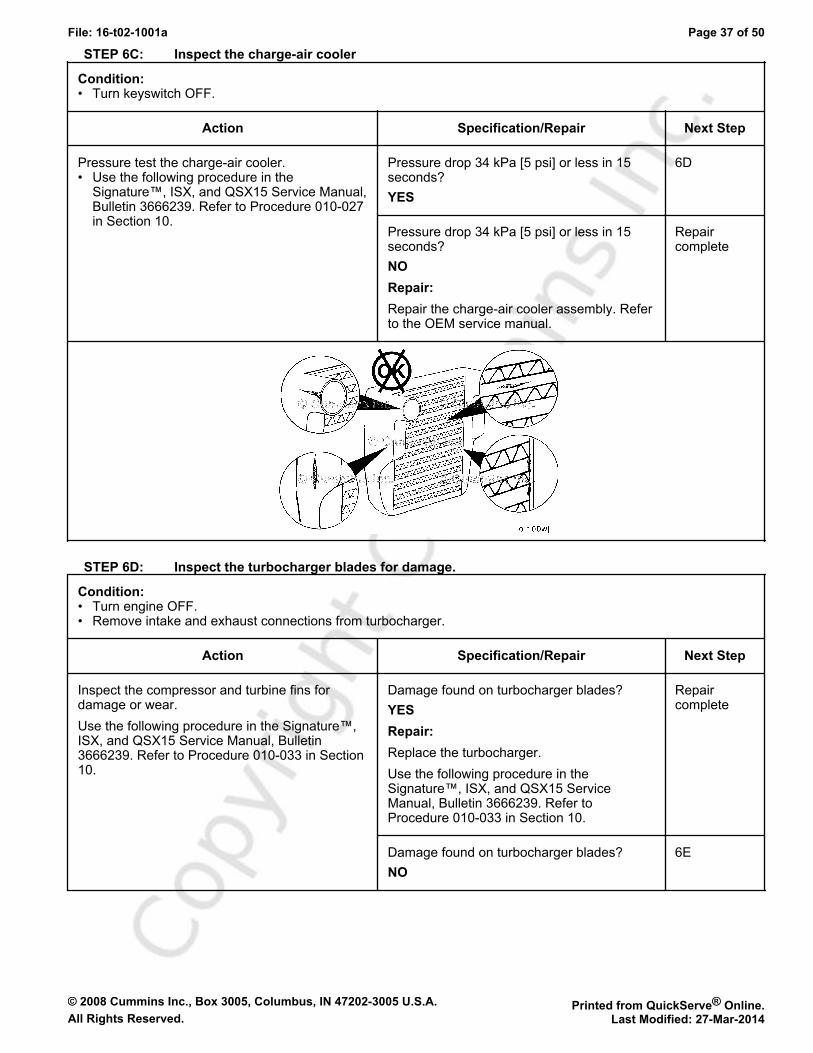
STEP 6C: Inspect the charge-air cooler
Condition:• Turn keyswitch OFF.
Action Specification/Repair Next Step
Pressure test the charge-air cooler.• Use the following procedure in the
Signature™, ISX, and QSX15 Service Manual,Bulletin 3666239. Refer to Procedure 010-027in Section 10.
Pressure drop 34 kPa [5 psi] or less in 15seconds?YES
6D
Pressure drop 34 kPa [5 psi] or less in 15seconds?NORepair:Repair the charge-air cooler assembly. Referto the OEM service manual.
Repaircomplete
STEP 6D: Inspect the turbocharger blades for damage.
Condition:• Turn engine OFF.• Remove intake and exhaust connections from turbocharger.
Action Specification/Repair Next Step
Inspect the compressor and turbine fins fordamage or wear.Use the following procedure in the Signature™,ISX, and QSX15 Service Manual, Bulletin3666239. Refer to Procedure 010-033 in Section10.
Damage found on turbocharger blades?YESRepair:Replace the turbocharger.Use the following procedure in theSignature™, ISX, and QSX15 ServiceManual, Bulletin 3666239. Refer toProcedure 010-033 in Section 10.
Repaircomplete
Damage found on turbocharger blades?NO
6E
© 2008 Cummins Inc., Box 3005, Columbus, IN 47202-3005 U.S.A. Printed from QuickServe® Online.All Rights Reserved. Last Modified: 27-Mar-2014
File: 16-t02-1001a Page 38 of 50
STEP 6E: Inspect the turbocharger shaft movement.
Condition:• Turn keyswitch OFF.• Remove VGT actuator from the turbocharger.
Action Specification/Repair Next Step
Inspect the sector gear on the turbocharger fordamaged or broken gear teeth.Move the sector gear lever on the turbochargerbearing housing up and down from stop to stop.Check for smooth movement between the stops.There will be an initial friction force that must beovercome before the actuator lever will move.Once movement is started, the actuator levershould move to the other stop position by hand.Use the following procedure in the Signature™,ISX and QSX15 Service Manual, Bulletin3666239. Refer to Procedure 010-134 in Section10.
Nozzle slides evenly from stop to stop andgear teeth undamaged?YESRepair:Install the turbocharger actuator.Use the following procedure in theSignature™, ISX and QSX15 ServiceManual, Bulletin 3666239. Refer toProcedure 010-134 in Section 10.
Perform thenexttroubleshooting procedureas outlined inStep 2.
Nozzle slides evenly from stop to stop andgear teeth undamaged?NORepair:A turbocharger mechanical malfunction hasbeen detected.Inspect the turbocharger for repair andreuse, if possible. Use the followingprocedure in the Signature™, ISX andQSX15 Service Manual, Bulletin 3666239.Refer to Procedure 010-145 in Section 10.
Repaircomplete
STEP 7: Check EGR valve for proper operation.STEP 7A: Check for EGR-related fault codes
Condition:• Turn keyswitch OFF.• Wait 30 seconds.• Turn keyswitch ON.• Connect INSITE™ electronic service tool.
Action Specification/Repair Next Step
Check for any EGR-related fault codes. EGR-related fault codes present?YESRepair:Troubleshoot electronic fault codes.
Appropriatefault codetroubleshooting trees
EGR-related fault codes present?NO
7B

© 2008 Cummins Inc., Box 3005, Columbus, IN 47202-3005 U.S.A. Printed from QuickServe® Online.All Rights Reserved. Last Modified: 27-Mar-2014
File: 16-t02-1001a Page 39 of 50
STEP 7B: Check for inactive EGR differential pressure sensor fault codes.
Condition:• Turn keyswitch ON.• Connect INSITE™ electronic service tool.
Action Specification/Repair Next Step
Check for active fault codes.• Use INSITE™ electronic service tool to read
the fault codes.
Fault Code 1866, 2273, or 2274 active?YES
Appropriatefault codetroubleshooting tree
Fault Code 1866, 2273, or 2274 active?NO
7C
STEP 7C: Check the EGR differential pressure tubes for leaks.
Condition:• Note leaks by traces of soot.
Action Specification/Repair Next Step
Check the lines for leaks. Leaks detected at either the low or high EGRdifferential pressure tubes?YESRepair:Tighten the fittings or replace the EGRdifferential pressure tube.Use the following procedure in theSignature™, ISX, and QSX15 ServiceManual, Bulletin 3666239. Refer toProcedure 011-026 in Section 11.
Repaircomplete
Leaks detected at either the low or high EGRdifferential pressure tubes?NO
7D
© 2008 Cummins Inc., Box 3005, Columbus, IN 47202-3005 U.S.A. Printed from QuickServe® Online.All Rights Reserved. Last Modified: 27-Mar-2014
File: 16-t02-1001a Page 40 of 50
STEP 7D: Check the EGR differential pressure sensor adapter for leaks.
Condition:• Turn keyswitch OFF.
Action Specification/Repair Next Step
Inspect the EGR differential pressure sensoradapter for leaks.• Leaks will be easily noted by traces of soot. If
necessary remove the sensor to inspect the o-rings between the EGR differential pressuresensor and the adapter for proper sealing. Usethe following procedure in the Signature™,ISX, and QSX15 Service Manual, Bulletin3666239. Refer to Procedure 011-028 inSection 11.
Leaks detected at the EGR differentialpressure sensor adapter?YESRepair:Replace the EGR differential pressuresensor adapter.Use the following procedure in theSignature™, ISX, and QSX15 ServiceManual, Bulletin 3666239. Refer toProcedure 011-028 in Section 11.
Repaircomplete
Leaks detected at the EGR differentialpressure sensor adapter?NO
7E
STEP 7E: Check the EGR differential pressure tubes for plugging.
Condition:• Turn keyswitch OFF.• Remove the EGR differential pressure tubes.
Action Specification/Repair Next Step
Inspect the EGR differential pressure tubes forrestrictions, soot plugging, and plugging.
Debris or soot found in either EGRdifferential pressure tube?YESRepair:Clear the debris or replace the EGRdifferential pressure tube.• Use the following procedure in the
Signature™, ISX, and QSX15 ServiceManual, Bulletin 3666239. Refer toProcedure 011-026 in Section 11.
Remove the exhaust aftertreatment systemfrom the vehicle and inspect for reuse.• Use the following procedure in the
Signature™, ISX, and QSX15 ServiceManual, Bulletin 3666239. Refer toProcedure 011-050 in Section 11.
Repaircomplete
Debris or soot found in either EGRdifferential pressure tube?NO
7F
© 2008 Cummins Inc., Box 3005, Columbus, IN 47202-3005 U.S.A. Printed from QuickServe® Online.All Rights Reserved. Last Modified: 27-Mar-2014
File: 16-t02-1001a Page 41 of 50
STEP 7F: Check for air leaks in the EGR system.
Condition:
Action Specification/Repair Next Step
Check for leaks in the EGR connection tubingand connections.Soot streaks are noticeable where leaks arepresent.
Leaks found in the EGR connection tubing?YESRepair:Repair any leaks in the EGR system.
Repaircomplete
Leaks found in the EGR connection tubing?NO
Perform thenexttroubleshooting procedureas outlined inStep 2
STEP 8: Verify electronic features operating correctly.STEP 8A: Verify accelerator pedal travel.
Condition:• Turn keyswitch ON.• Connect INSITE™ electronic service tool.
Action Specification/Repair Next Step
With INSITE™ electronic service tool, monitoraccelerator pedal while fully depressing andreleasing the accelerator pedal.
Accelerator pedal reads 0 percent when theaccelerator is released and 100 percentwhen the accelerator is depressed?YES
8B
Accelerator pedal reads 0 percent when theaccelerator is released and 100 percentwhen the accelerator is depressed?NORepair:Determine and correct the cause ofaccelerator pedal restriction.
Repaircomplete
© 2008 Cummins Inc., Box 3005, Columbus, IN 47202-3005 U.S.A. Printed from QuickServe® Online.All Rights Reserved. Last Modified: 27-Mar-2014
File: 16-t02-1001a Page 42 of 50
STEP 8B: Monitor vehicle speed.
Condition:• Turn keyswitch ON.• Connect INSITE™ electronic service tool.• Start the engine.
Action Specification/Repair Next Step
With INSITE™ electronic service tool, monitorvehicle speed while the vehicle is not moving.
Vehicle speed reads 0 when the vehicle isnot moving?YES
8C
Vehicle speed reads 0 when the vehicle isnot moving?NORepair:Check the vehicle speed sensor and circuitor locate the cause of the vehicle speedinterference.
Repaircomplete
STEP 8C: Verify electronic feature settings are correct.
Condition:• Turn keyswitch ON.• Connect INSITE™ electronic service tool.
Action Specification/Repair Next Step
With INSITE™ electronic service tool, verify thefollowing adjustable parameters are correctly set:• Maximum vehicle speed• Powertrain protection• Rear axle ratio• Number of transmission tailshaft gear teeth• Tire revolutions per mile• Gear-down protection• Cruise control droop settings• Cruise control maximum vehicle speed.
Electronic features set correctly?YES
8D
Electronic features set correctly?NORepair:Correct programmable features.
Repaircomplete

© 2008 Cummins Inc., Box 3005, Columbus, IN 47202-3005 U.S.A. Printed from QuickServe® Online.All Rights Reserved. Last Modified: 27-Mar-2014
File: 16-t02-1001a Page 43 of 50
STEP 8D: Check the intake manifold pressure sensor accuracy.
Condition:• Turn keyswitch ON.• Connect INSITE™ electronic service tool.• Start and operate the engine at high idle after connecting the mechanical intake manifold pressure gauge.
Action Specification/Repair Next Step
Connect a mechanical intake manifold pressuregauge to the engine, as close to the intakemanifold pressure sensor as possible.• Start INSITE™ electronic service tool Data
Monitor/Logger and compare INSITE™electronic service tool reading for intakemanifold pressure to the mechanical gauge.
INSITE™ electronic service tool readingwithin 17 kPa [2.5 psi] of mechanical gaugereading?YES
Perform thenexttroubleshooting procedureas outlined inStep 2
INSITE™ electronic service tool readingwithin 17 kPa [2.5 psi] of mechanical gaugereading?NORepair:Remove and clean the intake manifoldpressure sensor.Use the following procedure found in the ISXCM871 and ISM CM876 Electronic ControlSystem, Bulletin 4021560. Refer toProcedure 019-159 in Section 19.
Repaircomplete
STEP 9: Perform base engine mechanical checks.STEP 9A: Verify injection timing is correct.
Condition:• Turn keyswitch OFF.• Remove valve cover.
Action Specification/Repair Next Step
Verify injection timing is correct.Measure the injection timing. Use the followingprocedure in the Signature™, ISX, and QSX15Service Manual, Bulletin 3666239. Refer toProcedure 006-025 in Section 6.If the injection timing is found to be out ofspecification, bar the engine to "insert pin" andinstall the crankshaft pin. Install the appropriateinjector camshaft wedge to set the correctinjection timing. Use the following procedure inthe Signature™, ISX, and QSX15 ServiceManual, Bulletin 3666239. Refer to Procedure001-088 in Section 1.
Injection timing correct?YES
9B
Injection timing correct?NORepair:Correct the injection timing.Use the following procedure in theSignature™, ISX, and QSX15 ServiceManual, Bulletin 3666239. Refer toProcedure 001-088 in Section 1.
Repaircomplete
© 2008 Cummins Inc., Box 3005, Columbus, IN 47202-3005 U.S.A. Printed from QuickServe® Online.All Rights Reserved. Last Modified: 27-Mar-2014
File: 16-t02-1001a Page 44 of 50
STEP 9B: Verify overhead adjustments are correct.
Condition:• Turn keyswitch OFF.• Remove valve cover.
Action Specification/Repair Next Step
Measure the overhead settings.Use the following procedure in the Signature™,ISX, and QSX15 Service Manual, Bulletin3666239. Refer to Procedure 003-004 in Section3.
Overhead settings within the reset limits?YES
9C
Overhead settings within the reset limits?NORepair:Adjust the overhead settings.Use the following procedure in theSignature™, ISX, and QSX15 ServiceManual, Bulletin 3666239. Refer toProcedure 003-004 in Section 3.
Repaircomplete
STEP 9C: Verify engine brake adjustment.
Condition:• Turn keyswitch OFF.• Remove valve cover.
Action Specification/Repair Next Step
Verify the engine brakes are operating correctly.• Measure the engine brake settings. Use the
following procedure in the Signature™, ISX,and QSX15 Service Manual, Bulletin 3666239.Refer to Procedure 020-004 in Section 20.
Engine brake settings within the reset limits?YES
9D
Engine brake settings within the reset limits?NORepair:Adjust the engine brake settings.Use the following procedure in theSignature™, ISX, and QSX15 ServiceManual, Bulletin 3666239. Refer toProcedure 020-004 in Section 20.
Repaircomplete

© 2008 Cummins Inc., Box 3005, Columbus, IN 47202-3005 U.S.A. Printed from QuickServe® Online.All Rights Reserved. Last Modified: 27-Mar-2014
File: 16-t02-1001a Page 45 of 50
STEP 9D: Verify crankshaft tone wheel is not loose.
Condition:• Unplug the crankshaft position sensor.• Operate the engine at idle.
Action Specification/Repair Next Step
Operate the engine with the crankshaft positionsensor unplugged and identify if idle qualityimproves.• If idle quality improves, remove the oil pan and
inspect the crankshaft tone wheel to see if it isloose.
Crankshaft tone wheel loose?YESRepair:Repair the tone wheel.Use the following procedure in theSignature™, ISX, and QSX15 ServiceManual, Bulletin 3666239. Refer toProcedure 001-069 in Section 1.
Repaircomplete
Crankshaft tone wheel loose?NO
9E
© 2008 Cummins Inc., Box 3005, Columbus, IN 47202-3005 U.S.A. Printed from QuickServe® Online.All Rights Reserved. Last Modified: 27-Mar-2014
File: 16-t02-1001a Page 46 of 50
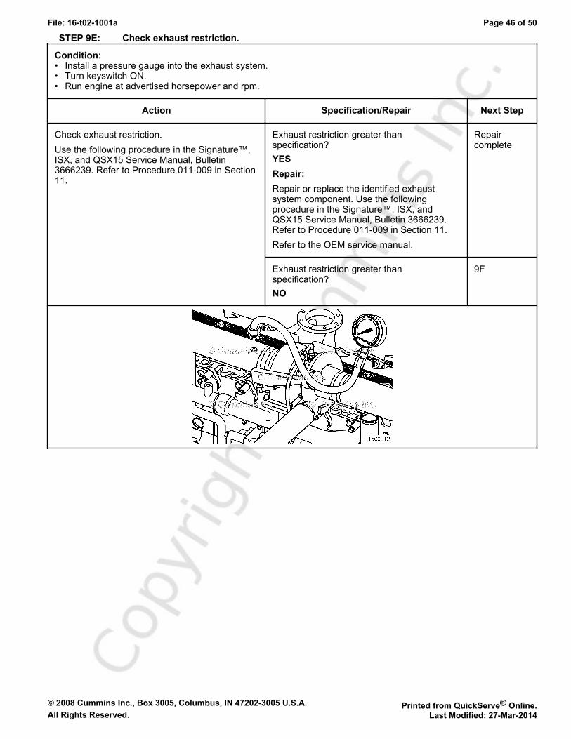
STEP 9E: Check exhaust restriction.
Condition:• Install a pressure gauge into the exhaust system.• Turn keyswitch ON.• Run engine at advertised horsepower and rpm.
Action Specification/Repair Next Step
Check exhaust restriction.Use the following procedure in the Signature™,ISX, and QSX15 Service Manual, Bulletin3666239. Refer to Procedure 011-009 in Section11.
Exhaust restriction greater thanspecification?YESRepair:Repair or replace the identified exhaustsystem component. Use the followingprocedure in the Signature™, ISX, andQSX15 Service Manual, Bulletin 3666239.Refer to Procedure 011-009 in Section 11.Refer to the OEM service manual.
Repaircomplete
Exhaust restriction greater thanspecification?NO
9F

© 2008 Cummins Inc., Box 3005, Columbus, IN 47202-3005 U.S.A. Printed from QuickServe® Online.All Rights Reserved. Last Modified: 27-Mar-2014
File: 16-t02-1001a Page 47 of 50
STEP 9F: Verify engine blowby is within specification.
Condition:• Turn keyswitch OFF.• Connect the appropriate orifice to the end of the blowby draft tube.• Start engine.
Action Specification/Repair Next Step
Load engine to rated rpm on a chassisdynamometer.Measure the engine blowby.Use the following procedure in the Signature™,ISX, and QSX15 Service Manual, Bulletin3666239. Refer to Procedure 014-010 in Section14.
Engine blowby measurements withinspecification?YES
Perform thenexttroubleshooting procedureas outlined inStep 2
Engine blowby measurements withinspecification?NORepair:Engine may need to be rebuilt. See theengine specifications.
Repaircomplete
STEP 10: Aftertreatment checks.STEP 10A: Check for aftertreatment-related fault codes.
Condition:• Turn keyswitch OFF.• Connect INSITE™ electronic service tool.
Action Specification/Repair Next Step
Use INSITE™ electronic service tool to read thefault codes.Check for any aftertreatment fault codes,specifically fault codes related to high soot in theaftertreatment particulate trap, face plugging ofthe aftertreatment catalyst, and aftertreatmentcatalyst efficiency.
Fault codes related to the aftertreatmentsystem found to be active?YES
Appropriatefault codetroubleshooting tree
Fault codes related to the aftertreatmentsystem found to be active?NO
10B

© 2008 Cummins Inc., Box 3005, Columbus, IN 47202-3005 U.S.A. Printed from QuickServe® Online.All Rights Reserved. Last Modified: 27-Mar-2014
File: 16-t02-1001a Page 48 of 50
STEP 10B: Perform basic aftertreatment troubleshooting checks.
Condition:• -
Action Specification/Repair Next Step
The following items must be checked or verifiedbefore continuing:• Check to make sure that Ultra Low Sulfur
Diesel fuel is being used in the vehicle.• Check for any fuel leaks around the
aftertreatment fuel shutoff valve oraftertreatment injector components.
• Check for any noticeable exhaust leaksaround any aftertreatment components.
• Check the exhaust pipes for restrictions thatcan create high exhaust back pressure.
• Check the aftertreatment sensors, wires,connectors, and harnesses for properconnections.
• Check the exhaust gas filter differentialpressure sensor tubes for proper connections.
All parts inspected and appear to befunctioning properly?YES
10C
All parts inspected and appear to befunctioning properly?NORepair:Correct the damage and verify the complaintis no longer present after repair.
Repaircomplete
STEP 10C: Check for signs of internal damage to the aftertreatment system.
Condition:• Operate engine to normal operating temperature.• Be sure the vehicle is stationary.
Action Specification/Repair Next Step
Quickly snap the throttle pedal accelerating theengine from low idle to high idle while checkingfor smoke at the exhaust outlet.Inspect for the following during the Snap ThrottleAcceleration Test.• Smoke (any color) coming out of the vehicle
tailpipe.• Soot or signs of fuel, coolant, or oil inside the
tailpipe.If the aftertreatment system is operatingcorrectly, no visible smoke will be present duringsnap throttle acceleration. Any visible smoke isan indication of a possible malfunction in theaftertreatment system.
Visible smoke (black or white) present duringthe Snap Throttle Acceleration Test?YESRepair:Damage in the aftertreatment system.Remove the exhaust gas aftertreatmentsystem from the vehicle and inspect forreuse.Use the following procedure in theSignature™, ISX, and QSX15 ServiceManual, Bulletin 3666239. Refer toProcedure 011-050 in Section 11.
Repaircomplete.Troubleshootthe smokecomplaint,use theproper TTtree steps
Visible smoke (black or white) present duringthe Snap Throttle Acceleration Test?NO
10D
© 2008 Cummins Inc., Box 3005, Columbus, IN 47202-3005 U.S.A. Printed from QuickServe® Online.All Rights Reserved. Last Modified: 27-Mar-2014
File: 16-t02-1001a Page 49 of 50
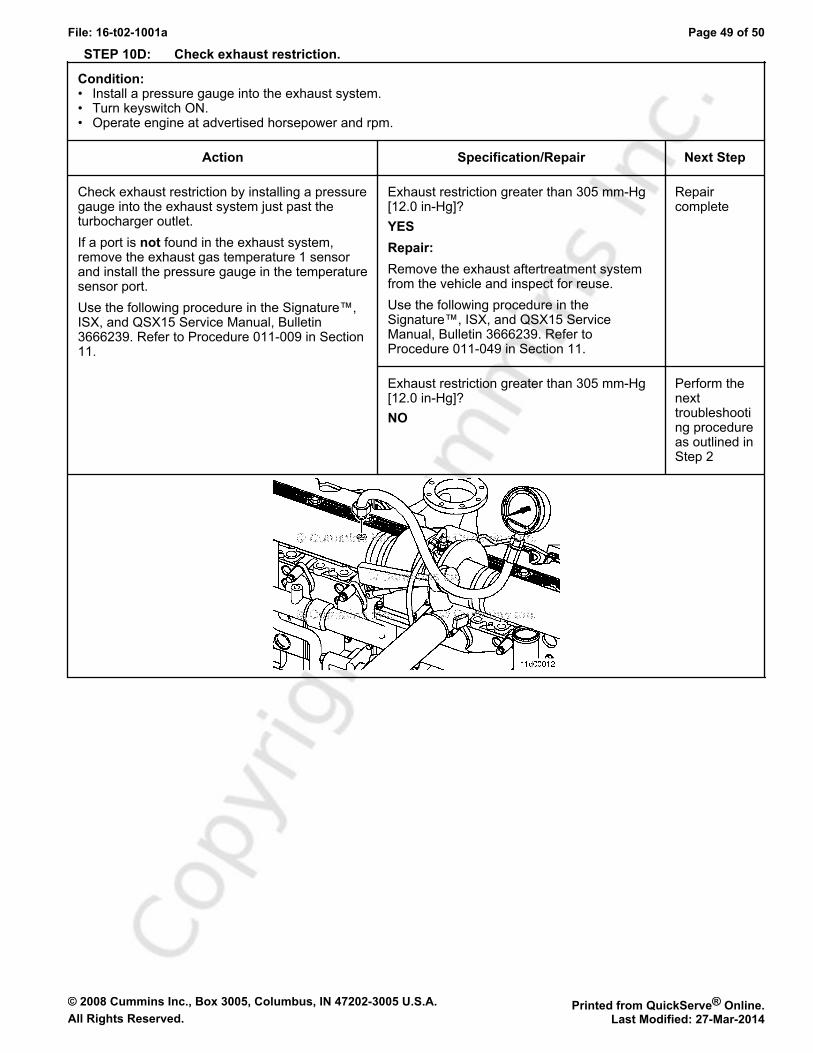
STEP 10D: Check exhaust restriction.
Condition:• Install a pressure gauge into the exhaust system.• Turn keyswitch ON.• Operate engine at advertised horsepower and rpm.
Action Specification/Repair Next Step
Check exhaust restriction by installing a pressuregauge into the exhaust system just past theturbocharger outlet.If a port is not found in the exhaust system,remove the exhaust gas temperature 1 sensorand install the pressure gauge in the temperaturesensor port.Use the following procedure in the Signature™,ISX, and QSX15 Service Manual, Bulletin3666239. Refer to Procedure 011-009 in Section11.
Exhaust restriction greater than 305 mm-Hg[12.0 in-Hg]?YESRepair:Remove the exhaust aftertreatment systemfrom the vehicle and inspect for reuse.Use the following procedure in theSignature™, ISX, and QSX15 ServiceManual, Bulletin 3666239. Refer toProcedure 011-049 in Section 11.
Repaircomplete
Exhaust restriction greater than 305 mm-Hg[12.0 in-Hg]?NO
Perform thenexttroubleshooting procedureas outlined inStep 2

© 2008 Cummins Inc., Box 3005, Columbus, IN 47202-3005 U.S.A. Printed from QuickServe® Online.All Rights Reserved. Last Modified: 27-Mar-2014
File: 16-t02-1001a Page 50 of 50
Related Documents