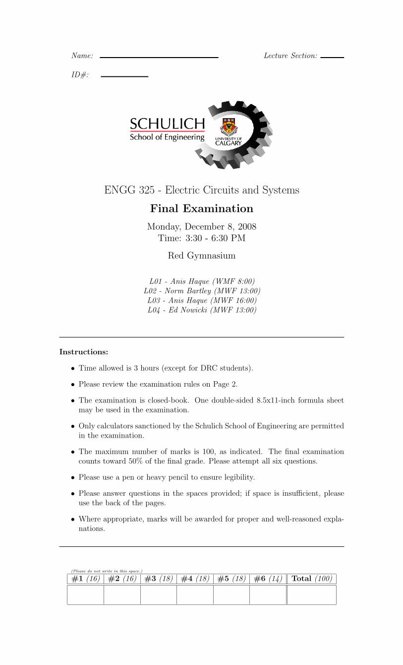
Name: Lecture Section: ID#: ENGG 325 - Electric Circuits and Systems Final Examination Monday, December 8, 2008 Time: 3:30 - 6:30 PM Red Gymnasium L01 - Anis Haque (WMF 8:00) L02 - Norm Bartley (MWF 13:00) L03 - Anis Haque (MWF 16:00) L04 - Ed Nowicki (MWF 13:00) Instructions: • Time allowed is 3 hours (except for DRC students). • Please review the examination rules on Page 2. • The examination is closed-book. One double-sided 8.5x11-inch formula sheet may be used in the examination. • Only calculators sanctioned by the Schulich School of Engineering are permitted in the examination. • The maximum number of marks is 100, as indicated. The final examination counts toward 50% of the final grade. Please attempt all six questions. • Please use a pen or heavy pencil to ensure legibility. • Please answer questions in the spaces provided; if space is insufficient, please use the back of the pages. • Where appropriate, marks will be awarded for proper and well-reasoned expla- nations. (Please do not write in this space.) #1 (16) #2 (16) #3 (18) #4 (18) #5 (18) #6 (14) Total (100)

Welcome message from author
This document is posted to help you gain knowledge. Please leave a comment to let me know what you think about it! Share it to your friends and learn new things together.
Transcript
Name: Lecture Section:
ID#:
ENGG 325 - Electric Circuits and Systems
Final Examination
Monday, December 8, 2008Time: 3:30 - 6:30 PM
Red Gymnasium
L01 - Anis Haque (WMF 8:00)L02 - Norm Bartley (MWF 13:00)L03 - Anis Haque (MWF 16:00)L04 - Ed Nowicki (MWF 13:00)
Instructions:
• Time allowed is 3 hours (except for DRC students).
• Please review the examination rules on Page 2.
• The examination is closed-book. One double-sided 8.5x11-inch formula sheetmay be used in the examination.
• Only calculators sanctioned by the Schulich School of Engineering are permittedin the examination.
• The maximum number of marks is 100, as indicated. The final examinationcounts toward 50% of the final grade. Please attempt all six questions.
• Please use a pen or heavy pencil to ensure legibility.
• Please answer questions in the spaces provided; if space is insufficient, pleaseuse the back of the pages.
• Where appropriate, marks will be awarded for proper and well-reasoned expla-nations.
(Please do not write in this space.)
#1 (16) #2 (16) #3 (18) #4 (18) #5 (18) #6 (14) Total (100)
ENGG 325 Final Examination - Fall 2008 Page 2 of 15
Student Identification
Each candidate must sign the Seating List confirming presence at the examination. Allcandidates for final examinations are required to place their University of Calgary I.D.cards on their desks for the duration of the examination. (Students writing mid-term testscan also be asked to provide identity proof.) Students without an I.D. card who can producean acceptable alternative I.D., e.g., one with a printed name and photograph, are allowedto write the examination.
A student without acceptable I.D. will be required to complete an Identification Form. Theform indicates that there is no guarantee that the examination paper will be graded if anydiscrepancies in identification are discovered after verification with the student’s file. Astudent who refuses to produce identification or who refuses to complete andsign the Identification Form is not permitted to write the examination.
Examination Rules
(1) Students late in arriving will not normally be admitted after one-half hour ofthe examination time has passed.
(2) No candidate will be permitted to leave the examination room until one-halfhour has elapsed after the opening of the examination, nor during the last15 minutes of the examination. All candidates remaining during the last 15minutes of the examination period must remain at their desks until their papershave been collected by an invigilator.
(3) All inquiries and requests must be addressed to supervisors only.(4) The following is strictly prohibited:
(a) speaking to other candidates or communicating with them underany circumstances whatsoever;
(b) bringing into the examination room any textbook, notebook or doc-ument not authorized by the examiner;
(c) making use of calculators, cameras, cell-phones, computers, head-sets, pagers, PDA’s, or any device not authorized by the examiner;
(d) leaving examination papers exposed to view;(e) attempting to read other student’s examination papers.
The penalty for violation of these rules is suspension or expulsion or such otherpenalty as may be determined.
(5) Candidates are requested to write on both sides of the page, unless the examinerhas asked that the left hand page be reserved for rough drafts or calculations.
(6) Discarded matter is to be struck out and not removed by mutilation of theexamination answer book.
(7) Candidates are cautioned against writing on their examination paper any mat-ter extraneous to the actual answering of the question set.
(8) The candidate is to write his/her name on each answer book as directed and isto number each book.
(9) During the examination a candidate must report to a supervisor before leavingthe examination room.
(10) Candidates must stop writing when the signal is given. Answer books mustbe handed to the supervisor-in-charge promptly. Failure to comply with thisregulation will be cause for rejection of an answer paper.
(11) If during the course of an examination a student becomes ill or receives wordof a domestic affliction, the student should report at once to the supervisor,hand in the unfinished paper and request that it be cancelled. If physicaland/or emotional ill health is the cause, the student must report at once toa physican/counsellor so that subsequent application for a deferred examina-tion is supported by a completed Physician/Counsellor Statement form. Stu-dents can consult professionals at University Health Services or Counsellingand Student Development Centre during normal working hours or consult theirphysician/counsellor in the community. Once an examination has beenhanded in for marking a student cannot request that the examina-tion be cancelled for whatever reason. Such a request will be denied.Retroactive withdrawals will also not be considered.
ENGG 325 Final Examination - Fall 2008 Page 3 of 15
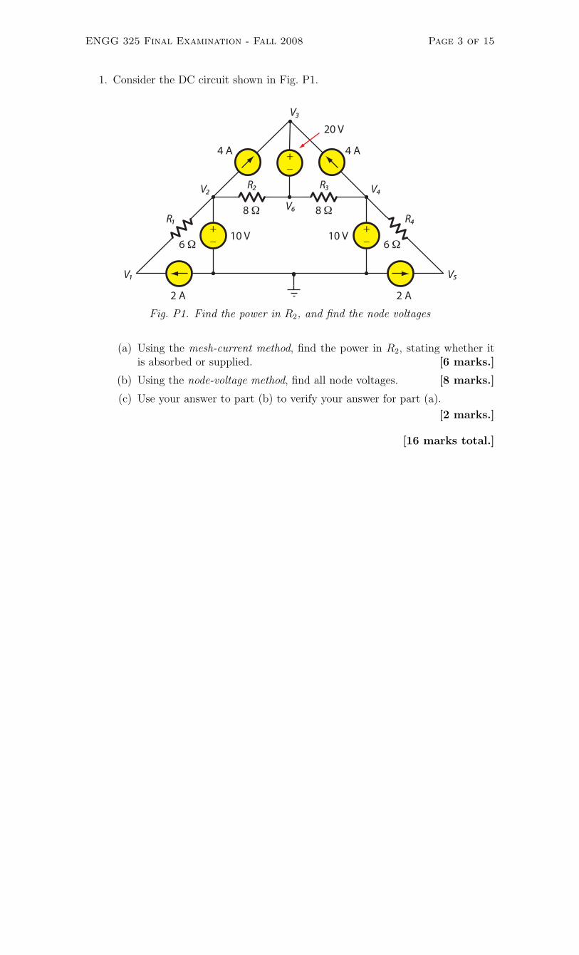
1. Consider the DC circuit shown in Fig. P1.
6 Ω+_
+_
+_
2 A 2 A
10 V 10 V6 Ω
4 A 4 A
20 V
8 Ω 8 ΩR1
R2 R3
R4
V1
V2
V3
V4
V5
V6
Fig. P1. Find the power in R2, and find the node voltages
(a) Using the mesh-current method, find the power in R2, stating whether itis absorbed or supplied. [6 marks.]
(b) Using the node-voltage method, find all node voltages. [8 marks.]
(c) Use your answer to part (b) to verify your answer for part (a).
[2 marks.]
[16 marks total.]

ENGG 325 Final Examination - Fall 2008 Page 4 of 15
(Problem #1 extra workspace.)
ENGG 325 Final Examination - Fall 2008 Page 5 of 15
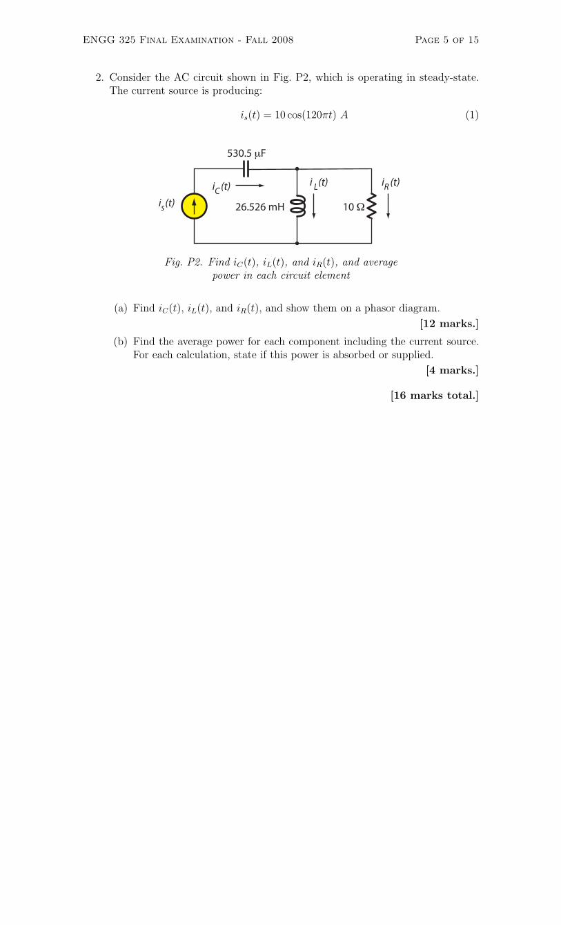
2. Consider the AC circuit shown in Fig. P2, which is operating in steady-state.The current source is producing:
is(t) = 10 cos(120πt) A (1)
10 Ω
530.5 μF
26.526 mHi (t)s
i (t)Ci (t)L i (t)R
Fig. P2. Find iC(t), iL(t), and iR(t), and averagepower in each circuit element
(a) Find iC(t), iL(t), and iR(t), and show them on a phasor diagram.
[12 marks.]
(b) Find the average power for each component including the current source.For each calculation, state if this power is absorbed or supplied.
[4 marks.]
[16 marks total.]

ENGG 325 Final Examination - Fall 2008 Page 6 of 15
(Problem #2 extra workspace.)
ENGG 325 Final Examination - Fall 2008 Page 7 of 15
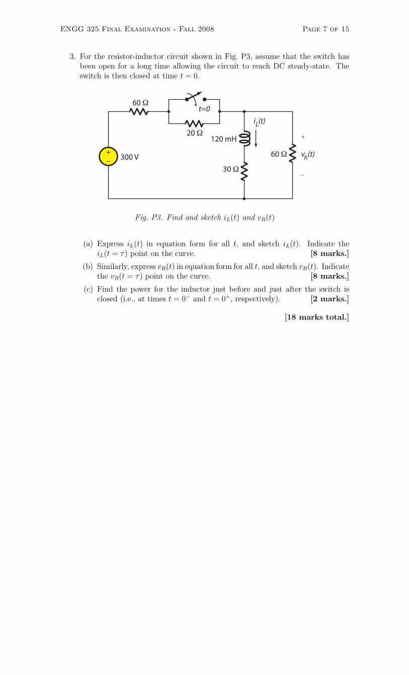
3. For the resistor-inductor circuit shown in Fig. P3, assume that the switch hasbeen open for a long time allowing the circuit to reach DC steady-state. Theswitch is then closed at time t = 0.
+_
30 Ω
+
_
v (t)R
60 Ωt=0
300 V
120 mH
i (t)L
60 Ω
20 Ω
Fig. P3. Find and sketch iL(t) and vR(t)
(a) Express iL(t) in equation form for all t, and sketch iL(t). Indicate theiL(t = τ) point on the curve. [8 marks.]
(b) Similarly, express vR(t) in equation form for all t, and sketch vR(t). Indicatethe vR(t = τ) point on the curve. [8 marks.]
(c) Find the power for the inductor just before and just after the switch isclosed (i.e., at times t = 0− and t = 0+, respectively). [2 marks.]
[18 marks total.]

ENGG 325 Final Examination - Fall 2008 Page 8 of 15
(Problem #3 extra workspace.)

ENGG 325 Final Examination - Fall 2008 Page 9 of 15
4. The op amps in Fig. P4 are ideal.
+_
_
+
13.33K Ω
v
1K Ω
2K Ω
20K Ω
_
+
vs
is1K Ω 5K Ω
2K Ω
2K Ω
10K Ωo2
vo1OP1
OP2io2
Fig. P4. Find vo2(t), output power of op amp OP2
(a) Let is = 2 mA and vs = 1 V. Use the principle of superposition to find v02.
[10 marks.]
(b) Again with is = 2 mA and vs = 1 V, find the power at the output termi-nal of the second op amp OP2, and whether the op amp is supplying orabsorbing power. [4 marks.]
(c) Now let is = 2 cos(1000t) mA and vs = 1 cos(1000t) V. Find the averagepower at the output terminal of the second op amp OP2. [4 marks.]
[18 marks total.]

ENGG 325 Final Examination - Fall 2008 Page 10 of 15
(Problem #4 extra workspace.)
ENGG 325 Final Examination - Fall 2008 Page 11 of 15
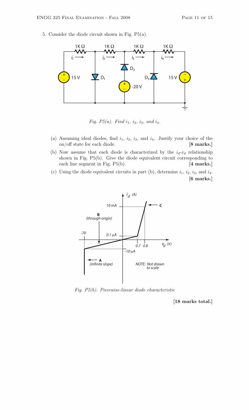
5. Consider the diode circuit shown in Fig. P5(a).
15 V +_
1K Ω
i1
+_
+_
1K Ω 1K Ω 1K Ω
15 V
-20 V
i2 i3 i4
D1
D2
D3
Fig. P5(a). Find i1, i2, i3, and i4.
(a) Assuming ideal diodes, find i1, i2, i3, and i4. Justify your choice of theon/off state for each diode. [8 marks.]
(b) Now assume that each diode is characterized by the id-vd relationshipshown in Fig. P5(b). Give the diode equivalent circuit corresponding toeach line segment in Fig. P5(b). [4 marks.]
(c) Using the diode equivalent circuits in part (b), determine i1, i2, i3, and i4.
[6 marks.]
id
vd
(A)
(V)
0.1 μA
10 mA
0.7 0.8-10 μA
-70
A
(through origin)B
C
NOTE: Not drawnto scale
(in�nite slope)
Fig. P5(b). Piecewise-linear diode characteristic
[18 marks total.]

ENGG 325 Final Examination - Fall 2008 Page 12 of 15
(Problem #5 extra workspace.)

ENGG 325 Final Examination - Fall 2008 Page 13 of 15
(Problem #5 extra workspace.)
ENGG 325 Final Examination - Fall 2008 Page 14 of 15
6. A shunt-connected DC motor (i.e., the DC machine configuration in which thefield windings and the armature are connected in parallel) has been determinedto have the following full-load operating conditions:
• Rated Speed nrated = 3000 rpm;
• Rated Torque Tout = 10 Nm;
• Terminal Voltage VT = 70 V;
• Line (input) Current IL = 52 A;
• Field Loss Pfield = 140.0 W;
• Frictional Loss Prot = 158.4 W.
(a) Under full-load conditions, determine the following:
i. Field Current, IF ;
ii. Armature Current, IA;
iii. Output Power, Pout;
iv. Developed Power, Pdev;
v. Armature EMF Voltage, EA;
vi. Armature Loss, Parm;
vii. Armature Resistance, RA;
viii. Frictional Torque, Trot;
ix. Developed Torque, Tdev;
x. Efficiency, η.
[10 marks.]
(b) Assuming frictional power loss to be constant, determine the speed regu-lation, SR, of this motor. Recall that speed regulation is given by:
SR =nno−load − nfull−load
nfull−load
× 100% (2)
[4 marks.]
[14 marks total.]

ENGG 325 Final Examination - Fall 2008 Page 15 of 15
(Problem #6 extra workspace.)
Related Documents