88 © PROLYTE PRODUCTS GROUP TECHNICAL SPECIFICATIONS ST ROOF techn cal deta ls ST

Welcome message from author
This document is posted to help you gain knowledge. Please leave a comment to let me know what you think about it! Share it to your friends and learn new things together.
Transcript
88 © PROLYTE PRODUCTS GROUPTECHNICAL SPECIFICATIONS
ST R
OO
Fte
chn
cal
det
als
ST
89 © PROLYTE PRODUCTS GROUPTECHNICAL SPECIFICATIONS
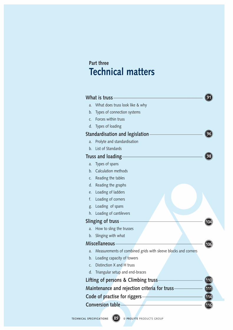
Part three
Technical matters
What is truss -----------------------------------------------------------------------------------------------------------------------------------------------------------------------------------------------------------------------------------
a. What does truss look like & why
b. Types of connection systems
c. Forces within truss
d. Types of loading
Standardisation and legislation ---------------------------------------------------------------------------------------------------------------------------------------
a. Prolyte and standardisation
b. List of Standards
Truss and loading-------------------------------------------------------------------------------------------------------------------------------------------------------------------------------------------------------------
a. Types of spans
b. Calculation methods
c. Reading the tables
d. Reading the graphs
e. Loading of ladders
f. Loading of corners
g. Loading of spans
h. Loading of cantilevers
Slinging of truss -------------------------------------------------------------------------------------------------------------------------------------------------------------------------------------------------------------------
a. How to sling the trusses
b. Slinging with what
Miscellaneous------------------------------------------------------------------------------------------------------------------------------------------------------------------------------------------------------------------------------
a. Measurements of combined grids with sleeve blocks and corners
b. Loading capacity of towers
c. Distinction X and H truss
d. Triangular setup and end-braces
Lifting of persons & Climbing truss-----------------------------------------------------------------------------------------------------------------
Maintenance and rejection criteria for truss------------------------------------------------------------------------
Code of practise for riggers----------------------------------------------------------------------------------------------------------------------------------------------------------
Conversion table --------------------------------------------------------------------------------------------------------------------------------------------------------------------------------------------------------------
91
96
98
104
106
110
111
114
116
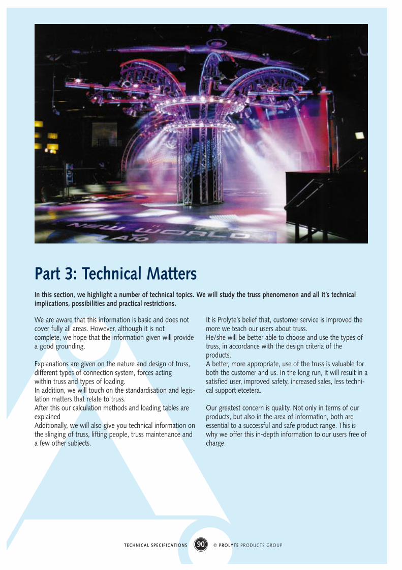
Part 3: Technical Matters
We are aware that this information is basic and does notcover fully all areas. However, although it is notcomplete, we hope that the information given will providea good grounding.
Explanations are given on the nature and design of truss,different types of connection system, forces actingwithin truss and types of loading.In addition, we will touch on the standardisation and legis-lation matters that relate to truss.After this our calculation methods and loading tables areexplainedAdditionally, we will also give you technical information onthe slinging of truss, lifting people, truss maintenance anda few other subjects.
It is Prolyte’s belief that, customer service is improved themore we teach our users about truss. He/she will be better able to choose and use the types oftruss, in accordance with the design criteria of theproducts.A better, more appropriate, use of the truss is valuable forboth the customer and us. In the long run, it will result in asatisfied user, improved safety, increased sales, less techni-cal support etcetera.
Our greatest concern is quality. Not only in terms of ourproducts, but also in the area of information, both areessential to a successful and safe product range. This iswhy we offer this in-depth information to our users free ofcharge.
90 © PROLYTE PRODUCTS GROUPTECHNICAL SPECIFICATIONS
In this section, we highlight a number of technical topics. We will study the truss phenomenon and all it’s technicalimplications, possibilities and practical restrictions.
a. What does truss look like and why
A short historyThe first thing that might strike you when asking what canactually be defined as truss is the word ‘truss’ itself. When the word ‘truss’ was introduced into the entertain-ment business (about 40 years ago), hardly anybodywould have defined truss like this:
A modular structural unit, made of welded aluminiumround tubes. Used for assembling temporary overheadstructures in the entertainment business, to suspend orsupport lighting instruments, sound cabinets and thelike.
At that time, just about everything was used for the pur-pose, varying from round steel bars to antenna-masts.Truss was solely a word for wooden structural frames, usedto build roof parts for houses, barns, medieval cathedralsetc.
Truss, as we now know it, started to develop at the end ofthe 1970’s.The entertainment industry was looking for a solution tothe building of temporary structural spans.Familiar with the spatial lattice structures (found in buil-dings like bridges, factories etc.), engineers used this as thebasis for truss design.
Apart from loading capacity, other more practical factorswere just as important in the development of the truss sys-tems we know today.
Truss now can be defined as:A structural spatial lattice beam• made from welded tubes• composed of modular coupled parts• manufactured in several standardised lengths• used to support equipment in the entertainment industry• supported or suspended at almost any desired point
Truss is made from aluminium, because:• Aluminium has a low self weight, about 1/3 of the
weight of steel• Aluminium is corrosion resistant: less maintenance: no
corrosion protection• Aluminium has a relatively high tensile strength • Aluminium has an attractive finish: bright polished in its
standard form • Aluminium is fully recyclable
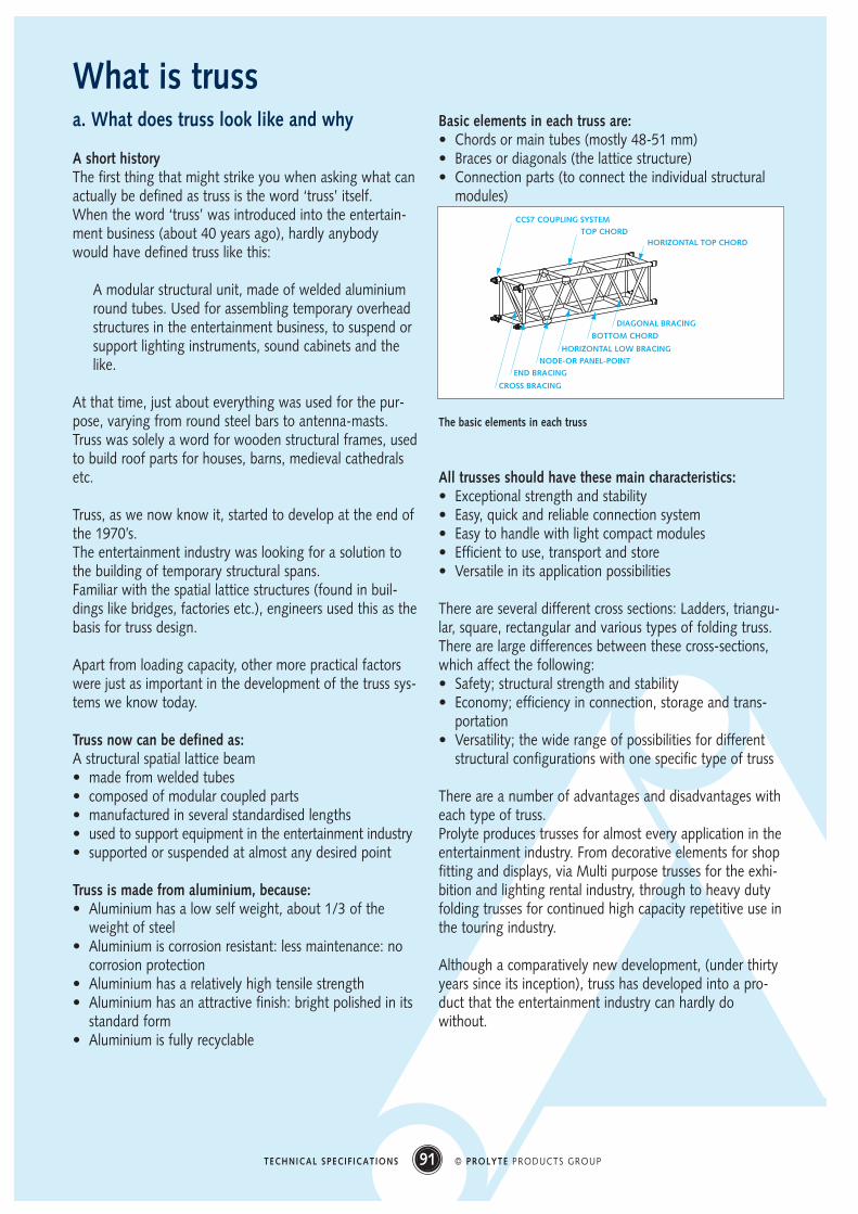
Basic elements in each truss are: • Chords or main tubes (mostly 48-51 mm)• Braces or diagonals (the lattice structure)• Connection parts (to connect the individual structural
modules)
The basic elements in each truss
All trusses should have these main characteristics:• Exceptional strength and stability• Easy, quick and reliable connection system• Easy to handle with light compact modules• Efficient to use, transport and store• Versatile in its application possibilities
There are several different cross sections: Ladders, triangu-lar, square, rectangular and various types of folding truss.There are large differences between these cross-sections,which affect the following:• Safety; structural strength and stability• Economy; efficiency in connection, storage and trans-
portation • Versatility; the wide range of possibilities for different
structural configurations with one specific type of truss
There are a number of advantages and disadvantages witheach type of truss.Prolyte produces trusses for almost every application in theentertainment industry. From decorative elements for shopfitting and displays, via Multi purpose trusses for the exhi-bition and lighting rental industry, through to heavy dutyfolding trusses for continued high capacity repetitive use inthe touring industry.
Although a comparatively new development, (under thirtyyears since its inception), truss has developed into a pro-duct that the entertainment industry can hardly dowithout.
91 © PROLYTE PRODUCTS GROUPTECHNICAL SPECIFICATIONS
What is truss
CCS7 COUPLING SYSTEM
CROSS BRACING
TOP CHORD HORIZONTAL TOP CHORD
END BRACING
NODE-OR PANEL-POINT
HORIZONTAL LOW BRACING
BOTTOM CHORD
DIAGONAL BRACING
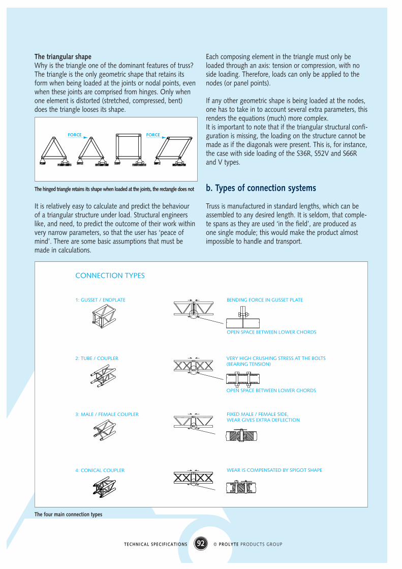
The triangular shape Why is the triangle one of the dominant features of truss?The triangle is the only geometric shape that retains itsform when being loaded at the joints or nodal points, evenwhen these joints are comprised from hinges. Only whenone element is distorted (stretched, compressed, bent)does the triangle looses its shape.
The hinged triangle retains its shape when loaded at the joints, the rectangle does not
It is relatively easy to calculate and predict the behaviourof a triangular structure under load. Structural engineerslike, and need, to predict the outcome of their work withinvery narrow parameters, so that the user has ‘peace ofmind’. There are some basic assumptions that must bemade in calculations.
Each composing element in the triangle must only beloaded through an axis: tension or compression, with noside loading. Therefore, loads can only be applied to thenodes (or panel points).
If any other geometric shape is being loaded at the nodes,one has to take in to account several extra parameters, thisrenders the equations (much) more complex.It is important to note that if the triangular structural confi-guration is missing, the loading on the structure cannot bemade as if the diagonals were present. This is, for instance,the case with side loading of the S36R, S52V and S66Rand V types.
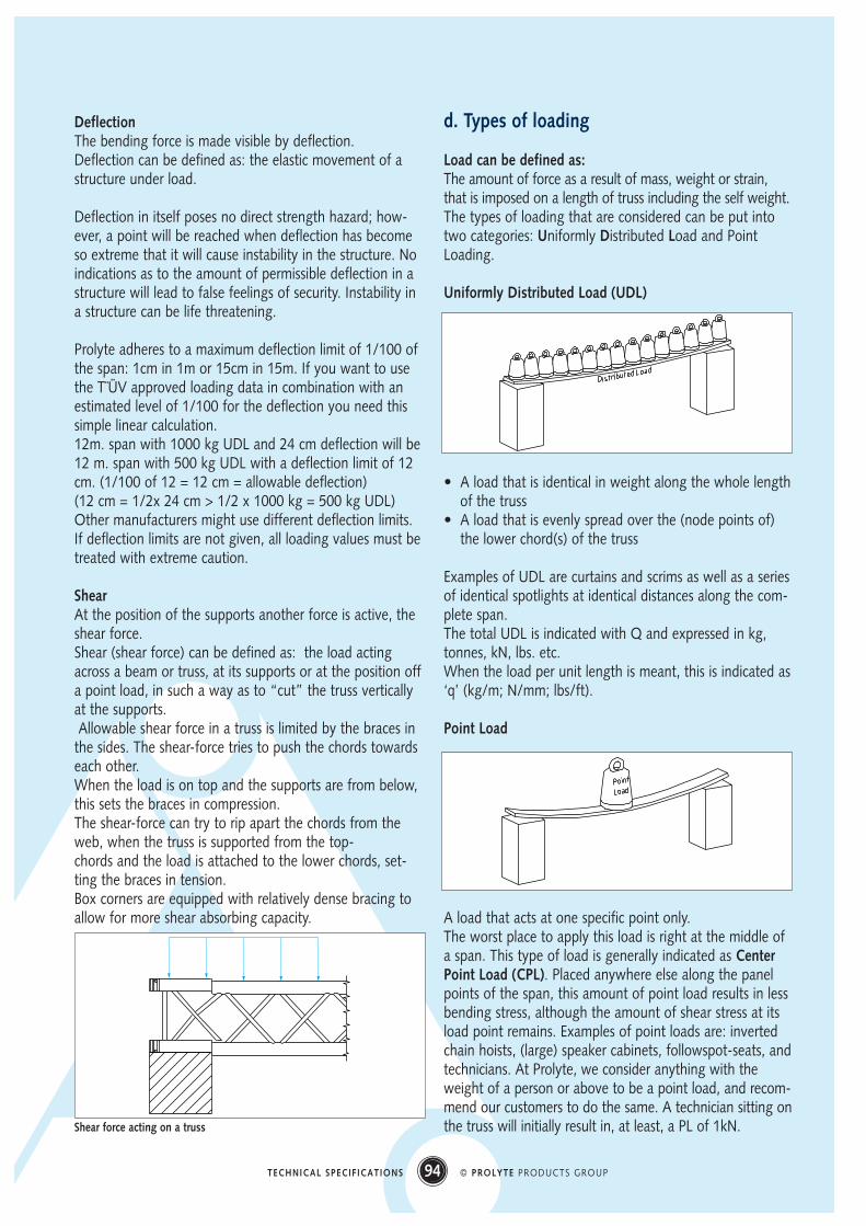
b. Types of connection systems
Truss is manufactured in standard lengths, which can beassembled to any desired length. It is seldom, that comple-te spans as they are used ‘in the field’, are produced asone single module; this would make the product almostimpossible to handle and transport.
92 © PROLYTE PRODUCTS GROUPTECHNICAL SPECIFICATIONS
1: GUSSET / ENDPLATE
2: TUBE / COUPLER
3: MALE / FEMALE COUPLER
4: CONICAL COUPLER
BENDING FORCE IN GUSSET PLATE
OPEN SPACE BETWEEN LOWER CHORDS
VERY HIGH CRUSHING STRESS AT THE BOLTS(BEARING TENSION)
OPEN SPACE BETWEEN LOWER CHORDS
FIXED MALE / FEMALE SIDE,WEAR GIVES EXTRA DEFLECTION
WEAR IS COMPENSATED BY SPIGOT SHAPE
CONNECTION TYPES
FORCE FORCE
The four main connection types

The majority of modules have standardised lengths around2,5 - 3m (8 to 10 ft); however, longer spans are often nee-ded. Therefore, a fast, efficient and easy way of assemblyor connection of the separate truss modules is necessary. Although there are numerous types of truss connections,only a few have proved to be practical in actual use.
Connection systems that do have a seriousmarket share fall in to four basic types:
End- (or gusset-) plate connectionUsing bolts (sometimes the infamous ‘cam-locks’) loadedin tension, and loading the endplates with high bendingforces, way out of line from the chord centers.- Bad line-up; many components; slow assembly; special
tools needed; low loading capacity; danger from use ofincorrect bolts; special hinge sections needed
+ Genderless system; working length = unit length; con-nections difficult to damage; simple to use corners.
Internal tube connectionUsing bolts loaded in shear and loading the chord-wallswith high compressive and shear forces - Difficult to line-up; many components; slow assembly;
special tools needed; connections easy to damage (lea-ding to the discard of entire truss module).
+ Genderless system; working length = unit length.
Fork-plate (or spigots) and cup-cone connectionUsing truss pins (spigots) loaded in double shear, with loa-ding in line with the chord centres. - Gendered truss; elaborate orientation; many corners
required; working length NOT = unit length, connec-tion-parts easy to damage (leading to discard of truss-module); imprecise line-up of modules.
+ Few parts; very quick & easy assembly.
Conical coupler connectionThe best features of all the other connection systems com-bined. Using truss pins (spigots) loaded in double shear,with in-line loading of the chords. - Special hinge parts needed+ Genderless system; precise line-up of modules; very
quick & easy assembly; rigid fixed-moment connection;working length = unit length; connection-parts difficultto damage and easy to replace.
c. Forces within truss
BendingGravity is at work at almost every spot in the universe;accordingly, loading takes place on all structures. The self-weight of a truss will give it the tendency to sagor ‘deflect’ in the unsupported area of the span; this is a
result of loading forces.We call this effect ‘bending’, and the same word is used inmany branches of engineering. ‘Bending’ means: to cons-
train, or strain to tension, causing a straight-line structureto turn into a curve-shape.
The force that is active inside a truss structure is the ben-ding force, leading to compression in the upper chords andtension in the lower chords of the span, and to either ten-sion or compression inside the bracing elements.
The bending force can be quantified as the bendingmoment: the effect resulting from the principle of a forcemultiplied by a distance (F x a) that leads to the bendingof a beam, girder, truss etc, around the neutral axis, at anysection along the span.The bending moment is expressed as M, and can be eitherindicated positive (sagging) or negative (hogging).The bending moment has specific formulas for typical loa-ding situations such as UDL (Uniformly Distributed Load),CPL (Central point Load) on simple supports, cantileversand continuous beams.Units are expressed in the metric system as Nm or kNm (orin the imperial equivalent as ‘lbsft’).If the specific characteristics of the truss are given i.e., sec-tion surface area and height of the truss, (known as themoment of Inertia), the amount of stress in the chords canbe calculated: the bending stress. Every alloy is only capa-ble of taking a limited amount of stress in tension or com-pression before failure occurs.
93 © PROLYTE PRODUCTS GROUPTECHNICAL SPECIFICATIONS
MASS
DETAIL
COMPRESSION
TENSION
MOMENTMOMENT
A span under loading and the resulting forces
DeflectionThe bending force is made visible by deflection.Deflection can be defined as: the elastic movement of astructure under load.
Deflection in itself poses no direct strength hazard; how-ever, a point will be reached when deflection has becomeso extreme that it will cause instability in the structure. Noindications as to the amount of permissible deflection in astructure will lead to false feelings of security. Instability ina structure can be life threatening.
Prolyte adheres to a maximum deflection limit of 1/100 ofthe span: 1cm in 1m or 15cm in 15m. If you want to usethe T¨ÜV approved loading data in combination with anestimated level of 1/100 for the deflection you need thissimple linear calculation.12m. span with 1000 kg UDL and 24 cm deflection will be12 m. span with 500 kg UDL with a deflection limit of 12cm. (1/100 of 12 = 12 cm = allowable deflection)(12 cm = 1/2x 24 cm > 1/2 x 1000 kg = 500 kg UDL)Other manufacturers might use different deflection limits.If deflection limits are not given, all loading values must betreated with extreme caution.
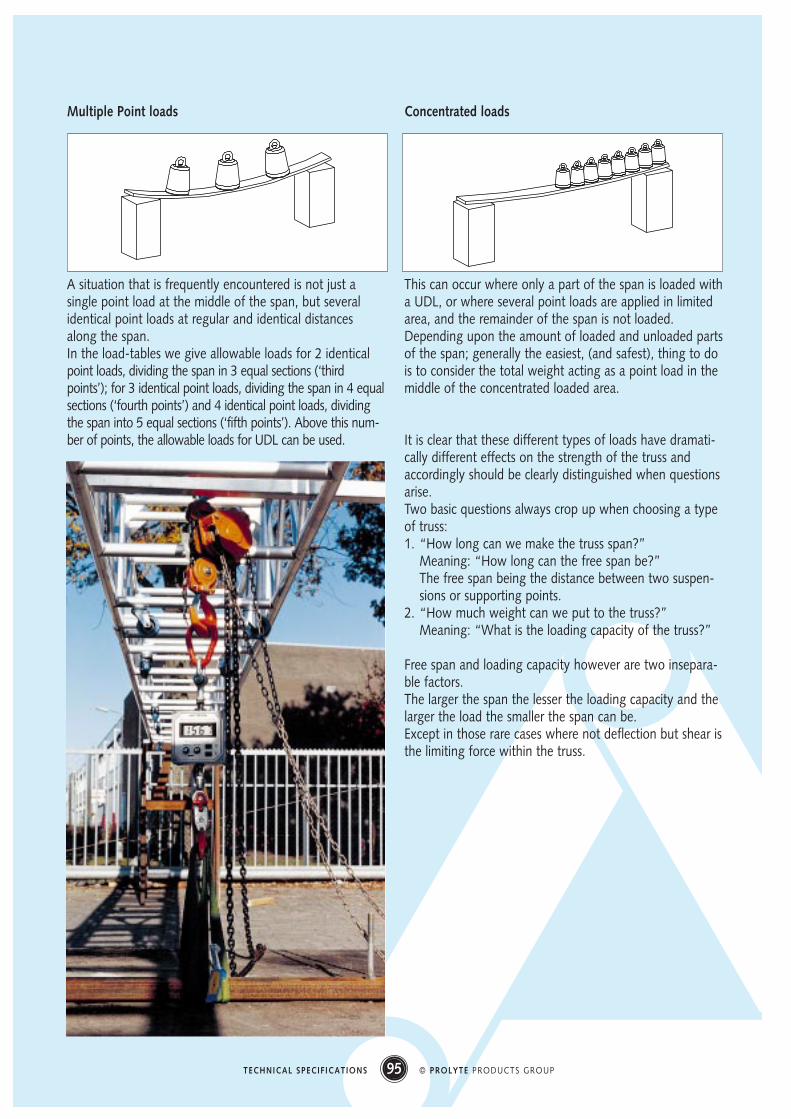
ShearAt the position of the supports another force is active, theshear force.Shear (shear force) can be defined as: the load actingacross a beam or truss, at its supports or at the position offa point load, in such a way as to “cut” the truss verticallyat the supports.Allowable shear force in a truss is limited by the braces in
the sides. The shear-force tries to push the chords towardseach other. When the load is on top and the supports are from below,this sets the braces in compression. The shear-force can try to rip apart the chords from theweb, when the truss is supported from the top-chords and the load is attached to the lower chords, set-ting the braces in tension.Box corners are equipped with relatively dense bracing toallow for more shear absorbing capacity.
d. Types of loading
Load can be defined as:The amount of force as a result of mass, weight or strain,that is imposed on a length of truss including the self weight.The types of loading that are considered can be put intotwo categories: Uniformly Distributed Load and PointLoading.
Uniformly Distributed Load (UDL)
• A load that is identical in weight along the whole lengthof the truss
• A load that is evenly spread over the (node points of)the lower chord(s) of the truss
Examples of UDL are curtains and scrims as well as a seriesof identical spotlights at identical distances along the com-plete span.The total UDL is indicated with Q and expressed in kg,tonnes, kN, lbs. etc.When the load per unit length is meant, this is indicated as‘q’ (kg/m; N/mm; lbs/ft).
Point Load
A load that acts at one specific point only.The worst place to apply this load is right at the middle ofa span. This type of load is generally indicated as CenterPoint Load (CPL). Placed anywhere else along the panelpoints of the span, this amount of point load results in lessbending stress, although the amount of shear stress at itsload point remains. Examples of point loads are: invertedchain hoists, (large) speaker cabinets, followspot-seats, andtechnicians. At Prolyte, we consider anything with theweight of a person or above to be a point load, and recom-mend our customers to do the same. A technician sitting onthe truss will initially result in, at least, a PL of 1kN.
94 © PROLYTE PRODUCTS GROUPTECHNICAL SPECIFICATIONS
Shear force acting on a truss
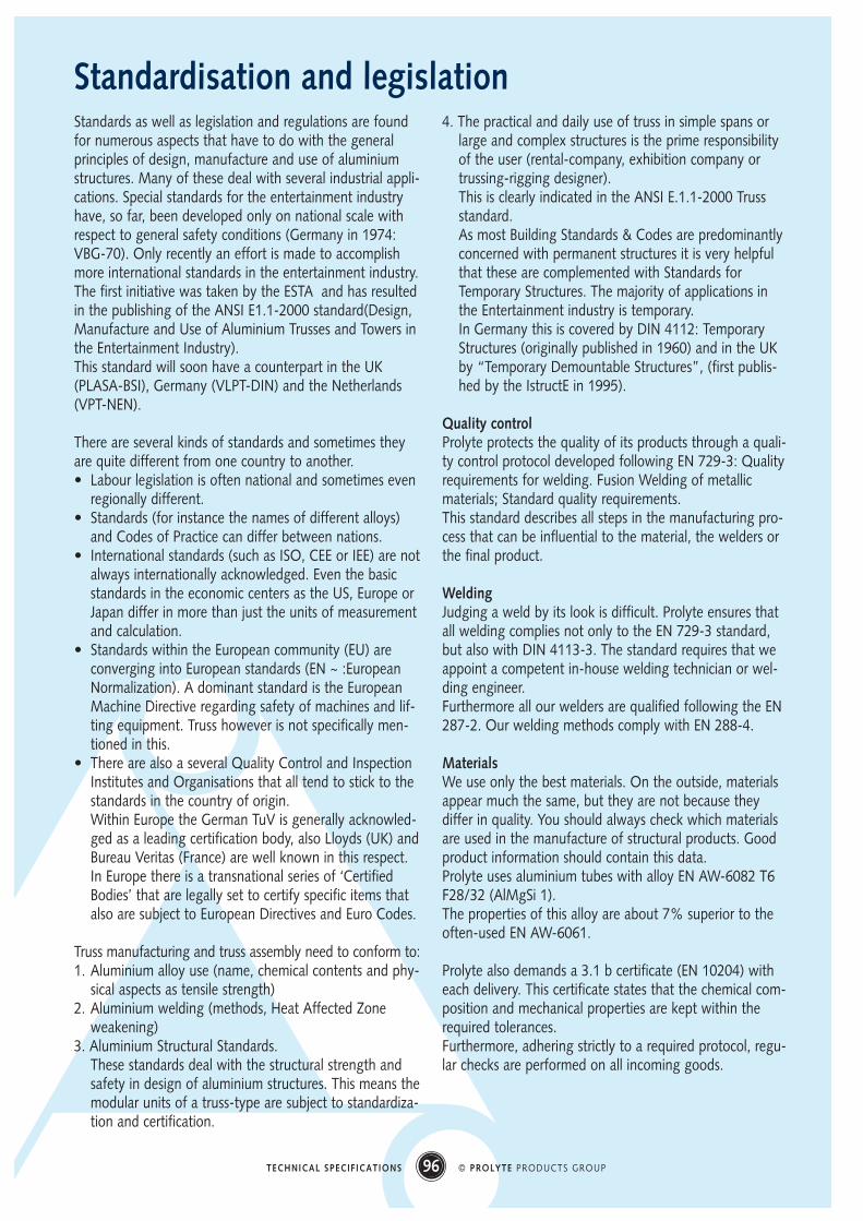
Multiple Point loads
A situation that is frequently encountered is not just asingle point load at the middle of the span, but severalidentical point loads at regular and identical distancesalong the span.In the load-tables we give allowable loads for 2 identicalpoint loads, dividing the span in 3 equal sections (‘thirdpoints’); for 3 identical point loads, dividing the span in 4 equalsections (‘fourth points’) and 4 identical point loads, dividingthe span into 5 equal sections (‘fifth points’). Above this num-ber of points, the allowable loads for UDL can be used.
Concentrated loads
This can occur where only a part of the span is loaded witha UDL, or where several point loads are applied in limitedarea, and the remainder of the span is not loaded. Depending upon the amount of loaded and unloaded partsof the span; generally the easiest, (and safest), thing to dois to consider the total weight acting as a point load in themiddle of the concentrated loaded area.
It is clear that these different types of loads have dramati-cally different effects on the strength of the truss andaccordingly should be clearly distinguished when questionsarise.Two basic questions always crop up when choosing a typeof truss:1. “How long can we make the truss span?”
Meaning: “How long can the free span be?”The free span being the distance between two suspen-sions or supporting points.
2. “How much weight can we put to the truss?”Meaning: “What is the loading capacity of the truss?”
Free span and loading capacity however are two insepara-ble factors.The larger the span the lesser the loading capacity and thelarger the load the smaller the span can be.Except in those rare cases where not deflection but shear isthe limiting force within the truss.
95 © PROLYTE PRODUCTS GROUPTECHNICAL SPECIFICATIONS
96 © PROLYTE PRODUCTS GROUPTECHNICAL SPECIFICATIONS
Standardisation and legislationStandards as well as legislation and regulations are foundfor numerous aspects that have to do with the generalprinciples of design, manufacture and use of aluminiumstructures. Many of these deal with several industrial appli-cations. Special standards for the entertainment industryhave, so far, been developed only on national scale withrespect to general safety conditions (Germany in 1974:VBG-70). Only recently an effort is made to accomplishmore international standards in the entertainment industry. The first initiative was taken by the ESTA and has resultedin the publishing of the ANSI E1.1-2000 standard(Design,Manufacture and Use of Aluminium Trusses and Towers inthe Entertainment Industry). This standard will soon have a counterpart in the UK(PLASA-BSI), Germany (VLPT-DIN) and the Netherlands(VPT-NEN).
There are several kinds of standards and sometimes theyare quite different from one country to another.• Labour legislation is often national and sometimes even
regionally different.• Standards (for instance the names of different alloys)
and Codes of Practice can differ between nations.• International standards (such as ISO, CEE or IEE) are not
always internationally acknowledged. Even the basicstandards in the economic centers as the US, Europe orJapan differ in more than just the units of measurementand calculation.
• Standards within the European community (EU) areconverging into European standards (EN ~ :EuropeanNormalization). A dominant standard is the EuropeanMachine Directive regarding safety of machines and lif-ting equipment. Truss however is not specifically men-tioned in this.
• There are also a several Quality Control and InspectionInstitutes and Organisations that all tend to stick to thestandards in the country of origin. Within Europe the German TuV is generally acknowled-ged as a leading certification body, also Lloyds (UK) andBureau Veritas (France) are well known in this respect. In Europe there is a transnational series of ‘CertifiedBodies’ that are legally set to certify specific items thatalso are subject to European Directives and Euro Codes.
Truss manufacturing and truss assembly need to conform to:1. Aluminium alloy use (name, chemical contents and phy-
sical aspects as tensile strength)2. Aluminium welding (methods, Heat Affected Zone
weakening)3. Aluminium Structural Standards.
These standards deal with the structural strength andsafety in design of aluminium structures. This means themodular units of a truss-type are subject to standardiza-tion and certification.
4. The practical and daily use of truss in simple spans orlarge and complex structures is the prime responsibilityof the user (rental-company, exhibition company ortrussing-rigging designer). This is clearly indicated in the ANSI E.1.1-2000 Trussstandard. As most Building Standards & Codes are predominantlyconcerned with permanent structures it is very helpfulthat these are complemented with Standards forTemporary Structures. The majority of applications inthe Entertainment industry is temporary. In Germany this is covered by DIN 4112: TemporaryStructures (originally published in 1960) and in the UKby “Temporary Demountable Structures”, (first publis-hed by the IstructE in 1995).
Quality controlProlyte protects the quality of its products through a quali-ty control protocol developed following EN 729-3: Qualityrequirements for welding. Fusion Welding of metallicmaterials; Standard quality requirements.This standard describes all steps in the manufacturing pro-cess that can be influential to the material, the welders orthe final product.
WeldingJudging a weld by its look is difficult. Prolyte ensures thatall welding complies not only to the EN 729-3 standard,but also with DIN 4113-3. The standard requires that weappoint a competent in-house welding technician or wel-ding engineer.Furthermore all our welders are qualified following the EN287-2. Our welding methods comply with EN 288-4.
MaterialsWe use only the best materials. On the outside, materialsappear much the same, but they are not because theydiffer in quality. You should always check which materialsare used in the manufacture of structural products. Goodproduct information should contain this data.Prolyte uses aluminium tubes with alloy EN AW-6082 T6F28/32 (AlMgSi 1).The properties of this alloy are about 7% superior to theoften-used EN AW-6061.
Prolyte also demands a 3.1 b certificate (EN 10204) witheach delivery. This certificate states that the chemical com-position and mechanical properties are kept within therequired tolerances.Furthermore, adhering strictly to a required protocol, regu-lar checks are performed on all incoming goods.

97 © PROLYTE PRODUCTS GROUPTECHNICAL SPECIFICATIONS
DIN 1748-1 Wrought aluminium and aluminium extrudedsections; Properties
DIN 18000-1 Modular co-ordination in building
DIN 4112 Temporary structures; code of practice for design andconstruction
DIN 4113-1 Aluminium constructions under predominantlystatic loading; static analysis and structural design
DIN 4113-2 Aluminium constructions under predominantlystatic loading
DIN 931 Hexagon socket set screws with cone point, ISO4026 modified
EN 10002-1 Tensile testing of metallic materials.Method of test at ambient temperature.
EN 287-2 Approval testing of welders- Fusion Welding.Part 2: Aluminium and aluminium alloys
EN 288-3 Specification and approval of welding procedures formetallic materials- Part 3:Welding procedures testsfor the arc welding of steels.
EN 288-4 Specification and approval of welding procedures formetallic materials- Part 3:Welding procedures testsfor the arc welding of Aluminium andaluminium alloys.
EN 292-1 Safety of machinery. Basic concepts, general princip-les for design.Part 1: Basic terminology, methodology.
EN 292-2 Safety of machinery. Basic concepts, generalprinciples for design.Part 2: Technical principles and specifications.
EN 729-3 Quality requirements for welding. Fusion welding ofmetallic materials.Part 3: Standard quality requirements.
ISO 10042 Arc-welded joints in aluminium and its weldablealloys. Guidance on quality levels for imperfections.
NEN 2063 Arc welding. Fatigue loaded structures. Calculation ofwelded joints in unalloyed and low-alloy steel up toand including Fe 510 (Fe52).
NEN 6710 Regulations for the calculation of building structuresTGB 1990. Design of aluminium structures
ANSI E1-1-2000
Product hallmarksIn close co-operation with the RWTüV (Germany’s notifiedtest and certification body), Prolyte has obtained a ‘Bau-artPrüfung’ for all their truss series.
Our tower systems have the CE hallmark and all our con-structions and roof systems can be supplied with a stabilitycertificate, the so-called ‘Baubuch’.
Prolyte Products are made in compliance to the following standards:
98 © PROLYTE PRODUCTS GROUPTECHNICAL SPECIFICATIONS
Practice & TheoryEven the most accepted theoretical models for strengthand stability calculations will not be able to cover all thevarious situations that clients have to deal with on a day-to-day basis.As a manufacturer, an awareness of this situation is essen-tial, so that we are able to offer solutions that work andprove valuable in the long term.
At our engineering and sales departments, we employpeople that have ‘hands on’ experience in the field of rig-ging and trussing. Their invaluable knowledge and expe-rience combined with the pool of knowledge that Prolytealready has, as a major manufacturer of truss, is a majorasset.Our awareness of the lack of theoretical knowledge oftruss-users makes us mindful of our responsibility to edu-cate the end user. This ensures that the end user gets safelong lasting use of our products.
a. Types of spans
Simply supported span
The tables represented show the values for simply suppor-ted spans, which are the most commonly found types ofspan in the industry.This type of span is supported at both ends of the truss,permitting movement of the truss in between the supports,caused by deflection because of loading.
Fixed span
Data that show values for fixed spans are almost comple-tely hypothetical, because in our industry this type of sup-port is rarely used. Manufacturers that use this type ofdata only want to show high figures (‘hyping’ their pro-ducts), but, essentially, are misleading the customers.
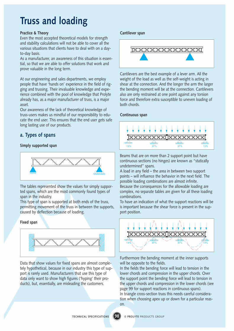
Cantilever span
Cantilevers are the best example of a lever arm. All theweight of the load as well as the self-weight is acting inshear at the connection. And the longer the arm the largerthe bending moment will be at the connection. Cantileversalso are only restrained at one point against any torsionforce and therefore extra susceptible to uneven loading ofboth chords.
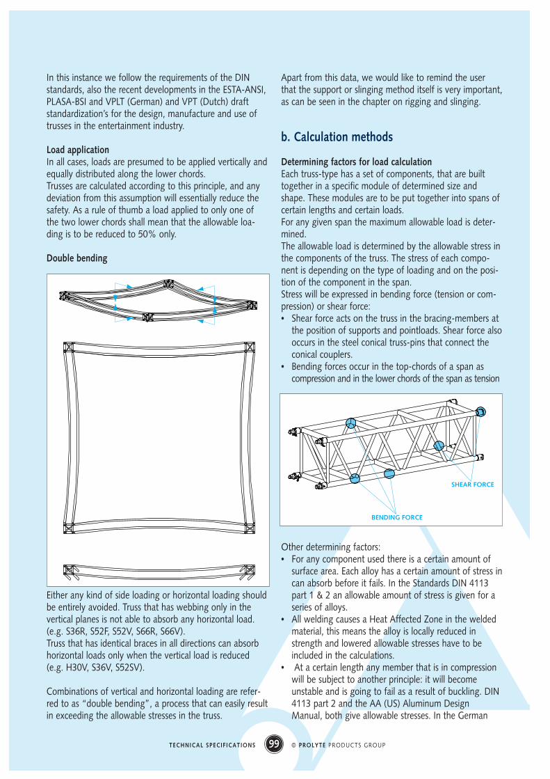
Continuous span
Beams that are on more than 2 support point but havecontinuous sections (no hinges) are known as “staticallyundetermined” spans. A load in any field – the area in between two supportpoints – will influence the behavior in the next field. Thepossible loading combinations are almost infinite.Because the consequences for the allowable loading arecomplex, no separate tables are given for all these loadingcombinations.To have an indication of what the support reactions will beis important because the shear force is present in the sup-port position.
Furthermore the bending moment at the inner supportswill be opposite to the fields. In the fields the bending force will lead to tension in thelower chords and compression in the upper chords. Overthe support point the bending force will lead to tension inthe upper chords and compression in the lower chords (seepage 99 for support reactions in continuous spans).In triangle cross-section truss this needs careful considera-tion when choosing apex up or down for a particular reas-on.
Truss and loading
13% 37% 37% 13%
13% 37% 37% 13%
99 © PROLYTE PRODUCTS GROUPTECHNICAL SPECIFICATIONS
In this instance we follow the requirements of the DINstandards, also the recent developments in the ESTA-ANSI,PLASA-BSI and VPLT (German) and VPT (Dutch) draftstandardization’s for the design, manufacture and use oftrusses in the entertainment industry.
Load applicationIn all cases, loads are presumed to be applied vertically andequally distributed along the lower chords.Trusses are calculated according to this principle, and anydeviation from this assumption will essentially reduce thesafety. As a rule of thumb a load applied to only one ofthe two lower chords shall mean that the allowable loa-ding is to be reduced to 50% only.
Double bending
Either any kind of side loading or horizontal loading shouldbe entirely avoided. Truss that has webbing only in thevertical planes is not able to absorb any horizontal load.(e.g. S36R, S52F, S52V, S66R, S66V).Truss that has identical braces in all directions can absorbhorizontal loads only when the vertical load is reduced(e.g. H30V, S36V, S52SV).
Combinations of vertical and horizontal loading are refer-red to as “double bending”, a process that can easily resultin exceeding the allowable stresses in the truss.
Apart from this data, we would like to remind the userthat the support or slinging method itself is very important,as can be seen in the chapter on rigging and slinging.
b. Calculation methods
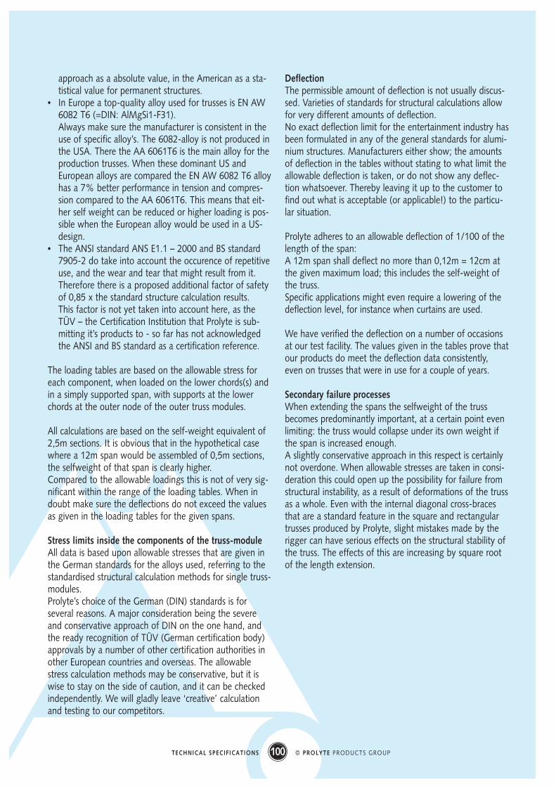
Determining factors for load calculationEach truss-type has a set of components, that are builttogether in a specific module of determined size andshape. These modules are to be put together into spans ofcertain lengths and certain loads. For any given span the maximum allowable load is deter-mined. The allowable load is determined by the allowable stress inthe components of the truss. The stress of each compo-nent is depending on the type of loading and on the posi-tion of the component in the span. Stress will be expressed in bending force (tension or com-pression) or shear force: • Shear force acts on the truss in the bracing-members at
the position of supports and pointloads. Shear force alsooccurs in the steel conical truss-pins that connect theconical couplers.
• Bending forces occur in the top-chords of a span ascompression and in the lower chords of the span as tension
Other determining factors:• For any component used there is a certain amount of
surface area. Each alloy has a certain amount of stress incan absorb before it fails. In the Standards DIN 4113part 1 & 2 an allowable amount of stress is given for aseries of alloys.
• All welding causes a Heat Affected Zone in the weldedmaterial, this means the alloy is locally reduced instrength and lowered allowable stresses have to beincluded in the calculations.
• At a certain length any member that is in compressionwill be subject to another principle: it will becomeunstable and is going to fail as a result of buckling. DIN4113 part 2 and the AA (US) Aluminum DesignManual, both give allowable stresses. In the German
BENDING FORCE
SHEAR FORCE
100 © PROLYTE PRODUCTS GROUPTECHNICAL SPECIFICATIONS
approach as a absolute value, in the American as a sta-tistical value for permanent structures.
• In Europe a top-quality alloy used for trusses is EN AW6082 T6 (=DIN: AlMgSi1-F31). Always make sure the manufacturer is consistent in theuse of specific alloy’s. The 6082-alloy is not produced inthe USA. There the AA 6061T6 is the main alloy for theproduction trusses. When these dominant US andEuropean alloys are compared the EN AW 6082 T6 alloyhas a 7% better performance in tension and compres-sion compared to the AA 6061T6. This means that eit-her self weight can be reduced or higher loading is pos-sible when the European alloy would be used in a US-design.
• The ANSI standard ANS E1.1 – 2000 and BS standard7905-2 do take into account the occurence of repetitiveuse, and the wear and tear that might result from it.Therefore there is a proposed additional factor of safetyof 0,85 x the standard structure calculation results. This factor is not yet taken into account here, as theTÜV – the Certification Institution that Prolyte is sub-mitting it’s products to - so far has not acknowledgedthe ANSI and BS standard as a certification reference.
The loading tables are based on the allowable stress foreach component, when loaded on the lower chords(s) andin a simply supported span, with supports at the lowerchords at the outer node of the outer truss modules.
All calculations are based on the self-weight equivalent of2,5m sections. It is obvious that in the hypothetical casewhere a 12m span would be assembled of 0,5m sections,the selfweight of that span is clearly higher. Compared to the allowable loadings this is not of very sig-nificant within the range of the loading tables. When indoubt make sure the deflections do not exceed the valuesas given in the loading tables for the given spans.
Stress limits inside the components of the truss-moduleAll data is based upon allowable stresses that are given inthe German standards for the alloys used, referring to thestandardised structural calculation methods for single truss-modules.Prolyte’s choice of the German (DIN) standards is forseveral reasons. A major consideration being the severeand conservative approach of DIN on the one hand, andthe ready recognition of TÜV (German certification body)approvals by a number of other certification authorities inother European countries and overseas. The allowablestress calculation methods may be conservative, but it iswise to stay on the side of caution, and it can be checkedindependently. We will gladly leave ‘creative’ calculationand testing to our competitors.
DeflectionThe permissible amount of deflection is not usually discus-sed. Varieties of standards for structural calculations allowfor very different amounts of deflection.No exact deflection limit for the entertainment industry hasbeen formulated in any of the general standards for alumi-nium structures. Manufacturers either show; the amountsof deflection in the tables without stating to what limit theallowable deflection is taken, or do not show any deflec-tion whatsoever. Thereby leaving it up to the customer tofind out what is acceptable (or applicable!) to the particu-lar situation.
Prolyte adheres to an allowable deflection of 1/100 of thelength of the span:A 12m span shall deflect no more than 0,12m = 12cm atthe given maximum load; this includes the self-weight ofthe truss.Specific applications might even require a lowering of thedeflection level, for instance when curtains are used.
We have verified the deflection on a number of occasionsat our test facility. The values given in the tables prove thatour products do meet the deflection data consistently,even on trusses that were in use for a couple of years.
Secondary failure processesWhen extending the spans the selfweight of the trussbecomes predominantly important, at a certain point evenlimiting: the truss would collapse under its own weight ifthe span is increased enough.A slightly conservative approach in this respect is certainlynot overdone. When allowable stresses are taken in consi-deration this could open up the possibility for failure fromstructural instability, as a result of deformations of the trussas a whole. Even with the internal diagonal cross-bracesthat are a standard feature in the square and rectangulartrusses produced by Prolyte, slight mistakes made by therigger can have serious effects on the structural stability ofthe truss. The effects of this are increasing by square rootof the length extension.
101 © PROLYTE PRODUCTS GROUPTECHNICAL SPECIFICATIONS
c. Reading the tables
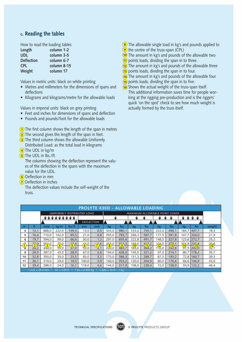
How to read the loading tablesLength column 1-2UDL column 3-5Deflection column 6-7CPL column 8-15Weight column 17
Values in metric units: black on white printing• Metres and millimeters for the dimensions of spans and
deflections• Kilograms and kilograms/metre for the allowable loads
Values in imperial units: black on grey printing• Feet and inches for dimensions of spans and deflection• Pounds and pounds/foot for the allowable loads
The first column shows the length of the span in metresThe second gives the length of the span in feet.The third column shows the allowable UniformlyDistributed Load: as the total load in kilogramsThe UDL in kg/mThe UDL in lbs./ft.The columns showing the deflection represent the valu-es of the deflection in the spans with the maximumvalue for the UDL.Deflection in mmDeflection in inchesThe deflection values include the self-weight of thetruss.
The allowable single load in kg’s and pounds applied tothe centre of the truss-span (CPL)The amount in kg’s and pounds of the allowable twopoints loads, dividing the span in to three.The amount in kg’s and pounds of the allowable threepoints loads, dividing the span in to four.The amount in kg’s and pounds of the allowable fourpoints loads, dividing the span in to five.Shows the actual weight of the truss-span itself.This additional information saves time for people wor-king at the rigging pre-production and is the riggers’quick ‘on the spot’ check to see how much weight isactually formed by the truss itself.
1
2
3
4
5
6
7
8
9
10
11
12
13
14
15
16
040506070809101112
1 inch = 25.4 mm | 1m = 3.28 ft | 1 lbs = 0.453 kg | 1 daN = 10 N ~ 1 kg
m
PROLYTE X30D - ALLOWABLE LOADINGUNIFORMLY DISTRIBUTED LOAD MAXIMUM ALLOWABLE POINT LOADS
ft total kg/m lbs/ft mm inch kg lbs kg lbs kg lbs kg lbs weight
DEFLECTION
13,1 888,0 222,0 149,4 13,0 0,5 444,0 980,1 333,0 735,1 222,0 490,1 184,7 407,7 18,316,4 710,0 142,0 95,5 21,0 0,8 355,0 783,7 266,3 587,7 177,5 391,8 147,7 326,0 21,919,7 594,0 99,0 66,6 30,0 1,2 297,0 655,6 222,8 491,7 148,5 327,8 123,6 272,7 25,223,0 504,0 72,0 48,4 41,0 1,6 252,0 556,3 189,0 417,2 126,0 278,1 104,8 231,4 28,626,2 440,0 55,0 37,0 53,0 2,1 220,0 485,7 165,0 364,2 110,0 242,8 91,5 202,0 32,129,5 387,0 43,0 28,9 67,0 2,6 194,0 428,3 145,5 321,2 97,0 214,1 80,7 178,2 35,732,8 350,0 35,0 23,5 83,0 3,3 175,0 386,3 131,3 289,7 87,5 193,2 72,8 160,7 39,336,1 319,0 29,0 19,5 100,0 3,9 160,0 353,2 120,0 264,9 80,0 176,6 66,6 146,9 43,039,4 288,0 24,0 16,1 118,0 4,6 144,0 317,9 108,0 238,4 72,0 158,9 59,9 132,2 46,4
1 2 3 4 5 6 7 8 9 10 1211 13 14 15 16
4 5 6 7 8 9 1 0 1 1 1 2 UNIFORMLY DISTRIBUTED LOADLOAD PER METER
POINT LOADDEFLECTION
LOAD (KG)
DEF
LEC
TIO
N in
MM
SPAN (M)
0
100
200
300
400
500
600
700
800
900
1000
0
13
26
39
52
65
78
91
104
117
130
PROLYTE H30D - LOADING
PROLYTE LADDER TRUSS - ALLOWABLE LOADING
UDL/mPOINTLOAD UDL/mPOINTLOAD UDL/mPOINTLOAD UDL/mPOINTLOAD UDL/mPOINTLOAD UDL/mPOINTLOAD UDL/mPOINTLOAD
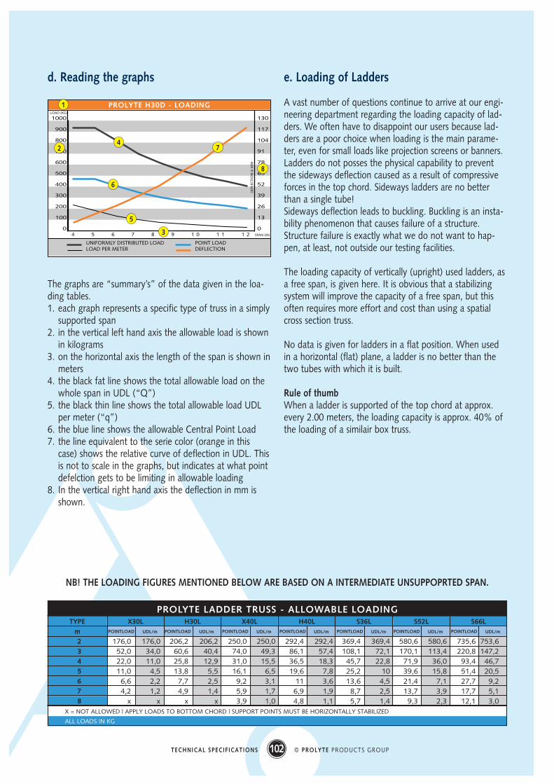
d. Reading the graphs
The graphs are “summary’s” of the data given in the loa-ding tables.1. each graph represents a specific type of truss in a simply
supported span2. in the vertical left hand axis the allowable load is shown
in kilograms3. on the horizontal axis the length of the span is shown in
meters4. the black fat line shows the total allowable load on the
whole span in UDL (“Q”)5. the black thin line shows the total allowable load UDL
per meter (“q”)6. the blue line shows the allowable Central Point Load7. the line equivalent to the serie color (orange in this
case) shows the relative curve of deflection in UDL. Thisis not to scale in the graphs, but indicates at what pointdefelction gets to be limiting in allowable loading
8. In the vertical right hand axis the deflection in mm isshown.
e. Loading of Ladders
A vast number of questions continue to arrive at our engi-neering department regarding the loading capacity of lad-ders. We often have to disappoint our users because lad-ders are a poor choice when loading is the main parame-ter, even for small loads like projection screens or banners.Ladders do not posses the physical capability to preventthe sideways deflection caused as a result of compressiveforces in the top chord. Sideways ladders are no betterthan a single tube!Sideways deflection leads to buckling. Buckling is an insta-bility phenomenon that causes failure of a structure.Structure failure is exactly what we do not want to hap-pen, at least, not outside our testing facilities.
The loading capacity of vertically (upright) used ladders, asa free span, is given here. It is obvious that a stabilizingsystem will improve the capacity of a free span, but thisoften requires more effort and cost than using a spatialcross section truss.
No data is given for ladders in a flat position. When usedin a horizontal (flat) plane, a ladder is no better than thetwo tubes with which it is built.
Rule of thumbWhen a ladder is supported of the top chord at approx.every 2.00 meters, the loading capacity is approx. 40% ofthe loading of a similair box truss.
102 © PROLYTE PRODUCTS GROUPTECHNICAL SPECIFICATIONS
m02030405060708
X = NOT ALLOWED | APPLY LOADS TO BOTTOM CHORD | SUPPORT POINTS MUST BE HORIZONTALLY STABILIZED
ALL LOADS IN KG
TYPE X30L H30L X40L H40L S36L S52L S66L
176,0 176,0 206,2 206,2 250,0 250,0 292,4 292,4 369,4 369,4 580,6 580,6 735,6 753,652,0 34,0 60,6 40,4 74,0 49,3 86,1 57,4 108,1 72,1 170,1 113,4 220,8 147,222,0 11,0 25,8 12,9 31,0 15,5 36,5 18,3 45,7 22,8 71,9 36,0 93,4 46,711,0 4,5 13,8 5,5 16,1 6,5 19,6 7,8 25,2 10 39,6 15,8 51,4 20,5
6,6 2,2 7,7 2,5 9,2 3,1 11 3,6 13,6 4,5 21,4 7,1 27,7 9,24,2 1,2 4,9 1,4 5,9 1,7 6,9 1,9 8,7 2,5 13,7 3,9 17,7 5,1
x x x x 3,9 1,0 4,8 1,1 5,7 1,4 9,3 2,3 12,1 3,0
1
2
3
4
5
6
7
8
NB! THE LOADING FIGURES MENTIONED BELOW ARE BASED ON A INTERMEDIATE UNSUPPOPRTED SPAN.
103 © PROLYTE PRODUCTS GROUPTECHNICAL SPECIFICATIONS
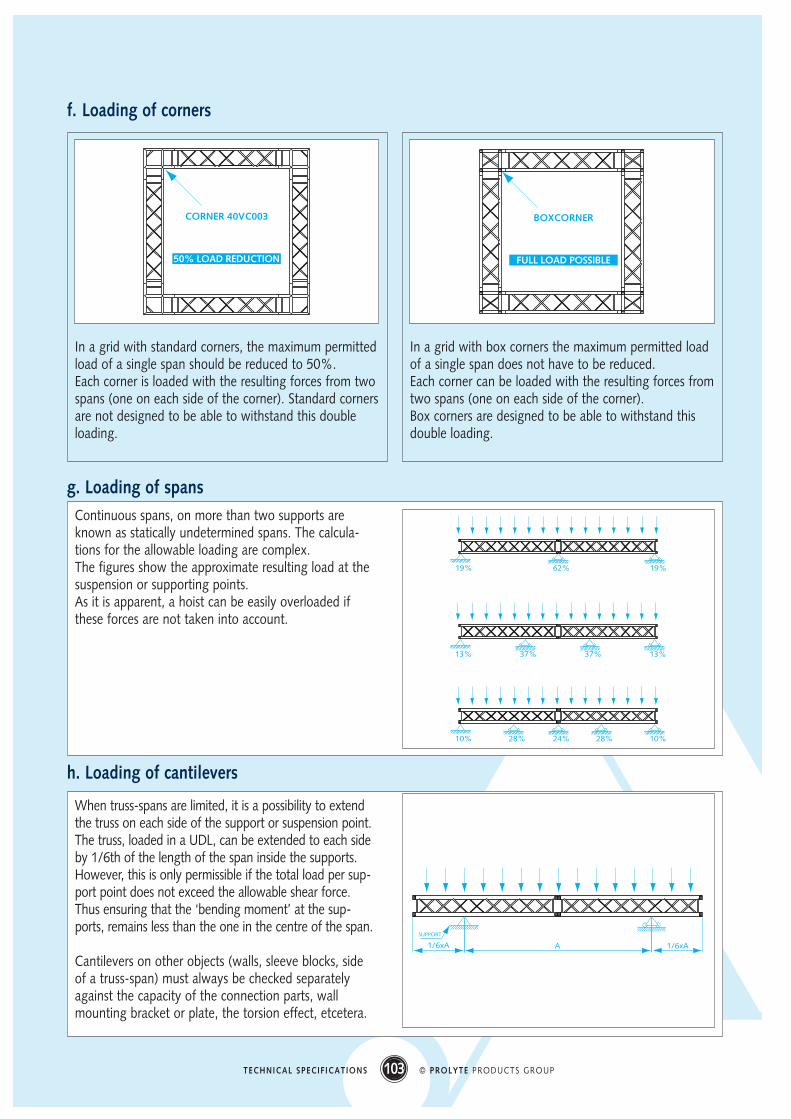
f. Loading of corners
In a grid with standard corners, the maximum permittedload of a single span should be reduced to 50%. Each corner is loaded with the resulting forces from twospans (one on each side of the corner). Standard cornersare not designed to be able to withstand this doubleloading.
CORNER 40VC003
50% LOAD REDUCTION
In a grid with box corners the maximum permitted loadof a single span does not have to be reduced. Each corner can be loaded with the resulting forces fromtwo spans (one on each side of the corner).Box corners are designed to be able to withstand thisdouble loading.
BOXCORNER
FULL LOAD POSSIBLE
g. Loading of spansContinuous spans, on more than two supports areknown as statically undetermined spans. The calcula-tions for the allowable loading are complex.The figures show the approximate resulting load at thesuspension or supporting points.As it is apparent, a hoist can be easily overloaded ifthese forces are not taken into account.
19% 62% 19%
13% 37% 37% 13%
10% 28% 28% 10%24%
h. Loading of cantilevers
When truss-spans are limited, it is a possibility to extendthe truss on each side of the support or suspension point.The truss, loaded in a UDL, can be extended to each sideby 1/6th of the length of the span inside the supports.However, this is only permissible if the total load per sup-port point does not exceed the allowable shear force.Thus ensuring that the ‘bending moment’ at the sup-ports, remains less than the one in the centre of the span.
Cantilevers on other objects (walls, sleeve blocks, sideof a truss-span) must always be checked separatelyagainst the capacity of the connection parts, wallmounting bracket or plate, the torsion effect, etcetera.
1/6xA 1/6xAA
SUPPORT
104 © PROLYTE PRODUCTS GROUPTECHNICAL SPECIFICATIONS
Slinging of truss
a. How to sling the trusses
Our truss series have a variety of different cross sections,for every truss type there are three basic slinging methods.
Direct straight pull hitchThis method is only found where an extra piece of suspen-sion equipment is used, such as a bracket with an eyeboltor lifting ring.The sling (round sling, wire rope or chain) can then beattached to this by means of a hook or shackle.
Choke hitchThis method should only be undertaken using pairs of(round-) slings, each of which supports one side of thetruss beam. These slings can be choked to the bottomchords, then wrapped once around the top chords beforeattaching the hook or a shackle. Wire rope or chain slingsare impossible to use with this method.Furthermore, this method degrades the slinging factor to0.8 times the WLL (workload limit) of the sling. Even whenusing two slings, the net result will only remain at 1.6times a single sling WLL.
Basket hitchThis is the most used method for suspending truss-beams.The slings, no matter what type, are placed underneaththe bottom chords and wrapped, or are run straight up oneach side of the truss and wrapped around the top chordsbefore attaching the hook or shackle.This method improves the slinging factor by 1.4 to 2 timesthe WLL if the sling, dependent on its the outer angle withthe vertical. Angles over 45° are not allowed under thenew European Standards. Please ensure that the sling isattached next to a cross brace, so that it is able to absorbthe compressive force between the chords.
In general, a truss could be slung from just the top chords,but this would reduce the shearing capacity by 50%. If, forsome reason, this needs to be done, make sure that thetotal loading of the truss is not in excess of 50% of therelevant figure given in the loading tables (see part 2).Suspension of any type of truss from just one chord isnever acceptable
b. Slinging with what
For support of trusses a series of fixed shaped or flexiblelifting equipment tools can be applied. In the entertainment industry flexible slings are predomi-
nantly used as lifting tool.Wire-rope (steels), chain (clutch-chains) and round-slings(spansets) are very common pieces of lifting equipment.
Round slingsWhen looking at a lifting sling from an aluminium tube’s pointof view, it has a preference for supple, soft and non-abrasiveslings. A roundnsling would be the prefect choice.But round slings are made of polyester and the allowable tem-perature for this material is limited to 100 °C. Many countrieshave fire-regulations that don’t allow this kind of suspensionequipment in situations were hazards from heat sources (thinkof a light source as a heat generator!) are present.Accidents have been reported of round slings being meltedby spots or the heat of the rays. When round slings are a safety backup must be applied bya wire-rope or chain sling.
Wire-rope slingsThe next best flexible thing to use for suspension of trusseswould be a wire rope, but only one with a good cover orsleeve to protect the aluminium truss-chords from abrasionby the hard and rough wire-rope surface. Wire-ropes do resist higher temperatures, but this dependspartly of the type of termination. Aluminium compressionsleeve termination (talurit) are allowed up to 100 °C only,but the sleeve does insulate the direct heat transfer fromlower chord to wire-rope. Wire-ropes are more difficult to apply in the preferred slin-ging methods of chokes and wraps, thus leave less possibi-lities for best support action.
Chain-slings Chain slings do allow for use at high temperatures but alsoneed protective cover and are difficult to apply in the pre-ferred slinging methods. When the temperature limitdemand is set at a level of more than 200°C, one mustrealize that the complete truss itself does start to loose aconsiderable amount of it’s structural strength.
Apart form several kinds of fixed shape support brackets anew and promising higher temperature resistant flexible“round sling-like” product is entering the market. Prolyteis involved in experimenting and testing prototypes on it’struss-products and is consulting the manufacturers onstandardization criteria to meet the strictest of safety requi-rements. Check out our web-site on a regular basis andyou might be the first to know.
105 © PROLYTE PRODUCTS GROUPTECHNICAL SPECIFICATIONS
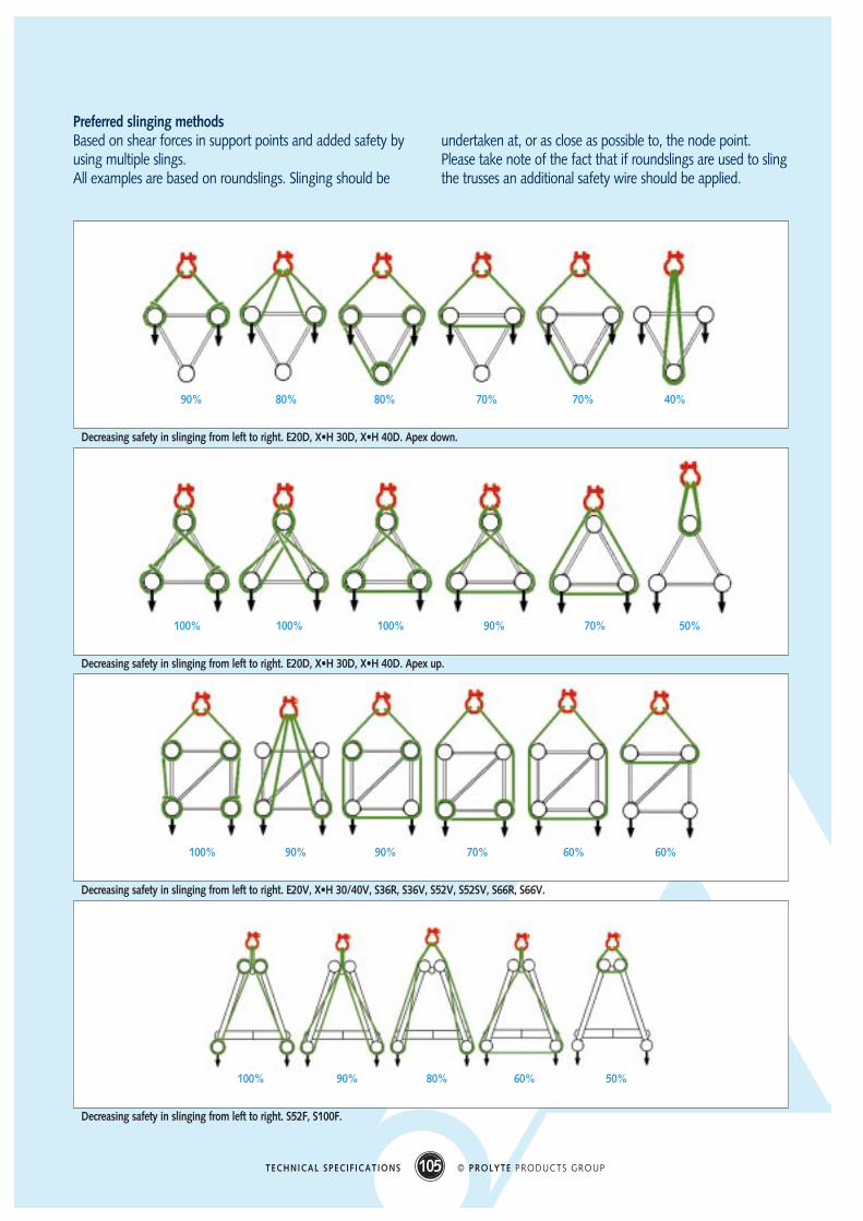
Decreasing safety in slinging from left to right. E20D, X•H 30D, X•H 40D. Apex down.
90% 80% 80% 70% 70% 40%
Decreasing safety in slinging from left to right. E20D, X•H 30D, X•H 40D. Apex up.
Preferred slinging methodsBased on shear forces in support points and added safety byusing multiple slings.All examples are based on roundslings. Slinging should be
undertaken at, or as close as possible to, the node point.Please take note of the fact that if roundslings are used to slingthe trusses an additional safety wire should be applied.
Decreasing safety in slinging from left to right. E20V, X•H 30/40V, S36R, S36V, S52V, S52SV, S66R, S66V.
Decreasing safety in slinging from left to right. S52F, S100F.
100% 100% 100% 90% 70% 50%
100% 90% 90% 70% 60% 60%
100% 90% 80% 60% 50%
106 © PROLYTE PRODUCTS GROUPTECHNICAL SPECIFICATIONS
Miscellaneousa. Measurements of combined grids
with sleeve blocks and corners
1000
626
187
187
DEVIATION FROM STANDARDS STRAIGHTS
T-HOINT HORIZONTAL 40VC017
MPT SLEEVEBLOCK MPT-010
STANDARD STRAIGHT
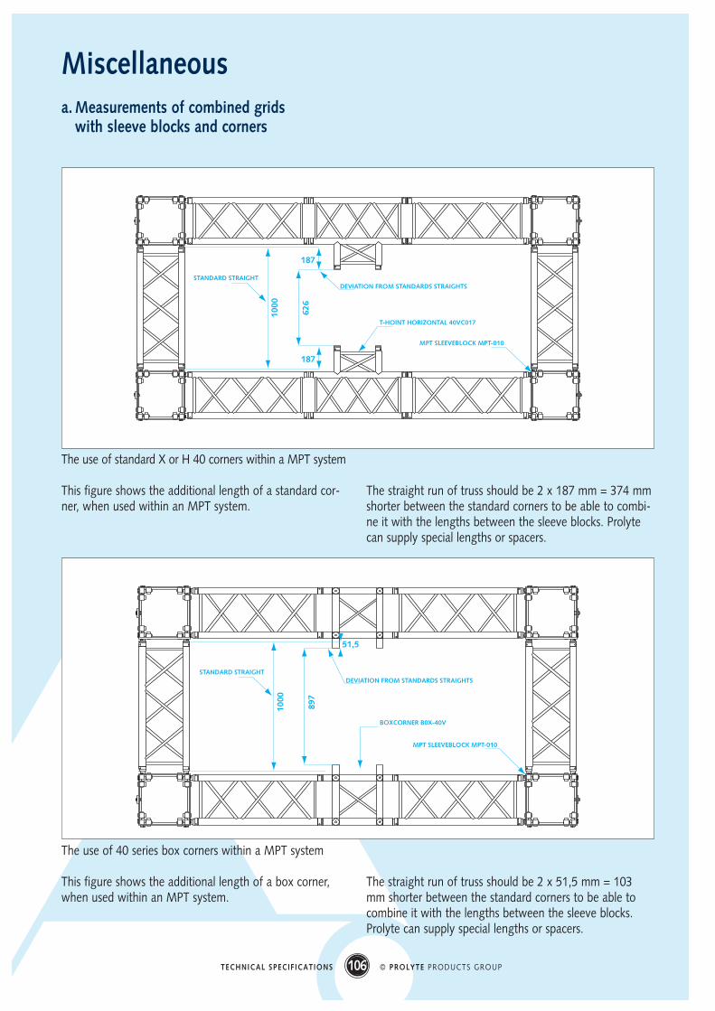
The use of standard X or H 40 corners within a MPT system
This figure shows the additional length of a standard cor-ner, when used within an MPT system.
The straight run of truss should be 2 x 187 mm = 374 mmshorter between the standard corners to be able to combi-ne it with the lengths between the sleeve blocks. Prolytecan supply special lengths or spacers.
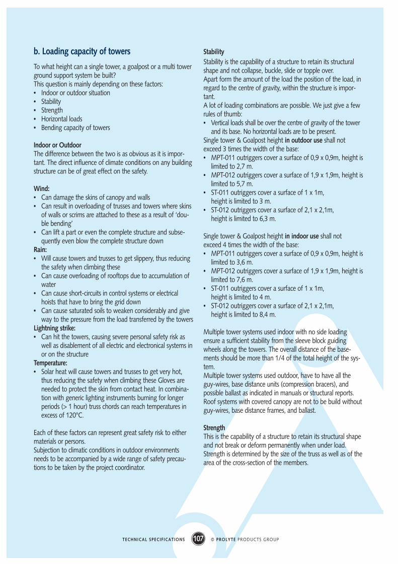
The use of 40 series box corners within a MPT system
This figure shows the additional length of a box corner,when used within an MPT system.
The straight run of truss should be 2 x 51,5 mm = 103mm shorter between the standard corners to be able tocombine it with the lengths between the sleeve blocks.Prolyte can supply special lengths or spacers.
1000
897
DEVIATION FROM STANDARDS STRAIGHTS
BOXCORNER B0X-40V
MPT SLEEVEBLOCK MPT-010
STANDARD STRAIGHT
51,5
107 © PROLYTE PRODUCTS GROUPTECHNICAL SPECIFICATIONS
b. Loading capacity of towers
To what height can a single tower, a goalpost or a multi towerground support system be built?This question is mainly depending on these factors:• Indoor or outdoor situation• Stability• Strength• Horizontal loads• Bending capacity of towers
Indoor or OutdoorThe difference between the two is as obvious as it is impor-tant. The direct influence of climate conditions on any buildingstructure can be of great effect on the safety.
Wind:• Can damage the skins of canopy and walls• Can result in overloading of trusses and towers where skins
of walls or scrims are attached to these as a result of ‘dou-ble bending’
• Can lift a part or even the complete structure and subse-quently even blow the complete structure down
Rain:• Will cause towers and trusses to get slippery, thus reducing
the safety when climbing these• Can cause overloading of rooftops due to accumulation of
water• Can cause short-circuits in control systems or electrical
hoists that have to bring the grid down• Can cause saturated soils to weaken considerably and give
way to the pressure from the load transferred by the towersLightning strike:• Can hit the towers, causing severe personal safety risk as
well as disablement of all electric and electronical systems inor on the structure
Temperature:• Solar heat will cause towers and trusses to get very hot,
thus reducing the safety when climbing these Gloves areneeded to protect the skin from contact heat. In combina-tion with generic lighting instruments burning for longerperiods (> 1 hour) truss chords can reach temperatures inexcess of 120°C.
Each of these factors can represent great safety risk to eithermaterials or persons.Subjection to climatic conditions in outdoor environmentsneeds to be accompanied by a wide range of safety precau-tions to be taken by the project coordinator.
StabilityStability is the capability of a structure to retain its structuralshape and not collapse, buckle, slide or topple over.Apart form the amount of the load the position of the load, inregard to the centre of gravity, within the structure is impor-tant.A lot of loading combinations are possible. We just give a fewrules of thumb:• Vertical loads shall be over the centre of gravity of the tower
and its base. No horizontal loads are to be present.Single tower & Goalpost height in outdoor use shall notexceed 3 times the width of the base:• MPT-011 outriggers cover a surface of 0,9 x 0,9m, height is
limited to 2,7 m.• MPT-012 outriggers cover a surface of 1,9 x 1,9m, height is
limited to 5,7 m.• ST-011 outriggers cover a surface of 1 x 1m,
height is limited to 3 m.• ST-012 outriggers cover a surface of 2,1 x 2,1m,
height is limited to 6,3 m.
Single tower & Goalpost height in indoor use shall notexceed 4 times the width of the base:• MPT-011 outriggers cover a surface of 0,9 x 0,9m, height is
limited to 3,6 m.• MPT-012 outriggers cover a surface of 1,9 x 1,9m, height is
limited to 7,6 m.• ST-011 outriggers cover a surface of 1 x 1m,
height is limited to 4 m.• ST-012 outriggers cover a surface of 2,1 x 2,1m,
height is limited to 8,4 m.
Multiple tower systems used indoor with no side loading ensure a sufficient stability from the sleeve block guidingwheels along the towers. The overall distance of the base-ments should be more than 1/4 of the total height of the sys-tem.Multiple tower systems used outdoor, have to have all theguy-wires, base distance units (compression bracers), andpossible ballast as indicated in manuals or structural reports.Roof systems with covered canopy are not to be build withoutguy-wires, base distance frames, and ballast.
StrengthThis is the capability of a structure to retain its structural shapeand not break or deform permanently when under load.Strength is determined by the size of the truss as well as of thearea of the cross-section of the members.
108 © PROLYTE PRODUCTS GROUPTECHNICAL SPECIFICATIONS
As each truss and tower is different, is it necessary to checkeach structure on these main factors:• Type of loading (UDL, CPL, multiple point loads etc.)• Amount of load(s) applied• Allowable bending moment, highest in the centre of a span
or at the support point of a cantilever or tower. The chordsand the connection parts are the limiting factor for the ben-ding moment.
• Allowable shear force, highest at the position of the sup-ports or at the position of point loads. The dimensioningand positioning of the diagonal bracing is the limiting factorfor the shear force.
Horizontal loadsThis is often an under-estimated type of loading. It can be pre-sent in many forms: wind, projection screens, canopy skins,guy-wires and ropes, etc.In the loading tables the allowable load in a vertical direction isgiven. A simultaneous loading in any other direction to a trussresults in additional bending forces. These can easily lead tooverloading the truss due to bending stresses in one or morechords.For a number of truss types only vertical loading is allowed:S36R, S52F&V, S66R&V and S100F.
When these trusses are side loaded, adequate measures needto be taken to ensure that these loads are absorbed in com-pression (e.g. additional truss) or tension (e.g. wire ropes) bra-cing elements.
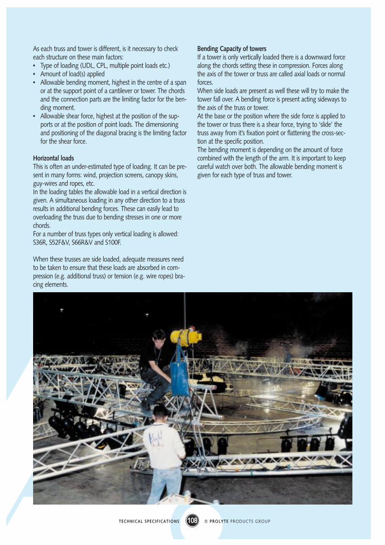
Bending Capacity of towersIf a tower is only vertically loaded there is a downward forcealong the chords setting these in compression. Forces alongthe axis of the tower or truss are called axial loads or normalforces.When side loads are present as well these will try to make thetower fall over. A bending force is present acting sideways tothe axis of the truss or tower.At the base or the position where the side force is applied tothe tower or truss there is a shear force, trying to ‘slide’ thetruss away from it’s fixation point or flattening the cross-sec-tion at the specific position.The bending moment is depending on the amount of forcecombined with the length of the arm. It is important to keepcareful watch over both. The allowable bending moment isgiven for each type of truss and tower.

109 © PROLYTE PRODUCTS GROUPTECHNICAL SPECIFICATIONS
c. Distinction X and H truss
Distinction X & H1. The outer diameter of the X-chords are 51mm (~ 2 inch) and of the H-chords 48 mm (1,889 inch)2. H truss has a 25-30% higher self weight than X truss. 3. H truss has an added second recessed ring in the coupler receiver next to the Prolyte-embossed ring.
Because of the differential in their loading capacities, you should never combine X and H trusses.
H-COUPLER
X-COUPLER
Prolyte manufactures all its trusses with end bracesThis is to prevent any loss of loading capacity if the trusses are incorrectly mounted.
The triangulated shape remains, no matter which way the truss is mounted, due to the end bracing.
HINGED RECTANGULAR SHAPE TRIANGULAR SHAPE
NO END BRACING:UP TO 50% REDUCTION IN STRENGTH
d. Triangular setup and end-braces
110 © PROLYTE PRODUCTS GROUPTECHNICAL SPECIFICATIONS
The European Machine Directive states that; a doubling ofsafety (design) factors is mandatory when persons are lif-ted by, (suspended from, placed upon, climbing), machine-ry structures. It is therefore the complete responsibility ofthe user to establish the actual a required level of safety,when people are lifted by, suspended from, or placed upontruss structures.
This can be done in two ways:• double the amount of weight applied by each person.
Generally, a person’s weight is standardised to 1 kN(app. 100 kg) in static load; thus the calculation factorfor a person will be 2 kN in static (resting) load.Any movement of the person or group of persons (i.e.,dancers) is not included in this factor, but needs carefulconsideration. Movements can lead to dynamic effectsthat exceed the assumed static loads. As a rule ofthumb, assume a factor of two for dynamic loads. Thiswill lead to a calculation factor of 4 kN load per person.
• reduce all data given in the loading tables by 50% whe-never people are to be on the truss. This also results in adoubled design factor.
Apart from this, be sure to take sufficient safety precau-tions. For example: proper horizontal and vertical fall pro-tection and safety lines. When in place, the effect of safetysystems on the truss structure, also needs to be calculatedand checked.
We do not endorse people to climb trusses smaller than 35cm. Apart from the fact that these trusses are so small thatclimbing becomes difficult, most trusses of these dimen-sions are not strong enough to resist forces resulting fromapplied safety lines and fall arrest equipment.
When climbing is necessary to reach panel points in struc-tural steel beams or any other position where risk of fallingis apparent, the venue shall provide a fall protection sys-tem of adequate safety. The same is to be inspected andcertified by an independent and recognised authority.
The climbing riggers themselves shall take care in adequateprecautions by wearing the appropriate type of fall-protec-tion harness, in compliance with international (CE or ANSI)and local regulations
Lifting of persons & Climbing truss
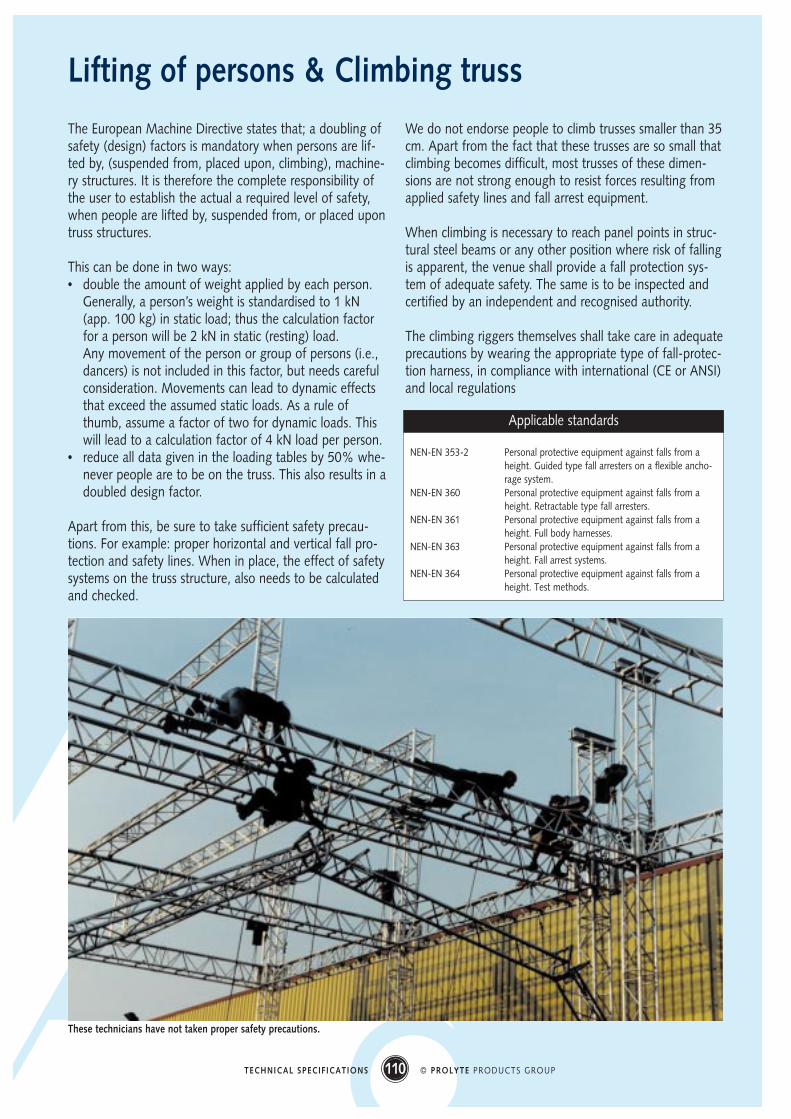
These technicians have not taken proper safety precautions.
NEN-EN 353-2 Personal protective equipment against falls from aheight. Guided type fall arresters on a flexible ancho-rage system.
NEN-EN 360 Personal protective equipment against falls from aheight. Retractable type fall arresters.
NEN-EN 361 Personal protective equipment against falls from aheight. Full body harnesses.
NEN-EN 363 Personal protective equipment against falls from aheight. Fall arrest systems.
NEN-EN 364 Personal protective equipment against falls from aheight. Test methods.
Applicable standards
111 © PROLYTE PRODUCTS GROUPTECHNICAL SPECIFICATIONS
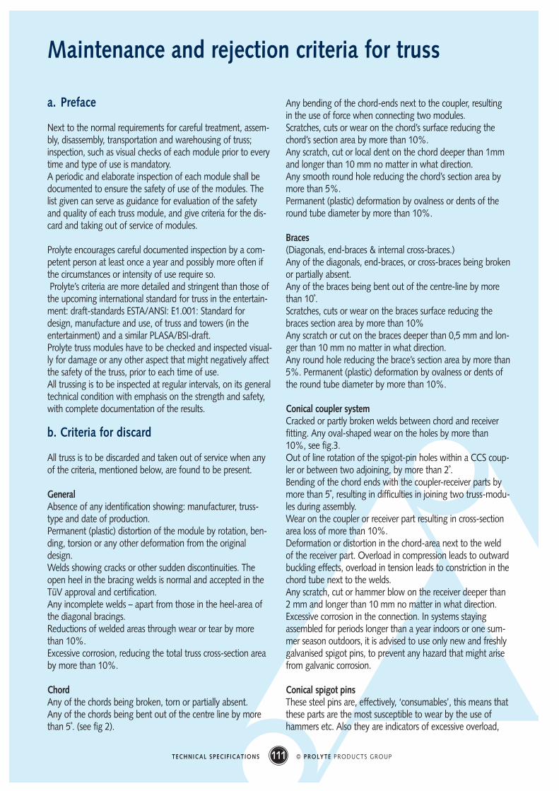
Maintenance and rejection criteria for truss
a. Preface
Next to the normal requirements for careful treatment, assem-bly, disassembly, transportation and warehousing of truss;inspection, such as visual checks of each module prior to everytime and type of use is mandatory.A periodic and elaborate inspection of each module shall bedocumented to ensure the safety of use of the modules. Thelist given can serve as guidance for evaluation of the safetyand quality of each truss module, and give criteria for the dis-card and taking out of service of modules.
Prolyte encourages careful documented inspection by a com-petent person at least once a year and possibly more often ifthe circumstances or intensity of use require so.Prolyte’s criteria are more detailed and stringent than those of
the upcoming international standard for truss in the entertain-ment: draft-standards ESTA/ANSI: E1.001: Standard fordesign, manufacture and use, of truss and towers (in theentertainment) and a similar PLASA/BSI-draft.Prolyte truss modules have to be checked and inspected visual-ly for damage or any other aspect that might negatively affectthe safety of the truss, prior to each time of use.All trussing is to be inspected at regular intervals, on its generaltechnical condition with emphasis on the strength and safety,with complete documentation of the results.
b. Criteria for discard
All truss is to be discarded and taken out of service when anyof the criteria, mentioned below, are found to be present.
GeneralAbsence of any identification showing: manufacturer, truss-type and date of production.Permanent (plastic) distortion of the module by rotation, ben-ding, torsion or any other deformation from the originaldesign.Welds showing cracks or other sudden discontinuities. Theopen heel in the bracing welds is normal and accepted in theTüV approval and certification.Any incomplete welds – apart from those in the heel-area ofthe diagonal bracings.Reductions of welded areas through wear or tear by morethan 10%.Excessive corrosion, reducing the total truss cross-section areaby more than 10%.
ChordAny of the chords being broken, torn or partially absent.Any of the chords being bent out of the centre line by morethan 5˚. (see fig 2).
Any bending of the chord-ends next to the coupler, resultingin the use of force when connecting two modules.Scratches, cuts or wear on the chord’s surface reducing thechord’s section area by more than 10%.Any scratch, cut or local dent on the chord deeper than 1mmand longer than 10 mm no matter in what direction.Any smooth round hole reducing the chord’s section area bymore than 5%.Permanent (plastic) deformation by ovalness or dents of theround tube diameter by more than 10%.
Braces(Diagonals, end-braces & internal cross-braces.)Any of the diagonals, end-braces, or cross-braces being brokenor partially absent.Any of the braces being bent out of the centre-line by morethan 10˚.Scratches, cuts or wear on the braces surface reducing thebraces section area by more than 10%Any scratch or cut on the braces deeper than 0,5 mm and lon-ger than 10 mm no matter in what direction.Any round hole reducing the brace’s section area by more than5%. Permanent (plastic) deformation by ovalness or dents ofthe round tube diameter by more than 10%.
Conical coupler systemCracked or partly broken welds between chord and receiverfitting. Any oval-shaped wear on the holes by more than10%, see fig.3.Out of line rotation of the spigot-pin holes within a CCS coup-ler or between two adjoining, by more than 2˚.Bending of the chord ends with the coupler-receiver parts bymore than 5˚, resulting in difficulties in joining two truss-modu-les during assembly.Wear on the coupler or receiver part resulting in cross-sectionarea loss of more than 10%.Deformation or distortion in the chord-area next to the weldof the receiver part. Overload in compression leads to outwardbuckling effects, overload in tension leads to constriction in thechord tube next to the welds.Any scratch, cut or hammer blow on the receiver deeper than2 mm and longer than 10 mm no matter in what direction.Excessive corrosion in the connection. In systems stayingassembled for periods longer than a year indoors or one sum-mer season outdoors, it is advised to use only new and freshlygalvanised spigot pins, to prevent any hazard that might arisefrom galvanic corrosion.
Conical spigot pinsThese steel pins are, effectively, ‘consumables’, this means thatthese parts are the most susceptible to wear by the use ofhammers etc. Also they are indicators of excessive overload,
112 © PROLYTE PRODUCTS GROUPTECHNICAL SPECIFICATIONS
showing compression-surfaces and bending.Reduction in diameter by more than 10%.Cuts, dents, scratches and other damage to the smooth sur-face of the pin.Burrs, ‘mushrooms’ and other extending sharp edges on thenarrow end of the pin.Deformation by hammering, leading to closure of the safety-clip hole, or screw thread.Loss of zinc coating on any part of the spigot pin, causing it tocorrode.No self-locking nuts shall be used which show clear loss of thenylon-locking mechanism by wear.
c. Documentation
A complete inspection of each truss- or tower module cannotbe executed on a daily basis. However, at least once a year,each truss or tower module should be carefully inspected by aqualified person, (or more often if needed, with respect to theintensity of use), in order to guarantee the technical qualityand safety of the truss-modules. A documentation record ofthis inspection should be kept, registering all details and crite-ria.Each module should be marked with an inspection sticker orother identification mark, being traceable in the files, such as tocomply with local safety regulations concerning lifting applica-tions.When in doubt on technical details or safety aspects alwayscontact the dealer or Prolyte Products.
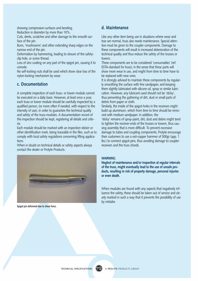
d. Maintenance
Like any other item being use in situations where wear andtear are normal, truss also needs maintenance. Special atten-tion must be given to the coupler components. Damage tothese components will result in increased deterioration of thetechnical quality and thus reduce the safety of the trusses ortowers.These components are to be considered ‘consumables’ (ref.ESTA-standard for truss), in the sense that these parts willshow more wear in use, and might from time to time have tobe replaced with new ones.It is strongly advised to maintain these components by regular-ly smoothing the surface with fine sandpaper, and keepingthem slightly lubricated with silicone oil, spray or similar lubri-cation. However, any lubricant used should not be ‘sticky’,thus preventing the gathering of dirt, dust or small parts ofdebris from paper or cloth.Similarly, the inside of the spigot-holes in the receivers mightbuild up aluminium, which from time to time should be remo-ved with medium sandpaper. In addition, the‘sticky’ remains of spray-paint, dirt, dust and debris might tendto tighten the receiver ends of the trusses or towers, thus cau-sing assembly that is more difficult. To prevent excessivedamage to tubes and coupling components, Prolyte encouragetheir customers to use a red-copper hammer of 500gr (app. 1lbs.) to connect spigot-pins, thus avoiding damage to coupler-receivers and the truss chords.
WARNINGNeglect of maintenance and/or inspection at regular intervalsof the truss, might eventually lead to the use of unsafe pro-ducts, resulting in risk of property damage, personal injuriesor even death.
When modules are found with any aspects that negatively inf-luence the safety, these should be taken out of service and cle-arly marked in such a way that it prevents the possibility of useby mistake.
Spigot pin deformed due to shear force.
113 © PROLYTE PRODUCTS GROUPTECHNICAL SPECIFICATIONS
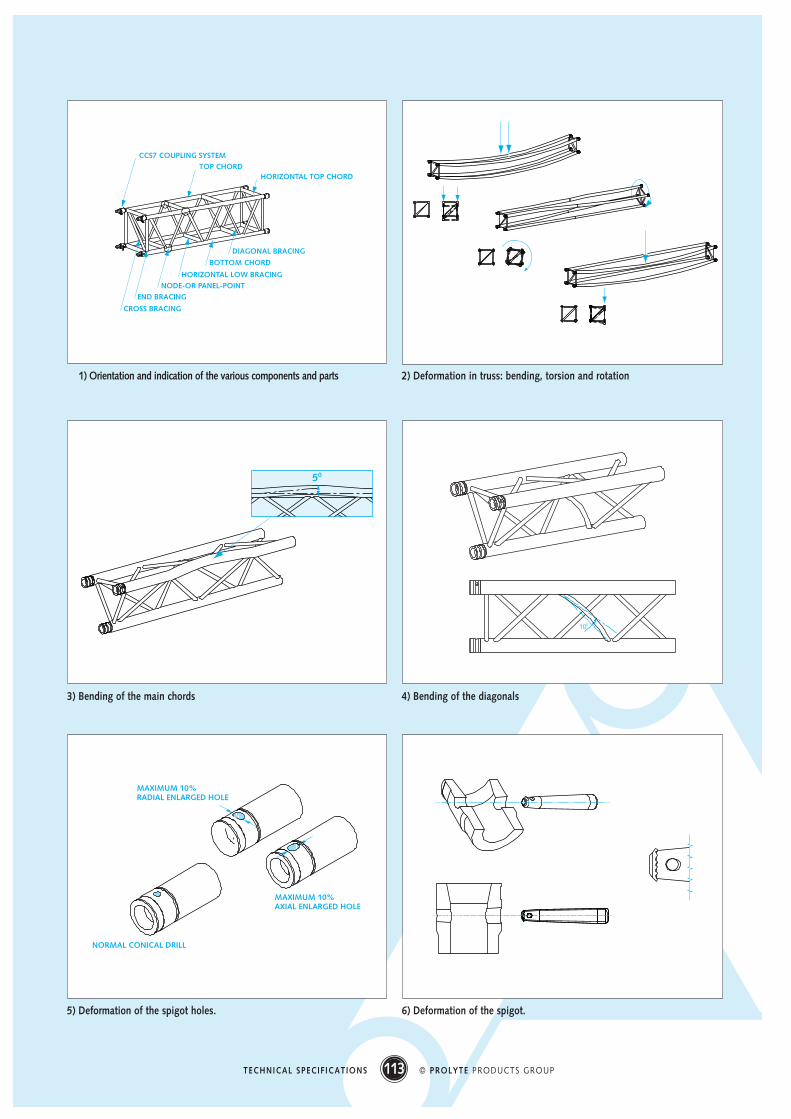
CCS7 COUPLING SYSTEM
CROSS BRACING
TOP CHORD HORIZONTAL TOP CHORD
END BRACING
NODE-OR PANEL-POINT
HORIZONTAL LOW BRACING
BOTTOM CHORD
DIAGONAL BRACING
1) Orientation and indication of the various components and parts 2) Deformation in truss: bending, torsion and rotation
50
100
3) Bending of the main chords 4) Bending of the diagonals
MAXIMUM 10%RADIAL ENLARGED HOLE
MAXIMUM 10%AXIAL ENLARGED HOLE
NORMAL CONICAL DRILL
5) Deformation of the spigot holes. 6) Deformation of the spigot.
114 © PROLYTE PRODUCTS GROUPTECHNICAL SPECIFICATIONS
Code of practise for riggers
Gathering data
Lighting Loads• numbers of the various types of luminaires, ballast’s, follow-
spots (including seats & operators), cables, adaptors etc• weight of each fixture or device• required height of the luminaires, deciding upon the height
of truss or in the case of gantries or ground supports: lengthof upright columns
Sound Loads• numbers of cabinets, flying frames, cables, cabinet suspen-
sion equipment, adaptors etc• weight of each• required height of the speakers, deciding upon the height
of the flying frameScenery / Set Loads• numbers and types of screens, projectors, flying frames,
trolley’s and beams, cables, adaptors etcProjection equipment• id.
Choose trussCalculate the load for each individual truss-runUse the appropriate calculation formulas when combinationsof uniformly distributed loads and point loads are found onone truss. Just adding totals of UDL and concentrated andpoint-loads are not allowed: bending moments in the span canbe seriously affected by the placement of the loads.Note: lighting loads on trusses can roughly be taken as UDL,except for followspot seats, which are to be considered aspoint loads.• Check truss loading with the allowable loading tables of the
truss-types.(bending moment and aluminium alloy allowable stresses tobe derived from the truss-manufacturer)Include in this, the possibility for a point load of at least 100kg + 2 times 50kg at any given point along the truss-run: alighting technician should be able to do maintenance fromthe truss, or replace even the heaviest luminaire.
• Establish the self-weight of the truss-type to be used for thepurpose• length of the truss provides the total weight
(include all parts needed for connections)• self-weight of truss-slings or any similar equipment is not
to be considered
Multiple supports• Establish the number of supports needed to give the truss
spans adequate safety when the amount of weight exceedseither, the allowable weight or span on simple supports ofthe available truss types.
• Calculate the reaction forces from the total of truss + load,by using• formulas for simply supported beams• formulas for continuous beams on more than two sup-
ports
• Establish the lifting capacity of the chain hoist by the foundreaction forces• When lifting people or when technicians climb the grid,
choose hoist types that have at least double the capacityof the amount of the reaction forces found.
• When two or more hoists are lifting the same load, theallowable loading capacity of each hoist shall be no morethan 75% of the capability of the lightest capacity hoist.
• When loads are suspended in overhead situations, anadditional safety device of adequate strength is to beapplied.
Resultant forceCalculate the resultant point loads onto the supporting mainstructure:• In rigging: add the self weight of chain hoist to the reaction
force found, calculate bridle length and wire rope loading,also calculate vertical and horizontal loading on structuralsteel framework.
• In ‘ground building’: add the self weight of the column tothe reaction force found. Check column length against buckling stability; also check overall truss gantry on totalsafety and stability. Add bracing, guy wires or struts wherenecessary.
Check point loads with supporting main structures• In rigging: roof beams, girders and panel point loading
capacities. The data on allowable beam and node pointloading are to be provided by the venue.
• In ‘ground building’: loading capacity on the floor area’s, atruss footprint can be much less than one square metre.The data on allowable floor loading is to be provided by thevenue.
• Corrections for possible overloading situations are to bemade by the rigger in bridling the chain hoists (differently)or by the ‘trusser’ by adding more supports.
115 © PROLYTE PRODUCTS GROUPTECHNICAL SPECIFICATIONS
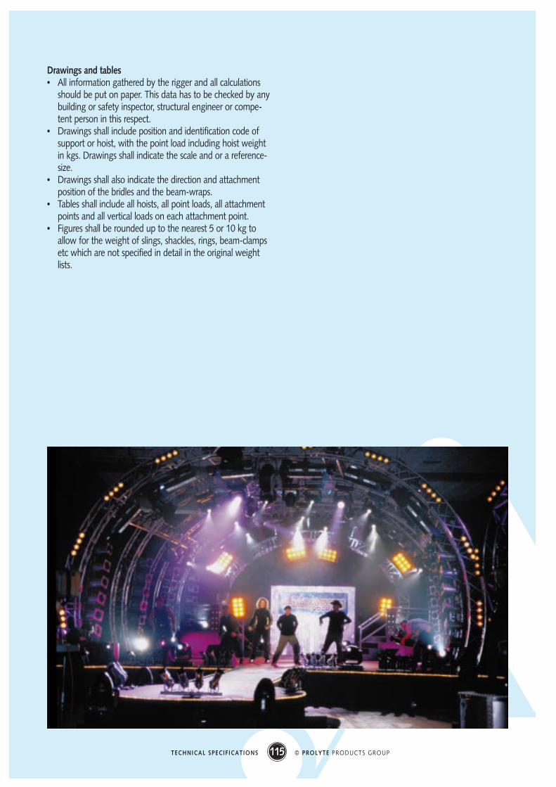
Drawings and tables• All information gathered by the rigger and all calculations
should be put on paper. This data has to be checked by anybuilding or safety inspector, structural engineer or compe-tent person in this respect.
• Drawings shall include position and identification code ofsupport or hoist, with the point load including hoist weightin kgs. Drawings shall indicate the scale and or a reference-size.
• Drawings shall also indicate the direction and attachmentposition of the bridles and the beam-wraps.
• Tables shall include all hoists, all point loads, all attachmentpoints and all vertical loads on each attachment point.
• Figures shall be rounded up to the nearest 5 or 10 kg toallow for the weight of slings, shackles, rings, beam-clampsetc which are not specified in detail in the original weightlists.

116 © PROLYTE PRODUCTS GROUPTECHNICAL SPECIFICATIONS
Temperature:
To convert °C to °F multiply by 1.8 and add 32
To convert °F to °C subtract 32 and multiply by 5/9
Length, Distance and Area Multiply by:
Inches → Centimetres 2.54
Centimetres → inches 0.39
Feet → metres 0.304
Metres → feet 3.28
Yards → metres 0.91
Metres → yards 1.09
Miles → kilometres 1.61
Kilometres → miles 0.62
Acres → hectares 0.40
Hectares → acres 2.47
Square miles → square kilometres 2.59
Square kilometres → square miles 0.39
Weight Multiply by:
Ounces → grams 28.35
Grams → ounces 0.035
Pounds → kilograms 0.45
Kilograms → pounds 2.20
British tons → kilograms* 1016
US tons → kilograms* 907
*) A British ton is 2240 lbs, a US ton is 2000 lbs.
Volume
Imperial gallons → litres 4.55
Litres → imperial gallons 0.22
US gallons → litres 3.79
Litres → US gallons 0.26
Conversion table
More information?Prolyte Products GroupIndustriepark 9, NL-9351 PA Leekphone : +31(0)594 - 851 515fax : +31(0)594 - 851 516e-mail : [email protected]: www.prolyte.com
Related Documents