, 2015 4 Part (A), No. 33, Eng. &Tech.Journal, Vol. 985 Behavior of Reinforced Concrete Flat Plate with Embedded Bearing Plate Dr. Sabih Z. Al-Sarraf Building and Construction Engineering Department, University of Technology/ Baghdad. Dr. Jamal S. Abd Al-Amier Engineering College, University of Al_Mstansiriyah/ Baghdad Dr. Jawad K. Al-Bayati Engineering College, University of Al_Mstansiriyah/ Baghdad Email:[email protected] ABSTRACT This study presents an experimental investigation on the influence of embedded shearhead reinforcement (steel plate) on the punching shear strength of reinforced concrete slabs. This work includes the investigation and testing of one control slab and five scale models of slab-column connection simply supported along the four edges. A shearhead was made by using a steel plate with T-section stiffeners, the stiffeners were fabricated to be with two lines welded on the tension face of the plates. The main variables studied were the dimensions and thickness of the steel plate (used as punching resistance) .The results show that ultimate load capacity at failure increases by (16.48%) over the reference slab. Also, punching shear stress decreases about (29.24%) below the reference slab. Keywords: punching shear, reinforced concrete flat plate, steel plate. ال تصرف المستويةمسلحة اللخرسانية اطات ب المطمورةتحمل ال صفيحة معصة الخ قص تسليح علىحتوي ت التي المستويةطات الب على عمليا بحثا الدراسة ھذه تقدم، يتضمنتسليح ال ھذا.طة الب فيطمورة م حديدية صفائح استخدام يتضمن ال و واحدة سيطرة عتبة فحص خمسة إسن ذاتطات ب ادربعة افھا حوا على بسيط وتكون ت ھذه حديدية مقاطع من مزدوجين بخطين مقواة حديدية صفيحة منطات الب مقطع ذات حرف(T) تجاھين ا لك، الحديديةلصفائح ا وسمك أبعاد تأثير ھيساسية اغيرات المت وكانت المقائص خص بانلنتائج ا اظھرت.لثاقب القص لطة الب مقاومة على سمك تغير نتيجةتأثر تشوھات والت اومة الحديدية الصفيحة وأبعاد، ) بمقدار ازدادتفشل ال عندقصى احمل ال قيمة فأنذلك ك16.48 طة الب عن%( المرجعية و) بمقدار القصدات باجھاقصان ن29.24 المرجعيةطة الب عن%( . INTRODUCTION lat plate structure is a slab and column structure consisting of horizontal and uniform depth slab that transfers loads directly to the columns without the aid of beams or capitals or drop panels. This system is an economical and widely used form especially for multi-storeys residential buildings, also for hotels, motels, apartment houses, hospitals, and dormitories condominium, car parks and office F

Welcome message from author
This document is posted to help you gain knowledge. Please leave a comment to let me know what you think about it! Share it to your friends and learn new things together.
Transcript

, 20154Part (A), No.33,Eng. &Tech.Journal, Vol.
985
Behavior of Reinforced Concrete Flat Plate with Embedded Bearing Plate
Dr. Sabih Z. Al-Sarraf Building and Construction Engineering Department, University of Technology/ Baghdad. Dr. Jamal S. Abd Al-Amier Engineering College, University of Al_Mstansiriyah/ Baghdad Dr. Jawad K. Al-Bayati Engineering College, University of Al_Mstansiriyah/ Baghdad Email:[email protected]
ABSTRACT This study presents an experimental investigation on the influence of embedded shearhead reinforcement (steel plate) on the punching shear strength of reinforced concrete slabs. This work includes the investigation and testing of one control slab and five scale models of slab-column connection simply supported along the four edges. A shearhead was made by using a steel plate with T-section stiffeners, the stiffeners were fabricated to be with two lines welded on the tension face of the plates. The main variables studied were the dimensions and thickness of the steel plate (used as punching resistance) .The results show that ultimate load capacity at failure increases by (16.48%) over the reference slab. Also, punching shear stress decreases about (29.24%) below the reference slab. Keywords: punching shear, reinforced concrete flat plate, steel plate.
مع صفيحة التحمل المطمورة بالطات الخرسانية المسلحة المستويةتصرف ال
الخالصةھذا التسليح يتضمن ،تقدم ھذه الدراسة بحثا عمليا على البالطات المستوية التي تحتوي على تسليح قص
اد بالطات ذات إسن خمسةفحص عتبة سيطرة واحدة و اليتضمن استخدام صفائح حديدية مطمورة في البالطة.البالطات من صفيحة حديدية مقواة بخطين مزدوجين من مقاطع حديدية ھذه تتكونوبسيط على حوافھا األربعة
وكانت المتغيرات األساسية ھي تأثير أبعاد وسمك الصفائح الحديدية ،لكال االتجاھين (T) حرف ذات مقطعاومة والتشوھات تتأثر نتيجة تغير سمك على مقاومة البالطة للقص الثاقب. اظھرت النتائج بان خصائص المق
)% عن البالطة 16.48كذلك فأن قيمة الحمل االقصى عند الفشل ازدادت بمقدار( ،وأبعاد الصفيحة الحديدية .)% عن البالطة المرجعية 29.24نقصان باجھادات القص بمقدار(و المرجعية
INTRODUCTION
lat plate structure is a slab and column structure consisting of horizontal and uniform depth slab that transfers loads directly to the columns without the aid of beams or capitals or drop panels. This system is an economical and widely
used form especially for multi-storeys residential buildings, also for hotels, motels, apartment houses, hospitals, and dormitories condominium, car parks and office
F
Eng. &Tech.Journal, Vol. 33,Part (A), No.4, 2015 Behaviour of Reinforced Concrete Flat Plate with Embedded Bearing Plate
986
buildings. The critical problem in the design of concrete flat plate is the concentration of shear stresses around the column-slab connection which can cause abrupt punching shear failure at loads far below the slab flexural strength. If the design of a slab is found adequate for flexure but not for punching shear, and an increase of the depth or use of higher concrete strength in the whole slab are not desired, the use of shearhead reinforcement is referred to in order to increase the punching shear strength. A shearhead is a separately definable structure embedded in the concrete at the junction, and serves to spread the load of the floor on the respective column and thereby reduces the effect of the vertical forces; i.e., reduces the stress in the slab concrete by increasing the critical punching shear perimeter around the column. In 1961, Moe(1) tested three (150mm) thick slabs in which (19mm) thick steel plate was placed over the column and even with the compression surface of the slab, the plates were intended to increase the effective size of the column. In 1970, Hanson (2) tested three (203mm) thick lightweight concrete slabs. Two of the specimens contained shearheads, and in one of the specimens ducts were located (7.5mm) from the end of the shearhead arm. In 2005, Jawad (3) tested five specimens. The main variables are dimensions of shearhead and plane steel strip welded to the steel channel shape. Also, in 2005, Al-Kerwei (4) presented a theoretical study on one type of shear reinforcement called open wide collar. In 2006, Al-Maiaahei(5), tested fourteen specimens with special embedded shearhead. He tested four types of steel plate (stiffened plate in edge by steel angles with shear connectors distributed on the surface of the steel plate, perforated plate stiffened in edge by steel angles, stiffened plate of parallel steel strips placed vertically and steel angles in edges and finally cross shape with distributed shear connectors. In 2007, Al-Bayati's (6) experimental study included sixteen specimens. The main variables studied were the shape; dimension, thickness and shear connector of steel plate. Also, in 2007,Abd Al-Salam,(7), presented a numerical study of flat plate construction with special embedded shearhead using finite element method. She studied the effect of using steel plate as shear reinforcement with three types of steel plate (square steel plate with shear connectors distributed on the surface of the steel plate, cross shape with distributed shear connectors and a square plate which has rounded edge with distributed shear connectors). In this paper, steel plate shearhead reinforcement with steel shear connector are used to avoid the problem of excessive punching shear stresses. The shearheads used is a plate with stiffeners.
Figure(1) Shearhead Used in the Study.
Eng. &Tech.Journal, Vol. 33,Part (A), No.4, 2015 Behaviour of Reinforced Concrete Flat Plate with Embedded Bearing Plate
987
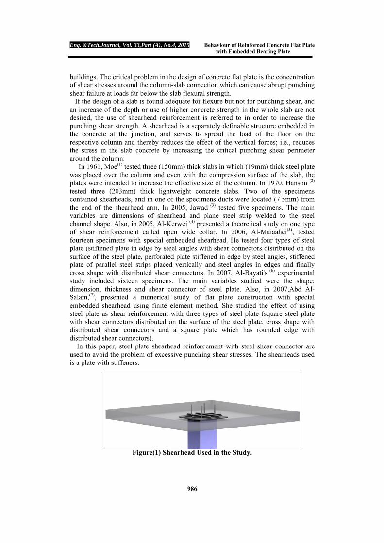
Specimens Details Six medium scale concrete flat plate slabs, were constructed for this study using normal strength reinforced concrete for a square slab (1000×1000mm) in size, with a total thickness of (70mm) and (150×150mm) square stub column with (200mm) height cast monolithically at the centre of the slab. The slab portion of these models was reinforced with deformed wires of (6mm) diameter distributed across the section (75mm c/c) as shown in Fig. (2). Five specimens were made with square steel plate of rounded corners as shearhead reinforcement. Shearhead plate was used with (3mm, 5mm and 8mm) thickness and size were taken to represent the distance from the column face to edge of the plate ( d, 1.5d and 2d) where d is the effective depth of the slab 60mm. The obtained length of the steel plate was as follows, For small plate (S): plate length =2d+150= 2(60)+150= 270 mm Medium plate (M) plate length =2(1.5d)+150=2(90)+150=330 mm Large plate (L) plate length =2(2d)+150=2(120)+150=390 mm Shearhead Details This type was made by using a steel plate with T-section stiffeners (3mm thickness, flange 20 mm width and web 20 mm height), the stiffeners were fabricated to be with two lines welded on the tension face of the plates with (80mm c/c) space between the two lines for each direction, as shown in Fig.(3).
Table (1) Characteristics of the Tested Slabs Specimens Dimensions of Plate (mm)
R _ TS5 270 x 270 x 5 TM3 330 x 330 x 3 TM5 330 x 330 x 5 TM8 330 x 330 x 8 TL5 390 x 390 x 5
Figure (2) Specimen Dimensions Prototype Model
150 mm
200 mm
70 mm
1000 mm
6 mm @ 75 mm c/c
Column
Slab
Shearhead
Shearhead steel plate

Eng. &Tech.Journal, Vol. 33,Part (A), No.4, 2015 Behaviour of Reinforced Concrete Flat Plate with Embedded Bearing Plate
988
8 0 m m
2 0 m m
2 0 m m
AA
S e c t io n A - A
P la t e le n g t h
S t i f f e n e rS t e e l p la t e
Compression Test The machine which was used for compression tests of cylinders and cubes was an (MFL) (300ton) capacity hydraulic universal machine in the structural laboratory in Civil Department, College of Engineering, University of Al-Mustansiriya. Cylinders of (150×300mm) (8) and cubes of (150×150mm) (9) were used to test the compressive strength of concrete. Table (2) shows the results of cylindrical compressive strength tests.
Table (2) Compressive Strength of Tested Slabs
Static Modulus of Elasticity With the same machine that was used for the compression test, cylinders of (150×300mm) (10) were used to test the static modulus of elasticity; the compressmeter used has a gage length of (150mm) and dial gage of (0.002mm) accuracy. The results of static modulus of elasticity are shown in Table (3).
Specimens Cylinder Compressive Strength, fc' (MPa)
R 31.33
TS5 29.77
TM3 29.74
TM5 30.62
TM8 28.87
TL5 29.34
Figure(3) Shearhead Steel Plate Details

Eng. &Tech.Journal, Vol. 33,Part (A), No.4, 2015 Behaviour of Reinforced Concrete Flat Plate with Embedded Bearing Plate
989
Table (3) Static Modulus of Elasticity Values for Tested Slabs
Specimens Measured Static Modulus
of Elasticity (MPa)
Predicted Static Modulus of Elasticity
(ACI 318M-08) = cf4700 (MPa)
R 27.62 26.31 TS5 26.90 25.38 TM3 26.81 26.63 TM5 27.03 26.01 TM8 28.96 25.29 TL5 27.73 25.46
Modulus of Rupture Prisms of (500×100×100mm) (11) were used to test the modulus of rupture, which a load span of (300mm) under two points loading. The results of modulus of rupture are shown in Table (4).
Table (4) Measured and Predicted Values of Modulus of Rupture
Specimens Measured Modulus of Rupture
(MPa) Predicted Modulus of Rupture
(ACI 318M-08) = fc'0.62 (MPa)
R 4.15 3.47
TS5 3.86 3.38
TM3 3.93 3.38
TM5 3.92 3.43
TM8 4.2 3.33
TL5 4.01 3.36
Load Measurement The beam and supporting frame in testing the 1/2-scale models were designed to be sufficiently stiff as shown in Fig.(4) which were attached to the testing machine in compressive strength, the load was measured directly the calibrated machine gage at (4 kN) interval for dial gages.
Figure (4) Preparation for Loading Test Machine.

Eng. &Tech.Journal, Vol. 33,Part (A), No.4, 2015 Behaviour of Reinforced Concrete Flat Plate with Embedded Bearing Plate
990
Concrete
ShrCf-Op 0.2 ShrCf-CI 0.6 UnTensSt 3.9
UnCompSt 30 BiCompSt 0 HydroPrs 0 BiCompSt 0 UnTensSt 0 TenCrFac 0.6
Numerical Applications To study more thoroughly the punching shear behaviour of reinforced concrete slabs with shearhead, a nonlinear finite element analysis has been carried out to analyze all experimentally tested slabs. The analysis is performed by using the finite element models in the finite element package ANSYS 9.0. The elements types and material properties shown in Table (5) were used to model the experimentally tested slabs.
Table (5) Material Properties of the Model Tested Slabs
Element type
Representation Material properties
SOLID65 Concrete
Linear isotropic EX 27467
PRXY 0.2
Multilinear isotropic Strain Stress
Point 1 0.000273 7.5 Point 2 0.000751 18.447 Point 3 0.001229 25.641 Point 4 0.001707 29.11 Point 5 0.0021845 30 Point 6 0.003 30
LINK8
Longitudinal steel
reinforcement and Stirrups
mm6
Linear isotropic
EX 200000 PRXY 0.3
Bilinear isotropic
Yield Stss 483 Tang Mod 10
SOLID45 Loading steel
pad
Linear isotropic
EX 200000 PRXY 0.3
SHELL63 Shearhead
steel plates and Stiffeners
Linear isotropic
EX 200000 PRXY 0.3

Eng. &Tech.Journal, Vol. 33,Part (A), No.4, 2015 Behaviour of Reinforced Concrete Flat Plate with Embedded Bearing Plate
991
Modelling and Meshing of the Tested Slabs Modelling and meshing were used of a quarter of the tested slabs (double symmetry). The model and the shearhead are divided into a number of small elements as shown in Fig. (5) and Fig. (6). Experimental Results and Discussion First Crack In reference specimen (without shear reinforcement), the first crack was observed in the corners of the column sides along the line of the tension reinforcement on the tension surface in the form of flexural cracks about (15.93%) of the ultimate load. The first cracking of all the tested slabs with shear reinforcement was first observed in the tension zone of the slab near one or more of the corners and edges of the steel plate at (16.33-17.37) % of the ultimate load, as shown in Table (5). At this stage of loading, the tensile stress in concrete reached the modulus of rupture value and cracking started in the zone of maximum tensile stress. With further loading, new cracks appeared parallel to the diagonal axis and extended towards the slab edge. At the end of loading stages, all the slabs failed in punching shear as shown in Figures (7) through (12). In general, slabs with punching shear reinforcement (steel plate) had first cracking load greater than the reference specimen. Test results show that, when thickness of the steel plate increases from (3mm to 5mm) for slabs TM3 and TM5 the first cracking load increases from (16.5 kN to 17
Figure(5) Mesh of the Model
Figure (6) Mesh of the shearhead

Eng. &Tech.Journal, Vol. 33,Part (A), No.4, 2015 Behaviour of Reinforced Concrete Flat Plate with Embedded Bearing Plate
992
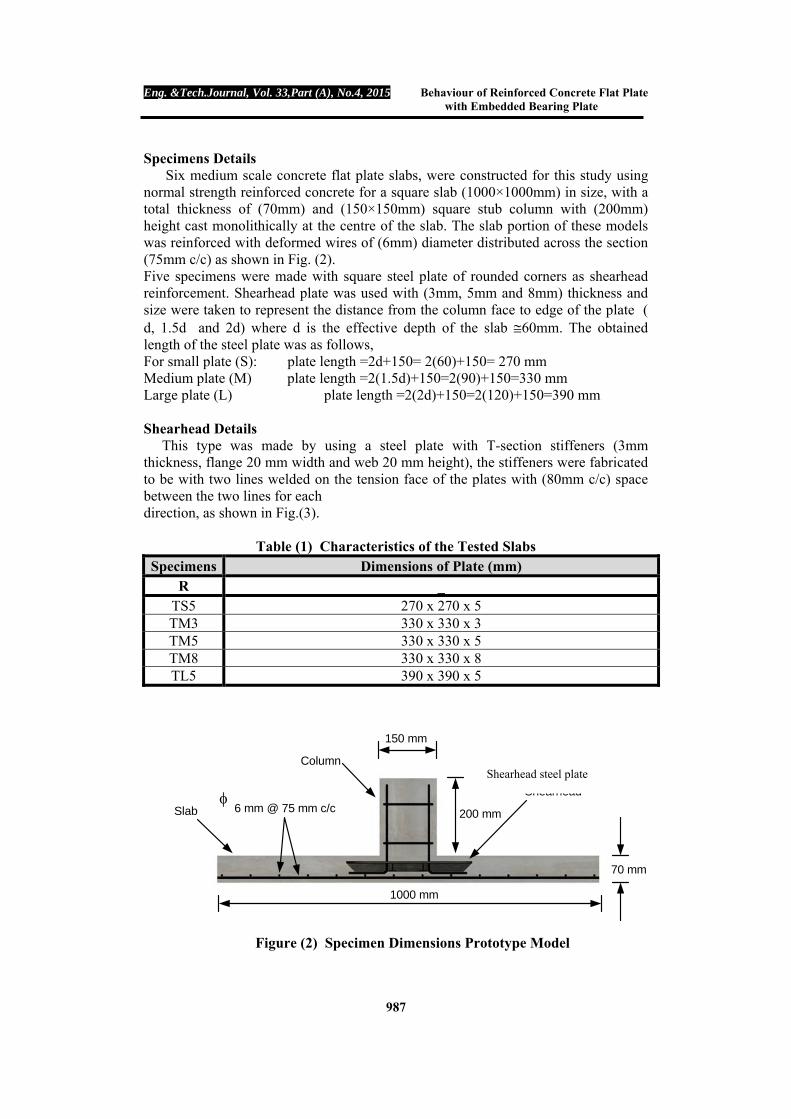
kN) respectively. Also, increasing the thickness from (5mm to 8mm) in TM5 and TM8 increases first cracking load from (17 kN to 18 kN) respectively. Also, the test results show that the increase in the dimensions of the steel plate increases first cracking load from (15 kN to 17 kN) in slabs TS5 (with dimensions 270mm x 270mm) and TM5 (with dimensions 330mm x 330mm) . While, the increase in the dimensions in slabs TM5 (with dimensions 330mm x 330mm) and TL5 (with dimensions 390mm x 390mm) decreases first cracking load from (17 kN to 16 kN). This result because the applied load is distributed on area with relatively large rigidity in slabs TM5. Therefore, the stresses in concrete are small with respect to TL5 and as a result, the tensile stresses in concrete reaches the modulus of rupture value with large loads. Generally, slabs with embedded steel plate have crack width smaller than the reference specimen. Crack widths were measured with special crack measuring instrument having a least width of 0.05mm. At the first stages of loading, the increase in crack width is small with the increase in load until yielding of the steel reinforcement after which the increase in crack width becomes large with small increment of load, and the crack width continues to increase without any appreciable increment in load, as shown in Figures (13) and (14). In general, the test results show that the increase in thickness of steel plate from (3mm) to (5mm), with the same dimensions, in slabs (TM3 and TM5) respectively, decreases the maximum crack width. Also, the increase in thickness of steel plate from (5mm) to (8mm) in slabs (TM5 and TM8 respectively decreases the maximum crack width. It is found that increasing the dimensions of steel plate from (270mm x 270mm) to (330mm x 330mm) for slabs (TS5 and TM5) respectively, increase the maximum crack width. Also, increasing the dimensions of steel plate from (330mm x 330mm) to (390mm x 390mm) for slabs (TM5 and TL5) respectively, increases the maximum crack width.
Table (6) First Cracking and Ultimate Loads
Specimens
First Cracking load (kN)
% Increase in cracking load
Ultimate load (kN)
% Increase in ultimate load
R 14.5 - 91 -
TS5 15 3.45 89 -2.20
TM3 16.5 13.79 95 4.40
TM5 17 17.24 104 14.29
TM8 18 24.14 106 16.48
TL5 16 10.35 98 7.69

Eng. &Tech.Journal, Vol. 33,Part (A), No.4, 2015 Behaviour of Reinforced Concrete Flat Plate with Embedded Bearing Plate
993
Figure(7) Crack Patterns at Tension Side of Slab R
Figure (8) Crack Patterns at Tension Side of Slab TS5
Figure (9) Crack Patterns at Tension Side of Slab TM3
Figure (10) Crack Patterns at Tension Side of Slab TM5
Figure (11) Crack Patterns at Tension Side of Slab TM8
Figure(12) Crack Patterns at Tension Side of Slab TL5
Eng. &Tech.Journal, Vol. 33,Part (A), No.4, 2015 Behaviour of Reinforced Concrete Flat Plate with Embedded Bearing Plate
994
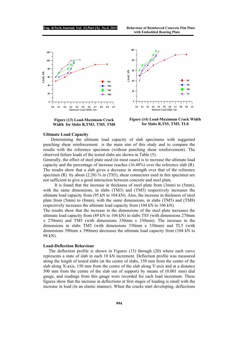
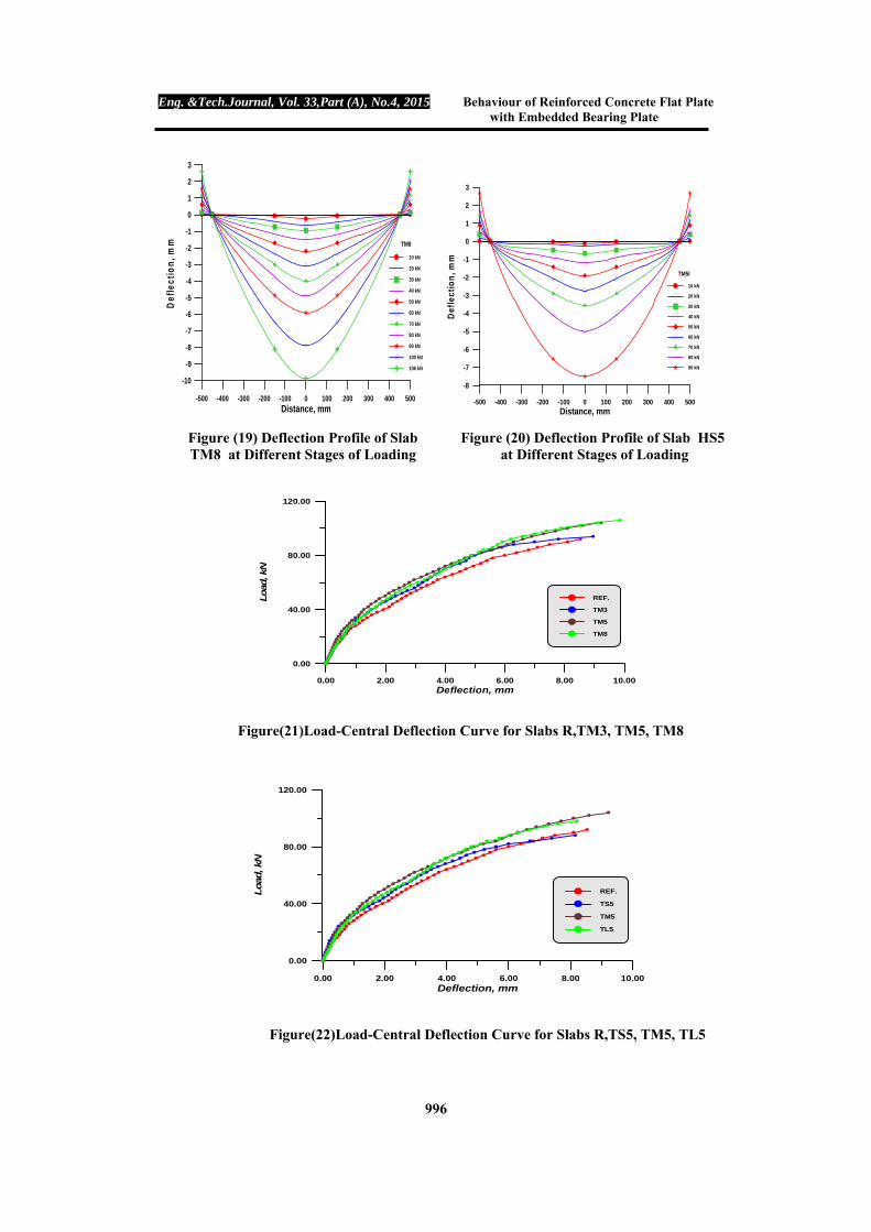
Ultimate Load Capacity Determining the ultimate load capacity of slab specimens with suggested punching shear reinforcement is the main aim of this study and to compare the results with the reference specimen (without punching shear reinforcement). The observed failure loads of the tested slabs are shown in Table (5). Generally, the effect of steel plate used (in most cases) is to increase the ultimate load capacity and the percentage of increase reaches (16.48%) over the reference slab (R). The results show that a slab gives a decrease in strength over that of the reference specimen (R) by about (2.20) % in (TS5), shear connectors used in this specimen are not sufficient to give a good interaction between concrete and steel plate. It is found that the increase in thickness of steel plate from (3mm) to (5mm), with the same dimensions, in slabs (TM3) and (TM5) respectively increases the ultimate load capacity from (95 kN to 104 kN). Also, the increase in thickness of steel plate from (5mm) to (8mm), with the same dimensions, in slabs (TM5) and (TM8) respectively increases the ultimate load capacity from (104 kN to 106 kN). The results show that the increase in the dimensions of the steel plate increases the ultimate load capacity from (89 kN to 104 kN) in slabs TS5 (with dimensions 270mm x 270mm) and TM5 (with dimensions 330mm x 330mm). The increase in the dimensions in slabs TM5 (with dimensions 330mm x 330mm) and TL5 (with dimensions 390mm x 390mm) decreases the ultimate load capacity from (104 kN to 98 kN). Load-Deflection Behaviour The deflection profile is shown in Figures (15) through (20) where each curve represents a state of slab in each 10 kN increment. Deflection profile was measured along the length of tested slabs (at the centre of slabs, 150 mm from the centre of the slab along X-axis, 150 mm from the centre of the slab along Y-axis and at a distance 500 mm from the centre of the slab out of support) by means of (0.001 mm) dial gauge, and readings from this gauge were recorded for each load increment. These figures show that the increase in deflections at first stages of loading is small with the increase in load (in an elastic manner). When the cracks start developing, deflections
0.0 0.1 0.2 0.3 0.4 0.5 0.6 0.7 0.8 0.9 1.0Maximum Crack Width, mm
0
20
40
60
80
100
120
Lo
ad, k
N
Ref.
TM3
TM5
TM8
0.0 0.1 0.2 0.3 0.4 0.5 0.6 0.7 0.8 0.9 1.0Maximum Crack Width, mm
0
20
40
60
80
100
Lo
ad, k
N
Ref.
TS5
TM5
TL5
Figure (13) Load-Maximum Crack Width for Slabs R,TM3, TM5, TM8
Figure (14) Load-Maximum Crack Width for Slabs R,TS5, TM5, TL8

Eng. &Tech.Journal, Vol. 33,Part (A), No.4, 2015 Behaviour of Reinforced Concrete Flat Plate with Embedded Bearing Plate
995
in the slabs increase at a faster rate, and continue to increase without an appreciable increment in load (finally the deflection increases without any additional load and the dial gauge starts to move very rapidly). At the same load level, the deflection in the slab with embedded steel plate is smaller than the deflection in the slab without steel plate because the steel plate increases flexural rigidity of the slab. As a result, the deflection decreases. Figures (21) and (22) represent the load-deflection curves for tested slabs. It is found , when the thickness of the steel plate increases from 3mm in TM3 to 5mm in TM5 the ultimate deflection increases by about (1.21%). Also, increasing the thickness from 5mm in TM5 to 8mm in TM8 increases the ultimate deflection by about (6.93 %). The test results show that the increase in the dimensions of the steel plate increases the ultimate deflection by about (13.11 %) in slabs TS5 (with dimensions 270mm x 270mm) and TM5 (with dimensions 330mm x 330mm). While, the increase in the dimensions of slabs TM5 (with dimensions 330mm x 330mm) and TL5 (with dimensions 390mm x 390mm) decreases the ultimate deflection by about (3.27%).
Figure (15) Deflection Profile of Slab R at Different Stages of Loading
-500 -400 -300 -200 -100 0 100 200 300 400 500Distance, mm
-9
-8
-7
-6
-5
-4
-3
-2
-1
0
1
2
3
Def
lect
ion
, mm REF.
10 kN
20 kN
30 kN
40 kN
50 kN
60 kN
70 kN
80 kN
90 kN
91 kN
-500 -400 -300 -200 -100 0 100 200 300 400 500Distance, mm
-9
-8
-7
-6
-5
-4
-3
-2
-1
0
1
2
Def
lect
ion
, mm
TS5
10 kN
20 kN
30 kN
40 kN
50 kN
60 kN
70 kN
80 kN
89 kN
Figure (16) Deflection Profile of Slab TS5 at Different Stages of Loading
Figure (17) Deflection Profile of Slab TM3 at Different Stages of Loading
Figure (18) Deflection Profile of Slab TM5 at Different Stages of Loading
-500 -400 -300 -200 -100 0 100 200 300 400 500Distance, mm
-9
-8
-7
-6
-5
-4
-3
-2
-1
0
1
2
3
Def
lect
ion
, mm
TM3
10 kN
20 kN
30 kN
40 kN
50 kN
60 kN
70 kN
80 kN
90 kN
95 kN
-500 -400 -300 -200 -100 0 100 200 300 400 500Distance, mm
-10
-9
-8
-7
-6
-5
-4
-3
-2
-1
0
1
2
3
Def
lect
ion
, mm TM5
10 kN
20 kN
30 kN
40 kN
50 kN
60 kN
70 kN
80 kN
90 kN
100 kN
104 kN
Eng. &Tech.Journal, Vol. 33,Part (A), No.4, 2015 Behaviour of Reinforced Concrete Flat Plate with Embedded Bearing Plate
996
-500 -400 -300 -200 -100 0 100 200 300 400 500Distance, mm
-8
-7
-6
-5
-4
-3
-2
-1
0
1
2
3
Def
lect
ion
, mm
TM5I
10 kN
20 kN
30 kN
40 kN
50 kN
60 kN
70 kN
80 kN
90 kN
Figure(21)Load-Central Deflection Curve for Slabs R,TM3, TM5, TM8
Figure(22)Load-Central Deflection Curve for Slabs R,TS5, TM5, TL5
0.00 2.00 4.00 6.00 8.00 10.00Deflection, mm
0.00
40.00
80.00
120.00
Load
, kN
REF.
TM3
TM5
TM8
0.00 2.00 4.00 6.00 8.00 10.00Deflection, mm
0.00
40.00
80.00
120.00
Load
, kN
REF.
TS5
TM5
TL5
Figure (19) Deflection Profile of Slab TM8 at Different Stages of Loading
Figure (20) Deflection Profile of Slab HS5 at Different Stages of Loading
-500 -400 -300 -200 -100 0 100 200 300 400 500Distance, mm
-10
-9
-8
-7
-6
-5
-4
-3
-2
-1
0
1
2
3D
efle
ctio
n, m
m TM8
10 kN
20 kN
30 kN
40 kN
50 kN
60 kN
70 kN
80 kN
90 kN
100 kN
106 kN

Eng. &Tech.Journal, Vol. 33,Part (A), No.4, 2015 Behaviour of Reinforced Concrete Flat Plate with Embedded Bearing Plate
997
Critical Section Perimeter Measurements According to ACI (318-08) (12) and BS (8110-97) (13) codes, the critical section perimeter is assumed to be at (d/2) and (1.5d) from the column face, respectively. For the slabs without steel plate, the critical section perimeter is considered as half the distance (x) between the column face and the end of the actual punching failure surface on the tension side of the slab. While, it is considered as half the distance(x) between the steel plate and the end of the actual punching failure surface for the slabs with steel plate. The calculated distance is based on the measured area. The test results show that, when the thickness of the steel plate increases from (3mm to 5mm) for slabs TM3 and TM5, the critical section perimeter increases by about (0.42%). Also, the test results show that the increase in the dimensions of the steel plate increases the critical section perimeter by about (19.60 %) in slabs TS5 (with dimensions 270mm x 270mm) and TM5 (with dimensions 330mm x 330mm).The increase in the dimensions in slabs TM5 (with dimensions 330mm x 330mm) and TL5 (with dimensions 390mm x 390mm) increases the critical section perimeter by about (9.75 %). In general, it can be noted that the calculated critical section perimeter according BS (8110-97) is better than the ACI (318M-08), based on the comparison with the measured values from the present study.
Table (7) Measured and Calculated Critical Section Perimeters
Specimens
Measured distance of
failure surface x
(mm)
Measured Critical Section
Perimeters * (mm)
% increase critical section
perimeter
Calculated critical section
perimeter# (mm)
Calculated critical section
perimeter " (mm)
R 198 1392 - 828 1284
TS5 133 1612 15.80 1308 1764
TM3 150 1920 37.93 1548 2004
TM5 152 1928 38.50 1548 2004
TM8 146 1902 36.64 1548 2004
TL5 139 2116 52.01 1788 2244
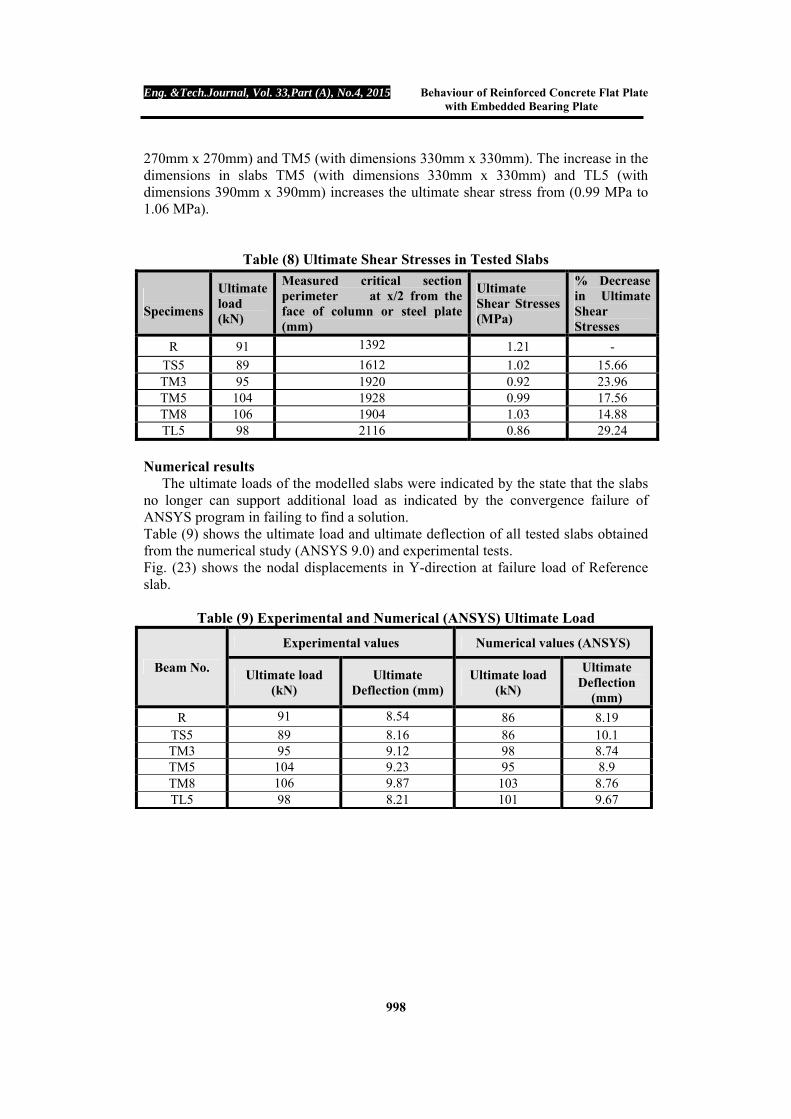
* At x/2 from the face of column or steel plate #At d/2 from the face of column or steel plate "At 1.5d from the face of column or steel plate Shear Stress Characteristics in Tested Slabs: In general, slabs with punching shear reinforcement with respect to the reference specimen (without punching shear reinforcement) can relatively decrease the maximum shear stresses due to increased perimeter of the critical section as shown in Table (8). It is found , that when the thickness of the steel plate increases from 3mm in TM3 to 5mm in TM5 the ultimate shear stress increases from (0.92 MPa to 0.99 MPa). Also, increasing the thickness from (5mm to 8mm) in TM5 and TM8 increases the ultimate shear stress from (0.99 MPa to 1.03 MPa). The test results show that the increase in the dimensions of the steel plate decreases the ultimate shear stress from (1.02 MPa to 0.99 MPa) in slabs TS5 (with dimensions
Eng. &Tech.Journal, Vol. 33,Part (A), No.4, 2015 Behaviour of Reinforced Concrete Flat Plate with Embedded Bearing Plate
998
270mm x 270mm) and TM5 (with dimensions 330mm x 330mm). The increase in the dimensions in slabs TM5 (with dimensions 330mm x 330mm) and TL5 (with dimensions 390mm x 390mm) increases the ultimate shear stress from (0.99 MPa to 1.06 MPa).
Table (8) Ultimate Shear Stresses in Tested Slabs
Numerical results The ultimate loads of the modelled slabs were indicated by the state that the slabs no longer can support additional load as indicated by the convergence failure of ANSYS program in failing to find a solution. Table (9) shows the ultimate load and ultimate deflection of all tested slabs obtained from the numerical study (ANSYS 9.0) and experimental tests. Fig. (23) shows the nodal displacements in Y-direction at failure load of Reference slab.
Table (9) Experimental and Numerical (ANSYS) Ultimate Load
Beam No.
Experimental values Numerical values (ANSYS)
Ultimate load (kN)
Ultimate Deflection (mm)
Ultimate load (kN)
Ultimate Deflection
(mm)
R 91 8.54 86 8.19 TS5 89 8.16 86 10.1 TM3 95 9.12 98 8.74 TM5 104 9.23 95 8.9 TM8 106 9.87 103 8.76 TL5 98 8.21 101 9.67
Specimens
Ultimate load (kN)
Measured critical section perimeter at x/2 from the face of column or steel plate (mm)
Ultimate Shear Stresses (MPa)
% Decrease in Ultimate Shear Stresses
R 91 1392 1.21 -
TS5 89 1612 1.02 15.66 TM3 95 1920 0.92 23.96 TM5 104 1928 0.99 17.56 TM8 106 1904 1.03 14.88 TL5 98 2116 0.86 29.24

Eng. &Tech.Journal, Vol. 33,Part (A), No.4, 2015 Behaviour of Reinforced Concrete Flat Plate with Embedded Bearing Plate
999
Load-Deflection Behaviour Figures (24) to (29) show the experimental and numerical (ANSYS) Load-Central deflection Behaviour of all tested slabs. In general, it can be noted from the Load-Deflection plots that the finite element analysis agrees with the experimental results throughout the entire range of Behaviour. CONCLUSIONS The results show that the increase in thickness of steel plate with the same dimension increased the first cracking load, the ultimate deflection, the ultimate load at failure, the critical section perimeter and the ultimate shear stress and decreased the maximum crack width. The results show that the increase in dimension of steel plate with the same thickness increased the maximum crack width, the critical section perimeter and decreased the ultimate shear stress. Also, increased the first cracking load, the ultimate load at failure and the ultimate deflection when dimension increases from (270 X270mm) to (330 X330 mm) and decreases the first cracking load, the ultimate load at failure and the ultimate deflection when dimension increases from (330 X330mm) to (390X390 mm). Based on the comparison with the measured values from the present study, the calculated critical section perimeter according BS (8110-97) is better than the ACI (318M-08).
Figure (23) Nodal Displacement at Failure Load of Reference Slab R

Eng. &Tech.Journal, Vol. 33,Part (A), No.4, 2015 Behaviour of Reinforced Concrete Flat Plate with Embedded Bearing Plate
1000
0 2 4 6 8 10Deflection, mm
0
20
40
60
80
100L
oad
, kN
REF.
Exp.
Num.
Figure (24) Numerical (ANSYS 9) and Experimental Load-Deflection Behavior for
Slab R
0 4 8 12Deflection, mm
0
20
40
60
80
100
Lo
ad, k
N
TS5
Exp.
Num.
Figure (25) Numerical (ANSYS 9) and Experimental Load-Deflection Behavior
0 2 4 6 8 10Deflection, mm
0
20
40
60
80
100
Lo
ad, k
N
TM3
Exp.
Num.
Figure. (26) Numerical (ANSYS 9) and Experimental Load-Deflection Behavior for Slab TM3
0 2 4 6 8 10Deflection, mm
0
20
40
60
80
100
120L
oad
, kN
TM5
Exp.
Num.
Figure. (27) Numerical (ANSYS 9) and Experimental Load-Deflection Behavior for
Slab TM5
0 2 4 6 8 10Deflection, mm
0
20
40
60
80
100
120
Lo
ad, k
N
TM8
Exp.
Num.
Figure(28) Numerical (ANSYS 9) and Experimental Load-Deflection Behavior for Slab
TM8
0 2 4 6 8 10Deflection, mm
0
20
40
60
80
100
120
Lo
ad, k
N
TL5
Exp.
Num.
Figure (29) Numerical (ANSYS 9) and Experimental Load-Deflection Behavior
for Slab TL5

Eng. &Tech.Journal, Vol. 33,Part (A), No.4, 2015 Behaviour of Reinforced Concrete Flat Plate with Embedded Bearing Plate
1001
REFERENCES [1] Moe, J., "Shearing Strength of Reinforced Concrete Slabs and Footing under Concentrated Load" Portland Cement Association Research and Development Laboratories Bulletin D47, April 1961, PP. 130. [2] Hanson, J. M., "Influence of Embedded Service Ducts on the Strength of Flat Plate Structure", Portland Cement Association Research and Development Bulletin, RD 005.01D, 1970. [3] Jawad, M. K., "Experimental Study on Shearheads in Reinforced Concrete Flat Plates", Ph.D. Thesis, Al-Mustansiriya University, September 2005, PP.1-175 [4] Al-Kerwei, R., H., "Theoretical Study of Open Wide Collar Shearhead Reinforcement Embedded in Flat Plate Construction", M.Sc. Thesis, Civil Engineering Department, Al-Mustansiriya University, July 2005, PP.1-98. [5] Al-Maiaahei, A. N., "Experimental Study of Flat Plate Construction with Special Embedded Shearhead", M.Sc. Thesis, Al- Mustansiriya University, March 2006, PP.1-127 [6] Al-Bayati, H.H.Y., "Experimental Study of Flat Plate Construction with Embedded Shearhead Steel Plates ", M.Sc. Thesis, Al- Mustansiriya University, 2007, PP.1-155. [7] Abd Al-Salam,L. S., " Theoretical Study of Flat Plate Construction with Special Embedded Shearhead Using Finite Element Method ", M.Sc. Thesis, Al- Mustansiriya University, October, 2007. [8] ASTM C39-86, "Test Method for Compressive Strength of Cylindrical Concrete Specimens", ASTM International. [9] BS 1881: Part 116:1983, "Method for Determination of Compressive Strength of Concrete Cube". [10] ASTM C469-87, "Test Method for Static Modulus of Elasticity and Poisson s Ratio of Concrete in Compression" ASTM International. [11] ASTM C78-84, "Test Method for Flexural Strength of Concrete" ASTM International. [12] ACI Code (318M-08) "Building Code Requirement for Structural Concrete and Commentary ", American Concrete Institute, Detroit, , 2008. [13] British Standard Institution (BS 8110), (1997) "Code of Practice for Design and Construction" British Standard Institution Part 1, London.
Related Documents