Standard Operating Procedures !-. Volume J - PIPELINE INTEGRITY ENERGY TRANSFER Facility Risk and 'D'answesfern Pipeline Company Scheduling Assessment Code Reference : Procedure No.: J.09 49 CFR 192.911, 192.917, 192.919, 192.921, 192.935, 192.937, and Effective Date: I Page 1 of 20 192.947 December 15, 2008 1.0 This Standard Operating Procedure (SOP) describes the assessment of risk-related data Procedure in order to identify threats to pipeline facilities. Description 2.0 This SOP provides instructions to gather data relevant to risk assessments, calculate Scope risks, and analyze results. It includes guidelines for reporting, archiving, and re-evaluating criteria. 3.0 This SOP applies to the process of determining the ranking of pipeline segments as it is Applicability used in the integrity management process, prioritization of assessment, prevention, and mitigation. 4.0 Semi-annually: Run company risk assessment software, evaluate Risk Assessment Frequency Algorithms, and evaluates and updates Subject Matter Expert (SME) data Annually: Evaluate software functionality As required: Adjust parameters or algorithms as a result of integrity management activities 5.0 The following table describes the responsibility, accountability, and authority of the Governance operations described in Section 7.0 of this SOP. Function Responsibility Accountability Authority All Operations Pipeline Integrity Principal Codes & Director of Technical Engineer Compliance Engineer Services 6.0 Terms associated with this SOP and their definitions follow in the table below. For Terms and general terms, refer to A. 01 Glossary and Acronyms. Definitions Terms Definitions Baseline Assessment Plan (BAP) The collection of activities, schedules, and results of the assessments required for the initial assessment of an HCA. Integrated Risk Assessment System (IRAS) IRAS is the database used to store the data required to conduct the risk assessment software (RiskAnalyst)

Welcome message from author
This document is posted to help you gain knowledge. Please leave a comment to let me know what you think about it! Share it to your friends and learn new things together.
Transcript

Standard Operating Procedures !-. Volume J - PIPELINE INTEGRITY
ENERGY TRANSFER Facility Risk and 'D'answesfern Pipeline Company Scheduling Assessment
Code Reference : Procedure No.: J.09 49 CFR 192.911, 192.917, 192.919, 192.921, 192.935, 192.937, and Effective Date: IPage 1 of 20 192.947 December 15, 2008
1.0 This Standard Operating Procedure (SOP) describes the assessment of risk-related data Procedure in order to identify threats to pipeline facilities. Description
2.0 This SOP provides instructions to gather data relevant to risk assessments, calculate Scope risks, and analyze results. It includes guidelines for reporting, archiving, and
re-evaluating criteria.
3.0 This SOP applies to the process of determining the ranking of pipeline segments as it is Applicability used in the integrity management process, prioritization of assessment, prevention, and
mitigation.
4.0 Semi-annually: Run company risk assessment software, evaluate Risk Assessment Frequency Algorithms, and evaluates and updates Subject Matter Expert (SME) data
Annually: Evaluate software functionality
As required: Adjust parameters or algorithms as a result of integrity management activities
5.0 The following table describes the responsibility, accountability, and authority of the Governance operations described in Section 7.0 of this SOP.
Function Responsibility Accountability Authority
All Operations Pipeline Integrity Principal Codes & Director of Technical Engineer Compliance Engineer Services
6.0 Terms associated with this SOP and their definitions follow in the table below. For Terms and general terms, refer to A. 01 Glossary and Acronyms. Definitions
Terms Definitions Baseline Assessment Plan (BAP)
The collection of activities, schedules, and results of the assessments required for the initial assessment of an HCA.
Integrated Risk Assessment System (IRAS)
IRAS is the database used to store the data required to conduct the risk assessment software (RiskAnalyst)

Volume J - PIPELINE INTEGRITY Facility Risk Assessments
Procedure No.: J.09Code Reference : 49 CFR 192.911, 192.917, 192.919, 192.921, 192.935, 192.937, and Effective Date: IPage 2 of 20
December 15, 2008192.947
Terms Definitions Integrity Compliance Activity Manager (ICAM)
ICAM is a patented database which is the company's Integrity Management Plan (IMP). It is a tool used by the Pipeline Integrity group to track all integrity compliance activities on company facilities in RCA areas.
7.0 Risk Assessment
This SOP includes the following risk assessment procedures:
• Data Gathering
• Integrating Data
• Baseline Assessment Plan
• Assessment Schedule
• Assessment Schedule Update
• Assessment Schedule Review and Update
• Risk Assessment
• Threat Susceptibility
• Evaluating Results
• Archiving Data
• Re-evaluating
7.1 Corrosion Specialists, GIS, Principal Codes & Compliance Engineer and Pipeline Data Gathering Integrity Engineer use the following process to verify data gathering is performed
properly.
NOTE: Risk data owners are responsible for updating parameters as conditions change. Risk data owners are designated in Appendix B: Parameter Responsibility.
Step Task Done Bv 1 Collects the data needed to calculate risk. Pipeline Integrity Engineer 2 Updates parameters collected specifically for
the company risk assessment software on an annual basis.
Principal Codes & Compliance Engineer
3 Updates pipeline attributes in accordance with SOP B.II Project Documentation and As-Built Process.
GIS Analyst
4 Updates ICAM to verify process is complete. Pipeline Integrity Engineer
7.2 Data integration is performed using the DataView software which displays all pipeline Integrating data to a common pipeline centerline. Users can view each data element with complete Data hierarchy information.
Volume J - PIPELINE INTEGRITY Facility Risk Assessments Procedure No.: J.09 Code Reference :
49 CFR 192.911,192.917,192.919, 192.921,192.935,192.937, and Effective Date: IPage 3 of 20 December 15, 2008192.947
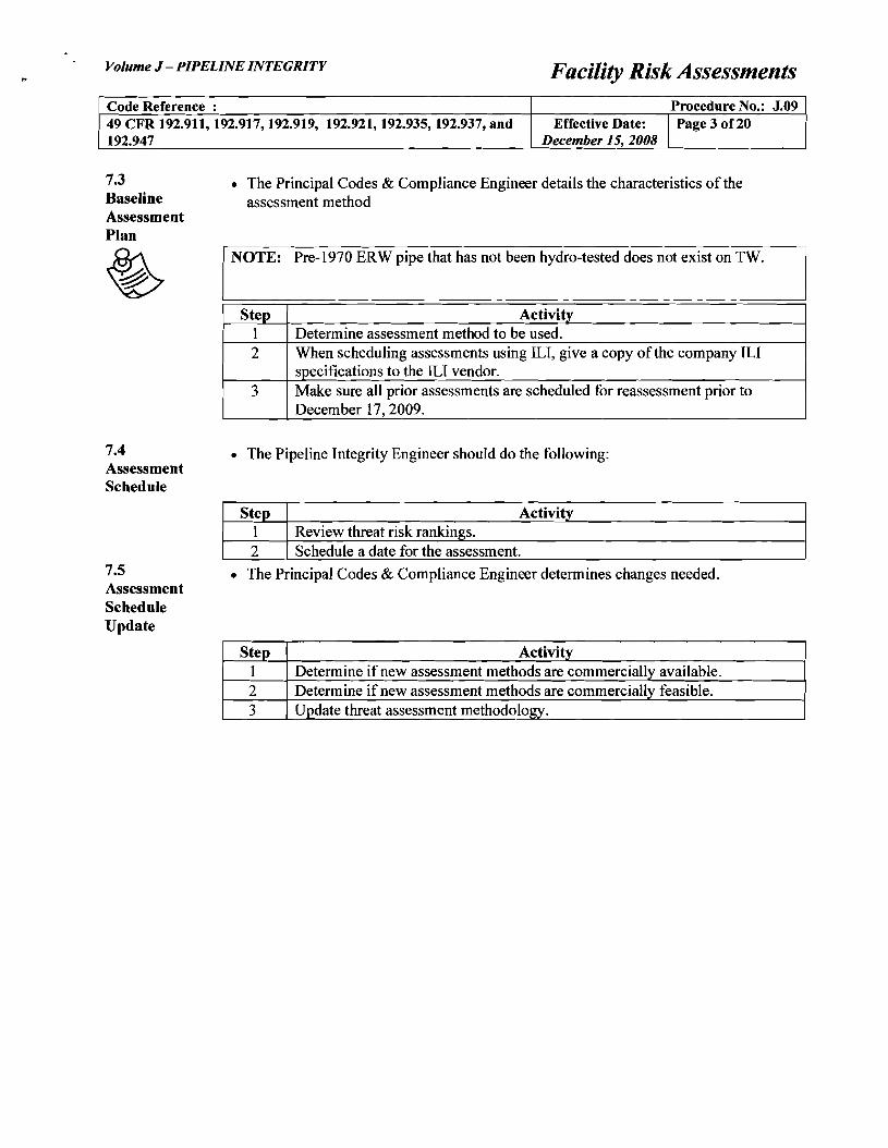
7.3 • The Principal Codes & Compliance Engineer details the characteristics of the Baseline assessment method Assessment Plan
~ NOTE: Pre-1970 ERW pipe that has not been hydro-tested does not exist on TW.
Step Activity 1 Determine assessment method to be used. 2 When scheduling assessments using ILl, give a copy ofthe company ILl
specifications to the ILl vendor. 3 Make sure all prior assessments are scheduled for reassessment prior to
December 17, 2009.
7.4 • The Pipeline Integrity Engineer should do the following: Assessment Schedule
Step Activity 1 Review threat risk rankings. 2 Schedule a date for the assessment.
7.5 • The Principal Codes & Compliance Engineer determines changes needed. Assessment Schedule Update
Step Activity 1 Determine if new assessment methods are commercially available. 2 Determine if new assessment methods are commercially feasible. 3 Update threat assessment methodology.

7.6
Volume J - PIPELINE INTEGRITY Facility Risk Assessments
Code Reference : 49 CFR 192.911, 192.917, 192.919, 192.921,192.935,192.937, and Effective Date:
Procedure No.: J.09 IPage 4 of 20
192.947 December 15, 2008
• The Pipeline Integrity Engineer utilizing the GIS Analysis does the following: Assessment Plan Schedule Review and Update
Step Activity I Detennine if there are any new pipelines with an HCA. 2 Detennine if there is any changes in the size of the PIR 3 Add any new HCA's to the Assessment Plan. 4 Review the new risk rankings. 5 Change dates if necessary. 6 If there are significant changes, utilize MOC to document changes.
7.7 The Pipeline Integrity group uses risk assessment software to: Risk • Detennine system integrity with relative ranking. Assessment
• Run "what-if' scenarios to detennine how certain actions impact risk.
• Establish a Baseline Assessment Plan (BAP).
• Assist with prioritizing expenditures.
NOTE: Contact the Principal Codes & Compliance Engineer for detailed infonnation about accessing or using the company risk assessment software.
Step Activity 1 RUN IRAS DataExchange to import updated data into IRAS database. 2 GENERATE risk results as follows
• Open RiskAnalyst Administrator
• Select "Run Model"
• Select Applicable Pipelines
• Select "Calculate"
3 IMPORT risk scores to Assessment Scheduler 4 UPDATE implementation verification process in ICAM threat/risk.

Volume J - PIPELINE INTEGRITY Facility Risk Assessments
Code Reference : Procedure No.: J.09 49 CFR 192.911, 192.917, 192.919, 192.921,192.935,192.937, and Effective Date: IPage 5 of 20 192.947 December 15, 2008
7.8 The Pipeline Integrity Engineer uses RiskAnalyst to determine segment specific threat Threat susceptibility which is used in choosing the appropriate assessment methodology. Susceptibility
Step Activity 1 DETERMINE threat susceptibility by reviewing threat probabilities in
RiskAnalyst. 2 UPDATE implementation verification process in ICAM threat/risk. 3 IMPORT Threats to Assessment Scheduler.
7.9 The Pipeline Integrity group is responsible for scheduling assessments within the Evaluating Assessment Scheduler software application. Results
Step Activity 1 SELECT the assessment technique(s) for each RCA based on threat
susceptibility using the Assessment Scheduler software program. 2 SCHEDULE integrity assessment based on risk ranking.
NOTE: 1. The Assessment Scheduler software program is located on the Citrix server. Access
Citrix through the Engineering website. Contact local IT personnel for access to Citrix.
2. Scheduling an initial assessment results in establishing a BAP. 3. Subsequent scheduling will produce risk assessment results that must be archived.
Refer to Section 7.6.
3 USE the Assessment Scheduler to maintain BAP reports and to assist with the comparison of RCA managed segments.
7.10 No archiving activities are required as RiskAnalyst stores all historical risk results and Archiving Data raw inputs for each risk run.
7.11 The Pipeline Integrity Engineer is responsible for implementing or facilitating changes Re-evaluating to the risk assessment software and functionality as well as algorithms and parameters.
Step Activity I REVIEW Risk Results with Pipeline Integrity Group. 2 REVIEW Algorithms with Pipeline Integrity Group. 3 REVIEW software functionality with Pipeline Integrity Group and GIS
Group annually.

Volume J - PIPELINE INTEGRITY Facility Risk Assessments
Code Reference : Procedure No.: J.09 49 CFR 192.911,192.917,192.919, 192.921,192.935,192.937, and Effective Date: I Page 6 of 20 192.947 December 15, 2008
8.0 RiskAnalyst results, retained for the life of the facility Documentation Assessment Scheduler Requirements Complete ICAM reporting requirements
9.0 B.II Project Documentation and As-Built Process References

Volume J - PIPELINE INTEGRITY Facility Risk Assessments
Code Reference : Procedure No.: J.09 49 CFR 192.911, 192.917, 192.919, 192.921,192.935,192.937, and Effective Date: IPage 7 of 20 192.947 December 15, 2008
Appendix A: There are no Operator Qualification (OQ) tasks required for this procedure. KSA and OQ Task Table
Volume J - PIPELINE INTEGRITY Facility Risk Assessments
Code Reference : 49 CFR 192.911, 192.917, 192.919, 192.921,192.935,192.937, and Effective Date:
Procedure No.: J.09IPage 8 of 20
192.947 December 15, 2008
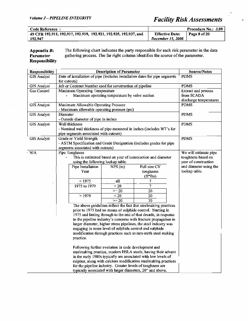
Appendix B: The following chart indicates the party responsible for each risk parameter in the data Parameter gathering process. The far right column identifies the source of the parameter. Responsibility
Responsibility Description of Parameter SourcelNotes GIS Analyst Date of installation of pipe (includes installation dates for pipe segments
for cutouts) PDMS
GIS Analyst Job or Contract Number used for construction of pipeline PDMS Gas Control Maximum Operating Temperature
- Maximum operating temperature by valve section Extract and process from SCADA discharge temperatures
GIS Analyst Maximum Allowable Operating Pressure - Maximum allowable operating pressure (psi)
PDMS
GIS Analyst Diameter - Outside diameter of pipe in inches
PDMS
GIS Analyst Wall thickness - Nominal wall thickness of pipe measured in inches (includes WI's for pipe segments associated with cutouts)
PDMS
GIS Analyst Grade or Yield Strength - ASTM Specification and Grade Designation (includes grades for pipe segments associated with cutouts)
PDMS
N/A Pipe Toughness - This is estimated based on year of construction and diameter
using the following lookup table. Pipe Installation NPS (in) Full size CV
Year toughness (ft*lbs)
< 1975 all 7 1975 to 1979 <20 7
>=20 20 > 1979 <20 20
>=20 30 The above guidelines reflect the fact that steelmaking practices prior to 1975 had no means of sulphide control. Starting in 1975 and lasting through to the end ofthat decade, in response to the pipeline industry's concerns with fracture propagation in larger diameter, higher stress pipelines, the steel industry was engaging in some level of sulphide control and sulphide modification through practices such as rare-earth steel making practice.
Following further evolution in code development and steelmaking practice, modem HSLA steels, having their advent in the early 1980s typically are associated with low levels of sulphur, along with calcium modification steelmaking practices for the pipeline industry. Greater levels of toughness are typicallY associated with larger diameters, 20" and above.
We will estimate pipe toughness based on year of construction and diameter using the lookup table.
Volume J - PIPELINE INTEGRITY Facility Risk Assessments Procedure No.: J.09 Code Reference :
49 CFR 192.911, 192.917, 192.919, 192.921,192.935,192.937, and Effective Date: IPage 9 of 20 December 15 2008192.947
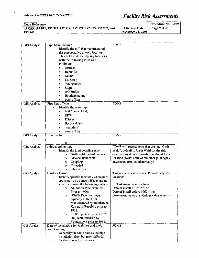
GIS Analyst Pipe Manufacturer PDMS - Identify the mill that manufactured
the pipe installed at each location. This field shall specify any locations with the following mills as a minimum:
• Armco;
• Republic;
• Kaiser;
• US Steel;
• Youngstown;
• Stupp;
• AO Smith;
• Bethlehem; and
• others (list) I
GIS Analyst Pipe Seam Type PDMS - Identify the seam type:
• butt / lap welded;
• ERW
• DSAW;
• flash-welded;
L • "seamless"
• others (list) GIS Analyst Joint Factor PDMS
0
GIS Analyst Joint coupling type PDMS will record items that are not "Girth - Identify the joint coupling type: Weld"; default to Girth Weld for the risk
0 Girth weld (default value) calculations if no information is stored for a 0 Oxyacetalene weld location (Note: none of the other joint types 0 Coupling I have been installed historically) 0 Threaded 0 others (list)
GIS Analyst Hard spot issues This is a yes or no answer. Provide only Yes - Identify specific locations where hard locations
spots may be a concern if they are not identified using the following criteria: If "Unknown" manufacturer:
0 AO Smith Pipe Installed Date of install >=1962 =No Prior to 1960; Date of install before 1962 = yes
0 DSAW Pipe (Le., pipe Date unknown or placeholder value = yes - typically> 16" OD) Manufactured by Bethlehem, Kaiser, or Republic prior to 1961;
0 ERW Pipe (Le., pipe < 20" OD) manufactured by Youngstown prior to 1961.
GIS Analyst Date of installation for Mainline and Field PDMS Joint Coating
- Generally the same date as the pipe installation date, but may differ for locations have been recoated.

Volume J - PIPELINE INTEGRITY Facility Risk Assessments Procedure No.: J.09 Code Reference :
49 CFR 192.911, 192.917, 192.919, 192.921,192.935,192.937, and Effective Date: I Page 10 of20 December 15, 2008192.947
GIS Analyst Coating Type (Mainline) - Mainline coating type (includes
mainline coating types for pipe segments associated with cutouts and recoating)
- Valid entries (to be cross referenced with POMS codelists):
0 Coal Tar Enamel (TGF3) 0 Coal Tar Enamel (TGF4) 0 Asphalt (hot applied) 0 Tape--Single Wrap 0 Tape--Oouble Wrap 0 FBE fusion bonded epoxy 0 Flakeline 0 Wax (hot applied) 0 Wax (cold applied) 0 Mastic (cold applied asphalt) 0 Liquid Epoxy 0 Somastic 0 X-TRU-Coat
POMS
GIS Analyst Coating Type (Field Joint) - Field joint coating (includes field
joint coating types for pipe segments associated with cutouts and recoating)
- At a minimum, the following field joint coating types for FBE mainline coatings shall be identified
0 Field applied FBE 0 Liquid epoxy 0 Cold applied polyethylene
tape with primer 0 Wax tape 0 Liquid polyurethane
SME input only where known. Where not known, a lookup based on year of installation of coating and mainline coating type will be used (supplied by Transwestem).
GIS Analyst Equipment - Locations of the following
equipment: 0 Mainline valves; 0 By-pass valves; 0 Regulators; 0 PSV's; 0 Flange joints; 0 Compressors (discharge
location)
POMS
Volume J - PIPELINE INTEGRITY Facility Risk Assessments
Procedure No.: J.09Code Reference : 49 CFR 192.911,192.917,192.919, 192.921,192.935,192.937, and Effective Date: IPage 11 of 20
December 15, 2008192.947
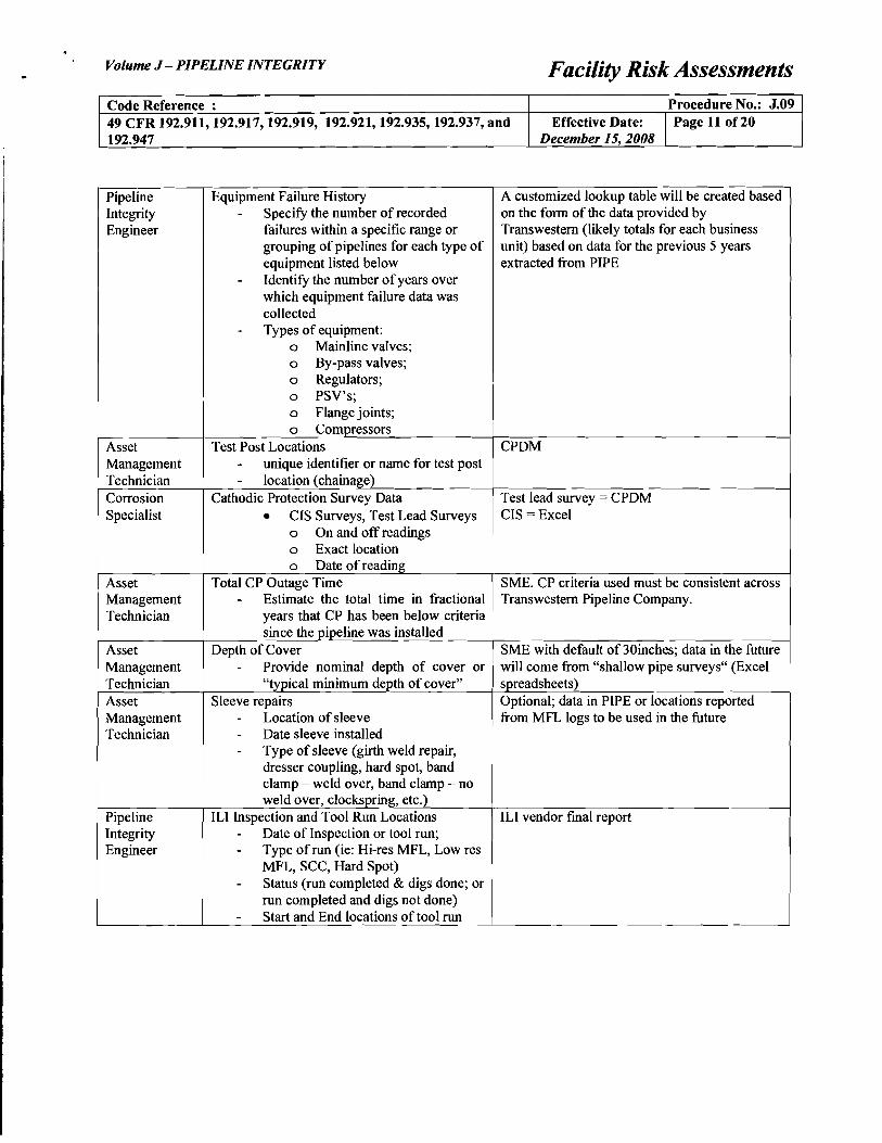
A customized lookup table will be created based Integrity
Equipment Failure History Pipeline on the form of the data provided by
Engineer - Specify the number of recorded
Transwestem (likely totals for each business grouping of pipelines for each type of failures within a specific range or
unit) based on data for the previous 5 years equipment listed below extracted from PIPE
- Identify the number ofyears over which equipment failure data was collected
b~
- Types of equipment: 0 Mainline valves; 0 By-pass valves; 0 Regulators; 0 PSV's; 0 Flange joints; 0 Compressors
Test Post Locations CPDM - unique identifier or name for test post
Technician Management
- location (chainage) Corrosion Cathodic Protection Survey Data Test lead survey = CPDMI
Specialist • CIS Surveys, Test Lead Surveys CIS = Excel 0 On and off readings 0 Exact location 0 Date of reading
Asset Total CP Outage Time SME. CP criteria used must be consistent across Management - Estimate the total time in fractional Transwestem Pipeline Company. Technician years that CP has been below criteria
since the pipeline was installed Asset SME with default of 30inches; data in the future Management
Depth of Cover will come from "shallow pipe surveys" (Excel
Technician - Provide nominal depth of cover or
"typical minimum depth of cover" spreadsheets) Asset Sleeve repairs Optional; data in PIPE or locations reported Management - Location of sleeve from MFL logs to be used in the future Technician - Date sleeve installed
- Type of sleeve (girth weld repair, Idresser coupling, hard spot, band
clamp - weld over, band clamp - no weld over, clockspring, etc.)
Pipeline ILl Inspection and Tool Run Locations ILl vendor fmal report Integrity - Date of Inspection or tool run; Engineer - Type of run (ie: Hi-res MFL, Low res
MFL, SCC, Hard Spot) - Status (run completed & digs done; or I
run completed and digs not done) I - Start and End locations of tool run i
Volume J - PIPELINE INTEGRITY Facility Risk Assessments
Code Reference : Procedure No.: J.09 49 CFR 192.911, 192.917, 192.919, 192.921,192.935,192.937, and Effective Date: IPage 12 of20 192.947 December 15, 2008
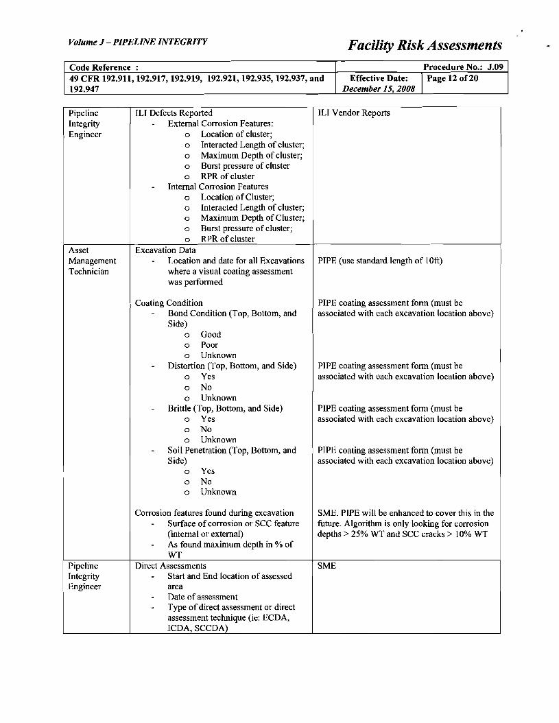
Pipeline Integrity Engineer
ILl Defects Reported - External Corrosion Features:
0 Location of cluster; 0 Interacted Length of cluster; 0 Maximum Depth of cluster; 0 Burst pressure of cluster 0 RPR of cluster
- Internal Corrosion Features 0 Location ofCluster; 0 Interacted Length of cluster; 0 Maximum Depth of Cluster; 0 Burst pressure of cluster; 0 RPR of cluster
ILl Vendor Reports
Asset Management Technician
Excavation Data - Location and date for all Excavations
where a visual coating assessment was performed
Coating Condition - Bond Condition (Top, Bottom, and
Side) 0 Good 0 Poor 0 Unknown
- Distortion (Top, Bottom, and Side) 0 Yes 0 No 0 Unknown
- Brittle (Top, Bottom, and Side) 0 Yes 0 No 0 Unknown
- Soil Penetration (Top, Bottom, and Side)
0 Yes 0 No 0 Unknown
Corrosion features found during excavation - Surface ofcorrosion or SCC feature
(internal or external) - As found maximum depth in % of
WT
PIPE (use standard length of 10ft)
PIPE coating assessment form (must be associated with each excavation location above)
PIPE coating assessment form (must be associated with each excavation location above)
PIPE coating assessment form (must be associated with each excavation location above)
PIPE coating assessment form (must be associated with each excavation location above)
SME. PIPE will be enhanced to cover this in the future. Algorithm is only looking for corrosion depths> 25% WT and SCC cracks> 10% WT
Pipeline Integrity Engineer
Direct Assessments - Start and End location of assessed
area - Date of assessment - Type of direct assessment or direct
assessment technique (ie: ECDA, ICDA, SCCDA)
SME

Volume J - PIPELINE INTEGRITY Facility Risk Assessments
Procedure No.: J.09Code Reference : 49 CFR 192.911, 192.917, 192.919, 192.921,192.935,192.937, and Effective Date: IPage 13 of20
December 15, 2008192.947
GIS Analyst Commissioning Proof Test and Hydrostatic Re-Test
- Identify Start and End location of test section
- Identify minimum test pressure for each test section
- Identify date of test - Type of test (Commissioning Proof
Test or Re-test)
PDMS
Gas Control Pressure cycling - Identify specific locations where
unusually severe pressure cycle magnitudes and/or frequencies have been experienced in the past
Process from SCADA based on difference between daily discharge highs and low. Low is less than 85% ofhigh then it is a yes. Once a yes, it always stays a yes. This is a yes or no answer. Provide only Yes locations
Asset Management Technician
Chemical Inhibition - List segments where a designed
chemical inhibition program is implemented
SME. This is a yes or no answer. Provide only Yes locations
Asset Management Technician
Internal Corrosion Monitoring Programs - List segments where an internal
corrosion monitoring program is in place
- Provide date of last internal inspection
New IC Tracker spreadsheet. No data currently. This is a yes or no answer. Provide only Yes locations
Asset Management Technician
Cleaning Pig Program - List segments where a cleaning
program is implemented
New IC Tracker spreadsheet. No data currently. This is a yes or no answer. Provide only Yes locations
N/Aor Asset Management Technician
Pipeline Product Type - Designate the primary type of fluid
carried by the pipeline. Responses are:
0 Dry natural gas (default) 0 Gas treated with chemical
inhibitor 0 Gas + >0.2 GPM 0 Wet gas
We expect all pipelines to be "Dry Natural Gas". Others will be identified by exception by SME.
Gas Control Gas Composition - mol fraction CO2
- mol fraction H2S - total molecular weight
Typical gas composition can be used as a default value that is loaded for the entire pipeline MARRS (primary), SCADA, or FloGAS
Gas Control Gas flow rate - Volumetric flow rate (ff per day)
SCADA
Asset Management Technician
Pipeline Elevation DEM
Asset Management Technician
Bacteria Count - Estimate the number of bacteria
colonies per mL for a specific pipeline segment.
New IC Tracker spreadsheet. No data currently. Load only areas where colonies per mL are not zero. A zero value will be used as a default value.

Volume J - PIPELINE INTEGRITY Facility Risk Assessments
Code Reference : Procedure No.: J.09 49 CFR 192.911, 192.917, 192.919, 192.921,192.935,192.937, and Effective Date: IPage 14 of20 192.947 December 15, 2008
GIS Analyst
GIS Analyst
GIS Analyst
GIS Analyst
Principal Codes and Compliance Engineer
Class Location - Designation of each segment as:
0 Class 1; 0 Class 2; 0 Class 3; or 0 Class 4
HCA's - Location (start and end chainage) of
HCA - Type ofHCA (Impared Mobility,
Outdoor Area with >= 20 people, Class 3, Class 4)
Environmentally Sensitive Areas - Identify locations of environmentally
sensitive areas Wet Areas
- Locations (start and end chainage) of all "wet" areas, water bodies, and water crossings
Soil Type - USGS soil type classification for all
segments in system - To be used for assessing severity of
soil conditions from perspective of corrosion susceptibility
- Soil type categories in the shapefile to be mapped to suggested lookup values in the following table:
- Bedrock - Cobbles - Clay - Loam/peat - Sand - Water body
Failure History - Incident and Failure history. For each
incident, identify the location, date, associated failure mode and the type of damage incurred.
Associated Failure Mode(s) allowed - Third Party Damage - Internal Corrosion - Stress Corrosion Cracking - Incorrect Operations - External Corrosion
Type of Damage - Rupture - Leak - Hit (3rd Party Damage only) - Hydrotest failure (IC and SCC
only)
PDMS
SSURGO / STATSGO
(State) NLD Note: Weight data in PDMS is insufficient to define these locations. We will need to look at land use data and other sources as an alternative. STATSGO USGS Shape files
Excel spreadsheet and PIPE

· Volume J - PIPELINE INTEGRITY-Code Reference : 49 CFR 192.911, 192.917, 192.919, 192.921,192.935,192.937, and 192.947
History of Girth Weld Anomalies Integrity Engineer GIS Analyist
Pipeline
One Call Requests - The number of one call requests
related to excavations in the pipeline right ofway in 12 month period
GIS Analyist Land Use Types of Land Use (to be confirmed) - Commercial - Industrial - High density residential - Low density residential - Agricultural - Remote - Water crossings (rivers, creeks) - Wetlands
Public One Call Advertising Method Awareness Valid responses: Manager/ - Advertising via direct mail-outs Paradigm and promotion among
contractors (default value) - Advertising via direct mail-outs
and promotion among contractors + Community meetings
-ROW Sign Frequency
Management Asset
Valid responses: Technician - Signs at selected crossings
- Signs at all crossings - All crossings plus intermittently
along route Asset Buried Markers Management Valid responses: Technician - No buried markers (default
value) - Buried markers
Principal One Call Legislation Codes and Valid responses: Compliance - Mandatory Engineer - Mandatory plus civil penalty
- Right-of-way agreement Asset Patrol Frequency (Aerial or ground patrols) Management Valid responses: Technician - Semi-daily patrols
- Daily patrols - Bi-daily patrols (every 2 days) - Weekly patrols - Biweekly patrols (every 2 weeks) - Monthly patrols - Semi-annually patrols - Annually patrols (default value)
Facility Risk Assessments
Procedure No.: J.09 Effective Date: IPage 15 of20
December 15, 2008
SME. This is a yes or no answer. Provide only Yes locations
5MB. One calls counts collected by grid must be reduced to an estimated count related to the pipeline right ofway only - IRTH
NLD. Land use types will be taken from the types of land use identified in the datafile provided by Transwestem.
SME will identify areas that do not have default value
SME
SME
SME will provide a lookup table by State
SME will provide areas where it is not the default value

Volume J - PIPELINE INTEGRITY Facility Risk Assessments
Procedure No.: J.09 Code Reference : 49 CFR 192.911,192.917,192.919, 192.921,192.935,192.937, and Effective Date: IPage 16 of20
December 15, 2008192.947
Asset Management Technician
Locate Request Response Time Valid responses: - Response the same day - Response within two days - Response within three days
SME lookup table by State
N/A Pipeline Locating Methodology Valid responses: - By company records - By magnetic techniques - By pipe locators/probe bars
(default)
Use default value for all pipelines
N/A Pipe Exposure Methodology Valid responses: - Provide route information - Locate/mark - Locate/mark/site supervision - Pipe exposed by hand (default)
Use default value for all pipelines - I don't believe for recoats it is excavated by hand.
Asset Management Technician
Blasting Activity - Estimate the number of blasts per
year within 500ft of pipeline and possible charge to pipe separation distance in ft
SME. When a value for the number of blasts cannot be estimated, 20 blast events/yr will be loaded - this is high
Asset Management Technician
Atmospheric Exposure Valid responses: - Completely above ground - Partially above ground - None (default)
SME for locations that have not been designed to be above ground. L(D,NO) ranges can be loaded with "None" as a default
PDMS for locations that have been designed to be above ground.
Asset Management Technician
Above Ground Facility Accessibility Valid responses: - Above-ground facility adjacent
to roadway - Above-ground facility not
adjacent to roadway
SME. Provide data for locations in at above ground facilities only
Asset Management Technician
Above Ground Facility Protection Valid responses: - Protected by barricade or fence
with no key or other device required to gain access
- Protected by barricade or fence and requires a key or other device to gain access
- Protected by barricade or fence with monitored security cameras and/or a manned site
- Not protected by barricade or fence
SME. Provide data for locations in at above ground facilities only
GIS Analyst / Asset Management Technician
Slab Barriers - Identify where slab barriers of any
kind are located
PDMS

Volume J - PIPELINE INTEGRITY Facility Risk Assessments
Procedure No.: J.09 Code Reference : 49 CFR 192.911, 192.917, 192.919, 192.921,192.935,192.937, and Effective Date: I Page 17 of 20
December 15, 2008192.947
Asset Management Technician
Warning Tape - Identify where warning tape is
located
SME
Public Awareness Manager
Communication program with blasting contractors
- Identify where a heightened communication with blasting contractors is employed (Yes responses only)
SME. This is a yes or no response. Load only Yes responses into the database.
Asset Management Technician
MIC - Identify where MIC has been reported
to be found (Yes responses only)
5MB. This is a yes or no response. Load only Yes responses into the database.
Asset Management Technician
Foreign Line Interference - Identify locations where past
monitoring has confIrmed that interference due to a foreign line impacts a specifIc segment of pipeline.
- Also indicate with a yes or no in a separate column whether this interference has been mitigated.
SME
Asset Management Technician
DC Rail Interference - Identify locations where past
monitoring has confIrmed that interference due to a DC rail line impacts a specifIc segment of pipeline.
- Also indicate with a yes or no in a separate column whether this interference has been mitigated.
SME
Asset Management Technician
AC Interference - Identify locations where past
monitoring has confIrmed that interference due to an AC corridor impacts a specifIc segment of pipeline.
- Also indicate with a yes or no in a separate column whether this interference has been mitigated.
SME
Asset Management Technician
CP Shielding - Identify locations where there is
documented evidence of shielding over a specifIc segment of pipeline (Yes responses only)
5MB. This is a yes or no response. Load only Yes responses into the database.
Asset Management Technician
Telluric Effects - Identify locations where past
monitoring has confIrmed that specifIc segment is prone to strong telluric currents (Yes responses only)
SME. This is a yes or no response. Load only Yes responses into the database.
192.947
Volume J - PIPELINE INTEGRITY Facility Risk Assessments .. Procedure No.: J.09
49 CFR 192.911, 192.917, 192.919, 192.921,192.935,192.937, and Code Reference :
Effective Date: IPage 18 of 20 December 15, 2008
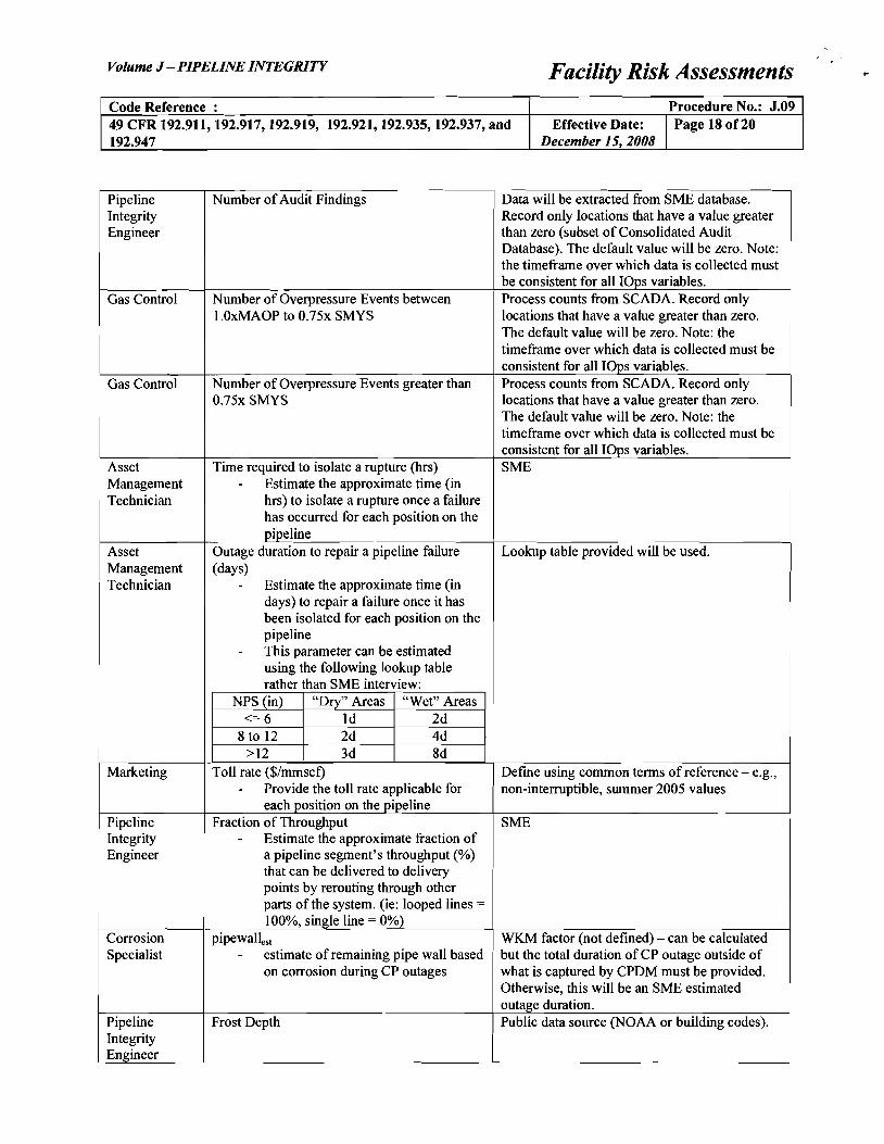
Pipeline Number of Audit Findings Data will be extracted from SME database. Integrity Record only locations that have a value greater Engineer than zero (subset of Consolidated Audit
Database). The default value will be zero. Note: the timeframe over which data is collected must be consistent for all lOps variables.
Gas Control Number of Overpressure Events between Process counts from SCADA. Record only 1.0xMAOP to 0.75x SMYS locations that have a value greater than zero.
The default value will be zero. Note: the timeframe over which data is collected must be consistent for all lOps variables.
Gas Control Number of Overpressure Events greater than Process counts from SCADA. Record only 0.75x SMYS locations that have a value greater than zero.
The default value will be zero. Note: the timeframe over which data is collected must be consistent for all lOps variables.
Asset Time required to isolate a rupture (hrs) SME Management - Estimate the approximate time (in Technician hrs) to isolate a rupture once a failure
has occurred for each position on the pipeline
Asset Outage duration to repair a pipeline failure Lookup table provided will be used. Management (days) Technician - Estimate the approximate time (in
days) to repair a failure once it has been isolated for each position on the pipeline
- This parameter can be estimated using the following lookup table rather than SME interview:
NPS (in) "Dry" Areas "Wet" Areas <=6 Id 2d
8 to 12 2d 4d >12 3d 8d
Marketing Toll rate ($/mmscf) Define using common terms of reference - e.g., - Provide the toll rate applicable for non-interruptible, summer 2005 values
each position on the pipeline Pipeline Fraction of Throughput SME Integrity - Estimate the approximate fraction of Engineer a pipeline segment's throughput (%)
that can be delivered to delivery points by rerouting through other parts of the system. (ie: looped lines = 100%, single line = 0%)
Corrosion pipewallesl WKM factor (not defined) - can be calculated Specialist - estimate of remaining pipe wall based but the total duration of CP outage outside of
on corrosion during CP outages what is captured by CPDM must be provided. Otherwise, this will be an SME estimated outage duration.
Pipeline Frost Depth Public data source (NOAA or building codes). Integrity Engineer

Volume J - PIPELINE INTEGRITY Facility Risk Assessments
Code Reference : 49 CFR 192.911,192.917,192.919, 192.921,192.935,192.937, and Effective Date:
Procedure No.: J.09 IPage 19 of20
192.947 December 15, 2008
Pipeline Integrity Engineer
Asset Management Technician
Asset Management Technician
Asset Management Technician
I Asset Management Technician
Asset Management Technician
Seismic Area or Fault Line
Remediation - None - Monitoring - Stabilization
Unstable slope
Remediation - None - Monitoring - Stabilization
Extreme External Loading
Remediation - None - Monitoring - Stabilization
Susceptibility to Settlement
Remediation - None - Monitoring - Stabilization
Susceptibility to Blasting
Remediation - None - Monitoring - Stabilization
Dynamic Water Environment (erosion)
Remediation - None - Monitoring -
Public data source from OPS. This is a yes or no response. Load only Yes responses into the database.
SME. Records must be associated with locations identified above
SME. This is a yes or no response. Load only Yes responses into the database.
SME. Records must be associated with locations identified above
I
SME. This is a yes or no response. Load only Yes responses into the database.
SME. Records must be associated with locations identified above
SME. This is a yes or no response. Load only Yes responses into the database.
SME. Records must be associated with locations identified above
SME. This is a yes or no response. Load only Yes responses into the database.
SME. Records must be associated with locations identified above
SME. This is a yes or no response. Load only Yes responses into the database.
SME. Records must be associated with locations identified above
I I I
Stabilization I

Volume J - PIPELINE INTEGRITY Facility Risk Assessments
Code Reference : Procedure No.: J.09 49 CFR 192.911,192.917,192.919, 192.921,192.935,192.937, and Effective Date: IPage 20 of20 192.947 December 15, 2008
Pipeline Integrity Engineer
Lightning Strike Frequency
Remediation - None - Monitoring - Stabilization
Public data source (NASA)
SME. Records must be associated with locations identified above
Pipeline Integrity Engineer
Flood Frequency or Flood Severity
Remediation - None - Monitoring - Stabilization
NOAA or STATSGO
SME. Records must be associated with locations identified above
Related Documents