1 Energy Optimization of Bioethanol Production via Hydrolysis of Switchgrass Mariano Martín, Ignacio E. Grossmann 1 Department of Chemical Engineering. Carnegie Mellon University Pittsburgh, PA 15213 Abstract. In this work, we propose the optimal flowsheet for the production of bioethanol from switchgrass, via hydrolysis. A superstructure embedding a number of alternatives is proposed. Two technologies are considered for switchgrass pretreatment, dilute acid and ammonia fibre explosion (AFEX) so that the structure of the grass is broken down. Next, enzymatic hydrolysis follows any of the pretreaments to obtain fermentable sugars, mainly xylose and glucose. Ethanol is obtained by fermentation of the sugars. In order to obtain fuel quality ethanol, water must be removed from the water-ethanol mixture. A number of dehydration technologies is considered including rectification, adsorption in corn grits, molecular sieves and pervaporation. The problem is formulated as an MINLP. The superstructure is optimized by decomposing the MINLP for each of the pretreaments. Then, multieffect columns and heat integration are used to reduce the energy consumption and cooling needs. Finally, an economic evaluation is performed. The optimal flowsheet consists of using dilute acid hydrolysis followed by molecular sieves as dehydration technology, which requires less energy and cooling and yielding a promising production price of 0.8 $/gal. Keywords: Energy, Biofuels, Bioethanol, Mathematical optimization, Hydrolysis, Switchgrass 1 Corresponding author. Tel.: +1-412-268-3642; Fax: +1-412-268-7139. Email address: [email protected] (I.E. Grossmann)

Welcome message from author
This document is posted to help you gain knowledge. Please leave a comment to let me know what you think about it! Share it to your friends and learn new things together.
Transcript
1
Energy Optimization of Bioethanol Production
via Hydrolysis of Switchgrass
Mariano Martín, Ignacio E. Grossmann1
Department of Chemical Engineering. Carnegie Mellon University
Pittsburgh, PA 15213
Abstract.
In this work, we propose the optimal flowsheet for the production of bioethanol from switchgrass, via
hydrolysis. A superstructure embedding a number of alternatives is proposed. Two technologies are considered
for switchgrass pretreatment, dilute acid and ammonia fibre explosion (AFEX) so that the structure of the grass is
broken down. Next, enzymatic hydrolysis follows any of the pretreaments to obtain fermentable sugars, mainly
xylose and glucose. Ethanol is obtained by fermentation of the sugars. In order to obtain fuel quality ethanol,
water must be removed from the water-ethanol mixture. A number of dehydration technologies is considered
including rectification, adsorption in corn grits, molecular sieves and pervaporation. The problem is formulated as
an MINLP. The superstructure is optimized by decomposing the MINLP for each of the pretreaments. Then,
multieffect columns and heat integration are used to reduce the energy consumption and cooling needs. Finally,
an economic evaluation is performed. The optimal flowsheet consists of using dilute acid hydrolysis followed by
molecular sieves as dehydration technology, which requires less energy and cooling and yielding a promising
production price of 0.8 $/gal.
Keywords: Energy, Biofuels, Bioethanol, Mathematical optimization, Hydrolysis, Switchgrass
1 Corresponding author. Tel.: +1-412-268-3642; Fax: +1-412-268-7139. Email address: [email protected] (I.E. Grossmann)
2
Introduccion
The current trend towards environmentally friendly energy sources and the lack of security in fossil fuel
supply has encouraged several governments such as the US and the EU governments to propose policies that
support the use and production of alternative fuels. Thus, ethanol has become the most promising short-term
alternative fuel due to its compatibility with the current car engines and gasoline supply chain1. In order to
increase the use of ethanol, the so called 20-10 plan as well as the Alternative Fuels Standard (AFS) proposes a
large increase in the production of ethanol from corn and lignocellulosic raw materials2 . The EU aims to replace
diesel and gasoline with biofuels by 5.75 % in 2010 and 10 % by 2020 3 .
Together with the large increases in production capacity required by the different policies mentioned
above, and in order to reduce the pressure on food related raw materials, the resources allocated to increase the
production of ethanol are in the direction of developing more efficient processes and the use of different raw
materials. Therefore, the so called second generation of biofuels, and in particular lignocellulosic ethanol, has
gained support due to the high yield from the crop to ethanol, providing a higher net fossil fuel displacement, as
well as in the production process in terms of energy balance and net greenhouse gas (GHG) emissions with a
price far lower than the best estimates using corn as raw material.4,5 Among the different raw materials energy
crops such as switchgrass are gaining support due to the high yield from the ground to ethanol and thus in this
paper we focus on this particular raw material. Currently no production process from lignocellulosic raw materials
is available due to existing technical, economic, and commercial barriers that need to be overcome 6. However,
BRI and Coskata7 industries are already running pilot plants based on fermentation of syngas and planning the
construction of commercial plants in the near future.
Two different production routes can be used to produce ethanol from lignocellulosic switchgrass, either
biomass hydrolysis or biomass gasification. A previous paper by the authors8 proposed an optimized conceptual
production process for the production of bioethanol via gasification of switchgrass with very promising results in
terms of energy consumption and production cost. However, gasification processes have faced some criticism
due to the complexity of the production process and the high capital investment. The hydrolytic path is based on
the hydrolysis of the raw material to break down the structure of the crops into sugars, which are fermented to
3
ethanol. On the one hand, due to its similarity with the current ethanol production processes from corn or sugars,
together with the expected lower investment cost of the plant, it has received increased attention over the last few
years 9-13 . Most of the papers do not consider the pretreatment of the raw material in their analysis or in the
model of the process, and its selection is based on literature review. Recently, Kazi et al. (2010)14 presented a
case study to evaluate different technologies including the pretreatment stage, revealing that dilute acid and
AFEX pretreatments were the most economical ones. On the other hand, the main disadvantage of the hydrolytic
based production of ethanol is the fact that lignin cannot be processed, and thus a part of the carbon source of
the raw material cannot be used to obtain ethanol.
In this paper, we study the production process of ethanol from lignocellulosic raw materials comparing
two hydrolytic pretreatments of the lignocellulosic biomass using mathematical optimization techniques 15,16. We
propose a limited superstructure optimization approach where we first construct a flowsheet embedding the
various process units involved in ethanol production where we consider alternatives for some of the technologies.
These units are interconnected to each other through network flows and other utility streams. The goal is to
optimize the structure minimizing the energy input in the ethanol production process. The optimization of the
system is formulated as a mixed-integer nonlinear programming (MINLP) problem, where the model involves a
set of constraints representing mass and energy balances for all the units in the system. This problem is solved
decomposing the MINLP into two nonlinear programming (NLP) subproblems to determine the structure of the
process flowsheet. We then optimize the distillation columns by using multieffect columns, and finally we perform
a heat integration analysis of the resulting process. The heat recovery network, together with a modified
distillation column design, further reduces the energy consumption and the cooling requirements in the plant.
Finally, an economic evaluation is also performed.
Overall Process Description.
There are a number of pretreatment technologies for the hydrolytic production of ethanol from
lignocellulosic biomass. Several papers present comprehensive reviews of the different technologies that are
available.12,17-22 We can classify the pretreatments into:

4
- Physical pretreatment like grinding, milling or chipping to reduce the size of the raw material. This
stage is used to reduce the crystallinity of the cellulose fibres in the biomass and is highly
dependent on the requirements of the process. Hydrolysis requires small size of the particles to
avoid mass and heat transfer limitations, while gasification is not so demanding.
- Physico-chemical pretreatment such as steam explosion, CO2 explosion or ammonia fibre explosion
(AFEX). To date only AFEX has been applied.
- Chemical pretreatment including the use of ozone, acids, alkali, organic solvents and peroxides.
- Biological pretreatment. Currently, no biological treatment is available since it is a very slow process
that makes in unattractive at an industrial level.
The use of any one of the technologies or a combination of them depends on the raw material since their
effectiveness towards breaking the structure of the biomass depends on the plant itself. Typical lignocellulosic
crops include energy cane, sorghun, miscantus, switchgrass, water hyacinth, municipal solid waste (MSW) and
agricultural residues23. Among them, switchgass is particularly interesting because of its potential for reducing
emissions and its high yield towards ethanol24-27
Grinding is the first stage to reduce the size of the raw material and to increase the contact area for any
other pretreatment. Next, in order make the sugar containing polymers accessible to the enzymes, two methods
have been found to be competitive for industrial production of ethanol from hydrolysis of switchgrass due to the
high yield toward the liberation of cellulose and hemicelluloses from the matrix of the crop: (1) dilute acid (H2SO4)
pretreatment 3,11,13,28 , and (2) ammonia fiber explosion (AFEX)18, 29,30 . This last method loses effectiveness in
lignocellulosic materials like newspaper or aspen chips due to the lignin content and plant structure. Both
pretreatments are considered in the model.
Once the physical structure of the switchgrass has been broken to allow the contact between the
polymers and the enzymes, hydrolysis of the polymeric sugar takes place. This process is carried out in stirred
tank reactors at 45-50 ºC for 3 days where the accessible cellulose and hemicellulose are broken into
fermentable sugars 3, 9,11,31,32.
5
Next, the sugars, mainly glucose and xylose, are fermented into ethanol. The reactions are different in
terms of yield and kinetics. The optimal conditions are 28-38 ºC so that both are fermented at the same time for a
day. A number of different products are obtained together with ethanol, such as different acids products of the
metabolic paths of the microorganisms used (Z. mobilis bacterium) as well as cells are grown 3,11,32.
Figure 1.- Superstructure of the ligno - ethanol production plant via hydrolysis
The separation stages start with the removal of solids, lignin and cells from the liquid slurry coming out of
the fermentor using a mechanical separator. The lignin can be used to obtain energy for the process. Finally, in
order to achieve fuel grade ethanol, water from the ethanol-water mixture must be removed. A distillation column
will remove most of the water. Next, we propose a superstructure similar to the one in a previous work by the
authors8 . Four possibilities are presented, rectification column, adsorption in corn grits, molecular sieves and
pervaporation. Rectification and corn adsorption cannot produce fuel quality ethanol by themselves, thus, the
exiting streams will feed either the molecular sieves or the pervaporation membranes. Figure 1 shows the
flowsheet with the different alternatives.
Mathematical modelling.
All the operations in the bioethanol production process are modeled using short–cut models consisting of
mass and energy balances and design correlations. The model is written in terms of the total mass flows,
component mass flows, component mass fractions, and temperatures of the streams in the network. These are
the main variables whose values have to be determined from the optimization. The components in the system
include those present in the switchgrass, plus those produced during the process of ethanol production, and
belong to the set J = { Water, Ethanol, H2SO4, CaO, Ammonia, Protein, Cellulose, Hemi-Cellulose, Glucose,
Xylose, Lignin, Ash, CO2, O2, Cells, Glycerol, Succinic acid, Acetic acid, Lactic acid, gypsum}. The different units
in the superstructure are modelled as described below, but for the sake of reducing the length of the paper we
refer the reader to the supplementary material for the actual equations.

6
Pretreatment
In order for the fermentation to be effective, the bacteria must be able to reach the cellulose and
hemicellulose. Any lignocellulosic raw material is created with a matrix of lignocellulose that protects the plant and
maintains the structure. As it can be seen in Figure 2, inside the structure of the lignin, the hemicelluloses and the
cellulose constitutes the structure of the plant. This structure must be broken so that the polymers of sugar
(cellulose and hemicellulose) can be attacked. The feed is washed and the size of the switchgrass is reduced by
grinding so that further pretreatments are more effective 12,33. Both stages, washing and grinding, are considered
only in terms of energy consumption (45kWh/ton 33 ) and cost analysis since they do not change the properties of
the feedstock. Next, the two alternatives indicated above, dilute acid pretreatment and AFEX, are analyzed due to
their high capability to degrade this structure18,23.
Figure 2.- Lignocellulosic structure
Amonia fiber explosion (AFEX) Figure 3 shows a detail of the AFEX pretreatment. This method consists of treating the lignocellulosic
material at a mild temperature and high pressure with ammonia to break the physical structure of the crop. In
order to reduce the cost, the ammonia remaining in the slurry after the expansion should be recovered and the
slurry of biomass and water is sent to enzymatic treatment to break the polymers containing sugars18, 29, 30 . The
pretreatment is modeled using the following assumptions.
Ammonia is added in a ratio of 1 kg ammonia /kg of biomass based on the results by Sun & Cheng
200218. Water is also needed at a ratio of 0.6 kg water per kg biomass 18,29,30. The mixture is heated up to the
operating temperature of 105 º C in heat exchanger 1 and fed to the reactor. The residence time in the reactor is
5 min at 20 atm, and next the pressure is released and the content of the reactor discharged to a blowdown tank.
Since the reactor operates in batch mode, at least two reactors in parallel are fed into an intermediate storage
tank to ensure continuous operation. 18, 34 Next, the ammonia remaining in the slurry, around 10% of the initial
amount, is recovered by distillation at high pressure (15atm).14 The distillate is at 40ºC and the bottoms at
200ºC14 and we assume a reflux ratio of 2. The evaporated ammonia is compressed, condensed and mixed with

7
the ammonia recovered in the distillation column and reused again. This is the key point in the economics of this
process. Following these stages, we assume that all of the ammonia is recovered. However, the traces that may
be left, typically below 0.5%34, and they are used as nutrients for the fermentation. Thus we do not consider the
traces in this model.
Figure 3.-Flowsheet for AFEX pretreament
According to the literature 9,18,29 AFEX pretreatment liberates 92% of the glucose and 70% of the Xylose
from switchgrass making it effective for the hydrolysis step. However, AFEX performance loses its efficiency for
lignin content above 10%18 making it unattractive for other raw materials. We assume that after the pretreatment
the monomer of glucose is generated. It will not be the molecule of glucose until the hydrolysis in which the
monomer is hydrated, but for the sake of reducing the number of components we assume that what is generated
is glucose.
Dilute acid
Figure 4 shows part of the flowsheet for dilute acid pretreatment. Dilute acid treatment consists of putting
into contact the lignocellulosic material with a dilute solution of sulfuric acid. A solution of sulfuric acid is mixed
with the biomass and later heated up with steam up to 180 ºC and 12 bar. The final concentration of acid in the
water is fixed to be 1.2 % w/w which is obtained considering the condensed water from the steam together with
the water coming from the previous stage, tank 1. The source of fresh water from Src3 as well as in the form of
steam, Src4, are calculated to verify the energy balances and water requirements in the process. In Reactor 2
the residence time is 30 min28 . Next a flash evaporation of water (Flash 1) reduces the amount of water in the
slurry and provides energy for the process. The slurry is separated in a mechanical centrifuge (Mec Sep 1). The
liquid stream is treated with lime, CaO, to adjust the pH to the one needed in the hydrolysis (Reactor 3) 3, 11, 13, 28
It is reported that lime is the cheapest chemical for this reaction due to the low cost of CaO and also because the
precipitation of gypsum (CaSO4) which allows its easy separation from the liquid 35 The residence time in Reactor
3 is 10 min. Neutralization reactions are exothermic, heating up the exiting stream from reactor 3. CaSO4
(gypsum) precipitates and it can be easily recovered from the liquid stream by filtration (Filter 1). Gypsum can be
8
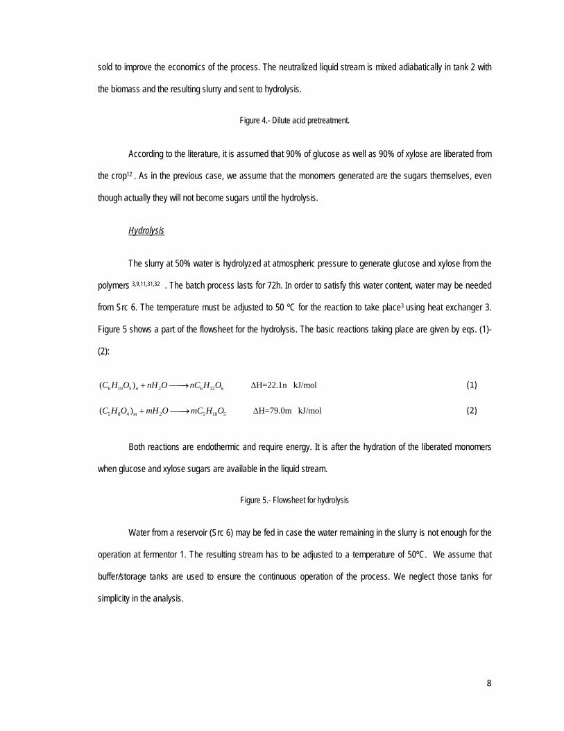
sold to improve the economics of the process. The neutralized liquid stream is mixed adiabatically in tank 2 with
the biomass and the resulting slurry and sent to hydrolysis.
Figure 4.- Dilute acid pretreatment.
According to the literature, it is assumed that 90% of glucose as well as 90% of xylose are liberated from
the crop12 . As in the previous case, we assume that the monomers generated are the sugars themselves, even
though actually they will not become sugars until the hydrolysis.
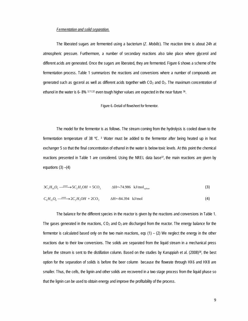
Hydrolysis
The slurry at 50% water is hydrolyzed at atmospheric pressure to generate glucose and xylose from the
polymers 3,9,11,31,32 . The batch process lasts for 72h. In order to satisfy this water content, water may be needed
from Src 6. The temperature must be adjusted to 50 ºC for the reaction to take place3 using heat exchanger 3.
Figure 5 shows a part of the flowsheet for the hydrolysis. The basic reactions taking place are given by eqs. (1)-
(2):
6 10 5 2 6 12 6( ) H=22.1n kJ/molnC H O nH O nC H O (1)
5 8 4 2 5 10 5( ) H=79.0m kJ/molmC H O mH O mC H O (2)
Both reactions are endothermic and require energy. It is after the hydration of the liberated monomers
when glucose and xylose sugars are available in the liquid stream.
Figure 5.- Flowsheet for hydrolysis
Water from a reservoir (Src 6) may be fed in case the water remaining in the slurry is not enough for the
operation at fermentor 1. The resulting stream has to be adjusted to a temperature of 50ºC. We assume that
buffer/storage tanks are used to ensure the continuous operation of the process. We neglect those tanks for
simplicity in the analysis.
9
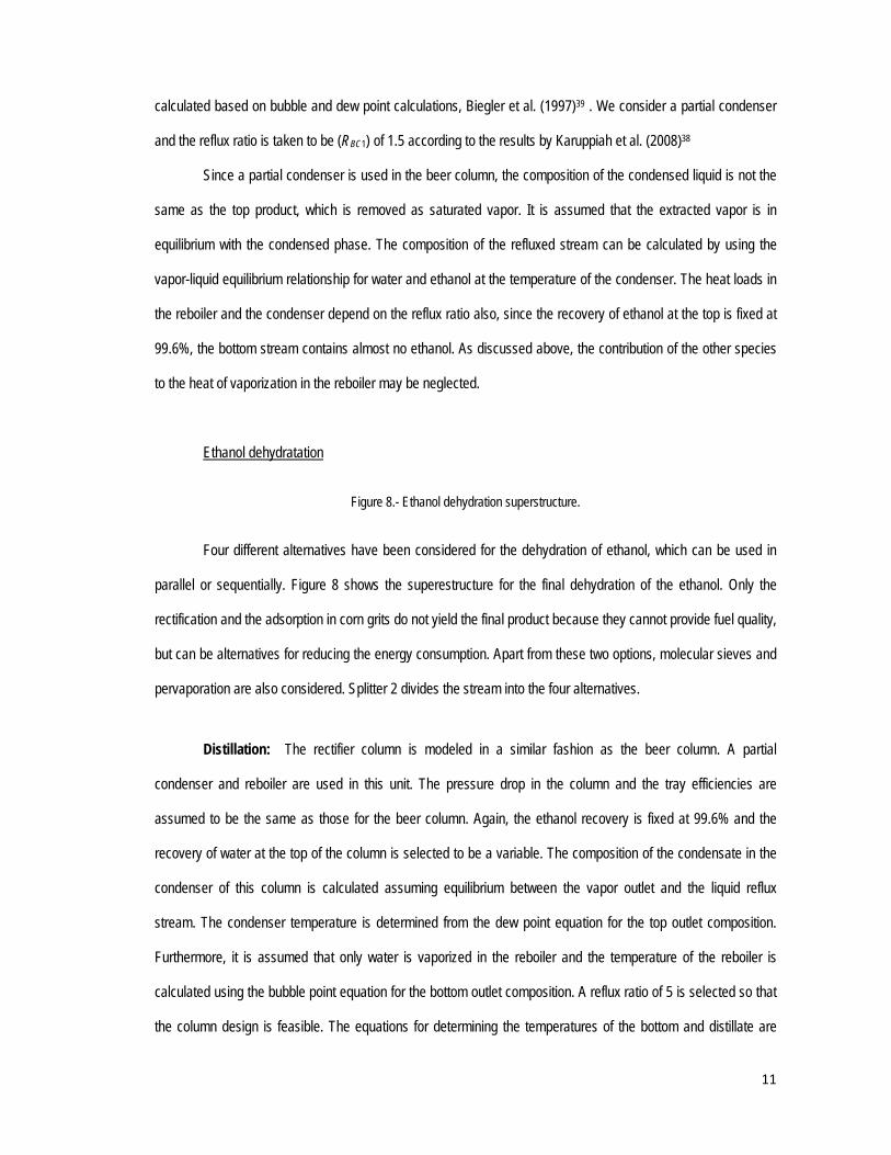
Fermentation and solid separation.
The liberated sugars are fermented using a bacterium (Z. Mobilis). The reaction time is about 24h at
atmospheric pressure. Furthermore, a number of secondary reactions also take place where glycerol and
different acids are generated. Once the sugars are liberated, they are fermented. Figure 6 shows a scheme of the
fermentation process. Table 1 summarizes the reactions and conversions where a number of compounds are
generated such as gycerol as well as different acids together with CO2 and O2. The maximum concentration of
ethanol in the water is 6- 8% 3,11,32 even tough higher values are expected in the near future 36.
Figure 6.-Detail of flowsheet for fementor.
The model for the fermentor is as follows. The stream coming from the hydrolysis is cooled down to the
fermentation temperature of 38 ºC. 3 Water must be added to the fermentor after being heated up in heat
exchanger 5 so that the final concentration of ethanol in the water is below toxic levels. At this point the chemical
reactions presented in Table 1 are considered. Using the NREL data base37, the main reactions are given by
equations (3) –(4)
5 10 5 2 5 23 5 + 5CO H=-74.986 kJ/molyeastxyloseC H O C H OH (3)
6 12 6 2 5 22 + 2CO H=-84.394 kJ/molyeastC H O C H OH (4)
The balance for the different species in the reactor is given by the reactions and conversions in Table 1.
The gases generated in the reactions, CO2 and O2 are discharged from the reactor. The energy balance for the
fermentor is calculated based only on the two main reactions, eqs (1) – (2) We neglect the energy in the other
reactions due to their low conversions. The solids are separated from the liquid stream in a mechanical press
before the stream is sent to the distillation column. Based on the studies by Karuppiah et al. (2008)38, the best
option for the separation of solids is before the beer column because the flowrate through HX6 and HX8 are
smaller. Thus, the cells, the lignin and other solids are recovered in a two stage process from the liquid phase so
that the lignin can be used to obtain energy and improve the profitability of the process.

10
Table 1.- Chemical reactions in fermentor 2 Ethanol purification.
Once the liquid stream is separated from the one with solids, the ethanol must be dehydrated to fuel
grade. The first stage is a beer column to remove a large amount of water. Next, four different alternatives are
considered: (1) Rectification column, (2) adsorption in corn grits, (3) molecular sieves and (4) pervaporation.
Beer column.
Figure 7 shows the scheme of the distillation column. The relative volatility of ethanol with respect to
water is taken to be 2.24 and is assumed to be constant over the temperature range of the column. Calculating
the relative volatilities of the glycerol, and the acids leads to negligible small relative volatilities. Therefore, water
is chosen to be the heavy key and ethanol the light key for the calculations in both the beer column as well as in
the rectification column. Since all components except ethanol are heavier than water, they are all assumed to go
into the bottom outlet. Hence, the effect of all components except water and ethanol on the condenser
temperature is neglected. Further, only ethanol and water are assumed to be present in the vapor distillate
stream coming out from the condenser of the beer column. Therefore, only these components are considered to
be present in the ethanol purification section. A partial condenser is used in the beer column to obtain a vapor
distillate since the molecular sieves and the corn grit adsorption bed present in the ethanol purification section
handle vapor mixtures of ethanol and water. In the feed to the beer column and in the reboiler, the effect of the
components other than water on the bubble point is negligible since their relative volatilities are extremely small
and their mole fractions are also very small. The beer column operates at atmospheric pressure. A pressure drop
of 0.1 atm across the beer column is assumed. Therefore, the temperature of the inlet stream is calculated at 1
atm, the temperature of the reboiler is computed at 1.05 atm and the temperature in the condenser is calculated
at 0.95 atm.
Figure 7.- Detail for the Beer column
The temperature is calculated as well as the optimal removal of water while the recovery of ethanol is
fixed to be 0.996. With this and the relative volatility we calculate the number of trays of the column. The actual
number of trays is calculated assuming an efficiency of 0.8. The temperatures of the inlet and outlet streams are
11
calculated based on bubble and dew point calculations, Biegler et al. (1997)39 . We consider a partial condenser
and the reflux ratio is taken to be (RBC1) of 1.5 according to the results by Karuppiah et al. (2008)38
Since a partial condenser is used in the beer column, the composition of the condensed liquid is not the
same as the top product, which is removed as saturated vapor. It is assumed that the extracted vapor is in
equilibrium with the condensed phase. The composition of the refluxed stream can be calculated by using the
vapor-liquid equilibrium relationship for water and ethanol at the temperature of the condenser. The heat loads in
the reboiler and the condenser depend on the reflux ratio also, since the recovery of ethanol at the top is fixed at
99.6%, the bottom stream contains almost no ethanol. As discussed above, the contribution of the other species
to the heat of vaporization in the reboiler may be neglected.
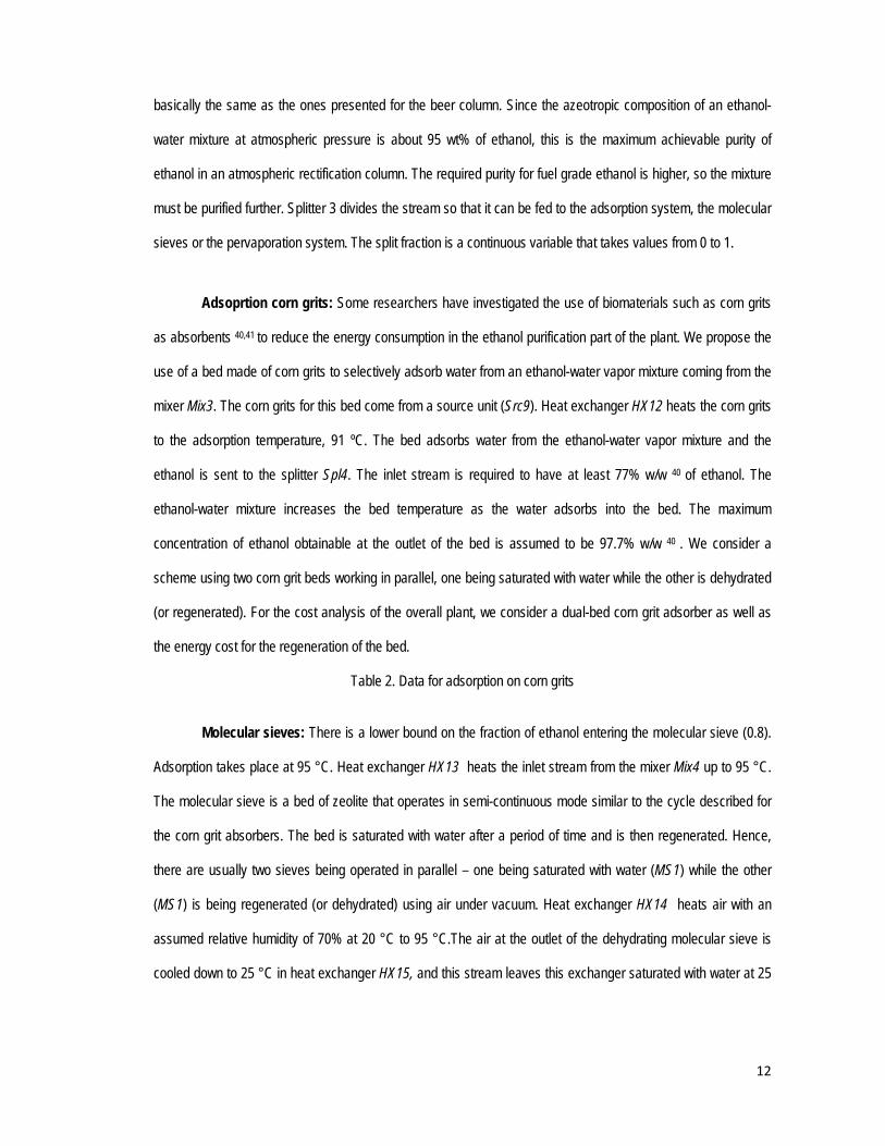
Ethanol dehydratation
Figure 8.- Ethanol dehydration superstructure.
Four different alternatives have been considered for the dehydration of ethanol, which can be used in
parallel or sequentially. Figure 8 shows the superestructure for the final dehydration of the ethanol. Only the
rectification and the adsorption in corn grits do not yield the final product because they cannot provide fuel quality,
but can be alternatives for reducing the energy consumption. Apart from these two options, molecular sieves and
pervaporation are also considered. Splitter 2 divides the stream into the four alternatives.
Distillation: The rectifier column is modeled in a similar fashion as the beer column. A partial
condenser and reboiler are used in this unit. The pressure drop in the column and the tray efficiencies are
assumed to be the same as those for the beer column. Again, the ethanol recovery is fixed at 99.6% and the
recovery of water at the top of the column is selected to be a variable. The composition of the condensate in the
condenser of this column is calculated assuming equilibrium between the vapor outlet and the liquid reflux
stream. The condenser temperature is determined from the dew point equation for the top outlet composition.
Furthermore, it is assumed that only water is vaporized in the reboiler and the temperature of the reboiler is
calculated using the bubble point equation for the bottom outlet composition. A reflux ratio of 5 is selected so that
the column design is feasible. The equations for determining the temperatures of the bottom and distillate are
12
basically the same as the ones presented for the beer column. Since the azeotropic composition of an ethanol-
water mixture at atmospheric pressure is about 95 wt% of ethanol, this is the maximum achievable purity of
ethanol in an atmospheric rectification column. The required purity for fuel grade ethanol is higher, so the mixture
must be purified further. Splitter 3 divides the stream so that it can be fed to the adsorption system, the molecular
sieves or the pervaporation system. The split fraction is a continuous variable that takes values from 0 to 1.
Adsoprtion corn grits: Some researchers have investigated the use of biomaterials such as corn grits
as absorbents 40,41 to reduce the energy consumption in the ethanol purification part of the plant. We propose the
use of a bed made of corn grits to selectively adsorb water from an ethanol-water vapor mixture coming from the
mixer Mix3. The corn grits for this bed come from a source unit (Src9). Heat exchanger HX12 heats the corn grits
to the adsorption temperature, 91 ºC. The bed adsorbs water from the ethanol-water vapor mixture and the
ethanol is sent to the splitter Spl4. The inlet stream is required to have at least 77% w/w 40 of ethanol. The
ethanol-water mixture increases the bed temperature as the water adsorbs into the bed. The maximum
concentration of ethanol obtainable at the outlet of the bed is assumed to be 97.7% w/w 40 . We consider a
scheme using two corn grit beds working in parallel, one being saturated with water while the other is dehydrated
(or regenerated). For the cost analysis of the overall plant, we consider a dual-bed corn grit adsorber as well as
the energy cost for the regeneration of the bed.
Table 2. Data for adsorption on corn grits
Molecular sieves: There is a lower bound on the fraction of ethanol entering the molecular sieve (0.8).
Adsorption takes place at 95 °C. Heat exchanger HX13 heats the inlet stream from the mixer Mix4 up to 95 °C.
The molecular sieve is a bed of zeolite that operates in semi-continuous mode similar to the cycle described for
the corn grit absorbers. The bed is saturated with water after a period of time and is then regenerated. Hence,
there are usually two sieves being operated in parallel – one being saturated with water (MS1) while the other
(MS1) is being regenerated (or dehydrated) using air under vacuum. Heat exchanger HX14 heats air with an
assumed relative humidity of 70% at 20 °C to 95 °C.The air at the outlet of the dehydrating molecular sieve is
cooled down to 25 °C in heat exchanger HX15, and this stream leaves this exchanger saturated with water at 25
13
°C. The data used in the model for the molecular sieves is taken from Jacques et al. (1999)57 and is summarized
in Table 3.
Table 3. Data for molecular sieves
Pervaporation: Membranes can also discriminate between components because of an interaction
between one of the separating components and the membrane taking place during diffusion, such as seen with
ion-exchange and hydrophilic membranes. Pervaporation separates a component from a liquid mixture based on
the permeability of the membranes to one of the components. A three pervaporation system is considered to
achieve fuel quality. It can receive flows from the rectification column, the corn grit adsorption unit, or the
molecular sieves. The mixing of these streams (Mix5) is assumed to be adiabatic. Each effect operates at 90 ºC.
Thus, HX 16 is used to adjust the inlet temperature. The maximum water composition at the inlet is 15%. The
water recoveries are 0.95, 0.97 and 1 in each of the effects respectively 43. In each of the stages the energy to
evaporate the water is obtained from cooling the liquid stream. Thus, reheating is needed between effects to heat
up the stream again up to 90ºC by means of HX17 and HX18 for the second and third effect, respectively.
Final product: The ethanol with fuel quality is condensed and / or just cooled down to 25ºC.
Solution procedure
To solve the superstructure, the MINLP is decomposed into two NLPs of about 2000 equations and 3000
variables each, one for diluted acid pretreatment and another one for AFEX. The superstructure for separation is
modeled with split fractions. The problem is optimized in terms of energy consumption in the flowsheet.
Once this optimization is completed, multi-effect columns 44,45 are used to replace the distillation column
by two or more columns. By operating the columns at different pressures, the condenser of a higher pressure
column serves as the reboiler of a lower pressure column. The inlet feed is split between all the columns, and
their top and bottoms products are mixed together to obtain the final products with the desired flow rates and
compositions. A schematic of a three effect distillation column, like the ones used in this work, is shown in Fig 9.
14
In this work we considered multieffect columns with up to three columns. For determining the fraction of
feed to be sent to each column and the operating pressures of the columns, we set up an optimization model to
minimize the total annualized cost for the multieffect columns
costwatercoolingannualcoststeamannualcostequipmentannualizedcost (5)
subject to the constraint that product composition at the top and bottom of each column must match the ones
obtained for a single distillation column from the results of the previous optimization. Hence, additional heat
exchangers as well as compressors may be required to meet the initial conditions, whose investment cost and
utility cost would be included in the total cost objective. Also, isenthalpic expansion valves may be needed for
some streams so as to match the pressure of the low pressure columns.
Figure 9.- Superstructure for the multieffect columns
Finally, heat integration 39,46 is performed to further reduce the energy consumption. Due to the fact that
the flowsheet has no recycle and the conversions of the reactors as well as the operating conditions are fixed, the
need to perform simultaneous structural optimization and heat integration is not as critical. Heat integration
among the hot and cold streams across the whole plant yields considerable savings in the utilities (steam, cooling
water) and consequently in the operating costs 39,46 . To carry out the heat integration, the software SYNHEAT
(http://newton.cheme.cmu.edu/interfaces) is used. The software is based on the work by Yee and Grossmann
(1990)47 , and uses an MINLP model to determine a minimum cost network, where the heat exchanger areas and
the stream matches are optimized simultaneously given the heat loads in different streams and the inlet and
outlet temperatures of these streams.
In the case of the dilute acid pretreatment, the vapor recovered from the process is used in HX21, see
Fig. 1 & Fig. 4, to provide energy for the process in the heat exchanger network (HEN). Once no more energy can
be recovered, the water is fed to tank 1, which reduces the vapor needed in the pretreatment as well as the
water. In order to determine the temperature of tank 1, several iterations are carried out as follows:
(1) Energy optimization of the flowsheet.
(2) Developement of HEN using Synheat and implementation of multieffect column.
(3) Readjust the conditions in tank 1 and reoptimize. Go to 1.
Repeat until the flows do not change.

15
Results
The production capacity of Bioethanol plants from lignocellulosic biomass is limited by the availability of
biomass in the region. Current trends as well as NREL reports suggest values in the range of 40 to 60 Mgal / yr.
Thus, in order to compare with results in the literature 8, 38, 48 the production capacity of the plant is fixed at 60
Mgal/yr.
Based on the energy optimization of the process flowsheet, the energy consumption for the dilute acid
pretreatment is 87MW versus 105MW for the AFEX. The optimal flowsheet is shown in Figure 10. It uses the
dilute acid as pretreatment and in order to dehydrate the ethanol a combination of beer column and molecular
sieves is suggested by the optimization. Even though we could stop the analysis of the AFEX pretreatment at this
point, it is useful to show the results for energy integration and the production cost of both pretreatments so as to
obtain more detailed information of both alternatives.
We first substitute the beer column by multieffect columns to reduce the energy and cooling water use.
A three effect multieffect column is the best option. Next, we perform heat integration using SYNHEAT to obtain
the optimal heat exchanger network. As an example, Figure 11 shows the T-Q curve for the dilute acid
pretreatment. In the T-Q curve, the multieffect columns are included but neither the energy demand of the
reactors nor the steam injected for the pretreatment are included. As it can be seen if Fig. 11, a fair amount of
energy can be integrated, which helps in the economy of the process.
Figure 10.- Optimized flowsheet.
Figure 11.- T- Q curve for the production of ethanol using dilute acid pretreatment.
Discussion.
Heat integration is performed using SYNHEAT to design the optimal heat exchanger network. Figure 12
shows the energy consumption (orange) and cooling requirements (blue) after heat integration. The production of
ethanol from lignocellulosic using dilute acid pretreatment requires more energy but only half the cooling of AFEX.
Figure 12.- Enegy balance for the production of ethanol from switchgrass and corn
16
In figure 12 we see that the thermal energy consumption for the production of ethanol from switchgrass
via hydrolysis is almost twice the one requried for the corn based process as well as the cooling needs. On this
grounds the process is not attractive compared to the corn based ethanol, since the only advantage is tha the raw
material does not interfere with the food chain. However, there is another source of energy in the process. The
energy obtained from the lignin is not included in the orange columns of Figure 12. Lignin is a very interesting
coproduct to produce energy. It is reported that lignin can produce 26100 kJ/kg, a value close to the enegy
obtained by burning coal 49 . In typical power plants, its maximum efficiency is about 75-80%50 . Thus, a boiler is
considered to generate the steam from lignin and its cost is included in the equipment cost. In red we show the
contribution of the energy generated by burning the ligning to the energy consumed/produced in the process. In
this case, both processes are energetically more favorable than using corn as raw material (the electrical energy
in the grinding is not included so as to compare with the results presented in the corn based process38). In Figure
12 the cooling water requirements are also shown. Both cases require higher consumptions of cooling water than
the case of the corn ethanol. In the case of the dilute acid, this difference is smaller.
Economic evaluation.
The energy analysis of the process reveals a trade-off between both processes since AFEX generates
more energy but also requires more cooling that dilute acid. Furthermore, according to the literature18 the yield of
AFEX is lower due to the high fraction of lignin in the switchgrass. Figure 13 shows the comparison of the raw
material consumption for the two alternatives compared with corn based ethanol. The consumption of
lignocellulosic biomass is higher than that of corn grains for the same production of ethanol. Thus, the solution to
the tradeoffs relies on a detailed economic evaluation of both alternatives.
Figure 13.- Consumption of raw material for the production of 60Mgal /yr
The costs for utilities and raw material are updated from the literature (0.019 $/kg Steam, 0.057 $/ton
cooling water 51. Electricity: 0.06 $/kWh 52, Switchgrass price: 30 $/TM 53,54). The generation of an excess of
steam is considered as a revenue of 0.0077$/kgsteam (updated from Smith and Varbanov, 200555) and the
equipment pricing which is obtained from (www.matche.com)56,8. Table 4 summarizes the results of the economic
17
evaluation. Dilute acid and AFEX pretreatment show similar results, but the lower yield of the AFEX pretreatment
together with its higher demand of cooling water shown in Figure 12, makes this pretreatment alternative less
attractive.
Table 4.- Production cost of ethanol via hydrolysis of lignocellulosic raw material
Fig. 14 shows the distribution of manufacturing cost for the optimal process that is based on dilute acid
pretreatment (Fig. 10). The contribution of the raw material is in the range reported by the literature, around
40%,13 followed by the annualized equipment cost and miscellaneous, including chemicals, maintenance and
administration, for a total of $48.5 MM/yr.
Figure 14. Cost distribution for the diluted acid pretreatment
Table 5.- Summary of economic data of the optimal design
If we compare the final production costs for second generation ethanol in Table 4 with different values
available in the literature, the results are promising. We acknowledge that the comparison is not totally consistent
because of different assumptions of the various sources. However, the results should still provide a useful
indicator. In terms of production cost for biochemical production of ethanol from lignocellulosic raw materials, for
the acid/enzymatic hydrolysis process the target by NREL is $1.33 /gal from corn stover,13 while others are more
optimistic aiming at values lower that $1.10 per gallon ethanol 57. However, a recent study by Kazi et al. (2010)14
reports a production cost much higher than the ones in the literature based on the different price for the feedstock
or the assumptions in the model (e. g. conversions, yield). The estimate of the current commercial scale for
lignocellulosic materials is at $2.43 /gal13 . This work reports values in the range of $0.8 /gal for ethanol produced
from switchgrass.
We can also compare with production costs of thermo-chemical path. It turns out that Phillips et al.
(2007)48 reported a price for ethanol of $1.22 /gallon (with a reduction of 20.7/100 $/gallon of byproduct credits)
via indirect gasification and high alcohols synthetic path, while Dutta and Phillips (2009)58 reported a price of 1.95
$/gal for direct gasification and high alcohols synthesis. For the production of ethanol via gasification –
fermentation Huhnke (2008)59 reported a target price of $1.2 /gal. In both cases, these values can be improved.
In fact the Coskata process, based also on the fermentation of syngas, is claiming production costs under 1
18
$/gallon60. Martín & Grossmann (2010)8 showed that for the gasification based process the optimal flowsheet
involves a thermochemical path, with a yield to ethanol is 20% (kgethanol/kgbiomass) generating 18MW of energy and
requiring 68MW of cooling. When selling the surplus of hydrogen, the manufacturing cost turns out to be $0.41
/gal ($63.9 millions/yr) and the investement cost is $335 millions.
Even though the manufacturing costs via hydrolysis are larger compared to the gasification based
process, the main advantage of the biochemical processes versus the thermo-chemical or thermo-biochemical
ones is the simpler process. As a result, the total investment cost61 of the optimal design is $169 MM (the
equipment cost is $38.4 MM calculated using the supplementary material in previous papers8), around half the
one reported by Martín and Grossmann8 for the gasification based production of ethanol from switchgrass.
Finally, we mention some of the uncertainties in the process and its impact in the energy consumption
and its economics:
-In order to keep the production cost below 1 $/gal for the optimal process flowsheet based on dilute acid
pretreatment, the cost of the switchgrass must lie below 50 $/MT (wet). For a price of 100 $/MT (wet) the cost of
ethanol increases up to $1.57/gal.
-It is expected that further development in fermentation technology will allow ethanol concentrations in
the reactor of 12%36. If the concentration of ethanol in the reactor increases from 8% (the value used in the study)
to 12%, a decrease in the consumption of energy up to 10% could be reached based on the lower needs in the
dehydration step.
-The uncertainty in the operating conditions and the yield of the pretreatments 11-13,18,62,63 may change the
decision upon the best process. It is expected that further experimental results will allow higher yields for the
pretreatments consuming less energy, ammonia and freshwater. For instance, if the conversion of the AFEX
reaches 90% for both hemicellulose and cellulose (similar to the values considered for the dilute acid
pretreatment) the production cost drops to $0.81/gal generating 40MW of energy and requiring 60MW of cooling
with a yield of 0.276kgEthanol/kgbiomass reaching the same efficiency of the dilute acid based process.
-There is uncertainty in the use of a boiler for generating energy from the lignin. On the one hand this
was proposed as alternative to make use of the lignin and thus obtain energy that will change the net energy
balance. On the other hand, we need to invest on a boiler. If we decide not to burn the lignin, then we save

19
investment cost but we need to pay for the steam required in the plant, as a result the manufacturing cost
increases to $1.04/gal, 25% increase, while the investment decreases to $141MM, 16%.
Conclusions.
The ethanol production from lignocellulosic swichgrass via hydrolysis has been modeled and optimized.
Two different pretreatments, dilute acid and AFEX, and four different dehydration processes (rectification,
adsorption, molecular sieves and pervaporation) were considered.
The optimal process involves the use of dilute acid pretreatment and for the dehydration a beer column
followed by molecular sieves to obtain fuel grade ethanol. The use of lignin is key for the profitability of the
process in terms of energy consumption. By burning the lignin, the optimized process produces energy even
though the requirements for cooling water are a somewhat higher than in the case of ethanol produced from corn.
As a result, the production cost of ethanol is $0.8 /gal including the cost of the equipment for the generation of
steam from the combustion of lignin.
Acknowledgments
The authors acknowledge NSF Grant CBET0966524 and Dr. M. Martín also acknowledges the financial
support from the Ministry of Education and Science of Spain and Fulbright commission providing a MICINN – Fulbright Postdoctoral fellowship. References. 1. Cole, D. E. Issues facing the Auto Industry: Alternative Fuels, Technologies, and Policies ACP Meeting Eagle Crest Conference Center June 20, 2007 2. White house press release, 2007 3. Piccolo, C., Bezzo, F., A techno-economic comparison between two technologies for bioethanol production from lignocelluloses. Biomass Bioener. 2009; 33: 478 – 491 4. Kszos, LA Bioenergy from switchgrass: reducing production costs by improving yield and optimizing crop management, 2006. website:
http://www.ornl.gov/ webworks/cppr/y2001/pres/114121.pdf (Nov. 29, 2006).
5. SenterNovem Bioethanol in Europe Overview and comparison of production processes, 2006. Rapport 2GAVE0601www.senternovem.nl
20
6. Huang, J. Qiu, H. and Scott Rozelle, S. More pain ahead for China’s food prices, Far Eastern Economic Review. 2008; 171 (5): 8–13. 7. Ritch, E. GM testing cellulosic ethanol. http://www.coskata.com/media/ October 2009 8. Martín, M., Grossmann, I.E. Energy optimization of lignocellulosic bioethanol production via gasification. AIChE J. 2011, DOI: 10.1002/aic.12544 9. Hamelinck, C.N., Hooijdonk, G. v., Faaij, A.P.C Ethanol from lignocellulosic biomass: techno-economic performance in short-, middle- and long-term. Biomass Bioener. 2005; 28: 384-410 10. Cardona Alzate, C.A., Sánchez Toro, O.J. Energy consumption analysis of integrated flowsheets for production of fuel ethanol from lignocellulosic biomass. Energy. 2006; 31: 2447-2459 11. Zhang, S., Marechal, F., Gassner, M., Perin-Levasseur, Z., Qi, W., Ren, Z., Yan, Y., Favrat, D., Process Modeling and Integration of Fuel Ethanol Production from Lignocellulosic Biomass Based on Double Acid Hydrolysis. Energy Fuels. 2009; 23 (3): 1759–1765 12. Keshwani, D. R., Cheng, J.J. Switchgrass for bioethanol and other value-added applications: A review Bioresour. Technology. 2009; 100: 1515–1523 13. Aden, A., Foust, T. Technoeconomic analysis of the dilute sulfuric acid and enzymatic hydrolysis process for the conversion of corn stover to ethanol. Cellulose. 2009; 16: 535-545 14 Kazi, F.K., Fortman, J.A., Anex, R.P., Hsu, D.D., Aden, A., Dutta, A., Kothandaraman, G, Technoeconomic comparison of process technologies for biochemical ethanol production from corn stover. Fuel. 2010; 89: S20-S2 15. Daichendt, M.M., Grossmann, I.E. Integration of Hierarchical Decomposition and Mathematical Programming for the Synthesis of Process Flowsheets, Comp. Chem. Eng. 1998; 22: 147-175 16. Grossmann, I. E.; Caballero, J. A.; Yeomans, H. Mathematical Programming Approaches to the Synthesis of Chemical Process Systems”, Korean J. Chem. Eng. 1999; 16: 407-426. 17. Well, J., Westgate, P., Kohlmann, K., Ladish, M.R. Cellulose pretreatment of lignocellulosic substrates. Enzyme. Microb Technol. 1994; 16: 1002-1004. 18. Sun, Y., Cheng, J., Hydrolysis of lignocellulosic materials for ethanol production: a review. Bioresour. Technol. 2002; 83: 1-11 19. Taherzadeh, M., Karimi, K., Pretreatment of Lignocellulosic Wastes to improve ethanol and biogas production: A review. Int. J. Mol. Sci. 2008; 9: 1621-1651 20. Eggeman, T., Elander, R.T. Process and economic analysis of pretreatment technologies. Bioresour.Technol. 2005; 96: 2019-2025 21. Mosier N., Wyman, C., Dale, B., Elander, R., Lee, Y.Y., Holtapple, M., Ladish, M. Features of promising technologies for pretreatment of lignocellulosic biomass. Bioresour. Technol. 2005; 96: 673-686 22. Kumar, P., Barrett, D.M., Delwiche, M.J. Stroeve, P. Methods for pretreatment of lignocellulosic biomass for efficient hydrolysis and biofuel production. Ind. Eng. Chem. Res. 2009; 48: 3713–3729. 23. Sierra, R., Smith, A., Granda, C., Holtzapple, M.T. Producing Fuel san Chemicals from lignocellulosic Biomass. CEP. 2008, August: S10-S18 24. Chisti, Y. Biodiesel from microalgae. Biotechnol. Adv. 2007; 25: 294-306.
21
25. United Nations Food and Agriculture Organization. The State of Food and Agriculture. 2008 26. Oak Ridge National Laboratory. Biofuels from Switchgrass: Greener Energy Pastures.”2005
27. Fulton, L. Biodiesel: technology perspectives. Geneva UNCTAD Conference. 2006 28. Schell, D.J., Farmer, J., Newman, M., McMillan, J.D. Dilute Sulfuric Acid Pretreatment of Corn Stover in Pilot – Scale reactor. Appl. Biochem. Biotech. 2003; 105-108: 69-85 29. Alizadeh, H., Teymouri, F., Gilbert, T.I. and Dale, B.E. Pretreatment of switchgrass by ammonia fiber explosion (AFEX) . Appl. Biochem. Biotech. 2005; 121-124: 1133-1141 30. Murnen, H.K., Balan, V., Chundawat, S.P.S., Bals., B., Sousa, L. da C., Dale, B.E. Optimization of Amonia fiber expansion (AFEX) pretreatment and enzymatic hydrolysis of Miscanthus x giganteus to Fermentable sugars. Biotechnol. Prog. 2007; 23: 846-850 31. Gregg, D., Saddler, J.N. Bioconversion of lignocellulosic residue to ethanol: Process flowsheet development. Biomass Bioener. 1995; 9 (1-5): 287-302 32. Wooley, R., Ruth, M., Sheehan, J., Ibsen, K., Majdeski, H., Galvez, A Lignocellulosic biomass to ethanol process design and economics utilizing co-current dilute acid prehydrolysis and enzymatic hydrolysis current and futuristic scenarios NREL/ TP – 580- 26157. 1999
33. Mani, S., Tabil, L.G., Sokhansanj, S. Grinding performance and physical properties of wheat and barley straws, corn stover and switchgrass. Biomass Bioenerg. 2004; 27: 339-352
34. Holtzapple, M.T., Jun, J-A., Ashok, G., Patibandla, S. L., Dale, B. E. The Ammonia Freeze Explosion (AFEX) Process A Practical Lignocellulose Pretreatment . Appl. Biochem. Biotech. 1992; 28/29: 59-74 35. National Lime Association Using lime for acid neutralization. A proven solution! http://www.lime.org. Last accesed June 2010. 36. Dimian, A.C., Sorin, C. Chemical Process Design. Computer – Aided Case Studies. Weinheim: Wiley-VCH., 2008 37. Wooley, R.J., Putsche, V. Development of an ASPEN PLUS Physical Property Database for Biofuels Components NREL/MP-425-20685. 1996. http://www.p2pays.org/ref/22/21210.pdf 38. Karuppiah, R., Peschel, A., Grossmann, I.E., Martín, M., Martinson, W., Zullo, L. Energy optimization of an Ethanol Plant. AICHE J. 2008; 54: 1499-1525 39. Biegler, L.T., Grossmann, I. E., Westerberg, A. W. Systematic Methods of Chemical Process Design. New Jersey: Prentice Hall, 1997 40. Ladisch, M.R. Dyck, K. Dehydration of Ethanol: New Approach Gives Positive Energy Balance. Science. 1979; 205 (4409): 898 – 900 41. Beery, K. E., Ladisch, M. R. Adsorption of Water from Liquid-Phase Ethanol-Water Mixtures at Room Temperature using Starch-Based Adsorbents, Ind. Eng. Chem. Res. 2001; 40: 2112-2115 42. Jacques, K., Lyons, T. P., Kelsall, D. R. The Alcohol Textbook, 3rd ed., Nottingham University Press., United Kingdom, 1999.

22
43. Braisher, M., Gill, S., Treharne, W., Wallace, M., Winterburn, J., Cui, Z., Das, D.B., Snowdon, C.Design Proposal. Bioethanol Production Plant. Project Report. May 2006 44. Larsson, M., Zacchi, G. Production of ethanol from dilute glucose solutions. A technical –economic evaluation of various refining alternatives. Bioprocess. Eng. 1996; 15: 125-132 45. Haelssig, J.B., Tremblay, Thibault, J.Technical and economic considerations for various recovery schemes in ethanol production by fermentation. Ind. Eng. Chem. Res. 2008; 47: 6185-6191 46. Linhoff, B., Townsend, D. W., Boland, D.; Hewitt, G. F., Thomas, B. E. A., Guy, A. R., Marsland, R. H.User Guide on Process Integration for the Efficient Use of Energy, IChemE, Rugby, England, 1982 47. Yee, T.F., Grossmann, I.E. Simultaneous optimization models for heat integration – II. Heat exchanger networks synthesis. Comp. Chem. Eng. 1990; 28: 1165-1184. 48. Phillips, S., Aden, A., Jechura, J. and Dayton, D., Eggeman, T. Thermochemical Ethanol via Indirect Gasification and Mixed Alcohol Synthesis of Lignocellulosic Biomass Technical Report, NREL/TP-510-41168, April 2007
49. McLaughlin, S. B., Samson, R., Bransby, D., Wiselogel, A. Evaluating physical, chemical and energetic properties of perennial grasses as biofuels. Proc., BIOENERGY '96 - The Seventh National Bioenergy Conference: Partnerships to Develop and Apply Biomass Technologies, September 15-20, 1996, Nashville, Tennessee.
50. Martin, J.R. Biomass Energy Economics Western Forest Economists 43rd Annual Meeting May, 7, 2008 http://www.masonbruce.com/wfe/2008Program/martin.pdf accessed Nov, 2009.
51. Franceschin, G., Zamboni, A., Bezzo, F., Bertucco, A. Ethanol from corn: a technical and economical assessment based on different scenarios Chem. Eng. Res. Des. 2008; 86 (5): 488-498 52. Balat, M., Balat, H., Öz, C. (2008) Progress in bioethanol processing. Prog. Energ. Combust. 2008; 34 (5): 551-573 53. Lave, L.B., Griffin W.M. The Green Bullet Foreing policy Posted March 2006 54. Personal communication Dow Chemical 55. Smith, R., Varbanov, P. What’s the price of Steam? CEP. 2005; July: 29-33 56. www.matche.com 57. Ibsen, K. N. Technology Advances in Biobased Fuels Am. Chem. Soc., Div. Fuel Chem. 2004; 49(2): 740-741 58. Dutta, A., Phillips, S.D. Thermochemical Ethanol via Direct Gasification and Mixed alcohol Synthesis of Lignocellulosic Biomass. NREL/ TP-510-45913. 2009 59. Huhnke, R. L. (2008) Cellulosic ethanol using gasification-fermentation. Resource: Engineering & Technology for a Sustainable World http://findarticles.com/p/articles/mi_hb4979/is_2_15/ai_n29430181/ (Last accessed Sep 2010) 60. Synbio 2009 http://www.synbio.org.uk/component/content/article/99-biotechnology-news/551-gm-and-coskata-claim-cellulosic-ethanol-has-arrived-gasification-fermentation-process-yields-biofuel-for-under-1-per-gallon.html?directory=260 accessed Nov 17 2009,

23
61. Sinnot, R.K., Coulson and Richardson, Chemical Engineering 3ªEd. Singapur: Butterworth Heinemann, 1999 62. Sendich, E.N, Lase, M., Kim, S., Alizadeh, H., Laureano-Perez, L., Dale, B., Lynd, L. Recent process improvements for the ammonia fiber expansion (AFEX) process and resulting reductions in minimum ethanol selling price. Bioresour Technol. 2008; 99: 8429–8435 63. Laser, M., Jin, H., Jayawardhana, K., Lynd, L.R. Coproduction of ethanol and power from switchgrass. Biofuels Bioproducts and Biorefining Biofuels, Bioprod. Bioref.2009; 3:195–218 64. Personal communication with Cargill
24
Figure Captions
Figure 1.- Superstructure of the ligno - ethanol production plant via hydrolysis
Figure 2.- Lignocellulosic structure
Figure 3.-Flowsheet for AFEX pretreatment
Figure 4.- Dilute acid pretreatment.
Figure 5.- Flowsheet for hydrolysis
Figure 6.-Detail of flowsheet for fementor.
Figure 7.- Detail for the Beer column
Figure 8.- Ethanol dehydration superstructure.
Figure 9.- Superstructure for the multieffect columns. a: fraction of total feed to LP column b: fraction of total
feed to IP column
Figure 10.- Optimized flowsheet.
Figure 11.- T- Q curve for the production of ethanol using dilute acid pretreatment.
Figure 12.- Enegy balance for the production of ethanol from switchgrass and corn. Orange: Energy consumed
after superstrucure optimization with heat integration. Red: Energy consumed after the contribution of lignin
Blue: Cooling water requirements after heat integration
Figure 13.- Consumption of raw material for the production of 60Mgal /yr
Figure 14. Cost distribution for the diluted acid pretreatment
Related Documents


