Zhang et al. Energy Mater 2021; Volume:Number DOI: 10.20517/energymater.2021.xx © The Author(s) 2021. Open Access This article is licensed under a Creative Commons Attribution 4.0 International License (https://creativecommons.org/licenses/by/4.0/), which permits unrestricted use, sharing, adaptation, distribution and reproduction in any medium or format, for any purpose, even commercially, as long as you give appropriate credit to the original author(s) and the source, provide a link to the Creative Commons license, and indicate if changes were made. www.energymaterj.com Energy Materials 1 Note: This version is accepted and the final version will be published shortly. 2 3 Article 4 5 Enhancing cycle life of nickel-rich LiNi 0.9 Co 0.05 Mn 0.05 O 2 via a highly 6 fluorinated electrolyte additive - pentafluoropyridine 7 8 Xiaozhen Zhang, Gaopan Liu, Ke Zhou, Tianpeng Jiao, Yue Zou, Qilong Wu, 9 Xunxin Chen, Yong Yang, Jianming Zheng* 10 11 State Key Laboratory of Physical Chemistry of Solid Surfaces, College of Chemistry 12 and Chemical Engineering, Xiamen University, Xiamen 361005, China. 13 14 *Correspondence to: Prof. Jianming Zheng, State Key Laboratory of Physical 15 Chemistry of Solid Surfaces, College of Chemistry and Chemical Engineering, Xiamen 16 University, Xiamen 361005, China. E-mail: [email protected] 17 18 How to cite this article: Zhang X, Liu G, Zhou K, Jiao T, Zou Y,Wu Q, Chen X, Yang 19 Y, Zheng J. Enhancing cycle life of nickel-rich LiNi 0.9 Co 0.05 Mn 0.05 O 2 via a 20 highly fluorinated electrolyte additive - pentafluoropyridine. Energy 21 Mater 2021;1:[Accept]. https://dx.doi.org/10.20517/energymater.2021.07 22 23 Received: 7 Sep 2021 Revised: 1 Oct 2021 Accepted: 8 Oct 2021 First online: 8 Oct 24 2021 25 26 27 28 29

Welcome message from author
This document is posted to help you gain knowledge. Please leave a comment to let me know what you think about it! Share it to your friends and learn new things together.
Transcript
Zhang et al. Energy Mater 2021; Volume:NumberDOI: 10.20517/energymater.2021.xx
© The Author(s) 2021. Open Access This article is licensed under a Creative Commons Attribution 4.0 International License
(https://creativecommons.org/licenses/by/4.0/), which permits unrestricted use, sharing, adaptation, distribution and reproduction in any medium or
format, for any purpose, even commercially, as long as you give appropriate credit to the original author(s) and the source, provide a link to the Creative Commons license, and
indicate if changes were made.
www.energymaterj.com
Energy Materials1
Note: This version is accepted and the final version will be published shortly.2
3
Article4
5
Enhancing cycle life of nickel-rich LiNi0.9Co0.05Mn0.05O2 via a highly6
fluorinated electrolyte additive - pentafluoropyridine7
8
Xiaozhen Zhang, Gaopan Liu, Ke Zhou, Tianpeng Jiao, Yue Zou, Qilong Wu,9
Xunxin Chen, Yong Yang, Jianming Zheng*10
11
State Key Laboratory of Physical Chemistry of Solid Surfaces, College of Chemistry12
and Chemical Engineering, Xiamen University, Xiamen 361005, China.13
14
*Correspondence to: Prof. Jianming Zheng, State Key Laboratory of Physical15
Chemistry of Solid Surfaces, College of Chemistry and Chemical Engineering, Xiamen16
University, Xiamen 361005, China. E-mail: [email protected]
18
How to cite this article: Zhang X, Liu G, Zhou K, Jiao T, Zou Y, Wu Q, Chen X, Yang19
Y, Zheng J. Enhancing cycle life of nickel-rich LiNi0.9Co0.05Mn0.05O2 via a20
highly fluorinated electrolyte additive - pentafluoropyridine. Energy21
Mater 2021;1:[Accept]. https://dx.doi.org/10.20517/energymater.2021.0722
23
Received: 7 Sep 2021 Revised: 1 Oct 2021 Accepted: 8 Oct 2021 First online: 8 Oct24
202125
26
27
28
29
Page 1 of 23 Zhang et al. Energy Mater 2021; Volume:Number│http://dx.doi.org/10.20517/energymater.2021.xx
30
Abstract31
A highly fluorinated additive, pentafluoropyridine (PFP), has been investigated to32
enhance the interfacial stability of Ni-rich LiNi0.9Co0.05Mn0.05O2 (NCM90) cathode33
electrode at a cut-off voltage of 4.3 V vs. Li/Li+ at 30 oC. The capacity retention of34
NCM90||Li cell is obviously improved from 72.3% to 80.3% after 200 cycles at 1C (1C35
= 180 mA/g) when 0.2% PFP is introduced into the baseline electrolyte (1 mol/L LiPF636
in EC/DEC). The improvement in electrochemical performance could be attributed to37
the formation of a compact and uniform cathode electrolyte interphase (CEI) layer38
enriched with F-containing polypyridine moieties and LiF species on the NCM9039
particles, which prevents the side reactions between the electrode and electrolyte and40
hinders the corrosion of cathode causing by HF attacking. In addition, the formation of41
internal particle cracks is somewhat suppressed by the robust CEI, thus prohibiting the42
irreversible phase transformation, and better maintaining the superior lithium-ion43
diffusion kinetics.44
45
Keywords: Pentafluoropyridine, electrolyte additive, cathode electrolyte interphase,46
LiNi0.9Co0.05Mn0.05O2, lithium-ion batteries47
48
49
INTRODUCTION50
Lithium-ion batteries (LIBs) have been widely investigated and deployed as the power51
sources of electric vehicles (EVs) owing to their relatively high energy density, long52
cycle life and environmentally friendliness.[1-4] However, up to now, the energy density53
of the LIBs is still not sufficient enough to achieve EV driving mileage that could54
compete the conventional cars driven by internal combustion engineers, thus impeding55
the complete substitution of EVs for conventional cars in the automobile market.56
Consequently, boosting the energy density of LIBs to relieve the “range anxiety”57
become an urgent demand to be met. Nickel-rich (Ni-rich) LiNixCoyMn1-x-yO2 (NCM, x58
≥ 0.9) layered oxides have been considered one of the most promising cathode materials59
Zhang et al. Energy Mater 2021; Volume:Number│http://dx.doi.org/10.20517/energymater.2021.xx Page 2 of 23
for next generation LIBs due to their high specific capacity and high achievable energy60
density, in comparison with LiCoO2 and NCM analogues with lower Ni content.[5-7]61
However, there are still some key problems unsolved for the Ni-rich cathode materials,62
especially the rapid capacity deterioration when operated with high charge cut-off63
voltages ≥ 4.3 V vs. Li/Li+. The reasons causing the rapid capacity deterioration of the64
Ni-rich NCM include (1) irreversible structure transformation from layered to65
disordered rock-salt phase during repeated charging and discharging process with66
excessive lithium utilization,[8] (2) the interfacial degradation resulted from the parasitic67
side reactions between Ni-rich NCM and electrolyte.[9, 10]68
69
Structural doping and surface modification are mostly adopted measures to improve the70
structural and interfacial stability of Ni-rich NCM.[11-14] Sim et al. coated the surface of71
LiNi0.9Co0.05Mn0.05O2 (NCM90) particles with 0.5 wt% tungsten oxide, realizing a72
capacity retention of 84.6% at 1C after 80 cycles, which surpassed the 76.6% for73
pristine NCM90.[15] Park et al.’s result showed that the 1 wt% boron doped NCM9074
could deliver a discharge capacity of 237 mAh g-1 at 4.3 V, with outstanding capacity75
retention of 91% after 100 cycles at 55 oC, which is 15% higher than the undoped76
counterpart.[16] Besides, manipulation of the material particle morphology and77
orientation, as well as the elemental distribution is also an alternative approach to78
overcome the degradation.[4] However, these strategies could not address all the issues79
existing with Ni-rich NCM, because the side reactions between active cathode materials80
and electrolyte could not be completely prevented.81
82
In this regard, incorporating functional additive into electrolyte is considered a feasible83
and scalable approach to ameliorate the electrochemical performance of the Ni-rich84
NCM electrode due to its cost effectiveness. It has been well established that the85
electrolyte with appropriate additive could generate a unique and protective cathode86
electrolyte interphase (CEI) film on the surface of cathode particles during initial87
formation process, thus improving the cycling performance of the cell.[9, 10, 17-19] Of note,88
research attention has been paid to N-containing heterocyclic molecules as functional89
Page 3 of 23 Zhang et al. Energy Mater 2021; Volume:Number│http://dx.doi.org/10.20517/energymater.2021.xx
electrolyte additives, due to its unique property and positive effect in CEI layer90
formation. For instance, Liao et al. utilized a 1-(2-cyanoethyl) pyrrole (CEP) to91
construct a protecting CEI film on LiNi0.8Co0.1Mn0.1O2, significantly boosting its cycling92
performance.[20] Besides, extensive research has conducted in exploiting pyridine93
derivatives, such as fluoropyridine family (2-fluoropyridine, 3-fluoropyridine, 4-94
fluoropyridine),[21] 2-vinylpyridine.[22] These additives are able to produce an effective95
and stable CEI on LiMn2O4 cathode and solid electrolyte interphase (SEI) on carbon96
anode, respectively. Particularly, LiF could be simultaneously formed from the break-97
down of fluoropyridine additive, generating LiF-containing robust CEI layer, which is98
beneficial to extend cycle life. However, these additives only contain one fluorine in the99
molecule structure, limiting the content of LiF in the CEI layer. Besides, to date, it is100
still unknown about the effect and functioning mechanism of the highly fluorinated101
pyridine for high energy density Ni-rich NCM.102
103
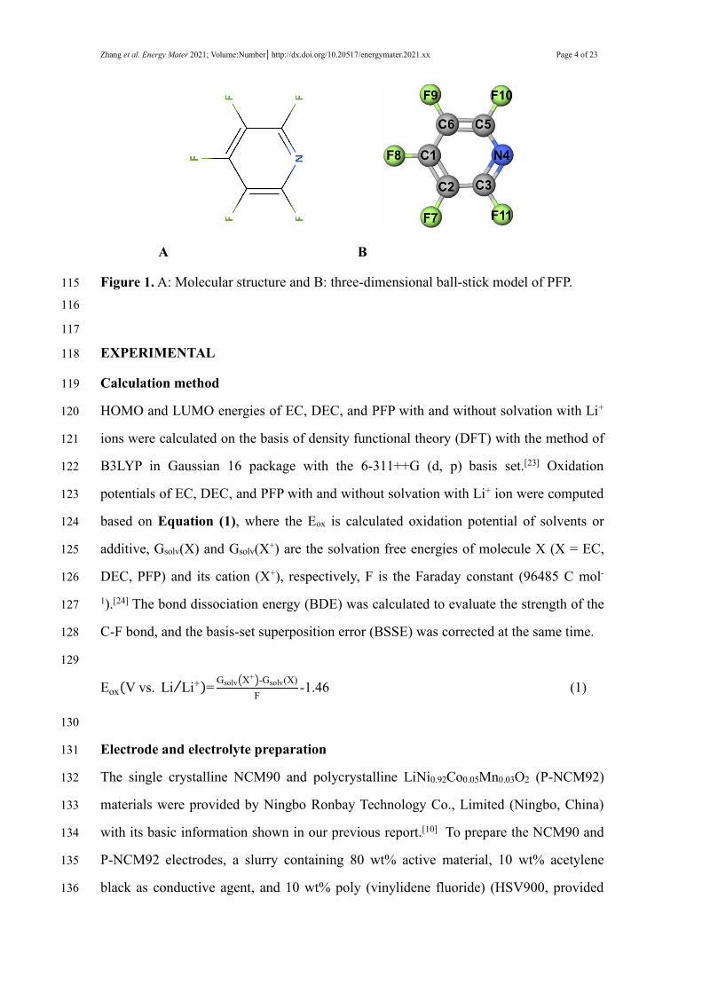
In this work, a highly fluorinated molecule, i.e., pentafluoropyridine (PFP, Figure 1)104
was explored for the first time as a functional electrolyte additive to enhance the105
electrochemical performance of Ni-rich NCM90 electrode. By introducing 0.2% PFP106
into the standard electrolyte (1 mol L-1 LiPF6 in EC/DEC), the capacity retention of107
NCM90 can reach 80.3% after 200 cycles at 1C, which is much higher than that of the108
standard electrolyte (72.3%). Electrochemical impedance spectroscopy (EIS),109
transmission electron microscope (TEM), scanning electron microscope (SEM), and X-110
ray photoelectron spectroscopy (XPS) were performed to explore the interfacial111
chemical environment and microstructural evolution of NCM90 electrode to obtain deep112
insight into the essential functioning mechanism for the PFP additive.113
114
Zhang et al. Energy Mater 2021; Volume:Number│http://dx.doi.org/10.20517/energymater.2021.xx Page 4 of 23
A B
Figure 1.A: Molecular structure and B: three-dimensional ball-stick model of PFP.115
116
117
EXPERIMENTAL118
Calculation method119
HOMO and LUMO energies of EC, DEC, and PFP with and without solvation with Li+120
ions were calculated on the basis of density functional theory (DFT) with the method of121
B3LYP in Gaussian 16 package with the 6-311++G (d, p) basis set.[23] Oxidation122
potentials of EC, DEC, and PFP with and without solvation with Li+ ion were computed123
based on Equation (1), where the Eox is calculated oxidation potential of solvents or124
additive, Gsolv(X) and Gsolv(X+) are the solvation free energies of molecule X (X = EC,125
DEC, PFP) and its cation (X+), respectively, F is the Faraday constant (96485 C mol-126
1).[24] The bond dissociation energy (BDE) was calculated to evaluate the strength of the127
C-F bond, and the basis-set superposition error (BSSE) was corrected at the same time.128
129
Eox V vs. Li Li+ = Gsolv X+ -Gsolv(X)F
-1.46 (1)
130
Electrode and electrolyte preparation131
The single crystalline NCM90 and polycrystalline LiNi0.92Co0.05Mn0.03O2 (P-NCM92)132
materials were provided by Ningbo Ronbay Technology Co., Limited (Ningbo, China)133
with its basic information shown in our previous report.[10] To prepare the NCM90 and134
P-NCM92 electrodes, a slurry containing 80 wt% active material, 10 wt% acetylene135
black as conductive agent, and 10 wt% poly (vinylidene fluoride) (HSV900, provided136

Page 5 of 23 Zhang et al. Energy Mater 2021; Volume:Number│http://dx.doi.org/10.20517/energymater.2021.xx
by Arkema) as a binder was coated onto the Al foil ( 16 um in thickness) and then dried137
at 110 oC in an air-convection oven. After that, the electrode was punched into certain138
circular disks of 1.54 cm-2 (14 mm in diameter) and baked in a 110 oC vacuum oven for139
1 hr, and then the as-prepared electrodes with loading of 2.5~3.0 mg cm-2 were140
transferred into an argon-filled glovebox (Shanghai Mikrouna Co., Ltd.) with141
moisture/oxygen contents controlled below 0.1 ppm. Lithium metal (15.8 mm in142
diameter, 2 mm in thickness, from China Energy Lithium Co., Ltd., Tianjin) was used as143
the negative electrode.144
145
The standard electrolyte (STD) was 1 mol L-1 LiPF6 dissolved in ethylene carbonate146
(EC) and diethyl carbonate (DEC) (3:7 by weight ratio), as provided by Zhangjiagang147
Guotai Huarong new material Co., Ltd. PFP, which was explored as a functional148
additive was purchased from Shanghai Bide Pharma Technology Co., Ltd. (Shanghai)149
and used without further purification. The optimized electrolytes were prepared by150
adding the PFP additive to the STD electrolyte with weight percentages of 0.2%, 0.5%151
and 1.0%, respectively.152
153
Electrochemical measurements154
CR2025 coin cells were fabricated with the as-prepared electrodes, Celgard2400 as the155
separator, Li metal as the negative electrode, along with 100 uL electrolyte in the above-156
mentioned argon-filled glovebox. For long-term cycling performance evaluation, the157
fabricated coin cells were rested for 5 hrs at 30 oC and then charged/discharged158
galvanostatically at 0.1C (1C = 180 mA g-1) for the initial 3 formation cycles and at 1C159
charge / 1C discharge for the subsequent cycles in the voltage range of 3.0~4.3 V at 30160
oC with Neware CT-4008 battery testers. Rate performance was assessed at ascending161
rates of 0.5C, 1C, 2C, 3C, 5C, 7C and 10C for 5 cycles, respectively, with the same162
charging rate of 0.2C after 3 formation cycles at 0.1C in the voltage range consistent163
with the long cycling performance test. EIS was performed on CHI760e (Chenhua,164
Shanghai) with a ±5 mV potential amplitude at the frequency between 100 kHz and165
Zhang et al. Energy Mater 2021; Volume:Number│http://dx.doi.org/10.20517/energymater.2021.xx Page 6 of 23
0.001 Hz. Linear sweep voltammetry (LSV) was also recorded on CHI760e at a166
scanning rate 0.1 mV s-1 from open circuit potential to 7.0 V vs. Li/Li+ at room167
temperature utilizing a graphite working electrode and a lithium metal as counter and168
reference electrode.169
170
Characterizations171
For post-mortem analysis, cycled NCM90 electrodes were obtained from the172
disassembled cells, then washed by dimethyl carbonate (DMC) for 3 times to eliminate173
the residual electrolyte. The morphology of NCM90 electrodes were characterized by174
SEM (S-4800, HITACHI). The characterization of CEI layer formation on NCM90175
particle surface was carried out by TEM (Tecnai F30 TWIN, FEI). The difference in176
chemical components on the surface of NCM90 electrode was explored by XPS (PHI-177
5000, ULVAC-PHI) using Al K X-ray (1486.7 eV) source for excitation, with the178
binding energy referring to residual Carbon (C-C) at 284.8 eV.179
180
RESULTSAND DISCUSSION181
Oxidative Stability of PFP182
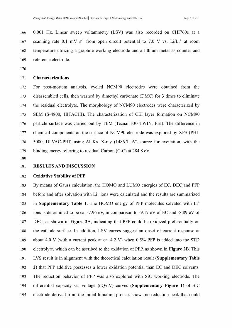
By means of Gauss calculation, the HOMO and LUMO energies of EC, DEC and PFP183
before and after solvation with Li+ ions were calculated and the results are summarized184
in Supplementary Table 1. The HOMO energy of PFP molecules solvated with Li+185
ions is determined to be ca. -7.96 eV, in comparison to -9.17 eV of EC and -8.89 eV of186
DEC, as shown in Figure 2A, indicating that PFP could be oxidized preferentially on187
the cathode surface. In addition, LSV curves suggest an onset of current response at188
about 4.0 V (with a current peak at ca. 4.2 V) when 0.5% PFP is added into the STD189
electrolyte, which can be ascribed to the oxidation of PFP, as shown in Figure 2B. This190
LVS result is in alignment with the theoretical calculation result (Supplementary Table191
2) that PFP additive possesses a lower oxidation potential than EC and DEC solvents.192
The reduction behavior of PFP was also explored with SiC working electrode. The193
differential capacity vs. voltage (dQ/dV) curves (Supplementary Figure 1) of SiC194
electrode derived from the initial lithiation process shows no reduction peak that could195
Page 7 of 23 Zhang et al. Energy Mater 2021; Volume:Number│http://dx.doi.org/10.20517/energymater.2021.xx
be assigned to PFP, which is consistent with the theoretical calculation result.196
197
A B
198
Figure 2. A: Calculated HOMO/LUMO energies (eV) of EC, DEC, and PFP solvated199
with Li+ ions; B: LSV curves of STD and 0.5% PFP-containing electrolytes measured200
with a graphite working electrode and Li metal as counter electrode at the scanning rate201
of 0.1 mV s-1.202
203
Electrochemical performance of NCM90 and P-NCM92 electrodes in Li half cells204
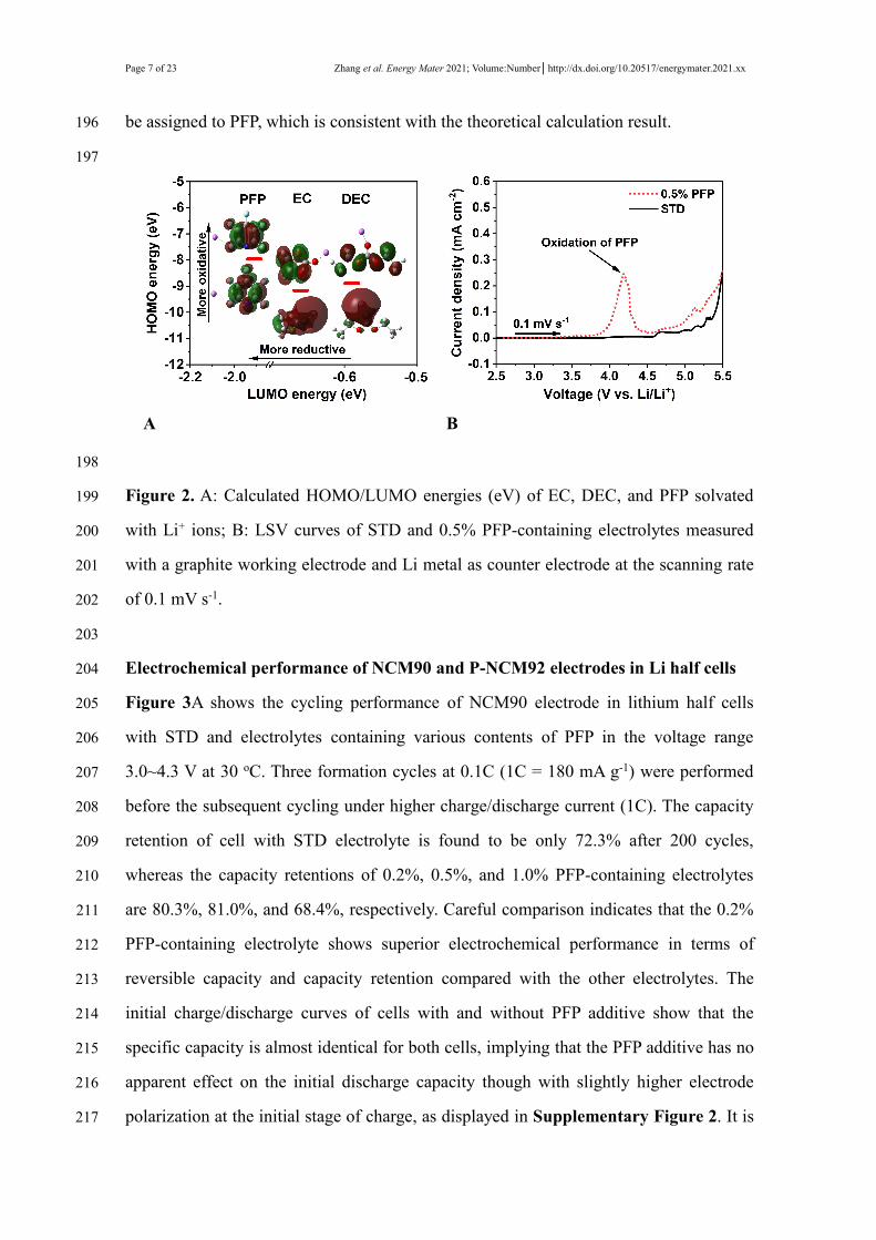
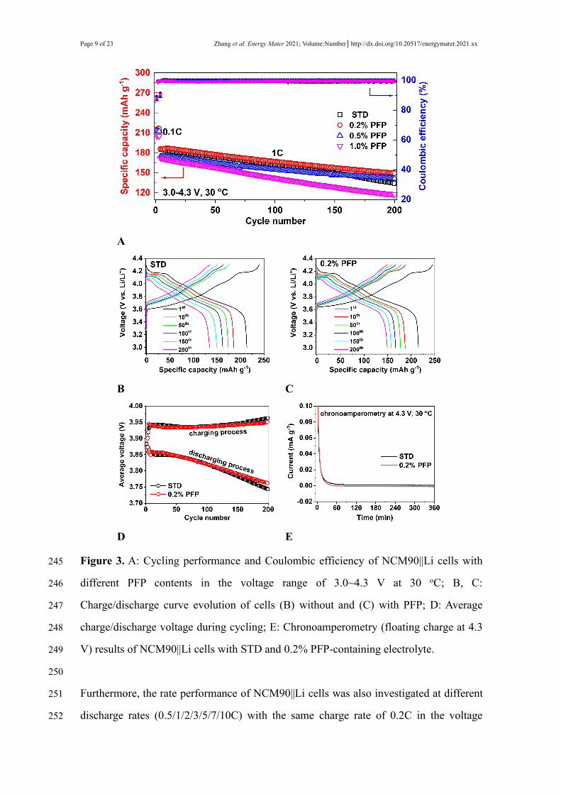
Figure 3A shows the cycling performance of NCM90 electrode in lithium half cells205
with STD and electrolytes containing various contents of PFP in the voltage range206
3.0~4.3 V at 30 oC. Three formation cycles at 0.1C (1C = 180 mA g-1) were performed207
before the subsequent cycling under higher charge/discharge current (1C). The capacity208
retention of cell with STD electrolyte is found to be only 72.3% after 200 cycles,209
whereas the capacity retentions of 0.2%, 0.5%, and 1.0% PFP-containing electrolytes210
are 80.3%, 81.0%, and 68.4%, respectively. Careful comparison indicates that the 0.2%211
PFP-containing electrolyte shows superior electrochemical performance in terms of212
reversible capacity and capacity retention compared with the other electrolytes. The213
initial charge/discharge curves of cells with and without PFP additive show that the214
specific capacity is almost identical for both cells, implying that the PFP additive has no215
apparent effect on the initial discharge capacity though with slightly higher electrode216
polarization at the initial stage of charge, as displayed in Supplementary Figure 2. It is217
Zhang et al. Energy Mater 2021; Volume:Number│http://dx.doi.org/10.20517/energymater.2021.xx Page 8 of 23
implied that the CEI layer formed on the NCM90 surface may be too thick in the218
presence of excessive PFP additive such as 0.5% or higher, which restricts the219
movement of Li+ ions through electrode-electrolyte interface, causing apparent decrease220
in specific capacity at 1C. Besides, the average Coulombic efficiency of cell with 0.2%221
PFP-containing electrolyte is 99.6% among 200 cycles, which is higher than the one222
with PFP-free electrolyte (99.0%), as shown in Supplementary Figure 3. The positive223
influence of PFP is further affirmed by the superior cycling stability when the NCM90224
electrodes were cycled at higher cut-off voltages of 4.4 V and 4.5 V (Supplementary225
Figures 4 and 5), and when higher active mass loading NCM90 electrodes were226
evaluated (Supplementary Figure 6), respectively.227
228
In addition, compared with PFP-containing electrolyte, the obvious polarization229
increase of charge/discharge plateaus of cell with STD electrolyte during prolonged230
cycling suggests that the degradation of electrode/electrolyte interface has a significant231
effect on cycling performance, as displayed in Figure 3B and C. It is believed the232
decomposition of electrolyte caused by the unwanted parasitic reactions on the NCM90233
particle surface contributing to this degradation during cycling. This phenomenon could234
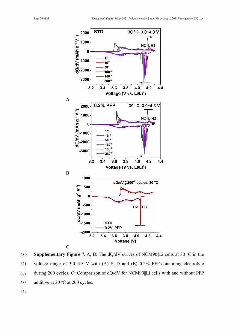
be further affirmed by the dQ/dV curves (Supplementary Figure 7) during repeated235
charge and discharge process, indicating that the cell with PFP additive exhibits slower236
shrinkage of redox peaks ca. 4.0~4.2 V, related to the H2~H3 phase transformation.[25]237
Higher average discharge voltage and lower average charge voltage during cycling238
process ascertains the stabilized electrode redox reaction process for cell with 0.2%239
PFP-containing electrolyte, as shown in Figure 3D. In addition, chronoamperometry240
test (i.e., floating charge at 4.3 V) result further evidences the stabilized interfacial CEI241
as generated with PFP additive, as reflected by the lower leakage current compared with242
the one without PFP additive, as shown in Figure 3E.243
244
Page 9 of 23 Zhang et al. Energy Mater 2021; Volume:Number│http://dx.doi.org/10.20517/energymater.2021.xx
A
B C
D E
Figure 3. A: Cycling performance and Coulombic efficiency of NCM90||Li cells with245
different PFP contents in the voltage range of 3.0~4.3 V at 30 oC; B, C:246
Charge/discharge curve evolution of cells (B) without and (C) with PFP; D: Average247
charge/discharge voltage during cycling; E: Chronoamperometry (floating charge at 4.3248
V) results of NCM90||Li cells with STD and 0.2% PFP-containing electrolyte.249
250
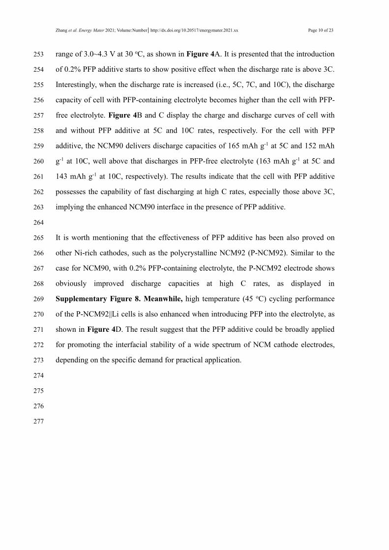
Furthermore, the rate performance of NCM90||Li cells was also investigated at different251
discharge rates (0.5/1/2/3/5/7/10C) with the same charge rate of 0.2C in the voltage252
Zhang et al. Energy Mater 2021; Volume:Number│http://dx.doi.org/10.20517/energymater.2021.xx Page 10 of 23
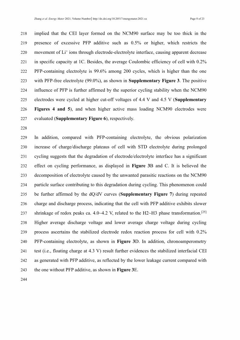
range of 3.0~4.3 V at 30 oC, as shown in Figure 4A. It is presented that the introduction253
of 0.2% PFP additive starts to show positive effect when the discharge rate is above 3C.254
Interestingly, when the discharge rate is increased (i.e., 5C, 7C, and 10C), the discharge255
capacity of cell with PFP-containing electrolyte becomes higher than the cell with PFP-256
free electrolyte. Figure 4B and C display the charge and discharge curves of cell with257
and without PFP additive at 5C and 10C rates, respectively. For the cell with PFP258
additive, the NCM90 delivers discharge capacities of 165 mAh g-1 at 5C and 152 mAh259
g-1 at 10C, well above that discharges in PFP-free electrolyte (163 mAh g-1 at 5C and260
143 mAh g-1 at 10C, respectively). The results indicate that the cell with PFP additive261
possesses the capability of fast discharging at high C rates, especially those above 3C,262
implying the enhanced NCM90 interface in the presence of PFP additive.263
264
It is worth mentioning that the effectiveness of PFP additive has been also proved on265
other Ni-rich cathodes, such as the polycrystalline NCM92 (P-NCM92). Similar to the266
case for NCM90, with 0.2% PFP-containing electrolyte, the P-NCM92 electrode shows267
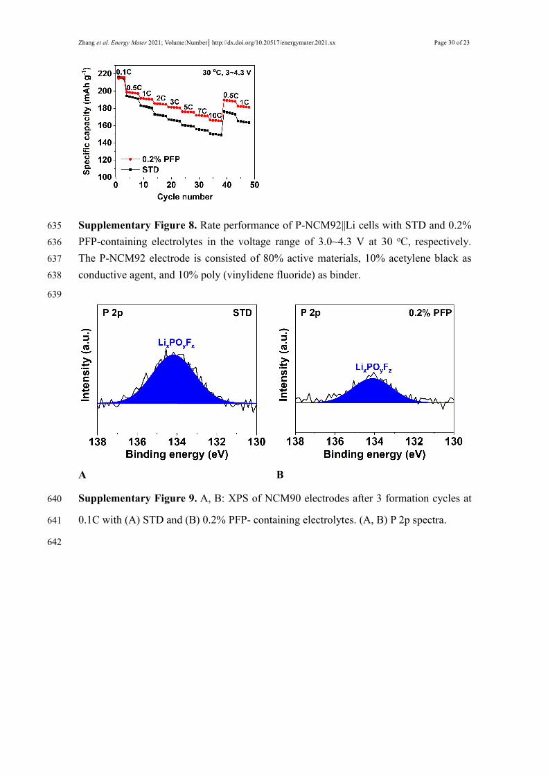
obviously improved discharge capacities at high C rates, as displayed in268
Supplementary Figure 8. Meanwhile, high temperature (45 oC) cycling performance269
of the P-NCM92||Li cells is also enhanced when introducing PFP into the electrolyte, as270
shown in Figure 4D. The result suggest that the PFP additive could be broadly applied271
for promoting the interfacial stability of a wide spectrum of NCM cathode electrodes,272
depending on the specific demand for practical application.273
274
275
276
277
Page 11 of 23 Zhang et al. Energy Mater 2021; Volume:Number│http://dx.doi.org/10.20517/energymater.2021.xx
A B
C D
Figure 4. A: Discharge capacity of NCM90||Li cells at various discharge rates at 30 oC;278
B, C: Charge/discharge curves of cells discharging at (B) 5C and (C) 10C rates with and279
without PFP additive. D: Cycling performance of P-NCM92||Li cells with STD and280
0.2% PFP-containing electrolytes in the voltage range of 3.0~4.3 V at 45 oC.281
282
Kinetics of the cathode interfacial film283
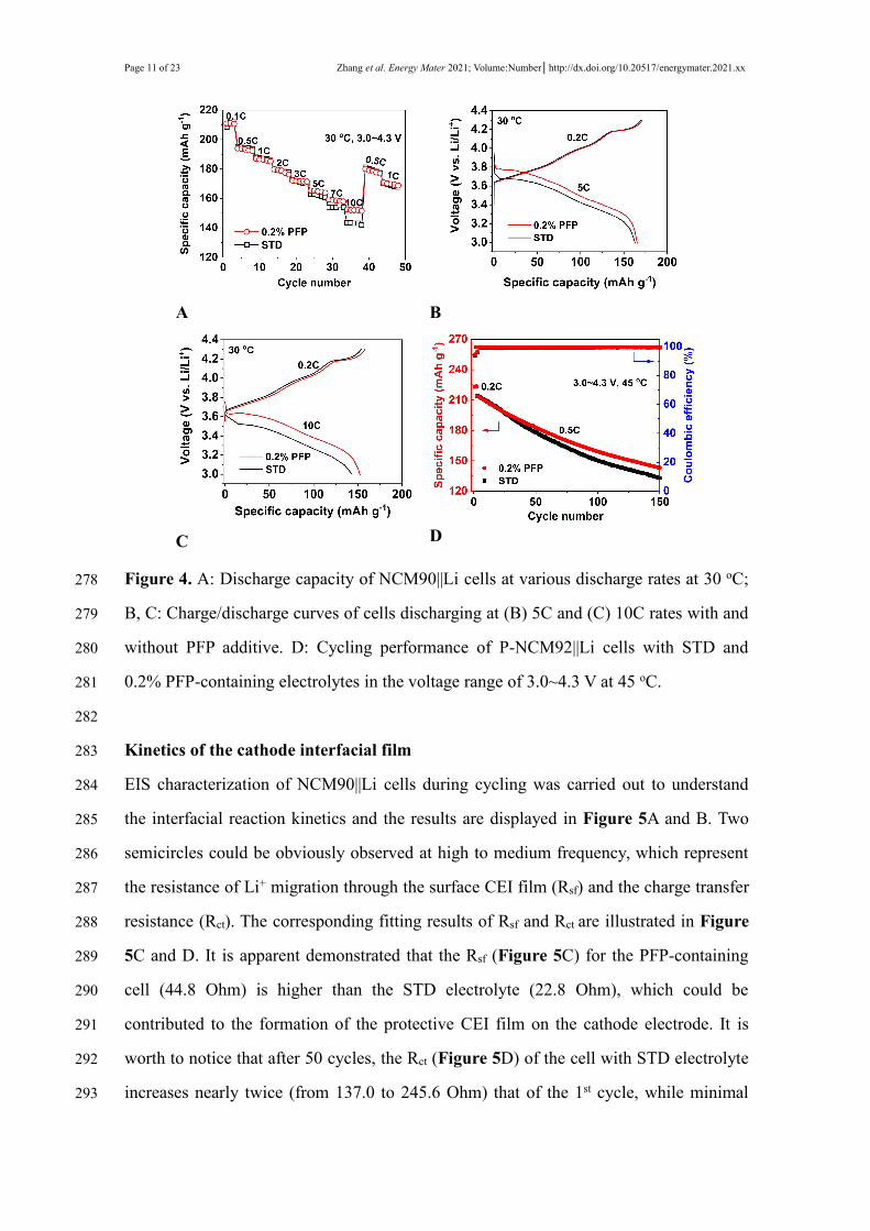
EIS characterization of NCM90||Li cells during cycling was carried out to understand284
the interfacial reaction kinetics and the results are displayed in Figure 5A and B. Two285
semicircles could be obviously observed at high to medium frequency, which represent286
the resistance of Li+ migration through the surface CEI film (Rsf) and the charge transfer287
resistance (Rct). The corresponding fitting results of Rsf and Rct are illustrated in Figure288
5C and D. It is apparent demonstrated that the Rsf (Figure 5C) for the PFP-containing289
cell (44.8 Ohm) is higher than the STD electrolyte (22.8 Ohm), which could be290
contributed to the formation of the protective CEI film on the cathode electrode. It is291
worth to notice that after 50 cycles, the Rct (Figure 5D) of the cell with STD electrolyte292
increases nearly twice (from 137.0 to 245.6 Ohm) that of the 1st cycle, while minimal293
Zhang et al. Energy Mater 2021; Volume:Number│http://dx.doi.org/10.20517/energymater.2021.xx Page 12 of 23
increase in Rct is observed for the PFP-containing cell (from 152.4 to 153.5 Ohm),294
suggesting that the PFP-derived CEI facilitates to maintain lower interfacial resistance,295
therefore, effectively favoring the transfer of Li+ ions through the electrode/electrolyte296
interface.297
298
A B
C D
E F
Figure 5.A, B: Nyquist plots of NCM90||Li cells at various cycles at room temperature,299
A: STD electrolyte, B: 0.2% PFP-containing electrolyte; C, D: Corresponding fitted300
results of Rsf and Rct for NCM90||Li cells; E, F: Relationship between Zre and ω-1/2 at301
low frequency region for cells with (E) STD and (F) 0.2% PFP-containing electrolyte.302
303

Page 13 of 23 Zhang et al. Energy Mater 2021; Volume:Number│http://dx.doi.org/10.20517/energymater.2021.xx
It is well established that the slope of EIS spectra at low frequency is associated with the304
lithium-ion diffusion in the solid electrode (Warburg impedance), which could be used305
to determine the lithium-ion diffusion coefficients (DLi+) based on the Equations (2)306
and (3).[26]307
308
Zre=Rsf+Rct+σω-1/2 (2)
DLi+=R2T2 2A2n4F4C2σ2 (3)
309
where σ represents Warburg impedance coefficient and ω (ω=2π f) is the function of310
frequency (f) for Equation (2) and (3), R stands for the ideal gas constant (8.314 J mol-311
1 K-1), T is thermodynamic temperature in K and T=298.15 K at room temperature, A312
relates to the surface area of the electrode, n is number of electrons, F is Faraday313
constant (96485 C mol-1), and C is the concentration of Li+ for Equation (3). The314
relationships between Zre and ω-1/2 at low frequency region are presented in Figure 5E315
and F.316
317
The calculated results of lithium-ion diffusion coefficients at different cycles are listed318
in Table 1. For PFP-containing electrolyte, the lithium-ion diffusion coefficient is319
higher than that of the STD electrolyte. Particularly, the lithium-ion diffusion coefficient320
of the NCM90 electrode is identified to be 2.25×10⁻¹⁰ cm2 s-1 after 50 cycles in PFP-321
containing electrolyte, which is higher than that in the STD electrolyte (2.13×10⁻¹⁰ cm2322
s-1). This better maintained diffusion kinetics in the presence of PFP additive evidences323
the enhanced stability of CEI layer which prevents the interfacial side reactions and324
suppresses surface structure degradation.325
326
Table1. Calculated results of DLi+ of NCM90||Li cells at different cycles327
Cycle No.STD
DLi+ (cm2 s-1)
0.2% PFP
DLi+ (cm2 s-1)
1st 4.74 x 10⁻¹⁰ 5.62 x 10⁻¹⁰
Zhang et al. Energy Mater 2021; Volume:Number│http://dx.doi.org/10.20517/energymater.2021.xx Page 14 of 23
10th 1.85 x 10⁻¹⁰ 6.74 x 10⁻¹⁰
50th 2.13 x 10⁻¹⁰ 2.25 x 10⁻¹⁰
328
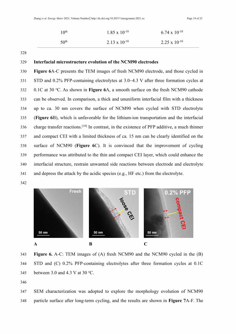
Interfacial microstructure evolution of the NCM90 electrodes329
Figure 6A-C presents the TEM images of fresh NCM90 electrode, and those cycled in330
STD and 0.2% PFP-containing electrolytes at 3.0~4.3 V after three formation cycles at331
0.1C at 30 oC. As shown in Figure 6A, a smooth surface on the fresh NCM90 cathode332
can be observed. In comparison, a thick and ununiform interfacial film with a thickness333
up to ca. 30 nm covers the surface of NCM90 when cycled with STD electrolyte334
(Figure 6B), which is unfavorable for the lithium-ion transportation and the interfacial335
charge transfer reactions.[10] In contrast, in the existence of PFP additive, a much thinner336
and compact CEI with a limited thickness of ca. 15 nm can be clearly identified on the337
surface of NCM90 (Figure 6C). It is convinced that the improvement of cycling338
performance was attributed to the thin and compact CEI layer, which could enhance the339
interfacial structure, restrain unwanted side reactions between electrode and electrolyte340
and depress the attack by the acidic species (e.g., HF etc.) from the electrolyte.341
342
A B C
Figure 6. A-C: TEM images of (A) fresh NCM90 and the NCM90 cycled in the (B)343
STD and (C) 0.2% PFP-containing electrolytes after three formation cycles at 0.1C344
between 3.0 and 4.3 V at 30 oC.345
346
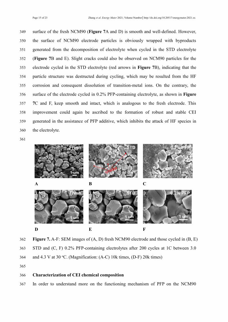
SEM characterization was adopted to explore the morphology evolution of NCM90347
particle surface after long-term cycling, and the results are shown in Figure 7A-F. The348
Page 15 of 23 Zhang et al. Energy Mater 2021; Volume:Number│http://dx.doi.org/10.20517/energymater.2021.xx
surface of the fresh NCM90 (Figure 7A and D) is smooth and well-defined. However,349
the surface of NCM90 electrode particles is obviously wrapped with byproducts350
generated from the decomposition of electrolyte when cycled in the STD electrolyte351
(Figure 7B and E). Slight cracks could also be observed on NCM90 particles for the352
electrode cycled in the STD electrolyte (red arrows in Figure 7B), indicating that the353
particle structure was destructed during cycling, which may be resulted from the HF354
corrosion and consequent dissolution of transition-metal ions. On the contrary, the355
surface of the electrode cycled in 0.2% PFP-containing electrolyte, as shown in Figure356
7C and F, keep smooth and intact, which is analogous to the fresh electrode. This357
improvement could again be ascribed to the formation of robust and stable CEI358
generated in the assistance of PFP additive, which inhibits the attack of HF species in359
the electrolyte.360
361
A B C
D E F
Figure 7.A-F: SEM images of (A, D) fresh NCM90 electrode and those cycled in (B, E)362
STD and (C, F) 0.2% PFP-containing electrolytes after 200 cycles at 1C between 3.0363
and 4.3 V at 30 oC. (Magnification: (A-C) 10k times, (D-F) 20k times)364
365
Characterization of CEI chemical composition366
In order to understand more on the functioning mechanism of PFP on the NCM90367
Zhang et al. Energy Mater 2021; Volume:Number│http://dx.doi.org/10.20517/energymater.2021.xx Page 16 of 23
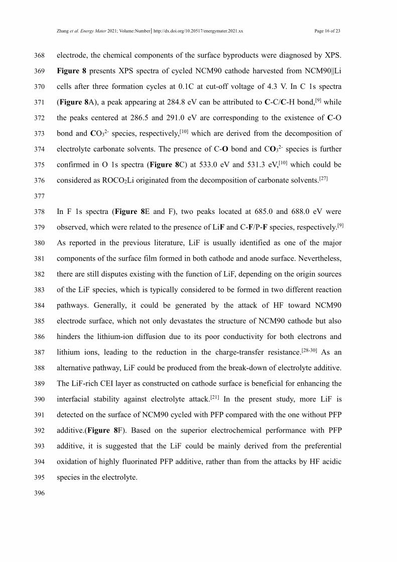
electrode, the chemical components of the surface byproducts were diagnosed by XPS.368
Figure 8 presents XPS spectra of cycled NCM90 cathode harvested from NCM90||Li369
cells after three formation cycles at 0.1C at cut-off voltage of 4.3 V. In C 1s spectra370
(Figure 8A), a peak appearing at 284.8 eV can be attributed to C-C/C-H bond,[9] while371
the peaks centered at 286.5 and 291.0 eV are corresponding to the existence of C-O372
bond and CO32- species, respectively,[10] which are derived from the decomposition of373
electrolyte carbonate solvents. The presence of C-O bond and CO32- species is further374
confirmed in O 1s spectra (Figure 8C) at 533.0 eV and 531.3 eV,[10] which could be375
considered as ROCO2Li originated from the decomposition of carbonate solvents.[27]376
377
In F 1s spectra (Figure 8E and F), two peaks located at 685.0 and 688.0 eV were378
observed, which were related to the presence of LiF and C-F/P-F species, respectively.[9]379
As reported in the previous literature, LiF is usually identified as one of the major380
components of the surface film formed in both cathode and anode surface. Nevertheless,381
there are still disputes existing with the function of LiF, depending on the origin sources382
of the LiF species, which is typically considered to be formed in two different reaction383
pathways. Generally, it could be generated by the attack of HF toward NCM90384
electrode surface, which not only devastates the structure of NCM90 cathode but also385
hinders the lithium-ion diffusion due to its poor conductivity for both electrons and386
lithium ions, leading to the reduction in the charge-transfer resistance.[28-30] As an387
alternative pathway, LiF could be produced from the break-down of electrolyte additive.388
The LiF-rich CEI layer as constructed on cathode surface is beneficial for enhancing the389
interfacial stability against electrolyte attack.[21] In the present study, more LiF is390
detected on the surface of NCM90 cycled with PFP compared with the one without PFP391
additive.(Figure 8F). Based on the superior electrochemical performance with PFP392
additive, it is suggested that the LiF could be mainly derived from the preferential393
oxidation of highly fluorinated PFP additive, rather than from the attacks by HF acidic394
species in the electrolyte.395
396
Page 17 of 23 Zhang et al. Energy Mater 2021; Volume:Number│http://dx.doi.org/10.20517/energymater.2021.xx
A B
C D
E F
G H
Figure 8. A-H: XPS of NCM90 electrodes after 3 formation cycles at 0.1C with (A, C,397
E, G) STD and (B, D, F, H) 0.2% PFP- containing electrolytes. (A, B) C 1s spectra, (C,398
D) O 1s spectra, (E, F) F 1s spectra, (G, H) N 1s spectra.399
Zhang et al. Energy Mater 2021; Volume:Number│http://dx.doi.org/10.20517/energymater.2021.xx Page 18 of 23
400
Comparison of the P 2p spectra in the cycled NCM90 with and without PFP additive401
shows that the peak intensity of LixPOyFz decomposed from LiPF6 is lower in the402
presence of PFP than that without additive, as illustrated in Supplementary Figure 9A403
and B. This result further consolidates that the higher LiF peak intensity as detected for404
the CEI film is generated by the PFP additive other than the decomposition of LiPF6. In405
the N 1s spectra (Figure 8G and H), N signal is absent for NCM90 cycled with PFP-406
free electrolyte (Figure 8G). In comparison, there is an obvious N 1s peak located at407
400.5 eV found for NCM90 cycled in PFP-added electrolyte (Figure 8H), which could408
be attributed to pyridinic nitrogen[21] derived from PFP additive. The binding energy of409
the interfacial nitrogen species is higher than that detected for regular pyridinic nitrogen410
at 398.7 eV,[31] which could be explained that a fraction of fluorine atoms are preserved411
during the electrochemical polymerization of PFP additive.412
413
Furthermore, to deeply investigate the mechanism for electrochemical performance414
improvement, the binding dissociation energies (BDE) of C-F located at different415
position of pyridine ring were calculated based on the DFT, as listed in Table 2. The416
results shows that the fluorine atoms at C2 position (Figure 1B) possesses the lowest417
binding dissociation energy, followed by those at C3 and C5 positions, in the case that418
one electron is extracted from the PFP molecule. Therefore, the fluorine atoms at C2,419
C3, C5 are considered more inclined for electrochemical polymerization, leading to the420
formation of F-containing polypyridine and LiF as proposed in Figure 9. Similar421
electrochemical polymerization mechanism has been previously reported for nitrogen-422
heterocyclic compounds[20] and pyrimidine derivatives.[22]423
424
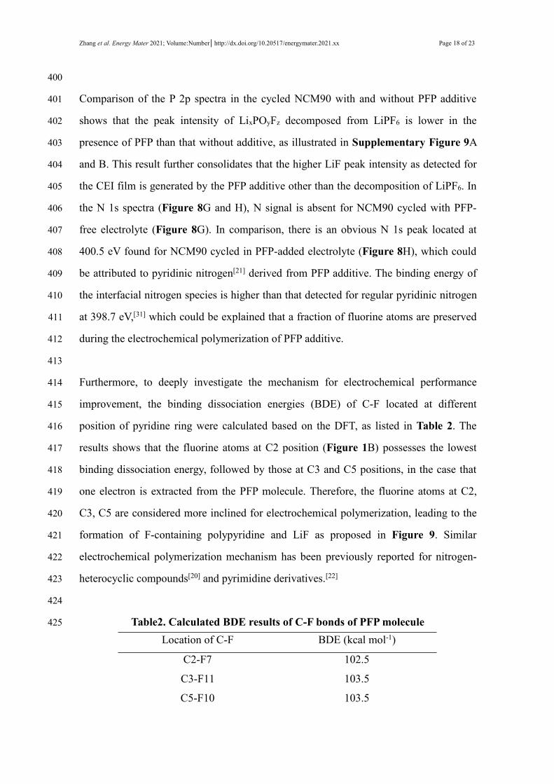
Table2. Calculated BDE results of C-F bonds of PFPmolecule425
Location of C-F BDE (kcal mol-1)
C2-F7 102.5
C3-F11 103.5
C5-F10 103.5
Page 19 of 23 Zhang et al. Energy Mater 2021; Volume:Number│http://dx.doi.org/10.20517/energymater.2021.xx
C1-F8 104.8
C6-F9 104.8
426
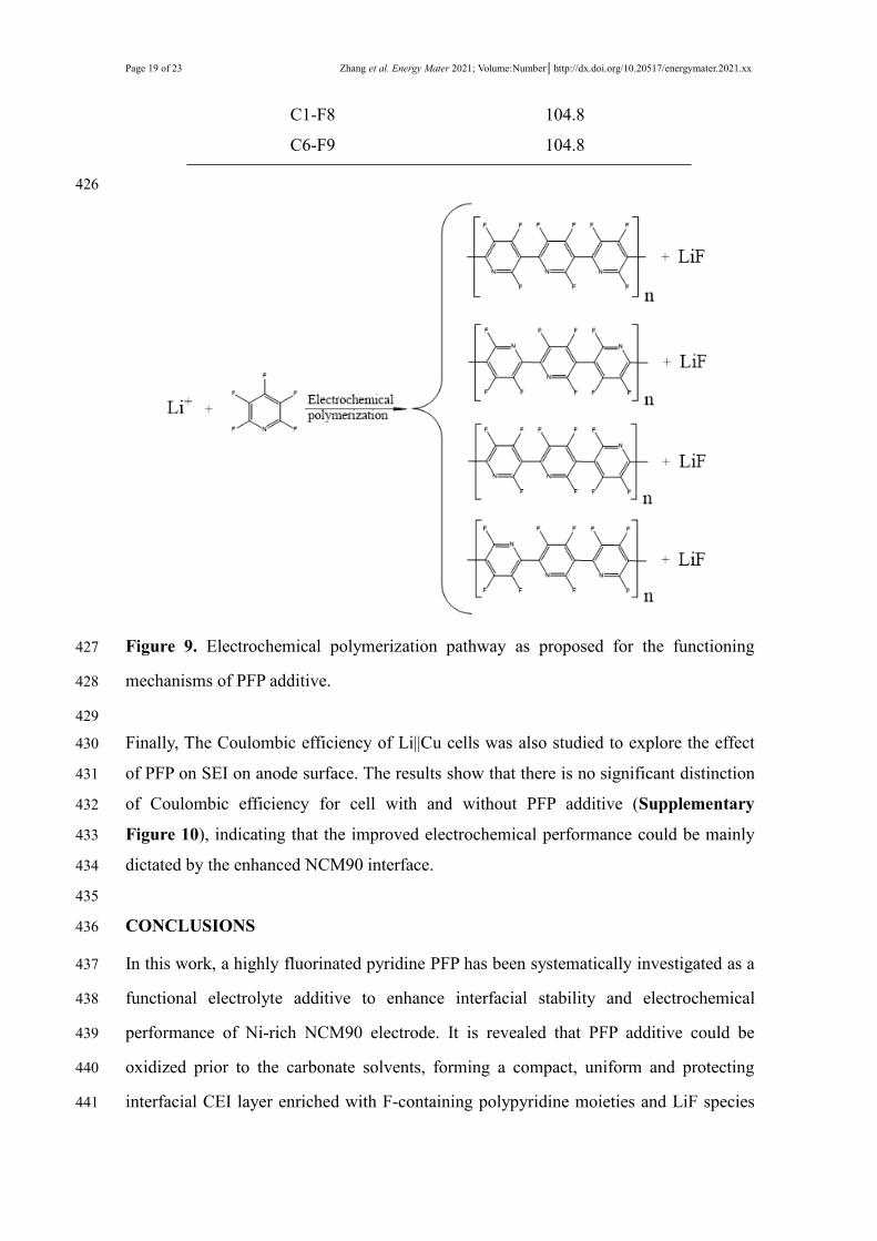
Figure 9. Electrochemical polymerization pathway as proposed for the functioning427
mechanisms of PFP additive.428
429
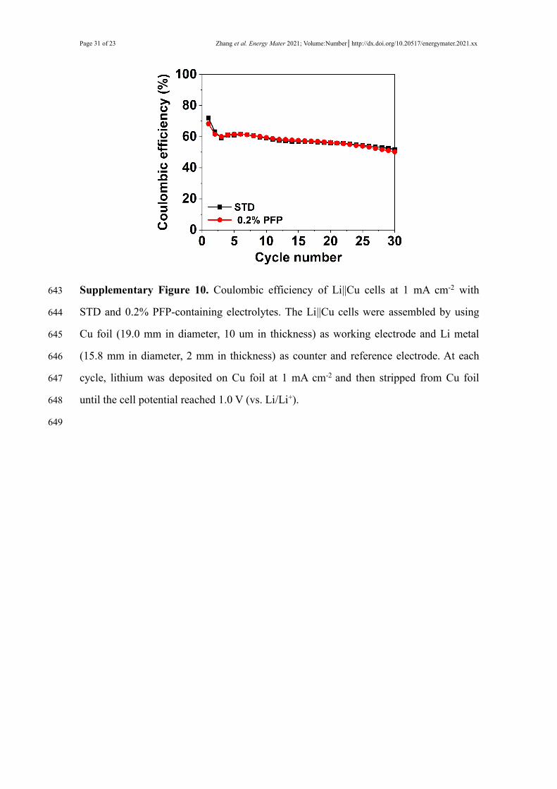
Finally, The Coulombic efficiency of Li||Cu cells was also studied to explore the effect430
of PFP on SEI on anode surface. The results show that there is no significant distinction431
of Coulombic efficiency for cell with and without PFP additive (Supplementary432
Figure 10), indicating that the improved electrochemical performance could be mainly433
dictated by the enhanced NCM90 interface.434
435
CONCLUSIONS436
In this work, a highly fluorinated pyridine PFP has been systematically investigated as a437
functional electrolyte additive to enhance interfacial stability and electrochemical438
performance of Ni-rich NCM90 electrode. It is revealed that PFP additive could be439
oxidized prior to the carbonate solvents, forming a compact, uniform and protecting440
interfacial CEI layer enriched with F-containing polypyridine moieties and LiF species441
Zhang et al. Energy Mater 2021; Volume:Number│http://dx.doi.org/10.20517/energymater.2021.xx Page 20 of 23
on the NCM90 cathode surface. The enhanced CEI layer could effectively inhibit the442
electrolyte decomposition and restrain the corrosion on NCM90 electrode by HF species443
in the electrolyte, giving rise to the improved cycling stability of NCM90 electrode. The444
development and application of this type of functional electrolyte additive could be445
beneficial for the industrial application of Ni-rich NCM for developing high energy446
density LIBs.447
448
DECLARATIONS449
Acknowledgments450
The authors thank Ningbo Ronbay technology Co., Ltd. and Zhangjiagang Guotai451
Huarong Co., Ltd. for kindly supplying the cathode material and electrolyte,452
respectively.453
454
Authors’ contributions455
The manuscript was written with contributions of all authors. All authors have given456
approval to the final version of the manuscript.457
458
Availability of data and materials459
The data supporting our findings can be found in the supplementary information.460
461
Financial support and sponsorship462
The project was supported by the Xiamen University Nanqiang Yang Talent Program,463
and the Natural Science Foundation of Fujian Province of China (No. 2020J06004).464
465
Conflicts of interest466
All authors declared that there are no conflicts of interest.467
468
Ethical approval and consent to participate469
Not applicable.470
471
Consent for publication472
Not applicable.473
474
Page 21 of 23 Zhang et al. Energy Mater 2021; Volume:Number│http://dx.doi.org/10.20517/energymater.2021.xx
Copyright475
© The Author(s) 2021.476
477
REFERENCES478
1. Xia L, Miao H, Zhang CF, Chen GZ, and Yuan JL. Review—recent advances in non-479
aqueous liquid electrolytes containing fluorinated compounds for high energy480
density lithium-ion batteries. Energy Stor Mater, 2021; 38:542-570. DOI:481
10.1016/j.ensm.2021.03.032482
2. Wang SX, Dai A, Cao YL, et al. Enabling stable and high-rate cycling of a Ni-rich483
layered oxide cathode for lithium-ion batteries by modification with an artificial Li+-484
conducting cathode-electrolyte interphase. J Mater Chem A, 2021; 9:11623-11631.485
DOI: 10.1039/d1ta02563e486
3. Wu F, Liu N, Chen L, et al. Improving the reversibility of the H2-H3 phase487
transitions for layered Ni-rich oxide cathode towards retarded structural transition488
and enhanced cycle stability. Nano Energy, 2019; 59:50-57. DOI:489
10.1016/j.nanoen.2019.02.027490
4. Sun HH, Ryu HH, Kim UH, et al. Beyond Doping and Coating: Prospective491
Strategies for Stable High-Capacity Layered Ni-Rich Cathodes. ACS Energy Lett,492
2020; 5:1136-1146. DOI: 10.1021/acsenergylett.0c00191493
5. Fan QL, Lin KJ, Yang SD, et al. Constructing effective TiO2 nano-coating for high-494
voltage Ni-rich cathode materials for lithium ion batteries by precise kinetic control.495
J Power Sources, 2020; 477. DOI: 10.1016/j.jpowsour.2020.228745496
6. Ye ZC, Qiu L, Yang W, et al. Nickel-Rich Layered Cathode Materials for Lithium-497
Ion Batteries. Chemistry, 2021; 27:4249-4269. DOI: 10.1002/chem.202003987498
7. Liu Y, Fan XM, Luo B, et al. Understanding the enhancement effect of boron doping499
on the electrochemical performance of single-crystalline Ni-rich cathode materials. J500
Colloid Interface Sci, 2021; 604:776-784. DOI: 10.1016/j.jcis.2021.07.027501
8. Zheng JM, Yan PF, Estevez L, Wang CM, and Zhang J-G. Effect of calcination502
temperature on the electrochemical properties of nickel-rich LiNi0.76Mn0.14Co0.10O2503
cathodes for lithium-ion batteries. Nano Energy, 2018; 49:538-548. DOI:504

Zhang et al. Energy Mater 2021; Volume:Number│http://dx.doi.org/10.20517/energymater.2021.xx Page 22 of 23
10.1016/j.nanoen.2018.04.077505
9. Liu GP, Xu NB, Zou Y, et al. Stabilizing Ni-Rich LiNi0.83Co0.12Mn0.05O2 with506
Cyclopentyl Isocyanate as a Novel Electrolyte Additive. ACS Appl Mater Interfaces,507
2021; 13:12069−12078. DOI: 10.1021/acsami.1c00443508
10. Zou Y, Zhou K, Liu GP, et al. Enhanced Cycle Life and Rate Capability of Single-509
Crystal, Ni-Rich LiNi0.9Co0.05Mn0.05O2 Enabled by 1,2,4-1H-Triazole Additive. ACS510
Appl Mater Interfaces, 2021; 13:16427−16436. DOI: 10.1021/acsami.1c02043511
11. Chen MH, Zhang ZP, Savilov S, et al. Enhanced structurally stable cathodes by512
surface and grain boundary tailoring of Ni-Rich material with molybdenum trioxide.513
J Power Sources, 2020; 478. DOI: 10.1016/j.jpowsour.2020.229051514
12.Yan PF, Zheng JM, Liu J, et al. Tailoring grain boundary structures and chemistry of515
Ni-rich layered cathodes for enhanced cycle stability of lithium-ion batteries. Nat516
Energy, 2018; 3:600-605. DOI: 10.1038/s41560-018-0191-3517
13.Yoon M, Dong YH, Hwang J, et al. Reactive boride infusion stabilizes Ni-rich518
cathodes for lithium-ion batteries. Nat Energy, 2021; 6:362-371. DOI:519
10.1038/s41560-021-00782-0520
14. Zhang B, Cheng L, Deng P, et al. Effects of transition metal doping on521
electrochemical properties of single-crystalline LiNi0.7Co0.1Mn0.2O2 cathode522
materials for lithium-ion batteries. J Alloys Compd, 2021; 872:159619. DOI:523
10.1016/j.jallcom.2021.159619524
15. Sim SJ, Lee SH, Jin BS, and Kim HS. Effects of lithium tungsten oxide coating on525
LiNi0.90Co0.05Mn0.05O2 cathode material for lithium-ion batteries. J Power Sources,526
2021; 481. DOI: 10.1016/j.jpowsour.2020.229037527
16. Park KJ, Jung HG, Kuo LY, et al. Improved Cycling Stability of528
Li[Ni0.90Co0.05Mn0.05]O2 Through Microstructure Modification by Boron Doping for529
Li-Ion Batteries. Adv Energy Mater, 2018; 8:1801202−1801210. DOI:530
10.1002/aenm.201801202531
17. Shi CG, Shen CH, Peng XX, et al. A special enabler for boosting cyclic life and rate532
capability of LiNi0.8Co0.1Mn0.1O2: Green and simple additive. Nano Energy, 2019;533
65:104084−104093. DOI: 10.1016/j.nanoen.2019.104084534
Page 23 of 23 Zhang et al. Energy Mater 2021; Volume:Number│http://dx.doi.org/10.20517/energymater.2021.xx
18. Tan CL, Yang J, Pan QC, et al. Optimizing interphase structure to enhance535
electrochemical performance of high voltage LiNi0.5Mn1.5O4 cathode via anhydride536
additives. Chem Eng J, 2021; 410. DOI: 10.1016/j.cej.2021.128422537
19. Zhao S, Guo Z, Yan K, et al. Towards high-energy-density lithium-ion batteries:538
Strategies for developing high-capacity lithium-rich cathode materials. Energy Stor539
Mater, 2021; 34:716-734. DOI: 10.1016/j.ensm.2020.11.008540
20. Liao B, Hu XL, Xu MQ, et al. Constructing Unique Cathode Interface by541
Manipulating Functional Groups of Electrolyte Additive for542
Graphite/LiNi0.6Co0.2Mn0.2O2 Cells at High Voltage. J Phys Chem Lett, 2018;543
9:3434−3445. DOI: 10.1021/acs.jpclett.8b01099544
21.Xie ZK, An XW, Wu ZJ, et al. Fluoropyridine family: Bifunction as electrolyte545
solvent and additive to achieve dendrites-free lithium metal batteries. J Mater Sci546
Technol, 2021; 74:119-127. DOI: 10.1016/j.jmst.2020.10.017547
22.Komaba S, Itabashi T, Ohtsuka T, et al. Impact of 2-Vinylpyridine as Electrolyte548
Additive on Surface and Electrochemistry of Graphite for C∕LiMn2O4 Li-Ion Cells. J549
Electrochem Soc, 2005; 152. DOI: 10.1149/1.1885385550
23.Xing LD and Borodin O. Oxidation induced decomposition of ethylene carbonate551
from DFT calculations--importance of explicitly treating surrounding solvent. Phys552
Chem Chem Phys, 2012; 14:12838-43. DOI: 10.1039/c2cp41103b553
24. Leggesse EG and Jiang JC. Theoretical study of the reductive decomposition of554
ethylene sulfite: a film-forming electrolyte additive in lithium ion batteries. J Phys555
ChemA, 2012; 116:11025-33. DOI: 10.1021/jp3081996556
25.Noh HJ, Youn S, Yoon CS, and Sun Y-K. Comparison of the structural and557
electrochemical properties of layered Li[NixCoyMnz]O2 (x = 1/3, 0.5, 0.6, 0.7, 0.8558
and 0.85) cathode material for lithium-ion batteries. J. Power Sources, 2013;559
233:121−130. DOI: 10.1016/j.jpowsour.2013.01.063560
26. Zheng FH, Ou X, Pan QC, et al. Nanoscale gadolinium doped ceria (GDC) surface561
modification of Li-rich layered oxide as a high performance cathode material for562
lithium ion batteries. Chemical Engineering Journal, 2018; 334:497-507. DOI:563
Zhang et al. Energy Mater 2021; Volume:Number│http://dx.doi.org/10.20517/energymater.2021.xx Page 24 of 23
10.1016/j.cej.2017.10.050564
27. Zheng JM, Yan PF, Mei DH, et al. Highly Stable Operation of Lithium Metal565
Batteries Enabled by the Formation of a Transient High-Concentration Electrolyte566
Layer. Adv. Energy Mater., 2016; 6:1502151−1502160. DOI:567
10.1002/aenm.201502151568
28. Zuo XX, Fan CJ, Liu JS, et al. Lithium Tetrafluoroborate as an Electrolyte Additive569
to Improve the High Voltage Performance of Lithium-Ion Battery. J Electrochem570
Soc, 2013; 160:A1199-A1204. DOI: 10.1149/2.066308jes571
29. Chen ZH and Amine K. Tris(pentafluorophenyl) Borane as an Additive to Improve572
the Power Capabilities of Lithium-Ion Batteries. J Electrochem Soc, 2006; 153. DOI:573
10.1149/1.2194633574
30. Lee YM, Lee YG, Kang YM, and Cho KY. Nature of Tris(pentafluorophenyl)borane575
as a Functional Additive and Its Contribution to High Rate Performance in Lithium-576
Ion Secondary Battery. Electrochem and Solid-State Lett, 2010; 13. DOI:577
10.1149/1.3329703578
31. Pang Q, Tang JT, Huang H, et al. A nitrogen and sulfur dual-doped carbon derived579
from polyrhodanine@cellulose for advanced lithium-sulfur batteries. Adv Mater,580
2015; 27:6021-6028. DOI: 10.1002/adma.201502467581
582
Page 25 of 23 Zhang et al. Energy Mater 2021; Volume:Number│http://dx.doi.org/10.20517/energymater.2021.xx
Supplementary Material: Enhancing cycle life of Nickel-rich LiNi0.9Co0.05Mn0.05O2583
via a Highly Fluorinated Electrolyte Additive – Pentafluoropyridine584585
MAIN TEXT586
HOMO and LUMO energies of EC, DEC, and PFP with and without solvation with Li+,587
oxidation potential of EC, DEC, and PFP with and without solvation with Li+, dQ/dV588
curves of Si/C anode with different electrolytes, initial charge/discharge curves NCM90589
with different electrolytes, Coulombic efficiency of NCM90||Li cells with different590
electrolytes, cycling performance of NCM90||Li cells at cut-off voltage 4.4 V and 4.5 V,591
dQ/dV curves of NCM90 electrodes with different electrolytes, Cycle performance and592
rate capability of P-NCM92||Li cells with different electrolytes, XPS (P 2p spectra) of593
NCM90 electrodes after 3 formation cycles, Li||Cu cells cycling data, cycling594
performance of NCM90||Li cell with high loading.595
596
Supplementary Table 1. HOMO and LUMO energies of EC, DEC and PFP597
Solvent/Additive EC DEC PFP
HOMO (eV)
Without solvation with Li-8.43 -8.09 -7.70
LUMO (eV)
Without solvation with Li-0.09 -0.12 -0.06
HOMO(eV)
Solvation with Li-9.17 -8.89 -7.96
LUMO(eV)
Solvation with Li-0.66 -0.59 -1.91
598
Supplementary Table 2. Theoretically calculated oxidation potentials of EC, DEC599
and PFP600
Solvent/Additive EC DEC PFP
Potential (V vs. Li/Li+) 6.64 6.42 5.93
Zhang et al. Energy Mater 2021; Volume:Number│http://dx.doi.org/10.20517/energymater.2021.xx Page 26 of 23
Without solvation with Li
Potential (V vs. Li/Li+)
Solvation with Li7.17 6.97 6.10
601
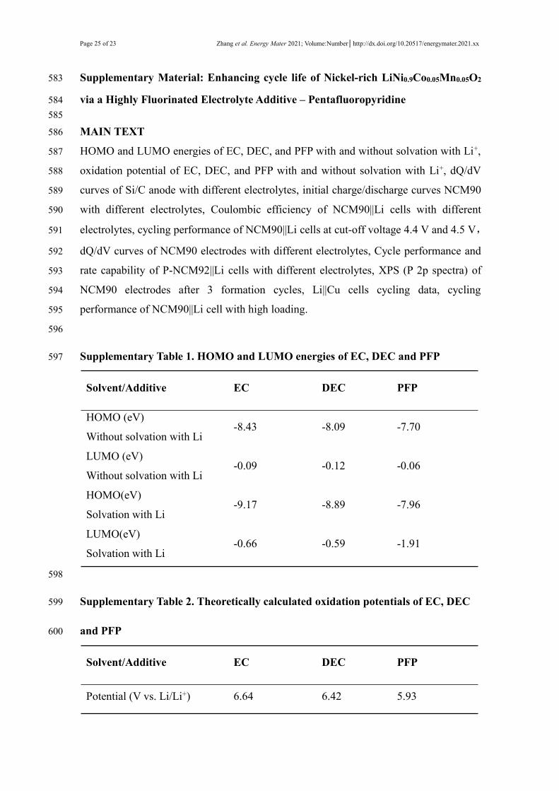
Supplementary Figure 1. The initial dQ/dV curves of Si/C electrode with STD and602
PFP-containing electrolytes at 0.1C (1C = 800 mA g-1). Si/C anode electrodes were603
prepared by casting a slurry of Si/C material, acetylene black and alginate binder with a604
mass ratio of 8:1:1 utilizing deionized water as solvent, on a Cu foil current collector605
with active material loading of ca. 0.5 mg cm-2.606
607
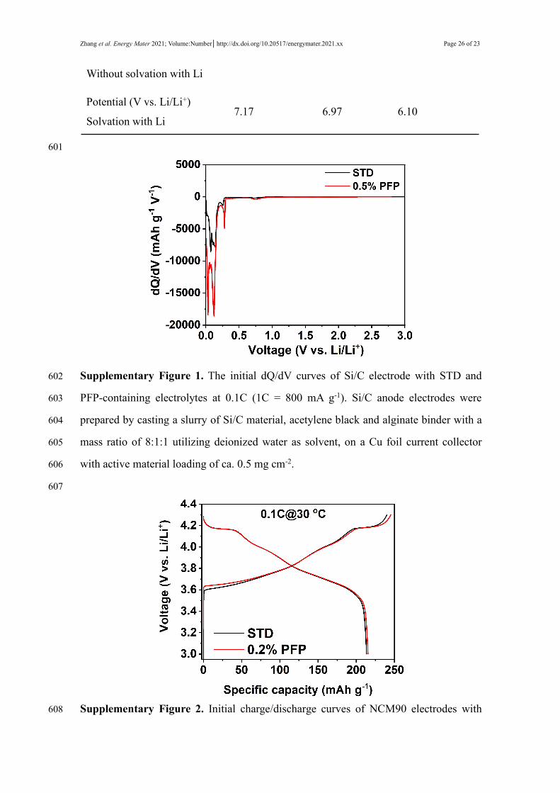
Supplementary Figure 2. Initial charge/discharge curves of NCM90 electrodes with608
Page 27 of 23 Zhang et al. Energy Mater 2021; Volume:Number│http://dx.doi.org/10.20517/energymater.2021.xx
STD and 0.2% PFP-containing electrolytes in the voltage range of 3.0~4.3 V at 30 oC.609
610
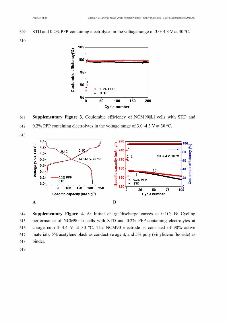
Supplementary Figure 3. Coulombic efficiency of NCM90||Li cells with STD and611
0.2% PFP containing electrolytes in the voltage range of 3.0~4.3 V at 30 oC.612
613
A B
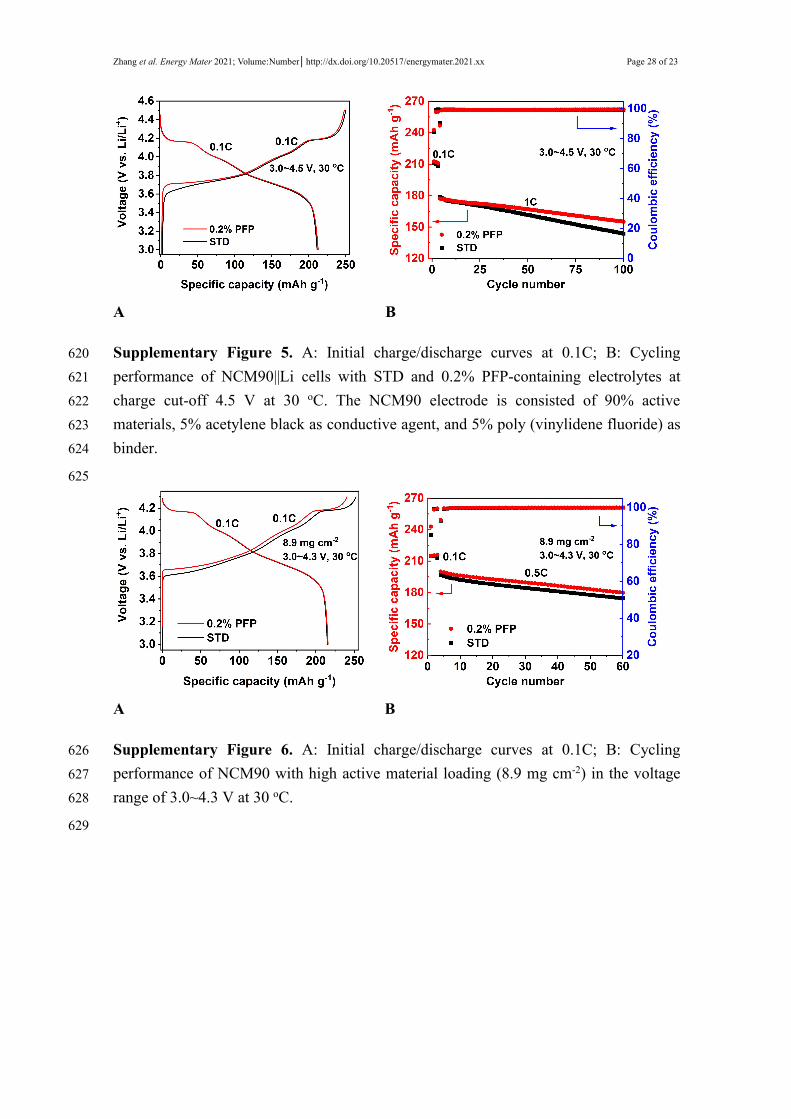
Supplementary Figure 4. A: Initial charge/discharge curves at 0.1C; B: Cycling614
performance of NCM90||Li cells with STD and 0.2% PFP-containing electrolytes at615
charge cut-off 4.4 V at 30 oC. The NCM90 electrode is consisted of 90% active616
materials, 5% acetylene black as conductive agent, and 5% poly (vinylidene fluoride) as617
binder.618
619
Zhang et al. Energy Mater 2021; Volume:Number│http://dx.doi.org/10.20517/energymater.2021.xx Page 28 of 23
A B
Supplementary Figure 5. A: Initial charge/discharge curves at 0.1C; B: Cycling620
performance of NCM90||Li cells with STD and 0.2% PFP-containing electrolytes at621
charge cut-off 4.5 V at 30 oC. The NCM90 electrode is consisted of 90% active622
materials, 5% acetylene black as conductive agent, and 5% poly (vinylidene fluoride) as623
binder.624
625
A B
Supplementary Figure 6. A: Initial charge/discharge curves at 0.1C; B: Cycling626
performance of NCM90 with high active material loading (8.9 mg cm-2) in the voltage627
range of 3.0~4.3 V at 30 oC.628
629
Page 29 of 23 Zhang et al. Energy Mater 2021; Volume:Number│http://dx.doi.org/10.20517/energymater.2021.xx
A
B
CSupplementary Figure 7. A, B: The dQ/dV curves of NCM90||Li cells at 30 oC in the630
voltage range of 3.0~4.3 V with (A) STD and (B) 0.2% PFP-containing electrolyte631
during 200 cycles; C: Comparison of dQ/dV for NCM90||Li cells with and without PFP632
additive at 30 oC at 200 cycles.633
634
Zhang et al. Energy Mater 2021; Volume:Number│http://dx.doi.org/10.20517/energymater.2021.xx Page 30 of 23
Supplementary Figure 8. Rate performance of P-NCM92||Li cells with STD and 0.2%635
PFP-containing electrolytes in the voltage range of 3.0~4.3 V at 30 oC, respectively.636
The P-NCM92 electrode is consisted of 80% active materials, 10% acetylene black as637
conductive agent, and 10% poly (vinylidene fluoride) as binder.638
639
A B
Supplementary Figure 9. A, B: XPS of NCM90 electrodes after 3 formation cycles at640
0.1C with (A) STD and (B) 0.2% PFP- containing electrolytes. (A, B) P 2p spectra.641
642
Page 31 of 23 Zhang et al. Energy Mater 2021; Volume:Number│http://dx.doi.org/10.20517/energymater.2021.xx
Supplementary Figure 10. Coulombic efficiency of Li||Cu cells at 1 mA cm-2 with643
STD and 0.2% PFP-containing electrolytes. The Li||Cu cells were assembled by using644
Cu foil (19.0 mm in diameter, 10 um in thickness) as working electrode and Li metal645
(15.8 mm in diameter, 2 mm in thickness) as counter and reference electrode. At each646
cycle, lithium was deposited on Cu foil at 1 mA cm-2 and then stripped from Cu foil647
until the cell potential reached 1.0 V (vs. Li/Li+).648
649
Related Documents