5 5 P-7136-BGM-EN-A4 08/21 www.bauergears.com AC Variable Speed Energy Efficient Geared Motors Gearboxes & Lubrication Standard mounting positions ............................................................................................................................................................ 55 Postion of the terminal box ............................................................................................................................................................... 57 Position of the terminal box and the cable entry points (BG and BF) .................................................................................................... 57 Position of the terminal box and the cable entry points (BK and BS) ..................................................................................................... 58 Gearboxes ........................................................................................................................................................................................... 59 Radial and axial forces at the output shaft ........................................................................................................................................... 59 Dimensions and fits of output shafts and keyways ............................................................................................................................... 59 Installing transmission elements ........................................................................................................................................................... 59 Gear with solid shaft ............................................................................................................................................................................ 59 Gear with hollow shaft ......................................................................................................................................................................... 59 Shrink disc coupling ............................................................................................................................................................................ 59 Torque restraint .................................................................................................................................................................................... 60 Notes for installing shaft mount gears with hollow shaft and keyway ................................................................................................... 60 Lubricants ........................................................................................................................................................................................... 61 Lubricant quantities .............................................................................................................................................................................. 62 Lubricant quantities, BG-series gears ................................................................................................................................................... 63 Lubricant quantities, BG20-01R ......................................................................................................................................................... 64 Lubricant quantities, BF-series gears ................................................................................................................................................... 65 Lubricant quantities, BK-series gears .................................................................................................................................................. 66 Lubricant quantities, BS-series gears .................................................................................................................................................. 67 Lubricant quantities, pre-stage gears (Z) .............................................................................................................................................. 68 Lubrication quantity for intermediate gear ............................................................................................................................................ 69 Threaded plugs ................................................................................................................................................................................... 70 Position of threaded plugs .................................................................................................................................................................... 70 -BG-series gears ................................................................................................................................................................................. 70 -BG-20-01R........................................................................................................................................................................................ 71 -BF-series gears.................................................................................................................................................................................. 72 -BK-series gears ................................................................................................................................................................................. 73 -BS-series gears ................................................................................................................................................................................. 74 -pre-stage gears (Z)............................................................................................................................................................................. 75 -in the System Cover Design with Standard Geared Motor .................................................................................................................. 76 -in the System Cover Design with foreign motor or gear design with input shaft ................................................................................. 77 53

Welcome message from author
This document is posted to help you gain knowledge. Please leave a comment to let me know what you think about it! Share it to your friends and learn new things together.
Transcript

55
P-7136-BGM-EN-A4 08/21 www.bauergears.com
AC Variable Speed
Energy Efficient Geared Motors
Gearboxes & Lubrication
Standard mounting positions ............................................................................................................................................................55Postion of the terminal box ...............................................................................................................................................................57
Position of the terminal box and the cable entry points (BG and BF) ....................................................................................................57Position of the terminal box and the cable entry points (BK and BS) .....................................................................................................58
Gearboxes ...........................................................................................................................................................................................59Radial and axial forces at the output shaft ...........................................................................................................................................59Dimensions and fits of output shafts and keyways ...............................................................................................................................59Installing transmission elements ...........................................................................................................................................................59Gear with solid shaft ............................................................................................................................................................................59Gear with hollow shaft .........................................................................................................................................................................59Shrink disc coupling ............................................................................................................................................................................59Torque restraint ....................................................................................................................................................................................60Notes for installing shaft mount gears with hollow shaft and keyway ...................................................................................................60
Lubricants ...........................................................................................................................................................................................61Lubricant quantities ..............................................................................................................................................................................62Lubricant quantities, BG-series gears ...................................................................................................................................................63Lubricant quantities, BG20-01R .........................................................................................................................................................64Lubricant quantities, BF-series gears ...................................................................................................................................................65Lubricant quantities, BK-series gears ..................................................................................................................................................66Lubricant quantities, BS-series gears ..................................................................................................................................................67Lubricant quantities, pre-stage gears (Z) ..............................................................................................................................................68Lubrication quantity for intermediate gear ............................................................................................................................................69
Threaded plugs ...................................................................................................................................................................................70Position of threaded plugs ....................................................................................................................................................................70 -BG-series gears .................................................................................................................................................................................70 -BG-20-01R ........................................................................................................................................................................................71 -BF-series gears ..................................................................................................................................................................................72 -BK-series gears .................................................................................................................................................................................73 -BS-series gears .................................................................................................................................................................................74 -pre-stage gears (Z) .............................................................................................................................................................................75 -in the System Cover Design with Standard Geared Motor ..................................................................................................................76 -in the System Cover Design with foreign motor or gear design with input shaft .................................................................................77
53

1
2
3
4
5
6
7
8
9
10
11
12
13
14
15
16
17
18
19
P-7136-BGM-EN-A4 08/21www.bauergears.com
AC Variable Speed
Energy Efficient Geared Motors
54

1
2
3
4
5
6
7
8
9
10
11
12
13
14
15
16
17
18
19
P-7136-BGM-EN-A4 08/21 www.bauergears.com
Gearboxes & LubricationStandard mounting positions
BG series
Gear side (R) (L) (O) (U) (V) (H)
Mounting position H1 H2 H3 H4 V1 V2
BF series
Gear side (U) (R) (L) (O) (V) (H)
Mounting position H4 H1 H2 H3 V1 V2
55

1
2
3
4
5
6
7
8
9
10
11
12
13
14
15
16
17
18
19
P-7136-BGM-EN-A4 08/21www.bauergears.com
Gearboxes & LubricationStandard mounting positions
Reihe BK
Getriebeseite (U) (O) (R) (L) (V) (H)
Einbaulage H1 H2 H3 H4 V1 V2
Reihe BS
Getriebeseite (U) (O) (R) (L) (V) (H)
Einbaulage H1 H2 H3 H4 V1 V2
56

Seite der Leitungszuführung
Lage des Klemmenkastens
Klemmenkasten-Anordnung I / A
C
I
IV
II
IV
I
zum Getriebe
Beispiel für Bezeichnung
AC
A
III
II
A
C
IV
A
C
I
II
BG-KLA
Maßstab
Gepr.
Gez.
Datum
Zeichnungs-Nr.:
Stirnrad-MotoréducteursHelical
Stand: /
La géométrie réelle peut varier par rapport à cette représentation.The actual gearbox design can vary from the geometry shown.Tatsächliche Getriebeausführung kann von der dargestellten Geometrie abweichen.La ejecución real de los equipos puede variar de la geometría representada.В отдельных случаях размеры могут отличаться от указанных на чертеже.
Moto-reductor frontal
THE GEAR MOTOR SPECIALIST
Getriebemotorengama BG Geared Motors Цилиндрическиймотор-редукторcoaxiaux
1:6BG-KLA
ts26.06.2012
006U8
26.06.2012BG-KLA
ts
Beispiel für Bezeichnung
Klemmenkasten-Anordnung I / A
Lage des Klemmenkastens
Seite der Leitungszuführung
A
C
IV
I
II
zum Getriebe
IV
I
II
III
C
A C
A
IV
C
II
A
I
BF-KLA
Maßstab
Gepr.
Gez.
Datum
Zeichnungs-Nr.:
Getriebe-(Motoren)Plan complémentaire motoréducteurGear (Motors)
Stand: /
La géométrie réelle peut varier par rapport à cette représentation.The actual gearbox design can vary from the geometry shown.Tatsächliche Getriebeausführung kann von der dargestellten Geometrie abweichen.La ejecución real de los equipos puede variar de la geometría representada.В отдельных случаях размеры могут отличаться от указанных на чертеже.
Motorreductores-planos
THE GEAR MOTOR SPECIALIST
Zusatzmaßbilderde dimensiones complementariosAdditional Dimension SheetsMотор-редуктор
1:6BF-KLA
ts26.06.2012
006UC
tsBF-KLA
26.06.2012
1
2
3
4
5
6
7
8
9
10
11
12
13
14
15
16
17
18
19
P-7136-BGM-EN-A4 08/21 www.bauergears.com
Gearboxes & Lubrication
The standard position of the terminal box for helical-gear and shaft- mounted geared motors is position I. Cables may be introduced from side A or C.
Position of the terminal box and the cable entry points (BG and BF)
Turning or rotating the gearbox in space in the different mounting positions according to DIN 42950 does not influence the marking as shown. The details of the terminal box always show the position of the terminal box and the cable entry in relation to the gearbox and not in space. The mounting according to DIN 42950 is to be given separately.
Postion of the terminal box
57
CAAC
CAC A
IV
IIII
IIII
I
IV
CAAC
CAC A
I
IV IV
IIII
II II
1
2
3
4
5
6
7
8
9
10
11
12
13
14
15
16
17
18
19
P-7136-BGM-EN-A4 08/21www.bauergears.com
Gearboxes & Lubrication
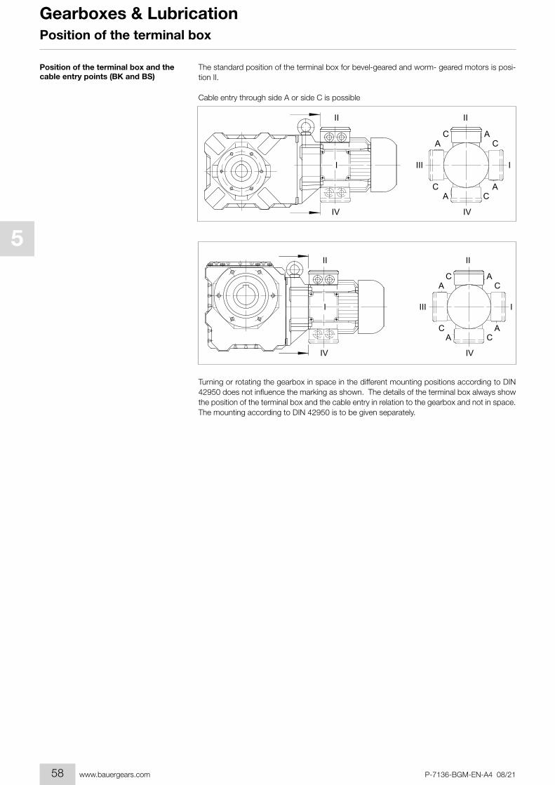
The standard position of the terminal box for bevel-geared and worm- geared motors is posi-tion II.
Cable entry through side A or side C is possible
Position of the terminal box and the cable entry points (BK and BS)
Turning or rotating the gearbox in space in the different mounting positions according to DIN 42950 does not influence the marking as shown. The details of the terminal box always show the position of the terminal box and the cable entry in relation to the gearbox and not in space. The mounting according to DIN 42950 is to be given separately.
Position of the terminal box
58

1
2
3
4
5
6
7
8
9
10
11
12
13
14
15
16
17
18
19
P-7136-BGM-EN-A4 08/21 www.bauergears.com
Gearboxes & Lubrication
The output shafts and output-shaft bearings are matched to the motor torques. It is advisable to locate the drive-transmission element‘s point of application as close as possible to the shaft collar to ensure that the load imposed by external radial forces is not unnecessarily high. Per-missible values for radial forces referred to the output shaft centreline are listed in the selection tables. Please consult us if your application involves extra-high axial loading.
Output shaft and second shaft stub, keyway and key are in compliance with the DIN standards and ISO fits listed below:
Solid shaftShaft diameter to D = 50 mm in ISO k6 (DIN 748 Page1)
as of D = 50 mm in ISO m6 (DIN 748 Page 1)Keyway ISO P9 (DIN 6885 Page 1)Key, height ISO h9 (DIN 6885 Page 1 and DIN 6880)Bore - customer ISO H7
Hollow shaft with keywayBore diameter ISO H7 (DIN 748)Keyway ISO JS9 (DIN 6885 Page 1)Key, height ISO h9 (DIN 6885 Page 1 and DIN 6880)Customer shaft ISO h6
Hollow shaft for shrink-on disc coupling (SSV)Outside diameter ISO f7Inside diameter ISO H7Customer shaft ISO h6
Note: Gearboxes using torque reaction by means of a flange (Code 2.; 3; 4.; 7.; 8.) or torque arm (Code 5.), must have the side for the torque reaction the same as where the radial force on the output shaft occurs (see rubber buffers for torque arms)! Please consult the factory for other designs.
Always exercise meticulous care when fitting transmission elements onto output shafts and, whenever possible, use the DIN 332 tapped bore provided for this purpose. Fitting is usually easier if the transmission element can be heated to approximately 100° C for installation. Di-mension the locating bore to ISO H7.
Gears with solid shaft at each end (gear code -.3/): alignment of the two keys is subject to the DIN 7168 tolerances, the degree of accuracy is “fine”.
Hollow shafts usually engage solid shafts of the driven machinery. The gear unit must be mounted such as to be free of constraint and be fixed axially (e.g. by means of assembly help acc. following description “notes for installing shaft mount gears with hollow shaft and key-way”). Special contract provision must be made if the hollow shaft has to guide the solid shaft or, for any other reason, close out-of-round tolerance referenced to a point on the gear housing (such as a flange, for instance) is required.
A shrink disc coupling (SSV) can transmit high torque from the non- grooved hub to the smooth shaft. The SSV is easily secured and released, using commercially available bolts. SSVs are the ideal supplement for shaft mount gears. The maximum transmittable torque for the selected shrink discs when fitted and mounted according to instructions is above the breakaway torque of the respective motors classified as standard (for classification of shrink disc sizes see chap-ter 11, 12, 13 “Additional dimensional drawings for Shrink disc coupling)
Radial and axial forces at the output shaft
Dimensions and fits of output shafts and keyways
Installing transmission elements
Gear with solid shaft
Gear with hollow shaft
Shrink disc coupling
Gearboxes
59
1
2
3
4
5
6
7
8
9
10
11
12
13
14
15
16
17
18
19
P-7136-BGM-EN-A4 08/21www.bauergears.com
Gearboxes & Lubrication
Detailed information on shaft-mounted gear units, bevel-gear units and worm-gear units is available (see chaper 11, 12., 13 dimensional drawings “Tools for fitting shaft-mounted gear with hollow shaft and keyway”).
The lifetime of the gearbox lubricant increases the better it is protected from negative envi-ronmental influences. Should the oil level or the gearbox ratio cause a very high lubricant temperature, the gearbox will be supplied as standard with a breather plug. Either on request or for corresponding high ambient temperatures, all gearboxes from size 10 can be supplied with a breather plug.
For the position of the threaded plugs see chapter 5 theraded plugs.
All size 10 and larger gears are available with double seals for the output shaft on request and at extra cost. Double seals are particularly effective if the output shaft points down and as protection against external influences
Gear ventilation
Output shaft seals
Shaft-mounted geared motors require a suitable torque restraint to resist the reaction torque. Shaft-mounted gears have cast torque arms as standard. Bevel gears and worm gears are available with bolt-on torque arms on request. The torque arm is screwed onto the front “V” on the side of the gear unit. It is always important to ensure that the torque arm does not create excessive constraining forces due to the driven shaft running untrue, for example. Excessive play can result in excessive shock torques in switching or reversing operations. Consequently, we recommend the use of pre-tensioned rubber damping elements. These rubber buffers are part of the scope of supply for designs with a torque arm (see chaper 11, 12., 13 dimensional drawings “Rubber buffer for torque restraint”)
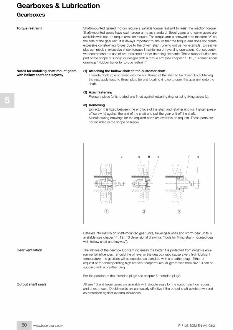
(1) Attaching the hollow shaft to the customer shaft Threaded bolt (d) is screwed into the end thread of the shaft to be driven. By tightening
the nut, apply force to thrust plate (b) and locating ring (c) to draw the gear unit onto the shaft.
(2) Axial fastening Pressure piece (b) is rotated and fitted against retaining ring (c) using fixing screw (a).
(3) Removing Extractor (f) is fitted between the end face of the shaft and retainer ring (c). Tighten press-
off screw (e) against the end of the shaft and pull the gear unit off the shaft. Manufacturing drawings for the required parts are available on request. These parts are
not included in the scope of supply.
Torque restraint
Notes for installing shaft mount gears with hollow shaft and keyway
Gearboxes
60
1
2
3
4
5
6
7
8
9
10
11
12
13
14
15
16
17
18
19
P-7136-BGM-EN-A4 08/21 www.bauergears.com
Gearboxes & Lubrication
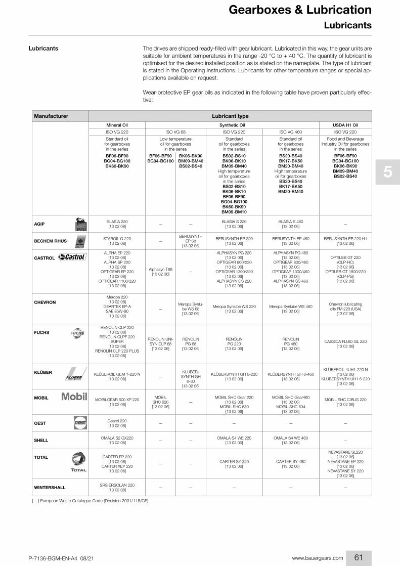
The drives are shipped ready-filled with gear lubricant. Lubricated in this way, the gear units are suitable for ambient temperatures in the range -20 °C to + 40 °C. The quantity of lubricant is optimised for the desired installed position as is stated on the nameplate. The type of lubricant is stated in the Operating Instructions. Lubricants for other temperature ranges or special ap-plications available on request.
Wear-protective EP gear oils as indicated in the following table have proven particularly effec-tive:
Lubricants
AGIP BLASIA 220[13 02 08] — — BLASIA S 220
[13 02 06]BLASIA S 460
[13 02 06] —
BECHEM RHUS STAROIL G 220[13 02 08] —
BERUSYNTH EP 68
[13 02 06]
BERUSYNTH EP 220[13 02 06]
BERUSYNTH EP 460[13 02 06]
BERUSYNTH EP 220 H1[13 02 06]
CASTROLALPHA EP 220
[13 02 08]ALPHA SP 220
[13 02 08]OPTIGEAR EP 220
[13 02 08]OPTIGEAR 1100/220
[13 02 08]
Alphasyn T68[13 02 06] —
ALPHASYN PG 220[13 02 06]
OPTIGEAR 800/220[13 02 06]
OPTIGEAR 1300/220[13 02 06]
ALPHASYN GS 220[13 02 06]
ALPHASYN PG 460[13 02 06]
OPTIGEAR 800/460[13 02 06]
OPTIGEAR 1300/460[13 02 06]
ALPHASYN GS 460[13 02 06]
OPTILEB GT 220(CLP-HC)[13 02 06]
OPTILEB GT 1800/220(CLP-PG)[13 02 08]
CHEVRONMeropa 220[13 02 08]
GEARTEX EP-A SAE 85W-90
[13 02 06]
—Meropa Synlu-
be WS 68[13 02 06]
Meropa Synlube WS 220[13 02 06]
Meropa Synlube WS 460[13 02 06]
Chevron lubricating oils FM 220 (USA)
[13 02 06]
FUCHSRENOLIN CLP 220
[13 02 08]RENOLIN CLPF 220
SUPER[13 02 08]
RENOLIN CLP 220 PLUS[13 02 08]
RENOLIN UNI-SYN CLP 68[13 02 06]
RENOLIN PG 68
[13 02 06]
RENOLIN PG 220
[13 02 06]
RENOLIN PG 460
[13 02 06]
CASSIDA FLUID GL 220[13 02 06]
KLÜBER KLÜBEROIL GEM 1-220 N[13 02 08] —
KLÜBER-SYNTH GH
6-80[13 02 06]
KLÜBERSYNTH GH 6-220[13 02 06]
KLÜBERSYNTH GH 6-460[13 02 06]
KLÜBEROIL 4UH1-220 N[13 02 06]
KLÜBERSYNTH UH1 6-220[13 02 06]
MOBIL MOBILGEAR 600 XP 220[13 02 08]
MOBIL SHC 626[13 02 06]
—MOBIL SHC Gear 220
[13 02 06]MOBIL SHC 630
[13 02 06]
MOBIL SHC Gear460[13 02 06]
MOBIL SHC 634[13 02 06]
MOBIL SHC CIBUS 220[13 02 06]
OEST Gearol 220[13 02 06] — — — — —
SHELL OMALA S2 GX220[13 02 08] — — OMALA S4 WE 220
[13 02 06]OMALA S4 WE 460
[13 02 06] —
TOTAL CARTER EP 220[13 02 08]
CARTER XEP 220[13 02 06]
— — CARTER SY 220[13 02 06]
CARTER SY 460[13 02 06]
NEVASTANE SL220[13 02 06]
NEVASTANE EP 220[13 02 06]
NEVASTANE SY 220[13 02 06]
WINTERSHALL SRS ERSOLAN 220[13 02 08] — — — — —
Manufacturer Lubricant type
Mineral Oil Synthetic Oil USDA H1 Oil
ISO VG 220 ISO VG 68 ISO VG 220 ISO VG 460 ISO VG 220
Standard oil for gearboxes in the series
Low temperature oil for gearboxes
in the series
Standard oil for gearboxes
in the series
Standard oil for gearboxes in the series
Food and Beverage Industry Oil for gearboxes
in the series
BF06-BF90BG04-BG100BK60-BK90
BF06-BF90BG04-BG100
BK06-BK90BM09-BM40BS02-BS40
BS02-BS10BK06-BK10BM09-BM40
High temperature oil for gearboxes
in the seriesBS02-BS10BK06-BK10BF06-BF90
BG04-BG100BK60-BK90BM09-BM10
BS20-BS40BK17-BK50BM20-BM40
High temperature oil for gearboxes
BS20-BS40BK17-BK50BM20-BM40
BF06-BF90BG04-BG100BK06-BK90BM09-BM40BS02-BS40
[....] European Waste Catalogue Code (Decision 2001/118/CE)
Lubricants
61
1
2
3
4
5
6
7
8
9
10
11
12
13
14
15
16
17
18
19
P-7136-BGM-EN-A4 08/21www.bauergears.com
Gearboxes & Lubrication
Important:Synthetic gear oils of a Polyglykol base (e.g. PGLP…) must be disposed of separately to min-eral oil as Special Waste .
So long as the ambient temperature does not fall below – 20 °C the international definition of the viscosity class at 40 °C according to ISO 3448 and DIN 51519 ISO the viscosity class VG220 (SAE90) is recommended according, in North America AGMA 5EP.
For lower temperatures it is recommended to use oils of a lower nominal viscosity with a cor-responding better starting characteristic, for instance a PGLP with a nominal viscosity VG68 (SAE80) or AGMA 2EP respectively. These types of oil can already be necessary at a tempera-ture around the freezing point, if the break away torque of a drive is reduced by some smooth starting device or if the motor has a relatively low power
The preferred quantity of lubricant for the planned type of installation is stated on the motor‘s rating plate (symbol “oil can”). When topping up care should be taken to ensure that, depend-ing on the fitting position, gearwheels and rolling contact bearings positioned at the top are also properly oiled. In special versions the oil level mark should be noted. Information about the quantity of lubricant required for other types of installation can be obtained from the factory
Lubricant quantities
Lubricants
62

1
2
3
4
5
6
7
8
9
10
11
12
13
14
15
16
17
18
19
P-7136-BGM-EN-A4 08/21 www.bauergears.com
Gearboxes & Lubrication
Lubricant quantities, BG-series gears
Lubricants
H2 H3H1H4 H6H5H2 H3H1H4 H6H5H2 H3H1H4 H6H5H2 H3H1H4 H6H5H2 H3H1H4 H6H5
H2 H3H1H4 H6H5
H4 H1 H2 H3 V1 V2
BG04* 0,03 0,03 0,03 0,03 0,05 0,05
** 0,05 0,05 0,05 0,05 0,1 0,05
BG05* 0,05 0,05 0,05 0,05 0,08 0,08
** 0,08 0,08 0,08 0,08 0,16 0,8
BG06* 0,08 0,08 0,08 0,08 0,15 0,15
** 0,12 0,12 0,12 0,12 0,24 0,15
BG10* 0,65 0,65 0,65 0,85 1,05 0,85
** 0,45 0,45 0,45 0,6 0,75 0,6
BG15 ** 0,4 0,4 0,4 0,35 0,62 0,55
BG20* 0,8 0,8 0,8 1,1 1,4 1,1
** 0,6 0,6 0,6 1,0 1,15 0,9
BG30* 1,0 1,0 1,0 1,7 2,4 1,6
** 1,0 1,0 1,0 1,7 2,3 1,7
BG40* 1,7 1,7 1,7 2,5 3,5 2,1
** 1,7 1,7 1,7 2,5 3,5 2,1
BG50* 3,0 3,0 3,0 4,5 5,5 3,3
** 3,0 3,0 3,0 4,5 5,5 3,3
BG60* 5,5 5,5 5,5 7,0 10,9 6,4
** 5,5 5,5 5,5 7,0 10,9 6,4
BG70 6,5 6,5 6,5 8,0 13,5 9,0
BG80 11,0 11,0 11,0 11,0 22,5 15,0
BG90 19,0 19,0 19,0 19,0 40,0 26,0
BG100 35,0 35,0 55,0 50,0 66,0 50,0
Gear-housing with fl ange or footFlange (Code-2./Code-3./Code-4./Code-7.)
Foot with threaded holes (Code -6.)
Foot with clearance holes (Code-9.)
Completely machined (Code -8.)
Foot housingcast foot with clearance holes (Code -1.)
Gearbox type
* Flange Housing
** Foot Housing
Lubrication quantity in litre
63

1
2
3
4
5
6
7
8
9
10
11
12
13
14
15
16
17
18
19
P-7136-BGM-EN-A4 08/21www.bauergears.com
Gearboxes & Lubrication
H1 H2 H3 H4 V1 V2
BF06 0,25 0,25 0,25 0,37 0,35 0,3
BF10 0,85 0,85 0,85 1,1 1,45 1,5
BF20 1,3 1,3 1,3 1,7 2,2 2,25
BF30 1,7 1,7 1,7 2,2 3,2 3,0
BF40 2,7 2,7 2,7 3,5 4,9 4,8
BF50 3,8 3,8 3,8 5,0 6,7 6,7
BF60 6,7 6,7 6,7 9,0 12,3 12,0
BF70 12,2 12,2 12,2 16,0 24,2 21,8
BF80 17,0 17,0 17,0 21,0 32,2 27,5
BF90 32,0 32,0 32,0 41,0 62,0 53,0
Gear type
Lubrication quantity in litre
Lubricant quantities, BG20-01R
Lubricants
H4 H1 H2 H3 V1 V2
BG20R 0,8 1,0 0,8 1,4 1,65 1,0
Gearbox type
Lubrication quantity in litre
64
1
2
3
4
5
6
7
8
9
10
11
12
13
14
15
16
17
18
19
P-7136-BGM-EN-A4 08/21 www.bauergears.com
Gearboxes & LubricationLubricants
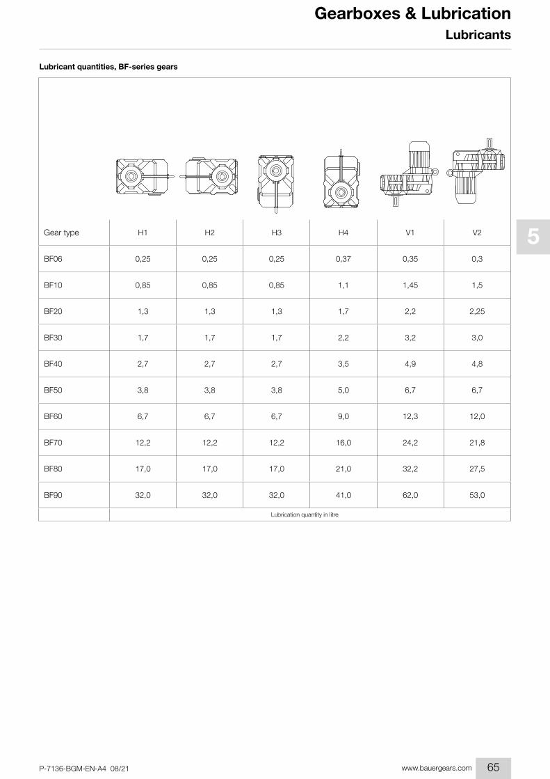
Lubricant quantities, BF-series gears
H1 H2 H3 H4 V1 V2
BF06 0,25 0,25 0,25 0,37 0,35 0,3
BF10 0,85 0,85 0,85 1,1 1,45 1,5
BF20 1,3 1,3 1,3 1,7 2,2 2,25
BF30 1,7 1,7 1,7 2,2 3,2 3,0
BF40 2,7 2,7 2,7 3,5 4,9 4,8
BF50 3,8 3,8 3,8 5,0 6,7 6,7
BF60 6,7 6,7 6,7 9,0 12,3 12,0
BF70 12,2 12,2 12,2 16,0 24,2 21,8
BF80 17,0 17,0 17,0 21,0 32,2 27,5
BF90 32,0 32,0 32,0 41,0 62,0 53,0
Gear type
Lubrication quantity in litre
65
1
2
3
4
5
6
7
8
9
10
11
12
13
14
15
16
17
18
19
P-7136-BGM-EN-A4 08/21www.bauergears.com
Gearboxes & Lubrication
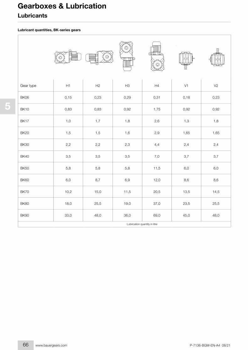
Lubricant quantities, BK-series gears
Lubricants
H1 H2 H3 H4 V1 V2
BK06 0,15 0,23 0,29 0,31 0,18 0,23
BK10 0,83 0,83 0,92 1,75 0,92 0,92
BK17 1,0 1,7 1,8 2,6 1,3 1,8
BK20 1,5 1,5 1,6 2,9 1,65 1,65
BK30 2,2 2,2 2,3 4,4 2,4 2,4
BK40 3,5 3,5 3,5 7,0 3,7 3,7
BK50 5,8 5,8 5,8 11,5 6,0 6,0
BK60 6,0 8,7 6,9 12,0 8,6 8,6
BK70 10,2 15,0 11,5 20,5 13,5 14,5
BK80 18,0 25,5 19,0 37,0 23,5 25,5
BK90 33,0 48,0 36,0 69,0 45,0 48,0
Gear type
Lubrication quantity in litre
66
1
2
3
4
5
6
7
8
9
10
11
12
13
14
15
16
17
18
19
P-7136-BGM-EN-A4 08/21 www.bauergears.com
Gearboxes & LubricationLubricants
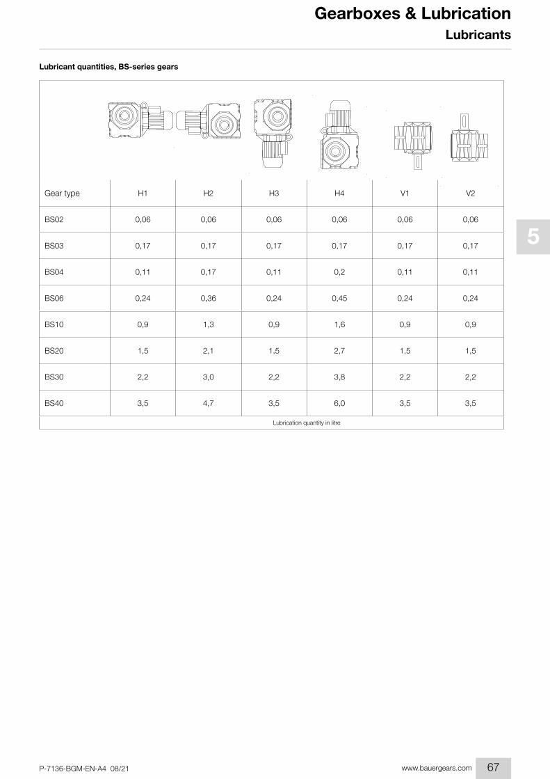
Lubricant quantities, BS-series gears
H1 H2 H3 H4 V1 V2
BS02 0,06 0,06 0,06 0,06 0,06 0,06
BS03 0,17 0,17 0,17 0,17 0,17 0,17
BS04 0,11 0,17 0,11 0,2 0,11 0,11
BS06 0,24 0,36 0,24 0,45 0,24 0,24
BS10 0,9 1,3 0,9 1,6 0,9 0,9
BS20 1,5 2,1 1,5 2,7 1,5 1,5
BS30 2,2 3,0 2,2 3,8 2,2 2,2
BS40 3,5 4,7 3,5 6,0 3,5 3,5
Gear type
Lubrication quantity in litre
67

1
2
3
4
5
6
7
8
9
10
11
12
13
14
15
16
17
18
19
P-7136-BGM-EN-A4 08/21www.bauergears.com
Gearboxes & Lubrication
BFH4 H1 H2 H3 V1 V2
BG
BKH1 V1 V2 H2 H4 H3
BS
BG06G04 BS06G040,03 0,03 0,03 0,03 0,05 0,05
BK06G04
BG10G06 BF10G060,08 0,08 0,08 0,08 0,15 0,15
BK10G06 BS10G06
BG20G06 BF20G060,08 0,08 0,08 0,08 0,15 0,15
BK20G06 BS20G06
BG30G06 BF30G060,08 0,08 0,08 0,08 0,15 0,15
BK30G06 BS30G06
BG40G10 BF40G100,65 0,65 0,65 0,85 1,05 0,85
BK40G10 BS40G10
BG50G10 BF50G100,65 0,65 0,65 0,85 1,05 0,85
BK50G10
BG60G20 BF60G200,8 0,8 0,8 1,1 1,4 1,1
BK60G20
BG70G20 BF70G200,8 0,8 0,8 1,1 1,4 1,1
BK70G20
BG80G40 BF80G401,7 1,7 1,7 2,5 3,3 2,1
BK80G40
BG90G50 BF90G503,0 3,0 3,0 4,5 5,5 3,3
BK90G50 BG100G50
Defi nition of the terminal box positionTerminal box position for intermediate gear is similar to the main gearbox that means
Main gearbox BG, BF terminal box pos. I -> intermediate gearbox terminal box pos. I
Main gearbox BK, BS terminal box pos. II -> intermediate gearbox terminal box pos. II
Mou
ntin
g po
sitio
n of
m
ain
gear
box
Type designation of double gearbox combination
Lubrication quantity in litre
Lubricant quantities, pre-stage gears (Z)
Lubricants
BFH4 H1 H2 H3 V1 V2
BG
BKH1 V1 V2 H2 H4 H3
BS
BF10Z BF10Z0,10 0,05 0,12 0,07 0,16 0,07
BK10Z BS10Z
BG20Z BF20Z0,15 0,07 0,19 0,17 0,27 0,10
BK20Z BS20Z
BG30Z BF30Z
0,2* 0,10 0,35 0,22 0,35 0,19BK30Z BS30Z
BM30Z BM30Z
BG40Z BF40Z
0,32* 0,17 0,50 0,37 0,6 0,32BK40Z BS40Z
BM40Z
BG50Z BF50Z 0,5 0,3 0,92 0,7 1,15 0,5
BK50Z
BG60Z BF60Z0,9 0,5 1,55 1,1 2,0 0,7
BK60Z
BG70Z BF70Z 1,2 0,6 1,8 1,6 2,4 1,4
BK70Z BS70Z
BG80Z BF80Z 3,1 1,3 4,0 2,6 5,2 2,0
BK80Z BS80Z
BG90Z 4,2 1,5 5,4 3,5 7,7 3,0
BK90Z
Gear type
*: with BM30Z/BM40Z the pre-stage lubricant is fi lled via the main gearbox.
Lubrication quantity in litre
68

1
2
3
4
5
6
7
8
9
10
11
12
13
14
15
16
17
18
19
P-7136-BGM-EN-A4 08/21 www.bauergears.com
Gearboxes & LubricationLubricants
Lubrication quantity for intermediate gear
BFH4 H1 H2 H3 V1 V2
BG
BKH1 V1 V2 H2 H4 H3
BS
BG06G04 BS06G040,03 0,03 0,03 0,03 0,05 0,05
BK06G04
BG10G06 BF10G060,08 0,08 0,08 0,08 0,15 0,15
BK10G06 BS10G06
BG20G06 BF20G060,08 0,08 0,08 0,08 0,15 0,15
BK20G06 BS20G06
BG30G06 BF30G060,08 0,08 0,08 0,08 0,15 0,15
BK30G06 BS30G06
BG40G10 BF40G100,65 0,65 0,65 0,85 1,05 0,85
BK40G10 BS40G10
BG50G10 BF50G100,65 0,65 0,65 0,85 1,05 0,85
BK50G10
BG60G20 BF60G200,8 0,8 0,8 1,1 1,4 1,1
BK60G20
BG70G20 BF70G200,8 0,8 0,8 1,1 1,4 1,1
BK70G20
BG80G40 BF80G401,7 1,7 1,7 2,5 3,3 2,1
BK80G40
BG90G50 BF90G503,0 3,0 3,0 4,5 5,5 3,3
BK90G50 BG100G50
Defi nition of the terminal box positionTerminal box position for intermediate gear is similar to the main gearbox that means
Main gearbox BG, BF terminal box pos. I -> intermediate gearbox terminal box pos. I
Main gearbox BK, BS terminal box pos. II -> intermediate gearbox terminal box pos. II
Mou
ntin
g po
sitio
n of
m
ain
gear
box
Type designation of double gearbox combination
Lubrication quantity in litre
BFH4 H1 H2 H3 V1 V2
BG
BKH1 V1 V2 H2 H4 H3
BS
BF10Z BF10Z0,10 0,05 0,12 0,07 0,16 0,07
BK10Z BS10Z
BG20Z BF20Z0,15 0,07 0,19 0,17 0,27 0,10
BK20Z BS20Z
BG30Z BF30Z
0,2* 0,10 0,35 0,22 0,35 0,19BK30Z BS30Z
BM30Z BM30Z
BG40Z BF40Z
0,32* 0,17 0,50 0,37 0,6 0,32BK40Z BS40Z
BM40Z
BG50Z BF50Z 0,5 0,3 0,92 0,7 1,15 0,5
BK50Z
BG60Z BF60Z0,9 0,5 1,55 1,1 2,0 0,7
BK60Z
BG70Z BF70Z 1,2 0,6 1,8 1,6 2,4 1,4
BK70Z BS70Z
BG80Z BF80Z 3,1 1,3 4,0 2,6 5,2 2,0
BK80Z BS80Z
BG90Z 4,2 1,5 5,4 3,5 7,7 3,0
BK90Z
Gear type
*: with BM30Z/BM40Z the pre-stage lubricant is fi lled via the main gearbox.
Lubrication quantity in litre
69
1
2
3
4
5
6
7
8
9
10
11
12
13
14
15
16
17
18
19
P-7136-BGM-EN-A4 08/21www.bauergears.com
Gearboxes & Lubrication
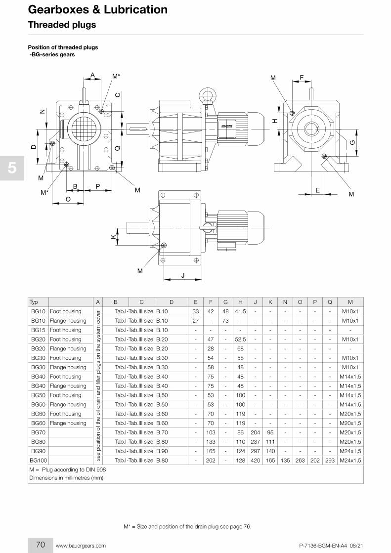
M* = Size and position of the drain plug see page 76.
Position of threaded plugs -BG-series gears
G
ND Q
JM
K
OM*
B P M E M
FA
C
M*
H
M
M
A B C D E F G H J K N O P Q M
BG10 B.10 33 42 48 41,5 - - - - - - M10x1
BG10 B.10 27 - 73 - - - - - - - M10x1
BG15 B.10 - - - - - - - - - - -
BG20 B.20 - 47 - 52,5 - - - - - - M10x1
BG20 B.20 - 28 - 68 - - - - - - -
BG30 B.30 - 54 - 58 - - - - - - M10x1
BG30 B.30 - 58 - 48 - - - - - - M10x1
BG40 B.40 - 75 - 48 - - - - - - M14x1,5
BG40 B.40 - 75 - 48 - - - - - - M14x1,5
BG50 B.50 - 53 - 100 - - - - - - M14x1,5
BG50 B.50 - 53 - 100 - - - - - - M14x1,5
BG60 B.60 - 70 - 119 - - - - - - M20x1,5
BG60 B.60 - 70 - 119 - - - - - - M20x1,5
BG70 B.70 - 103 - 86 204 95 - - - - M20x1,5
BG80 B.80 - 133 - 110 237 111 - - - - M20x1,5
BG90 B.90 - 165 - 124 297 140 - - - - M24x1,5
BG100 B.80 - 202 - 128 420 165 135 263 202 293 M24x1,5
Typ
Foot housing
see
posi
tion
of th
e oi
l dra
in a
nd fi
ller
plug
s on
the
syst
em c
over Tab.I-Tab.III size
Flange housing Tab.I-Tab.III size
Foot housing Tab.I-Tab.III size
Foot housing Tab.I-Tab.III size
Flange housing Tab.I-Tab.III size
Foot housing Tab.I-Tab.III size
Flange housing Tab.I-Tab.III size
Foot housing Tab.I-Tab.III size
Flange housing Tab.I-Tab.III size
Foot housing Tab.I-Tab.III size
Flange housing Tab.I-Tab.III size
Foot housing Tab.I-Tab.III size
Flange housing Tab.I-Tab.III size
Tab.I-Tab.III size
Tab.I-Tab.III size
Tab.I-Tab.III size
Tab.I-Tab.III size
M = Plug according to DIN 908Dimensions in millimetres (mm)
Threaded plugs
70
1
2
3
4
5
6
7
8
9
10
11
12
13
14
15
16
17
18
19
P-7136-BGM-EN-A4 08/21 www.bauergears.com
Gearboxes & Lubrication
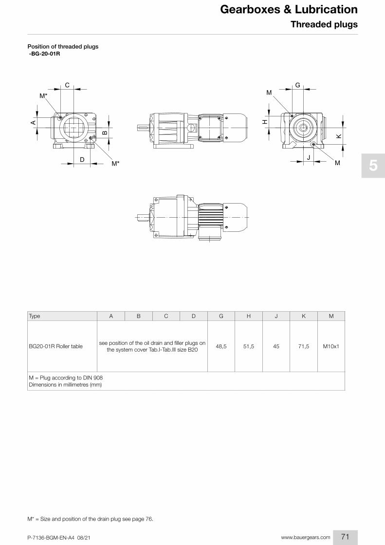
M* = Size and position of the drain plug see page 76.
Position of threaded plugs -BG-20-01R
H
G
A
C
D
B
J
K
M*
M*
M
M
A B C D G H J K M
48,5 51,5 45 71,5 M10x1
Type
BG20-01R Roller tablesee position of the oil drain and fi ller plugs on
the system cover Tab.I-Tab.III size B20
M = Plug according to DIN 908Dimensions in millimetres (mm)
Threaded plugs
G
ND Q
JM
K
OM*
B P M E M
FA
C
M*
H
M
M
A B C D E F G H J K N O P Q M
BG10 B.10 33 42 48 41,5 - - - - - - M10x1
BG10 B.10 27 - 73 - - - - - - - M10x1
BG15 B.10 - - - - - - - - - - -
BG20 B.20 - 47 - 52,5 - - - - - - M10x1
BG20 B.20 - 28 - 68 - - - - - - -
BG30 B.30 - 54 - 58 - - - - - - M10x1
BG30 B.30 - 58 - 48 - - - - - - M10x1
BG40 B.40 - 75 - 48 - - - - - - M14x1,5
BG40 B.40 - 75 - 48 - - - - - - M14x1,5
BG50 B.50 - 53 - 100 - - - - - - M14x1,5
BG50 B.50 - 53 - 100 - - - - - - M14x1,5
BG60 B.60 - 70 - 119 - - - - - - M20x1,5
BG60 B.60 - 70 - 119 - - - - - - M20x1,5
BG70 B.70 - 103 - 86 204 95 - - - - M20x1,5
BG80 B.80 - 133 - 110 237 111 - - - - M20x1,5
BG90 B.90 - 165 - 124 297 140 - - - - M24x1,5
BG100 B.80 - 202 - 128 420 165 135 263 202 293 M24x1,5
Typ
Foot housing
see
posi
tion
of th
e oi
l dra
in a
nd fi
ller
plug
s on
the
syst
em c
over Tab.I-Tab.III size
Flange housing Tab.I-Tab.III size
Foot housing Tab.I-Tab.III size
Foot housing Tab.I-Tab.III size
Flange housing Tab.I-Tab.III size
Foot housing Tab.I-Tab.III size
Flange housing Tab.I-Tab.III size
Foot housing Tab.I-Tab.III size
Flange housing Tab.I-Tab.III size
Foot housing Tab.I-Tab.III size
Flange housing Tab.I-Tab.III size
Foot housing Tab.I-Tab.III size
Flange housing Tab.I-Tab.III size
Tab.I-Tab.III size
Tab.I-Tab.III size
Tab.I-Tab.III size
Tab.I-Tab.III size
M = Plug according to DIN 908Dimensions in millimetres (mm)
71

1
2
3
4
5
6
7
8
9
10
11
12
13
14
15
16
17
18
19
P-7136-BGM-EN-A4 08/21www.bauergears.com
Gearboxes & LubricationThreaded plugs
Position of threaded plugs -BF-series gears
B
M*
A
D
F
M*
C
G
M E
H
M
A B C D E F G H M
BF06
BF10 B.10 64 65 97 28 M10x1
BF20 B.20 77 70 115 30,5 M10x1
BF30 B.30 88 82 125 36,5 M10x1
BF40 B.40 100 86 141 33 M14x1,5
BF50 B.50 120 105 165 42,3 M14x1,5
BF60 B.60 140 145 200 50,5 M20x1,5
BF70 B.70 165 177 235 52,5 M20x1,5
BF80 B.70 145 148 255 123 M20x1,5
BF90 B.80 155 176 347,5 260 M24x1,5
Type
see
posi
tion
of th
e oi
l dra
in a
nd fi
ller
plug
s on
the
syst
em c
over
on request
Tab.I-Tab.III size
Tab.I-Tab.III size
Tab.I-Tab.III size
Tab.I-Tab.III size
Tab.I-Tab.III size
Tab.I-Tab.III size
Tab.I-Tab.III size
Tab.I-Tab.III size
Tab.I-Tab.III size
M = Plug according to DIN 908 Dimensions in millimetres (mm)
M* = Size and position of the drain plug see page 76.
72
1
2
3
4
5
6
7
8
9
10
11
12
13
14
15
16
17
18
19
P-7136-BGM-EN-A4 08/21 www.bauergears.com
Gearboxes & Lubrication
M* = Size and position of the drain plug see page 76.
Threaded plugs
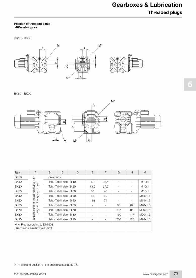
Position of threaded plugs -BK-series gears
BK10 - BK50
BK60 - BK90
D
ME
F
A
C
BM*
M*
D
H
G
M*A
M* B
C
M
A B C D E F G H M
BK06
BK10 B.10 62 32,5 - - M10x1
BK20 B.20 73,5 37,5 - - M10x1
BK30 B.30 80 43 - - M10x1
BK40 B.40 88 49 - - M14x1,5
BK50 B.50 118 74 - - M14x1,5
BK60 B.60 - - 93 87 M20x1,5
BK70 B.70 - - 137 95 M20x1,5
BK80 B.80 - - 150 117 M20x1,5
BK90 B.90 - - 208 135 M24x1,5
Type
see
posi
tion
of th
e oi
l dra
in a
nd fi
ller
plug
s on
the
syst
em c
over
on request
Tab.I-Tab.III size
Tab.I-Tab.III size
Tab.I-Tab.III size
Tab.I-Tab.III size
Tab.I-Tab.III size
Tab.I-Tab.III size
Tab.I-Tab.III size
Tab.I-Tab.III size
Tab.I-Tab.III size
M = Plug according to DIN 908Dimensions in millimetres (mm)
73
1
2
3
4
5
6
7
8
9
10
11
12
13
14
15
16
17
18
19
P-7136-BGM-EN-A4 08/21www.bauergears.com
Gearboxes & Lubrication
M* = Size and position of the drain plug see page 76.
Threaded plugs
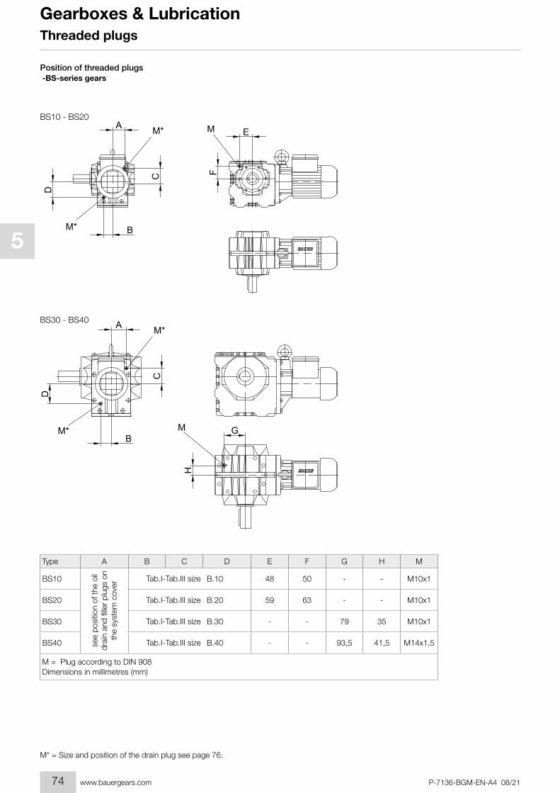
Position of threaded plugs -BS-series gears
BS10 - BS20
BS30 - BS40
A
B
D
M*FC
M* EM
H
G
A
B
D
M*
C
M
M*
A B C D E F G H M
BS10 B.10 48 50 - - M10x1
BS20 B.20 59 63 - - M10x1
BS30 B.30 - - 79 35 M10x1
BS40 B.40 - - 93,5 41,5 M14x1,5
Type
see
posi
tion
of th
e oi
l dr
ain
and
fi lle
r pl
ugs
on
the
syst
em c
over
Tab.I-Tab.III size
Tab.I-Tab.III size
Tab.I-Tab.III size
Tab.I-Tab.III size
M = Plug according to DIN 908Dimensions in millimetres (mm)
74
1
2
3
4
5
6
7
8
9
10
11
12
13
14
15
16
17
18
19
P-7136-BGM-EN-A4 08/21 www.bauergears.com
Gearboxes & Lubrication
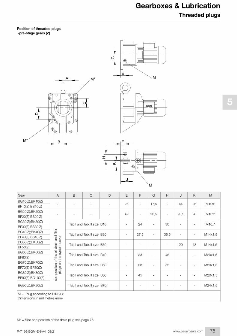
M* = Size and position of the drain plug see page 76.
Threaded plugs
Position of threaded plugs -pre-stage gears (Z)
BM*
K
J
F
H
M
D
EM*
CA
G
M
A B C D E F G H J K M
BG10(Z);BK10(Z)- - - - 25 - 17,5 - 44 25 M10x1
BF10(Z);BS10(Z)
BG20(Z);BK20(Z)- - - - 49 - 28,5 - 23,5 28 M10x1
BF20(Z);BS20(Z)
BG30(Z);BK30(Z)B10 - 24 - 30 - - M10x1
BF30(Z);BS30(Z)
BG40(Z);BK40(Z)B20 - 27,5 - 36,5 - - M14x1,5
BF40(Z);BS40(Z)
BG50(Z);BK50(Z)B30 - - - - 29 43 M14x1,5
BF50(Z)
BG60(Z);BK60(Z)B40 - 33 - 48 - - M20x1,5
BF60(Z)
BG70(Z);BK70(Z)B50 - 38 - 55 - - M20x1,5
BF70(Z);BF80(Z)
BG80(Z);BK80(Z)B60 - 45 - - - - M20x1,5
BF90(Z);BG100(Z)
BG90(Z);BK90(Z) B70 - - - - - - M24x1,5
Gear
see
posi
tion
of th
e oi
l dra
in a
nd fi
ller
plug
s on
the
syst
em c
over
Tab.I and Tab.III size
Tab.I and Tab.III size
Tab.I and Tab.III size
Tab.I and Tab.III size
Tab.I and Tab.III size
Tab.I and Tab.III size
Tab.I and Tab.III size
M = Plug according to DIN 908Dimensions in millimetres (mm)
75
1
2
3
4
5
6
7
8
9
10
11
12
13
14
15
16
17
18
19
P-7136-BGM-EN-A4 08/21www.bauergears.com
Gearboxes & LubricationThreaded plugs
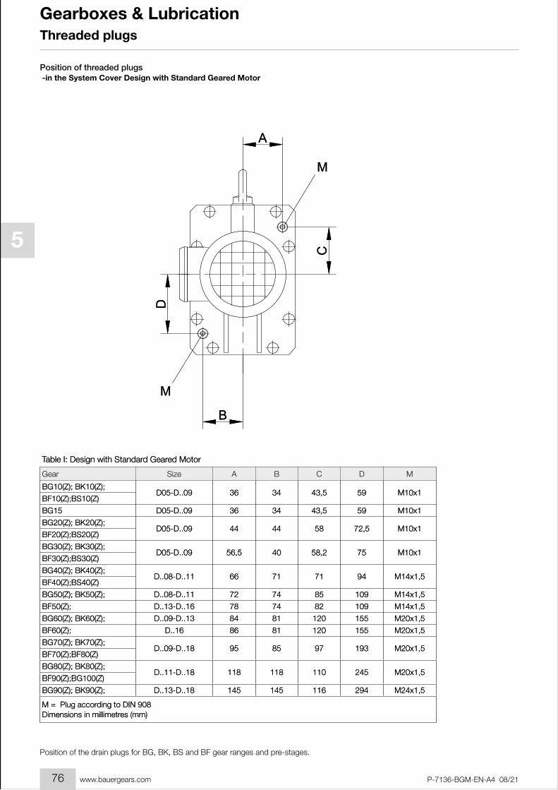
Position of threaded plugs -in the System Cover Design with Standard Geared Motor
D
M
B
C
M
A
A B C D M
BG10(Z); BK10(Z);D05-D..09 36 34 43,5 59 M10x1
BF10(Z);BS10(Z)
BG15 D05-D..09 36 34 43,5 59 M10x1
BG20(Z); BK20(Z);D05-D..09 44 44 58 72,5 M10x1
BF20(Z);BS20(Z)
BG30(Z); BK30(Z);D05-D..09 56,5 40 58,2 75 M10x1
BF30(Z);BS30(Z)
BG40(Z); BK40(Z);D..08-D..11 66 71 71 94 M14x1,5
BF40(Z);BS40(Z)
BG50(Z); BK50(Z); D..08-D..11 72 74 85 109 M14x1,5
BF50(Z); D..13-D..16 78 74 82 109 M14x1,5
BG60(Z); BK60(Z); D..09-D..13 84 81 120 155 M20x1,5
BF60(Z); D..16 86 81 120 155 M20x1,5
BG70(Z); BK70(Z);D..09-D..18 95 85 97 193 M20x1,5
BF70(Z);BF80(Z)
BG80(Z); BK80(Z);D..11-D..18 118 118 110 245 M20x1,5
BF90(Z);BG100(Z)
BG90(Z); BK90(Z); D..13-D..18 145 145 116 294 M24x1,5
Table I: Design with Standard Geared Motor
Gear Size
M = Plug according to DIN 908 Dimensions in millimetres (mm)
Position of the drain plugs for BG, BK, BS and BF gear ranges and pre-stages.
76

1
2
3
4
5
6
7
8
9
10
11
12
13
14
15
16
17
18
19
P-7136-BGM-EN-A4 08/21 www.bauergears.com
Gearboxes & LubricationThreaded plugsThreaded plugs
Position of the drain plugs for BG, BK, BS and BF gear ranges and pre-stages.
D
M
A
B
M
C
A B C D M
BG10(Z); BK10(Z);1,34 1,34 1,59 2,24 M10x1
BF10(Z);BS10(Z)
BG15 1,34 1,34 1,59 2,24 M10x1
BG20(Z); BK20(Z);1,73 1,73 2,24 2,83 M10x1
BF20(Z);BS20(Z)
BG30(Z); BK30(Z);2,30 1,61 2,27 3,03 M10x1
BF30(Z);BS30(Z)
BG40(Z); BK40(Z);2,72 2,87 2,76 3,82 M14x1,5
BF40(Z);BS40(Z)
BG50(Z); BK50(Z);2,95 2,95 3,23 4,33 M14x1,5
BF50(Z);
BG60(Z); BK60(Z);3,31 3,19 4,69 6,10 M20x1,5
BF60(Z);
BG70(Z); BK70(Z);3,78 3,74 3,78 7,60 M20x1,5
BF70(Z);BF80(Z)
BG80(Z); BK80(Z);4,65 4,65 4,33 9,65 M20x1,5
BF90(Z);BG100(Z)
BG90(Z); BK90(Z); 5,71 5,71 4,57 11,57 M24x1,5
Table II: Design with foreign motor or gear design with input shaft
Gear
M = Plug according to DIN 908Dimensions in millimetres (mm)
Position of threaded plugs -in the System Cover Design with foreign motor or gear design with input shaft
77

1
2
3
4
5
6
7
8
9
10
11
12
13
14
15
16
17
18
19
P-7136-BGM-EN-A4 08/21www.bauergears.com
Gearboxes & Lubrication
78
Related Documents