Energy Conversion by Permanent Magnet Machines and Novel Development of the Single Phase Synchronous Permanent Magnet Motor Richard Johnston Strahan B.E.(Hons} A thesis presented for the degree of Doctor of Philosophy in Electrical and Electronic Engineering at the University of Canterbury, Christchurch, New Zealand. September 1998

Welcome message from author
This document is posted to help you gain knowledge. Please leave a comment to let me know what you think about it! Share it to your friends and learn new things together.
Transcript
Energy Conversion by Permanent
Magnet Machines
and
Novel Development of the Single
Phase Synchronous Permanent
Magnet Motor
Richard Johnston Strahan B.E.(Hons}
A thesis presented for the degree of
Doctor of Philosophy
in
Electrical and Electronic Engineering
at the
University of Canterbury,
Christchurch, New Zealand.
September 1998

i;lIGINEERING LIBRARY
ABSTRACT
Energy methods are widely used and well understood for determining the torque or
force in machines which do not contain permanent magnets. Energy methods are
employed to calculate torques or forces of magnetic origin after determination of the
energy stored in the electromechanical coupling field. In this thesis, the energy stored
in a permanent magnet system is defined, and the energy-co energy relationship is
determined. It is shown how residual magnetism can be incorporated into classical
electromechanical coupling theory. It is therefore shown how equations for torques or
forces can be derived for permanent magnet systems using energy methods.
An analytical method of calculating permanent magnet reluctance torque is devel
oped. The method uses an elementary expression for the magnetic field to obtain the
stored energy. This enables an analytical expression for the reluctance torque waveform
to be obtained. The method is demonstrated to provide a powerful and fast design tool.
The method can be generally applied to reluctance torque problems where the airgap
is reasonably smooth.
The single phase synchronous permanent magnet motor is used in domestic appli
ances. It is a motor of very simple construction and high reliability, which is directly
connected to an AC mains supply, and runs at synchronous speed. It is becoming
increasingly used in preference to the shaded pole induction motor. However, its ap
plication is limited by the following characteristics. There is no control over the final
direction of rotation, unless a mechanical blocking device is used. There are rotor po
sitions at which only a very small starting torque is available. The characteristic twice
electrical frequency torque pulsation yields a speed modulation of the same frequency,
which can cause acoustic noise problems. A method of improving torque quality by
improving the motor design is proposed to alleviate these limiting characteristics. This
is achieved by designing a permanent magnet reluctance torque which cancels out the
effect of the backward rotating component of the stator field. In this novel design, the
permanent magnet reluctance torque effectively acts as a second balancing phase.
An unconventional technique for starting a single phase synchronous permanent
magnet motor is demonstrated. This technique uses an inductive reluctance torque,
provided by placing a suitably shaped iron lamination on the rotor, to rotate the rotor
to a position from which starting can occur.

ACKNOWLEDGEMENTS
I am very grateful to a number of people who have enabled me to complete the work
presented herein. I thank Associate Professor David Watson for his advice and patience,
through both my undergraduate and postgraduate years. My interest in electrical
machines gathered momentum as a result of his undergraduate machines course. I
would like to thank Associate Professor Pat Bodger for his advice and encouragement,
and also Associate Professor Harsha Sirisena. I thank Ken Smart for his help in the
machines laboratory. I thank Dr John Smaill for his enthusiasm and assistance in the
mechanical design of my machines.
I am greatly indebted to Dr J.D. Edwards of the University of Sussex, and to Dr
Gerald Altenbernd of the University of Hannover, without whose help this work could
not have been possible. I thank Dr Edwards for the finite element analysis work he
has done for me, and for his valued correspondence. I thank Dr Altenbernd for kindly
answering many questions, and for arranging to send me the single phase motors,
courtesy of Siemens.
I thank my postgraduate friends for their help, particularly Dr Rob Van Nobelen
for his assistance with mathematical matters. Finally, I thank Rosemary for her care
and support during my studies.

CONTENTS
ABSTRACT iii
ACKNOWLEDGEMENTS v
GLOSSARY xiii
PREFACE xvii
CHAPTER 1 INTRODUCTION 1
1.1 Small Electric Motors 1
1.2 The Single Phase Synchronous Permanent Magnet Motor 4
1.2.1 Equations of Motion 5
1.2.2 Displacement Angle "IT and Alternative Designs 7
1.2.3 Moment of Inertia 9
1.2.4 Direction of Rotation 10
1.2.5 Stability 10
1.2.6 Acoustic Noise 12
1.2.7 Summary of Characteristcs 13
1.3 Improving The Motor Characteristics 14
1.3.1 Electronic Commutation 14
1.3.2 Improving Torque Quality 15
1.4 The Unidirectional Single Phase Synchronous PM Motor 17
1.5 A PM Motor with Triangular Reluctance Torque 18
1.6 The EMF/Torque Function 19
CHAPTER 2 ENERGY CONVERSION BY PERMANENT MAGNET MACHINES
2.1 Introduction
2.2 Energy Stored in a Permanent Magnet System
21 21
22
2.3 Co energy of a Permanent Magnet System 27
2.3.1 Stored Energy and Co energy in a Linear PM System 28
2.4 Electromechanical Coupling 31
2.4.1 Classical Electromechanical Coupling 31
2.4.2 Permanent Magnets and Single Energised Winding 35
viii CONTENTS
2.4.3 Permanent Magnets and Multiple Energised Wind
ings 36
2.5 Torque Equations for a Linear Permanent Magnet System 38
2.6 Current Sheet Model of a Permanent Magnet 39
2.7 Energy-Coenergy Relationship 2.7.1 Quasistatic Electromagnetic Equations
2.7.2 Zero Currents
2.7.3 Non-Zero Currents
2.8 Conclusions
CHAPTER 3 A PM MOTOR WITH TRIANGULAR
40 40
41
42
44
RELUCTANCE TORQUE 45 3.1 Introduction 45 3.2 A Physical Implementation of the Triangular Motor 45
3.3 Selection of Magnetic Materials
3.3.1 Non Grain Oriented Silicon Steel
49
49
3.3.2 Permanent Magnet Materials 49
3.3.2.1 Bonded Nd-Fe-B Permanent Magnets 50
3.4 Mechanical Design
3.4.1 Stator and Stator Housing 3.4.2 Rotor and Shaft
51
53 54
3.4.3 Reluctance Plate and Housing 55
3.5 An Analytical Method of Calculating PM Reluctance Torque 56
3.5.1 PM Reluctance Torque and Stored Energy 56
3.5.2 Approximation of the Direction and Magnitude of the Magnetic Flux Density 57
3.5.3 A Comparison to the Maxwell Stress Tensor Method 61
3.6 Design of A Triangular PM Reluctance Torque 63 3.6.1 Rectangular Magnet and Triangular Airgap 63 3.6.2 A Magnetic Reluctance Model of the Triangular
Motor
3.6.2.1 The EMF/Torque Function
3.7 Finite Element Analysis
3.7.1 The Finite Element Method
65
69
71
71
3.7.2 Formulation of a Two Dimensional Linear Model 72
3.7.3 Flux Plots 73 3.7.4 Comparison of FEA and Reluctance Model Results 76
3.8 Experimental Results 79
3.8.1 Measurement of the PM Reluctance Torque 79
3.8.2 Measurement of the EMF/Torque Function 82 3.8.3 Measurement of the Stator Winding Inductance 83
3.8.3.1 Method of Inductance Measurement 83
3.8.3.2 Measurement Results 84
3.8.4 Verification of an Electrical Equation of Motion 86
CONTENTS ix
3.8.5 Current and Voltage Waveform Calculation for Motoring
3.9 Conclusions
CHAPTER 4 THE UNIDIRECTIONAL SINGLE PHASE SYNCHRONOUS PM MOTOR
89 93
97 4.1 Introduction 97 , 4.2 Theory of the Single Phase Synchronous PM Motor 97
4.2.1 Unperturbed Motion 100
4.2.2 Perturbed Motion 102
4.3 Steady State Theory of the Unidirectional Motor 103
4.4 Simulation of the Unidirectional Motor 107 4.4.1 Derivation of the PM Reluctance Torque
4.4.2 State Equations 4.4.3 A Simulation Example
107 108
109
4.5 Investigation of the Self Correcting Characteristic 114
4.5.1 Power Series Solution 114
4.5.2 Approximate Condition for Failure of Backward Synchronous Motion 115
4.6 Formulation of Two Unidirectional Motor Designs 118
4.6.1 A Single Pole Pair Design 119
4.6.2 A Multiple Pole Pair Design 119 4.6.3 Physical Implementation 119
4.7 Analysis of the EMF/Torque function 121
4.7.1 Radial Magnetisation 121
4.7.2 Parallel Magnetisation 123
4.7.3 EMF/Torque Function of the Unidirectional Motor 125
4.7.3.1 Approximation of the Direction of the PM Flux Density 126
4.7.3.2 Approximation of the Magnitude of the PM Flux Density 127
4.7.3.3 A Model of the PM Flux Linkage 127
4.7.3.4 Numerical Analysis 129
4.8 Analysis of the PM Reluctance Torque 135
4.8.1 Airgap Energy 136
4.8.2 PM Rotor Energy 138
4.8.3 Numerical Analysis 139
4.9 A 2-Pole Unidirectional Motor Design using Bonded Nd-Fe-B Magnets 145
4.9.1 The EMF/Torque Function 147 4.9.2 Stator Design
4.9.2.1 Winding Resistance
4.9.2.2 Winding Inductance
4.9.2.3 Turn Calculation
150
150
153
156
x CONTENTS
4.9.3 Design Synthesis 157
4.9.4 Simulation 160 4.10 A 6-Pole Unidirectional Motor Design using Ferrite Magnets167
4.10.1 Rotor and Airgap Design 168 4.10.1.1 PM Reluctance Torque 168
4.10.1.2 The EMF/Torque function 168
4.10.2 Stator Design 169
4.10.3 Design Synthesis 170 4.10.4 Simulation 173
4.11 Conclusions 175 4.11.1 2-Pole Unidirectional Motor Designs using Ferrite
Rotors 178
CHAPTER 5 THE INDUCTIVE START SINGLE PHASE SYNCHRONOUS PM MOTOR 181
5.1 Introduction 181
5.2 Theoretical Basis 181
5.2.1 Inductance 182
5.2.2 The Start Angle 185
5.2.2.1 Experimental Measurement of the Start Angle 186
5.2.3 Modifying the Inductance 186
5.2.4 Design of an Iron Rotor Lamination 189
5.3 Theoretical Comparison 192
5.3.1 Starting 192
5.3.2 Synchronous Motion 192
5.4 An Experimental Design 193
5.4.1 Rotor Lamination Design 193
5.4.2 Stator Airgap Design 195
5.5 Experimental Results 197
5.5.1 Preliminary Measurements 197
5.5.1.1 Measurement of 'Yr and the Angle of Ro-tor Magnetisation 197
5.5.1.2 Measurement of 'Yr for the Conventional Siemens Motor 199
5.5.2 Start Angle Measurements 199 5.5.2.1 The Rotor Housing Design of the Siemens
Motor 199
5.5.2.2 Design A 200
5.5.2.3 Design B 201
5.5.3 Flux Linkage Measurement 202
5.5.4 Water Pumping Tests 203
5.5.4.1 Experimental Set-up 204
5.5.4.2 Starting 206
CONTENTS xi
5.5.4.3 Steady State Comparison 206 5.5.5 Inductance 207
5.5.5.1 Method of Inductance Measurement 207 5.5.5.2 Experimental Results 208
5.5.6 Starting Torque about Rotor and Stator Alignment 211 5.6 Conclusions 213
CHAPTER 6 CONCLUSIONS AND SUGGESTIONS FOR FURTHER RESEARCH 215
APPENDIX A PUBLISHED PAPERS 219
REFERENCES 221


GLOSSARY
Principal Symbols
Vector quantities are denoted by bold face type
A, a
a
B,B
Br
Bo
D
Dr d
E
e
F,F
:F
f H,H
HcB I
~
J, J
J
Jr
J
KL
Km
KR
L
La
Lc
area
normalised amplitude of rotor speed modulation
magnetic flux density
residual flux density
residual flux density for a minor demagnetisation loop
diameter
rotor diameter
direct
RMS electromotive force
instantaneous electromotive force
force
magnetomotive force (MMF)
electrical frequency (cycles per second)
magnetic field intensity
inductive coercive force
DC current; RMS current
RMS value of the locked rotor current
instantaneous current
current density
total moment of inertia
rotor moment of inertia
7r/2 operator, A winding inductance constant
permanent magnet flux linkage constant
winding resistance constant
inductance
additional inductance component (for inductive start motor)
conventional inductance component (for inductive start motor)
XIV
La
t L m, lm
Lt
Lstk
M
M
Ma
N
N
n
n p
p
PR
P q
R
R, r
n s s T
Tind
Tinda
Tindc
Tz
Tph-m
Tr
Tr
T
Tp
t
V
V, V
V
W
W'
Wa
..
DC value of inductance
amplitude of inductance modulation
permanent magnet thickness
airgap modulation depth
axial length of the stator lamination stack
length
induced polarisation
mutual inductance
residual magnetisation
north pole
total number of series connected turns
unit normal vector
turns per pole
power
magnetic permeance
resistive power loss
pole pair number
quadrature
resistance
radius
magnetic reluctance
surface
south pole
instantaneous torque
inductive reluctance torque, ~i2 ~~ additional component of inductive reluctance torque
conventional component of inductive reluctance torque
load torque
mutual phase-magnet torque, id~1f
permanent magnet reluctance torque
amplitude of permanent magnet reluctance torque
average torque
pullout torque
time
RMS voltage; DC voltage
volume
instantaneous voltage
stored magnetic field energy
magnetic co energy
GLOSSARY
stored magnetic energy of an airgap or magnetically linear region
GLOSSARY xv
Wr total stored magnetic energy for zero currents, Wr = W(i=O)
Wr amplitude of stored energy modulation for zero currents
W m stored magnetic energy of the permanent magnet region
w stored magnetic energy density
w' magnetic co energy density
X reactance
x linear displacement
Z impedance
a impedance angle defined by arctan (wJ[) fh phase angle of the fundamental component of the EMF Itorque function
r pullout ratio
"fl inductance displacement angle
"fla additional inductance component displacement angle
"flc conventional inductance component displacement angle
"fr permanent magnet reluctance torque displacement angle
"fst start angle for the inductive start motor
.6. incremental difference
E phase angle of the AC supply voltage
'T/ efficiency
o rotor angle
Os spatial angle
00 load angle
iJ instantaneous rotor speed
o amplitude of rotor speed modulation
A flux linkage
Am permanent magnet flux linkage
fJ, absolute permeability
fJ,r relative permeability
fJ,0 permeability of free space (41l" x 10-7 Him)
~m permanent magnet flux linkage factor
Pc resistivity of copper
f2c mass density
T time period
<P magnetic flux
<Pm permanent magnet flux linking a single turn
t.p electrical angle between phasors V and h Xm magnetic susceptibility
We electrical angular frequency
xvi
Subscripts
a
9
l
m
n
s
t 1
2
II ..1
o
airgap or magnetically linear region
airgap
load
permanent magnet
normal
iron or soft magnetic material
tangential
first; fundamental component
second; second harmonic component
parallel
perpendicular
initial value
Superscripts
o
amplitude
degrees
Abbreviations
AC, ac alternating current
DC, dc direct current
CAD computer aided design
EDM electro-discharge machining
EMF electromotive force
FEA finite element analysis
MMF magnetomotive force
PM permanent magnet
RMS root-mean-square
RPM revolutions per minute
TRV torque per unit rotor volume
GLOSSARY
PREFACE
The single phase synchronous permanent magnet motor, in terms of construction, is
perhaps the simplest of all electric motors. It consists of a U-shaped laminated iron
yoke, a copper winding, and a rotor magnet. Given its simplicity, I believed that
the single phase motor would be a good starting point from which I could build an
understanding of permanent magnet machines, in general. However, I soon discovered
that its constructional simplicity was a deceptive lure that masked a motor of great
analytical complexity. The dynamic behaviour of the motor is described by nonlinear
differential equations, and the often erratic motion of the rotor can only be predicted
by numerical computation. Due to this motional behaviour, it has been referred to as
a 'chaos' motor. While it is used in domestic appliances, several of its characteristics
limit its application. Much of this thesis looks at improving these characteristics. A
synopsis of the thesis is described as follows:
Chapter 1 introduces the single phase synchronous permanent magnet motor, and
describes the characteristics which limit its application. It is proposed that if a constant
instantaneous motor torque can be provided, then some of the limiting characteristics
are eliminated. A constant instantaneous torque is achieved through the design of the
motor, using a specially designed permanent magnet reluctance torque. This concept
is implemented in two different motor designs in later chapters.
Chapter 2 presents a subject of fundamental nature in regard to electrical ma
chines. Electromechanical energy conversion theory is introduced. This theory is well
understood for electrical machines which do not contain permanent magnets. In this
chapter, the energy relationships in a permanent magnet system are defined, and it is
shown how the classical theory can accommodate machines which contain permanent
magnets. Results of this theoretical analysis are applied elsewhere in the thesis.
The next three chapters are devoted to three novel single phase permanent magnet
motors.
Chapter 3 examines a motor design which implements the constant instantaneous
torque concept introduced in chapter 1. A permanent magnet reluctance torque of
triangular shape is required. This single phase motor has a trapezoidal back EMF and
requires a DC to AC inverter. Experimental measurements are presented. To aid in the
design of this motor, an analytical method of calculating permanent magnet reluctance
xviii PREFACE
torque is developed.
Chapter 4 examines another motor design which implements the constant instan
taneous torque concept. This motor requires sinusoidal voltage and current waveforms.
Like the conventional motor, this motor is suitable for direct connection to an AC
supply.
Chapter 5 investigates a single phase synchronous permanent magnet motor which
uses an unconventional technique for starting. Apart from some small design modifica
tions, this motor is identical to the conventional motor. The technique is demonstrated
exp erimentally.
Chapter 6 summarises conclusions, and presents suggestions for further research.
During the course of the work presented in this thesis, the following papers have been
prepared:
STRAHAN, R.J., 'Energy conversion by nonlinear permanent magnet machines', lEE
Proc.-Electr. Power Appl., Vol. 145, No.3, May 1998, pp.193-198.
STRAHAN, R.J. AND WATSON, D.B., 'Effects of airgap and magnet shapes on per
manent magnet reluctance torque', IEEE Trans. Magn., Vol. 35, No.1, January 1999,
pp.536-542.
Chapter 1
INTRODUCTION
Rotating electrical machines perform an important role in almost every aspect of mod
ern society. Electrical machines convert mechanical energy into electrical energy, or
vice-versa. These machines range from generators having power capabilities of a thou
sand megawatts or more, to micromotors of a few milliwatts [Say and Nasar 1987].
Generators produce electrical energy for power supply networks, and electric motors
are electrical to mechanical energy converters of a large proportion of this energy. Infact, about 65% of electrical energy is consumed by electric motor drives [Gieras and
Wing 1997]. Electric motors, in particular, impact directly on our lives. For example,
many domestic appliances contain electric motors, as do personal computers and their
peripherals. The number of electric motors in the home can easily exceed fifty [N asar
and Unnewehr 1983]. There are numerous electric motors in modern vehicles. Electric
motors are involved in every industrial and manufacturing process.
Electric motors may be broadly categorised as being either small or large. In com
parison to large electric motors, [Veinott 1987] states that small electric motors involve
"more types, more units, and more money." Most small electric motors have to oper
ate on single phase alternating current because this is the type of energy most readily
and most economically available. Most homes are supplied with single phase power.
Consequently, most domestic appliances employ single phase motors [McPherson 1981].
Much of this thesis focuses on a small electric motor called the single phase synchro
nous permanent magnet motor, which is used in a variety of domestic appliances. The
power output of this motor typically ranges from a few watts to a few tens of watts.
1.1 SMALL ELECTRIC MOTORS
This section identifies where the single phase synchronous permanent magnet motor
lies within the family of small motors. A large variety of motor types exist within
this category, and each type will be briefly covered. Particular attention is paid to the
starting mechanism of each type of motor. Small motors can be generally categorised
as being either synchronous, asynchronous (induction), or commutator [Veinott 1987].
2 CHAPTER 1 INTRODUCTION
The small asynchronous and synchronous motors traditionally operate directly from a
single phase AC supply and are referred to as single phase motors.
Single phase motors can run on a single winding, usually called the main winding.
However, they are not self-starting, so a second winding, referred to as the auxiliary
winding, is usually needed. When only operating from the main winding, the fundamen
tal current-density distribution of the armature can be described by [Kamerbeek 1973]:
(1.1)
where
Zl the amplitude of the fundamental of the copper distribution function
Z(Os)
il fundamental current
Os spatial angle around the stator circumference
Eqn. 1.1 applies to a single winding which may be distributed or concentrated. It shows
that with only a single winding, the fundamental of the current density distribution
is zero for Os = 0 and Os = Jr. This standing wave can be resolved into two travelling
waves which rotate in opposite directions, where il = h cos(wt):
-hZl sin(Os) cos(wt) = 1/2 hZl sin(wt - Os) + 1/2 hZl sin( -wt - Os) (1.2)
These travelling stator waves allow a single phase motor to run in either a clockwise or
counter-clockwise direction. This applies to either an asynchronously or synchronously
running motor. The current-density wave in the opposite direction to the direction of
rotation causes a pulsating torque at twice the electrical frequency. For example, the
forward running rotor of a synchronous motor rotates at the same speed as the forward
travelling wave. However, the rotor rotates at twice the electrical speed in relation to
the stator wave travelling in the backward direction. The resulting interaction of the
rotor field, and the backward travelling stator wave, is a pulsating torque at twice the
electrical frequency. This pulsating torque can be greater than the load torque. For an
asynchronous motor, the power factor is lowered and rotor J2R losses are higher due
to the backward wave.
Although both asynchronous and synchronous motors can run on only a single
winding, they cannot start using only a single winding. For a synchronous motor, at
rotor positions where rotor and stator poles are aligned, there is no starting torque.
For an asynchronous motor, motion is required to produce any torque [Veinott and
Martin 1986, pp. 39-46].
The auxiliary winding can significantly improve performance. An equation similar
to 1.2 can also be written for the auxiliary winding. If the auxiliary winding has a
fundamental current density distribution of the same magnitude as the main winding,
but is displaced by 900 electrical in both space and time with respect to the main
1.1 SMALL ELECTRIC MOTORS 3
winding, the sum of the current density waves for both windings is
(1.3)
This travelling wave allows motors having two or more phases to produce a starting
torque. The auxiliary winding in a single phase machine is usually smaller than the
main winding, and has a smaller current. The current distribution may be displaced
by less than 900 electrical in both space and time with respect to the main winding.
Thus the performance is that of an unbalanced two phase motor.
Asynchronous single phase motors which use an auxiliary winding, for starting at
least, are split-phase, capacitor, and shaded pole motors. Each of these types of motors
have subcategories. A split phase motor is a single phase induction motor that has a
main and an auxiliary (starting) winding. The two windings are spatially displaced by
900 with respect to each other. The auxiliary winding has a higher ratio of resistance to
reactance than the main winding in order to achieve a phase-splitting effect. A starting
switch cuts it out of the circuit as the motor approaches operating speed. The starting
switch is usually centrifugal.
Capacitor motors use a capacitor connected in series to the auxiliary winding to
achieve a similar effect. Subcategories of capacitor motors include capacitor start, two
value capacitor, and permanent split capacitor. Similarly to the split-phase motor, a
starting switch cuts a starting capacitor out of the circuit as the capacitor start motor
approaches operating speed. For the two value capacitor motor, a starting capacitor is
switched out by the centrifugal switch and a running capacitor remains connected to the
auxiliary winding. For the permanent split capacitor motor, a capacitor is permanently
connected to the auxiliary winding.
In a shaded pole motor a short-circuited coil or shading-coil creates the second
effective phase and a rotating field enabling the motor to start and run. The attrac
tiveness of the shaded pole motor is its simple construction, ruggedness, and reliability.
No contacts or switches are required. However, the efficiency and power factor are
poorer. This may not be a significant problem at the low power rating of these motors,
but the associated losses can be a problem because of the resulting temperature rise.
The synchronous motors are the reluctance, hysteresis, and the permanent magnet.
An attractive feature of these motors is preciseness of average speed, which is propor
tional to the frequency of the AC power system. These motors have the same stators as
the asynchronous motors. They can use either a shading coil, or an auxiliary winding
with a phase-splitting mechanism.
The reluctance motor can be described as being a single phase version of a three
phase synchronous reluctance machine. A squirrel cage is used to start the motor like
an induction motor to enable the rotor to pull into synchronism.
The hysteresis motor is a synchronous motor without salient poles and without DC
4 CHAPTER 1 INTRODUCTION
excitation that starts as a result of the hysteresis losses induced in its hardened steel
rotor member by the revolving field of the stator, and operates normally at synchronous
speed because of the retentivity of a secondary rotor core. The torque versus speed
characteristic of this motor is ideally constant up to synchronous speed. This occurs
because the angle between the rotor magnetisation and the rotating field remains at a
fixed value determined by the hysteresis properties of the rotor materials.
All the motors described so far require a rotating stator field to enable starting.
Either a shading coil or an auxiliary winding is required. The remaining synchronous
motor is the permanent magnet motor, and can be designed to start and run with
out needing an auxiliary winding, shading coil, centrifugal switch, or capacitor. It is
described in detail in the next section.
Mechanically and electronically commutated motors are also found within the small
motor category. Two particularly important mechanically commutated motors are the
brushed DC, and the universal motors. The universal motor is a series DC motor
[McPherson 1981] and has the ability to run from AC or DC. An advantage of the
universal motor is that the speed is not limited by the frequency of the AC supply. For
example, a 50 Hz supply limits the speed of a 2-pole synchronous motor to 3000 RPM,
whereas a small universal motor can run up to 30,000 RPM, and maybe even up to
50,000 RPM.
Electronically commutated motors combine many of the classical machine types
described above with power electronic controllers to form complete drive systems. This
enables a wide range of performance characteristics to be achieved, particlllarly with
the use of digital electronics such as microprocessors. New motors have also become
feasible because of the development of electronic technologies. Such examples are linear,
stepper, and switched reluctance motors. An electronic controller is essential to drive
these types of motors.
1.2 THE SINGLE PHASE SYNCHRONOUS PERMANENT MAGNET MOTOR
This motor consists of a single phase stator winding, without an auxiliary winding, and
a permanent magnet rotor. Without an auxiliary winding there is a twice electrical
frequency speed ripple which typically amounts in amplitude to 20-40% of the mean
synchronous speed [Schemmann 1971, Bertram and Schemmann 1976]. Fig. 1.1 shows
a drawing of a single phase synchronous motor with a two pole PM (permanent magnet)
rotor. The stator is laminated and contains two coils which are connected directly to
the mains. The coils can be pre-wound and can be slotted onto the stator laminations.
The rotor consists of a cylindrical two-pole magnet which is diametrically magnetised.
To allow starting, the stator has an asymmetric airgap. This creates a PM reluctance
torque which causes the rotor to come to rest at a position where the magnetic axis of
1.2 THE SINGLE PHASE SYNCHRONOUS PERMANENT MAGNET MOTOR 5
rotor displacement angle ir
coils
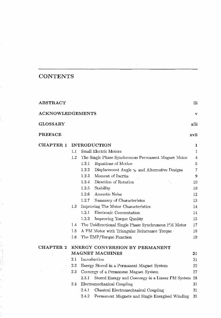
Figure 1.1 Single phase synchronous permanent magnet motor. Single slot or U shape stator design (reproduced from Fig. 1 of [Bertram and Schemmann 1976]).
the rotor is dis-aligned from the direct axis or d-axis of the stator, at a startable rotor
position shown by displacement angle 'Yr.
The high coercivities of modern ceramic PM materials have made the practical ap
plication of this type of motor possible [Bertram and Schemmann 1976, Veinott 1987].
According to [Altenbernd and Wahner 1996], the use of this motor has become increas
ingly more common since the paper on these motors by [Thees 1965]. The experimental
motors demonstrated by Thees had a maximum power output of Pout = 4.5 W, and
an input power of Pin = 9 W. This power rating limited the commercial usage to
applications such as electric can openers, juicers, and aquarium pumps. Since then
the power rating has increased for use in higher power applications. [Altenbernd and
Wahner 1996] note that since the mid 1980's, this type of motor has been taking the
place of shaded pole motors, particularly as a washing machine pump motor with a
rating of 15-30 W. This trend is continuing to strengthen.
This synchronous motor has the attraction of being as simple and robust as the
shaded pole motor. Efficiency higher than 50% is obtained due to the PM excitation
eliminating rotor J2 R loss [Altenbernd and Mayer 1990]. Power output per unit volume
is also high [Bertram and Schemmann 1976]. However, due to its starting and stability
characteristics, it is suitable only for certain applications. These characteristics are
described in the following sections.
1.2.1 Equations of Motion
[Schemmann 1971, Schemmann 1973] presents a theoretical model for the single phase
synchronous PM motor. In his model, Schemmann assumes that the PM flux and the
PM reluctance torque vary sinusoidally with respect to the rotor position. The PM
6 CHAPTER 1 INTRODUCTION
flux linking the stator coils is given by
A.m = - >-m cos e (1.4)
where
>-m amplitude of the PM flux linkage (flux-turns)
e rotor angle
A theoretical analysis in section 4.7 shows that the assumption of a sinusoidal PM
flux linkage for a 2-pole motor is a very good approximation. This is confirmed by
the experimental results of section 5.5.3. Schemmann's electrical equation of motion,
which enables the electrical behaviour of the motor to be modelled, is given by
(1.5)
where
R stator winding resistance
L stator winding inductance
B de /dt
The motor terminal voltage is equal to the AC supply voltage:
v = {j sin(wet + E) (1.6)
where
{j the amplitude of the AC supply voltage
We electrical angular speed
E phase angle of the supply voltage
According to d' Alemberts law, the sum of the torques acting on the rotor is zero. The
mechanical equation of motion describing the mechanical behaviour of the motor is
given by
JdB rn _., . e _ dW(i=O) dt +.L/ - VIm sm de (1. 7)
where
J moment of inertia of the rotor and load
Tl load and friction torque
W stored magnetic energy
The second RHS term is the derivative of the stored magnetic energy set up by the
PM as a function of rotor position, and yields the PM reluctance torque. The stored
energy of a PM system is defined in section 2.2. The PM reluctance torque is given by
dW(i=O) A.
Tr = - de = -Tr sm[2(e-'Yr)] (1.8)
1.2 THE SINGLE PHASE SYNCHRONOUS PERMANENT MAGNET MOTOR 7
where
'ir = amplitude of the PM reluctance torque
'"Yr PM reluctance torque displacement angle
The inductance is not assumed to vary with either rotor angle or current. Schemmann
shows that simulation results using these equations match sufficiently well the measured
performance of the motor.
1.2.2 Displacement Angle '"Yr and Alternative Designs
From eqn.s 1.7 and 1.8, the acceleration torque is given by
(1.9)
When the rotor and stator poles are aligned together at angles of e = 0° or e = 180°,
the mutual phase-magnet torque described by the first RHS term is zero. Near the
vicinity of these angles this phase-magnet torque is also small. The PM reluctance
torque performs the function of moving the rotor to the start able and stable detent
position at e = '"Yr after switch-off. After switch-off, as the rotor slows down to come
to rest, the PM reluctance torque must be greater than the friction torque to enable
the rotor to move away from the aligned position at e = 0 to e = '"Yr. Therefore a limit
is placed on the magnitude of the friction torque such that at e = 0:
'ir sin(2'"Yr) > Tfriction (1.10)
This limit can be increased by increasing '"Yr up to a value of 45°, and by increasing 'ir .
Prior to starting, the rotor position is e = '"Yr. At start the stator winding is
energised, and the starting torque is given by i~m sin '"Yr. This torque must be greater
than the static friction torque for the rotor to move. Therefore, a limit is placed on
the static friction torque such that
i~m sin '"Yr > Tstatic friction (1.11)
These equations demonstrate that the initial starting torque available is dependent on
the size of the displacement angle '"Yr.
The size of the displacement angle depends on the stator shape, and the size of the
rotor diameter in relation to the diameter of the stator airgap. For the single slot design
of Fig. 1.1, the displacement angle is typically limited to 5 - 12° [Altenbernd 1991].
Therefore, the initial starting torque available is not large. Other stator designs are
possible which may extend the displacement angle. The stator of a shaded pole induc
tion motor can be used without the shading coil, as shown by Fig. 1.2(a). The slit in
the stator affects the PM reluctance, but the displacement angle is still small.
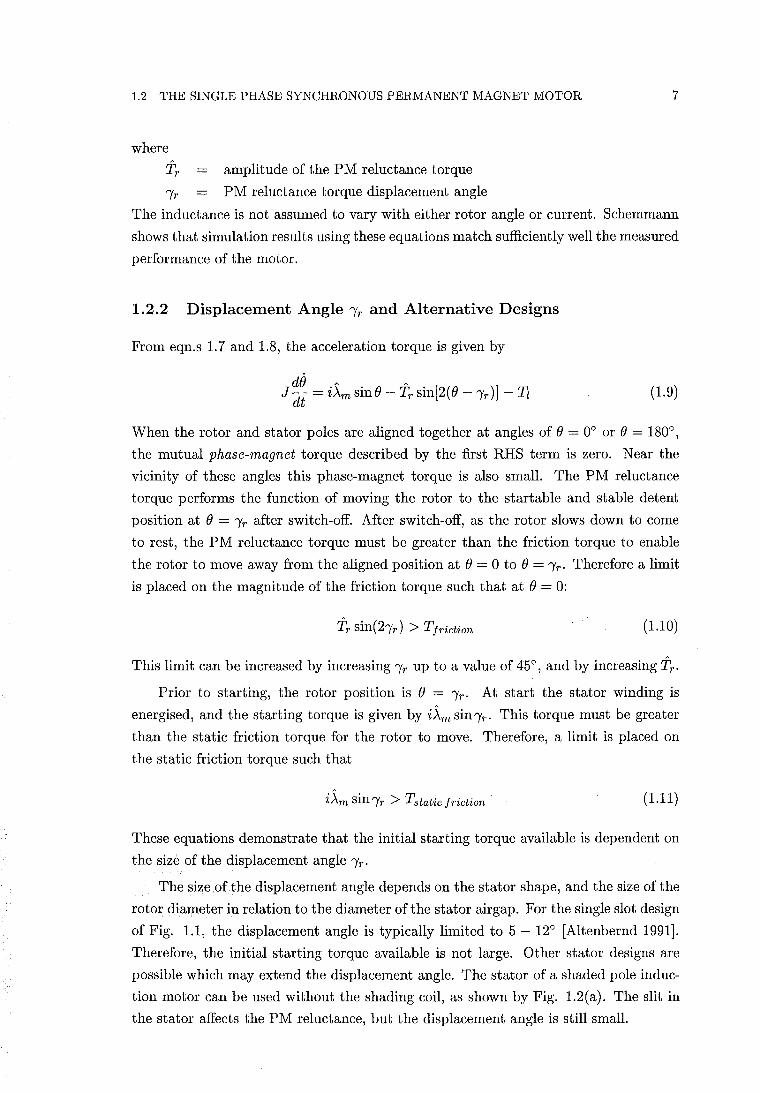
8 CHAPTER 1 INTRODUCTION
q-oxis
(a) Shaded pole stator. (b) Motor with "Yr = 90° .
(c) Isolated pole.
Figure 1.2 Single phase synchronous PM motor designs (reproduced from [Altenbernd 1991]). (b) and (c) are described by European patents EP 0 358 805 A1 and EP 0 358 806 A1, respectively.
The design shown in Fig. 1.2 (b) allows a displacement angle of 90°, enabling
the largest possible starting torque. With the stator de-energised, the widened stator
airgaps along the drawn d-axis cause the PM rotor to align with the q-axis where the
PM reluctance is minimised. The rotor is shown aligned at this minimum reluctance
position of (J = 'Yr = 90° in Fig. 1.2(b). During running, when the PM rotor N-S
poles are instantaneously aligned with the d-axis at (J = 0, the reduced pole widths
along the q-axis saturate. This is due to both the PM flux and the stator current.
This saturation prevents a short circuit of PM flux. A disadvantage of this closed slot
design is that leakage reduces the PM flux linking the stator coils by typically 25%.
The PM reluctance torque is zero at the unstable detent positions of 0° and 180°. The
amplitude of the PM reluctance torque Tr is limited to 5 - 10% of the rated load in
order for the motor to run smoothly [Altenbernd 1991]. Given the angles of the unstable
zero reluctance torque positions (aligned with the d-axis), and the limited value of Tr ,
this design may be expected to be particularly sensitive to frictional torque adversely
effecting the ability of the rotor to come to rest at a startable position.
Fig. 1.2(c) shows another stator design which creates a displacement angle by
increasing saturation in the stator laminations. The displacement angle in this design
cannot be extended to 90°.
1.2 THE SINGLE PHASE SYNCHRONOUS PERMANENT MAGNET MOTOR 9
Multiple pole pair versions of the single phase synchronous PM motor are also
manufactured, and have very low power outputs, but high torque. These motors employ
a single circular stator winding and claw poles to obtain a stator with a high number
of poles. For example, a motor manufactured by Crouzet, France, uses a circular
winding. The steel casing of this motor is used as the stator yoke. Claw poles extend
from each end of the casing to the cavity within the inner diameter of the coil, creating
alternating Nand S poles at the inner circumference when the coil is energised. A
radially magnetised ferrite rotor having the same number of poles is placed in the
space inside the coil and stator poles. A displacement angle is obtained by making the
lengths of portions of selected stator pole claws shorter. The motor has 10 poles, and
is rated at 220 V, 50 Hz, and has a shaft speed of 600 RPM. [Gieras and Wing 1997, p.
235] describe two other multiple pole pair designs which also use a circular winding and
claw poles. Multiple pole pair motors are used as timing motors in automatic control
systems, electric clocks, movie projectors, and impulse counters, etc. Unlike the 2-pole
designs, the primary role of these motors is not the delivery of mechanical power.
1.2.3 Moment of Inertia
When the stator is energised, the stator field changes polarity every half electrical
cycle. During starting, the rotor accelerates. For unidirectional motion to be continued
through the next half cycle, the rotor is required to have rotated a half cycle. This
requires the rotor to reach synchronous speed within a half cycle. Synchronous speed
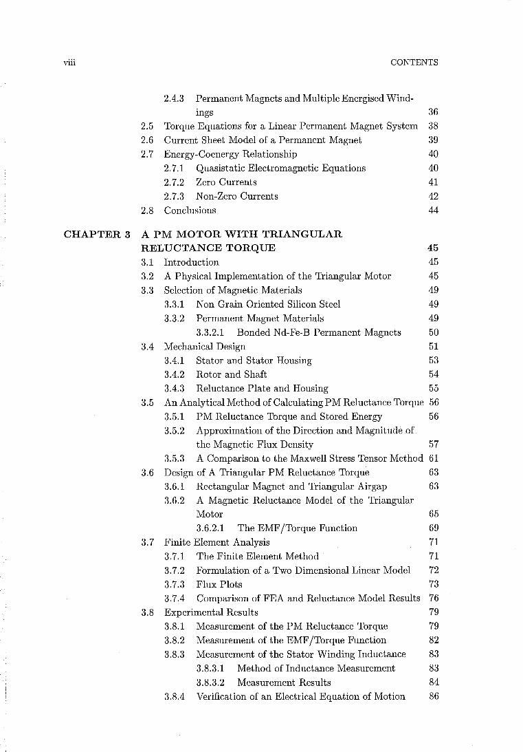
must therefore be reached within 10 ms using a 50 Hz supply. Figure 1.3 shows a
t '<
Figure 1.3 Typical starting characteristic. T = starting time. (reproduced from Fig. 2 of [Bertram and Schemmann 1976]).
typical starting characteristic for this type of motor. In this example, the rotor behaves
erratically and reverses direction several times before accelerating to synchronous speed
over a very short interval. [Bertram and Schemmann 1976] note that this synchronising
step takes less than 6 ms and that the acceleration over this interval is constant. The
10
required acceleration is then
.. We Omin =
T
CHAPTER 1 INTRODUCTION
(1.12)
where B = de / dt, and T is the starting time required to accelerate from standstill to
synchronous speed as shown in Fig. 1.3. The possible acceleration is obtained from
equation 1.9. It is found that the synchronising acceleration takes place at an angle
where i~m sin 0 is large. This occurs at about 0 = 90° or 0 = 270°. The PM reluctance
torque and the load torque can be considered to be less significant in comparison to the
phase-magnet torque i~m sinO. By neglecting these smaller terms, and by expressing
the current in terms of the peak locked rotor current v / Z, the maximum possible
acceleration is approximated as
(1.13)
where
(1.14)
Setting Bmax > Bmin enables an upper limit for the moment of inertia J to be found.
This upper limit is very low and places a severe restriction on the applications suitable
for this type of motor. For a pump application, a highly elastic rubber impeller blade
has been used which bends during starting to reduce the effect of the moment of
inertia of the liquid surrounding the impeller blade [Bertram and Schemmalln 1976].
The limit to the moment of inertia establishes an upper limit on the size and power
rating of these motors, because the rotor inertia is proportional to the fourth power of
the rotor diameter.
1.2.4 Direction of Rotation
The final direction of rotation is not predetermined. The final direction depends on the
initial values of the system of equations 1.5 and 1.7. This limitation further restricts
suitable applications, or requires a mechanical direction correcting device to ensure
unidirectional motion.
1.2.5 Stability
[Schemmann 1971, Schemmann 1973] has shown that this type of motor has useful
motion only within a limited range of motor parameters. Table 1.1 presents plots of the
motions of a motor for various supply voltages, compiled by Schemmann. Useful motion
occurs when the motion is unperturbed, as shown by examples 6 and 8. The unperturbed
motion has a twice electrical frequency speed modulation. Other periodic motions are
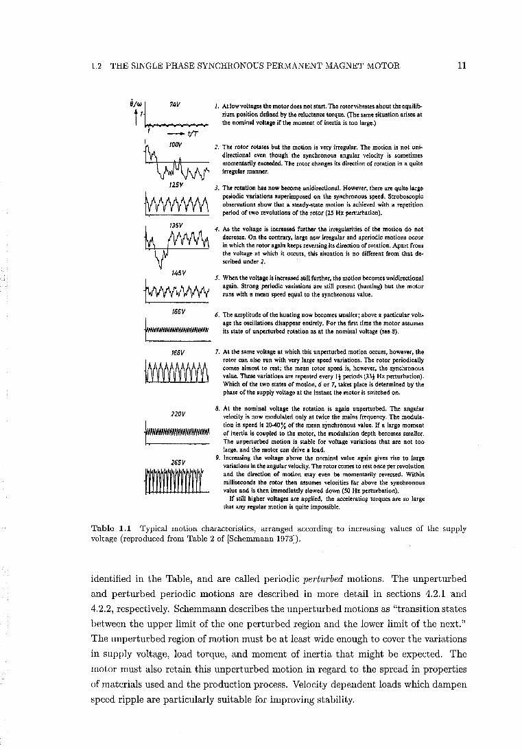
1.2 THE SINGLE PHASE SYNCHRONOUS PERMANENT MAGNET MOTOR
-tIT
~ 125V
~
~ 145 V
~ 166 V
166V
22DV
265 V
III{
1. At low voltages the motor does not start. The rotor vibrates about the equilibrium position defined by the reluctance torque. (The same situation arises at the nominal voltage if the moment of inertia is too large.)
2. The rotor rotates but the motion is very irregular. The motion is not unidirectional even though the synchronous angular velocity is sometimes momentarily exceeded. The rotor changes its direction of rotation in a quite irregular manner.
3. The rotation hal now become unidirectional. However, there are quite laige peJiodic variations superimposed on the synchronous speed. Stroboscopic observations show that a steady-state motion is achieved with a repetition period of two revolutions of the rotor (25 Hz perturbation).
4. As the voltage is increased further the irregularities of the motion do not decrease. On the contrary, large new irregular and aperiodic motions occur in which the rotor again keeps reversing it. direction of rotation. Apart from the voltage at which it occurs, this situation is no different from that described under 2.
S. When the voltage is increased still further, the motion becomes unidirectional again. Strong periodic variations arc still present (hunting) but the motor runs with a mean speed equal to the synchronous value.
6. The amplitUde of the hunting now becomes smaller; above a particular voltage the oscillations disappear entirely. For the first time the motor assumes its state of unperturbed rotation as at the nominal voltage (see 8).
7. At the same voltage at which this unperturbed motion occurs, however, the rotor can also run with very large speed variations. The rotor periodically comes almost to rest; the mean rotor speed is, howe"er, the synchronous value. These variations arc repealed every It periods (33t Hz perturbation). Which of the two states of motion, 6 or 7, takes place is determined by the phase of the supply voltage at the instant the motor is switched on.
8. At the nominal voltage the rotation is again unperturbed. The angular velocity is now modulated only at twice the mains frequency. The modulation in speed is 2().4()% of the mean synchronous value. If a large moment of inertia is coupled to the motor, the modulation depth becomes smaller. The unperturbed motion is stable for voltage variations that are not too large, and the motor can drive a load.
9. Increasing the voltage above the nominal value again gives rise to large variations in the angular velocity. The rotor comes to rest once per revolution and the direction of motion may eveD be momentarily reversed. Within milliseconds the rotor then assumes velocities far above the synchronous value and is then immediately slowed down (SO Hz perturbation).
If still higher voltages are applied, the accelerating torques are so large that any regular motion is quite impossible.
11
Table 1.1 Typical motion characteristics, arranged according to increasing values of the supply voltage (reproduced from Table 2 of [Schemmann 1973]).
identified in the Table, and are called periodic perturbed motions. The unperturbed
and perturbed periodic motions are described in more detail in sections 4.2.1 and
4.2.2, respectively. Schemmann describes the unperturbed motions as "transition states
between the upper limit of the one perturbed region and the lower limit of the next."
The unperturbed region of motion must be at least wide enough to cover the variations
in supply voltage, load torque, and moment of inertia that might be expected. The
motor must also retain this unperturbed motion in regard to the spread in properties
of materials used and the production process. Velocity dependent loads which dampen
speed ripple are particularly suitable for improving stability.
12 CHAPTER 1 INTRODUCTION
Because of the development work required, the motor is only really suitable for
mass production techniques [Schemmann 1973]. [Diefenbach and Schemmann 1989]
describe the motor design process for a shaver application. This description highlights
the difficulty that can be involved in the designing of a stable motor.
1.2.6 Acoustic Noise
The modulation in the speed is the result of the pulsating torque caused by the back
ward rotating field of the single phase winding. For an electrical supply frequency of
50 Hz, the unperturbed speed modulation acts as a source of 100 Hz oscillation. This
can lead to problems of acoustic noise, particularly for water-pumping applications
[Altenbernd and Wahner 1996]. For the U-shape stator design of Fig. 1.1, the stator
laminations act as tuning forks, leading to 1200-1800 Hz resonant harmonic oscillations.
[Altenbernd and Wahner 1996] comment that the noise resulting from these oscillations
hampers their use in high quality household appliances. It is possible to tune the res
onant frequency of the stator yoke to less subjectively annoying frequencies, but the
fundamental harmonic remains.
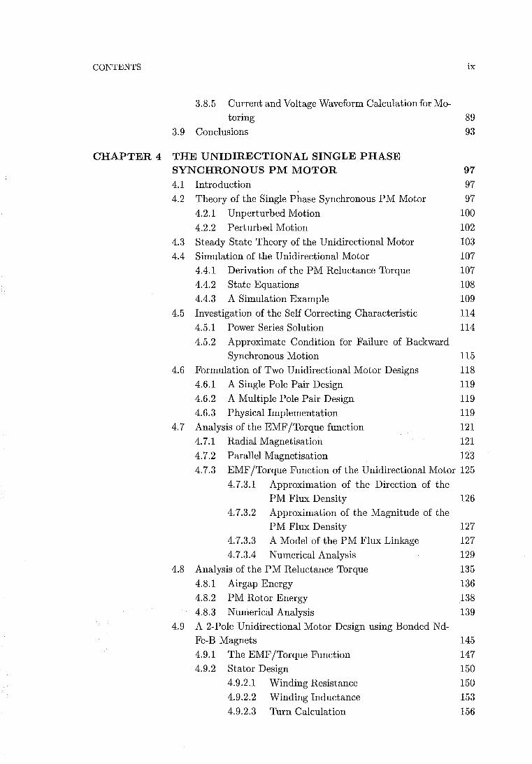
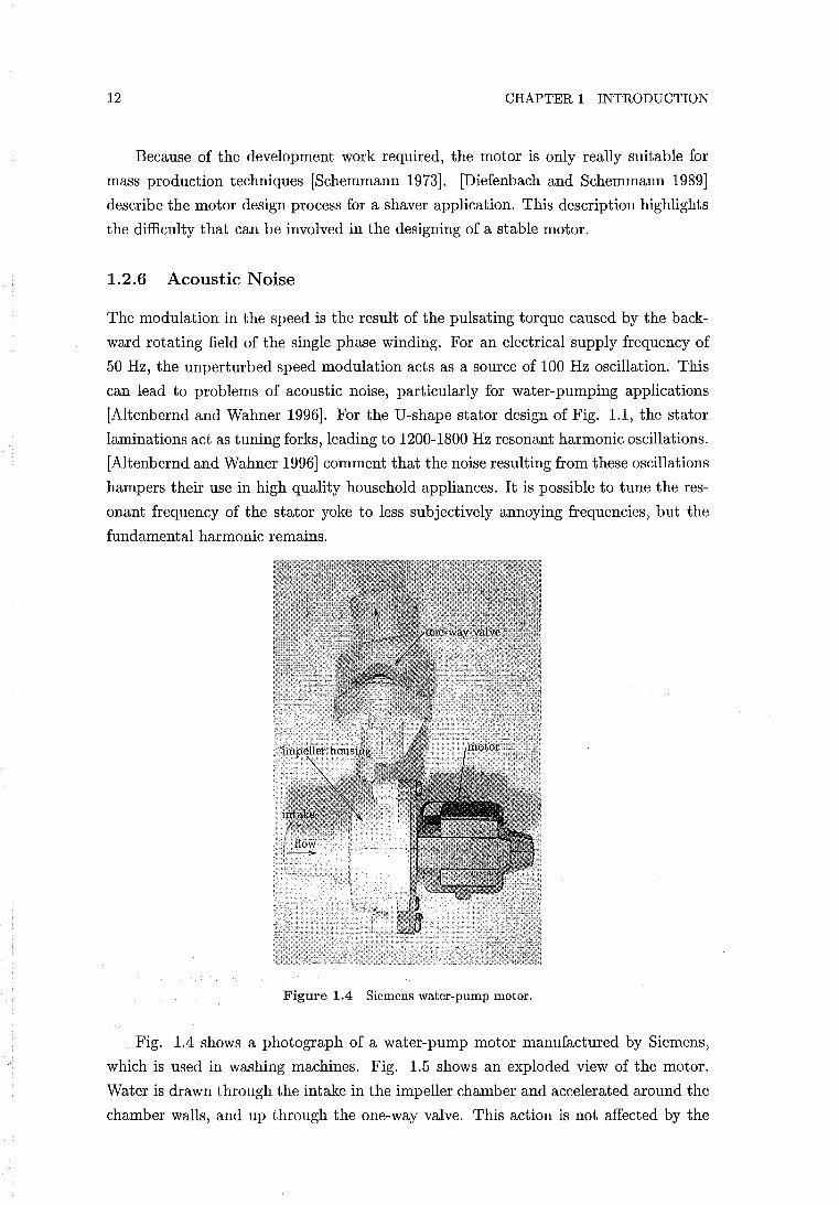
Figure 1.4 Siemens water-pump motor.
Fig. 1.4 shows a photograph of a water-pump motor manufactured by Siemens,
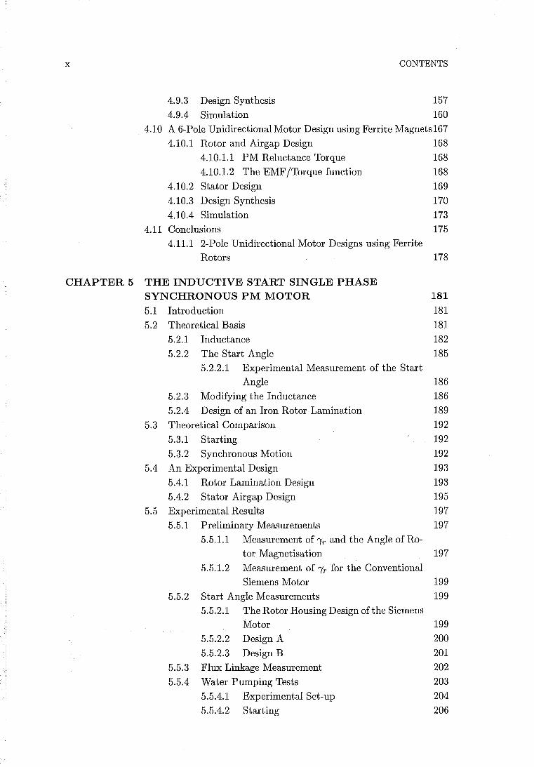
which is used in washing machines. Fig. 1.5 shows an exploded view of the motor.
Water is drawn through the intake in the impeller chamber and accelerated around the
chamber walls, and up through the one-way valve. This action is not affected by the
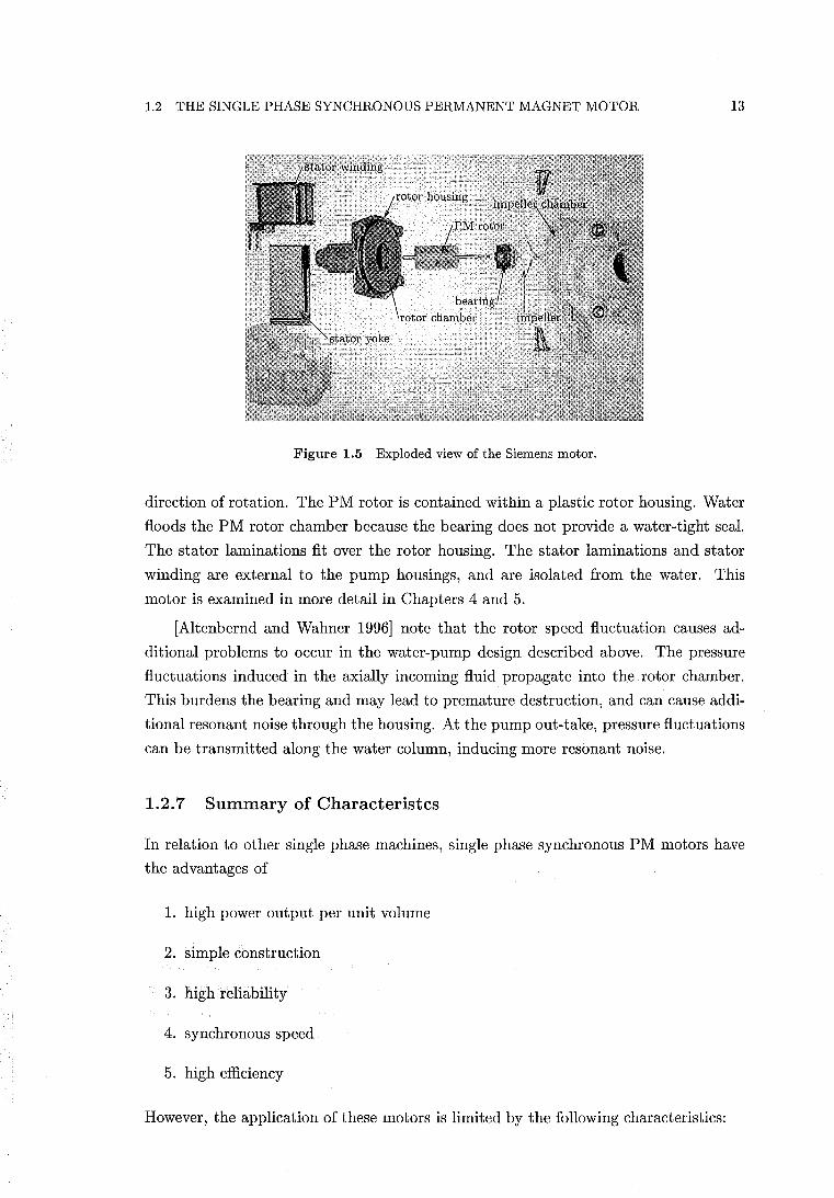
1.2 THE SINGLE PHASE SYNCHRONOUS PERMANENT MAGNET MOTOR 13
Figure 1.5 Exploded view of the Siemens motor.
direction of rotation. The PM rotor is contained within a plastic rotor housing. Water
floods the PM rotor chamber because the bearing does not provide a water-tight seal.
The stator laminations fit over the rotor housing. The stator laminations and stator
winding are external to the pump housings, and are isolated from the water. This
motor is examined in more detail in Chapters 4 and 5.
[Altenbernd and Wahner 1996] note that the rotor speed fluctuation causes ad
ditional problems to occur in the water-pump design described above. The pressure
fluctuations induced in the axially incoming fluid propagate into the rotor chamber.
This burdens the bearing and may lead to premature destruction, and can cause addi
tional resonant noise through the housing. At the pump out-take, pressure fluctuations
can be transmitted along the water column, inducing more resonant noise.
1.2.7 Summary of Characteristcs
In relation to other single phase machines, single phase synchronous PM motors have
the advantages of
1. high power output per unit volume
2. simple construction
3. high reliability
4. synchronous speed
5. high efficiency
However, the application of these motors is limited by the following characteristics:
14 CHAPTER 1 INTRODUCTION
1. The moments of rotor and load inertia must be low enough to allow synchroni
sation. This places a limit on the rotor diameter, and the power rating.
2. There is no control over the final direction of rotation, unless a mechanical cor
recting device is used.
3. Frictional torque must be low enough such that the rotor can come to rest at a
startable position. The displacement angle 'Yr is, in general, limited.
4. It can be difficult to design a stable motor. Loads with velocity dependent damp
ening are most suitable.
5. The twice electrical frequency speed modulation can cause noise problems.
1.3 IMPROVING THE MOTOR CHARACTERISTICS
In this section, possible methods of improving the characteristics of the single phase
PM motor are examined.
1.3.1 Electronic Commutation
If a single phase synchronous PM motor is not connected directly to an AC supply,
and instead electronically commutated, a motor of the form described by [Mayer and
Wasynezuk 1989] or [Hendershot and Miller 1994, p.3.4] can be obtained. These
motors use a bifilar winding, a DC to AC inverter requiring two transistors, and a Hall
effect sensor to determine rotor position. Logic circuitry is also required to convert the
Hall sensor information into appropriate switching signals for the transistors. These
motors are known as single phase bifilar wound DC motors. They may have multiple
pole pairs, and have an exterior PM rotor. Because they only require a few electronic
components, these motors are cost-effective in light duty fan applications [Hendershot
and Miller 1994].
[Altenbernd and Wahner 1996] propose the use of simple AC circuitry to extend
the power range of the directly connected 2-pole motor. The power output limit for the
directly connected 2-pole motor is 50-60 W. This is achieved by extending the length of
the rotor, rather than its diameter. The rotor length to diameter ratio is about 3-4, and
is difficult to extend further due to the problem of transverse oscillations [Altenbernd
and Wahner 1996]. To extend the power range, a triac is placed in series with the motor
and the AC supply. A Hall sensor is required, and circuitry monitors the phase of the
supply voltage. The current may also be monitored. This scheme removes the inertial
constraint for start-up, and improves stability. The power output can be extended to
200 W.
1.3 IMPROVING THE MOTOR CHARACTERISTICS 15
Electronic control alleviates most of the limiting characteristics, that apply to the
direct connected motor, listed in section 1.2.7. With electronic control, there is no
inertia limitation, the direction of rotation is determined, stability is improved by the
use of the Hall sensor to ensure synchronism, and the inertia is generally higher so
speed ripple can be better damped. The requirement that the motor must come to rest
at a startable position still remains a limitation. On the negative side, the complexity
increases due to the electronics, increasing cost and decreasing reliability.
1.3.2 Improving Torque Quality
The other way of improving characteristics is to improve motor design. Both the
directly connected and electronically commutated motors described so far have large
pulsating torques. The torque pulsates at twice the electrical frequency, dipping to
zero or to a negative value every half cycle. An examination of ways to improve the
torque quality of a single phase PM motor is a possible starting point for improving
characteristics. If the motor torque can be made constant with respect to rotor position,
speed ripple and noise problems are eliminated. This also implies that a starting
torque is available at all rotor positions. Limiting characteristics 3 and 5, of section
1.2.7, are thereby eliminated. The challenge is to create a constant instantaneous
torque using only a single winding. This may be achieved if the two motor torque
components, the phase-magnet torque, and the PM reluctance torque, add to equal a
constant instantaneous value. The load torque is set equal to the sum of these motor
torques, and the acceleration is zero. For a motor which can be modelled adequately by
approximating sinusoidal phase-magnet coupling and sinusoidal PM reluctance torque,
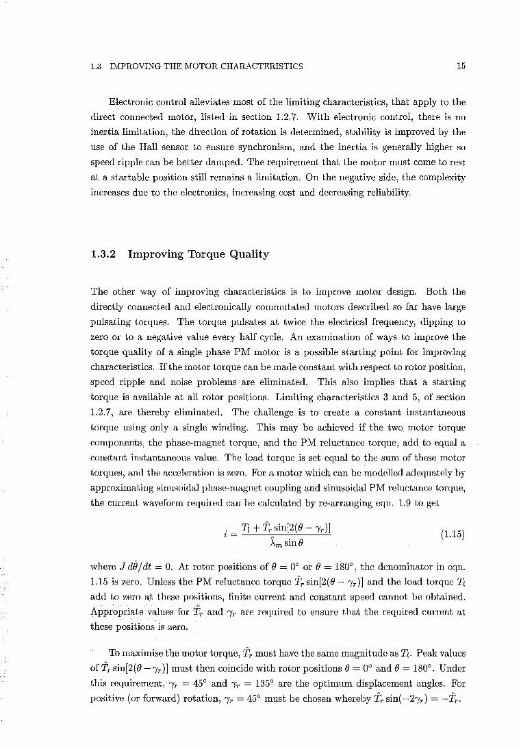
the current waveform required can be calculated by re-arranging eqn. 1.9 to get
. Tz + 'ir sin[2(O -,r)] ~ - ----:--=--.:_--'--'-'-
- ~m sinO (1.15)
where J de / dt = O. At rotor positions of 0 = 0° or 0 = 180°, the denominator in eqn.
1.15 is zero. Unless the PM reluctance torque 'ir sin[2(O -Ir)] and the load torque Tz
add to zero at these positions, finite current and constant speed cannot be obtained.
Appropriate values for 'ir and Ir are required to ensure that the required current at
these positions is zero.
To maximise the motor torque, 'ir must have the same magnitude as Tz. Peak values
of'ir sin[2(O -,r)] must then coincide with rotor positions 0 = 0° and 0 = 180°. Under
this requirement, Ir = 45° and Ir = 135° are the optimum displacement angles. For
positive (or forward) rotation, Ir = 45° must be chosen whereby 'ir sin( -2,r ) = -'ir'
16 CHAPTER 1 INTRODUCTION
phase-magnet torque, Tph-m = i>-m sin ()
\ rotor angle (elect deg) PM reluctance torque, Tr
°l~'~ EMF/torque function, d2; =>-m sin(}?
reactive voltage, Lft
terminal voltage, v
.... _------v
Figure 1.6 Unidirectional single phase synchronous PM motor waveforms.
For forward rotation with IT = 45° and Tl = 'iT' eqn. 1.15 becomes
(1.16)
and demonstrates that a constant instantaneous torque can be achieved with a sinu
soidal current. Fig. 1.6 shows the torque and current waveforms over an electrical
cycle. Under these conditions, the PM reluctance torque cancels out the pulsations in
the phase-magnet torque Sm sinO, and effectively acts as a second balancing phase.
The load and rated torques are set equal to the amplitude of the PM reluctance torque,
'iT'
The ability to rotate to a startable rest position is greatly enhanced in relation
to the conventional designs. With IT = 45°, eqn. 1.10 shows that the reluctance
torque available to move the motor away from the unstartable rotor position of () = 0
is maximised. In addition, because the amplitude of the reluctance torque is set equal
to the rated load, it is relatively large. Once the rotor has come to rest at the stable
detent position of 0 = IT = 45°, the starting torque available later when the stator is
energised is also high. Eqn. 1.11 shows that 70% of the maximum starting torque is
available with IT = 45°.
1.4 THE UNIDIRECTIONAL SINGLE PHASE SYNCHRONOUS PM MOTOR 17
With reference to eqn. 1.5, the terminal voltage, with the current determined by
eqn. 1.16, is
v L di/dt + iR + iJ~m sin(J
-A- cos(J + -A- + (JAm smB 2LTriJ [2RTr. A 1 . Am Am
(1.17)
The acceleration is zero and iJ is equal to the synchronous speed We' Therefore this is
a sinusoidal voltage equal to v = {) sin(wet + E). {) and E are respectively given by
(1.18)
(1.19)
In eqn. 1.18, the amplitude of the current i is 2Tr / ~m' and the amplitude of the EMF,
e, is given by we~m. e and i are in phase. e and i lag the peak inductive voltage
2weLTr / ~m by 900• Both e and i lag {) by phase angle E. The electrical waveforms are
also shown in Fig. 1.6, and a phaser diagram is shown by Fig. 4.1(b). The constant
instantaneous torque concept described here provides the basis for two proposed single
phase PM motors, which are described in the following sections.
1.4 THE UNIDIRECTIONAL SINGLE PHASE SYNCHRONOUS PM MOTOR
The first of these motors employs the sinusoidal waveforms described in section 1.3.2.
This motor is directly connected to a single phase AC supply, and is a special case of
the conventional PM motor described in section 1.2. Chapter 4 examines this proposed
motor in detail and describes a physical implementation. It is shown that this motor
has the capability to start, and to produce a smooth torque under rated load. It is also
shown to be unidirectional, if designed appropriately. The term unidirectional is used
here to describe motional behaviour in which, after a brief starting transient, the motor
only runs in the forward direction. No mechanical correcting device is necessary. This
motor will be referred to as the unidirectional single phase synchronous PM motor, or
the unidirectional motor for short. These aspects of operation are demonstrated by
computer simulation using the simulation equations developed by [Schemmann 1971].
The unidirectional motor has the simplicity of its conventional counterpart, and is
also intended for domestic application. The constant instantaneous torque concept is
thus shown to eliminate limiting characteristic number 2, as well as numbers 3 and 5,
18 CHAPTER 1 INTRODUCTION
described in section 1.2.7, for a directly connected motor. However, it is shown that the
unidirectional motor requires an even tighter inertial constraint than the conventional
motor.
1.5 A PM MOTOR WITH TRIANGULAR RELUCTANCE TORQUE
phase-magnet torque, Tph-m = i~
270
\ rotor angle (elect deg) PM reluctance torque, Tr
O~~-+----+----+--~~---++---+----+--~
EMF !torque function, ~
/reactive voltage, Lft
0~~~~±=~~==T=~~
jterminal voltage
Vdc +-_-_-_-j-'-_-_-___ -'+ _____ 1 ~:Ck EMF
0+----+----+----+----+----+----+----+----+
--------f--------
Figure 1. 7 Triangular motor waveforms.
It is also possible to implement the constant instantaneous torque concept using
non-sinusoidal waveforms. The idealised waveforms of an alternative such implemen
tation are shown in Fig. 1.7. The PM reluctance torque and the phase-magnet torque
again add together to provide a constant motor torque. The PM reluctance torque
waveform is triangular and completes two cycles per electrical cycle. The current
waveform is also triangular, and the motor will be referred to as the triangular mo
tor in virtue of these waveform shapes. The back EMF is a square-wave, however a
trapezoidal waveform can only be achieved in practice. The inductance ideally remains
constant and the armature voltage given by Ldi/dt is a square-wave. The terminal
voltage is ideally a square-wave, but has two steps per half cycle. The heights of the
steps depend on the magnitude of the inductance. The voltage drop across the winding
resistance has been neglected in Fig. 1.7.
1.6 THE EMF/TORQUE FUNCTION 19
The required terminal voltage is non-sinusoidal, therefore the triangular motor is
unsuitable for direct connection to an AC supply. A DC to AC inverter and Hall
sensors are required to drive the motor. Including electronic control allows all the
limiting characteristics described in section 1.2.7 to be eliminated. It is also possible to
electronically control the unidirectional motor, but the triangular motor may be more
suitable for connection to a DC to AC inverter because its required terminal voltage
is closer in shape to a squarewave. A triangular motor has been built to demonstrate
that the required non-sinusoidal characteristics can be implemented. This is described
in Chapter 3.
1.6 THE EMF/TORQUE FUNCTION
The purpose of this section is to define a quantity which is used throughout the thesis.
This quantity is introduced by first describing the constants used to model brushed DC
motors. The back EMF of a brushed DC motor is given by
(1.20)
where
kE back EMF constant
The air gap torque is given by
T=kTI (1.21 )
where
kT torque constant
I DC current
For the brushed DC motor, kE and kT are equivalent if they are in consistent units
[Hendershot and Miller 1994, p. 7.3]. In this case a single symbol k could be used to
determine both the torque and the EMF, and could be called the EMF/torque constant.
For a single phase motor, the instantaneous EMF induced in the winding due to a
PM is given according to Faraday's law by
where
_ dAm _ dAm e' e - dt - de
dAm/ de = rate of change of the PM flux linkage with respect to
the rotor position
(1.22)
In section 2.5, the torque due to the mutual coupling between the phase and the magnet
20
is obtained from eqn. 2.64 as
fTl • dAm .Lph-m = ~de
CHAPTER 1 INTRODUCTION
(1.23)
A comparison of eqn.s 1.22 and 1.23 shows that dAm/dB, or the rate of change of the
PM flux linkage with respect to the rotor position, is related to both the instanta
neous back EMF and the instantaneous phase-magnet torque for a single phase motor.
Like k for a brushed DC motor, dAm/dB may be defined in consistent units such as
Nm/A (Newton-metres per Ampere) or V.s/rad (Volt-seconds per radian). Unlike a
brushed DC motor where k is essentially constant, dAm/dB may vary as a function of
the rotor position. Given these characteristics, dAm/dB will be called the EMF/torque
function. The EMF/torque function is referred to throughout this thesis, and allows
easy calculation of the EMF or torque, derived from a single unifying quantity.
Chapter 2
ENERGY CONVERSION BY PERMANENT MAGNET MACHINES
2.1 INTRODUCTION
Energy methods are widely used and well understood for determining the torque or force
in magnetically nonlinear or linear machines that do not contain permanent magnets.
Energy methods are employed to calculate torques or forces of magnetic origin after
determination of the energy stored in the electromechanical coupling field. The origins
of this theory date back at least as far as [Maxwell 1891] where the equation for the
force resulting from the "mechanical action between two circuits" in the absence of
magnetic material is expressed in terms of currents and inductance coefficients:
(2.1)
where i1 and i2, L1 and L2 are the respective currents and inductance coefficients of the
two circuits, M, the mutual inductance; Fx , the component of force in the direction
of x. With regard to eqn. 2.1, Maxwell stated that "If the motion of the system
corresponding to the variation of x is such that each circuit moves as a rigid body, L1
and L2 will be independent of x and the equation will be reduced to the form,"
In the case of a single circuit, eqn. 2.1 reduces to
F _ ~'2dL1 x - 2~ dx
(2.2)
(2.3)
Eqn. 2.1 was later shown to also hold for circuits which do enclose, or are near iron,
provided there is no saturation. Thus Maxwell's equation included the solutions of
the cases of one or two circuits involving inductances which are not functions of the
current.
Iron saturation in a single circuit electromagnet was considered by [Steinmetz 1911].
22 CHAPTER 2 ENERGY CONVERSION BY PERMANENT MAGNET MACHINES
The scope of this work was to express the energy relations which occur during a change
in position. This constituted the initial step toward the derivation of a general equation
for the force of a single circuit, where iron saturation may be present.
The contributions of Maxwell and Steinmetz, amongst others, provide a back
ground of earlier work, as described by [Doherty and Park 1926], for their paper. The
scope of the theory was extended by [Doherty and Park 1926] by applying the prin
ciple of conservation of energy to provide general equations for an arbitrary number
of circuits which may contain iron, either saturated or not, but are assumed to have
no hysteresis or residual magnetism. This has been followed by comprehensive treat
ments of electromechanical coupling theory by [White and Woodson 1959], [Fitzgerald
et al. 1983]' and [Woodson and Melcher 1968].
The increasing use and improving technology of permanent magnet materials has
generated a need to incorporate materials exhibiting residual magnetism into this the
ory. However, the application of energy methods to permanent magnet systems has
appeared to be based on plausible assumptions rather than logical derivation. The
purpose of this chapter is to show how the classical theory can accommodate resid
ual magnetism. By addressing the magnetisation process it shows how stored energy
may be defined in a permanent magnet system. By then examining energy methods,
a solid theoretical base for a selection of torque equations 1 used by both machine and
CAD system designers, as well as some less obvious equations, is provided. In CAD
(computer aided design) systems, energy methods, followed by the Maxwell stress ten
sor method, are the most common approaches used to calculate torques [Lowther and
Silvester 1986]. Here energy minimising finite element· numerical methods are most
popularly applied. It is therefore essential that the energy methods are also correctly
understood when permanent magnets are present.
2.2 ENERGY STORED IN A PERMANENT MAGNET SYSTEM
In classical electromechanical coupling theory stored energy is a physical quantity which
can be measured experimentally. The stored energy is the energy which can be trans
ferred to or from a conservative electromechanical coupling field via mechanical or elec
trical terminals. In this section the definition of stored energy extended to a system
exhibiting significant residual magnetism or permanent magnetism remains essentially
the same. The specification of a conservative electromechanical coupling field thus
excludes hysteresis from the calculation of torque.
Fig. 2.1 shows a representation of a permanent magnet system consisting of a
winding and a hard magnetic material. The winding has a flux linkage A and current
i and its terminals are depicted in Fig. 2.1. An airgap or linear region and a soft
lIn this chapter, equations for force may be obtained from torque equations by replacing the rotational displacements with linear displacements.

2.2 ENERGY STORED IN A PERMANENT MAGNET SYSTEM
i~ + 0------'------1
electrical 1 . I A,e
termma
A=A (i)
system consisting of - a winding - hard magnetic material - soft magnetic material - airgap region and\or linear material
Figure 2.1 Electrical terminal pair representation of a permanent magnet system.
23
magnetic material may also be included in the system. The soft magnetic material is
modelled as being anhysteretic with the B-H characteristic passing through the origin.
Energy may be transferred to the system electrically or mechanically. To simplify the
calculation of energy transferred to the system, the energy transferred to the system
is accounted for electrically. This is achieved by treating the hard magnetic material
as being initially un-magnetised such that initially A = 0 when i = 0 and any forces
or torques of magnetic origin are zero. All frictional and resistive losses excluding
hysteresis loss are modelled externally to the system. The system may therefore be
non-conservative during the magnetisation process. The system is first mechanically
assembled with A held at zero and the mechanical energy transferred to the system is
zero. The flux linkage is then raised from zero and a voltage e = dA/ dt is induced across
the electrical terminals by the magnetic field. The energy transferred is obtained, in
this case, by the classical equation for stored energy in a singly excited system:
(2.4)
The energy transferred is absorbed as energy which is recoverable (either mechanically
or electrically) and also as energy which is not recoverable. However, eqn. 2.4 and
the A - i characteristic do not, in general, provide sufficient information to allow the
components of recoverable and non-recoverable energy to be determined. Eqn. 2.4 is
equivalently expressed in terms of the energy density of the magnetic field corresponding
to vectors Band H integrated over the volume of the system by
(2.5)
The mathematical transformation from eqn. 2.4 to obtain eqn. 2.5 is described in
[Stratton 1941, pp. 122-124]. This is a transformation from circuit quantities to field
quantities. The field, after commencement of the magnetisation process, may be due
to both currents and residually magnetised material. Eqn. 2.5 allows the energy trans
ferred to the system to be separated using B-H characteristics into components within
elements of the system volume as follows. Fig. 2.2(a) shows a B-H characteristic
for a hard magnetic material. From B = 0 the characteristic follows the initial mag
netisation curve until the saturation flux density Bsat is reached. The energy density
corresponding to energy absorbed by this magnet region is depicted by both shaded
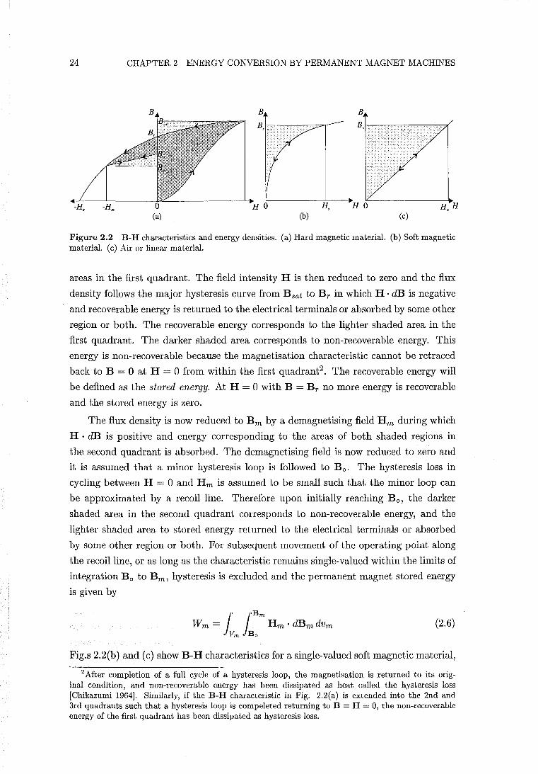
24 CHAPTER 2 ENERGY CONVERSION BY PERMANENT MAGNET MACHINES
B B
H 0 H, (a) (b) (c)
Figure 2.2 B-H characteristics and energy densities. (a) Hard magnetic material. (b) Soft magnetic material. (c) Air or linear material.
areas in the first quadrant. The field intensity H is then reduced to zero and the flux
density follows the major hysteresis curve from Bsat to Br in which H· dB is negative
and recoverable energy is returned to the electrical terminals or absorbed by some other
region or both. The recoverable energy corresponds to the lighter shaded area in the
first quadrant. The darker shaded area corresponds to non-recoverable energy. This
energy is non-recoverable because the magnetisation characteristic cannot be retraced
back to B = 0 at H = 0 from within the first quadrant2 . The recoverable energy will
be defined as the stored energy. At H = 0 with B = Br no more energy is recoverable
and the stored energy is zero.
The flux density is now reduced to Bm by a demagnetising field Hm during which
H . dB is positive and energy corresponding to the areas of both shaded regions in
the second quadrant is absorbed. The demagnetising field is now reduced to zero and
it is assumed that a minor hysteresis loop is followed to Be. The hysteresis loss in
cycling between H = 0 and Hm is assumed to be small such that the minor loop can
be approximated by a recoil line. Therefore upon initially reaching Be, the darker
shaded area in the second quadrant corresponds to non-recoverable energy, and the
lighter shaded area to stored energy returned to the electrical terminals or absorbed
by some other region or both. For subsequent movement of the operating point along
the recoil line, or as long as the characteristic remains single-valued within the limits of
integration Be to B m, hysteresis is excluded and the permanent magnet stored energy
is given by
(2.6)
Fig.s 2.2(b) and (c) show B-H characteristics for a single-valued soft magnetic material,
2 After completion of a full cycle of a hysteresis loop, the magnetisation is returned to its original condition, and non-recoverable energy has been dissipated as heat called the hysteresis loss [Chikazumi 1964]. Similarly, if the B-H characteristic in Fig. 2.2(a) is extended into the 2nd and 3rd quadrants such that a hysteresis loop is compeleted returning to B = H = 0, the non-recoverable energy of the first quadrant has been dissipated as hysteresis loss.
2.2 ENERGY STORED IN A PERMANENT MAGNET SYSTEM 25
and air or linear material, respectively. The areas of the shaded regions correspond to
stored energies. Given that the hard magnetic material has reached a single-valued state
within the limits described above, the electromechanical coupling field is conservative,
and the stored energy of the permanent magnet system is given by
The inner integrals of the three RHS terms of eqn. 2.7 are the energy density functions
of the permanent magnet, soft material, and linear material respectively. Some exam
ples of these energy density functions are given in [Howe and Zhu 1992, Marinescu and
Marinescu 1988], and in section 2.3.1.
An equation is given in [Zijlstra 1982] where the stored energy of the permanent
magnet system is calculated by integrating over only the volume of the magnet. Inte
grating over only the volume of the magnet may be of advantage in some circumstances.
This equation is
(2.8)
By specifying limits of integration, corresponding to second quadrant operating point
(Hm, B m), eqn. 2.8 becomes:
(2.9)
In eqn. 2.9, the permanent magnet stored energy density is given by J:: Hm ·dBm . For
the example of the single-valued recoil characteristic of Fig. 2.2(a), this stored energy
density is represented graphically by the lighter shaded area in the second quadrant.
The rule of differentiation can be applied to any single-valued magnetisation char
acteristic of any quadrant, whereby d(H. B) = H· dB + B . dH. By applying the rule
of differentiation over the second quadrant, and then integrating obtains:
(2.10)
In Fig. 2.2(a), the term - JoHm Bm . dHm is represented by the second quadrant area
which includes the lighter shaded area corresponding to stored energy density, plus the
rectangular area - Bm . Hm lying directly beneath. The term - JoHm Bm . dHm has
a positive value because Bm . dHm is negative over the specified integration limits.
26 CHAPTER 2 ENERGY CONVERSION BY PERMANENT MAGNET MACHINES
Substitution of eqn. 2.10 into eqn. 2.9 yields
(2.11)
Eqn. 2.11 readily identifies an area in the second quadrant of Fig. 2.2(a) which is
bounded by lines connecting the origin, operating point (Hm, B m), and Bo. This area
has been depicted in the literature, and there has been some confusion as to what
it signifies. The first RHS term in eqn. 2.11 is the stored energy in the permanent
magnet material. To obtain the energy of the whole permanent magnet system, the
second RHS term must then represent the stored energy in the regions external to the
permanent magnet. From eqn. 2.73 in section 2.7.2 it can be shown that
(2.12)
if all currents are zero. This shows that the term -~ IVm
Bm . Hm dVm represents the
stored energy of a linear material or airgap external to the permanent magnet if all
currents are zero. As an example, the external region to the magnet may be composed
of linear iron and an airgap. Eqn.s 2.8 and 2.11 are therefore not general and are only
valid if the region outside the permanent magnet is linear and all currents are zero.
Expressions for Band H may be derived as functions of electrical and mechanical
terminal variables. These terminal variables are described in section 2.4.1. Mechanical
displacement is one of these terminal variables. For rotational displacement 0, Band
H may therefore be expressed as B = B(O) and H = H(O). The stored energy given
by Eqn.s 2.7, 2.8, and 2.11 may therefore be expressed as a function of rotational
displacement for the calculation of PM reluctance torque. For a rotational displacement
o with the winding de-energised, or removed, the resulting reluctance torque is defined
as the negative rate of conversion of stored energy into mechanical energy:
T: __ dW(i = 0) r - dO (2.13)
The definition of stored energy given here yields expressions for stored energy which,
when used in eqn. 2.13, are shown to give accurate values of permanent magnet reluc
tance torque [Howe and Zhu 1992, Marinescu and Marinescu 1988].
The definition of stored energy provided here permits determination of the rela
tionship of the mathematical quantity coenergy to stored energy where all currents are
zero, in section 2.3. Energy methods are examined more generally in sections 2.4.2 and
2.4.3 to include torque calculation for non-zero currents.
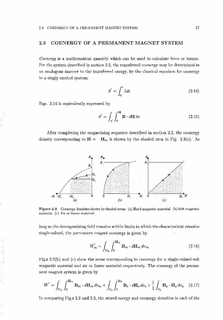
2.3 COENERGY OF A PERMANENT MAGNET SYSTEM 27
2.3 COENERGY OF A PERMANENT MAGNET SYSTEM
Coenergy is a mathematical quantity which can be used to calculate force or torque.
For the system described in section 2.2, the transferred co energy may be determined in
an analogous manner to the transferred energy, by the classical equation for coenergy
in a singly excited system:
(2.14)
Eqn. 2.14 is equivalently expressed by
{J' = Iv foH B . dH dv (2.15)
After completing the magnet ising sequence described in section 2.2, the coenergy
density corresponding to H = -Hm is shown by the shaded area in Fig. 2.3(a). As
B B B
B,f------::='I-- Bal---------,,(
-Hm o o H, H Ha H (a) (b) (c)
Figure 2.3 Co energy densities shown by shaded areas. (a) Hard magnetic material. (b) Soft magnetic material. (c) Air or linear material.
long as the demagnetising field remains within limits in which the characteristic remains
single-valued, the permanent magnet co energy is given by
(2.16)
Fig.s 2.3(b) and (c) show the areas corresponding to co energy for a single-valued soft
magnetic material and air or linear material respectively. The co energy of the perma
nent magnet system is given by
(2.17)
In comparing Fig.s 2.2 and 2.3, the stored energy and coenergy densities in each of the

28 CHAPTER 2 ENERGY CONVERSION BY PERMANENT MAGNET MACHINES
respective materials or regions are related by
J H·dB+ J B·dH=B·H (2.18)
if the magnetisation characteristics are single-valued. Note that eqn. 2.18 holds for
the single-valued recoil characteristic of Fig.s 2.2(a) and 2.3(a), and that the co energy
density of Fig. 2.3(a) is negative.
For a permanent magnet system, with the winding de-energised, eqn. 2.75 III
section 2.7.2 shows that the total stored energy and co energy are related by
w' (i = 0) = -W(i = 0) (2.19)
Substitution of eqn. 2.19 into eqn. 2.13 shows that the reluctance torque is obtained
in terms of co energy by
dW' (i = 0) Tr = de (2.20)
2.3.1 Stored Energy and Coenergy in a Linear PM System
This section demonstrates an example of the energy-co energy relationship in a PM
system where the regions external to the PM have linear magnetisation characteris
tics such as air. The analysis applies to the case where all currents are zero. These
conditions allow the energy stored in the PM system to be calculated by integrating
over only the volume of the magnet using eqn. 2.11. The term -~ IVm Bm . Hm dVm
corresponds to the energy stored in the region external to the PM. Comparison of Fig.s
2.2(c) and 2.3(c) shows that the co energy of the linear region is equal in sign and mag
nitude to the stored energy in that region. The co energy of the PM system may then
be calculated by integrating over only the volume of the magnet by
(2.21)
A PM material is now modelled which will allow eqn.s 2.11 and 2.21 to be evaluated
for a specific example. The demagnetisation characteristic of a PM material may be
modelled by3
(2.22)
where {tr is the relative permeability.
Fig. 2.2(a) shows a demagnetisation characteristic (which corresponds to a direc
tion parallel to the direction of magnetisation) where the recoil line is established at
3Eqn. 2.22 is obtained from eqn. 2.65 in section 2.6 by setting f..lr = 1 + Xm) and Bo = f..loMo.
2.3 COENERGY OF A PERMANENT MAGNET SYSTEM 29
a remanence point given by Bo. This typically describes an Alnico material. In this
section, a major linear demagnetisation characteristic is used. This may correspond
to a hard ferrite or rare-earth PM material. In this case, Bo is set equal to B r . The
corresponding B-H characteristics, which are respectively parallel and perpendicular
to the direction of magnetisation, are given by
(2.23)
BmJ.. = fto ftrJ.. HmJ.. (2.24)
The stored energy in the parallel direction in the PM material is calculated from
eqn. 2.6. The characteristic in the perpendicular direction is the same as that of a
linear material, and the stored energy is calculated the same way as a linear material.
The stored energy density function for the PM material is therefore given by [Howe
and Zhu 1992, Marinescu and Marinescu 1988]:
(2.25)
Bm and Hm may vary within the PM region. Each unit volume within the PM
region, V m , may have a different amount of stored energy. Each unit volume of the PM
region has an associated amount of stored energy in the linear region, which also varies
according to Bm and H m, as shown by eqn. 2.11. For the sake of simplicity, the PM
flux density will be assumed to be parallel to the direction of magnetisation, such that
BmJ.. = O. The stored energy of the PM system per unit volume of the PM material is
then given by
The first term in eqn. 2.26 gives the stored energy of the magnet, per unit volume of
the magnet. The second term gives the stored energy of the linear region or airgap,
per unit volume of the magnet.
The co energy in the PM material is calculated from eqn. 2.16. Assuming that
the PM flux density is parallel to the direction of magnetisation, the co energy density
function of the PM material is given by
(2.27)
The co energy of the PM system per unit volume of the PM material is therefore given
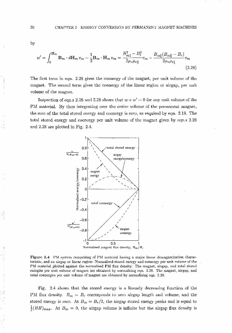
30 CHAPTER 2 ENERGY CONVERSION BY PERMANENT MAGNET MACHINES
by
Hm B2 - B2 B (B B ) I -1 B dH 1 B H _ mil r mil mil - r W - m . m Vm - - m' m Vm - Vm - Vm
o 2 2f.tof.trll 2f.tof.trll (2.28)
The first term in eqn. 2.28 gives the co energy of the magnet, per unit volume of the
magnet. The second term gives the co energy of the linear region or airgap, per unit
volume of the magnet.
Inspection of eqn.s 2.26 and 2.28 shows that w + w' = 0 for any unit volume of the
PM material. By then integrating over the entire volume of the permanent magnet,
the sum of the total stored energy and co energy is zero, as required by eqn. 2.19. The
total stored energy and coenergy per unit volume of the magnet given by eqn.s 2.26
and 2.28 are plotted in Fig. 2.4.
\ total stored energy 0.8 \
__ w_ \ W(Bm=O) \ airgap
0.6 \ energy/coenergy , /\, G'6 0.4
~ magnet , :;; energy __ '2..,-_ 8 0.2 .r ...... , --- / "-r all "
11 ~ -0.2 § o
total co energy ~
Z -0.4
-0.6 I
I I
I
I
W' -w,-(Bm=O)
-0.8
/..
/ / '-magnet /
/ co energy
-1~=-------~----------~ o 0.5
Normalised magnet flux density, Bm/ Br
Figure 2.4 PM system comprising of PM material having a major linear demagnetisation characteristic, and an airgap or linear region: Normalised stored energy and co energy per unit volume of the PM material plotted against the normalised PM flux density. The magnet, airgap, and total stored energies per unit volume of magnet are obtained by normalising eqn. 2.26. The magnet, air gap , and total co energies per unit volume of magnet are obtained by normalising eqn. 2.28.
Fig. 2.4 shows that the stored energy is a linearly decreasing function of the
PM flux density. Bm = Br corresponds to zero airgap length and volume, and the
stored energy is zero. At Bm = Br /2, the airgap stored energy peaks and is equal to
~(BH)max. At Bm = 0, the airgap volume is infinite but the airgap flux density is
2.4 ELECTROMECHANICAL COUPLING 31
zero. At Bm = 0, the energy stored in the PM is four times greater than the maximum
energy that can be stored in the airgap. In practice, Bm is unlikely to reduce to zero
if the PM is being subject to only its own demagnetising field. At low flux densities,
the stored energy available to generate reluctance torque is relatively high.
The prediction of cogging torque in PM motors has been performed by only deter
mining the co energy in the rotor airgap [Li and SIemon 1988]. Unless the stator teeth
are heavily saturated, the co energy contribution from the stator teeth may be ignored.
The error in neglecting the co energy contribution of the magnet is shown by Fig. 2.4.
The total co energy is negative but the co energy of the airgap is positive. Therefore,
the sign of the co energy is incorrect. This results in the sign of the calculated torque
being incorrect. However, the error in the magnitude of the reluctance torque is the
same as that if the torque is calculated by using only the airgap stored energy. This is
because the airgap energy and co energy both have the same sign and magnitude.
If the PM reluctance torque is calculated by determining only the stored energy in
the airgap, then the error in the stored energy is the difference between the magnitude
of the total stored energy and the airgap stored energy in Fig. 2.4. At high values of
B m, this error is small, but increases substantially as Bm decreases. For example, at
Bm = Br /2, the airgap energy only accounts for half of the total stored energy. [Li
and SIemon 1988] show that the variation in field energy near the stator teeth at the
two ends of a rotor magnet are largely responsible for the generation of PM reluctance
torque. Significant variation in the PM flux density at the ends of the rotor magnet
is to be expected and the flux density is likely to .be low. In this case, the results of
this section suggest that the stored energy or co energy of the magnet should not be
neglected in the calculation of reluctance torque.
2.4 ELECTROMECHANICAL COUPLING
2.4.1 Classical Electromechanical Coupling
In this section electromechanical energy conversion theory is briefly reviewed with re
spect to magnetic fields established by only winding currents. Energised windings and
permanent magnets are introduced in the following sections. Thorough treatments
of electromechanical energy conversion theory, which exclude permanent magnets, are
found in references [White and Woodson 1959], [Woodson and Melcher 1968], and
[Fitzgerald et al. 1983]. By applying the principle of conservation of energy (the first
law of thermodynamics), the balance of energy in a lossless magnetic electromechanical
system may be written as:
[Energy input from] = [Mechanical energy] + [Change in energy stored] (2.29)
electrical source output in magnetic field
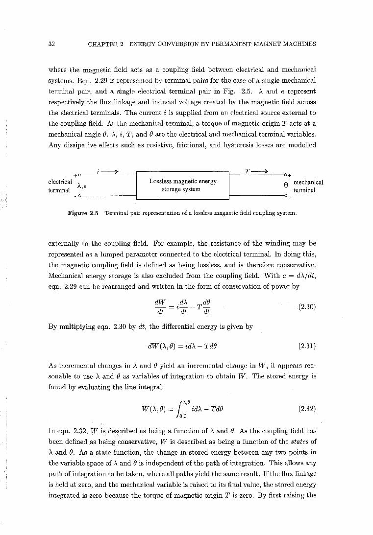
32 CHAPTER 2 ENERGY CONVERSION BY PERMANENT MAGNET MACHINES
where the magnetic field acts as a coupling field between electrical and mechanical
systems. Eqn. 2.29 is represented by terminal pairs for the case of a single mechanical
terminal pair, and a single electrical terminal pair in Fig. 2.5. A and e represent
respectively the flux linkage and induced voltage created by the magnetic field across
the electrical terminals. The current i is supplied from an electrical source external to
the coupling field. At the mechanical terminal, a torque of magnetic origin T acts at a
mechanical angle e. A, i, T, and e are the electrical and mechanical terminal variables.
Any dissipative effects such as resistive, frictional, and hysteresis losses are modelled
i~ ,-------------------1-__ LT~~)~~ +~------~--~1 +
electrical A Lossless magnetic energy 8 mechanical terminal ,e storage system terminal
Figure 2.5 Terminal pair representation of a lossless magnetic field coupling system.
externally to the coupling field. For example, the resistance of the winding may be
represented as a lumped parameter connected to the electrical terminaL In doing this,
the magnetic coupling field is defined as being lossless, and is therefore conservative.
Mechanical energy storage is also excluded from the coupling field. With e = dA/ dt,
eqn. 2.29 can be rearranged and written in the form of conservation of power by
dW = idA _Tde
dt dt dt (2.30)
By multiplying eqn. 2.30 by dt, the differential energy is given by
dW(A, e) = idA - Tde (2.31 )
As incremental changes in A and e yield an incremental change in W, it appears rea
sonable to use A and e as variables of integration to obtain W. The stored energy is
found by evaluating the line integral:
1>..,()
W(A, e) = idA - Tde 0,0
(2.32)
In eqn. 2.32, W is described as being a function of A and e. As the coupling field has
been defined as being conservative, W is described as being a function of the states of
A and e. As a state function, the change in stored energy between any two points in
the variable space of A and e is independent of the path of integration. This allows any
path of integration to be taken, where all paths yield the same result. If the flux linkage
is held at zero, and the mechanical variable is raised to its final value, the stored energy
integrated is zero because the torque of magnetic origin T is zero. By first raising the
2.4 ELECTROMECHANICAL COUPLING 33
mechanical variable to its final value, eqn. 2.32 is integrated more conveniently as
W(>., B) = loA i(>., B) d>' (2.33)
As a state function, W(\ B) is a single-valued function of the independent state vari
abies>. and B. Of particular interest is the torque obtained as a function of the stored
energy. The total differential of W(>., B) is
(2.34)
where the partial derivatives are each taken holding the other state variable constant.
Since>. and B are independent variables, eqn.s 2.31 and 2.34 must be equal for all values
of d>' and dB. Therefore, by equating the respective coefficients of d>' and dB:
. aW(\ B) 2 = a>.
where the partial derivative is taken with B held constant, and
T = _ aW(>.,B) aB
(2.35)
(2.36)
where the partial derivative is taken with>' held constant. Eqn.s 2.35 and 2.36 show
that the current and the torque can be obtained from the partial derivative of the
stored field energy using flux linkage and mechanical angle as independent variables.
The electrical terminal variables are related by an electrical terminal relation ex
pressible in the form
i=i(>.,B) (2.37)
which shows that the current is obtained as a function of the flux linkage and mechanical
angle. This is demonstrated by eqn. 2.35. Solving eqn. 2.37 for>. alternatively yields
>. = >'(i, B) (2.38)
which shows that the flux linkage may be obtained as a function of the current and
mechanical angle. Since flux linkage can be expressed as a function of current and
mechanical angle, it seems reasonable that W = W(>., B) can also be expressed in the
form W = W (i, B), where i replaces>. as an independent state variable. This selection
of independent variables may be described as being more convenient as the terminal
variable i is easily measured and the solutions may also be simpler. To obtain an
equation for torque in terms of (i, B), eqn. 2.31 can be written in a form that involves
34 CHAPTER 2 ENERGY CONVERSION BY PERMANENT MAGNET MACHINES
di and de by first applying the rule of differentiation:
idA = d(Ai) - Adi (2.39)
to eqn. 2.31 to yield the differential co energy
dW' (i, e) = Adi + Tde (2.40)
where
Wi =Ai-W (2.41)
The coenergy Wi (i, e) is defined in relation to stored energy by eqn. 2.41. This
manipulation, which represents conservation of energy in terms of new independent
variables, is called a Legendre transformation [Woodson and Melcher 1968]. To obtain
the coenergy by integrating eqn. 2.40, the mechanical angle is again conveniently raised
first to its final value to give
Wi (i, e) = foi A(i, e) di (2.42)
Wi (i, e) can also be expressed in total differential form. Equating the total differential
to eqn. 2.40 yields
A = aw' (i, e) ai
where the partial derivative is taken with e held constant, and
T = aw' (i, e) ae
(2.43)
(2.44)
where the partial derivative is taken with i held constant. A second useful form of the
torque equation with the independent variables (i, e) is obtained by substituting eqn.
2.41 into eqn. 2.44 to express the torque in terms of energy:
T _ .aA(i,e) aW(i,e) - 2 ae - ae (2.45)
Similarly, by rearranging eqn. 2.41 and substituting into eqn. 2.36, the torque is
expressed with independent variables (A, e) by coenergy:
T = aw' (A, e) _ A ai(A, e) ae ae
(2.46)
2.4 ELECTROMECHANICAL COUPLING 35
2.4.2 Permanent Magnets and Single Energised Winding
Fig. 2.1 is now extended to include a mechanical terminal like Fig. 2.5 such that
simultaneous electrical and mechanical energy conversion may occur. If current and flux
linkage are now assumed to be state functions then hysteresis is excluded, the functional
relationship between these variables is single-valued, and the system is conservative.
The conservation of power is then given by eqn. 2.30:
dW = idA _T dO dt dt dt
and the differential energy is given by eqn. 2.31:
dW().., 0) = idA - TdO
whereby the torque is obtained in terms of stored energy by the classical result of eqn.
2.36:
T = _ 8W(A,0) 80
where the partial derivative is taken with A held constant. The key point is that the
differential energy dW(A, 0) must have the properties of a state function for eqn. 2.31,
and thus eqn. 2.36, to hold. However, this does not imply that dW(A, 0) or W(A, 0) are
required to have the properties of state functions for all values of independent variables
A and O. This imposes the constraint that if any of the independent variables are
outside of a range where W(A, 0) has the properties of a state function, then the torque
cannot be obtained using eqn. 2.36 for those values of the independent variables.
Following classical procedure, the stored energy is obtained by integration of eqn.
2.31. The line integral of eqn. 2.32 is simplified by first mechanically assembling the
system as described in sections 2.2 and 2.4.1. The energy transferred to the system in
raising the flux linkage to a final value is then given by eqn.s 2.4 and 2.5. To determine
the stored component of transferred energy, eqn. 2.5 must be used. In raising the
flux density of the magnet from zero to Be, the system is not conservative. However,
because the magnetisation history is known, the stored energy can be calculated within
these limits, and is found to be zero. The stored energy is therefore obtained by raising
the flux density of the magnet from Be to B m, through which the stored energy is
regarded to have the properties of a state function and is given by eqn. 2.7. The stored
energy is regarded to have the properties of a state function if the demagnetising field
Hm remains within limits such that the demagnetising characteristic remains single
valued. The state function requirement of eqn. 2.31 is therefore satisfied allowing the
torque of the permanent magnet system to be given by eqn. 2.36.
In a conservative system which does not contain permanent magnets but has an
36 CHAPTER 2 ENERGY CONVERSION BY PERMANENT MAGNET MACHINES
energised winding, the relationship between energy and co energy is given by eqn. 2.41.
This relationship is necessarily shown in section 2.7.3 (by setting J = 1) to also hold
for a permanent magnet system having an energised winding. This relationship allows
the torque to be equivalently expressed by the remaining classical results given by eqn.s
2.46, 2.44, and 2.45. The co energy Wi for a permanent magnet system is obtained by
eqn. 2.17. Eqn.s 2.36, 2.46, 2.44, and 2.45 each allow the torque to be obtained for a
permanent magnet system. For these equations, it is essential to hold the independent
variable A or i constant while taking the partial derivative analytically or numerically.
Note that eqn.s 2.36 and 2.44 are more general forms of eqn.s 2.13 and 2.20.
2.4.3 Permanent Magnets and Multiple Energised Windings
Fig. 2.1 is now extended to include J electrical and K mechanical terminal pairs. The
energy differential is then given by
J K
dW = L ijdAj - LTkdOk (2.47) j=l k=l
whereby the torque obtained at the kth mechanical terminal is obtained in terms of
stored energy by
(2.48)
where (A, 0) is now an abbreviation for (A1, . .. ,AJ; 01, . . ; ,OK)' If the system is assem
bled in an analogous manner to that described in section 2.2, the energy transferred
to the system in raising the flux linkages to their final values is given by eqn. 2.5 and
also by
(2.49)
where ij = ij(A1,,,. ,AJ;Ol,'" ,OK)' If there is no hard magnetic material in the
system and the functional relationships between between variables is single-valued,
eqn. 2.49 obtains the stored energy as a state function given that independence of path
is demonstrated by satisfying the following equalities:
Bi1 Bi3 ----, BA3 BA1
Bi2 Bi3 BA3 = BA2' ". (2.50)
For example, in the absence of iron saturation, a two winding system may be repre
sented using inductance coefficients by
(2.51)
2.4 ELECTROMECHANICAL COUPLING 37
(2.52)
It is shown experimentally that L2l = Ll2 [Jones 1967], and these two coefficients
will be replaced by mutual inductance M. Inverting eqn.s 2.51 and 2.52 obtains the
currents, with flux linkages as independent variables:
(2.53)
(2.54)
where B = LnL22 - M2. Eqn.s 2.53 and 2.54 are shown to demonstrate independence
of path:
ail M ai2
aA2 BaAl (2.55)
Substitution of eqn.s 2.53 and 2.54 into 2.49 then yields the stored energy which is
obtained by following any path of integration:
(2.56)
Alternatively, the co energy of the two winding system may be obtained by integrating
eqn.s 2.51 and 2.52. By then taking the partial derivative with respect to a linear
displacement, eqn. 2.1 is obtained.
If a permanent magnet is present, the stored energy is determined by eqn. 2.7.
Section 2.7.3 shows that the relationship
J
W+W' = '2: Ajij j=l
(2.57)
holds for a permanent magnet system with multiple energised windings. Application
of eqn. 2.57 allows the torque to be equivalently expressed by:
(2.58)
T _ oW' (i, 0) k - aO
k (2.59)
38 CHAPTER 2 ENERGY CONVERSION BY PERMANENT MAGNET MACHINES
(2.60)
where (i, 0) is an abbreviation for (i l , ... ,iJ; 01, .. , ,OK)' With CAD packages on elec
tromagnetics, it is known that values of torque can be accurately determined from the
rate of change of the total co energy computed by integrating the co energy density over
the volume of the system, as demonstrated by [Brauer et al. 1984]. This confirms the
validity of eqn. 2.59. The validity of torque eqn.s 2.48, 2.58, and 2.604 are demon
strated by mathematical equivalence to eqn. 2.59, resulting from the proof of eqn. 2.57
given in section 2.7.3.
In many CAD packages, a representation of permanent magnets described in section
2.6 is useful for numerical computation. This representation is shown in section 2.6 to
give an identical rate of change of permanent magnet co energy to that of the second
quadrant representation of coenergy given in section 2.3 byeqn. 2.16. Thus co energy,
as defined by eqn. 2.17, is also shown by equivalence to yield accurate values of torque.
2.5 TORQUE EQUATIONS FOR A LINEAR PERMANENT MAGNET SYSTEM
In the absence of iron saturation, where a single winding is energised, the flux linkage
of the winding may be given by
(2.61 )
where Am is the flux linkage due to the magnet, and L is the inductance of the winding.
Substituting eqn. 2.61 into eqn. 2.45 yields
T _ .dAm .2 dL _ 8W(i,0) - ~ dO + ~ dO 80 (2.62)
The stored energy W(i,O) is determined by eqn. 2.7. Fig. 2.2(a) shows that if Bm
increases towards Bo due to, for example, a winding current increase, the stored energy
of the magnet decreases. A corresponding increase in B in a region surrounding the
magnet yields an increase in the stored energy in that region. Eqn. 2.62 can be
simplified by approximating the energy stored to correspond to mutually exclusive
components provided by the winding and the magnet, whereby
W = W(i = 0,0) + 1/2 L(0)i2 (2.63)
4The 'work function' formulation in [Marinescu and Marinescu 1988] is equivalent to eqn. 2.60, and is supported numerically by comparison to Maxwell stress results.
2.6 CURRENT SHEET MODEL OF A PERMANENT MAGNET 39
and the torque is approximated by
T_.dAm ~'2dL_dW(i=0,O) - ~ dO + 2 ~ dO dO (2.64)
which is given in [Kamerbeek 1973] and is shown to model the motion of a single phase
permanent magnet motor sufficiently accurately in [Schemmann 1971]. The first term
in eqn. 2.64 is used to calculate the torque due to the coupling between a magnet
and an energised winding in brushless permanent magnet machines. The remaining
two terms describe the torques obtained due to reluctance variation with rotational
displacement. Eqn. 2.64 is particularly useful for experimental purposes because all of
the quantities can be measured from electrical and mechanical terminals. All torque
equations for single phase PM motors examined in this Thesis are derived from eqn.
2.64.
2.6 CURRENT SHEET MODEL OF A PERMANENT MAGNET
In a permanent magnet material the relation of B to H may be expressed in the form
of [Stratton 1941, p.13, 129]:
(2.65)
M is the induced polarisation defined by M = XmH where magnetic susceptibility Xm
is defined by Xm = 8M18H. Mo is the residual magnetisation which is non-zero in
permanent magnet regions such that B is non-zero when H = O. Mo is interpreted
as a source of the field. Mo may be replaced by a stationary volume distribution of
current throughout the volume of the magnet of density
J = curl Mo (2.66)
and with a current distribution on the surface bounding the magnet volume of density
K=Moxn (2.67)
where n is the unit outward normal to the surface [Stratton 1941, p. 129]. WithMo
replaced by an equivalent current sheet, eqn. 2.65 reduces to B = J.Lo[H + M] which
describes a B - H characteristic of the first quadrant passing through the origin. The
shifted curve representation is shown in Fig. 2.6(b).
CAD packages on electromagnetics use the technique of shifting the second quad
rant demagnetisation curve to the origin and introduce a suitable current carrying coil
for modelling a permanent magnet [Gupta et al. 1990]. The torque may be obtained
from the current sheet model using Maxwell stress [Gupta et al. 1990] or some other
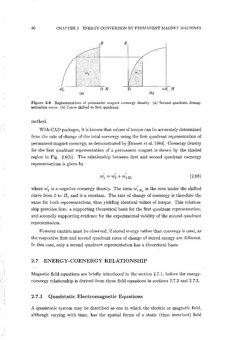
40 CHAPTER 2 ENERGY CONVERSION BY PERMANENT MAGNET MACHINES
B B
(a) (b)
Figure 2.6 Representations of permanent magnet co energy density. (a) Second quadrant demagnetisation curve. (b) Curve shifted to first quadrant.
method.
With CAD packages, it is known that values oftorque can be accurately determined
from the rate of change of the total co energy using the first quadrant representation of
permanent magnet coenergy, as demonstrated by [Brauer et al. 1984]. Coenergy density
for the first quadrant representation of a permanent magnet is shown by the shaded
region in Fig. 2.6(b). The relationship between first and second quadrant co energy
representations is given by
(2.68)
where w~ is a negative co energy density. The term w~ He is the area under the shifted
curve from 0 to He and is a constant. The rate of change of co energy is therefore the
same for both representations, thus yielding identical values of torque. This relation
ship provides first: a supporting theoretical basis for the first quadrant representation;
and secondly supporting evidence for the experimental validity of the second quadrant
representation.
However caution must be observed, if stored energy rather than co energy is used, as
the respective first and second quadrant rates of change of stored energy are different.
In this case, only a second quadrant representation has a theoretical basis.
2.7 ENERGY-COENERGY RELATIONSHIP
Magnetic field equations are briefly introduced in the section 2.7.1, before the energy
co energy relationship is derived from these field equations in sections 2.7.2 and 2.7.3.
2.7.1 Quasistatic Electromagnetic Equations
A quasistatic system may be described as one in which the electric or magnetic field,
although varying with time, has the spatial forms of a static (time invariant) field
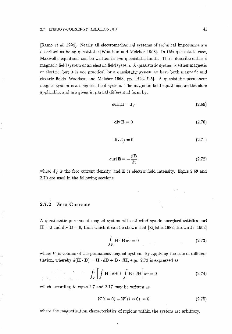
2.7 ENERGY-COENERGY RELATIONSHIP 41
[Ramo et al. 1994]. Nearly all electromechanical systems of technical importance are
described as being quasistatic [Woodson and Melcher 1968]. In this quasistatic case,
Maxwell's equations can be written in two quasistatic limits. These describe either a
magnetic field system or an electric field system. A quasistatic system is either magnetic
or electric, but it is not practical for a quasistatic system to have both magnetic and
electric fields [Woodson and Melcher 1968, pp. B23-B25]. A quasistatic permanent
magnet system is a magnetic field system. The magnetic field equations are therefore
applicable, and are given in partial differential form by:
curlH = Jf
divB = 0
divJf = 0
aB curlE =-at
(2.69)
(2.70)
(2.71)
(2.72)
where J f is the free current density, and E is electric field intensity. Eqn.s 2.69 and
2.70 are used in the following sections.
2.7.2 Zero Currents
A quasi-static permanent magnet system with all windings de-energised satisfies curl
H = 0 and div B = 0, from which it can be shown that [Zijlstra 1982, Brown Jr. 1962]
IvH.BdV=O (2.73)
where V is volume of the permanent magnet system. By applying the rule of differen
tiation, whereby d(H. B) = H· dB + B· dH, eqn. 2.73 is expressed as
Iv [! H . dB + ! B . dH] dv = 0 (2.74)
which according to eqn.s 2.7 and 2.17 may be written as
W (i = 0) + Wi (i = 0) = 0 (2.75)
where the magnetisation characteristics of regions within the system are arbitrary.
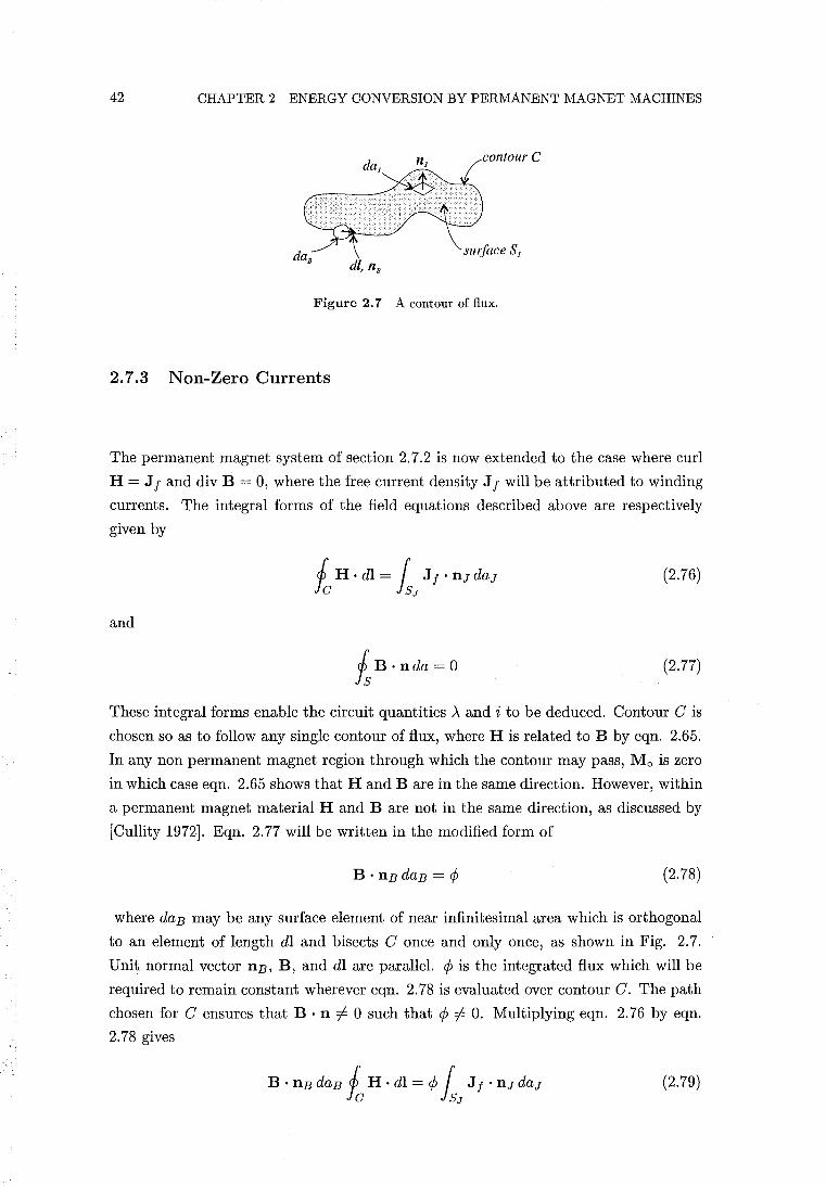
42 CHAPTER 2 ENERGY CONVERSION BY PERMANENT MAGNET MACHINES
contour C
surface SJ dl, nB
Figure 2.7 A contour of flux.
2.7.3 Non-Zero Currents
The permanent magnet system of section 2.7.2 is now extended to the case where curl
H = J f and div B = 0, where the free current density J f will be attributed to winding
currents. The integral forms of the field equations described above are respectively
given by
(2.76)
and
Is B· nda = 0 (2.77)
These integral forms enable the circuit quantities .\ and i to be deduced. Contour C is
chosen so as to follow any single contour of flux, where H is related to B by eqn. 2.65.
In any non permanent magnet region through which the contour may pass, Mo is zero
in which case eqn. 2.65 shows that Hand B are in the same direction. However, within
a permanent magnet material Hand B are not in the same direction, as discussed by
[Cullity 1972]. Eqn. 2.77 will be written in the modified form of
(2.78)
where daB may be any surface element of near infinitesimal area which is orthogonal
to an element of length dl and bisects C once and only once, as shown in Fig. 2.7.
Unit normal vector nB, B, and dl are parallel. ¢ is the integrated flux which will be
required to remain constant wherever eqn. 2.78 is evaluated over contour C. The path
chosen for C ensures that B . n i= 0 such that ¢ i= O. Multiplying eqn. 2.76 by eqn.
2.78 gives
(2.79)
2.7 ENERGY-COENERGY RELATIONSHIP 43
The LHS of eqn. 2.79 is transformed as follows. Let fc H . dl = 2:~1 Hi . dl i
2:~1 Hi . llBi flli' giving
(2.80)
which is equal to
00
L (IHillllBi I cos "IHi) (IBillllBi I cos "IBi )flVi (2.81) i=1
where flVi = flliflaBi is an element of volume. Eqn. 2.81 is simplified by letting
I llBi I = 1 and cos "IBi = 1 to yield
00
L IHiliBil cos "IHiflvi (2.82) i=1
"IHi is also the angle between Hi and Bi, therefore
(2.83)
Vc is the filament volume corresponding to contour C. The RHS of eqn. 2.79 is
transformed as follows. The integral fSJ J f . llJ daJ may be expressed as a sum of
contributions from winding currents crossing surface SJ by 2:;=1 vjij where ij is the
current of the jth winding and Vj is a coefficient corresponding to the jth winding
which may for some values of j be a fractional number or zero. The RHS of eqn. 2.79
may then be expressed by
J J
¢ L vjij = L ACjij (2.84) j=1 j=1
where ACj = ¢Vj. The flux ¢ is a function of the currents and Mo such that ¢ = ¢(i1, ... ,iJ, Mo) and ACj = ACj(i1,. " ,iJ, Mo). Eqn. 2.79 is then expressed as
(2.85)
By then summing the contributions from all the filaments into which the field has been
resolved yields
J
W+W' = LAjij j=1
44 CHAPTER 2 ENERGY CONVERSION BY PERMANENT MAGNET MACHINES
2.8 CONCLUSIONS
Stored energy and co energy have been defined for a permanent magnet system. It has
been shown that either stored energy or co energy may be used to determine permanent
magnet reluctance torque where the magnetisation characteristics of regions within the
system are arbitrary. A specific example of the energy to co energy relationship in a
PM system using a linear PM demagnetisation characteristic and a linear magnet is a
tion characteristic external to the PM has been demonstrated. It has also been shown
how residual magnetism may be incorporated into classical electromechanical coupling
theory. It has therefore been shown how general equations for torque can be derived for
nonlinear permanent magnet systems from classical electromechanical coupling theory.
In doing this it has been shown that the relationship W + Wi = Ai holds for a per
manent magnet system. The approximation made in deriving a simplified equation for
torque in a linear system has been described. Finally, the validity of the first quadrant
representation of the rate of change of co energy within a permanent magnet material,
relevant to CAD systems, has been demonstrated.
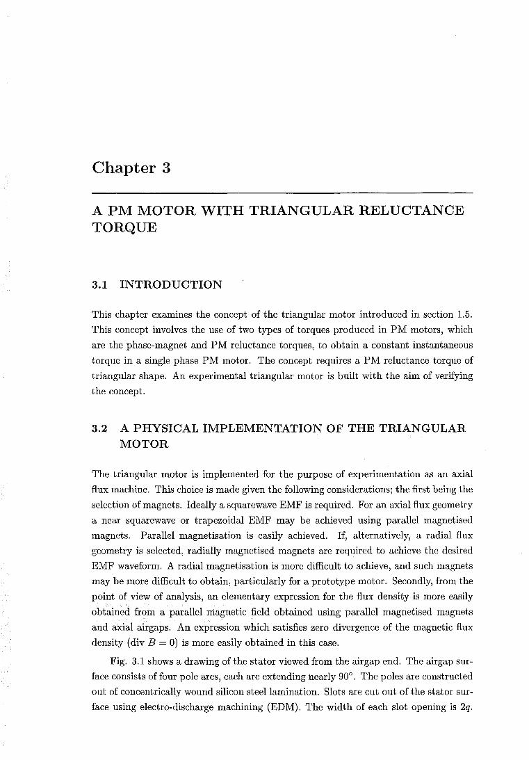
Chapter 3
A PM MOTOR WITH TRIANGULAR RELUCTANCE TORQUE
3.1 INTRODUCTION
This chapter examines the concept of the triangular motor introduced in section 1.5.
This concept involves the use of two types of torques produced in PM motors, which
are the phase-magnet and PM reluctance torques, to obtain a constant instantaneous
torque in a single phase PM motor. The concept requires a PM reluctance torque of
triangular shape. An experimental triangular motor is built with the aim of verifying
the concept.
3.2 A PHYSICAL IMPLEMENTATION OF THE TRIANGULAR MOTOR
The triangular motor is implemented for the purpose of experimentation as an axial
flux machine. This choice is made given the following considerations; the first being the
selection of magnets. Ideally a squarewave EMF is required. For an axial flux geometry
a near squarewave or trapezoidal EMF may be achieved using parallel magnetised
magnets. Parallel magnetisation is easily achieved. If, alternatively, a radial flux
geometry is selected, radially magnetised magnets are required to achieve the desired
EMF waveform. A radial magnetisation is more difficult to achieve, and such magnets
may be more difficult to obtain, particularly for a prototype motor. Secondly, from the
point of view of analysis, an elementary expression for the flux density is more easily
obtained from a parallel magnetic field obtained using parallel magnetised magnets
and axial airgaps. An expression which satisfies zero divergence of the magnetic flux
density (div B = 0) is more easily obtained in this case.
Fig. 3.1 shows a drawing of the stator viewed from the airgap end. The airgap sur
face consists of four pole arcs, each arc extending nearly 900• The poles are constructed
out of concentrically wound silicon steel lamination. Slots are cut out of the stator sur
face using electro-discharge machining (EDM). The width of each slot opening is 2q.
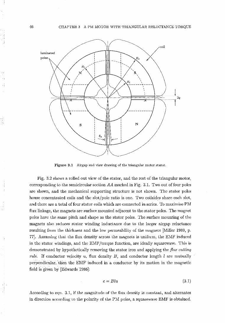
46 CHAPTER 3 A PM MOTOR WITH TRIANGULAR RELUCTANCE TORQUE
coil
poles
Figure 3.1 Airgap end view drawing of the triangular motor stator.
Fig. 3.2 shows a rolled out view of the stator, and the rest of the triangular motor,
corresponding to the semicircular section AA marked in Fig. 3.1. Two out of four poles
are shown, and the mechanical supporting structure is not shown. The stator poles
house concentrated coils and the slot/pole ratio is one. Two coilsides share each slot,
and there are a total of four stator coils which are connected in series. To maximise PM
flux linkage, the magnets are surface mounted adjacent to the stator poles. The magnet
poles have the same pitch and shape as the stator poles. The surface mounting of the
magnets also reduces stator winding inductance due to the larger airgap reluctance
resulting from the thickness and the low permeability of the magnets [Miller 1989, p.
77]. Assuming that the flux density across the magnets is uniform, the EMF induced
in the stator windings, and the EMF/torque function, are ideally squarewave. This is
demonstrated by hypothetically removing the stator iron and applying the flux cutting
rule. If conductor velocity u, flux density B, and conductor length l are mutually
perpendicular, then the EMF induced in a conductor by its motion in the magnetic
field is given by [Edwards 1986]:
e = Blu (3.1)
According to eqn. 3.1, if the magnitude of the flux density is constant, and alternates
in direction according to the polarity of the PM poles, a squarewave EMF is obtained.
3.2 A PHYSICAL IMPLEMENTATION OF THE TRIANGULAR MOTOR 47
----------------------- ---Cl) u
~ 1) .B
Cl) ... -
+' Cl)
a c; s Cl)
'"0 ~ .~
f--- a q:: .:s 1:1
8-----;; I--Cl) .!:1 ~ § -Cl)
0.
-"" - - -----=-:.Il-E== - -- ---
"" - -4 ~
-1il ? a 0 c; ~ s Cl) .:: '"0 's ~ ·s
I-- bO~
a " q:: Cl) +'
1:1 .:: '" 0 .:: Cl) .!:1 0
~ u ;=:
S ~ ... Cl)
0. -r-- ~:l ~
1 ----_.--_.-.- -- --- --
Figure 3.2 Rolled out view of the triangular motor corresponding to the semicircular section AA marked in Fig. 3.1.
In practice, the induced EMF is trapezoidal. In section 3.8.5, a trapezoidal EMF is not
shown to present a problem regarding the torque quality of the triangular motor. This
stator/rotor design therefore satisfies the EMF/torque function characteristic required
for the triangular motor. In order to extend the plateau region of the trapezoidal
EMF within each half cycle as far as possible, the rotor PM and stator pole arcs are
made as full pitched as possible. Interpolar flux leakage, of the rotor in particular, and
mechanical considerations, restrict the pitch of the rotor and stator poles.
48 CHAPTER 3 A PM MOTOR WITH TRIANGULAR RELUCTANCE TORQUE
The second characteristic to be implemented is a triangular reluctance torque. This
requires
1. A PM reluctance geometry which can provide a reluctance torque of satisfactory
triangular shape and sufficient magnitude, completing two cycles per electrical
cycle.
2. An implementation of the reluctance torque geometry which preferably does not
require a second separate set of magnets and an additional flux circuit. The reluc
tance torque and EMF /torque function characteristic are therefore to be obtained
using the same magnets and flux circuit. This single flux circuit requirement cre
ates the following problem. As mentioned, the desired EMF/torque function
requires poles ideally extending a full electrical pole pitch. The triangular re
luctance torque is required to complete a full cycle per half electrical cycle. A
corresponding airgap reluctance cycle must therefore also be completed within an
electrical pole pitch. To produce a triangular reluctance torque with axial par
allel magnetised magnets, the PM poles are required to extend over only a half
electrical pole pitch. However, if the PM poles are shortened to half a pole pitch,
eqn. 3.1 shows that the induced EMF is shortened by a corresponding amount.
The plateau width then extends no more than 900 per electrical half cycle. Such
shortening of the plateau width is unacceptable in this design where only a single
phase is used.
3. A design which enables a PM reluctance torque displacement angle of 1m = 450
electrical. This establishes the correct alignment of the reluctance torque and
the EMF/torque function, as shown by Fig. 1.7. This angle is limited in the
conventional motor designs, as described in section 1.2.2.
These requirements are achieved by the rotor and reluctance plate configuration
shown in Fig. 3.2. An iron flux guide is attached to the underside of each magnet.
Each magnet and flux guide form part of the rotor. Each fluxguide reduces in width to
a half pole pitch. Underneath each flux guide, the PM flux crosses a second air gap to
link the iron reluctance plate. The reluctance plate remains stationary. The reluctance
plate is triangularly modulated, completing a modulation cycle every electrical pole
pitch. The conflicting rotor pole pitch requirements for EMF/torque function shape
and reluctance torque generation are satisfied by using two sets of airgaps, each side
having a different pole pitch. The experimental triangular motor is therefore described
as a double airgap machine. The rotor has the tendency to align itself at the stable
detent reluctance torque position. This occurs where the rotor/reluctance plate airgap
length underneath the half pitch pole of the iron flux guide is minimised. Section 3.6
describes how the triangular reluctance torque is obtained.
3.3 SELECTION OF MAGNETIC MATERIALS 49
In this design, the reluctance plate air gap , rather than the stator airgap, is mod
ulated to produce a reluctance torque. If slotting is ignored, the stator airgap flux
density is uniform across the magnets at any given rotor position. As rotation occurs,
the reluctance airgap modulation causes the uniform flux density across the entire
width of each magnet to be gradually modulated. This causes some modulation of the
EMF /torque function waveform, and this is analysed in section 3.6.2.1.
The design allows any PM reluctance torque displacement angle to be obtained.
This is achieved by rotating the reluctance plate relative to the stator to achieve the
desired displacement angle. The stator and reluctance plate are then fixed mechanically
together at this angle.
3.3 SELECTION OF MAGNETIC MATERIALS
3.3.1 Non Grain Oriented Silicon Steel
The stator, flux guides, and reluctance plate are all constructed out of laminated coils
of non grain oriented (NGO) silicon steel sheet. NGO steel is used mainly in rotating
electrical machinery because of its isotropic magnetism in the sheet plane [Ervens and
Wilmes meier 1985-1994]. NGO steel is therefore ferromagnetic at right angle directions
in the plane of the sheet.
All machining, shearing, and stamping operations on electrical steel sheet produce
stresses which extend for some distance from the strained area and have an adverse
effect on the magnetic characteristics. For example, stamping the airgap surface of
a lamination creates magnetic hardening to a depth corresponding approximately to
the thickness of the lamination. The coiling of the laminations also produces mechan
ical stresses and possible hardening. Stress relief annealing removes the stresses and
improves the magnetic properties. The lamination thickness is 0.5 mm. The steel
lamination 1 is covered with a coat of organic insulation and another coat of inorganic
insulation. After the lamination is coiled, it is annealed in a non-oxidising and non
carburising Argon atmosphere. During the annealing process the organic insulation
layer perishes but the inorganic insulation remains to maintain an inter-lamination
resistance.
3.3.2 Permanent Magnet Materials
In this section, the three main groups of PM materials are briefly described. Section
3.3.2.1 describes in more detail the PM material selected for the triangular motor.
lThe NGO silicon steel used is SG13CP4 from BHP Steel. At a flux density of 1.55 Tesla (T), this steel requires a magnet ising force of 564 Aim, but can also be magnetised to at least 1.8 T. At 1.5 T, core loss is typically 6.5 W IKg.
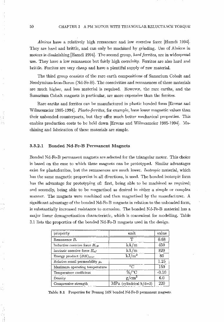
50 CHAPTER 3 A PM MOTOR WITH TRIANGULAR RELUCTANCE TORQUE
Alnicos have a relatively high remanence and low coercive force [Hamdi 1994].
They are hard and brittle, and can only be machined by grinding. Use of Alnicos in
motors is diminishing [Hamdi 1994]. The second group, hard jerrites, are in widespread
use. They have a low remanence but fairly high coercivity. Ferrites are also hard and
brittle. Ferrites are very cheap and have a plentiful supply of raw material.
The third group consists of the rare earth compositions of Samarium Cobalt and
Neodymium-Iron-Boron (Nd-Fe-B). The coercivities and remanences ofthese materials
are much higher, and less material is required. However, the rare earths, and the
Samarium Cobalt magnets in particular, are more expensive than the ferrites.
Rare earths and ferrites can be manufactured in plastic bonded form [Ervens and
Wilmesmeier 1985-1994]. Plasto-jerrites, for example, have lower magnetic values than
their unbonded counterparts, but they offer much better mechanical properties. This
enables production costs to be held down [Ervens and Wilmes meier 1985-1994]. Ma
chining and fabrication of these materials are simple.
3.3.2.1 Bonded Nd-Fe-B Permanent Magnets
Bonded Nd-Fe-B permanent magnets are selected for the triangular motor. This choice
is based on the ease to which these magnets can be prototyped. Similar advantages
exist for plastoferrites, but the remanences are much lower. Isotropic material, which
has the same magnetic properties in all directions, is used. The bonded isotropic form
has the advantage for prototyping of: first, being able to be machined as required;
and secondly, being able to be magnetised as desired in either a simple or complex
manner. The magnets were machined and then magnetised by the manufacturer. A
significant advantage of the bonded Nd-Fe-B magnets in relation to the unbonded form,
is substantially increased resistance to corrosion. The bonded Nd-Fe-B material has a
major linear demagnetisation characteristic, which is convenient for modelling. Table
3.1 lists the properties of the bonded Nd-Fe-B magnets used in the design.
I property unit I value I Remanence Br T 0.68 Inductive coercive force HcB kA/m 450 Intrinsic coercive force HcJ kA/m 820 Energy product (BH)max kJ/mi5 80 Relative recoil permeability Jlr 1.25 Maximum operating temperature DC 150 Temperature coefficient %;oC -0.10 Density g/cmi5 6.0 Compressive strength MPa (cylindrical h/d=2) 220
Table 3.1 Properties for Bremag lON bonded Nd-Fe-B permanent magnets.
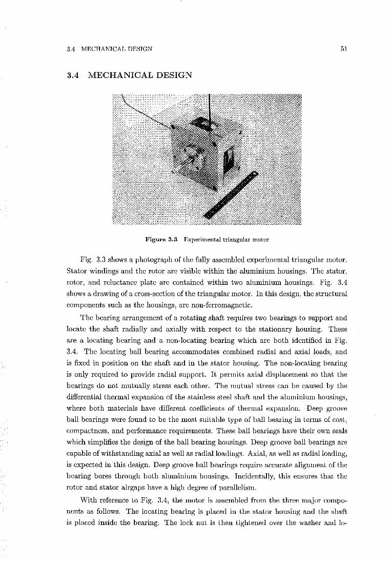
3.4 MECHANICAL DESIGN 51
3.4 MECHANICAL DESIGN
Figure 3.3 Experimental triangular motor
Fig. 3.3 shows a photograph of the fully assembled experimental triangular motor.
Stator windings and the rotor are visible within the aluminium housings. The stator,
rotor, and reluctance plate are contained within two aluminium housings. Fig. 3.4
shows a drawing of a cross-section ofthe triangular motor. In this design, the structural
components such as the housings, are non-ferromagnetic.
The bearing arrangement of a rotating shaft requires two bearings to support and
locate the shaft radially and axially with respect to the stationary housing. These
are a locating bearing and a non-locating bearing which are both identified in Fig.
3.4. The locating ball bearing accommodates combined radial and axial loads, and
is fixed in position on the shaft and in the stator housing. The non-locating bearing
is only required to provide radial support. It permits axial displacement so that the
bearings do not mutually stress each other. The mutual stress can be caused by the
differential thermal expansion of the stainless steel shaft and the aluminium housings,
where both materials have different coefficients of thermal expansion. Deep groove
ball bearings were found to be the most suitable type of ball bearing in terms of cost,
compactness, and performance requirements. These ball bearings have their own seals
which simplifies the design of the ball bearing housings. Deep groove ball bearings are
capable of withstanding axial as well as radial loadings. Axial, as well as radial loading,
is expected in this design. Deep groove ball bearings require accurate alignment of the
bearing bores through both aluminium housings. Incidentally, this ensures that the
rotor and stator airgaps have a high degree of parallelism.
With reference to Fig. 3.4, the motor is assembled from the three major compo
nents as follows. The locating bearing is placed in the stator housing and the shaft
is placed inside the bearing. The lock nut is then tightened over the washer and 10-
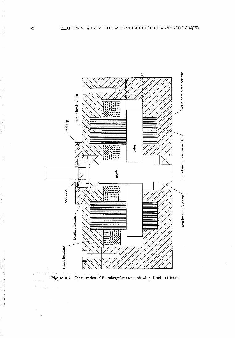
52 CHAPTER 3 A PM MOTOR WITH TRIANGULAR RELUCTANCE TORQUE
Figure 3.4 Cross-section of the triangular motor showing structural detail.
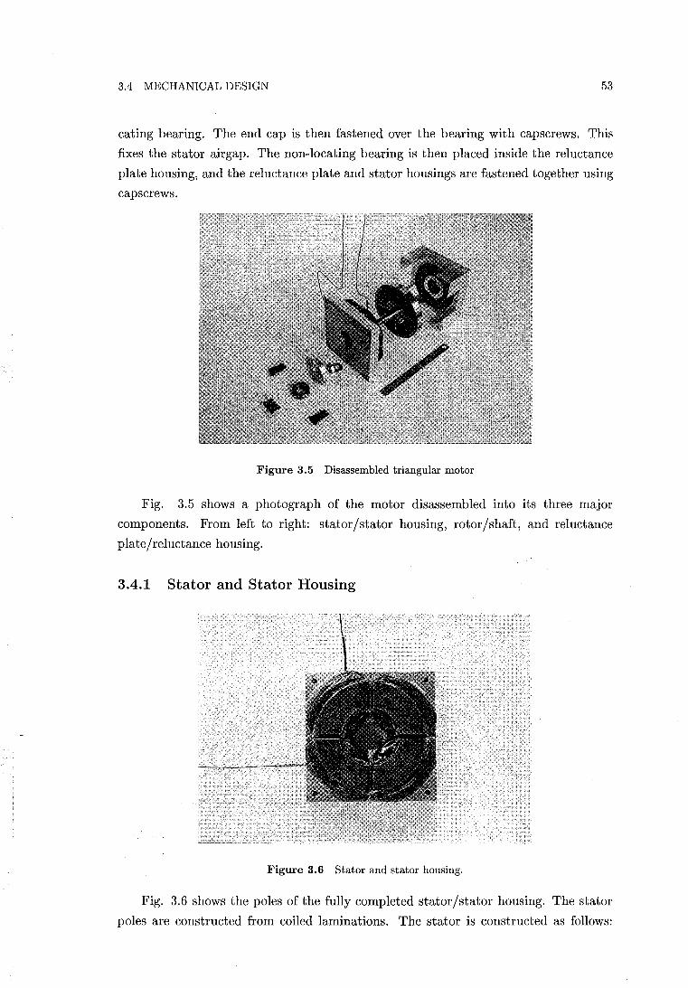
3.4 MECHANICAL DESIGN 53
eating bearing. The end cap is then fastened over the bearing with capscrews. This
fixes the stator airgap. The non-locating bearing is then placed inside the reluctance
plate housing, and the reluctance plate and stator housings are fastened together using
capscrews.
Figure 3.5 Disassembled triangular motor
Fig. 3.5 shows a photograph of the motor disassembled into its three major
components. From left to right: stator/stator housing, rotor/shaft, and reluctance
plate/reluctance housing.
3.4.1 Stator and Stator Housing
Figure 3.6 Stator and stator housing.
Fig. 3.6 shows the poles of the fully completed stator/stator housing. The stator
poles are constructed from coiled laminations. The stator is constructed as follows:
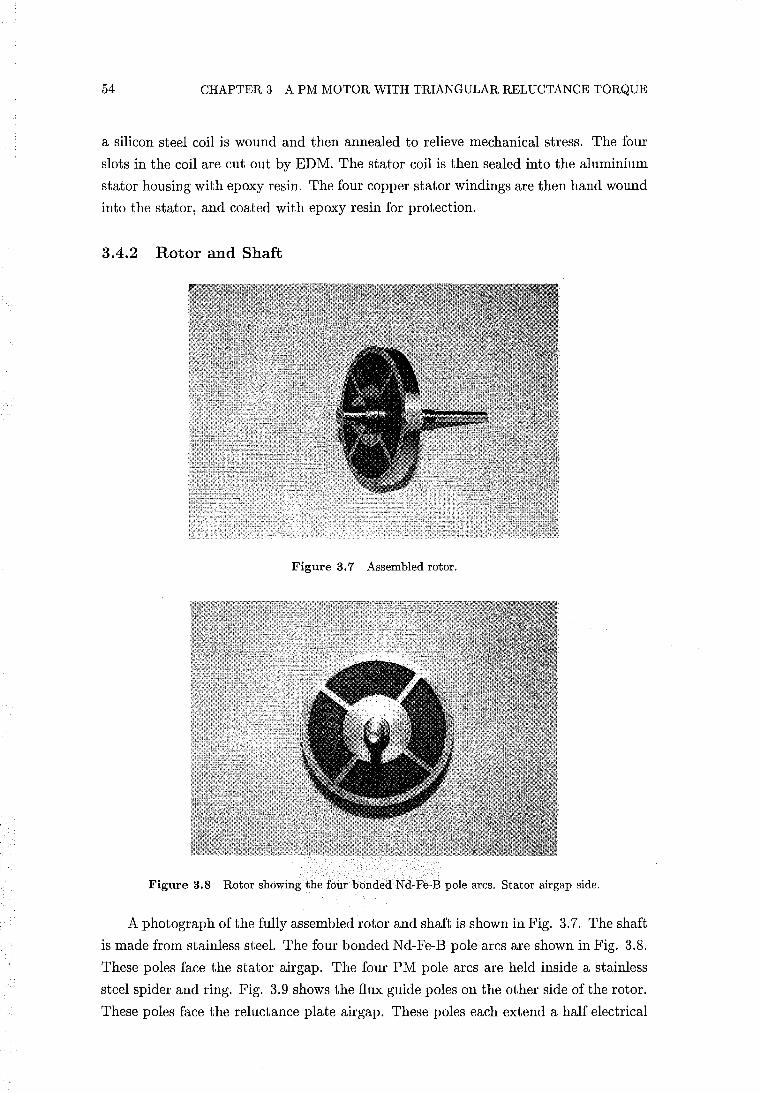
54 CHAPTER 3 A PM MOTOR WITH TRIANGULAR RELUCTANCE TORQUE
a silicon steel coil is wound and then annealed to relieve mechanical stress. The four
slots in the coil are cut out by EDM. The stator coil is then sealed into the aluminium
stator housing with epoxy resin. The four copper stator windings are then hand wound
into the stator, and coated with epoxy resin for protection.
3.4.2 Rotor and Shaft
Figure 3.7 Assembled rotor.
Figure 3.8 Rotor showing the four bonded Nd-Fe-B pole arcs. Stator airgap side.
A photograph of the fully assembled rotor and shaft is shown in Fig. 3.7. The shaft
is made from stainless steel. The four bonded Nd-Fe-B pole arcs are shown in Fig. 3.8.
These poles face the stator airgap. The four PM pole arcs are held inside a stainless
steel spider and ring. Fig. 3.9 shows the fiux guide poles on the other side of the rotor.
These poles face the reluctance plate airgap. These poles each extend a half electrical
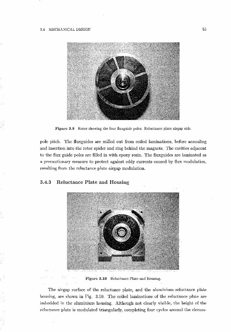
3.4 MECHANICAL DESIGN 55
Figure 3.9 Rotor showing the four fluxguide poles. Reluctance plate airgap side.
pole pitch. The fluxguides are milled out from coiled laminations, before annealing
and insertion into the rotor spider and ring behind the magnets. The cavities adjacent
to the flux guide poles are filled in with epoxy resin. The fluxguides are laminated as
a precautionary measure to protect against eddy currents caused by flux modulation,
resulting from the reluctance plate airgap modulation.
3.4.3 Reluctance Plate and Housing
Figure 3.10 Reluctance Plate and Housing.
The airgap surface of the reluctance plate, and the aluminium reluctance plate
housing, are shown in Fig. 3.10. The coiled laminations of the reluctance plate are
imbedded in the aluminium housing. Although not clearly visible, the height of the
reluctance plate is modulated triangularly, completing four cycles around the circum-
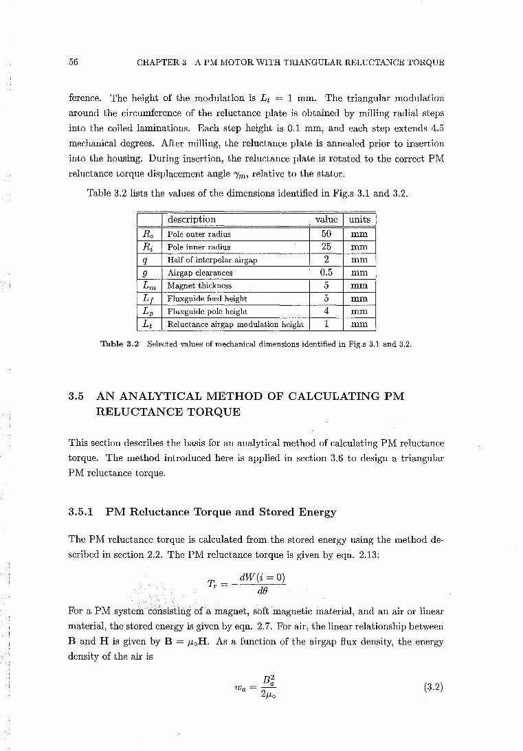
56 CHAPTER 3 A PM MOTOR WITH TRIANGULAR RELUCTANCE TORQUE
ference. The height of the modulation is L t = 1 mm. The triangular modulation
around the circumference of the reluctance plate is obtained by milling radial steps
into the coiled laminations. Each step height is 0.1 mm, and each step extends 4.5
mechanical degrees. After milling, the reluctance plate is annealed prior to insertion
into the housing. During insertion, the reluctance plate is rotated to the correct PM
reluctance torque displacement angle 1m, relative to the stator.
Table 3.2 lists the values of the dimensions identified in Fig.s 3.1 and 3.2.
I description I value I units I Ro Pole outer radius 50 mm Ri Pole inner radius 25 mm q Half of interpolar airgap 2 mm
9 Airgap clearances 0.5 mm Lm Magnet thickness 5 mm Lj Fluxguide feed height 5 mm Lp Fluxguide pole height 4 mm L t Reluctance airgap modulation height 1 mm
Table 3.2 Selected values of mechanical dimensions identified in Fig.s 3.1 and 3.2.
3.5 AN ANALYTICAL METHOD OF CALCULATING PM RELUCTANCE TORQUE
This section describes the basis for an analytical method of calculating PM reluctance
torque. The method introduced here is applied in section 3.6 to design a triangular
PM reluctance torque.
3.5.1 PM Reluctance Torque and Stored Energy
The PM reluctance torque is calculated from the stored energy using the method de
scribed in section 2.2. The PM reluctance torque is given by eqn. 2.13:
To __ dW(i = 0) T - de
For a PM system consisting of a magnet, soft magnetic material, and an air or linear
material, the stored energy is given by eqn. 2.7. For air, the linear relationship between
Band H is given by B = MoH. As a function of the airgap flux density, the energy
density of the air is
(3.2)
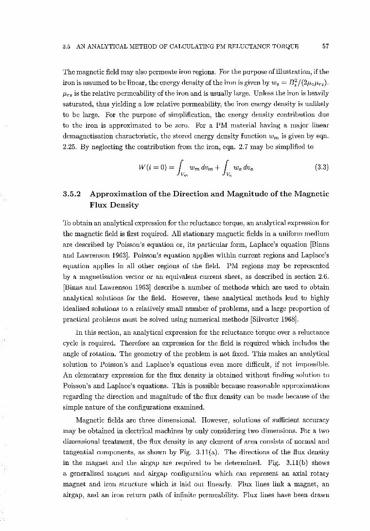
3.5 AN ANALYTICAL METHOD OF CALCULATING PM RELUCTANCE TORQUE 57
The magnetic field may also permeate iron regions. For the purpose of illustration, if the
iron is assumed to be linear, the energy density of the iron is given by Ws = B; /(2f,Lof,Lrs).
f,Lrs is the relative permeability ofthe iron and is usually large. Unless the iron is heavily
saturated, thus yielding a low relative permeability; the iron energy density is unlikely
to be large. For the purpose of simplification, the energy density contribution due
to the iron is approximated to be zero. For a PM material having a major linear
demagnetisation characteristic, the stored energy density function Wm is given by eqn.
2.25. By neglecting the contribution from the iron, eqn. 2.7 may be simplified to
W(i = 0) = r wmdvm + r wadva iVm iVa (3.3)
3.5.2 Approximation of the Direction and Magnitude of the Magnetic Flux Density
To obtain an analytical expression for the reluctance torque, an analytical expression for
the magnetic field is first required. All stationary magnetic fields in a uniform medium
are described by Poisson's equation or, its particular form, Laplace's equation [Binns
and Lawrenson 1963]. Poisson's equation applies within current regions and Laplace's
equation applies in all other regions of the field. PM regions may be represented
by a magnetisation vector or an equivalent current sheet, as described in section 2.6.
[Binns and Lawrenson 1963] describe a number of methods which are used to obtain
analytical solutions for the field. However, these analytical methods. lead to highly
idealised solutions to a relatively small number of problems, and a large proportion of
practical problems must be solved using numerical methods [Silvester 1968].
In this section, an analytical expression for the reluctance torque over a reluctance
cycle is required. Therefore an expression for the field is required which includes the
angle of rotation. The geometry of the problem is not fixed. This makes an analytical
solution to Poisson's and Laplace's equations even more difficult, if not impossible.
An elementary expression for the flux density is obtained without finding solution to
Poisson's and Laplace's equations. This is possible because reasonable approximations
regarding the direction and magnitude of the flux density can be made because of the
simple nature of the configurations examined.
Magnetic fields are three dimensional. However, solutions of sufficient accuracy
may be obtained in electrical machines by only considering two dimensions. For a two
dimensional treatment, the flux density in any element of area consists of normal and
tangential components, as shown by Fig. 3.11(a). The directions of the flux density
in the magnet and the air gap are required to be determined. Fig. 3.11(b) shows
a generalised magnet and airgap configuration which can represent an axial rotary
magnet and iron structure which is laid out linearly. Flux lines link a magnet, an
airgap, and an iron return path of infinite permeability. Flux lines have been drawn
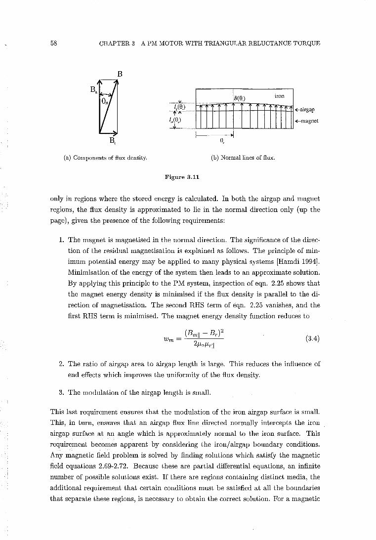
58 CHAPTER 3 A PM MOTOR WITH TRIANGULAR RELUCTANCE TORQUE
B
(a) Components of flux density.
Figure 3.11
IBee')
e,
(b) Normal lines of flux.
iron
~airgap
+-magnet
only in regions where the stored energy is calculated. In both the airgap and magnet
regions, the flux density is approximated to lie in the normal direction only (up the
page), given the presence of the following requirements:
1. The magnet is magnetised in the normal direction. The significance of the direc
tion of the residual magnetisation is explained as follows. The principle of min
imum potential energy may be applied to many physical systems [Hamdi 1994].
Minimisation of the energy of the system then leads to an approximate solution.
By applying this principle to the PM system, inspection of eqn. 2.25 shows that
the magnet energy density is minimised if the flux density is parallel to the di
rection of magnetisation. The second RHS term of eqn. 2.25 vanishes, and the
first RHS term is minimised. The magnet energy density function reduces to
(3.4)
2. The ratio of airgap area to airgap length is large. This reduces the influence of
end effects which improves the uniformity of the flux density.
3. The modulation of the airgap length is small.
This last requirement ensures that the modulation of the iron airgap surface is small.
This, in turn, ensures that an airgap flux line directed normally intercepts the iron
airgap surface at an angle which is approximately normal to the iron surface. This
requirement becomes apparent by considering the iron/ airgap boundary conditions.
Any magnetic field problem is solved by finding solutions which satisfy the magnetic
field equations 2.69-2.72. Because these are partial differential equations, an infinite
number of possible solutions exist. If there are regions containing distinct media, the
additional requirement that certain conditions must be satisfied at all the boundaries
that separate these regions, is necessary to obtain the correct solution. For a magnetic
3.5 AN ANALYTICAL METHOD OF CALCULATING PM RELUCTANCE TORQUE 59
field system, there are two boundary conditions which are required to be specified.
These are obtained from the integral forms of eqn.s 2.69 and 2.70, which are eqn.s 2.76
and 2.77, respectively. From eqn. 2.77, the boundary condition
Bnl- Bn2 = 0 (3.5)
is obtained. Subscript n denotes the normal component to the boundary surface, and
the numerical subscripts identify two different media. Eqn. 3.5 states that the normal
component of B must be continuous at the boundary. The second boundary condition
is obtained from eqn. 2.76, in the absence of current sheets, as
Htl - Ht2 = 0 (3.6)
where subscript t denotes the tangential component to the boundary surface. Eqn.
3.6 states that the tangential component of H must be continuous at the boundary.
Solutions at media boundaries, in which the relative permeabilities are different, are
discontinuous. This may result in the magnitude and direction of the flux density
changing abruptly at the boundary. An ironjairgap boundary, in which the iron is
assumed to be infinitely permeable, is an example of a limiting case. If the iron per
meability is infinite, B within the iron is infinite unless H is zero, since B = /-tH. An
infinite flux density is prohibited by the requirement that the divergence of B is zero.
H must therefore be zero within the iron. The boundary condition of eqn. 3.6 requires
that the tangential component of H be continuous at the boundary. The tangential
component of H on the airgap boundary must also be zero. As a result, only a normal
component of airgap flux density exists, and airgap flux lines intersect the iron at angles
normal to the boundary surface [Silvester 1968]. This ironjaitgap boundary solution
serves the purpose of determining the correct direction of the airgap flux lines at the
ironjairgap surface in Fig. 3.1l(b). It shows that the directions ofthe airgap flux lines
into the ironjairgap surface drawn in Fig. 3.1l(b) are approximations of the correct
solution, if the iron surface is modulated.
The specification that flux lines cross the boundary at a normal angle is known as
a Neumann boundary condition [Brauer 1988]. [Silvester 1968, pp. 179-182] demon
strates that even with a relative permeability of only ten, airgap flux lines will meet an
ironj air interface very nearly at right angles.
In Fig. 3.1l(b), the direction of the airgap flux density at the airgapjmagnet
boundary also requires examination. Given the assumptions that the flux density in
the magnet is parallel to the residual magnetisation, the demagnetising field in the
magnet is obtained from eqn. 2.65 as
IT _ Bm _ Me ilm -
/-te/-Lr /-Lr (3.7)
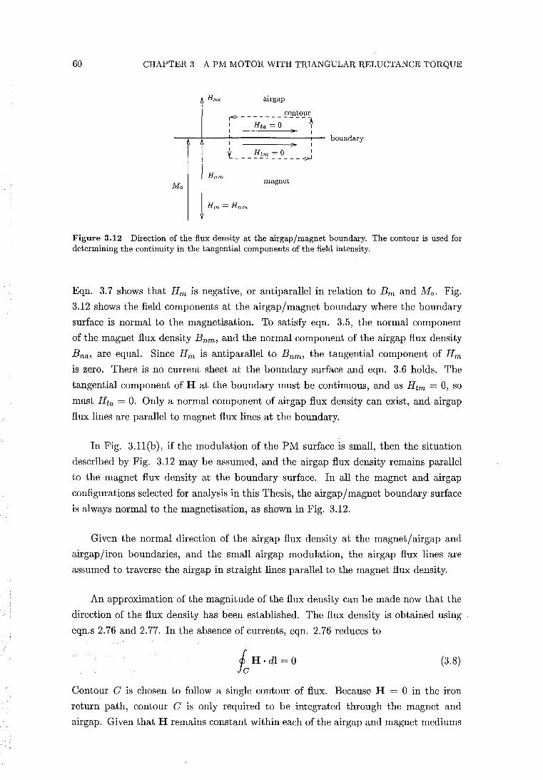
60 CHAPTER 3 A PM MOTOR WITH TRIANGULAR RELUCTANCE TORQUE
Mo
Bna airgap
Bnm
contour 1'<------------1 I Hta = 0 I I ... I
I ... I
t ___ ~!".':. :=_0 ____ ~
magnet
boundary
Figure 3.12 Direction of the flux density at the airgap/magnet boundary. The contour is used for determining the continuity in the tangential components of the field intensity.
Eqn. 3.7 shows that Hm is negative, or antiparallel in relation to Bm and Mo. Fig.
3.12 shows the field components at the airgap/magnet boundary where the boundary
surface is normal to the magnetisation. To satisfy eqn. 3.5, the normal component
of the magnet flux density Bnm , and the normal component of the airgap flux density
B na , are equal. Since Hm is antiparallel to B nm , the tangential component of Hm
is zero. There is no current sheet at the boundary surface and eqn. 3.6 holds. The
tangential component of H at the boundary must be continuous, and as H tm = 0, so
must Hta = O. Only a normal component of airgap flux density can exist, and airgap
flux lines are parallel to magnet flux lines at the boundary.
In Fig. 3.11(b), if the modulation of the PM surface is small, then the.situation
described by Fig. 3.12 may be assumed, and the airgap flux density remains parallel
to the magnet flux density at the boundary surface. In all the magnet and airgap
configurations selected for analysis in this Thesis, the airgap/magnet boundary surface
is always normal to the magnetisation, as shown in Fig. 3.12.
Given the normal direction of the airgap flux density at the magnet/airgap and
airgap/iron boundaries, and the small airgap modulation, the airgap flux lines are
assumed to traverse the air gap in straight lines parallel to the magnet flux density.
An approximation of the magnitude of the flux density can be made now that the
direction of the flux density has been established. The flux density is obtained using
eqn.s 2.76 and 2.77. In the absence of currents, eqn. 2.76 reduces to
(3.8)
Contour C is chosen to follow a single contour of flux. Because H = 0 in the iron
return path, contour C is only required to be integrated through the magnet and
airgap. Given that H remains constant within each of the airgap and magnet mediums
3.5 AN ANALYTICAL METHOD OF CALCULATING PM RELUCTANCE TORQUE 61
along the contour, eqn. 3.8 is evaluated as
(3.9)
where lm and 19 are respectively the magnet and airgap lengths defined in Fig. 3.11(b).
Eqn. 2.77 may be written in the modified form of
(3.10)
where dAm and dAg may be any surface elements, in the magnet and air gap respectively,
of near infinitesimal area which are orthogonal to C. Using eqn.s 3.9, 3.10, and the
constitutive relations Bg = fJoHg for the airgap, and Bm = fJofJrHm + Br for the
magnet, the flux density of contour C within the magnet is obtained as
Br Bme = ----:--
1 + dAm !:..iLl/. dAg lm rr
(3.11)
In Fig. 3.11(b), dAm/dAg = 1 for all contours, and so from eqn. 3.10, Bm = B g. The
magnitude of the flux density for all contours is then given by
(3.12)
3.5.3 A Comparison to the Maxwell Stress Tensor Method
In this section, the approach to calculating reluctance torque developed in the pre
vious sections is compared to the method of torque calculation using Maxwell stress.
The Maxwell stress method is selected for comparison because it is popularly used.
Both methods are compared in relation to obtaining analytical, rather than numeri
cal solutions. Comparison of energy, Maxwell stress, and other methods in numerical
computation are described in depth in the literature.
To begin, the Maxwell stress method is briefly described. For a two dimensional
problem, the force and torque are evaluated by integrating the force density or stress
over a contour surrounding the part of interest. The stresses are represented by field
tensors [Hamdi 1994]. For a two dimensional flux density distribution and a contour
C enclosing a body, the force acting on the body is given by
F = r [~B (B . n) - _1 B2. n] de Jc fJo 2fJo
(3.13)
where n is a unit normal vector to the contour. The contour must be placed entirely
in the air, and the contour must enclose the part on which the force is exerted. The
shape of the contour is chosen arbitrarily. Of particular interest are the components of
62 CHAPTER 3 A PM MOTOR WITH TRIANGULAR RELUCTANCE TORQUE
stress normal and tangential to the contour, which are respectively given by
dlf = _1_ (B2 - B2) dO n 2 n t /-lo
(3.14)
and
(3.15)
Eqn.s 3.14 and 3.15 show that the Maxwell stress method requires the flux density to
be accurately resolved into its normal and tangential components in the local vicinity
of the contour. The unresolved flux density approximation of section 3.5.2 provides an
example in which a meaningless result would be obtained: for a contour of integration
following a path perpendicular to the flux density in Fig. 3.11(b), B t = 0 and the
tangential force is zero. Only the normal force is accounted for. An accurate field
solution is clearly required. The difficulty in obtaining such a solution analytically has
been noted in section 3.5.2.
In contrast, the energy method allows for greater approximation of the local flux
density. This is because stored energy is a global quantity. This allows an elementary
expression for the flux density to be used which is simple enough to allow an analytical
expression for the reluctance torque to be obtained. Because the stored energy is
an analytical expression, the error in taking the derivative with respect to rotational
displacement () is zero. A powerful analytical result is obtained in a simple manner.
This is demonstrated by the example of section 3.6.1. This analytical method yields
a fast solution of the reluctance torque waveform, whilst also providing ready insight
into the influence of parameters.
The application of this analytical energy method is limited to problems where the
airgap is reasonably smooth. This probably excludes cogging torque problems due to
stator slotting because the requirements of section 3.5.2, particularly requirements 2
and 3, are unlikely to be met. The field is therefore unlikely to be described with
sufficient accuracy by the approximation made.
In more complicated magnet and airgap geometries where the field approximation
is still reasonable, the expression for the stored energy may not be integrable in closed
form. The examples of section 4.8, and section V in the paper 'Effects of Airgap and
Magnet Shapes on Permanent Magnet Reluctance Torque' in Appendix A, are such
cases. To obtain the stored energy, numerical evaluation of the integral is required.
Powerful numerical techniques are available [Forsythe et al. 1977] which allow fast
and accurate evaluation of the integral. Because the computation is not intensive,
the energies corresponding to a large number of rotor positions may be evaluated.
Numerical differentiation is then required to obtain the reluctance torque waveform.
Because the evaluation of the stored energy is accurate, the difference between the
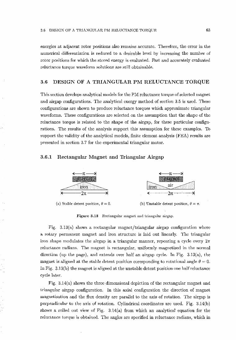
3.6 DESIGN OF A TRIANGULAR PM RELUCTANCE TORQUE 63
energies at adjacent rotor positions also remains accurate. Therefore, the error in the
numerical differentiation is reduced to a desirable level by increasing the number of
rotor positions for which the stored energy is evaluated. Fast and accurately evaluated
reluctance torque waveform solutions are still obtainable.
3.6 DESIGN OF A TRIANGULAR PM RELUCTANCE TORQUE
This section develops analytical models for the PM reluctance torque of selected magnet
and airgap configurations. The analytical energy method of section 3.5 is used. These
configurations are shown to produce reluctance torques which approximate triangular
waveforms. These configurations are selected on the assumption that the shape of the
reluctance torque is related to the shape of the airgap, for these particular configu
rations. The results of the analysis support this assumption for these examples. To
support the validity of the analytical models, finite element analysis (FEA) results are
presented in section 3.7 for the experimental triangular motor.
3.6.1 Rectangular Magnet and Triangular Airgap
~1(------2n------~>1
(a) Stable detent position, () = O. (b) Unstable detent position, () = 7r.
Figure 3.13 Rectangular magnet and triangular airgap.
Fig. 3.13(a) shows a rectangular magnet/triangular air gap configuration where
a rotary permanent magnet and iron structure is laid out linearly. The triangular
iron shape modulates the airgap in a triangular manner, repeating a cycle every 21T'
reluctance radians. The magnet is rectangular, uniformly magnetised in the normal
direction (up the page), and extends over half an airgap cycle. In Fig. 3.13(a), the
magnet is aligned at the stable detent position coresponding to rotational angle () = o. In Fig. 3.13(b) the magnet is aligned at the unstable detent position one half reluctance
cycle later.
Fig. 3.14(a) shows the three dimensional depiction of the rectangular magnet and
triangular airgap configuration. In this axial configuration the direction of magnet
magnetisation and the flux density are parallel to the axis of rotation. The airgap is
perpendicular to the axis of rotation. Cylindrical coordinates are used. Fig. 3.14(b)
shows a rolled out view of Fig. 3.14(a) from which an analytical equation for the
reluctance torque is obtained. The angles are specified in reluctance radians, which in
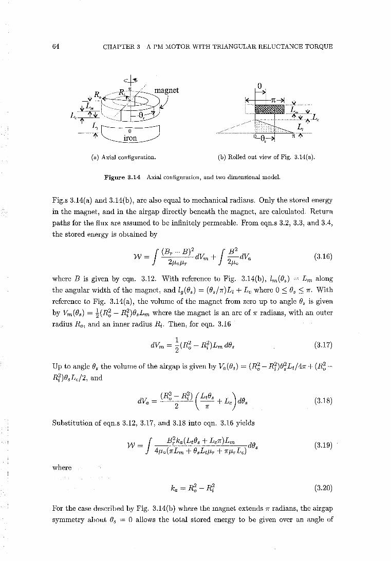
64 CHAPTER 3 A PM MOTOR WITH TRIANGULAR RELUCTANCE TORQUE
(a) Axial configuration. (b) Rolled out view of Fig. 3.14(a).
Figure 3.14 Axial configuration, and two dimensional model.
Fig.s 3.14(a) and 3.14(b), are also equal to mechanical radians. Only the stored energy
in the magnet, and in the airgap directly beneath the magnet, are calculated. Return
paths for the flux are assumed to be infinitely permeable. From eqn.s 3.2, 3.3, and 3.4,
the stored energy is obtained by
(3.16)
where B is given by eqn. 3.12. With reference to Fig. 3.14(b), lm(Os) = Lm along
the angular width of the magnet, and 19(Os) = (Os/7f)Lt + Lc where 0 ~ Os ~ 7f. With
reference to Fig. 3.14(a), the volume of the magnet from zero up to angle Os is given
by Vm(Os) = ~(R~ - Rr)OsLm where the magnet is an arc of 7f radians, with an outer
radius Ro, and an inner radius Ri. Then, for eqn. 3.16 .
(3.17)
Up to angle Os the volume of the airgap is given by Va(Os) = (R~ - Rr)e;Lt/47f + (R~Rr)esLc/2, and
(3.18)
Substitution of eqn.s 3.12, 3.17, and 3.18 into eqn. 3.16 yields
(3.19)
where
(3.20)
For the case described by Fig. 3.14(b) where the magnet extends 7f radians, the airgap
symmetry about Os = 0 allows the total stored energy to be given over an angle of
3.6 DESIGN OF A TRIANGULAR PM RELUCTANCE TORQUE 65
rotation of -1r /2 ::; e ::; 1r /2 by
1
7r /2+8 17r /2-0 W=W + W
o 0 (3.21 )
Because the airgap modulation is discontinuous, mathematically the angle of rotation
is restricted to e = -1r/2 ... 1r/2, and W is a piecewise function. Integrating eqn. 3.19
yields
(3.22)
From eqn.s 2.13 and 3.21, the PM reluctance torque is then obtained as
(3.23)
where -1r/2 < e < 1r/2. If lei « 7rLm + 7rL
c + 1[ eqn. 3.23 is approximated by - - JLrLt Lt 2 '
(3.24)
and Tr (e) approximates a straight line. A second piece-wise function, similar to that of
eqn. 3.23, can be obtained for the second half of the cycle to demonstrate a triangular
reluctance torque. Eqn. 3.23 suggests that if Lm > Lt/-lr, a high quality triangular
reluctance torque waveform can be obtained with triangular airgap modulation.
3.6.2 A Magnetic Reluctance Model of the Triangular Motor
This section describes a magnetic reluctance model of the triangular motor. The mag
net and airgap configuration of the triangular motor differs from that of Fig. 3.14, in
that the iron flux guide separates the magnet and the reluctance airgap. The reluctance
airgap is thus bounded by two iron surfaces. The reluctance model is used to obtain an
estimate of the shape and magnitude of the PM reluctance torque. In section 3.6.2.1,
this reluctance model is also used to obtain an estimate of the EMF/torque function.
The concept of the magnetic reluctance circuit is useful for the estimation of induc
tance [Silvester 1968, pp. 199-207]' but it may also be used to estimate the fluxes and
flux densities in a PM circuit. This, in turn, allows estimation of the stored energy. The
application of the magnetic reluctance circuit concept to a PM system is demonstrated
by simple manipulation of eqn. 3.11. By assuming uniform flux densities throughout
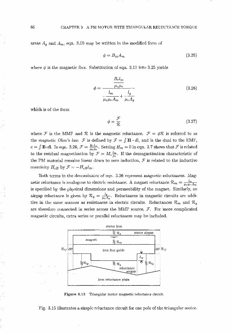
66 CHAPTER 3 A PM MOTOR WITH TRIANGULAR RELUCTANCE TORQUE
areas Ag and Am, eqn. 3.10 may be written in the modified form of
where ¢ is the magnetic flux. Substitution of eqn. 3.11 into 3.25 yields
which is of the form
Brlm
¢ = __ -,-f-L_o.:.-f-L-,-r __
lm 19 ---:--+-f-Lof-LrAm f-LoAg
¢ = F n
(3.25)
(3.26)
(3.27)
where F is the MMF and R is the magnetic reluctance. F = ¢R is referred to as
the magnetic Ohm's law. F is defined by F = J H . dl, and is the dual to the EMF,
e = J E·dl. In eqn. 3.26, F = Ib:lm.. Setting Hm = 0 in eqn. 3.7 shows that F is related /-to/-tr
to the residual magnetisation by F = M o 1m. If the demagnetisation characteristic of /-tr
the PM material remains linear down to zero induction, F is related to the inductive
coercivity HcB by F = -HcBlm.
Both terms in the denominator of eqn. 3.26 represent magnetic reluctances. Mag
netic reluctance is analogous to electric resistance. A magnet reluctance Rm = /-to~~Am is specified by the physical dimensions and permeability of the magnet. Similarly, an
air gap reluctance is given by Rg = IgA' Reluctances in magnetic circuits are addi-/-to 9
tive in the same manner as resistances in electric circuits. Reluctances Rm and Rg
are therefore connected in series across the MMF source, F. For more complicated
magnetic circuits, extra series or parallel reluctances may be included.
stator iron
stator airgap
magnet
iron flux guide
iron reluctance plate
Figure 3.15 Triangular motor magnetic reluctance circuit.
Fig. 3.15 illustrates a simple reluctance circuit for one pole of the triangular motor.
3.6 DESIGN OF A TRIANGULAR PM RELUCTANCE TORQUE 67
The reluctances are identified using resistance symbols. The iron components of the
circuit are assumed to be infinitely permeable and only the reluctances of the airgaps
and magnet are considered. Reluctance Rli represents leakage paths between adjacent
iron flux guides which shunts flux away from the reluctance airgap. The reluctance
of the reluctance airgap is crudely approximated by two components, Rlg and R g.
Estimation of the direction and magnitude of the flux density in the reluctance airgap
is difficult because of the discrete step in the airgap modulation caused by the iron
flux guide. Estimation is also difficult because the reluctance airgap is bounded by two
iron surfaces. Unlike the configuration of section 3.6.1, the flux across the reluctance
airgap is not distributed by the uniform residual magnetisation of a magnet bordering
the airgap surface. The directions of all flux densities are assumed to be parallel to the
vertical or horizontal orientation of their respective reluctance symbols. Within each
reluctance region, the magnitude of the flux density is assumed to remain constant.
Reluctances Rlg and Rg are proportional to the average airgap length in each of their
respective regions. These average airgap lengths vary as the rotor moves across the
reluctance plate. For example, as the rotor begins to move to the right from the
position shown in Fig. 3.15, the average airgap length of reluctance Rg increases, and
Rg increases. At the same time, the average airgap length of Rlg decreases, and Rlg
decreases. Without the extra airgap length L p , Rlg would be of similar magnitude
to R g • No net airgap reluctance modulation would occur yielding no net reluctance
torque. The modulations of Rlg and Rg may then be considered to be in antiphase.
Rlg is considered to be a leakage reluctance because it reduces the magnitude of the
reluctance torque. The reluctance torque is increased by increasing iron flux guide
dimension Lp , but this also increases the size and inertia of the rotor. To obtain a
satisfactory design, a balance of dimensional values is obtained using the reluctance
model.
Because of the high permeability of the iron flux guide and the uniform residual
magnetisation of the magnet, the flux is uniformly distributed along the boundary of
the flux guide and the magnet. Therefore, the magnet flux density and the energy
density across the pitch of the magnet are almost constant at a given rotor position.
Accordingly, a single flux path through the magnet of reluctance Rm is used. This
is clearly different from the configuration of section 3.6.1 where the flux and energy
densities across the pitch of the magnet varies at a given rotor position. The total
magnetic circuit reluctance is given by
(3.28)
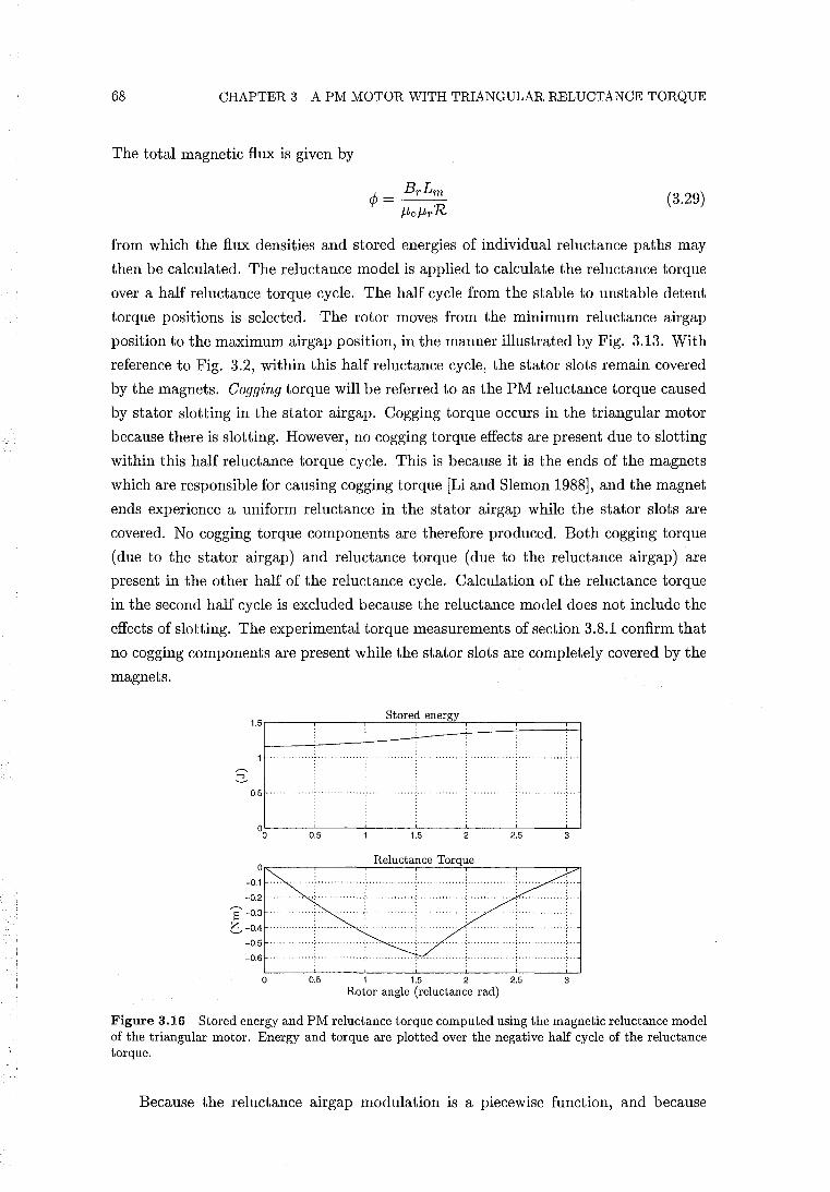
68 CHAPTER 3 A PM MOTOR WITH TRIANGULAR RELUCTANCE TORQUE
The total magnetic flux is given by
(3.29)
from which the flux densities and stored energies of individual reluctance paths may
then be calculated. The reluctance model is applied to calculate the reluctance torque
over a half reluctance torque cycle. The half cycle from the stable to unstable detent
torque positions is selected. The rotor moves from the minimum reluctance airgap
position to the maximum airgap position, in the manner illustrated by Fig. 3.13. With
reference to Fig. 3.2, within this half reluctance cycle, the stator slots remain covered
by the magnets. Gagging torque will be referred to as the PM reluctance torque caused
by stator slotting in the stator airgap. Cogging torque occurs in the triangular motor
because there is slotting. However, no cogging torque effects are present due to slotting
within this half reluctance torque cycle. This is because it is the ends of the magnets
which are responsible for causing cogging torque [Li and SIemon 1988], and the magnet
ends experience a uniform reluctance in the stator airgap while the stator slots are
covered. No cogging torque components are therefore produced. Both cogging torque
(due to the stator airgap) and reluctance torque (due to the reluctance airgap) are
present in the other half of the reluctance cycle. Calculation of the reluctance torque
in the second half cycle is excluded because the reluctance model does not include the
effects of slotting. The experimental torque measurements of section 3.8.1 confirm that
no cogging components are present while the stator slots are completely covered by the
magnets.
Stored energy
1.5CI~~P~
0.5
o~----.-----~~~~~~~----,---~~
-0.1
-0.2
8-0.3
e- -0.4
-0.5
-0.6 .
o 1 1.5 2 Rotor angle (reluctance rad)
Figure 3.16 Stored energy and PM reluctance torque computed using the magnetic reluctance model of the triangular motor. Energy and torque are plotted over the negative half cycle of the reluctance torque.
Because the reluctance airgap modulation is a piecewise function, and because
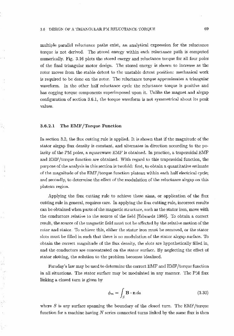
3.6 DESIGN OF A TRIANGULAR PM RELUCTANCE TORQUE 69
multiple parallel reluctance paths exist, an analytical expression for the reluctance
torque is not derived. The stored energy within each reluctance path is computed
numerically. Fig. 3.16 plots the stored energy and reluctance torque for all four poles
of the final triangular motor design. The stored energy is shown to increase as the
rotor moves from the stable detent to the unstable detent position: mechanical work
is required to be done on the rotor. The reluctance torque approximates a triangular
waveform. In the other half reluctance cycle the reluctance torque is positive and
has cogging torque components superimposed upon it. Unlike the magnet and airgap
configuration of section 3.6.1, the torque waveform is not symmetrical about its peak
values.
3.6.2.1 The EMF/Torque Function
In section 3.2, the flux cutting rule is applied. It is shown that if the magnitude of the
stator airgap flux density is constant, and alternates in direction according to the po
larity of the PM poles, a squarewave EMF is obtained. In practice, a trapezoidal EMF
and EMF/torque function are obtained. With regard to this trapezoidal function, the
purpose of the analysis in this section is twofold: first, to obtain a quantitative estimate
of the magnitude of the EMF/torque function plateau within each half electrical cycle;
and secondly, to determine the effect of the modulation of the reluctance airgap on this
plateau region.
Applying the flux cutting rule to achieve these aims, or application of the flux
cutting rule in general, requires care. In applying the flux cutting rule, incorrect results
can be obtained when parts of the magnetic structure, such as the stator iron, move with
the conductors relative to the source of the field [Edwards 1986]. To obtain a correct
result, the source of the magnetic field must not be affected by the relative motion of the
rotor and stator. To achieve this, either the stator iron must be removed, or the stator
slots must be filled in such that there is no modulation of the stator airgap surface. To
obtain the correct magnitude of the flux density, the slots are hypothetically filled in,
and the conductors are concentrated on the stator surface. By neglecting the effect of
stator slotting, the solution to the problem becomes idealised.
Faraday's law may be used to determine the correct EMF and EMF /torque function
in all situations. The stator surface may be modulated in any manner. The PM flux
linking a closed turn is given by
¢m = Is B· nda (3.30)
where S is any surface spanning the boundary of the closed turn. The EMF/torque
function for a machine having N series connected turns linked by the same flux is then
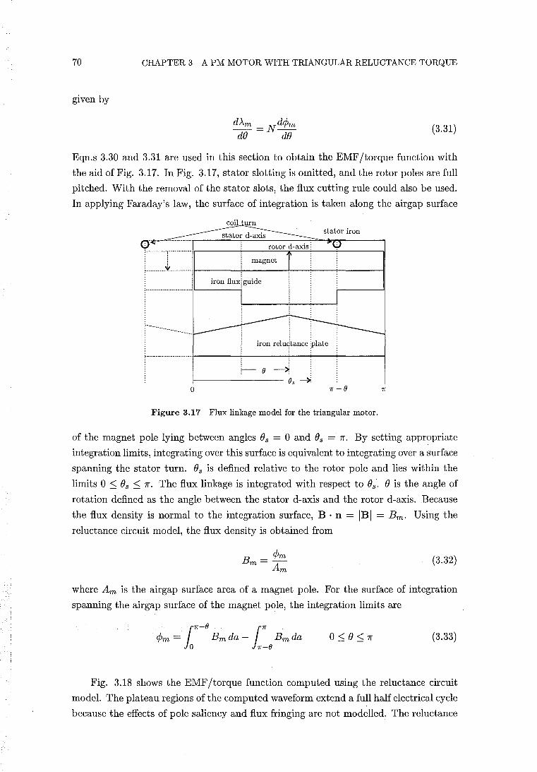
70 CHAPTER 3 A PM MOTOR WITH TRIANGULAR RELUCTANCE TORQUE
given by
(3.31 )
Eqn.s 3.30 and 3.31 are used in this section to obtain the EMF/torque function with
the aid of Fig. 3.17. In Fig. 3.17, stator slotting is omitted, and the rotor poles are full
pitched. With the removal of the stator slots, the flux cutting rule could also be used.
In applying Faraday's law, the surface of integration is taken along the airgap surface
coil urn stator iron
rotor d-axis: ,-----------,------------,�r-----+----"-.:...:..:c'-i:-~~-----;.---__,I
i, f, : t ~ __________ ~ __________ .t,l_--_+i _ffi_a_g_ne_-+-_-e-_-+ ___ --II . !
: _____________________ ...1 iron fluxl guide
! ! !
iron relu1tance :plate
,-------------------------I-----+-----+---;-----!------i i
:~;-(} ~ f--------- O. -> o 1r-O
Figure 3.17 Flux linkage model for the triangular motor,
of the magnet pole lying between angles Os = 0 and Os = Jr. By setting appropriate
integration limits, integrating over this surface is equivalent to integrating over a surface
spanning the stator turn. Os is defined relative to the rotor pole and lies within the
limits 0 ::; Os ::; Jr. The flux linkage is integrated with respect to Os. 0 is the angle of
rotation defined as the angle between the stator d-axis and the rotor d-axis. Because
the flux density is normal to the integration surface, B . n = jBj = Bm. Using the
reluctance circuit model, the flux density is obtained from
B - <Pm m- Am (3.32)
where Am is the airgap surface area of a magnet pole. For the surface of integration
spanning the airgap surface of the magnet pole, the integration limits are
l1r
-O l1r <Pm = Bm da - Bm da
o 1r-O (3.33)
Fig. 3.18 shows the EMF/torque function computed using the reluctance circuit
model. The plateau regions of the computed waveform extend a full half electrical cycle
because the effects of pole saliency and flux fringing are not modelled. The reluctance
3.7 FINITE ELEMENT ANALYSIS
o 234 Rotor angle (elect rad)
71
Figure 3.18 EMF /torque function, 1:iff = N d1;, computed using the reluctance circuit model. N = 600 series connected stator turns. The experimental measurement of the EMF/torque function is also plotted.
model shows that the reluctance airgap causes modulation of the plateau regions. This
is confirmed by the experimental measurement of the EMF/torque function which is
also shown in Fig. 3.18. A modulation of the measured waveform is also clearly
discernible. The measured waveform is trapezoidal in nature. The angular width of
the plateau regions of the measured waveform extend approximately the rotational
angle swept out while the stator slots are completely covered by the magnet poles. The
magnitude of the computed waveform is larger than the measured waveform because
the reluctance model does not account for PM flux leakage at the stator airgap. Neither
does the reluctance model account for effects such as MMF drop in the iron, which if
present, would lower the flux density.
3.7 FINITE ELEMENT ANALYSIS
In this section computational results obtained using finite element analysis are pre
sented for a two dimensional model of the triangular motor. These results correspond
to several selected rotor positions. At these positions, solutions are computed for both
zero and nonzero stator winding currents. The FEA results are compared to the results
obtained using the reluctance circuit model.
3.7.1 The Finite Element Method
The finite element method provides a powerful tool in the CAD design of electrical
machines. It can allow accurate calculation of flux distribution, flux density, winding
inductance, EMF, forces, and torques, under conditions of iron saturation. The method
can also be applied to the structural and thermal analysis of the machine design.
72 CHAPTER 3 A PM MOTOR WITH TRIANGULAR RELUCTANCE TORQUE
The finite element method applied to electromagnetic problems is well documented
in the literature [Lowther and Silvester 1986, Brauer 1988, Hamdi 1994]. In the finite
element method, the field problem is divided into a number of sub domains , or finite el
ements. The magnetic potential distribution within each element is then approximated
by a polynomial. A numerical solution to the field problem is then obtained with re
spect to some optimal criterion [Hamdi 1994]. Principal element types are the triangle,
the quadrilateral, and curvilinear shapes. Element types are defined in terms of the
element shape and the order of the polynomial interpolation. An element contains a
number of nodes, the number of which is related to the type of the element.
After the magnetic potential distribution has been solved, the flux density can be
obtained, and forces or torques can be calculated. The Maxwell stress method is used
in this analysis. The analysis is performed using a commercial FEA software package2 .
3.7.2 Formulation of a Two Dimensional Linear Model
In machines with radial airgap flux, flux paths are generally restricted to the two
dimensional planes of the laminations. For the triangular motor having axial airgap
flux, the laminations are curved, therefore occupying three dimensional space. The flux
within the laminations therefore also follows three dimensional paths. For example,
with reference to Fig. 3.2, the flux paths crossing the airgaps into the laminations are
in the axial direction. With reference to Fig. 3.1, the flux paths in the stator yoke
between poles follow circular arcs in the plane perpendicular to the axis. In order to
avoid a more complicated three dimensional analysis, the triangular motor is rolled
out to form an equivalent two dimensional linear motor model. This is achieved by
rolling the axial motor out at a radius corresponding to where the net tangential force
acts. An appropriate pole width is then calculated. The original axial height and axial
dimensions of the motor remain unchanged. The radius at which the tangential force
acts is assumed to lie where the pole areas inside and outside the radius are equal.
With reference to Fig. 3.1, this radius is given by
The pole pitch for the four pole motor is then given by
21fRt Lpole = -4-
(3.34)
(3.35)
The width of a pole is then selected such that the pole area remains unaltered. The
relative dimensions of the linear motor model corresponding to radius Rt are shown
in Fig. 3.2. Interpolar airgap lengths and slot dimensions remain unaltered. Due to
2The finite element analysis has been performed by Dr J. D. Edwards of the University of Sussex using the [MagNet 5.2 1996] software package.
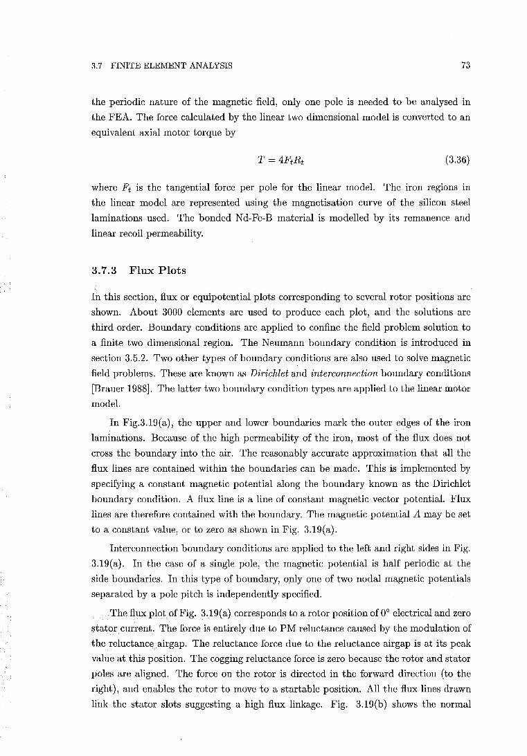
3.7 FINITE ELEMENT ANALYSIS 73
the periodic nature of the magnetic field, only one pole is needed to be analysed in
the FEA. The force calculated by the linear two dimensional model is converted to an
equivalent axial motor torque by
(3.36)
where Ft is the tangential force per pole for the linear model. The iron regions in
the linear model are represented using the magnetisation curve of the silicon steel
laminations used. The bonded Nd-Fe-B material is modelled by its remanence and
linear recoil permeability.
3.7.3 Flux Plots
In this section, flux or equipotential plots corresponding to several rotor positions are
shown. About 3000 elements are used to produce each plot, and the solutions are
third order. Boundary conditions are applied to confine the field problem solution to
a finite two dimensional region. The Neumann boundary condition is introduced in
section 3.5.2. Two other types of boundary conditions are also used to solve magnetic
field problems. These are known as Dirichlet and interconnection boundary conditions
[Brauer 1988]. The latter two boundary condition types are applied to the linear motor
model.
In Fig.3.19(a), the upper and lower boundaries mark the outer edges of the iron
laminations. Because of the high permeability of the iron, most of the flux does not
cross the boundary into the air. The reasonably accurate approximation that all the
flux lines are contained within the boundaries can be made. This is implemented by
specifying a constant magnetic potential along the boundary known as the Dirichlet
boundary condition. A flux line is a line of constant magnetic vector potential. Flux
lines are therefore contained with the boundary. The magnetic potential A may be set
to a constant value, or to zero as shown in Fig. 3.19(a).
Interconnection boundary conditions are applied to the left and right sides in Fig.
3.19(a). In the case of a single pole, the magnetic potential is half periodic at the
side boundaries. In this type of boundary, only one of two nodal magnetic potentials
separated by a pole pitch is independently specified.
The flux plot of Fig. 3.19(a) corresponds to a rotor position of 0° electrical and zero
stator current. The force is entirely due to PM reluctance caused by the modulation of
the reluctance airgap. The reluctance force due to the reluctance airgap is at its peak
value at this position. The cogging reluctance force is zero because the rotor and stator
poles are aligned. The force on the rotor is directed in the forward direction (to the
right), and enables the rotor to move to a startable position. All the flux lines drawn
link the stator slots suggesting a high flux linkage. Fig. 3.19(b) shows the normal
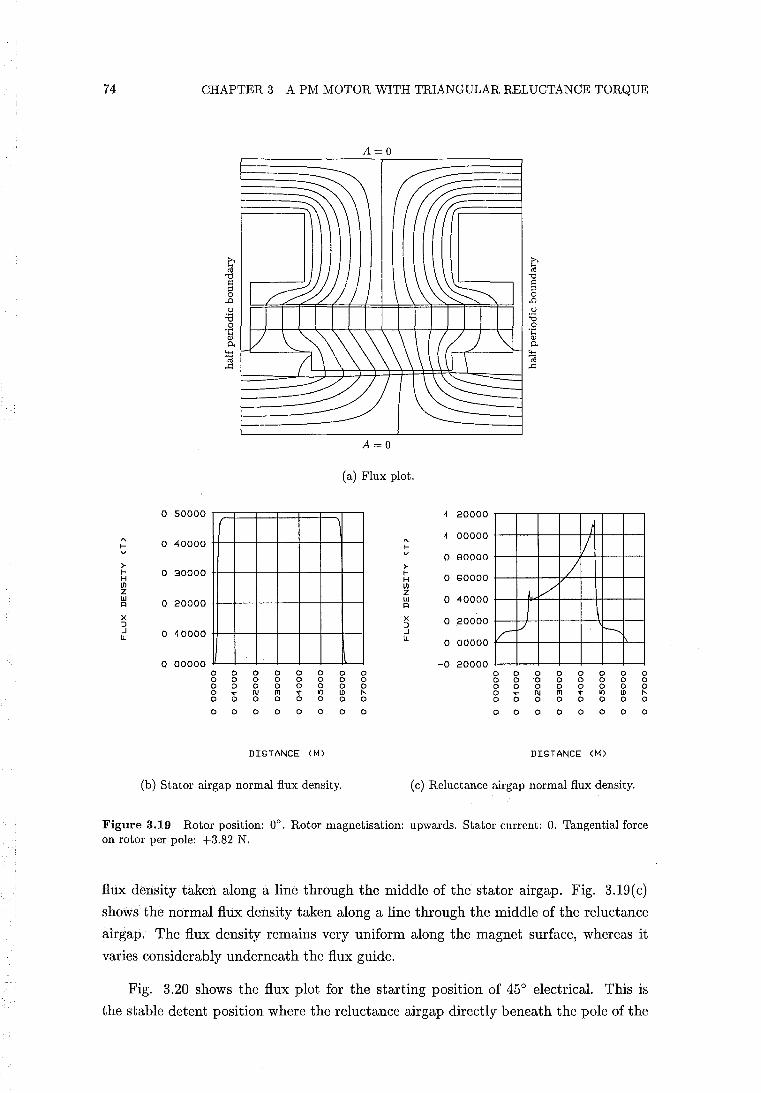
74 CHAPTER 3 A PM MOTOR WITH TRIANGULAR RELUCTANCE TORQUE
A=O
~ ~ cO
'"0 '"0 ~ ~ ;:J ;:J 0 0
.0 .0 u u :e :e 0 0
'!:: '!:: Q) Q)
0. 0.
~ 4-<
Cd ..Q ..Q
A=O
(a) Flux plot.
o 50000 ~ 20000
" o 40000 f-v
>-f- o 30000 H
" ~ 00000
f-v o 90000 >-f- o 60000 H
/ /
II) Z UJ o 20000 I'l
X ::J ..J o ~OOOO Ii.
II) Z UJ o 40000 I'l
X o .20000 ::J ..J Ii. o 00000
I, V r
/ ../ ~
o 00000 -0 20000 0 0 0 0 0 0 0 0 0 0 0 0 0 0 0 0 0 0 0 0 0 0 0 0 0 0 ·0 0 0 0 0 0 0 0 0 0 0 0 0 0 0 0 0 0 0 0 0 0 0 (; N fT1 "t .., LD r-0 0 0 0 0 0 0
0 (; N fT1 "t .., LD r-0 0 0 0 0 0 0
0 0 0 0 0 0 0 0 0 0 0 0 0 0 0 0
DISTANCE <M> DISTANCE <M>
(b) Stator airgap normal flux density. (c) Reluctance airgap normal flux density.
Figure 3.19 Rotor position: 0°. Rotor magnetisation: upwards. Stator current: O. Tangential force on rotor per pole: +3.82 N.
flux density taken along a line through the middle of the stator airgap. Fig. 3.19(c)
shows the normal flux density taken along a line through the middle of the reluctance
airgap. The flux density remains very uniform along the magnet surface, whereas it
varies considerably underneath the flux guide.
Fig. 3.20 shows the flux plot for the starting position of 45° electrical. This is
the stable detent position where the reluctance airgap directly beneath the pole of the
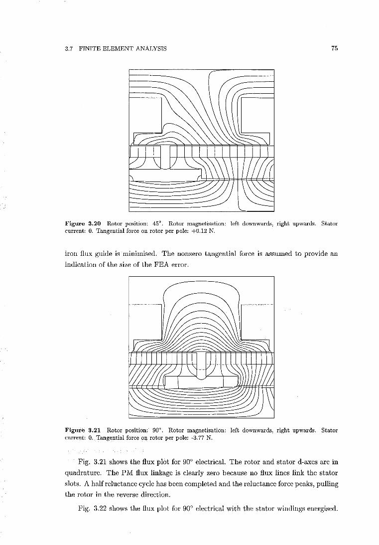
3.7 FINITE ELEMENT ANALYSIS 75
-.----------
Figure 3.20 Rotor position: 45°. Rotor magnetisation: left downwards, right upwards. Stator current: O. Tangential force on rotor per pole: +0.12 N.
iron flux guide is minimised. The nonzero tangential force is assumed to provide an
indication of the size of the FEA error.
Figure 3.21 Rotor position: 90°. Rotor magnetisation: left downwards, right upwards. Stator current: O. Tangential force on rotor per pole: -3.77 N.
Fig. 3.21 shows the flux plot for 90° electrical. The rotor and stator d-axes are in
quadrature. The PM flux linkage is clearly zero because no flux lines link the stator
slots. A half reluctance cycle has been completed and the reluctance force peaks, pulling
the rotor in the reverse direction.
Fig. 3.22 shows the flux plot for 90° electrical with the stator windings energised.
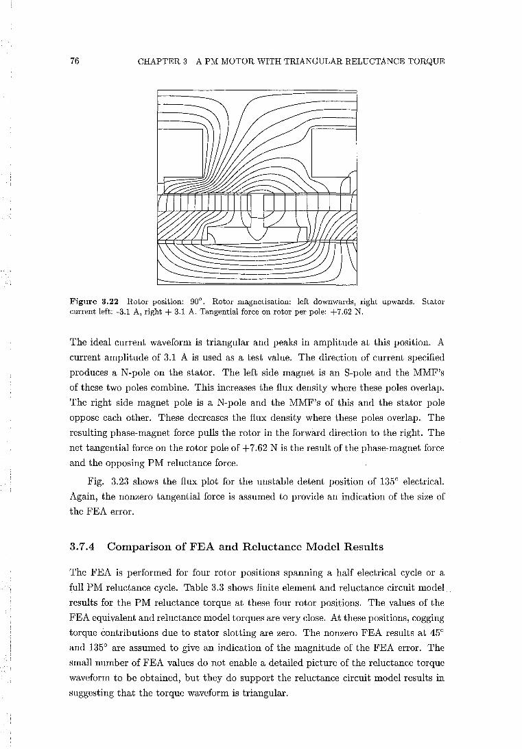
76 CHAPTER 3 A PM MOTOR WITH TRIANGULAR RELUCTANCE TORQUE
Figure 3.22 Rotor position: 90°. Rotor magnetisation: left downwards, right upwards. Stator current left: -3.1 A, right + 3.1 A. Tangential force on rotor per pole: +7.62 N.
The ideal current waveform is triangular and peaks in amplitude at this position. A
current amplitude of 3.1 A is used as a test value. The direction of current specified
produces a N-pole on the stator. The left side magnet is an S-pole and the MMF's
of these two poles combine. This increases the flux density where these poles overlap.
The right side magnet pole is a N-pole and the MMF's of this and the stator pole
oppose each other. These decreases the flux density where these poles overlap. The
resulting phase-magnet force pulls the rotor in the forward direction to the right. The
net tangential force on the rotor pole of + 7.62 N is the result of the phase-magnet force
and the opposing PM reluctance force.
Fig. 3.23 shows the flux plot for the unstable detent position of 135° electrical.
Again, the nonzero tangential force is assumed to provide an indication of the size of
the FEA error.
3.7.4 Comparison of FEA and Reluctance Model Results
The FEA is performed for four rotor positions spanning a half electrical cycle or a
full PM reluctance cycle. Table 3.3 shows finite element and reluctance circuit model
results for the PM reluctance torque at these four rotor positions. The values of the
FEA equivalent and reluctance model torques are very close. At these positions, cogging
torque contributions due to stator slotting are zero. The nonzero FEA results at 45°
and 135° are assumed to give an indication of the magnitude of the FEA error. The
small number of FEA values do not enable a detailed picture of the reluctance torque
waveform to be obtained, but they do support the reluctance circuit model results in
suggesting that the torque waveform is triangular.
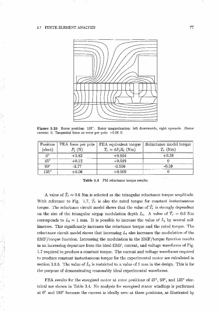
3.7 FINITE ELEMENT ANALYSIS 77
Figure 3.23 Rotor position: 1350• Rotor magnetisation: left downwards, right upwards. Stator
current: O. Tangential force on rotor per pole: +0.06 N.
Position FEA force per pole FEA equivalent torque Reluctance model torque ( elect) Ft (N) Tr = 4Ft Rt (Nm) Tr (Nm)
00 +3.82 +0.604 +0.59 450 +0.12 +0.019 0 900 -3.77 -0.596 -0.59 1350 +0.06 +0.009 0
Table 3.3 PM reluctance torque results.
A value of 'ir ~ 0.6 Nm is selected as the triangular reluctance torque amplitude.
With reference to Fig. 1.7, 'ir is also the rated torque for constant instantaneous
torque. The reluctance circuit model shows that the value of 'ir is strongly dependent
on the size of the triangular airgap modulation depth Lt. A value of'ir = 0.6 Nm
corresponds to L t = 1 mm. It is possible to increase the value of L t by several mil
limetres. This significantly increases the reluctance torque and the rated torque. The
reluctance circuit model shows that increasing L t also increases the modulation of the
EMF /torque function. Increasing the modulation in the EMF/torque function results
in an increasing departure from.the ideal EMF, current, and voltage waveforms of Fig.
1. 7 required to produce a constant torque. The current and voltage waveforms required
to produce constant instantaneous torque for the experimental motor are calculated in
section 3.8.5. The value of Lt is restricted to a value of 1 mm in the design. This is for
the purpose of demonstrating reasonably ideal experimental waveforms.
FEA results for the energised motor at rotor positions of 450, 900
, and 1350 elec
trical are shown in Table 3.4. No analysis for energised stator windings is performed
at 00 and 1800 because the current is ideally zero at these positions, as illustrated by
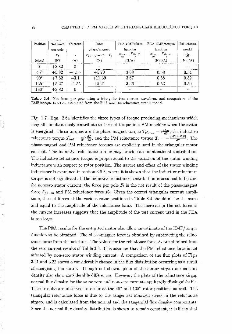
78 CHAPTER 3 A PM MOTOR WITH TRIANGULAR RELUCTANCE TORQUE
Position Net force Current Force FEA EMF/force FEA EMF/torque Reluctance
per pole phase / magnet function function model
Ft i Fph-m = Ft - Fr iG.m. _ Fph-m iG.m. _ Tph_m iG.m.
dx - i dB - i dB
(elect) (N) (A) (N) (N/A) (Nm/A) (Nm/A)
0° +3.82 0 - - - -45° +5.82 +1.55 +5.70 3.68 0.58 0.54 90° +7.62 +3.1 +11.39 3.67 0.58 0.52 135° +5.27 +1.55 +5.21 3.36 0.53 0.50 180° +3.82 0 - - - -
Table 3.4 Net force per pole using a triangular test current waveform, and comparison of the EMF /torque function estimated from the FEA and the reluctance circuit model.
Fig. 1.7. Eqn. 2.64 identifies the three types of torque producing mechanisms which
may all simultaneously contribute to the net torque in a PM machine when the stator
is energised. These torques are the phase-magnet torque Tph-m = i d~e , the inductive
I t t T - 1'2 dL d th PM Itt T - dW(i=O,B) Th re uc ance orque ind -"22 dB' an e re uc ance orque r - - dB . e
phase-magnet and PM reluctance torques are explicitly used in the triangular motor
concept. The inductive reluctance torque may provide an unintentional contribution.
The inductive reluctance torque is proportional to the variation of the stator winding
inductance with respect to rotor position. The nature and effect of the stator winding
inductance is examined in section 3.8.3, where it is shown that the inductive reluctance
torque is not significant. If the inductive reluctance contribution is assumed to be zero
for nonzero stator current, the force per pole Ft is the net result of the phase-magnet
force Fph-m and PM reluctance force Fr. Given the correct triangular currentampli
tude, the net forces at the various rotor positions in Table 3.4 should all be the same
and equal to the amplitude of the reluctance force. The increase in the net force as
the current increases suggests that the amplitude of the test current used in the FEA
is too large.
The FEA results for the energised motor also allow an estimate of the EMF /torque
function to be obtained. The phase-magnet force is obtained by subtracting the reluc
tance force from the net force. The values for the reluctance force Fr are obtained from
the zero current results of Table 3.3. This assumes that the PM reluctance force is not
affected by non-zero stator winding current. A comparison of the flux plots of Fig.s
3.21 and 3.22 shows a considerable change in the flux distribution occurring as a result
of energising the stator. Though not shown, plots of the stator airgap normal flux
density also show considerable differences. However, the plots of the reluctance airgap
normal flux density for the same zero and non-zero currents are hardly distinguishable.
These results are observed to occur at the 45° and 135° rotor positions as well. The
triangular reluctance force is due to the tangential Maxwell stress in the reluctance
airgap, and is calculated from the normal and the tangential flux density components.
Since the normal flux density distribution is shown to remain constant, it is likely that
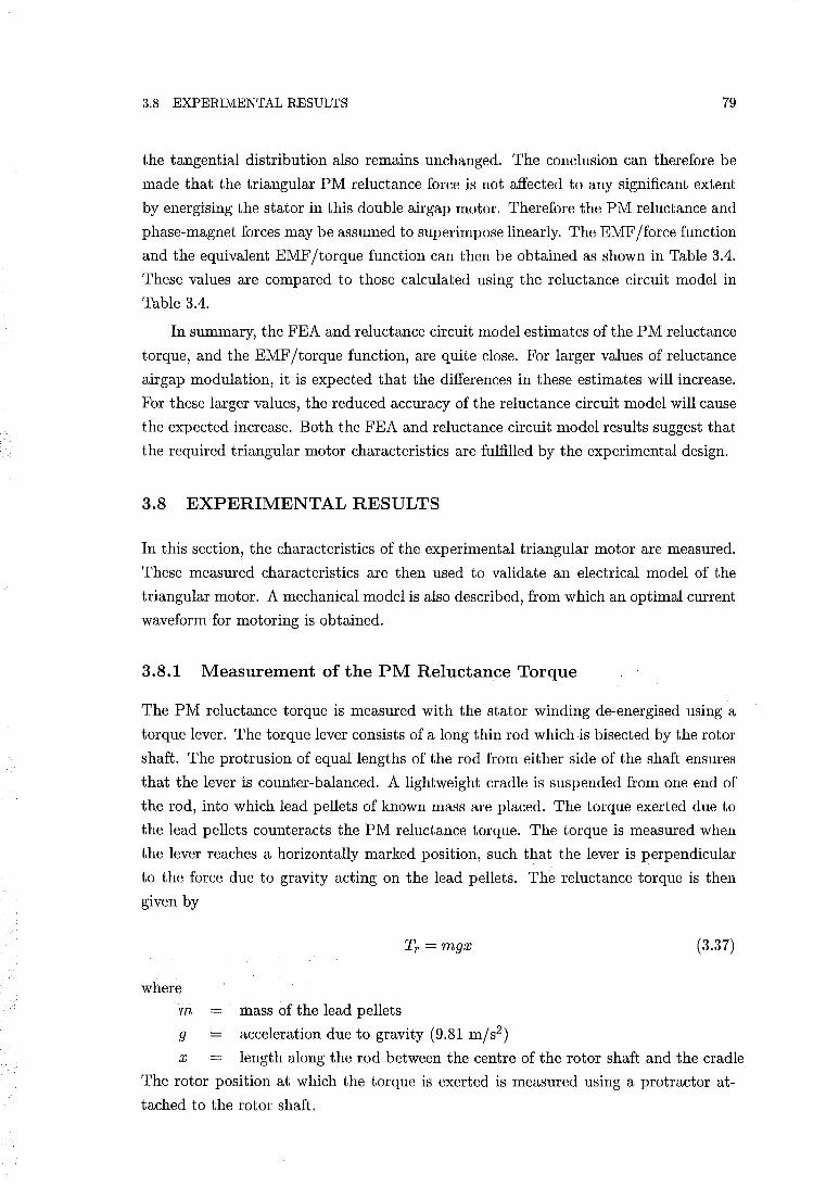
3.8 EXPERIMENTAL RESULTS 79
the tangential distribution also remains unchanged. The conclusion can therefore be
made that the triangular PM reluctance force is not affected to any significant extent
by energising the stator in this double air gap motor. Therefore the PM reluctance and
phase-magnet forces may be assumed to superimpose linearly. The EMF/force function
and the equivalent EMF/torque function can then be obtained as shown in Table 3.4.
These values are compared to those calculated using the reluctance circuit model in
Table 3.4.
In summary, the FEA and reluctance circuit model estimates of the PM reluctance
torque, and the EMF/torque function, are quite close. For larger values of reluctance
airgap modulation, it is expected that the differences in these estimates will increase.
For these larger values, the reduced accuracy of the reluctance circuit model will cause
the expected increase. Both the FEA and reluctance circuit model results suggest that
the required triangular motor characteristics are fulfilled by the experimental design.
3.8 EXPERIMENTAL RESULTS
In this section, the characteristics of the experimental triangular motor are measured.
These measured characteristics are then used to validate an electrical model of the
triangular motor. A mechanical model is also described, from which an optimal current
waveform for motoring is obtained.
3.8.1 Measurement of the PM Reluctance Torque
The PM reluctance torque is measured with the stator winding de-energised using a
torque lever. The torque lever consists of a long thin rod which is bisected by the rotor
shaft. The protrusion of equal lengths of the rod from either side of the shaft ensures
that the lever is counter-balanced. A lightweight cradle is suspended from one end of
the rod, into which lead pellets of known mass are placed. The torque exerted due to
the lead pellets counteracts the PM reluctance torque. The torque is measured when
the lever reaches a horizontally marked position, such that the lever is perpendicular
to the force due to gravity acting on the lead pellets. The reluctance torque is then
given by
Tr = mgx (3.37)
where
m mass of the lead pellets
9 acceleration due to gravity (9.81 m/s2 )
x length along the rod between the centre of the rotor shaft and the cradle
The rotor position at which the torque is exerted is measured using a protractor at
tached to the rotor shaft.
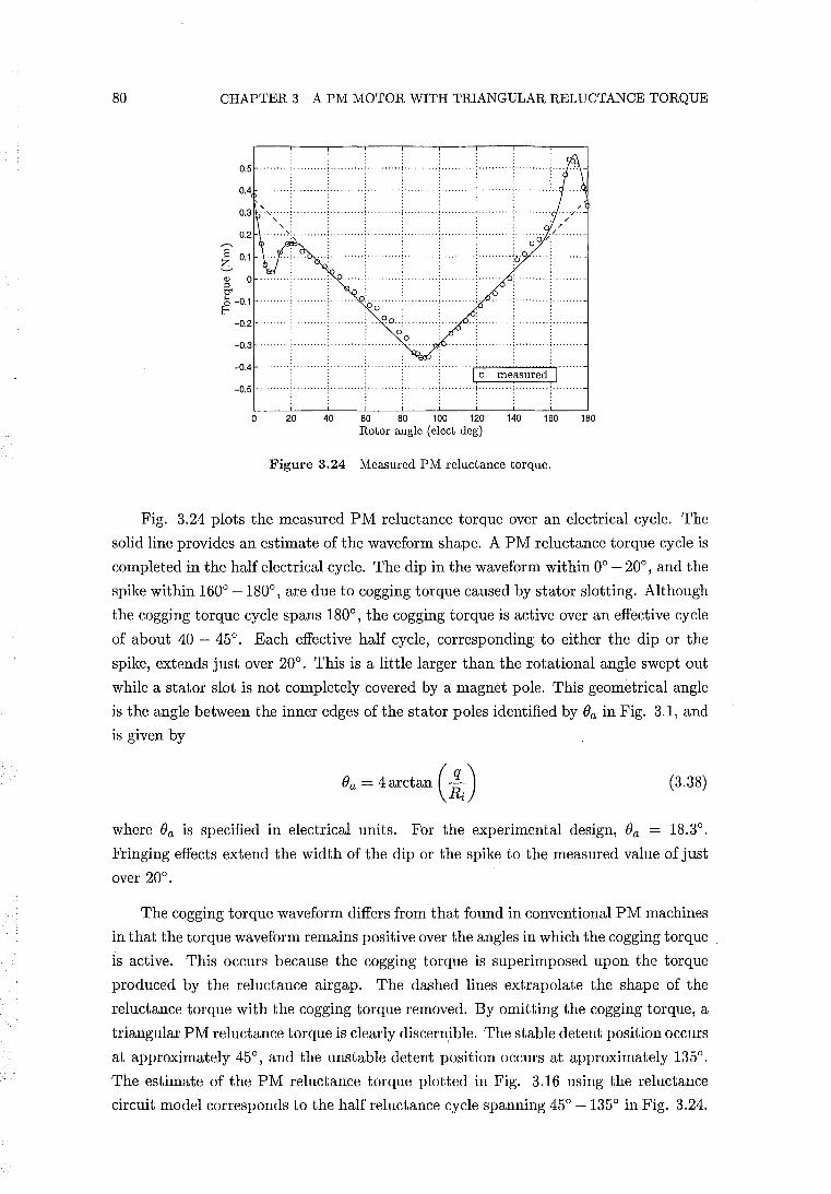
80 CHAPTER 3 A PM MOTOR WITH TRIANGULAR RELUCTANCE TORQUE
o 20 40 60 80 100 120 140 160 180 Rotor angle (elect deg)
Figure 3.24 Measured PM reluctance torque.
Fig. 3.24 plots the measured PM reluctance torque over an electrical cycle. The
solid line provides an estimate of the waveform shape. A PM reluctance torque cycle is
completed in the half electrical cycle. The dip in the waveform within 00 - 200
, and the
spike within 1600 -1800, are due to cogging torque caused by stator slotting. Although
the cogging torque cycle spans 1800, the cogging torque is active over an effective cycle
of about 40 - 450• Each effective half cycle, corresponding to either the dip or the
spike, extends just over 200• This is a little larger than the rotational angle swept out
while a stator slot is not completely covered by a magnet pole. This geometrical angle
is the angle between the inner edges of the stator poles identified by Ba in Fig. 3.1, and
is given by
Ba = 4 arctan (~i) (3.38)
where Ba is specified in electrical units. For the experimental design, Ba = 18.30•
Fringing effects extend the width of the dip or the spike to the measured value of just
over 200•
The cogging torque waveform differs from that found in conventional PM machines
in that the torque waveform remains positive over the angles in which the cogging torque
is active. This occurs because the cogging torque is superimposed upon the torque
produced by the reluctance airgap. The dashed lines extrapolate the shape of the
reluctance torque with the cogging torque removed. By omitting the cogging torque, a
triangular PM reluctance torque is clearly discernible. The stable detent position occurs
at approximately 450, and the unstable detent position occurs at approximately 1350
•
The estimate of the PM reluctance torque plotted in Fig. 3.16 using the reluctance
circuit model corresponds to the half reluctance cycle spanning 450 -1350 in Fig. 3.24.
3.8 EXPERIMENTAL RESULTS 81
The measured amplitude of the triangular reluctance torque of'ir = 0.36 Nm is well
below the predicted value of'ir = 0.60 Nm. The cause of this reduced amplitude was
found to be the permeability of the stainless steel spider shown in Fig.s 3.7-3.9. This
spider supports the magnet poles and the iron flux guides. The effect of the stainless
steel permeability is explained with reference to the reluctance circuit model of Fig.
3.15. The interpolar space between adjacent rotor poles and iron flux guides is occupied
by the stainless steel spider. The reluctance between adjacent flux guides is modelled
by reluctance Rtf. If the relative permeability of the stainless steel is greater than one,
the value of Rtf is decreased. Decreasing Rtf has the effect of shunting flux away from
the reluctance airgap. This reduces the amplitude of the triangular reluctance torque.
Using a value of only /-Lr = 3 for the relative permeability of the stainless steel was
found to reduce the magnitude of the reluctance torque calculated using the reluctance
circuit model to that of the measured reluctance torque. A value of /-Lr = 3 reduces Rtf
by a factor of three, and is equivalent to reducing the interpolar airgaps by the same
factor.
A force of attraction between the Nd-Fe-B magnets and the stainless steel was
noticed after the stainless steel spider had been manufactured. The force of attraction,
and thus also the relative permeability, was found to increase as a magnet was moved
towards the centre of the bar from which the spider was machined. The 304 grade
of austenitic steel is used, which has a theoretical relative permeability of /-Lr = 1.008
[Peckner and Bernstein 1977]. Enquiries were made by the steel supplier regarding the
apparent ferromagnetism in this particular grade of stainless steel. It was discovered
that ferrite impurities form in the stainless rod during manufacturing, increasing in
concentration towards the centre of the rod, giving rise to some ferromagnetism.
The variation of the stainless steel permeability makes measurement and incorpo
ration of the stainless steel permeability into the finite element and reluctance models
very difficult. An attempt was made to measure the relative permeability using the ring
and fluxmeter method described by [Hughes 1960, pp. 74-75J. A ring was machined
out of the rod used to make the stainless steel spider. Most of the rotor interpolar
leakage through the stainless steel between flux guides occurs between radii Ro and
Ri in Fig. 3.1. As the permeability of the stainless steel decreases with increasing
radius, choosing the radius of the test ring is not straight forward. A test ring with an
inner diameter equal to Ri (25 mm) was selected. A primary coil is wound uniformly
around the circumference of the test ring to provide a uniform MMF per unit length.
A secondary coil, connected to the fluxmeter, is wound over the primary. Reversing the
current in the primary coil induces an EMF in the secondary coil which is integrated
by the fluxmeter. Given the magnitude of the current, the number of primary turns,
and the mean circumference of the test ring, H around the mean circumference can be
calculated. B is calculated from the value of the integrated flux, and the cross-sectional
area of the ring. The value of'H in a toroid varies from a maximum at the inner pe-
82 CHAPTER 3 A PM MOTOR WITH TRIANGULAR RELUCTANCE TORQUE
riphery to a minimum at the outer periphery, and the flux density varies accordingly.
H at the mean diameter is the average value for the ring; and if the radial thickness of
the ring does not exceed about one-tenth of the mean diameter, the average value of
B may, without appreciable error, be assumed to be the density at the mean diameter,
which is due to the mean value of H. This corresponds to setting the ratio of outer to
inner diameters of the test ring to a value no greater than do/di = 11/9. The outer
diameter of the test ring was set to the maximum value of 30.5 mm. The relative
permeability of the ring was found to be J-tr = 2.6 - 2.8 over a range of H = 3.6 to 36
kA/m.
The permeability measurement supports using the value of J-tr = 3 for the reluctance
path nIt in the reluctance circuit model. The slightly larger value of J-tr used in the
model compensates for other leakage paths in the stainless steel spider which are not
modelled.
In summary, the PM reluctance torque measurements qualitatively support the
finite element and reluctance circuit model results in demonstrating that the experi
mental design produces a triangular reluctance torque waveform. The estimated results
are also quantitatively supported by the measurement of the stainless steel permeabil
ity.
3.8.2 Measurement of the EMF/Torque Function
The back EMF is measured by driving the motor as a generator under no load. The
measured EMF/torque function of Fig. 3.18 is obtained from the back EMF. The
plateau region within each half cycle extends for approximately 1400• As noted in
section 3.6.2.1, the width of the plateau region extends approximately the rotational
angle swept out in which the stator slots are completely covered by the magnet poles.
This angle, calculated with respect to the pole geometry, is given by
(elect de g) (3.39)
and is slightly larger than the measured plateau width.
The permeability of the stainless steel affects mainly the reluctance airgap flux.
The effect of the stainless steel on the stator airgap is to reduce the total magnetic
circuit reluctance, which increases the stator airgap flux density and the EMF/torque
function by a small amount. For the reluctance model calculation of the EMF/torque
function shown in Fig. 3.18, a value of J-tr = 3 is used for the stainless steel permeability.
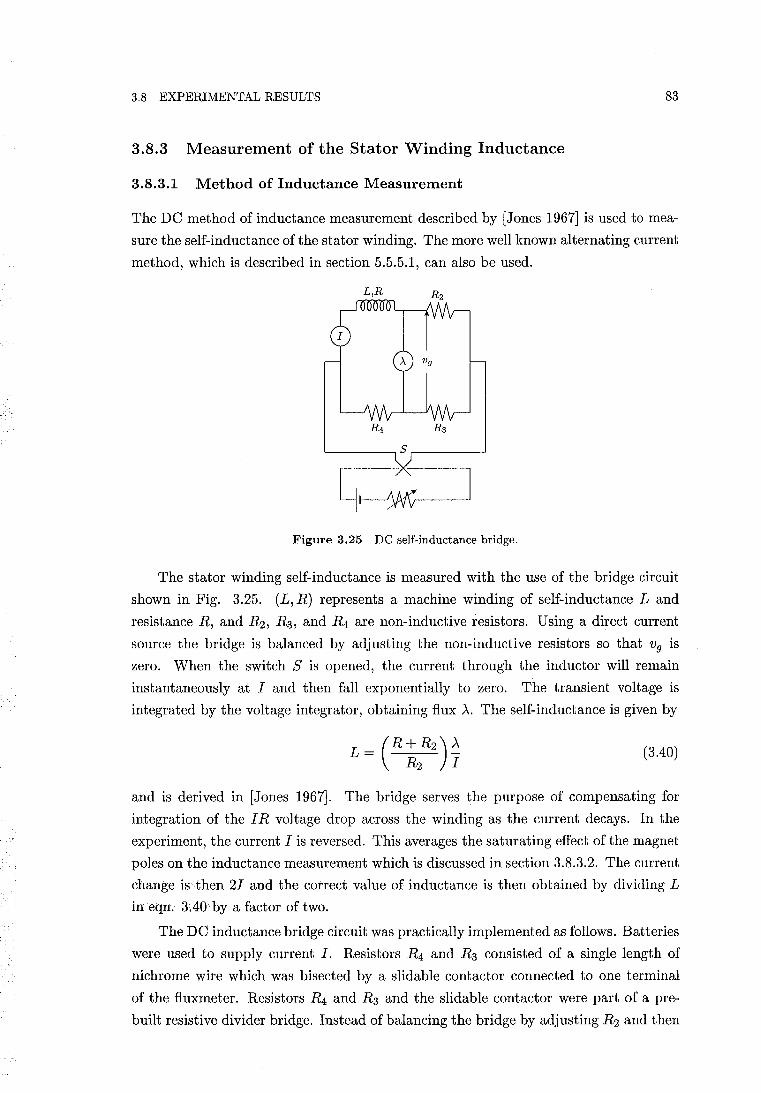
3.8 EXPERIMENTAL RESULTS 83
3.8.3 Measurement of the Stator Winding Inductance
3.8.3.1 Method of Inductance Measurement
The DC method of inductance measurement described by [Jones 1967] is used to mea
sure the self-inductance of the stator winding. The more well known alternating current
method, which is described in section 5.5.5.1, can also be used.
'--___ --, s ,-___ -'
Figure 3.25 DC self-inductance bridge.
The stator winding self-inductance is measured with the use of the bridge circuit
shown in Fig. 3.25. (L, R) represents a machine winding of self-inductance Land
resistance R, and R2, R3, and R4 are non-inductive resistors. Using a direct current
source the bridge is balanced by adjusting the non-inductive resistors so that Vg is
zero. When the switch S is opened, the current through the inductor will remain
instantaneously at I and then fall exponentially to zero. The transient voltage is
integrated by the voltage integrator, obtaining flux A. The self-inductance is given by
(3.40)
and is derived in [Jones 1967]. The bridge serves the purpose of compensating for
integration of the I R voltage drop across the winding as the current decays. In the
experiment, the current I is reversed. This averages the saturating effect of the magnet
poles on the inductance measurement which is discussed in section 3.8.3.2. The current
change is then 21 and the correct value of inductance is then obtained by dividing L
in eqn. 3.40 by a factor of two.
The DC inductance bridge circuit was practically implemented as follows. Batteries
were used to supply current I. Resistors R4 and R3 consisted of a single length of
nichrome wire which was bisected by a slidable contactor connected to one terminal
of the fluxmeter. Resistors R4 and R3 and the slidable contact or were part of a pre
built resistive divider bridge. Instead of balancing the bridge by adjusting R2 and then
84 CHAPTER 3 A PM MOTOR WITH TRIANGULAR RELUCTANCE TORQUE
measuring the R/ R2 ratio, the bridge was balanced by sliding the contactor to adjust
R4 and R3. Once the bridge was balanced the R4/ R3 ratio was measured. Rather
than requiring to measure the resistances, the ratio could simply be determined by
measuring how far along the nichrome wire the slidable contact or was positioned. The
contactor was able to be moved along a rule imbedded in the resistive divider bridge.
The slider distance and thus the R4/ R3 ratio were able to be determined to an accuracy
greater than one part in three thousand. A fluxmeter was used as a voltage integrator.
To enable the bridge to be finely balanced a long length (three meters) of nichrome
wire was used in the resistive divider, and a voltmeter was placed in parallel with the
fluxmeter to balance the bridge voltage (to within tens of micro-volts). A non-inductive
nichrome resistor was used for R2. Factors limiting inductance measurement accuracy
were thermal resistive drift which unbalances the bridge, and the accuracy to which
the fluxmeter could be read.
The DC inductance method is particularly useful for measuring the inductance
of machines containing solid steel. For example, the field windings of a synchronous
machine carry direct currents in normal operation, in which case the field poles may
be constructed out of solid steel. The AC method cannot be applied because the large
eddy currents in the solid steel render the results inapplicable to normal operation.
The DC method also allows the winding resistance to be accurately excluded from
being a source of error, unlike the AC method where the winding resistance must
also be measured. In AC measurements, hysteresis and eddy current core losses are
functions of the number of electrical cycles per second, and affect the measurement.
The empirical relationships describing these losses ani documented in the standard
texts. In the DC method, the inductance measurement is unaffected by the induced
current of a short-circuited secondary winding [Jones 1967, p. 22], and is thus similarly
unaffected by induced eddy current in the iron. This makes the DC method less prone
to errors caused by core losses.
3.8.3.2 Measurement Results
Fig. 3.26 shows the stator winding inductance for a current of 0.5 A. A cycle of
inductance modulation is completed in a half electrical cycle. The waveform changes
little over the range of 0-2 A, suggesting that the current does not saturate the stator
over this current range. The modulation in the inductance is caused by the magnet
poles, and the saliency of the iron flux guides. At 900 the magnet poles are in quadrature
with the rotor poles. At this rotor position, the stator yoke is less saturated by magnet
flux than when the poles are aligned, as is seen by comparing Fig.s 3.19(a) and 3.21.
The stator yoke permeability, and therefore the stator winding inductance are higher at
900• At the quadrature position the iron flux guides provide a lower reluctance path for
stator winding flux crossing the stator airgap, adding to the quadrature inductance.
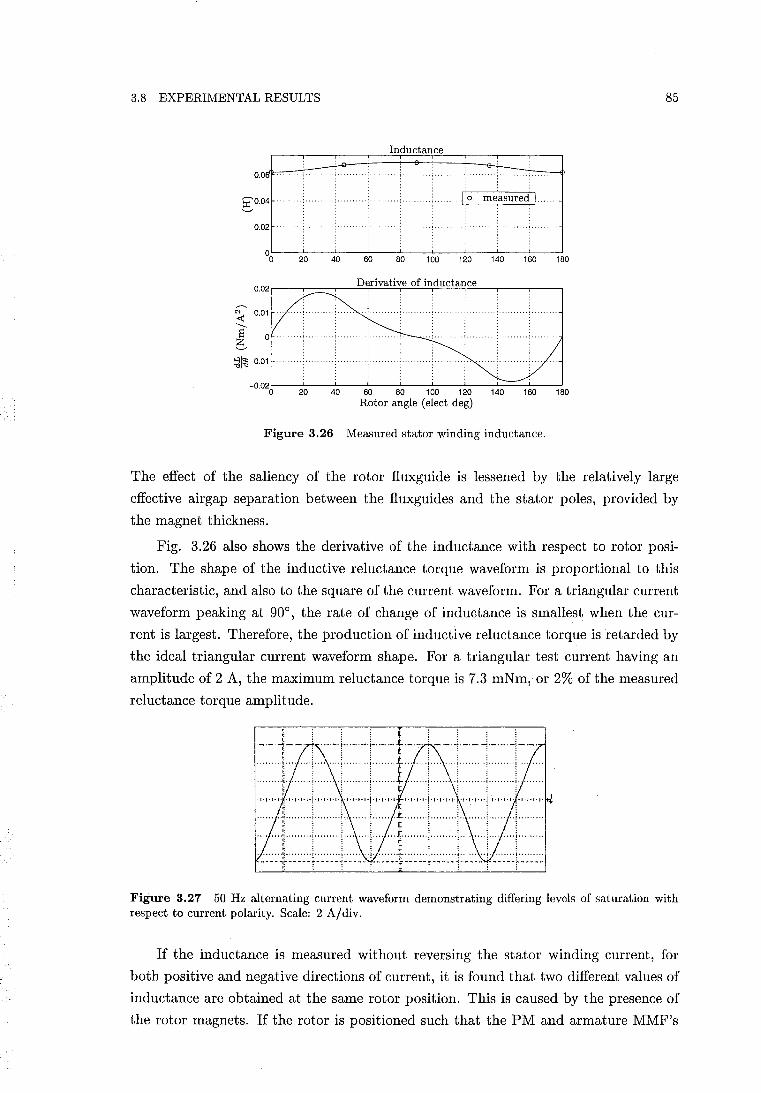
3.8 EXPERIMENTAL RESULTS 85
Inductance
0.0
gO.04
~L---L---~--~--~---100L---L---~--~--~180
:;1~-0.01
Figure 3.26 Measured stator winding inductance.
The effect of the saliency of the rotor fluxguide is lessened by the relatively large
effective airgap separation between the fluxguides and the stator poles, provided by
the magnet thickness.
Fig. 3.26 also shows the derivative of the inductance with respect to rotor posi
tion. The shape of the inductive reluctance torque waveform is proportional to this
characteristic, and also to the square of the current waveform. For a triangular current
waveform peaking at 90°, the rate of change of inductance is smallest when the cur
rent is largest. Therefore, the production of inductive reluctance torque is retarded by
the ideal triangular current waveform shape. For a triangular test current having an
amplitude of 2 A, the maximum reluctance torque is 7.3 mNm, or 2% of the measured
reluctance torque amplitude.
Figure 3.27 50 Hz alternating current waveform demonstrating differing levels of saturation with respect to current polarity. Scale: 2 A/div.
If the inductance is measured without reversing the stator winding current, for
both positive and negative directions of current, it is found that two different values of
inductance are obtained at the same rotor position. This is caused by the presence of
the rotor magnets. If the rotor is positioned such that the PM and armature MMF's
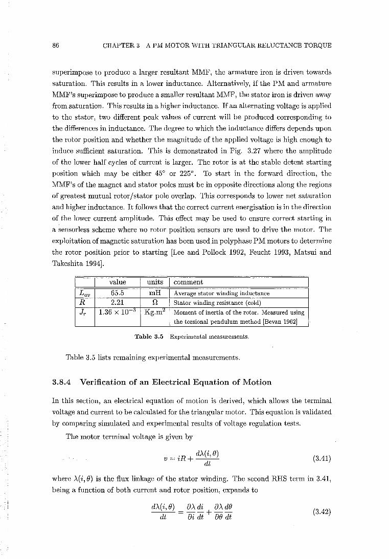
86 CHAPTER 3 A PM MOTOR WITH TRIANGULAR RELUCTANCE TORQUE
superimpose to produce a larger resultant MMF, the armature iron is driven towards
saturation. This results in a lower inductance. Alternatively, if the PM and armature
MMF's superimpose to produce a smaller resultant MMF, the stator iron is driven away
from saturation. This results in a higher inductance. If an alternating voltage is applied
to the stator, two different peak values of current will be produced corresponding to
the differences in inductance. The degree to which the inductance differs depends upon
the rotor position and whether the magnitude of the applied voltage is high enough to
induce sufficient saturation. This is demonstrated in Fig. 3.27 where the amplitude
of the lower half cycles of current is larger. The rotor is at the stable detent starting
position which may be either 45° or 225°. To start in the forward direction, the
MMF's of the magnet and stator poles must be in opposite directions along the regions
of greatest mutual rotor/stator pole overlap. This corresponds to lower net saturation
and higher inductance. It follows that the correct current energisation is in the direction
of the lower current amplitude. This effect may be used to ensure correct starting in
a sensorless scheme where no rotor position sensors are used to drive the motor. The
exploitation of magnetic saturation has been used in polyphase PM motors to determine
the rotor position prior to starting [Lee and Pollock 1992, Feucht 1993, Matsui and
Takeshita 1994].
value units comment
Lav 65.5 mH Average stator winding inductance
R 2.21 n Stator winding resistance (cold)
Jr 1.36 X 10⁻³ Kg.m:4 Moment of inertia of the rotor. Measured using
the torsional pendulum method [Bevan 1962]
Table 3.5 Experimental measurements.
Table 3.5 lists remaining experimental measurements.
3.8.4 Verification of an Electrical Equation of Motion
In this section, an electrical equation of motion is derived, which allows the terminal
voltage and current to be calculated for the triangular motor. This equation is validated
by comparing simulated and experimental results of voltage regulation tests.
The motor terminal voltage is given by
'R d)..(i, 0) v = 2 + --':-'-...:... dt
(3.41)
where )"(i, 0) is the flux linkage of the stator winding. The second RHS term in 3.41,
being a function of both current and rotor position, expands to
d)..(i,O) 0).. di 0).. dO dt = oi dt + 00 dt
(3.42)
3.8 EXPERIMENTAL RESULTS 87
In the absence of iron saturation, or if the saturation is constant, the flux linkage may
be given by eqn. 2.61:
Substitution of eqn. 2.61 into 3.42 yields
(3.43)
Since Am and L have not been defined to be functions of i in eqn. 2.61, 8Am /8i becomes
zero, and the remaining partial derivatives become derivatives of a single variable. Eqn.
3.41 then becomes
(3.44)
where e = de / dt. The second RHS term of eqn. 3.44 is the EMF, e, induced by the
field of the magnets. The third and fourth RHS terms represent induced EMF's due
to the self-induction of the stator winding, referred to respectively as the transformer
and speed voltages [Woodson and Melcher 1968, pp. 19-20].
For generation, the terminal voltage is equal to the voltage across the electrical
load. For a purely resistive load, v = iRz, where Rl is the resistive load. The EMF
induced by the magnets, e = d~r e, energises the armature and the load. To simulate
generation under a resistive load, eqn. 3.44 is presented in state equation form:
(3.45)
where the variables describing the state of the system are i and e. Eqn. 3.45 is
a nonlinear ordinary differential equation because L(e), d~lf', and ~~ are nonlinear
functions. The shaft speed is held constant for generation, and e is obtained from the
state equation given by
de . dt = e = constant (3.46)
Eqn.s 3.45 and 3.46 form a set of equations which must be solved numerically. The
simulations are performed using the SIMNON simulation package [Elmqvist et al. 1990],
which applies the Runge-Kutta-Fehlberg integration method. L(e) and ~~ are modelled
using the measured waveforms of Fig. 3.26. d~r is modelled using the measured
waveform of Fig. 3.18. The value of R given in Table 3.5 is used.
Voltage regulation tests were performed running the triangular motor as a generator
under constant speed, using a resistive load. Under no load, the terminal voltage
waveform is simply the induced EMF, e = d~O e, shown in Fig. 3.18. With a load across
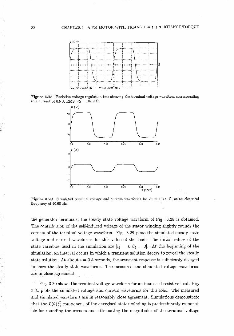
88 CHAPTER 3 A PM MOTOR WITH TRIANGULAR RELUCTANCE TORQUE
20.0V
-.--.-=~ ......... ! ........ ~ ••••••• 1.. .... j, ........ ! ....... .. ....... j ········i .. , .. of .. · .. '''!'' ·······1 ... ( . . . . ~ . . . . . , . . ,
"'j ••••• ··i ... , ······'·1 ........ ; "'!'" .j",j,t,j·,·",.,.'·,.,,·,·!,,·,·,·,·I·,·,·,·, I"""'!""""'!"'II"'!""'I"'!"'I'I'" . . ,: i j : '
..•.. ! .. ! . . . . . . . ..... ~ . .. . .. . .. .. ! ......... i ....... . ! ......... i . ~ . . . . . , . i
·····,···j······,,·l····· 1······, ..
Freq( 1)=40 .08 Hz Vrms( D=53 .96 V
Figure 3.28 Resistive voltage regulation test showing the terminal voltage waveform corresponding to a current of 0.5 ARMS. Rl = 107.9 n.
v (V)
-50
0.4 0.41 0.42 0.43 0.44 0.45
i (A) 2
-2
0.4 0.41 0.42 0.43 0.44 0.45 . t (sees)
Figure 3.29 Simulated terminal voltage and current waveforms for Rl = 107.9 n, at an electrical frequency of 40.08 Hz.
the generator terminals, the steady state voltage waveform of Fig. 3.28 is obtained.
The contribution of the self-induced voltage of the stator winding slightly rounds the
corners of the terminal voltage waveform. Fig. 3.29 plots the simulated steady state
voltage and current waveforms for this value of the load. The initial values of the
state variables used in the simulation are [i0 = 0,80 = OJ. At the beginning of the
simulation, an interval occurs in which a transient solution decays to reveal the steady
state solution. At about t = 0.4 seconds, the transient response is sufficiently decayed
to show the steady state waveforms. The measured and simulated voltage waveforms
are in close agreement.
Fig. 3.30 shows the terminal voltage waveform for an increased resistive load. Fig.
3.31 plots the simulated voltage and current waveforms for this load. The measured
and simulated waveforms are in reasonably close agreement. Simulations demonstrate
that the L(8)* component of the energised stator winding is predominantly responsi
ble for rounding the corners and attenuating the magnitudes of the terminal voltage
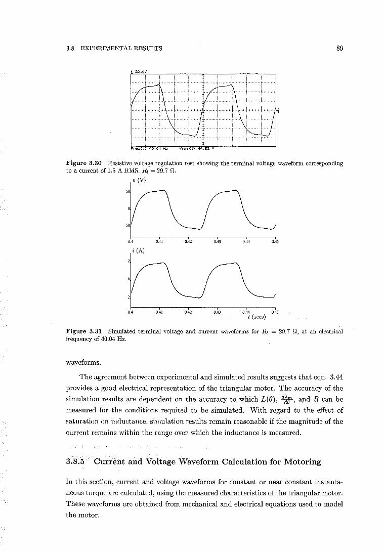
3.8 EXPERIMENTAL RESULTS 89
20.0\1
. .. , ... , .... ,. i,.· .... ,.
......... : ....... i·· .. •• ...... ··..:-· .... ·t ...... .. : + : . ·····1.·· ..... 0+- ....... ,."
• ... y ......... ......... j ........ .
; t ....... "'~"""" ....... ,.! ..
""""'!""""'i'"''
•..• ~ •• . ••••• 1 ' • . .........!....
' ........ i·· ...... ; .. . . ...•. 4- •• , .....
FreqC 1)=40.04 H~ Vrms(\)=44.62 \I
Figure 3.30 Resistive voltage regulation test showing the terminal voltage waveform corresponding to a current of 1.5 ARMS. Rl = 29.7 n.
v (V)
50
-50
0.4 0.41 0.42 0.43 0.44 0.45
i (A)
-2
0.4 0.41 0.42 0.43 . 0.44 0.45 t (sees)
Figure 3.31 Simulated terminal voltage and current waveforms for Rl = 29.7 n, at an electrical frequency of 40.04 Hz.
waveforms.
The agreement between experimental and simulated results suggests that eqn. 3.44
provides a good electrical representation of the triangular motor. The accuracy of the
simulation results are dependent on the accuracy to which L(e), d~1t, and R can be
measured for the conditions required to be simulated. With regard to the effect of
saturation on inductance, simulation results remain reasonable if the magnitude of the
current remains within the range over which the inductance is measured.
3.8.5 Current and Voltage Waveform Calculation for Motoring
In this section, current and voltage waveforms for constant or near constant instanta
neous torque are calculated, using the measured characteristics of the triangular motor.
These waveforms are obtained from mechanical and electrical equations used to model
the motor.
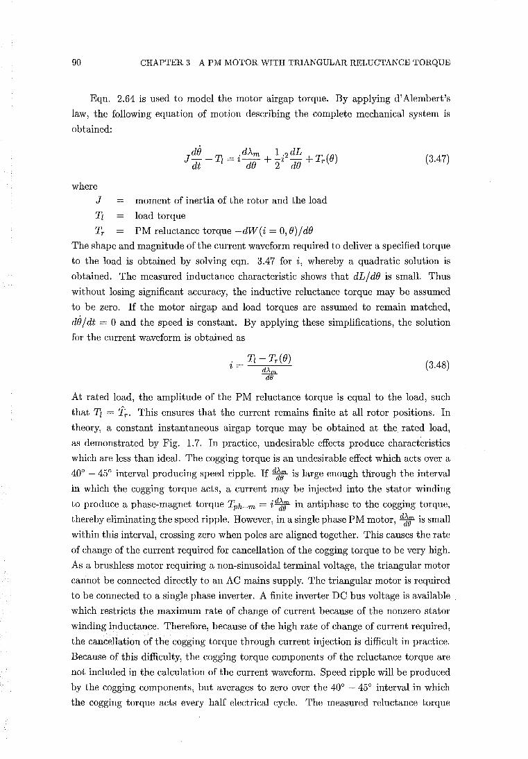
90 CHAPTER 3 A PM MOTOR WITH TRIANGULAR RELUCTANCE TORQUE
Eqn. 2.64 is used to model the motor airgap torque. By applying d'Alembert's
law, the following equation of motion describing the complete mechanical system is
obtained:
(3.47)
where
J moment of inertia of the rotor and the load
Tz load torque
Tr PM reluctance torque -dW(i = 0, B)/dB
The shape and magnitude of the current waveform required to deliver a specified torque
to the load is obtained by solving eqn. 3.47 for i, whereby a quadratic solution is
obtained. The measured inductance characteristic shows that dL/dB is small. Thus
without losing significant accuracy, the inductive reluctance torque may be assumed
to be zero. If the motor airgap and load torques are assumed to remain matched,
de / dt = 0 and the speed is constant. By applying these simplifications, the solution
for the current waveform is obtained as
(3.48)
At rated load, the amplitude of the PM reluctance torque is equal to the load, such
that Tz = 'ir . This ensures that the current remains finite at all rotor positions. In
theory, a constant instantaneous airgap torque may be obtained at the. rated load,
as demonstrated by Fig. 1.7. In practice, undesirable effects produce characteristics
which are less than ideal. The cogging torque is an undesirable effect which acts over a
40° - 45° interval producing speed ripple. If d~lJ' is large enough through the interval
in which the cogging torque acts, a current may be injected into the stator winding
to produce a phase-magnet torque Tph-m = id~r in antiphase to the cogging torque,
thereby eliminating the speed ripple. However, in a single phase PM motor, d~r is small
within this interval, crossing zero when poles are aligned together. This causes the rate
of change of the current required for cancellation of the cogging torque to be very high.
As a brushless motor requiring a non-sinusoidal terminal voltage, the triangular motor
cannot be connected directly to an AC mains supply. The triangular motor is required
to be connected to a single phase inverter. A finite inverter DC bus voltage is available
which restricts the maximum rate of change of current because of the nonzero stator
winding inductance. Therefore, because of the high rate of change of current required,
the cancellation of the cogging torque through current injection is difficult in practice.
Because of this difficulty, the cogging torque components of the reluctance torque are
not included in the calculation of the current waveform. Speed ripple will be produced
by the cogging components, but averages to zero over the 40° - 45° interval in which
the cogging torque acts every half electrical cycle. The measured reluctance torque
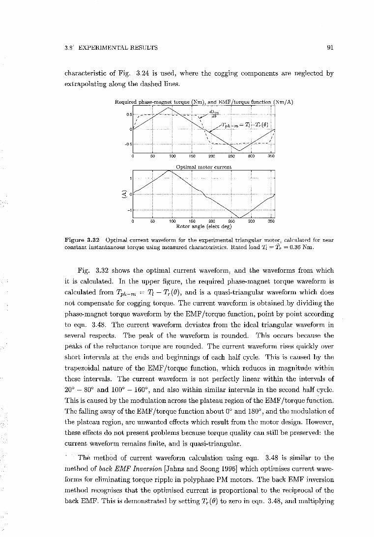
3.8) EXPERIMENTAL RESULTS 91
characteristic of Fig. 3.24 is used, where the cogging components are neglected by
extrapolating along the dashed lines.
Required phase-magnet torque (Nm), and EMF/torque function (Nm/A)
0.5
o
o 50
· . . Tph~m.~'I'I~'I'r.(e) ..
· . · . · . · . · . ..;....- . ...,..~.-:-..
250 300
100 150 200 250 300 Rotor angle (elect deg)
:, 1
" 350
350
Figure 3.32 Optimal current waveform for the experimental triangular motor, calculated for near constant instantaneous torque using measured characteristics. Rated load Tl = Tr = 0.36 Nm.
Fig. 3.32 shows the optimal current waveform, and the waveforms from which
it is calculated. In the upper figure, the required phase-magnet torque waveform is
calculated from Tph-m = Tz - Tr(B), and is a quasi-triangular waveform which does
not compensate for cogging torque. The current waveform is obtained by dividing the
phase-magnet torque waveform by the EMF/torque function, point by point according
to eqn. 3.48. The current waveform deviates from the ideal triangular waveform in
several respects. The peak of the waveform is rounded. This occurs because the
peaks of the reluctance torque are rounded. The current waveform rises quickly over
short intervals at the ends and beginnings of each half cycle. This is caused by the
trapezoidal nature of the EMF/torque function, which reduces in magnitude within
these intervals. The current waveform is not perfectly linear within the intervals of
20° - 80° and 100° - 160°, and also within similar intervals in the second half cycle.
This is caused by the modulation across the plateau region of the EMF/torque function.
The falling away of the EMF/torque function about 0° and 180° , and the modulation of
the plateau region, are unwanted effects which result from the motor design. However,
these effects do not present problems because torque quality can still be preserved: the
current waveform remains finite, and is quasi-triangular.
The method of current waveform calculation using eqn. 3.48 is similar to the
method of back EMF Inversion [Jahns and Soong 1996] which optimises current wave
forms for eliminating torque ripple in polyphase PM motors. The back EMF inversion
method recognises that the optimised current is proportional to the reciprocal of the
back EMF. This is demonstrated by setting Tr(B) to zero in eqn. 3.48, and multiplying
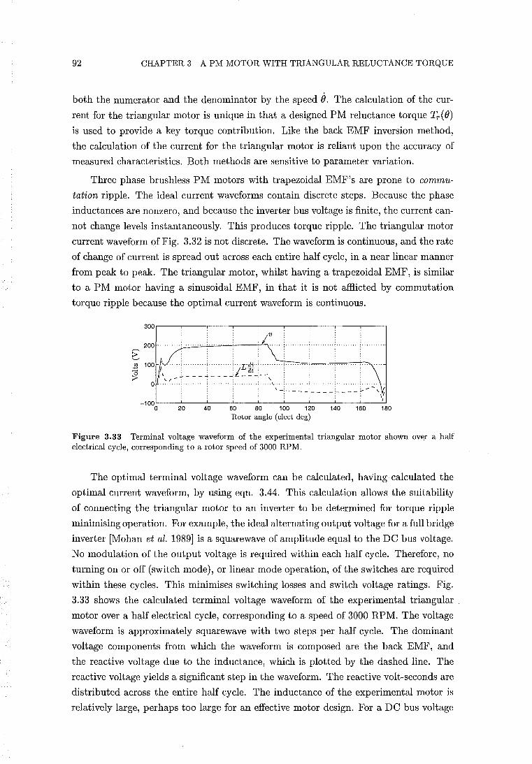
92 CHAPTER 3 A PM MOTOR WITH TRIANGULAR RELUCTANCE TORQUE
both the numerator and the denominator by the speed (). The calculation of the cur
rent for the triangular motor is unique in that a designed PM reluctance torque Tr (())
is used to provide a key torque contribution. Like the back EMF inversion method,
the calculation of the current for the triangular motor is reliant upon the accuracy of
measured characteristics. Both methods are sensitive to parameter variation.
Three phase brushless PM motors with trapezoidal EMF's are prone to commu
tation ripple. The ideal current waveforms contain discrete steps. Because the phase
inductances are nonzero, and because the inverter bus voltage is finite, the current can
not change levels instantaneously. This produces torque ripple. The triangular motor
current waveform of Fig. 3.32 is not discrete. The waveform is continuous, and the rate
of change of current is spread out across each entire half cycle, in a near linear manner
from peak to peak. The triangular motor, whilst having a trapezoidal EMF, is similar
to a PM motor having a sinusoidal EMF, in that it is not afflicted by commutation
torque ripple because the optimal current waveform is continuous.
300
200
~ <J.l
;!::;
~
-100 0 20 60 80 100 120 140 160 180
Rotor angle (elect deg)
Figure 3.33 Terminal voltage waveform of the experimental triangular motor shown .over a half electrical cycle, corresponding to a rotor speed of 3000 RPM.
The optimal terminal voltage waveform can be calculated, having calculated the
optimal current waveform, by using eqn. 3.44. This calculation allows the suitability
of connecting the triangular motor to an inverter to be determined for torque ripple
minimising operation. For example, the ideal alternating output voltage for a full bridge
inverter [Mohan et al. 1989] is a squarewave of amplitude equal to the DC bus voltage.
No modulation of the output voltage is required within each half cycle. Therefore, no
turning on or off (switch mode), or linear mode operation, of the switches are required
within these cycles. This minimises switching losses and switch voltage ratings. Fig.
3.33 shows the calculated terminal voltage waveform of the experimental triangular
motor over a half electrical cycle, corresponding to a speed of 3000 RPM. The voltage
waveform is approximately squarewave with two steps per half cycle. The dominant
voltage components from which the waveform is composed are the back EMF, and
the reactive voltage due to the inductance, which is plotted by the dashed line. The
reactive voltage yields a significant step in the waveform. The reactive volt-seconds are
distributed across the entire half cycle. The inductance of the experimental motor is
relatively large, perhaps too large for an effective motor design. For a DC bus voltage
3.9 CONCLUSIONS 93
of approximately 200 V, the optimal torque ripple minimising voltage and current
waveforms can be achieved. For a hypothetical three phase brushless motor of similar
rotor design having similar values of per phase inductance, significant commutation
ripple is likely to result. In order for the current to change levels quickly to maintain
reasonable torque quality, similar reactive volt-seconds are required to be distributed
over much shorter intervals. In this case, a higher DC bus voltage would be required
to accommodate the volt-sconds.
A triangular motor drive consisting of a current regulated inverter, and a current
reference waveform generator, is recommended. The current reference generator uses
eqn. 3.48 to convert the required torque into a current reference. This scheme does not
require calculation of the terminal voltage, as in the case of a voltage regulated inverter,
and is thus not prone to further errors created by the measurement or estimation of
the electrical equation parameters. Rotor position feedback is required to synchronise i
and e. The selection of the type of rotor position sensors is dependent on the required
resolution. This, in turn, is dependent on the required quality of the torque. For a
basic position sensing scheme, a Hall effect sensor is required to detect the rotor position
every half electrical cycle where the current changes direction. A second sensor may
also be required to detect rotor position at the middle of every half electrical cycle,
where the current peaks.
3.9 CONCLUSIONS
This chapter has provided two contributions: the first is the description of an analytical
method of calculating PM reluctance torque; the second is the examination of the
triangular motor concept.
The analytical method of calculating PM reluctance torque uses an elementary
expression for the magnetic field to obtain the stored energy. It is shown that the
method does not require the magnetic field to be accurately resolved into its normal
and tangential components, unlike the Maxwell stress method where similar approx
imation is intolerable. This allows the use of an elementary expression for the field.
Because the stored energy is an analytical expression, the error in taking the deriva
tive with respect to rotational displacement to obtain the torque is zero. The method
has been demonstrated to provide a powerful and fast design tool. The method can be
generally applied to reluctance torque problems where the airgap is reasonably smooth.
Further examples of the application of the method are found in the paper 'Effects of
Airgap and Magnet Shapes on Permanent Magnet Reluctance Torque' in Appendix
A, and in Chapter 4. However, application of the method is likely to exclude cogging
torque problems due to stator slotting because the field is unlikely to be described with
sufficient accuracy.
An experimental motor has been built to verify the concept of the triangular motor.
94 CHAPTER 3 A PM MOTOR WITH TRIANGULAR RELUCTANCE TORQUE
This requires the implementation of an ideally square-wave EMF/torque function, and
a triangular PM reluctance torque waveform. It is shown that the implementation of
each of these characteristics requires conflicting PM pole pitches. Full pitched poles
are required for the desired EMF/torque function, and poles of half an electrical pitch
are required for the production of the triangular reluctance torque. To successfully
accommodate both of these characteristics using a single magnetic circuit, a double set
of airgaps, and the magnet/iron flux guide rotor construction, have been implemented.
Unwanted effects are shown to be present in the measurements of these character
istics. The EMF/torque function is trapezoidal in shape, rather than squarewave. The
plateau region of the EMF /torque function is shown to be modulated by the triangular
modulation of the reluctance airgap. The PM reluctance torque is triangular in shape,
but has cogging torque components due to stator slotting superimposed upon it. The
non ideal characteristics of the EMF/torque function are shown not to create signif
icant difficulty, in that the optimal current waveform calculated using the measured
characteristics remains quasi-triangular, or close to the ideal triangular waveform. The
cogging torque is shown to be difficult to eliminate, but it is noted that the cogging
torque acts over only a short interval of every half electrical cycle. The experimen
tal results demonstrate that the required EMF/torque function and reluctance torque
characteristics can be adequately implemented in a real motor. This demonstrates that
it is possible to produce a high quality torque in a brushless single phase PM motor.
The concept of the magnetic reluctance circuit has been used to model the tri
angular motor. Both the PM reluctance torque and the EMF/torque function are
successfully modelled using a simple reluctance circuit model. The results of the model
are supported by results obtained using finite element analysis. The measured ampli
tude of the PM reluctance torque is significantly lower than the value estimated using
the methods described above. This was found to be caused by ferromagnetism in the
stainless steel structure supporting the rotor poles. Even though the permeability of
the stainless steel was shown to be low, the reluctance circuit model demonstrates that
the reluctance torque is sensitive to the permeability, or effective interpolar distance,
between the iron flux guides of the rotor.
The axial flux construction, employing double rotor airgaps and concentrically
wound laminations, made the experimental motor difficult to build. Whilst serving
the purpose of demonstrating the triangular motor concept, the experimental design is
unlikely to be manufacturable for any other purpose. As a brushless PM motor which
cannot be connected directly to an AC supply, an electronic drive is required: an in
verter is necessary to inject the required triangular current into the stator winding; and
rotor position sensing is required to maintain synchronism. The need for an electronic
drive increases the cost and complexity of the motor. The performance of the motor is
limited. The triangular motor is not designed to run in the reverse direction because
the PM reluctance and phase-magnet torques superimpose to yield a large pulsating
3.9 CONCLUSIONS 95
torque. For rotation in the forward direction, torque ripple results if the load torque
is not equal to the amplitude of the PM reluctance torque. For example, for rotor
positions of stator and rotor pole alignment (00 or 1800), the triangular PM reluctance
torque is the only motor airgap torque acting. At these positions the magnitude of
the reluctance torque is equal to its amplitude. If the magnitude of the load is not
the same, acceleration must occur at these positions. The amplitude of the reluctance
torque remains fixed, and cannot be adjusted to match the load. The amount of accel
eration occurring at these positions is proportional to the difference between the two
torques. At other rotor positions, it is possible to match the load torque by injection of
the appropriate current to modulate the phase-magnet torque as required. This, how
ever, increases the complexity of the controller, and requires high resolution position
sensing.
In contrast, three-phase brushless PM motors have similar drive complexity, but in
addition offer reversibility and a wider torque-speed range. Therefore, the triangular
motor is unlikely to be able compete in general brushless PM motor applications. If an
application is to be proposed for the triangular motor, it must be one that only requires
capabilities that the triangular motor can perform well. Performance requirements
must still remain high, or else cheaper motors which do not require drives such as single
phase induction motors, could be used. A computer hard disk drive motor [Jabbar
et al. 1992] is a possible application. Three phase brushless PM motors with electronic
drives are generally used in this application. The application requires rotation in one
direction only, the running load torque and speed remain fixed, and a high quality motor
torque is required. These performance requirements are met by the triangular motor,
but a manufacturable design is required. A radial flux design having a single airgap
has been proposed for this purpose. A single phase triangular motor design has both
advantages and disadvantages in comparison to the conventional three-phase motor
designs. For such an application, a large number of issues are required to be considered
in comparing the proposed motor and existing three-phase disk drive motors.

Chapter 4
THE UNIDIRECTIONAL SINGLE PHASE SYNCHRONOUS PM MOTOR
4.1 INTRODUCTION
This chapter examines in more detail the concept of the unidirectional motor introduced
in section 1.4. Like the motor tested in the Chapter 3, the unidirectional motor also uses
PM reluctance torque to obtain constant instantaneous torque. However, in contrast
the unidirectional motor employs a sinusoidal back EMF and sinusoidal PM reluctance
torque. This chapter covers the theoretical development of the unidirectional motor.
The scope of this development is to produce two 'ballpark' designs which provide a
starting point for experimental investigation.
4.2 THEORY OF THE SINGLE PHASE SYNCHRONOUS PM MOTOR
This section reviews a selection of equations and characteristics corresponding to the
conventional single phase synchronous PM motor. Conventional is used in this context
to mean the common designs demonstrated, for example, by Fig.s 1.1 and 1.2. The
final direction of rotation is not predetermined for the conventional motors. Much of
the material in the review is based on the thesis of [Schemmann 1971], but all the
equations are extended from the single pole pair case to an arbitrary number of pole
pairs.
The unidirectional motor is designed to operate at a specific mechanical loading
associated with a specific load angle under synchronous operation. This specific load
angle corresponds to the EMF/torque function and the current being in phase with
each other. The load angle is defined later in this section. However, the load angle
varies as a function of mechanical loading. Therefore, if the load deviates from the ideal
value, the load angle of the unidirectional motor also deviates from the design value.
The conventional theory provides for a variable load, and thus an arbitrary load angle.
In respect to load angle, the unidirectional motor loading may be described as a single
98 CHAPTER 4 THE UNIDIRECTIONAL SINGLE PHASE SYNCHRONOUS PM MOTOR
and special example within the wider range of conventional motor loading. Therefore
the conventional theory can provide a general framework in which the unidirectional
motor may be analysed. As such, this review of the conventional motor is important
because its equations and characteristics are also applicable to the unidirectional motor.
The PM flux linkage of single pole pair and multiple pole pair single phase mo
tors is determined in section 4.7. In this present section, the PM flux linkage, or its
fundamental component at least, is assumed to be given by
(4.1)
where
~m peak PM flux linkage (flux-turns)
p number of pole pairs
e mechanical rotor angle
The EMF/torque function is then given by
(4.2)
and the induced EMF is given by
(4.3)
where e = de / dt is the instantaneous mechanical angular rotor speed.
The following analysis corresponds to perfect synchronous motion in which the
speed ripple is zero and the instantaneous speed e is constant. The electrical rotor
angle may therefore be expressed by
(4.4)
where e~ is the electrical rotor angle at t = O.
Furthermore, the mechanical rotor speed and the electrical angular speed, We, are
related by
(4.5)
Substitution of eqn.s 4.4 and 4.5 into eqn. 4.3 yields the synchronous EMF:
(4.6)
4.2 THEORY OF THE SINGLE PHASE SYNCHRONOUS PM MOTOR 99
The current may be obtained from:
. v sin(wet + E - a) - We>-m sin(wet + e~ - a) 2 = ------''----'-----'-------=--...:..:..:...--'-----=---.:....
Z (4.7)
where a = arctan(weL/ R), and Z is given by eqn. 1.14.
The peak value of the induced EMF is given by
(4.8)
If E is set to zero, comparison of the voltage terms in eqn. 4.7 show that e~ then gives
the phase angle between v and e. eo will be defined to be the angle between v and e with E = O. The current may then be expressed by
where cp is the phase angle between v and i l .
The average torque produced by the motor is given by
where T is the electrical period.
T - 1/7 .dAmd - - 2-- t T de
(4.9)
(4.10)
Substitution of eqn.s 4.2 and 4.7 into eqn. 4.10 with E = 0 and pe = wet +eo yields
(4.11)
Eqn. 4.11 shows that the average torque is composed of two components: one which
varies as a sinusoidal function of eo, and another which is constant and negative. The
torque cannot be controlled by adjusting A~ because the PM excitation is fixed. The
motor torque is determined by the mechanical load, and eo will thus be referred to
as the load angle. The winding resistance of single phase synchronous PM motors is
relatively large and cannot be neglected in the calculation of torque. The torque cannot
be approximated to be a linear function of eo for small load angles where a is not large.
This differs from three phase synchronous machines where the winding resistance is
relatively small, and a approaches 900• In this case, with a large value of a, eqn. 4.11
simplifies to a single term where the torque is proportional to - sin eo.
Positive (motoring) pullout torque occurs when cos(a+eo ) = 1. The pullout torque
is given by
THE LIBRARY UNIVERSITY OF CANTERBURY
CHRISTCHURCH, N.Z.
(4.12)
100 CHAPTER 4 THE UNIDIRECTIONAL SINGLE PHASE SYNCHRONOUS PM MOTOR
and the corresponding load angle is
(4.13)
If bearing friction and windage are ignored, the average output power and pullout
power may be obtained by multiplying eqn.s 4.11 and 4.12 by 0, respectively. Output
power may be expressed as
ev e2
Pout = 2Z cos(a + 00 ) - 2Z cos a
The input power is obtained from
1 JT Pin = -:;. vi dt
Substitution of eqn.s 1.6 and 4.9 into 4.15 yields
The efficiency is then given by
Pout ev cos(a + 00 ) - e2 cos a 'T}----
- Pin -- V2 cos a - ev cos(a - 00 )
The maximum efficiency [Schemmann 1971, p. 28] is given by
( e / v) cos a + 1 e 'T}max = (A/A) + -:::-, e v cosa v
and the corresponding value of 00 is given by
e -<1 v -
( 0) 1 - 'T}max
tan - 0 = 1 tan a +'T}max
4.2.1 Unperturbed Motion
(4.14)
(4.15)
(4.16)
(4.17)
(4.18)
(4.19)
In practice, speed ripple about the mean synchronous value is characteristic of single
phase synchronous PM motors. The motion of the motor is governed by eqn.s 1.5
and 1. 7. These are a set of nonlinear differential equations which are not integrable in
closed form [Bertram and Schemmann 1976]. However, approximate solutions to the
synchronous motion may be obtained without fully solving these equations.
By applying the method of successive approximation, an unperturbed solution of
the differential equations may be obtained. The unperturbed motion is characterised
by a nearly sinusoidal current with a synchronous speed modulated at twice the elec
trical frequency. A detailed derivation of the unperturbed solution is given in [Schem-
4.2 THEORY OF THE SINGLE PHASE SYNCHRONOUS PM MOTOR 101
mann 1971, pp. 21-25]. A shortened description of this derivation is given in this
section. The solution is extended to include an arbitrary number of pole pairs.
A first approximation of the current is provided by eqn. 4.9. By assuming the
instantaneous speed to be constant as a first approximation, the instantaneous torque
produced by the motor is obtained by the product of eqn.s 4.9 and 4.2, with p() =
wet + ()o:
(4.20)
For convenience, the no load case is obtained. Substitution of cp = 37r /2 + ()o into eqn.
4.20 yields the no load torque:
(4.21)
With reference to eqn. 4.53, with the load torque Tz set to zero, the mechanical angular
acceleration is obtained as
(4.22)
In eqn. 4.22, the acceleration is the result of contributions from both the phase-magnet
torque and the PM reluctance torque. Wr is the amplitude of stored energy modulation
when the current is zero. Generally "'Ir is small, and a reasonably accurate simplification
of eqn. 4.22 is achieved by setting "'Ir = O. Application of this simplification followed
by integration with respect to time yields the following speed modulation:
(4.23)
The amplitude of the speed modulation may be normalised as follows:
(4.24)
Eqn. 4.24 shows that increasing the number of pole pairs exacerbates the speed ripple.
An improved approximation of the speed is obtained by
(4.25)
Integration of the speed yields an improved approximation of the rotor position. The
improved approximations of speed and position allow a more complicated approxima
tion of the induced EMF to be obtained. A further approximation of the current is
then obtained by a calculation similar to eqn. 4.9. Odd current harmonics are obtained
102 CHAPTER 4 THE UNIDIRECTIONAL SINGLE PHASE SYNCHRONOUS PM MOTOR
yielding
(4.26)
Expressions for the amplitudes of the harmonic currents show that the higher order
harmonics are very small. This is supported by the steady state water-pumping test
results of the Siemens motor presented in section 5.5.4.3. In these test results, current
harmonics above the third are negligible.
Use of eqn. 4.26 allows further improved approximation of the acceleration and
speed to be obtained. Even speed harmonics are found. The fourth harmonic is rela
tively small and may be neglected. Schemmann describes eqn.s 4.25 and 4.26 as good
approximations. These equations are defined as the unperturbed solutions to the dif
ferential equations. Single phase synchronous PM motors are designed to exhibit the
unperturbed motion during running [Schemmann 1973]. The unperturbed motion must
be maintained within the expected spread of the parameters of the motor.
4.2.2 Perturbed Motion
Other harmonic solutions are also shown to exist for synchronous motion. Other har
monic solutions for the rotor speed are derived in [Schemmann 1971] and [Schem
mann 1973]. These solutions are described in this section.
For synchronous motion, the average speed of the rotor must correspond to the
angular speed of the electrical supply in accordance with eqn. 4.5. This means that
the speed variations over a long time must be zero. Periodic speed variations may be
written as the sum of a number of simple harmonic motions given by
n
pO-we = LAvsin(avwet+'l/Jv) ( 4.27) v=1
The integral of each harmonic averages to zero over a time extending the period, Tv, of
each harmonic. This is expressed mathematically by
(4.28)
For the unperturbed motion described by eqn. 4.25, the harmonic has a frequency
exactly double that of the electrical frequency. The period of this harmonic may be
written as Tl = 1r/we . Subharmonic possibilities may occur when the period is an
integral multiple of Tl, such that Tv = kTl = k1r /we , where k = 1,2,3 .... The integral
may be rewritten as
(4.29)
4.3 STEADY STATE THEORY OF THE UNIDIRECTIONAL MOTOR 103
which evaluates to
(4.30)
Eqn. 4.30 is satisfied if av = 2v/k, where v = 1,2,3, .... The following values may
therefore be calculated for av :
k=l a1 = 2, a2 = 4, a3 = 6, .,.
k=2 a1 = 1, a2 = 2, a3 = 3, ...
k=3 a1 = 2/3, a2 = 4/3, a3 = 6/3, ...
Values of av for higher values of k may also be calculated. Substitution of the values
of av corresponding to k = 1 into eqn. 4.27 yields the unperturbed motion:
(4.31)
Larger values of k describe what are referred to as periodic perturbed motions. For
k = 2, for a 50 Hz supply frequency, there is a 50 Hz perturbation:
(4.32)
Likewise, k = 3 yields a 331 Hz perturbation:
pO = We + C1 sin(2/3wet + "Y1) + C2 sin(4/3wet + ')'2) + C3 sin(6/3wet + ')'3) + ... (4.33)
These perturbations are illustrated in Table 1.1. Perturbations are possible for larger
values of k resulting in more complicated motion. Schemmann describes these per
turbed motions as subharmonic resonances of a periodic driving torque with a fre
quency equal to twice the electrical frequency. This torque occurs due to the backward
field which rotates around the surface of the rotor at this frequency.
The unidirectional motor presents a special case where, under appropriate con
ditions, the PM reluctance torque cancels out the torque modulation created by the
backward rotating field. The instantaneous motor torque is constant and the speed
ripple is zero. In this case, the synchronous motion is simply described by
4.3 STEADY STATE THEORY OF THE UNIDIRECTIONAL MOTOR
In this section, the theory introduced in section 1.3.2 is extended. Equations spe
cific to the unidirectional motor are developed corresponding to running at constant
instantaneous synchronous speed.
104 CHAPTER 4 THE UNIDIRECTIONAL SINGLE PHASE SYNCHRONOUS PM MOTOR
For a unidirectional motor having p pole pairs, the instantaneous current required
is obtained as a function of the torque requirement from eqn. 4.53. For zero mechanical
angular acceleration, the current is given by
. Tz + 2p Wr sin[2p( () - "Ir )] ~ = ~
pAm sin(p()) (4.34)
For forward rotation, the PM reluctance displacement angle is set to P"lr = 45° (electrical).
To allow constant instantaneous torque to be applied to the load, the magnitude of the
load torque is set to the amplitude of the PM reluctance torque:
(4.35)
The required current is then obtained as a function of the rotor position by
. 4Wr . ( ()) ~ = -~-smp
Am (4.36)
where the amplitude of the current is i = 4 Wr / ),m. Substitution of Wr = T /2p into
this expression for i gives an alternative equation for the unidirectional motor torque:
(4.37)
Comparison of eqn.s 4.3 and 4.36 shows that the current and induced EMF are in
phase. The phase angle between the current and the supply voltage is therefore the
same as the angle between the induced EMF and the supply voltage, such that r.p = ()o.
For synchronous motion, with € = 0 and p() = wet + ()o, the current may be given by
(4.38)
The instantaneous terminal voltage of the motor is given by
v = L di / dt + iR + e (4.39)
Substitution of eqn. 4.38 and its derivative with respect to time, as well as eqn.s 1.6
and 4.6, into 4.39, with € = 0 yields
(4.40)
Eqn. 4.40 shows that the terminal voltage is the sum of orthogonal components. There-
4.3 STEADY STATE THEORY OF THE UNIDIRECTIONAL MOTOR 105
fore {) is given by
(4.41)
The RMS value of the reactive voltage is given by
(4.42)
and the RMS values of the induced EMF and resistive voltage are given by, respectively
IR= 4~r R y'2Am
(4.43)
(4.44)
Fig. 4.1(b) shows the phasor diagram corresponding to eqn. 4.41. For a unidirec
tional motor, the load angle corresponds to ripple free torque. E and I are in phase
with each other and lag V by Bo = <po A conventional motor may also operate at this
load angle but torque ripple will occur because the PM reluctance torque is not suit
ably modified. Im is a fictitious current which is proportional to the MMF produced
parallel to the d-axis of the rotor by the permanent magnet. Im is in phase with the
rotor d-axis and lags E by 900•
The remaining phasor diagrams represent the no load and pullout cases. These
phasor diagrams are also applicable to both the conventional and unidirectional motors,
being the result of mechanical loading. Fig. 4.1(a) corresponds to no load. E and
I are at right angles to each other yielding zero average power output. The stator
winding and rotor MMFs are in phase, which is shown by the alignment of I and
Im. The resultant MMF is therefore large which results in higher stator saturation
[Schemmann 1971, pp. 38-40][Thees 1965].
Fig. 4.1(c) shows the case corresponding to pullout torque. A comparison of Fig.s
4.1(b) and (c) shows that pullout cannot occur when E and I are in phase. This is
because, in Fig. 4.1(c) at pullout, Bo = -C¥, whilst in Fig. 4.1(b), 100 1 < c¥. This allows
the unidirectional motor a torque buffer for starting and for load variation. The phase
angle between I and Im is largest, resulting in lower stator saturation at pullout.
For ripple free torque, the magnitude of unidirectional motor torque is given by
eqn. 4.35. The torque may alternatively be expressed solely as a function of electrical
parameters by substituting Wr = T /2p into eqn. 4.41, and then solving for T to get:
(4.45)
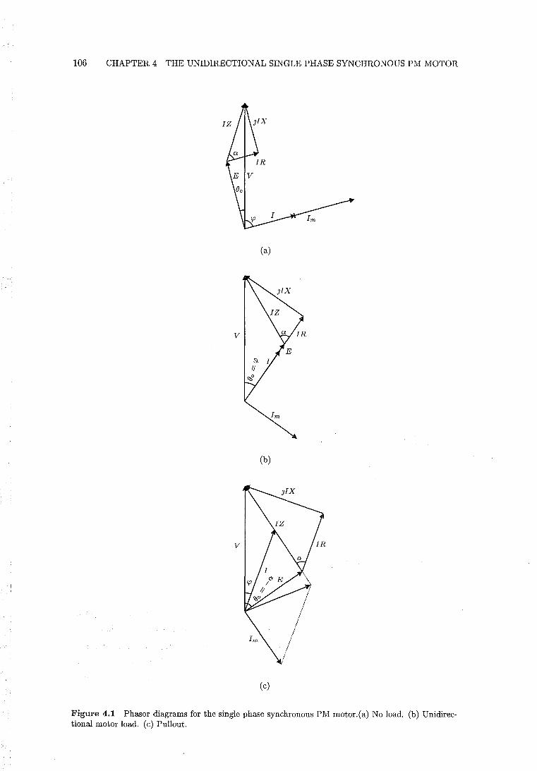
106 CHAPTER 4 THE UNIDIRECTIONAL SINGLE PHASE SYNCHRONOUS PM MOTOR
(a)
v
(b)
v
(c)
Figure 4.1 Phasor diagrams for the single phase synchronous PM motor.(a) No load. (b) Unidirectional motor load. (c) Pullout.
4.4 SIMULATION OF THE UNIDIRECTIONAL MOTOR 107
Eqn. 4.10 gives the same value for T as eqn. 4.45 for the unidirectional load. Therefore,
by equivalence
( 4.46)
and the unidirectional load angle, at which E and I are in phase, is
()o = arcsin (~ sin 0:) - 0: (4.47)
The electromagnetic power is obtained by multiplying eqn. 4.45 by iJ to get
A A2
Pout = 2~JfP - (esino:)2 - ;z coso: (4.48)
Expressing the unidirectional motor torque as a fraction of the pullout torque is useful
for the purpose of design. This pullout ratio is obtained by dividing eqn. 4.45 by eqn.
4.12:
(4.49)
4.4 SIMULATION OF THE UNIDIRECTIONAL MOTOR
In this section, the principle of the unidirectional motor is demonstrated by simulation.
The PM reluctance torque of a conventional motor is modified for the simulation. This
modification allows the conventional motor to be simulated as a unidirectional motor.
4.4.1 Derivation of the PM Reluctance Torque
The PM reluctance torque for a single pole pair motor is given in Chapter 1 by eqn.
1.8. In this section, an equation for the PM reluctance torque for a motor having an
arbitrary number of pole pairs is developed. The stored energy of single pole pair and
multiple pole pair motors is determined in section 4.8. It is shown that a reasonable
approximation of the stored energy is given by
W(i = 0) = Wro - Wr cos[2p(() -l'r)] (4.50)
where
Wro DC component of the stored field energy (when i = 0)
Wr = amplitude of the stored energy modulation (when i = 0)
l'r is measured in mechanical units. The stored energy is modulated at twice the rate
108 CHAPTER 4 THE UNIDIRECTIONAL SINGLE PHASE SYNCHRONOUS PM MOTOR
of the PM flux linkage. The PM reluctance torque is given by
dW(i=O) h
Tr = - dB = -2pWr sin[2p(B - 'Yr)] ( 4.51)
which is identical to eqn. 1.8 for p = 1. The amplitude of the reluctance torque is
given by
(4.52)
4.4.2 State Equations
The electrical and mechanical equations of motion given in Chapter 1 by 1.5 and 1.7
may be presented in state equation form for the purpose of motor simulation. These
equations are extended here to accommodate an arbitrary number of pole pairs. With
the EMF/torque function given by eqn. 4.2, and the PM reluctance torque given by
eqn. 4.51, the state equations become
~~ = ~ [iP~m sin(pB) - 2pWr sin[2p(B - 'Yr)] - Ii]
dB . - =B dt
(4.53)
(4.54)
(4.55)
where 0, i, and B are the state variables. These equations forma set of nonlinear
ordinary differential equations which must be solved numerically. For p = 1, these
equations are identical to those given by [Schemmann 1971, p. 52] for motor simulation.
[Schemmann 1973] compares the simulation results of these equations to experimental
results for a single pair pole motor. Schemmann shows that
. .. the equations represent a behaviour completely analogous to that of
the motor. Not only do the equations reproduce the details of the motion
observed in the motor but there are no extraneous effects, i.e. effects not
observed in the motor.
These equations are used to test the design of single pole pair motors [Diefenbach and
Schemmann 1989][Altenbernd 1991]. A unidirectional motor having a single pole pair
is simulated by setting appropriate values for T[, Tr, and 'Yr. The form of the equations
remains unaltered. Therefore, if the parameters of the unidirectional motor can be
accurately calculated, it is assumed that the simulation results will accurately predict
the motion of the unidirectional motor prior to its construction.
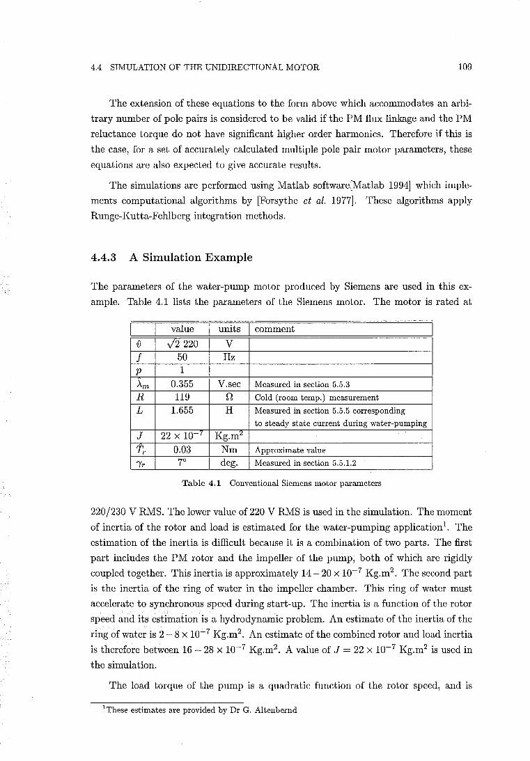
4.4 SIMULATION OF THE UNIDIRECTIONAL MOTOR 109
The extension of these equations to the form above which accommodates an arbi
trary number of pole pairs is considered to be valid if the PM flux linkage and the PM
reluctance torque do not have significant higher order harmonics. Therefore if this is
the case, for a set of accurately calculated multiple pole pair motor parameters, these
equations are also expected to give accurate results.
The simulations are performed using Matlab software[Matlab 1994] which imple
ments computational algorithms by [Forsythe et al. 1977]. These algorithms apply
Runge-Kutta-Fehlberg integration methods.
4.4.3 A Simulation Example
The parameters of the water-pump motor produced by Siemens are used in this ex
ample. Table 4.1 lists the parameters of the Siemens motor. The motor is rated at
value I units I comment {) y'2220 V
f 50 Hz p 1
Am 0.355 V.sec Measured in section 5.5.3
R 119 n Cold (room temp.) measurement
L 1.655 H Measured in section 5.5.5 corresponding
to steady state current during water-pumping
J 22 X 10 or Kg.m~
Tr 0.03 Nm Approximate value
'Yr 7° deg. Measured in section 5.5.1.2
Table 4.1 Conventional Siemens motor parameters
220/230 V RMS. The lower value of 220 V RMS is used in the simulation. The moment
of inertia of the rotor and load is estimated for the water-pumping application1. The
estimation of the inertia is difficult because it is a combination of two parts. The first
part includes the PM rotor and the impeller of the pump, both of which are rigidly
coupled together. This inertia is approximately 14 - 20 X 10-7 Kg.m2 . The second part
is the inertia of the ring of water in the impeller chamber. This ring of water must
accelerate to synchronous speed during start-up. The inertia is a function of the rotor
speed and its estimation is a hydrodynamic problem. An estimate of the inertia of the
ring of water is 2 - 8 X 10⁻⁷ Kg.m2. An estimate of the combined rotor and load inertia
is therefore between 16 - 28 x 10-7 Kg.m2 . A value of J = 22 X 10-7 Kg.m2 is used in
the simulation.
The load torque of the pump is a quadratic function of the rotor speed, and is
IThese estimates are provided by Dr G. Altenbernd
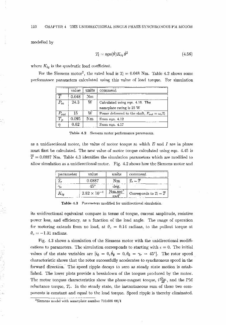
110 CHAPTER 4 THE UNIDIRECTIONAL SINGLE PHASE SYNCHRONOUS PM MOTOR
modelled by
. '2 Tz = sgn( (})Kzq () ( 4.56)
where KZq is the quadratic load coefficient.
For the Siemens motor2 , the rated load is Tz = 0.048 Nm. Table 4.2 shows some
performance parameters calculated using this value of load torque. For simulation
I value I units I comment
T 0.048 Nm
Pin 24.3 W Calculated using eqn. 4.16. The
nameplate rating is 25 W
Pout 15 W Power delivered to the shaft, Pout = WeTl
Tp 0.095 Nm From eqn. 4.12
'f} 0.62 From eqn. 4.17
Table 4.2 Siemens motor performance parameters.
as a unidirectional motor, the value of motor torque at which E and I are in phase
must first be calculated. The new value of motor torque calculated using eqn. 4.45 is
T = 0.0887 Nm. Table 4.3 identifies the simulation parameters which are modified to
allow simulation as a unidirectional motor. Fig. 4.2 shows how the Siemens motor and
I parameter I value units I comment
Tr 0.0887 Nm 'iT =T.
'Yr 45° deg.
Kzq 2.82 x 10⁻⁴ Nm.sec· Corresponds to 11 = T rad2
Table 4.3 Parameters modified for unidirectional simulation.
its unidirectional equivalent compare in terms of torque, current amplitude, resistive
power loss, and efficiency, as a function of the load angle. The range of operation
for motoring extends from no load, at (}o = 0.14 radians, to the pullout torque at
(}o = -1.31 radians.
Fig. 4.3 shows a simulation of the Siemens motor with the unidirectional modifi
cations to parameters. The simulation corresponds to starting with € = O. The initial
values of the state variables are [i0 = 0,00 = 0, (}0 = 'Yr = 45°]. The rotor speed.
characteristic shows that the rotor successfully accelerates to synchronous speed in the
forward direction. The speed ripple decays to zero as steady state motion is estab
lished. The lower plots provide a breakdown of the torques produced by the motor.
The motor torques characteristics show the phase-magnet torque, id~lf, and the PM
reluctance torque, Tr . In the steady state, the instantaneous sum of these two com
ponents is constant and equal to the load torque. Speed ripple is thereby eliminated.
2Siemens model with nameplate number 710.600 00/1
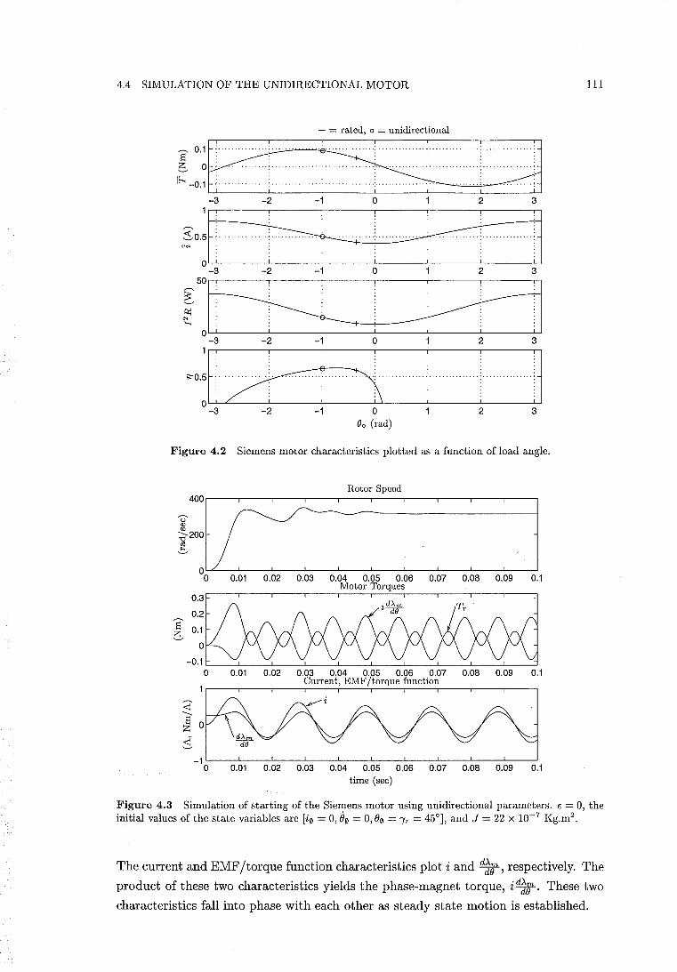
4.4 SIMULATION OF THE UNIDIRECTIONAL MOTOR 111
+ = rated, 0 = unidirectional
,~o:r: s==:E .. ! .±±J -3 -2 -1 0 2 3
50
~ ..• ~ .. ~: . : : . : : ~. . . . . . . ~O~I;~
-3 -2 -1 0 1 2 3
~o:l[·2f:5············[··············[··············i: -3 -2 -1 o 2 3
Bo (rad)
Figure 4.2 Siemens motor characteristics plotted as a function of load angle.
Rotor Speed 400
,-, u Q) tI.l :a-2OO cd ...::.,
0.Q1 0.02 0.03 0.04 0.05 0.06 0.07 0.08 0.09 0.1 Motor Torques
S 0.1 e -0.1
0 0.Q1 0.02 0.03 0.04 0.05 0.06 0.07 0.08 0.09 0.1 Current, EMF/torque function
~ ---S z :i
-1 0 0.Q1 0.02 0.03 0.04 0.05 0.06 0.07 0.08 0.09 0.1
time (sec)
Figure 4.3 Simulation of starting of the Siemens motor using unidirectional parameters. E = 0, the initial values of the state variables are [i0 = 0, e0 = 0, (}0 = 'YT = 45°], and J = 22 X 10-7 Kg.m2.
The current and EMF/torque function characteristics plot i and d1om , respectively. The
product of these two characteristics yields the phase-magnet torque, i d~rt. These two
characteristics fall into phase with each other as steady state motion is established.
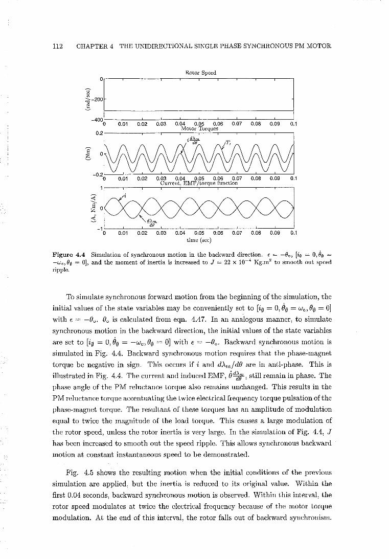
112 CHAPTER 4 THE UNIDIRECTIONAL SINGLE PHASE SYNCHRONOUS PM MOTOR
Rotor Speed 0
U Q)
~-200 ro ~
-400 0 0.01 0.02 0.03 0.04 0.05 0.06 0.07 0.08 0.09 0.1
0.2 Motor Torques
S e-
0.01 0.02 0.03 0.04 0.05 0.06 0.07 Current, EMF/torque function
0.08 0.09 0.1
_1L----L--~~~~--~----l----L----L----L--~--~ o 0.01 0.02 0.03 0.04 0.05 0.06 0.07 0.08 0.09 0.1
time (sec)
Figure 4.4 Simulation of synchronous motion in the backward direction. € = -Bo, [i0 = 0,80 = -We, B0 = 0], and the moment of inertia is increased to J = 22 X 10-4 Kg.m2 to smooth out speed ripple.
To simulate synchronous forward motion from the beginning of the simulation, the
initial values of the state variables may be conveniently set to [i0 = 0,00 = we, ()0 = OJ
with E = -()o. ()o is calculated from eqn. 4.47. In an analogous manner, to simulate
synchronous motion in the backward direction, the initial values of the state variables
are set to [i0 = 0,00 = -we, ()0 = OJ with E = -()o. Backward synchronous motion is
simulated in Fig. 4.4. Backward synchronous motion requires that the phase-magnet
torque be negative in sign. This occurs if i and dAm/ d() are in anti-phase. This is
illustrated in Fig. 4.4. The current and induced EMF, OddS', still remain in phase. The
phase angle of the PM reluctance torque also remains unchanged. This results in the
PM reluctance torque accentuating the twice electrical frequency torque pulsation of the
phase-magnet torque. The resultant of these torques has an amplitude of modulation
equal to twice the magnitude of the load torque. This causes a large modulation of
the rotor speed, unless the rotor inertia is very large. In the simulation of Fig. 4.4, J
has been increased to smooth out the speed ripple. This allows synchronous backward
motion at constant instantaneous speed to be demonstrated.
Fig. 4.5 shows the resulting motion when the initial conditions of the previous
simulation are applied, but the inertia is reduced to its original value. Within the
first 0.04 seconds, backward synchronous motion is observed. Within this interval, the
rotor speed modulates at twice the electrical frequency because of the motor torque
modulation. At the end of this interval, the rotor falls out of backward synchronism.
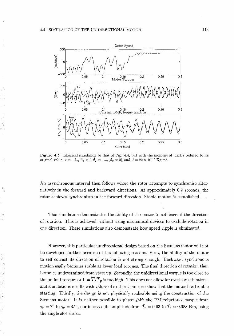
4.4 SIMULATION OF THE UNIDIRECTIONAL MOTOR 113
Rotor Speed 500
U' Q)
'" --... "Cj
cO ~
0.05 0.1 0.15 0.2 0.25 0.3 Motor Torques
S e
0 0.05 0.1 0.15 0.2 0.25 0.3 Current, EMF/torque function
~ --... S z ~
0.05 0.1 0.15 0.2 0.25 0.3 time (sec)
Figure 4.5 Identical simulation to that of Fig. 4.4, but with the moment of inertia reduced to its original value. E = -Bo, [i0 = 0, B0 = -We, B0 = 0], and J = 22 X 10-7 Kg.m2.
An asynchronous interval then follows where the rotor attempts to synchronise alter
natively in the forward and backward directions. At· approximately. 0.2 seconds, the
rotor achieves synchronism in the forward direction. Stable motion is established.
This simulation demonstrates the ability of the motor to self correct the direction
of rotation. This is achieved without using mechanical devices to exclude rotation in
one direction. These simulations also demonstrate how speed ripple is eliminated.
However, this particular unidirectional design based on the Siemens motor will not
be developed further because of the following reasons. First, the ability of the motor
to self correct its direction of rotation is not strong enough. Backward synchronous
motion easily becomes stable at lower load torques. The final direction of rotation then
becomes undetermined from start up. Secondly, the unidirectional torque is too close to
the pullout torque, or r = T /Tp is too high. This does not allow for overload situations,
and simulations results with values of E other than zero show that the motor has trouble
starting. Thirdly, the design is not physically realisable using the construction of the
Siemens motor. It is neither possible to phase shift the PM reluctance torque from
'Yr = 7° to 'Yr = 45°, nor increase its amplitude from Tr = 0.03 to Tr = 0.088 Nm, using
the single slot stator.
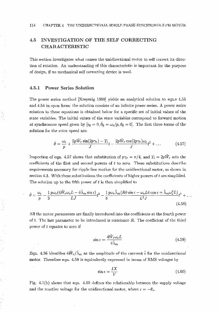
114 CHAPTER 4 THE UNIDIRECTIONAL SINGLE PHASE SYNCHRONOUS PM MOTOR
4.5 INVESTIGATION OF THE SELF CORRECTING CHARACTERISTIC
This section investigates what causes the unidirectional motor to self correct its direc
tion of rotation. An understanding of this characteristic is important for the purpose
of design, if no mechanical self correcting device is used.
4.5.1 Power Series Solution
The power series method [Kreyszig 1988] yields an analytical solution to eqn.s 4.53
and 4.54 in open form: the solution consists of an infinite power series. A power series
solution to these equations is obtained below for a specific set of initial values of the
state variables. The initial values of the state variables correspond to forward motion
at synchronous speed given by [i0 = 0,80 = we/p, 00 = 0]. The first three terms of the
solution for the rotor speed are:
O· _ We 2pWr sin(2Pl'r) - T" _ 2pWr cos (2PI'r )We 2
- P + J t J t + ... (4.57)
Inspection of eqn. 4.57 shows that substitution of PI'r = 1f/4, and Tz = 2pWr sets the
coefficients of the first and second powers of t to zero. These substitutions describe
requirements necessary for ripple free motion for the unidirectional motor, as shown in
section 4.3. With these substitutions the coefficients of higher powers of t are simplified.
The solution up to the fifth power of t is then simplified to
8 _ We _ !pwe(4WrweL - V~m sinE) 3 _ !PWe~m(Rv sinE - WeLv cos E + ~mw~L) 4 - P 3 LJ t 8 L2J t + ...
(4.58)
All the motor parameters are finally introduced into the coefficients at the fourth power
of t. The last parameter to be introduced is resistance R. The coefficient of the third
power of t equates to zero if
( 4.59)
Eqn. 4.36 identifies 4 Wr / ~m as the amplitude of the currrent i for the unidirectional
motor. Therefore eqn. 4.59 is equivalently expressed in terms of RMS voltages by
. IX sInE = V (4.60)
Fig. 4.1(b) shows that eqn. 4.60 defines the relationship between the supply voltage
and the reactive voltage for the unidirectional motor, where E = -00 ,
4.5 INVESTIGATION OF THE SELF CORRECTING CHARACTERISTIC 115
The coefficient of the fourth power of t equates to zero if
(4.61)
Substitution of eqn. 4.59 into eqn. 4.61 allows eqn. 4.61 to be solved as
VCOSE = IR+E (4.62)
Fig. 4.1(b) shows that eqn. 4.62 describes the relationship between the supply voltage,
the resistive voltage, and the induced EMF for the unidirectional motor, where E =
-00 , All of the requirements and relationships between motor parameters for the
unidirectional motor have been defined above. This has been achieved by setting to
zero and solving the coefficients of the first four powers of t in the power series. The
analysis of section 4.3 shows that the rotor speed is constant if these requirements and
initial conditions are in place. Therefore all power series terms corresponding to higher
powers of t must equate to zero. In this case the power series converges to e = we/p
for all values of t.
This specific power series solution yields neither insight into the self correcting
characteristic nor the motor parameters which may have a predominant role. Power
series solutions corresponding to other combinations of initial states do not yield any
clearer insight into the self correcting characteristic.
4.5.2 Approximate Condition for Failure of Backward Synchronous Motion
Fig. 4.5 illustrates an example of a unidirectional motor simulation where loss of back
ward synchronism occurs over multiple electrical cycles. However, loss of backward
synchronism within an electrical cycle, corresponding to a stronger self correcting char
acteristic, is desirable. In this section, a condition corresponding to loss of backward
synchronism within an electrical cycle is determined. An analytical expression which
identifies key motor parameters is obtained.
Fig. 4.6 plots the PM reluctance torque, Tr , and the EMF/torque function,
dAm/dO = P~m sinpO, for the unidirectional motor. These characteristics are plotted
over half an electrical cycle centred at 0 = O. The PM stored energy W(i = 0) is also
shown. Within the quadrant 0 = - ,; ... ,;, the magnitude of dAm/ dO is significantly
smaller than it is in the quadrant spanning 0 = - ~ ... - ,;, ,; ... ~. Within the
former quadrant, dAm/dO diminishes to zero, and Tr peaks, towards 0 = O. Therefore,
within this quadrant, and particularly near 0 = 0, the magnitude of the phase-magnet
torque i d~[f' is reduced. This reduction is significant regardless of the magnitude of
the current. In contrast, near 0 = 0, Tr is not reduced and has a large amplitude for
a unidirectionally designed motor. Therefore the following simplifying approximations
116 CHAPTER 4 THE UNIDIRECTIONAL SINGLE PHASE SYNCHRONOUS PM MOTOR
W(i = 0)
unstable detent stable detent
__________________ L _____ ~ ________ i _______________ -l------------------j lVr j :
1:::, '1' 1;- ~":, i 'Yr 0-'----'---------'-------'--------'
T - _dW(i=O)
, - I" o -+-------1t-----" *: '----~--_____1
, III , :
, I
7r
2p
Figure 4.6 PM reluctance torque TTl EMF/torque function dAm/dB, and PM stored energy W(i = 0), about B = 0 for the unidirectional motor.
may be made to the mechanical equation of motion about () = O. The phase-magnet
torque i d~lf may be omitted from eqn. 4.53. The angular acceleration is then deter
mined without requiring calculation of i. By also neglecting the load torque Tz, eqn.
4.53 is approximated about () = 0 for a unidirectional motor by
JdiJ ~ 2pWr cos (2p()) . dt
(4.63)
With reference to Fig. 4.6, eqn. 4.63 shows that over the interval () = -,; ... ,;, the PM reluctance torque yields an angular acceleration in the forward direction of
rotation. It may then be supposed that if the rotor is running at synchronous speed
in the backward direction at () = 7r / 4p, it is possible for the rotor to de-accelerate and
come to rest on or before () = -7r / 4p. The rotor may then be accelerated in the forward
direction from () = -,; to ,;. This describes a self correcting process.
In the interval () = ,; ... ~, -~ ... - ,;, the PM reluctance torque will be un
successful at reversing synchronous motion in the forward direction, in an analogous
manner to that described above. This is because, in this quadrant, torques i d~lf' and
Tr superimpose to yield a constant net torque and zero acceleration.
Synchronous motion in the backward direction is still be possible. In this case
the torques i d~lf and Tr align in the manner shown by Fig. 4.4. Speed ripple is
present. Through each middle quadrant corresponding to () = -,; ... - ~, ~ ... ,;, both torques add to provide sufficient acceleration to allow the rotor to carry through
the de-accelerating quadrant, () = ,; ... - ,;. However, the backward motion becomes
less stable as speed ripple increases.
4.5 INVESTIGATION OF THE SELF CORRECTING CHARACTERISTIC 117
Eqn. 4.63 describes a conservative system where energy is transferred between
rotational stored energy and PM stored energy. The balance of energy corresponding
to the de-acceleration from backward synchronous speed to zero speed may be obtained
from eqn. 4.63 by
which evaluates to
~ /,,- z, 2pWr cos(2pO) dO 4p
1 '2 A
--JO ~ -2Wr 2
(4.64)
(4.65)
For backward synchronous speed to be reduced to zero over the interval 0 = ; ... - ;,
the amount of energy able to be stored magnetically by the PM must be at least as
great as the rotational energy required to be transferred to reduce the speed to zero.
In this case eqn. 4.65 may be expressed in the form of the inequality:
A 2 4WrP 1
J 2 > We
(4.66)
where the substitution e = we/p relates the mechanical speed to the electrical angular
speed. Eqn. 4.66 defines an approximate condition required for failure of backward
synchronism. This ideally occurs over a quarter of an electrical cycle, but is possible
over a number of cycles. The ratio 4Wrp2 / Jw~ will be referred to. as the backward
instability ratio. Simulation results have shown that eqn. 4.66 provides, in general,
a useful indication of whether a unidirectional design is likely to have a sufficient self
correcting characteristic. For the example of the Siemens motor using unidirectional
parameters, the self correcting characteristic is not strong, and the backward instability
ratio is only 0.82. Simulation results show that if the backward instability ratio is high
enough, backward synchronous motion will in general be unstable, within a useful range
of motor parameter variation.
The influence of the load torque has been neglected in the formulation of eqn. 4.66.
The effect of the load torque is to extract stored energy as the rotor de-accelerates and
accelerates. This is explained with reference to Fig. 4.6. During de-acceleration from
o = 1f /4p, rotational energy is transferred into PM stored energy, and is also transferred
to the load. This aids de-acceleration such that the rotor may come to rest before reach
ing 0 = -1f /4p. The PM reluctance torque then accelerates the rotor in the forward
direction. However, the amount of PM stored energy available to accelerate the rotor
to synchronous speed is reduced because the rotor starts accelerating forward closer to
the stable detente at 0 = 1f /4p. During acceleration, the available energy is transferred
into rotational stored energy, and is also transferred to the load. This further reduces
the amount of energy available to be converted into rotational energy. The available
118 CHAPTER 4 THE UNIDIRECTIONAL SINGLE PHASE SYNCHRONOUS PM MOTOR
energy may then be insufficient to bring the rotor up to forward synchronous speed by
e = 1f/4p.
The influence of the load torque requires that the backward instability ratio be
higher than unity to compensate for stored energy lost to the load.
4.6 FORMULATION OF TWO UNIDIRECTIONAL MOTOR DESIGNS
In this section, two unidirectional motor designs are formulated. The aim of the designs
is for each motor to be able to self correct its direction of rotation. This is to be achieved
without the requirement of a mechanical self correcting device.
Eqn. 4.66 may be used as a design tool for the development of these unidirectional
motor designs. Achieving the design aim requires the backward instability ratio to be
maximised. The motor parameters We, J, Wr , andp feature in this ratio. The electrical
angular speed We cannot be varied if the motor is directly connected to the electrical
AC supply. Therefore We may be considered to be a constant. The moment of inertia
of the PM rotor is given by
(4.67)
where
e rotor mass density
Lr = length of rotor
l)r rotor diameter
The inertia of the rotor Jr is generally larger than that of the load, and contributes
most significantly to the total inertia J. Eqn. 4.67 shows that decreasing the rotor di
ameter strongly decreases the rotor inertia. Therefore, the total inertia is also strongly
decreased. A physical limit to the rotor diameter exists at which further increases in
diameter and inertia inhibit adequate acceleration to synchronous speed [Bertram and
Schemmann 1976]. This illustrates why the size and power rating of the conventional
motor is small. For the unidirectional motor, decreasing the rotor diameter very signif
icantly increases the backward instability ratio. However, doing this reduces the power
rating of the motor. In each of the two designs, an attempt is made to maximise power
rating, thereby maximising rotor diameter and inertia. Reduction of the rotor diameter
will only be used as a last design option to raise the backward instability ratio to a
sufficiently high value. Each of the motor designs is based on maximising one of the two
remaining parameters in the backward instability ratio. These designs are introduced
in sections 4.6.1 and 4.6.2.
4.6 FORMULATION OF TWO UNIDIRECTIONAL MOTOR DESIGNS 119
4.6.1 A Single Pole Pair Design
This design maximises the amplitude of the PM stored energy modulation Wr . The
results obtained from the analysis of section 3.6 show that Wr increases as the amplitude
of airgap modulation is increased. Dimension Lt is maximised for both designs. The
example of section 3.6.1 shows clearly that Wand Wr are proportional to the square
of the PM remanent flux density Br. For the single pole pair design, Wr is increased
by increasing B r . This is achieved by using a higher grade of magnet. The bonded
Nd-Fe-B grade of magnet specified in section 3.3.2.1 is used. The increased magnitude
of Wr , in relation to J, permits a single pole pair design to be implemented. This
design is developed in section 4.9.
4.6.2 A Multiple Pole Pair Design
This design implements multiple pole pairs to allow ferrite grade magnets to be used.
With ferrite magnets, the magnitude of Wr in relation to J is lower. This is compen
sated for by increasing the number of pole pairs. The ferrite material has the economic
attraction of being a cheap PM material. This enables conventional 2-pole motors of
this type to be economically feasible in the low performance and low power applications
in which they are used. This design uses three pole pairs and is developed in section
4.10. The rotor speed of this motor connected to a 50 Hz supply is 1000 RPM.
4.6.3 Physical Implementation
This section explains how the single and multiple pole pair designs may be physically
realised. Each unidirectional design requires:
1. A sinusoidal EMF /torque function, dAm/dO.
2. A sinusoidal PM reluctance torque of amplitude equal to the rated torque, dis
placed to a phase angle of P '"'Ir = 45° electrical.
3. The above characteristics implemented in a manufacturable design.
A conventional 2-pole synchronous PM motor has a single set of airgaps. The
airgap around the stator iron is modulated by the asymmetric steps. Experimental
measurement of the induced EMF in section 5.5.3 shows that the fundamental compo
nent is dominant. The third harmonic has a range of 3-5% and higher order harmonics
are negligible. This implies that the asymmetric airgap modulation has little distorting
effect on the EMF/torque function. This demonstrates that the 2-pole parallel magne
tised rotor design of the conventional motor enables a sinusoidal EMF/torque function
to be obtained, even with modulation of the airgap to allow a PM reluctance torque
to be obtained. The parallel magnetised rotor of the conventional motor will be used
120 CHAPTER 4 THE UNIDIRECTIONAL SINGLE PHASE SYNCHRONOUS PM MOTOR
in the unidirectional designs. The mechanisms influencing EMF /torque function shape
are examined in section 4.7.
The PM reluctance torque of the conventional 2-pole motor is approximated by
a sinusoid, as described in section 1.2.1. A remaining requirement is to establish the
P"Ir = 450 (electrical) displacement angle. In the conventional single slot design, the slot
is predominantly responsible for the magnitude and phase of the PM reluctance torque.
If the asymmetric stator steps are removed, the PM reluctance torque remains present
with a displacement angle of P"Ir = O. The asymmetric steps, or alternative saturating
notches, act to phase shift this torque by a small angle which is sufficient for starting.
To establish a large displacement angle, the slots must be eliminated altogether. This
is achieved in the slotless 2-pole design of Fig. 1.2 (b). A displacement angle of "II' = 900
is obtained. However, unidirectional synchronous motion requires that "II' = 450• The
stator construction of the motor of Fig. 1.2(b) will be adopted. But a suitable air gap
modulation will be employed to achieve the desired displacement angle. In the paper
"Effects of Airgap and Magnet Shapes on Permanent Magnet Reluctance Torque" in
Appendix A, the shape of the reluctance torque appears to correlate to the shape
of the airgap modulation for the examples analysed. For the unidirectional motor a
sinusoidal reluctance torque containing minimal harmonics is required. A sinusoidal
airgap modulation is employed. The displacement angle P"Ir = 450 is achieved by
rotating the axis of the airgap modulation an appropriate angle from the stator d-axis.
The PM reluctance torques of parallel magnetised rotors with sinusoidally modulated
airgaps are examined analytically in section 4.8.
A stator design based on that of the motor of Fig. 1.2(b) also satisfies the re
quirement of a manufacturable design. A motor of this small size connected directly
to the mains supply typically requires thousands of turns. This stator design permits
the turns to be prewound onto formers, before being slotted onto the pole shanks. The
stator ring or yoke is then fitted over the pole shanks.
The multiple pole pair design solution is to duplicate the single pole pair design.
An example of this design is shown in Fig. 4.50. The rotor consists of alternately
parallel magnetised PM sectors. In section 4.7, it is shown that this multiple pole pair
design is more prone than the single pole pair design to harmonics in the EMF/torque
function. As already mentioned, a limit on the rotor inertia places a limit on the
rotor diameter. This limit makes the rotor diameter too small for the multiple slots
per pole designs of larger electrical machines to be applied. Concentrated coils are
necessary. This precludes the use of standard space harmonic suppression techniques
such as distributed, chorded, and skewed coils [McPherson 1981, pp. 79-87] to improve
the EMF/torque function.
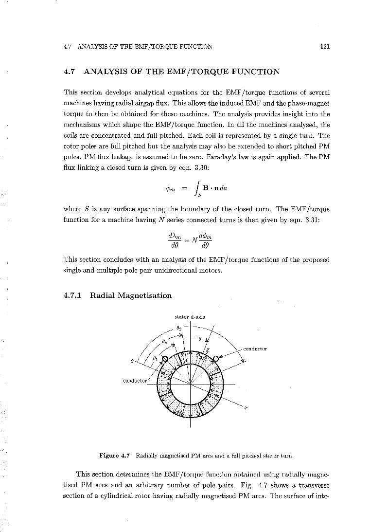
4.7 ANALYSIS OF THE EMF/TORQUE FUNCTION 121
4.7 ANALYSIS OF THE EMF/TORQUE FUNCTION
This section develops analytical equations for the EMF/torque functions of several
machines having radial airgap flux. This allows the induced EMF and the phase-magnet
torque to then be obtained for these machines. The analysis provides insight into the
mechanisms which shape the EMF/torque function. In all the machines analysed, the
coils are concentrated and full pitched. Each coil is represented by a single turn. The
rotor poles are full pitched but the analysis may also be extended to short pitched PM
poles. PM flux leakage is assumed to be zero. Faraday's law is again applied. The PM
flux linking a closed turn is given by eqn. 3.30:
¢m = Is B· nda
where S is any surface spanning the boundary of the closed turn. The EMF/torque
function for a machine having N series connected turns is then given by eqn. 3.31:
dAm _ Nd¢m --- --dB dB
This section concludes with an analysis of the EMF/torque functions of the proposed
single and multiple pole pair unidirectional motors.
4.7.1 Radial Magnetisation
stator d-axis
Figure 4.7 Radially magnetised PM arcs and a full pitched stator turn.
This section determines the EMF/torque function obtained using radially magne
tised PM arcs and an arbitrary number of pole pairs. Fig. 4.7 shows a transverse
section of a cylindrical rotor having radially magnetised PM arcs. The surface of inte-
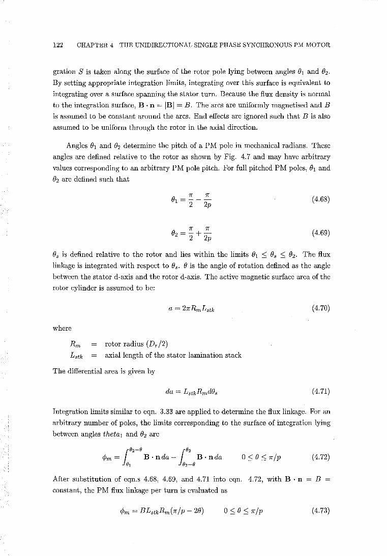
122 CHAPTER 4 THE UNIDIRECTIONAL SINGLE PHASE SYNCHRONOUS PM MOTOR
gration S is taken along the surface of the rotor pole lying between angles 01 and O2 .
By setting appropriate integration limits, integrating over this surface is equivalent to
integrating over a surface spanning the stator turn. Because the flux density is normal
to the integration surface, B . n = IBI = B. The arcs are uniformly magnetised and B
is assumed to be constant around the arcs. End effects are ignored such that B is also
assumed to be uniform through the rotor in the axial direction.
Angles 01 and (h determine the pitch of a PM pole in mechanical radians. These
angles are defined relative to the rotor as shown by Fig. 4.7 and may have arbitrary
values corresponding to an arbitrary PM pole pitch. For full pitched PM poles, 01 and
O2 are defined such that
Jr 1f 01 = - --
2 2p
1f 1f O2 = -+-
2 2p
(4.68)
(4.69)
Os is defined relative to the rotor and lies within the limits 01 ::; Os ::; O2 . The flux
linkage is integrated with respect to Os. 0 is the angle of rotation defined as the angle
between the stator d-axis and the rotor d-axis. The active magnetic surface area of the
rotor cylinder is assumed to be:
(4.70)
where
Rm = rotor radius (Dr/2) Lstk axial length of the stator lamination stack
The differential area is given by
(4.71)
Integration limits similar to eqn. 3.33 are applied to determine the flux linkage. For an
arbitrary number of poles, the limits corresponding to the surface of integration lying
between angles theta1 and O2 are
(4.72)
After substitution of eqn.s 4.68, 4.69, and 4.71 into eqn. 4.72, with B . n = B =
constant, the PM flux linkage per turn is evaluated as
(4.73)
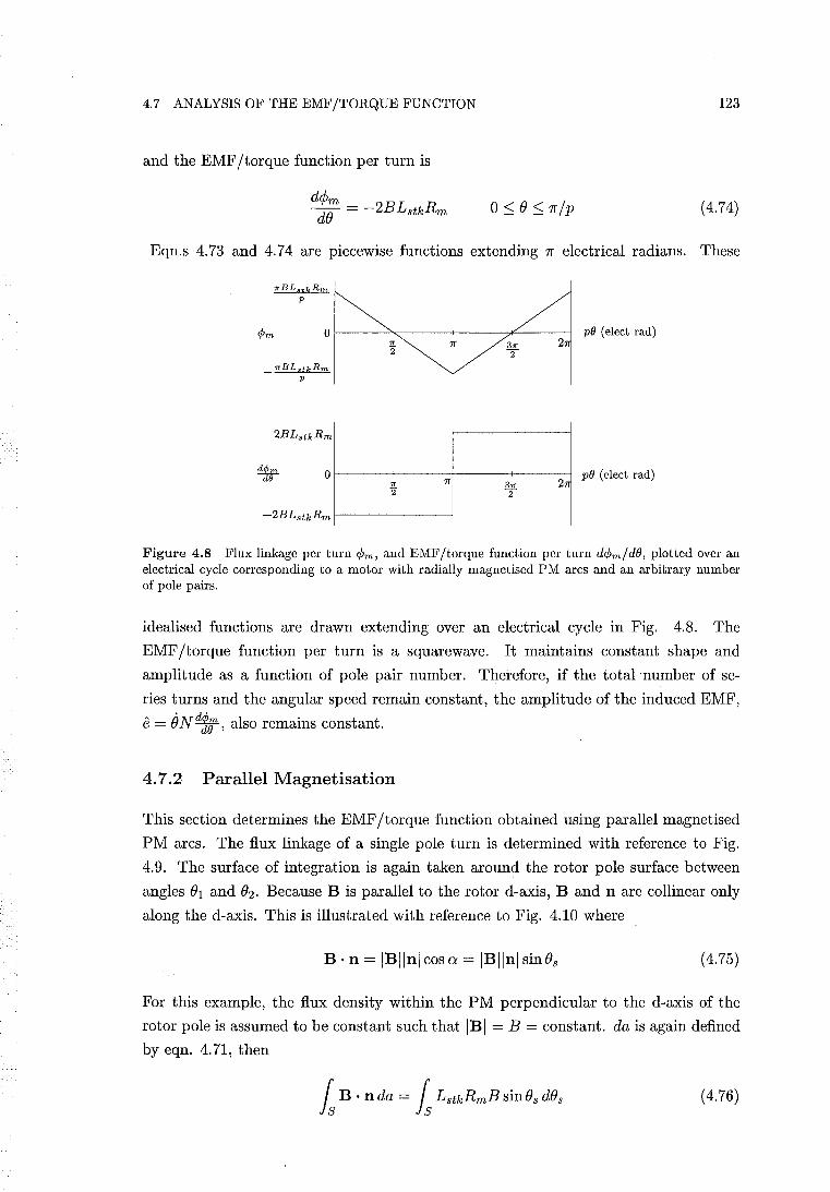
4.7 ANALYSIS OF THE EMF/TORQUE FUNCTION 123
and the EMF/torque function per turn is
d¢m de = - 2BLstkRm (4.74)
Eqn.s 4.73 and 4.74 are piecewise functions extending 1f electrical radians. These
~ de
O~----~-----+----~~----~ 2
Or-----~-----+------+-----~ ".
'2 27T
pO (elect rad)
pO (elect rad)
Figure 4.8 Flux linkage per turn tPm, and EMF/torque function per turn dcpm/dB, plotted over an electrical cycle corresponding to a motor with radially magnetised PM arcs and an arbitrary number of pole pairs.
idealised functions are drawn extending over an electrical cycle in Fig. 4.8. The
EMF /torque function per turn is a squarewave. It maintains constant shape and
amplitude as a function of pole pair number. Therefore, if the total number of se
ries turns and the angular speed remain constant, the amplitude of the induced EMF,
e = iJNdl;, also remains constant.
4.7.2 Parallel Magnetisation
This section determines the EMF/torque function obtained using parallel magnetised
PM arcs. The flux linkage of a single pole turn is determined with reference to Fig.
4.9. The surface of integration is again taken around the rotor pole surface between
angles (h and fh Because B is parallel to the rotor d-axis, Band n are collinear only
along the d-axis. This is illustrated with reference to Fig. 4.10 where
B· n = IBllnl cos a = IBllnl sin Os (4.75)
For this example, the flux density within the PM perpendicular to the d-axis of the
rotor pole is assumed to be constant such that IBI = B = constant. da is again defined
by eqn. 4.71, then
(4.76)
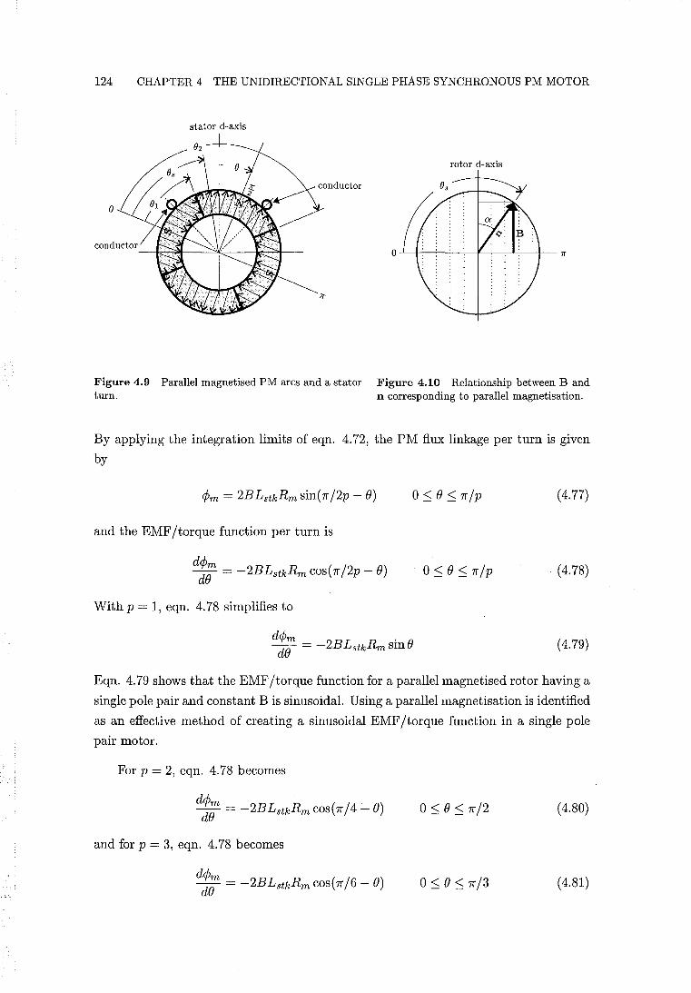
124 CHAPTER 4 THE UNIDIRECTIONAL SINGLE PHASE SYNCHRONOUS PM MOTOR
stator d-axis
rotor d-axis
Figure 4.9 Parallel magnetised PM arcs and a stator Figure 4.10 Relationship between Band turn. n corresponding to parallel magnetisation.
By applying the integration limits of eqn. 4.72, the PM flux linkage per turn is given
by
(4.77)
and the EMF jtorque function per turn is
(4.78)
With p = 1, eqn. 4.78 simplifies to
(4.79)
Eqn. 4.79 shows that the EMF jtorque function for a parallel magnetised rotor having a
single pole pair and constant B is sinusoidal. Using a parallel magnetisation is identified
as an effective method of creating a sinusoidal EMF jtorque function in a single pole
pair motor.
For p = 2, eqn. 4.78 becomes
(4.80)
and for p = 3, eqn. 4.78 becomes
(4.81)
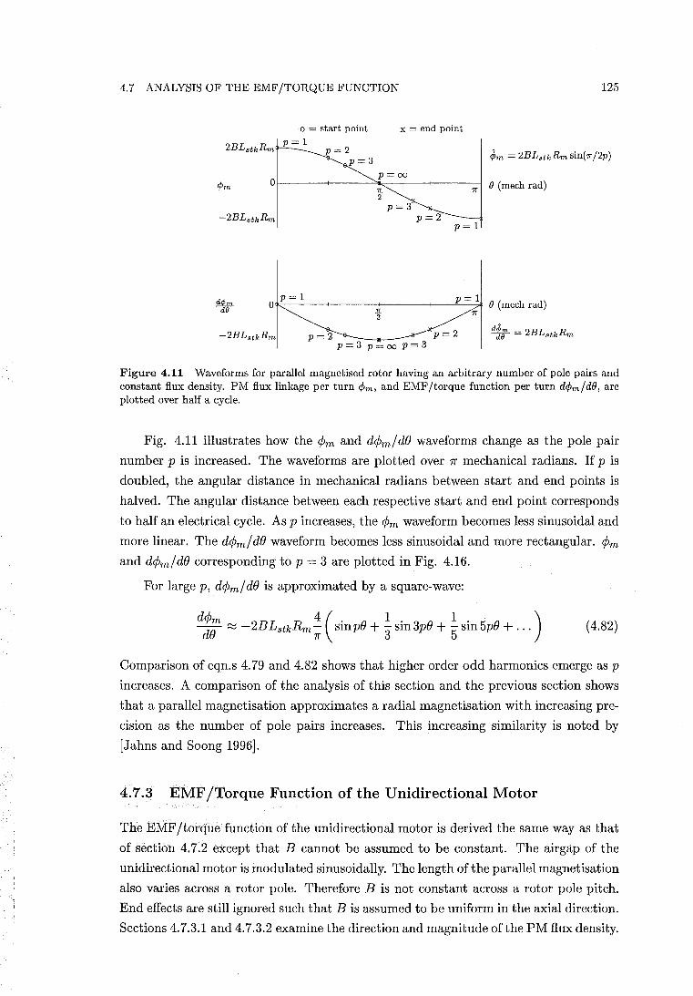
4.7 ANALYSIS OF THE EMF/TORQUE FUNCTION
x = end point a = start point p=l
2BLstkRm p = 2
dpm dO
p=3 p= 00
Of-----+-------=,.".------+----71'----1 B (mech rad) 2"
p=3 p=2
p=l
p=l p=l O~----+----4".f-----+-----"----:;7r'* B (mech rad)
2"
p=2 p=3 p=oo p=3
125
Figure 4.11 Waveforms for parallel magnetised rotor having an arbitrary number of pole pairs and constant flux density. PM flux linkage per turn <Pm, and EMF/torque function per turn d<pm / dB, are plotted over half a cycle.
Fig. 4.11 illustrates how the <Pm and d<pm/dB waveforms change as the pole pair
number p is increased. The waveforms are plotted over 1f' mechanical radians. If p is
doubled, the angular distance in mechanical radians between start and end points is
halved. The angular distance between each respective start and end point corresponds
to half an electrical cycle. As p increases, the <Pm waveform becomes less sinusoidal and
more linear. The d<pm / dB waveform becomes less sinusoidal and more rectangular. <Pm
and d<pm/dB corresponding to p = 3 are plotted in Fig. 4.16.
For large p, d<pm/ dB is approximated by a square-wave:
d:;; ~ -2BLstkRmt (sinPB + 1 sin3pB + ~ sin5pB + ... ) (4.82)
Comparison of eqn.s 4.79 and 4.82 shows that higher order odd harmonics emerge as p
increases. A comparison of the analysis of this section and the previous section shows
that a parallel magnetisation approximates a radial magnet is at ion with increasing pre
cision as the number of pole pairs increases. This increasing similarity is noted by
[Jahns and Soong 1996].
4.7.3 EMF/Torque Function of the Unidirectional Motor
The EMF/torque function of the unidirectional motor is derived the same way as that
of section 4.7.2 except that B cannot be assumed to be constant. The airgap of the
unidirectional motor is modulated sinusoidally. The length of the parallel magnetisation
also varies across a rotor pole. Therefore B is not constant across a rotor pole pitch.
End effects are still ignored such that B is assumed to be uniform in the axial direction.
Sections 4.7.3.1 and 4.7.3.2 examine the direction and magnitude of the PM flux density.
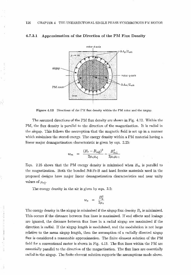
126 CHAPTER 4 THE UNIDIRECTIONAL SINGLE PHASE SYNCHRONOUS PM MOTOR
4.7.3.1 Approximation of the Direction of the PM Flux Density
rotor d-axis
airgap
+-r-,--t- rotor q-axis
PM
Figure 4.12 Directions of the PM flux density within the PM rotor and the airgap.
The assumed directions of the PM flux density are shown in Fig. 4.12. Within the
PM, the flux density is parallel to the direction of the magnetisation. It is radial in
the airgap. This follows the assumption that the magnetic field is set up in a manner
which minimises the stored energy. The energy density within a PM material having a
linear major demagnetisation characteristic is given by eqn. 2.25:
Wm = (Br - Bmll)2 + B!1-.
21-lol-lrll 21-lol-lr 1-
Eqn. 2.25 shows that the PM energy density is minimised when Bm is parallel to
the magnetisation. Both the bonded Nd-Fe-B and hard ferrite materials used in the
proposed designs have major linear demagnetisation characteristics and near unity
values of I-lrll'
The energy density in the air is given by eqn. 3.2:
Wa =
The energy density in the airgap is minimised if the airgap flux density Ba is minimised.
This occurs if the distance between flux lines is maximised. If end effects and leakage
are ignored, the distance between flux lines in a radial airgap are maximised if the
direction is radial. If the airgap length is modulated, and the modulation is not large
relative to the mean airgap length, then the assumption of a radially directed airgap
flux is considered a reasonable approximation. The finite element solution of the PM
field for a conventional motor is shown in Fig. 4.13. The flux lines within the PM are
essentially parallel to the direction of the magnetisation. The flux lines are essentially
radial in the airgap. The finite element solution supports the assumptions made above.
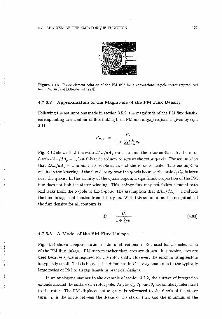
4.7 ANALYSIS OF THE EMF/TORQUE FUNCTION 127
Figure 4.13 Finite element solution of the PM field for a conventional 2-pole motor (reproduced form Fig. 6(b) of [Altenbernd 1991]).
4.7.3.2 Approximation of the Magnitude of the PM Flux Density
Following the assumptions made in section 3.5.2, the magnitude of the PM flux density
corresponding to a contour of flux linking both PM and airgap regions is given by eqn.
3.11:
Fig. 4.12 shows that the ratio dAm/dAg varies around the rotor surface. At the rotor
d-axis dAm/ dAg = 1, but this ratio reduces to zero at the rotor q-axis. The assumption
that dAm/dAg = 1 around the whole surface of the rotor is made. This assumption
results in the lowering ofthe flux density near the q-axis because the ratio 19/1m is large
near the q-axis. In the vicinity of the q-axis region, a significant proportion of the PM
flux does not link the stator winding. This leakage flux may not follow a radial path
and leaks from the N-pole to the S-pole. The assumption that dAm/dAg = 1 reduces
the flux linkage contribution from this region. With this assumption, the magnitude of
the flux density for all contours is
(4.83)
4.7.3.3 A Model of the PM Flux Linkage
Fig. 4.14 shows a representation of the unidirectional motor used for the calculation
of the PM flux linkage. PM sectors rather than arcs are drawn. In practice, arcs are
used because space is required for the rotor shaft. However, the error in using sectors
is typically small. This is because the difference in B is very small due to the typically
large ratios of PM to airgap length in practical designs.
In an analogous manner to the example of section 4.7.2, the surface of integration
extends around the surface of a rotor pole. Angles 01, O2 , and Os are similarly referenced
to the rotor. The PM displacement angle "Yr is referenced to the d-axis of the stator
turn. "Yr is the angle between the d-axis of the stator turn and the minimum of the
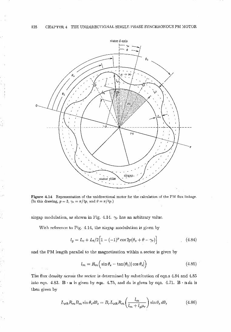
128 CHAPTER 4 THE UNIDIRECTIONAL SINGLE PHASE SYNCHRONOUS PM MOTOR
stator d-axis
o
Figure 4.14 Representation of the unidirectional motor for the calculation of the PM flux linkage. (In this drawing, p = 3, IT = 7r /4p, and e = 7r / 4p.)
airgap modulation, as shown in Fig. 4.14. 'Yr has an arbitrary value.
With reference to Fig. 4.14, the airgap modulation is given by
(4.84)
and the PM length parallel to the magnetisation within a sector is given by
( 4.85)
The flux density across the sector is determined by substitution of eqn.s 4.84 and 4.85
into eqn. 4.83. B· n is given by eqn. 4.75, and da is given by eqn. 4.71. B· n da is
then given by
( 4.86)
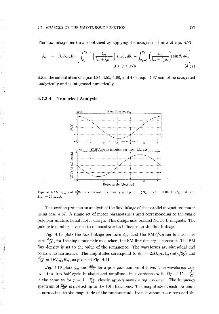
4.7 ANALYSIS OF THE EMF/TORQUE FUNCTION 129
The flux linkage per turn is obtained by applying the integration limits of eqn. 4.72:
BrLstkRm [ r02
-
O (z z~ ) sines des - r02 (z z~ ) sines des] J01 m + g/-lr J02 -0 m + g/-lr
05:.e5:.7r/p (4.87)
After the substitution of eqn.s 4.84, 4.85, 4.68, and 4.69, eqn. 4.87 cannot be integrated
analytically and is integrated numerically.
4.7.3.4 Numerical Analysis
-1
_2~ __ ~ ____ ~ ____ -L ____ -L ____ ~ ____ ~
o
~ S 1
'"0 ~ 0 <l
---~ -1
<l
3 5
~-~~--~----~2-----L3-----4~·-----5~--~6~
Rotor angle (elect rad)
Figure 4.15 rpm and ~ for constant flux density and p = 1. (Bm = Br = 0.66 T, Rm = 6 mm, Lstk = 20 mm).
This section presents an analysis of the flux linkage of the parallel magnetised motor
using eqn. 4.87. A single set of motor parameters is used corresponding to the single
pole pair unidirectional motor design. This design uses bonded Nd-Fe-B magnets. The
pole pair number is varied to demonstrate its influence on the flux linkage.
Fig. 4.15 plots the flux linkage per turn ¢m, and the EMF/torque function per
turn d1;, for the single pole pair case where the PM flux density is constant. The PM
flux density is set to the value of the remanence. The waveforms are sinusoidal and
contain no harmonics. The amplitudes correspond to ¢m = 2BLstkRm sin{7r/2p) and
d1; = 2BLstkRm, as given in Fig. 4.11.
Fig. 4.16 plots ¢m and d1; for a pole pair number of three. The waveforms vary
over the first half cycle in shape and amplitude in accordance with Fig. 4.11. d1; is the same as for p = 1. d1; closely approximates a square-wave. The frequency
spectrum of d1; is plotted up to the 10th harmonic. The magnitude of each harmonic
is normalised to the magnitude of the fundamental. Even harmonics are zero and the
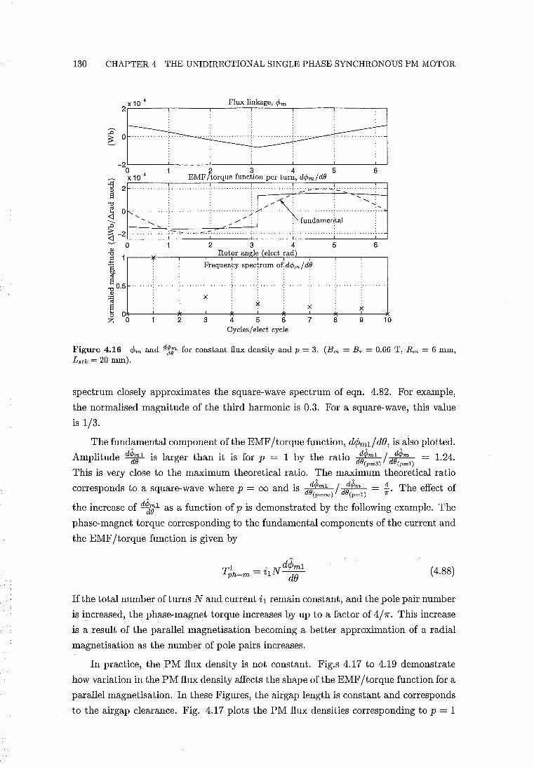
130 CHAPTER 4 THE UNIDIRECTIONAL SINGLE PHASE SYNCHRONOUS PM MOTOR
Flux linkage, <Pm
_2L-----~------~-------L------~------~------~ o 2 3 4 5 6 X 10⁻⁴ EMF /torque function per turn, d<pm / de I 2 ............. ; ................ ; ................ ; .............. ; .. .:.:..'-'.~-.~;'.; . .:..:...... . .. .
] 0 ___ <':' v.-<~ ........ ..... ~.>,~ ___ '- /' --1 ; fundamedtal
~-2L· ____ ~_~_-·_-·_~~·~_ .. · ____ ~ ____ ~ __ ~L-__ ~~ ~ 0 234 5 6 ~ Rotor angle (elect rad) ~ 1.---~---.----,-~~~==~~~~-,----.----,--~ 'i Frequen~y spectrum or: d<pm / dO
S "0 0.5 OJ
~
..
x
.. ..
~ O*---~---*----~--~--~--~*---~---*----L---* X X x
4 Z 0 2 3 5 6 7 8 9 10 Cycles / elect cycle
Figure 4.16 ¢m and ~ for constant flux density and p = 3. (Bm = Br = 0.66 T, Rm = 6 mm,
Lstk = 20 mm).
spectrum closely approximates the square-wave spectrum of eqn. 4.82. For example,
the normalised magnitude of the third harmonic is 0.3. For a square-wave, this value
is 1/3.
The fundamental component ofthe EMF /torque function, d¢ml/dO, is also plotted.
Amplitude dPd' me 1 is larger than it is for p = 1 by the ratio dde1>ml / ded¢)m = 1.24.
(p=3) (p=l)
This is very close to the maximum theoretical ratio. The maximum theoretical ratio
corresponds to a square-wave where p = 00 and is dt'Pml /ded1>m = i. The effect of (p=oo) (p=l) 1T'
the increase of d~el as a function of p is demonstrated by the following example. The
phase-magnet torque corresponding to the fundamental components of the current and
the EMF/torque function is given by
(4.88)
If the total number of turns N and current il remain constant, and the pole pair number
is increased, the phase-magnet torque increases by up to a factor of 4/7r. This increase
is a result of the parallel magnetisation becoming a better approximation of a radial
magnetisation as the number of pole pairs increases.
In practice, the PM flux density is not constant. Fig.s 4.17 to 4.19 demonstrate
how variation in the PM flux density affects the shape of the EMF/torque function for a
parallel magnetisation. In these Figures, the airgap length is constant and corresponds
to the airgap clearance. Fig. 4.17 plots the PM flux densities corresponding to p = 1
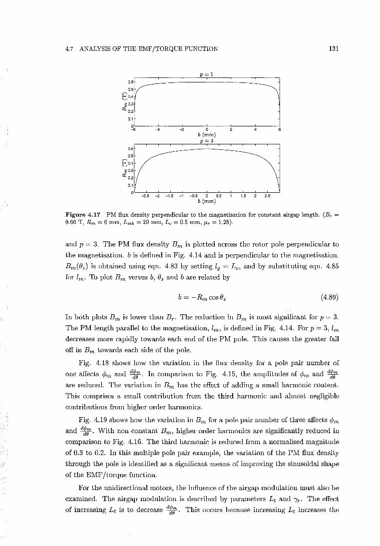
4.7 ANALYSIS OF THE EMF/TORQUE FUNCTION
O.S
0.5
EO.4
~ 0.3
~ 0.2
0.1
0 -s
O.S
0.5
EO.4
~0.3
~ 0.2
-4 -2
p=l
o b (mm) p=3
2 4 s
0.1
0L-_~2L.5--_2L-_~1L.5--_L1~_OL.5--LO~0~.5--~-1~.5--~2--2~.5~
b (mm)
131
Figure 4.17 PM flux density perpendicular to the magnetisation for constant airgap length. (Br = 0.66 T, Rm = 6 mm, Latk = 20 mm, Lc = 0.5 mm, J1r = 1.25).
and p = 3. The PM flux density Em is plotted across the rotor pole perpendicular to
the magnetisation. b is defined in Fig. 4.14 and is perpendicular to the magnetisation.
Em(Os) is obtained using eqn. 4.83 by setting 19 = L c , and by substituting eqn. 4.85
for lm. To plot Em versus b, Os and b are related by
b = -Rm cos Os (4.89)
In both plots Em is lower than Er . The reduction in Em is most significant for p = 3.
The PM length parallel to the magnetisation, lm, is defined in Fig. 4.14. For p = 3, lm
decreases more rapidly towards each end of the PM pole. This causes the greater fall
off in Em towards each side of the pole.
Fig. 4.18 shows how the variation in the flux density for a pole pair number of
one affects ¢m and dl;. In comparison to Fig. 4.15, the amplitudes of ¢m and dl; are reduced. The variation in Em has the effect of adding a small harmonic content.
This comprises a small contribution from the third harmonic and almost negligible
contributions from higher order harmonics.
Fig. 4.19 shows how the variation in Em for a pole pair number of three affects ¢m
and dl;. With non constant Em, higher order harmonics are significantly reduced in
comparison to Fig. 4.16. The third harmonic is reduced from a normalised magnitude
of 0.3 to 0.2. In this multiple pole pair example, the variation of the PM flux density
through the pole is identified as a significant means of improving the sinusoidal shape
of the EMF/torque function.
For the unidirectional motors, the influence of the air gap modulation must also be
examined. The airgap modulation is described by parameters L t and 'Yr. The effect
of increasing L t is to decrease dl;. This occurs because increasing L t increases the
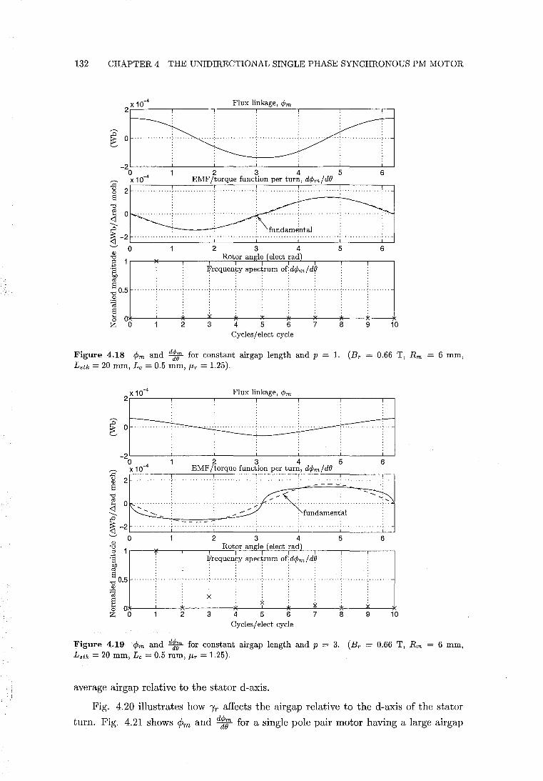
132 CHAPTER 4 THE UNIDIRECTIONAL SINGLE PHASE SYNCHRONOUS PM MOTOR
Flux linkage, ¢m
_2L-------L-------L-------L-------L-------L-------~
o X 10-4
:g '" 2 ........... . S
] ---
234 EMF/torque function per turn, d¢m/de
5 6
,D fundamental ~-2L-----~---··-··-··J····-··-··----~·-··-···-··-··-···~.·-·._ ... _ .. _ .. _. '_"L"_"'_"_"_" __ ~ ........ 0
'" "8 .~ S
"d 0.5
'" ~
234 Rotor angle (elect rad)
Frequen~y spectrum o{d¢m/d8
5 6
~ Ol~--~----~----~~·----*_--~~L---~----~~·----*_---~~·~--_* Z 0 2 3 4 5 6 7 8 9 10
Cycles / elect cycle
Figure 4.18 1>m and ~ for constant air gap length and p Lstk = 20 mm, Lc = 0.5 mm, /lr = 1.25).
1. (Br = 0.66 T, Rm
2 X 10⁻⁴
::0 0 ~
-2 0
? x 10-4
u 2 '"
Flux linkage, ¢m
23456 EMF /torque function per turn, d¢m / de
. . ........................ .. .... . .......... ~ . . . . . . . . . . . . . . . '. , - - - -'-S
I 0 " / ~ .~ ~ 'S\~~~d~~e~~~; ~ -2 ,--_~::=.=~=.-:-.=:-:-=. :-::.-::= .. : .. : .. '~"_" ._ .. .L., .. '_"_" '_"_" ._ .. ....J. .. _ .. __ --'-_ .. '_"_" '_"->-" '--l'
........ 0 234 5 6 ..gj Rotor angle (elect rad) ~ 1r----¥----,-----r-~~~~~~~r=L-_r----,---_,----,
.-::: Frequency spectrum o{d¢m/d8
t "d 0.5
'" ~ ~ Ol*---~---*--~----*---~---*--~~~*_--A---_*
)i( x ~ y
Z 0 2 3 4 5 6 7 8 9 10 Cycles / elect cycle
Figure 4.19 1>m and ~ for constant air gap length and p = 3. (Br = 0.66 T, Rm Lstk = 20 mm, Lc = 0.5 mm, /lr = 1.25).
average air gap relative to the stator d-axis.
6 mm,
6 mm,
Fig. 4.20 illustrates how "iT affects the airgap relative to the d-axis of the stator
turn. Fig. 4.21 shows ¢m and d1; for a single pole pair motor having a large airgap
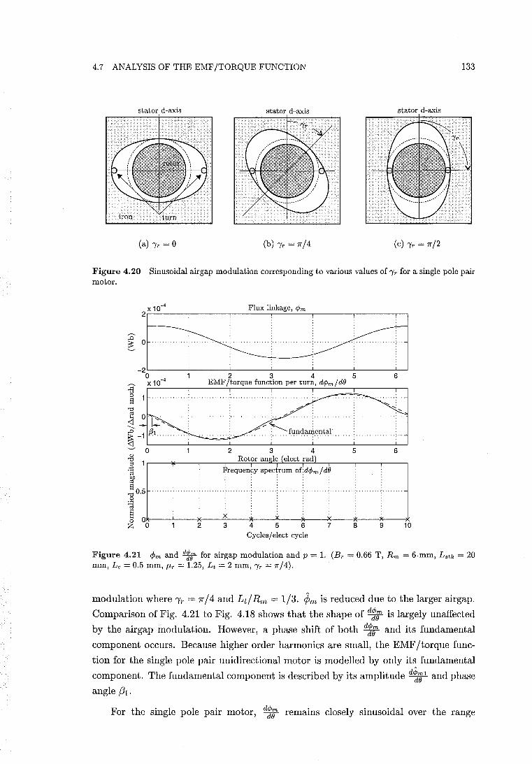
4.7 ANALYSIS OF THE EMF/TORQUE FUNCTION 133
stator d-axis stator d-axis stator d-axis
(a) "/r = 0 (b) "/r = 7r/4 (c) "/r = 7r/2
Figure 4.20 Sinusoidal airgap modulation corresponding to various values of "/r for a single pole pair motor.
Flux linkage, <Pm
~ 0
_2L-------L-------L-------L-------L-------~------~
o X 10-4
'"d ~ 0 ~ -... ~.~.~ .
.D 1
23456 EMF /torque function per turn, d<pm / dB
" ..
~ -1 .... ~ L-______ L-______ L-______ L-______ L-______ ~ ______ ~
~ 0 Q)
'"d ;;
.~ S
'"d 0.5 Q)
~
2 3 4 5 6 Rotor angle (elect rad)
Frequency spectrum o(d<pm/dO
E Ol*-__ ~ __ _*--~i~--*_--Jx~--*_--~~·~--w~·--~~__* ~O 2345678 9 10
Cycles / elect cycle
Figure 4.21 CPm and ~ for airgap modulation and p = 1. (Br = 0.66 T, Rm = 6mm, Lstk = 20 mm, Lc = 0.5 mm, J.£r = 1.25, Lt = 2 mm, "/r = 7r/4).
modulation where 'Yr = 1["/4 and Lt!Rm = 1/3. ¢m is reduced due to the larger airgap.
Comparison of Fig. 4.21 to Fig. 4.18 shows that the shape of d1; is largely unaffected
by the airgap modulation. However, a phase shift of both d1; and its fundamental
component occurs. Because higher order harmonics are small, the EMF/torque func
tion for the single pole pair unidirectional motor is modelled by only its fundamental
component. The fundamental component is described by its amplitude dtr;l and phase
angle (31.
For the single pole pair motor, d1; remams closely sinusoidal over the range
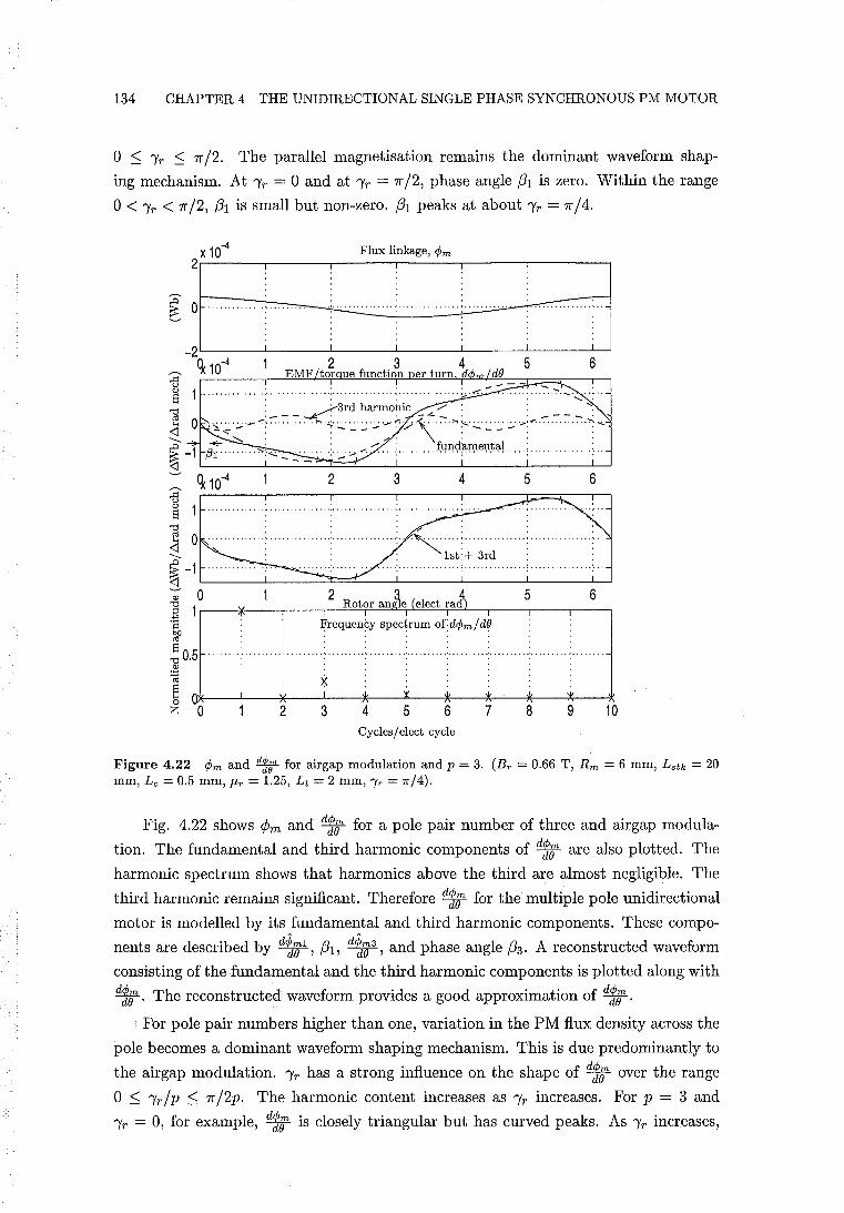
134 CHAPTER 4 THE UNIDIRECTIONAL SINGLE PHASE SYNCHRONOUS PM MOTOR
o ~ 'Yr ~ 1f /2. The parallel magnetisation remains the dominant waveform shap
ing mechanism. At 'Yr = 0 and at 'Yr = 1f /2, phase angle (31 is zero. Within the range
0< 'Yr < 1f/2, (31 is small but non-zero. (31 peaks at about 'Yr = 1f/4.
6 :s
Q)
8 ' ' ~ ___ ~3rd harmohic _.0<.::: : : ____ -: ~ 0 ~'~:'--::""""'" ''''<;':.:: '':':': ';"; ':':':/'\"'''' :"" :.:: :':':": ';...' '-":"'"" """ ":' '" ..c ...,.. : : ---: fundamental: : ~ -1 {3r''''''''''','' _ '~."~'~",";..'-.:-''''''' '"'',''''''''''''''':''''''''''''''';''''''''''''''','''
i 1 q 10
4
....................... : ......... 3 ............ 4.... . .... 5 ............ 6 ..
I 0 , .. " ... " .. , .: ...... ,."'.". ':"""""""';' ., l'~t '~. '3~~""""""""""" .:".
s; -1 ,,,"" '"'' "'" '" "."-:".,,.,,' ""':.".,," "."" ;".,," """ ,: "".,," ".".:-" <:] ';' 0 1 2 ~ II 5 6 "§ 1 Rotor ang1e (elect rad)
'8 Frequency spectrum ofd¢mld~ @
"0 0,5 Q)
~ X,'
~ OI%-__ -L __ ~~--~--~~--~y'----*---_w~'~~.~I', --~~~--~ Z 0 2 3 4 5 6 7 8 9 10
Cycles I elect cycle
Figure 4.22 CPm and ~ for airgap modulation and p = 3, (Br = 0,66 T, Rm = 6 mm, Lstk = 20 mm, Lc = 0,5 mm, J.tr = 1.25, Lt = 2 mm, "Ir = 1[/4),
Fig. 4.22 shows <Pm and d1; for a pole pair number of three and airgap modula
tion, The fundamental and third harmonic components of d1; are also plotted. The
harmonic spectrum shows that harmonics above the third are almost negligible. The
third harmonic remains significant. Therefore d1; for the multiple pole unidirectional
motor is modelled by its fundamental and third harmonic components. These compo
nents are described by d~Ol, (31, d~03, and phase angle (33. A reconstructed waveform
consisting of the fundamental and the third harmonic components is plotted along with
d1;. The reconstructed waveform provides a good approximation of d1; . For pole pair numbers higher than one, variation in the PM flux density across the
pole becomes a dominant waveform shaping mechanism. This is due predominantly to
the airgap modulation. 'Yr has a strong influence on the shape of d1; over the range
o ~ 'Yr/P ~ 1f/2p. The harmonic content increases as 'Yr increases. For p = 3 and
'Yr = 0, for example, d1r is closely triangular but has curved peaks. As 'Yr increases,
4.8 ANALYSIS OF THE PM RELUCTANCE TORQUE 135
d1; transforms into a flat topped trapezoid with rounded edges occurring at "Ir = 1[' /2p.
For the unidirectional motor, only a value of about "Ir = 1['/ 4p is of use. Only this
value achieves the desired PM reluctance torque displacement. The effects of the phase
shift and harmonics in d1; are addressed in sections 4.9 and 4.10.
4.8 ANALYSIS OF THE PM RELUCTANCE TORQUE
This section determines the PM reluctance torque of a unidirectional motor having an
arbitrary number of pole pairs. The aim of the analysis is to provide a fast 'ball-park'
estimate of the reluctance torque. In an identical manner to section 4.7.3.3, the rotor
poles consist of PM sectors and the airgap is modulated sinusoidally.
The energy method of section 3.5 is used to determine the PM reluctance torque.
The reluctance torque is calculated after first obtaining the stored field energy with all
windings de-energised, W(i = 0). The PM reluctance torque is given by eqn. 2.13:
T __ dW(i = 0) r - de
The stator iron is again assumed to be infinitely permeable such that the energy stored
in this region is negligible. The stored energy is then obtained from contributions from
the PM rotor and the airgap. These contributions are integrated over the respective
PM rotor and airgap volumes according to eqn. 3.3:
W(i = 0) = r wmdvm + r wadva iVm iVa where Wm and Wa are the energy density functions of the PM material and the airgap,
respectively. As discussed in section 4.7.3.1, the flux density within the PM material
is assumed to be parallel to the magnetisation. For a PM material modelled by a
linear major demagnetisation characteristic, the stored energy density is then given as
a function of the flux density by eqn. 3.4:
The approximations of the direction and magnitude of the PM flux density, described
in sections 4.7.3.1 and 4.7.3.2, allow an elementary expression for Bm to be obtained.
The stored energy density within the airgap is given by eqn. 3.2:
End effects are ignored such that the flux and energy densities are assumed to
remain constant in the axial direction. This allows the volume integration of the stored
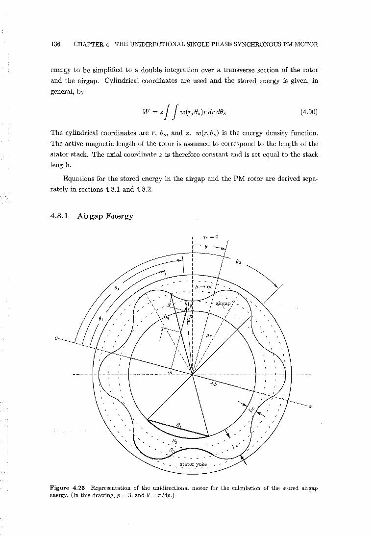
136 CHAPTER 4 THE UNIDIRECTIONAL SINGLE PHASE SYNCHRONOUS PM MOTOR
energy to be simplified to a double integration over a transverse section of the rotor
and the airgap. Cylindrical coordinates are used and the stored energy is given, in
general, by
W = z J J w(r, Os)r dr dOs (4.90)
The cylindrical coordinates are r, Os, and z. w(r, Os) is the energy density function.
The active magnetic length of the rotor is assumed to correspond to the length of the
stator stack. The axial coordinate z is therefore constant and is set equal to the stack
length.
Equations for the stored energy in the air gap and the PM rotor are derived sepa
rately in sections 4.8.1 and 4.8.2.
4.8.1 Airgap Energy
o
Figure 4.23 Representation of the unidirectional motor for the calculation of the stored airgap energy. (In this drawing, p = 3, and e = 7r / 4p.)
4.8 ANALYSIS OF THE PM RELUCTANCE TORQUE 137
The stored energy corresponding to the airgap of the unidirectional motor is derived
with reference to Fig. 4.23. Fig. 4.23 is almost identical to Fig. 4.14 except that the
PM reluctance torque displacement angle 'Yr is set to zero and the stator conductors are
not shown. The simplification obtained by setting 'Yr = 0 does not effect the magnitude
nor the shape of the PM reluctance torque. The integration of the airgap energy is
performed in the airgap region above a single PM rotor pole sector. The total airgap
energy is then obtained by multiplying the integrated energy by the number of poles.
First, airgap densities Ba and Wa are derived as a function of coordinates rand (}s. At
the rotor pole surface the airgap flux density is given according to eqn. 4.75 by
(4.91)
The flux density within the PM sector lying parallel to the magnetisation, Bm , is
derived identically to section 4.7.3. Bm is obtained from eqn.s 4.83, 4.84, and 4.85 with
'Yr = O.
Expressions for the flux density throughout the airgap and PM rotor volumes,
and therefore also the corresponding energy densities, are more accurate if div B = O.
Cross-sections of surfaces Sl, S2, and S3 are drawn in Fig. 4.23. Each surface spans
the pitch of the pole. Surface Sl spans the surface of the PM sector perpendicular to
the PM flux density Bm. S2 spans the airgap surface of the PM sector perpendicular
to the airgap flux density Ba. S3 spans the airgap surface of the stator yoke. If
Is B . n da = constant (4.92)
for each of these surfaces, div B = 0 is likely to be satisfied in the PM sector and in
the airgap. Substitution of eqn.s 4.91 and 4.71 into eqn. 4.92 demonstrates that eqn.
4.91 satisfies div B = 0 at the airgap surface of the PM sector: the pole surface flux is
equal to the flux within the PM sector.
An expression for Ba = Ba(r, (}s) corresponding to any coordinate within the airgap
must also satisfy div B = O. For the element of airgap area defined by
(4.93)
the radial flux density is parallel to the unit normal vector such that B . n = Ba(r, (}s).
B . n da is then equal to Ba(r, (}s)Lstkr d(}s. If (}s and dBs are held constant, div B = 0
is satisfied if
(4.94)
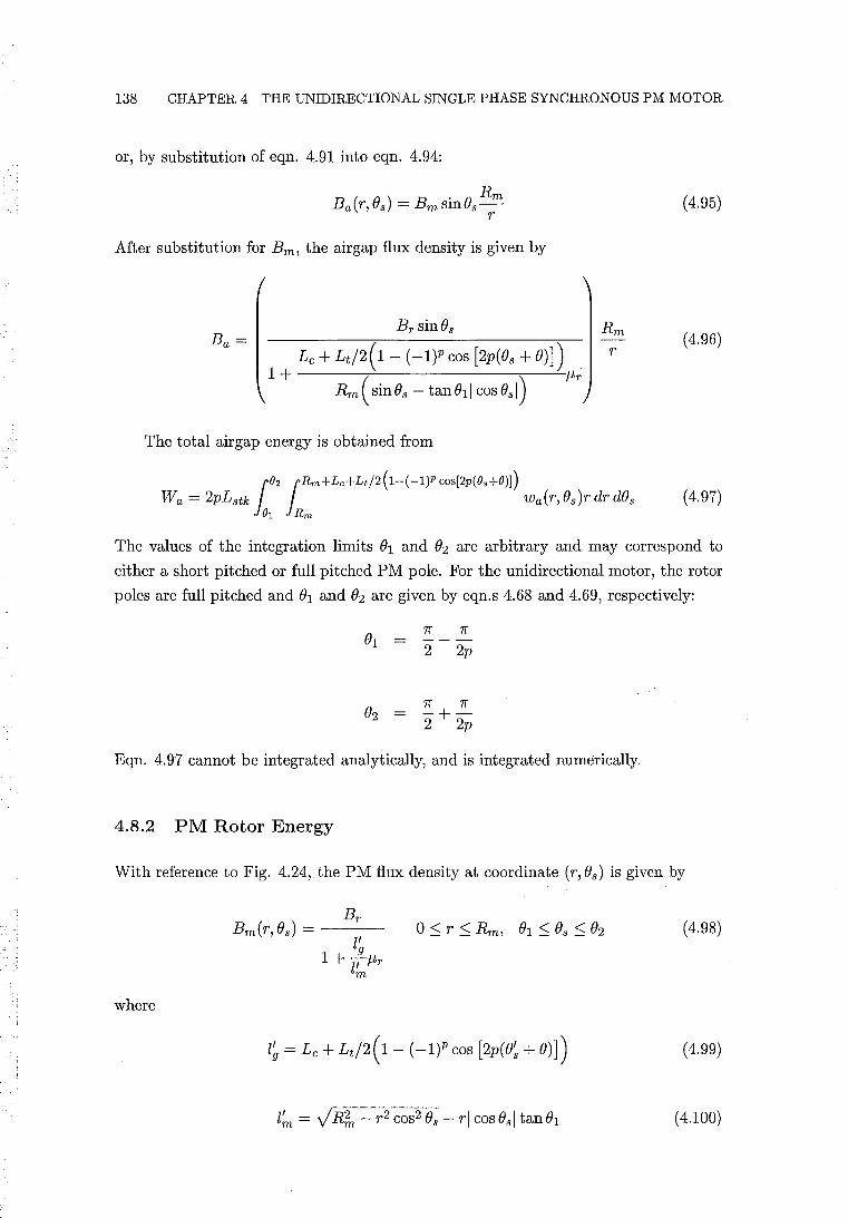
138 CHAPTER 4 THE UNIDIRECTIONAL SINGLE PHASE SYNCHRONOUS PM MOTOR
or, by substitution of eqn. 4.91 into eqn. 4.94:
(4.95)
After substitution for Bm , the airgap flux density is given by
(4.96)
The total airgap energy is obtained from
(4.97)
The values of the integration limits 01 and O2 are arbitrary and may correspond to
either a short pitched or full pitched PM pole. For the unidirectional motor, the rotor
poles are full pitched and 01 and O2 are given by eqn.s 4.68 and 4.69, respectively:
2p
1f 7r O2 = - +-
2 2p
Eqn. 4.97 cannot be integrated analytically, and is integrated numerically.
4.8.2 PM Rotor Energy
With reference to Fig. 4.24, the PM flux density at coordinate (r, Os) is given by
(4.98)
where
(4.99)
(4.100)
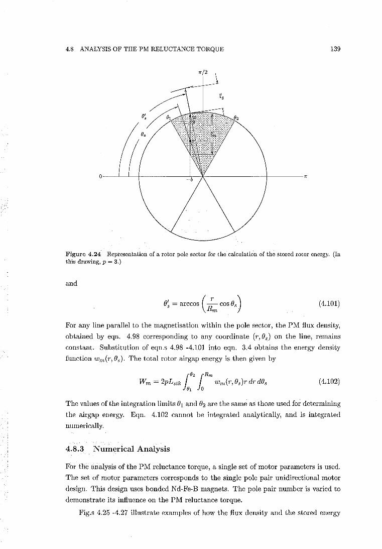
4,8 ANALYSIS OF THE PM RELUCTANCE TORQUE 139
7r/2
O----~~-r----------~~~--------------_r--------7r
Figure 4.24 Representation of a rotor pole sector for the calculation of the stored rotor energy, (In this drawing, p = 3,)
and
()~ = arccos (;m cos () s ) (4.101)
For any line parallel to the magnetisation within the pole sector, the PM flux density,
obtained by eqn. 4.98 corresponding to any coordinate (r, ()s) on the line, remains
constant. Substitution of eqn,s 4.98 -4.101 into eqn. 3.4 obtains the energy density
function wm(r, ()s), The total rotor airgap energy is then given by
(4.102)
The values of the integration limits ()1 and ()2 are the same as those used for determining
the airgap energy. Eqn. 4.102 cannot be integrated analytically, and is integrated
numerically.
4.8.3 Numerical Analysis
For the analysis of the PM reluctance torque, a single set of motor parameters is used.
The set of motor parameters corresponds to the single pole pair unidirectional motor
design. This design uses bonded Nd-Fe-B magnets. The pole pair number is varied to
demonstrate its influence on the PM reluctance torque.
Fig.s 4.25 -4.27 illustrate examples of how the flux density and the stored energy
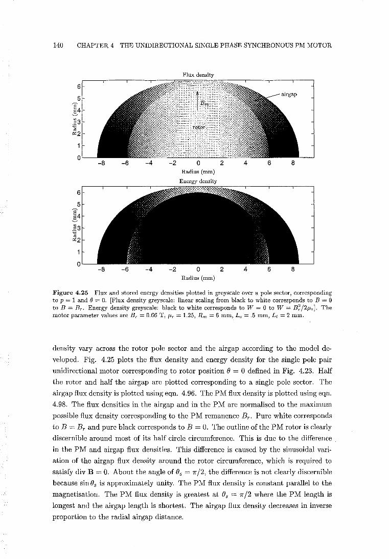
140 CHAPTER 4 THE UNIDIRECTIONAL SINGLE PHASE SYNCHRONOUS PM MOTOR
Flux density
6
5
14 .83 ] ~2
0 -8 -6 -4 -2 0 2 6 8
Radius (mm)
Energy density
6
5
14 .83 "0 <d ~2
0 -8 -6 -4 -2 0 2 4 6 8
Radius (mm)
Figure 4.25 Flux and stored energy densities plotted in greyscale over a pole sector, corresponding to p = 1 and () = O. [Flux density greyscale: linear scaling from black to white corresponds to B = 0 to B = B T • Energy density greyscale: black to white corresponds to W = 0 to W = B;/2J.l-oj. The motor parameter values are Br = 0.66 T, J.l-r = 1.25, Rm = 6 mm, Lc '= .5 mm, Lt = 2 mm.
density vary across the rotor pole sector and the airgap according to the model de
veloped. Fig. 4.25 plots the flux density and energy density for the single pole pair
unidirectional motor corresponding to rotor position () = 0 defined in Fig. 4.23. Half
the rotor and half the airgap are plotted corresponding to a single pole sector. The
airgap flux density is plotted using eqn. 4.96. The PM flux density is plotted using eqn.
4.98. The flux densities in the airgap and in the PM are normalised to the maximum
possible flux density corresponding to the PM remanence B r . Pure white corresponds
to B = Br and pure black corresponds to B = O. The outline of the PM rotor is clearly
discernible around most of its half circle circumference. This is due to the difference
in the PM and airgap flux densities. This difference is caused by the sinusoidal vari
ation of the airgap flux density around the rotor circumference, which is required to
satisfy div B = O. About the angle of ()s = 7r /2, the difference is not clearly discernible
because sin()s is approximately unity. The PM flux density is constant parallel to the
magnetisation. The PM flux density is greatest at ()s = 7r /2 where the PM length is
longest and the airgap length is shortest. The airgap flux density decreases in inverse
proportion to the radial airgap distance.
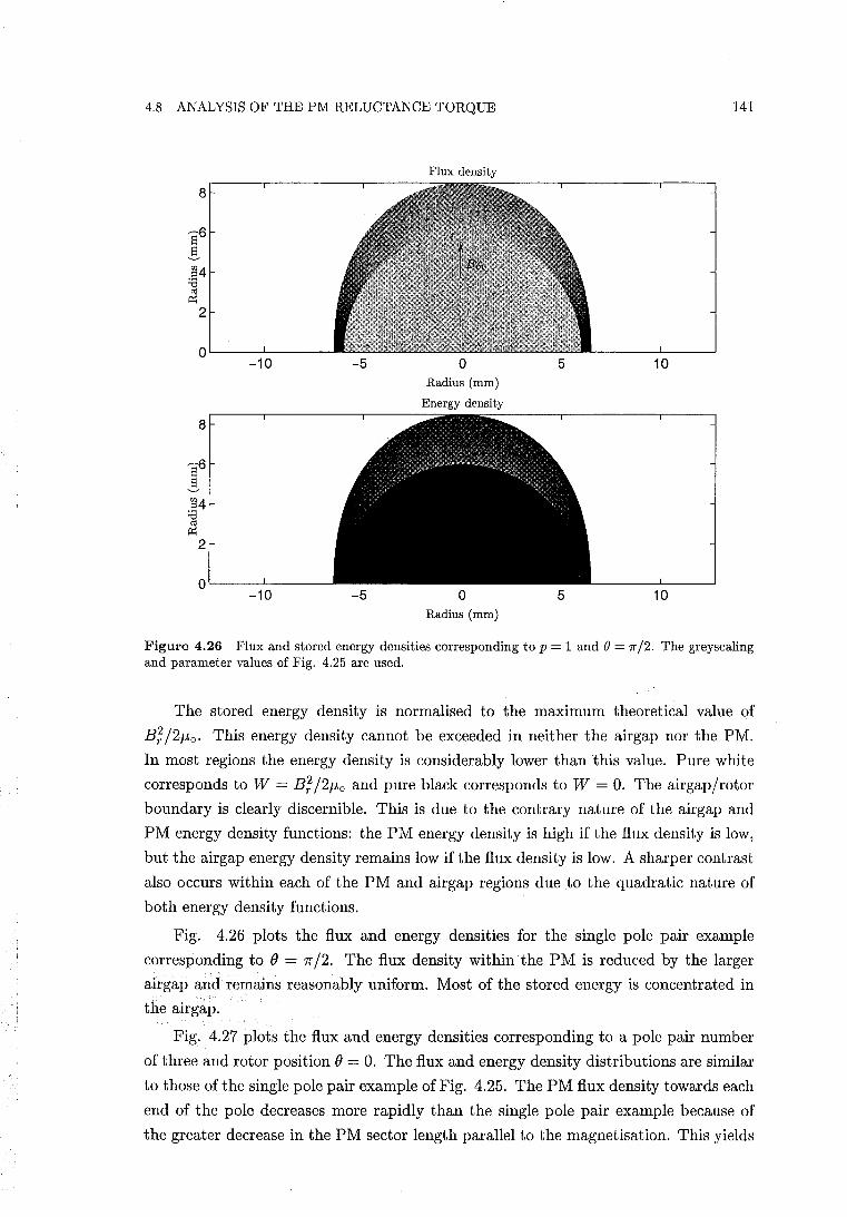
4.8 ANALYSIS OF THE PM RELUCTANCE TORQUE 141
Flux density
8
sU 5 gj4 :e
cO 0:;
2
0 -10 -5 0 5 10
Radius (mm)
Energy density
8
sU 5 gj4 :e
cO 0:;
2
0 -10 -5 0 5 10
Radius (mm)
Figure 4.26 Flux and stored energy densities corresponding to p = 1 and () = 7r /2. The greyscaling and parameter values of Fig. 4.25 are used.
The stored energy density is normalised to the maximum theoretical value of
B;/2/-lo , This energy density cannot be exceeded in neither the air gap nor the PM.
In most regions the energy density is considerably lower than this value. Pure white
corresponds to W = B; /2/-lo and pure black corresponds to W = O. The airgap/rotor
boundary is clearly discernible. This is due to the contrary nature of the airgap and
PM energy density functions: the PM energy density is high if the flux density is low,
but the airgap energy density remains low if the flux density is low. A sharper contrast
also occurs within each of the PM and air gap regions due to the quadratic nature of
both energy density functions.
Fig. 4.26 plots the flux and energy densities for the single pole pair example
corresponding to () = 7r /2. The flux density within the PM is reduced by the larger
airgap and remains reasonably uniform. Most of the stored energy is concentrated in
the airgap.
Fig. 4.27 plots the flux and energy densities corresponding to a pole pair number
of three and rotor position () = O. The flux and energy density distributions are similar
to those of the single pole pair example of Fig. 4.25. The PM flux density towards each
end of the pole decreases more rapidly than the single pole pair example because of
the greater decrease in the PM sector length parallel to the magnetisation. This yields
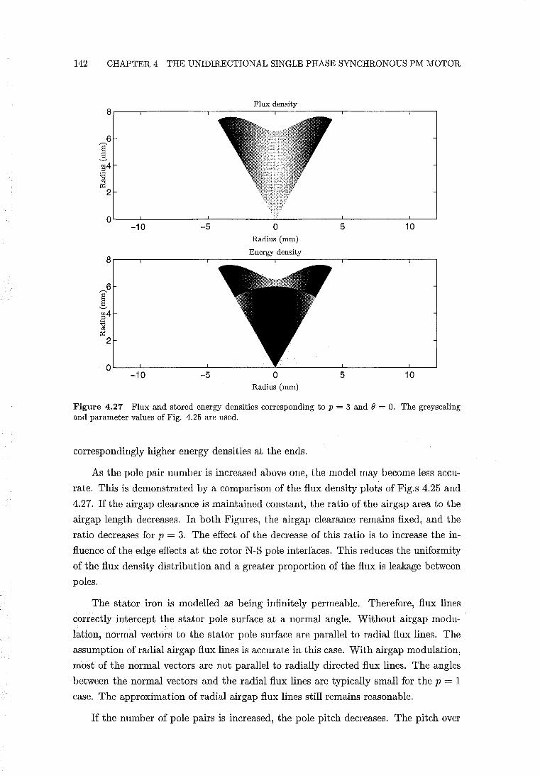
142 CHAPTER 4 THE UNIDIRECTIONAL SINGLE PHASE SYNCHRONOUS PM MOTOR
8
6 S 5 ~4 ] ~
2
0 -10
8
6 S 5 ~4 ;a oj
~ 2
0 -10
-5
-5
Flux density
o Radius (mm)
Energy density
o Radius (mm)
5 10
5 10
Figure 4.27 Flux and stored energy densities corresponding to p = 3 and e = O. The greyscaling and parameter values of Fig. 4.25 are used.
correspondingly higher energy densities at the ends.
As the pole pair number is increased above one, the model may become less accu
rate. This is demonstrated by a comparison of the flux density plots of Fig.s 4.25 and
4.27. If the airgap clearance is maintained constant, the ratio of the airgap area to the
airgap length decreases. In both Figures, the airgap clearance remains fixed, and the
ratio decreases for p = 3. The effect of the decrease of this ratio is to increase the in
fluence of the edge effects at the rotor N-S pole interfaces. This reduces the uniformity
of the flux density distribution and a greater proportion of the flux is leakage between
poles.
The stator iron is modelled as being infinitely permeable. Therefore, flux lines
correctly intercept the stator pole surface at a normal angle. Without airgap modu
lation, normal vectors to the stator pole surface are parallel to radial flux lines. The
assumption of radial airgap flux lines is accurate in this case. With airgap modulation,
most of the normal vectors are not parallel to radially directed flux lines. The angles
between the normal vectors and the radial flux lines are typically small for the p = 1
case. The approximation of radial airgap flux lines still remains reasonable.
If the number of pole pairs is increased, the pole pitch decreases. The pitch over
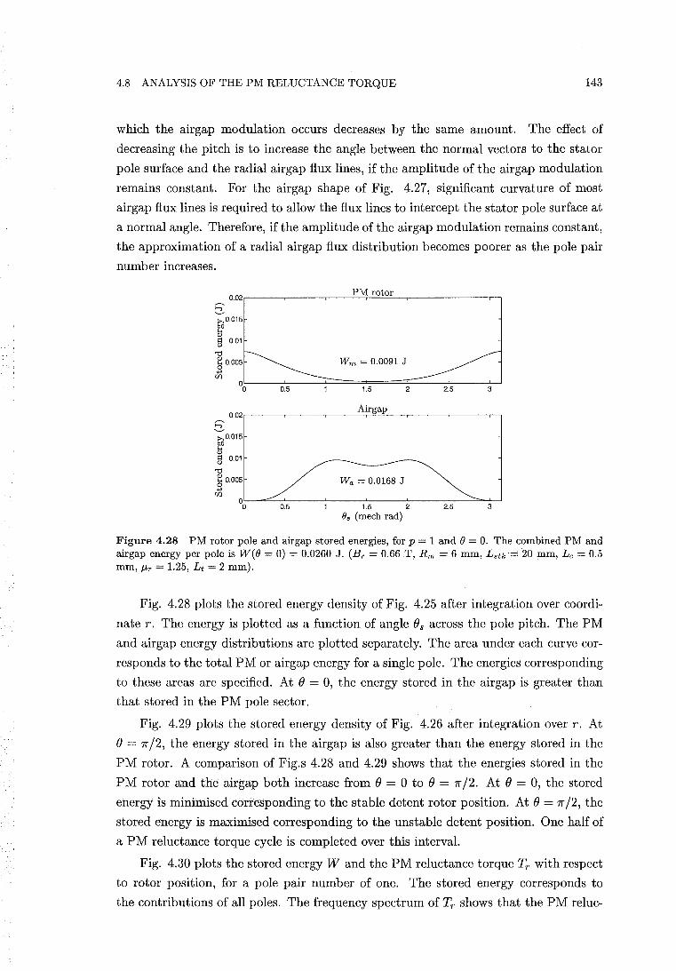
4.8 ANALYSIS OF THE PM RELUCTANCE TORQUE 143
which the airgap modulation occurs decreases by the same amount. The effect of
decreasing the pitch is to increase the angle between the normal vectors to the stator
pole surface and the radial airgap flux lines, if the amplitude of the airgap modulation
remains constant. For the airgap shape of Fig. 4.27, significant curvature of most
airgap flux lines is required to allow the flux lines to intercept the stator pole surface at
a normal angle. Therefore, if the amplitude of the airgap modulation remains constant,
the approximation of a radial air gap flux distribution becomes poorer as the pole pair
number increases.
PM rotor 0.02.-----,----.----"-..:::..:;-==--,----.----,--,
1:;)0.015
~ § 0.01
"0 ~ 0.005 o +'
Wm = 0.0091 J
UJ °0L--~~-~~========~~-~--~
0.5 1.5 2 2.5 3
5: Airgap
0.02,-----,----.---::..:::r=--,----.----,--,
1:;)0.015
~ § 0.01
"0 ~ 0.005 +' UJ
Wa = 0.0168 J
~L-~~0.~5--J---1~.5~--2~-~2.~5-~~3~
O. (mech rad)
Figure 4.28 PM rotor pole and airgap stored energies, for p = 1 and 8 = O. The combined PM and airgap energy per pole is W(8 = 0) = 0.0260 J. (Br = 0.66 T, Rm = 6 mm, L.tk=' 20 mm, Lc = 0.5 mm, fjr = 1.25, L t = 2 mm).
Fig. 4.28 plots the stored energy density of Fig. 4.25 after integration over coordi
nate r. The energy is plotted as a function of angle () s across the pole pitch. The PM
and airgap energy distributions are plotted separately. The area under each curve cor
responds to the total PM or airgap energy for a single pole. The energies corresponding
to these areas are specified. At () = 0, the energy stored in the airgap is greater than
that stored in the PM pole sector.
Fig. 4.29 plots the stored energy density of Fig. 4.26 after integration over r. At
() = 7r /2, the energy stored in the airgap is also greater than the energy stored in the
PM rotor. A comparison of Fig.s 4.28 and 4.29 shows that the energies stored in. the
PM rotor and the airgap both increase from () = ° to () = 7r /2. At () = 0, the stored
energy is minimised corresponding to the stable detent rotor position. At () = 7r /2, the
stored energy is maximised corresponding to the unstable detent position. One half of
a PM reluctance torque cycle is completed over this interval.
Fig. 4.30 plots the stored energy Wand the PM reluctance torque Tr with respect
to rotor position, for a pole pair number of one. The stored energy corresponds to
the contributions of all poles. The frequency spectrum of Tr shows that the PM reluc-
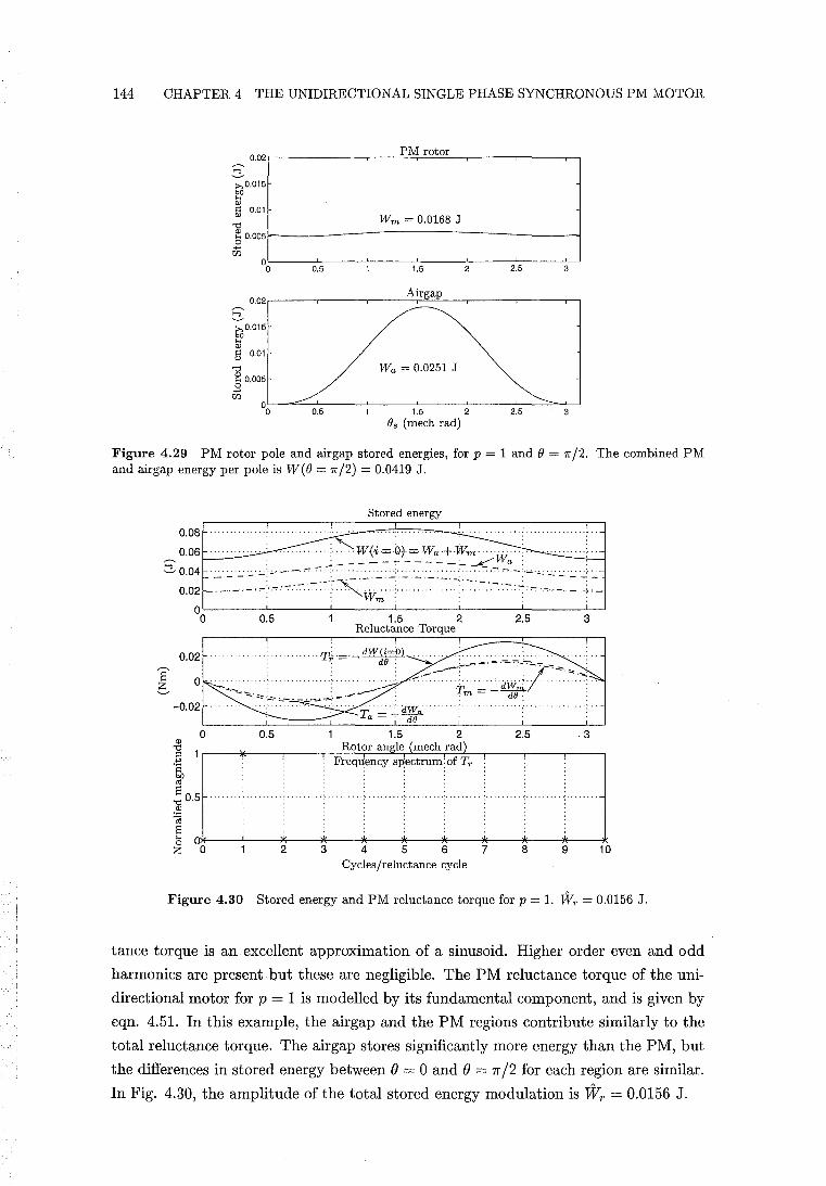
144 CHAPTER 4 THE UNIDIRECTIONAL SINGLE PHASE SYNCHRONOUS PM MOTOR
0.02r---,---,.--..c:P'-'M~r-"'ot""o:.::.r-,.---..-__ ,..-,
gO.015
51 5 0.01 Wm = 0.0168 J
]0.005~----------------------------~ "" en
~L---OL.5--~---J1.-5---2~-~2~.5--~3~
Airgap 0.02,.---,---,.----=-:::r"=--,----,----.-,
gO.015
51 5 0.01
"d ~ 0.005 o "" en
Wa = 0.0251 J
°0L-~~OL.5--~---J1.5---2~--2~.5-~~3~
Os (mech rad)
Figure 4.29 PM rotor pole and air gap stored energies, for p = 1 and 0 = 7r /2. The combined PM and airgap energy per pole is W(O = 7r/2) = 0.0419 J.
Stored energy
O 08r=~~~~:=:;::.+.===:~~·~· .. ~ .... = .... ~ .. ~ .... ~ .... = .... T.':] ... . 0.06'--_
SO.04
0.02 OL-___ L-___ L-___ L-___ L-___ L-___ ~
o 0.5 1.5 2 2.5 3 Reluctance Torque
0.02
o
0.5 1.5 2 2.5 3 Rotor angle (mech rad)
Frequency spectrum:of Tr
2 3 4 5 6 7 8 9 10 Cycles/reluctance cycle
Figure 4.30 Stored energy and PM reluctance torque for p = 1. TV, = 0.0156 J.
tance torque is an excellent approximation of a sinusoid. Higher order even and odd
harmonics are present but these are negligible. The PM reluctance torque of the uni
directional motor for p = 1 is modelled by its fundamental component, and is given by
eqn. 4.51. In this example, the airgap and the PM regions contribute similarly to the
total reluctance torque. The airgap stores significantly more energy than the PM, but
the differences in stored energy between e = 0 and e = 7r /2 for each region are similar.
In Fig. 4.30, the amplitude of the total stored energy modulation is Wr = 0.0156 J.
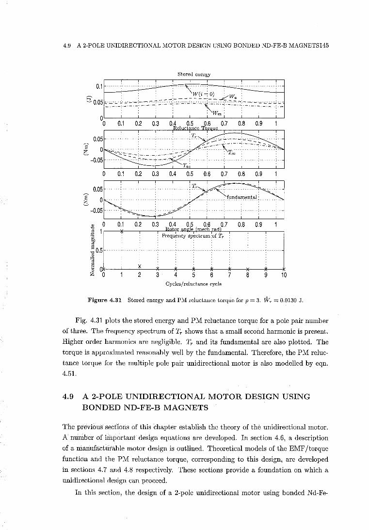
4.9 A 2-POLE UNIDIRECTIONAL MOTOR DESIGN USING BONDED ND-FE-B MAGNETS145
Stored energy
so::~ ••••••••• ::::~~t:L~i~=~~:::;Ej •••••••••••• ~::1 . 1-~-~~~'-"~:~~~~::":"~,:-'-1-'-'~-;~~':'~~-_ O~--~--~--~--~--~--~--~--~--~--~~
o 0.1 0.2 0.3 0.4 0.5 0.6 0.7 0.8 0.9 Reluctance Tor ue
0.05 ... '," ............. , ....... , ........ , .. 7r .. ,
~ 0 -0.05
';":':'::':~'~',- -,-;.;..':,' , --. - . - . - , - , - . -' ,-,....,..
. ...................... " ............. , ..... ", .. :: .~.-.-7 ......
o 0.1 0.2 0.3 0.4 0.5 0.6 0.7 0.8 0.9
0.05
~ 0 -0.05 .... ~.'" .. : ........ .' ........ ~ -o..~.: ....
, , ..... : L-~~~I'-~L--L~ __ ~-L __ L-~
Q) 0 0.1 0.2 0.3 0.4 0.5 0.6 0.7 0.8 0.9 ] 1r-__ ~ __ -, ____ r-~R~ot~o~r~an~1~~ljeT(~Jm~e~ch~ra~d~),-__ -, ____ r---. ;~ : : Frequency SPectrum :of Tr :
S "0 0.5 Q)
1 Ol~---L---~~·~--*~·--~~--~---~*'--~~~--~~~--~*'--~ ZO 23456789 10
Cycles/reluctance cycle
Figure 4.31 Stored energy and PM reluctance torque for p = 3. TVr = 0.0130 J.
Fig. 4.31 plots the stored energy and PM reluctance torque for a pole pair number
of three. The frequency spectrum of Tr shows that a small second harmonic is present.
Higher order harmonics are negligible. Tr and its fundamental are also plotted. The
torque is approximated reasonably well by the fundamental. Therefore, the PM reluc
tance torque for the multiple pole pair unidirectional motor is also modelled by eqn.
4.51.
4.9 A 2-POLE UNIDIRECTIONAL MOTOR DESIGN USING BONDED ND-FE-B MAGNETS
The previous sections of this chapter establish the theory of the unidirectional motor.
A number of important design equations are developed. In section 4.6, a description
of a manufacturable motor design is outlined. Theoretical models of the EMF/torque
function and the PM reluctance torque, corresponding to this design, are developed
in sections 4.7 and 4.8 respectively. These sections provide a foundation on which a
unidirectional design can proceed.
In this section, the design of a 2-pole unidirectional motor using bonded Nd-Fe-
146 CHAPTER 4 THE UNIDIRECTIONAL SINGLE PHASE SYNCHRONOUS PM MOTOR
B rotor magnets is described. Estimates of performance parameters, and parameters
required for simulation, are calculated. The motor is then simulated using the equations
of motion to evaluate the success of the design. The aim is to produce a 'ballpark' design
which provides a starting point for experimental investigation.
The design described in this section is the result of a number of design iterations.
This began with a ferrite rotor design, which was then replaced with a Nd-Fe-B design.
Various rotor diameters were tried for each of these PM materials. The success of each
of these designs was determined by simulation. During this iterative design process,
eqn. 4.66 emerged as a critical tool for estimating the success of a design in terms of
attaining sufficient backward instability:
> 1
The parameters of the backward instability ratio are obtained from only the design
of the rotor and the rotor airgap. Wr is obtained by integrating the stored energy
over only the volume of the rotor and the airgap. The moment of inertia of the rotor,
Jr , contributes most significantly to the total inertia, J. An estimate of J can then
be made by only considering the dimensions of the rotor and the density of the PM
material used. Therefore, it is not necessary to begin the design of the stator until a
satisfactory backward instability ratio has been obtained.
A 50 Hz supply frequency is selected, and p = 1. The selection of the rotor diameter
Dr affects both Jr and Wr. Eqn. 4.67 shows that Jr ex: D;. Wr is proportional to
the rotor volume, such that Wr ex: D;. The backward instability ratio· is therefore
proportional to the inverse square of the rotor diameter. A rotor diameter of Dr = 12
mm is selected for this design. The bonded Nd-Fe-B magnets specified in section 3.3.2.1
are used. A value of Br = 0.66 T is used corresponding to an operating temperature of
60° C. As shown in section 3.6, Wr is proportional to the square of B r. It then follows
that
(4.103)
For single pole pair unidirectional motors with larger rotor diameters, higher grades
of PM material may be required. An airgap modulation of Lt = 2 mm is selected
with an airgap clearance of Lc = 0.5 mm. These values are selected such that the
approximations made regarding the PM field remain reasonable. The shape and scale
of the airgap relative to the rotor, corresponding to these values, is illustrated by Fig.
4.25. An axial rotor length of Lr = 20 mm is selected. The stack length is set equal to
the rotor length, in accordance with the practice that rare earth magnets normally do
not use overhang [Hendershot and Miller 1994, p. 3-23].
The PM reluctance torque corresponding to these parameters is plotted in Fig.
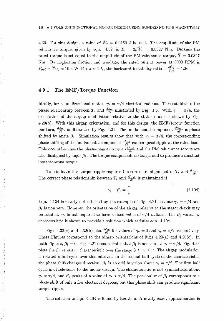
4.9 A 2-POLE UNIDIRECTIONAL MOTOR DESIGN USING BONDED ND-FE-B MAGNETS147
4.30. For this design, a value of Wr = 0.0163 J is used. The amplitude of the PM
reluctance torque, given by eqn. 4.52, is Tr = 2pWr = 0.0327 Nm. Because the
rated torque is set equal to the amplitude of the PM reluctance torque, T = 0.0327
Nm. By neglecting friction and windage, the rated output power at 3000 RPM is
Pout = TWe = 10.3 W. For J = 2Jr , the backward instability ratio is 4JWi = 1.36. We
4.9.1 The EMF/Torque Function
Ideally, for a unidirectional motor, 'Yr = 7f / 4 electrical radians. This establishes the
phase relationship between Tr and d~ff illustrated by Fig. 1.6. With 'Yr = 7f /4, the
orientation of the airgap modulation relative to the stator d-axis is shown by Fig.
4.20(b). With this air gap orientation, and for this design, the EMF/torque function
per turn, d1;, is illustrated by Fig. 4.21. The fundamental component d~el is phase
shifted by angle (31. Simulation results show that with 'Yr = 7f / 4, the corresponding
phase shifting of the fundamental component d~t causes speed ripple at the rated load.
This occurs because the phase-magnet torque i d~Vf and the PM reluctance torque are
also disaligned by angle (31. The torque components no longer add to produce a constant
instantaneous torque.
To eliminate this torque ripple requires the correct re-alignment of Tr and d~'31.
The correct phase relationship between Tr and d~W 1 is maintained if
7f 'Yr - (31 = -
4 (4.104)
Eqn. 4.104 is clearly not satisfied by the example of Fig. 4.21 because 'Yr = 7f / 4 and
(31 is non zero. However, the orientation of the airgap relative to the stator d-axis may
be rotated. 'Yr is not required to have a fixed value of 7f / 4 radians. The (31 versus 'Yr
characteristic is shown to provide a solution which satisfies eqn. 4.104.
Fig.s 4.32(a) and 4.32(b) plot d1; for values of'Yr = 0 and 'Yr = 7f/2, respectively.
These Figures correspond to the airgap orientations of Fig.s 4.20(a) and 4.20(c). In
both Figures, (31 = O. Fig. 4.21 demonstrates that (31 is non zero at 'Yr = 7f / 4. Fig. 4.33
plots the (31 versus 'Yr characteristic over the range 0 S; 'Yr S; 7f. The air gap modulation
is rotated a full cycle over this interval. In the second half cycle of the characteristic,
the phase shift changes direction. (31 is an odd function about 'Yr = 7f /2. The first half
cycle is of relevance to the motor design. The characteristic is not symmetrical about
'Yr = 7f / 4, and (31 peaks at a value of 'Yr > 7f / 4. The peak value of (31 corresponds to a
phase shift of only a few electrical degrees, but this phase shift can produce significant
torque ripple.
The solution to eqn. 4.104 is found by iteration. A nearly exact approximation is
148 CHAPTER 4 THE UNIDIRECTIONAL SINGLE PHASE SYNCHRONOUS PM MOTOR
X 10-4
-1 -
2 3 4 5 Rotor angle (elect rad)
2 3 4 5 Rotor angle (elect rad)
(a) ,T = O. (b) ,T = 7T/2.
Figure 4.32 EMF/torque function per turn, ~.
6.61- -----6
4 ---
... u Q)
~ <5'._2
-4
-6
-8 0 20 80 100 120 140 160 180
"IT (elect deg)
Figure 4.33 (31 versus ,T'
found using a single iteration. This first iteration is given by
I'~ = ~ + (31 (1'1' = i) (4.105)
where the phase shift (31 occuring at 1'1' = 7r / 4 is added to 1'1" If the characteristic is
nearly constant over the interval between 1'1' and I'~, then the new value of (31 given
by (3i b~) is nearly the same as the old value (31 b1' = 7r / 4). This is demonstrated in
Fig. 4.33. Therefore, the angle of the airgap modulation can be increased to correctly
align the PM reluctance torque to the EMF/torque function, without causing further
misalignment.
4.9 A 2-POLE UNIDIRECTIONAL MOTOR DESIGN USING BONDED ND-FE-B MAGNETS149
The new value "I~ is used in the design. The magnitude of d¢Z;l decreases as "Ir
increases over the range 0 ::; "Ir ::; 7r /2. This occurs because the stator d-axis airgap
length increases. Because "I~ > "Ir, the magnitude of d¢Z;l is reduced. However, in this
design the reduction in d~t is not significant. The original values of amplitude dt"B 1
and (31 are retained. However, the stable rotor rest position now occurs at B = "I~.
The amplitude of the fundamental component of the PM flux linkage is given by
(4.106)
where n = number of turns per pole.
Km is referred to as the PM flux linkage constant and is defined by
(4.107)
where
em PM flux linkage factor. This is defined as the fraction of the PM
flux linking a stator turn.
¢m1 amplitude of the fundamental component of the PM flux linkage
per turn (assuming no leakage)
In this analysis, ¢m1 is obtained from
;;, 1 = ~ d¢m1 . 'Pm p dB (4.108)
The fundamental amplitude dt"B1 is obtained from the frequency analysis of the
EMF /torque function. The single pole pair motor is drawn in Fig. 4.34. In the
designs of Fig.s 4.34 and 1.2(b), the PM flux leakage is exacerbated by the absence
of slot openings. For these designs, the PM flux leakage is typically up to 20%. A
corresponding value of em = 0.8 is used for the single pole pair design.
For a motor having an arbitrary number of pole pairs, the EMF/torque function
is given by
dAm A A
dB = PAm 1 sin(pB - (31) + 3PAm3 sin(3pB - (33) (4.109)
where
.\m3 amplitude of the third harmonic component of the PM flux linkage
(33 phase angle of the third harmonic
Angles (31 and (33 are specified in electrical units. A single pole pair motor is modelled
by setting .\m3 to zero. To simulate a unidirectional motor, eqn. 4.109 is substituted
into state eqn.s 4.53 and 4.54, replacing the term P.\m sin(pB).
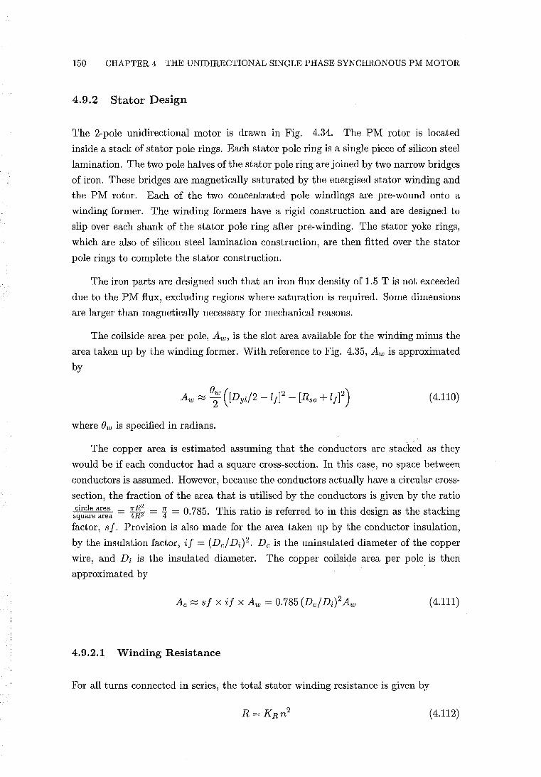
150 CHAPTER 4 THE UNIDIRECTIONAL SINGLE PHASE SYNCHRONOUS PM MOTOR
4.9.2 Stator Design
The 2-pole unidirectional motor is drawn in Fig. 4.34. The PM rotor is located
inside a stack of stator pole rings. Each stator pole ring is a single piece of silicon steel
lamination. The two pole halves of the stator pole ring are joined by two narrow bridges
of iron. These bridges are magnetically saturated by the energised stator winding and
the PM rotor. Each of the two concentrated pole windings are pre-wound onto a
winding former. The winding formers have a rigid construction and are designed to
slip over each shank of the stator pole ring after pre-winding. The stator yoke rings,
which are also of silicon steel lamination construction, are then fitted over the stator
pole rings to complete the stator construction.
The iron parts are designed such that an iron flux density of 1.5 T is not exceeded
due to the PM flux, excluding regions where saturation is required. Some dimensions
are larger than magnetically necessary for mechanical reasons.
The coils ide area per pole, Aw , is the slot area available for the winding minus the
area taken up by the winding former. With reference to Fig. 4.35, Aw is approximated
by
(4.110)
where Ow is specified in radians.
The copper area is estimated assuming that the conductors are stacked as they
would be if each conductor had a square cross-section. In this case, no space between
conductors is assumed. However, because the conductors actually have a circular cross
section, the fraction of the area that is utilised by the conductors is given by the ratio
circle area = 7r R2 = Z!:. = 0 785 This ratio is referred to in this design as the stacking square area 4R2 4 . .
factor, sf. Provision is also made for the area taken up by the conductor insulation,
by the insulation factor, if = (Del Di)2. Dc is the uninsulated diameter of the copper
wire, and Di is the insulated diameter. The copper coilside area per pole is then
approximated by
(4.111)
4.9.2.1 Winding Resistance
For all turns connected in series, the total stator winding resistance is given by
(4.112)
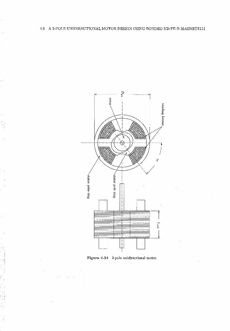
4.9 A 2-POLE UNIDIRECTIONAL MOTOR DESIGN USING BONDED ND-FE-B MAGNETS151
en en <+ <+ ~ ~ 0 0 .., .., a "d
0 @ en ::1. I='
oq
Figure 4.34 2-pole unidirectional motor.
152 CHAPTER 4 THE UNIDIRECTIONAL SINGLE PHASE SYNCHRONOUS PM MOTOR
KR is referred to as the winding resistance constant and is defined by
(4.113)
Ro is the resistance of one winding consisting of a single turn, occupying the entire
coils ide area per pole Ac. Ro is given by
(4.114)
where
Pc resistivity of copper
lo mean length per turn
Because the total length of wire is proportional to the number of turns, and the area
per turn is inversely proportional to the number of turns, the total winding resistance
is proportional to the square of the number of turns per pole, as shown by eqn. 4.112.
k--- ee
)~g \\ ~ewRe
Dyi-------?01
Figure 4.35 Estimation of the mean end winding length.
With reference to Fig. 4.35, an estimate of the mean length per turn is given by
(4.115)
The second and third RHS terms of eqn. 4.115 give contributions to the mean end
winding length. OwRe is an axial component of the end winding length due to the
thickness of the winding. Re is the mean turn radius and is given by
( Dyd2 - l f ) 2 + (Rso + l f) 2
2 (4.116)
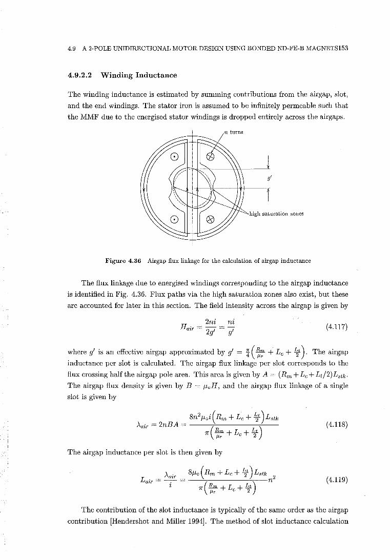
4.9 A 2-POLE UNIDIRECTIONAL MOTOR DESIGN USING BONDED ND-FE-B MAGNETS153
4.9.2.2 Winding Inductance
The winding inductance is estimated by summing contributions from the airgap, slot,
and the end windings. The stator iron is assumed to be infinitely permeable such that
the MMF due to the energised stator windings is dropped entirely across the airgaps.
n turns
high saturation zones
Figure 4.36 Airgap flux linkage for the calculation of airgap inductance
The flux linkage due to energised windings corresponding to the airgap inductance
is identified in Fig. 4.36. Flux paths via the high saturation zones also exist, but these
are accounted for later in this section. The field intensity across the airgap is given by
2ni ni Hair = 2g' = 9' (4.117)
where g' is an effective airgap approximated by g' = ~ ( ![:; + Lc + ~t ). The airgap
inductance per slot is calculated. The airgap flux linkage per slot corresponds to the
flux crossing half the airgap pole area. This area is given by A = (Rm + Lc + Lt!2)Lstk .
The airgap flux density is given by B = f-toH, and the airgap flux linkage of a single
slot is given by
(4.118)
The airgap inductance per slot is then given by
(4.119)
The contribution of the slot inductance is typically of the same order as the airgap
contribution [Hendershot and Miller 1994]. The method of slot inductance calculation
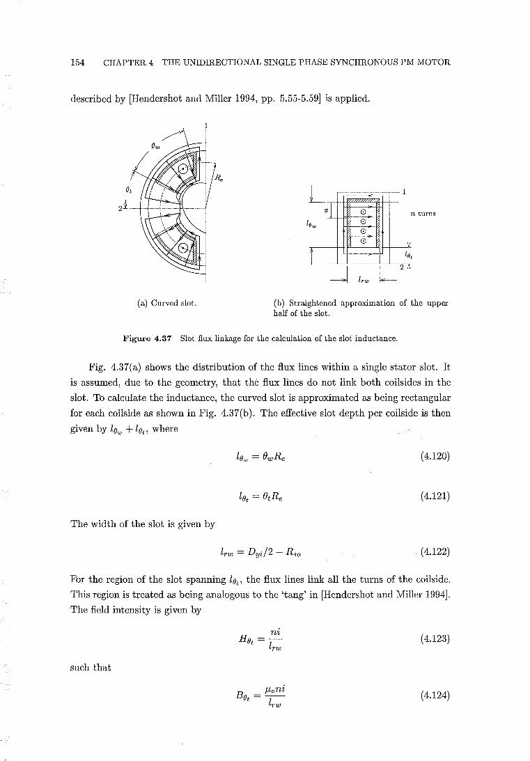
154 CHAPTER 4 THE UNIDIRECTIONAL SINGLE PHASE SYNCHRONOUS PM MOTOR
described by [Hendershot and Miller 1994, pp. 5.55-5.59] is applied.
1 I I
I
I T--
--y~ i
(a) Curved slot.
8 8
t lOt
I -----------------------------1 -J lrw L 2
(b) Straightened approximation of the upper half of the slot.
Figure 4.37 Slot flux linkage for the calculation of the slot inductance.
Fig. 4.37(a) shows the distribution of the flux lines within a single stator slot. It
is assumed, due to the geometry, that the flux lines do not link both coilsides in the
slot. To calculate the inductance, the curved slot is approximated as being rectangular
for each coilside as shown in Fig. 4.37(b). The effective slot depth per coilside is then
given by low + lOt, where
( 4.120)
(4.121)
The width of the slot is given by
(4.122)
For the region of the slot spanning lOt, the flux lines link all the turns of the coilside.
This region is treated as being analogous to the 'tang' in [Hendershot and Miller 1994].
The field intensity is given by
such that
B _ /-toni Ot - 1
rw
(4.123)
(4.124)
4.9 A 2-POLE UNIDIRECTIONAL MOTOR DESIGN USING BONDED ND-FE-B MAGNETS155
The flux linkage corresponding to this region is given by
(4.125)
and the inductance is given by
(4.126)
For the region of the slot spanning lOw' the cross-slot flux density increases as x
increases, and is given by
Bow = f-LoH = (-t-ni) (0 Ow rw
(4.127)
The incremental flux linkage is given by
(4.128)
and the flux linkage is obtained by integration:
(4.129)
and therefore
L AOw L (lOw) 2 Ow = -i- = f-Lo stk 3lrw
n (4.130)
The inductance contributions from both coilsides of the slot is then given by
(4.131)
A simple approximation of the end winding inductance is made following the
method described by [Hendershot and Miller 1994, pp. 5.59-5.60]. Each end wind
ing is treated as a half circle such that the contribution from both ends of a turn is
equivalent to that of a single circular loop. The diameter of this loop is given by
(4.132)
and the end winding inductance (per coil) is given by
f-LoDe [ 4De ] 2 Lend = -2- ln GMD - 2 n (4.133)
where GMD is the geometric mean distance between conductors in the coil cross-
156 CHAPTER 4 THE UNIDIRECTIONAL SINGLE PHASE SYNCHRONOUS PM MOTOR
section. If the coil cross-section is assumed to be square, then GMD = 0.477V Aw.
The total inductance per pole is obtained by summing the contributions from the
air gap , slot and end windings:
Lpole = eL (Lair + Lslot + Lend) (4.134)
eL is referred to as the stator flux linkage factor. It is included to account for the increase
in inductance due to the increase in flux linkage caused by the closed slot openings.
For the single pole pair motor, a value of eL = 1.2 is used. For a unidirectional motor
with an arbitrary number of pole pairs, the total inductance is given by
L = 2pLpoie (4.135)
If the number of turns per pole is not specified, the inductance is expressed by
(4.136)
where KL is the inductance constant. KL is obtained by dividing through eqn. 4.135
by n2 .
4.9.2.3 Turn Calculation
The load angle eo is a function of the number of stator winding turns. To obtain the
unidirectional load angle, at which E and I are in phase, the correct number of turns
must be specified. The correct number of turns per pole is calculated by substituting
eqn.s 4.106, 4.112, and 4.136 into eqn. 4.41, and solving for n:
n= (4.137)
The total number of stator winding turns is given by
N=2pn (4.138)
Both the single and multiple pole pair motors are designed to operate from a 220/230
V RMS, 50 Hz AC supply. In each case, the number of turns is calculated at 220 V
RMS. This ensures that each motor can operate at the lowest supply voltage.
4.9 A 2-POLE UNIDIRECTIONAL MOTOR DESIGN USING BONDED ND-FE-B MAGNETS157
4.9.3 Design Synthesis
This section lists the design, performance, and simulation parameters of the single pole
pair design. The values of the physical dimensions and angles defined in Fig. 4.34 are
listed in Table 4.4.
value units comment
Dyo 41 mm Motor diameter
Lstk 20 mm Stack length
Dr 12 mm Rotor diameter (Dr = 2Rm)
Lr 20 mm Rotor axial length
Dyi 36 mm
If 1 mm Rso 10 mm Lt 2 mm Lc 0.5 mm
'Yr 51.6 mech deg Ir is set to the value of I~
OW 48 mech deg Be 40 mech deg ot 27.5 mech deg
Table 4.4 Physical dimensions
value units comment
{} 6000 Kg/mil Density of bonded Nd-Fe-B rotor
Pc 2 X 10 ./S Om Resistivity of copper at 60° C
Br 0.66 T Remanence of bonded Nd-Fe-B at 60° C
J-lr 1.25 Relative recoil permeability of bonded Nd-Fe-B
em 0.8 PM flux linkage factor
eL 1.2 Stator flux linkage factor
sf 0.785 Stacking factor
DclDi 0.9 Ratio of uninsulated to insulated wire diameters
f 50 Hz Electrical supply frequency
V 220 VRMS Terminal voltage for turn calculation
Table 4.5 Miscellaneous input parameters
Tables 4.4 and 4.5 list all the input parameters from which all remaining parameters
are derived. Calculated parameters are listed in Table 4.6. In Table 4.6, the torque per
unit rotor volume is given by
(4.139)
The T RV provides an indication of the relative performance of the design. Comparison
with the values of Table 4.8 shows that the design is well placed for its small size and
the grade of PM used.
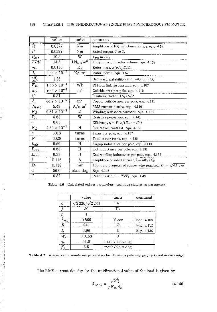
158 CHAPTER 4 THE UNIDIRECTIONAL SINGLE PHASE SYNCHRONOUS PM MOTOR
value units comment
Tr 0.0327 Nm Amplitude of PM reluctance torque, eqn. 4.52
T 0.0327 Nm Rated torque, T = Tr
Pout 10.3 W Pout = TWe
TRV 14.5 kNm/m0 Torque per unit rotor volume, eqn. 4.139
mr 0.0136 Kg Rotor mass, (1 (1f/4) D;Lr
Jr 2.44 X lOr Kg.m:l Rotor inertia, eqn. 4.67 4Wr 1.36 Backward instability ratio, with J = 2Jr Jw;
Km 1.88 X 10⁻⁴ Wb PM flux linkage constant, eqn. 4.107
Aw 70.4 X 10 -0 m:l Coilside area per pole, eqn. 4.110
if 0.81 Insulation factor, (Del Di)2
Ac 44.7 X 10 -0 m:l Copper coilside area per pole, eqn. 4.111
JRMS 5.49 A/mm:l RMS current density, eqn. 4.140
KR 9.31 X 10 -0 n Winding resistance constant, eqn. 4.113
PR 5.63 W Resistive power loss, eqn. 4.141
'Tl 0.65 Efficiency, 'T] = Pout/(Pout + PR)
KL 4.39 X lOr H Inductance constant, eqn. 4.136
n 3013 turns Turns per pole, eqn. 4.137
N 6026 turns Total stator turns, eqn. 4.138
Lair 0.69 H Airgap inductance per pole, eqn. 4.119
Lslot 0.63 H Slot inductance per pole, eqn. 4.131
Lend 0.33 H End winding inductance per pole, eqn. 4.133
i 0.116 A Amplitude of rated current, i = 4Wrl>.-;"
Dc 0.138 mm Minimum diameter of copper wire required, Dc = J4Ac/n1f a 56.0 elect deg Eqn. 4.142
r 0.82 Pullout ratio, r = TIT p, eq:il. 4.49
Table 4.6 Calculated output parameters, excluding simulation parameters.
value units comment I
{) V2 220/ V2 230 V
f 50 Hz p 1
AmI 0.566 V.sec Eqn. 4.106
R 845 n Eqn. 4.112
L 3.98 H Eqn. 4.136
Wr 0.0163 J "Ir 51.6 mech/ elect deg f3I 6.6 mech/ elect deg
Table 4.7 A selection of simulation parameters for the single pole pair unidirectional motor design.
The RMS current density for the unidirectional value of the load is given by
(4.140)
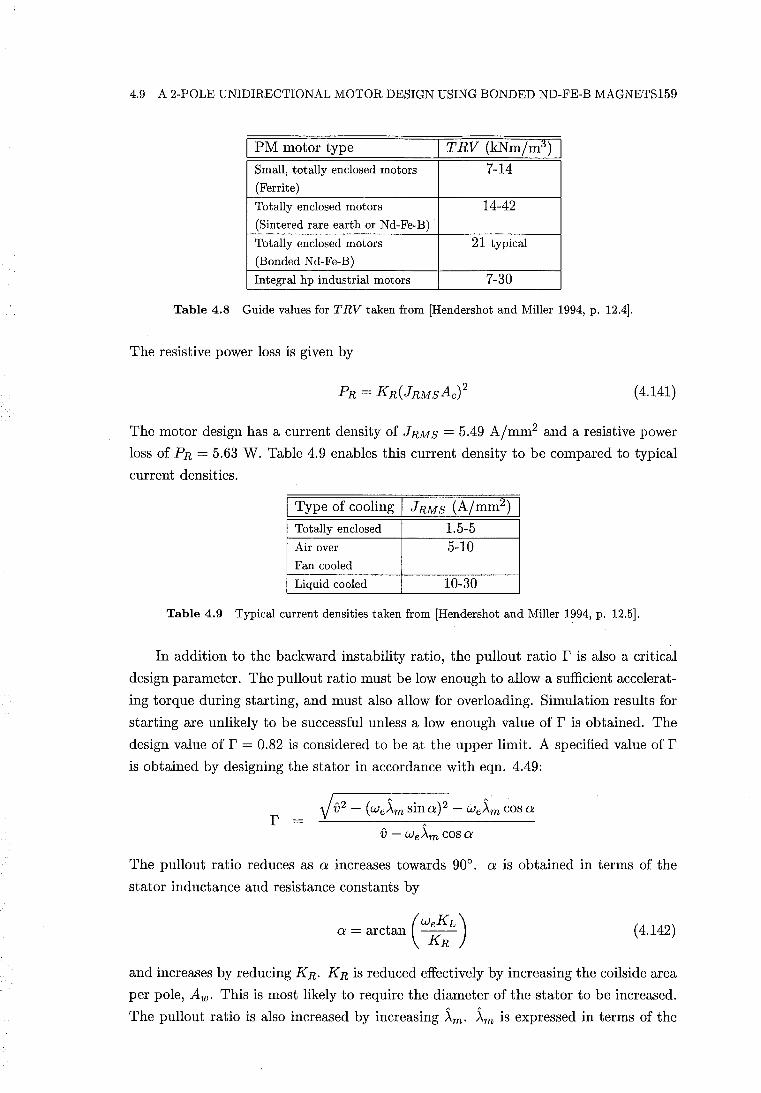
4.9 A 2-POLE UNIDIRECTIONAL MOTOR DESIGN USING BONDED ND-FE-B MAGNETS159
I PM motor type I T RV (kNm/m3) I Small, totally enclosed motors 7-14 (Ferrite)
Totally enclosed motors 14-42 (Sintered rare earth or Nd-Fe-B)
Totally enclosed motors 21 typical
(Bonded Nd-Fe-B)
Integral hp industrial motors 7-30
Table 4.8 Guide values for TRV taken from [Hendershot and Miller 1994, p. 12.4].
The resistive power loss is given by
(4.141)
The motor design has a current density of JRMS = 5.49 A/mm2 and a resistive power
loss of PR = 5.63 W. Table 4.9 enables this current density to be compared to typical
current densities.
I Type of cooling I JRMS (A/mm2) I
Totally enclosed 1.5-5 Air over 5-10 Fan cooled
Liquid cooled 10-30
Table 4.9 Typical current densities taken from [Hendershot and Miller 1994, p. 12.5].
In addition to the backward instability ratio, the pullout ratio r is also a critical
design parameter. The pullout ratio must be low enough to allow a sufficient accelerat
ing torque during starting, and must also allow for overloading. Simulation results for
starting are unlikely to be successful unless a low enough value of r is obtained. The
design value of r = 0.82 is considered to be at the upper limit. A specified value of r is obtained by designing the stator in accordance with eqn. 4.49:
r V {;2 - (we~m sina)2 - We~m cos a
{; - we~mcosa
The pullout ratio reduces as a increases towards 900• a is obtained in terms of the
stator inductance and resistance constants by
(weKL)
a = arctan KR (4.142)
and increases by reducing KR. KR is reduced effectively by increasing the coils ide area
per pole, Aw. This is most likely to require the diameter of the stator to be increased.
The pullout ratio is also increased by increasing ~m. ~m is expressed in terms of the
160 CHAPTER 4 THE UNIDIRECTIONAL SINGLE PHASE SYNCHRONOUS PM MOTOR
stator constants by
(4.143)
Eqn. 4.143 shows that decreasing KR increases the number of turns and therefore also
~m. Increasing the winding area is therefore shown to be an effective design method
for reducing r. However, there is a practical limit to the maximum motor diameter
and the amount of copper and iron that can be used. The requirement to obtain a
satisfactory value of r may result in a larger winding area and lower current density
than initially anticipated.
4.9.4 Simulation
Simulation results corresponding to the 2-pole unidirectional motor design are presented
in this section. Initial values of the state variables corresponding to starting are used.
These initial states are [i0 = 0,80 = 0,80 = I'rJ. For each simulation, it is determined
first, whether synchronisation followed by steady state motion occurs, and secondly,
whether the steady state motion is in the forward or backward direction. The motor
has not been designed for a specific application. The motor is simulated for two different
types of mechanical loads which are both functions of the rotor speed. These are purely
quadratic and purely linear loads. The linear load is modelled by
(4.144)
where Kin is the linear load coefficient.
The quadratic load is modelled using eqn. 4.56. Even with these simple models of
the load, the state equations describing the motion are a function of eleven simulation
parameters. Given the high number of parameters, and the general approach to the
application of the motor, only a limited number of parameter combinations are practical
to simulate. For the purpose of limiting the number of simulations, a hierarchy of
parameters considered to have the greatest variability is established. These parameters,
in order of increasing variability are:
1. Mechanical load type (linear or quadratic)
2. Moment of inertia, J.
3. Supply voltage (220 or 230 V RMS)
4. Load magnitude (ranging from pullout to no load)
5. Supply voltage angle at switch-on, E.
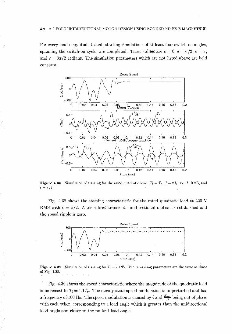
4.9 A 2-POLE UNIDIRECTIONAL MOTOR DESIGN USING BONDED ND-FE-B MAGNETS161
For every load magnitude tested, starting simulations of at least four switch-on angles,
spanning the switch-on cycle, are completed. These values are E = 0, E = 7['/2, E = 7[',
and E = 37['/2 radians. The simulation parameters which are not listed above are held
constant.
Rotor Speed
---u OJ
'" ---'1j cd ~
0 0.02 0.04 0.06 0.08 0.1 0.12 0.14 0.16 0.18 0.2 Motor Torques
0.1
S e -0.1
0 0.02 0.04 0.06 0.08 0.1 0.12 0.14 0.16 0.18 0.2 Current, EMF/torque function
~ ---S Z
~-0.5 0 0.02 0.04 0.06 0.08 0.1 0.12 0.14 0.16 0.18 0.2
time (sec)
Figure 4.38 Simulation of starting for the rated quadratic load. Tl = Tr , J = 2Jr , 220 V RMS, and E = 7r/2.
Fig. 4.38 shows the starting characteristic for the rated quadratic load at 220 V
RMS with E = 7['/2. After a brief transient, unidirectional motion is established and
the speed ripple is zero.
Rotor Speed
o 0.02 0.04 0.06 0.08 0.1 0.12 0.14 0.16 0.18 0.2 time (sec)
Figure 4.39 Simulation of starting for Tl = 1.1 Tr • The remaining parameters are the same as those of Fig. 4.38.
Fig. 4.39 shows the speed characteristic where the magnitude of the quadratic load
is increased to T" = l.lfr . The steady state speed modulation is unperturbed and has
a frequency of 100 Hz. The speed modulation is caused by i and d~1f being out of phase
with each other, corresponding to a load angle which is greater than the unidirectional
load angle and closer to the pullout load angle.
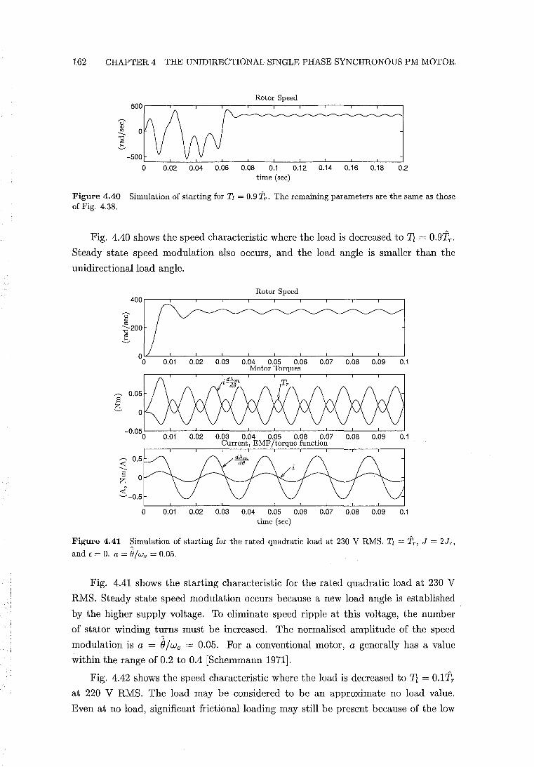
162 CHAPTER 4 THE UNIDIRECTIONAL SINGLE PHASE SYNCHRONOUS PM MOTOR
Rotor Speed
o 0.02 0.04 0.06 0.08 0.1 0.12 0.14 0.16 0.18 0.2 time (sec)
Figure 4.40 Simulation of starting for Tz = 0.9 Tr • The remaining parameters are the same as those of Fig. 4.38.
Fig. 4.40 shows the speed characteristic where the load is decreased to Il = 0.9TT •
Steady state speed modulation also occurs, and the load angle is smaller than the
unidirectional load angle.
Rotor Speed 400
U " til :a-2OO cO ~
0.01 0.02 0.03 0.04 0.05 0.06 0.07 0.08 0.09 0.1 Motor Torques
S b
0.01 0.02 0.03 0.04 0.05 0.06 0.07 0.08 0.09 0.1 Current, EMF/torque function
~ ---S 0 z ..:t;' ~-0.5
0 0.01 0.02 0.03 0.04 0.05 0.06 0.07 0.08 0.09 0.1 time (sec)
Figure 4.41 ~imulation of starting for the rated quadratic load at 230 V RMS. Tz = Tr , J = 2Jr ,
and E = O. a = B/we = 0.05.
Fig. 4.41 shows the starting characteristic for the rated quadratic load at 230 V
RMS. Steady state speed modulation occurs because a new load angle is established
by the higher supply voltage. To eliminate speed ripple at this voltage, the number
of stator winding t~rns must be increased. The normalised amplitude of the speed
modulation is a = Bjwe = 0.05. For a conventional motor, a generally has a value
within the range of 0.2 to 0.4 [Schemmann 1971].
Fig. 4.42 shows the speed characteristic where the load is decreased to Il = 0.1TT
at 220 V RMS. The load may be considered to be an approximate no load value.
Even at no load, significant frictional loading may still be present because of the low
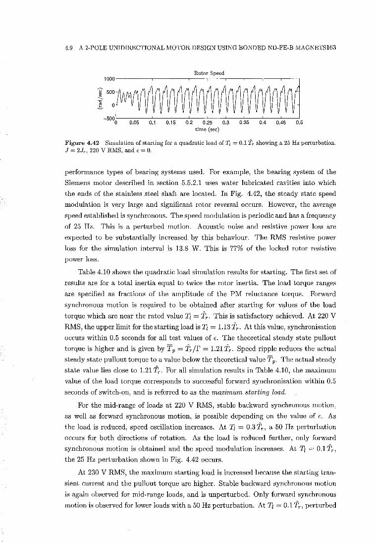
4.9 A 2-POLE UNIDIRECTIONAL MOTOR DESIGN USING BONDED ND-FE-B MAGNETS163
Rotor Speed 1000.---,----.---,----.----.---,----,----.---.----,
~ 500 tJ] --. ! _500L---~---L----L---~---L--~L---~---L--~L-~
o 0.05 0.1 0.15 0.2 0.25 0.3 0.35 0.4 0.45 0.5 time (sec)
Figure 4.42 Simulation of starting for a quadratic load of Tl = 0.1 'ir showing a 25 Hz perturbation. J = 2Jr , 220 V RMS, and E = O.
performance types of bearing systems used. For example, the bearing system of the
Siemens motor described in section 5.5.2.1 uses water lubricated cavities into which
the ends of the stainless steel shaft are located. In Fig. 4.42, the steady state speed
modulation is very large and significant rotor reversal occurs. However, the average
speed established is synchronous. The speed modulation is periodic and has a frequency
of 25 Hz. This is a perturbed motion. Acoustic noise and resistive power loss are
expected to be substantially increased by this behaviour. The RMS resistive power
loss for the simulation interval is 13.8 W. This is 77% of the locked rotor resistive
power loss.
Table 4.10 shows the quadratic load simulation results for starting. The first set of
results are for a total inertia equal to twice the rotor inertia. The load torque ranges
are specified as fractions of the amplitude of the PM reluctance torque. Forward
synchronous motion is required to be obtained after starting for values of the load
torque which are near the rated value Tz = Tr . This is satisfactory achieved. At 220 V
RMS, the upper limit for the starting load is Tz = 1.13 Tr . At this value, synchronisation
occurs within 0.5 seconds for all test values of E. The theoretical steady state pullout
torque is higher and is given by Tp = Tr/r = 1.21 Tr. Speed ripple reduces the actual
steady state pullout torque to a value below the theoretical value Tp. The actual steady
state value lies close to 1.21 Tr . For all simulation results in Table 4.10, the maximum
value of the load torque corresponds to successful forward synchronisation within 0.5
seconds of switch-on, and is referred to as the maximum starting load.
For the mid-range of loads at 220 V RMS, stable backward synchronous motion,
as well as forward synchronous motion, is possible depending on the value of E. As
the load is reduced, speed oscillation increases. At Tz = 0.3 Tr , a 50 Hz perturbation
occurs for both directions of rotation. As the load is reduced further, only forward
synchronous motion is obtained and the speed modulation increases. At Tz = 0.1 Tr ,
the 25 Hz perturbation shown in Fig. 4.42 occurs.
At 230 V RMS, the maximum starting load is increased because the starting tran
sient current and the pullout torque are higher. Stable backward synchronous motion
is again observed for mid-range loads, and is unperturbed. Only forward synchronous
motion is observed for lower loads with a 50 Hz perturbation. At Tz = 0.1 Tr , perturbed
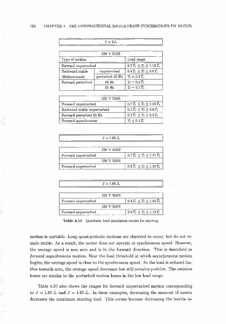
164 CHAPTER 4 THE UNIDIRECTIONAL SINGLE PHASE SYNCHRONOUS PM MOTOR
220 V RMS
Type of motion Load range
Forward unperturbed 0.7 TT ::; Tl ::; 1.13 TT Backward stable unperturbed 0.4 TT ::; Tl ::; 0.6 TT (Bidirectional) perturbed 50 Hz Tl = 0.3TT Forward perturbed 50 Hz Tl = 0.2TT
25 Hz Tl = O.lTT
230 V RMS
Forward unperturbed 0.7TT ::; Tl ::; 1.18TT Backward stable unperturbed 0.4 TT ::; Tl ::; 0.6 TT Forward perturbed 50 Hz 0.2 TT ::; Tl ::; 0.3 TT Forward asynchronous Tl ::; 0.1 TT
J = 1.85 JT
220 V RMS
Forward unperturbed I 0.7TT ::; Tl ::; 1.11 TT 230 V RMS
Forward unperturbed I 0.8 TT ::; Tl ::; 1.16 TT
J = 1.65 JT
220 V RMS
Forward unperturbed I 0.4 TT ::; Tl ::; 1.05 TT 230 V RMS
Forward unperturbed I 0.6 TT ::; Tl ::; 1.12 TT
Table 4.10 Quadratic load simulation results for starting.
motion is unstable. Long quasi-periodic motions are observed to occur, but do not re
main stable. As a result, the motor does not operate at synchronous speed. However,
the average speed is non zero and is in the forward direction. This is described as
forward asynchronous motion. Near the load threshold at which asynchronous motion
begins, the average speed is close to the synchronous speed. As the load is reduced fur
ther towards zero, the average speed decreases but still remains positive. The resistive
losses are similar to the perturbed motion losses in the low load range.
Table 4.10 also shows the ranges for forward unperturbed motion corresponding
to J = 1.85 Jr and J = 1.65 Jr' In these examples, decreasing the moment of inertia
decreases the maximum starting load. This occurs because decreasing the inertia in-
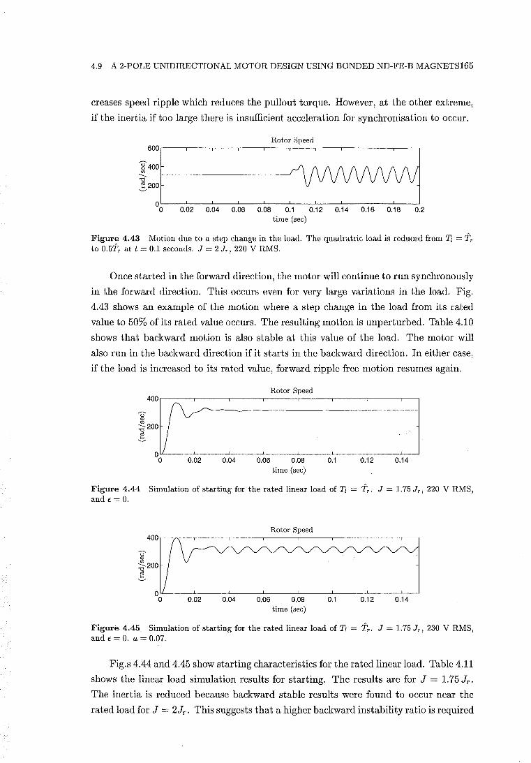
4.9 A 2-POLE UNIDIRECTIONAL MOTOR DESIGN USING BONDED ND-FE-B MAGNETS165
creases speed ripple which reduces the pullout torque. However, at the other extreme,
if the inertia if too large there is insufficient acceleration for synchronisation to occur.
Rotor Speed
I~=I : =: : ~== o 0.02 0.04 0.06 0.08 0.1 0.12 0.14 0.16 0.18 0.2 time (sec)
Figure 4.43 Motion due to a step change in the load. The quadratric load is reduced from Tl = Tr to 0.5Tr at t = 0.1 seconds. J = 2 Jr , 220 V RMS.
Once started in the forward direction, the motor will continue to run synchronously
in the forward direction. This occurs even for very large variations in the load. Fig.
4.43 shows an example of the motion where a step change in the load from its rated
value to 50% of its rated value occurs. The resulting motion is unperturbed. Table 4.10
shows that backward motion is also stable at this value of the load. The motor will
also run in the backward direction if it starts in the backward direction. In either case,
if the load is increased to its rated value, forward ripple free motion resumes again.
Rotor Speed
I:::~ : : :: :: I o 0.02 0.04 0.06 0.08 0.1 0.12 0.14
time (sec)
Figure 4.44 Simulation of starting for the rated linear load of Tl = Tr . J = 1.75 Jr , 220 V RMS, and E = O.
Rotor Speed
I::: o 0.02 0.04 0.06 0.08 0.1 0.12 0.14
time (sec)
Figure 4.45 Simulation of starting for the rated linear load of Tl = Tr • J = 1.75 Jr , 230 V RMS, and E = O. a = 0.07.
Fig.s 4.44 and 4.45 show starting characteristics for the rated linear load. Table 4.11
shows the linear load simulation results for starting. The results are for J = 1. 75 Jr'
The inertia is reduced because backward stable results were found to occur near the
rated load for J = 2Jr . This suggests that a higher backward instability ratio is required
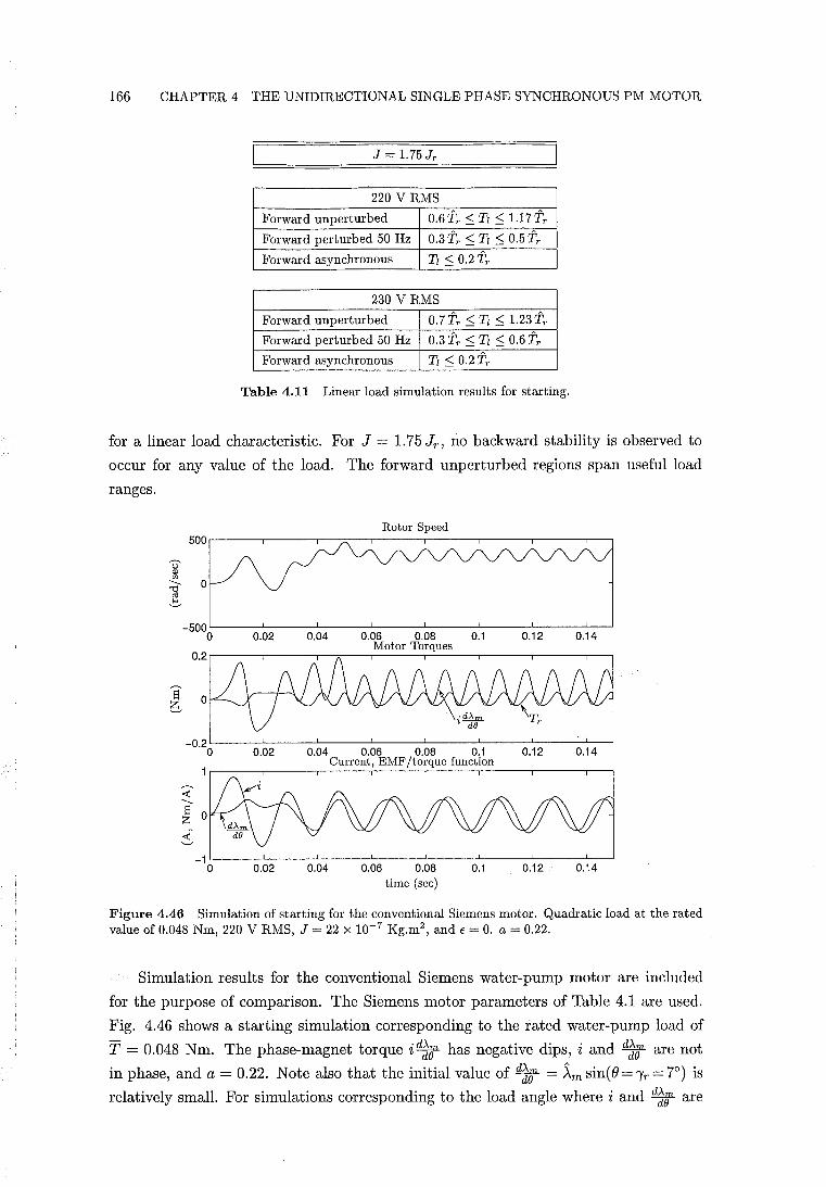
166 CHAPTER 4 THE UNIDIRECTIONAL SINGLE PHASE SYNCHRONOUS PM MOTOR
J = 1.75 JT
220 V RMS
Forward unperturbed 0.61\ ::; Tl ::; 1.17TT
Forward perturbed 50 Hz 0.3TT ::; Tl ::; 0.5TT
Forward asynchronous Tl < 0.2TT
230 V RMS
Forward unperturbed 0.7TT < Tl ::; 1.23TT
Forward perturbed 50 Hz 0.3 TT ::; Tl ::; 0.6 TT
Forward asynchronous Tl < 0.2TT
Table 4.11 Linear load simulation results for starting.
for a linear load characteristic. For J = 1.75 Jr , no backward stability is observed to
occur for any value of the load. The forward unperturbed regions span useful load
ranges.
Rotor Speed 500.-----.------.--~--.------.-----,,-----.------.--.
_500L-----~----~------L------L----~------~-----L~
o 0.02 0.04 0.06 0.08 0.1 0.12 0.14 Motor Torques
0.2,_----.-----.--.---,-----,~----._----._----_,__.
-0.2 L-____ -'--____ --'-______ ~ ____ ___L ____ ___.JL_ ____ _'_ ____ ___L_
0.14 o 0.02 0.04 0.06 0.08 0.1 Current, EMF/torque function
0.12
_1L------'--------'-------~-------L-------.JL------'--------L-o 0.02 0.04 0.06 0.08 0.1 0.12 0.14
time (sec)
Figure 4.46 Simulation of starting for the conventional Siemens motor. Quadratic load at the rated value of 0.048 Nm, 220 V RMS, J = 22 X 10-7 Kg.m2 , and E = O. a = 0.22.
Simulation results for the conventional Siemens water-pump motor are included
for the purpose of comparison. The Siemens motor parameters of Table 4.1 are used.
Fig. 4.46 shows a starting simulation corresponding to the rated water-pump load of
T = 0.048 Nm. The phase-magnet torque id2lf has negative dips, i and d23' are not
in phase, and a = 0.22. Note also that the initial value of d23' = ~msin(e=')'r=7°) is
relatively small. For simulations corresponding to the load angle where i and d23' are
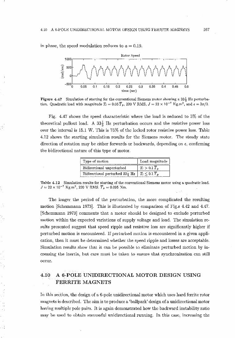
4.10 A 6-POLE UNIDIRECTIONAL MOTOR DESIGN USING FERRITE MAGNETS 167
in phase, the speed modulation reduces to a = 0.19.
Rotor Speed 1000.---~---.----.----.----~---r---''---~--~----'
_500L----L--~----~--~----L----L--~~--~--~--~
o 0.05 0.1 0.15 0.2 0.25 0.3 0.35 0.4 0.45 0.5 time (sec)
Figure 4.47 Simulation of starting for the conventional Siemens motor showing a 33~ Hz perturbation. Quadratic load with magnitude Tl = 0.05 Tp, 220 V RMS, J = 22 X 10-7 Kg.m2
, and € = 31[,/2.
Fig. 4.47 shows the speed characteristic where the load is reduced to 5% of the
theoretical pullout load. A 33* Hz perturbation occurs and the resistive power loss
over the interval is 15.1 W. This is 75% of the locked rotor resistive power loss. Table
4.12 shows the starting simulation results for the Siemens motor. The steady state
direction of rotation may be either forwards or backwards, depending on E, confirming
the bidirectional nature of this type of motor.
I Type of motion Load magnitude
Bidirectional unperturbed Tl > O.lTp
Bidirectional perturbed 33~ Hz Tl::; O.lTp
Table 4.12 Simulation results for starting of the conventional Siemens motor using a quadratic load. J = 22 X 10-7 Kg.m2
, 220 V RMS. Tp = 0.095 Nm.
The longer the period of the perturbation, the more complicated the resulting
motion [Schemmann 1973]. This is illustrated by comparison of Fig.s 4.42 and 4.47.
[Schemmann 1973] comments that a motor should be designed to exclude perturbed
motion within the expected variations of supply voltage and load. The simulation re
sults presented suggest that speed ripple and resistive loss are significantly higher if
perturbed motion is encountered. If perturbed motion is encountered in a given appli
cation, then it must be determined whether the speed ripple and losses are acceptable.
Simulation results show that it can be possible to eliminate perturbed motion by in
creasing the inertia, but care must be taken to ensure that synchronisation can still
occur.
4.10 A 6-POLE UNIDIRECTIONAL MOTOR DESIGN USING FERRITE MAGNETS
In this section, the design of a 6-pole unidirectional motor which uses hard ferrite rotor
magnets is described. The aim is to produce a 'ballpark' design of a unidirectional motor
having multiple pole pairs. It is again demonstrated how the backward instability ratio
may be used to obtain successful unidirectional running. In this case, increasing the
168 CHAPTER 4 THE UNIDIRECTIONAL SINGLE PHASE SYNCHRONOUS PM MOTOR
pole pair number allows lower performance PM material to be used with a rotor of
a larger diameter. This is explained with reference to eqn. 4.103, where increasing
P compensates for the reduction in the ratio Wr / J caused by using lower remanence
magnets and a larger rotor diameter. The rotor diameter is 19 mm, and is the same as
that of the conventional Siemens 2-pole ferrite motor.
The design is analogous, in most respects, to the unidirectional single pole pair
design. Parallel magnetised rotor poles, closed stator slots, and most of the previously
introduced design equations, are again applied. The final design is the result of a
number of iterations and its success is evaluated by simulation.
4.10.1 Rotor and Airgap Design
The design of the rotor and airgap involves calculation of the PM reluctance torque,
the backward instability ratio, and the EMF/torque function per turn.
4.10.1.1 PM Reluctance Torque
The air gap dimensions are listed in Table 4.13. The rotor overhangs the stator lamina
tion stack by 2.5 mm at each end. The PM material characteristics are listed in Table
4.14. A linear recoil permeability is assumed and the remanence is the same as that
of the conventional Siemens motor. The PM reluctance torque is calculated using the
model developed in section 4.8. Fig. 4.48 plots the stored energy and the reluctance
torque. The frequency spectrum of Tr shows that a small second harmonic is present,
and that higher order harmonics are negligible. Wr and Tr are therefore approximated
by their fundamental values.
4.10.1.2 The EMF/Torque function
Fig. 4.49 plots the EMF/torque function per turn. The frequency spectrum of dt;; shows that the third harmonic component is significant. The fundamental component
d~(Jl is phase shifted by angle /31 due to the airgap modulation.
In an analogous manner to the single pole pair design, it is shown for a multiple pole
pair design that with P 'Yr = 7r / 4 electrical radians, the corresponding phase shift of the
fundamental component of the EMF/torque function d~7r exacerbates speed ripple.
Simulation results show that speed ripple is minimised for the multiple pole pair motor
if Tr and d~t are aligned according to eqn. 4.104, such that P'Yr - /31 = ~. The /31 versus 'Yr characteristic for the multiple pole pair motor is nearly identical to that of the
single pole pair characteristic shown in Fig. 4.33. Therefore, a nearly exact solution for
the alignment of Tr and d~rt is given by eqn. 4.105, such that P'Y; = ~ + /31 (P'Yr = ~). In Fig. 4.49, d1; is plotted for this value of 'Yr.
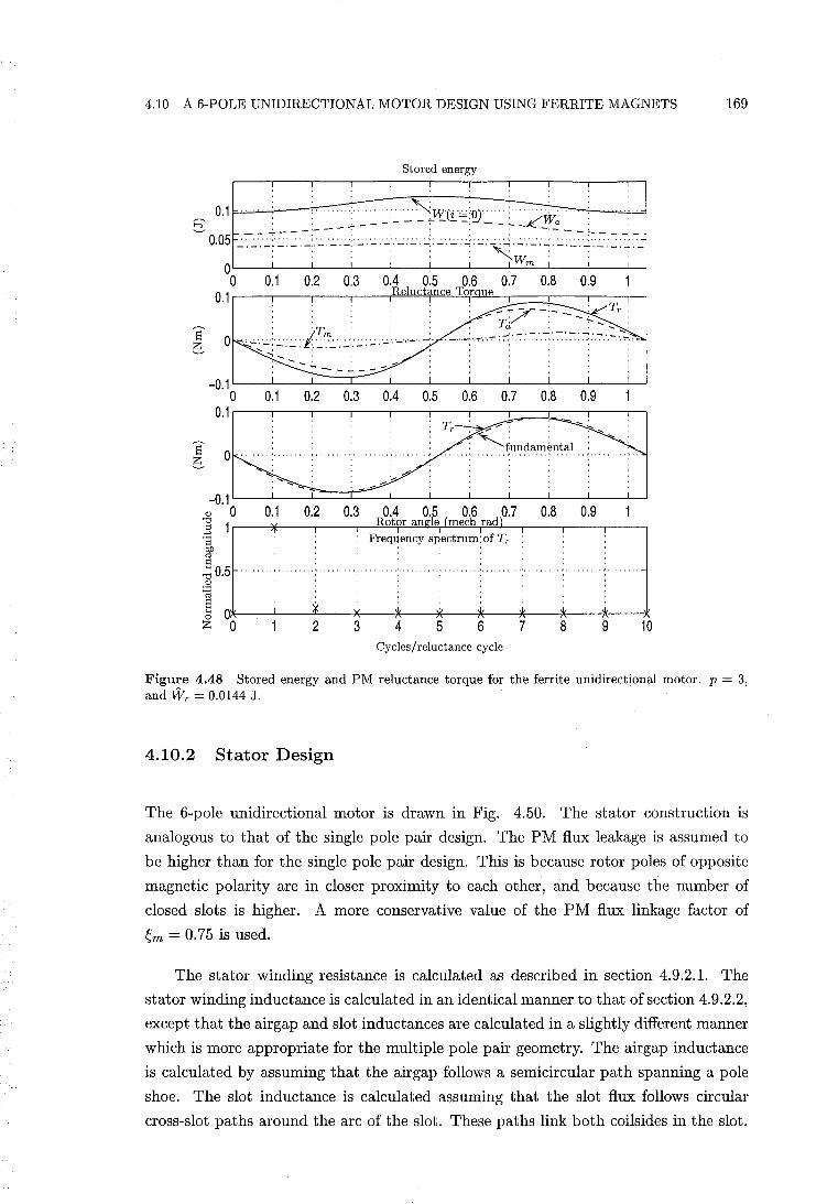
4.10 A 6-POLE UNIDIRECTIONAL MOTOR DESIGN USING FERRITE MAGNETS 169
Stored energy
o 0.1 0.2 0.3 0.4 0.5 0.6 0.7 0.8 0.9 1 0.1 Reluctance Tor ue
.~
-..;. - --,
- ~7-:- : Tr : .... Tci : - - ~,,_ : - -::-::.-::.-:.,-:-:".:-::-:::-:::.7:.7"·~1
-0.1 L----L_-L==:r::::::::~_--L_...L-----1_--L_---L-_LJ o 0.1 0.2 0.3 0.4 0.5 0.6 0.7 0.8 0.9
0.11---r--,---,---,---,-.,----::!:::====+:=---:--~ Tr ~
: ~fundamental ! 0
-0.1 L----L_....I:::::::Jc:::=..---L_--L------1_---L_--L-----1_--L.J
Q) 0 0.1 0.2 0.3 0.4 0.5 0.6 0.7 0.8 0.9 ] 1r-__ ~---.----,-~R~o~to~r~a~n~~11eT~(lm~e~c~hTra~d~r_,--_,----._--, .t; Frequency spectrum: of Tr : ~ S
"0 0.5 Q)
~ ~ Ol*-__ -L __ ~¥~ __ *~·--~w~--~---~w·----*---~~~--~--~ ZO 2345678 9 10
Cycles/reluctance cycle
Figure 4.48 Stored energy and PM reluctance torque for the ferrite unidirectional motor. p = 3, and Wr = 0.0144 J.
4.10.2 Stator Design
The 6-pole unidirectional motor is drawn in Fig. 4.50. The stator construction is
analogous to that of the single pole pair design. The PM flux leakage is assumed to
be higher than for the single pole pair design. This is because rotor poles of opposite
magnetic polarity are in closer proximity to each other, and because the number of
closed slots is higher. A more conservative value of the PM flux linkage factor of
~m = 0.75 is used.
The stator winding resistance is calculated as described in section 4.9.2.1. The
stator winding inductance is calculated in an identical manner to that of section 4.9.2.2,
except that the airgap and slot inductances are calculated in a slightly different manner
which is more appropriate for the multiple pole pair geometry. The airgap inductance
is calculated by assuming that the air gap follows a semicircular path spanning a pole
shoe. The slot inductance is calculated assuming that the slot flux follows circular
cross-slot paths around the arc of the slot. These paths link both coils ides in the slot.
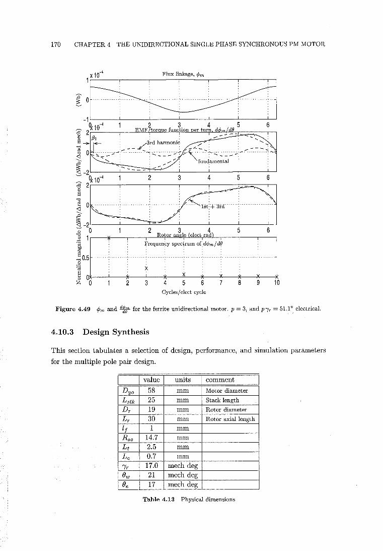
170 CHAPTER 4 THE UNIDIRECTIONAL SINGLE PHASE SYNCHRONOUS PM MOTOR
Frequency spectrum ofd</Jm/d{)
X
Ol*----L--~~--L---~,;~,--~~'----,~,',--~~~--*'"'--~W~' ---* 023 4 5 6 7 8 9 10
Cycles / elect cycle
Figure 4.49 ¢m and ~ for the ferrite unidirectional motor. p = 3, and p "{r = 51.10 electrical.
4.10.3 Design Synthesis
This section tabulates a selection of design, performance, and simulation parameters
for the multiple pole pair design.
I value I units comment
Dyo 58 mm Motor diameter
Lstk 25 mm Stack length
Dr 19 mm Rotor diameter
Lr 30 mm Rotor axial length
If 1 mm
Rso 14.7 mm Lt 2.5 mm Lc 0.7 mm
Ir 17.0 mech deg
Ow 21 mech deg
Oe 17 mech deg
Table 4.13 Physical dimensions
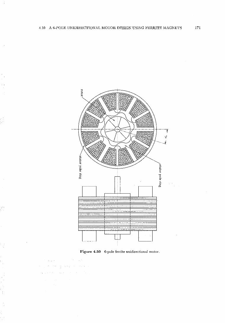
4.10 A 6-POLE UNIDIRECTIONAL MOTOR DESIGN USING FERRITE MAGNETS 171
s· ()q
I I I I I
I I
I
I I w Figure 4.50 6-pole ferrite unidirectional motor.
172 CHAPTER 4 THE UNIDIRECTIONAL SINGLE PHASE SYNCHRONOUS PM MOTOR
value units comment
e 4900 Kg/mil Density of ferrite rotor
Br 0.42 T Remanence of ferrite rotor
{tr 1.07 Relative recoil permeability of ferrite
em 0.75 PM flux linkage factor
eL 1.33 Stator flux linkage factor
DclDi 0.9 Ratio of uninsulated to insulated wire diameters
V 220 VRMS Terminal voltage for turn calculation
Table 4.14 Miscellaneous input parameters
value units comment
Tr 0.0864 Nm Amplitude of PM reluctance torque, eqn. 4.52
T 0.0864 Nm Rated torque, T = Tr
RPM 1000 Revolutions per minute
Pout 9.05 W Pout = Twe/p
TRV 12.2 kNm/mil Torque per unit rotor volume, eqn. 4.139
mr 0.0417 Kg Rotor mass, 1l(7r/4)D;Lr
Jr 18.8 X 10 7 Kg.m~ Rotor inertia, eqn. 4.67 4Wrp2 1.40 Backward instability ratio, with J = 2Jr Jw2
Aw 78.7 X 10⁻¹) m~ Coilside area per pole, eqn. 4.110
Km 2.71 X 10⁻⁴ Wb PM flux linkage constant, eqn. 4.107
KR 21.9 X 10 -b n Winding resistance constant, eqn. 4.113
KL 7.29 X 10 7 H Inductance constant, eqn. 4.136
JRMS 3.00 A/mm'L RMS current density, eqn. 4.140
PR 4.97 W Resistive power loss, eqn. 4.141
'f} 0.65 Efficiency, 1] = Pout/(Pout + PR )
n 2216 turns Turns per pole, eqn. 4.137
N 13296 turns Total stator turns, eqn. 4.138
~ 0.096 A Amplitude of rated current, i = 4Wr/)':"
Dc 0.170 mm Minimum diameter of copper wire required, Dc = J4Ac/n7r
r 0.825 Pullout ratio, r = T /Tp , eqn. 4.49
Table 4.15 Calculated output parameters, excluding simulation parameters.
In Table 4.15, the torque per unit rotor volume is good, but the output power is
lowered because the higher number of pole pairs reduces the mechanical speed to one
third of the electrical speed. The values of backward instability ratio, resistive power
loss, and pullout ratio r are all similar to those of the single pole pair design. The
current density is not high. However, the coilside area per pole and stator diameter
cannot be reduced. This is because doing so increases r, as explained in section 4.9.3,
and r is already at its upper limit in this design.
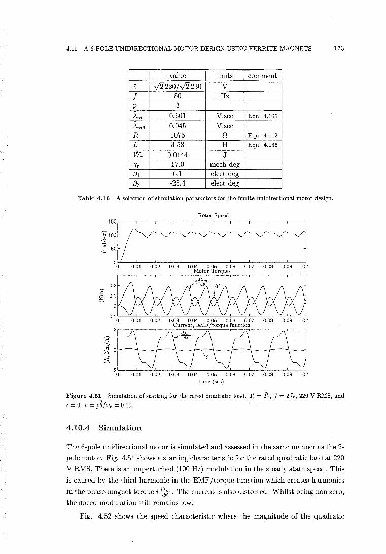
4.10 A 6-POLE UNIDIRECTIONAL MOTOR DESIGN USING FERRITE MAGNETS 173
value units comment I v V2 220/ V2 230 V
f 50 Hz p 3
AmI 0.601 V.sec Eqn. 4.106
Am3 0.045 V.sec R 1075 n Eqn. 4.112
L 3.58 H Eqn. 4.136
WT 0.0144 J
"iT 17.0 mech deg (31 6.1 elect deg (33 -25.4 elect deg
Table 4.16 A selection of simulation parameters for the ferrite unidirectional motor design.
~100 en
---"d ! 50
S 6 0.1
Rotor Speed
0.01 0.02 0.03 0.04 0.05 0.06 0.07 0.08 0.09 0.1 Motor Torques
-0.1 '------=:::..--'-----OO-.J._-==---'-----=::---L_-"'---'------.:::.--'-----'::..-.J'-----=----'-----O'----L~_==___.l o 0.01 0.02 0.03 0.04 0.05 0.06 0.07 0.08 0.09 0.1
Current, EMF !torque function 2 tJ 'd~'[j '[j '[j j !lSL~q
o 0.01 0.02 0.03 0.04 0.05 0.06 0.07 0.08 0.09 0.1 time (sec)
Figure 4.5~ Simulation of starting for the rated quadratic load. Tz = Tr , J = 2Jr , 220 V RMS, and
E = O. a = piJ/we = 0.09.
4.10.4 Simulation
The 6-pole unidirectional motor is simulated and assessed in the same manner as the 2-
pole motor. Fig. 4.51 shows a starting characteristic for the rated quadratic load at 220
V RMS. There is an unperturbed (100 Hz) modulation in the steady state speed. This
is caused by the third harmonic in the EMF/torque function which creates harmonics
in the phase-magnet torque i d~B' The current is also distorted. Whilst being non zero,
the speed modulation still remains low.
Fig. 4.52 shows the speed characteristic where the magnitude of the quadratic
174 CHAPTER 4 THE UNIDIRECTIONAL SINGLE PHASE SYNCHRONOUS PM MOTOR
Rotor Speed 150.------.-----.------,------r-----.------.------.--.
time (sec)
Figure 4.52 Simulation of starting for Tl = 1.1 Tr . The remaining parameters are the same as those of Fig. 4.51. a = 0.07.
load is increased to Tz = 1.1fr . The speed ripple is decreased slightly at this value of
the load. Fig. 4.53 shows that the speed modulation is larger for a reduced load of
Tz = a.9fr .
Rotor Speed 150
~100 tI.l
---"'g ~
0 0 0.02 0.04 0.06 0.08 0.1 0.12 0.14
time (sec)
Figure 4.53 Simulation of starting for Tl = 0.9 Tr • The remaining parameters are the same as those of Fig. 4.51. a = 0.14.
J = 2Jr
220 V RMS
Type of motion Load range
Forward unperturbed 0.75Tr S Tl S 1.15Tr
Backward stable unperturbed 0.5Tr S Tl S 0.7Tr
(Bidirectional) perturbed 50 Hz TI=OATr
Forward perturbed 50 Hz O.lTr < Tl < 0.3Tr
25 Hz Tl = 0.05Tr
230 V RMS
Forward unperturbed O.S Tr < Tl < 1.24Tr
Backward stable unperturbed 0.6Tr S Tl < 0.75Tr
Forward unperturbed Tl = 0.5Tr
Backward stable perturbed 50 Hz Tl = OATr
Forward perturbed 50 Hz O.lTr S Tl S 0.3Tr
Forward asynchronous Tl < 0.05Tr
Table 4.17 Quadratic load simulation results for starting.
Table 4.17 shows the quadratic load simulation results for starting. Forward unper
turbed motion is obtained over a satisfactory range of the starting load. Perturbations
4.11 CONCLUSIONS 175
and backward stability can occur at lower load values. The results are similar to those
of the 2-pole unidirectional motor.
Rotor Speed
time (sec)
Figure 4.54 Simulation of starting for the rated linear load. J = 1.75 JT , 220 V RMS, and E = O. a = 0.11.
Fig. 4.54 shows a starting characteristic for the rated linear load. Table 4.18 shows
J = 1.75 JT
220 V RMS
Forward unperturbed 0.7TT ~ Tz ~ 1.14TT
Forward perturbed 50 Hz 0.2TT ~ Tz ~ 0.6TT
Forward asynchronous Tz ~ O.lTT
230 V RMS
Forward unperturbed 0.6 TT ~ Tz ~ 1.21TT
Forward perturbed 50 Hz 0.2TT ~ Tz ~ 0.5TT
Forward asynchronous Tz ~ O.lTT
Table 4.18 Linear load simulation results for starting.
the linear load simulation results for starting. The inertia is reduced to J = 1.75 Jr
because backward stable results were found to occur near the rated load for J = 2 Jr.
This again suggests that a higher backward instability ratio is required for a linear
load. The linear load results are very similar to those of the 2-pole motor.
In summary, the self-correcting ability and motion of this multiple pole pair motor
are quite similar to that of the single pole pair motor. However, a small amount of
speed ripple is unavoidable for a multiple pole pair motor at the rated load because of
the presence of the third harmonic in the EMF jtorque function.
4.11 CONCLUSIONS
The concept of the unidirectional single phase PM motor has been developed. It is
shown that the theory of the conventional single phase synchronous PM motor pro
vides a general framework for the unidirectional motor. Within this framework, the
unidirectional motor is designed to operate at a specific load angle where the current
176 CHAPTER 4 THE UNIDIRECTIONAL SINGLE PHASE SYNCHRONOUS PM MOTOR
and the EMF ftorque function are in phase. Steady state equations specific to this
unidirectional load angle have been developed.
The backward instability ratio is proposed as an approximate measure of the ability
of a unidirectional motor to self correct its direction of rotation. Two unidirectional
motor designs which use this ratio as a design guide are completed. The first motor
design uses a single pole pair (p = 1) and a higher grade of PM material, which is
bonded Nd-Fe-B. The second design uses multiple pole pairs (p = 3) and ferrite grade
magnets.
These designs use parallel magnetised rotor poles and closed stator slots. This
allows the unidirectional motor concept to be implemented in a manufacturable con
struction. It is shown that the common single stator slot design cannot be used because
a sufficiently large PM reluctance torque displacement angle "ir cannot be obtained.
Theoretical models are developed for calculating the EMF ftorque function and the
PM reluctance torque of these designs. It is shown that a single pole pair parallel mag
netised rotor yields a sinusoidal EMF ftorque function. In the unidirectional design,
phase shifting of the EMF ftorque function occurs due to the sinusoidal airgap modu
lation. It is shown that as the number of pole pairs increases, a parallel magnetisation
more closely approximates a radial magnetisation. This results in the third harmonic
in the EMF ftorque function becoming significant for pole pair numbers greater than
one. The PM reluctance torque is obtained by calculating the stored field energy in
the rotor and airgap. The model developed shows that parallel magnetised rotor poles
and a sinusoidal airgap modulation yield a very good approximation of a sinusoidal
reluctance torque.
Each motor is simulated using the equations of motion to evaluate design success.
Mechanical loads which are either linear or quadratic functions of the rotor speed are
used in the simulations. The 2-pole motor is shown to exhibit unidirectional behaviour
over a satisfactory range of starting loads. Unidirectional motion without speed ripple
is achieved at the rated load and rated terminal voltage. Simulation results show that
this design is particularly well suited to quadratic loads such as water-pumps. The
construction of the 2-pole motor is simple. However, production of this motor may
be presently excluded because of the higher cost of bonded Nd-Fe-B magnet material
in comparison to ferrite material. The use of bonded Nd-Fe-B yields a relatively high
value of torque per unit rotor volume (T RV) in comparison to the conventional 2-pole
ferrite motor designs.
The 6-pole ferrite motor is also shown to exhibit unidirectional behaviour over
a satisfactory range of starting loads. However, it is shown that the third harmonic
present in the EMF ftorque function exacerbates speed ripple. The speed ripple at
the rated load still remains relatively small compared to the conventional designs. This
multiple pole pair motor is less attractive than the single pole pair motor in a number of
4.11 CONCLUSIONS 177
other respects. The cost of the ferrite material is acceptable but the cost and complexity
of the construction is higher. A higher number of rotor poles are required. Each rotor
pole is required to be individually magnetised prior to the assembly of the rotor. The
stator construction is similarly more complex. The punching of stator laminations is
more intricate. More windings and winding connections are required. A higher number
of turns are required to be wound. Both the 2-pole and 6-pole designs deliver a similar
amount of power even though the 6-pole motor is considerably larger. The 6-pole motor
requires over three times as much copper as the 2-pole design. More stator iron is also
required to accommodate the larger winding area. The output power is lowered because
the higher number of poles reduces the mechanical speed to one third of the electrical
speed. The reduction in the power density caused by the reduction in the rotor speed
is identified as a major drawback of a multiple pole pair design in general. The 6-pole
design uses the same rotor dimensions and ferrite material as the conventional 2-pole
Siemens water-pump motor. The rated torque of the 6-pole motor is much higher than
that of the Siemens motor. But to achieve the same power density (per unit rotor
volume) as the Siemens motor, the rated torque of the 6-pole motor must be increased
by 66%. This is not possible because the amplitude of the PM reluctance torque cannot
be made larger without making the modulation of the rotor airgap excessively large.
The stator would also become oversized.
Because the advantage of a high power density is lost, it would appear that a
multiple pole pair motor is only of advantage if a slower synchronous shaft speed is
required. The 6-pole motor is designed to run at a synchronous speed of 1000 RPM.
This is a suitable speed for running a fan if the acoustic noise is required to be limited.
The load of a fan is also a quadratic function of the rotor speed. The unidirectional
nature of the motor ensures that air is not blown backwards after starting. However,
being able to satisfactorily reduce the inertia of the fan blades to within the maximum
allowable limit whilst still attaining the required airflow may prove to be challenging
in such an application.
The unidirectional motor design, in general, offers solutions or improvements to
several of the less desirable characteristics of the conventional 2-pole design. As men
tioned in section 1.2.6, the twice electrical frequency speed oscillations of the conven
tional motor produce noise. This noise hampers the use of these motors in high quality
household appliances [Altenbernd and Wahner 1996]. In contrast, the unidirectional
motor is proposed to greatly reduce, or eliminate altogether, speed ripple about the
rated value of the load.
The final direction of rotation is not predetermined for the conventional motor.
This limits the application of the conventional motor to water-pumps and reciprocating
loads if a mechanical device is not used to correct the direction of rotation. For the
unidirectional motor, such a device may be omitted.

178 CHAPTER 4 THE UNIDIRECTIONAL SINGLE PHASE SYNCHRONOUS PM MOTOR
As mentioned in section 1.2.2, the magnitude of the PM reluctance torque available
to move the rotor to a startable position is low because the PM reluctance torque
displacement angle 'Yr is limited. This places a restriction on the magnitude of any
speed independent component of the load. For example, if the rotor is de-accelerating
to rest after de-energisation, and the load torque is greater than the reluctance torque,
then the rotor may come to rest at e = O. In this case, the motor cannot restart. The
PM reluctance torque of the unidirectional motor is equal to the rated torque at this
rotor position. Therefore, in contrast, the unidirectional motor is capable of rotating
the rotor to a startable position even if the speed independent load is nearly as large as
the rated torque. This raises the possibility of using the unidirectional motor in load
applications which the conventional motor cannot start.
The concept of the unidirectional motor has now been developed in detail. The
theory and ideas presented now require experimental validation. This will identify any
considerations which may have been overlooked, and will lead to further understanding
and refinement of the ideas presented.
4.11.1 2-Pole Unidirectional Motor Designs using Ferrite Rotors
This section describes two proposed unidirectional motor designs which are considered
to be more practical for production. In each design, the rotor is constructed using a
2-pole ferrite rotor. The rotor design is therefore cheap and simple. The 2-pole closed
slot design of Fig. 4.34 is used.
The first design is described as follows. The proportionality relationship in eqn.
4.103 suggests that if the rotor diameter is made small enough, then a single pole pair
rotor of ferrite construction will have a sufficiently high backward instability ratio.
Analysis of the rotor and airgap design suggests that a rotor diameter of about 10 mm
is at the upper limit for a 2-pole ferrite rotor design. The corresponding amplitude of
the PM reluctance torque obtained corresponds to a rated output power of about 3.5 to
4 Watts. This rating is in the range of the motors originally described by [Thees 1965].
The conventional motors in this power range are limited to applications such as elec
tric can openers, juicers, and aquarium pumps [Altenbernd and Wahner 1996]. The
conventional single phase synchronous PM motor manufactured by Hozelock3 is an ex
ample of a garden waterpump in this power range. A mechanical direction correcting
device is employed to make the impeller rotation unidirectional. This device consists
of a plastic arm which is pushed out by the waterflow into the impeller chamber to
impede rotation only if the direction of rotation is incorrect. The proposed advantage
of the unidirectional ferrite motor in such an application is that the correcting device
is not required, and the pump is expected to run more quietly and smoothly.
3Nameplate details are: Hozelock Micro 450 model 3304-0000, 230 V, 50 Hz, 6 W (power input), 0.03 A. Maximum head height 1 metre, 450 litres/hr. Made in the UK.
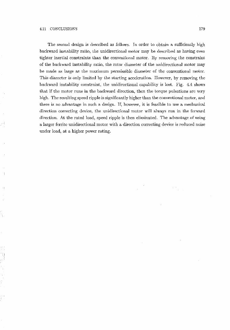
4.11 CONCLUSIONS 179
The second design is described as follows. In order to obtain a sufficiently high
backward instability ratio, the unidirectional motor may be described as having even
tighter inertial constraints than the conventional motor. By removing the constraint
of the backward instability ratio, the rotor diameter of the unidirectional motor may
be made as large as the maximum permissible diameter of the conventional motor.
This diameter is only limited by the starting acceleration. However, by removing the
backward instability constraint, the unidirectional capability is lost. Fig. 4.4 shows
that if the motor runs in the backward direction, then the torque pulsations are very
high. The resulting speed ripple is significantly higher than the conventional motor, and
there is no advantage in such a design. If, however, it is feasible to use a mechanical
direction correcting device, the unidirectional motor will always run in the forward
direction. At the rated load, speed ripple is then eliminated. The advantage of using
a larger ferrite unidirectional motor with a direction correcting device is reduced noise
under load, at a higher power rating.

Chapter 5
THE INDUCTIVE START SINGLE PHASE SYNCHRONOUS PM MOTOR
5.1 INTRODUCTION
Conventional single phase synchronous PM motor designs rely upon modifying the PM
reluctance torque to achieve a non-zero displacement angle to allow starting. This is
achieved by using either an asymmetric stator airgap or a saturating notch design,
as described in section 1.2.2. Eqn. 2.64 shows that there are three torque producing
mechanisms available in PM machines. The middle term of this equation identifies
an inductive reluctance torque which is present when a winding is energised and the
inductance of the winding is changing as a function of rotor position. This inductive
reluctance torque is not exploited in the conventional designs. This chapter investigates
the use of the inductive reluctance torque to enable a single phase PM motor to start.
5.2 THEORETICAL BASIS
Fig. 5.1(a) illustrates the PM reluctance torque concept developed in Chapters 1 and 4
where the PM displacement angle IT' is set to 45 electrical degrees. This allows the PM
reluctance torque available to move the rotor to a startable position to be maximised
about the () = 0 position. Fig. 5.1(b) shows a waveform of the same phase and period,
dW(i=O) --d-O- 0
'Yr
(a) Uni-directional.
dL dOo 80
'Yl
(b) Inductive start.
Figure 5.1 Mechanisms for the provision of torque about rotor alignment angle e = 0 for single phase synchronous PM motor designs.
182 CHAPTER 5 THE INDUCTIVE START SINGLE PHASE SYNCHRONOUS PM MOTOR
corresponding to the derivative of inductance with respect to rotor position. This is a
hypothetical inductance characteristic. In eqn. 2.64, for the magnetically linear case,
the inductive reluctance torque in the PM motor is given byl
(5.1)
Therefore, with the stator winding energised, the inductance characteristic of Fig.
5.1(b) also provides a torque to move the rotor to a startable position away from the
e = 0 position. Furthermore, during switch-on, the current corresponds to the locked
rotor current providing a significant boost to the inductive reluctance torque.
The aim of this chapter is not to design a motor with the characteristic of Fig.
5.1(b) implemented in order to attempt to achieve unidirectional motion, but to fa
cilitate the starting of the motor only. As such, the motor will be referred to as the
inductive start motor. The direction of final rotation still remains un-predetermined
like the conventional motor.
5.2.1 Inductance
The inductance of the conventional motor varies as a function of both the rotor position
and the stator winding current, such that L = L(i, e). However, the modulation ofthe
inductance is small compared to its DC value. By assuming the inductance to be
constant, a model of the motor is simplified. The conventional motor is modelled
sufficiently accurately by making this simplifying assumption.
For the inductive start motor, the assumption of constant inductance does not allow
a reluctance torque model to be developed. For the inductive start motor, analysis of
inductance modulation during start up must be included. The inductance can be
calculated from
(5.2)
where the permeance P is given by
(5.3)
lThe inductive reluctance torque is assumed to have this form. The total motor torque is given exactly by eqn. 2.62, but the reluctance components of torque are not clearly resolved. In eqn. 2.64, an attempt is made to resolve these components. However, eqn. 2.64 relies upon the simplifying assumption of separating the stored energy W(i, (}) into mutually exclusive components provided by the winding and magnet as given by eqn. 2.63. Eqn. 2.63, is however, an approximation. It is questionable whether W(i, (}) can be resolved exactly into two mutually exclusive components, which represent energies associated with the two reluctance torques. Thus it is questionable whether exact further resolution of eqn. 2.62 is possible. Thus, it is possible that neither the second nor third RHS terms of eqn. 2.64 are exact. However, eqn. 2.64 has been shown to model the motion of a single phase PM motor sufficiently accurately. In this current chapter, eqn. 5.1 is conveniently extracted from eqn. 2.64 for the purpose of developing a model.
5.2 THEORETICAL BASIS 183
In eqn. 5.3, the relative permeability /-lr can be defined by an effective value repre
senting the entire magnetic circuit of the stator. Similarly, flux path cross-sectional
area A, and flux path length l can be defined as effective quantities which represent
the physical dimensions of the magnetic circuit. The ratio All is fixed if the physical
dimensions of the magnetic circuit do not change. The modulation of the inductance
of the conventional motor may therefore be described as being caused only by a mod
ulation of /-lr, as motion of the rotor does not change the physical dimensions of the
magnetic circuit. The modulation of /-lr is caused by modulation of the resultant MMF.
The relationship between the resultant MMF and /-lr is nonlinear, and is dependent on
the magnetisation characteristic of the stator iron used. If hysteresis is present, /-lr is a
function of the magnetisation history as well as the resultant MMF.
The resultant MMF is the vector sum of MMF contributions from the energised
stator winding, and the PM rotor. This is illustrated by Fig. 4.1, where the stator MMF
is proportional to the stator current I, and the rotor MMF is proportional to fictitious
current 1m. For the case where synchronous motion occurs at constant instantaneous
speed with constant load, the amplitude of the stator current remains fixed. In this
case the resultant MMF is fixed in amplitude, and varies sinusoidally as a function of
both time and rotor angle.
The relative permeability not a function of the sign of the resultant MMF, but
only of its absolute value. The relative permeability and permeance therefore complete
two cycles of modulation per cycle of resultant MMF. The result is an inductance
modulation which completes two cycles per electrical cycle. Fig. 4.1 shows that the
phase and amplitude of the resultant MMF changes with load angle. The modulation
of the inductance is therefore also affected by the load angle.
For the case where the rotor is stationary and locked at an arbitrary rotor position,
the rotor MMF is represented by 1m remaining fixed with respect to time. With respect
to the rotor, the stator current oscillates. The magnitude of the stator current over an
electrical cycle may by represented by its RMS value. This RMS value is permanently
aligned with the stator d-axis. This is illustrated by Fig. 5.2. Fig. 5.2 shows that the
resultant locked rotor MMF does, however, vary sinusoidally as a function of the rotor
position. This results in both the locked rotor permeance and inductance completing
two cycles of modulation per mechanical cycle for a 2-pole motor.
The locked rotor inductance measurements of Fig. 5.22 show that the locked ro
tor inductance characteristic completes two cycles per electrical cycle. The inductance
characteristics are quasi-sinusoidal. As a first approximation, the locked rotor induc
tance may then be described mathematically by
(5.4)
for a 2-pole motor where
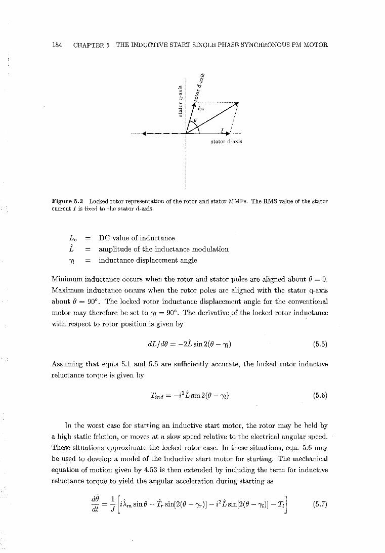
184 CHAPTER 5 THE INDUCTIVE START SINGLE PHASE SYNCHRONOUS PM MOTOR
........ ~- .. --.-.-.~~...I..-----.,;:~
stator d-axis
Figure 5.2 Locked rotor representation ofthe rotor and stator MMFs. The RMS value of the stator current I is fixed to the stator d-axis.
L o DC value of inductance
L amplitude of the inductance modulation
"Il inductance displacement angle
Minimum inductance occurs when the rotor and stator poles are aligned about e = o. Maximum inductance occurs when the rotor poles are aligned with the stator q-axis
about e = 90°. The locked rotor inductance displacement angle for the conventional
motor may therefore be set to "Il = 90°. The derivative of the locked rotor inductance
with respect to rotor position is given by
dL/de = -2Lsin2(e - "Il) (5.5)
Assuming that eqn.s 5.1 and 5.5 are sufficiently accurate, the locked rotor inductive
reluctance torque is given by
(5.6)
In the worst case for starting an inductive start motor, the rotor may be held by
a high static friction, or moves at a slow speed relative to the electrical angular speed.
These situations approximate the locked rotor case. In these situations, eqn. 5.6 may
be used to develop a model of the inductive start motor for starting. The mechanical
equation of motion given by 4.53 is then extended by including the term for inductive
reluctance torque to yield the angular acceleration during starting as
5.2 THEORETICAL BASIS 185
5.2.2 The Start Angle
As mentioned previously, for the conventional motor, the purpose of the non-zero PM
displacement angle 'Yr is to bring the rotor into a position where the phase-magnet
torque i~m sin 0 can proceed to bring the rotor into synchronism. The purpose of
using an inductive reluctance torque is similar. Thus in an inductive start motor,
the conventional method used to create a non-zero PM displacement angle 'Yr can be
eliminated. With an asymmetric stator airgap or saturating technique removed, 'Yr
becomes zero. However, the PM reluctance torque still remains .. For example, if the
techniques for creating a non-zero 'Yr are removed from the designs of Fig. 1.2, cogging
torques will act to align the rotor and stator direct axes2 . Thus, for the inductive start
motor, the rest angle when the stator is de-energised is 0 = 'Yr = 0, and the rotor and
stator poles are aligned.
The PM reluctance, as well as the phase-magnet and inductive reluctance torques
may all be present near the rotor and stator alignment angle when the stator winding is
energised. Because the purpose of the inductive reluctance torque is to bring the rotor
to a startable position where the phase-magnet torque i~m sinO can act significantly,
the influence of the phase-magnet torque in this process will be ignored. With 'Yr = 0,
the PM reluctance torque opposes any rotation which dis aligns the rotor and stator
direct axes. The presence of the PM reluctance torque prevents the inductive reluctance
torque from moving the rotor to the inductive torque rest position at 0 = 'Yl. Instead,
the rotor will come to rest at an equilibrium angle which will be called the start angle
'Yst, if the influence of the phase-magnet torque is ignored. The start angle 'Yst is
defined for the purpose of quantitatively assessing the starting ability of an inductive
start motor.
If the PM and inductive reluctance torques are assumed to be sinusoidal quantities
then the start angle may be calculated using eqn. 5.7. The torques corresponding to
the terms i~m sin 0 and Tz are ignored. If the rotor is moving at a slow speed relative
to the electrical angular speed, the inductive reluctance torque pulsates at twice the
electrical frequency. Because the inductive torque is proportional to the square of the
current, it can be represented by an average value corresponding to the RMS value of
the locked rotor current Ilkr. Under this representation, the PM and inductive torques
balance each other at static equilibrium when 0 = 'Yst. The angular acceleration is zero.
In this case, with 'Yr = 0, eqn. 5.7 reduces to
(5.8)
The start angle may be obtained from eqn. 5.8.
2The q-axis notches in Fig 1.2(b) in this case remain, preventing PM flux from short-circuiting the windings. The d-axis notches are filled in.
186 CHAPTER 5 THE INDUCTIVE START SINGLE PHASE SYNCHRONOUS PM MOTOR
Note that the start angle is not the angle at which acceleration to synchronisation
finally occurs. Synchronisation is discussed in section 1.2.3.
5.2.2.1 Experimental Measurement of the Start Angle
The start angle may be measured experimentally by coupling a sufficiently large mo
ment of inertia to the rotor shaft. This method is explained with reference to eqn. 5.7.
With a sufficiently large J the phase-magnet torque i~m sinO is able to generate only
a very small angular acceleration over either a positive or negative half cycle of the
locked rotor current. This acceleration is reversed over the subsequent half cycle. This
results in the effective averaging of the phase-magnet torque to zero. It is impossible
for synchronisation to occur. However, the PM and inductive reluctance torques do
not average to zero. The angular acceleration provided by these two torques eventually
rotates the rotor to the equilibrium position '"'1st. The value of the additional moment
of inertia is chosen such that electrical frequency oscillation of the shaft is visually
imperceptible.
5.2.3 Modifying the Inductance
As described in section 5.2.1, the locked rotor inductance of the conventional motor
varies as a function of rotor position. However, substitution of '"'Il = 90° into eqn. 5.6
shows that the inductive reluctance torque is zero at 0 = O. To achieve a desirable
inductance characteristic to allow starting, an appropriate additional inductance char
acteristic La must be superimposed upon the conventional characteristic Le. Eqn. 5.4
may then be expressed as the sum of two components:
L = Lo + L cos 2(0 - '"'Il) = Le + La (5.9)
Given the first approximation of a sinusoidal characteristic, the conventional inductance
may be described by
(5.10)
where '"'Ile = 90°. By assuming a sinusoidal characteristic, the additional locked rotor
inductance may be described by
La = Loa + La cos 2(0 - '"'Ila) (5.11)
where Loa is the DC value contributed by the additional inductance The additional
inductance may be physically realised by attaching a specially designed iron lamination
to the rotor. The theory and design of an iron rotor lamination is described in section
5.2.4. Eqn.s 5.10 and 5.11 may be substituted into eqn. 5.9. Differentiation with
5.2 THEORETICAL BASIS 187
respect to rotor position followed by substitution into eqn. 5.1 then yields eqn. 5.6
resolved into two components of inductive reluctance torque:
(5.12)
Substitution of eqn. 5.12 into eqn. 5.8 with () = 'Yst and i = Ilkr yields the torque
balance between the PM reluctance torque and the two inductive torque components:
(5.13)
To be feasible, an inductive start motor should have a start angle 'Yst as least as large
as the PM reluctance torque displacement angle 'Yr of a comparable conventional motor.
For an inductive start motor design where 'Yst has been specified, the required amplitude
of the additional inductance La will be obtained from eqn. 5.13. Assuming that the
Siemens motor can be modified to become an inductive start motor, a calculation of the
required value of La is of initial interest. Values of relevant parameters corresponding
to the conventional Siemens motor are listed in Table 5.1.
I value I units I comments
'Yr 7 elect deg Measured
Tr 0.03 Nm Approximate value
Loe 1.528 H Average measured locked rotor value over
an inductance cycle at 220 V RMS
Le 0.108 H Measured locked rotor value at 220 VRMS
Ilkr 0.445 A (RMS) Average measured locked rotor value over
an inductance cycle at 220 V RMS
'Yle 90 elect deg
Table 5.1 Conventional Siemens motor parameters. The method of inductance measurement is described in section 5.5.5.1 and the inductance measurements correspond to Fig. 5.22.
Setting 'Yla = 45° produces a dLa/d() characteristic equivalent to Fig. 5.1(b).
This ideally provides for maximum inductive reluctance torque at () = 0°. For the
conventional Siemens motor, 'Yr = 7°. The value of La calculated for 'Yst = 7° is 0.0096
H. This amplitude represents 0.6% of the average inductance Loe. This calculation
suggests that only a small La is required. Fig. 5.3 plots the inductances used in this
example.
The DC value of additional inductance Loa, may however, be considerably larger
than La. For the purpose of illustration, a value of Loa = 8La is used in Fig. 5.3. Fig.
5.4 plots the corresponding derivatives of inductances with respect to rotor position.
Fig. 5.5 plots the conventional inductive reluctance torque which is identified by
Tinde , the additional inductive reluctance torque which is identified by Tinda, the PM
reluctance torque Tr , and the resultant of all three of these torques. The resultant
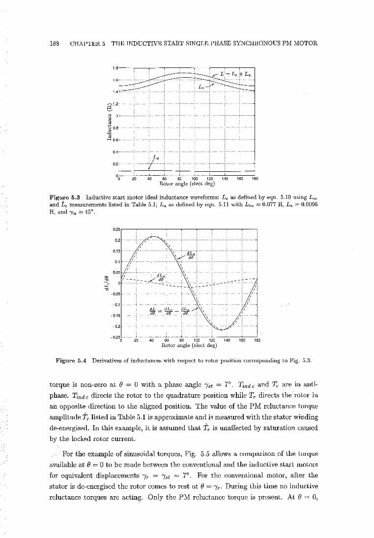
188 CHAPTER 5 THE INDUCTIVE START SINGLE PHASE SYNCHRONOUS PM MOTOR
20 40 60 60 100 120 140 160 180 Rotor angle (elect deg)
Figure 5.3 Inductive start motor ideal inductance waveforms: Lc as defined by eqn. 5.10 using Lac and tc measurements listed in Table 5.1; La as defined by eqn. 5.11 with Loa = 0.077 H, La = 0.0096 H, and ria = 450
•
20 40 60 80 100 120 140 160 180 Rotor angle (elect deg)
Figure 5.4 Derivatives of inductances with respect to rotor position corresponding to Fig. 5.3.
torque is non-zero at e = 0 with a phase angle 1st = 7°. Tind c and Tr are in anti
phase. Tind c directs the rotor to the quadrature position while Tr directs the rotor in
an opposite direction to the aligned position. The value of the PM reluctance torque
amplitude'ir listed in Table 5.1 is approximate and is measured with the stator winding
de-energised. In this example, it is assumed that 'ir is unaffected by saturation caused
by the locked rotor current.
For the example of sinusoidal torques, Fig. 5.5 allows a comparison of the torque
available at e = 0 to be made between the conventional and the inductive start motors
for equivalent displacements Ir = 1st = 7°. For the conventional motor, after the
stator is de-energised the rotor comes to rest at e = Ir' During this time no inductive
reluctance torques are acting. Only the PM reluctance torque is present. At e = 0,
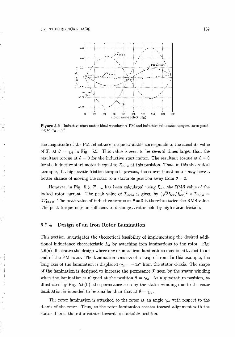
5.2 THEORETICAL BASIS
0.03 ··········· .. 1·;:;,.··-'~·~· . " y ~
.. y.-:-~~.:-.. ~4.~~~~~ ....... (. i/o : '\~ . ';' ~ . "./" ........... : .......... \.,. :// :', : ;\
0.02 .
; ,. i r~sultarit \ S 0.01/~ ......... "...:.\~ ....... / ...... ..;.....;.\ ..
I: : : : \ .' : e. 1 • zTinda : \ .' o \ -:-:-::::':'''--~'-'~':'':::.2.~\:.\:2 -' - - - -'-:--:;1
: / ,: /' ............. , ........ " ., .. 1: ........ t~ ". . )f .. .
/" 'f
\: "'tst .~
-0.02 ......... "'. :\
'.
./: " /< ,. .; . ... / .... ;.. "" .. , .. ~ ..... ,...: ..:...~.;-.t:
:.1 : ;'" : /: Tt -0.03 ................... ', .. -.«:.
o 20 40 60 80 100 120 140 160 180 Rotor angle (elect de g)
189
Figure 5.5 Inductive start motor ideal waveforms: PM and inductive reluctance torques corresponding to "Yst = 7°.
the magnitude of the PM reluctance torque available corresponds to the absolute value
of Tr at () = I'st in Fig. 5.5. This value is seen to be several times larger than the
resultant torque at () = 0 for the inductive start motor. The resultant torque at () = 0
for the inductive start motor is equal to Tind a at this position. Thus, in this theoretical
example, if a high static friction torque is present, the conventional motor may have a
better chance of moving the rotor to a startable position away from () = o. However, in Fig. 5.5, Tinda has been calculated using Ilkr, the RMS value of the
locked rotor current. The peak value of Tinda is given by (...;'2Ilkr/Ilkr)2 X Tinda =
2 Tind a' The peak value of inductive torque at () = 0 is therefore twice the RMS value.
The peak torque may be sufficient to dislodge a rotor held by high static friction.
5.2.4 Design of an Iron Rotor Lamination
This section investigates the theoretical feasibility of implementing the desired addi
tional inductance characteristic La by attaching iron laminations to the rotor. Fig.
5.6(a) illustrates the design where one or more iron laminations may be attached to an
end of the PM rotor. The lamination consists of a strip of iron. In this example, the
long axis of the lamination is displaced I'la = -450 from the stator d-axis. The shape
of the lamination is designed to increase the permeance P seen by the stator winding
when the lamination is aligned at the position () = I'la. At a quadrature position, as
illustrated by Fig. 5.6(b), the permeance seen by the stator winding due to the rotor
lamination is intended to be smaller than that at () = I'la.
The rotor lamination is attached to the rotor at an angle I'la with respect to the
d-axis of the rotor. Thus, as the rotor lamination rotates toward alignment with the
stator d-axis, the rotor rotates towards a startable position.
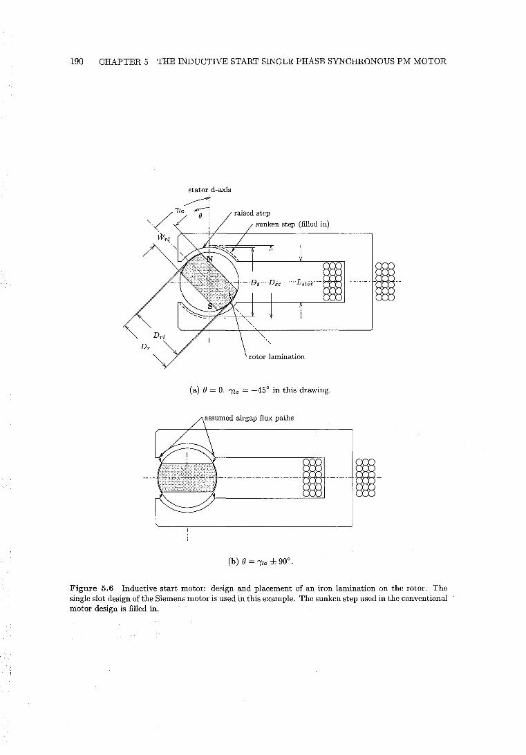
190 CHAPTER 5 THE INDUCTIVE START SINGLE PHASE SYNCHRONOUS PM MOTOR
stator d-axis
~ 'Yla ~
/ O!
'-, I raised step
sunken step (filled in)
W"{ "
rotor lamination
(a) () = O. 'Yla = -450 in this drawing.
(b) () = 'Yla ± 900,
Figure 5.6 Inductive start motor: design and placement of an iron lamination on the rotor. The single slot design of the Siemens motor is used in this example. The sunken step used in the conventional motor design is filled in,
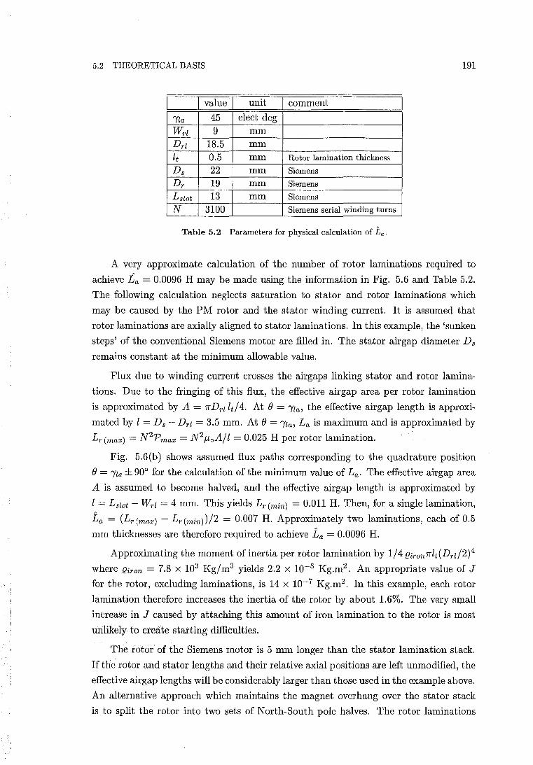
5.2 THEORETICAL BASIS 191
I value I unit I comment
ria 45 elect deg
Wrl 9 mm
Drl 18.5 mm
it 0.5 mm Rotor lamination thickness
Ds 22 mm Siemens
Dr 19 mm Siemens
Lslot 13 mm Siemens
N 3100 Siemens serial winding turns
Table 5.2 Parameters for physical calculation of La.
A very approximate calculation of the number of rotor laminations required to
achieve La = 0.0096 H may be made using the information in Fig. 5.6 and Table 5.2.
The following calculation neglects saturation to stator and rotor laminations which
may be caused by the PM rotor and the stator winding current. It is assumed that
rotor laminations are axially aligned to stator laminations. In this example, the 'sunken
steps' of the conventional Siemens motor are filled in. The stator airgap diameter Ds
remains constant at the minimum allowable value.
Flux due to winding current crosses the airgaps linking stator and rotor lamina
tions. Due to the fringing of this flux, the effective airgap area per rotor lamination
is approximated by A = nDrl lt!4. At () = ria, the effective airgap length is approxi
mated by l = Ds - Drl = 3.5 mm. At () = ria, La is maximum and is approximated by
Lr (max) = N 2p max = N 2 f-toA/l = 0.025 H per rotor lamination.
Fig. 5.6{b) shows assumed flux paths corresponding to the quadrature position
() = ria ± 900 for the calculation of the minimum value of La. The effective airgap area
A is assumed to become halved, and the effective airgap length is approximated by
l = Lslot - Wrl = 4 mm. This yields Lr (min) = 0.011 H. Then, for a single lamination,
La = (Lr(max) - L r (min))/2 = 0.007 H. Approximately two laminations, each of 0.5
mm thicknesses are therefore required to achieve La = 0.0096 H.
Approximating the moment of inertia per rotor lamination by 1/4 {}iron7rlt{Drl/2)4
where {}iron = 7.8 X 10³ Kg/m3 yields 2.2 x 10⁻⁸ Kg.m2 . An appropriate value of J
for the rotor, excluding laminations, is 14 x 10-7 Kg.m2 . In this example, each rotor
lamination therefore increases the inertia of the rotor by about 1.6%. The very small
increase in J caused by attaching this amount of iron lamination to the rotor is most
unlikely to create starting difficulties.
The rotor of the Siemens motor is 5 mm longer than the stator lamination stack.
If the rotor and stator lengths and their relative axial positions are left unmodified, the
effective airgap lengths will be considerably larger than those used in the example above.
An alternative approach which maintains the magnet overhang over the stator stack
is to split the rotor into two sets of North-South pole halves. The rotor laminations
192 CHAPTER 5 THE INDUCTIVE START SINGLE PHASE SYNCHRONOUS PM MOTOR
are placed in between the two halves. The rotor laminations are then located at the
centre of the lamination stack after assembly. However, this approach increases the
complexity of rotor construction and requires pole alignment of the two sets of magnet
poles.
5.3 THEORETICAL COMPARISON
Sections 5.3.1 and 5.3.2 provide a theoretical comparison of the inductive start and
conventional motors.
5.3.1 Starting
The PM reluctance torque provided by the conventional motor at () = 0 is obtained
from eqn. 1.8 as
(5.14)
The magnitude of this torque must be sufficient to overcome friction to bring the rotor
to rest at a startable position. Substitution of 'Yla = 45°, () = 0, and i = .j2Ilkr into
the second RHS term of eqn. 5.12 yields the corresponding peak inductive reluctance
torque provided by the inductive start motor upon energisation:
(5.15)
For the conventional motor, 'Yr is typically limited as discussed in section 1.2.2. The
PM reluctance torque at () = 0 is therefore not easily increased. However, the inductive
motor torque at () = 0 may be increased by adding more rotor laminations to increase
La. Similarly, by adding more rotor laminations, the start angle may also be increased.
5.3.2 Synchronous Motion
The inductive start motor design enables the conventional stator asymmetric step,
or the saturating notch technique, to be eliminated. Elimination of the asymmetric
step enables the average air gap clearance between rotor and stator to be reduced.
This increases the PM flux linkage per turn CPm and the peak flux linkage ~m' With
reference to the single slot design of Fig. 5.6(a), the increase in ~m is a function ofthe
sunken step's width. The increase in ~m is also a function of the sunken step depth,
(Dsc - Ds)/2, relative to the airgap clearance (Ds - Dr)/2.
Modelling constant inductance for steady state synchronous motion allows the
conventional equations for motor performance to be applied to the inductive start
5.4 AN EXPERIMENTAL DESIGN 193
motor. This enables comparative calculations of torque and efficiency to be made
using eqn.s 4.11 and 4.17, respectively. The pullout torque may be given by
(5.16)
Increasing the PM flux ¢m by reducing the average air gap increases ~m, as ~m = N ¢m' If ~m was previously set at a desirable magnitude, then increasing ¢m will require the
number of turns N to be reduced to re-establish this magnitude. The impedance
is reduced if the number of turns can be reduced. This does not change CY, as the
resistance and inductance are both proportional to the square of the turn number. But
decreasing the impedance increases the pullout torque. However, adding laminations to
the rotor increases the inductance by a value of Loa, and may increase PM flux leakage
at the rotor ends. This increases the impedance and decreases ¢m. But increasing
the inductance also increases CY, which increases the pullout torque. It is therefore
difficult to determine if the pullout torque increases in an inductive start design by this
theoretical comparison.
The theoretical model and design developed in the preceding sections suggest the
following. First, only a small La is required to achieve a useful start angle. Secondly,
a simple physical implementation is achievable. This suggests that the inductive start
motor may be technically feasible. The theoretical analysis presented provides motiva
tion to now proceed to an experimental investigation of the inductive start motor.
5.4 AN EXPERIMENTAL DESIGN
A conventional Siemens motor is modified to become an inductive start motor. This
permits a useful comparison of both motor designs.
5.4.1 Rotor Lamination Design
Preliminary experiments were first carried out to determine an effective rotor lamina
tion shape. The shapes of Fig. 5.7 were stamped out of silicon steel sheet. The rotor
and its housing were removed from the Siemens stator lamination stack. Each of the
rotor lamination shapes was centred, in turn, inside the stator airgap supported by a
small shaft. The stator winding was energised at 220 V RMS and the torque exerted
on each rotor lamination was felt via finger pressure. The shape in Fig. 5.7(b) pro
duced the largest aligning torque. Various widths (corresponding to dimension Wrl in
Fig. 5.6(a)) of this shape were then tested. Fig. 5.7(b) shows the dimensions of the
finalised rotor lamination design. The dimension Wrl = 9 mm was considered by this
experimental process to be approximately optimal for reluctance torque production
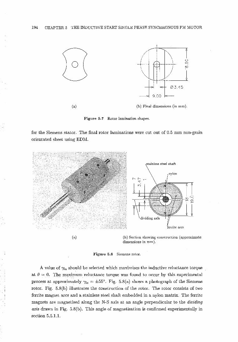
194 CHAPTER 5 THE INDUCTIVE START SINGLE PHASE SYNCHRONOUS PM MOTOR
(a)
o LO
CXJ
(b) Final dimensions (in mm).
Figure 5.7 Rotor lamination shapes.
for the Siemens stator. The final rotor laminations were cut out of 0.5 mm non-grain
orientated sheet using EDM.
ferrite arcs
(a) (b) Section showing construction (approximate dimensions in mm).
Figure 5.8 Siemens rotor.
A value of 'Yla should be selected which maximises the inductive reluctance torque
at () = O. The maximum reluctance torque was found to occur by this experimental
process at approximately 'Yla = ±55°. Fig. 5.8{ a) shows a photograph of the Siemens
rotor. Fig. 5.8{b) illustrates the construction of the rotor. The rotor consists of two
ferrite magnet arcs and a stainless steel shaft embedded in a nylon matrix. The ferrite
magnets are magnetised along the N-S axis at an angle perpendicular to the dividing
axis drawn in Fig. 5.8{b). This angle of magnetisation is confirmed experimentally in
section 5.5.1.1.
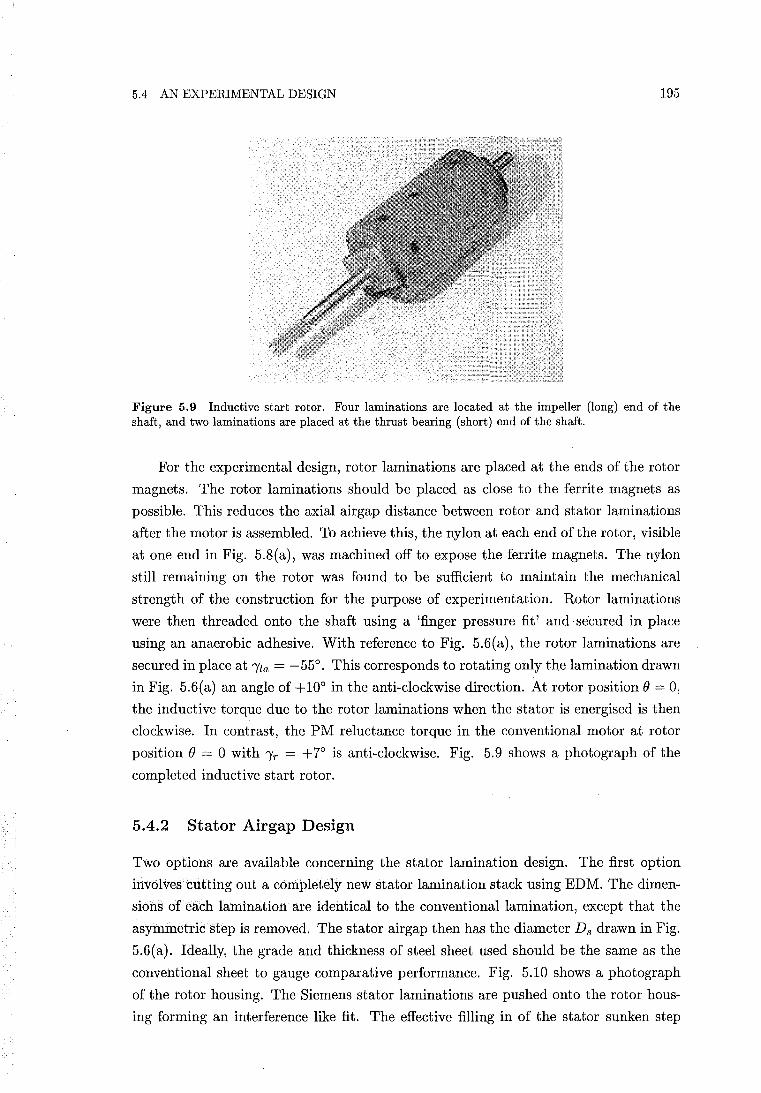
5.4 AN EXPERIMENTAL DESIGN 195
Figure 5.9 Inductive start rotor. Four laminations are located at the impeller (long) end of the shaft, and two laminations are placed at the thrust bearing (short) end of the shaft.
For the experimental design, rotor laminations are placed at the ends of the rotor
magnets. The rotor laminations should be placed as close to the ferrite magnets as
possible. This reduces the axial airgap distance between rotor and stator laminations
after the motor is assembled. To achieve this, the nylon at each end ofthe rotor, visible
at one end in Fig. 5.8(a), was machined off to expose the ferrite magnets. The nylon
still remaining on the rotor was found to be sufficient to maintain the mechanical
strength of the construction for the purpose of experimentation. Rotor laminations
were then threaded onto the shaft using a 'finger pressure fit' and secured in place
using an anaerobic adhesive. With reference to Fig. 5.6(a), the rotor laminations are
secured in place at Ila = -55°. This corresponds to rotating only the lamination drawn
in Fig. 5.6(a) an angle of +10° in the anti-clockwise direction. At rotor position () = 0,
the inductive torque due to the rotor laminations when the stator is energised is then
clockwise. In contrast, the PM reluctance torque in the conventional motor at rotor
position () = 0 with Ir = +7° is anti-clockwise. Fig. 5.9 shows a photograph of the
completed inductive start rotor.
5.4.2 Stator Airgap Design
Two options are available concerning the stator lamination design. The first option
involves cutting out a completely new stator lamination stack using EDM. The dimen
sions of each lamination are identical to the conventional lamination, except that the
asymmetric step is removed. The stator airgap then has the diameter D s drawn in Fig.
5.6(a). Ideally, the grade and thickness of steel sheet used should be the same as the
conventional sheet to gauge comparative performance. Fig. 5.10 shows a photograph
of the rotor housing. The Siemens stator laminations are pushed onto the rotor hous
ing forming an interference like fit. The effective filling in of the stator sunken step
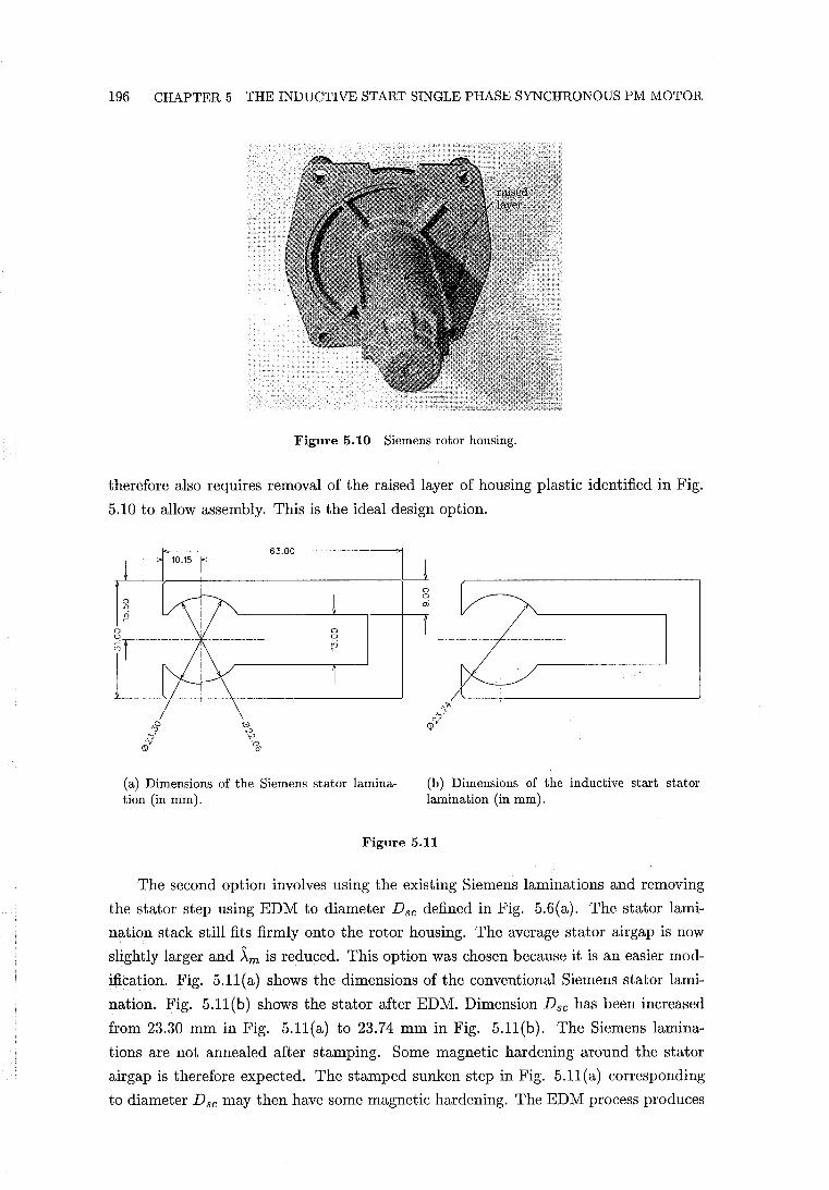
196 CHAPTER 5 THE INDUCTIVE START SINGLE PHASE SYNCHRONOUS PM MOTOR
Figure 5.10 Siemens rotor housing.
therefore also requires removal of the raised layer of housing plastic identified in Fig.
5.10 to allow assembly. This is the ideal design option.
_-----63.00-----~
r--+--~----------~.~
o o ~
(a) Dimensions of the Siemens stator lamination (in mm).
o o oi
(b) Dimensions of the inductive start stator lamination (in mm).
Figure 5.11
The second option involves using the existing Siemens laminations and removing
the stator step using EDM to diameter Dsc defined in Fig. 5.6(a). The stator lami
nation stack still fits firmly onto the rotor housing. The average stator airgap is now
slightly larger and ~m is reduced. This option was chosen because it is an easier mod
ification. Fig. 5.11(a) shows the dimensions of the conventional Siemens stator lami
nation. Fig. 5.11(b) shows the stator after EDM. Dimension Dsc has been increased
from 23.30 mm in Fig. 5.11(a) to 23.74 mm in Fig. 5.11(b). The Siemens lamina
tions are not annealed after stamping. Some magnetic hardening around the stator
airgap is therefore expected. The stamped sunken step in Fig. 5.11(a) corresponding
to diameter Dsc may then have some magnetic hardening. The EDM process produces
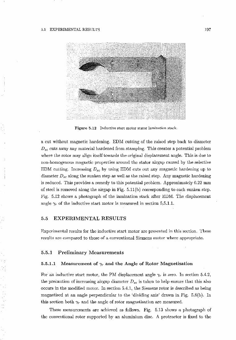
5.5 EXPERIMENTAL RESULTS 197
Figure 5.12 Inductive start motor stator lamination stack.
a cut without magnetic hardening. EDM cutting of the raised step back to diameter
D se cuts away any material hardened from stamping. This creates a potential problem
where the rotor may align itself towards the original displacement angle. This is due to
non-homogenous magnetic properties around the stator airgap caused by the selective
EDM cutting. Increasing Dse by using EDM cuts out any magnetic hardening up to
diameter Dse along the sunken step as well as the raised step. Any magnetic hardening
is reduced. This provides a remedy to this potential problem. Approximately 0.22 mm
of steel is removed along the airgap in Fig. 5.11(b) corresponding to each sunken step.
Fig. 5.12 shows a photograph of the lamination stack after EDM. The displacement
angle "IT of the inductive start motor is measured in section 5.5.1.1.
5.5 EXPERIMENTAL RESULTS
Experimental results for the inductive start motor are presented in this section. These
results are compared to those of a conventional Siemens motor where appropriate.
5.5.1 Preliminary Measurements
5.5.1.1 Measurement of "IT and the Angle of Rotor Magnetisation
For an inductive start motor, the PM displacement angle "IT is zero. In section 5.4.2,
the precaution of increasing airgap diameter D se is taken to help ensure that this also
occurs in the modified motor. In section 5.4.1, the Siemens rotor is described as being
magnetised at an angle perpendicular to the 'dividing axis' drawn in Fig. 5.8(b). In
this section both "IT and the angle of rotor magnetisation are measured.
These measurements are achieved as follows. Fig. 5.13 shows a photograph of
the conventional rotor supported by an aluminium disc. A protractor is fixed to the
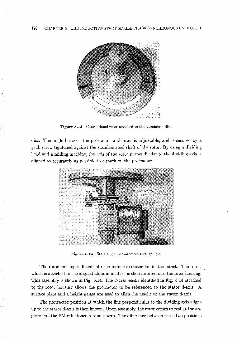
198 CHAPTER 5 THE INDUCTIVE START SINGLE PHASE SYNCHRONOUS PM MOTOR
Figure 5.13 Conventional rotor attached to the aluminium disc.
disc. The angle between the protractor and rotor is adjustable, and is secured by a
grub screw tightened against the stainless steel shaft of the rotor. By using a dividing
head and a milling machine, the axis of the rotor perpendicular to the dividing axis is
aligned as accurately as possible to a mark on the protractor.
Figure 5.14 Start angle measurement arrangement.
The rotor housing is fitted into the inductive stator lamination stack. The rotor,
which is attached to the aligned aluminium disc, is then inserted into the rotor housing.
This assembly is shown in Fig. 5.14. The d-axis needle identified in Fig. 5.14 attached
to the rotor housing allows the protractor to be referenced to the stator d-axis. A
surface plate and a height gauge are used to align the needle to the stator d-axis.
The protractor position at which the line perpendicular to the dividing axis aligns
up to the stator d-axis is then known. Upon assembly, the rotor comes to rest at the an
gle where the PM reluctance torque is zero. The difference between these two positions
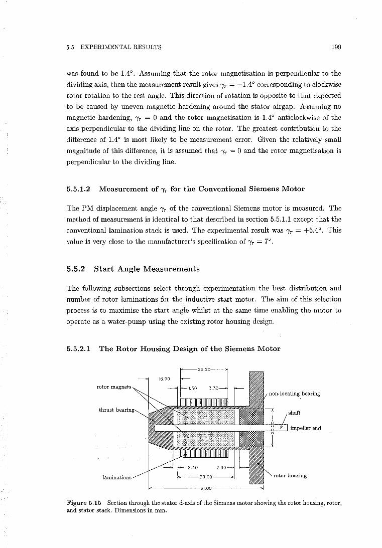
5.5 EXPERIMENTAL RESULTS 199
was found to be 1.40• Assuming that the rotor magnetisation is perpendicular to the
dividing axis, then the measurement result gives "fr = -1.40 corresponding to clockwise
rotor rotation to the rest angle. This direction of rotation is opposite to that expected
to be caused by uneven magnetic hardening around the stator airgap. Assuming no
magnetic hardening, "fr = 0 and the rotor magnetisation is 1.40 anticlockwise of the
axis perpendicular to the dividing line on the rotor. The greatest contribution to the
difference of 1.40 is most likely to be measurement error. Given the relatively small
magnitude of this difference, it is assumed that "fr = 0 and the rotor magnetisation is
perpendicular to the dividing line.
5.5.1.2 Measurement of "fr for the Conventional Siemens Motor
The PM displacement angle "fr of the conventional Siemens motor is measured. The
method of measurement is identical to that described in section 5.5.1.1 except that the
conventional lamination stack is used. The experimental result was "fr = +6.40• This
value is very close to the manufacturer's specification of 'Yr = 70•
5.5.2 Start Angle Measurements
The following subsections select through experimentation the best distribution and
number of rotor laminations for the inductive start motor. The aim of this selection
process is to maximise the start angle whilst at the same time enabling the motor to
operate as a water-pump using the existing rotor housing design.
5.5.2.1 The Rotor Housing Design of the Siemens Motor
16.90
rotor magnets non-locating bearing
shaft
--;~--' impeller end
laminations _--30.00--~ rotor housing
f,E-------61.00--------.;.I
Figure 5.15 Section through the stator d-axis ofthe Siemens motor showing the rotor housing, rotor, and stator stack. Dimensions in mm.
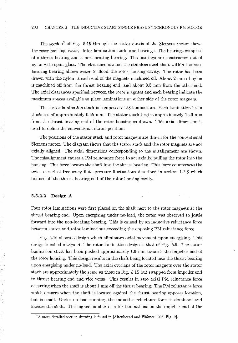
200 CHAPTER 5 THE INDUCTIVE START SINGLE PHASE SYNCHRONOUS PM MOTOR
The section3 of Fig. 5.15 through the stator d-axis of the Siemens motor shows
the rotor housing, rotor, stator lamination stack, and bearings. The bearings comprise
of a thrust bearing and a non-locating bearing. The bearings are constructed out of
nylon with spun glass. The clearance around the stainless steel shaft within the non
locating bearing allows water to flood the rotor housing cavity. The rotor has been
drawn with the nylon at each end of the magnets machined off. About 2 mm of nylon
is machined off from the thrust bearing end, and about 0.5 mm from the other end.
The axial clearances specified between the rotor magnets and each bearing indicate the
maximum spaces available to place laminations on either side of the rotor magnets.
The stator lamination stack is composed of 38 laminations. Each lamination has a
thickness of approximately 0.65 mm. The stator stack begins approximately 16.9 mm
from the thrust bearing end of the rotor housing as drawn. This axial dimension is
used to define the conventional stator position.
The positions of the stator stack and rotor magnets are drawn for the conventional
Siemens motor. The diagram shows that the stator stack and the rotor magnets are not
axially aligned. The axial dimensions corresponding to the misalignment are shown.
The misalignment causes a PM reluctance force to act axially, pulling the rotor into the
housing. This force locates the shaft into the thrust bearing. This force counteracts the
twice electrical frequency fluid pressure fluctuations described in section 1.2.6 which
bounce off the thrust bearing end of the rotor housing cavity.
5.5.2.2 Design A
Four rotor laminations were first placed on the shaft next to the rotor magnets at the
thrust bearing end. Upon energising under no-load, the rotor was observed to jostle
forward into the non-locating bearing. This is caused by an inductive reluctance force
between stator and rotor laminations exceeding the opposing PM reluctance force.
Fig. 5.16 shows a design which eliminates axial movement upon energising. This
design is called design A. The rotor lamination design is that of Fig. 5.9. The stator
lamination stack has been pushed approximately 1.9 mm towards the impeller end of
the rotor housing. This design results in the shaft being located into the thrust bearing
upon energising under no-load. The axial overlaps of the rotor magnets over the stator
stack are approximately the same as those in Fig. 5.15 but swapped from impeller end
to thrust bearing end and vice versa. This results in zero axial PM reluctance force
occurring when the shaft is about 1 mm off the thrust bearing. The PM reluctance force
which occurrs when the shaft is located against the thrust bearing opposes location,
but is small. Under no-load running, the inductive reluctance force is dominant and
locates the shaft. The higher number of rotor laminations on the impeller end of the
3 A more detailed section drawing is found in [Altenbernd and Wahner 1996, Fig. 2).
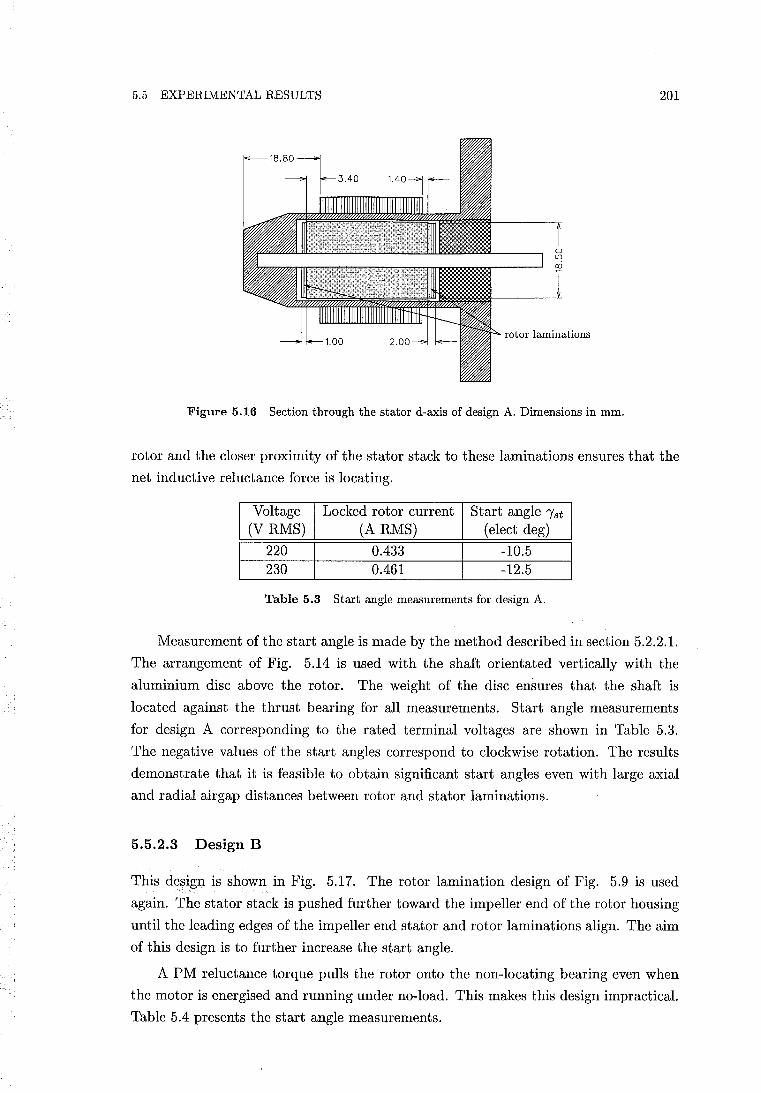
5.5 EXPERIMENTAL RESULTS 201
rotor laminations
Figure 5.16 Section through the stator d-axis of design A. Dimensions in mm.
rotor and the closer proximity of the stator stack to these laminations ensures that the
net inductive reluctance force is locating.
I Voltage
(V RMS)
I 220 230
Locked rotor current (A RMS)
0.433 0.461
Start angle "1st
(elect deg)
-10.5 -12.5
Table 5.3 Start angle measurements for design A.
Measurement of the start angle is made by the method described in section 5.2.2.1.
The arrangement of Fig. 5.14 is used with the shaft orientated vertically with the
aluminium disc above the rotor. The weight of the disc ensures that the shaft is
located against the thrust bearing for all measurements. Start angle measurements
for design A corresponding to the rated terminal voltages are shown in Table 5.3.
The negative values of the start angles correspond to clockwise rotation. The results
demonstrate that it is feasible to obtain significant start angles even with large axial
and radial airgap distances between rotor and stator laminations.
5.5.2.3 Design B
This design is shown in Fig. 5.17. The rotor lamination design of Fig. 5.9 is used
again. The stator stack is pushed further toward the impeller end of the rotor housing
until the leading edges of the impeller end stator and rotor laminations align. The aim
of this design is to further increase the start angle.
A PM reluctance torque pulls the rotor onto the non-locating bearing even when
the motor is energised and running under no-load. This makes this design impractical.
Table 5.4 presents the start angle measurements.
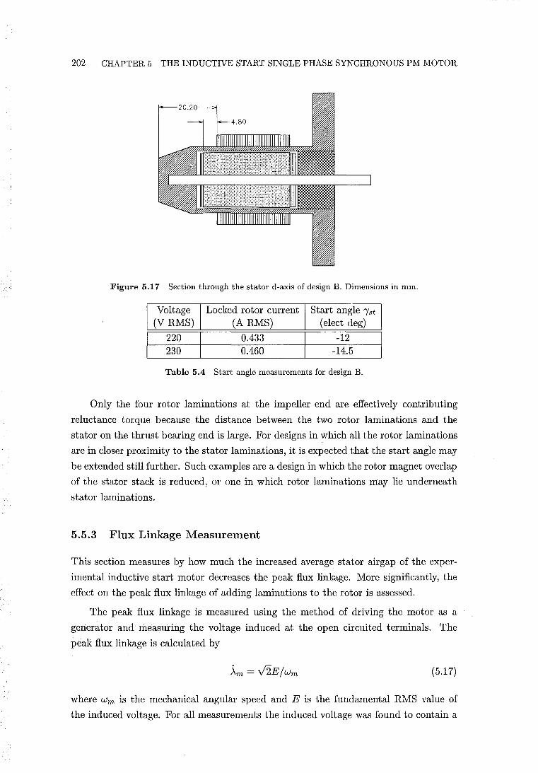
202 CHAPTER 5 THE INDUCTIVE START SINGLE PHASE SYNCHRONOUS PM MOTOR
Figure 5.17 Section through the stator d-axis of design B. Dimensions in mm.
Voltage (V RMS)
220 230
Locked rotor current (A RMS)
0.433 0.460
Start angle 'Yst
(elect deg)
-12 -14.5
Table 5.4 Start angle measurements for design B.
Only the four rotor laminations at the impeller end are effectively contributing
reluctance torque because the distance between the two rotor laminations and the
stator on the thrust bearing end is large. For designs in which all the rotor laminations
are in closer proximity to the stator laminations, it is expected that the start angle may
be extended still further. Such examples are a design in which the rotor magnet overlap
of the stator stack is reduced, or one in which rotor laminations may lie underneath
stator laminations.
5.5.3 Flux Linkage Measurement
This section measures by how much the increased average stator air gap of the exper
imental inductive start motor decreases the peak flux linkage. More significantly, the
effect on the peak flux linkage of adding laminations to the rotor is assessed.
The peak flux linkage is measured using the method of driving the motor as a
generator and measuring the voltage induced at the open circuited terminals. The
peak flux linkage is calculated by
.\m = V2E/wm (5.17)
where Wm is the mechanical angular speed and E is the fundamental RMS value of
the induced voltage. For all measurements the induced voltage was found to contain a
5.5 EXPERIMENTAL RESULTS 203
small component of third harmonic. The magnitude of the third harmonic lay between
3-5% of the fundamental. While strictly the fundamental value of the induced voltage
should be used, instead the true RMS value was used to calculate the flux linkage.
Measurements from three motors are made for the purpose of comparison. These
motors are described as follows:
1. The conventional Siemens motor.
2. A motor using the inductive start stator and the conventional rotor. The stator
lamination stack is located at the conventional axial position. The conventional
rotor does not have rotor laminations. The purpose of this motor is to determine
how the larger stator airgap diameter Dsc reduces the flux linkage in relation to
the conventional motor.
3. The inductive start motor using design A. This measurement allows the influence
of the rotor laminations to be assessed. The rotor laminations 'short circuit' PM
flux at the ends of the magnets creating a reduction in the flux linkage.
The motors tested were driven by a small DC motor at a speed of over 4000 RPM.
Measurements were taken with the shaft of each tested motor located against the thrust
bearing. Experimental results are shown in Table 5.5. The measured value of ~m for the
I Motor I ~m (Volt.sec.) I 1- Conventional Siemens 0.355· 2- Inductive start stator I conventional rotor 0.334 3- Inductive start (design A) 0.321
Table 5.5 Flux linkage measurements.
conventional motor agrees with the manufacturer's specification. For the second motor,
~m is reduced by 6%. In contrast, an increase in ~m of about the same magnitude is
expected for the ideally built inductive start stator design described in section 5.4.2.
This is because the ideal design reduces the average airgap length. By then adding
rotor laminations, ~m is reduced. The difference in flux linkage between the last two
measurements is the amount of PM flux short-circuited by the rotor laminations in
motor 3. The rotor laminations reduce the flux linkage by 4%. Therefore, for an
ideally constructed inductive start motor a small net increase in ~m is possible.
5.5.4 Water Pumping Tests
In this section the inductive start motor (design A) is tested to determine whether it
can start reliably. The water pumping performance of the conventional Siemens motor
and the inductive start motor are compared.
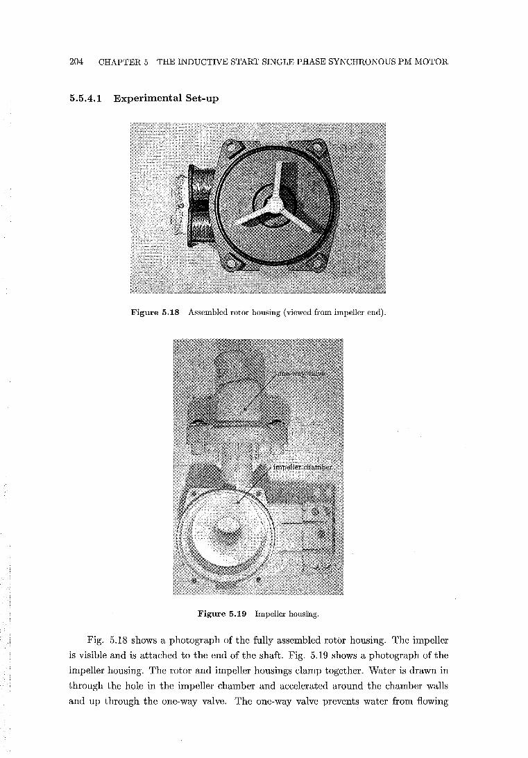
204 CHAPTER 5 THE INDUCTIVE START SINGLE PHASE SYNCHRONOUS PM MOTOR
5.5.4.1 Experimental Set-up
Figure 5.18 Assembled rotor housing (viewed from impeller end).
Figure 5.19 Impeller housing.
Fig. 5.18 shows a photograph of the fully assembled rotor housing. The impeller
is visible and is attached to the end of the shaft. Fig. 5.19 shows a photograph of the
impeller housing. The rotor and impeller housings clamp together. Water is drawn in
through the hole in the impeller chamber and accelerated around the chamber walls
and up through the one-way valve. The one-way valve prevents water from flowing
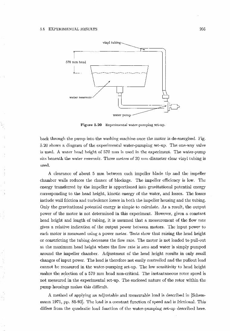
5.5 EXPERIMENTAL RESULTS 205
vinyl tubing
570 mm head
water reservoir
water pump
Figure 5.20 Experimental water-pumping set-up.
back through the pump into the washing machine once the motor is de-energised. Fig.
5.20 shows a diagram of the experimental water-pumping set-up. The one-way valve
is used. A water head height of 570 mm is used in the experiment. The water-pump
sits beneath the water reservoir. Three metres of 20 mm diameter clear vinyl tubing is
used.
A clearance of about 5 mm between each impeller blade tip and the impeller
chamber walls reduces the chance of blockage. The impeller efficiency is low. The
energy transferred by the impeller is apportioned. into gravitational. potential energy
corresponding to the head height, kinetic energy of the water, and losses. The losses
include wall friction and turbulence losses in both the impeller housing and the tubing.
Only the gravitational potential energy is simple to calculate. As a result, the output
power of the motor is not determined in this experiment. However, given a constant
head height and length of tubing, it is assumed that a measurement of the flow rate
gives a relative indication of the output power between motors. The input power to
each motor is measured using a power meter. Tests show that raising the head height
or constricting the tubing decreases the flow rate. The motor is not loaded to pull-out
at the maximum head height where the flow rate is zero and water is simply pumped
around the impeller chamber. Adjustment of the head height results in only small
changes of input power. The load is therefore not easily controlled and the pullout load
cannot be measured in the water-pumping set-up. The low sensitivity to head height
makes the selection of a 570 mm head non-critical. The instantaneous rotor speed is
not measured in the experimental set-up. The enclosed nature of the rotor within the
pump housings makes this difficult.
A method of applying an adjustable and measurable load is described in [Schem
mann 1971, pp. 85-93]. The load is a constant function of speed and is frictional. This
differs from the quadratic load function of the water-pumping set-up described here.
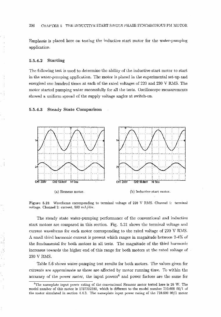
206 CHAPTER 5 THE INDUCTIVE START SINGLE PHASE SYNCHRONOUS PM MOTOR
Emphasis is placed here on testing the inductive start motor for the water-pumping
application.
5.5.4.2 Starting
The following test is used to determine the ability of the inductive start motor to start
in the water-pumping application. The motor is placed in the experimental set-up and
energised one hundred times at each of the rated voltages of 220 and 230 V RMS. The
motor started pumping water successfully for all the tests. Oscilloscope measurements
showed a uniform spread of the supply voltage angles at switch-on.
5.5.4.3 Steady State Comparison
. . . . , .. - ,.. · .. ~ .. . . . . . . . . . . . . . . . . . . . . . .. . . -................... , ... . , ..... , .. , .......... , ............................ . · . . . .. . . . . · . . . - , . . . · . . . - . . . . · . . . .. . . . . · . . . .. . . . . · . .' . .. . , . . · , . . - . . . . · . . . - . . . .
CH1 200V CH2 50.0mV M 5ms CH1 200V . CH2 50.0mV M 5ms
(a) Siemens motor. (b) Inductive start motor.
Figure 5.21 Waveforms corresponding to terminal voltage of 220 V RMS. Channell: terminal voltage. Channel 2: current, 500 mA/div.
The steady state water-pumping performance of the conventional and inductive
start motors are compared in this section. Fig. 5.21 shows the terminal voltage and
current waveforms for each motor corresponding to the rated voltage of 220 V RMS.
A small third harmonic current is present which ranges in magnitude between 2-4% of
the fundamental for both motors in all tests. The magnitude of the third harmonic
increases towards the higher end of this range for both motors at the rated voltage of
230 V RMS.
Table 5.6 shows water-pumping test results for both motors. The values given for
currents are approximate as these are affected by motor running time. To within the
accuracy of the power meter, the input powers4 and power factors are the same for
4The nameplate input power rating of the conventional Siemens motor tested here is 28 W. The model number of this motor is 1737222180, which is different to the model number 710.600 00/1 of the motor simulated in section 4.4.3. The nameplate input power rating of the 710.600 00/1 motor
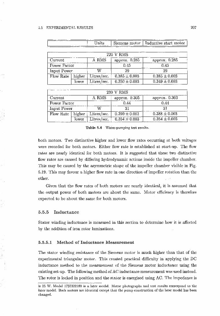
5.5 EXPERIMENTAL RESULTS 207
Units Siemens motor I Inductive start motor
220 V RMS Current ARMS approx. 0.285 approx. 0.285 Power Factor 0.45 0.45 Input Power W 29 29 Flow Rate I higher Litres/sec. 0.385 ± 0.003 0.385 ± 0.003
I lower Litres/sec. 0.350 ± 0.003 0.349 ± 0.003
230 V RMS Current ARMS approx. 0.305 approx. 0.303 Power Factor 0.44 0.44 Input Power W 31 31 Flow Rate I higher Litres/sec. 0.390 ± 0.003 0.388 ± 0.003
I lower Litres/sec. 0.354 ± 0.003 0.354 ± 0.003
Table 5.6 Water-pumping test results.
both motors. Two distinctive higher and lower flow rates occurring at both voltages
were recorded for both motors. Either flow rate is established at start-up. The flow
rates are nearly identical for both motors. It is suggested that these two distinctive
flow rates are caused by differing hydrodynamic actions inside the impeller chamber.
This may be caused by the asymmetric shape of the impeller chamber visible in Fig.
5.19. This may favour a higher flow rate in one direction of impeller rotation than the
other.
Given that the flow rates of both motors are nearly identical, it is assumed that
the output power of both motors are about the same. Motor efficiency is therefore
expected to be about the same for both motors.
5.5.5 Inductance
Stator winding inductance is measured in this section to determine how it is affected
by the addition of iron rotor laminations.
5.5.5.1 Method of Inductance Measurement
The stator winding resistance of the Siemens motor is much higher than that of the
experimental triangular motor. This created practical difficulty in applying the DC
inductance method to the measurement of the Siemens motor inductance using the
existing set-up. The following method of AC inductance measurement was used instead.
The rotor is locked in position and the stator is energised using AC. The impedance is
is 25 W. Model 1737222180 is a later model. Motor photographs and test results correspond to the later model. Both motors are identical except that the pump construction of the later model has been changed.
208 CHAPTER 5 THE INDUCTIVE START SINGLE PHASE SYNCHRONOUS PM MOTOR
calculated from measurement of the RMS voltage and current. After recording of the
RMS voltage and current the stator winding is immediately de-energised and the DC
winding resistance is measured. The inductance is calculated by
(5.18)
5.5.5.2 Experimental Results
Inductance measurements are shown in Fig.s 5.22-5.25. Experimental results are mea
sured over one inductance cycle corresponding to 1800 electrical. The positive angle of
rotation is defined with reference to Fig. 5.6(a). The axis of rotation is viewed from the
thrust bearing end of the rotor and positive rotation is anti-clockwise. The inductance
characteristic about e = 0 is of particular interest for the analysis of starting torque.
The -145° to 35° rotor angle range plotted allows the inductance characteristic through
e = 0 to be clearly observed. Two sets of inductance measurements are taken for each
motor. The first set is taken at locked rotor current corresponding to 220 V RMS.
This measurement is of importance because the inductive reluctance torque at starting
corresponds to locked rotor current. The second set corresponds to the steady state
running current measured in the water-pumping tests described in section 5.5.4. This
measurement is of importance in determining the effects of adding rotor laminations to
steady state performance. For all plots, the values of voltage averaged over an induc
tance cycle, corresponding to locked rotor current, range between 220.5-220.9 V RMS.
The corresponding average locked rotor currents range between 0.414-0.445 ARMS.
For the running current measurements, the average voltages range between 156.5-158
V RMS and the average currents range between 0.277-0.296 A RMS. Polynomial curves
are fitted to the measured points using least squares.
-120 -100 -80 -60 -40 -20 o 20 Rotor angle (elect deg)
Figure 5.22 Conventional Siemens motor inductance waveforms. Locked rotor: Lo = 1.528 H, L = 0.108 H. Running: Lo = 1.655 H, L = 0.061 H.
5.5 EXPERIMENTAL RESULTS 209
Fig. 5.22 shows inductance measurements for the conventional Siemens motor.
The inductance characteristics are predominantly DC with a small quasi-sinusoidal
component. In both curves the saturating effects of the PM rotor flux on inductance,
explained in section 5.2.1, are visible. The saturating effect of the stator current is
also clearly visible. Increasing the current increases saturation which lowers the DC
inductance L o • However, increasing the current increases the modulation amplitude
L. Note that the locked rotor characteristic reaches its minium value at about () = 4°
rather than () = O. This was initially suggested to be caused by the raised steps in the
stator airgap establishing maximum PM flux linkage, and thus maximum saturation,
at the rotor position corresponding to the observed minimum.
-120 -100 -80 -60 -40 -20 Rotor angle (elect deg)
Figure 5.23 Inductive start stator (design A) with the conventional rotor. The inductance waveform corresponds to locked rotor current. Lo = 1.571 H, t = 0.096 H.
Fig. 5.23 shows the locked rotor current inductance characteristic for the motor
composed of the inductive start stator (design A) and the conventional rotor. With
PM displacement angle IT = 0, and the asymmetric airgap eliminated, the inductance
characteristic was expected to be symmetric about () = O. However, the characteristic
reaches its minimum value at a non-zero position. The characteristic is very similar to
the corresponding curve in Fig. 5.22. The slightly larger average stator airgap reduces
saturation resulting in a slightly higher value of L o .
Fig. 5.24 shows inductance measurements for the inductive start motor of design
A. The values of L o are higher than in the previous figures due to the presence of the
rotor laminations. The locked rotor characteristic is similar to that of Fig. 5.23. The
DC value of the additional inductance due to the rotor laminations is obtained as the
difference between the corresponding values of L o in Fig.s 5.23 and 5.24. This yields
Loa = 0.069 H at locked rotor current for design A. A phase shifting of the running
current characteristic is visible. Both the maximum and minimum points are phase
shifted approximately +12°. This phase shift is caused by the position of the rotor
210 CHAPTER 5 THE INDUCTIVE START SINGLE PHASE SYNCHRONOUS PM MOTOR
-80 -60 -40 -20 20 Rotor angle (elect deg)
Figure 5.24 Inductive start (design A) motor inductance waveforms. Locked rotor: Lo = 1.640 H, t = 0.100 H. Running: Lo = 1.757 H, t = 0.052 H.
lamination axis relative to the stator d-axis as rotation occurs. Comparison of both
characteristics in Fig. 5.24 with respect to phase shifting shows that the influence of
the rotor laminations is more predominant at the lower current. This implies that La is greater at lower current for the inductive start motor. This also implies that the
rotor laminations become more saturated as the current is increased.
-120 -100 -80 -60 -40 -20 o 20 Rotor angle (elect deg)
Figure 5.25 Inductive start (design B) motor inductance waveforms. Locked rotor: Lo = 1.648 H, t = 0.100 H. Running: Lo = 1.767 H, t = 0.060 H.
Fig. 5.25 shows inductance measurements for the inductive start motor of design
B. This design yields the largest start angles shown in Table 5.4. The phase shifting
influence of the rotor laminations is most clearly seen in these characteristics, particu
larly in the running current characteristic. From Fig.s 5.23 and 5.25, Loa = 0.077 H at
locked rotor current.
In Fig.s 5.22-5.25, all four locked rotor inductance characteristics appear to have
5.5 EXPERIMENTAL RESULTS 211
similar and small non-zero slopes at e = O. Section 5.5.6 examines the torques at this
position for these motors.
5.5.6 Starting Torque about Rotor and Stator Alignment
The following experiments are undertaken to determine more information about the
PM and inductive reluctance torques about e = O.
The method of start angle measurement described in section 5.2.2.1 is first applied
to the motor composed of the inductive start stator (design A) and the conventional
rotor. Before the stator winding is energised, the rotor is at rest at e = "'Ir = 0
and the PM reluctance torque is zero. Upon energising at 220 V RMS no rotation
occurs. The zero rotation implies that the inductive reluctance torque is also zero at
e = O. In section 5.5.2, it is shown that the inductive start motors of designs A and
B have non-zero start angles. Inductive reluctance torques at e = 0 must therefore be
present in both these motors to achieve the non-zero start angles. The design A and B
start angle tests, and the test described above, show that the locked rotor inductance
characteristics of Fig.s 5.22-5.25 do not give reliable indications of the presence of
inductance reluctance torque at e = o.
I stable I unstable I stable I PM reluctance torque, Tr 0 90 180 PM and inductive reluctance torques 0 88.5 179 at locked rotor current, Tr + Tind c
Table 5.7 Rest angle measurements for the motor composed of the inductive start stator (design A) and the conventional rotor. Angles in elect. degrees.
In the example of Fig. 5.5 corresponding to an ideal inductive start motor, torque
waveforms Tind c and Tr are shown in anti-phase. For the motor composed of the
inductive start stator and the conventional rotor, these torques are also present but
Tind a is eliminated. This allows an opportunity to determine experimentally whether Tr
dominants Tind c under locked rotor current. To do this, the PM reluctance rest angles
over a PM reluctance cycle are first measured. These angles are shown in Table 5.7 and
agree with theory. The large artificial moment of inertia of the start angle measurement
method is then attached to the shaft. The rest angles corresponding to locked rotor
current are then measured. The rest angles correspond to the superposition of Tind c and
Tr . These rest angles are also shown in Table 5.7. These results show that the direction
of torque and the rest angles remain essentially unchanged. This demonstrates that Tr
dominants Tind c under locked rotor current over all rotor positions for an inductive start
motor. For example, at about e = 90°, the inductance is maximised and is therefore
assumed to provide a stable rest position for Tindc' However, Table 5.7 shows that
this position remains unstable corresponding to the dominance of the PM reluctance
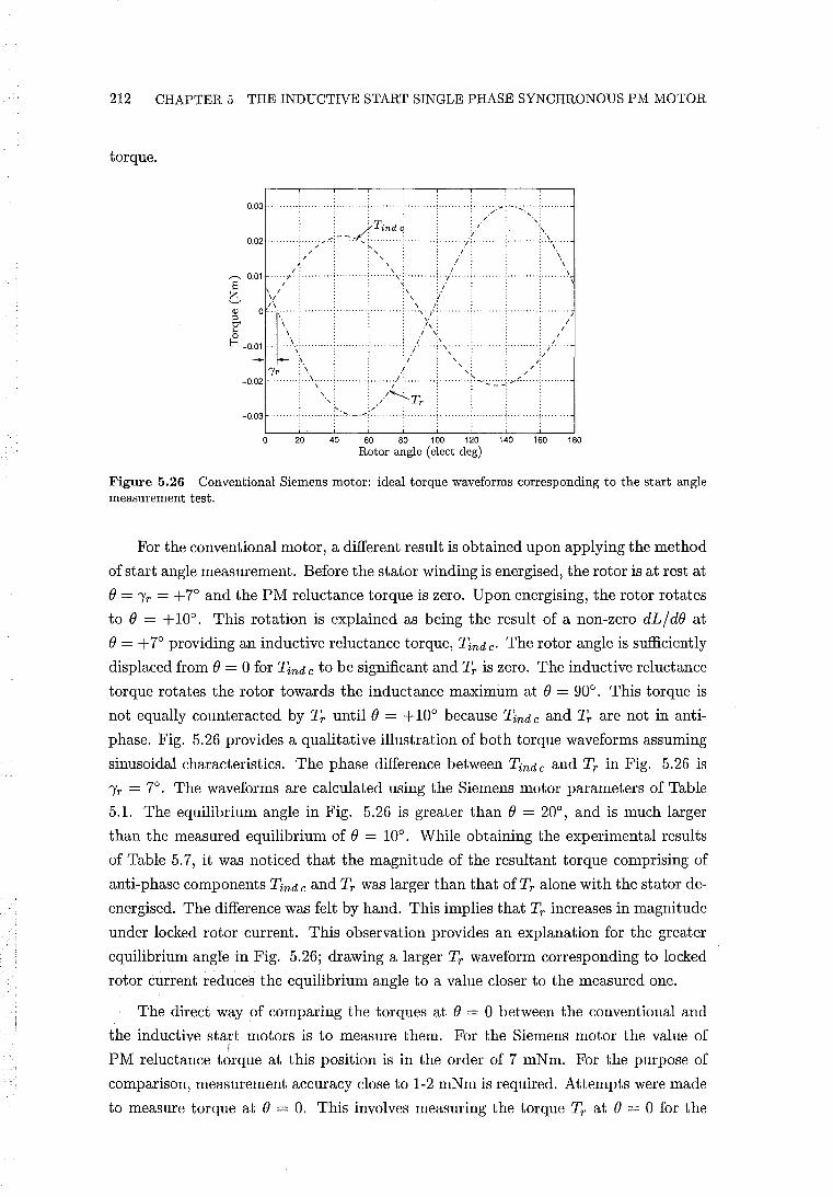
212 CHAPTER 5 THE INDUCTIVE START SINGLE PHASE SYNCHRONOUS PM MOTOR
torque.
---.. 0.01 S e ~ ~ -0.01
o 180
Figure 5.26 Conventional Siemens motor: ideal torque waveforms corresponding to the start angle measurement test.
For the conventional motor, a different result is obtained upon applying the method
of start angle measurement. Before the stator winding is energised, the rotor is at rest at
e = 'Yr = +7° and the PM reluctance torque is zero. Upon energising, the rotor rotates
to e = +10°. This rotation is explained as being the result of a non-zero dL / de at
e = +7° providing an inductive reluctance torque, Tind c' The rotor angle is sufficiently
displaced from e = 0 for Tind c to be significant and Tr is zero. The inductive reluctance
torque rotates the rotor towards the inductance maximum at e = 90°. This torque is
not equally counteracted by Tr until e = +10° because Tind c and Tr are not in anti
phase. Fig. 5.26 provides a qualitative illustration of both torque waveforms assuming
sinusoidal characteristics. The phase difference between Tind c and Tr in Fig. 5.26 is
'Yr = 7°. The waveforms are calculated using the Siemens motor parameters of Table
5.1. The equilibrium angle in Fig. 5.26 is greater than e = 20°, and is much larger
than the measured equilibrium of e = 10°. While obtaining the experimental results
of Table 5.7, it was noticed that the magnitude of the resultant torque comprising of
anti-phase components Tindc and Tr was larger than that ofTr alone with the stator de
energised. The difference was felt by hand. This implies that Tr increases in magnitude
under locked rotor current. This observation provides an explanation for the greater
equilibrium angle in Fig. 5.26; drawing a larger Tr waveform corresponding to locked
rotor current reduces the equilibrium angle to a value closer to the measured one.
The direct way of comparing the torques at e = 0 between the conventional and
the inductive start motors is to measure them. For the Siemens motor the value of
PM reluctance t~rque at this position is in the order of 7 mNm. For the purpose of
comparison, measurement accuracy close to 1-2 mNm is required. Attempts were made
to measure torque at e = O. This involves measuring the torque Tr at e = 0 for the
5.6 CONCLUSIONS 213
conventional motor with the stator winding de-energised. It also involves using the
start angle measurement set-up to measure Tind a at e = 0 at locked rotor current for
the inductive start motor. However, for each experiment it was found to be too difficult
to obtain consistent measurements. This is due to the small magnitude of the torque
required to be measured. However, 'finger pressure' measurement of the torques of
both motors suggests similar magnitudes at e = O. The finger pressure torque felt from
the inductive start motor is an averaged value, and not the peak value.
5.6 CONCLUSIONS
A single phase synchronous PM motor which uses inductive reluctance torque to facil
itate starting has been proposed. A theoretical model has been developed. A practical
design for this inductive start motor has been developed and tested. It has been demon
strated through the measurement of the start angle that the inductive start motor offers
an alternative starting mechanism to that of the conventional designs. For a water
pumping application, the inductive start motor developed has been shown to achieve
the same water-pumping performance as the conventional motor.
A comparison of the inductance characteristics for the conventional and unidirec
tional motors shows that the modulation of the inductances is similar. This suggests
that the inductance of the unidirectional motor may also be assumed to be constant for
the purpose of simulating the unidirectional motor at synchronous speed. This assump
tion also allows the conventional synchronous performance equations to be applied to
the unidirectional motor.
A description of advantages and disadvantages of the inductive start motor with
respect to the conventional motor is made as follows. The advantages are described first.
The inductive start motor has the flexibility to increase the starting torque at the stator
and rotor alignment position, and also the start angle, by adding more laminations to
the rotor. The start angles ofthe inductive start motor designs have been demonstrated
to be significantly larger than the PM displacement angle of the conventional Siemens
motor. The inductive start motor simplifies the stator lamination design by eliminating
the conventional asymmetric airgap steps, or alternative saturating notches. For the
specific example of the Siemens motor, the manufacture of both the stator laminations
and the rotor housing are simplified by the elimination of the airgap steps. The rotor
housing is simplified through the removal of the raised layer of plastic identified in Fig.
5.10. Filling in of the conventional asymmetric airgap steps, or alternative saturating
notches, increases the PM flux linkage. However, for the experimental inductive start
motor, the peak flux linkage was decreased by cutting out the raised steps. As was
observed in section 5.5.3, this resulted in a 6% reduction in peak flux linkage. As
discussed in section 5.4.2, the ideal inductive start stator design fills in the sunken steps
rather than cutting out the raised steps. The airgap diameter of the inductive start
214 CHAPTER 5 THE INDUCTIVE START SINGLE PHASE SYNCHRONOUS PM MOTOR
stator is then minimised. In this case a gain of about 6% will be assumed. However,
this increase is reduced by the short circuiting effect of adding rotor laminations. This
reduction was 4%. Thus for an ideally modified Siemens motor, it is expected that a
small net increase in peak flux linkage is likely to occur.
Disadvantages are described as follows. The rotor moment of inertia is increased
by the addition of rotor laminations. However, the number of rotor laminations re
quired contributed to only a very small increase in rotor inertia. The construction of
the rotor is more complex. From a manufacturing perspective, a reliable method of
aligning and securing the rotor laminations at the correct angle with respect to the
rotor magnetisation is required. This might be achieved more easily by attaching the
rotor laminations before magnetisation. Before a water pumping application can be
considered, a reliable method of water proofing the rotor laminations is required to
prevent rusting. A nylon enclosure which seals and secures the rotor laminations might
offer a possible solution.
In section 5.5.5.2, the DC value of inductance is shown to increase by the addition
of rotor laminations. It is difficult to predict the impact of adding rotor laminations
without first considering saturation levels and building the ideal inductive start motor.
Both the PM flux, and the inductance increase. The pullout torque may be expected
to remain approximately the same for comparative conventional and inductive start
designs.
Chapter 6
CONCLUSIONS AND SUGGESTIONS FOR FURTHER RESEARCH
This chapter summarises the conclusions presented in Chapters 2-5. Suggestions for
further research are also included.
In Chapter 2, it has been shown how to determine torques or forces in machines
containing permanent magnets using energy methods. This is achieved by first deter
mining the energy stored in the electromechanical coupling field. In doing this, the
energy stored in a PM system has been defined. The energy-co energy relationship for
a PM system has been determined. It is proven that WI (i=O) = -W(i=O) for a PM
system having arbitrary magnetisation characteristics and zero currents. A specific
example of a PM system comprising of a PM material having a linear demagnetisa
tion characteristic, and an airgap or linear region l for zero currents, is presented. It
is shown that the stored energy or coenergy of the magnet should not be neglected
in the calculation of reluctance torque. It has been shown how residual magnetism
can be incorporated into classical electromechanical coupling theory. It is therefore
shown how general equations for torques and forces, which include non-zero currents,
can be derived for PM systems from classical electromechanical coupling theory. In
doing this, it is proven that the relationship W + WI = Ai holds for a PM system. The
approximation made in deriving a simplified equation for torque in a linear system is
described. The validity of the first quadrant representation of the rate of change of
co energy within a PM material, relevant to CAD systems, is also demonstrated. This
work establishes a solid theoretical base for a selection of torque or force equations used
by both machine and CAD system designers, as well as some less obvious equations.
In Chapter 3, an analytical method of calculating PM reluctance torque has been
developed. The method uses an elementary expression for the magnetic field to obtain
the stored energy. This enables an analytical expression for the reluctance torque
waveform to be obtained. Because the stored energy is an analytical expression, the
error in taking the derivative with respect to rotational displacement to obtain the
torque is zero. It is shown that the method does not require the magnetic field to
be accurately resolved into its normal and tangential components, unlike the Maxwell
216 CHAPTER 6 CONCLUSIONS AND SUGGESTIONS FOR FURTHER RESEARCH
stress method. This is possible because of the global nature of stored energy. The
method is demonstrated to provide a powerful and fast design tool. The method can be
generally applied to reluctance torque problems where the airgap is reasonably smooth.
However, application of the method is likely to exclude cogging torque problems due
to stator slotting because the field is unlikely to be described with sufficient accuracy.
The remaining conclusions concern the three novel single phase PM motors de
scribed in Chapters 3-5.
Chapter 3 has also examined the triangular motor which implements the constant
instantaneous torque concept described in Chapter 1. This concept uses a specially
designed PM reluctance torque to flatten out the twice electrical frequency torque
pulsation characteristic of single phase machines. Alternatively explained in terms
of counter rotating field theory, the PM reluctance torque cancels out the effect of
the backward rotating stator field. The triangular motor requires a triangular PM
reluctance torque, and a trapezoidal back EMF. It is shown that it is possible to
design a triangular reluctance torque. The required reluctance torque and EMF are
implemented adequately by the experimental axial flux double air gap motor. This
demonstrates that it is possible to produce a high quality torque in a PM motor using
only a single phase winding. A single phase DC to AC inverter and rotor position
sensors are required to drive the triangular motor. In section 1.2.7, the characteristics
which limit the application of the conventional single phase synchronous PM motor have
been listed. A triangular motor, in combination with an electronic driver, eliminates all
ofthese limiting characteristics. But it has been noted in section 3.9 that the triangular
motor is unlikely to be able to compete in general with brushless PM motor drives.
In Chapter 4, the concept of the unidirectional motor has been developed. The
unidirectional motor achieves a constant instantaneous torque with the aid of a PM
reluctance torque of sinusoidal shape. The unidirectional motor is directly connected to
an AC supply, and is described as being a special case of the conventional single phase
synchronous PM motor. The backward instability ratio is proposed as an approximate
measure of the ability of a unidirectional motor to self correct its direction of rotation.
Two theoretical unidirectional motor designs which use this ratio as a design guide have
been completed. The first motor design uses a single pole pair and a higher grade of
PM material, which is bonded Nd-Fe-B. The second design uses multiple pole pairs and
ferrite grade magnets. These designs employ a manufacturable construction consisting
of parallel magnetised rotor poles and closed stator slots, in a radial airgap. A theoret
ical model is developed for calculating the EMF/torque function, which shows that as
the number of pole pairs increases, a parallel magnetisation more closely approximates
a radial magnetisation. This results in the third harmonic in the EMF/torque function
becoming more significant for pole pair numbers greater than one. The unidirectional
motor concept is shown to be simply implemented in the 2-pole design described above.
In this 2-pole design, PM reluctance torque and EMF/torque function waveforms of
217
high sinusoidal quality are shown to be achievable. Simulation results show that the
2-pole motor achieves unidirectional motion without speed ripple at the rated load and
voltage. Unidirectional motion is also shown to occur over a satisfactory range of start
ing loads. The unidirectional motor eliminates several of the limiting characteristics
listed in section 1.2.7: the unidirectional motor self corrects its direction of rotation,
the availability of rated torque at all rotor angles ensures initial starting capability, and
speed ripple, which can cause noise problems, is either eliminated or reduced. How
ever, it is shown that an even tighter inertial constraint than the conventional motor
is required to create sufficient backward instability for unidirectional motion.
There is considerable scope for further unidirectional motor research and develop
ment. The theory and ideas presented require experimental validation. Section 4.11.1
describes two unidirectional motor designs which are considered to be more practical
for production. These designs use 2-pole ferrite rotors. The first design uses a small
enough rotor diameter to ensure sufficient backward instability. The second design uses
a larger rotor diameter, and has the same inertial constraint on rotor diameter as the
conventional 2-pole motor. In this design, a mechanical direction correcting device is
required, and speed ripple is eliminated at the rated load, reducing noise. A third pos
sibility is to remove the inertial constraint altogether by using the simple triac circuit
described in section 1.3.1. The unidirectional motor may be more attractive to use
in such a triac circuit because it offers a higher quality torque than the conventional
motor.
In Chapter 5, a single phase synchronous PM motor which uses inductive reluctance
torque to facilitate starting has been proposed. A theoretical model has been developed.
A practical design for this inductive start motor, which uses iron rotor laminations, has
been developed and tested. It has been demonstrated through the measurement of
the start angle that the inductive start motor offers an alternative starting mechanism
to that of the conventional designs. For a water-pumping application, the inductive
start motor was shown to achieve the same steady state water-pumping performance
as the conventional motor. The start angle was shown to be up to twice as large as the
displacement angle of the conventional motor.
For further research, the development of a set of equations of motion which reliably
model the starting transient of the inductive start motor would be of use. Unlike the
conventional model, the inductance cannot be assumed to be constant. Detailed exper
imental measurements of starting transients are first required before the development
of such a model can be attempted. Experimental validation that the motor can be
modelled using the conventional equations under steady state running is also required.
Appendix A
PUBLISHED PAPERS
STRAHAN, R.J., 'Energy conversion by nonlinear permanent magnet machines', lEE
Proc.-Electr. Power Appl., Vol. 145, No.3, May 1998, pp.193-198.
STRAHAN, R.J. AND WATSON, D.B., 'Effects of airgap and magnet shapes on per
manent magnet reluctance torque', IEEE Trans. Magn., Vol. 35, No.1, January 1999,
pp.536-542.
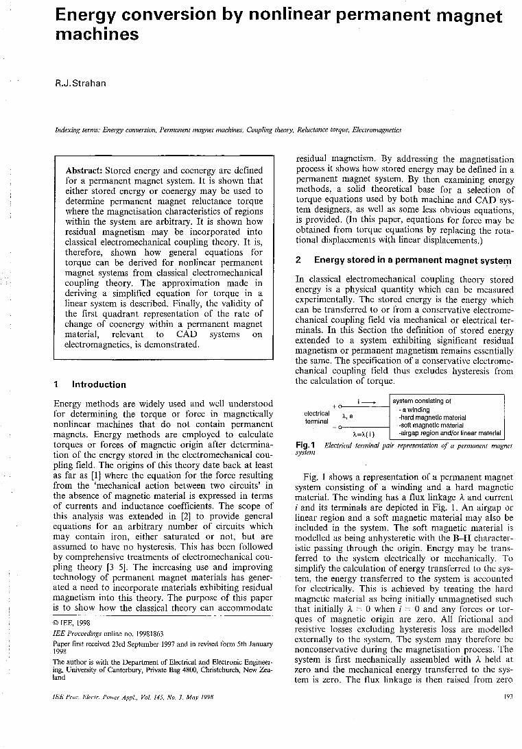
Energy conversion by nonlinear permanent magnet machines
R.J. Strahan
Indexing terms: Energy conversion, Permanent magnet machines, Coupling theory, Reluctance torque, Electromagnetics
Abstract: Stored energy and coenergy are defined for a permanent magnet system. It is shown that either stored energy or coenergy may be used to determine permanent magnet reluctance torque where the magnetisation characteristics of regions within the system are arbitrary. It is shown how residual magnetism may be incorporated into classical electromechanical coupling theory. It is, therefore, shown how general equations for torque can be derived for nonlinear permanent magnet systems from classical electromechanical coupling theory. The approximation made in deriving a simplified equation for torque in a linear system is described. Finally, the validity of the first quadrant representation of the rate of change of coenergy within a permanent magnet material, relevant to CAD systems on electromagnetics, is demonstrated.
1 Introduction
Energy methods are widely used and well understood for determining the torque or force in magnetically nonlinear machines that do not contain permanent magnets. Energy methods are employed to calculate torques or forces of magnetic origin after determination of the energy stored in the electromechanical coupling field. The origins of this theory date back at least as far as [1] where the equation for the force resulting from the 'mechanical action between two circuits' in the absence of magnetic material is expressed in terms of currents and inductance coefficients. The scope of this analysis was extended in [2] to provide general equations for an arbitrary number of circuits which may contain iron, either saturated or not, but are assumed to have no hysteresis. This has been followed by comprehensive treatments of electromechanical coupling theory [3-5]. The increasing use and improving technology of permanent magnet materials has generated a need to incorporate materials exhibiting residual magnetism into this theory. The purpose of this paper is to show how the classical theory can accommodate
© IEE, 1998
lEE Proceedings online no. 19981863
Paper first received 23rd September 1997 and in revised form 5th January 1998
The author is with the Department of Electrical and Electronic Engineering, University of Canterbury, Private Bag 4800, Christchurch, New Zealand
lEE Proe.-Eleelr. Power Appl., Vol. 145. No.3. May 1998
residual magnetism. By addressing the magnetisation process it shows how stored energy may be defined in a permanent magnet system. By then examining energy methods, a solid theoretical base for a selection of torque equations used by both machine and CAD system designers, as well as some less obvious equations, is provided. (In this paper, equations for force may be obtained from torque equations by replacing the rotational displacements with linear displacements.)
2 Energy stored in a permanent magnet system
In classical electromechanical coupling theory stored energy is a physical quantity which can be measured experimentally. The stored energy is the energy which can be transferred to or from a conservative electromechanical coupling field via mechanical or electrical terminals. In this Section the definition of stored energy extended to a system exhibiting significant residual magnetism or permanent magnetism remains essentially the same. The specification of a conservative electromechanical coupling field thus excludes hysteresis from the calculation of torque.
i -----+ system consisting of electrical + o-----j - a winding terminal A, e -hard magnetic material
·soft magnetic material A=A(i) -airgap region and/or linear material
Fig.1 Electrical terminal pair representation of a permanent magnet system
Fig. 1 shows a representation of a permanent magnet system consisting of a winding and a hard magnetic material. The winding has a flux linkage A and current i and its terminals are depicted in Fig. 1. An airgap or linear region and a soft magnetic material may also be included in the system. The soft magnetic material is modelled as being an hysteretic with the B-H characteristic passing through the origin. Energy may be transferred to the system electrically or mechanically. To simplify the calculation of energy transferred to the system, the energy transferred to the system is accounted for electrically. This is achieved by treating the hard magnetic material as being initially unmagnetised such that initially A = 0 when i = 0 and any forces or torques of magnetic origin are zero. All frictional and resistive losses excluding hysteresis loss are modelled externally to the system. The system may therefore be nonconservative during the magnetisation process. The system is first mechanically assembled with A held at zero and the mechanical energy transferred to the system is zero. The flux linkage is then raised from zero
193
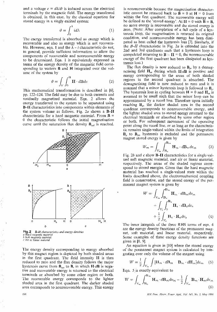
and a voltage e = d?Jdt is induced across the electrical terminals by the magnetic field. The energy transferred is obtained, in this case, by the classical equation for stored energy in a singly excited system:
() = loA idA (1)
The energy transferred is absorbed as energy which is recoverable and also as energy which is not recoverable. However, eqn. 1 and the A - i characteristic do not, in general, provide sufficient information to allow the components of recoverable and nonrecoverable energy to be determined. Eqn. I is equivalently expressed in terms of the energy density of the magnetic field corresponding to vectors Band H integrated over the volume of the system by
() = lloB H . dBdv (2)
This mathematical transformation is described in [6], pp. 122-124. The field may be due to both currents and residually magnetised material. Eqn. 2 allows the energy transferred to the system to be separated using B-H characteristics into components within elements of the system volume as follows. Fig. 2a shows a B-H characteristic for a hard magnetic material. From B = o the characteristic follows the initial magnetisation curve until the saturation flux density Bsal is reached.
B
b
Fig.2 B--H characteristics and energy densities a Hard magnetic material b Soft magnetic material c Air or linear material
o
The energy density corresponding to energy absorbed by this magnet region is depicted by both shaded areas in the first quadrant. The field intensity H is then reduced to zero and the flux density follows the major hysteresis curve from Bsal to B,. in which H·dB is negative and recoverable energy is returned to the electrical terminals or absorbed by some other region or both. The recoverable energy corresponds to the lighter shaded area in the first quadrant. The darker shaded area corresponds to nonrecoverable energy. This energy
194
is nonrecoverable because the magnetisation characteristic cannot be retraced back to B == 0 at H = 0 from within the first quadrant. The recoverable energy will be defined as the 'stored energy'. At H = 0 with B = B,. no more energy is recoverable and the stored energy is zero. (Note: After completion of a full cycle of a hysteresis loop, the magnetisation is returned its original condition, and nonrecoverable energy has been dissipated as heat called the hysteresis loss [7]. Similarly, if the B-H characteristic in Fig. 2a is extended into the 2nd and 3rd quadrants such that a hysteresis loop is compeleted returning to B = H == 0, the nonrecoverable energy of the first quadrant has been dissipated as hysteresis loss.)
The flux density is now reduced to Bill by a demagnetising field Hill during which UdB is positive and energy corresponding to the areas of both shaded regions in the second quadrant is absorbed. The demagnetising field is now reduced to zero and it is assumed that a minor hysteresis loop is followed to Bo.
The hysteresis loss in cycling between H = 0 and Hill is assumed to be small such that the minor loop can be approximated by a recoil line. Therefore upon initially reaching Boo the darker shaded area in the second quadrant corresponds to nonrecoverable energy, and the lighter shaded area to stored energy returned to the electrical terminals or absorbed by some other region or both. For subsequent movement of the operating point along the recoil line, or as long as the characteristic remains single-valued within the limits of integration Bo to Bm, hysteresis is excluded and the permanent magnet stored energy is given by
llBm
Wrn = Hm' dBmdvrn v'n Bo
(3)
Fig. 2b and c show B-H characteristics for a single-valued soft magnetic material, and air or linear material, respectively. The areas of the shaded regions correspond to stored energies. Given that the hard magnetic material has reached a single-valued state within the limits described above, the electromechanical coupling field is conservative, and the stored energy of the permanent magnet system is given by
W = 1 iBm Hrn . dBrndvrn Vm Bo
riBs + iT" Hs . dBsdvs Vs 0
+ ~ r Ba' Hadva (4) 2 iVa
The inner integrals of the three RHS terms of eqn. 4 are the energy density functions of the permanent magnet, soft material, and linear material, respectively. Some examples of these energy density functions are given in [8, 9].
An equation is given in [10] where the stored energy of the permanent magnet system is calculated by integrating over only the volume of the magnet using
W = ~ iv", J [Hm . dBm - Bm . dHm]dvm (5)
Eqn. Sis exactly equivalent to
W = l iBm Hm ·dBmdvm - ~ l Bm . Hmdvm Vm Bo 2 \I",
(6)
lEE Proc.-Eleclr. Power Appl .. Vol. 145. No.3. May 1998
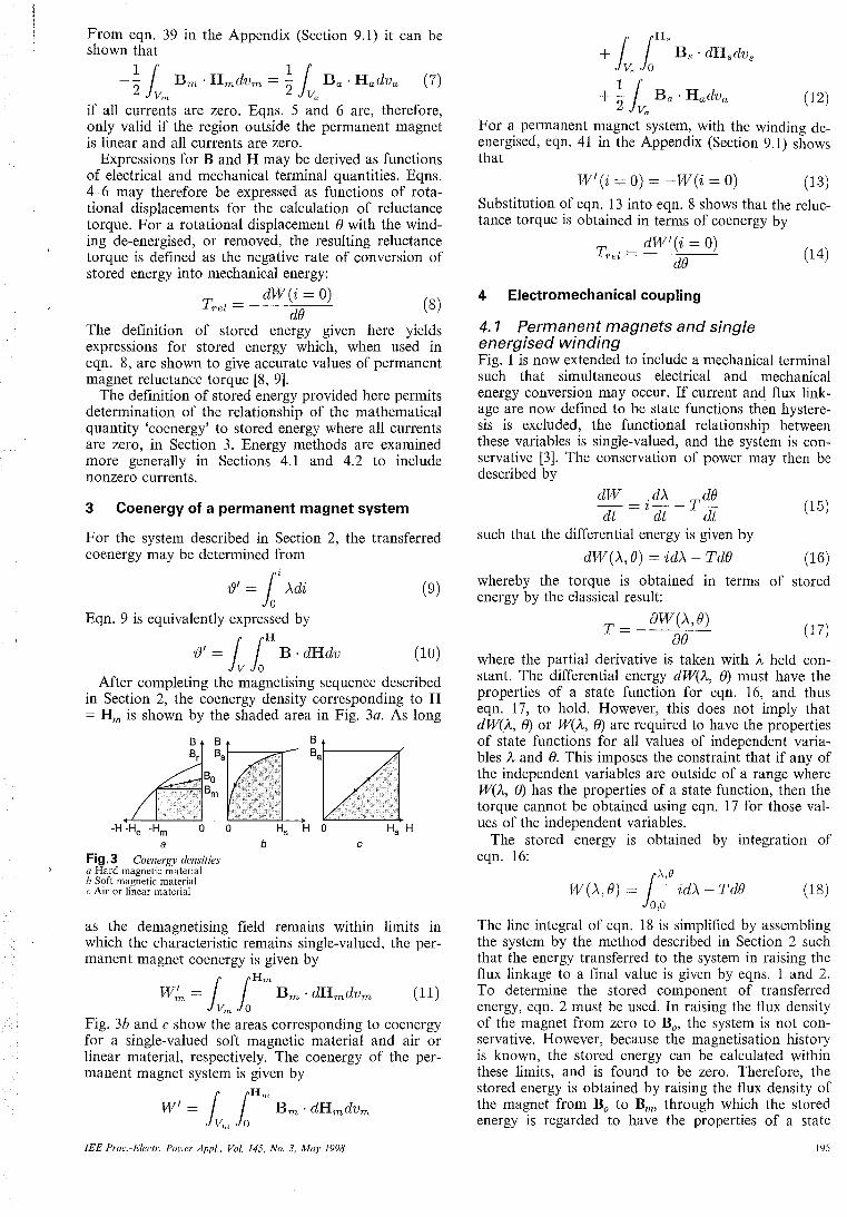
From eqn. 39 in the Appendix (Section 9.1) it can be shown that
-~ J Bm . Hmdvm = ~J Ba . Hadva ~n Va
(7)
if all currents are zero. Eqns. 5 and 6 are, therefore, only valid if the region outside the permanent magnet is linear and all currents are zero.
Expressions for Band H may be derived as functions of electrical and mechanical terminal quantities. Eqns. 4-6 may therefore be expressed as functions of rotational displacements for the calculation of reluctance torque. For a rotational displacement 8 with the winding de-energised, or removed, the resulting reluctance torque is defined as the negative rate of conversion of stored energy into mechanical energy:
T __ dW(i=O) rel - dB (S)
The definition of stored energy given here yields expressions for stored energy which, when used in eqn. 8, are shown to give accurate values of permanent magnet reluctance torque [8, 9].
The definition of stored energy provided here permits determination of the relationship of the mathematical quantity 'coenergy' to stored energy where all currents are zero, in Section 3. Energy methods are examined more generally in Sections 4.1 and 4.2 to include nonzero currents.
3 Coenergy of a permanent magnet system
For the system described in Section 2, the transferred co energy may be determined from
73' = 1i Adi (9)
Eqn. 9 is equivalently expressed by
73' = llH B· dHdv (10)
After completing the magnetising sequence described in Section 2, the co energy density corresponding to H = Hm is shown by the shaded area in Fig. 3a. As long
a Fig.3 Coenergy densities a Hard magnetic material b Soft magnetic material c Air or linear material
b c
as the demagnetising field remains within limits in which the characteristic remains single-valued, the permanent magnet co energy is given by
J lHm
W:n = Bm . dHmdvm Vm a
(11)
Fig. 3b and c show the areas corresponding to co energy for a single-valued soft magnetic material and air or linear material, respectively. The coenergy of the permanent magnet system is given by
{ {Hm W' = I" in Bm . dHmdvm
Vm 0
lEE Proc.-Elec/I'. POlI'er Appl .. Vol. 145, No.3, May 1998
J {H.<
+ in Bs . dHsdvs \1< 0
+ ~ J Ba' Hadva (12) Va
For a permanent magnet system, with the winding deenergised, eqn. 41 in the Appendix (Section 9.1) shows that
W'(i = 0) = -Wei = 0) (13) Substitution of eqn. 13 into eqn. 8 shows that the reluctance torque is obtained in terms of co energy by
dW'(i = 0) Trel = (14)
de
4 Electromechanical coupling
4. 1 Permanent magnets and single energised winding Fig. 1 is now extended to include a mechanical terminal such that simultaneous electrical and mechanical energy conversion may occur. If current and flux linkage are now defined to be state functions thfm hysteresis is excluded, the functional relationship between these variables is single-valued, and the system is conservative [3]. The conservation of power may then be described by
dW = idA _ Tde dt dt dt
(15)
such that the differential energy is given by
dW(A, e) = idA - Tde (16)
whereby the torque is obtained in energy by the classical result:
T = _ aW(A,e) ae
terms of stored
(17)
where the partial derivative is taken with A held constant. The differential energy dW(A, 8) must have the properties of a state function for eqn. 16, and thus eqn. 17, to hold. However, this does not imply that dW(A, 8) or W(A, 8) are required to have the properties of state functions for all values of independent variables A and 8. This imposes the constraint that if any of the independent variables are outside of a range where W(A, 8) has the properties of a state function, then the torque cannot be obtained using eqn. 17 for those values of the independent variables.
The stored energy is obtained by integration of eqn. 16:
()..,e W(A, e) = in idA - TdB
0,0 (IS)
The line integral of eqn. 18 is simplified by assembling the system by the method described in Section 2 such that the energy transferred to the system in raising the flux linkage to a final value is given by eqns. 1 and 2. To determine the stored component of transferred energy, eqn. 2 must be used. In raising the flux density of the magnet from zero to Ba> the system is not conservative. However, because the magnetisation history is known, the stored energy can be calculated within these limits, and is found to be zero. Therefore, the stored energy is obtained by raising the flux density of the magnet from Bo to Bill, through which the stored energy is regarded to have the properties of a state
195
function and is given by eqn. 4. The stored ene~gy ~s regarded to have the properties ?f a ~ta~e ~un.ctlOn If the demagnetising field Hm remaInS wIthIn 1.lmits. such that the demagnetising characteristic remaInS SIngl~valued. The state function requirement of eqn. 16 IS therefore satisfied allowing the torque of the permanent magnet system to be given by eqn. 17. . .
In a conservative system the relatIOnshIp between energy and co energy is given by a Legendre transformation:
W'=Ai-W (19)
which is necessarily shown in the Appendix (Section 9.2) (by setting J = 1) to hold for a permanent mag~et system. This relationship allo,:"s. the torque to be eqUIValently expressed by the remaInIng claSSIcal results:
_ aW'(A,e) _ A ai(A,e) T - ae ae (20)
aW'(i, e) T= ae (21)
. aA(i, e) aW(i, e) T = ~ ae - ae (22)
where the partial derivatives of eqns. 21 and 22 are taken with i held constant. The co energy W for a permanent magnet system is obtained by eqn. 12. Eqns. 17, 20-22 each allow the torque to be obtained for a nonlinear permanent magnet system. For these equations, it is essential to hold the independent variable A or i constant while taking the partial derivative analytically or numerically. Note that eqns. 17 and 21 are more general forms of eqns. 8 and 14.
4.2 Permanent magnets and multiple energised windings . Fig. 1 is now extended to include J elec~ncal a~d ~ mechanical terminal pairs. The energy differentlal IS then given by
J K
dW = I.: ijdAj - I.: Tkdek (23) j=l k=l
whereby the torque obtained at the kth mechanical terminal is obtained in terms of stored energy by
aW(A, e) Tk = - 8B
k (24)
where (A, a) is now an abbreviation for (AJ, ... , AJ; aJ, ... , aK). If the system is assembled in an analogous manner to that described in Section 2, the energy transferred to the system in raising the flux linkages to their final values is given by eqn. 2 and also by
rA1 , ... ,A,T J .
73 = In I.: ~jdAj 0, ... ,0 j=l
(25)
where & = iiAI' ... , AJ; aJ, ... , aK). If there i~ no hard magnetic material in the system and the functIOnal relationships between variables is single-valued, eqn. 25 obtains the stored energy as a state function given that independence of path is demonstrated by satisfying the following equalities:
m1 m2 m1 m3 aA2 - aA1 ' aA3 - aA1'
ai2 ai3 aA3 - aA2''''
(26) If a permanent magnet is present, the stored energy is determined by eqn. 4. The Appendix (Section 9.2)
196
shows that the relationship
(27) j=l
holds for a permanent magnet system with multiple energised windings. Application of eqn. 27 allows the torque to be equivalently expressed by
T - aW'(A, e) _ ~ A .Bij(A, e) (28) k - ae ~ J ae
k j=l k
aw' (i, e) (29) Tk = aek
_ ~ . OAj(i, e) _ aW(i, e) Tk - ~~J ae
k ae
k J=l
(30)
where (i, a) is an abbreviation for (iJ, ... , iJ; aJ, ... , 8K).
With CAD packages on electromagnetics, it is known that values of torque can be accurately determined from the rate of change of the total co energy computed by integrating the coenergy density over the volume of the system, as demonstrated by [11]. This confirms the validity of eqn. 29. The validity of torque eqns. 24, 28 and 30 are demonstrated by mathematical equivalence to eqn. 29, resulting from the proof of eqn. 27 given in the Appendix (Section 9.2). (Note: The 'work fun~tion' formulation in [9] is equivalent to eqn. 30, and IS supported numerically by comparison to Maxwell stress results.)
In many CAD packages, a representation of permanent magnets described in Section 6. is . useful f<?r numerical computation. This representatIOn IS shown In Section 6 to give an identical rate of change of permanent magnet co energy to that of the second quadrant representation of co energy given in Section 3 by eqn. 11. Thus coenergy, as defined by eqn. 12, is also shown by equivalence to yield accurate values of torque.
5 Torque equations fora linear permanent magnet system
In the absence of iron saturation, where a single winding is energised, the flux linkage of the winding may be given by
(31) where A is the flux linkage due to the magnet, and L is the i~'ductance of the winding. Substituting eqn. 31 into eqn. 22 yields
.dAm '2 dL aW(i,e) (32) T = ~ de + ~ de - ae
The stored energy W(i, a) is determined by eqn. 4. Fig. 2a shows that if Bill increases towards Bo due to, for example, a winding current increase, the sto:ed energy of the magnet decrease.s. A correspon~lllg increase in B in a region surroundlllg the magnet Yields an increase in the stored energy in that region. Eqn. 32 can be simplified by approximating the energy stored to correspond to mutually exclusive components provided by the winding and the magnet, whereby
W = Wei = 0, e) + 1/2 L(e)i2 (33) and the torque is approximated by
. dAm 1 .2 dL dW(i = 0, e) (34) T = ~de + 2t de - de
lEE Proc.-Elec/r. Po",er API'/.. Vol. 145. No.3. M"y 1Y98
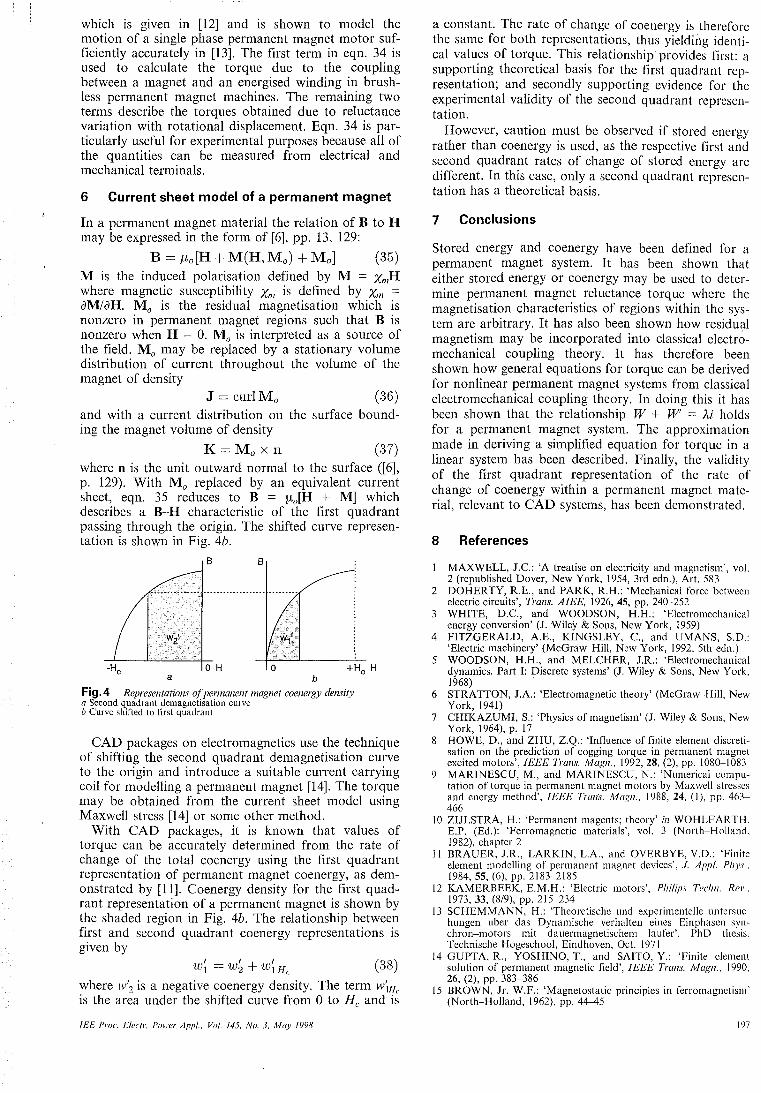
which is given in [12] and is shown to model the motion of a single phase permanent magnet motor sufficiently accurately in [13]. The first term in eqn. 34 is used to calculate the torque due to the coupling between a magnet and an energised winding in brushless permanent magnet machines. The remaining two terms describe the torques obtained due to reluctance variation with rotational displacement. Eqn. 34 is particularly useful for experimental purposes because all of the quantities can be measured from electrical and mechanical terminals.
6 Current sheet model of a permanent magnet
In a permanent magnet material the relation of B to H may be expressed in the form of [6], pp. 13, 129:
B = fLo[H + M(H, Mo) + Mol (35) M is the induced polarisation defined by M = XII1H where magnetic susceptibility XI11 is defined by XII1 aMlaH. Mo is the residual magnetisation which is nonzero in permanent magnet regions such that B is nonzero when H = O. Mo is interpreted as a source of the field. Mo may be replaced by a stationary volume distribution of current throughout the volume of the magnet of density
J = curlMo (36) and with a current distribution on the surface bounding the magnet volume of density
K = Mo x 11 (37) where n is the unit outward normal to the surface ([6], p. 129). With Mo replaced by an equivalent current sheet, eqn. 35 reduces to B = flo[H + M] which describes a B-H characteristic of the first quadrant passing through the origin. The shifted curve representation is shown in Fig. 4b.
B B
o H o a b
Fig.4 Representations a/permanent magnet coenergy density a Second quadrant demagnetisation curve b Curve shifted to first quadrant
CAD packages on electromagnetics use the technique of shifting the second quadrant demagnetisation curve to the origin and introduce a suitable current carrying coil for modelling a permanent magnet [14]. The torque may be obtained from the current sheet model using Maxwell stress [14] or some other method.
With CAD packages, it is known that values of torque can be accurately determined from the rate of change of the total co energy using the first quadrant representation of permanent magnet coenergy, as demonstrated by [11]. Coenergy density for the first quadrant representation of a permanent magnet is shown by the shaded region in Fig. 4b. The relationship between first and second quadrant co energy representations is given by
w~ = w~ + W~H, (38) where W'2 is a negative coenergy density. The term lV'lHe is the area under the shifted curve from 0 to He and is
fEE Prot.-Eleetr. Power Appl .. Vol. f45, No.3, May f991i
a constant. The rate of change of coenergy is therefore the same for both representations, thus yielding identical values of torque. This relationship provides first: a supporting theoretical basis for the first quadrant representation; and secondly supporting evidence for the experimental validity of the second quadrant representation.
However, caution must be observed if stored energy rather than co energy is used, as the respective first and second quadrant rates of change of stored energy are different. In this case, only a second quadrant representation has a theoretical basis.
7 Conclusions
Stored energy and co energy have been defined for a permanent magnet system. It has been shown that either stored energy or co energy may be used to determine permanent magnet reluctance torque where the magnetisation characteristics of regions within the system are arbitrary. It has also been shown how residual magnetism may be incorporated into classical electromechanical coupling theory. It has therefore been shown how general equations for torque can be derived for nonlinear permanent magnet systems from classical electromechanical coupling theory. In doing this it has been shown that the relationship W + W = Ai holds for a permanent magnet system. The approximation made in deriving a simplified equation for torque in a linear system has been described. Finally, the validity of the first quadrant representation of the rate of change of co energy within a permanent magnet material, relevant to CAD systems, has been demonstrated.
8 References
MAXWELL, J.C.: 'A treatise on electricity and magnetism', vol. 2 (republished Dover, New York, 1954, 3rd edn.), Art. 583
2 DOHERTY, R.E., and PARK, R.H.: 'Mechanical force between electric circuits', Trans. AlEE, 1926, 45, pp. 240-252
3 WHITE, D.C., and WOODSON, H.H.: 'Electromechanical energy conversion' (J. Wiley & Sons, New York, 1959)
4 FITZGERALD, A.E., KINGSLEY, c., and UMANS, S.D.: 'Electric machinery' (McGraw-Hili, New York, 1992, 5th edn.)
5 WOODSON, H.H., and MELCHER, l.R.: 'Electromechanical dynamics. Part I: Discrete systems' (J. Wiley & Sons, New York. 1968)
6 STRATTON, J.A.: 'Electromagnetic theory' (McGraw-Hili, New York, 1941)
7 CHIKAZUMI, S.: 'Physics of magnetism' (J. Wiley & Sons, New York, 1964), p. 17
8 HOWE, D., and ZHU, Z.Q.: 'Influence of finite element discretisation on the prediction of cogging torque in permanent magnet excited motors', IEEE Trans. Magn., 1992,28, (2), pp. 1080-1083
9 MARINESCU, M., and MARINESCU, N.: 'Numerical computation of torque in permanent magnet motors by Maxwell strcsses and energy method', IEEE Trans. Magn., 1988,24, (I), pp. 463-466
10 ZIJLSTRA, H.: 'Permanent magents; theory' in WOHLFARTH. E.P. (Ed.): 'Ferromagnetic materials', vol. 3 (North-Holland. 1982), chapter 2
II BRAUER, l.R., LARKIN, L.A., and OVERBYE, V.D.: 'Finite element modelling of permanent magnet devices', 1. Apl'f. Ph),s .. 1984,55, (6), pp. 2183-2185
12 KAMERBEEK, E.M.H.: 'Electric motors', Philips Techn. Rei'., 1973,33, (8/9), pp. 215-234
13 SCHEMMANN, H.: 'Theoretische und experimentelle untersuchungen uber das Dynamische verhalten eines Einphascn-synchron-motors mit dauermagnetischem laufer'. PhD thesis. Technische Hogeschool, Eindhoven, Oct. 1971
14 GUPTA, R., YOSHINO, T., and SAITO, Y.: 'Finite clement solution of permanent magnetic field', IEEE Trans. Magll .. 1990. 26, (2), pp. 383-386
15 BROWN, lr. W.F.: 'Magnetostatic principles in ferromagnctism' (North-Holland, 1962), pp. 44-45
In
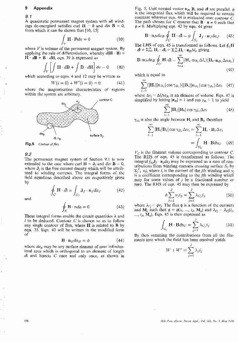
9 Appendix
9.1 A quasistatic permanent magnet system with all windings de-energised satisfies curl H = 0 and div B = 0, from which it can be shown that [10, 15]
fv H . Bdv = 0 (39)
where V is volume of the permanent magnet system. By applying the rule of differentiation, whereby d(H . B) = H . dB + B . dR, eqn. 39 is expressed as
fv [J H· dB + J B . dH] dv = 0 (40)
which according to eqns. 4 and 12 may be written as
Wei = 0) + W'(i = 0) = 0 (41)
where the magnetisation characteristics of regions within the system are arbitrary.
dl, nB
Fig.5 Contour afflux
9.2
surface SJ
The permanent magnet system of Section 9.1 is now extended to the case where curl H = Jj and div B = 0, where Jj is the free current density which will be attributed to winding currents. The integral forms of the field equations described above are respectively given by
and
Is B ·nda=O (43)
These integral forms enable the circuit quantities A and i to be deduced. Contour C is chosen so as to follow any single contour of flux, where H is related to B by eqn. 35. Eqn. 43 will be written in the modified form of
(44)
where daB may be any surface element of near infinitesimal area which is orthogonal to an element of length dI and bisects C once and only once, as shown in
198
Fig. 5. Unit normal vector DB, B, and dI are parallel. ¢ is the integrated flux which will be required to remain constant wherever eqn. 44 is evaluated over contour C. The path chosen for C ensures that B . n ¢ 0 such that ¢ ¢ O. Multiplying eqn. 42 by eqn. 44 gives
B'l1BdaB l H·dl=<!> r Jf'l1JdaJ (45) fc JSJ
The LHS of eqn. 45 is transformed as follows. Let PcH . dI = Li:l Hi' d1i = Li:lHi . DB,AI;, giving
B·nBdaB fa H·dl = ~(Hi.nBi.6.li)(Bi'l1B;.6.aBJ (46)
which is equal to 00
2:)IHilll1B; I cos'/'H;)(IBillnBi I COS'/'BJ.6.Vi (47) i=l
where 6.V· = M/·6.aB· is an element of volume. Eqn. 47 is /, .
simplified by letting IDBil = I and cos rBi = 1 to Yield 00
L IHiliBil cos '/'Hi .6.Vi (48) i=l
YH; is also the angle between Hi and Bi , therefore 00 00
L IH;!B;j COS'/'H;.6.Vi = L Hi' Bi.6.Vi i=1 i=l
= r H· Bdvc (49) JVa
V c is the filament volume corresponding to contour C. The RHS of eqn. 45 is transformed as follows. The integral JS~j' DJdaJ may be expressed as a sum of contributions from winding currents crossing surface SJ by L ~1 Y·i- where ij is the current of the Jth winding and 'j ii a c6~fficient corresponding to the Jth winding which may for some values of J be a fractional number or zero. The RHS of eqn. 45 may then be expressed by
J J
<!> L l/jij = L ACjij (50) j=l j=l
where AC' = ¢Yjo The flux <j> is a function of the currents and Mo ~uch that <P = <PCib ... , i;, Mo) and Aq = Ac/ib ... , iJ, Mo). Eqn. 45 is then expressed as
J f H· Bdvc = L ACjij (51) Va j=l
By then summing the contributions from all the filaments into which the field has been resolved yields
J
W+W'= LAjij j=l
lEE Prot.-Eleelr. Power Apl'l .• Vol. 145. No.3. May N98
1
Effects of Airgap and Magnet Shapes on Permanent Magnet Reluctance Torque
R. J. STRAHAN, and D. B. WATSON
Abstract
This paper examines the permanent magnet reluctance torques produced by three different configurations of permanent magnet, airgap, and iron. These configurations are briefly described here as rectangular magnet/triangular airgap, rectangular magnet/sinusoidal airgap, and sinusoidal magnet/sinusoidal airgap. The analysis of the torques is achieved by developing analytical solutions. Equations for magnet reluctance torque are obtained by finding the derivative of the stored field energy with respect to position. The triangular airgap configuration is shown to produce a torque waveform which approximates a triangular waveform, and both the sinusoidal airgap configurations are shown to produce torque waveforms which approximate sinusoids.
1. INTRODUCTION
This paper examines the torques produced by three different configurations of permanent magnet, airgap, and iron. These configurations are briefly described here as rectangular magnet/triangular airgap, rectangular magnet/sinusoidal airgap, and sinusoidal magnet/sinusoidal airgap. The analysis of the torque is achieved by development of analytical solutions. The advantages of the analytical approach over numerical approaches, such as finite elements, are that the former affords greater insight into the influence of design parameters, and imposes less of a computational burden. Equations for magnet reluctance torque are obtained analytically from the derivative of the stored field energy with respect to position. The stored field energy is obtained with the use of an elementary expression for the magnetic field. The approach taken to obtain the torque contrasts with that of integration of the tangential Maxwell stress along an arc in the airgap, in that the latter requires accurately determined values for the tangential and normal flux density components.
II. BASIS OF ANALYSIS
A. Reluctance Torque and Stored Field Energy
For a quasi-static electromagnetic device, energy may be stored by the magnetic field. The magnetic field energy is supplied by mechanical and electrical sources [1]. If there are no electrical sources, energy is transferred only between the magnetic field and the mechanical source. In this case, for a rotational displacement (Jr, the resulting reluctance torque is defined as the negative rate of conversion of stored energy into mechanical energy:
(1)
In the configurations listed above, the magnetic field permeates air, iron, and permanent magnet regions. The stored field energy is obtained by summing the energies of the three regions:
W = Wair + Wiron + Wpm (2)
The authors wish to express their gratitude to Dr J. D. Edwards ofthe University of Sussex for performing the finite element analysis in this paper.
R. J. Strahan and D. B. Watson are with the Department of Electrical & Electronic Engineering, University of Canterbury, Christchurch, New Zealand.
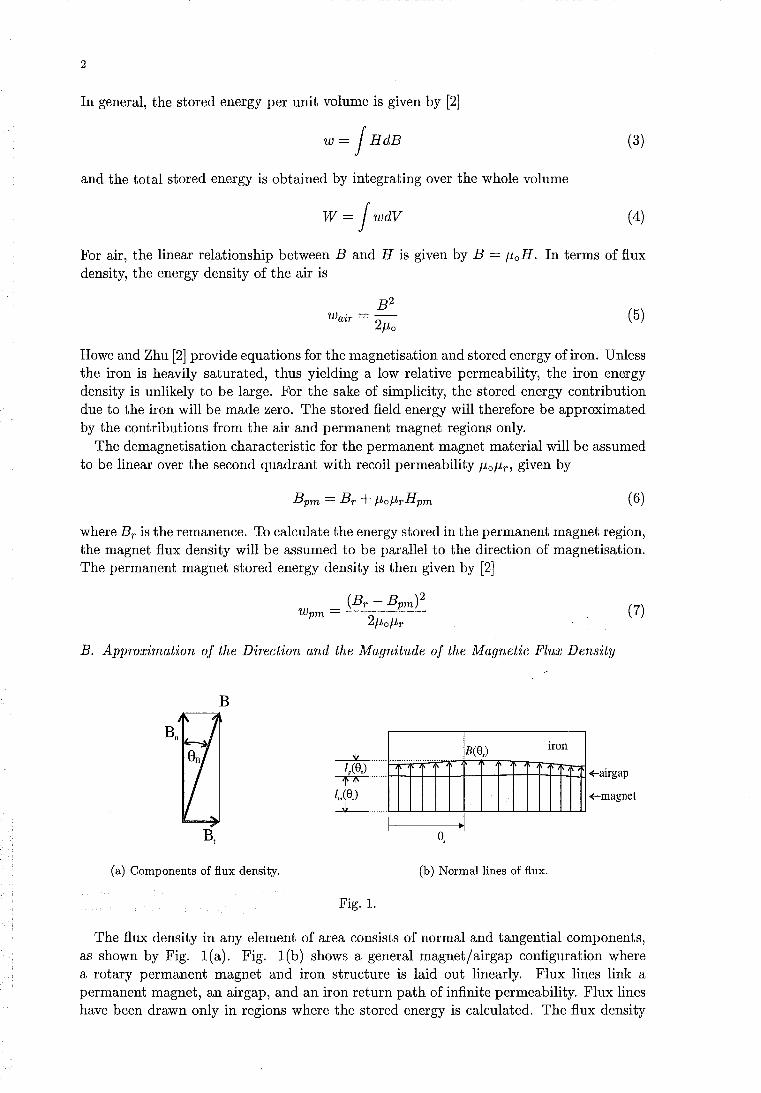
2
In general, the stored energy per unit volume is given by [2]
W = J HdB (3)
and the total stored energy is obtained by integrating over the whole volume
W=JWdV (4)
For air, the linear relationship between Band H is given by B = /-loH. In terms of flux density, the energy density of the air is
(5)
Howe and Zhu [2] provide equations for the magnetisation and stored energy of iron. Unless the iron is heavily saturated, thus yielding a low relative permeability, the iron energy density is unlikely to be large. For the sake of simplicity, the stored energy contribution due to the iron will be made zero. The stored field energy will therefore be approximated by the contributions from the air and permanent magnet regions only.
The demagnetisation characteristic for the permanent magnet material will be assumed to be linear over the second quadrant with recoil permeability /-lo/-lr, given by
(6)
where Br is the remanence. To calculate the energy stored in the permanent magnet region, the magnet flux density will be assumed to be parallel to the direction of magnetisation. The permanent magnet stored energy density is then given by [2]
(7)
B. Approximation of the Direction and the Magnitude of the Magnetic Flux Density
B
(a) Components of flux density.
Fig. 1.
! i iE(S,)
~I S,
(b) Normal lines of flux.
iron
+-airgap
+--magnet
The flux density in any element of area consists of normal and tangential components, as shown by Fig. 1(a). Fig. 1(b) shows a general magnet/airgap configuration where a rotary permanent magnet and iron structure is laid out linearly. Flux lines link a permanent magnet, an airgap, and an iron return path of infinite permeability. Flux lines have been drawn only in regions where the stored energy is calculated. The flux density
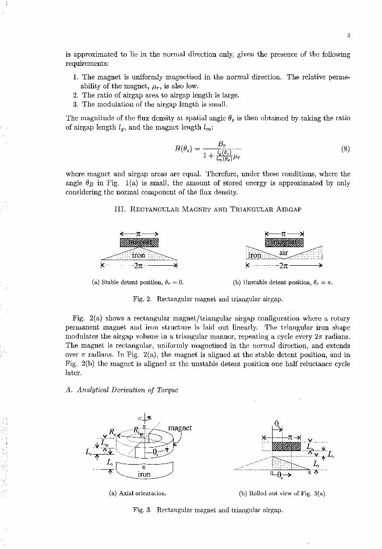
3
is approximated to lie in the normal direction only, given the presence of the following requirements:
1. The magnet is uniformly magnetised in the normal direction. The relative permeability of the magnet, /-Lr, is also low.
2. The ratio of airgap area to airgap length is large. 3. The modulation of the airgap length is small.
The magnitude of the flux density at spatial angle Bs is then obtained by taking the ratio of airgap length 19, and the magnet length lm:
(8)
where magnet and airgap areas are equal. Therefore, under these conditions, where the angle BE in Fig. l(a) is small, the amount of stored energy is approximated by only considering the normal component of the flux density.
III. REOTANGULAR MAGNET AND TRIANGULAR AIRGAP
1< >1
(a) Stable detent position, Or = O. (b) Unstable detent position, Or = 1r.
Fig. 2. Rectangular magnet and triangular airgap.
Fig. 2(a) shows a rectangular magnet/triangular airgap configuration where a rotary permanent magnet and iron structure is laid out linearly. The triangular iron shape modulates the airgap volume in a triangular manner, repeating a cycle every 21l" radians. The magnet is rectangular, uniformly magnetised in the normal direction, and extends over 1l" radians. In Fig. 2(a), the magnet is aligned at the stable detent position, and in Fig. 2(b) the magnet is aligned at the unstable detent position one half reluctance cycle later.
A. Analytical Derivation of Torque
IE-+--+--n~ ..... ~ .......... ..
::::~~:~:::;:Lc Lt
4 ••• :· ••••••••••••••••••••••••••• i-c:'--!--'-~1t .. il\ ....... .
(a) Axial orientation. (b) Rolled out view of Fig. 3(a).
Fig. 3. Rectangular magnet and triangular airgap.
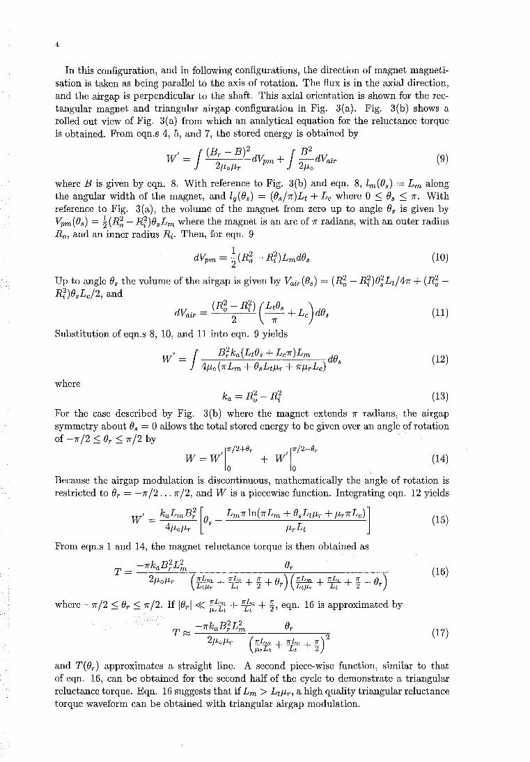
4
In this configuration, and in following configurations, the direction of magnet magnetisat ion is taken as being parallel to the axis of rotation. The flux is in the axial direction, and the air gap is perpendicular to the shaft. This axial orientation is shown for the rectangular magnet and triangular airgap configuration in Fig. 3(a). Fig. 3(b) shows a rolled out view of Fig. 3(a) from which an analytical equation for the reluctance torque is obtained. From eqn.s 4, 5, and 7, the stored energy is obtained by
I J (Br - B)2 J B2 W = dvpm + -dVair 2~o~r 2~o
(9)
where B is given by eqn. 8. With reference to Fig. 3(b) and eqn. 8, lm(Os) = Lm along the angular width of the magnet, and 19(Os) = (Os/1f)Lt + Lc where 0 ~ Os ~ 1f. With reference to Fig. 3(a), the volume of the magnet from zero up to angle Os is given by VPm(Os) = ~(R~ - Rr)esLm where the magnet is an arc of 1f radians, with an outer radius Ro, and an inner radius Ri. Then, for eqn. 9
(10)
Up to angle Os the volume of the airgap is given by Vair(Os) = (R~ - Rr)e;Lt/41f + (R~ -Rr)esLc/2, and
dV. - (R~ - Rr) (LtOs L )dO a2r - 2 1f + c s (11)
Substitution of eqn.s 8, 10, and 11 into eqn. 9 yields
Wi = J B;ka(LtOs + Lc1f)Lm dOs 4~o(1fLm + OsLt~r + 1f~rLc) (12)
where ka = R~ - Rr (13)
For the case described by Fig. 3(b) where the magnet extends 1f radians, the airgap symmetry about Os = 0 allows the total stored energy to be given over an angle of rotation of -1f/2 ~ Or ~ 1f/2 by
1
71' /2+()r 171' /2-()r W=W' + Wi
o 0 (14)
Because the airgap modulation is discontinuous, mathematically the angle of rotation is restricted to Or = -1f /2 ... 7r /2, and W is a piecewise function. Integrating eqn. 12 yields
Wi = kaLmB; [Os _ Lm7rln(7rLm + OsLt~r + ~r7rLc)l (15) 4~o~r ~rLt
From eqn.s 1 and 14, the magnet reluctance torque is then obtained as
T = -7rkaB;L~ Or (16) 2~o~r (7I'Lm + 'lIb. + 1!: + 0 ) (7I'Lm + 'lIb. + 1!: - 0 )
Lt/-Lr Lt 2 r Lt/-Lr Lt 2 r
where -7r/2 ~ Or ~ 1f/2. If IOrl « ~~lt + ¥: +~, eqn. 16 is approximated by
T ~ -7rkaB;L~ Or
2~o~r (7I'Lm + 'lIb. + 1!:)2 /-LrLt Lt 2
(17)
and T( Or) approximates a straight line. A second piece-wise function, similar to that of eqn. 16, can be obtained for the second half of the cycle to demonstrate a triangular reluctance torque. Eqn. 16 suggests that if Lm > Lt~r, a high quality triangular reluctance torque waveform can be obtained with triangular airgap modulation.
magnet
iron flux guide
airgap
iron plate
5
Fig. 4. Finite element flux plot, 3rd order solution. Magnet thickness Lm = 5 mm, maximum triangular airgap modulation length Lt = 1 mm, un-modulated airgap clearance Lc = 0.5 mm, Br = 0.68 T, magnet relative recoil permeability f-1r = 1.25.
B. Finite Element and Experimental Results
The following results are obtained for another configuration where the airgap is also modulated triangularly. However, these results are not directly applicable to the configuration described by Fig. 3. Fig. 4 shows a finite element flux plot for a linear configuration, from top to bottom, consisting of a permanent magnet, iron flux guide, airgap, and triangularly modulated iron plate. The iron flux guide and the magnet are attached together. The triangular modulation on the iron plate completes a reluctance cycle. The magnet is rectangular and extends for nearly a full reluctance cycle. The lower portion of the iron flux guide extends for half a reluctance cycle. The magnet is magnetised in the normal direction (up the page), and is modelled as a linear material specified by its remanence and recoil permeability. The iron regions are represented by the magnetisation curve of a silicon sheet steel. Half periodic boundary conditions are specified at the left and right sides of the model.
The magnet and iron flux guide are shown at a position corresponding to Or = 31f /2 where the reluctance torque is at its peak magnitude. A tangential force on the magnet and flux guide pulls the two components to the right. A derivation of an analytical force solution for this more complex configuration has not been attempted; The linear two dimensional model of Fig. 4 was designed to represent an experimental axial device. For the experimental device, a radius at which the tangential force acted was assumed to lie where the magnet surface areas inside and outside the radius were equal. This enabled an equivalent linear model magnet length to be calculated. An equivalent magnet width was then selected such that the magnet surface areas of the linear model and those of the experimental device were the same. The heights of linear model and of experimental device components remained identical. The value of the radius at which the tangential force acted could then be used to convert linear model forces into torques.
Table I presents torques, obtained from finite element analysis forces, at four selected positions over the reluctance torque cycle. The correct values of the reluctance torque at angles Or = 0 and Or = 1f are zero, and the non-zero values at these positions give an indication of the magnitude of the finite element error. The number of positions plotted still do not present a detailed picture of the waveform shape. Figure 5 presents an experimental plot of the reluctance torque corresponding to Or = 0 ... 1f. The solid line drawn over the measured points shows that a triangular waveform shape is clearly discernible, with a rounded curve at Or = 1f /2. Unfortunately, the magnitudes of the experimental reluctance torque points cannot be compared to those in Table 1. This is because the grade of stainless steel used to support the magnet and iron flux guide was discovered to have a small but significant relative permeability of approximately three. This caused more flux to be shunted away from the triangular airgap which reduced the amplitude of the reluctance torque. This effect was not modelled in the finite element analysis to allow comparison.
6
Reluctance angle Torque On (rad.) (Nm)
0 0.019 1f/2 -0.596
1f 0.009 31f/2 0.604
TABLE I RELUOTANOE TORQUES OORRESPONDING TO THE OONFIGURATION OF FIG. 4.
-0.05
-0.1
8-0.15
e-o -0.2
6< I-<
~ -0.25
-0.3
-0.35
-0.4 '--~--'-~~--'-~~--L-~~"----~--'-~~~ o 0.5 1 1.5 2 2.5
Angle (reluctance rad.)
Fig. 5. Experimental measurement of the magnet reluctance torque corresponding to the configuration of Fig. 4.
IV. RECTANGULAR MAGNET AND SINUSOIDAL AIRGAP
A. Axial Magnetisation
Fig. 6. Rectangular magnet and sinusoidal airgap.
Fig. 6 shows a rolled out view of an axially magnetised permanent magnet and iron structure. The magnet is rectangular and the airgap is sinusoidal. The three dimensional depiction of this axial configuration is similar to that of Fig. 3(a), except that the airgap is modulated sinusoidally for this example. The magnet is uniformly magnetised in the normal (axial) direction, and extends between angles 01 and O2 . The use of variables (h and (h allows the magnet width to be arbitrarily adjusted, under the constraint that o :::; O2 - (h :::; 21f. Again, only the normal flux paths through the magnet, and in the airgap underneath the magnet, are considered. The stored energy is obtained by integration of
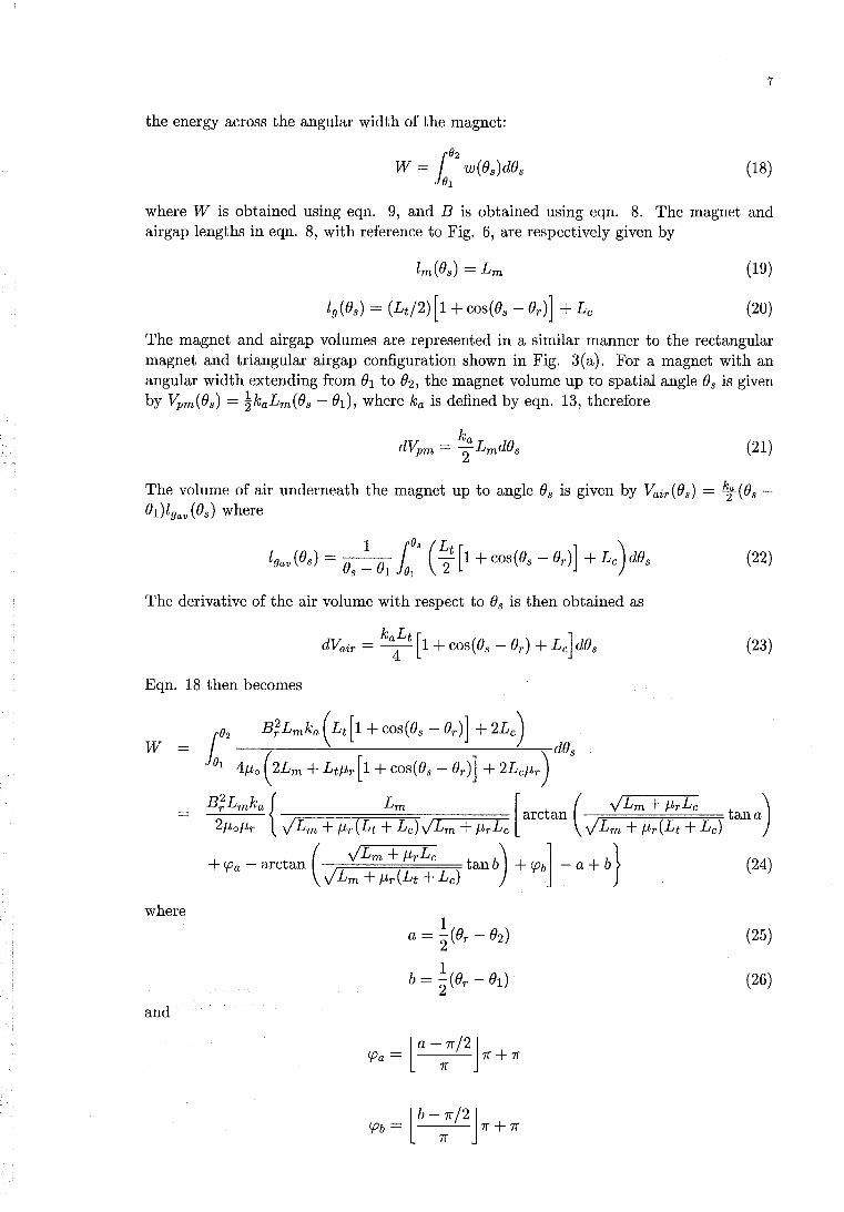
7
the energy across the angular width of the magnet:
(18)
where W is obtained using eqn. 9, and B is obtained using eqn. 8. The magnet and airgap lengths in eqn. 8, with reference to Fig. 6, are respectively given by
(19)
(20)
The magnet and air gap volumes are represented in a similar manner to the rectangular magnet and triangular airgap configuration shown in Fig. 3(a). For a magnet with an angular width extending from (h to (h the magnet volume up to spatial angle Os is given by Vpm(Os) = !kaLm(Os - ( 1), where ka is defined by eqn. 13, therefore
(21)
The volume of air underneath the magnet up to angle Os is given by Vair(Os) = ~(Os -Ol)lgav(Os) where
(22)
The derivative of the air volume with respect to Os is then obtained as
(23)
Eqn. 18 then becomes
W
where
(25)
(26)
and
la-7r/2J CPa = 7r 7r + 7r
lb-7r/2J CPb = 7r 7r + 7r
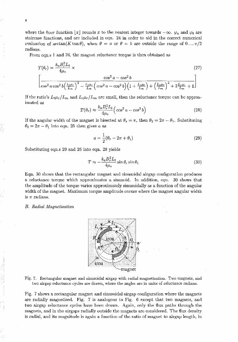
8
where the floor function l x J rounds x to the nearest integer towards -00. CPa and CPb are staircase functions, and are included in eqn. 24 in order to aid in the correct numerical evaluation of arctan(KtanO), when 0 = a or 0 = b are outside the range of 0 ... 7r/2 radians.
From eqn.s 1 and 24, the magnet reluctance torque is then obtained as
If the ratio's Ltf-trl Lm and Lcf-trl Lm are small, then the reluctance torque can be approximated as
(28)
If the angular width of the magnet is bisected at Os = 7r, then O2 = 27r - 01 . Substituting O2 = 27r - 01 into eqn. 25 then gives a as
(29)
Substituting eqn.s 29 and 26 into eqn. 28 yields
T kaB;Lt . II • II
~ - Slnur SlnU1 4f-to
(30)
Eqn. 30 shows that the rectangular magnet and sinusoidal airgap configuration produces a reluctance torque which approximates a sinusoid. In addition, eqn. 30 shows that the amplitude of the torque varies approximately sinusoidally as a function of the angular width of the magnet. Maximum torque amplitude occurs where the magnet angular width is 7r radians.
B. Radial Magnetisation
magnet
Fig. 7. Rectangular magnet and sinusoidal airgap with radial magnetisation. Two magnets, and two airgap reluctance cycles are drawn, where the angles are in units of reluctance radians.
Fig. 7 shows a rectangular magnet and sinusoidal airgap configuration where the magnets are radially magnetised. Fig. 7 is analogous to Fig. 6 except that two magnets, and two airgap reluctance cycles have been drawn. Again, only the flux paths through the magnets, and in the airgaps radially outside the magnets are considered. The flux density is radial, and its magnitude is again a function of the ratio of magnet to airgap length, in
9
this case along a radial path. The equations used to construct the stored energy integral are identical to the axial magnetisation example of section IV-A, except that the airgap and magnet volumes are obtained by integrating over cylindrical coordinates. The magnet and airgap volumes can be obtained respectively from
(31)
(32)
where Ha is the axial height of the magnet and airgap, all angles are in units of reluctance radians, and the integrations are performed over only a single airgap reluctance cycle. If the angular width of the magnet is bisected at Os = 7r, then O2 = 27r - 01, and the torque is given by
where A
B
c
D
u v =
cos t(Or - 01 )
cos '2 (Or + 01)
T = qHaB;(A + B) 4/-Lo(C + D)
(33)
and q is the number of airgap reluctance cycles per mechanical cycle. If Lc = 0, then B = D = O. If the ratio Lt/-Lr / Lm is assumed to be negligible, then C = 1. If the ratio's Lt/ Lm, Lr / Lm, and Lr / L~ are assumed to be negligible, term A is also simplified. If these assumptions are applied, and if (h = 7r /2 such that each magnet is an arc of 7r reluctance radians, then eqn. 33 reduces to
(34)
and the magnet reluctance torque waveform approximates a sinusoid.
V. SINUSOIDAL MAGNET AND SINUSOIDAL AIRGAP
Fig. 8 shows a rolled out view of an axially magnetised permanent magnet and iron structure where both the magnet and the airgap have sinusoidal shapes. The magnet is uniformly magnetised in the normal (axial) direction, and extends over a fixed angular
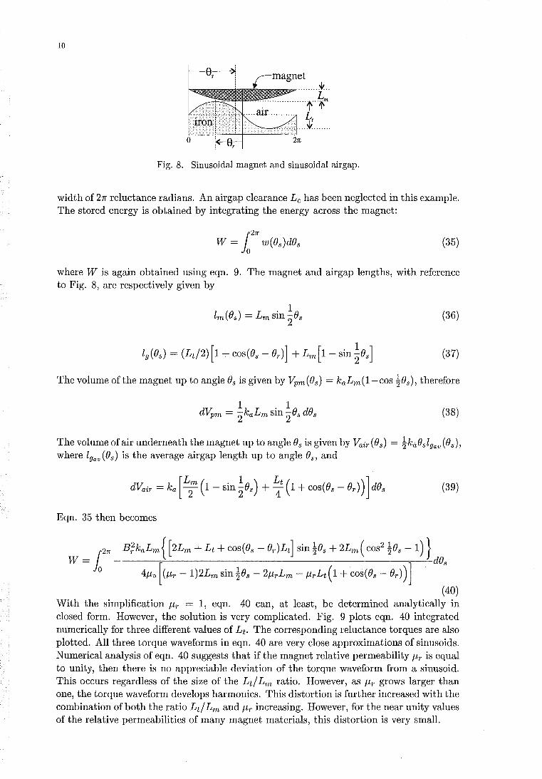
10
Fig. 8. Sinusoidal magnet and sinusoidal airgap.
width of 21T reluctance radians. An air gap clearance Lc has been neglected in this example. The stored energy is obtained by integrating the energy across the magnet:
(35)
where W is again obtained using eqn. 9. The magnet and airgap lengths, with reference to Fig. 8, are respectively given by
(36)
(37)
The volume of the magnet up to angle Os is given by Vpm(Os) = kaLm(1-cos ~Os), therefore
(38)
The volume of air underneath the magnet up to angle Os is givenby Vair(Os) = ~kaOslgav (Os), where 19av (Os) is the average airgap length up to angle Os, and
dVair = ka [L2m (1 - sin ~Os) + ~t (1 + cos (Os - Or)) ] dOs (39)
Eqn. 35 then becomes
_ r27r B;kaLm {[ 2Lm + Lt + cos(Os - Or )Lt] sin ~Os + 2Lm ( cos2 ~Os - 1) } W - io - [ ] dOs
o 4f-lo (f-lr -1)2Lm sin ~Os - 2f-lrLm - f-lrLt( 1 + cos(Os - Or))
(40) With the simplification f-lr = 1, eqn. 40 can, at least, be determined analytically in closed form. However, the solution is very complicated. Fig. 9 plots eqn. 40 integrated numerically for three different values of Lt. The corresponding reluctance torques are also plotted. All three torque waveforms in eqn. 40 are very close approximations of sinusoids. Numerical analysis of eqn. 40 suggests that if the magnet relative permeability f-lr is equal to unity, then there is no appreciable deviation of the torque waveform from a sinusoid. This occurs regardless of the size of the Lt! Lm ratio. However, as f-lr grows larger than one, the torque waveform develops harmonics. This distortion is further increased with the combination of both the ratio Lt! Lm and f-lr increasing. However, for the near unity values of the relative permeabilities of many magnet materials, this distortion is very small.
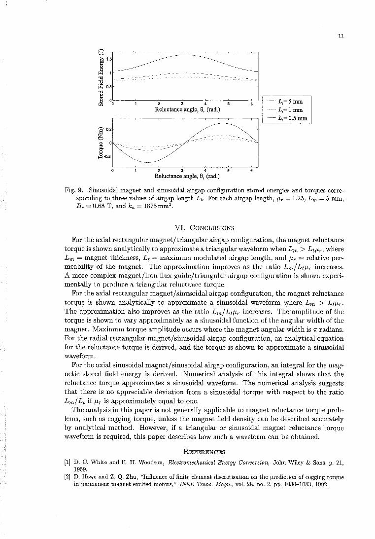
s ~ 1.5
~ &l 1
~ ~ 0.5
1 ~L-----~----~2----~3----~4----~5------6~ Reluctance angle, a, (rad.)
E 0.2
b <I) 0 .~.
6< .... ~-0.2
o 2 3 4 5 6 Reluctance angle, a, (rad.)
11
-L,=5mm ----. L, = 1 mm ....... L,= 0.5 mm
Fig. 9. Sinusoidal magnet and sinusoidal airgap configuration stored energies and torques corresponding to three values of airgap length Lt. For each airgap length, J.Lr = 1.25, Lm = 5 mm, Br = 0.68 T, and ka = 1875 mm2 •
VI. CONCLUSIONS
For the axial rectangular magnet/triangular airgap configuration, the magnet reluctance torque is shown analytically to approximate a triangular waveform when Lm > LtJ.Lr, where Lm = magnet thickness, Lt = maximum modulated airgap length, and J.Lr = relative permeability of the magnet. The approximation improves as the ratio Lm/ LtJ.Lr increases. A more complex magnet/iron flux guide/triangular airgap configuration is shown experimentally to produce a triangular reluctance torque.
For the axial rectangular magnet/sinusoidal airgap configuration, the magnet reluctance torque is shown analytically to approximate a sinusoidal waveform. where Lm > Ltf-tr. The approximation also improves as the ratio Lm/ LtJ.Lr increases. The amplitude of the torque is shown to vary approximately as a sinusoidal function of the angular width of the magnet. Maximum torque amplitude occurs where the magnet angular width is 7f radians. For the radial rectangular magnet/sinusoidal airgap configuration, an analytical equation for the reluctance torque is derived, and the torque is shown to approximate a sinusoidal waveform.
For the axial sinusoidal magnet/sinusoidal airgap configuration, an integral for the magnetic stored field energy is derived. Numerical analysis of this integral shows that the reluctance torque approximates a sinusoidal waveform. The numerical analysis suggests that there is no appreciable deviation from a sinusoidal torque with respect to the ratio Lm/ Lt if f-tr is approximately equal to one.
The analysis in this paper is not generally applicable to magnet reluctance torque problems, such as cogging torque, unless the magnet field density can be described accurately by analytical method. However, if a triangular or sinusoidal magnet reluctance torque waveform is required, this paper describes how such a waveform can be obtained.
REFERENCES
[1) D. C. White and H. H. Woodson, Electromechanical Energy Conversion, John Wiley & Sons, p. 21, 1959.
[2) D. Howe and Z. Q. Zhu, "Influence of finite element discretisation on the prediction of cogging torque in permanent magnet excited motors," IEEE Trans. Magn., vol. 28, no. 2, pp. 1080-1083, 1992.
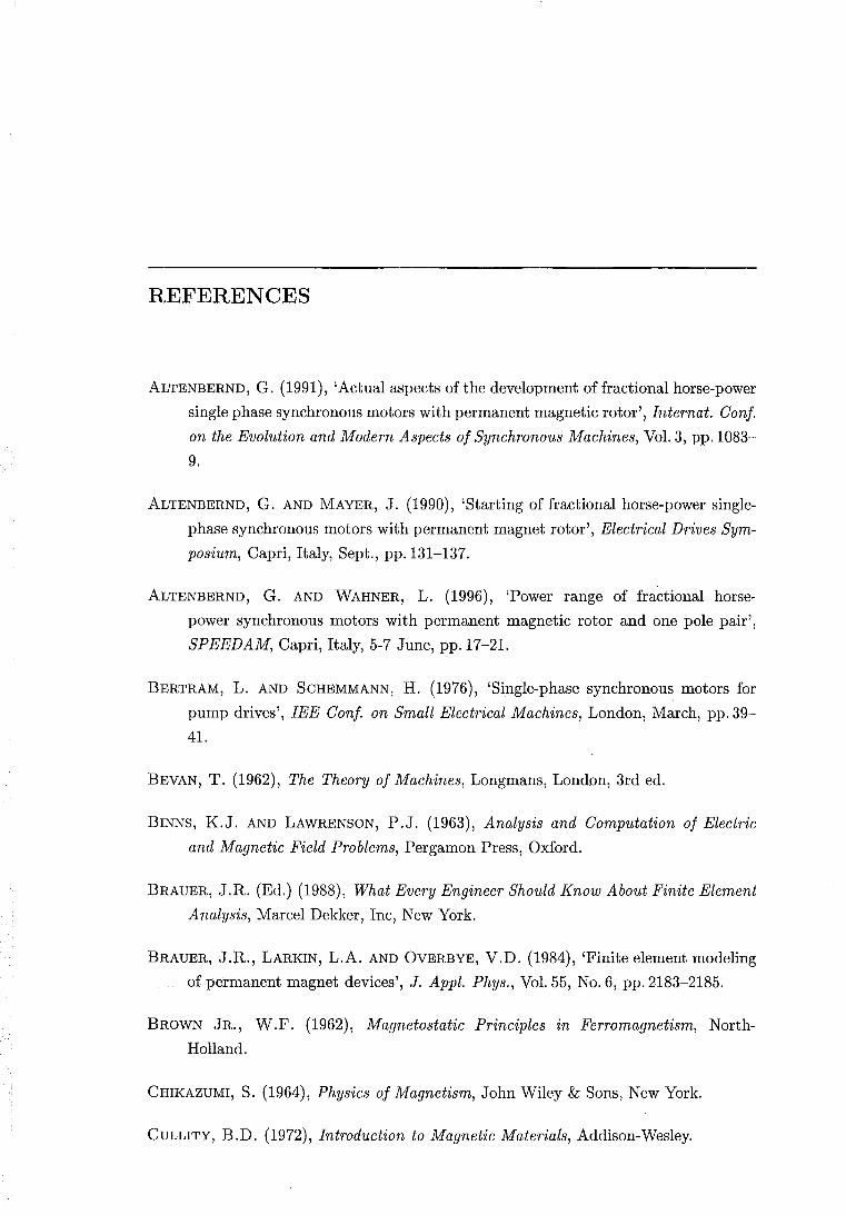
REFERENCES
ALTENBERND, G. (1991), 'Actual aspects ofthe development offractional horse-power
single phase synchronous motors with permanent magnetic rotor', Internat. Conf.
on the Evolution and Modern Aspects of Synchronous Machines, Vol. 3, pp.1083-
9.
ALTENBERND, G. AND MAYER, J. (1990), 'Starting of fractional horse-power single
phase synchronous motors with permanent magnet rotor', Electrical Drives Sym
posium, Capri, Italy, Sept., pp.131-137.
ALTENBERND, G. AND WAHNER, L. (1996), 'Power range of fractional horse
power synchronous motors with permanent magnetic rotor and one pole pair',
SPEEDAM, Capri, Italy, 5-7 June, pp.17-21.
BERTRAM, L. AND SCHEMMANN, H. (1976), 'Single-phase synchronous motors for
pump drives', lEE Conf. on Small Electrical Machines, London, March, pp.39-
41.
BEVAN, T. (1962), The Theory of Machines, Longmans, London, 3rd ed.
BINNS, K.J. AND LAWRENSON, P .J. (1963), Analysis and Computation of Electric
and Magnetic Field Problems, Pergamon Press, Oxford.
BRAUER, J.R. (Ed.) (1988), What Every Engineer Should Know About Finite Element
Analysis, Marcel Dekker, Inc, New York.
BRAUER, J.R., LARKIN, L.A. AND OVERBYE, V.D. (1984), 'Finite element modeling
of permanent magnet devices', J. Appl. Phys., Vol. 55, No.6, pp.2183-2185.
BROWN JR., W.F. (1962), Magnetostatic Principles in Ferromagnetism, North
Holland.
CHIKAZUMI, S. (1964), Physics of Magnetism, John Wiley & Sons, New York.
CULLITY, B.D. (1972), Introduction to Magnetic Materials, Addison-Wesley.
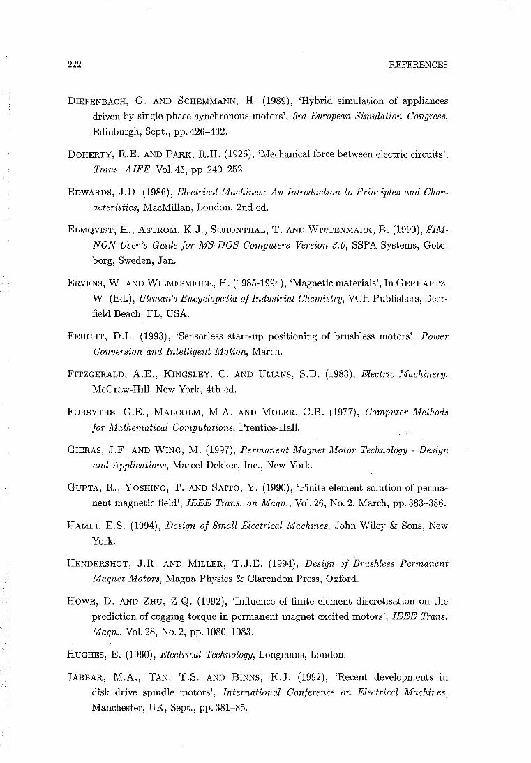
222 REFERENCES
DIEFENBACH, G. AND SCHEMMANN, H. (1989), 'Hybrid simulation of appliances
driven by single phase synchronous motors', 3rd European Simulation Congress,
Edinburgh, Sept., pp.426-432.
DOHERTY, R.E. AND PARK, R.H. (1926), 'Mechanical force between electric circuits',
Trans. AlEE, Vol. 45, pp. 240-252.
EDWARDS, J.D. (1986), Electrical Machines: An Introduction to Principles and Char
acteristics, MacMillan, London, 2nd ed.
ELMQVIST, H., ASTROM, K.J., SCHONTHAL, T. AND WITTENMARK, B. (1990), SIM
NON User's Guide for MS-DOS Computers Version 3.0, SSPA Systems, Gote
borg, Sweden, Jan.
ERVENS, W. AND WILMESMEIER, H. (1985-1994), 'Magnetic materials', In GERHARTZ,
W. (Ed.), Ullman's Encyclopedia of Industrial Chemistry, VCH Publishers, Deer
field Beach, FL, USA.
FEUCHT, D.L. (1993), 'Sensorless start-up positioning of brushless motors', Power
Conversion and Intelligent Motion, March.
FITZGERALD, A.E., KINGSLEY, C. AND UMANS, S.D. (1983), Electric Machinery,
McGraw-Hill, New York, 4th ed.
FORSYTHE, G.E., MALCOLM, M.A. AND MOLER, C.B. (1977), Computer Methods
for Mathematical Computations, Prentice-Hall.
GIERAS, J.F. AND WING, M. (1997), Permanent Magnet Motor Technology - Design
and Applications, Marcel Dekker, Inc., New York.
GUPTA, R., YOSHINO, T. AND SAITO, Y. (1990), 'Finite element solution of perma
nent magnetic field', IEEE Trans. on Magn., Vol. 26, No.2, March, pp.383-386.
HAMDI, E.S. (1994), Design of Small Electrical Machines, John Wiley & Sons, New
York.
HENDERSHOT, J.R. AND MILLER, T.J.E. (1994), Design of Brushless Permanent
Magnet Motors, Magna Physics & Clarendon Press, Oxford.
HOWE, D. AND ZHU, Z.Q. (1992), 'Influence of finite element discretisation on the
prediction of cogging torque in permanent magnet excited motors', IEEE Trans.
Magn., Vol. 28, No.2, pp.1080-1083.
HUGHES, E. (1960), Electrical Technology, Longmans, London.
JABBAR, M.A., TAN, T.S. AND BINNS, K.J. (1992), 'Recent developments in
disk drive spindle motors', International Conference on Electrical Machines,
Manchester, UK, Sept., pp.381-85.
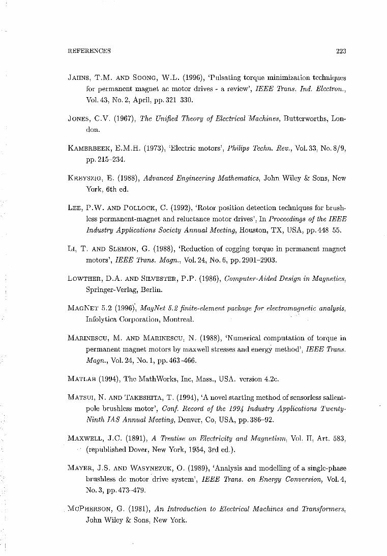
REFERENCES 223
JAHNS, T.M. AND SOONG, W.L. (1996), 'Pulsating torque minimization techniques
for permanent magnet ac motor drives - a review', IEEE Trans. Ind. Electron.,
Vol. 43, No.2, April, pp. 321-330.
JONES, C.V. (1967), The Unified Theory of Electrical Machines, Butterworths, Lon
don.
KAMERBEEK, E.M.H. (1973), 'Electric motors', Philips Techn. Rev., Vol. 33, No. 8/9,
pp. 215-234.
KREYSZIG, E. (1988), Advanced Engineering Mathematics, John Wiley & Sons, New
York, 6th ed.
LEE, P.W. AND POLLOCK, C. (1992), 'Rotor position detection techniques for brush
less permanent-magnet and reh,lctance motor drives', In Proceedings of the IEEE
Industry Applications Society Annual Meeting, Houston, TX, USA, pp.448-55.
LI, T. AND SLEMON, G. (1988), 'Reduction of cogging torque in permanent magnet
motors', IEEE Trans. Magn., Vol. 24, No.6, pp.2901-2903.
LOWTHER, D.A. AND SILVESTER, P.P. (1986), Computer-Aided Design in Magnetics,
Springer-Verlag, Berlin.
MAGNET 5.2 (1996)', MagNet 5.2 finite-element package for electromagnetic analysis,
Infolytica Corporation, Montreal.
MARINESCU, M. AND MARINESCU, N. (1988), 'Numerical computation of torque in
permanent magnet motors by maxwell stresses and energy method', IEEE Trans.
Magn., Vol. 24, No.1, pp.463-466.
MATLAB (1994), The MathWorks, Inc, Mass., USA. version 4.2c.
MATSUI, N. AND TAKESHITA, T. (1994), 'A novel starting method ofsensorless salient
pole brushless motor', Conf. Record of the 1994 Industry Applications Twenty
Ninth lAS Annual Meeting, Denver, Co, USA, pp.386-92.
MAXWELL, J.C. (1891), A Treatise on Electricity and Magnetism, Vol. II, Art. 583,
(republished Dover, New York, 1954, 3rd ed.).
MAYER, J.S. AND WASYNEZUK, O. (1989), 'Analysis and modelling of a single-phase
brushless dc motor drive system', IEEE Trans. on Energy Conversion, Vol. 4,
No.3, pp.473-479.
MCPHERSON, G. (1981), An Introduction to Electrical Machines and Transformers,
John Wiley & Sons, New York.
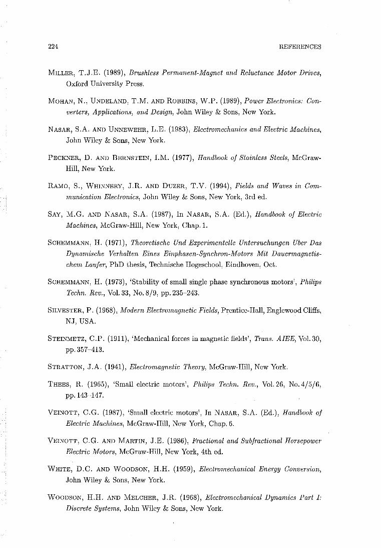
224 REFERENCES
MILLER, T.J.E. (1989), Brushless Permanent-Magnet and Reluctance Motor Drives,
Oxford University Press.
MOHAN, N., UNDELAND, T.M. AND ROBBINS, W.P. (1989), Power Electronics: Con
verters, Applications, and Design, John Wiley & Sons, New York.
NASAR, S.A. AND UNNEWEHR, L.E. (1983), Electromechanics and Electric Machines,
John Wiley & Sons, New York.
PECKNER, D. AND BERNSTEIN, I.M. (1977), Handbook of Stainless Steels, McGraw
Hill, New York.
RAMO, S., WHINNERY, J.R. AND DUZER, T.V. (1994), Fields and Waves in Com
munication Electronics, John Wiley & Sons, New York, 3rd ed.
SAY, M.G. AND NASAR, S.A. (1987), In NASAR, S.A. (Ed.), Handbook of Electric
Machines, McGraw-Hill, New York, Chap.l.
SCHEMMANN, H. (1971), Theoretische Und Experimentelle Untersuchungen Uber Das
Dynamische Verhalten Eines Einphasen-Synchron-Motors Mit Dauermagnetis
chem Laufer, PhD thesis, Technische Hogeschool, Eindhoven, Oct.
SCHEMMANN, H. (1973), 'Stability of small single phase synchronous motors', Philips
Techn. Rev., Vol. 33, No. 8/9, pp.235-243.
SILVESTER, P. (1968), Modern Electromagnetic Fields, Prentice-Hall, Englewood Cliffs,
NJ, USA.
STEINMETZ, C.P. (1911), 'Mechanical forces in magnetic fields', Trans. AlEE, Vol. 30,
pp.357-413.
STRATTON, J.A. (1941), Electromagnetic Theory, McGraw-Hill, New York.
THEES, R. (1965), 'Small electric motors', Philips Techn. Rev., Vol. 26, No. 4/5/6,
pp.143-147.
VEINOTT, C.G. (1987), 'Small electric motors', In NASAR, S.A. (Ed.), Handbook of
Electric Machines, McGraw-Hill, New York, Chap. 6.
VEINOTT, C.G. AND MARTIN, J.E. (1986), Fractional and Subfractional Horsepower
Electric Motors, McGraw-Hill, New York, 4th ed.
WHITE, D.C. AND WOODSON, H.H. (1959), Electromechanical Energy Conversion,
John Wiley & Sons, New York.
WOODSON, H.H. AND MELCHER, J.R. (1968), Electromechanical Dynamics Part I:
Discrete Systems, John Wiley & Sons, New York.
REFERENCES 225
ZIJLSTRA, H. (1982), 'Permanent magnets; theory', In WOHLFARTH, E.P. (Ed.), Fer
romagnetic Materials, North-Holland, Chap. 2.
Related Documents