Building and Environment 42 (2007) 3606–3615 Energy and exergy analysis of a ground-coupled heat pump system with two horizontal ground heat exchangers Hikmet Esen a, , Mustafa Inalli b , Mehmet Esen a , Kazim Pihtili b a Department of Mechanical Education, Faculty of Technical Education, Fırat University, 23119 Elazıg˘, Turkey b Department of Mechanical Engineering, Faculty of Engineering, Fırat University, 23119 Elazıg˘, Turkey Received 13 October 2006; received in revised form 13 October 2006; accepted 13 October 2006 Abstract In this paper we investigate of energetic and exergetic efficiencies of ground-coupled heat pump (GCHP) system as a function of depth trenches for heating season. The horizontal ground heat exchangers (HGHEs) were used and it were buried with in 1 m (HGHE1) and 2 m (HGHE2) depth trenches. The energy efficiency of GCHP systems are obtained to 2.5 and 2.8, respectively, while the exergetic efficiencies of the overall system are found to be 53.1% and 56.3%, respectively, for HGHE1 and HGHE2. The irreversibility of HGHE2 is less than of the HGHE1 as about 2.0%. The results show that the energetic and exergetic efficiencies of the system increase when increasing the heat source (ground) temperature for heating season. And the end of this study, we deal with the effects of varying reference environment temperature on the exergy efficiencies of HGHE1 and HGHE2. The results show that increasing reference environment temperature decreases the exergy efficiency in both HGHE1 and HGHE2. r 2006 Elsevier Ltd. All rights reserved. Keywords: Ground coupled heat pump; Horizontal ground heat exchanger; Energy analysis; Exergy analysis 1. Introduction The use of ground-coupled heat pumps (GCHPs) in commercial and residential facilities is a remarkable example. GCHP systems exchange heat with the ground, and maintain a high level of performance even in colder climates. This results in more efficient use of energy, for this reason many society utilities support the use of GCHP systems. The first patent on using ground as a heat source for GCHP systems, issued in Switzerland in 1992, is due to Heinrich Zoley. This date may be regarded as the official date of birth of GCHP systems, but the concept of using the ground as a heat source is much older [1]. In history, there has been a noticeable increase of interest in the applications second law analysis to the design of thermal systems [2]. A typical thermal design based on the first law thermodynamics allows us to address issues related to the energy balance of the system. The second law of thermodynamic analysis combined with a standard design procedure of a thermal system gives us invaluable insight into the operation of the system. Exergy (or availability) analysis is a powerful tool in the design, optimization and performance evaluation of energy systems. This analysis can be used to identify the main sources of irreversibility (exergy loss) and to minimize the generation of entropy in a given process where the transfer of energy and material take place [3,4]. According to Dincer and Rosen [5], exergy analysis is an effective thermodynamic scheme for using the conservation of mass and energy principles together with the second law of thermodynamic for the design and ana- lysis of thermal systems, and is an efficient technique for revealing whether or not and by how much it is possible to design more efficient thermal systems by reducing the inefficiencies. The concepts and definitions of exergy ana- lysis are well recognized [6–9]. Various theoretical [10–13] and experimental [14–18] studies based on the exergy concept with heat pump systems have been published. Nakanishi et al. [10] investigated exergetic performance of various heat pump units. Hiharat [11] has been carried out theoretically heat ARTICLE IN PRESS www.elsevier.com/locate/buildenv 0360-1323/$ - see front matter r 2006 Elsevier Ltd. All rights reserved. doi:10.1016/j.buildenv.2006.10.014 Corresponding author. Tel.: +90 424 237 0000/4228; fax: +90 424 236 7064. E-mail address: hikmetesen@firat.edu.tr (H. Esen).

Welcome message from author
This document is posted to help you gain knowledge. Please leave a comment to let me know what you think about it! Share it to your friends and learn new things together.
Transcript
ARTICLE IN PRESS
0360-1323/$ - se
doi:10.1016/j.bu
�Correspondfax: +90424 23
E-mail addr
Building and Environment 42 (2007) 3606–3615
www.elsevier.com/locate/buildenv
Energy and exergy analysis of a ground-coupled heat pump system withtwo horizontal ground heat exchangers
Hikmet Esena,�, Mustafa Inallib, Mehmet Esena, Kazim Pihtilib
aDepartment of Mechanical Education, Faculty of Technical Education, Fırat University, 23119 Elazıg, TurkeybDepartment of Mechanical Engineering, Faculty of Engineering, Fırat University, 23119 Elazıg, Turkey
Received 13 October 2006; received in revised form 13 October 2006; accepted 13 October 2006
Abstract
In this paper we investigate of energetic and exergetic efficiencies of ground-coupled heat pump (GCHP) system as a function of depth
trenches for heating season. The horizontal ground heat exchangers (HGHEs) were used and it were buried with in 1m (HGHE1) and
2m (HGHE2) depth trenches. The energy efficiency of GCHP systems are obtained to 2.5 and 2.8, respectively, while the exergetic
efficiencies of the overall system are found to be 53.1% and 56.3%, respectively, for HGHE1 and HGHE2. The irreversibility of HGHE2
is less than of the HGHE1 as about 2.0%. The results show that the energetic and exergetic efficiencies of the system increase when
increasing the heat source (ground) temperature for heating season. And the end of this study, we deal with the effects of varying
reference environment temperature on the exergy efficiencies of HGHE1 and HGHE2. The results show that increasing reference
environment temperature decreases the exergy efficiency in both HGHE1 and HGHE2.
r 2006 Elsevier Ltd. All rights reserved.
Keywords: Ground coupled heat pump; Horizontal ground heat exchanger; Energy analysis; Exergy analysis
1. Introduction
The use of ground-coupled heat pumps (GCHPs) incommercial and residential facilities is a remarkableexample. GCHP systems exchange heat with the ground,and maintain a high level of performance even in colderclimates. This results in more efficient use of energy, forthis reason many society utilities support the use of GCHPsystems. The first patent on using ground as a heat sourcefor GCHP systems, issued in Switzerland in 1992, is due toHeinrich Zoley. This date may be regarded as the officialdate of birth of GCHP systems, but the concept of usingthe ground as a heat source is much older [1].
In history, there has been a noticeable increase of interestin the applications second law analysis to the design ofthermal systems [2]. A typical thermal design based on thefirst law thermodynamics allows us to address issues relatedto the energy balance of the system. The second law of
e front matter r 2006 Elsevier Ltd. All rights reserved.
ildenv.2006.10.014
ing author. Tel.: +90424 237 0000/4228;
6 7064.
ess: [email protected] (H. Esen).
thermodynamic analysis combined with a standard designprocedure of a thermal system gives us invaluable insightinto the operation of the system. Exergy (or availability)analysis is a powerful tool in the design, optimization andperformance evaluation of energy systems. This analysiscan be used to identify the main sources of irreversibility(exergy loss) and to minimize the generation of entropy in agiven process where the transfer of energy and material takeplace [3,4]. According to Dincer and Rosen [5], exergyanalysis is an effective thermodynamic scheme for using theconservation of mass and energy principles together withthe second law of thermodynamic for the design and ana-lysis of thermal systems, and is an efficient technique forrevealing whether or not and by how much it is possible todesign more efficient thermal systems by reducing theinefficiencies. The concepts and definitions of exergy ana-lysis are well recognized [6–9].Various theoretical [10–13] and experimental [14–18]
studies based on the exergy concept with heat pumpsystems have been published. Nakanishi et al. [10]investigated exergetic performance of various heat pumpunits. Hiharat [11] has been carried out theoretically heat
ARTICLE IN PRESS
Nomenclature
COPoverall heating coefficient of performance of groundcoupled heat pump system (�)
Cp,air specific heat of air (kJ/kg K)Cp,wa specific heat of water–antifreeze solution (kJ/
kgK)_E energy rate (kW)_Ex exergy rate (kW)_F exergy rate of the fuel (kW)
h specific enthalpy (kJ/kg)_I rate of irreversibility (kW)m:
mass flow rate (kg/s)P pressure (Bar)_P exergy rate of the product (kW)_Q heat transfer rate (kW)
s entropy (kJ/kg K)T temperature (1C)_W work rate or power (kW)
Greek letters
e exergy (second law) efficiency (dimensionless)c specific exergy (kJ/kg)
Subscripts
0 dead state
act actualcomp compressorcond condensercp circulating pumpcfan condenser fanct capillary tubed destroyed, destructione entropyeva evaporatorgen generationghe ground heat exchangerHE heat exchangeri inleto outletoverall systemref refrigerantr locationtot totalwa water–antifreeze
Superscripts
CH chemicalex specific exergy (kJ/kg)KN kineticPH physicalPT potential
H. Esen et al. / Building and Environment 42 (2007) 3606–3615 3607
pump systems and analyzed each transformation from theexergetic point of view. Bejan [12] studied theoreticallyrefrigeration systems and investigated based on entropygeneration minimization. The study can be used for thethermodynamic optimization of refrigeration plants. Yum-rutas et al. [13] studied exergy analysis of vapor compres-sion refrigeration systems. A computational model basedon the exergy analysis was presented for the investigationof the effects of the evaporating and condensing tempera-tures on the pressure losses, the exergy losses, the secondlaw of efficiency, and the coefficient of performance (COP)of a vapor compression refrigeration cycle. Kaygusuz andAyhan [14] presented experimentally a solar assisted heatpump system, and analyzed the data using exergy idea.Torres-Reyes et al. [15,16] studied a solar assisted heatpump experimentally, and optimized the system usingexergy analysis. Bridges et al. [17] presented a second lawanalysis of domestic refrigerator and air-conditioningsystems quantifies the destruction of available energy ineach component to contribute to overall system efficiency.Smith and Few [18] presented second law analysis of anexperimental domestic scale cogeneration plant incorpor-ating a heat pump. The use exergy analysis in this worksignificantly contributed to the development of the com-bined heat and power plant concept. Bilgen and Takahashi[19] had been carried out exergy analysis of heat pump–air
conditioner systems. The irreversibilities due to heattransfer and friction had been considered. Based on theexergy analysis, a simulation program had been developedto simulate and evaluate experimental systems. Badescu[20] investigated first and second law analysis of a solarassisted heat pump based heating system.The studies on exergy analysis of GCHPs are relatively
few. Piechowski [1] studied a relatively new approach tooptimisation of a ground heat exchanger (GHE), based onthe second law of thermodynamics and was adopted to testfor an optimum combination of circulating water flow rateand pipe diameter. This method allows for identificationand quantification of irreversibility taking place during aGHE operation. Hepbasli and Akdemir [21] describedenergy and exergy analysis of a GCHP system. The exergytransports between the components and the consumptionsin each of the components of the GCHP system weredetermined for the average measured parameters obtainedfrom the experimental results in February 2001. Ozgenerand Hepbasli [22] investigated to the performance char-acteristics of a solar assisted GCHP greenhouse heatingsystem with a 50m vertical 1� 1/4 in. nominal diameterU-bend GHE using exergy analysis method. Exergeticefficiencies of the system components were determined inan attempt to assess their individual performances and thepotential for improvements was also presented.
ARTICLE IN PRESSH. Esen et al. / Building and Environment 42 (2007) 3606–36153608
This work examines energy and exergy analysis of aGCHP system with two different horizontal GHE. Theinfluences of the buried depth of the earth coupled heatexchanger on the energetic and exergetic efficiencies areexamined. The performance of a GCHP system along withits each effect was evaluated by using exergy analysis,which aims at better identifying process efficiencies andlosses. The data used were obtained from the measure-ments made in a GCHP, which was designed and installedin the Technical Education Faculty of Fırat University,Elazıg, Turkey. Energy-exergy analysis results are dis-cussed in the end section.
2. Description of experimental test apparatus and
uncertainty
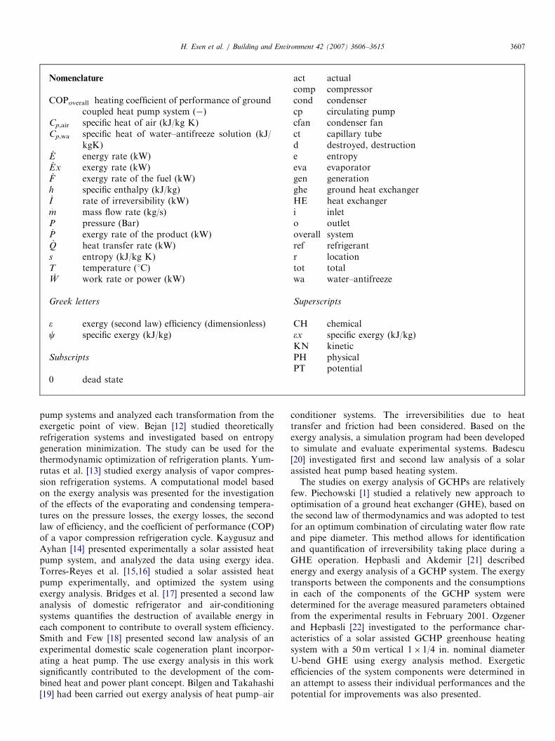
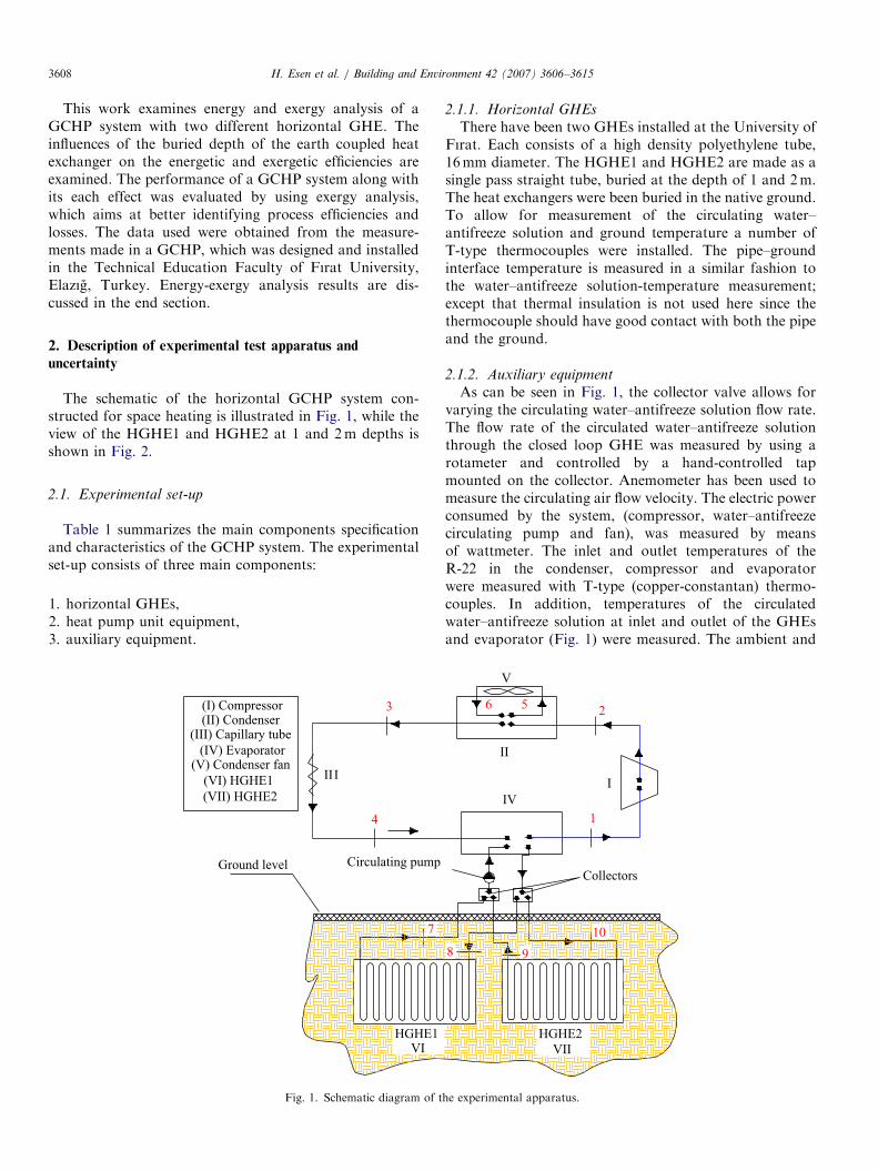
The schematic of the horizontal GCHP system con-structed for space heating is illustrated in Fig. 1, while theview of the HGHE1 and HGHE2 at 1 and 2m depths isshown in Fig. 2.
2.1. Experimental set-up
Table 1 summarizes the main components specificationand characteristics of the GCHP system. The experimentalset-up consists of three main components:
1.
horizontal GHEs, 2. heat pump unit equipment, 3. auxiliary equipment.III
3
4
Ground level
HGHE1VI
7
Circulating pump
(I) Compressor(II) Condenser
(III) Capillary tube
(IV) Evaporator(V) Condenser fan
(VI) HGHE1
(VII) HGHE2
Fig. 1. Schematic diagram of t
2.1.1. Horizontal GHEs
There have been two GHEs installed at the University of
Fırat. Each consists of a high density polyethylene tube,16mm diameter. The HGHE1 and HGHE2 are made as asingle pass straight tube, buried at the depth of 1 and 2m.The heat exchangers were been buried in the native ground.To allow for measurement of the circulating water–antifreeze solution and ground temperature a number ofT-type thermocouples were installed. The pipe–groundinterface temperature is measured in a similar fashion tothe water–antifreeze solution-temperature measurement;except that thermal insulation is not used here since thethermocouple should have good contact with both the pipeand the ground.2.1.2. Auxiliary equipment
As can be seen in Fig. 1, the collector valve allows forvarying the circulating water–antifreeze solution flow rate.The flow rate of the circulated water–antifreeze solutionthrough the closed loop GHE was measured by using arotameter and controlled by a hand-controlled tapmounted on the collector. Anemometer has been used tomeasure the circulating air flow velocity. The electric powerconsumed by the system, (compressor, water–antifreezecirculating pump and fan), was measured by meansof wattmeter. The inlet and outlet temperatures of theR-22 in the condenser, compressor and evaporatorwere measured with T-type (copper-constantan) thermo-couples. In addition, temperatures of the circulatedwater–antifreeze solution at inlet and outlet of the GHEsand evaporator (Fig. 1) were measured. The ambient and
II
I
IV
V
256
1
Collectors
HGHE2
VII
8 9
10
he experimental apparatus.
ARTICLE IN PRESS
Fig. 2. The view of the ground heat exchangers buried at 1 and 2m
depths.
Table 1
Technical features of the experimental set-up
Location: Elazıg, Turkey (lat. 38.411N; long. 39.141E)
Weather information (yearly average values):
Average outdoor temperature 286 (K)
Maximum outdoor temperature 291 (K)
Minimum outdoor temperature 280 (K)
Average relative humidity 56 (%)
Average solar radiation 14.9 (MJ/m2/d)
Average wind velocity 2.5 (ms�1)
Average ground temperature at 1m depth 289 (K)
Room information:
Window area 2.24m2
Wall area 34.63m2
Floor area 16.24m2
Ceiling area 16.24m2
Comfort temperature 293K
Dimensions of the building 55.21m3
Heat pump information:
Capacity 4.279 kW
Compressor type Hermetic
Evaporator type TT3; copper and inner
cooling aluminium
Condenser type HS 10; friterm
Compressor power input 2HP; 1.4 kW
Compressor volumetric flow rate 7.6m3/h
Compressor rotation speed 2900 tr/mn
Condenser fan 2350m3/h, 145W
Evaporating temperature 0 1C
Condensing temperature 54.5 1C
Refrigerant type R-22
Ground heat exchanger information:
Configuration type Horizontal
Pipe material Polyethylene, PX-b
cross link
Length of pipe 50m� 2
Pipe diameter 0.016m
Piping depth 1 and 2m
Pipe distance 0.3m
Circulating pump information:
Type Alarko, NPVO-26-P
Power 40, 62, 83W
H. Esen et al. / Building and Environment 42 (2007) 3606–3615 3609
indoor air temperatures were measured with thermometers.The inlet and outlet pressures of the compressor andevaporator were measured by using Bourdon tube typemanometers.
2.1.3. Heat pump unit equipment
The heat transfer from Earth to the heat pump or fromthe heat pump to Earth is maintained with the fluid orwater–antifreeze solution circulated through the GHEs.The fluid transfers its heat to refrigerant fluid in theevaporator (the water–antifreeze solution to refrigerantheat exchanger). The refrigerant, which flows throughother closed loop in the heat pump, evaporates byabsorbing heat from the water–antifreeze solution circu-lated through the evaporator and then enters the hermeticcompressor. The refrigerant is compressed by the com-pressor and then enters the condenser, where it condenses.After the refrigerant leaves the condenser, the capillarytube provides almost 10 1C superheat that essentially givesa safety margin to reduce the risk of liquid dropletsentering the compressor. A fan blows across the condenserto move the warmed air of the room. A non-toxicpropylene glycol solution, 25% by weight, was circulatedthrough the GHE. In the heating season, the heat exchangefluid (water–antifreeze solution) in the GHE loop collectsheat from the earth and transfers that heat to the room.After the heat exchange fluid absorbs heat from theground, the closed loop GHEs circulates the heat exchangefluid through pipes (see Fig. 1).
The GCHP system connected to a test room with16.24m2 floor area in Fırat University, Elazıg (38.411 N,39.141 E), Turkey, was designed and constructed. Theheating and cooling loads of the test room were 2.5 and3.1 kW at design conditions, respectively. The compressorand other part of the experimental system were selected theaccording to the heating and cooling load of test roomfrom the manufacturer’s catalog data.
2.2. Uncertainty analysis
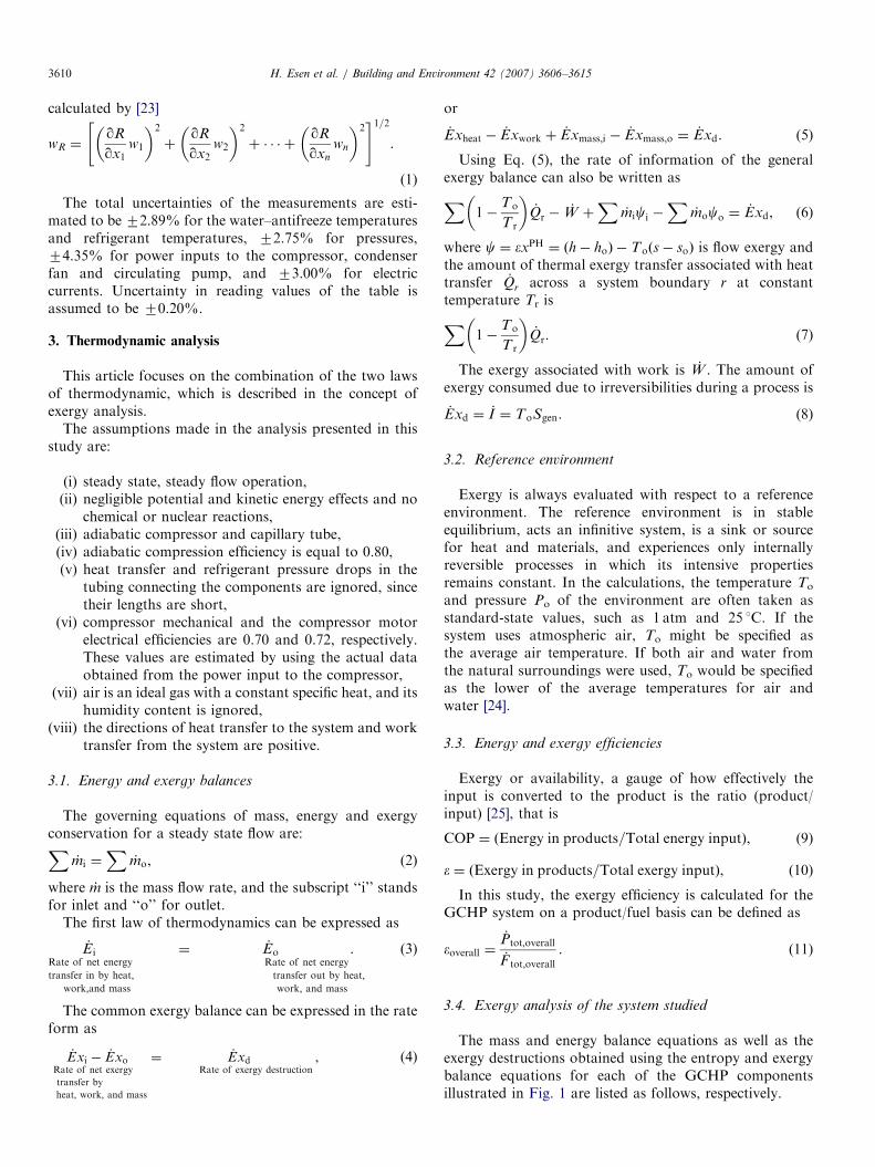
An important issue is the accuracy of the measured dataas well as the results obtained by experimental studies.Uncertainty is a measure of the ‘‘goodness’’ of a result.Without such a measure, it is impossible to judge the fitnessof the value as a basis for making decisions relating tohealth, safety, commerce or scientific excellence.The result R is a given function in terms of the
independent variables. Let wR be the uncertainty inthe result and w1, w2, y, wn be the uncertainties in theindependent variables. The result R is a given function ofthe independent variables x1, x2, x3,y,xn. If the uncertain-ties in the independent variables are all given with sameodds, then uncertainty in the result having these odds is
ARTICLE IN PRESSH. Esen et al. / Building and Environment 42 (2007) 3606–36153610
calculated by [23]
wR ¼qR
qx1w1
� �2
þqR
qx2w2
� �2
þ � � � þqR
qxn
wn
� �2" #1=2
.
(1)
The total uncertainties of the measurements are esti-mated to be 72.89% for the water–antifreeze temperaturesand refrigerant temperatures, 72.75% for pressures,74.35% for power inputs to the compressor, condenserfan and circulating pump, and 73.00% for electriccurrents. Uncertainty in reading values of the table isassumed to be 70.20%.
3. Thermodynamic analysis
This article focuses on the combination of the two lawsof thermodynamic, which is described in the concept ofexergy analysis.
The assumptions made in the analysis presented in thisstudy are:
(i)
steady state, steady flow operation, (ii) negligible potential and kinetic energy effects and nochemical or nuclear reactions,
(iii) adiabatic compressor and capillary tube, (iv) adiabatic compression efficiency is equal to 0.80, (v) heat transfer and refrigerant pressure drops in thetubing connecting the components are ignored, sincetheir lengths are short,
(vi)
compressor mechanical and the compressor motorelectrical efficiencies are 0.70 and 0.72, respectively.These values are estimated by using the actual dataobtained from the power input to the compressor,(vii)
air is an ideal gas with a constant specific heat, and itshumidity content is ignored,(viii)
the directions of heat transfer to the system and worktransfer from the system are positive.3.1. Energy and exergy balances
The governing equations of mass, energy and exergyconservation for a steady state flow are:X
_mi ¼X
_mo, (2)
where _m is the mass flow rate, and the subscript ‘‘i’’ standsfor inlet and ‘‘o’’ for outlet.
The first law of thermodynamics can be expressed as
_E iRate of net energy
transfer in by heat;work;and mass
¼ _EoRate of net energy
transfer out by heat;work; and mass
. (3)
The common exergy balance can be expressed in the rateform as
_Exi � _ExoRate of net exergy
transfer by
heat; work; and mass
¼ _ExdRate of exergy destruction
, (4)
or
_Exheat � _Exwork þ _Exmass;i � _Exmass;o ¼ _Exd. (5)
Using Eq. (5), the rate of information of the generalexergy balance can also be written asX
1�To
T r
� �_Qr �
_W þX
_mici �X
_moco ¼_Exd, (6)
where c ¼ �xPH ¼ ðh� hoÞ � Toðs� soÞ is flow exergy andthe amount of thermal exergy transfer associated with heattransfer _Qr across a system boundary r at constanttemperature Tr isX
1�To
T r
� �_Qr: (7)
The exergy associated with work is _W . The amount ofexergy consumed due to irreversibilities during a process is
_Exd ¼ _I ¼ ToSgen. (8)
3.2. Reference environment
Exergy is always evaluated with respect to a referenceenvironment. The reference environment is in stableequilibrium, acts an infinitive system, is a sink or sourcefor heat and materials, and experiences only internallyreversible processes in which its intensive propertiesremains constant. In the calculations, the temperature To
and pressure Po of the environment are often taken asstandard-state values, such as 1 atm and 25 1C. If thesystem uses atmospheric air, To might be specified asthe average air temperature. If both air and water fromthe natural surroundings were used, To would be specifiedas the lower of the average temperatures for air andwater [24].
3.3. Energy and exergy efficiencies
Exergy or availability, a gauge of how effectively theinput is converted to the product is the ratio (product/input) [25], that is
COP ¼ ðEnergy in products=Total energy inputÞ, (9)
� ¼ ðExergy in products=Total exergy inputÞ, (10)
In this study, the exergy efficiency is calculated for theGCHP system on a product/fuel basis can be defined as
�overall ¼_Ptot;overall
_F tot;overall
. (11)
3.4. Exergy analysis of the system studied
The mass and energy balance equations as well as theexergy destructions obtained using the entropy and exergybalance equations for each of the GCHP componentsillustrated in Fig. 1 are listed as follows, respectively.
ARTICLE IN PRESS
-5
0
5
10
15
20
25
30
Janu
ary
Febru
ary
Mar
ch
Apr
ilM
ayJu
neJu
ly
Aug
ust
Septe
mbe
r
Oct
ober
Nov
embe
r
Dec
embe
r
Months
Tem
per
atu
re (
° C)
0
10
20
30
40
50
60
70
80R
elat
ive
hu
mid
ity
(%
)
Air Ground 1.0m Ground 2.0m Relative humidity
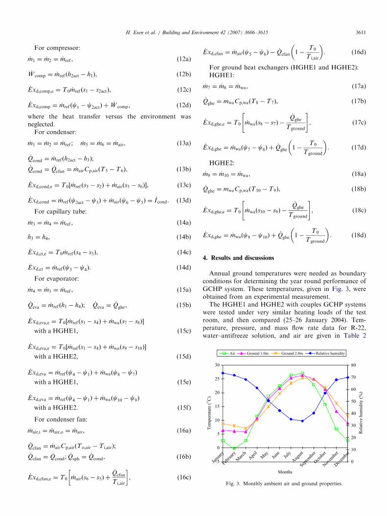
Fig. 3. Monthly ambient air and ground properties.
H. Esen et al. / Building and Environment 42 (2007) 3606–3615 3611
For compressor:
_m1 ¼ _m2 ¼ _mref , (12a)
_W comp ¼ _mref ðh2act � h1Þ, (12b)
_Exd;comp;e ¼ T0 _mref ðs1 � s2actÞ, (12c)
_Exd;comp ¼ _mref ðc1 � c2actÞ þ_W comp, (12d)
where the heat transfer versus the environment wasneglected.
For condenser:
_m1 ¼ _m2 ¼ _mref ; _m5 ¼ _m6 ¼ _mair, (13a)
_Qcond ¼ _mref ðh2act � h3Þ;
_Qcond ¼_Qcfan ¼ _mairCp;airðT5 � T6Þ, ð13bÞ
_Exd;cond;e ¼ T0½ _mref ðs3 � s2Þ þ _mairðs5 � s6Þ�, (13c)
_Exd;cond ¼ _mref ðc2act � c3Þ þ _mairðc6 � c5Þ ¼_I cond. (13d)
For capillary tube:
_m3 ¼ _m4 ¼ _mref , (14a)
h3 ¼ h4, (14b)
_Exd;ct;e ¼ T0 _mref ðs4 � s3Þ, (14c)
_Exd;ct ¼ _mref ðc3 � c4Þ. (14d)
For evaporator:
_m4 ¼ _m1 ¼ _mref , (15a)
_Qeva ¼ _mref ðh1 � h4Þ; _Qeva ¼_Qghe, (15b)
_Exd;eva;e ¼ T0½ _mref ðs1 � s4Þ þ _mwaðs7 � s8Þ�
with a HGHE1, ð15cÞ
_Exd;eva;e ¼ T0½ _mref ðs1 � s4Þ þ _mwaðs9 � s10Þ�
with a HGHE2, ð15dÞ
_Exd;eva ¼ _mref ðc4 � c1Þ þ _mwaðc8 � c7Þ
with a HGHE1, ð15eÞ
_Exd;eva ¼ _mref ðc4 � c1Þ þ _mwaðc10 � c9Þ
with a HGHE2. ð15fÞ
For condenser fan:
_mair;i ¼ _mair;o ¼ _mair, (16a)
_Qcfan ¼ _mairCp;airðTo;air � T i;airÞ;
_Qcfan ¼_Qcond; _Qsph ¼
_Qcond, ð16bÞ
_Exd;cfan;e ¼ T0 _mairðs6 � s5Þ þ_Qcfan
T i;air
� �, (16c)
_Exd;cfan ¼ _mairðc5 � c6Þ �_Qcfan 1�
T0
T i;air
� �. (16d)
For ground heat exchangers (HGHE1 and HGHE2):HGHE1:
_m7 ¼ _m8 ¼ _mwa, (17a)
_Qghe ¼ mwaCp;waðT8 � T7Þ, (17b)
_Exd;ghe;e ¼ T0 _mwaðs8 � s7Þ �_Qghe
Tground
" #, (17c)
_Exd;ghe ¼ _mwaðc7 � c8Þ þ_Qghe 1�
T0
Tground
� �. (17d)
HGHE2:
_m9 ¼ _m10 ¼ _mwa, (18a)
_Qghe ¼ mwaCp;waðT10 � T9Þ, (18b)
_Exd;ghe;e ¼ T0 _mwaðs10 � s9Þ �_Qghe
Tground
" #, (18c)
_Exd;ghe ¼ _mwaðc9 � c10Þ þ_Qghe 1�
T0
Tground
� �. (18d)
4. Results and discussions
Annual ground temperatures were needed as boundaryconditions for determining the year round performance ofGCHP system. These temperatures, given in Fig. 3, wereobtained from an experimental measurement.The HGHE1 and HGHE2 with couples GCHP systems
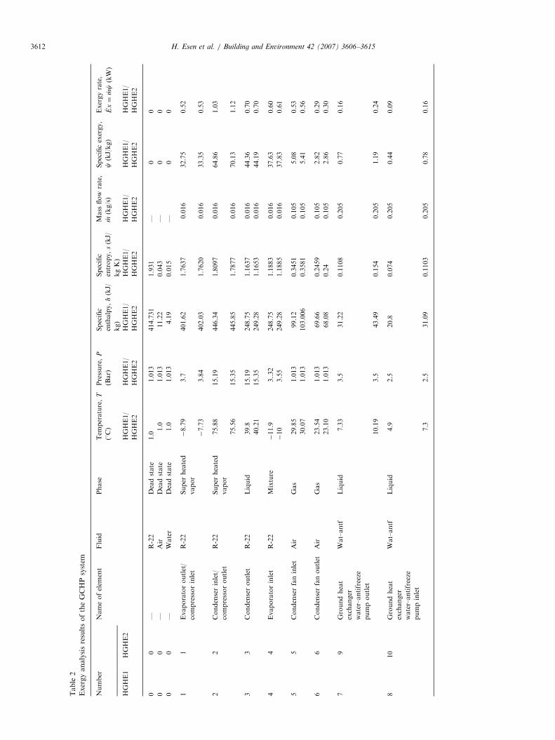
were tested under very similar heating loads of the testroom, and then compared (25–26 January 2004). Tem-perature, pressure, and mass flow rate data for R-22,water–antifreeze solution, and air are given in Table 2
ARTICLE IN PRESS
Table
2
ExergyanalysisresultsoftheGCHPsystem
Number
Nameofelem
ent
Fluid
Phase
Tem
perature,
T
(1C)
Pressure,
P
(Bar)
Specific
enthalpy,
h(kJ/
kg)
Specific
entropy,
s(kJ/
kgK)
Mass
flow
rate,
_ m(kg/s)
Specificexergy,
c(kJ/kg)
Exergyrate,
_ Ex¼_ mc
(kW)
HGHE1
HGHE2
HGHE1/
HGHE2
HGHE1/
HGHE2
HGHE1/
HGHE2
HGHE1/
HGHE2
HGHE1/
HGHE2
HGHE1/
HGHE2
HGHE1/
HGHE2
00
—R-22
Deadstate
1.0
1.013
414.731
1.931
—0
0
00
—Air
Deadstate
1.0
1.013
11.22
0.043
—0
0
00
—Water
Deadstate
1.0
1.013
4.19
0.015
—0
0
11
Evaporatoroutlet/
compressorinlet
R-22
Super
heated
vapor
�8.79
3.7
401.62
1.7637
0.016
32.75
0.52
�7.73
3.84
402.03
1.7620
0.016
33.35
0.53
22
Condenserinlet/
compressoroutlet
R-22
Super
heated
vapor
75.88
15.19
446.34
1.8097
0.016
64.86
1.03
75.56
15.35
445.85
1.7877
0.016
70.13
1.12
33
Condenseroutlet
R-22
Liquid
39.8
15.19
248.75
1.1637
0.016
44.36
0.70
40.21
15.35
249.28
1.1653
0.016
44.19
0.70
44
Evaporatorinlet
R-22
Mixture
�11.9
3..32
248.75
1.1883
0.016
37.63
0.60
�10
3.55
249.28
1.1885
0.016
37.83
0.61
55
Condenserfaninlet
Air
Gas
29.85
1.013
99.12
0.3451
0.105
5.08
0.53
30.07
1.013
103.006
0.3581
0.105
5.41
0.56
66
Condenserfanoutlet
Air
Gas
23.54
1.013
69.66
0.2459
0.105
2.82
0.29
23.10
1.013
68.08
0.24
0.105
2.86
0.30
79
Groundheat
exchanger
water–antifreeze
pumpoutlet
Wat–antf
Liquid
7.33
3.5
31.22
0.1108
0.205
0.77
0.16
10.19
3.5
43.49
0.154
0.205
1.19
0.24
810
Groundheat
exchanger
water–antifreeze
pumpinlet
Wat–antf
Liquid
4.9
2.5
20.8
0.074
0.205
0.44
0.09
7.3
2.5
31.09
0.1103
0.205
0.78
0.16
H. Esen et al. / Building and Environment 42 (2007) 3606–36153612
ARTICLE IN PRESSH. Esen et al. / Building and Environment 42 (2007) 3606–3615 3613
according to their state numbers specified in Fig. 1. In thisstudy, To and Po were taken as 1 1C and 101.325 kPa,respectively, which were the values measured at the timewhen the GCHP system data were obtained. The thermo-dynamic properties of air, water and R-22 are obtainedfrom Refs. [26,27].
4.1. Energetic evaluation
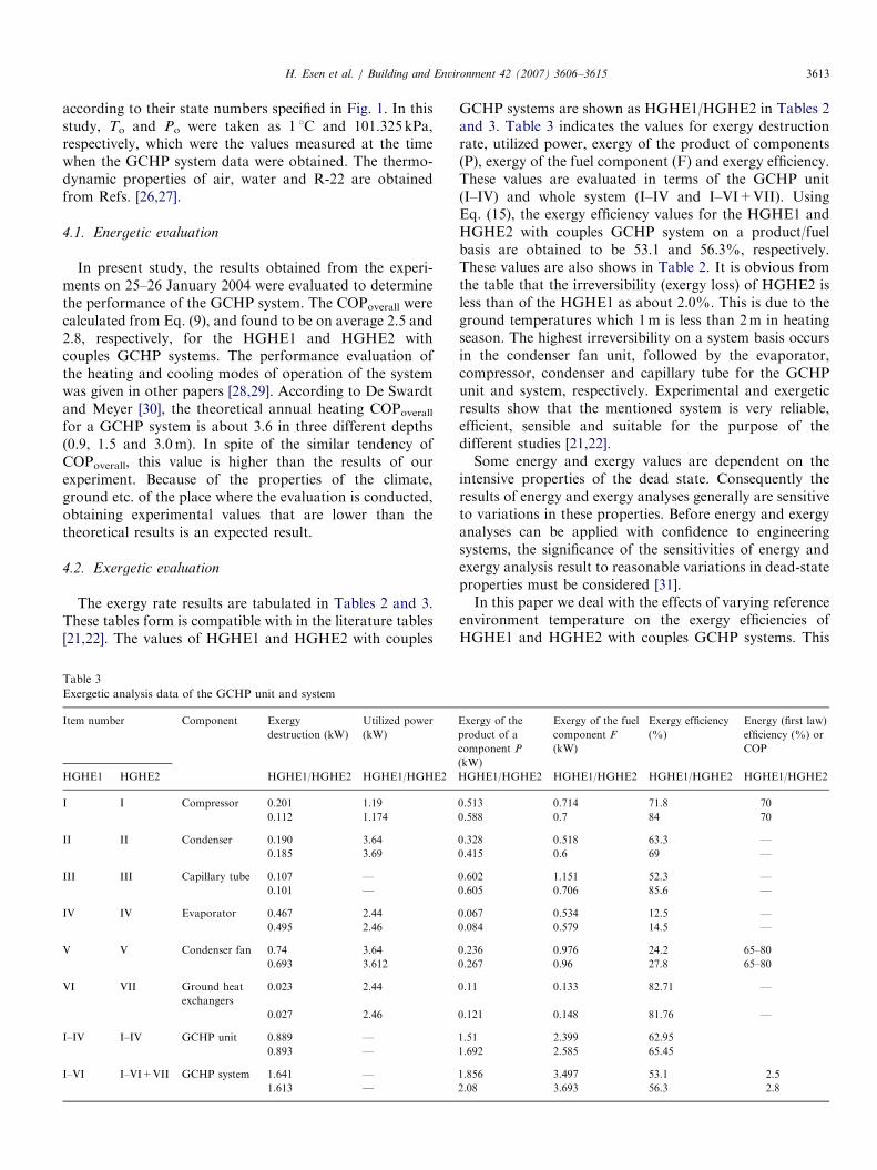
In present study, the results obtained from the experi-ments on 25–26 January 2004 were evaluated to determinethe performance of the GCHP system. The COPoverall werecalculated from Eq. (9), and found to be on average 2.5 and2.8, respectively, for the HGHE1 and HGHE2 withcouples GCHP systems. The performance evaluation ofthe heating and cooling modes of operation of the systemwas given in other papers [28,29]. According to De Swardtand Meyer [30], the theoretical annual heating COPoverall
for a GCHP system is about 3.6 in three different depths(0.9, 1.5 and 3.0m). In spite of the similar tendency ofCOPoverall, this value is higher than the results of ourexperiment. Because of the properties of the climate,ground etc. of the place where the evaluation is conducted,obtaining experimental values that are lower than thetheoretical results is an expected result.
4.2. Exergetic evaluation
The exergy rate results are tabulated in Tables 2 and 3.These tables form is compatible with in the literature tables[21,22]. The values of HGHE1 and HGHE2 with couples
Table 3
Exergetic analysis data of the GCHP unit and system
Item number Component Exergy
destruction (kW)
Utilized power
(kW)
HGHE1 HGHE2 HGHE1/HGHE2 HGHE1/HGHE2
I I Compressor 0.201 1.19
0.112 1.174
II II Condenser 0.190 3.64
0.185 3.69
III III Capillary tube 0.107 —
0.101 —
IV IV Evaporator 0.467 2.44
0.495 2.46
V V Condenser fan 0.74 3.64
0.693 3.612
VI VII Ground heat
exchangers
0.023 2.44
0.027 2.46
I–IV I–IV GCHP unit 0.889 —
0.893 —
I–VI I–VI+VII GCHP system 1.641 —
1.613 —
GCHP systems are shown as HGHE1/HGHE2 in Tables 2and 3. Table 3 indicates the values for exergy destructionrate, utilized power, exergy of the product of components(P), exergy of the fuel component (F) and exergy efficiency.These values are evaluated in terms of the GCHP unit(I–IV) and whole system (I–IV and I–VI+VII). UsingEq. (15), the exergy efficiency values for the HGHE1 andHGHE2 with couples GCHP system on a product/fuelbasis are obtained to be 53.1 and 56.3%, respectively.These values are also shows in Table 2. It is obvious fromthe table that the irreversibility (exergy loss) of HGHE2 isless than of the HGHE1 as about 2.0%. This is due to theground temperatures which 1m is less than 2m in heatingseason. The highest irreversibility on a system basis occursin the condenser fan unit, followed by the evaporator,compressor, condenser and capillary tube for the GCHPunit and system, respectively. Experimental and exergeticresults show that the mentioned system is very reliable,efficient, sensible and suitable for the purpose of thedifferent studies [21,22].Some energy and exergy values are dependent on the
intensive properties of the dead state. Consequently theresults of energy and exergy analyses generally are sensitiveto variations in these properties. Before energy and exergyanalyses can be applied with confidence to engineeringsystems, the significance of the sensitivities of energy andexergy analysis result to reasonable variations in dead-stateproperties must be considered [31].In this paper we deal with the effects of varying reference
environment temperature on the exergy efficiencies ofHGHE1 and HGHE2 with couples GCHP systems. This
Exergy of the
product of a
component P
(kW)
Exergy of the fuel
component F
(kW)
Exergy efficiency
(%)
Energy (first law)
efficiency (%) or
COP
HGHE1/HGHE2 HGHE1/HGHE2 HGHE1/HGHE2 HGHE1/HGHE2
0.513 0.714 71.8 70
0.588 0.7 84 70
0.328 0.518 63.3 —
0.415 0.6 69 —
0.602 1.151 52.3 —
0.605 0.706 85.6 —
0.067 0.534 12.5 —
0.084 0.579 14.5 —
0.236 0.976 24.2 65–80
0.267 0.96 27.8 65–80
0.11 0.133 82.71 —
0.121 0.148 81.76 —
1.51 2.399 62.95
1.692 2.585 65.45
1.856 3.497 53.1 2.5
2.08 3.693 56.3 2.8
ARTICLE IN PRESS
0.3
0.35
0.4
0.45
0.5
0.55
0.6
-5 1 5 10 15 20 25 30
Temperature (°C)
Exer
gy e
ffic
iency
HGHE1
HGHE2
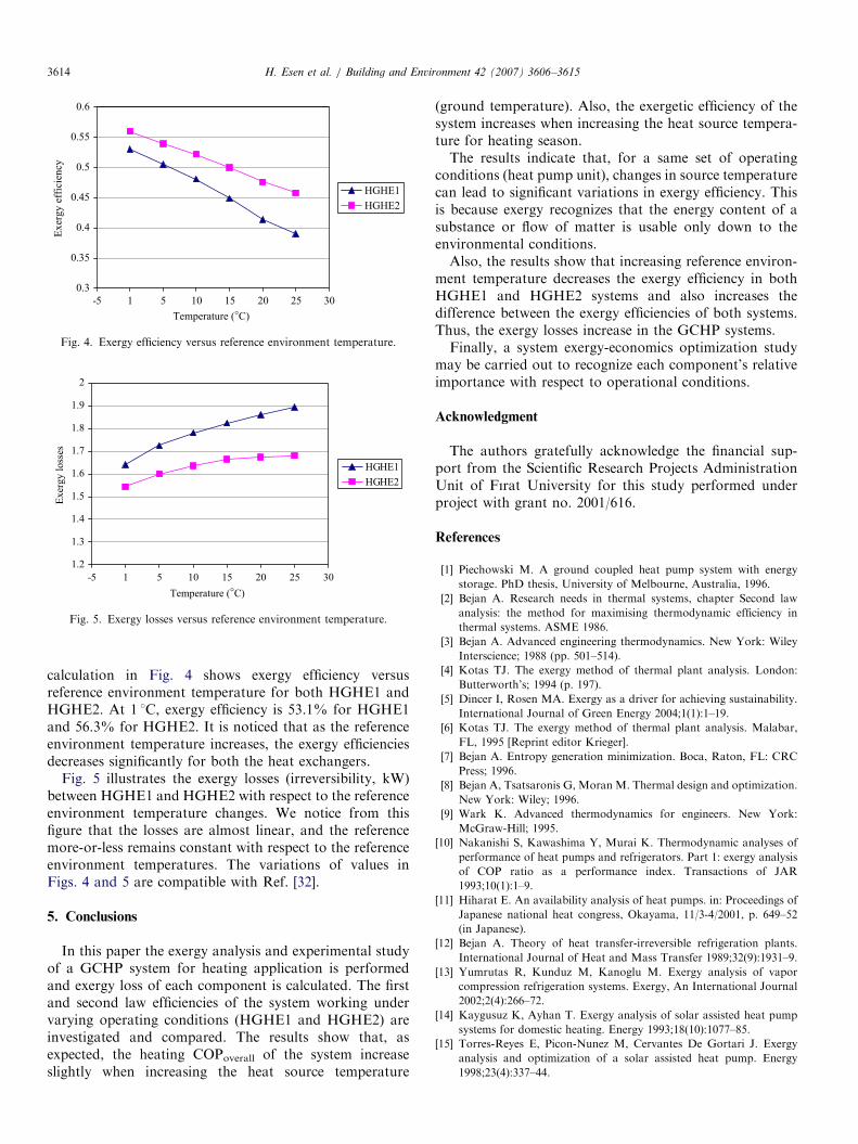
Fig. 4. Exergy efficiency versus reference environment temperature.
1.2
1.3
1.4
1.5
1.6
1.7
1.8
1.9
2
-5 1 5 10 15 20 25 30
Temperature (°C)
Exer
gy l
oss
es
HGHE1
HGHE2
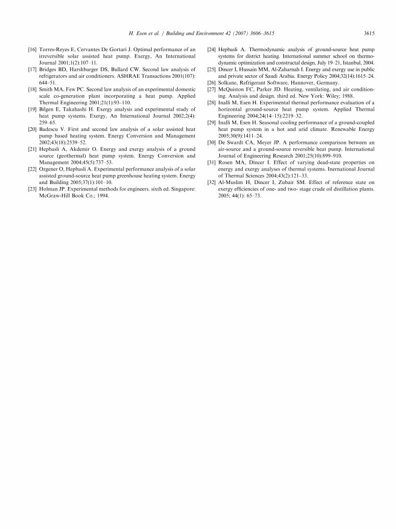
Fig. 5. Exergy losses versus reference environment temperature.
H. Esen et al. / Building and Environment 42 (2007) 3606–36153614
calculation in Fig. 4 shows exergy efficiency versusreference environment temperature for both HGHE1 andHGHE2. At 1 1C, exergy efficiency is 53.1% for HGHE1and 56.3% for HGHE2. It is noticed that as the referenceenvironment temperature increases, the exergy efficienciesdecreases significantly for both the heat exchangers.
Fig. 5 illustrates the exergy losses (irreversibility, kW)between HGHE1 and HGHE2 with respect to the referenceenvironment temperature changes. We notice from thisfigure that the losses are almost linear, and the referencemore-or-less remains constant with respect to the referenceenvironment temperatures. The variations of values inFigs. 4 and 5 are compatible with Ref. [32].
5. Conclusions
In this paper the exergy analysis and experimental studyof a GCHP system for heating application is performedand exergy loss of each component is calculated. The firstand second law efficiencies of the system working undervarying operating conditions (HGHE1 and HGHE2) areinvestigated and compared. The results show that, asexpected, the heating COPoverall of the system increaseslightly when increasing the heat source temperature
(ground temperature). Also, the exergetic efficiency of thesystem increases when increasing the heat source tempera-ture for heating season.The results indicate that, for a same set of operating
conditions (heat pump unit), changes in source temperaturecan lead to significant variations in exergy efficiency. Thisis because exergy recognizes that the energy content of asubstance or flow of matter is usable only down to theenvironmental conditions.Also, the results show that increasing reference environ-
ment temperature decreases the exergy efficiency in bothHGHE1 and HGHE2 systems and also increases thedifference between the exergy efficiencies of both systems.Thus, the exergy losses increase in the GCHP systems.Finally, a system exergy-economics optimization study
may be carried out to recognize each component’s relativeimportance with respect to operational conditions.
Acknowledgment
The authors gratefully acknowledge the financial sup-port from the Scientific Research Projects AdministrationUnit of Fırat University for this study performed underproject with grant no. 2001/616.
References
[1] Piechowski M. A ground coupled heat pump system with energy
storage. PhD thesis, University of Melbourne, Australia, 1996.
[2] Bejan A. Research needs in thermal systems, chapter Second law
analysis: the method for maximising thermodynamic efficiency in
thermal systems. ASME 1986.
[3] Bejan A. Advanced engineering thermodynamics. New York: Wiley
Interscience; 1988 (pp. 501–514).
[4] Kotas TJ. The exergy method of thermal plant analysis. London:
Butterworth’s; 1994 (p. 197).
[5] Dincer I, Rosen MA. Exergy as a driver for achieving sustainability.
International Journal of Green Energy 2004;1(1):1–19.
[6] Kotas TJ. The exergy method of thermal plant analysis. Malabar,
FL, 1995 [Reprint editor Krieger].
[7] Bejan A. Entropy generation minimization. Boca, Raton, FL: CRC
Press; 1996.
[8] Bejan A, Tsatsaronis G, Moran M. Thermal design and optimization.
New York: Wiley; 1996.
[9] Wark K. Advanced thermodynamics for engineers. New York:
McGraw-Hill; 1995.
[10] Nakanishi S, Kawashima Y, Murai K. Thermodynamic analyses of
performance of heat pumps and refrigerators. Part 1: exergy analysis
of COP ratio as a performance index. Transactions of JAR
1993;10(1):1–9.
[11] Hiharat E. An availability analysis of heat pumps. in: Proceedings of
Japanese national heat congress, Okayama, 11/3-4/2001, p. 649–52
(in Japanese).
[12] Bejan A. Theory of heat transfer-irreversible refrigeration plants.
International Journal of Heat and Mass Transfer 1989;32(9):1931–9.
[13] Yumrutas R, Kunduz M, Kanoglu M. Exergy analysis of vapor
compression refrigeration systems. Exergy, An International Journal
2002;2(4):266–72.
[14] Kaygusuz K, Ayhan T. Exergy analysis of solar assisted heat pump
systems for domestic heating. Energy 1993;18(10):1077–85.
[15] Torres-Reyes E, Picon-Nunez M, Cervantes De Gortari J. Exergy
analysis and optimization of a solar assisted heat pump. Energy
1998;23(4):337–44.
ARTICLE IN PRESSH. Esen et al. / Building and Environment 42 (2007) 3606–3615 3615
[16] Torres-Reyes E, Cervantes De Gortari J. Optimal performance of an
irreversible solar assisted heat pump. Exergy, An International
Journal 2001;1(2):107–11.
[17] Bridges BD, Harshbarger DS, Bullard CW. Second law analysis of
refrigerators and air conditioners. ASHRAE Transactions 2001(107):
644–51.
[18] Smith MA, Few PC. Second law analysis of an experimental domestic
scale co-generation plant incorporating a heat pump. Applied
Thermal Engineering 2001;21(1):93–110.
[19] Bilgen E, Takahashi H. Exergy analysis and experimental study of
heat pump systems. Exergy, An International Journal 2002;2(4):
259–65.
[20] Badescu V. First and second law analysis of a solar assisted heat
pump based heating system. Energy Conversion and Management
2002;43(18):2539–52.
[21] Hepbasli A, Akdemir O. Energy and exergy analysis of a ground
source (geothermal) heat pump system. Energy Conversion and
Management 2004;45(5):737–53.
[22] Ozgener O, Hepbasli A. Experimental performance analysis of a solar
assisted ground-source heat pump greenhouse heating system. Energy
and Building 2005;37(1):101–10.
[23] Holman JP. Experimental methods for engineers. sixth ed. Singapore:
McGraw-Hill Book Co.; 1994.
[24] Hepbasli A. Thermodynamic analysis of ground-source heat pump
systems for district heating. International summer school on thermo-
dynamic optimization and constructal design, July 19–21, Istanbul, 2004.
[25] Dincer I, Hussain MM, Al-Zaharnah I. Energy and exergy use in public
and private sector of Saudi Arabia. Energy Policy 2004;32(14):1615–24.
[26] Solkane, Refrigerant Software, Hannover, Germany.
[27] McQuiston FC, Parker JD. Heating, ventilating, and air condition-
ing. Analysis and design. third ed. New York: Wiley; 1988.
[28] Inalli M, Esen H. Experimental thermal performance evaluation of a
horizontal ground-source heat pump system. Applied Thermal
Engineering 2004;24(14–15):2219–32.
[29] Inalli M, Esen H. Seasonal cooling performance of a ground-coupled
heat pump system in a hot and arid climate. Renewable Energy
2005;30(9):1411–24.
[30] De Swardt CA, Meyer JP. A performance comparison between an
air-source and a ground-source reversible heat pump. International
Journal of Engineering Research 2001;25(10):899–910.
[31] Rosen MA, Dincer I. Effect of varying dead-state properties on
energy and exergy analyses of thermal systems. Inernational Journal
of Thermal Sciences 2004;43(2):121–33.
[32] Al-Muslim H, Dincer I, Zubair SM. Effect of reference state on
exergy efficiencies of one- and two- stage crude oil distillation plants.
2005; 44(1): 65–73.
Related Documents