ENERGIZING YOUR WORLD IEC Contactors & Overloads 3 & 4 Pole IEC Contactors • Overloads • Accessories

Welcome message from author
This document is posted to help you gain knowledge. Please leave a comment to let me know what you think about it! Share it to your friends and learn new things together.
Transcript
E N E R G I Z I N G Y O U R W O R L DE N E R G I Z I N G Y O U R W O R L D
I E C C o n t a c t o r s & O v e r l o a d s
3 & 4 P o l e I E C C o n t a c t o r s • O v e r l o a d s • A c c e s s o r i e s
TC Electric Controls Catalog Cover Contact and Overloads v1 no spreads.indd 1 1/12/2017 1:02:55 PM
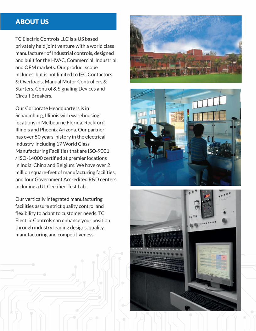
ABOUT US
TC Electric Controls LLC is a US based
privately held joint venture with a world class
manufacturer of Industrial controls, designed
and built for the HVAC, Commercial, Industrial
and OEM markets. Our product scope
includes, but is not limited to IEC Contactors
& Overloads, Manual Motor Controllers &
Starters, Control & Signaling Devices and
Circuit Breakers.
Our Corporate Headquarters is in
Schaumburg, Illinois with warehousing
locations in Melbourne Florida, Rockford
Illinois and Phoenix Arizona. Our partner
has over 50 years’ history in the electrical
industry, including 17 World Class
Manufacturing Facilities that are ISO-9001
/ ISO-14000 certified at premier locations
in India, China and Belgium. We have over 2
million square-feet of manufacturing facilities,
and four Government Accredited R&D centers
including a UL Certified Test Lab.
Our vertically integrated manufacturing
facilities assure strict quality control and
flexibility to adapt to customer needs. TC
Electric Controls can enhance your position
through industry leading designs, quality,
manufacturing and competitiveness.
TC Electric Controls Catalog Cover Contact and Overloads v1 no spreads.indd 2 1/12/2017 1:02:56 PM
θθθθθ
φ
φ
φ
φ
Sealed
Inrush
Sealed
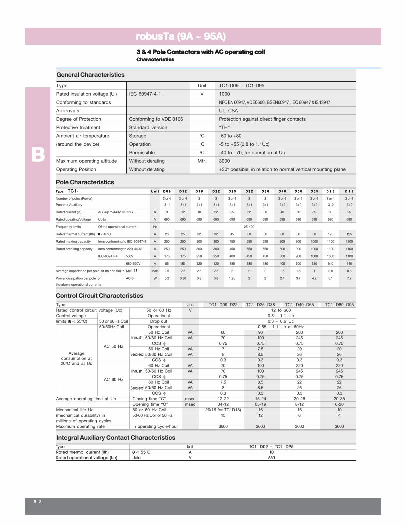
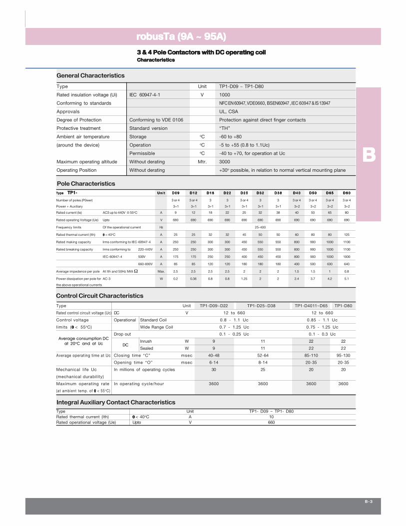
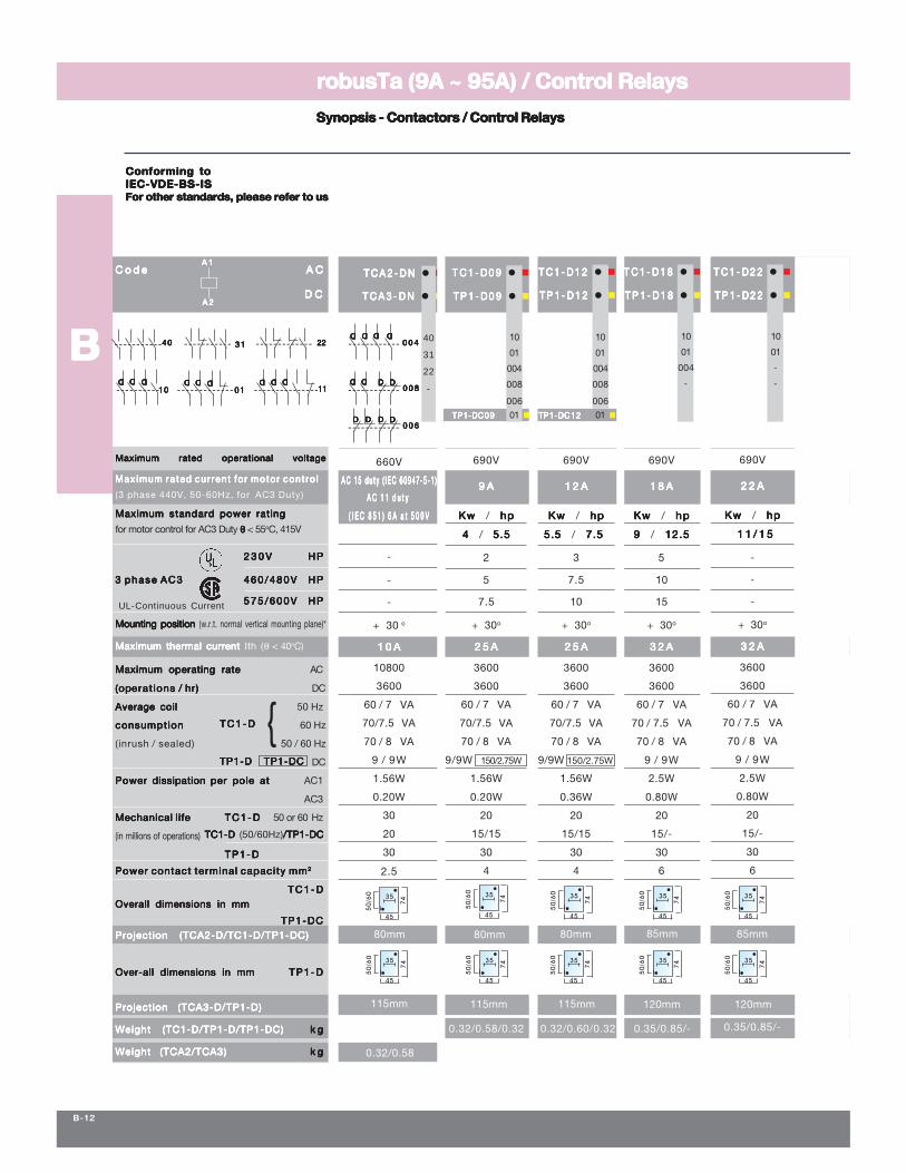
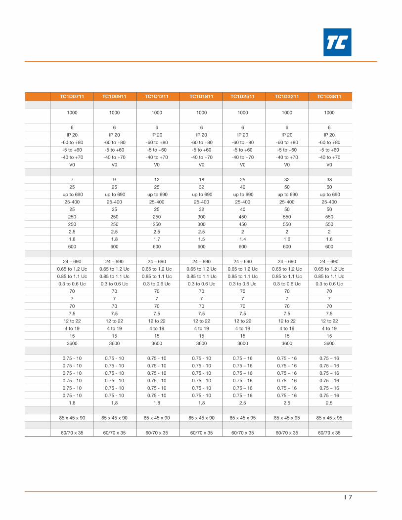
Type Unit TC1- D09 ~ TC1- D95Rated thermal current (Ith) θθθθθ < 55oC A 10Rated operational voltage (Ue) Upto V 660
Inrush
θθθθθ
Ω
θθθθθ
Ω
~
θθθθθ
θθθθθ
Average consumption DCat 20oC and at Uc DC
~θθθθθ
φ
Mil
lio
ns
of
op
era
tin
gc
yc
les
725430 368765
0.01
0.02
0.06
0.03
0.04
0.05
0.10
0.08
0.20
15080 240 390 570109 20 40 108 192 300 480
0.40
0.801.00
0.60
50
TC
1D
09
/T
P1
D0
9
132
TC
1D
12
/T
P1
D1
2
TC
1D
18
/T
P1
D1
8
TC
1D
25
/T
P1
D2
5T
C1
D2
2/
TP
1D
22
TC
1D
40
/T
P1
D4
0
TC
1D
32
/T
P1
D3
2
TC
1D
50
/T
P1
D5
0
TC
1D
65
/T
P1
D6
5T
C1
D8
0/
TP
1D
80
TC
1D
95
/T
P1
D9
5
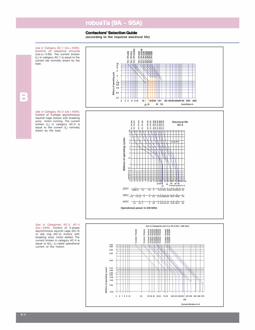
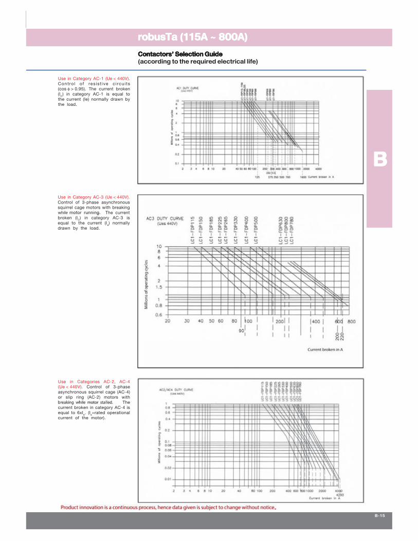
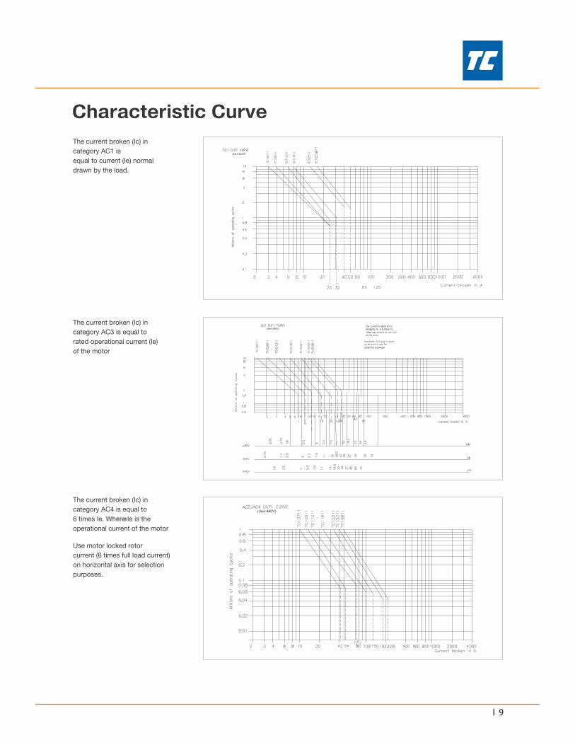
Use in Categories AC-2 or AC-4 (Ve < 440 Vac)
228
TC
1D
38
/T
P1
D3
8
Current Broken in A
7
Operational power in kW-50Hz
2
Mil
lio
ns
of
op
era
tin
gc
yc
les
32.21.50.75
440V1.5 2.2 3
0.55
380V
220V0.75 1.5
0.8
0.2
20 43 65
0.60.50.4
0.7
0.9
1
1.5
7
3
4
6
5T
C1
-D2
2
TC
1-D
18
TC
1-D
12
TC
1-D
09
9
8
10
18.5
30
37
2218.515117.55.54
94 5.5 221115 25
42.2 3 117.55.5 15
75555237
45 55 57 80
302522 4537
50
45
Current broken in A12
108 109
25
18
322015 40 140
9580
7565 120100
Long life
TC
1-D
32
TC
1-D
38
TC
1-D
95
TC
1-D
80
TC
1-D
50
TC
1-D
40
TC
1-D
25
TC
1-D
65
Electrical life
22 38
AC-3
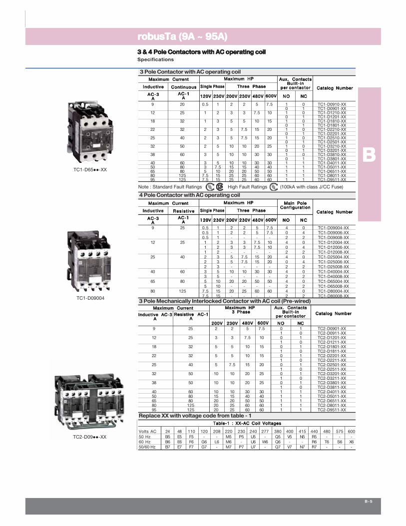
AC-1AC-1AC-1AC-1AC-1AAAAA 230V230V230V230V230V 480V480V480V480V480V200V200V200V200V200V230V230V230V230V230V120V120V120V120V120V N ON ON ON ON O N CN CN CN CN C600V600V600V600V600V
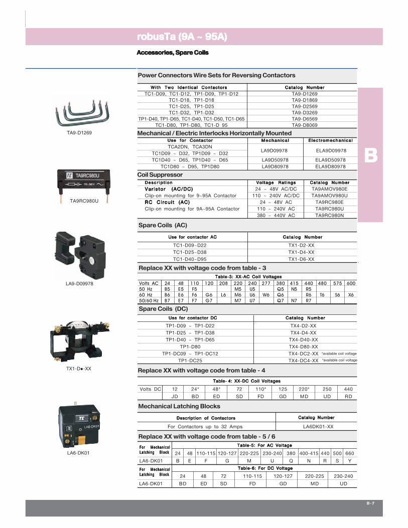
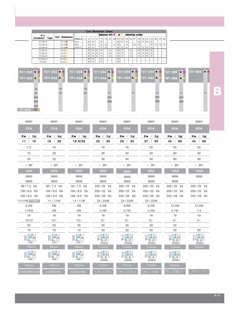
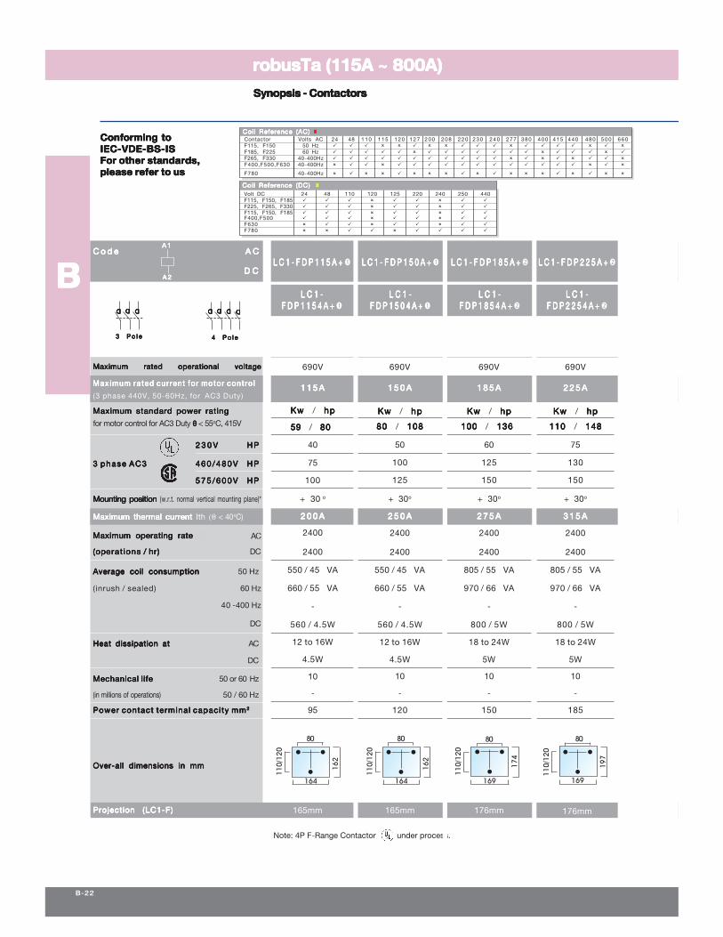
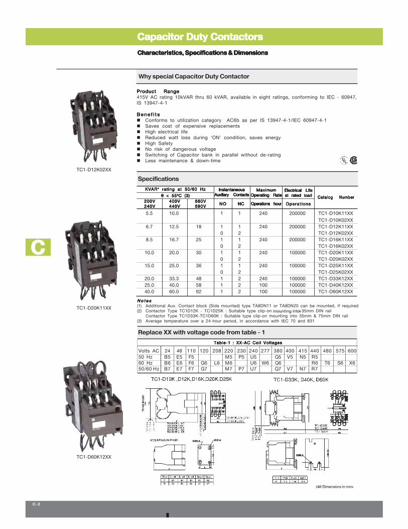
Volts AC 24 48 110 120 208 220 240 277 380 415 440 480 575 60050 Hz B5 E5 F5 M5 U5 Q5 N5 R560 Hz B6 E6 F6 G6 L6 M6 U6 W6 Q6 R6 T6 S6 X650/60 Hz B7 E7 F7 G7 M7 U7 Q7 N7 R7
W *
D *
W *D *
φφ
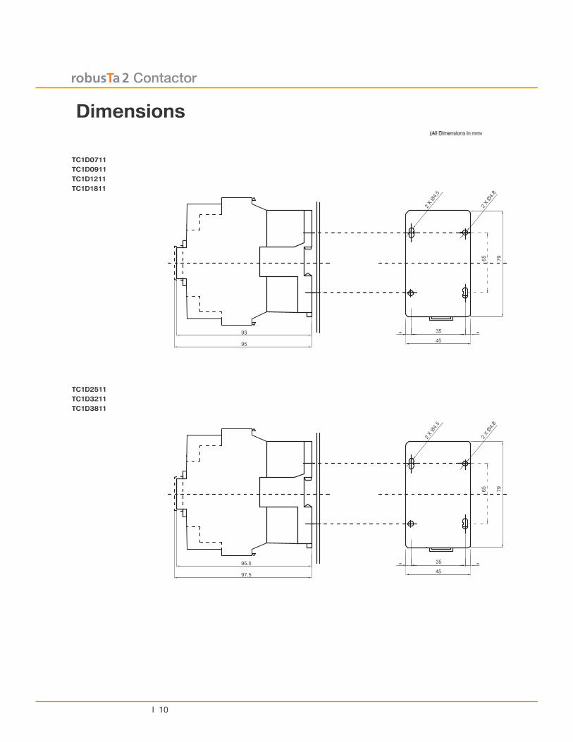
φ
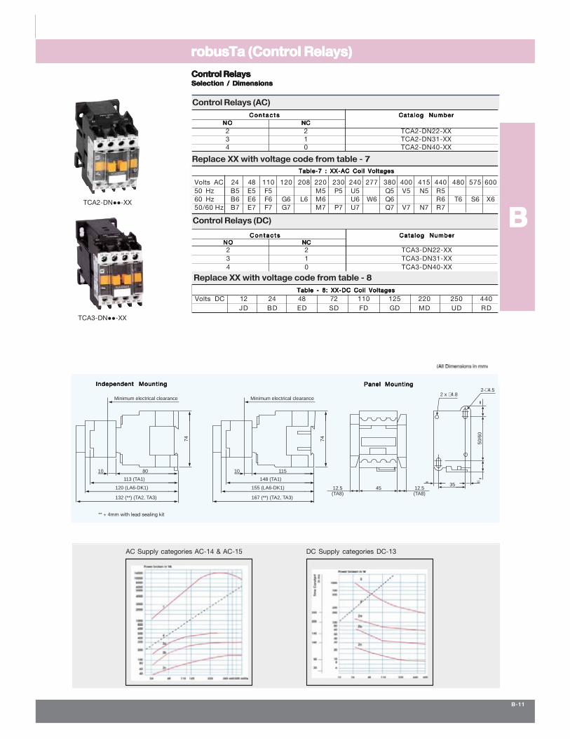
74
Minimum electrical clearance
80
113 (TA1)
12.5(TA8)
4535
12.5(TA8)
120 (LA6-DK1)
132 (**) (TA2, TA3)
10
50
/60
2- 4.52 x 4.8
74
Minimum electrical clearance
115
148 (TA1)
155 (LA6-DK1)
167 (**) (TA2, TA3)
10
40
31
22
-
50
/60
45
7435
50
/60
45
7435
50
/60
45
7435
50
/60
45
7435
50
/60
45
7435
------------
DDDDD DDDDD
DDDDD DDDDD-----------
-------------
DDDDD DDDDD DDDDD
-----------
DDDDD DDDDD DDDDD
---------------
-------------
----------
DDDDD DDDDD DDDDD
------------
DDDDD DDDDD
DDDDD DDDDD
------------DDDDDDDDDDDDDDD
UL-Continuous Current
50
/60
45
7435
50
/60
45
7435
50
/60
45
7435
50
/60
45
7435
50
/60
45
7435
θθθθθ
θ
[
DDDDD
50
/60
56
8440
50
/60
56
8440
50
/60
56
8440
75(3P)/85(4P)
100/
110
12
740
75(3P)/85(4P)
100/
110
12
740
75(3P)/85(4P)
100/
110
12
740
75(3P)/85(4P)
100/
110
12
740
50
/60
56
8440
50
/60
56
8440
50
/60
56
8440
75(3P)/85(4P)
100/
110
12
740
75(3P)/85(4P)
100/
110
12
740
75(3P)/85(4P)
100/
110
12
740
75(3P)/85(4P)
100/
110
12
740
75(3P)/85(4P)
100/
110
12
740
Replace with Replace with Replace with Replace with Replace with ororororor following codesfollowing codesfollowing codesfollowing codesfollowing codes
θθθθθ
θθθθθ
Ω
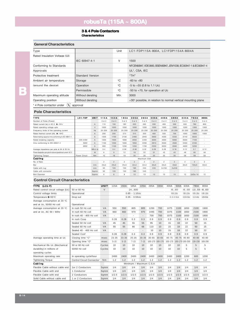
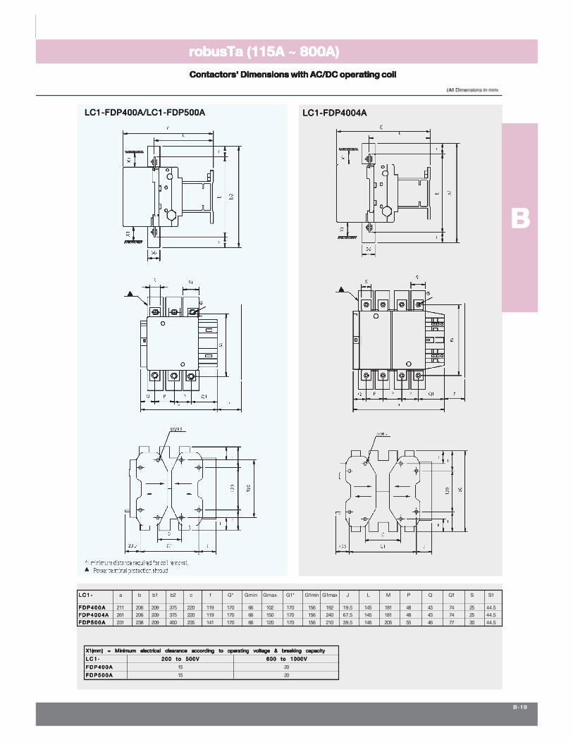
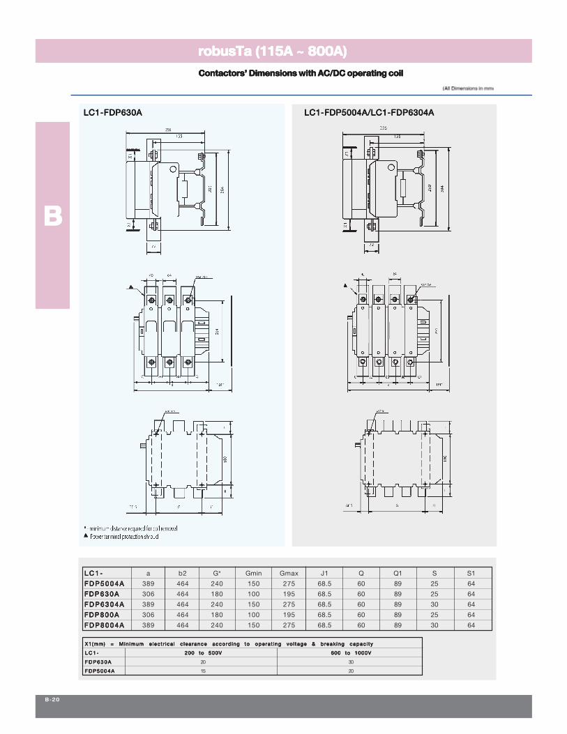
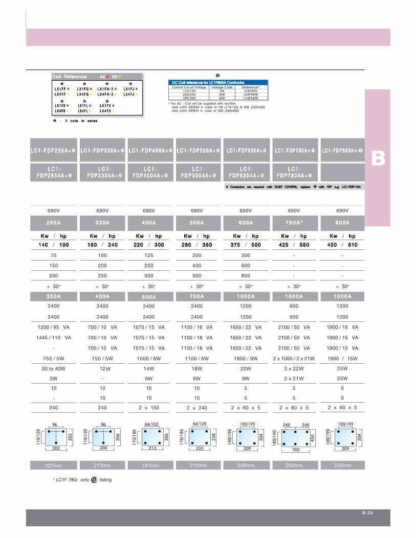
TYPE (LC1-F)TYPE (LC1-F)TYPE (LC1-F)TYPE (LC1-F)TYPE (LC1-F) U N I TU N I TU N I TU N I TU N I T 115A 150A 185A 225A 265A 330A 400A 500A 630A 780A 800A
Rated control circuit voltage (Uc) 50 or 60 Hz V 24...600 48...600 48...600 110...500 48...600
Control voltage limits Operational 0.85 - 1.10Uc 0.85-1.10Uc 0.85-1.10Uc 0.85-1.10Uc 0.85-1.10Uc
Temperature θθθθθ<55oC Drop out 0.35 - 0.55Uc 0.3-0 .5Uc 0.25-0.5Uc 0.2-0.4Uc 0.25-0.5Uc
Average consumption at 20 oC
and at Uc, 50/60 Hz coil Operational
Average consumption at 20 oC In rush 50 Hz coil VA 550 550 805 805 1200 700 1075 1100 1650 2100 1900
and at Uc, AC 50 / 60hz In rush 60 Hz coil VA 660 660 970 970 1445 700 1075 1100 1650 2100 1900
In rush 40 - 400 Hz coil VA - - - - 700 700 1075 1100 1650 2100 1900
In rush Cosφ 0.28 0.28 0.3 0.3 0.9 0.9 0.9 0.9 0.9 0.9 0.9
Sealed 50 Hz coil VA 45 45 55 55 95 10 15 18 22 50 15
Sealed 60 Hz coil VA 55 55 66 66 110 10 15 18 22 50 15
Sealed 40 - 400 Hz coil VA - - - - 10 10 15 18 22 50 22
Sealed Cosf 0.28 0.28 0.3 0.3 0.9 0.9 0.9 0.9 0.9 0.9 0.9
Average operating time at Uc Closing time “C” msec 23-35 23-35 20-35 20-35 30-65 30-65 40-75 40-75 40-80 40-80 40-80
Opening time “O” msec 5-15 5-15 7-15 7-15 100-170 100-170 100-170 100-170 100-200 130-230 100-200
Mechanical life Uc (Mechanical 50 or 60 Hz coil Cycles 10 10 10 10 10 10 10 10 5 5 5
durability) in millions of 50/60 Hz coil Cycles 10 10 10 10 10 10 10 10 5 5 5
operating cycles
Maximum operating rate In operating cycle/hour 2400 2400 2400 2400 2400 2400 2400 2400 1200 600 1200
Tightening Torque Power Circuit Connection Nm 1.2 1.2 1.2 1.2 1.2 1.2 1.2 1.2 1.2 1.2 1.2
C a b l i n gC a b l i n gC a b l i n gC a b l i n gC a b l i n g Minimum / Maximum C.S.A
Flexible Cable without cable end 1or 2 Conductors Sqmm 1/4 1/4 1/4 1/4 1/4 1/4 1/4 1/4 1/4 1/4 1/4
Flexible Cable with end 1 Conductor Sqmm 1/4 1/4 1/4 1/4 1/4 1/4 1/4 1/4 1/4 1/4 1/4
Flexible Cable wiht end 2 Conductors Sqmm 1/2.5 1/2.5 1/2.5 1/2.5 1/2.5 1/2.5 1/2.5 1/2.5 1/2.5 1/2.5 1/2.5
Solid Cable without cable end 1 or 2 Conductors Sqmm 1/4 1/4 1/4 1/4 1/4 1/4 1/4 1/4 1/4 1/4 1/4
φ
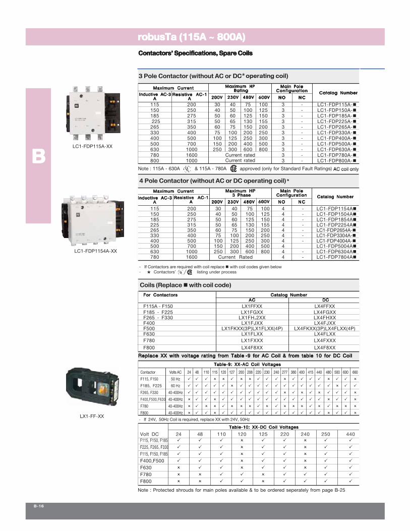
200V200V200V200V200V 230V230V230V230V230V 480V480V480V480V480V 600V600V600V600V600V N CN CN CN CN CN ON ON ON ON O
Catalog NumberCatalog NumberCatalog NumberCatalog NumberCatalog Number
Maximum HPMaximum HPMaximum HPMaximum HPMaximum HP Rating Rating Rating Rating Rating
200V200V200V200V200V 230V230V230V230V230V 480V480V480V480V480V 600V600V600V600V600V N CN CN CN CN C
Main PoleMain PoleMain PoleMain PoleMain PoleConfigurat ionConfigurat ionConfigurat ionConfigurat ionConfigurat ion
N ON ON ON ON O
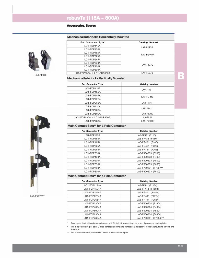
LA9-FG970
LA9-FJ970
LA9-FL970
LA9-FF4F
LA9-FJ4J
LA9-FF970
LA9-FG4G
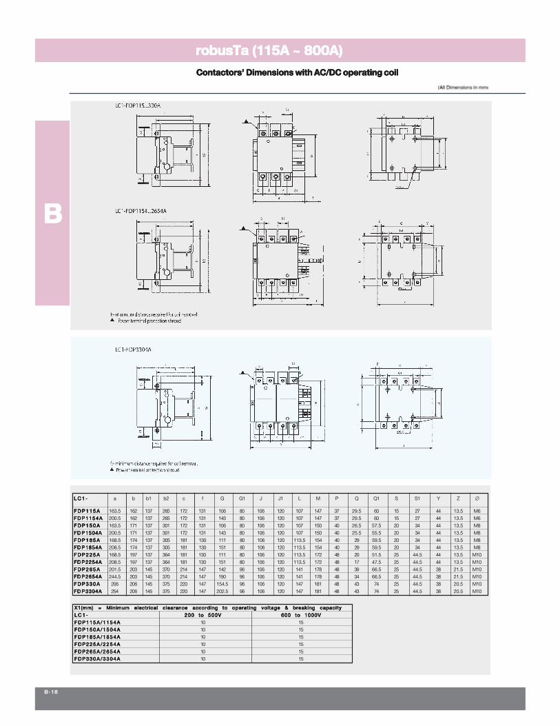
∅
c
256
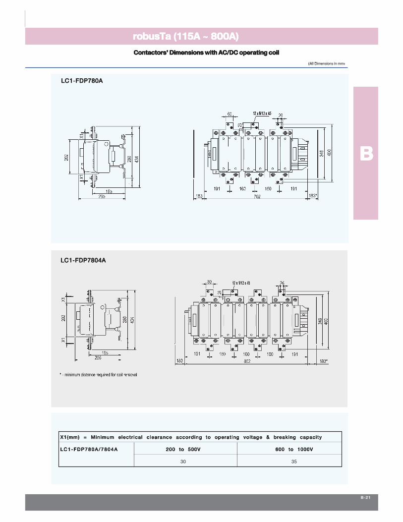
LC1-FDP780ALC1-FDP780ALC1-FDP780ALC1-FDP780ALC1-FDP780A
----------
DDDDD DDDDD DDDDD DDDDD
--------
DDDDD DDDDD DDDDD
80
110/
120
164
162
80
110/
120
164
162
110/
120
169
80
174
169
110/
120
80
197
θθθθθ
(θ
+++++
233
170/
180
238
66/120
180/
190
309
304
100/19596
110/
120
202
203
96
206
110/
120
206
702
240 240
180/
190
434
213
170/
180
66/102
206
+++++
Control Circuit Voltage Voltage Code Reference*110/120 FW LX4F8FW220/240 MW LX4F8MW380/400 Q W LX4F8QW
* For AC - Coil will be supplied with rectifier add suffix DRTE4U in case of FW (110/120) & MW (220/240) add suffix DRTE4S in case of QW (380/400)
DC Coil reference for LC1F800A ContactorDC Coil reference for LC1F800A ContactorDC Coil reference for LC1F800A ContactorDC Coil reference for LC1F800A ContactorDC Coil reference for LC1F800A Contactor
L X 1 F KL X 1 F KL X 1 F KL X 1 F KL X 1 F K L X 1 F LL X 1 F LL X 1 F LL X 1 F LL X 1 F LL X 4 F KL X 4 F KL X 4 F KL X 4 F KL X 4 F K L X 4 F LL X 4 F LL X 4 F LL X 4 F LL X 4 F L
-
180/
190
309
304
100/195
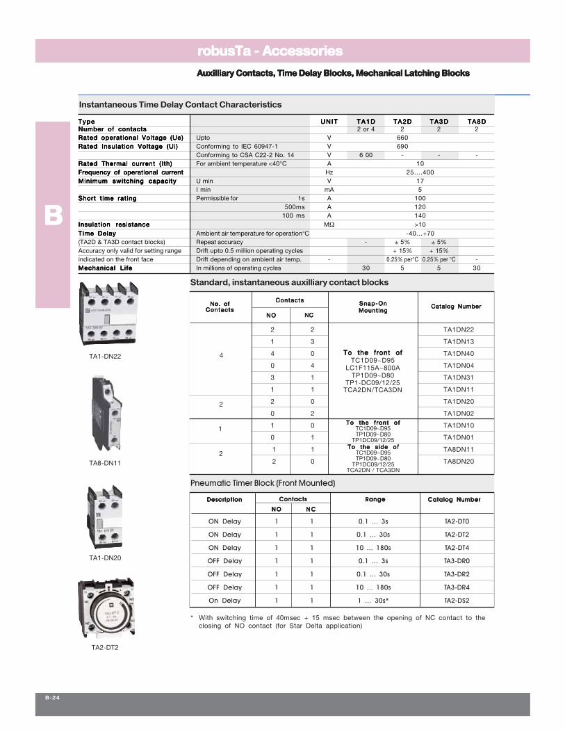
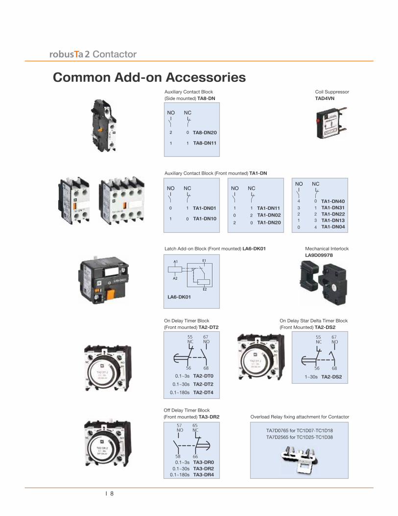
Pneumatic Timer Block (Front Mounted)
Descript ionDescript ionDescript ionDescript ionDescript ion Catalog NumberCatalog NumberCatalog NumberCatalog NumberCatalog Number
ON Delay 1 1 0.1 ... 3s TA2-DT0
ON Delay 1 1 0.1 ... 30s TA2-DT2
ON Delay 1 1 10 ... 180s TA2-DT4
OFF Delay 1 1 0.1 ... 3s TA3-DR0
OFF Delay 1 1 0.1 ... 30s TA3-DR2
OFF Delay 1 1 10 ... 180s TA3-DR4
On Delay 1 1 1 ... 30s* TA2-DS2
RangeRangeRangeRangeRangeContactsContactsContactsContactsContacts
N ON ON ON ON O N CN CN CN CN C
Ω
0 -
φφφφφ
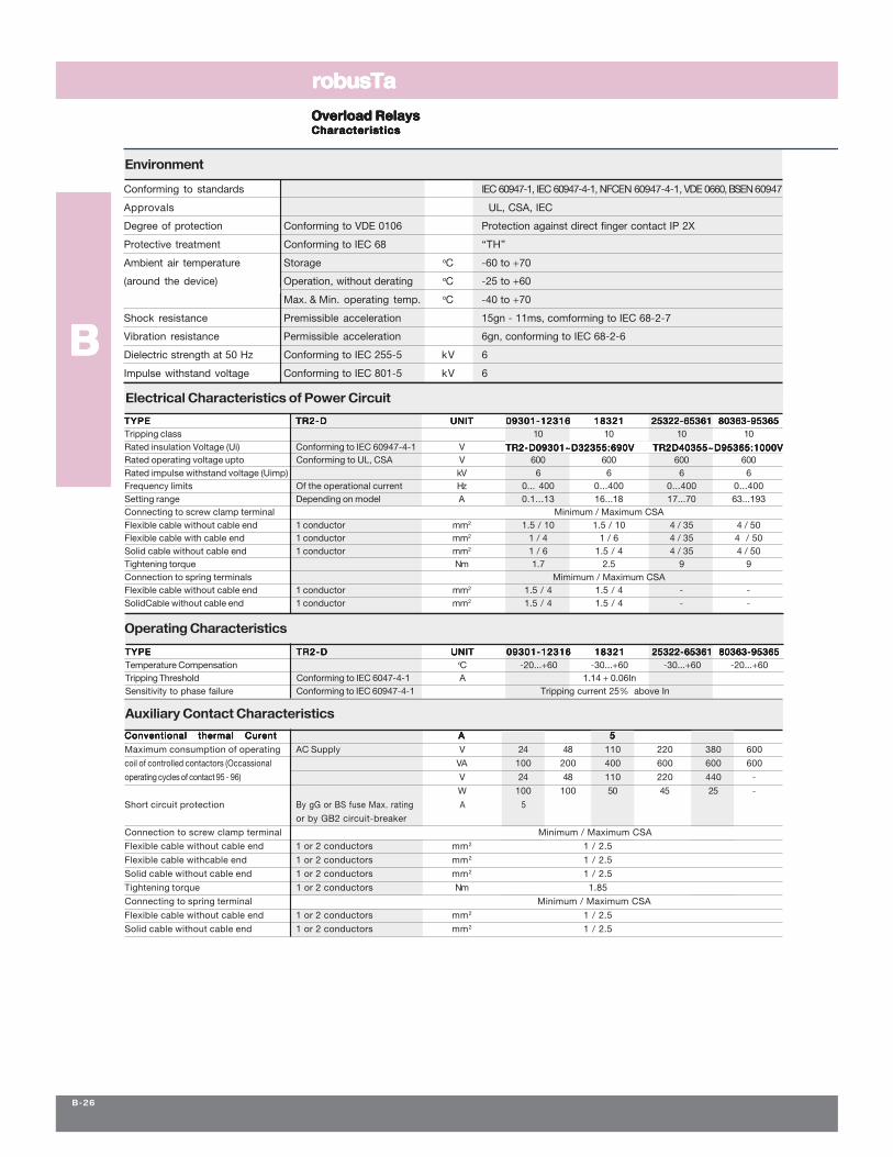
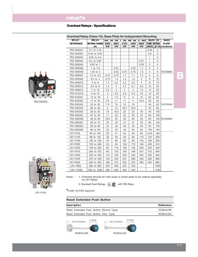
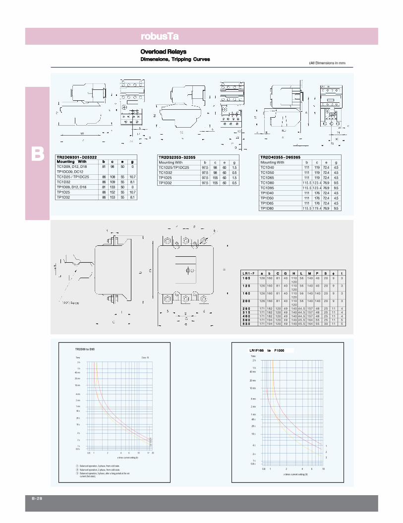
LR1F(M)105 to F1000
2 s
0.8 s
1 s
10 s
4 s
20 s
1 mn
40 s
2 mn
4 mn
10 mn
20 mn
40 mn
1 h
2 h
Time
0.8
2
3
1
x times current setting (lr)
1 2 4 6 10
Balanced operation, 3-phase, after a long period at the setcurrent (hot state).
Balanced operation, 2-phase, from cold state.
Balanced operation, 3-phase, from cold state.
x times current setting (lr)
2
3
1
20 mn
10 mn
4 mn
2 mn
1 mn
40 s
20 s
10 s
0.8 s
0.8
2 s
1 s
1
4 s
2 4
Time
40 mn
2 h
1 h
106 17
3
2
1
20
Class 10
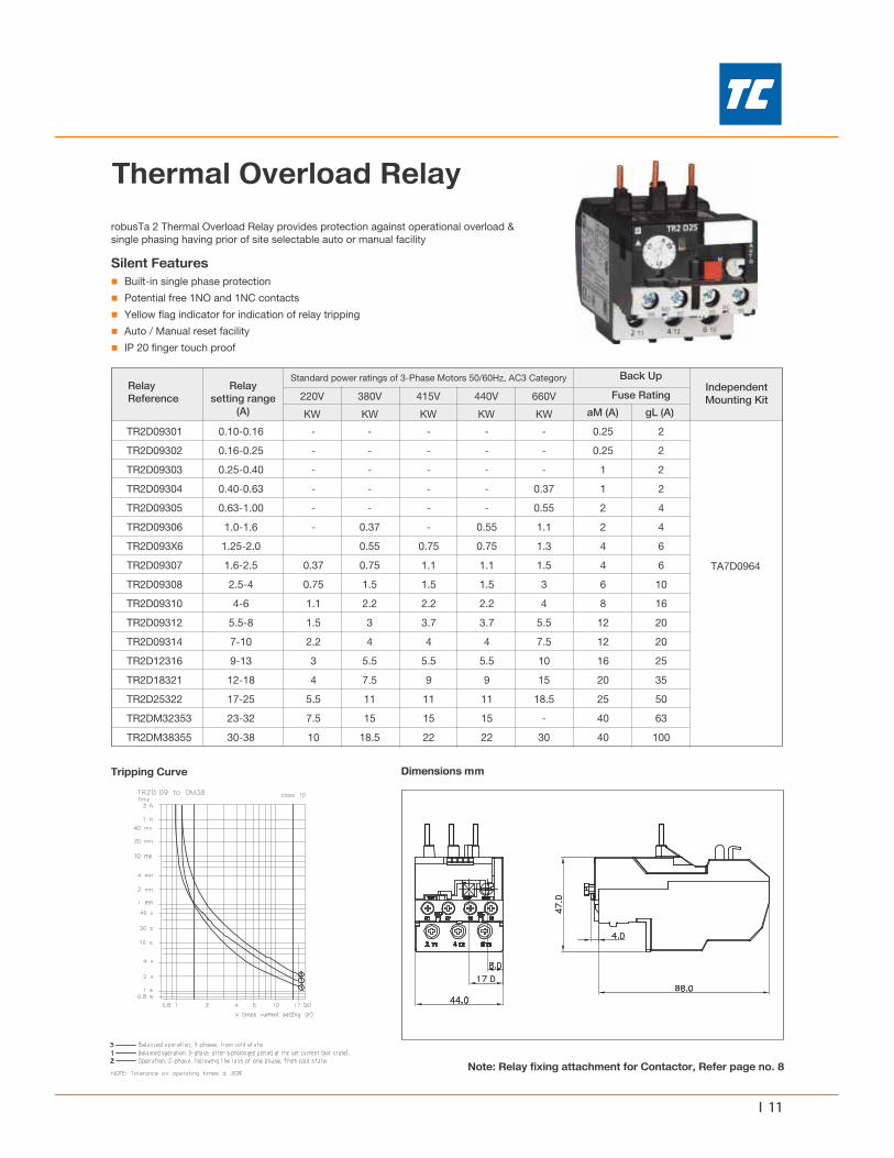
TR2D09 to D95
θθθθθ
TC Electric Controls LLC
E N E R G I Z I N G Y O U R W O R L D
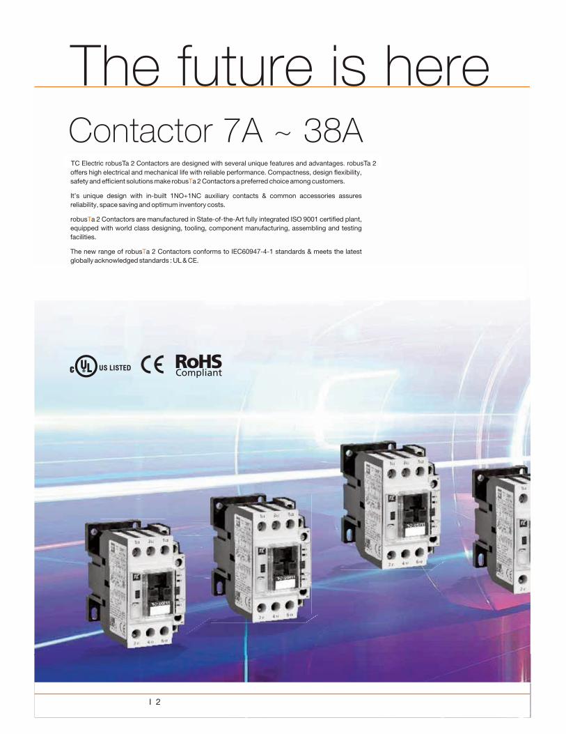
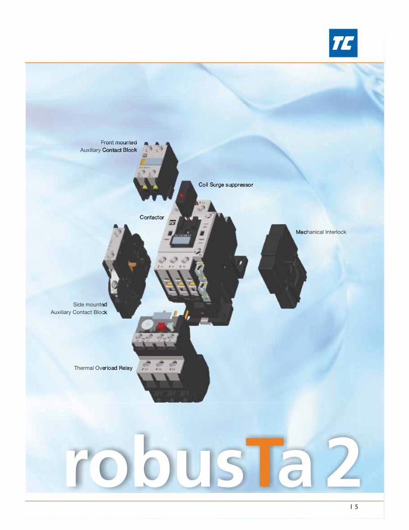
TC Electric robusTa 2 Contactors are designed with several unique features and advantages. robusTa 2

TC Electric Controls guaranteed coordination.
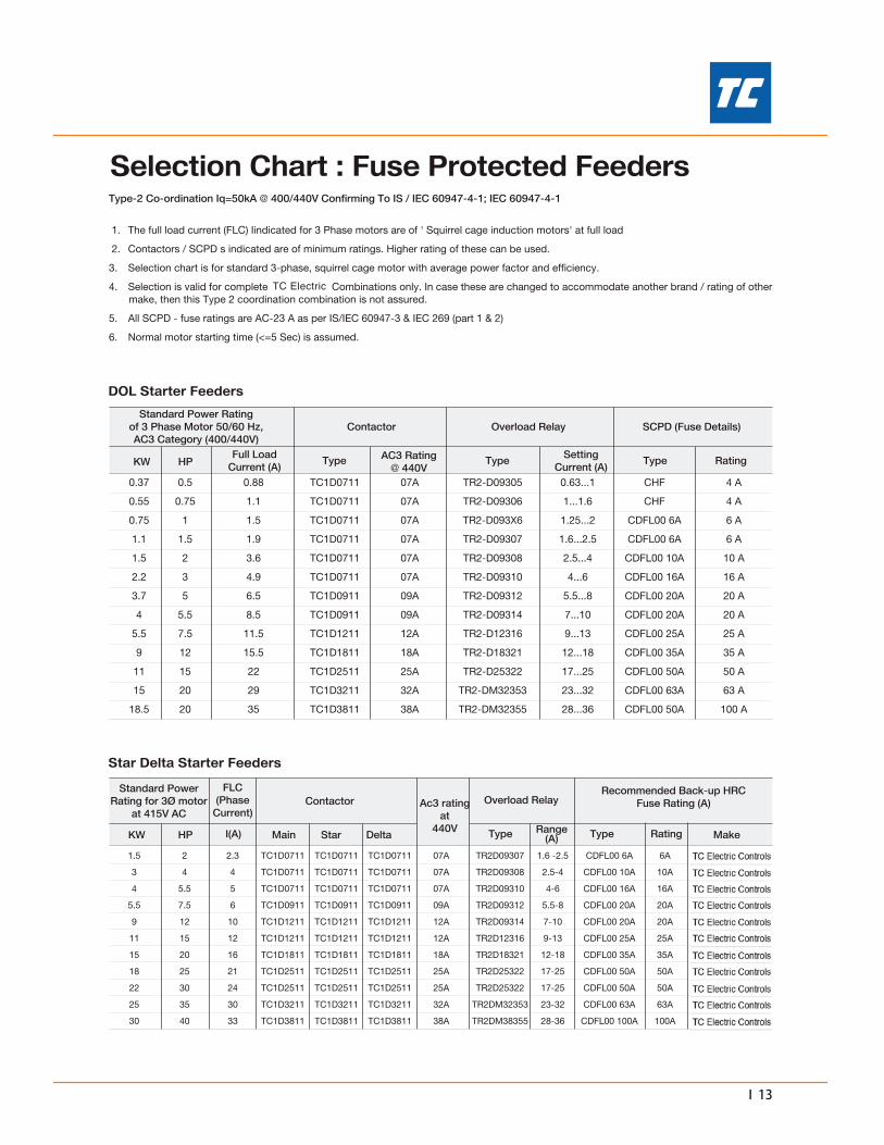
TC Electric
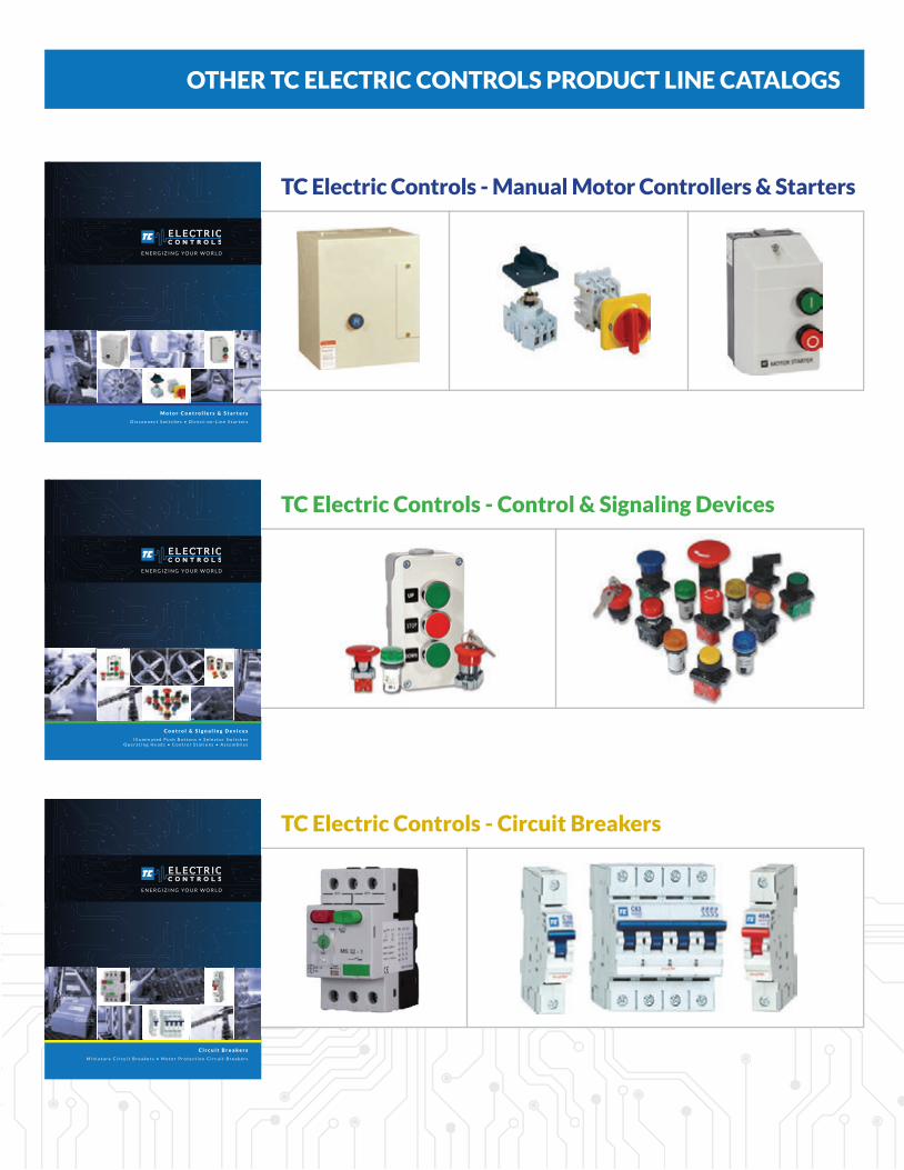
OTHER TC ELECTRIC CONTROLS PRODUCT LINE CATALOGS
E N E R G I Z I N G Y O U R W O R L D
C i r c u i t B r e a k e r s
M i n i a t u r e C i r c u i t B r e a k e r s • M o t o r P r o t e c t i o n C i r c u i t B r e a k e r s
TC Electric Controls - Circuit Breakers
E N E R G I Z I N G Y O U R W O R L D
C o n t r o l & S i g n a l i n g D e v i c e s
I l l u m i n a t e d P u s h B u t t o n s • S e l e c t o r S w i t c h e sO p e r a t i n g H e a d s • C o n t r o l S t a t i o n s • A s s e m b l i e s
TC Electric Controls - Control & Signaling Devices
E N E R G I Z I N G Y O U R W O R L D
M o t o r C o n t r o l l e r s & S t a r t e r s
D i s c o n n e c t S w i t c h e s • D i r e c t - o n - L i n e S t a r t e r s
TC Electric Controls - Manual Motor Controllers & Starters
TC Electric Controls Catalog Cover Contact and Overloads v1 no spreads.indd 3 1/12/2017 1:02:59 PM

1 3 2 0 To w e r R o a d , S c h a u m b u r g , I L 6 0 1 7 3
P h : ( 8 4 7 ) 5 9 8 - 3 5 5 0 • F a x : ( 8 4 7 ) 5 9 8 - 3 5 0 9w w w . t c e l e c t r i c c o n t r o l s . c o m
TC Electric Controls Catalog Cover Contact and Overloads v1 no spreads.indd 4 1/12/2017 1:02:59 PM
Related Documents