Energi Savr NodeTM 0-10V / SoftSwitch® Installation Guide Lutron® | 1 Energi Savr NodeTM 0-10 V / SoftSwitch® | Installation Guide Control Panel Ratings Control Power: 120-277 V 50/60 Hz 0.5 A Load Inputs: 120-277 V 50/60 Hz Output: 0-10 V: 50 mA sink per zone (QSN-4T16-S only) SoftSwitch: 120-277 V 16 A per output 0.5 HP @ 120 V 1.5 HP @ 277 V Operating environment: 32 ˚F to 104 ˚F (0 ˚C to 40 ˚C) Maximum humidity: 90% non-condensing Thermal dissipation: 40 BTU/hr Input Groups: 20 V 65 mA per group QS link: 24 V 14 PDU (Power Draw Units) 432 mA Model number overview QSN-4T16-S (Energi Savr Node for 0-10 V) QSN-4S16-S (SoftSwitch Energi Savr Node) QSN: Energi Savr Node 4T: 4 output zones, 0-10 V fixture controller 4S: 4 output zones, SoftSwitch 16: 16 A switched outputs S: Surface mount Please read this guide before installing. Contents Page Ratings and Model number overview .................................... 1 Product overview.................................................................. 2 Wiring overview.................................................................... 2 Mounting .............................................................................. 3 Control power wiring ............................................................ 3 Load wiring .......................................................................... 4 Input wiring .......................................................................... 6 Contact closure inputs .......................................................... 7 QS link wiring ....................................................................... 8 Applications ....................................................................... 10 Out of box functionality....................................................... 10 Normal operation................................................................ 11 QS link input(s) setup ......................................................... 11 Troubleshooting .................................................................. 11 Warranty ............................................................................ 12 Contact information ............................................................ 12 System Example Programming Guide available at : www.lutron.com/softswitchenergisavrnode QS link Control Power 120-277 V 4 Load Input Feeds 120-277 V 4 0-10 V Channels (QSN-4T16-S only) Emergency Contact Closure Input Contact Closure Input 4 Switched Load Outputs (16 A SoftSwitch 120-277 V ) Wireless Communication Wired Daylight Sensors (up to 4) 2 Wired Daylight Sensors (up to 4) 1,2 Wired Occupancy Sensors (up to 4) Wired Occupancy Sensors (up to 4) 1 Wired Wallstation or IR receivers (up to 4) Wired Wallstation or IR Receivers (up to 4) 1 NEC® Class 2/PELV Dry Contact Switch (up to 4) (by others) IR Transmitter IR Transmitter Notes: 1 Up to 4 wired sensors total (of any type). 2 The maximum number of daylight sensors (wired and wireless) that an Energi Savr Node unit can support is four (1 per zone). QSM (new!) seeTouch® QS Wallstation ESN Programming Interface Radio Powr SavrTM Occupancy Sensor (up to 10 per QSM) Radio Powr SavrTM Daylight Sensor (up to 10 per QSM) 2 Pico® Wireless Controller (up to 10 per QSM)

Welcome message from author
This document is posted to help you gain knowledge. Please leave a comment to let me know what you think about it! Share it to your friends and learn new things together.
Transcript

Energi Savr NodeTM 0-10V / SoftSwitch® Installation Guide Lutron® | 1
Energi Savr NodeTM 0-10 V / SoftSwitch® | Installation Guide
Control Panel RatingsControl Power: 120-277 V 50/60 Hz 0.5 ALoad Inputs: 120-277 V 50/60 HzOutput: 0-10 V: 50 mA sink per zone (QSN-4T16-S only) SoftSwitch: 120-277 V 16 A per output
0.5 HP @ 120 V 1.5 HP @ 277 V
Operating environment: 32 ˚F to 104 ˚F (0 ˚C to 40 ˚C)Maximum humidity: 90% non-condensingThermal dissipation: 40 BTU/hrInput Groups: 20 V 65 mA per groupQS link: 24 V 14 PDU (Power Draw Units) 432 mA
Model number overviewQSN-4T16-S (Energi Savr Node for 0-10 V)QSN-4S16-S (SoftSwitch Energi Savr Node)QSN: Energi Savr Node4T: 4 output zones, 0-10 V fixture controller4S: 4 output zones, SoftSwitch16: 16 A switched outputsS: Surface mount
Please read this guide before installing.
Contents PageRatings and Model number overview ....................................1
Product overview..................................................................2
Wiring overview....................................................................2
Mounting ..............................................................................3
Control power wiring ............................................................3
Load wiring ..........................................................................4
Input wiring ..........................................................................6
Contact closure inputs ..........................................................7
QS link wiring .......................................................................8
Applications .......................................................................10
Out of box functionality .......................................................10
Normal operation ................................................................11
QS link input(s) setup .........................................................11
Troubleshooting ..................................................................11
Warranty ............................................................................12
Contact information ............................................................12
System Example
Programming Guide available at : www.lutron.com/softswitchenergisavrnode
QS link
Control Power120-277 V
4 Load Input Feeds
120-277 V
4 0-10 V Channels(QSN-4T16-S only)
Emergency Contact Closure
Input
Contact Closure Input
4 Switched Load Outputs (16 A SoftSwitch 120-277 V )
Wireless Communication
Wired Daylight Sensors (up to 4)2
Wired Daylight Sensors (up to 4)1,2
Wired Occupancy Sensors (up to 4)
Wired Occupancy Sensors (up to 4)1
Wired Wallstation or IR receivers (up to 4)
Wired Wallstation or IR Receivers (up to 4)1
NEC® Class 2/PELV Dry Contact Switch (up to 4) (by others)
IR Transmitter
IR Transmitter
Notes: 1 Up to 4 wired sensors total (of any type).2 The maximum number of daylight sensors (wired and wireless) that an
Energi Savr Node unit can support is four (1 per zone).
QSM (new!)seeTouch® QS Wallstation
ESN Programming Interface
Radio Powr SavrTM Occupancy Sensor (up to 10 per QSM)
Radio Powr SavrTM Daylight Sensor (up to 10 per QSM)2
Pico® Wireless Controller (up to 10 per QSM)
Energi Savr NodeTM 0-10V / SoftSwitch® Installation GuideLutron® | 2
Energi Savr NodeTM 0-10 V / SoftSwitch® | Installation Guide
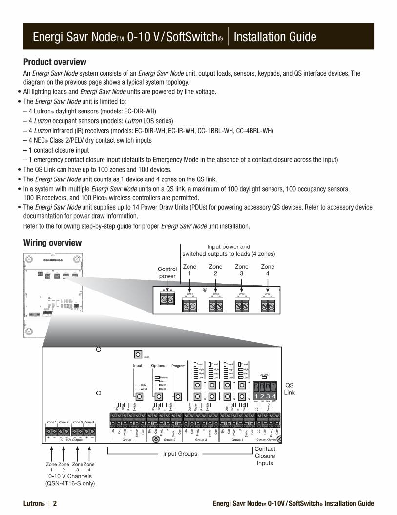
Product overviewAn Energi Savr Node system consists of an Energi Savr Node unit, output loads, sensors, keypads, and QS interface devices. The diagram on the previous page shows a typical system topology.
•AlllightingloadsandEnergi Savr Node units are powered by line voltage.•TheEnergi Savr Node unit is limited to: – 4 Lutron® daylight sensors (models: EC-DIR-WH) – 4 Lutron occupant sensors (models: Lutron LOS series) – 4 Lutron infrared (IR) receivers (models: EC-DIR-WH, EC-IR-WH, CC-1BRL-WH, CC-4BRL-WH) – 4 NEC® Class 2/PELV dry contact switch inputs – 1 contact closure input – 1 emergency contact closure input (defaults to Emergency Mode in the absence of a contact closure across the input)•TheQSLinkcanhaveupto100zonesand100devices.•TheEnergi Savr Node unit counts as 1 device and 4 zones on the QS link.•InasystemwithmultipleEnergi Savr Node units on a QS link, a maximum of 100 daylight sensors, 100 occupancy sensors,
100 IR receivers, and 100 Pico® wireless controllers are permitted.•TheEnergi Savr Node unit supplies up to 14 Power Draw Units (PDUs) for powering accessory QS devices. Refer to accessory device
documentation for power draw information.
Refer to the following step-by-step guide for proper Energi Savr Node unit installation.
Wiring overview
QS Link
Contact Closure Inputs
0-10 V Channels(QSN-4T16-S only)
Input Groups
Control power
Input power and switched outputs to loads (4 zones)
Zone 1
Zone 2
Zone 3
Zone 4
Zone 1
Zone 2
Zone 3
Zone 4
Energi Savr NodeTM 0-10V / SoftSwitch® Installation Guide Lutron® | 3
Energi Savr NodeTM 0-10 V / SoftSwitch® | Installation Guide
Step-by-step installation instructions
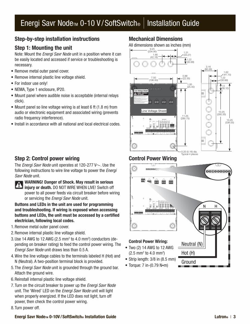
Step 1: Mounting the unitNote: Mount the Energi Savr Node unit in a position where it can be easily located and accessed if service or troubleshooting is necessary.
•Removemetalouterpanelcover.•Removeinternalplasticlinevoltageshield.•Forindooruseonly!•NEMA,Type1enclosure,IP20.•Mountpanelwhereaudiblenoiseisacceptable(internalrelays
click).•Mountpanelsolinevoltagewiringisatleast6ft(1.8m)from
audio or electronic equipment and associated wiring (prevents radio frequency interference).
•Installinaccordancewithallnationalandlocalelectricalcodes.
Mechanical DimensionsAll dimensions shown as inches (mm)
Control Power Wiring
11.25 (285.75)
10.25 (260.35)
0.20 (5.16) dia.Typical 4 places
1.00 (25.40) 1.5
(38.10)
1.22 (30.99)
1.66 (42.16)
1.31 (33.27)
0.88 (22.35) 1.22
(30.99)
1.62 (41.15)
9.25 (234.95)
7.50 (190.50)
3.16 (80.26)
13.25 (336.55)
Step 2: Control power wiringThe Energi Savr Node unit operates at 120-277 V . Use the following instructions to wire line voltage to power the Energi Savr Node unit.
WARNING! Danger of Shock. May result in serious injury or death.DONOTWIREWHENLIVE!Switchoffpower to all power feeds via circuit breaker before wiring or servicing the Energi Savr Node unit.
Buttons and LEDs in the unit are used for programming and troubleshooting. If wiring is exposed when accessing buttons and LEDs, the unit must be accessed by a certified electrician, following local codes.
1. Remove metal outer panel cover.2. Remove internal plastic line voltage shield.3. Use 14 AWG to 12 AWG (2.5 mm2 to 4.0 mm2) conductors (de-
pending on breaker rating) to feed the control power wiring. The Energi Savr Node unit draws less than 0.5 A.
4. Wire the line voltage cables to the terminals labeled H (Hot) and N (Neutral). A two-position terminal block is provided.
5. The Energi Savr Node unit is grounded through the ground bar. Attach the ground wire.
6. Reinstall internal plastic line voltage shield.7. Turn on the circuit breaker to power up the Energi Savr Node
unit. The ‘Wired’ LED on the Energi Savr Node unit will light when properly energized. If the LED does not light, turn off power, then check the control power wiring.
8. Turn power off.
Control Power Wiring:•Two(2)14AWGto12AWG
(2.5 mm2 to 4.0 mm2)•Striplength:3/8in(8.5mm)•Torque:7in-(0.79N•m)
Neutral (N)
Hot (H)
Ground
Line Voltage Shield
Energi Savr NodeTM 0-10V / SoftSwitch® Installation GuideLutron® | 4
Energi Savr NodeTM 0-10 V / SoftSwitch® | Installation Guide
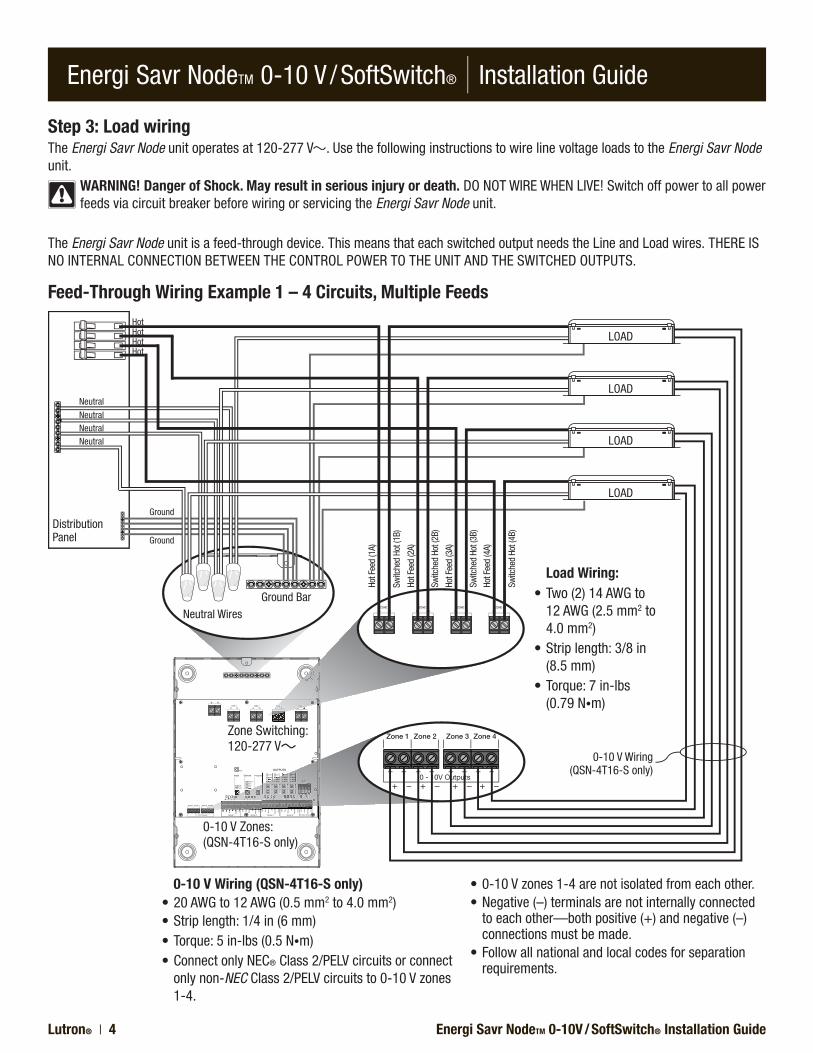
Step 3: Load wiringThe Energi Savr Node unit operates at 120-277 V . Use the following instructions to wire line voltage loads to the Energi Savr Node unit.
WARNING! Danger of Shock. May result in serious injury or death.DONOTWIREWHENLIVE!Switchoffpowertoallpowerfeeds via circuit breaker before wiring or servicing the Energi Savr Node unit.
The Energi Savr Node unit is a feed-through device. This means that each switched output needs the Line and Load wires. THERE IS NO INTERNAL CONNECTION BETWEEN THE CONTROL POWER TO THE UNIT AND THE SWITCHED OUTPUTS.
Zone Switching:120-277 V
0-10 V Zones:(QSN-4T16-S only)
Feed-Through Wiring Example 1 – 4 Circuits, Multiple Feeds
Switc
hed
Hot (
1B)
Hot F
eed
(1A)
Hot F
eed
(2A)
Hot F
eed
(3A)
Hot F
eed
(4A)
Switc
hed
Hot (
2B)
Switc
hed
Hot (
3B)
Switc
hed
Hot (
4B)
Ground BarNeutral Wires
Distribution Panel
LOAD
LOAD
LOAD
LOAD
0-10 V Wiring (QSN-4T16-S only)•20AWGto12AWG(0.5mm2 to 4.0 mm2)•Striplength:1/4in(6mm)•Torque:5in-lbs (0.5 N•m)•Connect only NEC® Class 2/PELV circuits or connect
only non-NEC Class 2/PELV circuits to 0-10 V zones 1-4.
•0-10Vzones1-4arenotisolatedfromeachother.•Negative(–)terminalsarenotinternallyconnected
to each other—both positive (+) and negative (–) connections must be made.
•Followallnationalandlocalcodesforseparationrequirements.
Load Wiring:•Two(2)14AWGto
12 AWG (2.5 mm2 to 4.0 mm2)
•Striplength:3/8in(8.5 mm)
•Torque:7in-lbs (0.79 N•m)
0-10 V Wiring(QSN-4T16-S only)
HotHotHotHot
Neutral
NeutralNeutralNeutral
Ground
Ground
Energi Savr NodeTM 0-10V / SoftSwitch® Installation Guide Lutron® | 5
Energi Savr NodeTM 0-10 V / SoftSwitch® | Installation Guide
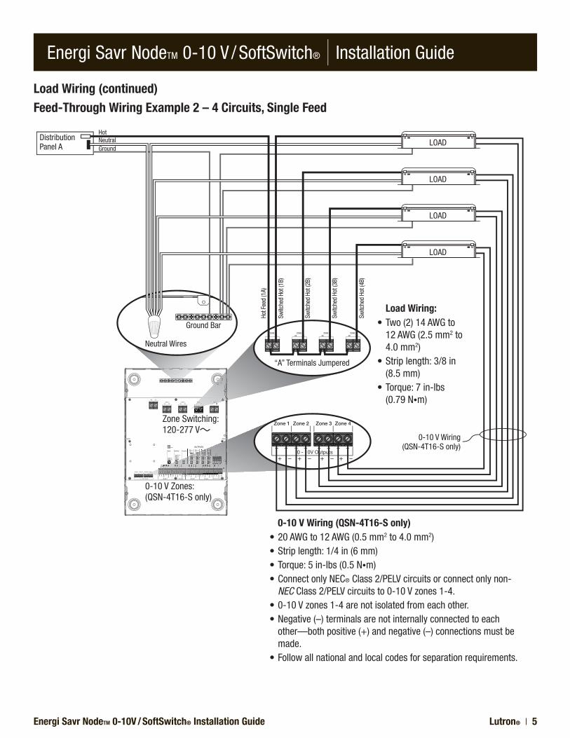
Load Wiring (continued)Feed-Through Wiring Example 2 – 4 Circuits, Single Feed
Zone Switching:120-277 V
0-10 V Zones:(QSN-4T16-S only)
HotNeutralGround
Ground Bar
“A” Terminals Jumpered
Neutral Wires
Distribution Panel A LOAD
LOAD
LOAD
LOAD
0-10 V Wiring (QSN-4T16-S only)•20AWGto12AWG(0.5mm2 to 4.0 mm2)•Striplength:1/4in(6mm)•Torque:5in-lbs(0.5N•m)•ConnectonlyNEC® Class 2/PELV circuits or connect only non-
NEC Class 2/PELV circuits to 0-10 V zones 1-4.•0-10Vzones1-4arenotisolatedfromeachother.•Negative(–)terminalsarenotinternallyconnectedtoeach
other—both positive (+) and negative (–) connections must be made.
•Followallnationalandlocalcodesforseparationrequirements.
Load Wiring:•Two(2)14AWGto
12 AWG (2.5 mm2 to 4.0 mm2)
•Striplength:3/8in(8.5 mm)
•Torque:7in-lbs (0.79 N•m)
0-10 V Wiring(QSN-4T16-S only)
Switc
hed
Hot (
1B)
Hot F
eed
(1A)
Switc
hed
Hot (
2B)
Switc
hed
Hot (
3B)
Switc
hed
Hot (
4B)

Energi Savr NodeTM 0-10V / SoftSwitch® Installation GuideLutron® | 6
Energi Savr NodeTM 0-10 V / SoftSwitch® | Installation Guide
Occupancy Sensor
IR Transmitter IR Transmitter
Daylight/IR Sensor*
Note: Maximum wire run length to each input not to exceed 150 ft (46 m).
IR Receiver*or Wired
Wallstation*
NEC Class 2 Dry Contact
Switch
Red
Blac
k
Yello
w
Blue
Blac
k
Red
Red
Blac
k
Whi
te*
Whi
te*
20 V – 20 V
Occ – Occupancy Sensor
Photo – Daylight Sensor
IR – IR Receiver*
Switch – NEC Class 2/PELV Switch
Com – Common
LUTRONR
LUTRON
LUTRONR
Step 4: Input group wiringTo connect a daylight sensor, occupancy sensor, infrared (IR) receiver, and/or NEC® Class 2/PELV dry contact switch, refer to the instruction sheets provided with the devices. Diagrams for the input terminals are shown below.
WARNING! Danger of Shock. May result in serious injury or death.DONOTWIREWHENLIVE!Switchoffpowertoallpowerfeeds via circuit breaker before wiring or servicing the Energi Savr Node unit.
Buttons and LEDs in the unit are used for programming and troubleshooting. If line voltage shield is removed, the unit must be accessed by a certified electrician, following local codes.
Note: The Energi Savr Node unit accepts only one IR input (either daylight/IR sensor or IR receiver) per group.
Input Group Wiring:•20AWGto12AWG
(0.5 mm2 to 4.0 mm2)•Striplength:1/4in(6mm)•Torque:5in-lbs(0.5N•m)
NOTE: There are four input groups. Each group has the same inputs as shown in the diagram below.
Input Group Wiring
* Note: Only one IR device may be connected per input. If the IR signal from a daylight sensor is connected, a wall control may not be connected to the same input, and vice-versa.
Line Voltage Shield

Energi Savr NodeTM 0-10V / SoftSwitch® Installation Guide Lutron® | 7
Energi Savr NodeTM 0-10 V / SoftSwitch® | Installation Guide
Step 5: Contact Closure Inputs: Emergency and CCI
WARNING! Danger of Shock. May result in serious injury or death.DONOTWIREWHENLIVE!Switchoffpower to all power feeds via circuit breaker before wiring or servicing the Energi Savr Node unit.
If line voltage shield is removed, the unit must be accessed by a certified electrician, following local codes.
•BothContactClosureInputs’(EmergencyandCCI)wiringisNEC® Class 2/PELV. Follow all applicable national and local codes for proper circuit separation and protection.
•CCIinputmustbeusedwithdrycontactclosuredevices.
•IftheEmergencyinputisopen,theEnergi Savr Node unit will enter Emergency Mode, which will turn on all loads and disable local zone control and control from sensors and QS devices.
Note: The Energi Savr Node unit will default to Emergency Mode if the Emergency input is left open. If no Emergency contact input is required, please leave the wire jumper in the Emergency input terminals.
Contact Closure Wiring
CCI – CONTACT CLOSURE INPUT COM – COMMON
COM – COMMON EMERG – EMERGENCY
Contact Closure Wiring:•20AWGto12AWG
(0.5 mm2 to 4.0 mm2)•Striplength:1/4in(6mm)•Torque:5in-lbs(0.5N•m)
Line Voltage Shield

Energi Savr NodeTM 0-10V / SoftSwitch® Installation GuideLutron® | 8
Energi Savr NodeTM 0-10 V / SoftSwitch® | Installation Guide
Step 6: QS link wiringWARNING! Danger of Shock. May result in serious injury or death.DONOTWIREWHENLIVE!Switchoffpower to all power feeds via circuit breaker before wiring or servicing the Energi Savr Node unit.
Buttons and LEDs in the unit are used for programming and troubleshooting. If line voltage shield is removed, the unit must be accessed by a certified electrician, following local codes.
QS link communication uses NEC® Class 2/PELV wiring. Follow all local and national electrical codes when installing NEC Class 2/PELV wiring with line voltage wiring.
The total distance of the QS link wiring must not exceed 2000 ft (610 m). QS Link Wiring Distance Wire Gauge
Available from Lutron in one cable:
Less than 500 ft (125 m)
Power (terminals 1 and 2): 1 pair 18 AWG (1.0 mm2)
GRX-CBL-346SData (terminals 3 and 4): 1 pair 22 AWG (0.5 mm2), twisted and shielded*
500 ft (125 m) to 2000 ft (610 m)
Power (terminals 1 and 2): 1 pair 12 AWG (4.0 mm2)
GRX-CBL-46LData (terminals 3 and 4): 1 pair 22 AWG (0.5 mm2), twisted and shielded*
* Alternate Data-only cable: Use approved data link cable (22 AWG (0.5 mm2) twisted/shielded) from Belden, model #9461.
Check for compatibility in your area.
A QS system can have up to 100 zones and 100 devices. The Energi Savr Node unit counts as 1 device and up to 4 zones.
See diagram on the right for QS link wiring. 1. Connect terminals 1, 3 and 4 to all Energi Savr Node units. 2. Each Energi Savr Node unit has its own built-in power supply. 3. The terminal 2 connection (24 V ) supplies power to QS de-
vices sharing that connection. – Ensure that QS devices powered from terminal 2 of the Energi
Savr Node unit do not consume a combined total of more than 14 Power Draw Units (PDUs).
– Refer to the documentation for each QS device to determine that device’s PDU consumption.
NOTE: To connect extra QS devices, use a separate power supply (24 V ), and only connect COM, MUX, and MUX to the devices connected to the Energi Savr Node unit.
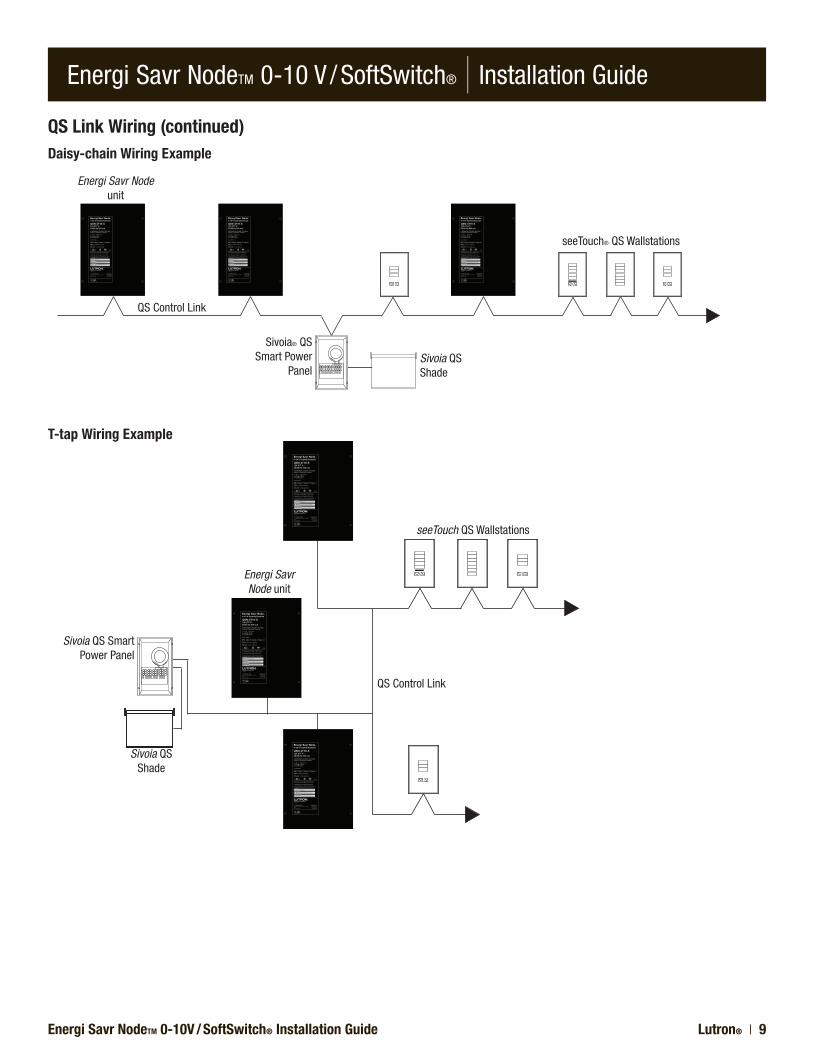
4. Wiring may be daisy chained or t-tapped.
Power draw calculations are not needed for wireless sensors or sensors connected directly to the Energi Savr Node units.
(4) MUX(3) MUX(2) 24 V(1) COM
QS Link Wiring:•22AWGto12AWG
(0.5 mm2 to 4.0 mm2)•Striplength:3/8in(8.5mm)•Torque:5in-lbs(0.5N•m)
12 AWG (4.0 mm2)
18 AWG (1.0 mm2)
QS Link Wiring
NEC Class 2/PELV Terminal Connections
Each low-voltage NEC Class 2/PELV terminal can accept only two 18 AWG (1.0 mm2) wires. Two 12 AWG (4.0 mm2) conduc-tors will not fit. Connect as shown below using appropriate wire connectors.
Line Voltage Shield
Energi Savr NodeTM 0-10V / SoftSwitch® Installation Guide Lutron® | 9
Energi Savr NodeTM 0-10 V / SoftSwitch® | Installation Guide
Energi Savr Node unit
Sivoia QS Shade
Sivoia® QS Smart Power
Panel
seeTouch® QS Wallstations
QS Control Link
Sivoia QS Smart Power Panel
Sivoia QS Shade
seeTouch QS Wallstations
Energi Savr Node unit
QS Control Link
QS Link Wiring (continued)Daisy-chain Wiring Example
T-tap Wiring Example
Energi Savr NodeTM 0-10V / SoftSwitch® Installation GuideLutron® | 10
Energi Savr NodeTM 0-10 V / SoftSwitch® | Installation Guide
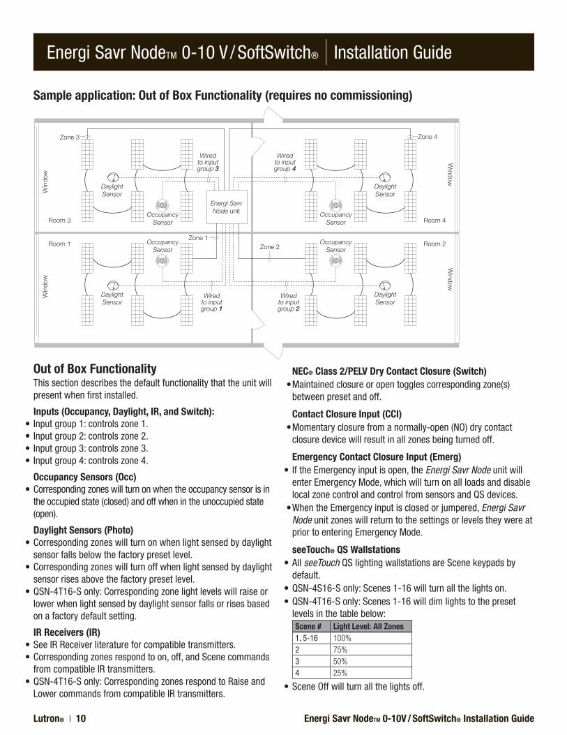
Sample application: Out of Box Functionality (requires no commissioning)
Daylight Sensor
Daylight Sensor
Daylight Sensor
Daylight Sensor
Zone 3
Zone 1Zone 2
Zone 4
Room 3 Room 4
Room 1 Room 2
Win
dow
Window
Win
dow
Window
Occupancy Sensor
Occupancy Sensor
Occupancy Sensor
Occupancy Sensor
Energi Savr Node unit
Wired to input group 3
Wired to input group 4
Wired to input group 1
Wired to input group 2
Out of Box FunctionalityThis section describes the default functionality that the unit will present when first installed.
Inputs (Occupancy, Daylight, IR, and Switch):• Input group 1: controls zone 1.• Input group 2: controls zone 2.• Input group 3: controls zone 3.• Input group 4: controls zone 4.
Occupancy Sensors (Occ)•Correspondingzones will turn on when the occupancy sensor is in
the occupied state (closed) and off when in the unoccupied state (open).
Daylight Sensors (Photo)•Correspondingzones will turn on when light sensed by daylight
sensor falls below the factory preset level.•Correspondingzones will turn off when light sensed by daylight
sensor rises above the factory preset level.•QSN-4T16-S only: Corresponding zone light levels will raise or
lower when light sensed by daylight sensor falls or rises based on a factory default setting.
IR Receivers (IR)•See IR Receiver literature for compatible transmitters.•Correspondingzones respond to on, off, and Scene commands
from compatible IR transmitters.•QSN-4T16-S only: Corresponding zones respond to Raise and
Lower commands from compatible IR transmitters.
NEC® Class 2/PELV Dry Contact Closure (Switch)•Maintainedclosureoropentogglescorrespondingzone(s)
between preset and off.
Contact Closure Input (CCI)•Momentaryclosurefromanormally-open(NO)drycontact
closure device will result in all zones being turned off.
Emergency Contact Closure Input (Emerg)•IftheEmergencyinputisopen,theEnergi Savr Node unit will
enter Emergency Mode, which will turn on all loads and disable local zone control and control from sensors and QS devices.
•WhentheEmergencyinputisclosedorjumpered,Energi Savr Node unit zones will return to the settings or levels they were at prior to entering Emergency Mode.
seeTouch® QS Wallstations•AllseeTouch QS lighting wallstations are Scene keypads by
default.•QSN-4S16-Sonly:Scenes1-16willturnallthelightson.•QSN-4T16-Sonly:Scenes1-16willdimlightstothepreset
levels in the table below:Scene # Light Level: All Zones1, 5-16 100%2 75%3 50%4 25%
•SceneOffwillturnallthelightsoff.
Energi Savr NodeTM 0-10V / SoftSwitch® Installation Guide Lutron® | 11
Energi Savr NodeTM 0-10 V / SoftSwitch® | Installation Guide
Normal OperationIn normal operation, the following buttons allow the user to ac-cess certain basic functions:
1. (Raise) — QSN-4T16-S: Raises zone light level in 1% incre-ments from 0-100%.
— QSN-4S16-S: Turns selected zone on.2. (Lower) — QSN-4T16-S: Decreases zone light level in 1%
decrements from 100-0%. — QSN-4S16-S: Turns selected zone off.
Note: On QSN-4T16-S only - For any zone, simultaneously pressing and holding the and buttons will toggle the zone between high end and low end.
QS Link Input(s) SetupseeTouch QS Wallstation or GRAFIK Eye® QS unit - Scenes and Scenes + OffAssigns a seeTouch QS Wallstation or GRAFIK Eye QS unit to any Energi Savr Node unit zone on the QS link.
1. To assign a seeTouch QS Wallstation or GRAFIK Eye QS unit to an Energi Savr Node unit(s), simultaneously press and hold the top and bottom buttons on the wallstation or GRAFIK Eye QS unit for 3 seconds. The QS link enters Programming Mode. The sensor LEDs on the Energi Savr Node unit(s) will flash sequen-tially through each input and group.
2. To assign or un-assign desired zone(s) to a wallstation, simul-taneously press and hold the the and buttons for the desired zone. A blinking ‘Zone’ LED indicates an assigned zone.
3. To exit Programming Mode, simultaneously press and hold the the top and bottom buttons on the wallstation or GRAFIK Eye QS unit for 3 seconds.
Note: For more advanced programming information, refer to the online Programming Guide at: www.lutron.com/softswitchenergisavrnode
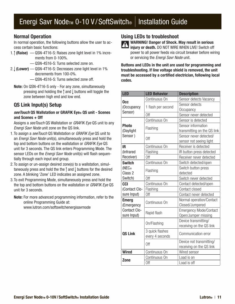
Using LEDs to troubleshootWARNING! Danger of Shock. May result in serious injury or death.DONOTWIREWHENLIVE!Switchoffpower to all power feeds via circuit breaker before wiring or servicing the Energi Savr Node unit.
Buttons and LEDs in the unit are used for programming and troubleshooting. If line voltage shield is removed, the unit must be accessed by a certified electrician, following local codes.
LED LED Behavior Description
Occ (Occupancy Sensor)
Continuous On Sensor detects Vacancy
1 flash per secondSensor detects Occupancy
Off Sensor never detected
Photo (Daylight Sensor )
Continuous On Sensor is detected
FlashingSensor information transmitting on the QS link
OffSensor never detected/sensor not seeing light
IR (Infrared Receiver)
Continuous On Receiver is detectedFlashing IR button press detectedOff Receiver never detected
Switch (NEC® Class 2 Switch)
Continuous On Switch detected/open
FlashingSwitch button press detected
Off Switch never detectedCCI (Contact Clo-sure Input)
Continuous On Contact detected/openFlashing Contact closedOff Contact never detected
Emerg (Emergency Contact Clo-sure Input)
Continuous OnNormal operation/Contact Closed/Jumpered
Rapid flashEmergency Mode/Contact Open/Jumper missing
QS Link
On/FlashingDevice transmitting/ receiving on the QS link
3 quick flashes every 4 seconds
Communication error
OffDevice not transmitting/receiving on the QS link
Wired Continuous On Wired sensor
ZoneContinuous On Load is onOff Load is off
Energi Savr NodeTM 0-10V / SoftSwitch® Installation GuideLutron® | 12
Energi Savr NodeTM 0-10 V / SoftSwitch® | Installation Guide
Lutron Electronics Co., Inc.One year limited warranty
For a period of one year from the date of purchase, and subject to the exclusions and restrictions described below, Lutron warrants each new unit to be free from manufacturing defects. Lutron will, at its option, either repair the defective unit or issue a credit equal to the purchase price of the defective unit to the Customer against the purchase price of comparable replacement part purchased from Lutron. Replacements for the unit provided by Lutron or, at its sole discretion, an approved vendor may be new, used, repaired, reconditioned, and/or made by a different manufacturer.
If the unit is commissioned by Lutron or a Lutron approved third party as part of a Lutron commissioned lighting control system, the term of this warranty will be extended, and any credits against the cost of replacement parts will be prorated, in accordance with the warranty issued with the commissioned system, except that the term of the unit’s warranty term will be measured from the date of its commissioning.
EXCLUSIONS AND RESTRICTIONS This Warranty does not cover, and Lutron and its suppliers are not responsible for:1. Damage, malfunction or inoperability diagnosed by Lutron or a Lutron approved third party as caused by
normal wear and tear, abuse, misuse, incorrect installation, neglect, accident, interference or environmental factors, such as (a) use of incorrect line voltages, fuses or circuit breakers; (b) failure to install, maintain and operate the unit pursuant to the operating instructions provided by Lutron and the applicable provisions of the National Electrical Code and of the Safety Standards of Underwriter’s Laboratories; (c) use of incompatible devices or accessories; (d) improper or insufficient ventilation; (e) unauthorized repairs or adjustments; (f) vandalism; or (g) an act of God, such as fire, lightning, flooding, tornado, earthquake, hurricane or other problems beyond Lutron’s control.
2. On-site labor costs to diagnose issues with, and to remove, repair, replace, adjust, reinstall and/or reprogram the unit or any of its components.
3. Equipment and parts external to the unit, including those sold or supplied by Lutron (which may be covered by a separate warranty).
4. The cost of repairing or replacing other property that is damaged when the unit does not work properly, even if the damage was caused by the unit.
EXCEPT AS EXPRESSLY PROVIDED IN THIS WARRANTY, THERE ARE NO EXPRESS OR IMPLIED WARRANTIES OF ANY TYPE, INCLUDING ANY IMPLIED WARRANTIES OF FITNESS FOR A PARTICULAR PURPOSE OR MERCHANTABILITY. LUTRON DOES NOT WARRANT THAT THE UNIT WILL OPERATE WITHOUT INTERRUPTION OR BE ERROR FREE.
NO LUTRON AGENT, EMPLOYEE OR REPRESENTATIVE HAS ANY AUTHORITY TO BIND LUTRON TO ANY AFFIRMATION, REPRESENTATION OR WARRANTY CONCERNING THE UNIT. UNLESS AN AFFIRMATION, REPRESENTATION OR WARRANTY MADE BY AN AGENT, EMPLOYEE OR REPRESENTATIVE IS SPECIFICALLY INCLUDED HEREIN, OR IN STANDARD PRINTED MATERIALS PROVIDED BY LUTRON, IT DOES NOT FORM A PART OF THE BASIS OF ANY BARGAIN BETWEEN LUTRON AND CUSTOMER AND WILL NOT IN ANY WAY BE ENFORCEABLE BY CUSTOMER.
IN NO EVENT WILL LUTRON OR ANY OTHER PARTY BE LIABLE FOR EXEMPLARY, CONSEQUENTIAL, INCIDENTAL OR SPECIAL DAMAGES (INCLUDING, BUT NOT LIMITED TO, DAMAGES FOR LOSS OF PROFITS, CONFIDENTIAL OR OTHER INFORMATION, OR PRIVACY; BUSINESS INTERRUPTION; PERSONAL INJURY; FAILURE TO MEET ANY DUTY, INCLUDING OF GOOD FAITH OR OF REASONABLE CARE; NEGLIGENCE, OR ANY OTHER PECUNIARY OR OTHER LOSS WHATSOEVER), NOR FOR ANY REPAIR WORK UNDERTAKEN WITHOUT LUTRON’S WRITTEN CONSENT ARISING OUT OF OR IN ANY WAY RELATED TO THE INSTALLATION, DEINSTALLATION, USE OF OR INABILITY TO USE THE UNIT OR OTHERWISE UNDER OR IN CONNECTION WITH ANY PROVISION OF THIS WARRANTY, OR ANY AGREEMENT INCORPORATING THIS WARRANTY, EVEN IN THE EVENT OF THE FAULT, TORT (INCLUDING NEGLIGENCE), STRICT LIABILITY, BREACH OF CONTRACT OR BREACH OF WARRANTY OF LUTRON OR ANY SUPPLIER, AND EVEN IF LUTRON OR ANY OTHER PARTY WAS ADVISED OF THE POSSIBILITY OF SUCH DAMAGES.
NOTWITHSTANDING ANY DAMAGES THAT CUSTOMER MIGHT INCUR FOR ANY REASON WHATSOEVER (INCLUDING, WITHOUT LIMITATION, ALL DIRECT DAMAGES AND ALL DAMAGES LISTED ABOVE), THE ENTIRE LIABILITY OF LUTRON AND OF ALL OTHER PARTIES UNDER THIS WARRANTY ON ANY CLAIM FOR DAMAGES ARISING OUT OF OR IN CONNECTION WITH THE MANUFACTURE, SALE, INSTALLATION, DELIVERY, USE, REPAIR, OR REPLACEMENT OF THE UNIT, OR ANY AGREEMENT INCORPORATING THIS WARRANTY, AND CUSTOMER’S SOLE REMEDY FOR THE FOREGOING, WILL BE LIMITED TO THE AMOUNT PAID TO LUTRON BY CUSTOMER FOR THE UNIT. THE FOREGOING LIMITATIONS, EXCLUSIONS AND DISCLAIMERS WILL APPLY TO THE MAXIMUM EXTENT ALLOWED BY APPLICABLE LAW, EVEN IF ANY REMEDY FAILS ITS ESSENTIAL PURPOSE.
TO MAKE A WARRANTY CLAIMTo make a warranty claim, promptly notify Lutron within the warranty period described above by calling the Lutron Technical Support Center at (800) 523-9466. Lutron, in its sole discretion, will determine what action, if any, is required under this warranty. To better enable Lutron to address a warranty claim, have the unit’s serial and model numbers available when making the call. If Lutron, in its sole discretion, determines that an on-site visit or other remedial action is necessary, Lutron may send a Lutron Services Co. representative or coordinate the dispatch of a representative from a Lutron approved vendor to Customer’s site, and/or coordinate a warranty service call between Customer and a Lutron approved vendor. This warranty gives you specific legal rights, and you may also have other rights which vary from state to state. Some states do not allow limitations on how long an implied warranty lasts, so the above limitation may not apply to you. Some states do not allow the exclusion or limitation of incidental or consequential damages, so the above limitation or exclusion may not apply to you.
Contact Information
Internet: www.lutron.com
World headquartersLutron Electronics Co., Inc.7200 Suter Road, Coopersburg, PA18036-1299 USATEL +1.610.282.3800FAX +1.610.282.1243Technical Support 1.800.523.9466Toll-Free 1.888.LUTRON1
European headquartersUnited KingdomLutron EA Ltd.6 Sovereign Close, London, E1W3JF UKTEL +44.(0)20.7702.0657FAX +44.(0)20.7480.6899Technical support+44.(0)20.7680.4481FREEPHONE 0800.282.107
Asian headquartersSingaporeLutron GL Ltd.15 Hoe Chiang Road,#07-03 Euro Asia Centre,Singapore 089316TEL +65.6220.4666FAX +65.6220.4333
Technical hotlinesFrance: 0800.90.12.18Germany: 00800.5887.6635Italy: 800.979.208Spain: 900.948.944Northern China: 10.800.712.1536Southern China: 10.800.120.1536Hong Kong: 800.901.849Singapore: 800.120.4491Taiwan: 00.801.137.737Thailand: 001.800.120.665853Other Areas in Asia: +65.6220.4666
Made and printed in the USAP/N 032-316 Rev. C 06/2010
Lutron, GRAFIK Eye, Pico, seeTouch, SoftSwitch, and Sivoia are registered trademarks and Energi Savr Node and Radio Powr Savr are trademarks of Lutron Electronics Co., Inc.
NEC is a registered trademark of National Fire Protection Association, Quincy, Massachusetts.
© 2010 Lutron Electronics Co, Inc.
Related Documents