A MINI PROJECT REPORT ON ENDUSER ACCUSATION Submitted to JAWAHARLAL NEHRU TECHNOLOGICAL UNIVERSITY In the partial fulfillment for the award of the degree of BACHELOR OF TECHNOLOGY IN INFORMATION TECHNOLOGY Done by M.SIRISHA : 08UU1A1228 A.PRADEEP : 08UU1A1243 K.SAI DEEKSHITH : 08UU1A1224 Under the esteemed guidance of Mr.N.VIJAYA SUNDER SAGAR Associate Professor, IT DEPT DEPARTMENT OF INFORMATION TECHNOLOGY VISWABHARATHI COLLEGE OF ENGINEERING JAWAHARLAL NEHRU TECHNOLOGICAL UNIVERSITY HYDERABAD - 1 -

Welcome message from author
This document is posted to help you gain knowledge. Please leave a comment to let me know what you think about it! Share it to your friends and learn new things together.
Transcript
8/2/2019 EndUser Accusation Documentation
http://slidepdf.com/reader/full/enduser-accusation-documentation 1/126
A MINI PROJECT REPORT
ON
ENDUSER ACCUSATION
Submitted to
JAWAHARLAL NEHRU TECHNOLOGICAL UNIVERSITY
In the partial fulfillment for the award of the degree of
BACHELOR OF TECHNOLOGY
IN
INFORMATION TECHNOLOGY
Done by
M.SIRISHA : 08UU1A1228
A.PRADEEP : 08UU1A1243
K.SAI DEEKSHITH : 08UU1A1224
Under the esteemed guidance of
Mr.N.VIJAYA SUNDER SAGAR Associate Professor, IT DEPT
DEPARTMENT OF INFORMATION TECHNOLOGY
VISWABHARATHI COLLEGE OF ENGINEERING
JAWAHARLAL NEHRU TECHNOLOGICAL UNIVERSITY
HYDERABAD
- 1
8/2/2019 EndUser Accusation Documentation
http://slidepdf.com/reader/full/enduser-accusation-documentation 2/126
VISWABHARATHI COLLEGE OF ENGINEERING
DEPARTMENT OF INFORMATION TECHNOLOGY
CERTIFICATE
This is to certify that mini project work entitle “ENDUSER ACCUSATION”
Is the bonafide work done by
M.SIRISHA : 08UU1A1228
A.PRADEEP : 08UU1A1243
K.SAI DEEKSHITH : 08UU1A1224
In the department of information technology, VISWABHARATHI COLLEGE OF ENGINEERING,
is submitted to JNTU Hyderabad in partial fulfillment of the requirements of
award of B.TECH degree in Information Technology
Mr.N.VIJAYA SUNDER SAGAR Mr.N.VIJAYA SUNDER SAGAR
Internal Guide HEAD OF THE DEPARTMENT
Dept of IT Dept of IT
VBCE,Kukatpally. VBCE,Kukatpally
INTERNAL EXAMINER EXTERNAL EXAMINER
- 2
8/2/2019 EndUser Accusation Documentation
http://slidepdf.com/reader/full/enduser-accusation-documentation 3/126
ACKNOWLEDGMENT
Our gratitude to Hnbl.Sri A.V.V Raju , chairman ,viswa bharathi college of engineering
for his accomplishing principles that guided us to complete our project more significantly.
We extend our thanks to Hnbl.smt..Bharathi ,Director Viswabharathi College o
Engineering for his magnificient devotion during the project.
We also extend our thanks to Mr.R.V.Krishniah , principal , Viswabharathi College o
Engineering for his magnificient devotion during the project.
We express our gratitude to Mr.N.Vijaya Sunder Sagar HOD,IT Dept. Viswabharath
College of Engineering for his valuable suggestions and advices through out the project.
We wish to place on our record deep sense of gratitude to our project guide,Mr
Mr.N.Vijaya Sunder Sagar,Assoc.Prof.IT Dept.Viswabharathi College of Engineering, for
his abundant support,patience and understanding through the project work.
We also extent our thanks to faculty members for their cooperation during our project.
M.SIRISHA : 08UU1A1228
A.PRADEEP : 08UU1A1243
K.SAI DEEKSHITH : 08UU1A1224
- 3

8/2/2019 EndUser Accusation Documentation
http://slidepdf.com/reader/full/enduser-accusation-documentation 4/126
ABSTRACT
- 4

8/2/2019 EndUser Accusation Documentation
http://slidepdf.com/reader/full/enduser-accusation-documentation 5/126
The End User Accusation is a web based project Take the complaints fromend users through online for electricity, municipality, gas, water . Byusing this, electricity , municipality, gas, water department can givebetter service to consumers.
End user Accusation is online complaint system, they have to maintaintheir User details, user creation details, in online. This project has toprovide online transactions means admin will collect the all thecomplaints and assign to the employees to solve their user problems andit has to maintain global database which provide permission to access
from anywhere.
The scope of this project is to develop a Web Based End user Accusation
is following helps organizations plan, execute and deliver on their entire
portfolio of projects.
End user Accusation is online complaint system, they have to maintain
their User details, user creation details, in online. This project has to
provide online transactions means admin will collect the all the
complaints and assign to the employees to solve their user problems and
it has to maintain global database which provide permission to access
from anywhere.
The scope of Software Requirements Specification is to present al
requirements about End user accusation System.
- 5
8/2/2019 EndUser Accusation Documentation
http://slidepdf.com/reader/full/enduser-accusation-documentation 6/126
CONTENTS
1. INTRODUCTION
1.1. INTRODUCTION TO PROJECT……………………………………………………………………………… 91.2. ORGANIZATION PROFILE ……………………………………………………………………………………101.3. PURPOSE OF THE PROJECT ………………………………………………………………………………….11
2. SYSTEM ANALYSIS
2.1. INTRODUCTION…………………………………………………………………………………………………….132.2. ANALYSIS MODEL 13
2.3. STUDY OF THE SYSTEM2.4. HARDWARE & SOFTWARE REQUIRMENT
2.5. PROBLEMS IN EXISTING STSTEM2.6. SOLUTION OF THESE PROBLEMS IN PROPOSED SYSTEM
2.7. INPUT & OUTPUT
3. FEASIBILITY REPORT
3.1. TECHNICAL FEASIBILITY3.2. OPERATIONAL FEASIBILITY3.3. ECONOMIC FEASIBILITY
4. SOFTWARE REQUIREMENT SPECIFICATIONS
4.1. FUNCIONAL REQUIREMENTS
4.2. NON-FUNCIONAL REQUIREMENTS
4.3. PERFORMANCE REQUIREMENTS
5. SYSTEM DEVELOPEMENT ENVIRONMENT
5.1. INTRODUCTION TO .NET FRAMEWORK5.2. ASP.NET5.3. C#.NET5.4. SQL SERVER
6. SYSTEM DESIGN6.1. INTRODUCTION6.2. NORMALIZATION6.3. DATA DICTIONARY6.4. E-R DIAGRAM6.5. DATA FLOW DIAGRAM
6.6. ACTIVITY DIAGRAM6.7. USE CASE DIAGRAM6.8. SEQUENCE DIAGRAM6.9. CLASS DIAGRAM6.10. COLLOBORATION DIAGRAM
7. OUTPUT SCREENS
8. SYSTEM TESTING AND IMPLEMENTATION
- 6

8/2/2019 EndUser Accusation Documentation
http://slidepdf.com/reader/full/enduser-accusation-documentation 7/126
8.1. INTRODUCTION
8.2. STRATEGIC APPROACH OF SOFTWARE TESTING
8.3. TESTING STRATEGIES8.4. TEST CASES
9. SYSTEM SECURITY
9.1. INTRODUCTION9.2. SECURITY IN SOFTWARE
10. CONCLUSION
11. FUTURE IMPROVEMENT
12. BIBLIOGRAPHY
- 7

8/2/2019 EndUser Accusation Documentation
http://slidepdf.com/reader/full/enduser-accusation-documentation 8/126
Chapter 1
INTRODUCTION
- 8

8/2/2019 EndUser Accusation Documentation
http://slidepdf.com/reader/full/enduser-accusation-documentation 9/126
1.1. INTRODUCTION TO PROJECT
The End User Accusation is a web based project Take the complaints from end users throughonline for electricity, municipality, gas, water . By using this, electricity , municipality, gas,water department can give better service to consumers.
End user Accusation is online complaint system, they have to maintain their User details,user creation details, in online. This project has to provide online transactions means adminwill collect the all the complaints and assign to the employees to solve their user problemsand it has to maintain global database which provide permission to access from anywhere.
- 9
8/2/2019 EndUser Accusation Documentation
http://slidepdf.com/reader/full/enduser-accusation-documentation 10/126
1.2. ORGANIZATION PROFILE
Datapoint Info Solutions (P) Ltd
S i m p l i f y i n g S o l u t I o n s & O p p o r t u n i t i e s
Business Proposition
Datapoint is incepted by young and ambitious team of Professional in the Industry with
the Idea & motto of “Simplifying Solutions & opportunities” . Datapoint is into IT Training(Corporate/Individual), Project assistance, Software Development and Placements. Datapoint is
one among the very few companies in Hyderabad, which are spread across all the areas and
technologies.
Datapoint has been actively in the profession of sourcing IT professionals from
the year 2001. We have since placed scores of candidates from different skill sets, with varying
levels of experience.
Datapoint started its journey initially as a Consulting Company and as a successfu
Placement Consultants as per the clients requirements we also emerged as a Corporate Training
Of-late we found that many engineering graduates are not being able to find jobs for themselves
despite increasing demand for IT professionals & Even our clients couldn’t able to find the
suitable and potential candidates even in the freshers.
At this crucial point we found the gap which needed to be filled by Datapoint to improve
our client satisfaction levels. The very decision of “Training (IT & Non-IT aspects) & providing Project assistance” to the freshers made Datapoint as a significant player in the
market. Datapoint is assisting many colleges and Organizations in Training & Recruiting freshers.
- 10
8/2/2019 EndUser Accusation Documentation
http://slidepdf.com/reader/full/enduser-accusation-documentation 11/126
PURPOSE OF THE PROJECT
The End User Accusation is online complaint system, they have to maintain their User details,
user creation details, in online. This project has to provide online transactions means admin will
collect the all the complaints and assign to the employees to solve their user problems and it
has to maintain global database which provide permission to access from anywhere.
- 11
8/2/2019 EndUser Accusation Documentation
http://slidepdf.com/reader/full/enduser-accusation-documentation 12/126
Chapter 2
SYSTEM ANALYSIS
- 12

8/2/2019 EndUser Accusation Documentation
http://slidepdf.com/reader/full/enduser-accusation-documentation 13/126
2.1. INTRODUCTION
After analyzing the requirements of the task to be performed, the next step is to analyze the
problem and understand its context. The first activity in the phase is studying the existing
system and other is to understand the requirements and domain of the new system. Both the
activities are equally important, but the first activity serves as a basis of giving the functiona
specifications and then successful design of the proposed system. Understanding the properties
and requirements of a new system is more difficult and requires creative thinking and
understanding of existing running system is also difficult, improper understanding of present
system can lead diversion from solution.
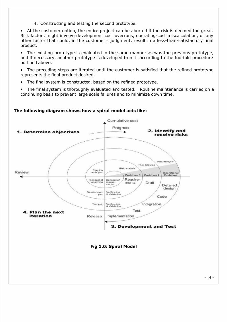
2.2. ANALYSIS MODEL
SPIRAL MODEL was defined by Barry Boehm in his 1988 article, “A spiral Model of Software
Development and Enhancement. This model was not the first model to discuss iterative
development, but it was the first model to explain why the iteration models.
As originally envisioned, the iterations were typically 6 months to 2 years long. Each phase startswith a design goal and ends with a client reviewing the progress thus far. Analysis and
engineering efforts are applied at each phase of the project, with an eye toward the end goal o
the project.
The steps for Spiral Model can be generalized as follows:
• The new system requirements are defined in as much details as possible. This usuallyinvolves interviewing a number of users representing all the external or internal users andother aspects of the existing system.
• A preliminary design is created for the new system.
• A first prototype of the new system is constructed from the preliminary design. This isusually a scaled-down system, and represents an approximation of the characteristics of thefinal product.
• A second prototype is evolved by a fourfold procedure:
1. Evaluating the first prototype in terms of its strengths, weakness, and risks.
2. Defining the requirements of the second prototype.
3. Planning a designing the second prototype.
- 13
8/2/2019 EndUser Accusation Documentation
http://slidepdf.com/reader/full/enduser-accusation-documentation 14/126
4. Constructing and testing the second prototype.
• At the customer option, the entire project can be aborted if the risk is deemed too greatRisk factors might involve development cost overruns, operating-cost miscalculation, or anyother factor that could, in the customer’s judgment, result in a less-than-satisfactory finaproduct.
• The existing prototype is evaluated in the same manner as was the previous prototype
and if necessary, another prototype is developed from it according to the fourfold procedureoutlined above.
• The preceding steps are iterated until the customer is satisfied that the refined prototyperepresents the final product desired.
• The final system is constructed, based on the refined prototype.
• The final system is thoroughly evaluated and tested. Routine maintenance is carried on acontinuing basis to prevent large scale failures and to minimize down time.
The following diagram shows how a spiral model acts like:
Fig 1.0: Spiral Model
- 14
8/2/2019 EndUser Accusation Documentation
http://slidepdf.com/reader/full/enduser-accusation-documentation 15/126
2.3. STUDY OF THE SYSTEM
In the flexibility of uses the interface has been developed a graphics concepts in mind
associated through a browser interface. The GUI’s at the top level has been categorized as
follows
1. Administrative User Interface Design
2. The Operational and Generic User Interface Design
The administrative user interface concentrates on the consistent information that is practically
part of the organizational activities and which needs proper authentication for the data collection
The Interface helps the administration with all the transactional states like data insertion, data
deletion, and data updating along with executive data search capabilities.
The operational and generic user interface helps the users upon the system in transactions
through the existing data and required services. The operational user interface also helps theordinary users in managing their own information helps the ordinary users in managing their own
information in a customized manner as per the assisted flexibilities.
NUMBER OF MODULES
The modules involved are:
1.Admin
2.Employee
3.Reports
4.Authentication
Administrator Module:
This module focuses on adding new users and line-men. Give unique id and password for
every one who will use this system. Assigning tasks to line-man and make them execute.
Employee Module :
This module focuses on viewing consumer complaints and checking which complaint is
assigned to employee. And give feed back to admin about complaints execution.
Reports(users) :
This module focuses on generating reports based on the time interval means from date to
to-date. View all complaints, verify complaint and complaints status. If any complaint not
executed then it will be re-assigned to another line man fro better service.
- 15

8/2/2019 EndUser Accusation Documentation
http://slidepdf.com/reader/full/enduser-accusation-documentation 16/126
Authentication:
Authentication is the module in which all the verification is done according to user details.
Here valid user only can access the website, or else he can’t.
2.4. HARDWARE & SOFTWARE SPECIFICATIONS
HARDWARE REQUIREMENTS:
• PIV 2.8 GHz Processor and Above
•
RAM 512MB and Above• HDD 10 GB Hard Disk Space and Above
SOFTWARE REQUIREMENTS:
• WINDOWS OS (XP / 2000 / 2000 Server / 2003 Server)
• Visual Studio .Net 2008/2010 Enterprise/Professional Edition
• Internet Information Server 5.0 (IIS)
• MS.Net Framework 3.5
• SQL Server 2005/2008 Enterprise Edition
2.5. PROBLEMS IN EXISTING STSTEM
The existing system is manual and the manual system works in the following way:
• Whenever the user wants to give the complaints in particular region, The complaint holdehas to approach in particular area and give the complaint has to be taken manually.
• The complaint, which is given by the user, is done manually that is received by the officerand hand it over to the some higher department. If any problem with that then again
- 16
8/2/2019 EndUser Accusation Documentation
http://slidepdf.com/reader/full/enduser-accusation-documentation 17/126
complaint holder has to approach that particular officer and do the same, this process isdone manually.
• The complaints which has to given by the user will be done manually.
• The consumer has to give complaint using hard copies.
Till now most companies has adopted the above manual system that produces lot of problems
and at the same time the following disadvantages are there with the above system.
The increasing complexity, producing the reports as desired is not possible, and protracted time
scales of modern systems design and development have made a complaints on Internet system
both essential and mandatory.
2.6. PROPOSED SYSTEM
To overcome all the difficulties of the existing system the management has proposed automated
the whole system and the development of the new automated system contains the following
activities, which try to automate the entire process keeping in view of the database integration
approach.
• It provides complete activity as automated system.• It is not limited to a single system because it is aimed to develop for web basedenvironment.•
User friendliness (Graphical User Interface) is provided in the application.• Provide Interactive interface through which a user can interact with different areas ofapplication easily.• The system makes the overall task much easier and flexible.• It can be accessed over the Internet/Intranet.• There is no risk of data mismanagement at any level while the project development isunder process.• Report generation feature is provided using ASP.Net Data Control like Grid View/DataList/Repeater/Form View to generate different kinds of reports easily.• It provides high level of security using Form Based Authentication.• It provides role based authentication to the different users like AdministratorEmployee, User (Non-Registered Users) etc.• Deploy the application on a single system and make is available on all the systemswithin the network, thereby reducing the maintenance cost of software.
2.6. INPUT AND OUTPUT
The major inputs and outputs and major functions of the system are follows:
Inputs:
- 17
8/2/2019 EndUser Accusation Documentation
http://slidepdf.com/reader/full/enduser-accusation-documentation 18/126
It is necessary to determine the various types of inputs. Inputs can be categorized as follows:
Admin enter his user id and password for login. User enters his user id and password fo
login. Admin enter user id or date for track the user login information New users give his
completed personnel, address and phone details for registration. Admin gives different kind of
user information for search the user data. User gives his user id, hint question, answer for
getting the forgotten password. User request for Municipal Bill.
Outputs:
Admin can have his own home page. Users enter their own home page. The user defined
data can store in the centralized database. Admin will get the login information of a particular
user. The new user’s data will be stored in the centralized database. Admin get the search details
of different criteria. User can get his forgot password. User can get the Bill Details
Chapter 3
- 18
8/2/2019 EndUser Accusation Documentation
http://slidepdf.com/reader/full/enduser-accusation-documentation 19/126
Feasibility Report
- 19
8/2/2019 EndUser Accusation Documentation
http://slidepdf.com/reader/full/enduser-accusation-documentation 20/126
Preliminary investigation examine project feasibility, the likelihood the system will be
useful to the organization. The main objective of the feasibility study is to test the Technical
Operational and Economical feasibility for adding new modules and debugging old running
system. All system is feasible if they are unlimited resources and infinite time. There are aspects
in the feasibility study portion of the preliminary investigation:
• Technical Feasibility
• Operation Feasibility
• Economical Feasibility
3.1. Technical Feasibility
The technical issue usually raised during the feasibility stage of the investigation includes
the following:
• Does the necessary technology exist to do what is suggested?
• Do the proposed equipments have the technical capacity to hold the data required to use
the new system?
• Will the proposed system provide adequate response to inquiries, regardless of the
number or location of users?
• Can the system be upgraded if developed?
• Are there technical guarantees of accuracy, reliability, ease of access and data security?
Earlier no system existed to cater to the needs of ‘Secure Infrastructure Implementation
System’. The current system developed is technically feasible. It is a web based user interface
for audit workflow at ABC Tech. Thus it provides an easy access to the users. The database’s
purpose is to create, establish and maintain a workflow among various entities in order to
facilitate all concerned users in their various capacities or roles. Permission to the users would be
granted based on the roles specified. Therefore, it provides the technical guarantee of accuracy
reliability and security. The software and hard requirements for the development of this projectare not many and are already available in-house at ABC Tech or are available as free as open
source. The work for the project is done with the current equipment and existing software
technology. Necessary bandwidth exists for providing a fast feedback to the users irrespective o
the number of users using the system.
3.2. Operational Feasibility
- 20
8/2/2019 EndUser Accusation Documentation
http://slidepdf.com/reader/full/enduser-accusation-documentation 21/126
Proposed projects are beneficial only if they can be turned out into information system
That will meet the organization’s operating requirements. Operational feasibility aspects of the
project are to be taken as an important part of the project implementation. Some of the
important issues raised are to test the operational feasibility of a project includes the following: -
•
Is there sufficient support for the management from the users?• Will the system be used and work properly if it is being developed and implemented?
• Will there be any resistance from the user that will undermine the possible application
benefits?
This system is targeted to be in accordance with the above-mentioned issues. Beforehand
the management issues and user requirements have been taken into consideration. So there is
no question of resistance from the users that can undermine the possible application benefits.
The well-planned design would ensure the optimal utilization of the computer resources and
would help in the improvement of performance status.
3.3. Economic Feasibility
A system can be developed technically and that will be used if installed must still be a good
investment for the organization. In the economical feasibility, the development cost in creating
the system is evaluated against the ultimate benefit derived from the new systems. Financia
benefits must equal or exceed the costs.
The system is economically feasible. It does not require any addition hardware osoftware. Since the interface for this system is developed using the existing resources and
technologies available at ABC Tech, There is nominal expenditure and economical feasibility for
certain.
- 21
8/2/2019 EndUser Accusation Documentation
http://slidepdf.com/reader/full/enduser-accusation-documentation 22/126
Chapter 4
SOFTWARE REQUIREMENT SPECIFICATION
INTRODUCTION
- 22
8/2/2019 EndUser Accusation Documentation
http://slidepdf.com/reader/full/enduser-accusation-documentation 23/126
This document is the complete product requirement specification for the End User Accusation
System. This is the only document that contains all information regarding the requirements
placed on the End User Accusation by the customer, catalogued in an unambiguous fashion
Unless otherwise stated, this document, and any future revisions of this document, supersedes
all other requirements documents that exist for the End User Accusation.
Purpose
The purpose of this Software Requirement Specification (SRS) is to help the project. If the user
wants to give a complaint then, user should register to the site and should login to the system.
After login to the system, user can post a complaint to the department. Admin will view all the
complaints in the department wise and assignment of the task to employees will be done.
Employees will rectify the problem of the customers.
Scope
The scope of this project is to develop a Web Based End user Accusation is following helps
organizations plan, execute and deliver on their entire portfolio of projects.
End user Accusation is online complaint system, they have to maintain their User details, user
creation details, in online. This project has to provide online transactions means admin will
collect the all the complaints and assign to the employees to solve their user problems and it
has to maintain global database which provide permission to access from anywhere.
The scope of Software Requirements Specification is to present all requirements about End user
accusation System.
DEVELOPERS RESPONSIBILITIES OVERVIEW:
The developer is responsible for:
Developing the system, which meets the SRS and solving all the requirements of the system?
• Demonstrating the system and installing the system at client's location after the
acceptance testing is successful.
• Submitting the required user manual describing the system interfaces to work on it and
also the documents of the system.
• Conducting any user training that might be needed for using the system.
- 23
8/2/2019 EndUser Accusation Documentation
http://slidepdf.com/reader/full/enduser-accusation-documentation 24/126
• Maintaining the system for a period of one year after installation.
4.1. FUNCTIONAL REQUIREMENTS:
The End user Accusation application proposed to be implemented for an complaint and should
implement the services for Three types of users like Administrators, Employee, Users. Theservices that this system should support for these users are summarized below:
This system should provide the administrator with the convenience such as adding a new user
view and manage the information about the users, view the following reports.
• Number of complaints filed by a particular user.• Number of complaints filed by a particular region• Number of complaints approved from a particular region
This system should help the users by providing the details online and provides a facility to
search the complaint holder records based on various regions. The Employee should be able to
generate the following reports:
• number of complaints processed in specified duration with detailed breakup• number of complaints prepared complaint wise with details
Note that all these services should be available to the administrator also.
This system should include support for the complaint holders to view there complaint details
view the information catalog and search facility for all available complaint .
Note that all these services should be available to the complaint holders after successful login.
4.2. Non-Functional Requirements:The system should be web-based system. Users should use the system via internet. Each user
should have a user account. The system should ask the username and password to users. It
doesn’t permit to unregistered user to access fort End User Accusation. The system should have
Role based System functions access. Approval Process has to be defined. The system should
have Modular customization components so that they can be reused across the implementation.
These are the mainly following:
- 24

8/2/2019 EndUser Accusation Documentation
http://slidepdf.com/reader/full/enduser-accusation-documentation 25/126
• Secure access of confidential data (user’s details). SSL ( Secure Sockets Layer) can beused.
• 24 X 7 availability• Better component design to get better performance at peak time• Flexible service based architecture will be highly desirable for future extension
Performance
They understand the importance of timing, of getting there before the competition. A rich
portfolio of reusable, modular frameworks helps jump-start projects. Tried and tested
methodology ensures that we follow a predictable, low - risk path to achieve results. Our track
record is testimony to complex projects delivered within and evens before schedule.
Security
Its provides more security by setting username and password.
Safety
This application provides more safety to the users for accessing the databases and for
performing the operations on the databases.
It provides the interface for accessing the database and also allows the user to do the
manipulations on the databases.
Reliability
This entire project is depends on the SQL Server.
Accuracy
Since the same table is created at different users account, the
Possibility of retrieving data wrongly increases. Also if the data is more,
Validations become difficult. This may result in loss of accuracy of data.
Easy of Use
Ever user should be comfortable of working with computer and internet browsing. He must have
basic knowledge of English.
Interoperability
This provides the import and export facilities for sending one database to another database.
Maintainability
The key to reducing need for maintenance, while working, if possible to do essential tasks.
- 25
8/2/2019 EndUser Accusation Documentation
http://slidepdf.com/reader/full/enduser-accusation-documentation 26/126
• More accurately defining user requirement during system development.
• Assembling better systems documentation.
• Using more effective methods for designing, processing, login and communicating
information with project team members.
• Making better use of existing tools and techniques.
• Managing system engineering process effectively.
Testability:
Testing is done in various ways such as testing the algorithm, programming code; sample data
debugging is also one of following the above testing.
4.3. PERFORMANCE REQUIREMENTS
Performance is measured in terms of the output provided by the application.
Requirement specification plays an important part in the analysis of a system. Only when the
requirement specifications are properly given, it is possible to design a system, which will fit into
required environment. It rests largely in the part of the users of the existing system to give the
requirement specifications because they are the people who finally use the system. This is
because the requirements have to be known during the initial stages so that the system can be
designed according to those requirements. It is very difficult to change the system once it has
been designed and on the other hand designing a system, which does not cater to the
requirements of the user, is of no use.
The requirement specification for any system can be broadly stated as given below:
• The system should be able to interface with the existing system
• The system should be accurate
• The system should be better than the existing system
Chapter 5
- 26

8/2/2019 EndUser Accusation Documentation
http://slidepdf.com/reader/full/enduser-accusation-documentation 27/126
SYSTEM DEVELOPEMENT ENVIRONMENT
5.1. INTRODUCTION TO .NET FRAMEWORK
The .NET Framework is a new computing platform that simplifies application development in the
highly distributed environment of the Internet. The .NET Framework is designed to fulfill the
following objectives:
- 27
8/2/2019 EndUser Accusation Documentation
http://slidepdf.com/reader/full/enduser-accusation-documentation 28/126
• To provide a consistent object-oriented programming environment whether object code is
stored and executed locally, executed locally but Internet-distributed, or executed remotely.
• To provide a code-execution environment that minimizes software deployment and
versioning conflicts.
• To provide a code-execution environment that guarantees safe execution of code
including code created by an unknown or semi-trusted third party.
• To provide a code-execution environment that eliminates the performance problems of
scripted or interpreted environments.
• To make the developer experience consistent across widely varying types of applications
such as Windows-based applications and Web-based applications.
• To build all communication on industry standards to ensure that code based on the .NET
Framework can integrate with any other code.
The .NET Framework has two main components: the common language runtime and the .NET
Framework class library. The common language runtime is the foundation of the .NET
Framework. You can think of the runtime as an agent that manages code at execution time,
providing core services such as memory management, thread management, and Remoting, while
also enforcing strict type safety and other forms of code accuracy that ensure security and
robustness. In fact, the concept of code management is a fundamental principle of the runtime
Code that targets the runtime is known as managed code, while code that does not target the
runtime is known as unmanaged code. The class library, the other main component of the .NETFramework, is a comprehensive, object-oriented collection of reusable types that you can use to
develop applications ranging from traditional command-line or graphical user interface (GUI)
applications to applications based on the latest innovations provided by ASP.NET, such as Web
Forms and XML Web services.
The .NET Framework can be hosted by unmanaged components that load the common language
runtime into their processes and initiate the execution of managed code, thereby creating a
software environment that can exploit both managed and unmanaged features. The .NET
Framework not only provides several runtime hosts, but also supports the development of third-
party runtime hosts.
For example, ASP.NET hosts the runtime to provide a scalable, server-side environment
for managed code. ASP.NET works directly with the runtime to enable Web Forms applications
and XML Web services, both of which are discussed later in this topic.
- 28

8/2/2019 EndUser Accusation Documentation
http://slidepdf.com/reader/full/enduser-accusation-documentation 29/126
Internet Explorer is an example of an unmanaged application that hosts the runtime (in
the form of a MIME type extension). Using Internet Explorer to host the runtime enables you to
embed managed components or Windows Forms controls in HTML documents. Hosting the
runtime in this way makes managed mobile code (similar to Microsoft® ActiveX® controls
possible, but with significant improvements that only managed code can offer, such as semi-
trusted execution and secure isolated file storage.
The following illustration shows the relationship of the common language runtime and the
class library to your applications and to the overall system. The illustration also shows how
managed code operates within a larger architecture.
FEATURES OF THE COMMON LANGUAGE RUNTIME
The common language runtime manages memory, thread execution, code execution, codesafety verification, compilation, and other system services. These features are intrinsic to the
managed code that runs on the common language runtime.
With regards to security, managed components are awarded varying degrees of trust
depending on a number of factors that include their origin (such as the Internet, enterprise
network, or local computer). This means that a managed component might or might not be able
to perform file-access operations, registry-access operations, or other sensitive functions, even i
it is being used in the same active application.
The runtime enforces code access security. For example, users can trust that an
executable embedded in a Web page can play an animation on screen or sing a song, but cannot
access their personal data, file system, or network. The security features of the runtime thus
enable legitimate Internet-deployed software to be exceptionally featuring rich.
The runtime also enforces code robustness by implementing a strict type- and code
verification infrastructure called the common type system (CTS). The CTS ensures that al
managed code is self-describing. The various Microsoft and third-party language compilers
Generate managed code that conforms to the CTS. This means that managed code can
consume other managed types and instances, while strictly enforcing type fidelity and type
safety.
In addition, the managed environment of the runtime eliminates many common software
issues. For example, the runtime automatically handles object layout and manages references to
objects, releasing them when they are no longer being used. This automatic memory
- 29

8/2/2019 EndUser Accusation Documentation
http://slidepdf.com/reader/full/enduser-accusation-documentation 30/126
management resolves the two most common application errors, memory leaks and invalid
memory references.
The runtime also accelerates developer productivity. For example, programmers can write
applications in their development language of choice, yet take full advantage of the runtime, the
class library, and components written in other languages by other developers. Any compile
vendor who chooses to target the runtime can do so. Language compilers that target the .NET
Framework make the features of the .NET Framework available to existing code written in that
language, greatly easing the migration process for existing applications.
While the runtime is designed for the software of the future, it also supports software of
today and yesterday. Interoperability between managed and unmanaged code enables
developers to continue to use necessary COM components and DLLs.
The runtime is designed to enhance performance. Although the common language runtime
provides many standard runtime services, managed code is never interpreted. A feature called just-in-time (JIT) compiling enables all managed code to run in the native machine language of
the system on which it is executing. Meanwhile, the memory manager removes the possibilities
of fragmented memory and increases memory locality-of-reference to further increase
performance.
Finally, the runtime can be hosted by high-performance, server-side applications, such as
Microsoft® SQL Server™ and Internet Information Services (IIS). This infrastructure enables you
to use managed code to write your business logic, while still enjoying the superior performance
of the industry's best enterprise servers that support runtime hosting.
.NET FRAMEWORK CLASS LIBRARY
The .NET Framework class library is a collection of reusable types that tightly integrate
with the common language runtime. The class library is objecting oriented, providing types from
which your own managed code can derive functionality. This not only makes the .NET Framework
types easy to use, but also reduces the time associated with learning new features of the .NET
Framework. In addition, third-party components can integrate seamlessly with classes in the
.NET Framework.
For example, the .NET Framework collection classes implement a set of interfaces that you
can use to develop your own collection classes. Your collection classes will blend seamlessly with
the classes in the .NET Framework.
- 30

8/2/2019 EndUser Accusation Documentation
http://slidepdf.com/reader/full/enduser-accusation-documentation 31/126
As you would expect from an object-oriented class library, the .NET Framework types
enable you to accomplish a range of common programming tasks, including tasks such as string
management, data collection, database connectivity, and file access. In addition to these
common tasks, the class library includes types that support a variety of specialized developmen
scenarios. For example, you can use the .NET Framework to develop the following types of
applications and services:
• Console applications.
• Scripted or hosted applications.
• Windows GUI applications (Windows Forms).
• ASP.NET applications.
• XML Web services.
• Windows services.
For example, the Windows Forms classes are a comprehensive set of reusable types thatvastly simplify Windows GUI development. If you write an ASP.NET Web Form application, you
can use the Web Forms classes.
CLIENT APPLICATION DEVELOPMENT
Client applications are the closest to a traditional style of application in Windows-based
programming. These are the types of applications that display windows or forms on the desktopenabling a user to perform a task. Client applications include applications such as word
processors and spreadsheets, as well as custom business applications such as data-entry tools
reporting tools, and so on. Client applications usually employ windows, menus, buttons, and
other GUI elements, and they likely access local resources such as the file system and
peripherals such as printers.
Another kind of client application is the traditional ActiveX control (now replaced by the
managed Windows Forms control) deployed over the Internet as a Web page. This application is
much like other client applications: it is executed natively, has access to local resources, and
includes graphical elements.
In the past, developers created such applications using C/C++ in conjunction with the
Microsoft Foundation Classes (MFC) or with a rapid application development (RAD) environment
such as Microsoft® Visual Basic®. The .NET Framework incorporates aspects of these existing
- 31

8/2/2019 EndUser Accusation Documentation
http://slidepdf.com/reader/full/enduser-accusation-documentation 32/126
products into a single, consistent development environment that drastically simplifies the
development of client applications.
The Windows Forms classes contained in the .NET Framework are designed to be used for
GUI development. You can easily create command windows, buttons, menus, toolbars, and othe
screen elements with the flexibility necessary to accommodate shifting business needs.
For example, the .NET Framework provides simple properties to adjust visual attributes
associated with forms. In some cases the underlying operating system does not suppor
changing these attributes directly, and in these cases the .NET Framework automatically
recreates the forms. This is one of many ways in which the .NET Framework integrates the
developer interface, making coding simpler and more consistent.
Unlike ActiveX controls, Windows Forms controls have semi-trusted access to a user's
computer. This means that binary or natively executing code can access some of the resources
on the user's system (such as GUI elements and limited file access) without being able to accessor compromise other resources. Because of code access security, many applications that once
needed to be installed on a user's system can now be safely deployed through the Web. Your
applications can implement the features of a local application while being deployed like a Web
page.
LANGUAGE SUPPORT
The Microsoft .NET Platform currently offers built-in support for three languages: C#
Visual Basic, and JScript.
C#.NET
C#.NET .NET has many new and improved language features such as inheritance, interfaces, and
overloading — that make it a powerful object-oriented programming language. As a C#.NET
developer, you can now create multithreaded, scalable applications using explicit multithreading
Other new language features in C#.NET .NET include structured exception handling, custom
attributes, and common language specification (CLS) compliance.
The CLS is a set of rules that standardizes such things as data types and
how objects are exposed and interoperate. C#.NET .NET adds several features that take
advantage of the CLS. Any CLS-compliant language can use the classes, objects, and
- 32
8/2/2019 EndUser Accusation Documentation
http://slidepdf.com/reader/full/enduser-accusation-documentation 33/126
components you create in C#.NET .NET. And you, as a C#.NET user, can access classes
components, and objects from other CLS-compliant programming languages without worrying
about language-specific differences such as data types. CLS features used by C#.NET .NET
programs include assemblies, namespaces, and attributes.
C#.NET .NET supports many new or improved object-oriented language features
such as inheritance, overloading, the Overrides keyword, interfaces, shared members, and
constructors. Also included are structured exception handling, delegates, and several new data
types.
INHERITANCE
C#.NET .NET supports inheritance by allowing you to define classes that serve as
the basis for derived classes. Derived classes inherit and can extend the properties and methods
of the base class. They can also override inherited methods with new implementations. Al
classes created with C#.NET .NET are inheritable by default. Because the forms you design are
really classes, you can use inheritance to define new forms based on existing ones.
EXCEPTION HANDLING
C#.NET .NET supports structured exception handling, using an enhanced version
of the Try...Catch...Finally syntax supported by other languages such as C++. Structured
exception handling combines a modern control structure (similar to Select Case or While) with
exceptions, protected blocks of code, and filters. Structured exception handling makes it easy to
create and maintain programs with robust, comprehensive error handlers.
OVERLOADING
Overloading is the ability to define properties, methods, or procedures that have
the same name but use different data types. Overloaded procedures allow you to provide as
- 33
8/2/2019 EndUser Accusation Documentation
http://slidepdf.com/reader/full/enduser-accusation-documentation 34/126
many implementations as necessary to handle different kinds of data, while giving the
appearance of a single, versatile procedure.
OVERRIDING PROPERTIES AND METHODS
The Overrides keyword allows derived objects to override
characteristics inherited from parent objects. Overridden members have the same arguments as
the members inherited from the base class, but different implementations. A member's new
implementation can call the original implementation in the parent class by preceding the membe
name with My Base.
CONSTRUCTORS AND DESTRUCTORS
Constructors are procedures that control initialization of new instances of a
class. Conversely, destructors are methods that free system resources when a class leaves scope
or is set to nothing. C#.NET .NET supports constructors and destructors using the Sub New and
Sub Finalize procedures. For details, see Object Lifetime: How Objects are Created and
Destroyed.
DATA TYPES
C#.NET .NET introduces three new data types. The Char data type is an
unsigned 16-bit quantity used to store Unicode characters. It is equivalent to the .NET
Framework System. Char data type. The Short data type, a signed 16-bit integer, was named
Integer in earlier versions of C#.NET. The Decimal data type is a 96-bit signed integer scaled by
a variable power of 10. In earlier versions of C#.NET, it was available only within a Variant.
INTERFACES
Interfaces describe the properties and methods of classes, but unlike classes, do
not provide implementations. The Interface statement allows you to declare interfaces, while the
- 34

8/2/2019 EndUser Accusation Documentation
http://slidepdf.com/reader/full/enduser-accusation-documentation 35/126
Implements statement lets you write code that puts the items described in the interface into
practice.
DELEGATES
Delegates — objects that can call the methods of objects on your behalf — are
sometimes described as type-safe, object-oriented function pointers. You can use delegates to le
procedures specify an event handler method that runs when an event occurs. You can also use
delegates with multithreaded applications.
SHARED MEMBERS
Shared members are properties, procedures, and fields that are shared by al
instances of a class. Shared data members are useful when multiple objects need to use
information that is common to all. Shared class methods can be used without first creating an
object from a class.
REFERENCES
References allow you to use objects defined in other assemblies. In C#.NET .NET
references point to assemblies instead of type libraries.
NAMESPACES
Namespaces prevent naming conflicts by organizing classes, interfaces, and
methods into hierarchies.
ASSEMBLIES
Assemblies replace and extend the capabilities of type libraries by, describing al
the required files for a particular component or application. An assembly can contain one or more
namespaces.
ATTRIBUTES
- 35

8/2/2019 EndUser Accusation Documentation
http://slidepdf.com/reader/full/enduser-accusation-documentation 36/126
Attributes enable you to provide additional information about program elements. Fo
example, you can use an attribute to specify which methods in a class should be exposed when
the class is used as a XML Web service.
MULTITHREADING
C#.NET .NET allows you to write applications that can perform multiple tasks
independently. A task that has the potential of holding up other tasks can execute on a separate
thread, a process known as multithreading. By causing complicated tasks to run on threads that
are separate from your user interface, multithreading makes your applications more responsive
to user input.
ADO.NET
As you develop applications using ADO.NET, you will have different
requirements for working with data. In some cases, you might simply want to display data on a
form. In other cases, you might need to devise a way to share information with anothe
company.
No matter what you do with data, there are certain fundamental concepts that you
should understand about the data approach in ADO.NET. You might never need to know some o
the details of data handling — for example, you might never need to directly edit an XML file
containing data — but it is very useful to understand the data architecture in ADO.NET, what the
major data components are, and how the pieces fit together.
This introduction presents a high-level overview of these most important concepts
The topic deliberately skips over many details — for example, there is much more to datasets
than what is mentioned here — in favor of simply introducing you to ideas behind data
integration in ADO.NET.
- 36
8/2/2019 EndUser Accusation Documentation
http://slidepdf.com/reader/full/enduser-accusation-documentation 37/126
ADO.NET Does Not Depend on Continuously Live Connections In traditiona
client/server applications, components establish a connection to a database and keep it open
while the application is running. For a variety of reasons, this approach is impractical in many
applications.
Open database connections take up valuable system resources. In most cases,
databases can maintain only a small number of concurrent connections. The overhead o
maintaining these connections detracts from overall application performance.
Similarly, applications that require an open database connection are extremely
difficult to scale up. An application that does not scale up well might perform acceptably with
four users but will likely not do so with hundreds. ASP.NET Web applications in particular need to
be easily scalable, because traffic to a Web site can go up by orders of magnitude in a very short
period.
A model based on always-connected data can make it difficult and impractical to
exchange data across application and organizational boundaries using a connected architecture
If two components need to share the same data, both have to be connected, and a way must be
devised for the components to pass data back and forth.
For all these reasons, data access with ADO.NET is designed around an
architecture that uses connections sparingly. Applications are connected to the database only
long enough to fetch or update the data. Because the database is not holding on to connections
that are largely idle, it can service many more users.
ARCHITECTURAL LAYER
- 37

8/2/2019 EndUser Accusation Documentation
http://slidepdf.com/reader/full/enduser-accusation-documentation 38/126
ADO.NET OVERVIEW
- 38

8/2/2019 EndUser Accusation Documentation
http://slidepdf.com/reader/full/enduser-accusation-documentation 39/126
ADO.NET is an evolution of the ADO data access model that directly addresses use
requirements for developing scalable applications. It was designed specifically for the web with
scalability, statelessness, and XML in mind.
ADO.NET uses some ADO objects, such as the Connection and Command objects, and also
introduces new objects. Key new ADO.NET objects include the DataSet, DataReader, and
DataAdapter.
The important distinction between this evolved stage of ADO.NET and previous data
architectures is that there exists an object -- the DataSet -- that is separate and distinct from
any data stores. Because of that, the DataSet functions as a standalone entity. You can think o
the DataSet as an always disconnected recordset that knows nothing about the source o
destination of the data it contains. Inside a DataSet, much like in a database, there are tables
columns, relationships, constraints, views, and so forth.
A DataAdapter is the object that connects to the database to fill the DataSet. Then, i
connects back to the database to update the data there, based on operations performed while
the DataSet held the data. In the past, data processing has been primarily connection-based
Now, in an effort to make multi-tiered apps more efficient, data processing is turning to a
message-based approach that revolves around chunks of information. At the center of this
approach is the DataAdapter, which provides a bridge to retrieve and save data between a
DataSet and its source data store. It accomplishes this by means of requests to the appropriate
SQL commands made against the data store.
The XML-based DataSet object provides a consistent programming model that works with
all models of data storage: flat, relational, and hierarchical. It does this by having no 'knowledge
of the source of its data, and by representing the data that it holds as collections and data types
No matter what the source of the data within the DataSet is, it is manipulated through the same
set of standard APIs exposed through the DataSet and its subordinate objects.
While the DataSet has no knowledge of the source of its data, the managed provider has
detailed and specific information. The role of the managed provider is to connect, fill, and persisthe DataSet to and from data stores. The OLE DB and SQL Server .NET Data Providers
(System.Data.OleDb and System.Data.SqlClient) that are part of the .Net Framework provide
four basic objects: the Command, Connection, DataReader and DataAdapter. In the
remaining sections of this document, we'll walk through each part of the DataSet and the OLE
DB/SQL Server .NET Data Providers explaining what they are, and how to program against them.
- 39

8/2/2019 EndUser Accusation Documentation
http://slidepdf.com/reader/full/enduser-accusation-documentation 40/126
The following sections will introduce you to some objects that have evolved, and some that are
new. These objects are:
• Connections. For connection to and managing transactions against a database.
• Commands. For issuing SQL commands against a database.
• DataReaders. For reading a forward-only stream of data records from a SQL Server datasource.
• DataSets. For storing, Remoting and programming against flat data, XML data and
relational data.
• DataAdapters. For pushing data into a DataSet, and reconciling data against a database
When dealing with connections to a database, there are two different options: SQL
Server .NET Data Provider (System.Data.SqlClient) and OLE DB .NET Data Provide
(System.Data.OleDb). In these samples we will use the SQL Server .NET Data Provider. These
are written to talk directly to Microsoft SQL Server. The OLE DB .NET Data Provider is used to
talk to any OLE DB provider (as it uses OLE DB underneath).
Connections:
Connections are used to 'talk to' databases, and are represented by provider-specific
classes such as SqlConnection. Commands travel over connections and resultsets are returned
in the form of streams which can be read by a DataReader object, or pushed into a DataSet
object.
Commands:
Commands contain the information that is submitted to a database, and are represented
by provider-specific classes such as SqlCommand. A command can be a stored procedure call
an UPDATE statement, or a statement that returns results. You can also use input and output
parameters, and return values as part of your command syntax. The example below shows how
to issue an INSERT statement against the Northwind database.
DataReaders:
The DataReader object is somewhat synonymous with a read-only/forward-only cursor ove
data. The DataReader API supports flat as well as hierarchical data. A DataReader object is
returned after executing a command against a database. The format of the returned
- 40
8/2/2019 EndUser Accusation Documentation
http://slidepdf.com/reader/full/enduser-accusation-documentation 41/126
DataReader object is different from a recordset. For example, you might use the DataReade
to show the results of a search list in a web page.
DATASETS AND DATAADAPTERS:
DataSets
The DataSet object is similar to the ADO Recordset object, but more powerful, and with one
other important distinction: the DataSet is always disconnected. The DataSet object represents
a cache of data, with database-like structures such as tables, columns, relationships, and
constraints. However, though a DataSet can and does behave much like a database, it is
important to remember that DataSet objects do not interact directly with databases, or othe
source data. This allows the developer to work with a programming model that is always
consistent, regardless of where the source data resides. Data coming from a database, an XML
file, from code, or user input can all be placed into DataSet objects. Then, as changes are madeto the DataSet they can be tracked and verified before updating the source data. The
GetChanges method of the DataSet object actually creates a second DatSet that contains only
the changes to the data. This DataSet is then used by a DataAdapter (or other objects) to
update the original data source.
The DataSet has many XML characteristics, including the ability to produce and consume XML
data and XML schemas. XML schemas can be used to describe schemas interchanged via
WebServices. In fact, a DataSet with a schema can actually be compiled for type safety and
statement completion.
DATAADAPTERS (OLEDB/SQL)
The DataAdapter object works as a bridge between the DataSet and the source data
Using the provider-specific SqlDataAdapter (along with its associated SqlCommand and
SqlConnection) can increase overall performance when working with a Microsoft SQL Serve
databases. For other OLE DB-supported databases, you would use the OleDbDataAdapte
object and its associated OleDbCommand and OleDbConnection objects.
The DataAdapter object uses commands to update the data source after changes have been
made to the DataSet. Using the Fill method of the DataAdapter calls the SELECT command
using the Update method calls the INSERT, UPDATE or DELETE command for each changed row
You can explicitly set these commands in order to control the statements used at runtime to
resolve changes, including the use of stored procedures. For ad-hoc scenarios, a
CommandBuilder object can generate these at run-time based upon a select statement
- 41
8/2/2019 EndUser Accusation Documentation
http://slidepdf.com/reader/full/enduser-accusation-documentation 42/126
However, this run-time generation requires an extra round-trip to the server in order to gather
required metadata, so explicitly providing the INSERT, UPDATE, and DELETE commands a
design time will result in better run-time performance.
1. ADO.NET is the next evolution of ADO for the .Net Framework.
2. ADO.NET was created with n-Tier, statelessness and XML in the forefront. Two new
objects, the DataSet and DataAdapter, are provided for these scenarios.
3. ADO.NET can be used to get data from a stream, or to store data in a cache for updates.
4. There is a lot more information about ADO.NET in the documentation.
5. Remember, you can execute a command directly against the database in order to do
inserts, updates, and deletes. You don't need to first put data into a DataSet in order to
insert, update, or delete it.
6. Also, you can use a DataSet to bind to the data, move through the data, and navigate
data relationships
SQL SERVER
A database management, or DBMS, gives the user access to their data and helps them
transform the data into information. Such database management systems include dBase
paradox, IMS, SQL Server and SQL Server. These systems allow users to create, update and
extract information from their database.
A database is a structured collection of data. Data refers to the characteristics of people
things and events. SQL Server stores each data item in its own fields. In SQL Server, the field
relating to a particular person, thing or event are bundled together to form a single complete uni
of data, called a record (it can also be referred to as raw or an occurrence). Each record is made
up of a number of fields. No two fields in a record can have the same field name.
During an SQL Server Database design project, the analysis of your business needs
identifies all the fields or attributes of interest. If your business needs change over time, you
define any additional fields or change the definition of existing fields.
SQL SERVER TABLES
- 42

8/2/2019 EndUser Accusation Documentation
http://slidepdf.com/reader/full/enduser-accusation-documentation 43/126
SQL Server stores records relating to each other in a table. Different tables are created
for the various groups of information. Related tables are grouped together to form a database.
PRIMARY KEY
Every table in SQL Server has a field or a combination of fields that uniquely identifies
each record in the table. The Unique identifier is called the Primary Key, or simply the Key. The
primary key provides the means to distinguish one record from all other in a table. It allows the
user and the database system to identify, locate and refer to one particular record in the
database.
RELATIONAL DATABASE
Sometimes all the information of interest to a business operation can be stored in one
table. SQL Server makes it very easy to link the data in multiple tables. Matching an employee
to the department in which they work is one example. This is what makes SQL Server a
relational database management system, or RDBMS. It stores data in two or more tables and
enables you to define relationships between the table and enables you to define relationships
between the tables.
FOREIGN KEY
When a field is one table matches the primary key of another field is referred to as a
foreign key. A foreign key is a field or a group of fields in one table whose values match those o
the primary key of another table.
REFERENTIAL INTEGRITY
Not only does SQL Server allow you to link multiple tables, it also maintains consistency
between them. Ensuring that the data among related tables is correctly matched is referred to
as maintaining referential integrity.
DATA ABSTRACTION
- 43

8/2/2019 EndUser Accusation Documentation
http://slidepdf.com/reader/full/enduser-accusation-documentation 44/126
A major purpose of a database system is to provide users with an abstract view of the
data. This system hides certain details of how the data is stored and maintained. Data
abstraction is divided into three levels.
Physical level: This is the lowest level of abstraction at which one describes how the data are
actually stored.
Conceptual Level: At this level of database abstraction all the attributed and what data are
actually stored is described and entries and relationship among them.
View level: This is the highest level of abstraction at which one describes only part of the
database.
ADVANTAGES OF RDBMS
• Redundancy can be avoided
• Inconsistency can be eliminated
• Data can be Shared
• Standards can be enforced
• Security restrictions can be applied
• Integrity can be maintained
• Conflicting requirements can be balanced
• Data independence can be achieved.
DISADVANTAGES OF DBMS
A significant disadvantage of the DBMS system is cost. In addition to the cost o
purchasing of developing the software, the hardware has to be upgraded to allow for the
extensive programs and the workspace required for their execution and storage. While
centralization reduces duplication, the lack of duplication requires that the database be
adequately backed up so that in case of failure the data can be recovered.
FEATURES OF SQL SERVER (RDBMS)
SQL SERVER is one of the leading database management systems (DBMS) because it is
the only Database that meets the uncompromising requirements of today’s most demanding
information systems. From complex decision support systems (DSS) to the most rigorous online
- 44
8/2/2019 EndUser Accusation Documentation
http://slidepdf.com/reader/full/enduser-accusation-documentation 45/126
transaction processing (OLTP) application, even application that require simultaneous DSS and
OLTP access to the same critical data, SQL Server leads the industry in both performance and
capability
SQL SERVER is a truly portable, distributed, and open DBMS that delivers unmatched
performance, continuous operation and support for every database.
SQL SERVER RDBMS is high performance fault tolerant DBMS which is specially designed fo
online transactions processing and for handling large database application.
SQL SERVER with transactions processing option offers two features which contribute to very
high level of transaction processing throughput, which are
• The row level lock manager
ENTERPRISE WIDE DATA SHARING
The unrivaled portability and connectivity of the SQL SERVER DBMS enables all the
systems in the organization to be linked into a singular, integrated computing resource.
PORTABILITY
SQL SERVER is fully portable to more than 80 distinct hardware and operating systems
platforms, including UNIX, MSDOS, OS/2, Macintosh and dozens of proprietary platforms. Thisportability gives complete freedom to choose the database server platform that meets the
system requirements.
OPEN SYSTEMS
SQL SERVER offers a leading implementation of industry –standard SQL. SQL Server’s
open architecture integrates SQL SERVER and non –SQL SERVER DBMS with industry’s mos
comprehensive collection of tools, application, and third party software products SQL Server’s
Open architecture provides transparent access to data from other relational database and even
non-relational database.
DISTRIBUTED DATA SHARING
SQL Server’s networking and distributed database capabilities to access data stored on
remote server with the same ease as if the information was stored on a single local computer. A
- 45
8/2/2019 EndUser Accusation Documentation
http://slidepdf.com/reader/full/enduser-accusation-documentation 46/126
single SQL statement can access data at multiple sites. You can store data where system
requirements such as performance, security or availability dictate.
UNMATCHED PERFORMANCE
The most advanced architecture in the industry allows the SQL SERVER DBMS to deliver
unmatched performance.
SOPHISTICATED CONCURRENCY CONTROL
Real World applications demand access to critical data. With most database Systems
application becomes “contention bound” – which performance is limited not by the CPU power o
by disk I/O, but user waiting on one another for data access . SQL Server employs full
unrestricted row-level locking and contention free queries to minimize and in many cases entirely
eliminates contention wait times.
NO I/O BOTTLENECKS
SQL Server’s fast commit groups commit and deferred write technologies dramatically
reduce disk I/O bottlenecks. While some database write whole data block to disk at commit time
SQL Server commits transactions with at most sequential log file on disk at commit time, On high
throughput systems, one sequential writes typically group commit multiple transactions. Data
read by the transaction remains as shared memory so that other transactions may access that
data without reading it again from disk. Since fast commits write all data necessary to the
recovery to the log file, modified blocks are written back to the database independently of the
transaction commit, when written from memory to disk.
- 46

8/2/2019 EndUser Accusation Documentation
http://slidepdf.com/reader/full/enduser-accusation-documentation 47/126
Chapter 6
SYSTEM DESIGN
- 47

8/2/2019 EndUser Accusation Documentation
http://slidepdf.com/reader/full/enduser-accusation-documentation 48/126
6.1. INTRODUCTION
Software design sits at the technical kernel of the software engineering process and is
applied regardless of the development paradigm and area of application. Design is the first step
in the development phase for any engineered product or system. The designer’s goal is to
produce a model or representation of an entity that will later be built. Beginning, once system
requirement have been specified and analyzed, system design is the first of the three technica
activities -design, code and test that is required to build and verify software.
The importance can be stated with a single word “Quality”. Design is the place where
quality is fostered in software development. Design provides us with representations of software
that can assess for quality. Design is the only way that we can accurately translate a customer’s
view into a finished software product or system. Software design serves as a foundation for al
the software engineering steps that follow. Without a strong design we risk building an unstable
system – one that will be difficult to test, one whose quality cannot be assessed until the last
stage.
During design, progressive refinement of data structure, program structure, and
procedural details are developed reviewed and documented. System design can be viewed from
either technical or project management perspective. From the technical point of view, design is
comprised of four activities – architectural design, data structure design, interface design and
procedural design.
6.2. NORMALIZATION
- 48
8/2/2019 EndUser Accusation Documentation
http://slidepdf.com/reader/full/enduser-accusation-documentation 49/126
It is a process of converting a relation to a standard form. The process is used to handle
the problems that can arise due to data redundancy i.e. repetition of data in the database,
maintain data integrity as well as handling problems that can arise due to insertion, updation
deletion anomalies.
Decomposing is the process of splitting relations into multiple relations to eliminateanomalies and maintain anomalies and maintain data integrity. To do this we use normal forms
or rules for structuring relation.
Insertion anomaly: Inability to add data to the database due to absence of other data.
Deletion anomaly: Unintended loss of data due to deletion of other data.
Update anomaly: Data inconsistency resulting from data redundancy and partial update
Normal Forms: These are the rules for structuring relations that eliminate anomalies.
FIRST NORMAL FORM:
A relation is said to be in first normal form if the values in the relation are atomic for every
attribute in the relation. By this we mean simply that no attribute value can be a set of values
or, as it is sometimes expressed, a repeating group.
SECOND NORMAL FORM:
A relation is said to be in second Normal form is it is in first normal form and it should
satisfy any one of the following rules.
1) Primary key is a not a composite primary key
2) No non key attributes are present
3) Every non key attribute is fully functionally dependent on full set of primary key.
THIRD NORMAL FORM:
A relation is said to be in third normal form if their exits no transitive dependencies.
Transitive Dependency: If two non key attributes depend on each other as well as on the
primary key then they are said to be transitively dependent.
- 49

8/2/2019 EndUser Accusation Documentation
http://slidepdf.com/reader/full/enduser-accusation-documentation 50/126
The above normalization principles were applied to decompose the data in multiple tables
thereby making the data to be maintained in a consistent state.
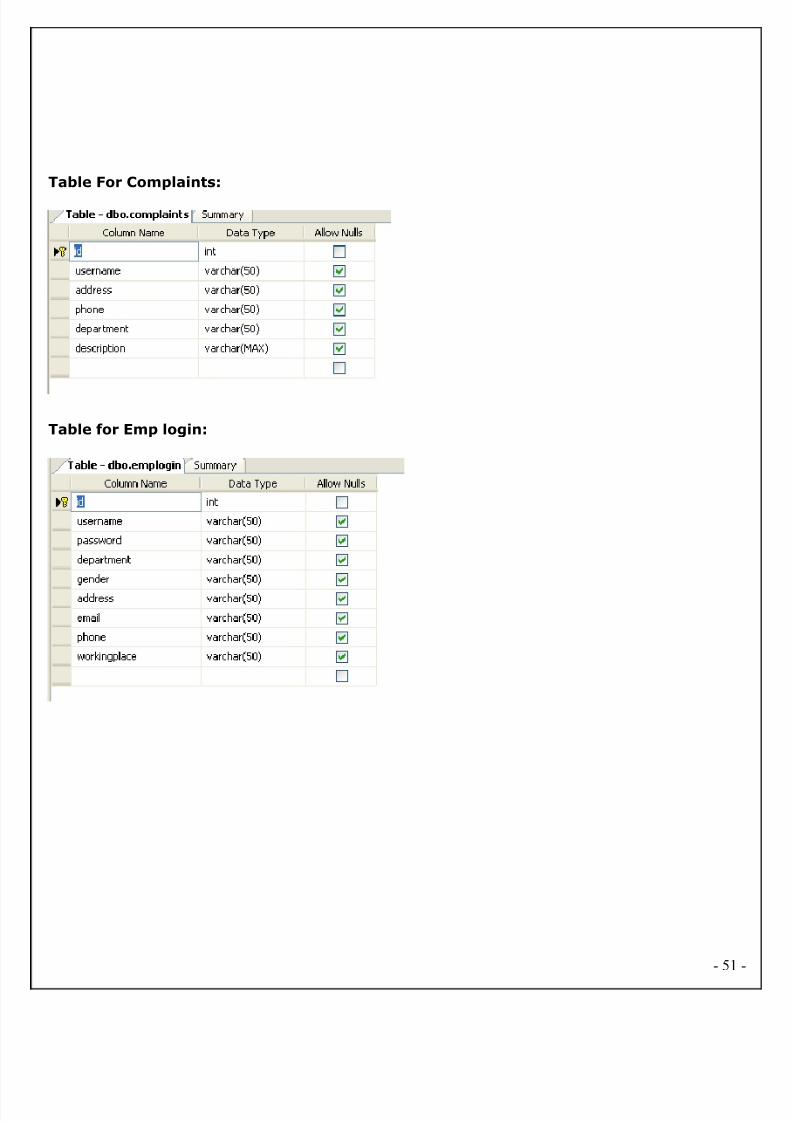
6.3. DATA DICTIONARY
Database Tables (Data Dictionary): After careful analysis the system has identified to be
presented with the following database tables:
Table for Admin login:
Table for Assign Complaint:
- 50
8/2/2019 EndUser Accusation Documentation
http://slidepdf.com/reader/full/enduser-accusation-documentation 51/126
Table For Complaints:
Table for Emp login:
- 51

8/2/2019 EndUser Accusation Documentation
http://slidepdf.com/reader/full/enduser-accusation-documentation 52/126
Table For Resend:
Table For User Registration:
- 52

8/2/2019 EndUser Accusation Documentation
http://slidepdf.com/reader/full/enduser-accusation-documentation 53/126
Data Base Diagram:
- 53
Send complaints to complaint boxAdmin
send
delivery
report to
Assigning Complaints to the Employees
Employee sends complaints
status reports to admin
8/2/2019 EndUser Accusation Documentation
http://slidepdf.com/reader/full/enduser-accusation-documentation 54/126
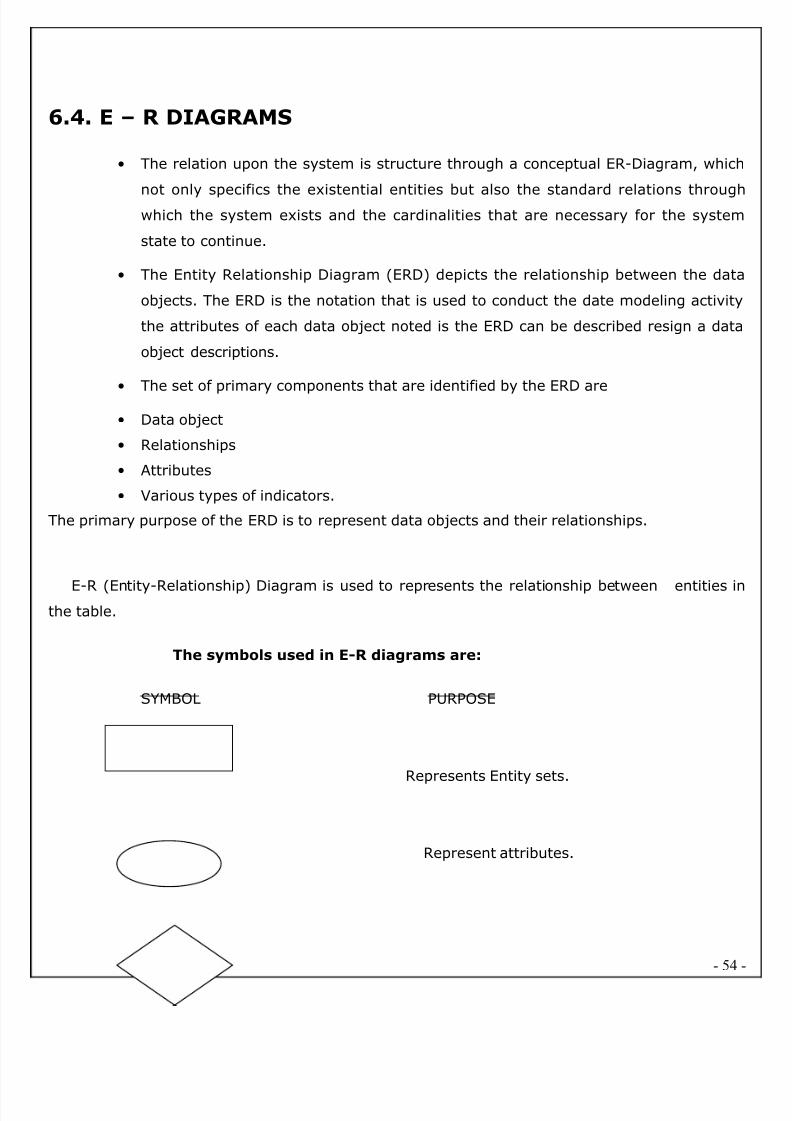
6.4. E – R DIAGRAMS
• The relation upon the system is structure through a conceptual ER-Diagram, which
not only specifics the existential entities but also the standard relations throughwhich the system exists and the cardinalities that are necessary for the system
state to continue.
• The Entity Relationship Diagram (ERD) depicts the relationship between the data
objects. The ERD is the notation that is used to conduct the date modeling activity
the attributes of each data object noted is the ERD can be described resign a data
object descriptions.
•
The set of primary components that are identified by the ERD are
• Data object
• Relationships
• Attributes
• Various types of indicators.
The primary purpose of the ERD is to represent data objects and their relationships.
E-R (Entity-Relationship) Diagram is used to represents the relationship between entities inthe table.
The symbols used in E-R diagrams are:
SYMBOL PURPOSE
Represents Entity sets.
Represent attributes.
- 54
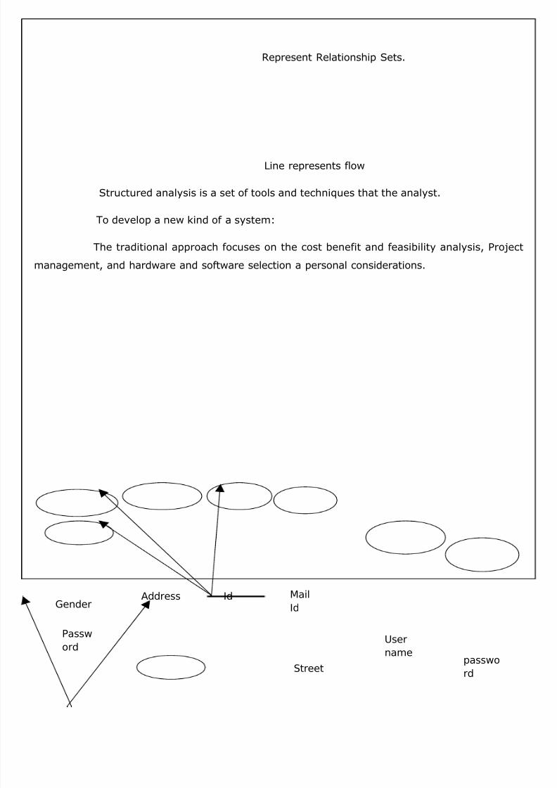
8/2/2019 EndUser Accusation Documentation
http://slidepdf.com/reader/full/enduser-accusation-documentation 55/126
Represent Relationship Sets.
Line represents flow
Structured analysis is a set of tools and techniques that the analyst.
To develop a new kind of a system:
The traditional approach focuses on the cost benefit and feasibility analysis, Project
management, and hardware and software selection a personal considerations.
- 55
passwo
rd
Passw
ord
GenderAddress Id Mail
Id
User
name
Street
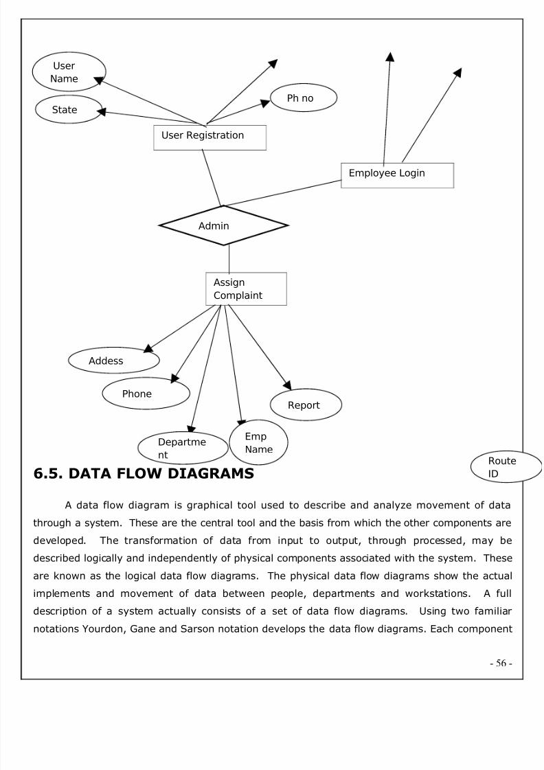
8/2/2019 EndUser Accusation Documentation
http://slidepdf.com/reader/full/enduser-accusation-documentation 56/126
6.5. DATA FLOW DIAGRAMS
A data flow diagram is graphical tool used to describe and analyze movement of data
through a system. These are the central tool and the basis from which the other components are
developed. The transformation of data from input to output, through processed, may be
described logically and independently of physical components associated with the system. These
are known as the logical data flow diagrams. The physical data flow diagrams show the actua
implements and movement of data between people, departments and workstations. A ful
description of a system actually consists of a set of data flow diagrams. Using two familia
notations Yourdon, Gane and Sarson notation develops the data flow diagrams. Each componen
- 56
Admin
User Registration
Employee Login
Assign
Complaint
Addess
Phone
Rout
ID
Report
User
Name
Departme
nt
Emp
Name
StatePh no

8/2/2019 EndUser Accusation Documentation
http://slidepdf.com/reader/full/enduser-accusation-documentation 57/126
in a DFD is labeled with a descriptive name. Process is further identified with a number that wil
be used for identification purpose. The development of DFD’S is done in several levels. Each
process in lower level diagrams can be broken down into a more detailed DFD in the next level.
The lop-level diagram is often called context diagram. It consist a single process bit, which plays
vital role in studying the current system. The process in the context level diagram is exploded
into other process at the first level DFD.
The idea behind the explosion of a process into more process is that understanding at one
level of detail is exploded into greater detail at the next level. This is done until further explosion
is necessary and an adequate amount of detail is described for analyst to understand the
process.
Larry Constantine first developed the DFD as a way of expressing system requirements in
a graphical from, this lead to the modular design.
A DFD is also known as a “bubble Chart” has the purpose of clarifying system
requirements and identifying major transformations that will become programs in system design
So it is the starting point of the design to the lowest level of detail. A DFD consists of a series o
bubbles joined by data flows in the system.
DFD SYMBOLS:
In the DFD, there are four symbols
1. A square defines a source(originator) or destination of system data
2. An arrow identifies data flow. It is the pipeline through which the information flows
3. A circle or a bubble represents a process that transforms incoming data flow into outgoing
data flows.
4. An open rectangle is a data store, data at rest or a temporary repository of data
Process that transforms data flow
Source or Destination of data
Data flow
- 57

8/2/2019 EndUser Accusation Documentation
http://slidepdf.com/reader/full/enduser-accusation-documentation 58/126
Data Store
CONSTRUCTING A DFD:
Several rules of thumb are used in drawing DFD’S:
1. Process should be named and numbered for an easy reference. Each name should be
representative of the process.
2. The direction of flow is from top to bottom and from left to right. Data traditionally flow from
source to the destination although they may flow back to the source. One way to indicate this
is to draw long flow line back to a source. An alternative way is to repeat the source symbo
as a destination. Since it is used more than once in the DFD it is marked with a short
diagonal.3. When a process is exploded into lower level details, they are numbered.
4. The names of data stores and destinations are written in capital letters. Process and dataflow
names have the first letter of each work capitalized
A DFD typically shows the minimum contents of data store. Each data store should
contain all the data elements that flow in and out.
Questionnaires should contain all the data elements that flow in and out. Missinginterfaces redundancies and like is then accounted for often through interviews.
SAILENT FEATURES OF DFD’S
1. The DFD shows flow of data, not of control loops and decision are controlled considerations
do not appear on a DFD.
2. The DFD does not indicate the time factor involved in any process whether the dataflow
take place daily, weekly, monthly or yearly.
3. The sequence of events is not brought out on the DFD.
TYPES OF DATA FLOW DIAGRAMS
1. Current Physical
2. Current Logical
3. New Logical
- 58
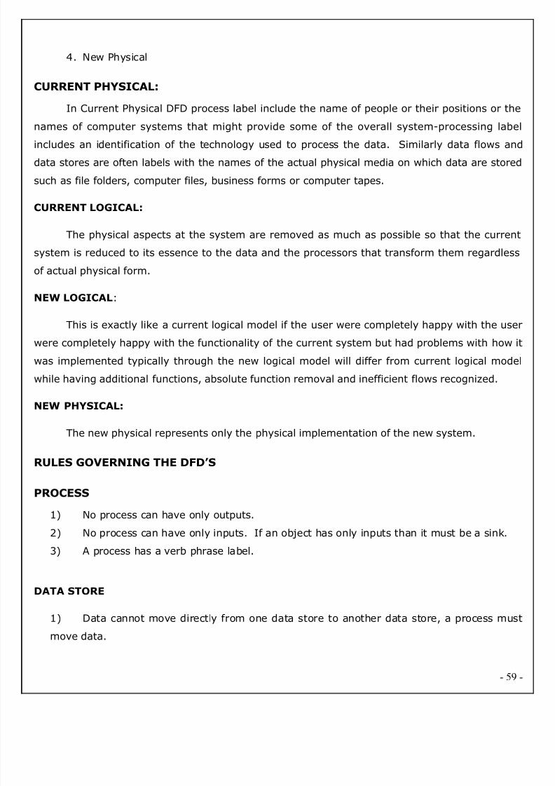
8/2/2019 EndUser Accusation Documentation
http://slidepdf.com/reader/full/enduser-accusation-documentation 59/126
4. New Physical
CURRENT PHYSICAL:
In Current Physical DFD process label include the name of people or their positions or the
names of computer systems that might provide some of the overall system-processing labe
includes an identification of the technology used to process the data. Similarly data flows and
data stores are often labels with the names of the actual physical media on which data are stored
such as file folders, computer files, business forms or computer tapes.
CURRENT LOGICAL:
The physical aspects at the system are removed as much as possible so that the current
system is reduced to its essence to the data and the processors that transform them regardless
of actual physical form.
NEW LOGICAL:
This is exactly like a current logical model if the user were completely happy with the use
were completely happy with the functionality of the current system but had problems with how i
was implemented typically through the new logical model will differ from current logical mode
while having additional functions, absolute function removal and inefficient flows recognized.
NEW PHYSICAL:
The new physical represents only the physical implementation of the new system.
RULES GOVERNING THE DFD’S
PROCESS
1) No process can have only outputs.
2) No process can have only inputs. If an object has only inputs than it must be a sink.
3) A process has a verb phrase label.
DATA STORE
1) Data cannot move directly from one data store to another data store, a process mus
move data.
- 59
8/2/2019 EndUser Accusation Documentation
http://slidepdf.com/reader/full/enduser-accusation-documentation 60/126
2) Data cannot move directly from an outside source to a data store, a process, which
receives, must move data from the source and place the data into data store
3) A data store has a noun phrase label.
SOURCE OR SINK
The origin and /or destination of data
1) Data cannot move direly from a source to sink it must be moved by a process
2) A source and /or sink has a noun phrase land
DATA FLOW
1) A Data Flow has only one direction of flow between symbols. It may flow in both
directions between a process and a data store to show a read before an update. The later is
usually indicated however by two separate arrows since these happen at different type.
2) A join in DFD means that exactly the same data comes from any of two or more
different processes data store or sink to a common location.
3) A data flow cannot go directly back to the same process it leads. There must be a
least one other process that handles the data flow produce some other data flow returns the
original data into the beginning process.
4) A Data flow to a data store means update (delete or change).
5) A data Flow from a data store means retrieve or use.
A data flow has a noun phrase label more than one data flow noun phrase can appear on a single
arrow as long as all of the flows on the same arrow move together as one package
Zero level or Context lEVEL
First level or subsystem level Dataflow:
DFD For Administrator
- 60
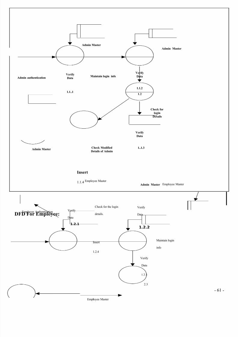
8/2/2019 EndUser Accusation Documentation
http://slidepdf.com/reader/full/enduser-accusation-documentation 61/126
DFD For Employee:
- 61
Admin authenticationVerify
Data
1.1..1
Verify
Data
1.1.2
1.2
Verify
Data
1..1.3
Admin Master
Admin Master
Admin Master
Maintain login info
Insert
1.1.4
Admin MasterCheck Modified
Details of Admin
Check for
login
Details
Employee Master
Employee Authentication Verify
Data
1.2.1
Verify
Data
1.2.2
Verify
Data
1.2.3
2.3
Employee Master
Check for the login
details.
Insert
1.2.4
tEmployee Master
Maintain login
info
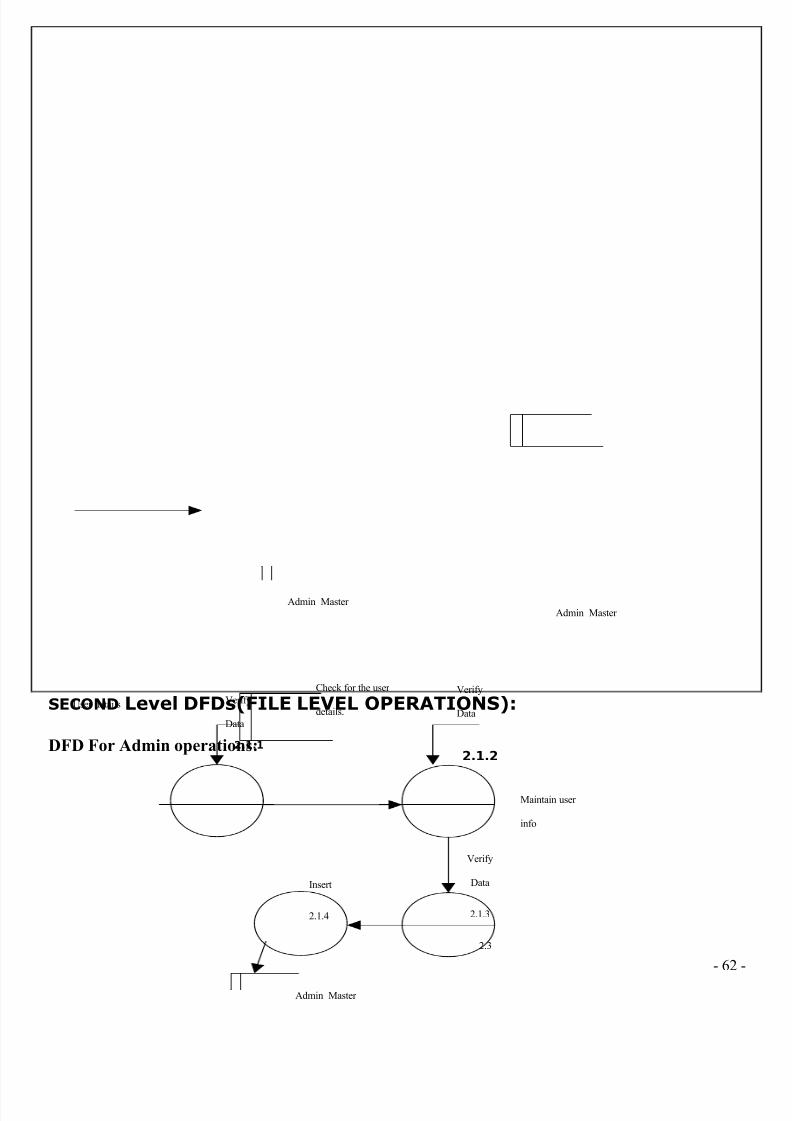
8/2/2019 EndUser Accusation Documentation
http://slidepdf.com/reader/full/enduser-accusation-documentation 62/126
SECOND Level DFDs(FILE LEVEL OPERATIONS):
DFD For Admin operations:
- 62
Admin Master
User details Verify
Data
2.1.1
Verify
Data
2.1.2
Verify
Data
2.1.3
2.3
Admin Master
Check for the user
details.
Insert
2.1.4
Admin Master
Maintain user
info

8/2/2019 EndUser Accusation Documentation
http://slidepdf.com/reader/full/enduser-accusation-documentation 63/126
DFD For user operations:
- 63
User Master
Verify
Data
2.2.1
Verify
Data
2.2.2
Verify
Data
2.2.3
2.3
User Master
Check for the
details.
Insert
2.2.4
User Master
Maintain
complaint info

8/2/2019 EndUser Accusation Documentation
http://slidepdf.com/reader/full/enduser-accusation-documentation 64/126
6.6. ACTIVITY DIAGRAMS
A State diagram/Activity diagram is a specification of the
sequences of states that an object or an interaction goes through in response to events during its
life, together with its responsive action. Every state diagram is having one entry and exit state
And the state can have any number of sub-states. The above state diagram represents, how
admin will interact with other objects, and how he will perform actions and change his state.
- 64
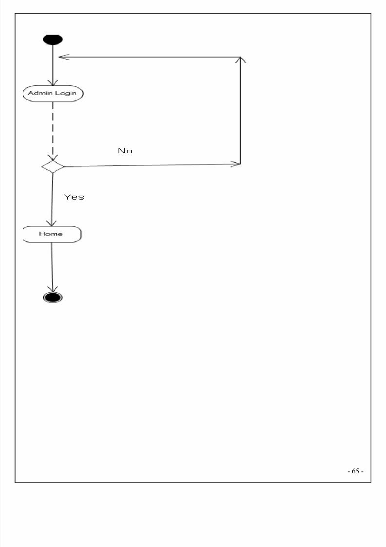
8/2/2019 EndUser Accusation Documentation
http://slidepdf.com/reader/full/enduser-accusation-documentation 65/126
- 65

8/2/2019 EndUser Accusation Documentation
http://slidepdf.com/reader/full/enduser-accusation-documentation 66/126
6.7. USE CASE DIAGRAMS
USECASE is a description of a set of sequence of actions that a system performs that yields
an observable result of value to a particular things in a model. User is an actor and these are
use cases are login, view work details, assign work, approval link, view voter request details,
view ward member and helper details.
Identification of actors:
- 66
8/2/2019 EndUser Accusation Documentation
http://slidepdf.com/reader/full/enduser-accusation-documentation 67/126
Actor: Actor represents the role a user plays with respect to the system. An actor interacts with
but has no control over the use cases.
An actor is someone or something that:
• Interacts with or uses the system.
• Provides input to and receives information from the system.
• Is external to the system and has no control over the use cases.
Actors are discovered by examining:
• Who directly uses the system?
• Who is responsible for maintaining the system?
• External hardware used by the system.
• Other systems that need to interact with the system.
Questions to identify actors:
• Who is using the system? Or, who is affected by the system? Or, which groups need help
from the system to perform a task?
• Who affects the system? Or, which user groups are needed by the system to perform its
functions? These functions can be both main functions and secondary functions such as
administration.
• Which external hardware or systems (if any) use the system to perform tasks?
• What problems does this application solve (that is, for whom)?
• And, finally, how do users use the system (use case)? What are they doing with the
system?
Identification of use cases:
Use case: A use case can be described as a specific way of using the system from a user’s
(actor’s) perspective.
- 67
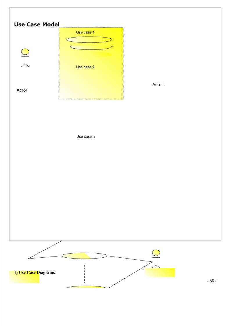
8/2/2019 EndUser Accusation Documentation
http://slidepdf.com/reader/full/enduser-accusation-documentation 68/126
Use Case Model
1) Use Case Diagrams
- 68
Use case 1
Use case 2
Use case n
Actor
Actor
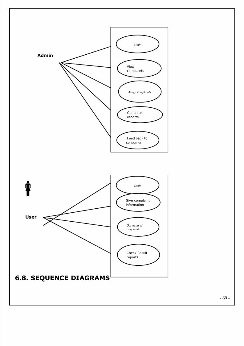
8/2/2019 EndUser Accusation Documentation
http://slidepdf.com/reader/full/enduser-accusation-documentation 69/126
6.8. SEQUENCE DIAGRAMS
- 69
Login
View
complaints
Assign complaints
Generate
reports
Feed back to
consumer
Admin
Login
Give complaint
information
Get status of
complaint
Check Result
reports
User
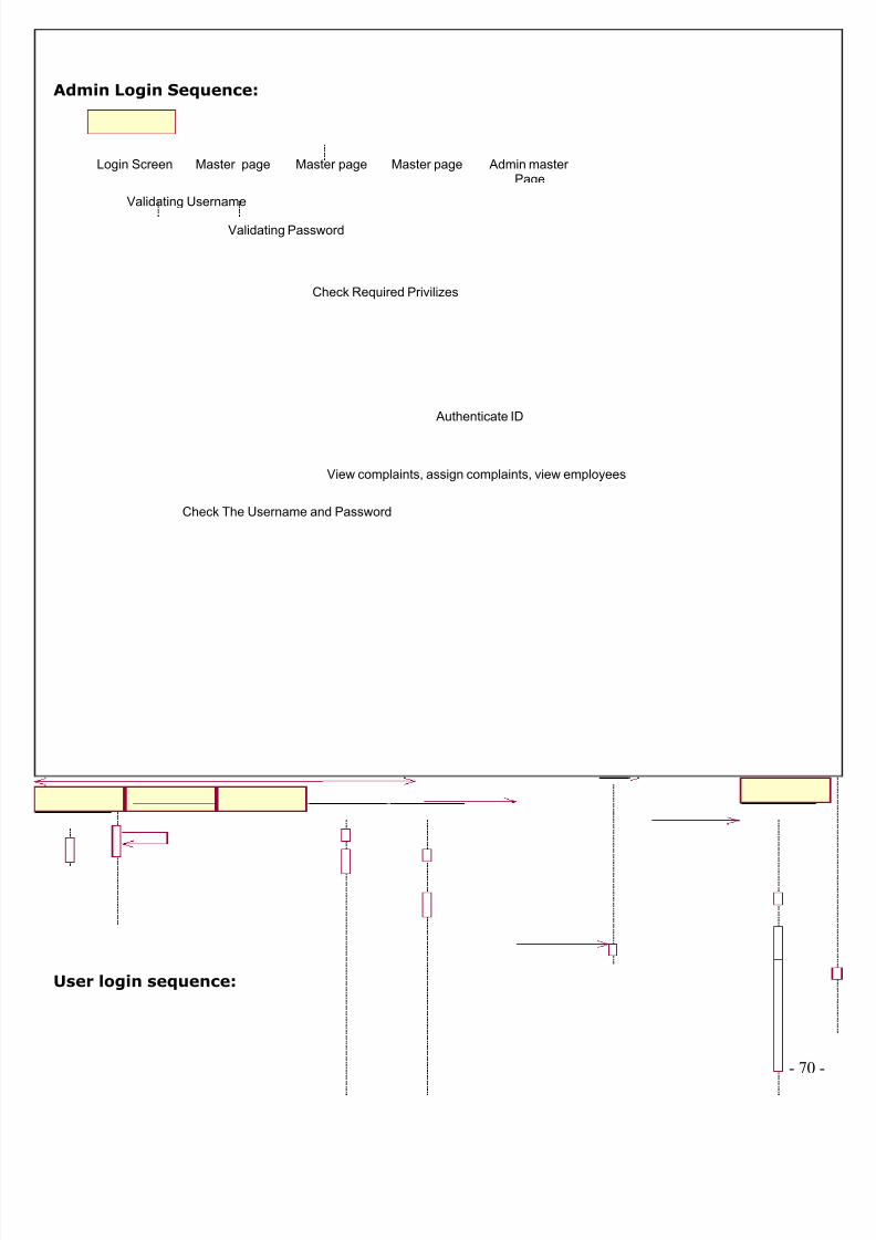
8/2/2019 EndUser Accusation Documentation
http://slidepdf.com/reader/full/enduser-accusation-documentation 70/126
Admin Login Sequence:
User login sequence:
- 70
Login Screen Master page Master page Master page Admin master Page
Validating Username
Authenticate ID
Check The Username and Password
Validating Password
Check Required Privilizes
View complaints, assign complaints, view employees
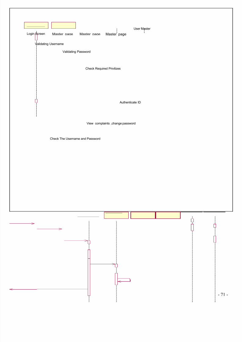
8/2/2019 EndUser Accusation Documentation
http://slidepdf.com/reader/full/enduser-accusation-documentation 71/126
- 71
Login Screen Master page Master page Master page
User Master
Validating Username
Authenticate ID
Check The Username and Password
Validating Password
Check Required Privilizes
View complaints ,change password

8/2/2019 EndUser Accusation Documentation
http://slidepdf.com/reader/full/enduser-accusation-documentation 72/126
6.9. CLASS DIAGRAMS
Identification of analysis classes:
A class is a set of objects that share a common structure and common behavior (the same
attributes, operations, relationships and semantics). A class is an abstraction of real-world
items.
There are 4 approaches for identifying classes:
1. Noun phrase approach:
2. Common class pattern approach.
3. Use case Driven Sequence or Collaboration approach.
4. Classes , Responsibilities and collaborators Approach
1. Noun Phrase Approach:
The guidelines for identifying the classes:
a. Look for nouns and noun phrases in the use cases.
b. Some classes are implicit or taken from general knowledge.
c. All classes must make sense in the application domain; Avoid computer implementation
classes – defer them to the design stage.
d. Carefully choose and define the class names.
After identifying the classes we have to eliminate the following types of classes:
a. Redundant classes.
b. Adjective classes.
- 72
8/2/2019 EndUser Accusation Documentation
http://slidepdf.com/reader/full/enduser-accusation-documentation 73/126
2. Common class pattern approach:
The following are the patterns for finding the candidate classes:
a. Concept class.
b. Events class.
c. Organization class
d. Peoples class
e. Places class
f. Tangible things and devices class.
3. Use case driven approach:
We have to draw the sequence diagram or collaboration diagram. If there is need for some
classes to represent some functionality then add new classes which perform those functionalities
4. CRC approach:
The process consists of the following steps:
a. Identify classes’ responsibilities ( and identify the classes )
b. Assign the responsibilities
c. Identify the collaborators.
Identification of responsibilities of each class:
The questions that should be answered to identify the attributes and methods of a class
respectively are:
1. What information about an object should we keep track of?
2. What services must a class provide?
Identification of relationships among the classes:
- 73
8/2/2019 EndUser Accusation Documentation
http://slidepdf.com/reader/full/enduser-accusation-documentation 74/126
Three types of relationships among the objects are:
Association: How objects are associated?
Super-sub structure: How are objects organized into super classes and sub classes?
Aggregation: What is the composition of the complex classes?
Guidelines for identifying the tentative associations:
• A dependency between two or more classes may be an association. Association often
corresponds to a verb or prepositional phrase.
• A reference from one class to another is an association. Some associations are implicit or
taken from general knowledge.
Super-sub class relationships
Super-sub class hierarchy is a relationship between classes where one class is the paren
class of another class (derived class).This is based on inheritance. This hierarchy is represented
with Generalization.
Guidelines for identifying the super-sub relationship, a generalization are
1. Top-down: Look for noun phrases composed of various adjectives in a class name. Avoid
excessive refinement. Specialize only when the sub classes have significant behavior.
2. Bottom-up: Look for classes with similar attributes or methods. Group them by moving the
common attributes and methods to an abstract class. You may have to alter the definitions a bit.
- 74
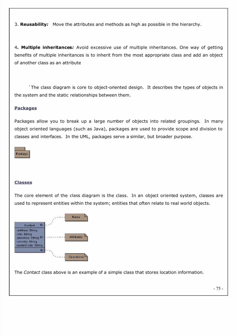
8/2/2019 EndUser Accusation Documentation
http://slidepdf.com/reader/full/enduser-accusation-documentation 75/126
3. Reusability: Move the attributes and methods as high as possible in the hierarchy.
4. Multiple inheritances: Avoid excessive use of multiple inheritances. One way of getting
benefits of multiple inheritances is to inherit from the most appropriate class and add an object
of another class as an attribute
`The class diagram is core to object-oriented design. It describes the types of objects in
the system and the static relationships between them.
Packages
Packages allow you to break up a large number of objects into related groupings. In many
object oriented languages (such as Java), packages are used to provide scope and division to
classes and interfaces. In the UML, packages serve a similar, but broader purpose.
Classes
The core element of the class diagram is the class. In an object oriented system, classes are
used to represent entities within the system; entities that often relate to real world objects.
The Contact class above is an example of a simple class that stores location information.
- 75
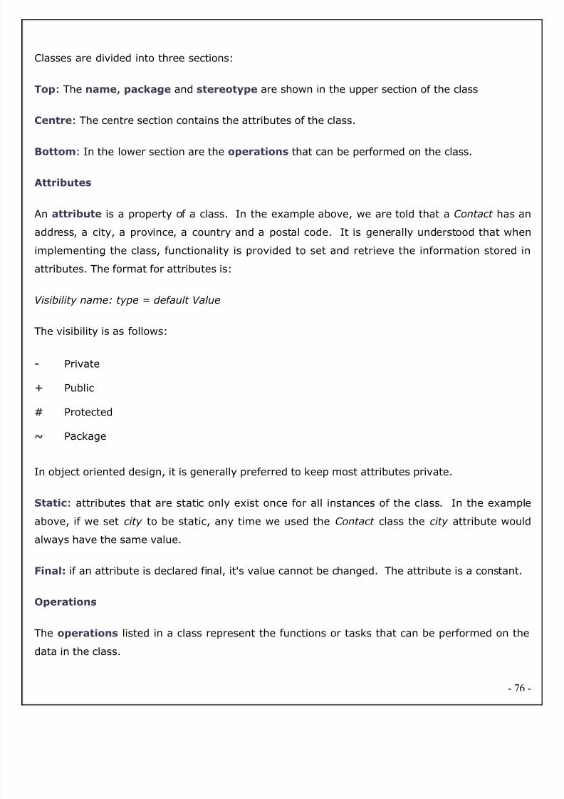
8/2/2019 EndUser Accusation Documentation
http://slidepdf.com/reader/full/enduser-accusation-documentation 76/126
Classes are divided into three sections:
Top: The name, package and stereotype are shown in the upper section of the class
Centre: The centre section contains the attributes of the class.
Bottom: In the lower section are the operations that can be performed on the class.
Attributes
An attribute is a property of a class. In the example above, we are told that a Contact has an
address, a city, a province, a country and a postal code. It is generally understood that when
implementing the class, functionality is provided to set and retrieve the information stored in
attributes. The format for attributes is:
Visibility name: type = default Value
The visibility is as follows:
- Private
+ Public
# Protected
~ Package
In object oriented design, it is generally preferred to keep most attributes private.
Static: attributes that are static only exist once for all instances of the class. In the example
above, if we set city to be static, any time we used the Contact class the city attribute would
always have the same value.
Final: if an attribute is declared final, it's value cannot be changed. The attribute is a constant.
Operations
The operations listed in a class represent the functions or tasks that can be performed on the
data in the class.
- 76
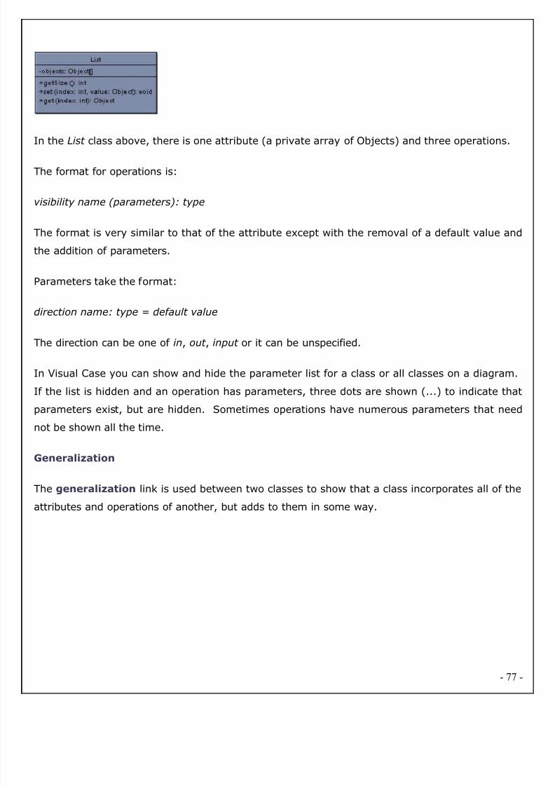
8/2/2019 EndUser Accusation Documentation
http://slidepdf.com/reader/full/enduser-accusation-documentation 77/126
In the List class above, there is one attribute (a private array of Objects) and three operations.
The format for operations is:
visibility name (parameters): type
The format is very similar to that of the attribute except with the removal of a default value and
the addition of parameters.
Parameters take the format:
direction name: type = default value
The direction can be one of in, out , input or it can be unspecified.
In Visual Case you can show and hide the parameter list for a class or all classes on a diagram.
If the list is hidden and an operation has parameters, three dots are shown (...) to indicate tha
parameters exist, but are hidden. Sometimes operations have numerous parameters that neednot be shown all the time.
Generalization
The generalization link is used between two classes to show that a class incorporates all of the
attributes and operations of another, but adds to them in some way.
- 77
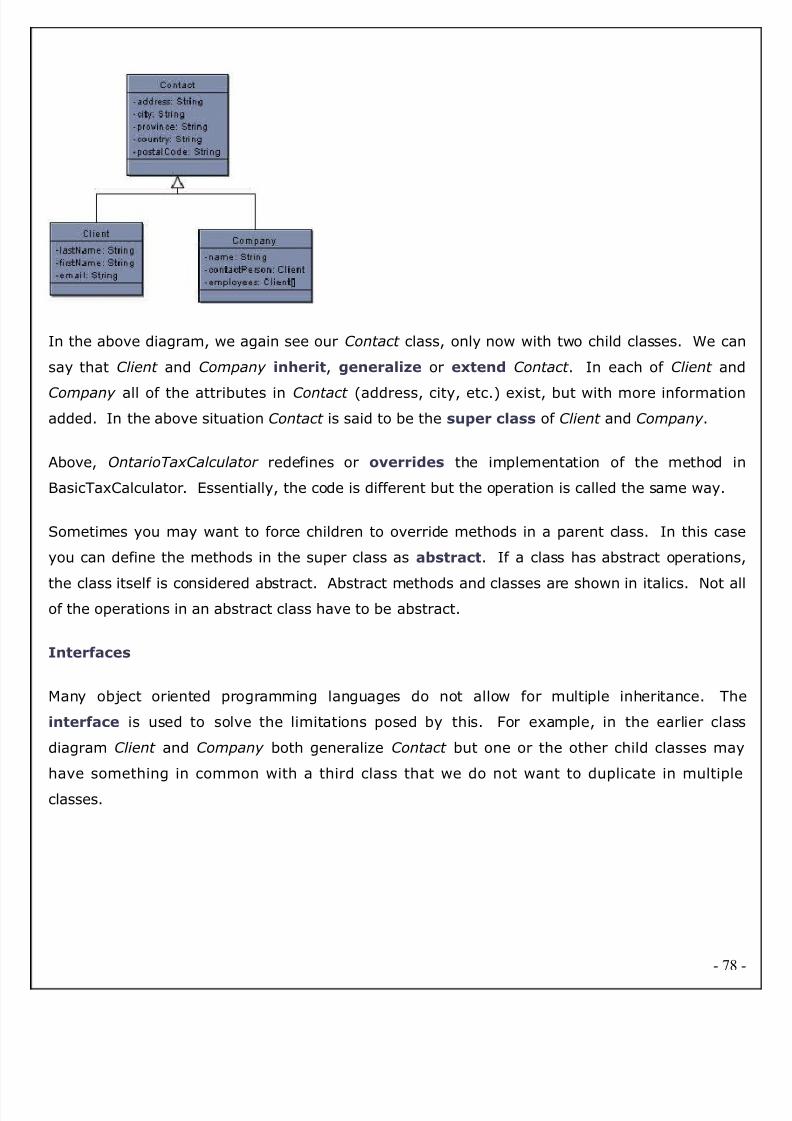
8/2/2019 EndUser Accusation Documentation
http://slidepdf.com/reader/full/enduser-accusation-documentation 78/126
In the above diagram, we again see our Contact class, only now with two child classes. We can
say that Client and Company inherit, generalize or extend Contact . In each of Client and
Company all of the attributes in Contact (address, city, etc.) exist, but with more information
added. In the above situation Contact is said to be the super class of Client and Company .
Above, OntarioTaxCalculator redefines or overrides the implementation of the method in
BasicTaxCalculator. Essentially, the code is different but the operation is called the same way.
Sometimes you may want to force children to override methods in a parent class. In this case
you can define the methods in the super class as abstract. If a class has abstract operations
the class itself is considered abstract. Abstract methods and classes are shown in italics. Not alof the operations in an abstract class have to be abstract.
Interfaces
Many object oriented programming languages do not allow for multiple inheritance. The
interface is used to solve the limitations posed by this. For example, in the earlier class
diagram Client and Company both generalize Contact but one or the other child classes may
have something in common with a third class that we do not want to duplicate in multiple
classes.
- 78

8/2/2019 EndUser Accusation Documentation
http://slidepdf.com/reader/full/enduser-accusation-documentation 79/126
The interface Sort able, is used in the above example to show that both Company and Produc
implement the sort operation. We can say that Company and Product implement Sort able o
that they are Sort able. Because Product already generalizes Contact , we could not also allow i
to generalize Sort able. Instead, we made Sort able an interface and added a realization link to
show the implementation.
Interfaces are very similar to abstract classes with the exception that they do not have any
attributes. As well, unlike a class, all of the operations in an interface have no implementation.
The child Classes Company and Product are forced to implement the sort operation in its
entirety.
Associations
Classes can also contain references to each other. The Company class has two attributes tha
reference the Client class.
Although this is perfectly correct, it is sometimes more expressive to show the attributes as
associations.
- 79
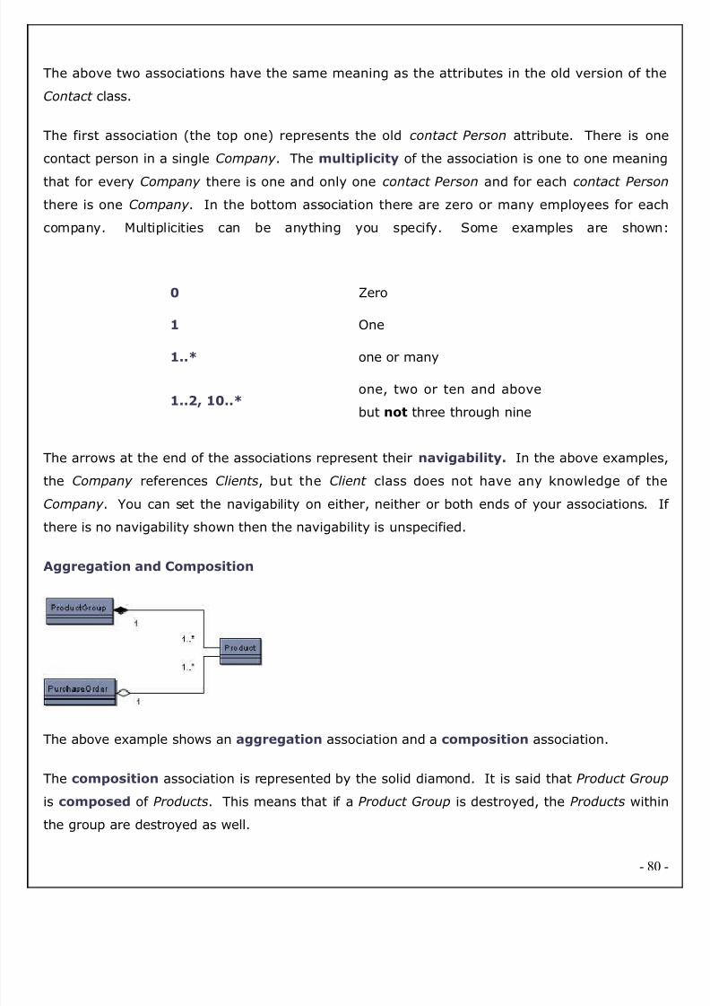
8/2/2019 EndUser Accusation Documentation
http://slidepdf.com/reader/full/enduser-accusation-documentation 80/126
The above two associations have the same meaning as the attributes in the old version of the
Contact class.
The first association (the top one) represents the old contact Person attribute. There is one
contact person in a single Company . The multiplicity of the association is one to one meaning
that for every Company there is one and only one contact Person and for each contact Person
there is one Company . In the bottom association there are zero or many employees for each
company. Multiplicities can be anything you specify. Some examples are shown
0 Zero
1 One
1..* one or many
1..2, 10..*one, two or ten and above
but not three through nine
The arrows at the end of the associations represent their navigability. In the above examples
the Company references Clients, but the Client class does not have any knowledge of the
Company . You can set the navigability on either, neither or both ends of your associations. I
there is no navigability shown then the navigability is unspecified.
Aggregation and Composition
The above example shows an aggregation association and a composition association.
The composition association is represented by the solid diamond. It is said that Product Group
is composed of Products. This means that if a Product Group is destroyed, the Products within
the group are destroyed as well.
- 80

8/2/2019 EndUser Accusation Documentation
http://slidepdf.com/reader/full/enduser-accusation-documentation 81/126
The aggregation association is represented by the hollow diamond. Purchase Order is an
aggregate of Products. If a Purchase Order is destroyed, the Products still exist.
If you have trouble remembering the difference between composition and aggregation, just think
of the alphabet. Composition means destroy and the letters 'c' and 'd' are next to each other.
Dependencies
A dependency exists between two elements if changes to one will affect the other. If fo
example, a class calls an operation in another class, then a dependency exists between the two.
If you change the operation, than the dependent class will have to change as well. When
designing your system, the goal is to minimize dependencies.
To help clarify the dependencies in your design, you may wish to draw a Package Diagram. A
package diagram is essentially a class diagram with only packages and dependencies showing.
Dependencies can exist between any components in the UML however at the highest level,
dependencies will exist between packages. Within a package, the dependencies may be too
numerous to specify. That is not to say that numerous dependencies are okay. Even within a
package you want to limit the dependencies, however between packages in particular you should
be strict about the number of dependencies that exist. In general, the fewer the dependencies
the more scalable and maintainable.
- 81

8/2/2019 EndUser Accusation Documentation
http://slidepdf.com/reader/full/enduser-accusation-documentation 82/126
- 82
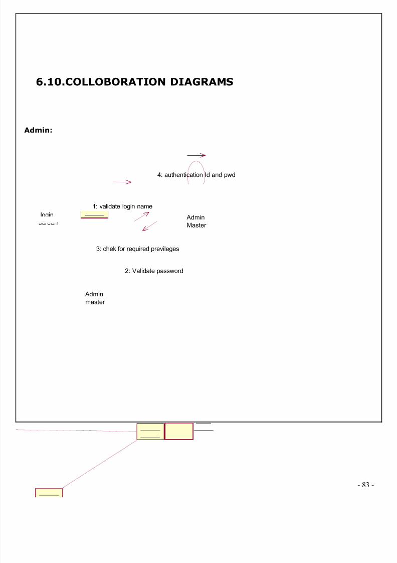
8/2/2019 EndUser Accusation Documentation
http://slidepdf.com/reader/full/enduser-accusation-documentation 83/126
6.10.COLLOBORATION DIAGRAMS
Admin:
login
screen Admin
Master
Adminmaster
1: validate login name
2: Validate password
3: chek for required previleges
4: authentication Id and pwd
- 83
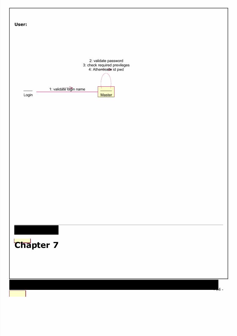
8/2/2019 EndUser Accusation Documentation
http://slidepdf.com/reader/full/enduser-accusation-documentation 84/126
User:
Login Master
1: validate login name
2: validate password3: check required previleges
4: Athenticate id pwd
Chapter 7
- 84

8/2/2019 EndUser Accusation Documentation
http://slidepdf.com/reader/full/enduser-accusation-documentation 85/126
OUTPUT SCREENS
Home Page:
- 85
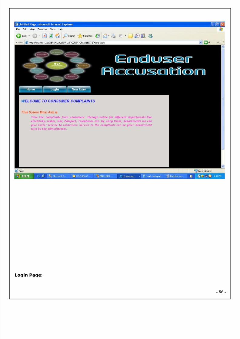
8/2/2019 EndUser Accusation Documentation
http://slidepdf.com/reader/full/enduser-accusation-documentation 86/126
Login Page:
- 86

8/2/2019 EndUser Accusation Documentation
http://slidepdf.com/reader/full/enduser-accusation-documentation 87/126
Admin Login:
- 87

8/2/2019 EndUser Accusation Documentation
http://slidepdf.com/reader/full/enduser-accusation-documentation 88/126
Admin Home:
- 88
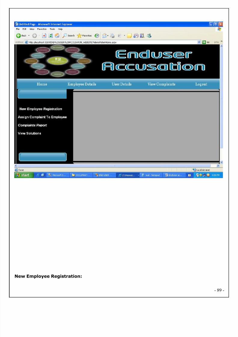
8/2/2019 EndUser Accusation Documentation
http://slidepdf.com/reader/full/enduser-accusation-documentation 89/126
New Employee Registration:
- 89
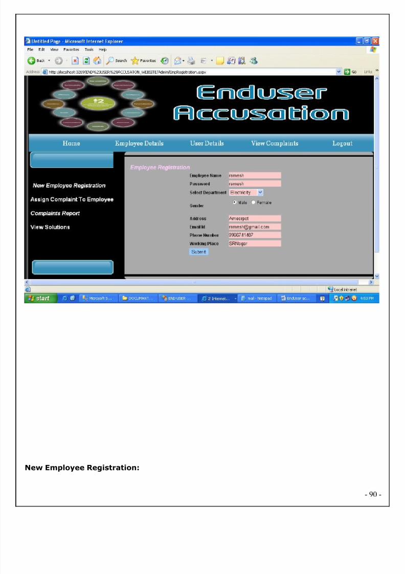
8/2/2019 EndUser Accusation Documentation
http://slidepdf.com/reader/full/enduser-accusation-documentation 90/126
New Employee Registration:
- 90

8/2/2019 EndUser Accusation Documentation
http://slidepdf.com/reader/full/enduser-accusation-documentation 91/126
New user registration:
- 91

8/2/2019 EndUser Accusation Documentation
http://slidepdf.com/reader/full/enduser-accusation-documentation 92/126
User/ Login:
- 92
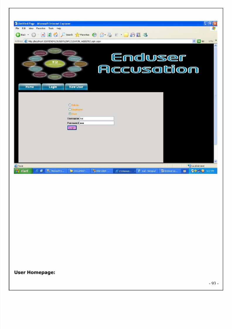
8/2/2019 EndUser Accusation Documentation
http://slidepdf.com/reader/full/enduser-accusation-documentation 93/126
User Homepage:
- 93
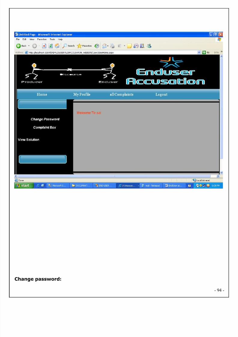
8/2/2019 EndUser Accusation Documentation
http://slidepdf.com/reader/full/enduser-accusation-documentation 94/126
Change password:
- 94

8/2/2019 EndUser Accusation Documentation
http://slidepdf.com/reader/full/enduser-accusation-documentation 95/126
User complaint box:
- 95

8/2/2019 EndUser Accusation Documentation
http://slidepdf.com/reader/full/enduser-accusation-documentation 96/126
Employee login:
- 96
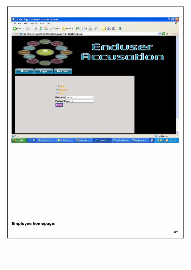
8/2/2019 EndUser Accusation Documentation
http://slidepdf.com/reader/full/enduser-accusation-documentation 97/126
Employee homepage:
- 97
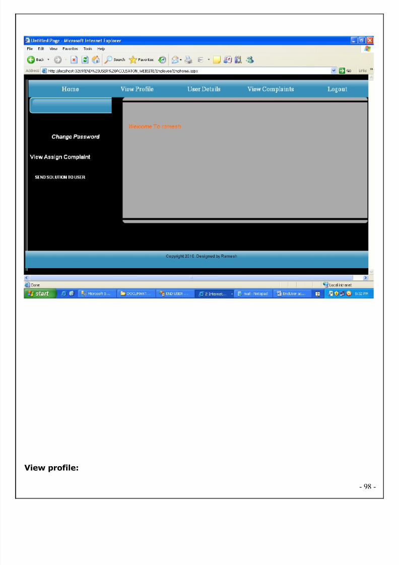
8/2/2019 EndUser Accusation Documentation
http://slidepdf.com/reader/full/enduser-accusation-documentation 98/126
View profile:
- 98

8/2/2019 EndUser Accusation Documentation
http://slidepdf.com/reader/full/enduser-accusation-documentation 99/126
User details:
- 99

8/2/2019 EndUser Accusation Documentation
http://slidepdf.com/reader/full/enduser-accusation-documentation 100/126
View complaints:
- 100

8/2/2019 EndUser Accusation Documentation
http://slidepdf.com/reader/full/enduser-accusation-documentation 101/126
View Assign complaint:
- 101
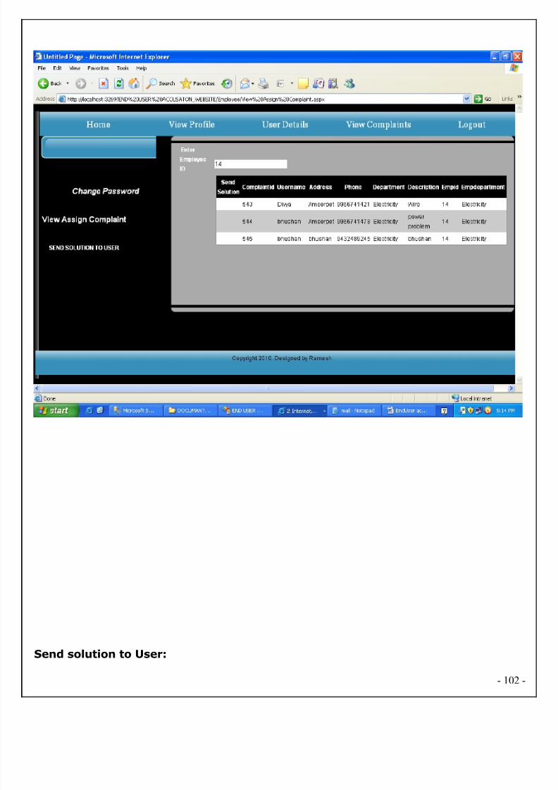
8/2/2019 EndUser Accusation Documentation
http://slidepdf.com/reader/full/enduser-accusation-documentation 102/126
Send solution to User:
- 102

8/2/2019 EndUser Accusation Documentation
http://slidepdf.com/reader/full/enduser-accusation-documentation 103/126
User/view solution:
- 103

8/2/2019 EndUser Accusation Documentation
http://slidepdf.com/reader/full/enduser-accusation-documentation 104/126
User/My profile:
- 104
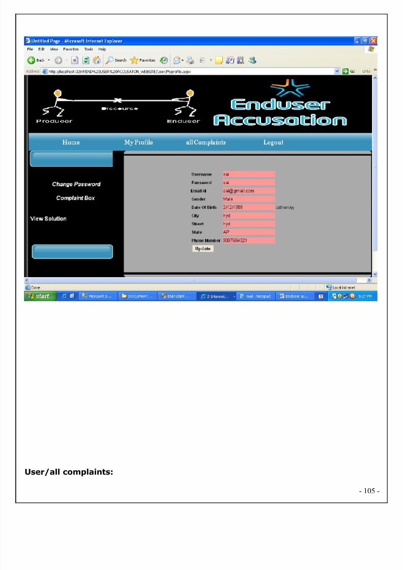
8/2/2019 EndUser Accusation Documentation
http://slidepdf.com/reader/full/enduser-accusation-documentation 105/126
User/all complaints:
- 105
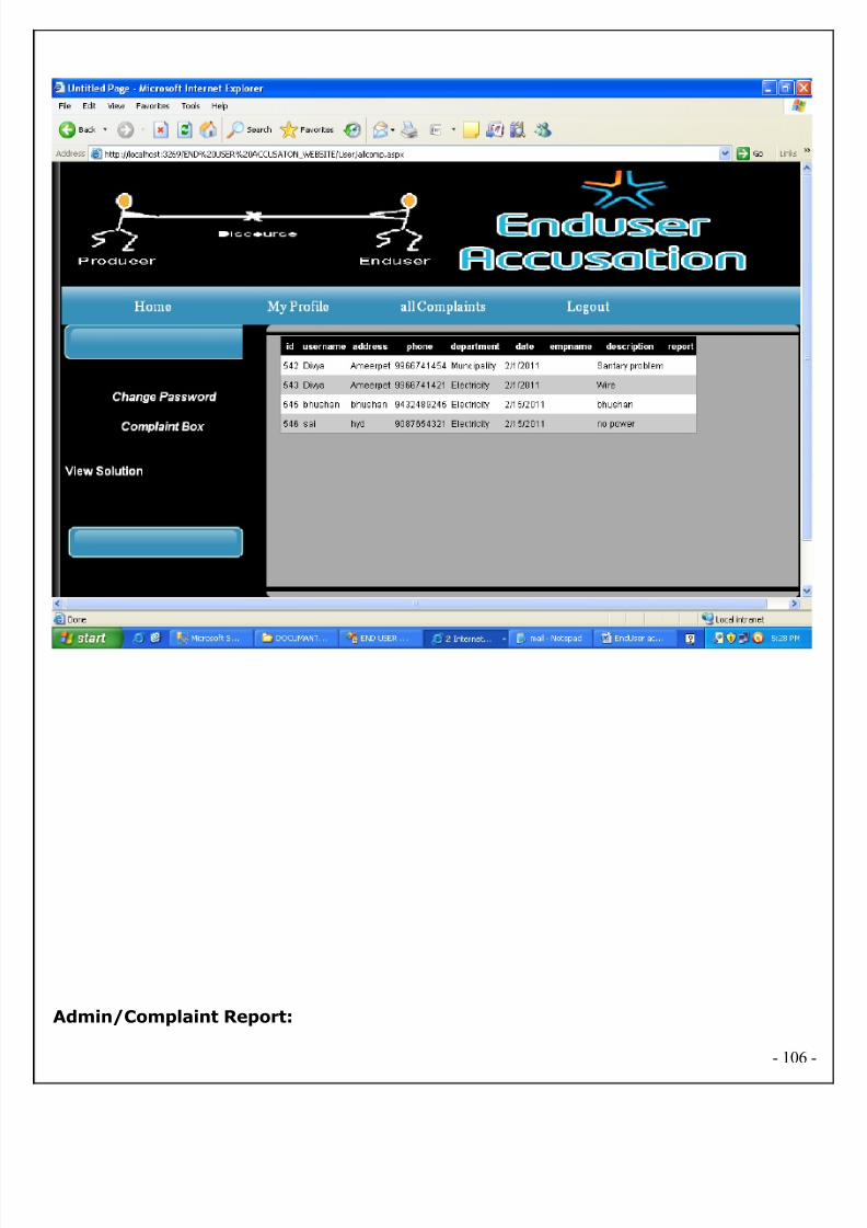
8/2/2019 EndUser Accusation Documentation
http://slidepdf.com/reader/full/enduser-accusation-documentation 106/126
Admin/Complaint Report:
- 106
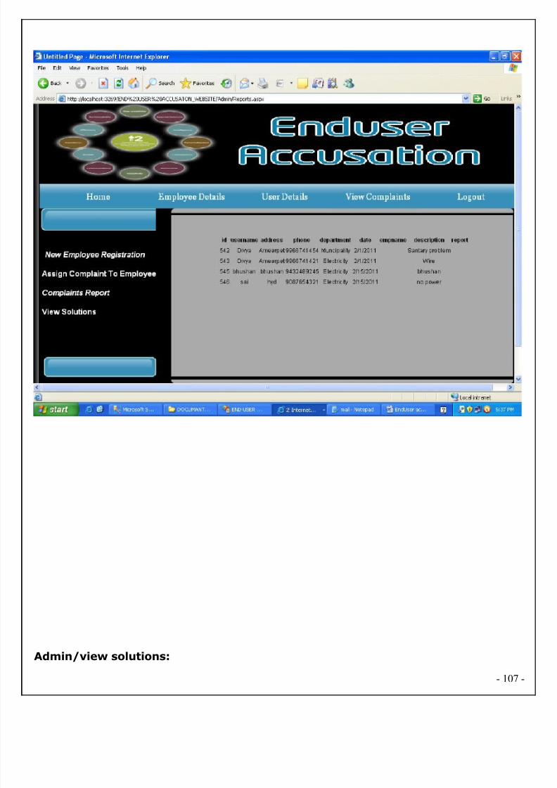
8/2/2019 EndUser Accusation Documentation
http://slidepdf.com/reader/full/enduser-accusation-documentation 107/126
Admin/view solutions:
- 107
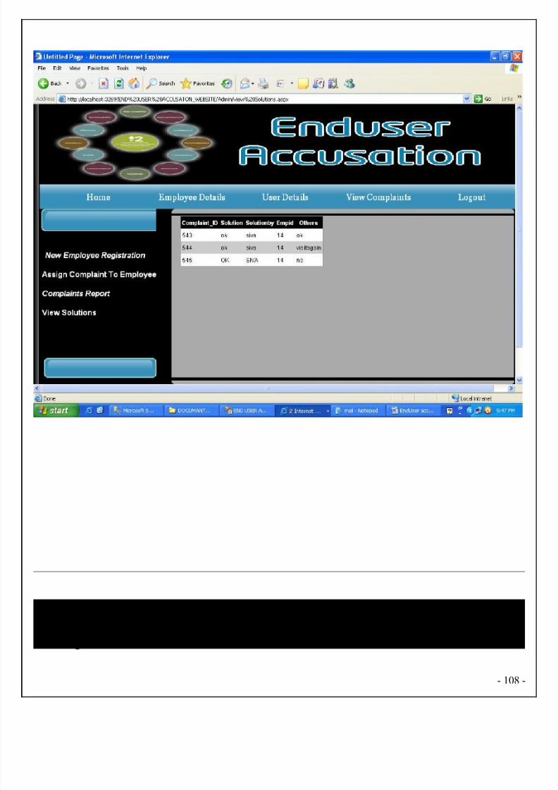
8/2/2019 EndUser Accusation Documentation
http://slidepdf.com/reader/full/enduser-accusation-documentation 108/126
Chapter 8
- 108
8/2/2019 EndUser Accusation Documentation
http://slidepdf.com/reader/full/enduser-accusation-documentation 109/126
SYSTEM TESTING AND IMPLEMENTATION
- 109
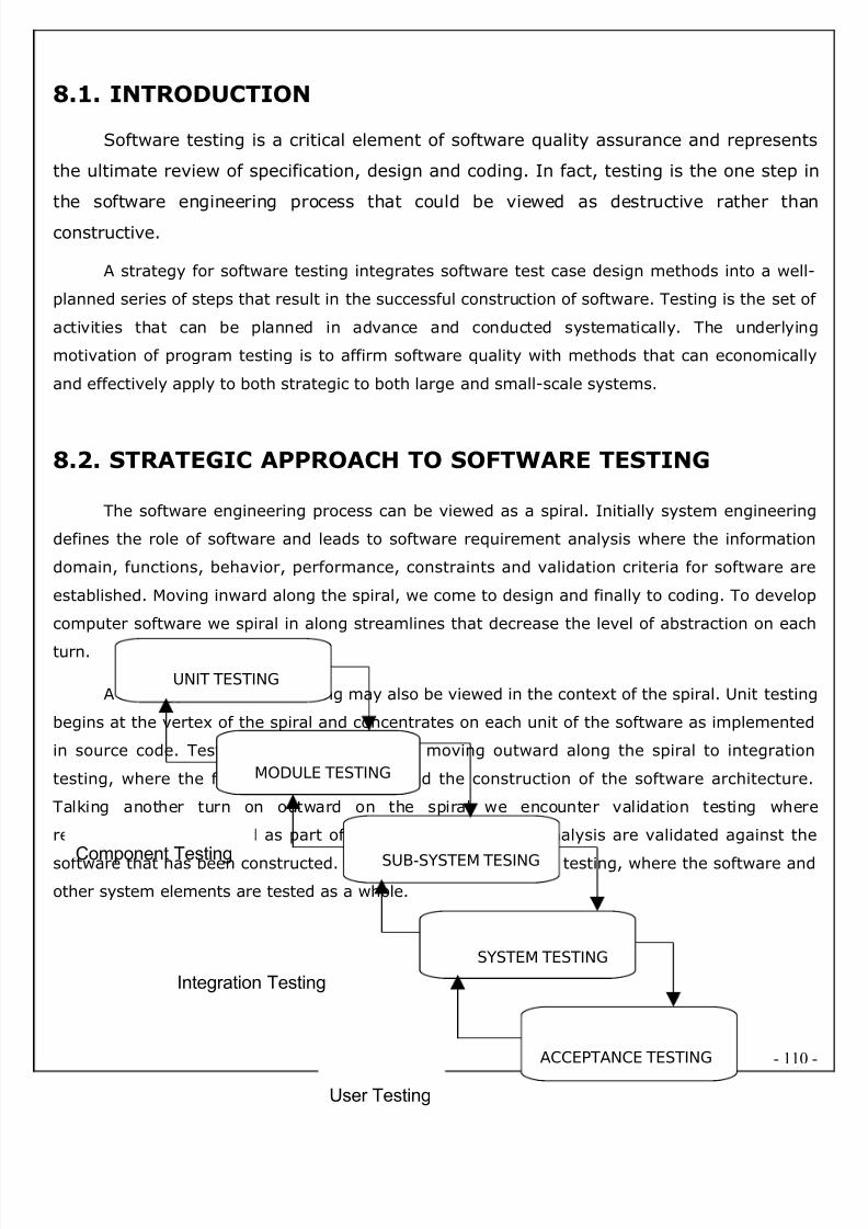
8/2/2019 EndUser Accusation Documentation
http://slidepdf.com/reader/full/enduser-accusation-documentation 110/126
8.1. INTRODUCTION
Software testing is a critical element of software quality assurance and represents
the ultimate review of specification, design and coding. In fact, testing is the one step in
the software engineering process that could be viewed as destructive rather than
constructive.
A strategy for software testing integrates software test case design methods into a well-
planned series of steps that result in the successful construction of software. Testing is the set o
activities that can be planned in advance and conducted systematically. The underlying
motivation of program testing is to affirm software quality with methods that can economically
and effectively apply to both strategic to both large and small-scale systems.
8.2. STRATEGIC APPROACH TO SOFTWARE TESTING
The software engineering process can be viewed as a spiral. Initially system engineering
defines the role of software and leads to software requirement analysis where the information
domain, functions, behavior, performance, constraints and validation criteria for software are
established. Moving inward along the spiral, we come to design and finally to coding. To develop
computer software we spiral in along streamlines that decrease the level of abstraction on each
turn.
A strategy for software testing may also be viewed in the context of the spiral. Unit testing
begins at the vertex of the spiral and concentrates on each unit of the software as implemented
in source code. Testing progress is done by moving outward along the spiral to integration
testing, where the focus is on the design and the construction of the software architecture
Talking another turn on outward on the spiral we encounter validation testing where
requirements established as part of software requirements analysis are validated against the
software that has been constructed. Finally we arrive at system testing, where the software and
other system elements are tested as a whole.
- 110
UNIT TESTING
MODULE TESTING
SUB-SYSTEM TESING
SYSTEM TESTING
ACCEPTANCE TESTING
Component Testing
Integration Testing
User Testing
8/2/2019 EndUser Accusation Documentation
http://slidepdf.com/reader/full/enduser-accusation-documentation 111/126
8.3. Testing Strategies
Testing software is a critical element of software quality assurance and represents the ultimate
review of specification; and coding software testing fundamentals define the overridingobjectives for software testing.
TESTING OBJECTIVES
Testing is a process of executing a program with the intent of finding an error.
A good case is one that has a high probability of finding an error.
A successful test is one that uncovers a yet undiscovered error. If testing is conducted
successfully it will uncover errors in the software. Testing cannot show the absence of
defects, it can only show the software defects are present.
TESTING PRINCIPLES
Before applying methods to design effective test cases, a software engineer must understand the
basic principles that guide e software testing.
- 111
8/2/2019 EndUser Accusation Documentation
http://slidepdf.com/reader/full/enduser-accusation-documentation 112/126
All tests should be traceable to customer requirements.
Test should be planned long before testing begins.
Testing should begin “in small” and progress towards testing “in large”
Exhaustive testing is not possible.
To be most effective. An independent third party should conduct testing.
TESTING TECHNIQUES
The primary objective for test case is to drive a set of sets that has the highest likelihood for
uncovering defects in the software. Testing is the process of executing a program with the inten
of finding as a yet and discovered error. To accomplish this objective tow different categories o
test case technique used.
After test plan and before going to test design test case is important. According to the projec
requirements we have to test some conditions to ensure the quality of software. For the purpose
of testing these conditions we have to write test cases.
TESTING STRATEGIES
Testing is a set of activities that can be planned in advance and connected systematically. A
strategy for software testing must accommodate low level tests that are necessary to verify a
small source code segment has been correctly implemented as well as high level tests that
validate system functions against customer requirements.
8.3.1. TEST CASE PREPARATION
8.3.1.1 BLACK BOX TESTING
The concept of the black box is used to represent a system whose inside workings or no available
for inspection. In a black box, the test item is treated as a “black” since its logic is unknown: althat is known is what goes in and what comes out, or the input and output. Here, in this
“Electronic Management Information System” the internal functionalities have been tested.
8.3.1.2 WHITE BOX TESTING
White box testing assumes that the specific logic is important and must be tested to guarantee
the system’s proper functioning. The main use of the white box testing is in error based testing.
- 112

8/2/2019 EndUser Accusation Documentation
http://slidepdf.com/reader/full/enduser-accusation-documentation 113/126
It is predict on close examination of procedural detail logical providing test cases that exercise
specific sets of conditions and/or loops test path enough the software. Basis path testing is a
white box testing technique. The basis path method enables the test case designer to derive a
logical complexity of a procedural design and use this measure as a guide for defining as basis
set of execution path.
8.3.2 TEST CASE VERIFICATION
8.3.2.1. UNIT TESTING
Unit testing focuses on verifying the effort on the smallest unit of software-module. The
local data structure is examined to ensure that the date stored temporarily maintains its integrity
during all steps in the algorithm’s execution. Boundary conditions are tested to ensure that the
module operates properly at boundaries established to limit or restrict processing.
8.3.2.2. INTEGRATION TESTING
Data can be tested across an interface. One module can have an inadvertent, adverse effect on
the other. Integration testing is a systematic technique for constructing a program structure
while conducting tests to uncover errors associated with interring.
8.3.2.3. PERFORMANCE TESTING
Performance Testing is used to test runtime performance of software within the context of anintegrated system. Performance test are often coupled with stress testing and require both
software instrumentation
8.3.3. VALIDATION TESTING
After performing the validation testing, the next step is output testing of the proposed system
since no system would be termed as useful until it does produce the required output in the
specified format. Output format is considered in two ways, the screen format and the printe
format.
8.3.3.1. SYSTEM TESTING
System Testing is nothing but the testing the entire system. The following test cases are coming
from the system testing.
- 113

8/2/2019 EndUser Accusation Documentation
http://slidepdf.com/reader/full/enduser-accusation-documentation 114/126
8.4. TEST CASES
Test Case Report1
(Use one template for each test case)
GENERAL INFORMATION
Test Stage: Unit Functionality Interface
Performance Acceptance
Test Date: 09/09/2010 System Date, if
applicable:
09/09/2010
Tester: MOHAN Test Case Number: 1
Test Case
Description:Unit testing focuses on verifying the effort on the smallest unit of
software-module. The local data structure is examined to ensure that the datestored temporarily maintains its integrity during all steps in the algorithm’sexecution. Boundary conditions are tested to ensure that the module operatesproperly at boundaries established to limit or restrict processing.
Results: Pass(OK)
Fail
INTRODUCTION
Requirement(s)
to be tested:
Username Text field and Password Text field and the Authority Text Area.
Roles and
Responsibilities:
Gathering the Requirements of the Project Designing and Testing.
Set Up
Procedures:
By Installing Visual Studio.
ENVIRONMENTAL NEEDS
Hardware: PC with Minimum 20GB Hard Disk and 1GB RAM.
Software: Windows XP/2000, MS SQL SERVER 2005/2008, MS VISUAL STUDIO 2008/2010.
TEST
Test Items and
Features:
Username and Password.
- 114
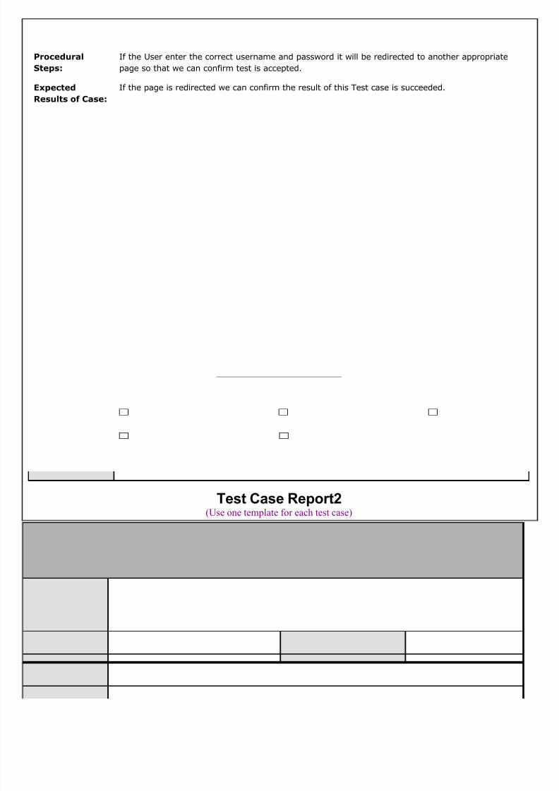
8/2/2019 EndUser Accusation Documentation
http://slidepdf.com/reader/full/enduser-accusation-documentation 115/126
Procedural
Steps:
If the User enter the correct username and password it will be redirected to another appropriate
page so that we can confirm test is accepted.
Expected
Results of Case:
If the page is redirected we can confirm the result of this Test case is succeeded.
Test Case Report2(Use one template for each test case)
GENERAL INFORMATION
Test Stage: Unit Functionality Interface
Performance Acceptance
Test Date: 09/09/2010 System Date, if
applicable:
09/09/2010
Tester: MOHAN Test Case Number: 2
- 115

8/2/2019 EndUser Accusation Documentation
http://slidepdf.com/reader/full/enduser-accusation-documentation 116/126
Test Case
Description:Unit testing focuses on verifying the effort on the smallest unit of
software-module. The local data structure is examined to ensure that the datestored temporarily maintains its integrity during all steps in the algorithm’sexecution. Boundary conditions are tested to ensure that the module operatesproperly at boundaries established to limit or restrict processing.
Results: Pass(OK)
Fail
INTRODUCTION
Requirement(s)
to be tested:
After login user can enter proper details for getting information about complaints, search the
details, contact details.
Roles and
Responsibilities:
Gathering the Requirements of the Project Designing and Testing.
Set Up
Procedures:
By Installing Visual Studio.
ENVIRONMENTAL NEEDS
Hardware: PC with Minimum 20GB Hard Disk and 1GB RAM.
Software: Windows XP/2000, MS SQL SERVER 2005/2008, MS VISUAL STUDIO 2008/2010. Windows
XP/2000, MS SQL SERVER 2005/2008, MS VISUAL STUDIO 2008/2010.
TEST
Test Items and
Features:
Search details, disease information, Fist aid tips.
Procedural
Steps:
If the User enter the correct Datailsit will be redirected to another appropriate page so that we can
confirm test is accepted.
Expected
Results of Case:
If the page is redirected we can confirm the result of this Test case is succeeded.
- 116

8/2/2019 EndUser Accusation Documentation
http://slidepdf.com/reader/full/enduser-accusation-documentation 117/126
Chapter 9
- 117
8/2/2019 EndUser Accusation Documentation
http://slidepdf.com/reader/full/enduser-accusation-documentation 118/126
System Security
9.1. Introduction
The protection of computer based resources that includes hardware, software, data,
procedures and people against unauthorized use or natural
Disaster is known as System Security.
- 118
8/2/2019 EndUser Accusation Documentation
http://slidepdf.com/reader/full/enduser-accusation-documentation 119/126
System Security can be divided into four related issues:
• Security
• Integrity
• Privacy
• Confidentiality
SYSTEM SECURITY refers to the technical innovations and procedures applied to the hardware
and operation systems to protect against deliberate or accidental damage from a defined threat.
DATA SECURITY is the protection of data from loss, disclosure, modification and destruction.
SYSTEM INTEGRITY refers to the power functioning of hardware and programs, appropriate
physical security and safety against external threats such as eavesdropping and wiretapping.
PRIVACY defines the rights of the user or organizations to determine what information they are
willing to share with or accept from others and how the organization can be protected against
unwelcome, unfair or excessive dissemination of information about it.
CONFIDENTIALITY is a special status given to sensitive information in a database to minimize
the possible invasion of privacy. It is an attribute of information that characterizes its need for
protection.
9.2. SECURITY IN SOFTWARE
System security refers to various validations on data in form of checks and controls to
avoid the system from failing. It is always important to ensure that only valid data is
entered and only valid operations are performed on the system. The system employees
two types of checks and controls:
CLIENT SIDE VALIDATION
- 119

8/2/2019 EndUser Accusation Documentation
http://slidepdf.com/reader/full/enduser-accusation-documentation 120/126
Various client side validations are used to ensure on the client side that only valid data is
entered. Client side validation saves server time and load to handle invalid data. Some
checks imposed are:
• JavaScript in used to ensure those required fields are filled with suitable data only
Maximum lengths of the fields of the forms are appropriately defined.
• Forms cannot be submitted without filling up the mandatory data so that manua
mistakes of submitting empty fields that are mandatory can be sorted out at the clien
side to save the server time and load.
• Tab-indexes are set according to the need and taking into account the ease of user
while working with the system.
SERVER SIDE VALIDATIONSome checks cannot be applied at client side. Server side checks are necessary to save the
system from failing and intimating the user that some invalid operation has been
performed or the performed operation is restricted. Some of the server side checks
imposed is:
• Server side constraint has been imposed to check for the validity of primary key and
foreign key. A primary key value cannot be duplicated. Any attempt to duplicate the
primary value results into a message intimating the user about those values through
the forms using foreign key can be updated only of the existing foreign key values.
• User is intimating through appropriate messages about the successful operations or
exceptions occurring at server side.
• Various Access Control Mechanisms have been built so that one user may not agitate
upon another. Access permissions to various types of users are controlled according to
the organizational structure. Only permitted users can log on to the system and can
have access according to their category. User- name, passwords and permissions are
controlled o the server side.
• Using server side validation, constraints on several restricted operations are imposed.
- 120

8/2/2019 EndUser Accusation Documentation
http://slidepdf.com/reader/full/enduser-accusation-documentation 121/126
Chapter 10
- 121

8/2/2019 EndUser Accusation Documentation
http://slidepdf.com/reader/full/enduser-accusation-documentation 122/126
CONCLUSION
It has been a great pleasure for me to work on this exciting and challenging project. This projec
proved good for me as it provided practical knowledge of not only programming in ASP.NET and
C#NET web based application and no some extent Windows Application and SQL Server, but also
about all handling procedure related with “End User Accusation”. It also provides knowledge
about the latest technology used in developing web enabled application and client serve
technology that will be great demand in future. This will provide better opportunities and
guidance in future in developing projects independently.
The End User Accusation is a project which mainly used by the consumers(users) to
give complaints to the administrators regarding their electricity , water, municipality, ga
- 122

8/2/2019 EndUser Accusation Documentation
http://slidepdf.com/reader/full/enduser-accusation-documentation 123/126
problems. By this project admin will view all the problems of the users and give work to their
employees. By this employees will see the complaints and then can start the work. By this use
will save their time and money also .
Chapter 11
FUTURE IMPROVEMENT
• This System being web-based and an undertaking of Cyber Security Division, needs to be
thoroughly tested to find out any security gaps.
• A console for the data centre may be made available to allow the personnel to monitor on
the sites which were cleared for hosting during a particular period.
- 123
8/2/2019 EndUser Accusation Documentation
http://slidepdf.com/reader/full/enduser-accusation-documentation 124/126
• Moreover, it is just a beginning; further the system may be utilized in various other types
of auditing operation viz. Network auditing or similar process/workflow based
applications...
Chapter 12
BIBLIOGRAPHY
Web Programming |2nd Edition |Chris Bates
PL/SQL Programming by Scott Urman
SQL complete reference by Livion
Software Engineering by Roger Pressman
- 124

8/2/2019 EndUser Accusation Documentation
http://slidepdf.com/reader/full/enduser-accusation-documentation 125/126
References
http://www.manateediagnostic.com
http://www.dnacenter.com/
http://www.dcn-cde.ca.gov/
http://vieradiagnosticcenter.com/
• FOR .NET INSTALLATION
www.support.mircosoft.com
• FOR DEPLOYMENT AND PACKING ON SERVER
www.developer.com
www.15seconds.com
• FOR C#.NET.Net
MSDN (Microsoft Development Network Library)
http://www.microsoft.com
• FOR SQL
www.msdn.microsoft.com
• FOR ASP.NET
www.msdn.microsoft.com/net/quickstart/aspplus/default.com
www.asp.net
www.fmexpense.com/quickstart/aspplus/default.com
www.asptoday.com
- 125
8/2/2019 EndUser Accusation Documentation
http://slidepdf.com/reader/full/enduser-accusation-documentation 126/126
www.aspfree.com
www.4guysfromrolla.com/index.aspx
Related Documents