Products Solutions Services Installation Instructions Installing ground disks Promag W, P, S, L, E Instruction is valid for the following accessories kit: Overview of the personnel authorized to carry out installation Authorization to carry out installation depends on the approval of the measuring device. The table shows the respective group of persons for each. The person who carries out the installation is responsible for safety during the work, the quality of work completed and safety of the device after installation. Order number Device component DK5GD-***** 1 × ground disk Approval of the measuring device Group of persons authorized to carry out installation without approval 1, 2, 3 with approval (for Ex. IECEx, ATEX, CSA) 1, 2, 3 1 Trained customer technician 2 Service technician authorized by Endress+Hauser 3 Endress+Hauser (send measuring device back to manufacturer) NOTICE EA00070D/06/A2/13.14 71258984

Endress Hauser-ea00070da2 13.14
Dec 08, 2015
TRANSMISSOR
Welcome message from author
This document is posted to help you gain knowledge. Please leave a comment to let me know what you think about it! Share it to your friends and learn new things together.
Transcript
Products Solutions Services
Installation InstructionsInstalling ground disksPromag W, P, S, L, E
Instruction is valid for the following accessories kit:
Overview of the personnel authorized to carry out installation
Authorization to carry out installation depends on the approval of the measuring device. The table shows the respective group of persons for each.
The person who carries out the installation is responsible for safety during the work, the quality of work completed and safety of the device after installation.
Order number Device component
DK5GD-***** 1 × ground disk
Approval of the measuring device Group of persons authorized to carry out installation
without approval 1, 2, 3
with approval (for Ex. IECEx, ATEX, CSA) 1, 2, 3
1 Trained customer technician2 Service technician authorized by Endress+Hauser3 Endress+Hauser (send measuring device back to manufacturer)
NOTICE
EA00070D/06/A2/13.1471258984
Installing ground disks
2 Endress + Hauser
Safety instructions
• Use genuine parts from Endress+Hauser only.• In the case of Ex-certified measuring devices: Only open in
a de-energized state (once a delay of 10 minutes has elapsed after switching off the power supply) or in environments which do not have a potentially explosive atmosphere.
• The measuring device is energized. Danger: Risk of electric shock! Open the measuring device in a de-energized state only.
• Before removing the device: set the process in a safe condition and purge the pipe of dangerous materials.
• Hot surfaces! Risk of injury! Before commencing work, allow the system and measuring device to cool down to a touchable temperature.
• Comply with national regulations governing mounting, electrical installation, commissioning, maintenance and repair procedures.
• Requirements with regard to specialized technical staff for the mounting, electrical installation, commissioning, maintenance and repair of the measuring devices: –trained in instrument safety–familiar with the individual operation conditions of the devices–for Ex-certified measuring devices: also trained in explosion
protection• Follow the Operating Instructions for the device.• Risk of damaging electronic components! Ensure you have
a working environment protected from electrostatic discharge. • After removing the electronics cover, there is a risk of electric shock
as shock protection is removed! Switch off the measuring device before removing internal covers.
• In the case of measuring devices in safety-related applications in accordance with IEC 61508 or IEC 61511: After repair recommission in accordance with Operating Instructions. Document the repair procedure.
• Only open housing for a brief period. Avoid the penetration of foreign bodies, moisture or contaminants.
• Replace defective seal/gaskets with genuine parts from Endress+Hauser only.
• Seals (not included in the scope of supply):–Lining
Hard rubber: Additional seals are always required. Others: No seals are required.
–DIN flanges: use only seals acc. to DIN EN 1514-1.–Make sure that the seals do not protrude into the piping cross-
section.• Risk of short circuit! Do not use electrically conductive sealing
compound such as graphite. An electrically conductive layer could form on the inside of the measuring tube and short-circuit the measuring signal.
• If threads are damaged or defective, the measuring device must be repaired.
• Threads (e.g. of the cover for the electronics and connection compartments) must be lubricated. Use an acid-free, non-hardening grease if an abrasion resistant dry lubricant is non-existent.
• If spacing is reduced or the dielectric strength of the measuring device cannot be guaranteed during conversion work, perform a test on completion of the work (e.g. high-voltage test in accordance with the manufacturer's instructions).
• Service connector: –do not connect in potentially explosive atmospheres.–only connect to Endress+Hauser service devices.
• Observe the instructions for transporting and returning the device outlined in the Operating Instructions.
• If you have any questions, contact your E+H service organization.
Installing ground disks
Endress + Hauser 3
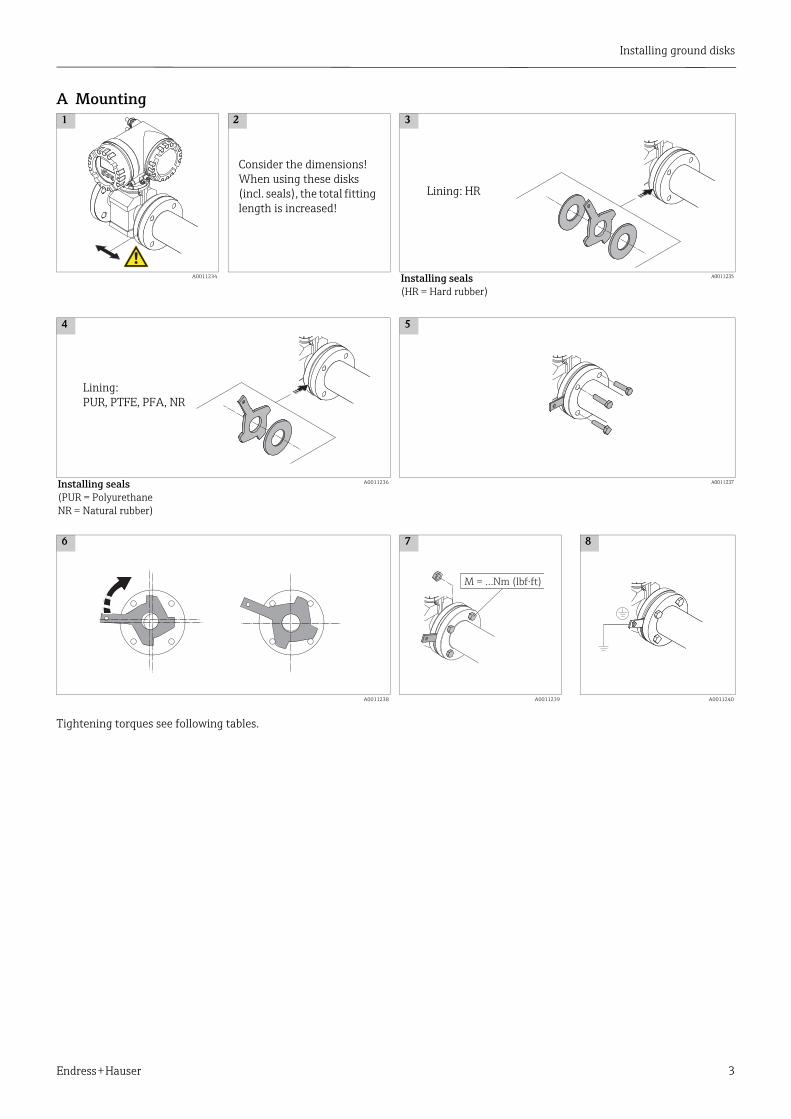
A Mounting
Tightening torques see following tables.
1 2 3
A0011234 Installing seals(HR = Hard rubber)
A0011235
4 5
Installing seals(PUR = PolyurethaneNR = Natural rubber)
A0011236 A0011237
6 7 8
A0011238 A0011239 A0011240
Lining: HR
Lining:PUR, PTFE, PFA, NR
M = …Nm (lbf·ft)
Consider the dimensions! When using these disks (incl. seals), the total fitting length is increased!
Installing ground disks
4 Endress + Hauser
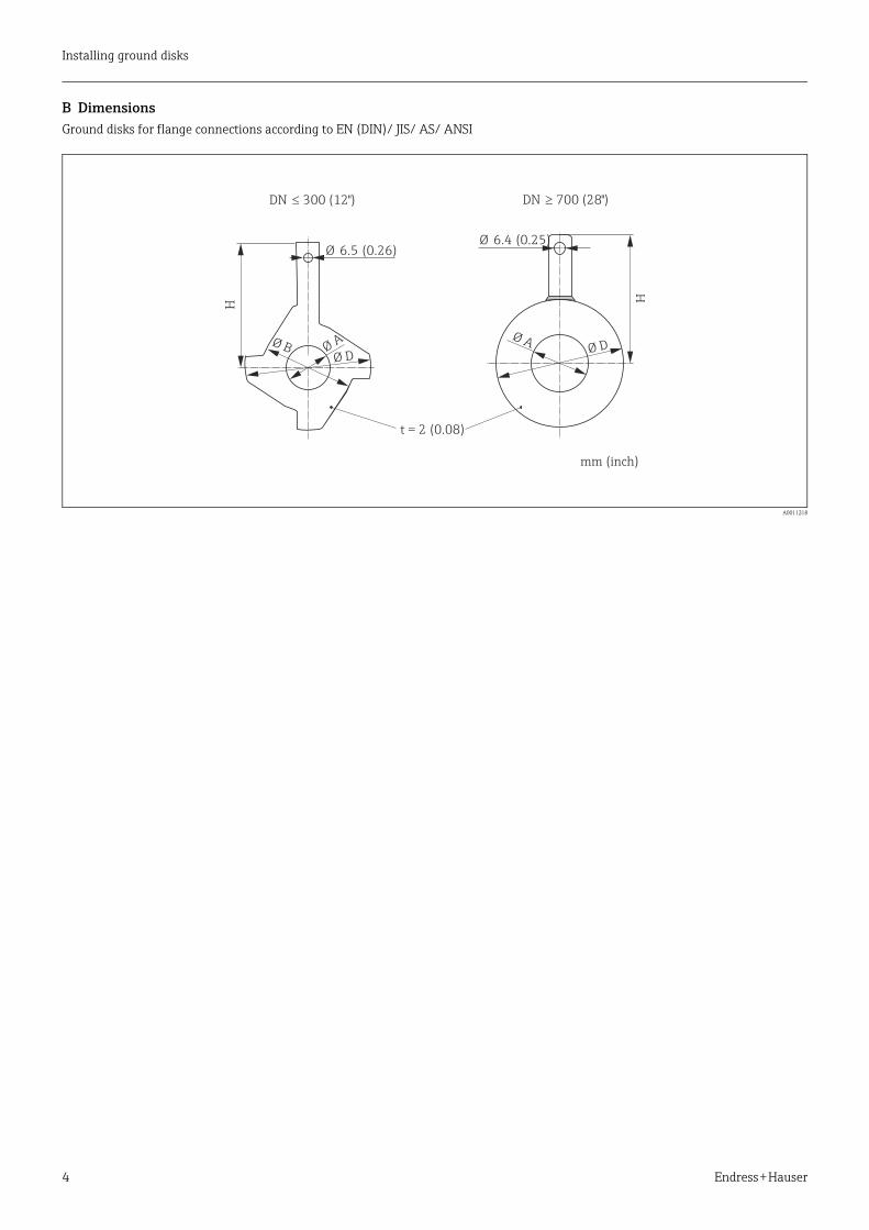
B DimensionsGround disks for flange connections according to EN (DIN)/ JIS/ AS/ ANSI
A0011218
H
Ø BØ D
ØA
H
Ø DØ A
DN � 300 (12")
mm (inch)
Ø 6.5 (0.26)Ø 6.4 (0.25)
DN � 700 (28")
t = 2 (0.08)
Installing ground disks
Endress + Hauser 5
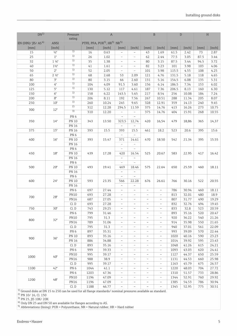
DN1) Pressure rating
A B D H
EN (DIN)/ JIS/ AS 4) ANSI PTFE, PFA, PUR5), HR5) NR 5)
[mm] [inch] [mm] [inch] [mm] [inch] [mm] [inch] [mm] [inch] [mm] [inch]15 ½" 1) 16 0.63 – – 43 1.69 61.5 2.42 73 2.8725 1" 1) 26 1.02 – – 62 2.44 77.5 3.05 87.5 3.4432 1 ¼" 1) 35 1.38 – – 80 3.15 87.5 3.44 94.5 3.7240 1½" 1) 41 1.61 – – 82 3.23 101 3.98 103 4.0650 2" 1) 52 2.05 – – 101 3.98 115.5 4.55 108 4.2565 2 ½" 1) 68 2.68 53 2.09 121 4.76 131.5 5.18 118 4.6580 3" 1) 80 3.15 66 2.60 131 5.16 154.5 6.08 135 5.31
100 4" 1) 104 4.09 91.5 3.60 156 6.14 186.5 7.34 153 6.02125 5" 1) 130 5.12 117 4.61 187 7.36 206.5 8.13 160 6.30150 6" 1) 158 6.22 143.5 5.65 217 8.54 256 10.08 184 7.24200 8" 1) 206 8.11 192 7.56 267 10.51 288 11.34 205 8.07250 10" 1) 260 10.24 245 9.65 328 12.91 359 14.13 240 9.45
300 12" 2) 312 12.28 294.5 11.59 375 14.76 413 16.26 273 10.75 3) 310 12.20 – – 375 14.76 404 15.91 268 10.55
350 14" PN 6
343 13.50 – –
420 16,54 479 18,86 365 14,37PN 10 323,5 12,74PN 16 – –
375 15" PN 16 393 15.5 393 15.5 461 18.2 523 20.6 395 15.6
400 16" PN 6
393 15.47– –
470 18.50 542 21.34 395 15.55PN 10 371 14.61PN 16 – –
450 18" PN 6
439 17.28– –
525 20.67 583 22.95 417 16.42PN 10 420 16.54PN 16 – –
500 20" PN 6
493 19.41– –
575 22.64 650 25.59 460 18.11PN 10 469 18.46PN 16 – –
600 24" PN 6
593 23.35– –
676 26.61 766 30.16 522 20.55PN 10 566 22.28PN 16 – –
700 28"
PN 6 697 27.44 – – – – 786 30.94 460 18.11PN10 693 27.28 – – – – 813 32.01 480 18.9PN16 687 27.05 – – – – 807 31.77 490 19.29Cl. D 693 27.28 – – – – 832 32.76 494 19.45
750 30" Cl. D 743 29.25 – – – – 833 32.8 523 20.59
800 32"
PN 6 799 31.46 – – – – 893 35.16 520 20.47PN10 795 31.3 – – – – 920 36.22 540 21.26PN16 789 31.06 – – – – 914 35.98 550 21.65Cl. D 795 31.3 – – – – 940 37.01 561 22.09
900 36"
PN 6 897 35.31 – – – – 993 39.09 570 22.44PN 10 893 35.16 – – – – 1020 40.16 590 23.23PN 16 886 34.88 – – – – 1014 39.92 595 23.43Cl. D 893 35.16 – – – – 1048 41.26 615 24.21
1000 40"
PN 6 999 39.33 – – – – 1093 43.03 620 24.41PN10 995 39.17 – – – – 1127 44.37 650 25.59PN16 988 38.9 – – – – 1131 44.53 660 25.98Cl. D 995 39.17 – – – – 1163 45.79 675 26.57
1100 42" PN 6 1044 41.1 – – – – 1220 48.03 704 27.72
1200 48"
PN 6 1203 47.36 – – – – 1310 51.57 733 28.86PN10 1196 47.09 – – – – 1344 52.91 760 29.92PN16 1196 47.09 – – – – 1385 54.53 786 30.94Cl. D 1188 46.77 – – – – 1345 52.95 775 30.51
1) Ground disks at DN 15 to 250 can be used for all flange standards/ nominal pressures available as standard.2) PN 10/ 16, Cl. 1503) PN 25, JIS 10K/ 20K4) Only DN 25 and DN 50 are available for flanges according to AS.5) Abbreviations (lining): PUR = Polyurethane, NR = Natural rubber, HR = Hard rubber

Installing ground disks
6 Endress + Hauser
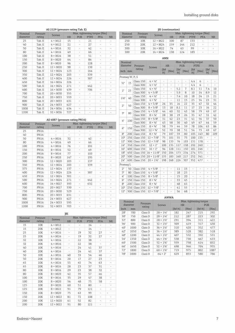
C Tightening torquesAbbreviations (lining): PUR = Polyurethane, NR = Natural rubber, HR = Hard rubber
EN (DIN) (pressure rating in [bar])Nominal diameter
Pressure rating Screws
Max. tightening torque [Nm]HR PUR PTFE PFA NR
Promag W, P, S15 40 4 × M12 - - 11 - –25 40 4 × M12 - 15 26 20 –32 40 4 × M16 - 24 41 35 –40 40 4 × M16 - 31 52 47 –50 40 4 × M16 48 40 65 59 –
65* 16 4 × M16 32 27 87 80 1165 40 8 × M16 32 27 43 40 –80 16 8 × M16 40 34 53 48 1380 40 8 × M16 40 34 53 48 –
100 16 8 × M16 43 36 57 51 14100 40 8 × M20 59 50 78 70 –125 16 8 × M16 56 48 75 67 19125 40 8 × M24 83 71 111 99 –150 16 8 × M20 74 63 99 85 27150 40 8 × M24 104 88 136 120 –200 10 8 × M20 106 91 141 101 –200 16 12 × M20 70 61 94 67 28200 25 12 × M24 104 92 138 105 –250 10 12 × M20 82 71 110 - 27250 16 12 × M24 98 85 131 - –250 25 12 × M27 150 134 200 - –300 10 12 × M20 94 81 125 - 34300 16 12 × M24 134 118 179 - –300 25 16 × M27 153 138 204 - –350 6 12 × M20 111 120 - - –350 10 16 × M20 112 118 188 - 47350 16 16 × M24 152 165 254 - –350 25 16 × M30 227 252 380 - –400 6 16 × M20 90 98 - - –400 10 16 × M24 151 167 260 - 65400 16 16 × M27 193 215 330 - –400 25 16 × M33 289 326 488 - –450 6 16 × M20 112 126 - - –450 10 20 × M24 153 133 235 - 59450 16 20 × M27 198 196 300 - –450 25 20 × M33 256 253 385 - –500 6 20 × M20 119 123 - - –500 10 20 × M24 155 171 265 - 66500 16 20 × M30 275 300 448 - –500 25 20 × M33 317 360 533 - –600 6 20 × M24 139 147 - - –600 10 20 × M27 206 219 345 - 93
600* 16 20 × M33 415 443 658 - –600 25 20 × M36 431 516 731 - –700 6 24 × M24 148 139 - - -700 10 24 × M27 246 246 - - -700 16 24 × M33 278 318 - - -700 25 24 × M39 449 507 - - -800 6 24 × M27 206 182 - - -800 10 24 × M30 331 316 - - -800 16 24 × M36 369 385 - - -800 25 24 × M45 664 721 - - -900 6 24 × M27 230 637 - - -900 10 28 × M30 316 307 - - -900 16 28 × M36 353 398 - - -900 25 28 × M45 690 716 - - -
1000 6 28 × M27 218 208 - - -1000 10 28 × M33 402 405 - - -1000 16 28 × M39 502 518 - - -1000 25 28 × M52 970 971 - - -1200 6 32 × M30 319 299 - - -1200 10 32 × M36 564 568 - - -1200 16 32 × M45 701 753 - - -1400 6 36 × M33 430 398 - - -
EN (DIN) (continuation)Nominal diameter
Pressure rating Screws
Max. tightening torque [Nm]HR PUR PTFE PFA NR
Promag W, P, S1400 10 36 × M39 654 618 - - -1400 16 36 × M45 729 762 - - -1600 6 40 × M33 440 417 - - -1600 10 40 × M45 946 893 - - -1600 16 40 × M52 1007 1100 - - -1800 6 44 × M36 547 521 - - -1800 10 44 × M45 961 895 - - -1800 16 44 × M52 1108 1003 - - -2000 6 48 × M39 629 605 - - -2000 10 48 × M45 1047 1092 - - -2000 16 48 × M56 1324 1261 - - -
Promag L50 16 4 × M16 - 15 - - -
65* 16 8 × M16 - 10 - - -80 16 8 × M16 - 15 - - -
100 16 8 × M16 - 20 - - -125 16 8 × M16 - 30 - - -150 16 8 × M20 - 50 - - -200 10 8 × M20 - 65 - - -250 10 12 × M20 - 50 - - -300 10 12 × M20 - 55 - - -
* Designed acc. to EN 1092-1 (not to DIN 2501)
Installing ground disks
Endress + Hauser 7
AS 2129 (pressure rating Tab. E)Nominal diameter
Pressure rating Screws
Max. tightening torque [Nm]HR PUR PTFE PFA NR
25 Tab. E 4 × M12 15 - 21 - -40 Tab. E 4 × M12 21 - 27 - -50 Tab. E 4 × M16 32 - 42 - -80 Tab. E 4 × M16 49 - 66 - -
100 Tab. E 8 × M16 38 - 51 - -150 Tab. E 8 × M20 64 - 86 - -200 Tab. E 8 × M20 96 - 128 - -250 Tab. E 12 × M20 98 - 130 - -300 Tab. E 12 × M24 123 - 164 - -350 Tab. E 12 × M24 203 - 339 - -400 Tab. E 12 × M24 226 - 387 - -450 Tab. E 16 × M24 226 - - - -500 Tab. E 16 × M24 271 - 442 - -600 Tab. E 16 × M30 439 - 706 - -700 Tab. E 20 × M30 355 - - - -750 Tab. E 20 × M33 559 - - - -800 Tab. E 20 × M33 631 - - - -900 Tab. E 24 × M33 627 - - - -
1000 Tab. E 24 × M36 634 - - - -1200 Tab. E 32 × M36 727 - - - -
AS 4087 (pressure rating PN16)Nominal diameter
Pressure rating Screws
Max. tightening torque [Nm]HR PUR PTFE PFA NR
25 PN16 - - - - - -40 PN16 - - - - - -50 PN16 4 × M16 32 - 42 - -80 PN16 4 × M16 49 - 66 - -
100 PN16 4 × M16 76 - 101 - -150 PN16 8 × M16 52 - 69 - -200 PN16 8 × M16 77 - 103 - -250 PN16 8 × M20 147 - 195 - -300 PN16 12 × M20 103 - 137 - -350 PN16 12 × M24 203 - 339 - -375 PN16 12 × M24 137 - - - -400 PN16 12 × M24 226 - 387 - -450 PN16 12 × M24 301 - - - -500 PN16 16 × M24 271 - 442 - -600 PN16 16 × M27 393 - 632 - -700 PN16 20 × M27 330 - - - -750 PN16 20 × M30 529 - - - -800 PN16 20 × M33 631 - - - -900 PN16 24 × M33 627 - - - -
1000 PN16 24 × M33 595 - - - -1200 PN16 32 × M33 703 - - - -
JISNominal diameter
Pressure rating Screws
Max. tightening torque [Nm]HR PUR PTFE PFA NR
15 10K 4 × M12 - - 14 - -15 20K 4 × M12 - - 14 - -25 10K 4 × M16 - 19 32 27 -25 20K 4 × M16 - 19 32 27 -32 10K 4 × M16 - 22 38 - -32 20K 4 × M16 - 22 38 - -40 10K 4 × M16 - 24 41 37 -40 20K 4 × M16 - 24 41 37 -50 10K 4 × M16 40 33 54 46 -50 20K 8 × M16 20 17 27 23 -65 10K 4 × M16 55 45 74 63 -65 20K 8 × M16 28 23 37 31 -80 10K 8 × M16 29 23 38 32 -80 20K 8 × M20 42 35 57 46 -
100 10K 8 × M16 35 29 47 38 -100 20K 8 × M20 56 48 75 58 -125 10K 8 × M20 60 51 80 - -125 20K 8 × M22 91 79 121 - -150 10K 8 × M20 75 63 99 - -150 20K 12 × M22 81 72 108 - -200 10K 12 × M20 61 52 82 - -200 20K 12 × M22 91 80 121 - -
JIS (continuation)Nominal diameter
Pressure rating Screws
Max. tightening torque [Nm]HR PUR PTFE PFA NR
250 10K 12 × M22 100 87 133 - -250 20K 12 × M24 159 144 212 - -300 10K 16 × M22 74 63 99 - -300 20K 16 × M24 138 124 183 - -
ANSINominal diameter Pressure
rating Screws
Max. tightening torqueHR PUR PTFE PFA
Inch mm [lbf ft] [Nm] [lbf
ft] [Nm] [lbf ft] [Nm] [lbf
ft] [Nm]
Promag W, P, S
½" 15Class 150 4 × ½" - - - - 4.4 6 - -Class 300 4 × ½" - - - - 4.4 6 - -
1" 25Class 150 4 × ½" - - 5.2 7 8.1 11 7.4 10Class 300 4 × 5/8" - - 5.9 8 10 14 8.9 12
1½" 40Class 150 4 × ½" - - 7.4 10 18 24 15 21Class 300 4 × ¾" - - 11 15 25 34 23 31
2" 50Class 150 4 × 5/8" 26 35 16 22 35 47 32 44Class 300 8 × 5/8" 13 18 8.1 11 17 23 16 22
3" 80Class 150 4 × 5/8" 44 60 32 43 58 79 49 67Class 300 8 × ¾" 28 38 19 26 35 47 31 42
4" 100Class 150 8 × 5/8" 31 42 23 31 41 56 37 50Class 300 8 × ¾" 43 58 30 40 49 67 44 59
6" 150Class 150 8 × ¾" 58 79 44 59 78 106 63 86Class 300 12 × ¾" 52 70 38 51 54 73 49 67
8" 200 Class 150 8 × ¾" 79 107 59 80 105 143 80 10910" 250 Class 150 12 × 7/8" 75 101 55 75 100 135 - -12" 300 Class 150 12 × 7/8" 98 133 76 103 131 178 - -14" 350 Class 150 12 × 1" 100 135 117 158 192 260 - -16" 400 Class 150 16 × 1" 94 128 111 150 181 246 - -18" 450 Class 150 16 × 11/8" 150 204 173 234 274 371 - -20" 500 Class 150 20 × 11/8" 135 183 160 217 252 341 - -24" 600 Class 150 20 × 1¼" 198 268 226 307 352 477 - -
Promag L2" 50 Class 150 4 × 5/8" - - 11 15 - - - -3" 80 Class 150 4 × 5/8" - - 18 25 - - - -4" 100 Class 150 8 × 5/8" - - 15 20 - - - -6" 150 Class 150 8 × ¾" - - 33 45 - - - -8" 200 Class 150 8 × ¾" - - 48 65 - - - -
10" 250 Class 150 12 × 7/8" - - 41 55 - - - -12" 300 Class 150 12 × 7/8" - - 56 68 - - - -
AWWANominal diameter Pressure
rating ScrewsMax. tightening torqueHR PUR
Inch mm [lbf ft] [Nm] [lbf ft] [Nm]28" 700 Class D 28 × 1¼" 182 247 215 29230" 750 Class D 28 × 1¼" 212 287 223 30232" 800 Class D 28 × 1½" 291 394 311 42236" 900 Class D 32 × 1½" 309 419 317 43040" 1000 Class D 36 × 1½" 310 420 352 47742" 1050 Class D 36 × 1½" 389 528 382 51848" 1200 Class D 44 × 1½" 407 552 392 53154" 1350 Class D 44 × 1¾" 538 730 467 63360" 1500 Class D 52 × 1¾" 559 758 614 83266" 1650 Class D 52 × 1¾" 698 946 704 95572" 1800 Class D 60 × 1¾" 719 975 802 108778" 2000 Class D 64 × 2" 629 853 580 786

Installing ground disks
8 Endress + Hauser

Products Solutions Services
EinbauanleitungEinbau von ErdungsscheibenPromag W, P, S, L, E
Die Einbauanleitung ist für folgendes Zubehörteil gültig:
Übersicht der installationsberechtigten Personen
Die Berechtigung zur Durchführung einer Installation ist von der Zulassung des Messgeräts abhängig. Die Tabelle zeigt den jeweils berechtigten Personenkreis.
Die Person, die eine Installation vornimmt, übernimmt die Verantwortung für die Sicherheit während der Arbeiten, die Qualität der Ausführung und die Sicherheit des Geräts nach der Installation.
Bestellnummer Gerätekomponente
DK5GD-***** 1 × Erdungsscheibe
Zulassung des Messgeräts Installationsberechtigter Personenkreis
ohne Zulassung 1, 2, 3
mit Zulassung (z.B. IECEx, ATEX, CSA) 1, 2, 3
1 Ausgebildete Fachkraft des Kunden2 Von Endress+Hauser autorisierter Servicetechniker3 Endress+Hauser (Messgerät an Hersteller zurücksenden)
HINWEIS
EA00070D/06/A2/13.1471258984
Einbau von Erdungsscheiben
2 Endress + Hauser
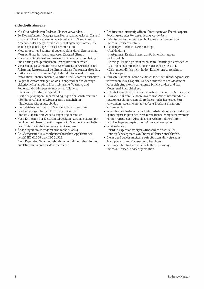
Sicherheitshinweise
• Nur Originalteile von Endress+Hauser verwenden.• Bei Ex-zertifizierten Messgeräten: Nur in spannungslosem Zustand
(nach Berücksichtigung einer Wartezeit von 10 Minuten nach Abschalten der Energiezufuhr) oder in Umgebungen öffnen, die keine explosionsfähige Atmosphäre enthalten.
• Messgerät unter Spannung! Lebensgefahr durch Stromschlag. Messgerät nur im spannungslosen Zustand öffnen.
• Vor einem Geräteausbau: Prozess in sicheren Zustand bringen und Leitung von gefährlichen Prozessstoffen befreien.
• Verbrennungsgefahr durch heiße Oberflächen! Vor Arbeitsbeginn: Anlage und Messgerät auf berührungssichere Temperatur abkühlen.
• Nationale Vorschriften bezüglich der Montage, elektrischen Installation, Inbetriebnahme, Wartung und Reparatur einhalten.
• Folgende Anforderungen an das Fachpersonal für Montage, elektrische Installation, Inbetriebnahme, Wartung und Reparatur der Messgeräte müssen erfüllt sein: –In Gerätesicherheit ausgebildet–Mit den jeweiligen Einsatzbedingungen der Geräte vertraut–Bei Ex-zertifizierten Messgeräten zusätzlich im
Explosionsschutz ausgebildet • Die Betriebsanleitung zum Messgerät ist zu beachten.• Beschädigungsgefahr elektronischer Bauteile!
Eine ESD-geschützte Arbeitsumgebung herstellen. • Nach Entfernen der Elektronikabdeckung: Stromschlaggefahr
durch aufgehobenen Berührungsschutz! Messgerät ausschalten, bevor interne Abdeckungen entfernt werden.
• Änderungen am Messgerät sind nicht zulässig.• Bei Messgeräten in sicherheitstechnischen Applikationen
gemäß IEC 61508 bzw. IEC 61511: Nach Reparatur Neuinbetriebnahme gemäß Betriebsanleitung durchführen. Reparatur dokumentieren.
• Gehäuse nur kurzzeitig öffnen. Eindringen von Fremdkörpern, Feuchtigkeit oder Verunreinigung vermeiden.
• Defekte Dichtungen nur durch Original-Dichtungen von Endress+Hauser ersetzen.
• Dichtungen (nicht im Lieferumfang):–Auskleidung
Hartgummi: Es sind immer zusätzliche Dichtungen erforderlich Sonstige: Es sind grundsätzlich keine Dichtungen erforderlich
–DIN-Flansche: nur Dichtungen nach DIN EN 1514-1.–Dichtungen dürfen nicht in den Rohrleitungsquerschnitt
hineinragen.• Kurzschlussgefahr! Keine elektrisch leitenden Dichtungsmassen
verwenden (z.B. Graphit)! Auf der Innenseite des Messrohrs kann sich eine elektrisch leitende Schicht bilden und das Messsignal kurzschließen.
• Defekte Gewinde erfordern eine Instandsetzung des Messgeräts.• Gewinde (z.B. von Elektronikraum-und Anschlussraumdeckel)
müssen geschmiert sein. Säurefreies, nicht härtendes Fett verwenden, sofern keine abriebfeste Trockenschmierung vorhanden ist.
• Wenn bei den Installationsarbeiten Abstände reduziert oder die Spannungsfestigkeit des Messgeräts nicht sichergestellt werden kann: Prüfung nach Abschluss der Arbeiten durchführen (z.B. Hochspannungstest gemäß Herstellerangaben).
• Servicestecker: –nicht in explosionsfähiger Atmosphäre anschließen.–nur an Servicegeräte von Endress+Hauser anschließen.
• Die in der Betriebsanleitung aufgeführten Hinweise zum Transport und zur Rücksendung beachten.
• Bei Fragen kontaktieren Sie bitte Ihre zuständige Endress+Hauser Serviceorganisation.
Einbau von Erdungsscheiben
Endress + Hauser 3
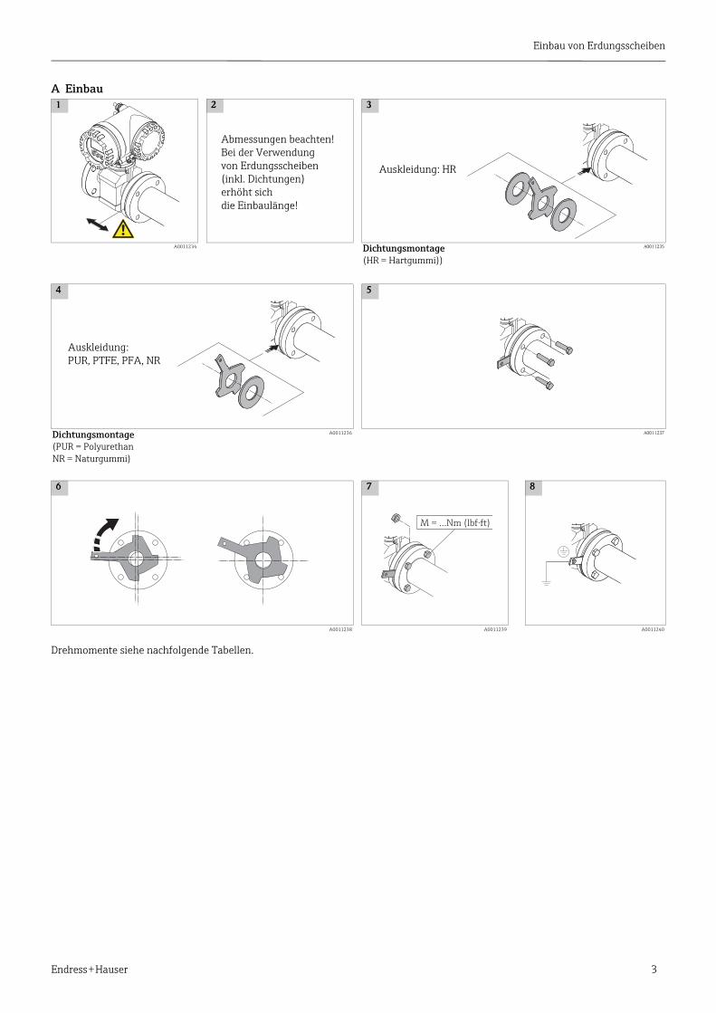
A Einbau
Drehmomente siehe nachfolgende Tabellen.
1 2 3
A0011234 Dichtungsmontage(HR = Hartgummi))
A0011235
4 5
Dichtungsmontage(PUR = PolyurethanNR = Naturgummi)
A0011236 A0011237
6 7 8
A0011238 A0011239 A0011240
Auskleidung: HR
Auskleidung:PUR, PTFE, PFA, NR
M = …Nm (lbf·ft)
Abmessungen beachten!Bei der Verwendung von Erdungsscheiben(inkl. Dichtungen)erhöht sich die Einbaulänge!

Einbau von Erdungsscheiben
4 Endress + Hauser
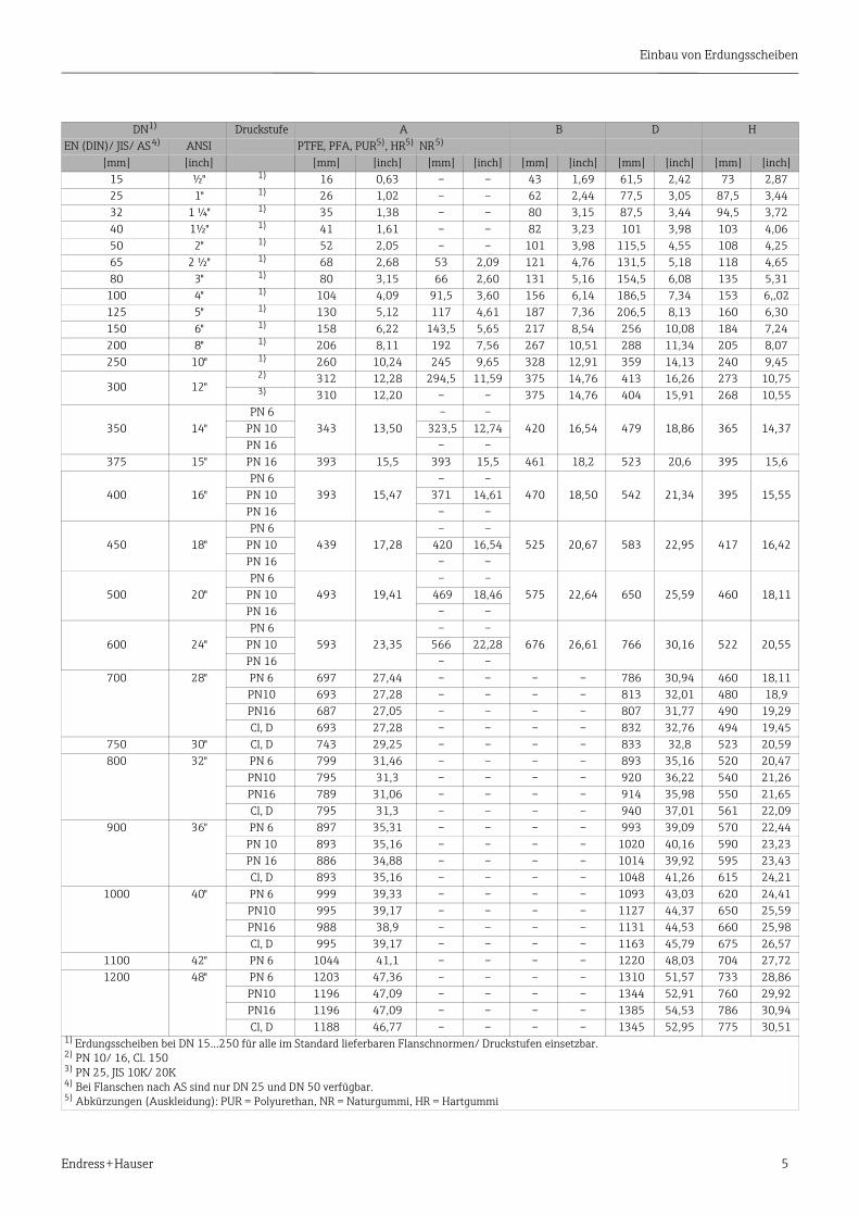
B AbmessungenErdungsscheiben für Flanschanschlüsse gemäß EN (DIN)/ JIS/ AS/ ANSI
A0011218
H
Ø BØ D
ØA
H
Ø DØ A
DN � 300 (12")
mm (inch)
Ø 6.5 (0.26)Ø 6.4 (0.25)
DN � 700 (28")
t = 2 (0.08)
Einbau von Erdungsscheiben
Endress + Hauser 5
DN1) Druckstufe A B D HEN (DIN)/ JIS/ AS 4) ANSI PTFE, PFA, PUR5), HR5) NR 5)
[mm] [inch] [mm] [inch] [mm] [inch] [mm] [inch] [mm] [inch] [mm] [inch]15 ½" 1) 16 0,63 – – 43 1,69 61,5 2,42 73 2,8725 1" 1) 26 1,02 – – 62 2,44 77,5 3,05 87,5 3,4432 1 ¼" 1) 35 1,38 – – 80 3,15 87,5 3,44 94,5 3,7240 1½" 1) 41 1,61 – – 82 3,23 101 3,98 103 4,0650 2" 1) 52 2,05 – – 101 3,98 115,5 4,55 108 4,2565 2 ½" 1) 68 2,68 53 2,09 121 4,76 131,5 5,18 118 4,6580 3" 1) 80 3,15 66 2,60 131 5,16 154,5 6,08 135 5,31
100 4" 1) 104 4,09 91,5 3,60 156 6,14 186,5 7,34 153 6,,02125 5" 1) 130 5,12 117 4,61 187 7,36 206,5 8,13 160 6,30150 6" 1) 158 6,22 143,5 5,65 217 8,54 256 10,08 184 7,24200 8" 1) 206 8,11 192 7,56 267 10,51 288 11,34 205 8,07250 10" 1) 260 10,24 245 9,65 328 12,91 359 14,13 240 9,45
300 12" 2) 312 12,28 294,5 11,59 375 14,76 413 16,26 273 10,75 3) 310 12,20 – – 375 14,76 404 15,91 268 10,55
350 14" PN 6
343 13,50 – –
420 16,54 479 18,86 365 14,37PN 10 323,5 12,74PN 16 – –
375 15" PN 16 393 15,5 393 15,5 461 18,2 523 20,6 395 15,6
400 16" PN 6
393 15,47– –
470 18,50 542 21,34 395 15,55PN 10 371 14,61PN 16 – –
450 18" PN 6
439 17,28– –
525 20,67 583 22,95 417 16,42PN 10 420 16,54PN 16 – –
500 20" PN 6
493 19,41– –
575 22,64 650 25,59 460 18,11PN 10 469 18,46PN 16 – –
600 24" PN 6
593 23,35– –
676 26,61 766 30,16 522 20,55PN 10 566 22,28PN 16 – –
700 28" PN 6 697 27,44 – – – – 786 30,94 460 18,11PN10 693 27,28 – – – – 813 32,01 480 18,9PN16 687 27,05 – – – – 807 31,77 490 19,29Cl, D 693 27,28 – – – – 832 32,76 494 19,45
750 30" Cl, D 743 29,25 – – – – 833 32,8 523 20,59800 32" PN 6 799 31,46 – – – – 893 35,16 520 20,47
PN10 795 31,3 – – – – 920 36,22 540 21,26PN16 789 31,06 – – – – 914 35,98 550 21,65Cl, D 795 31,3 – – – – 940 37,01 561 22,09
900 36" PN 6 897 35,31 – – – – 993 39,09 570 22,44PN 10 893 35,16 – – – – 1020 40,16 590 23,23PN 16 886 34,88 – – – – 1014 39,92 595 23,43Cl, D 893 35,16 – – – – 1048 41,26 615 24,21
1000 40" PN 6 999 39,33 – – – – 1093 43,03 620 24,41PN10 995 39,17 – – – – 1127 44,37 650 25,59PN16 988 38,9 – – – – 1131 44,53 660 25,98Cl, D 995 39,17 – – – – 1163 45,79 675 26,57
1100 42" PN 6 1044 41,1 – – – – 1220 48,03 704 27,721200 48" PN 6 1203 47,36 – – – – 1310 51,57 733 28,86
PN10 1196 47,09 – – – – 1344 52,91 760 29,92PN16 1196 47,09 – – – – 1385 54,53 786 30,94Cl, D 1188 46,77 – – – – 1345 52,95 775 30,51
1) Erdungsscheiben bei DN 15…250 für alle im Standard lieferbaren Flanschnormen/ Druckstufen einsetzbar.2) PN 10/ 16, Cl. 1503) PN 25, JIS 10K/ 20K4) Bei Flanschen nach AS sind nur DN 25 und DN 50 verfügbar.5) Abkürzungen (Auskleidung): PUR = Polyurethan, NR = Naturgummi, HR = Hartgummi
Einbau von Erdungsscheiben
6 Endress + Hauser
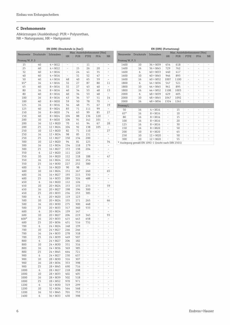
C DrehmomenteAbkürzungen (Auskleidung): PUR = Polyurethan, NR = Naturgummi, HR = Hartgummi
EN (DIN) (Druckstufe in [bar])
Nennweite Druckstufe SchraubenMax. Anziehdrehmoment [Nm]
HR PUR PTFE PFA NRPromag W, P, S
15 40 4 × M12 - - 11 - –25 40 4 × M12 - 15 26 20 –32 40 4 × M16 - 24 41 35 –40 40 4 × M16 - 31 52 47 –50 40 4 × M16 48 40 65 59 –
65* 16 4 × M16 32 27 87 80 1165 40 8 × M16 32 27 43 40 –80 16 8 × M16 40 34 53 48 1380 40 8 × M16 40 34 53 48 –
100 16 8 × M16 43 36 57 51 14100 40 8 × M20 59 50 78 70 –125 16 8 × M16 56 48 75 67 19125 40 8 × M24 83 71 111 99 –150 16 8 × M20 74 63 99 85 27150 40 8 × M24 104 88 136 120 –200 10 8 × M20 106 91 141 101 –200 16 12 × M20 70 61 94 67 28200 25 12 × M24 104 92 138 105 –250 10 12 × M20 82 71 110 - 27250 16 12 × M24 98 85 131 - –250 25 12 × M27 150 134 200 - –300 10 12 × M20 94 81 125 - 34300 16 12 × M24 134 118 179 - –300 25 16 × M27 153 138 204 - –350 6 12 × M20 111 120 - - –350 10 16 × M20 112 118 188 - 47350 16 16 × M24 152 165 254 - –350 25 16 × M30 227 252 380 - –400 6 16 × M20 90 98 - - –400 10 16 × M24 151 167 260 - 65400 16 16 × M27 193 215 330 - –400 25 16 × M33 289 326 488 - –450 6 16 × M20 112 126 - - –450 10 20 × M24 153 133 235 - 59450 16 20 × M27 198 196 300 - –450 25 20 × M33 256 253 385 - –500 6 20 × M20 119 123 - - –500 10 20 × M24 155 171 265 - 66500 16 20 × M30 275 300 448 - –500 25 20 × M33 317 360 533 - –600 6 20 × M24 139 147 - - –600 10 20 × M27 206 219 345 - 93
600* 16 20 × M33 415 443 658 - –600 25 20 × M36 431 516 731 - –700 6 24 × M24 148 139 - - -700 10 24 × M27 246 246 - - -700 16 24 × M33 278 318 - - -700 25 24 × M39 449 507 - - -800 6 24 × M27 206 182 - - -800 10 24 × M30 331 316 - - -800 16 24 × M36 369 385 - - -800 25 24 × M45 664 721 - - -900 6 24 × M27 230 637 - - -900 10 28 × M30 316 307 - - -900 16 28 × M36 353 398 - - -900 25 28 × M45 690 716 - - -
1000 6 28 × M27 218 208 - - -1000 10 28 × M33 402 405 - - -1000 16 28 × M39 502 518 - - -1000 25 28 × M52 970 971 - - -1200 6 32 × M30 319 299 - - -1200 10 32 × M36 564 568 - - -1200 16 32 × M45 701 753 - - -1400 6 36 × M33 430 398 - - -
EN (DIN) (Fortsetzung)
Nennweite Druckstufe SchraubenMax. Anziehdrehmoment [Nm]
HR PUR PTFE PFA NRPromag W, P, S
1400 10 36 × M39 654 618 - - -1400 16 36 × M45 729 762 - - -1600 6 40 × M33 440 417 - - -1600 10 40 × M45 946 893 - - -1600 16 40 × M52 1007 1100 - - -1800 6 44 × M36 547 521 - - -1800 10 44 × M45 961 895 - - -1800 16 44 × M52 1108 1003 - - -2000 6 48 × M39 629 605 - - -2000 10 48 × M45 1047 1092 - - -2000 16 48 × M56 1324 1261 - - -
Promag L50 16 4 × M16 - 15 - - -
65* 16 8 × M16 - 10 - - -80 16 8 × M16 - 15 - - -
100 16 8 × M16 - 20 - - -125 16 8 × M16 - 30 - - -150 16 8 × M20 - 50 - - -200 10 8 × M20 - 65 - - -250 10 12 × M20 - 50 - - -300 10 12 × M20 - 55 - - -
* Auslegung gemäß EN 1092-1 ((nicht nach DIN 2501)
Einbau von Erdungsscheiben
Endress + Hauser 7
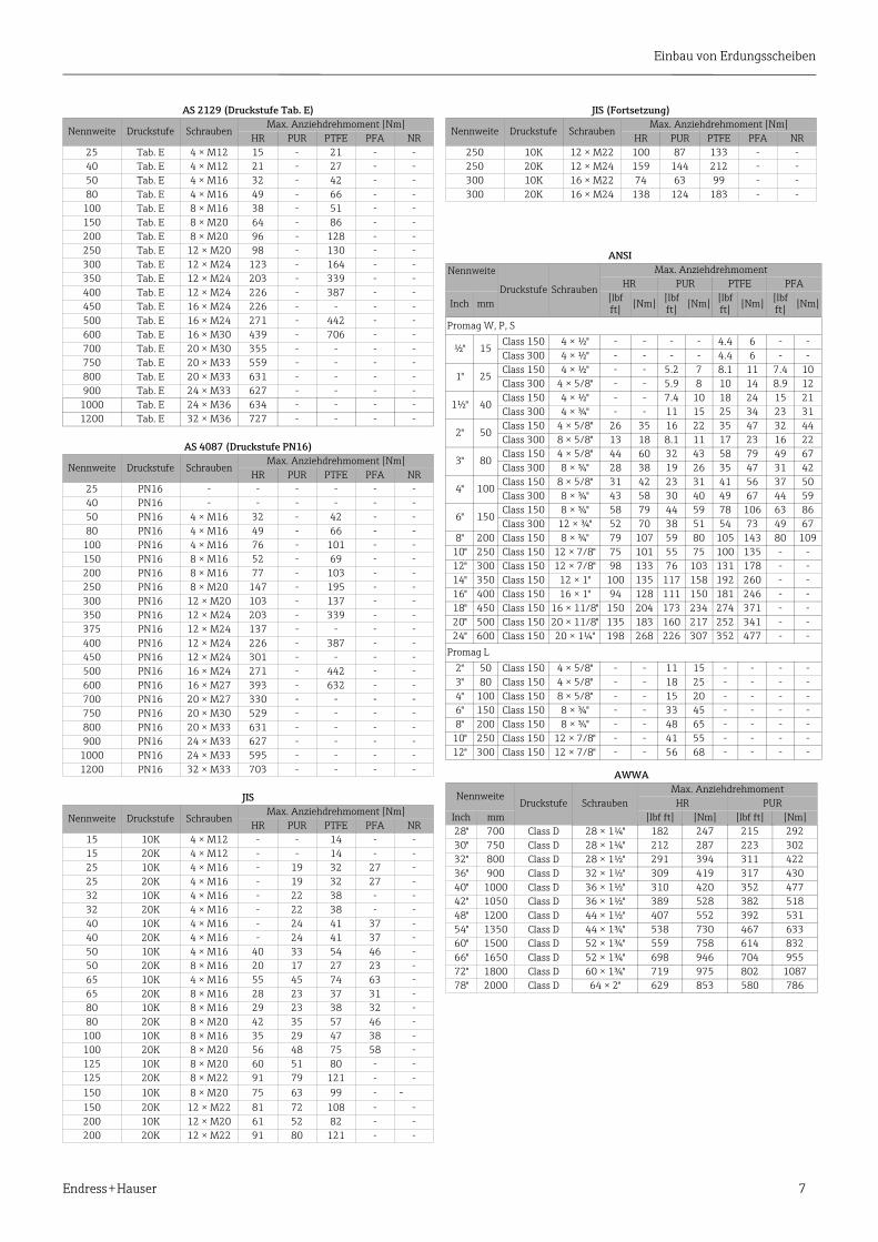
AS 2129 (Druckstufe Tab. E)
Nennweite Druckstufe SchraubenMax. Anziehdrehmoment [Nm]
HR PUR PTFE PFA NR25 Tab. E 4 × M12 15 - 21 - -40 Tab. E 4 × M12 21 - 27 - -50 Tab. E 4 × M16 32 - 42 - -80 Tab. E 4 × M16 49 - 66 - -
100 Tab. E 8 × M16 38 - 51 - -150 Tab. E 8 × M20 64 - 86 - -200 Tab. E 8 × M20 96 - 128 - -250 Tab. E 12 × M20 98 - 130 - -300 Tab. E 12 × M24 123 - 164 - -350 Tab. E 12 × M24 203 - 339 - -400 Tab. E 12 × M24 226 - 387 - -450 Tab. E 16 × M24 226 - - - -500 Tab. E 16 × M24 271 - 442 - -600 Tab. E 16 × M30 439 - 706 - -700 Tab. E 20 × M30 355 - - - -750 Tab. E 20 × M33 559 - - - -800 Tab. E 20 × M33 631 - - - -900 Tab. E 24 × M33 627 - - - -
1000 Tab. E 24 × M36 634 - - - -1200 Tab. E 32 × M36 727 - - - -
AS 4087 (Druckstufe PN16)
Nennweite Druckstufe SchraubenMax. Anziehdrehmoment [Nm]
HR PUR PTFE PFA NR25 PN16 - - - - - -40 PN16 - - - - - -50 PN16 4 × M16 32 - 42 - -80 PN16 4 × M16 49 - 66 - -
100 PN16 4 × M16 76 - 101 - -150 PN16 8 × M16 52 - 69 - -200 PN16 8 × M16 77 - 103 - -250 PN16 8 × M20 147 - 195 - -300 PN16 12 × M20 103 - 137 - -350 PN16 12 × M24 203 - 339 - -375 PN16 12 × M24 137 - - - -400 PN16 12 × M24 226 - 387 - -450 PN16 12 × M24 301 - - - -500 PN16 16 × M24 271 - 442 - -600 PN16 16 × M27 393 - 632 - -700 PN16 20 × M27 330 - - - -750 PN16 20 × M30 529 - - - -800 PN16 20 × M33 631 - - - -900 PN16 24 × M33 627 - - - -
1000 PN16 24 × M33 595 - - - -1200 PN16 32 × M33 703 - - - -
JIS
Nennweite Druckstufe SchraubenMax. Anziehdrehmoment [Nm]
HR PUR PTFE PFA NR15 10K 4 × M12 - - 14 - -15 20K 4 × M12 - - 14 - -25 10K 4 × M16 - 19 32 27 -25 20K 4 × M16 - 19 32 27 -32 10K 4 × M16 - 22 38 - -32 20K 4 × M16 - 22 38 - -40 10K 4 × M16 - 24 41 37 -40 20K 4 × M16 - 24 41 37 -50 10K 4 × M16 40 33 54 46 -50 20K 8 × M16 20 17 27 23 -65 10K 4 × M16 55 45 74 63 -65 20K 8 × M16 28 23 37 31 -80 10K 8 × M16 29 23 38 32 -80 20K 8 × M20 42 35 57 46 -
100 10K 8 × M16 35 29 47 38 -100 20K 8 × M20 56 48 75 58 -125 10K 8 × M20 60 51 80 - -125 20K 8 × M22 91 79 121 - -150 10K 8 × M20 75 63 99 - -150 20K 12 × M22 81 72 108 - -200 10K 12 × M20 61 52 82 - -200 20K 12 × M22 91 80 121 - -
JIS (Fortsetzung)
Nennweite Druckstufe SchraubenMax. Anziehdrehmoment [Nm]
HR PUR PTFE PFA NR250 10K 12 × M22 100 87 133 - -250 20K 12 × M24 159 144 212 - -300 10K 16 × M22 74 63 99 - -300 20K 16 × M24 138 124 183 - -
ANSINennweite
Druckstufe Schrauben
Max. AnziehdrehmomentHR PUR PTFE PFA
Inch mm [lbf ft] [Nm] [lbf
ft] [Nm] [lbf ft] [Nm] [lbf
ft] [Nm]
Promag W, P, S
½" 15Class 150 4 × ½" - - - - 4.4 6 - -Class 300 4 × ½" - - - - 4.4 6 - -
1" 25Class 150 4 × ½" - - 5.2 7 8.1 11 7.4 10Class 300 4 × 5/8" - - 5.9 8 10 14 8.9 12
1½" 40Class 150 4 × ½" - - 7.4 10 18 24 15 21Class 300 4 × ¾" - - 11 15 25 34 23 31
2" 50Class 150 4 × 5/8" 26 35 16 22 35 47 32 44Class 300 8 × 5/8" 13 18 8.1 11 17 23 16 22
3" 80Class 150 4 × 5/8" 44 60 32 43 58 79 49 67Class 300 8 × ¾" 28 38 19 26 35 47 31 42
4" 100Class 150 8 × 5/8" 31 42 23 31 41 56 37 50Class 300 8 × ¾" 43 58 30 40 49 67 44 59
6" 150Class 150 8 × ¾" 58 79 44 59 78 106 63 86Class 300 12 × ¾" 52 70 38 51 54 73 49 67
8" 200 Class 150 8 × ¾" 79 107 59 80 105 143 80 10910" 250 Class 150 12 × 7/8" 75 101 55 75 100 135 - -12" 300 Class 150 12 × 7/8" 98 133 76 103 131 178 - -14" 350 Class 150 12 × 1" 100 135 117 158 192 260 - -16" 400 Class 150 16 × 1" 94 128 111 150 181 246 - -18" 450 Class 150 16 × 11/8" 150 204 173 234 274 371 - -20" 500 Class 150 20 × 11/8" 135 183 160 217 252 341 - -24" 600 Class 150 20 × 1¼" 198 268 226 307 352 477 - -
Promag L2" 50 Class 150 4 × 5/8" - - 11 15 - - - -3" 80 Class 150 4 × 5/8" - - 18 25 - - - -4" 100 Class 150 8 × 5/8" - - 15 20 - - - -6" 150 Class 150 8 × ¾" - - 33 45 - - - -8" 200 Class 150 8 × ¾" - - 48 65 - - - -
10" 250 Class 150 12 × 7/8" - - 41 55 - - - -12" 300 Class 150 12 × 7/8" - - 56 68 - - - -
AWWA
NennweiteDruckstufe Schrauben
Max. Anziehdrehmoment HR PUR
Inch mm [lbf ft] [Nm] [lbf ft] [Nm]28" 700 Class D 28 × 1¼" 182 247 215 29230" 750 Class D 28 × 1¼" 212 287 223 30232" 800 Class D 28 × 1½" 291 394 311 42236" 900 Class D 32 × 1½" 309 419 317 43040" 1000 Class D 36 × 1½" 310 420 352 47742" 1050 Class D 36 × 1½" 389 528 382 51848" 1200 Class D 44 × 1½" 407 552 392 53154" 1350 Class D 44 × 1¾" 538 730 467 63360" 1500 Class D 52 × 1¾" 559 758 614 83266" 1650 Class D 52 × 1¾" 698 946 704 95572" 1800 Class D 60 × 1¾" 719 975 802 108778" 2000 Class D 64 × 2" 629 853 580 786

Einbau von Erdungsscheiben
8 Endress + Hauser
Related Documents


![Q ;¤CeW27m[oRek¨Uì]Ë. .÷ Endress+Hauser * 2Ý...Endress+Hauser 中国 鸟瞰图 Endress+Hauser 工程师在现场 4 Q ;£CdW17l[nRdk Uë]Ê. .ö Endress+Hauser * 2Ý5 Endress+Hauser](https://static.cupdf.com/doc/110x72/61269abbaa2e0357dc52fda9/q-cew27moreku-endresshauser-2-endresshauser-ec.jpg)