Endex International Innovation for the Future Endex Structural Foam Molding General Information Guide Structural foam may be defined as a plastic product having walls with a solid skin around a cellular core. Structural Foam Molding Structural foam molding (SFM) is a form of injection molding. SFM enables plastic molded parts to achieve the high strength and rigidity required for structural parts in an efficient and economical process. Structural Foam Parts Structural foam parts have a foam core between two dense skins. The foam core is achieved by directly introducing a foaming agent as an inert gas, or as a foaming agent which generates an inert gas, into the molten thermoplastics polymer. When the polymer-gas mixture is injected into the mold cavity as a short shot, the gas expands within the plasticized material as it fills the mold. The skin is created by compressing the foam against the mold cavity surfaces. Since the cavity is only partially filled upon the injection of the mixture, there is a low cavity pressure which allows the gas to expand the polymer. The low pressure process produces a good quality low stress molded part with an internal cellular structure and a solid external skin. There is also the significant economic advantage of reduced clamp tonnage. A typical wall thickness for an SFM application ranges from about 3.81 to 12.7 mm (0.15 to 0.50 in.), with a nominal thickness being 6.35 mm (0.25 in.). Parts are referred to as having weight or density reduction, which defines how much the part weight has been reduced when compared to a solid injection molded part. A part having a 15% weight reduction is produced by filling the mold cavity 85% full. The other 15% is filled by the expansion of the polymer. Thick wall parts achieve higher weight reductions than thin walls.

Welcome message from author
This document is posted to help you gain knowledge. Please leave a comment to let me know what you think about it! Share it to your friends and learn new things together.
Transcript
Endex InternationalInnovation for the Future
Endex Structural Foam Molding General Information Guide
Structural foam may be defined as a plastic product having walls with a solid skin around a
cellular core.
Structural Foam Molding
Structural foam molding (SFM) is a form of injection molding. SFM enables plastic molded
parts to achieve the high strength and rigidity required for structural parts in an efficient and
economical process.
Structural Foam Parts
Structural foam parts have a foam core between two dense skins. The foam core is achieved
by directly introducing a foaming agent as an inert gas, or as a foaming agent which
generates an inert gas, into the molten thermoplastics polymer.
When the polymer-gas mixture is injected into the mold cavity as a short shot, the gas
expands within the plasticized material as it fills the mold. The skin is created by compressing
the foam against the mold cavity surfaces. Since the cavity is only partially filled upon the
injection of the mixture, there is a low cavity pressure which allows the gas to expand the
polymer. The low pressure process produces a good quality low stress molded part with an
internal cellular structure and a solid external skin. There is also the significant economic
advantage of reduced clamp tonnage.
A typical wall thickness for an SFM application ranges from about 3.81 to 12.7 mm (0.15 to
0.50 in.), with a nominal thickness being 6.35 mm (0.25 in.). Parts are referred to as having
weight or density reduction, which defines how much the part weight has been reduced when
compared to a solid injection molded part. A part having a 15% weight reduction is produced
by filling the mold cavity 85% full. The other 15% is filled by the expansion of the polymer.
Thick wall parts achieve higher weight reductions than thin walls.
The combination of performance properties and process features deliver high strength and
rigidity per unit weight and provides an alternative to metal. In addition to the increased
stiffness to weight ratio, SFM parts usually have better heat insulation, improved electrical
and acoustical characteristics, and increased chemical resistance when compared to
conventional injection molded parts.
Structural Foam Properties
The term “structural foam” is often misunderstood, caused by the inclusion of the word
“structural”. With only few exceptions a foamed part is not generally stronger than a solid
part.
High Stiffness-to-Weight Ratio
The high stiffness-to-weight ratio of SFM is the primary advantage this material has over
metal and solid, injection molded plastics. Stiffness is defined as the product of EI (Modulus
of Elasticity times Moment of Inertia of the section). An equivalent weight of 6.35 mm (0.25
in.) thickness foam can have over seven times the rigidity of steel. Compared to an equivalent
weight of solid plastic, 0.25 in (6.35mm) thickness, foam can have twice the rigidity. Thinner
wall structural foam parts can also have the advantage of a high stiffness-to-weight ratio,
but to a lesser extent than 6.35mm (0.25 in.) design thickness.
Flexural Properties
The distribution of material at any cross-section in SFM makes for excellent flexural
properties. Solid polymer is situated at the regions of the cross-section where maximum
flexural stresses occur. Because of this distribution and the polymer properties, high flexural
modulus can be maintained at elevated temperatures.
Impact Strength
The impact strength of a material is dependant upon wall thickness of the part. As wall
thickness increases, there will be a corresponding increase in falling ball impact strength.
This is due to the greater amount of material present to absorb the energy at impact and the
mode of failure of structural foam parts under impact. The amount of density reduction seen
in a part will also infl uence the impact strength. As part density is increased, there will be a
corresponding increase in impact strength.

Apparent Modulus and Creep
After the immediate elastic deformation caused by a load, a slower deformation occurs which
gradually approaches a nearly constant rate of flow. This time-dependent behavior is called
creep. The rate of creep in a part will vary with the temperature of the environment and stress
in the part. The stress level where creep becomes negligible is called the creep limit of the
material.
Wall Thickness
The structural foam process can produce molded parts without sink marks and warpage
problems in parts with sections thicker than in injection molding. Typically, structural foam
parts were designed with nominal wall thickness of 6.35 mm (0.25 in.). With engineering
polymers, parts can be designed with wall sections as low as 4 mm (0.157 in.) and up to12.7
mm (0.50 in.) or higher. The design criteria of a structural foam part determine the optimum
wall thickness and material for an application. The main considerations are impact strength,
rib design, boss design, and the strengths and moduli required in the part. Flexural strength,
flexural modulus, and tensile strength increase with decreasing wall thickness due to the
lower density reductions obtained.
Wall Thickness and Material Flow Lengths
Consistent density reduction is important in order to achieve thicker wall sections, with lower
stresses and no sinks, than in injection molding. The part must be designed so the material
can flow and readily fill the mold. In wall sections below 6.35 mm (0.25 in.), there is a higher
resistance to flow which must be overcome by increasing injection pressure. Wall sections
above 6.35 mm (0.25 in.) have reduced opposition to flow. Variations in resistance to flow
could result in lower density reductions and shorter flow lengths in thinner walls than in
thicker wall sections.
Using the Proper Amount of Foaming Agent
The amount of chemical foaming agent (CFA) used will depend on the application. Wall
thickness, flow lengths and part geometry all affect the amount of CFA required. Generally,
long flow lengths and thinner walls require more blowing agent than thicker walls and short
flow lengths. When mixing CFA with the base polymer, start with an amount in the mid
range. Adjust the amount of CFA to suit the conditions after producing and testing several
parts. Higher levels of CFA do not necessarily result in higher weight reduction. The amount
of CFA used should be determined by cell structure, surface appearance and flow. When
using recycled foam material, treat the virgin/regrind mixture as virgin material. Residual
endothermic CFA in regrind is normally insignificant, but residual exothermic CFA may cause
variations in gas levels.

Proper Blending of CFA
Blending CFAs with base polymers can be done by several methods. For small amounts the
polymer and CFA can be mixed in a clean drum or a mixer and thorough mixing depends on
the bulk density of the CFA and the amount being mixed. The most convenient method of
blending CFA with polymer is with an automatic auger type color feeder. Fitted between the
feed throat of the molding machine and the polymer hopper a variable speed auger meters in
a precise amount of CFA during shot size recovery. The speed and duration can be adjusted
to optimize the dosage. CFAs that require drying can be mixed with the base polymer prior to
drying or pre-dried and then mixed with the base polymer using a color mixer.
Chemical Foaming Agent Compatibility
Care should be taken to ensure to proper CFA is blended with the base polymer. Foaming
agent contamination can cause reduced impact properties as well as other physical property
reductions. Not all commercial CFAs are compatible with certain polymers.
Recycling Materials
Sprues, runners, and short-shot parts can be ground and reprocessed with minimal reduction
in properties, providing the regrind is not degraded, is clean and free from impurities and is
used with the same base polymer. Usually 10 to 15% regrind may be used with virgin polymer.
When using reground materials, the following guidelines apply:
• Do not use recycled material if there is any possibility that it is degraded or contaminated.
• Do not use painted or metallic-coated regrind.
• Do not use regrind for impact critical applications.
• Use the same amount of blowing agent as for all virgin material.
• Regrind material should be as dry as the base polymer.
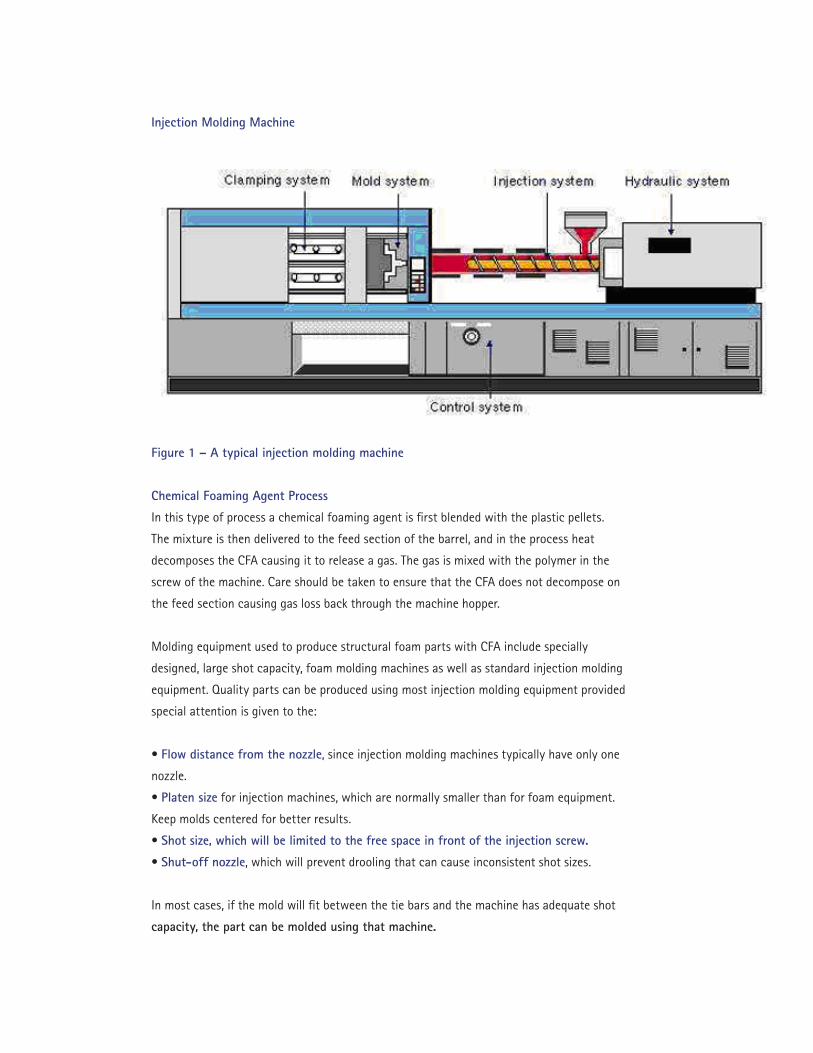
Injection Molding Machine
Figure 1 – A typical injection molding machine
Chemical Foaming Agent Process
In this type of process a chemical foaming agent is first blended with the plastic pellets.
The mixture is then delivered to the feed section of the barrel, and in the process heat
decomposes the CFA causing it to release a gas. The gas is mixed with the polymer in the
screw of the machine. Care should be taken to ensure that the CFA does not decompose on
the feed section causing gas loss back through the machine hopper.
Molding equipment used to produce structural foam parts with CFA include specially
designed, large shot capacity, foam molding machines as well as standard injection molding
equipment. Quality parts can be produced using most injection molding equipment provided
special attention is given to the:
• Flow distance from the nozzle, since injection molding machines typically have only one
nozzle.
• Platen size for injection machines, which are normally smaller than for foam equipment.
Keep molds centered for better results.
• Shot size, which will be limited to the free space in front of the injection screw.
• Shut-off nozzle, which will prevent drooling that can cause inconsistent shot sizes.
In most cases, if the mold will fit between the tie bars and the machine has adequate shot
capacity, the part can be molded using that machine.

Nozzle Design
The structural foam process requires control of the nozzle to minimize drooling and to
maintain a good flow rate. The best method of nozzle control is via a non-restrictive shut-off
nozzle. One that shuts off at the tip and is hydraulically or pneumatically operated usually
works best; those with an extended tip are still prone to drool.
If a shut-off nozzle is not available, drooling can be minimized by controlling the tip of the
nozzle. With at least two separate heat zones on the nozzle one can be used to maintain melt
temperature and the other to control the tip temperature. Reduce tip temperature to reduce
drooling without causing ‘freeze-off’. On structural foam machines, a thermally conductive
nozzle tip cap can be installed to insulate the hot nozzle from the cold mold, preventing the
mold from becoming a heat sink making temperature control more difficult.
Physical or Nitrogen Direct-Gassing Process
The physical or nitrogen process requires a specially designed, oversized platen, foam molding
machine in which nitrogen gas is introduced directly into the barrel of the extruder.
A screw containing one or more mixing sections blends the nitrogen gas with the hot polymer
melt. The mixture is fed into a large holding area called a melt accumulator and held under
pressure. Shot sizes of 45.36 kg (100 pounds) or more are not uncommon with this type of
equipment. When a predetermined shot is attained, the melt is forced through an external hot
manifold system to one or several hydraulically actuated shut-off nozzles. The number, size
and location of nozzles are determined by part configuration. Low pressure nitrogen presses
have lower injection pressure capabilities than standard injection machines. The platens
can be fitted with very large molds or several smaller ones. Nozzles can be independently
controlled to adjust timing and flow.
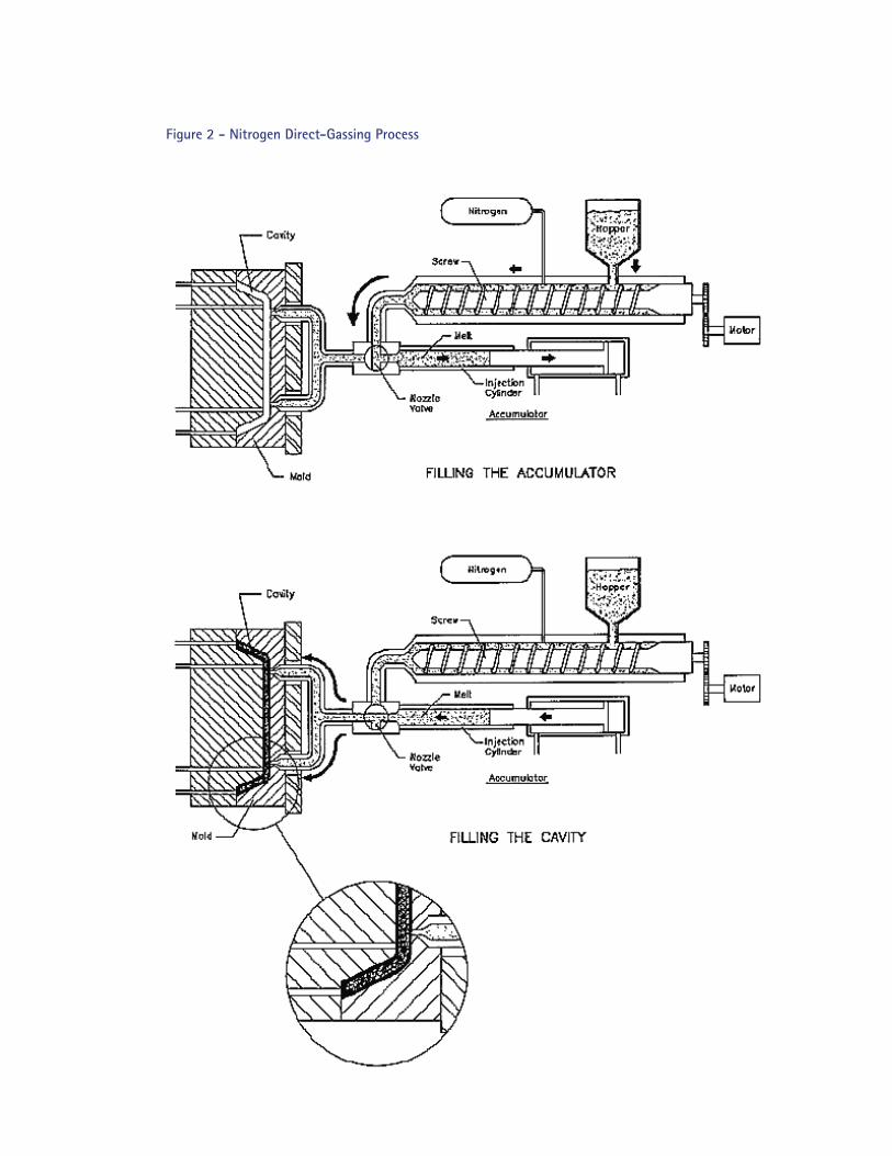
Figure 2 - Nitrogen Direct-Gassing Process

Gas Counter-pressure Process
In the gas counter-pressure method, inert gas in the molten polymer is contained by external
pressure until the entire shot is injected into the cavity. This prevents expansion during filling
of the mold and produces a molded part with a smooth skin. A sealed mold is used to control
the gas pressure during injection. It may also be necessary to seal ejector pins, the sprue
bushing and moving slides or cores to maintain a seal adequate to hold 3.45 to 34.45 bar
(50-500 psi) counter-pressure. The process should be considered as a tooling modification
rather than one that requires specialized molding equipment.
The general steps in the process are as follows:
• clamping the mold, pressurizing the cavity,
• injecting the polymer,
• depressurizing and ejecting the part.
This sequence has no significant effect on either cycle or cure time. Pressurization is
accomplished by connecting the mold to a supply of filtered, dry compressed air or, more
frequently, nitrogen. Solenoid-controlled valves regulate both gas intake and venting
to depressurize the cavity. The amount of gas is controlled by pressure transducers or
regulators.
Density reduction is normally less than that of a similar part molded with the low pressure
foam process. The exact amount of density will be determined by wall thickness, flow length,
part configuration and processing conditions.
The gas counter-pressure method does offer a number of advantages over other methods.
Because expansion of the polymer does not occur until the entire shot is injected, cell
structure is evenly distributed throughout the part, providing a more predictable, uniform
mechanical property profile and reducing the possibility of over-packed and over-stressed
sections that can result in poor dimensional control and warping.
Counter-pressure produces a much thicker and non-porous skin, sealing in the gases
that usually permeate the porous skin of conventional foam parts. This means that parts
usually can be painted directly from the mold without blistering. In addition, volatiles that
sometimes rise to the surface of parts are kept in solution, greatly reducing liquid build-up
in vent areas and on the parting line.
Machine Settings
To achieve optimum results when foaming, certain basic criteria must be maintained and
monitored. These include:
• Sufficient clamping force
• Proper melt and mold temperature
• Proper injection, holding, and back pressures
• Proper injection speed
Each application will require independent determination of optimum machine settings within
the ranges described for each material.
Clamping Force
Because SFM is a short shot process clamping force requirements for SFM are significantly
lower than those for conventional injection molding. Clamping force is the amount of
pressure required to keep the mold tightly closed during the injection of the molten polymer-
CFA mixture into the mold cavity. Mold cavity pressure is generated as the mold is filled
with polymer. Cavity pressure is affected by the projected surface area of the part, wall
thickness, and flow length and polymer viscosity. The clamping pressure must be higher than
the mold cavity pressure to keep the mold from opening and causing flash.
Melt Temperature
Melt temperature is that of the molten polymer prior to being injected into the mold
cavity. It is measured using a hand held pyrometer or other device. Do not rely on the set
temperatures to be accurate. The optimum melt temperature for any given part will depend
on several factors. Ideally, that temperature will ensure good flow characteristics, provide a
melt consistency that enables good cell structure formation, ensure good weld line strength
and produce a suitable surface finish.
Temperature Setting
The polymer is melted by feeding a solid polymer pellet to a heated screw and barrel. The
barrel is divided into several zones that are electrically heated by heater bands, and the
melt temperature is reached by adjusting the temperature of each zone. Molding machines
will have a feed zone below and slightly forward of the hopper, and a zone to control the
nozzle temperature. The number of zones between the feed and nozzle zone depends on the
molding equipment. The melt temperature should be reached by increasing or decreasing
the set temperatures at each zone and not by inducing shear heat generated by high back
pressure or very fast injection speeds.

The feed zone temperature should be set below the decomposition temperature of the CFA,
normally between 38 and 66°C (100 and 150°F) below the desired melt temperature. At
these temperatures the CFA does not release its gas too early allowing some of it to escape
via the machine throat and hopper.
With conventional injection machines, the temperatures are usually set so that the center
zone is the hottest. This should be set to allow the polymer and CFA to reach a high enough
temperature to provide proper decomposition and mixing. The front and nozzle zone can be
set lower initially and then adjusted for adequate flow and cycle time optimization. If the
machine is not fitted with a shut-off nozzle, the nozzle tip should be controlled separately to
control drooling.
With multi-nozzle structural foam machines, the temperature settings should be set at
the desired melt temperature throughout the screw, heat pipes, accumulator and manifold
areas. The various nozzles can be adjusted to help balance mold filling. With molds having
an internal hot manifold system, the machine barrel and nozzle should be set at the desired
melt temperature. The manifold and nozzle temperatures should be adjusted to control
drooling and to balance the material flow.
Cylinder Purging
Normal purging procedures using acrylic, polystyrene or high quality polyethylene can
typically be followed with the polymer to be molded. Because of the high molding
temperatures used with certain engineering polymers it is essential to purge thoroughly
before and after using these in machines that are to be used for other thermoplastics.
Failure to purge the machine thoroughly can result in delamination, black specks, weak
spots and degradation of the material. The appearance and performance of parts can also be
adversely affected.
Among the appropriate purging materials are scrap acrylic and crystal clear polystyrene.
High density polyethylene can also be used. Avoid low density polyethylene as it may break
down or degrade engineering polymers.
Flame retardant polymers must be purged completely as contamination can cause a
chemical reaction and degrade other polymers.
Mold Temperature
Mold temperature can influence surface finish, part release, polymer shrinkage, dimensions

and skin thickness.
The mold temperature is best determined by measuring at several locations of the mold
cavity and core with a hand held pyrometer or similar device. Variations in temperature
throughout the mold are not uncommon. In some cases it is desirable to have different
temperatures in certain regions of the mold. Temperatures should be measured before
molding begins and again after the process has reached a steady state.
The mold is initially heated with water or oil that is pumped through internal channels in the
mold. After the mold reaches the desired temperature, injection of the foam polymer can
begin. Subsequently, the mold temperature is maintained primarily by cooling since the melt
temperature of the polymer will heat the mold.
Warp Control
Mold temperature can be used to help control warp. The skin thickness on a structural foam
part can be slightly modified by increasing or decreasing the mold temperature. The outer
skin begins forming as soon as the molten polymer makes contact with the mold surface.
Cooler molds allow the skin to form and freeze quicker than a warmer or hot mold surface.
Relatively cool molds produce thin skins and hotter molds produce thicker skins. Typically,
heating the concave side of the molded part can help to reduce or eliminate the warping. A
4°C (40°F) temperature differential is usually sufficient and higher differentials may cause
galling or mold mismatch.
Part Shrinkage and Release
A mold temperature that is too cold can cause the part to shrink too fast and bind in the
mold. Deep ribs and bosses can become potential areas for hang ups. In some cases, cored
holes can become elongated because of this condition.
Pressure Settings
Pressure settings for both standard injection and structural foam molding machines are
described as Injection Pressure, Back Pressure and Holding Pressure. With structural foam
molding, the fill speed of the polymer into the mold cavity is determined by the polymer’s
resistance to flow and the pressure applied. Factors influencing this resistance are the type
of polymer, melt temperature, mold temperature, gate size and location, and part design.
Injection Pressure is the oil pressure in the injection cylinder, the flow rate of which will
determine the injection speed. In most cases pressure settings should be adjusted in order to

maintain a constant injection speed. Initial injection pressure should be set to about 3/4 of
the available pressure. On injection presses that have 1378.9 bar (20,000 psi) available; 827
to 1034.5 bar (12,000 to 15,000 psi) is usually sufficient.
Back Pressure will be determined by what type and how much CFA is being used. The
back pressure should be set high enough to prevent the screw or plunger from drifting i.e.
the screw or plunger continues to travel backwards after the selected shot size has been
plasticized. Insufficient back pressure will allow the polymer-CFA mix to foam. Increasing
the back pressure will eliminate any premature foaming and prevent the drift. Better shot to
shot consistency will usually be the result of better mixing of the polymer and CFA. In most
cases, back pressure settings will be 6.9 to 20.68 bar (100 to 300 psi).
Holding Pressure is not normally used in structural foam molding. Holding pressure is not
required because the part will be packed out by the expansion of the foam. Hold pressure
time may be used as a means of adding delay time to plastic extrusion, in which case a very
low pressure setting is all that is required.
Injection Speeds are faster with structural foam molding than with conventional injection
molding. The foaming occurs only after the polymer is injected into the mold cavity. The
speed in which the mold is filled can have an effect on several part characteristics:
• Part Weight – Slow fill speed may allow the flow front to cure and be more resistant
to flow. When this happens, the last material injected will tend to compress and become
denser. Injecting faster will help to control the density variation within the part.
• Flow Length – Faster injection speeds will increase flow lengths. The foaming polymer
will flow best when it is the hottest. Fast injection times can add shear heat to the polymer
which may overheat the material.
• Part Performance – Injection speed can be used to help ensure the mold is completely
filled with polymer, but too fast an injection speed may cause air entrapment or create a
back filling condition creating voids.
• Surface Appearance – Slow injection speeds can cause a rough surface at the end of flow.
Elephant skin, as it is often referred to, is a series of fold marks from semi-cured polymer.
Fast injection speed can cause small depressions or sink marks near the gate. These sink
marks are cause by an extreme increase in temperature via friction and shear.
Cooling Time
Cooling time is defined as the elapsed time between the end of injection and the opening
of the mold. Cooling or cure time is the amount of time required for the molten polymer
to solidify. Mold cooling for SFM is very important as tool temperature has a significant
effect on the overall surface finish, and can also be used to adjust the thickness of the skin.
Difficult to cool areas such as deep cores or thin blades may need special attention.
Several factors contribute to the required cooling time:
• Wall Thickness – The thickest area in the part determines the cure time. This area can be
the base of a rib or boss, a radius at a corner, a thick wall section or the base of the sprue. If
the cooling time is too short, the part will swell in the thick area. Post blow is the result of a
hot molten center surrounded by a semi-cured skin. The skin will not be able to contain the
pressure of the hot center and the part will continue to swell until the skin is cured.
• Chemical Foaming Agent (CFA) – Some blowing agents can help to reduce cooling times.
Endothermic CFAs absorb heat; exothermic CFA create heat.
• Part Geometry – Some applications need longer cooling times in order to control part
dimensions. Long cool times take advantage of the mold’s ability to act as a cooling fixture
for warpage control.
• Tool Design – The material used to construct the mold as well as the size, number and
location of the water channels can affect the overall cure time.
• Auxiliary Equipment – The size and condition of the mold temperature controllers or oil
heaters affect the heating and cooling efficiency. Inadequate water or oil flow may increase
cooling time.
Shot Size
The optimum shot size depends on several factors including target part weight, acceptable
surface finish and the elimination of sink marks. One method of optimizing the shot size is as
follows:
• First, fill the mold partially full, about 60%.
• Increase the shot size incrementally until the part just fills.
• Examine the part for surface quality.
• If the part appears to be rough at the extreme of flow, increase the weight until a
desirable surface is achieved.
• Check for sink marks.
• If sink is visible, reduce the shot size or increase the CFA amount; do not increase shot size.
Balancing Flow
Balanced filling produces parts with more uniform cell structure, optimal physical properties
and increased dimensional stability. Establishing the approximate fill pattern involves
producing several short shots incrementally, until the part is full. Ideally, the last area to fill
will be furthest from the polymer gate. In some instances, the last section to fill may be the
top of a thin rib or in a louvered area. Inspect each short shot taking note of how the flow
front advances. Be careful when it appears that the part is nearly full but it requires a great
deal more shot size to complete the filling, since this can cause ‘over-packing’ in locations
close to the gate. The foam structure is easier to compress than it is to push polymer into
a hard to fill area. Several methods of balancing polymer flow can be used to optimize the
filling process:
• Controlled Venting – The foaming process relies on a pressure drop to allow for
expansion. During the filling, the foaming melt travels towards vents. Locating the larger or
deeper vents in the harder to fill areas can help to guide the polymer in that direction. The
same procedure can be used to restrict the flow in easy to fill sections by reducing the size
of the vent.
• Flow Runners – Increasing the wall section in certain areas can feed more material to hard
to reach places. This procedure can be used strategically to get material to flow into thin
areas or to reduce flow lengths around openings. The part must be able to accommodate the
increase in wall section so as to not interfere with other components, but increasing the wall
thickness will also increase cooling time.
• Flow Restrictors – Decreasing the wall section in certain areas can help to slow polymer
filling in easy to fill places. The idea is to create a path of least resistance to the problem
areas by creating a diversion.
• Mold Temperature – Increasing the mold temperature in the areas last to fill will help to
keep the polymer from cooling thus enhancing the flow characteristics, but only a slight
increase in flow can be obtained.
• Injection Speed – Too fast an injection speed can cause air entrapment. The flow front
will contact the mold vents before all of the internal air escapes and will cause a short shot.
Slowing the injection speed should allow proper venting.
• Gate Location – Improper gate location may create a flow imbalance. Changing location
or adding additional gates can reduce flow lengths and help to balance the fill.
Mold Design
Molds for Structural Foam are constructed using similar techniques and guidelines to
conventional injection molding. Faster fill times and longer cycle times typically require
the use of larger gate and runner systems as well as strategic use of venting and cooling
methods. Structural foam molds are usually designed to withstand relatively low internal
pressures; between 250 to 1000 psi (17.2 to 68.9 bar) are normal ranges. These low mold
pressures allow for several options when choosing a construction material.

Vents
The importance of proper venting cannot be emphasized enough. Besides providing the
function of allowing internal air and blowing agent gases to exit the mold, a well designed
vent system will help to control the mold filling pattern. Generally, vents should be placed in
the obvious air entrapment locations, at the extremes of flow, knit line locations and hard to
fill areas.
The following guidelines are suggested when venting the mold:
• Machine relief slots on 3 in (76.2 mm) centers around the parting line, 0.50 to 0.75 in (12.7
to 19.0 mm) wide by 0.032 in (0.8 mm) deep.
• Machine vents 0.002 to 0.006 in (0.05 to 0.15 mm) deep at the extremes of flow and other
known air entrapment locations connecting the cavity to the relief slot.
• Progressively open vent depth to optimize part fill.
• Machine additional vents as required and connect to relief slots.
Injection speed can affect venting results. Adjustments in injection speeds should be made
at the same time vents are being modified. The clearance between the tool construction
material and ejector pins, moving cores and lifters can also be considered venting locations.
Ejector pins can provide a convenient means for venting deep pockets, bosses, ribs and
louvers.
Gates
Gates should not restrict flow thus affecting injection speed. Gates size and shape can
impact surface quality and density reduction. Gates also function as a means of balancing
flow to various parts of the mold. Engineering structural foam polymers can be molded using
common gate designs. The most frequently used is the direct sprue and edge gates. The
overall size of the gates is generally larger than with injection molding. Tunnel and pinpoint
gates have been used but only in small parts with short flow lengths. Beware of too large
a sprue for it may cause a longer cure time. Too short a cure may cause the sprue to break
away from the part during ejection. Sprue bushings having a 0.05 to 0.75 in (12.7 to 19.05
mm) taper per foot are typical. “O” dimensions of 0.200 in (5.08 mm) or more are generally
required to provide adequate flow.
Gates should be designed for uniform flow length and should favor flow into thin areas.
If possible, gate into a thin area and flow toward thicker sections. This should allow the
polymer to foam somewhat while in the thin section and to continue to expand once into
the thicker areas. The reverse approach would cause the foam in the thick sections to

compress while trying to force material into a thin section resulting in reduced density
reduction.
Gates should be located so as to not trap air and to move weld lines away from critical
impact and appearance areas. Also, gates should be located in areas which will allow for
easy de-gating and finishing.
Runners
Full round and trapezoidal runners are most common with structural foam molds. Generally
speaking, as long as the runner can supply the volume of polymer to the mold cavity without
reducing the injection time, any type runner will work. Full round runners usually begin in
size at 0.375 in (9.53 mm) diameter and depending on part weight and flow length can go
up to 0.75 in (19.1 mm) diameter. Beware of oversized runners. A large diameter runner can
increase cure time requirements.

Glossary of Terms
Air shot: To shoot or inject polymer into a puddle; done to inspect the molten material for
consistency, to measure melt temperature or as a means of purging.
Back pressure: The applied hydraulic pressure used to restrict the shot size formation;
applied to the back of a melt accumulator or reciprocating screw; used to control screw
drift, mixing and shot size adjustments.
Carrier: The pellet of polymer, wax or other mechanism used to compound the active
ingredient in manufacturing the chemical blowing agent.
Cavity pressure: The pressure generated in the mold cavity during the polymer injection
phase of the process.
CBA: Chemical blowing agent: A powder, liquid or pellet form blended with polymer at a
ratio to produce adequate foaming. The blowing agent decomposes during plastification
resulting in a release of an inert gas. The gas is mixed with molten polymer in the barrel and
is held under pressure until injection.
CFA: Chemical foaming agent: Another term for chemical blowing agent.
Clamp tonnage: The pressure required to keep the mold closed during polymer injection.
Cold slug: A hard piece of semi-cured polymer usually a result from a nozzle drool; a surface
imperfection close to the polymer gate often resembling a nail.
Contamination: To make impure via non-compatible substances. Examples are non-
compatible blowing agents or other polymers, degraded regrind, dirt, metal inserts and
painted regrind.
Controlled venting: Using mold vents to control mold filling. Vents cause pressure drops;
foam expands toward pressure drops.
Cure time: The amount of time required for the molten polymer to cure and solidify prior to
mold open and part ejection.

Decomposition temperature: The temperature in which a chemical foaming agent releases
gas. Most CFAs rely on time and temperature to fully decompose.
Degradation: A decline to a lower condition, quality or level, typically caused by over
heating via high temperature settings, shear, insufficient drying or chemical attack during
processing.
Delamination: The separation or peeling away of a thin layer of skin from the part surface;
caused by contamination or high heats.
Density reduction: Also referred to as weight reduction. The amount of weight savings when
a foamed part is compared to a solid injection molded part having the same design and wall
thickness.
Dew point: The temperature in which moisture is formed. A means of measuring the dryness
of process air used to dry polymer.
Drooling: Foamed polymer leaking from the machine nozzle. Pre-foamed polymer injected
into the mold can result in a surface imperfection.
Elephant skin: A rough surface condition caused by cold polymer folding over itself; usually
at the ends of flow.
Endothermic: A term that describes CFAs having heat absorbing characteristics. These
foaming agents tend to produce lower gas pressure, shorten cooling times, require less out-
gas time and have smoother surface finishes.
Exothermic: A term that describes CFAs having heat producing characteristics. These
foaming agents tend to produce higher gas pressure, and to have longer cycle times and
increased flow lengths.
Feed section: The section of the screw just under and slightly forward of the feed hopper.
Flash: Polymer that is forced out of the mold cavity area and onto the parting line or into
the vents of the mold; a very thin film of cured polymer attached to the molded part.
Flow: The ability of the molten polymer to move or travel during injection. Flow can be
influenced by temperature, part design, process conditions and tool design.
Flow leader: A small area in the mold which usually thickens the wall to allow material
to flow easier to select areas of the mold; used to get a few more inches of flow from the
material and usually not part of the mold design in the initial stage of tool construction.
Flow restrictor: A small area in the mold which usually thins the wall to stall the flow of
polymer to select areas of the mold; used to steer the material in another direction.
Gas counter-pressure: A surface enhancement process requiring a pressurized mold cavity;
a method of controlling the polymer flow, cell formation and exterior surface appearance.
Gate: The area of the mold where the polymer enters the mold cavity.
Hold pressure: The applied hydraulic injection pressure maintained after the completion of
mold filling; a secondary pressure.
Hopper: The device above the machine barrel used to store the polymer pellets.
Hot manifold: A heated polymer distribution system that attaches to the outside of the
stationary platen on a structural foam machine or is designed as part of the mold; an
extension of the hot melt system.
Hygroscopic: Having the ability to absorb moisture. Polymers that are hygroscopic require
drying before being processed.
Injection pressure: The applied hydraulic pressure used to push the polymer into the mold
cavity.
Injection Speed: The elapsed time required to fill the mold cavity.
Melt accumulator: Also referred to as a plunger; a large capacity holding area for molten
polymer; the area of a structural foam molding machine that determines the shot size.
Melt temperature: The actual temperature of the molten polymer injected into the mold
cavity. Melt temperature should be measured from a purge shot having the same residence
time as in the production process.
Mold temperature: The temperature of the mold before polymer injection.

Outgas: The release of gas from the core of the molded part. Outgas time is dependent on
skin thickness, type of polymer, type of blowing agent and processing conditions.
Over-packing: Injecting too much polymer into the mold; some sections of the mold can be
over packed; dense areas having little density reduction or cell structure, usually close to the
gate.
Physical process: A structural foam process that uses nitrogen or other gas as a physical
foaming agent.
Platen: The metal plates the mold is attached to on a plastic molding machine.
Post blow: The opposite of sink; the swelling or blistering on the part surface; found over
thick areas; caused by premature mold opening. The foam pressure in the hot molten center
of the thick area pushes the non-cured skin outward, and a void can often be seen under the
swelled area.
Projected surface area: The area the molded part projected onto a plane at right angle to
the direction of the mold; the area of the shadow the part can cast; used to calculate clamp
tonnage.
Purge: To clean the screw and barrel; to remove unwanted polymer from the barrel by intro-
ducing a new polymer to push out the old.
Regrind: Polymer that has been previously molded and ground into small pieces for repro-
cessing. Regrind is usually comprised of sprues, runners and unfilled parts.
Residence time: The amount of time the polymer is at process temperature prior to being
injected into the mold.
Runner: A means of distributing polymer from the sprue to one or more gates.
Screw: A rotating auger that uses a helical thread and a varying channel depth to convey,
melt, mix, and pump polymer; consists of a feed section, transition zone, metering section
and in some cases a mixing zone.
Short shot: The amount of polymer injected into a mold cavity at a volume less than that
required to fill the mold. A short shot of 90% of the mold cavity volume will produce a part
with a 10% weight reduction.
Shut-off nozzle: A device attached to the front of the molding machine barrel or hot
manifold system. It opens to allow polymer flow into the mold cavity and closes after
injection to help prevent drooling.
Sink: A depression on the part surface over a thick wall feature i.e., a rib, boss, thick sprue
gate or change in wall section. It is caused by the delayed cooling effects of the center of
the thick area; when the hot center cools, it shrinks and pulls down the skin on the surface.
Sprue: The transition point between the molding machine nozzle and the mold; a tapered
cylindrical shaped runner that feeds material from the machine to the mold cavity, runner
system or hot manifold.
Vent relief: The deep channel that connects the mold vent to the atmosphere.
Voids: A hollow section between the inner and outer skin caused by trapped gas or air.
Warp: To twist or deform from a desired shape often caused by molded in stress or
shrinkage.
Weight reduction: See density reduction.
Weld line: The point at which two flow fronts merge resulting in a visible line on the part
surface.

Contacting Endex International
Canada:
487 Westney Road South,
Unit #8
Ajax, Ontario L1S 6W8
Phone: 905.686.4335
Fax: 905.686.6691
USA:
1500 Dearborn Ave # 9
Aurora, IL 60505
Phone: 1800 Endex 50
Fax: 905.686.6691
UK:
9 Abbey Close
Alcester, B49 5QW
Phone: 01 789 765762
Fax: 01 789 765572
Note: To the best of our knowledge, the above information is correct. Since the way these products may be used is beyond our control, no responsibility is accepted by Endex International, Inc. for any loss or expense arising from their use. No liability is accepted if use of these products infringes any patent.
© Endex International, Inc. 2013.
Related Documents