Enclosed Switch SHL F-45 Limit Switches Enclosed Switch SHL Subminiature Enclosed Switch (Measuring 48 x 17.5 x 45 mm) with High Sealing Property • Built-in coil spring type basic switch housed in rigid zinc diecast alloy casting boasts long life and high precision. • Requires nearly the same operating force as conventional basic precision switches (2.35 to 3.92 N). • Molded terminal model is available. • Operation indicator model is also available. Model Number Structure ■ Model Number Legend Standard Models 1. Actuator D: Plunger Q: Panel mount plunger Q22: Panel mount roller plunger Q21: Panel mount crossroller plunger W: Short hinge lever W1: Hinge lever W2: Short hinge roller lever W21: Hinge roller lever W3: One-way action short hinge roller lever W31: One-way action hinge roller lever 2. Rated Current None: Standard 01: Micro Load Note: Refer to page 53 for Molded Terminal Models. Ordering Information ■ List of Models 2 1 SHL-@55-@ Actuator Standard model Micro voltage SHL-D55 SHL-D55-01 SHL-Q55 SHL-Q55-01 SHL-Q2255 SHL-Q2255-01 SHL-Q2155 SHL-Q2155-01 SHL-W55 SHL-W55-01 Plunger Panel mount plunger Panel mount roller plunger Panel mount crossroller plunger Short hinge lever

Welcome message from author
This document is posted to help you gain knowledge. Please leave a comment to let me know what you think about it! Share it to your friends and learn new things together.
Transcript

Enclosed Switch SHL F-45
Lim
it
Sw
itch
es
Enclosed Switch
SHLSubminiature Enclosed Switch (Measuring 48 x 17.5 x 45 mm) with High Sealing Property
• Built-in coil spring type basic switch housed in rigid zinc diecast alloy casting boasts long life and high precision.
• Requires nearly the same operating force as conventional basic precision switches (2.35 to 3.92 N).
• Molded terminal model is available.
• Operation indicator model is also available.
Model Number Structure
Model Number Legend
Standard Models
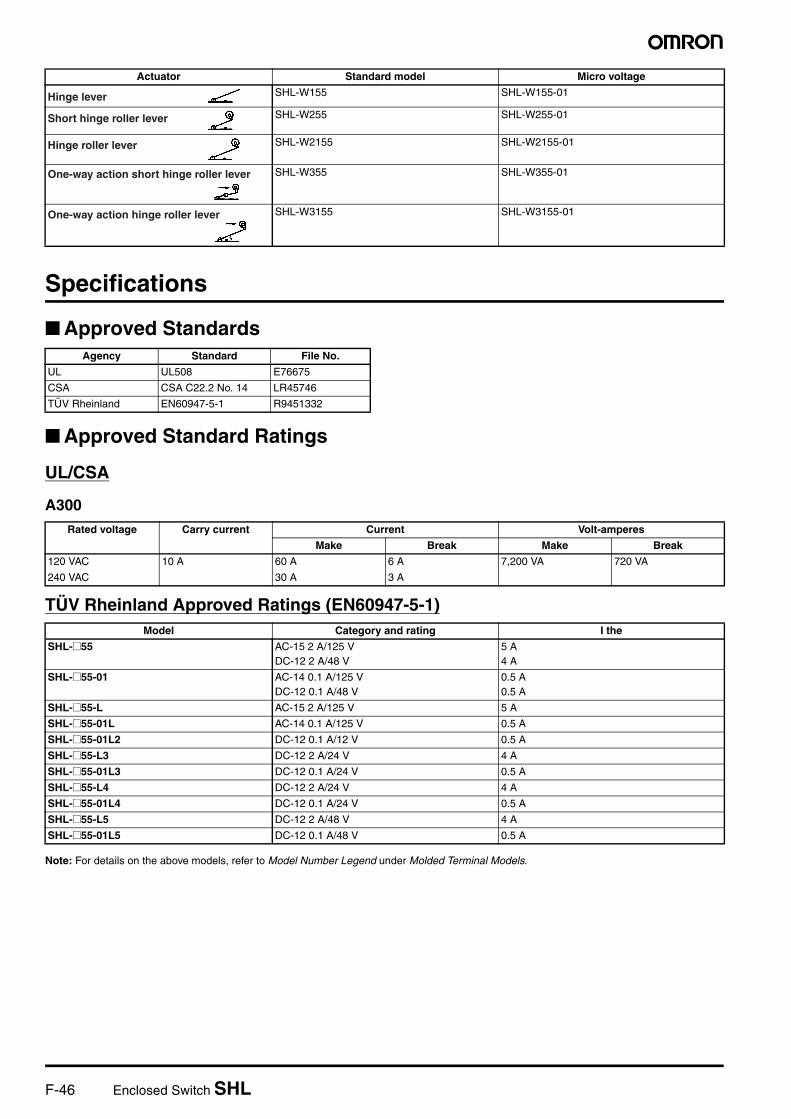
1. ActuatorD: PlungerQ: Panel mount plungerQ22: Panel mount roller plungerQ21: Panel mount crossroller plungerW: Short hinge leverW1: Hinge leverW2: Short hinge roller leverW21: Hinge roller leverW3: One-way action short hinge roller leverW31: One-way action hinge roller lever
2. Rated CurrentNone: Standard01: Micro Load
Note: Refer to page 53 for Molded Terminal Models.
Ordering Information
List of Models
21SHL-@55-@
Actuator Standard model Micro voltage
SHL-D55 SHL-D55-01
SHL-Q55 SHL-Q55-01
SHL-Q2255 SHL-Q2255-01
SHL-Q2155 SHL-Q2155-01
SHL-W55 SHL-W55-01
Plunger
Panel mount plunger
Panel mount roller plunger
Panel mount crossroller plunger
Short hinge lever
F-46 Enclosed Switch SHL
Specifications
Approved Standards
Approved Standard Ratings
UL/CSA
A300
TÜV Rheinland Approved Ratings (EN60947-5-1)
Note: For details on the above models, refer to Model Number Legend under Molded Terminal Models.
SHL-W155 SHL-W155-01
SHL-W255 SHL-W255-01
SHL-W2155 SHL-W2155-01
SHL-W355 SHL-W355-01
SHL-W3155 SHL-W3155-01
Actuator Standard model Micro voltage
Hinge lever
Short hinge roller lever
Hinge roller lever
One-way action short hinge roller lever
One-way action hinge roller lever
Agency Standard File No.
UL UL508 E76675
CSA CSA C22.2 No. 14 LR45746
TÜV Rheinland EN60947-5-1 R9451332
Rated voltage Carry current Current Volt-amperes
Make Break Make Break
120 VAC 10 A 60 A 6 A 7,200 VA 720 VA
240 VAC 30 A 3 A
Model Category and rating I the
SHL-@55 AC-15 2 A/125 VDC-12 2 A/48 V
5 A4 A
SHL-@55-01 AC-14 0.1 A/125 VDC-12 0.1 A/48 V
0.5 A0.5 A
SHL-@55-L AC-15 2 A/125 V 5 A
SHL-@55-01L AC-14 0.1 A/125 V 0.5 A
SHL-@55-01L2 DC-12 0.1 A/12 V 0.5 A
SHL-@55-L3 DC-12 2 A/24 V 4 A
SHL-@55-01L3 DC-12 0.1 A/24 V 0.5 A
SHL-@55-L4 DC-12 2 A/24 V 4 A
SHL-@55-01L4 DC-12 0.1 A/24 V 0.5 A
SHL-@55-L5 DC-12 2 A/48 V 4 A
SHL-@55-01L5 DC-12 0.1 A/48 V 0.5 A

Enclosed Switch SHL F-47
Lim
it
Sw
itch
es
Ratings
Note: 1. The above figures are for steady-state currents.2. Inductive loads have a power factor of 0.4 min. (AC) and a time constant of 7 ms max. (DC).3. Lamp load has an inrush current of 10 times the steady-state current.4. Motor load has an inrush current of 6 times the steady-state current.
Micro Voltage/Current Load Model
Rated voltage Non-inductive load Inductive load Inrush current
Resistive load Lamp load Inductive load Motor load
NC NO NC NO NC NO NC NO NC NO
125 VAC 10 A 1.5 A 3 A 2.5 A 15 A max.
250 VAC 10 A 1.5 A 2 A 1.5 A
480 VAC 2 A --- --- ---
8 VDC 10 A 2 A 5 A 2 A
14 VDC 10 A 2 A 5 A 2 A
30 VDC 5 A 1.5 A 1.5 A 1.5 A
125 VDC 0.4 A 0.4 A 0.05 A 0.05 A
250 VDC 0.2 A 0.2 A 0.03 A 0.03 A
Rated voltage Non-inductive load
Resistive load
NC NO
125 VAC 0.1 A
8 VDC 0.1 A
14 VDC 0.1 A
30 VDC 0.1 A
F-48 Enclosed Switch SHL
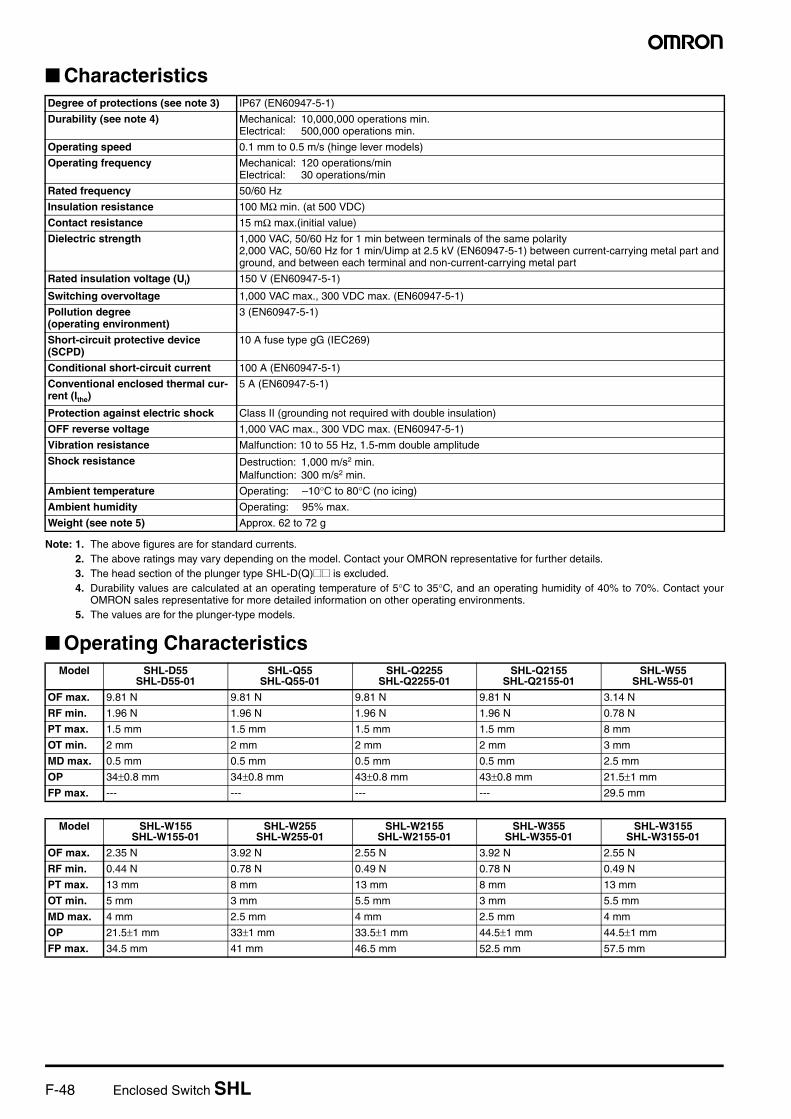
Characteristics
Note: 1. The above figures are for standard currents.2. The above ratings may vary depending on the model. Contact your OMRON representative for further details.3. The head section of the plunger type SHL-D(Q)@@ is excluded.4. Durability values are calculated at an operating temperature of 5°C to 35°C, and an operating humidity of 40% to 70%. Contact your
OMRON sales representative for more detailed information on other operating environments.5. The values are for the plunger-type models.
Operating Characteristics
Degree of protections (see note 3) IP67 (EN60947-5-1)
Durability (see note 4) Mechanical: 10,000,000 operations min.Electrical: 500,000 operations min.
Operating speed 0.1 mm to 0.5 m/s (hinge lever models)
Operating frequency Mechanical: 120 operations/minElectrical: 30 operations/min
Rated frequency 50/60 Hz
Insulation resistance 100 MΩ min. (at 500 VDC)
Contact resistance 15 mΩ max.(initial value)
Dielectric strength 1,000 VAC, 50/60 Hz for 1 min between terminals of the same polarity2,000 VAC, 50/60 Hz for 1 min/Uimp at 2.5 kV (EN60947-5-1) between current-carrying metal part and ground, and between each terminal and non-current-carrying metal part
Rated insulation voltage (Ui) 150 V (EN60947-5-1)
Switching overvoltage 1,000 VAC max., 300 VDC max. (EN60947-5-1)
Pollution degree (operating environment)
3 (EN60947-5-1)
Short-circuit protective device (SCPD)
10 A fuse type gG (IEC269)
Conditional short-circuit current 100 A (EN60947-5-1)
Conventional enclosed thermal cur-rent (Ithe)
5 A (EN60947-5-1)
Protection against electric shock Class II (grounding not required with double insulation)
OFF reverse voltage 1,000 VAC max., 300 VDC max. (EN60947-5-1)
Vibration resistance Malfunction: 10 to 55 Hz, 1.5-mm double amplitude
Shock resistance Destruction: 1,000 m/s2 min.Malfunction: 300 m/s2 min.
Ambient temperature Operating: –10°C to 80°C (no icing)
Ambient humidity Operating: 95% max.
Weight (see note 5) Approx. 62 to 72 g
Model SHL-D55SHL-D55-01
SHL-Q55SHL-Q55-01
SHL-Q2255SHL-Q2255-01
SHL-Q2155SHL-Q2155-01
SHL-W55SHL-W55-01
OF max. 9.81 N 9.81 N 9.81 N 9.81 N 3.14 N
RF min. 1.96 N 1.96 N 1.96 N 1.96 N 0.78 N
PT max. 1.5 mm 1.5 mm 1.5 mm 1.5 mm 8 mm
OT min. 2 mm 2 mm 2 mm 2 mm 3 mm
MD max. 0.5 mm 0.5 mm 0.5 mm 0.5 mm 2.5 mm
OP 34±0.8 mm 34±0.8 mm 43±0.8 mm 43±0.8 mm 21.5±1 mm
FP max. --- --- --- --- 29.5 mm
Model SHL-W155SHL-W155-01
SHL-W255SHL-W255-01
SHL-W2155SHL-W2155-01
SHL-W355SHL-W355-01
SHL-W3155SHL-W3155-01
OF max. 2.35 N 3.92 N 2.55 N 3.92 N 2.55 N
RF min. 0.44 N 0.78 N 0.49 N 0.78 N 0.49 N
PT max. 13 mm 8 mm 13 mm 8 mm 13 mm
OT min. 5 mm 3 mm 5.5 mm 3 mm 5.5 mm
MD max. 4 mm 2.5 mm 4 mm 2.5 mm 4 mm
OP 21.5±1 mm 33±1 mm 33.5±1 mm 44.5±1 mm 44.5±1 mm
FP max. 34.5 mm 41 mm 46.5 mm 52.5 mm 57.5 mm
Enclosed Switch SHL F-49
Lim
it
Sw
itch
es
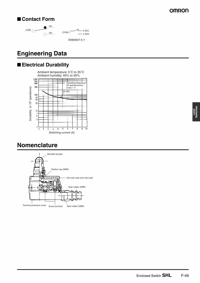
Contact Form
Engineering Data
Electrical Durability
Nomenclature
COM
NC
NO (COM) 12 (NC)
4 (NO)
EN60947-5-1
Ambient temperature: 5˚C to 35˚CAmbient humidity: 40% to 50%
Dur
abili
ty (
x 10
4 ope
ratio
ns)
Switching current (A)
Operating frequency: 30 operations/min. (cosφ = 1)
250 VAC
Movable plunger
Rubber cap (NBR)
Seal rubber (NBR)
Seal rubber (NBR)Screw terminalTerminal protection cover
Die-cast case (zinc die-cast)
F-50 Enclosed Switch SHL
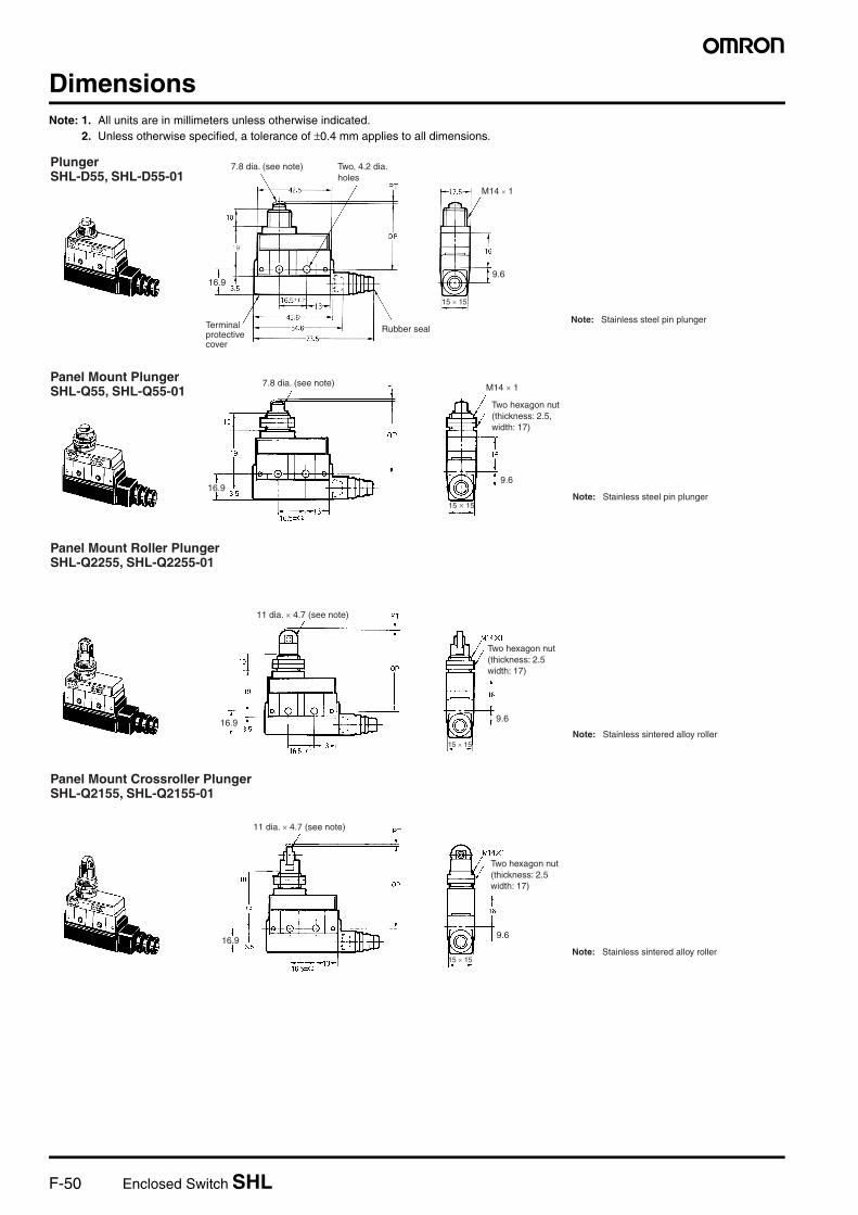
DimensionsNote: 1. All units are in millimeters unless otherwise indicated.
2. Unless otherwise specified, a tolerance of ±0.4 mm applies to all dimensions.
Plunger SHL-D55, SHL-D55-01
16.9
M14 × 1
9.6
15 × 15
7.8 dia. (see note) Two, 4.2 dia. holes
Terminal protective cover
Rubber sealNote: Stainless steel pin plunger
9.6
15 × 15
16.9
7.8 dia. (see note)
Note: Stainless steel pin plunger
Panel Mount Plunger SHL-Q55, SHL-Q55-01 M14 × 1
Two hexagon nut (thickness: 2.5, width: 17)
9.6
15 × 15
16.9
11 dia. × 4.7 (see note)
Note: Stainless sintered alloy roller
Panel Mount Roller Plunger SHL-Q2255, SHL-Q2255-01
Two hexagon nut (thickness: 2.5 width: 17)
16.99.6
15 × 15
11 dia. × 4.7 (see note)
Note: Stainless sintered alloy roller
Panel Mount Crossroller Plunger SHL-Q2155, SHL-Q2155-01
Two hexagon nut (thickness: 2.5 width: 17)

Enclosed Switch SHL F-51
Lim
it
Sw
itch
es
13
24
3.516.9
9.613
16
17.56.842.5
13
16.5
21 16
15 × 1516.5±0.2
Note: Stainless steel lever
Short Hinge Lever SHL-W55, SHL-W55-01 t = 1 (see note)
OPFP
35R
13
24
3.516.9
6.8
21 16
16.5±0.2
9.6
16
17.5
15 × 15
Hinge Lever SHL-W155, SHL-W155-01
Note: Stainless steel lever
t = 1 (see note)
53R
OPFP
13
24
3.516.99.6
16
6.8
21 16
15 × 1516.5±0.2
Note: Sintered stainless roller
Short Hinge Roller Lever SHL-W255, SHL-W255-01
OPFP
31R
9.5 dia. × 4.8 (see note)
13
24
3.516.9
9.6
16
6.8
21 16
15 × 1516.5±0.2
Note: Sintered stainless roller
Hinge Roller Lever SHL-W2155, SHL-W2155-01 9.5 dia. × 4.8 (see note)
OPFP
51R

F-52 Enclosed Switch SHL
13
24
3.516.9 9.6
16
6.8
21
15 × 1516.5±0.2
90°
16
Note: Stainless sintered roller
One-way Action Short Hinge Roller Lever SHL-W355, SHL-W355-01 9.5 dia. × 4.8 (see note)
OPFP
35.5ROperating direction
13
24
3.516.99.6
16
6.8
21 16
15 × 1516.5±0.2
90°
Note: Stainless sintered roller
One-way Action Hinge Roller Lever SHL-W3155, SHL-W3155-01
9.5 dia. × 4.8 (see note)
OPFP
52.5ROperating direction
Enclosed Switch SHL F-53
Lim
it
Sw
itch
es
Molded Terminal Models
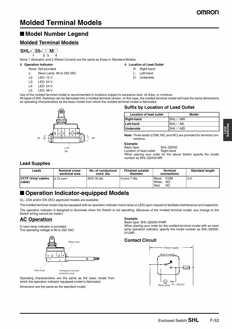
Model Number LegendMolded Terminal Models
Items 1 (Actuator) and 2 (Rated Current) are the same as those in Standard Models.
3. Operation IndicatorNone: Not providedL: Neon Lamp: 90 to 250 VACL2: LED: 12 VL3: LED: 24 VL4: LED: 24 VL5: LED: 48 V
4. Location of Lead OutletR: Right-handL: Left-handD: Underside
Use of the molded terminal model is recommended in locations subject to excessive dust, oil drips, or moisture.All types of SHL Switches can be fabricated into a molded terminal version. In this case, the molded terminal model will have the same dimensionsan operating characteristics as the basic model from which the molded terminal model is fabricated.
Suffix by Location of Lead Outlet
Note: Three leads (COM, NO, and NC) are provided for terminal con-nections.
Example:Basic type: SHL-Q2255Location of lead outlet: Right-handWhen placing your order for the above Switch specify the modelnumber as SHL-Q2255-MR
Lead Supplies
Operation Indicator-equipped ModelsUL, CSA and/or EN (IEC) approved models are available.
The molded terminal model may be equipped with an operation indicator (neon lamp or LED) upon request to facilitate maintenance and inspection.
The operation indicator is designed to illuminate when the Switch is not operating. (Because of the molded terminal model, any change to theSwitch wiring cannot be made.)
AC OperationA neon lamp indicator is provided.The operating voltage is 90 to 250 VAC.
Operating characteristics are the same as the basic model fromwhich the operation indicator equipped model is fabricated.
Dimension are the same as the standard model.
Example:Basic type: SHL-Q2255-01MRWhen placing your order for the molded terminal model with an neonlamp operation indicator, specify the model number as SHL-Q2255-01LMR.
Contact Circuit
1 2 3 4SHL-@55-@@M@
ML
MD
MR
Location of lead outlet Model
Right-hand SHL-@-MR
Left-hand SHL-@-ML
Underside SHL-@-MD
Leads Nominal cross-sectional area
No. of conductors/cond. dia.
Finished outside diameter
Terminal connections
Standard length
VCTF (Vinyl cabtire cable)
0.75 mm2 30/0.18 dia. 3-core 7 dia. Black: COMWhite: NORed: NC
3 m
Matte finish
Neon lamp Transparent terminal protection cover
Power supply
Built-in switch
Load
Neon lamp R = 240 kΩ
F-54 Enclosed Switch SHL
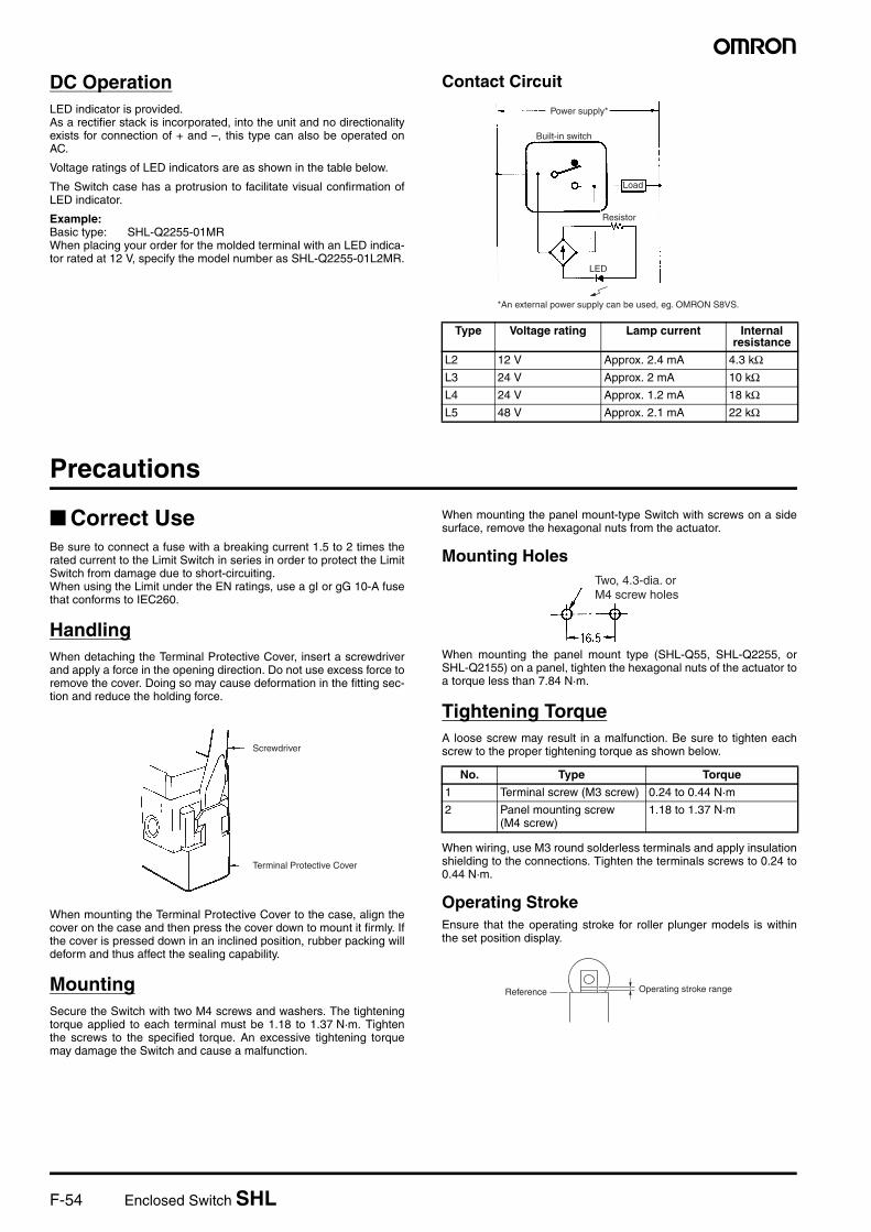
DC OperationLED indicator is provided.As a rectifier stack is incorporated, into the unit and no directionalityexists for connection of + and –, this type can also be operated onAC.
Voltage ratings of LED indicators are as shown in the table below.
The Switch case has a protrusion to facilitate visual confirmation ofLED indicator.
Example:Basic type: SHL-Q2255-01MRWhen placing your order for the molded terminal with an LED indica-tor rated at 12 V, specify the model number as SHL-Q2255-01L2MR.
Contact Circuit
Precautions
Correct UseBe sure to connect a fuse with a breaking current 1.5 to 2 times therated current to the Limit Switch in series in order to protect the LimitSwitch from damage due to short-circuiting.When using the Limit under the EN ratings, use a gI or gG 10-A fusethat conforms to IEC260.
HandlingWhen detaching the Terminal Protective Cover, insert a screwdriverand apply a force in the opening direction. Do not use excess force toremove the cover. Doing so may cause deformation in the fitting sec-tion and reduce the holding force.
When mounting the Terminal Protective Cover to the case, align thecover on the case and then press the cover down to mount it firmly. Ifthe cover is pressed down in an inclined position, rubber packing willdeform and thus affect the sealing capability.
MountingSecure the Switch with two M4 screws and washers. The tighteningtorque applied to each terminal must be 1.18 to 1.37 N·m. Tightenthe screws to the specified torque. An excessive tightening torquemay damage the Switch and cause a malfunction.
When mounting the panel mount-type Switch with screws on a sidesurface, remove the hexagonal nuts from the actuator.
Mounting Holes
When mounting the panel mount type (SHL-Q55, SHL-Q2255, orSHL-Q2155) on a panel, tighten the hexagonal nuts of the actuator toa torque less than 7.84 N·m.
Tightening TorqueA loose screw may result in a malfunction. Be sure to tighten eachscrew to the proper tightening torque as shown below.
When wiring, use M3 round solderless terminals and apply insulationshielding to the connections. Tighten the terminals screws to 0.24 to0.44 N·m.
Operating StrokeEnsure that the operating stroke for roller plunger models is withinthe set position display.
Type Voltage rating Lamp current Internal resistance
L2 12 V Approx. 2.4 mA 4.3 kΩL3 24 V Approx. 2 mA 10 kΩL4 24 V Approx. 1.2 mA 18 kΩL5 48 V Approx. 2.1 mA 22 kΩ
Power supply*
Built-in switch
Load
Resistor
LED
*An external power supply can be used, eg. OMRON S8VS.
Screwdriver
Terminal Protective Cover
No. Type Torque
1 Terminal screw (M3 screw) 0.24 to 0.44 N·m
2 Panel mounting screw (M4 screw)
1.18 to 1.37 N·m
Two, 4.3-dia. or M4 screw holes
Operating stroke rangeReference

Enclosed Switch SHL F-55
Lim
it
Sw
itch
es
Micro Load Applicable RangesWhen using a Limit Switch for opening or closing micro-load circuit(zones 1 through 3), contact failure may occur if a Limit Switch withordinary contact specifications is used. Therefore, when using LimitSwitches in the micro-load range, use ones with contact specifica-tions that are suited to each zone.
Use the SHL-@-01 micro-load models within the zones (1 through 3)shown in the following diagram.
The above diagram is for standard conditions (5°C to 35°C, 40% to70%). Since the values vary depending on the operating environ-ment conditions, contact your OMRON representative for furtherdetails.
OthersThe standard seal rubber for the lead wire outlet is one that allows 6-to 8-dia. cables. The appropriate nominal cross-section of the leadwire is 0.75 mm2. (When the sealing capability is required over a longperiod of time, use mold specifications.)
30
24
12
5
01 10 100 1,0000.1
1 mA
26 mA0.16 mA
800 mW5 mW
100 mA 160 mA
Current (mA)
Vol
tage
(V
DC
)
Operating range for micro-load models
Operating range for standard models
Unusable range

F-56 Enclosed Switch SHL
In the interest of product improvement, specifications are subject to change without notice.
ALL DIMENSIONS SHOWN ARE IN MILLIMETERS.
To convert millimeters into inches, multiply by 0.03937. To convert grams into ounces, multiply by 0.03527.
Cat. No. C026-E1-09
Related Documents