Encased girders prof. Ing. Ján Bujňák, Csc. Faculty of Civil Engineering ; University of Žilina

EncasGird
Jan 13, 2016
encased girders
Welcome message from author
This document is posted to help you gain knowledge. Please leave a comment to let me know what you think about it! Share it to your friends and learn new things together.
Transcript

Encased girders
prof. Ing. Ján Bujňák, Csc.
Faculty of Civil Engineering ; University of Žilina

1. Introduction
Originally developed only for railway bridges,
decks with encased beams have also been
widely and effectively used for road bridges.
The filler beam deck consists of the concrete
slab with stiff longitudinal reinforcement
made of rolled beams and transverse
reinforcement of steel bars. Closely spaced
steel beams and concrete act compositely
without specific mechanical shear
connection means.
The span covered by filler beam decks
range up to 40 meters for road bridges and
up to 30 meters for railway bridges. For
continuous structural system the maximum
spans are about 10 meters larger. Very
shallow depths of the bridge deck, quick
and easy erection without temporary
supports and falsework are the maine
advantageous features of this construction
system.

2. Design procedures assuming
unbonded system
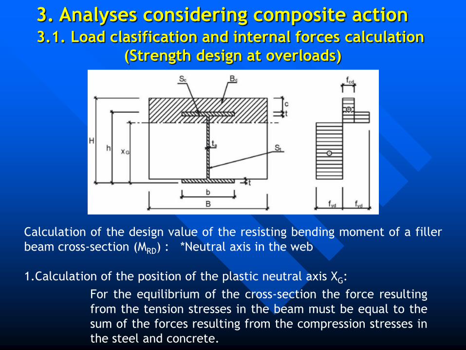
3. Analyses considering composite action3.1. Load clasification and internal forces calculation
(Strength design at overloads)
Calculation of the design value of the resisting bending moment of a filler
beam cross-section (MRD) : *Neutral axis in the web
1.Calculation of the position of the plastic neutral axis XG:
For the equilibrium of the cross-section the force resulting
from the tension stresses in the beam must be equal to the
sum of the forces resulting from the compression stresses in
the steel and concrete.

2.The resulting ultimate moment in the sum of the moments of these forces
related to XG:
3.Ultimate limit states:
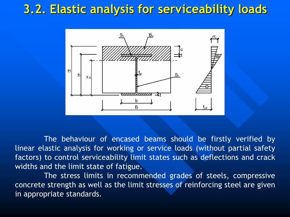
3.2. Elastic analysis for serviceability loads
The behaviour of encased beams should be firstly verified by
linear elastic analysis for working or service loads (without partial safety
factors) to control serviceability limit states such as deflections and crack
widths and the limit state of fatigue.
The stress limits in recommended grades of steels, compressive
concrete strength as well as the limit stresses of reinforcing steel are given
in appropriate standards.

4. More realistic analysis supported by
experimental study
Using the Cosmos finite element program, a more generalized
discredisation scheme that treats the bridge structure with encased beams
as a three-dimensional system can provide acceptable numerical results.
In the adopted computer model of the encased beam structure,
the concrete with tensile stresses greater than its strength is not assumed
to assist in resisting the moment. The steel carries all the tension in this
area. The neutral axis position is determined from the corresponding
interior forces distribution. In the next step, the stresses relevant to the
actual location of the neutral axis can be recalculated. Ultimate load is
limited by weakness in the tension steel or weakness in the compression
concrete.

To test the validity of the above computer model, the
experimental investigation was executed with the objectives to
comprehend the behaviour of slab bridge with encased beams at both the
service and ultimate load levels. Three models of composite beam
structure were fabricated. The 1,5 m long composite slab had a span 1,4 m
between the end supports, and consisted of two rolled-steel section I 120
and a concrete encasement. The concrete was 160 mm thick with a 28-day
concrete strength of 30 MPa. A mesh of smooth welded wire reinforced the
concrete. The models were instrumented for the purpose of measuring
deformation, strains across the depth of the encased steel beams, applied
load and slip between steel and concrete.

The presented method applied to a model, whose cross-section is
shown in previous page gives concentrated mid-span collapse load 95,4 kN,
greater than value 91,3 kN, provided by actual code analysis considering
composite action and the very underestimated load 61,2 kN declared by
the classic unbonded calculation. The limit load corresponding to the first
yield in experimental test was 150 kN. It was moreover found that the
encased beam models continued to carry loads long after the formation of
the first yield. Comparison of test deflections with calculated ones showed
similar behaviour. The calculated values are slightly greater.

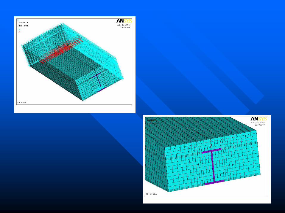
Ansys finite element program
Using the Ansys finite element program, a more
generalized discredisation scheme that treats the
bridge structure with encased beams
as a three-dimensional system can provide
acceptable numerical results.
The applied elements distribution
is illustrated at the next figure.
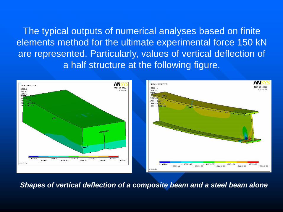
The typical outputs of numerical analyses based on finite
elements method for the ultimate experimental force 150 kN
are represented. Particularly, values of vertical deflection of
a half structure at the following figure.
Shapes of vertical deflection of a composite beam and a steel beam alone
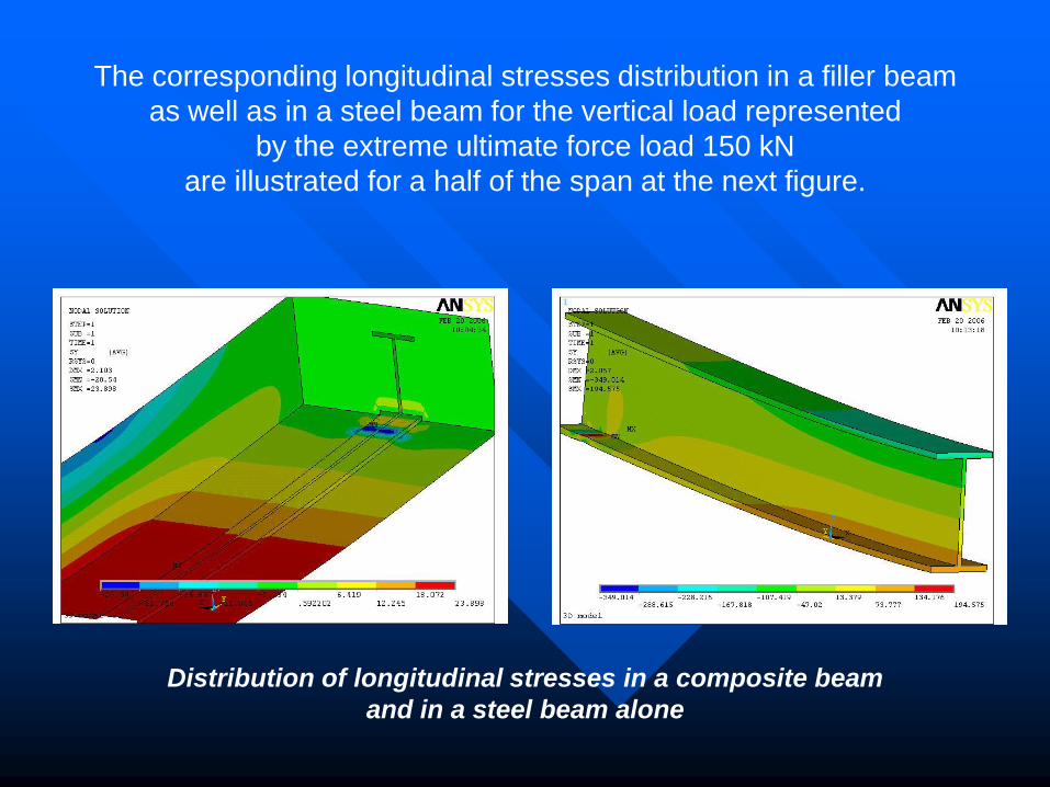
The corresponding longitudinal stresses distribution in a filler beam
as well as in a steel beam for the vertical load represented
by the extreme ultimate force load 150 kN
are illustrated for a half of the span at the next figure.
Distribution of longitudinal stresses in a composite beam
and in a steel beam alone
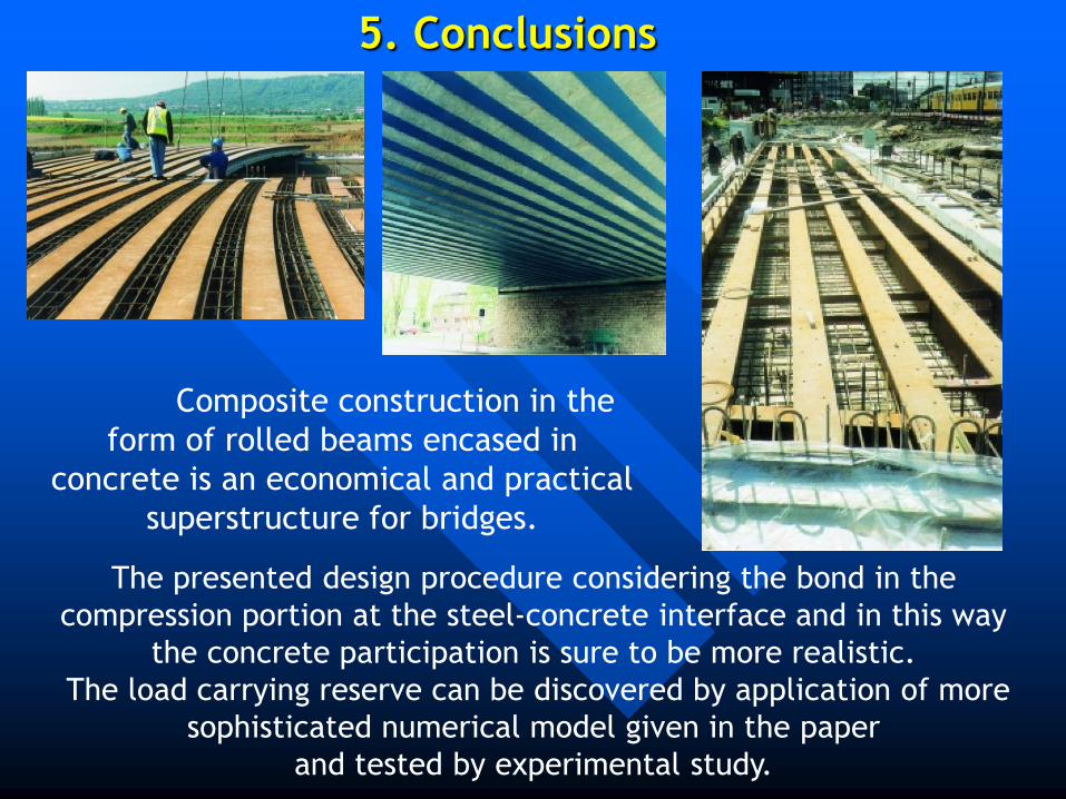
5. Conclusions
The presented design procedure considering the bond in the
compression portion at the steel-concrete interface and in this way
the concrete participation is sure to be more realistic.
The load carrying reserve can be discovered by application of more
sophisticated numerical model given in the paper
and tested by experimental study.
Composite construction in the
form of rolled beams encased in
concrete is an economical and practical
superstructure for bridges.

THANK YOU FOR
YOUR ATTENTION