DRAFT FOR DEVELOPMENT DD ENV 1317-4:2002 Road restraint systems — Part 4: Performance classes, impact test acceptance criteria and test methods for terminals and transitions of safety barriers ICS 13.200; 93.080.30 NO COPYING WITHOUT BSI PERMISSION EXCEPT AS PERMITTED BY COPYRIGHT LAW Licensed copy:Arup, 12/03/2010, Uncontrolled Copy, © BSI

Welcome message from author
This document is posted to help you gain knowledge. Please leave a comment to let me know what you think about it! Share it to your friends and learn new things together.
Transcript

Licensed copy:Arup, 12/03/2010, Uncontrolled Copy, © BSI
DRAFT FOR DEVELOPMENT
DD ENV 1317-4:2002Road restraint systems —
Part 4: Performance classes, impact test acceptance criteria and test methods for terminals and transitions of safety barriers
ICS 13.200; 93.080.30
NO COPYING WITHOUT BSI PERMISSION EXCEPT AS PERMITTED BY COPYRIGHT LAW

DD ENV 1317-4:2002
This Draft for Development, having been prepared under the direction of the Building and Civil Engineering Sector Policy and Strategy Committee, was published under the authority of the Standards Policy and Strategy Committee on 18 March 2002
© BSI 18 March 2002
ISBN 0 580 39245 7
National foreword
This Draft for Development is the official English language version of ENV 1317-4:2001.
This publication is not to be regarded as a British Standard.
It is being issued in the Draft for Development series of publications and is of a provisional nature. It should be applied on this provisional basis, so that information and experience of its practical application may be obtained.
Comments arising from the use of this Draft for Development are requested so that UK experience can be reported to the European organization responsible for its conversion into a European Standard. A review of this publication will be initiated 2 years after its publication by the European organization so that a decision can be taken on its status at the end of its three-year life. The commencement of the review period will be notified by an announcement in Update Standards.
According to the replies received by the end of the review period, the responsible BSI Committee will decide whether to support the conversion into a European Standard, to extend the life of the prestandard or to withdraw it. Comments should be sent in writing to the Secretary of BSI Subcommittee B/509/1, Road restraint systems, at 389 Chiswick High Road, London W4 4AL, giving the document reference and clause number and proposing, where possible, an appropriate revision of the text.
A list of organizations represented on this committee can be obtained on request to its secretary.
Cross-referencesThe British Standards which implement international or European publications referred to in this document may be found in the BSI Standards Catalogue under the section entitled “International Standards Correspondence Index”, or by using the “Find” facility of the BSI Standards Electronic Catalogue.
Summary of pages
This document comprises a front cover, an inside front cover, the ENV title page, pages 2 to 21 and a back cover.
The BSI copyright date displayed in this document indicates when the document was last issued.
Amendments issued since publication
Amd. No. Date Comments
Licensed copy:Arup, 12/03/2010, Uncontrolled Copy, © BSI

EUROPEAN PRESTANDARD
PRÉNORME EUROPÉENNE
EUROPÄISCHE VORNORM
ENV 1317-4
November 2001
ICS 13.200; 93.080.30
English version
Road restraint systems - Part 4: Performance classes, impacttest acceptance criteria and test methods for terminals and
transitions of safety barriers
Dispositifs de retenue routiers - Partie 4: Classes deperformance, critères d'acception des essais de choc etméthodes d'essai des extrémités et raccordements des
glissières de sécurité
Rückhaltesysteme an Straßen - Teil 4: Leistungsklassen,Abnahmekriterien für Anprallprüfungen und Prüfverfahren
für Anfangs-, End- und Übergangskonstruktionen vonSchutzeinrichtungen
This European Prestandard (ENV) was approved by CEN on 30 September 2001 as a prospective standard for provisional application.
The period of validity of this ENV is limited initially to three years. After two years the members of CEN will be requested to submit theircomments, particularly on the question whether the ENV can be converted into a European Standard.
CEN members are required to announce the existence of this ENV in the same way as for an EN and to make the ENV available promptlyat national level in an appropriate form. It is permissible to keep conflicting national standards in force (in parallel to the ENV) until the finaldecision about the possible conversion of the ENV into an EN is reached.
CEN members are the national standards bodies of Austria, Belgium, Czech Republic, Denmark, Finland, France, Germany, Greece,Iceland, Ireland, Italy, Luxembourg, Netherlands, Norway, Portugal, Spain, Sweden, Switzerland and United Kingdom.
EUROPEAN COMMITTEE FOR STANDARDIZATIONC OM ITÉ EUR OP ÉEN DE NOR M ALIS AT IONEUROPÄISCHES KOMITEE FÜR NORMUNG
Management Centre: rue de Stassart, 36 B-1050 Brussels
© 2001 CEN All rights of exploitation in any form and by any means reservedworldwide for CEN national Members.
Ref. No. ENV 1317-4:2001 E
Licensed copy:Arup, 12/03/2010, Uncontrolled Copy, © BSI

ENV 1317-4:2001 (E)
2
Contents
page
Foreword ............................................................................................................................................ 3
Introduction ........................................................................................................................................ 4
1 Scope........................................................................................................................................... 4
2 Normative references................................................................................................................... 4
3 Abbreviations ............................................................................................................................... 5
4 Terms and definitions................................................................................................................... 5
5 Terminals ..................................................................................................................................... 7
6 Transitions ................................................................................................................................. 14
7 Test methods ............................................................................................................................. 16
Bibliography...................................................................................................................................... 21
Licensed copy:Arup, 12/03/2010, Uncontrolled Copy, © BSI

ENV 1317-4:2001 (E)
3
Foreword
This European Prestandard has been prepared by Technical Committee CEN/TC 226 "Roadequipment", the secretariat of which is held by AFNOR.
This European Prestandard under the general title “Road restraint systems” consists of the followingParts:
- Part 1: Terminology and general criteria for test methods;
- Part 2: Performance classes, impact test acceptance criteria and test methods for safety barriers;
- Part 3: Performance classes, impact test acceptance criteria and test methods for crash cush-ions;
The following Parts are not yet available but in course of preparation :
- Part 4: Performance classes, impact test acceptance criteria and test methods for terminals andtransitions of safety barriers;
- Part 5: Product requirements, durability and evaluation of conformity;
- Part 6: Pedestrian restraint systems, pedestrian parapet.
According to the CEN/CENELEC Internal Regulations, the national standards organizations of thefollowing countries are bound to announce this European Prestandard: Austria, Belgium, CzechRepublic, Denmark, Finland, France, Germany, Greece, Iceland, Ireland, Italy, Luxembourg, Nether-lands, Norway, Portugal, Spain, Sweden, Switzerland and the United Kingdom.
Licensed copy:Arup, 12/03/2010, Uncontrolled Copy, © BSI

ENV 1317-4:2001 (E)
4
Introduction
The design purpose of safety barriers installed on roads is to contain or to contain and redirect errantvehicles that either leave the carriage way or are likely to encroach into the path of oncomingvehicles. EN 1317-2 deals with the impact performance of a safety barrier. However, difficulties arisein providing adequate safe terminations to the barrier. Consequently, terminals, which are defined asthe beginning and/or end treatment of a safety barrier, are required to have specified impactperformances. A terminal provides a smooth transition from no containment to the containment of thebarrier, without introducing additional hazard for head on impacts.
Problems may also arise in the connection between two different safety barriers having consistentdifference in stiffness. Transitions may be needed, that are required to have specified impactperformances.
The objective of this prestandard is to lead to the harmonization of current National Regulations, tocategorize them into performance classes and help develop new systems and improve existingsystems.
This Part of the prestandard defines the classes of performance required of terminals and transitionsfor the restraint.
The impact severity of vehicles in collision with terminals and transitions is rated by the indicesacceleration severity index (ASI), theoretical head impact velocity (THIV) and post-impact headdeceleration (PHD).
Attention is drawn to the fact that the acceptance of a terminal or transition will require the successfulcompletion of a series of tests (see Tables 1 to 8).
To ensure proper use of this Part of this series, it is essential to consider all the other relevantdocuments within the series. Additionally, the quality of manufacture, durability, satisfactory roadsideinstallation and ease of maintenance are important safety criteria.
1 Scope
This European Prestandard specifies requirements for the performance of terminals and transitions.It defines performance classes and acceptance criteria for impact tests.
2 Normative references
This European Prestandard incorporates by dated or undated reference, provisions from otherpublications. These normative references are cited at the appropriate places in the text, and thepublications are listed hereafter. For dated references, subsequent amendments to or revisions ofany of these publications apply to this European Prestandard only when incorporated in it byamendments or revisions. For undated references the latest edition of the publication referred toapplies (including amendments).
EN 1317-1:1998, Road restraint systems - Part 1: Terminology and general technical criteria for testmethods.
Licensed copy:Arup, 12/03/2010, Uncontrolled Copy, © BSI

ENV 1317-4:2001 (E)
5
EN 1317-2, Road Restraint Systems - Part 2: Performance classes, impact test acceptance criteriaand test methods for safety barriers.
ISO 6487, Road vehicles - Measurement techniques in impact tests - Instrumentation.
ISO 10392, Road vehicles with two axles - Determination of centre of gravity.
3 Abbreviations
ASI Acceleration severity index;THIV Theoretical head impact velocity;PHD Post-impact head deceleration;VCDI Vehicle cockpit deformation index;U Terminal on upstream position;D Terminal on downstream position;A Terminal on upstream as well as downstream position;L Length of terminal or transition.
Impact speed classes abbreviations are:80 80 km/h100 100 km/h110 110 km/h
Test vehicle mass codes are:1 900 kg2 1300 kg3 1500 kg
4 Terms and definitions
4.1terminaltreatment of the beginning and/or the end of a safety barrier
NOTE In addition it can provide an anchorage for the barrier system. The length L of a terminal is thelongitudinal distance from the nose to the end of the terminal, i.e. to the beginning of the barrier. The length of aterminal is shown diagrammatically in Figure 1 for two alternative shapes.
Licensed copy:Arup, 12/03/2010, Uncontrolled Copy, © BSI

ENV 1317-4:2001 (E)
6
Key
A BarrierB Terminal3 Side view4 Plan view – a)5 Plan view – b)
Figure 1 – Length of a Terminal with two alternative shapes (a and b)
4.2system type tested terminalmultiple performance product that can be assembled to form different models from the same set ofcomponents, to obtain different performances, with the same working mechanism for the system andfor its components
4.3transitionso that interface between two safety barriers of different cross section or different lateral stiffness, thecontainment is continuous
NOTE 1 The purpose of transitions is to provide a gradual change from the first to the second barrier, toprevent the hazards of an abrupt variation. A transition is designed to connect two specified barriers. The
Licensed copy:Arup, 12/03/2010, Uncontrolled Copy, © BSI

ENV 1317-4:2001 (E)
7
length of a transition is the distance between the ends of the two barriers connected by the transition, as shownschematically in Figure 2.
Key
A Barrier BB TransitionC Barrier A
Figure 2 – Length of a Transition
NOTE 2 The junction between two barriers having the same cross-section and the same material, anddiffering in the working width no more than one class, is not be considered a transition.
4.4removable barrier sectionpart of barrier which allow for quick removal and reinstallation for emergency reasons provision maybe required for barrier sections to be temporarily opened, but yet having containment performances
NOTE If such a barrier has a length not exceeding 40 m, it is be considered to be a special transition.
5 Terminals
5.1 Performance classes
Terminals shall be tested in accordance with Table 1. The length of the terminal shall conform to thedesign specification and be installed together with sufficient length of safety barrier so as todemonstrate the performance of the terminal.
A successfully tested installation at a given performance class, shall normally be considered ashaving met conditions of lower classes.
NOTE The acceptance tests required for each terminal performance class are reported in Table 1. These areclassified according to an increasing containment capacity.
Licensed copy:Arup, 12/03/2010, Uncontrolled Copy, © BSI
ENV 1317-4:2001 (E)
8
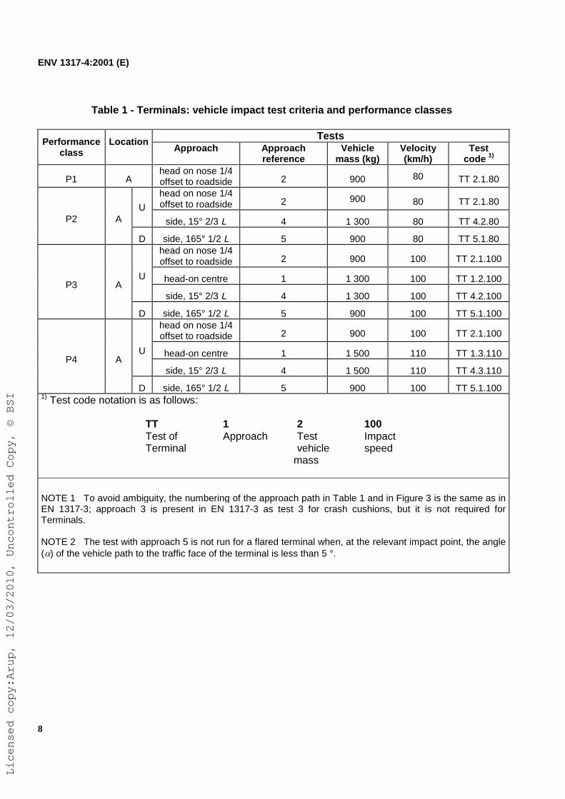
Table 1 - Terminals: vehicle impact test criteria and performance classes
TestsPerformanceclass
LocationApproach Approach
referenceVehicle
mass (kg)Velocity(km/h)
Testcode 1)
P1 Ahead on nose 1/4offset to roadside 2 900 80 TT 2.1.80
head on nose 1/4offset to roadside 2 900 80 TT 2.1.80
U
side, 15° 2/3 L 4 1 300 80 TT 4.2.80P2 A
D side, 165° 1/2 L 5 900 80 TT 5.1.80head on nose 1/4offset to roadside 2 900 100 TT 2.1.100
head-on centre 1 1 300 100 TT 1.2.100U
side, 15° 2/3 L 4 1 300 100 TT 4.2.100P3 A
D side, 165° 1/2 L 5 900 100 TT 5.1.100head on nose 1/4offset to roadside 2 900 100 TT 2.1.100
head-on centre 1 1 500 110 TT 1.3.110U
side, 15° 2/3 L 4 1 500 110 TT 4.3.110P4 A
D side, 165° 1/2 L 5 900 100 TT 5.1.1001) Test code notation is as follows:
TT 1 2 100Test of Approach Test ImpactTerminal vehicle speed
mass
NOTE 1 To avoid ambiguity, the numbering of the approach path in Table 1 and in Figure 3 is the same as inEN 1317-3; approach 3 is present in EN 1317-3 as test 3 for crash cushions, but it is not required forTerminals.
NOTE 2 The test with approach 5 is not run for a flared terminal when, at the relevant impact point, the angle(�) of the vehicle path to the traffic face of the terminal is less than 5 °.
Licensed copy:Arup, 12/03/2010, Uncontrolled Copy, © BSI

ENV 1317-4:2001 (E)
9
a)
b)
Key
� Approach 1� Approach 2� Approach 4� Approach 51 Barrier2 Terminal3 1/2 vehicle width4 1/4 vehicle width
Figure 3 – Vehicle approach paths with two alternative shapes of Terminal (a and b)
Licensed copy:Arup, 12/03/2010, Uncontrolled Copy, © BSI

ENV 1317-4:2001 (E)
10
5.2 Tests for system type tested terminals
A group of models covering a range of performance classes can be derived from a single ParentTerminal, once the latter has been successfully tested to this prestandard.
Provided that the models in the group:
a) are assembled from the same set of components;b) have the same product name;c) have the same working mechanism for the system and for the components,
the group, specified by the drawings of all the models, may be tested as a single product withmultiple performance possibilities. If the tests specified by the group test matrix are passed, theterminal shall be accepted as a multiple performance product, i.e. each model is accepted in therelevant performance class.
If the parent Terminal belongs to the highest performance class the test matrix shall be the oneshown in Table 2 or 3, depending on the highest performance class of the group.
Table 2 – Parent Terminal P4
Performance class Tests
P4 All tests
P3 TT 1.2.100
P2 TT 2.1.80
Table 3 – Parent terminal P3 (shape a)
Performance class Tests
P3 All tests
P2 TT 2.1.80
If the parent terminal belongs to the performance class P3 and the group covers also the class P4the test matrix shall be in accordance with Table 4.
Table 4 – Parent terminal P3 (shape b)
Performance Class Tests
P4 TT 2.1.100TT 1.3.110
P3 All tests
P2 TT 2.1.80
Licensed copy:Arup, 12/03/2010, Uncontrolled Copy, © BSI
ENV 1317-4:2001 (E)
11
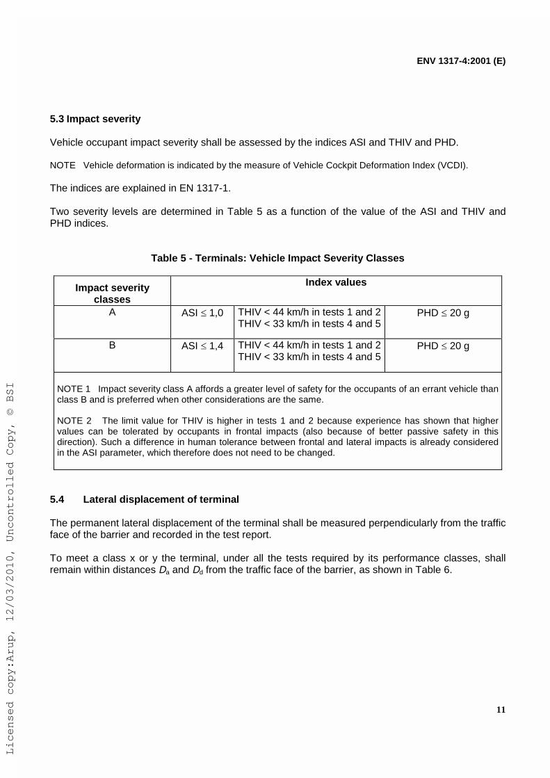
5.3 Impact severity
Vehicle occupant impact severity shall be assessed by the indices ASI and THIV and PHD.
NOTE Vehicle deformation is indicated by the measure of Vehicle Cockpit Deformation Index (VCDI).
The indices are explained in EN 1317-1.
Two severity levels are determined in Table 5 as a function of the value of the ASI and THIV andPHD indices.
Table 5 - Terminals: Vehicle Impact Severity Classes
Impact severityclasses
Index values
A ASI � 1,0 THIV < 44 km/h in tests 1 and 2THIV < 33 km/h in tests 4 and 5
PHD � 20 g
B ASI � 1,4 THIV < 44 km/h in tests 1 and 2THIV < 33 km/h in tests 4 and 5
PHD � 20 g
NOTE 1 Impact severity class A affords a greater level of safety for the occupants of an errant vehicle thanclass B and is preferred when other considerations are the same.
NOTE 2 The limit value for THIV is higher in tests 1 and 2 because experience has shown that highervalues can be tolerated by occupants in frontal impacts (also because of better passive safety in thisdirection). Such a difference in human tolerance between frontal and lateral impacts is already consideredin the ASI parameter, which therefore does not need to be changed.
5.4 Lateral displacement of terminal
The permanent lateral displacement of the terminal shall be measured perpendicularly from the trafficface of the barrier and recorded in the test report.
To meet a class x or y the terminal, under all the tests required by its performance classes, shallremain within distances Da and Dd from the traffic face of the barrier, as shown in Table 6.
Licensed copy:Arup, 12/03/2010, Uncontrolled Copy, © BSI

ENV 1317-4:2001 (E)
12
Table 6 – Permanent lateral displacement zones for terminals
Class code Displacement (m)
1 0,52 1,5x3
Da
3,01 1,02 2,03 3,5
y
4
Dd
>3,5
The distances Da and Dd are shown by lines Aa and Ad in Figure 4.
Key
1 Departure side2 Approach side3 Traffic face of barrierA BarrierB Terminal
Figure 4 – Terminal permanent displacement zones
5.5 Impact test acceptance criteria
5.5.1 General
For completion of a successful test the following impact acceptance criteria and measurement shallapply.
Licensed copy:Arup, 12/03/2010, Uncontrolled Copy, © BSI

ENV 1317-4:2001 (E)
13
5.5.2 Terminal behaviour
Elements of the terminal shall not penetrate the passenger compartment of the vehicle. Deformationsof, or intrusions into, the passenger compartment that could cause serious injuries are not permitted.
No major part of the Terminal shall become totally detached and come to rest outside the permanentlateral displacement zones defined in 5.4.
Anchorages and fixings shall perform to the terminal design specifications and other specifiedrequirements as listed in the test report.
5.5.3 Test vehicle behaviour
The vehicle shall not overturn, although rolling, yawing and moderate pitching may be accepted.For the performance class P1 rolling onto a side may be accepted.
The exit box is defined by:- the rebound line F, perpendicular to the barrier traffic face, 6 m ahead of the nose of the
Terminal;- the two side lines A and D parallel to the barrier traffic face, at distances Za and Zd; the line R,
perpendicular to the barrier traffic face at the end of the Terminal, defines the end of lines Aand D.
Key
1 Departure side2 Approach side3 Traffic face of barrier4 End of terminal5 Rebound lineA BarrierB Terminal
Figure 5 – Exit box
Licensed copy:Arup, 12/03/2010, Uncontrolled Copy, © BSI

ENV 1317-4:2001 (E)
14
For different tests the vehicle post-impact trajectory shall be restricted by the following criteria:
a) in the tests with approaches 1 and 2 no vehicle wheel track shall cross the lines of the exitbox specified in Table 7 unless the velocity of the vehicle centre of mass is less than 10 % ofthe prescribed impact speed;
b) in the tests with approaches 4 and 5 no vehicle wheel track shall cross the lines of the exitbox specified in Table 7;
c) in the test with approach 4 the vehicle shall remain on the approach side.
Table 7 – Exit box
Approach Exit box control lines
1, 2 F, A, D
4, 5 A
The classes of terminals Z1, Z2, Z3 and Z4 shall be ranked according to the distances Za and Zd givenin Table 8 and shown in Figure 5.
Table 8 – Exit box dimensions Za and Zd
Classes of Z Approach Side Za (m) Departure Side Zd (m)
Z1 4 4
Z2 6 6
Z3 4 no limit
Z4 6 no limit
5.5.4 Severity Index
ASI, THIV and PHD shall be computed using at least the minimum amount of vehicle instrumentationas specified in 7.6. These values shall be quoted in the test report (see EN 1317-1:1998, clause 7).
The maximum values of ASI, THIV and PHD shall not exceed the values given in Table 5.
For a series of tests on a particular terminal, all resulting impact severity values shall be recorded inthe test report, and the highest value shall determine the impact severity class.
6 Transitions
6.1 Performances classes
For transitions, the definitions and the classification of containment classes, acceptance tests,working width, dynamic deflection, severity index as well as acceptance criteria and test methods,shall be those specified in EN 1317-2.
Licensed copy:Arup, 12/03/2010, Uncontrolled Copy, © BSI

ENV 1317-4:2001 (E)
15
With the exception of 6.2, the containment class of a transition shall not be lower than the lower norhigher than the higher containment class of the two connected barriers; its working width shall not belarger than the larger working width of the two connected barriers.
6.2 Removable barrier sections
A removable barrier section not longer than 40 m shall be tested as a single transition.
A removable barrier section longer than 40 m shall be considered a different barrier, connected to thenormal barrier by two transitions.
-The barrier shall have passed the two tests specified in EN1317-2 relative to its class. Thetransition shall be tested as specified in clause 7.
If the removable barrier section is longer then 40 m but shorter than 70 m, the barriers shall be tested inthe removable barrier section configuration, i.e. with the two transitions installed, and the impact point shall be1/3 of the removable barrier section length.In this case test TB11 (see EN 1317-2) on this impact pointmay be omitted. The transition shall be tested as specified in clause 7.
The containment class of a removable barrier section may be lower than the containment class of thebarrier, and the working width one class higher.
6.3 Critical impact requirements
6.3.1 General
For acceptance each transition shall pass two tests, as specified in EN 1317-2, one with a lightvehicle for impact severity and another with a heavy vehicle for maximum containment.
The direction of impact as well as the impact point shall be chosen as the most critical for each test.
6.3.2 Critical impact direction
As the most critical direction of impact is from the softer to the stiffer barrier, then the impact directionshall be from the lower containment barrier toward the higher containment barrier, provided the latterhas demonstrated the smaller dynamic deflection in the high containment test.
If the dynamic deflection of the higher containment barrier is higher than the dynamic deflection of thelower containment barrier the impact direction for each test shall be chosen by the test laboratory,and the justification for such choices shall be recorded in the test report.
If the two connected barriers have the same containment class, the impact direction shall be from thehigher dynamic deflection to the lower.
6.3.3 Critical impact point
In general the impact point for the light vehicle shall be at a distance of 3/4 of the length L of thetransition from the beginning of the transition, in the direction of impact.
The impact for the heavy vehicle point shall be the midpoint of the transition.
In special cases different choices of the critical impact point may be made by the test laboratory, and
Licensed copy:Arup, 12/03/2010, Uncontrolled Copy, © BSI

ENV 1317-4:2001 (E)
16
shall be recorded with justification in the test report.
6.4 Impact test acceptance criteria
The impact test acceptance criteria for transitions are specified in EN 1317-2.
7 Test methods
7.1 Test site
The test area shall be generally flat with a gradient not exceeding 2,5 %. It shall have a levelhardened paved surface and shall be clear of standing water, ice or snow at the time of the test. Itshall be of sufficient size to enable the test vehicle to be accelerated up to the required speed andcontrolled so that its approach to the safety barrier is stable.
To enable the vehicle exit characteristics to be evaluated, the paved area shall exceed 40 m in lengthbeyond the expected break point and 15 m in front of the safety barrier line of vehicle contact with thesafety barrier.
Appropriate measures shall be taken in order to minimize dust generation from the test area and thetest vehicle during the impact test so that photographic records will not be obscured.
Appropriate measures shall be taken to ensure that in the exit area the test vehicle does not collidewith any independent obstruction which could cause additional deformation of the test vehiclethereby precluding the accurate measurement of the vehicle cockpit deformation index (VCDI) (seeEN 1317-1:1998, annex A).
7.2 Test vehicle
7.2.1 General
The vehicles to be used in the tests shall be production models representative of the current traffic,having characteristics and dimensions within the vehicle specifications defined in EN 1317-1:1998,clause 5.
The tyres shall be inflated to the manufacturer’s recommended pressures. The condition of thevehicle shall be such as to satisfy the requirements for the issue of a certificate of road worthiness inrespect of tyres, suspension, wheel alignment and bodywork. No repairs or modifications shall bemade that would alter the general characteristics of the vehicle. The vehicle shall be clean and mudor deposits which may cause dust on impact shall be removed prior to testing.
The vehicle shall not be restrained by the control of the steering or any other means during impactand whilst the vehicle is in the exit box as defined in Figure 5 (e.g. braking, antilock brakes, blockingor fixing).
7.2.2 Loading Conditions
All ballast weights shall be securely fixed to the vehicle in such a way as not to exceed themanufacturer’s specifications for distribution of weight in the horizontal and vertical planes.
Licensed copy:Arup, 12/03/2010, Uncontrolled Copy, © BSI

ENV 1317-4:2001 (E)
17
NOTE All fluids are included in the total inertial test mass.
7.3 The terminal and transition
7.3.1 General
Detailed descriptions and design specifications of the terminal/transition shall be included in the testreport (see EN 1317-1:1998, clause 9), to enable verification of conformity, of the installed system tobe tested, with the design specification.
7.3.2 Installation
The terminal and transition shall conform to the structural design details and with the systeminstallation details as given in the design specification of the manufacturer.
7.3.3 Position of the impact point
The appropriate approach and impact point for the tests shall be in accordance with Figure 3 forterminals, and in 6.3 and 6.4 for transitions.
7.4 Procedures for recording test data
The following test characteristics shall be recorded.
a) Pre-test data:
- Mass of the vehicle and location of the centre of gravity of the vehicle in the test conditionincluding added ballast (see ISO 10392).
- Interior and exterior photographs of the vehicle.
- Photographs of the position and construction of the terminal/transition.
NOTE It is recommended that the mass vehicle moments of inertia should be reported.
b) Test data:
- Vehicle speed at impact;- Vehicle approach path;- Vehicle rebound speed;- Linear accelerations and angular velocities;- Permanent deflection of the terminal/transition system;- Vehicle rebound path;- Dynamic deflection and/or working width of the terminal/transition as far as recommended,
corrected to the nearest decimal point;- Photographic records from high speed cine film cameras and/or high speed video cameras
deployed in such a way to give a complete record of the vehicle response and terminal/transitionbehaviour, including deformation and deflections.
Licensed copy:Arup, 12/03/2010, Uncontrolled Copy, © BSI

ENV 1317-4:2001 (E)
18
c) Post-test data:
- General damage and deformation of the test vehicle and that information which is necessary forthe computation of VCDI (see EN 1317-1:1998, annex A).
- Damage to the terminal/transition.
- Still photographs to aid reporting.
7.5 Accuracies and tolerances of impact speeds and angles
7.5.1 Vehicle impact speed
Vehicle impact speed shall be measured along the vehicle approach path no further than 6 m beforethe impact point. The overall accuracy of speed measurement shall be within � 1,0 %.
Impact speed shall be within a tolerance of 0,7+0
%.
7.5.2 Vehicle approach angle
Vehicle approach angle shall be measured along the vehicle approach path no further than 6 mbefore the impact point by a suitable method. The overall accuracy shall be within � 0,5°.
Impact angle shall be within a tolerance of 1,5 1 -
� °.
For approach 5 (see Figure 3) the actual impact angle is 180° - 165° = 15°. Then the acceptablelimits of the approach angle are
�
��
���
�
���
5,163
166
5,1
1165
7.5.3 Vehicle exit speed
Vehicle exit speed shall be measured with an accuracy of � 5 km/h.
7.5.4 Combined tolerances of speed and angle
To avoid large differences of impact energy, the maximum tolerance for speed and angle shall not becombined. At the upper angle tolerance of + 1,5° the upper speed tolerance shall be reduced to+ 5 %, and at the angle tolerance of –1,0° the lower speed tolerance is increased to + 2 %.
NOTE The complete combined tolerance envelope is shown in Figure 6.
The given tolerances only serve to take account of different test installations or test procedures andare not intended to provide a spectrum from which the energy of the test may be chosen. In anycase, the nominal values of Table 1 shall be taken.
Licensed copy:Arup, 12/03/2010, Uncontrolled Copy, © BSI

ENV 1317-4:2001 (E)
19
Key
1 Angle [°]2 Speed [%]
Figure 6 – Envelope of combined tolerances
7.5.5 Vehicle impact point
The lateral displacement of the vehicle approach path shall be measured with an accuracy of� 0,05 m by a suitable method. The permitted tolerance for the lateral displacement of the vehiclepath from its true direction shall be less than � 0,15 m at the moment of contact.
7.6 Vehicle instrumentation
The minimum vehicle instrumentation for recording linear accelerations and angular velocities,consists of a set of three linear acceleration transducers, mutually orthogonal, aligned with thevehicle axis (longitudinal, transversal and vertical), plus one angular rate transducer to record yawrate.
The three accelerometers and the yaw rate sensor should be mounted on a common block andplaced as close to the vehicle centre of gravity as practical. If this cannot be achieved, referenceshould be made to EN 1317-1:1998, clause 6.
Acceleration and angular velocity transducers and the relevant recording channels shall conform toISO 6487, the frequency class being CFC 180.
NOTE CFC 60 should be used for plotting graphical results.
Licensed copy:Arup, 12/03/2010, Uncontrolled Copy, © BSI

ENV 1317-4:2001 (E)
20
7.7 Photographic coverage
Photographic coverage shall be sufficient to describe clearly terminal/transition and vehicle motionduring and after impact.
High speed cameras and/or high speed video cameras shall be operated at a minimum of 200frames per second.
High speed cameras and one normal speed camera shall be located to record the performance of theterminal/transition. For the recommended camera schedule see Figure 7.
Key
1 Barrier2 Terminal
a) One high speed camera looking normal to the terminal/transition centre line.
b) One or two overhead high speed cameras, located in a way to cover the vehicle motion fromat least 6 m before the impact point to a distance to record the performance of theterminal/transition.
c) One panned camera at normal speed sited at right angles to the path of the vehicle.
d) (Optional) One high speed camera looking from a position behind the impact point in order torecord the vehicle roll, vertical lift, penetration and sequence of action as theterminal/transition is struck.
Figure 7 - Layout of cameras for recording tests
7.8 Test report
The test report shall conform to EN 1317-1:1998, clause 9.
Licensed copy:Arup, 12/03/2010, Uncontrolled Copy, © BSI

ENV 1317-4:2001 (E)
21
Bibliography
EN 1317-3, Road Restraint Systems - Part 3: Performance classes, impact test acceptance criteriaand test methods for crash cushions.
Licensed copy:Arup, 12/03/2010, Uncontrolled Copy, © BSI

Licensed copy:Arup, 12/03/2010, Uncontrolled Copy, © BSI
DD ENV 1317-4:2002
BSI
389 Chiswick High Road
London
W4 4AL
BSI — British Standards InstitutionBSI is the independent national body responsible for preparing British Standards. It presents the UK view on standards in Europe and at the international level. It is incorporated by Royal Charter.
Revisions
British Standards are updated by amendment or revision. Users of British Standards should make sure that they possess the latest amendments or editions.
It is the constant aim of BSI to improve the quality of our products and services. We would be grateful if anyone finding an inaccuracy or ambiguity while using this British Standard would inform the Secretary of the technical committee responsible, the identity of which can be found on the inside front cover. Tel: +44 (0)20 8996 9000. Fax: +44 (0)20 8996 7400.
BSI offers members an individual updating service called PLUS which ensures that subscribers automatically receive the latest editions of standards.
Buying standards
Orders for all BSI, international and foreign standards publications should be addressed to Customer Services. Tel: +44 (0)20 8996 9001. Fax: +44 (0)20 8996 7001. Email: [email protected]. Standards are also available from the BSI website at http://www.bsi-global.com.
In response to orders for international standards, it is BSI policy to supply the BSI implementation of those that have been published as British Standards, unless otherwise requested.
Information on standards
BSI provides a wide range of information on national, European and international standards through its Library and its Technical Help to Exporters Service. Various BSI electronic information services are also available which give details on all its products and services. Contact the Information Centre. Tel: +44 (0)20 8996 7111. Fax: +44 (0)20 8996 7048. Email: [email protected].
Subscribing members of BSI are kept up to date with standards developments and receive substantial discounts on the purchase price of standards. For details of these and other benefits contact Membership Administration. Tel: +44 (0)20 8996 7002. Fax: +44 (0)20 8996 7001. Email: [email protected].
Information regarding online access to British Standards via British Standards Online can be found at http://www.bsi-global.com/bsonline.
Further information about BSI is available on the BSI website at http://www.bsi-global.com.
Copyright
Copyright subsists in all BSI publications. BSI also holds the copyright, in the UK, of the publications of the international standardization bodies. Except as permitted under the Copyright, Designs and Patents Act 1988 no extract may be reproduced, stored in a retrieval system or transmitted in any form or by any means – electronic, photocopying, recording or otherwise – without prior written permission from BSI.
This does not preclude the free use, in the course of implementing the standard, of necessary details such as symbols, and size, type or grade designations. If these details are to be used for any other purpose than implementation then the prior written permission of BSI must be obtained.
Details and advice can be obtained from the Copyright & Licensing Manager. Tel: +44 (0)20 8996 7070. Fax: +44 (0)20 8996 7553. Email: [email protected].
Related Documents