EN 301 358 V1.1.1 (1999-04) European Standard (Telecommunications series) Satellite Earth Stations and Systems (SES); Satellite User Terminals (SUT) using satellites in geostationary orbit operating in the 19,7 GHz to 20,2 GHz (space-to-earth) and 29,5 GHz to 30 GHz (earth-to-space) frequency bands

Welcome message from author
This document is posted to help you gain knowledge. Please leave a comment to let me know what you think about it! Share it to your friends and learn new things together.
Transcript

EN 301 358 V1.1.1 (1999-04)European Standard (Telecommunications series)
Satellite Earth Stations and Systems (SES);Satellite User Terminals (SUT) using satellites in geostationary
orbit operating in the 19,7 GHz to 20,2 GHz (space-to-earth)and 29,5 GHz to 30 GHz (earth-to-space) frequency bands
ETSI
EN 301 358 V1.1.1 (1999-04)2
ReferenceDEN/SES-00027 (cko00ico.PDF)
Keywordssatellite, earth station, FSS, regulation
ETSI
Postal addressF-06921 Sophia Antipolis Cedex - FRANCE
Office address650 Route des Lucioles - Sophia Antipolis
Valbonne - FRANCETel.: +33 4 92 94 42 00 Fax: +33 4 93 65 47 16
Siret N° 348 623 562 00017 - NAF 742 CAssociation à but non lucratif enregistrée à laSous-Préfecture de Grasse (06) N° 7803/88
Individual copies of this ETSI deliverablecan be downloaded from
http://www.etsi.orgIf you find errors in the present document, send your
comment to: [email protected]
Copyright Notification
No part may be reproduced except as authorized by written permission.The copyright and the foregoing restriction extend to reproduction in all media.
© European Telecommunications Standards Institute 1999.All rights reserved.
ETSI
EN 301 358 V1.1.1 (1999-04)3
Contents
Intellectual Property Rights ............................................................................................................................... 6
Foreword ............................................................................................................................................................ 6
Introduction........................................................................................................................................................ 6
1 Scope........................................................................................................................................................ 7
2 References ............................................................................................................................................... 8
3 Definitions and abbreviations.................................................................................................................. 83.1 Definitions ......................................................................................................................................................... 83.2 Abbreviations................................................................................................................................................... 10
4 Radio Frequency (RF) ........................................................................................................................... 104.1 Off-axis spurious radiation............................................................................................................................... 104.1.1 Purpose....................................................................................................................................................... 104.1.2 Specification............................................................................................................................................... 104.1.3 Conformance tests ...................................................................................................................................... 114.2 On-axis spurious radiation ............................................................................................................................... 114.2.1 Purpose....................................................................................................................................................... 114.2.2 Specification............................................................................................................................................... 124.2.2.1 "Carrier-on" state.................................................................................................................................. 124.2.2.2 "Carrier-off" and "Transmission disabled" state................................................................................... 124.2.3 Conformance tests ...................................................................................................................................... 124.3 Off-axis EIRP emission density within the band.............................................................................................. 124.3.1 Purpose....................................................................................................................................................... 124.3.2 Specification............................................................................................................................................... 124.3.3 Conformance tests ...................................................................................................................................... 134.4 Transmit polarization discrimination (linear) or voltage axial ratio (circular)................................................. 134.4.1 Purpose....................................................................................................................................................... 134.4.2 Specification............................................................................................................................................... 134.4.2.1 Specification 1...................................................................................................................................... 134.4.2.2 Specification 2...................................................................................................................................... 134.4.3 Conformance test........................................................................................................................................ 134.5 Antenna transmit gain pattern (co-polar and cross-polar) ................................................................................ 144.5.1 Purpose....................................................................................................................................................... 144.5.2 Specification............................................................................................................................................... 144.5.3 Conformance tests ...................................................................................................................................... 144.6 Carrier suppression .......................................................................................................................................... 144.6.1 Purpose....................................................................................................................................................... 144.6.2 Specification............................................................................................................................................... 144.6.3 Conformance tests ...................................................................................................................................... 144.7 Antenna pointing accuracy............................................................................................................................... 144.7.1 Purpose....................................................................................................................................................... 144.7.2 Specification............................................................................................................................................... 144.7.3 Conformance tests ...................................................................................................................................... 15
5 Control and Monitoring Functions (CMF) ............................................................................................ 155.1 Processor monitoring ....................................................................................................................................... 165.1.1 Purpose....................................................................................................................................................... 165.1.2 Specification............................................................................................................................................... 165.1.3 Conformance tests ...................................................................................................................................... 175.2 Transmit subsystem monitoring ....................................................................................................................... 175.2.1 Purpose....................................................................................................................................................... 175.2.2 Specification............................................................................................................................................... 175.2.3 Conformance tests ...................................................................................................................................... 175.3 Power-on/Reset................................................................................................................................................ 175.3.1 Purpose....................................................................................................................................................... 17
ETSI
EN 301 358 V1.1.1 (1999-04)4
5.3.2 Specification............................................................................................................................................... 175.3.3 Conformance tests ...................................................................................................................................... 175.4 Control Channel (CC) reception ...................................................................................................................... 185.4.1 Purpose....................................................................................................................................................... 185.4.2 Specification............................................................................................................................................... 185.4.3 Conformance tests ...................................................................................................................................... 185.5 Network control commands ............................................................................................................................. 185.5.1 Purpose....................................................................................................................................................... 185.5.2 Specification............................................................................................................................................... 185.5.3 Conformance test........................................................................................................................................ 185.6 Initial burst transmission.................................................................................................................................. 195.6.1 Purpose....................................................................................................................................................... 195.6.2 Specification............................................................................................................................................... 195.6.3 Conformance tests ...................................................................................................................................... 19
6 Test method ........................................................................................................................................... 196.1 Off-axis spurious radiation............................................................................................................................... 206.1.1 Test method................................................................................................................................................ 206.1.1.1 Up to 1 000 MHz.................................................................................................................................. 206.1.1.1.1 Test site........................................................................................................................................... 206.1.1.1.2 Measuring receivers ........................................................................................................................ 216.1.1.1.3 Procedure ........................................................................................................................................ 216.1.1.2 Above 1 000 MHz ................................................................................................................................ 216.1.1.2.1 Identification of the significant frequencies of spurious radiation .................................................. 216.1.1.2.1.1 Test site ..................................................................................................................................... 216.1.1.2.1.2 Procedure .................................................................................................................................. 226.1.1.2.2 Measurement of radiated power levels of identified spurious radiation.......................................... 226.1.1.2.2.1 Test site ..................................................................................................................................... 226.1.1.2.2.2 Procedure .................................................................................................................................. 226.1.1.2.3 Measurement of conducted spurious radiation at the antenna flange .............................................. 246.1.1.2.3.1 Test site ..................................................................................................................................... 246.1.1.2.3.2 Procedure .................................................................................................................................. 246.2 On-axis spurious radiation ............................................................................................................................... 246.2.1 Test method................................................................................................................................................ 246.2.1.1 Test site ................................................................................................................................................ 246.2.1.2 Method of measurement ....................................................................................................................... 246.2.1.2.1 General............................................................................................................................................ 246.2.1.2.2 Method of measurement at the antenna flange................................................................................ 256.2.1.2.3 Method of measurement for an EUT with antenna .........................................................................256.3 Off-axis EIRP emission density within the band.............................................................................................. 266.3.1 Test method................................................................................................................................................ 266.3.1.1 Transmit output power density ............................................................................................................. 266.3.1.1.1 Test site........................................................................................................................................... 266.3.1.1.2 Method of measurement.................................................................................................................. 276.3.1.2 Antenna transmit gain........................................................................................................................... 276.3.1.2.1 General............................................................................................................................................ 276.3.1.2.2 Test site........................................................................................................................................... 276.3.1.2.3 Method of measurement.................................................................................................................. 286.3.1.3 Antenna transmit radiation patterns ...................................................................................................... 296.3.1.3.1 General............................................................................................................................................ 296.3.1.3.2 Test site........................................................................................................................................... 296.3.1.3.3 Test arrangement............................................................................................................................. 296.3.1.3.4 Co-polar radiation pattern - azimuth ............................................................................................... 296.3.1.3.5 Co-polar radiation pattern - elevation ............................................................................................. 306.3.1.3.6 Cross-polar radiation pattern - azimuth........................................................................................... 306.3.1.3.7 Cross-polar radiation pattern - elevation......................................................................................... 316.3.2 Computation of results ............................................................................................................................... 316.4 Transmit polarization discrimination ............................................................................................................... 326.4.1 General....................................................................................................................................................... 326.4.2 Test site ...................................................................................................................................................... 326.4.2.1 Method of measurement ....................................................................................................................... 32
ETSI
EN 301 358 V1.1.1 (1999-04)5
6.5 Carrier suppression - Test method .................................................................................................................. 336.6 Antenna pointing for SUTs - Test method....................................................................................................... 346.7 SUT Control and Monitoring Functions (CMF) .............................................................................................. 346.7.1 Test arrangement........................................................................................................................................ 346.7.2 Processor monitoring - Test method........................................................................................................... 356.7.3 Transmit subsystem monitoring - Test method .......................................................................................... 356.7.4 Power-on/Reset - Test method ................................................................................................................... 366.7.5 Control Channel (CC) reception - Test method.......................................................................................... 366.7.6 Network control commands - Test method ................................................................................................ 376.7.7 Initial burst transmission - Test method ..................................................................................................... 39
Annex A (informative): Pointing stability methodology .................................................................... 40
Bibliography .................................................................................................................................................... 41
History.............................................................................................................................................................. 42

ETSI
EN 301 358 V1.1.1 (1999-04)6
Intellectual Property RightsIPRs essential or potentially essential to the present document may have been declared to ETSI. The informationpertaining to these essential IPRs, if any, is publicly available for ETSI members and non-members, and can be foundin SR 000 314: "Intellectual Property Rights (IPRs); Essential, or potentially Essential, IPRs notified to ETSI in respectof ETSI standards", which is available free of charge from the ETSI Secretariat. Latest updates are available on theETSI Web server (http://www.etsi.org/ipr).
Pursuant to the ETSI IPR Policy, no investigation, including IPR searches, has been carried out by ETSI. No guaranteecan be given as to the existence of other IPRs not referenced in SR 000 314 (or the updates on the ETSI Web server)which are, or may be, or may become, essential to the present document.
ForewordThis European Standard (Telecommunications series) has been produced by ETSI Technical Committee Satellite EarthStations and Systems (SES).
National transposition dates
Date of adoption of this EN: 26 March 1999
Date of latest announcement of this EN (doa): 30 June 1999
Date of latest publication of new National Standardor endorsement of this EN (dop/e): 31 December 1999
Date of withdrawal of any conflicting National Standard (dow): 31 December 1999
IntroductionThe present document applies to Satellite User Terminals (SUT) either for individual or collective use.
The present document deals with the specification defined to protect other users of the frequency spectrum, both satelliteand terrestrial, from unacceptable interference.
The requirements have been selected to ensure an adequate level of compatibility with other radio services. The levels,however, do not cover extreme cases which may occur in any location but with a low probability of occurrence.
The present document may not cover those cases where a potential source of interference which is producingindividually repeated transient phenomena or a continuous phenomena is present, e.g. a radar or broadcast site in thenear vicinity. In such a case it may be necessary to use special protection applied to the source of interference, or theinterfered part or both.
The present document does not contain any requirement, recommendation or information about the installation of theSUTs.

ETSI
EN 301 358 V1.1.1 (1999-04)7
1 ScopeThe present document defines the minimum specifications of the technical characteristics of Satellite User Terminals(SUT) operating as part of a satellite network. These SUTs are used mainly for transmission and reception of datasignals.
In such a network a Network Control Facility (NCF) is responsible for the monitoring and control of the transmitfunctions of the SUTs.
These SUTs have the following characteristics:
- reception is in the frequency band allocated to the Fixed Satellite Service (FSS) on a primary basis from19,7 GHz to 20,2 GHz;
- transmission is in the frequency band allocated to FSS on a primary basis from 29,5 GHz to 30,0 GHz;
- these SUTs transmit through geostationary satellites with spacing down to 2° away from any other geostationarysatellite operating in the same frequency band and covering the same area;
- linear or circular polarization is used for transmission or reception;
- the received signals may be analogue and/or digital;
- transmitted signals are always of digital nature;
- the SUT antenna diameter does not exceed 1,8 m, or equivalent corresponding aperture;
- the SUT is designed for unattended operations.
The equipment considered in the present document comprises both the outdoor unit, usually composed of the antennasubsystem and associated upconverter, power amplifier and Low Noise Block (LNB) downconverter, and the indoorunit, usually composed of receive and transmit logic as well as the modulator, including cables between these two units.
The present document applies to the SUT in all its operational conditions, with its ancillary equipment and its variousports and when operated under the conditions which are within the range of humidity, temperature, and supply voltagedeclared by the manufacturer.
All parts of the indoor unit related to reception, processing and presentation of the received information except theControl Channel (CC) are not within the scope of the present document. The syntax of the CC messages is outside thescope of the present document.
ETSI
EN 301 358 V1.1.1 (1999-04)8
2 ReferencesThe following documents contain provisions which, through reference in this text, constitute provisions of the presentdocument.
• References are either specific (identified by date of publication, edition number, version number, etc.) ornon-specific.
• For a specific reference, subsequent revisions do not apply.
• For a non-specific reference, subsequent revisions do apply.
• A non-specific reference to an ETS shall also be taken to refer to later versions published as an EN with the samenumber.
[1] CISPR No 16-1 (1993): "Specification for radio disturbance and immunity measuring apparatusand methods - Part 1: Radio disturbance and immunity measuring apparatus".
[2] Directive 98/13/EC of the European Parliament and of the Council of 12 February 1998 relatingtelecommunications terminal equipment and satellite earth station equipment, including the mutualrecognition of their conformity.
3 Definitions and abbreviations
3.1 DefinitionsFor the purposes of the present document, the following terms and definitions apply:
ancillary equipment: equipment used in connection with a SUT is considered as ancillary if the three followingconditions are meet:
a) the equipment is intended for use in conjunction with the SUT to provide additional operational and/or controlfeatures; and
b) the equipment can not be used on a stand alone basis, to provide user functions independently of the SUT; and
c) the absence of the equipment does not inhibit the operation of the SUT.
carrier-off state: SUT is in this state when it is authorized by the Network Control Facility (NCF) to transmit, but whenit does not transmit any signal
NOTE 1: The existence of a carrier-off state depends on the system of transmission used. For SUTs designed forcontinuous transmission mode there may be no carrier-off state.
carrier-on state: SUT is in this state when it is authorized by the NCF to transmit and when it transmits a signal in acontinuous or non-continuous mode
Control Channel (CC): channel or channels by which SUTs receive control information from the NCF for theirnetwork. Typically the CC(s) is(are) carried via the same or collocated satellite as used for transmission of user data andwithin the internal protocol structure of the broadcast system
Cross-Polarization Discrimination (XPD): ratio of the on-axis co-polar gain to the cross-polar gain in a givendirection, at a transmit or receive frequency
EIRPmax: maximum EIRP capability of the SUT as declared by the manufacturer
indoor unit: is composed of that part of the SUT which is not part of the outdoor unit. It is generally installed inside abuilding and is connected to the outdoor unit
integral antenna: antenna which may not be removed during the tests according to the manufacturer's statement
ETSI
EN 301 358 V1.1.1 (1999-04)9
manufacturer: legal entity responsible under the terms of the Council Directive 98/13/EC [2] for placing the producton the market in a member state
nominated bandwidth: bandwidth of the SUT radio frequency transmission is nominated by the manufacturer. Thenominated bandwidth does not exceed 5 times the occupied bandwidth
NOTE 2: The nominated bandwidth is wide enough to encompass all spectral elements of the transmission whichhave a level greater than the specified spurious radiation limits. The nominated bandwidth is wide enoughto take account of the transmit carrier frequency stability. This definition is chosen to allow flexibilityregarding adjacent channel interference levels which will be taken into account by operational proceduresdepending on the exact transponder carrier assignment situation.
occupied bandwidth: width of the signal spectrum 10 dB below the maximum inband density
outdoor unit: part of the SUT intended to be installed outdoor, as declared by the manufacturer, or as indicated in theuser documentation
The outdoor unit usually comprises three main parts:
a) the antenna sub-system which converts the incident radiation field into a guided wave and vice versa;
b) the Low Noise Block (LNB) downconverter, which is a device that amplifies, with very low internal noise, thereceived signals in the Radio Frequency (RF) band and converts them to Intermediate Frequencies (IF);
c) the upconverter and the power amplifier which convert from the IF to RF and amplify the low level RF signalsfor transmission through the antenna subsystem.
NOTE 3: The installation equipment (means of attachment) is outside the scope of the present document. However,the antenna structures and other components directly mounted on the antenna and forming an integral partof it, are subject to the specifications of the present document.
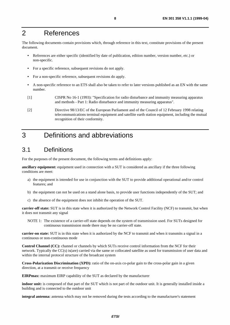
port: particular interface of the specified apparatus with the external electromagnetic environment (figure 1).
APPARATUS
Signal/control port
Earth port
Mains power port
DC power port
Enclosure port
Antenna Port
Earth portTelecom Port
Figure 1: Examples of ports
removable antenna: antenna which may be removed during the tests according to the manufacturer's statement
spurious radiation: any radiation outside the nominated bandwidth
transmission disabled state: SUT is in this state when it is not authorized by the NCF to transmit
voltage axial ratio: voltage axial ratio of an antenna at a transmit or a receive frequency is the ratio r equal to(x + 1)/(x - 1) where x is the square root of the Cross-Polarization Discrimination (XPD) (not expressed in dB)

ETSI
EN 301 358 V1.1.1 (1999-04)10
3.2 AbbreviationsFor the purposes of the present document, the following abbreviations apply:
CC Control ChannelCCF Control Channel Reception FailureCCR Control Channel correctly ReceivedCISPR Comité International Spécial des Perturbations Radioélectriques (International Special Committee
on Radio Interference)CMF Control and Monitoring FunctionsCDMA Code Division Multiple AccessEIRP Equivalent Isotropically Radiated PowerEMC ElectroMagnetic CompatibilityEUT Equipment Under TestFEC Forward Error CorrectionFSS Fixed Satellite ServiceLNB Low Noise Block downconverterNCF Network Control FacilityRF Radio FrequencySMF System Monitoring FailSMP System Monitoring PassSTE Special Test EquipmentSUT Satellite User TerminalTDMA Time Division Multiple AccessTxD Transmission Disable commandTxE Transmission Enable commandXPD Cross-Polarization Discrimination
4 Radio Frequency (RF)Under operational conditions a SUT may dynamically change the occupied bandwidth of the transmitted signal. Foreach occupied bandwidth an EIRPmax and a nominated bandwidth shall be declared by the manufacturer. The following
specifications apply to the SUT for each occupied bandwidth.
4.1 Off-axis spurious radiation
4.1.1 Purpose
To limit the level of interference to terrestrial and satellite radio services.
4.1.2 Specification
The following specifications apply to the SUT transmitting at EIRP values up to and including EIRPmax.
1) The SUT shall not exceed the limits for radiated interference field strength over the frequency range from30 MHz to 1 000 MHz specified in table 1.
Table 1: Limits of radiated field strength at a test distance of 10 m
Frequency range MHz Quasi-peak limits dBµV/m30 to 230 30
230 to 1 000 37
The lower limits shall apply at the transition frequency.
ETSI
EN 301 358 V1.1.1 (1999-04)11
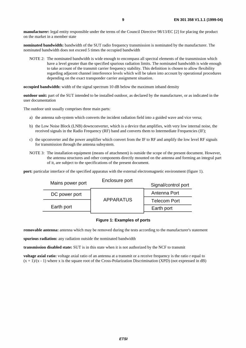
2) When the SUT is in the "Transmission disabled" state, the off-axis spurious EIRP from the SUT, in any 100 kHzband, shall not exceed the limits in table 2, for all off-axis angles greater than 7°.
Table 2: Limits of spurious EIRP - "Transmission disabled" state
Frequency band EIRP limit (dBpW)1,0 GHz to 2,0 GHz 42
2,0 GHz to 10,7 GHz 4810,7 GHz to 21,2 GHz 5421,2 GHz to 40 GHz 60
The lower limits shall apply at the transition frequency.
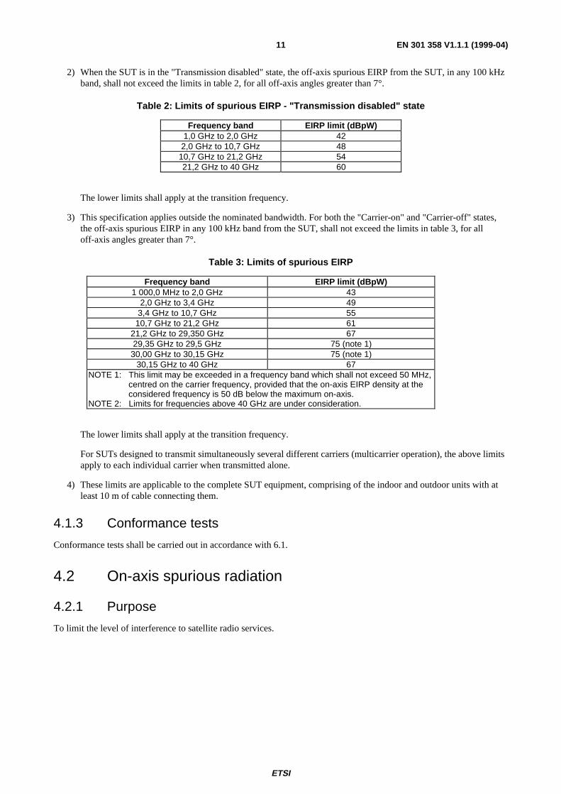
3) This specification applies outside the nominated bandwidth. For both the "Carrier-on" and "Carrier-off" states,the off-axis spurious EIRP in any 100 kHz band from the SUT, shall not exceed the limits in table 3, for alloff-axis angles greater than 7°.
Table 3: Limits of spurious EIRP
Frequency band EIRP limit (dBpW)1 000,0 MHz to 2,0 GHz 43
2,0 GHz to 3,4 GHz 493,4 GHz to 10,7 GHz 55
10,7 GHz to 21,2 GHz 6121,2 GHz to 29,350 GHz 6729,35 GHz to 29,5 GHz 75 (note 1)
30,00 GHz to 30,15 GHz 75 (note 1)30,15 GHz to 40 GHz 67
NOTE 1: This limit may be exceeded in a frequency band which shall not exceed 50 MHz,centred on the carrier frequency, provided that the on-axis EIRP density at theconsidered frequency is 50 dB below the maximum on-axis.
NOTE 2: Limits for frequencies above 40 GHz are under consideration.
The lower limits shall apply at the transition frequency.
For SUTs designed to transmit simultaneously several different carriers (multicarrier operation), the above limitsapply to each individual carrier when transmitted alone.
4) These limits are applicable to the complete SUT equipment, comprising of the indoor and outdoor units with atleast 10 m of cable connecting them.
4.1.3 Conformance tests
Conformance tests shall be carried out in accordance with 6.1.
4.2 On-axis spurious radiation
4.2.1 Purpose
To limit the level of interference to satellite radio services.
ETSI
EN 301 358 V1.1.1 (1999-04)12
4.2.2 Specification
4.2.2.1 "Carrier-on" state
The following specification applies to the SUT transmitting at EIRP values up to EIRPmax.
In the 29,5 GHz to 30,0 GHz band the EIRP spectral density of the spurious radiation outside the nominated bandwidthshall not exceed 4 - 10 log M dBW in any 100 kHz band.
NOTE 1: Some satellite operators may require more stringent limits.
In a bandwidth of 5 times the occupied bandwidth centred on the carrier centre frequency, the EIRP spectral density ofthe spurious radiation outside the nominated bandwidth, shall not exceed 18 - 10 log M dBW in any 100 kHz band.
M is the maximum number of SUTs which are expected to transmit simultaneously in the same carrier frequency band.This number shall not be exceeded for more than 0,01 % of the time. The value of M and the operational conditions ofthe system shall be declared by the manufacturer.
NOTE 2: The on-axis spurious radiation, outside the 29,5 GHz to 30,0 GHz band, are indirectly limited bysubclause 4.1.2. Consequently no specification is needed.
NOTE 3: Intermodulation limits inside the band 29,5 GHz to 30,0 GHz are to be determined by system design andare subject to satellite operator specifications.
For SUT designed to transmit simultaneously several different carriers (multicarrier operation), the above limits onlyapply to each individual carrier when transmitted alone.
4.2.2.2 "Carrier-off" and "Transmission disabled" state
In the 29,5 GHz to 30,0 GHz band the EIRP spectral density of the spurious radiation outside the nominated bandwidthshall not exceed -21 dBW in any 100 kHz band.
NOTE: Some satellite operators may require more stringent limits.
4.2.3 Conformance tests
Conformance tests shall be carried out in accordance with 6.2.
4.3 Off-axis EIRP emission density within the band
4.3.1 Purpose
Protection of other satellite (uplink) systems.
4.3.2 Specification
The following specifications apply to the SUT transmitting at EIRP values up to EIRPmax.
The maximum EIRP in any 40 kHz band within the nominated bandwidth of the co-polarized component in anydirection φ degrees from the antenna main beam axis shall not exceed the following limits:
19 - 25 log φ - 10 log N dBW for 1,8° ≤ φ ≤ 7,0°;
-2 - 10 log N dBW for 7,0° < φ ≤ 9,2°;
22 - 25 log φ - 10 log N dBW for 9,2° < φ ≤ 48°;
-10 - 10 log N dBW for φ > 48°.
ETSI
EN 301 358 V1.1.1 (1999-04)13
Where φ is the angle, in degrees, between the main beam axis and the direction considered. For systems in which morethan one SUT are expected to transmit simultaneously in the same 40 kHz band, e.g. for systems employing CDMA, themaximum EIRP values above are decreased by 10 log (N) dB, where N is the number of SUTs in the receive beam ofthe satellite to which these SUTs are communicating and which are expected to transmit simultaneously in the samefrequency within that beam. This number shall be declared by the manufacturer.
NOTE: N = 1 in a TDMA system.
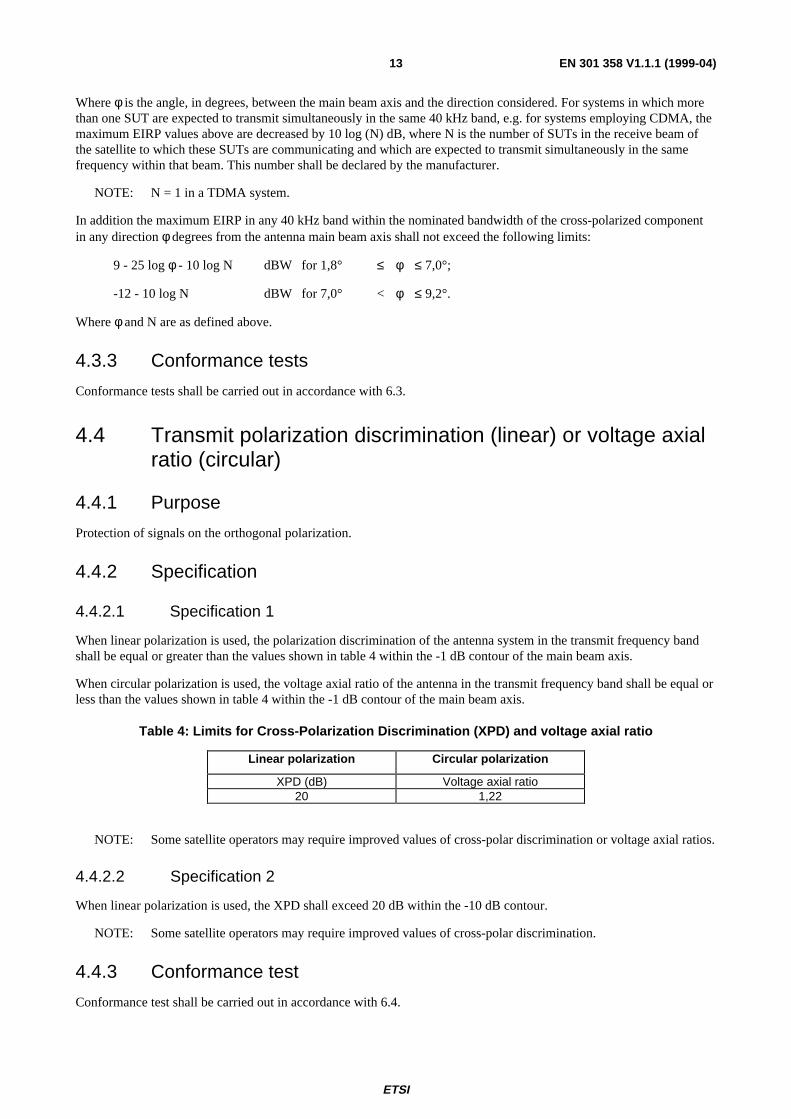
In addition the maximum EIRP in any 40 kHz band within the nominated bandwidth of the cross-polarized componentin any direction φ degrees from the antenna main beam axis shall not exceed the following limits:
9 - 25 log φ - 10 log N dBW for 1,8° ≤ φ ≤ 7,0°;
-12 - 10 log N dBW for 7,0° < φ ≤ 9,2°.
Where φ and N are as defined above.
4.3.3 Conformance tests
Conformance tests shall be carried out in accordance with 6.3.
4.4 Transmit polarization discrimination (linear) or voltage axialratio (circular)
4.4.1 Purpose
Protection of signals on the orthogonal polarization.
4.4.2 Specification
4.4.2.1 Specification 1
When linear polarization is used, the polarization discrimination of the antenna system in the transmit frequency bandshall be equal or greater than the values shown in table 4 within the -1 dB contour of the main beam axis.
When circular polarization is used, the voltage axial ratio of the antenna in the transmit frequency band shall be equal orless than the values shown in table 4 within the -1 dB contour of the main beam axis.
Table 4: Limits for Cross-Polarization Discrimination (XPD) and voltage axial ratio
Linear polarization Circular polarization
XPD (dB) Voltage axial ratio20 1,22
NOTE: Some satellite operators may require improved values of cross-polar discrimination or voltage axial ratios.
4.4.2.2 Specification 2
When linear polarization is used, the XPD shall exceed 20 dB within the -10 dB contour.
NOTE: Some satellite operators may require improved values of cross-polar discrimination.
4.4.3 Conformance test
Conformance test shall be carried out in accordance with 6.4.

ETSI
EN 301 358 V1.1.1 (1999-04)14
4.5 Antenna transmit gain pattern (co-polar and cross-polar)
4.5.1 Purpose
Protection of other satellite (uplink) systems.
4.5.2 Specification
The gain G(Φ) in dB relative to an isotropic antenna shall not exceed these limits:
29 - 25 log Φ for 1,8° < Φ ≤ 7,0°;
8 for 7,0° < Φ ≤ 9,2°;
32 - 25 log Φ for 9,2° < Φ ≤ 48°;
0 for Φ > 48°;
Additionally, the cross-polar gain G(Φ) in dB relative to an isotropic antenna shall not exceed these limits:
19 - 25 log Φ for 1,8° < Φ ≤ 7,0°;
-2 for 7,0° < Φ ≤ 9,2°;
4.5.3 Conformance tests
Conformance tests shall be carried out in accordance with 6.3.
4.6 Carrier suppression
4.6.1 Purpose
To allow for the satisfactory suppression of transmissions of a SUT by the NCF.
4.6.2 Specification
When the SUT is in the "Transmission disabled" state the on-axis EIRP shall not exceed 4 dBW in any 100 kHz bandwithin the nominated bandwidth.
4.6.3 Conformance tests
Conformance tests shall be carried out in accordance with 6.5.
4.7 Antenna pointing accuracy
4.7.1 Purpose
Protection of signals to and from the same and adjacent satellites.
4.7.2 Specification
a) Pointing stability:
Under the condition of 100 km/h maximum wind speed, with gusts of 130 km/h lasting 3 seconds, the installationshall not show any sign of permanent distortion and shall not need repointing after the application of the windload.
ETSI
EN 301 358 V1.1.1 (1999-04)15
b) Pointing accuracy capability:
The antenna sub-system alignment facilities shall enable the main beam axis to be adjusted and fixed with anaccuracy better than or equal to 10 % of the antenna transmit main beam minimum half power beamwidth orbetter than or equal to 0,1°, whichever is the greater angle.
c) Polarization angle alignment capability for linear polarization:
The polarization angle shall be continuously adjustable within the operational range as declared by themanufacturer.
It shall be possible to fix the transmit antenna polarization angle with an accuracy of at least 1°.
When transmission and reception is with linear polarization receive and corresponding transmit polarizationplanes shall not deviate by more than 1° from the nominal value declared by the manufacturer.
4.7.3 Conformance tests
Conformance tests shall be carried out in accordance with 6.6.
5 Control and Monitoring Functions (CMF)The following minimum set of CMFs shall be implemented in SUTs in order to minimize the probability that theyoriginate unwanted transmissions that may give rise to harmful interference to other systems.
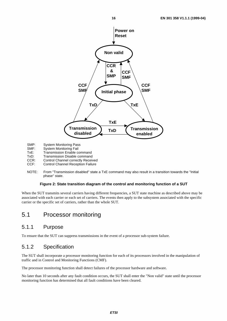
For the purpose of the present document the states of the SUT are:
- "Non valid";
- "Initial phase";
- "Transmission disabled"; and
- "Transmission enabled".
In the "Non-valid" state and in the "Transmission disable" state the SUT shall not transmit. In the"Transmission-enabled" state the SUT is allowed to transmit. In the "Initial phase" state the SUT is only allowed totransmit initial bursts.
Under any fault condition when the SUT transmissions are being suppressed the EIRP limits for the "Transmissiondisabled" state shall apply.
ETSI
EN 301 358 V1.1.1 (1999-04)16
TxE
Transmissiondisabled
Transmissionenabled
Non valid
Initial phase
TxD
TxE
CCR&
SMP
TxD
CCFSMF
CCFSMF
CCFSMF
Power onReset
SMP: System Monitoring PassSMF: System Monitoring FailTxE: Transmission Enable commandTxD: Transmission Disable commandCCR: Control Channel correctly ReceivedCCF: Control Channel Reception Failure
NOTE: From "Transmission disabled" state a TxE command may also result in a transition towards the "Initialphase" state.
Figure 2: State transition diagram of the control and monitoring function of a SUT
When the SUT transmits several carriers having different frequencies, a SUT state machine as described above may beassociated with each carrier or each set of carriers. The events then apply to the subsystem associated with the specificcarrier or the specific set of carriers, rather than the whole SUT.
5.1 Processor monitoring
5.1.1 Purpose
To ensure that the SUT can suppress transmissions in the event of a processor sub-system failure.
5.1.2 Specification
The SUT shall incorporate a processor monitoring function for each of its processors involved in the manipulation oftraffic and in Control and Monitoring Functions (CMF).
The processor monitoring function shall detect failures of the processor hardware and software.
No later than 10 seconds after any fault condition occurs, the SUT shall enter the "Non valid" state until the processormonitoring function has determined that all fault conditions have been cleared.
ETSI
EN 301 358 V1.1.1 (1999-04)17
5.1.3 Conformance tests
Conformance tests shall be carried out in accordance with 6.7.2.
5.2 Transmit subsystem monitoring
5.2.1 Purpose
To ensure the correct operation of the transmit frequency generation sub-system and to inhibit transmissions should thesub-system fail.
5.2.2 Specification
The SUT shall monitor the operation of its transmit frequency generation sub-system.
No later than 1 second after any fault condition of the transmit frequency generation sub-system occurs, the SUT shallenter the "Non-valid" state until the transmit sub-system monitoring function has determined that all fault conditionshave been cleared.
5.2.3 Conformance tests
Conformance tests shall be carried out in accordance with 6.7.3.
5.3 Power-on/Reset
5.3.1 Purpose
To demonstrate that the SUT achieves a controlled non-transmitting state following the powering of the unit, or theoccurrence of a reset made by a local operator when this function is implemented.
5.3.2 Specification
Following a manual reset, when this function is implemented, the SUT shall enter the "Non-valid" state.
During and following "power-on" the SUT shall remain in the "Non-valid" state.
5.3.3 Conformance tests
Conformance tests shall be carried out in accordance with 6.7.4.
ETSI
EN 301 358 V1.1.1 (1999-04)18
5.4 Control Channel (CC) reception
5.4.1 Purpose
To ensure that the SUT can not transmit unless it correctly receives the CC messages from the NCF.
5.4.2 Specification
a) The SUT shall enter the "Non-valid" state immediately after a period not exceeding 10 seconds without correctreception of the CC from the NCF.
b) The SUT shall remain in the "Non-valid" state as long as the CC messages from the NCF are not received.
c) From the "Non-valid" state the SUT may enter the "Initial phase" state if the following conditions are met:
- the CC messages from the NCF are correctly received; and
- no fault conditions are present.
5.4.3 Conformance tests
Conformance tests shall be carried out in accordance with subclause 6.7.5.
5.5 Network control commands
5.5.1 Purpose
These requirements ensure that the SUT is capable of:
a) retaining a unique identification in the network;
b) receiving commands from the NCF through its CC(s) and executing those commands.
5.5.2 Specification
The SUT shall hold, in non-volatile memory, its unique identification code in the network.
The SUT shall be capable of receiving through its CCs dedicated messages (addressed to the SUT) from the NCF, andwhich contain:
- transmission enable commands; and
- transmission disable commands.
From "Initial phase" or "Transmission enabled" states once a transmission disable command is received, within10 seconds the SUT shall enter into, and shall remain in, the "Transmission disabled" state until the transmission disablecommand is superseded by a subsequent transmission enable command.
5.5.3 Conformance test
Conformance tests shall be carried out in accordance with 6.7.6.
ETSI
EN 301 358 V1.1.1 (1999-04)19
5.6 Initial burst transmission
5.6.1 Purpose
Restriction on the initial burst transmission are necessary to limit disturbance to other services.
5.6.2 Specification
For systems where no transmission enable command is foreseen without request from the SUT, in the "Initial phase"state the SUT may transmit initial bursts.
a) The duty cycle of the burst retransmission shall not exceed 0,2 %.
b) Each burst shall not carry more than 256 data bytes excluding the burst preambles and the FEC coding bits.
5.6.3 Conformance tests
Conformance tests shall be carried out in accordance with 6.7.7.
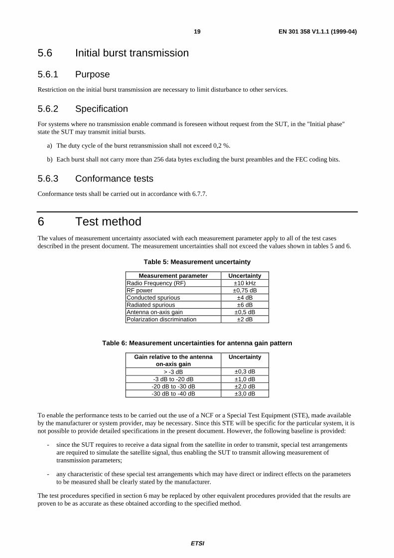
6 Test methodThe values of measurement uncertainty associated with each measurement parameter apply to all of the test casesdescribed in the present document. The measurement uncertainties shall not exceed the values shown in tables 5 and 6.
Table 5: Measurement uncertainty
Measurement parameter UncertaintyRadio Frequency (RF) ±10 kHzRF power ±0,75 dBConducted spurious ±4 dBRadiated spurious ±6 dBAntenna on-axis gain ±0,5 dBPolarization discrimination ±2 dB
Table 6: Measurement uncertainties for antenna gain pattern
Gain relative to the antennaon-axis gain
Uncertainty
> -3 dB ±0,3 dB-3 dB to -20 dB ±1,0 dB
-20 dB to -30 dB ±2,0 dB-30 dB to -40 dB ±3,0 dB
To enable the performance tests to be carried out the use of a NCF or a Special Test Equipment (STE), made availableby the manufacturer or system provider, may be necessary. Since this STE will be specific for the particular system, it isnot possible to provide detailed specifications in the present document. However, the following baseline is provided:
- since the SUT requires to receive a data signal from the satellite in order to transmit, special test arrangementsare required to simulate the satellite signal, thus enabling the SUT to transmit allowing measurement oftransmission parameters;
- any characteristic of these special test arrangements which may have direct or indirect effects on the parametersto be measured shall be clearly stated by the manufacturer.
The test procedures specified in section 6 may be replaced by other equivalent procedures provided that the results areproven to be as accurate as these obtained according to the specified method.

ETSI
EN 301 358 V1.1.1 (1999-04)20
All tests with carrier-on shall be undertaken with the transmitter operating at maximum power and with the maximumtransmit burst rate, where applicable, which shall be declared by the manufacturer.
If the EUT is a SUT that has had hardware and/or software modification(s) performed by the manufacturer for thesetests then full documentation of such modification(s) shall be provided to prove that the modification(s) will simulate therequired test condition. Such modification(s) shall be proved to allow the SUT to operate without its main characteristicsbeing changed.
The SUT antenna shall not be rotated around its main beam axis.
All technical characteristics and operational conditions declared by the manufacturer shall be entered in the test report.
6.1 Off-axis spurious radiationThe tests for the specification in 4.3 shall be limited to the carrier-on state.
6.1.1 Test method
An EUT with antenna is a SUT with its antenna comprising both the indoor and outdoor units interconnected by 10 m ofcable. An EUT without antenna is a SUT with the removable antenna removed. It comprises both the indoor and outdoorunits, up to the antenna flange, interconnected by 10 m of cable. The connecting cable between the indoor and theoutdoor units shall be of the same type as specified by the manufacturer in the installation manual. The type of cableused shall be entered in the test report.
The EUT shall be terminated with matched impedance at the terrestrial ports if recommended by the manufacturer in theuser documentation and if there is no associated equipment connected to each port.
For frequencies up to 80 MHz the measuring antenna shall be a balanced dipole with a length equal to the 80 MHzresonant length and shall be matched to the feeder by a suitable balanced transforming device. Measurements with broadband antennas is also possible provided that the test site has been validated according to CISPR 16-1 [1].
For frequencies between 80 MHz and 1 000 MHz the measuring antenna shall be a balanced dipole which shall beresonant in length. Measurements with broad band antennas is also possible provided that the test site has been validatedaccording to CISPR 16-1 [1].
For frequencies above 1 000 MHz the antenna shall be a horn radiator of known gain/frequency characteristics. Whenused for reception the antenna and any associated amplification system shall have an amplitude/frequency responsewithin ±2 dB of the combined calibration curves across the measurement frequency range considered for the antenna.The antenna is mounted on a support capable of allowing the antenna to be used in either horizontal or verticalpolarization and at the specified height.
6.1.1.1 Up to 1 000 MHz
6.1.1.1.1 Test site
The test shall be performed either in an open area test site, a semi-anechoic chamber or an anechoic chamber. Ambientnoise levels shall be at least 6 dB below the applicable unwanted emissions limit.
The open area test site shall be flat, free of overhead wires and nearby reflecting structures, sufficiently large to permitaerial placement at the specified measuring distance and provide adequate separation between aerial, test unit andreflecting structures, according to CISPR 16-1 [1].
For both the open area test site and the semi-anechoic chamber a metal ground plane shall be inserted on the naturalground plane and it shall extend at least 1 m beyond the perimeter of the EUT at one end and at least 1 m beyond themeasuring antenna at the other end.
The distance between the EUT and measuring antenna should be 10 m. For measurements at a different distance aninverse proportionality factor of 20 dB per decade shall be used to normalize the measured data to the specified distancefor determining compliance. Care should be taken in measurement of large test units at 3 m at frequencies near 30 MHzdue to near field effects.
ETSI
EN 301 358 V1.1.1 (1999-04)21
6.1.1.1.2 Measuring receivers
Measuring receivers shall conform to the following characteristics:
- the response to a constant amplitude sine wave signal shall remain within ±1 dB across the frequency range ofinterest;
- quasi-peak detection shall be used in a -6 dB bandwidth of 120 kHz;
- the receiver shall be operated below the 1 dB compression point.
6.1.1.1.3 Procedure
a) The EUT shall be an EUT with antenna or, preferably, without antenna but with the antenna flange terminated bya dummy load.
b) The EUT shall be in the carrier-on state.
c) The EUT shall be rotated through 360° and, except in an anechoic chamber, the measuring antenna shall berotated and height varied from 1 m to 4 m above the ground plane to determine the maximum emission.
d) All identified spurious radiation shall be measured and noted in frequency and level.
6.1.1.2 Above 1 000 MHz
The spectrum analyser resolution bandwidth shall be set to the specified measuring bandwidth or as close as possible. Ifthe resolution bandwidth is different from the specified measuring bandwidth, bandwidth correction shall be performedfor the noise-like wideband spurious.
For an EUT with antenna the tests shall be performed in two stages for both the carrier-on and carrier-off states:
Procedure a): Identification of the significant frequencies of spurious radiation.
Procedure b): Measurement of radiated power levels of identified spurious radiation.
For an EUT without antenna the tests shall be performed in three stages for both the carrier-on and carrier-off states:
Procedure a): Identification of the significant frequencies of spurious radiation.
Procedure b): Measurement of radiated power levels of identified spurious radiation.
Procedure c): Measurement of conducted spurious radiation radiated through the antenna flange.
6.1.1.2.1 Identification of the significant frequencies of spurious radiation
6.1.1.2.1.1 Test site
The identification of frequencies emitting from the EUT shall be performed either in an anechoic chamber, an open areatest site or a semi-anechoic chamber with the test antenna close to the EUT and at the same height as the volume centreof the EUT.
ETSI
EN 301 358 V1.1.1 (1999-04)22
6.1.1.2.1.2 Procedure
a) The EUT shall be in the carrier-off state.
b) For an EUT with antenna the main beam of the antenna shall have an angle of elevation of 7°, and, for an EUTwithout antenna the antenna flange shall be terminated by a dummy load.
c) The receivers shall scan the frequency band while the EUT revolves.
d) The EUT shall be rotated though 360° and the frequency of any spurious signals noted for further investigation.
e) For an EUT with antenna the test shall be repeated with the test antenna being in the opposite polarization.
f) The test shall be repeated in the carrier-on state while transmitting one modulated carrier at maximum power.
6.1.1.2.2 Measurement of radiated power levels of identified spurious radiation
6.1.1.2.2.1 Test site
The measurement of each spurious radiation noted during procedure a) of the test shall be performed on a test site that isfree from reflecting objects, i.e. either an open-area test site, a semi-anechoic chamber or an anechoic chamber.
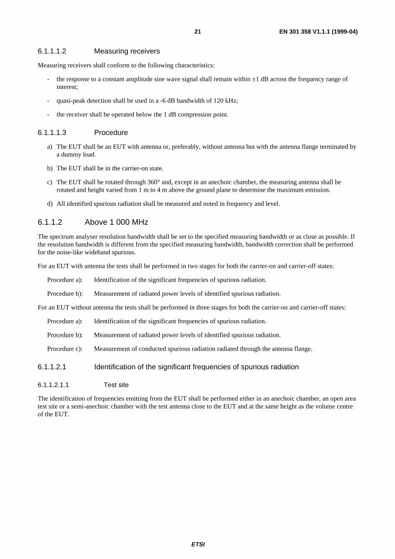
6.1.1.2.2.2 Procedure
EUT
Substitutionantenna
Measuring antenna
Signalgenerator
SUTSpectrumanalyser
Filters
Figure 3: Test arrangement - Spurious radiation measurement above 1 000 MHzfor an EUT with antenna
ETSI
EN 301 358 V1.1.1 (1999-04)23
EUT
Substitutionantenna
Measuring antenna
Signalgenerator
SUTSpectrumanalyser
Filters Testload
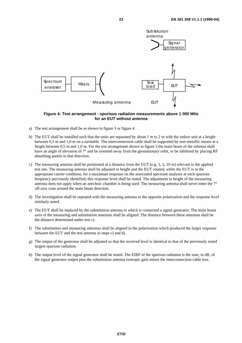
Figure 4: Test arrangement - spurious radiation measurements above 1 000 MHzfor an EUT without antenna
a) The test arrangement shall be as shown in figure 3 or figure 4.
b) The EUT shall be installed such that the units are separated by about 1 m to 2 m with the indoor unit at a heightbetween 0,5 m and 1,0 m on a turntable. The interconnection cable shall be supported by non-metallic means at aheight between 0,5 m and 1,0 m. For the test arrangement shown in figure 3 the main beam of the antenna shallhave an angle of elevation of 7° and be oriented away from the geostationary orbit, or be inhibited by placing RFabsorbing panels in that direction.
c) The measuring antenna shall be positioned at a distance from the EUT (e.g. 3, 5, 10 m) relevant to the appliedtest site. The measuring antenna shall be adjusted in height and the EUT rotated, while the EUT is in theappropriate carrier condition, for a maximum response on the associated spectrum analyser at each spuriousfrequency previously identified, this response level shall be noted. The adjustment in height of the measuringantenna does not apply when an anechoic chamber is being used. The measuring antenna shall never enter the 7°off-axis cone around the main beam direction.
d) The investigation shall be repeated with the measuring antenna in the opposite polarization and the response levelsimilarly noted.
e) The EUT shall be replaced by the substitution antenna to which is connected a signal generator. The main beamaxes of the measuring and substitution antennas shall be aligned. The distance between these antennas shall bethe distance determined under test c).
f) The substitution and measuring antennas shall be aligned in the polarization which produced the larger responsebetween the EUT and the test antenna in steps c) and d).
g) The output of the generator shall be adjusted so that the received level is identical to that of the previously notedlargest spurious radiation.
h) The output level of the signal generator shall be noted. The EIRP of the spurious radiation is the sum, in dB, ofthe signal generator output plus the substitution antenna isotropic gain minus the interconnection cable loss.
ETSI
EN 301 358 V1.1.1 (1999-04)24
6.1.1.2.3 Measurement of conducted spurious radiation at the antenna flange
6.1.1.2.3.1 Test site
There are no requirements for the test site to be used for this test.
6.1.1.2.3.2 Procedure
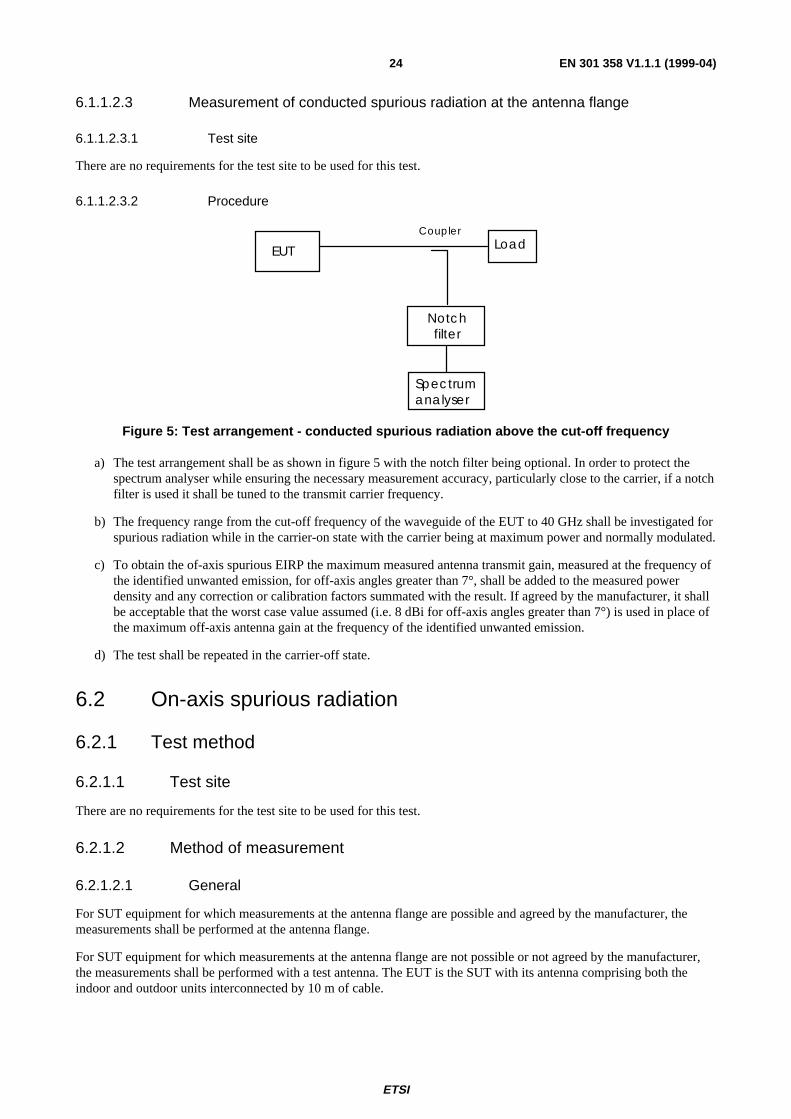
Spectrumanalyser
EUT Load
Notchfilter
Coupler
Figure 5: Test arrangement - conducted spurious radiation above the cut-off frequency
a) The test arrangement shall be as shown in figure 5 with the notch filter being optional. In order to protect thespectrum analyser while ensuring the necessary measurement accuracy, particularly close to the carrier, if a notchfilter is used it shall be tuned to the transmit carrier frequency.
b) The frequency range from the cut-off frequency of the waveguide of the EUT to 40 GHz shall be investigated forspurious radiation while in the carrier-on state with the carrier being at maximum power and normally modulated.
c) To obtain the of-axis spurious EIRP the maximum measured antenna transmit gain, measured at the frequency ofthe identified unwanted emission, for off-axis angles greater than 7°, shall be added to the measured powerdensity and any correction or calibration factors summated with the result. If agreed by the manufacturer, it shallbe acceptable that the worst case value assumed (i.e. 8 dBi for off-axis angles greater than 7°) is used in place ofthe maximum off-axis antenna gain at the frequency of the identified unwanted emission.
d) The test shall be repeated in the carrier-off state.
6.2 On-axis spurious radiation
6.2.1 Test method
6.2.1.1 Test site
There are no requirements for the test site to be used for this test.
6.2.1.2 Method of measurement
6.2.1.2.1 General
For SUT equipment for which measurements at the antenna flange are possible and agreed by the manufacturer, themeasurements shall be performed at the antenna flange.
For SUT equipment for which measurements at the antenna flange are not possible or not agreed by the manufacturer,the measurements shall be performed with a test antenna. The EUT is the SUT with its antenna comprising both theindoor and outdoor units interconnected by 10 m of cable.
ETSI
EN 301 358 V1.1.1 (1999-04)25
6.2.1.2.2 Method of measurement at the antenna flange
a) The test arrangement shall be as shown in figure 5 with the notch filter being optional. In order to protect thespectrum analyser while ensuring the necessary measurement accuracy, particularly close to the carrier, if a notchfilter is used it shall be tuned to the transmit carrier frequency.
b) The EUT shall transmit one modulated carrier continuously, or at its maximum burst rate where applicable,centred on a frequency as close to the lower limit of the operating frequency band of the EUT as possible. TheEUT shall be operated at EIRPmax. The frequency range 29,5 GHz to 30,0 GHz shall be investigated.
c) Due to the proximity of the carrier the spectrum analyser resolution bandwidth shall be set to a measurementbandwidth of 3 kHz, or as close as possible. If the measurement bandwidth is different from the specifiedmeasurement bandwidth, bandwidth correction shall be performed for noise-like wideband spurious radiation.
d) To obtain the on-axis spurious EIRP, the antenna transmit gain shall be added to any figure obtained in the abovemeasurement and any correction or calibration factor summated with the result. The antenna gain shall be asmeasured in subclause 6.3.1.2 at the closest frequency to the spurious frequency.
e) The tests in b) to e) shall be repeated with a transmit frequency in the centre of the operating frequency band.
f) The tests in b) to e) shall be repeated with a transmit frequency as close to the upper limit of the operatingfrequency band of the EUT as possible.
g) The tests in b) to f) shall be repeated in the carrier-off state.
6.2.1.2.3 Method of measurement for an EUT with antenna
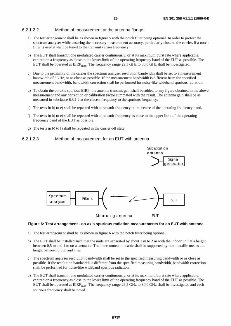
EUT
Substitutionantenna
Measuring antenna
Signalgenerator
SUTSpectrumanalyser
Filters
Figure 6: Test arrangement - on-axis spurious radiation measurements for an EUT with antenna
a) The test arrangement shall be as shown in figure 6 with the notch filter being optional.
b) The EUT shall be installed such that the units are separated by about 1 m to 2 m with the indoor unit at a heightbetween 0,5 m and 1 m on a turntable. The interconnection cable shall be supported by non-metallic means at aheight between 0,5 m and 1 m.
c) The spectrum analyser resolution bandwidth shall be set to the specified measuring bandwidth or as close aspossible. If the resolution bandwidth is different from the specified measuring bandwidth, bandwidth correctionshall be performed for noise-like wideband spurious radiation.
d) The EUT shall transmit one modulated carrier continuously, or at its maximum burst rate where applicable,centred on a frequency as close to the lower limit of the operating frequency band of the EUT as possible. TheEUT shall be operated at EIRPmax. The frequency range 29,5 GHz to 30,0 GHz shall be investigated and each
spurious frequency shall be noted.

ETSI
EN 301 358 V1.1.1 (1999-04)26
e) Due to the proximity of the carrier the spectrum analyser resolution bandwidth shall be set to a measurementbandwidth of 3 kHz, or lower. If the measurement bandwidth is different from the specified measurementbandwidth, bandwidth correction shall be performed for noise-like wideband spurious radiation.
f) The measuring antenna shall be positioned at a distance from the EUT (e.g. 3, 5, 10 m) relevant to the appliedtest site and shall be aligned with the EUT antenna for the transmit frequency. The measuring antenna shall beadjusted in height, while the EUT is in the appropriate carrier condition, for a maximum response on theassociated spectrum analyser at each spurious frequency previously identified, this response level shall be noted.The adjustment in height of the measuring antenna does not apply when an anechoic chamber is being used.
g) The EUT shall be replaced by a representative substitution antenna to which a signal generator is connected. Themain beam axes of the measuring and substitution antennas shall be aligned. The distance between these antennasshall be the distance determined under test f).
h) The substitution and measuring antennas shall be aligned to that polarization which produced the largest responsebetween the EUT and the test antenna.
j) The output of the generator shall be adjusted so that the received level is identical to that of the previously notedlargest spurious radiation.
k) The output level of the signal generator shall be noted. The EIRP of the on-axis spurious radiation is the sum, indB, of the signal generator output plus the substitution antenna isotropic gain minus the interconnection cableloss.
l) The tests in d) to k) shall be repeated with a transmit frequency in the centre of the operating frequency band.
m) The tests in d) to k) shall be repeated with a transmit frequency as close to the upper limit of the operatingfrequency band of the EUT as possible.
n) The tests in b) to m) shall be repeated in the carrier-off state.
6.3 Off-axis EIRP emission density within the bandOff-axis EIRP emission density (co-polar and cross-polar) within the band 29,5 GHz to 30,0 GHz.
6.3.1 Test method
To ascertain the off-axis EIRP it is necessary to know the transmit power density and antenna transmit radiation pattern.To ascertain the radiation pattern it is necessary to know the antenna transmit gain.
The following three measurement procedures shall be performed:
a) transmit output power density (dBW/40 kHz);
b) antenna transmit gain (dBi);
c) antenna transmit radiation patterns (dBi).
6.3.1.1 Transmit output power density
For the purposes of the present document, maximum output power is defined as the power delivered by the transmittingequipment to the antenna flange to achieve EIRPmax.
For the purposes of this test the EUT is defined as the indoor unit and that part of the outdoor unit up to the antennaflange.
6.3.1.1.1 Test site
There are no requirements for the test site to be used for this test.

ETSI
EN 301 358 V1.1.1 (1999-04)27
6.3.1.1.2 Method of measurement
Spectrumanalyser
EUT LoadCoupler
Figure 7: Test arrangement - transmit output power density measurement
a) The test arrangement shall be as shown in figure 7.
b) The EUT shall transmit one carrier modulated with data. For burst mode transmission the EUT shall transmit atits maximum burstrate. The maximum power supplied to the antenna flange shall be measured in dBW/40 kHz.The coupling factor of the test coupler at the test frequency and the attenuation of any necessary waveguideadapter shall be taken into account. The resolution bandwidth of the spectrum analyser shall be set as close aspossible to the specified measuring bandwidth. If the resolution bandwidth is different from the specifiedbandwidth then bandwidth correction shall be performed.
c) The test shall be repeated for each data rate supported by the SUT.
6.3.1.2 Antenna transmit gain
6.3.1.2.1 General
For the purposes of the present document, the antenna transmit gain is defined as the ratio, expressed in decibels (dBi),of the power that would have to be supplied to the reference antenna, i.e. an isotropic radiator isolated in space, to thepower supplied to the antenna being considered, so that they produce the same field strength at the same distance in thesame direction. Unless otherwise specified the gain is for the direction of maximum radiation.
For the purposes of this test the EUT is defined as that part of the outdoor unit which comprises the antenna and itsflange. The antenna may include the reflector(s), feed, support struts and an enclosure of equal weight/distribution toany electrical equipment normally housed with the feed at the antenna focal point.
6.3.1.2.2 Test site
This test shall be performed on either an outdoor far-field test site or compact test range. However, if the near-fieldscanner technology to convert near-field measurements to far-field results is proven and sufficiently accurate byreference to tests taken in both regions then antenna measurements may be taken in the near field. Fully automatedsystems can be used for these tests providing that the results can be proven to be as accurate as if they were doneaccording to the specified method.
ETSI
EN 301 358 V1.1.1 (1999-04)28
6.3.1.2.3 Method of measurement
Signalgenerator
Testtransmitter
Testreceiver
X-YPlotter
EUT
SubstitutionAntenna
Test antenna
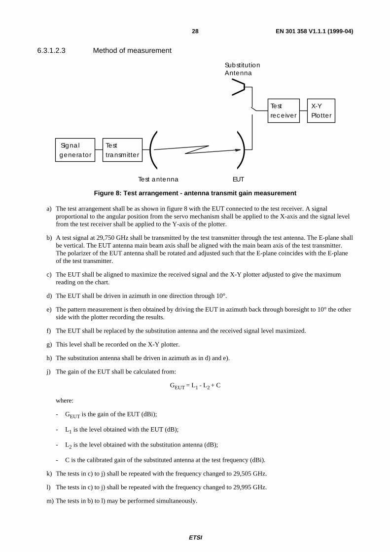
Figure 8: Test arrangement - antenna transmit gain measurement
a) The test arrangement shall be as shown in figure 8 with the EUT connected to the test receiver. A signalproportional to the angular position from the servo mechanism shall be applied to the X-axis and the signal levelfrom the test receiver shall be applied to the Y-axis of the plotter.
b) A test signal at 29,750 GHz shall be transmitted by the test transmitter through the test antenna. The E-plane shallbe vertical. The EUT antenna main beam axis shall be aligned with the main beam axis of the test transmitter.The polarizer of the EUT antenna shall be rotated and adjusted such that the E-plane coincides with the E-planeof the test transmitter.
c) The EUT shall be aligned to maximize the received signal and the X-Y plotter adjusted to give the maximumreading on the chart.
d) The EUT shall be driven in azimuth in one direction through 10°.
e) The pattern measurement is then obtained by driving the EUT in azimuth back through boresight to 10° the otherside with the plotter recording the results.
f) The EUT shall be replaced by the substitution antenna and the received signal level maximized.
g) This level shall be recorded on the X-Y plotter.
h) The substitution antenna shall be driven in azimuth as in d) and e).
j) The gain of the EUT shall be calculated from:
GEUT = L1 - L2 + C
where:
- GEUT is the gain of the EUT (dBi);
- L1 is the level obtained with the EUT (dB);
- L2 is the level obtained with the substitution antenna (dB);
- C is the calibrated gain of the substituted antenna at the test frequency (dBi).
k) The tests in c) to j) shall be repeated with the frequency changed to 29,505 GHz.
l) The tests in c) to j) shall be repeated with the frequency changed to 29,995 GHz.
m) The tests in b) to l) may be performed simultaneously.

ETSI
EN 301 358 V1.1.1 (1999-04)29
6.3.1.3 Antenna transmit radiation patterns
6.3.1.3.1 General
For the purposes of the present document, the antenna transmit radiation patterns are diagrams relating field strength tothe angle of the direction pointed by the antenna at a constant large distance from the antenna.
For the purposes of this test, the EUT is defined as that part of the outdoor unit which comprises the antenna and itsflange. The antenna includes the reflector(s), feed, support struts and an enclosure of equal weight/distribution to anyelectrical equipment normally housed with the feed at the antenna focal point.
6.3.1.3.2 Test site
This test shall be performed on either an outdoor far-field test site or compact test range. However, if the near-fieldscanner technology to convert near-field measurements to far-field results is proven and sufficiently accurate byreference to tests taken in both regions then antenna measurements may be taken in the near field. Fully automatedsystems can be used for these tests providing that the results can be proven to be as accurate as if they were doneaccording to the specified method.
6.3.1.3.3 Test arrangement
SignalGenerator
Testtransmitter
Testreceiver
X-YPlotter
EUTTest Antenna
Figure 9: Test arrangement - antenna transmit radiation pattern measurement
6.3.1.3.4 Co-polar radiation pattern - azimuth
a) The test arrangement shall be as shown in figure 9 with the EUT connected to the test receiver. A signalproportional to the angular position from the servo mechanism shall be applied to the X-axis and the signal levelfrom the test receiver shall be applied to the Y-axis of the plotter.
b) The frequency of the test signal shall be set to 29,750 GHz.
c) The initial E-plane of the test signal radiated by the test transmitter through its antenna shall be vertical for linearpolarization or left hand for circular polarization antennas. The EUT antenna main beam axis shall be alignedwith the main beam axis of the test transmitter. For linear polarization the polarizer of the EUT antenna shall berotated and adjusted such that its E-plane coincides with the E-plane of the test transmitter. Precise co-polarpeaking of the polarization shall be done by observing the cross-polar minimum (fine adjustment).
d) The EUT shall be aligned to maximize the received signal and the X-Y plotter adjusted to give the maximumreading on the chart.
e) The EUT shall be driven in azimuth to -180°.
f) The transmit pattern measurement is then obtained by driving the EUT in azimuth from -180° to +180° with theplotter recording the results.
g) The tests in d) to f) shall be repeated with the frequency changed to 29,505 GHz.
h) The tests in d) to f) shall be repeated with the frequency changed to 29,995 GHz.
j) The tests in b) to h) may be performed simultaneously.
ETSI
EN 301 358 V1.1.1 (1999-04)30
k) The tests in d) to j) shall be repeated with the E-plane of the test signal being horizontal or right hand circular asappropriate. The frequency of the test signal shall be set to 29,750 GHz. For linear polarization the polarizer ofthe EUT antenna shall be rotated and adjusted such that its E-plane coincides with the E-plane of the testtransmitter (giving the minimum cross-polar receive signal). Precise co-polar peaking of the polarization shall bedone by observing the cross-polar minimum.
6.3.1.3.5 Co-polar radiation pattern - elevation
a) The test arrangement shall be as shown in figure 9 with the EUT connected to the test receiver. A signalproportional to the angular position from the servo mechanism shall be applied to the X-axis and the signal levelfrom the test receiver shall be applied to the Y-axis of the plotter.
b) The frequency of the test signal shall be set to 29,750 GHz.
c) The initial E-plane of the test signal radiated by the test transmitter through its antenna shall be vertical for linearpolarization or left-hand for circular polarization antennas. The EUT antenna main beam axis shall be alignedwith the main beam axis of the test transmitter. For linear polarization the polarizer of the EUT antenna shall berotated and adjusted such that its E-plane coincides with the E-plane of the test transmitter. Precise co-polarpeaking of the polarization shall be done by observing the cross-polar minimum (fine adjustment).
d) The EUT shall be aligned to maximize the received signal and the X-Y plotter adjusted to give the maximumreading on the chart.
e) The EUT shall be driven in elevation to -1°.
f) The transmit pattern measurement is then obtained by driving the EUT in elevation from -1° to 70° with theplotter recording the results.
g) The tests in d) to f) shall be repeated with the frequency changed to 29,505 GHz.
h) The tests in d) to f) shall be repeated with the frequency changed to 29,995 GHz.
j) The tests in b) to h) may be performed simultaneously.
k) The tests in d) to j) shall be repeated with the E-plane of the test signal being horizontal. The frequency of thetest signal shall be set to 29,750 GHz. For linear polarization the polarizer of the EUT antenna shall be rotatedand adjusted such that its E-plane coincides with the E-plane of the test transmitter. The EUT antenna main beamaxis shall be aligned with the main beam axis of the test transmitter. Precise co-polar peaking of the polarizationplane shall be done by observing the cross-polar minimum (fine adjustment).
6.3.1.3.6 Cross-polar radiation pattern - azimuth
a) The test arrangement shall be as shown in figure 9 with the EUT connected to the test receiver. A signalproportional to the angular position from the servo mechanism shall be applied to the X-axis and the signal levelfrom the test receiver shall be applied to the Y-axis of the plotter.
b) The frequency of the test signal shall be set to 29,750 GHz.
c) The initial E-plane of the test signal radiated by the test transmitter through its antenna shall be vertical for linearpolarization or left-hand for circular polarization antennas. The EUT antenna main beam axis shall be alignedwith the main beam axis of the test transmitter. For linear polarization the polarizer of the EUT antenna shall berotated and adjusted such that its E-plane is orthogonal to the E-plane of the test transmitter. Precise fineadjustment of the polarization plane shall be done by observing the cross-polar minimum.
d) In order to adjust the X-Y plotter giving the maximum reading on the chart the boresight co-polar receive signalshall be used.
e) The EUT shall be driven in azimuth to -10°.
f) The transmit pattern measurement is then obtained by driving the EUT in azimuth from -10° to +10° with theplotter recording the results.
g) The tests in d) to f) shall be repeated with the frequency changed to 29,505 GHz.

ETSI
EN 301 358 V1.1.1 (1999-04)31
h) The tests in d) to f) shall be repeated with the frequency changed to 29,995 GHz.
j) The tests in b) to h) may be performed simultaneously.
k) The tests in d) to j) shall be repeated with the E-plane of the test signal being horizontal or right hand circular asappropriate. The frequency of the test signal shall be set to 29,750 GHz. The EUT antenna main beam axis shallbe aligned with the main beam axis of the test transmitter. For linear polarization the polarizer of the EUTantenna shall be rotated and adjusted such that its E-plane is orthogonal with the E-plane of the test transmitter.Precise fine adjustment of the polarization plane shall be done by observing the cross-polar minimum.
6.3.1.3.7 Cross-polar radiation pattern - elevation
a) The test arrangement shall be as shown in figure 9 with the EUT connected to the test receiver. A signalproportional to the angular position from the servo mechanism shall be applied to the X-axis and the signal levelfrom the test receiver shall be applied to the Y-axis of the plotter.
b) The frequency of the test signal shall be set to 29,750 GHz.
c) The initial E-plane of the test signal radiated by the test transmitter through its antenna shall be vertical for linearpolarization or left hand for circular polarization antennas. The EUT antenna main beam axis shall be alignedwith the main beam axis of the test transmitter. For linear polarization the polarizer of the EUT antenna shall berotated and adjusted such that its E-plane is orthogonal to the E-plane of the test transmitter. Precise fineadjustment of the polarization plane shall be done by observing the cross-polar minimum.
d) In order to adjust the X-Y plotter giving the maximum reading on the chart the boresight co-polar receive signalshall be used.
e) The EUT shall be driven in elevation to -1°.
f) The transmit pattern measurement is then obtained by driving the EUT in elevation from -1° to +10° with theplotter recording the results.
g) The tests in d) to f) shall be repeated with the frequency changed to 29,505 GHz.
h) The tests in d) to f) shall be repeated with the frequency changed to 29,995 GHz.
j) The tests in b) to h) may be performed simultaneously.
k) The tests in d) to j) shall be repeated with the E-plane of the test signal being horizontal or right hand circular asappropriate. The frequency of the test signal shall be set to 29,750 GHz. The EUT antenna main beam axis shallbe aligned with the main beam axis of the test transmitter. The polarizer of the EUT antenna shall be rotated andadjusted such that its E-plane is orthogonal with the E-plane of the test transmitter. Precise fine adjustment of thepolarization plane shall be done by observing the cross-polar minimum.
6.3.2 Computation of results
The results shall be computed by producing a "mask" to the specified limits with the reference level being equal to thesum of the transmitter output power density and the gain of the antenna. This reference shall then be placed on themaximum point of the plots obtained from the transmit radiation pattern measurements, so as to ascertain that theoff-axis EIRP density is within the mask, and thus conforming to the specification.
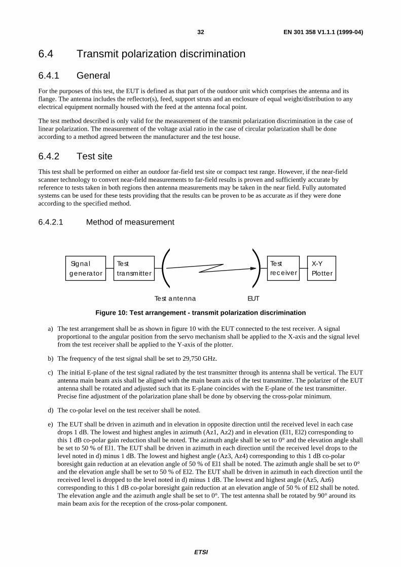
ETSI
EN 301 358 V1.1.1 (1999-04)32
6.4 Transmit polarization discrimination
6.4.1 General
For the purposes of this test, the EUT is defined as that part of the outdoor unit which comprises the antenna and itsflange. The antenna includes the reflector(s), feed, support struts and an enclosure of equal weight/distribution to anyelectrical equipment normally housed with the feed at the antenna focal point.
The test method described is only valid for the measurement of the transmit polarization discrimination in the case oflinear polarization. The measurement of the voltage axial ratio in the case of circular polarization shall be doneaccording to a method agreed between the manufacturer and the test house.
6.4.2 Test site
This test shall be performed on either an outdoor far-field test site or compact test range. However, if the near-fieldscanner technology to convert near-field measurements to far-field results is proven and sufficiently accurate byreference to tests taken in both regions then antenna measurements may be taken in the near field. Fully automatedsystems can be used for these tests providing that the results can be proven to be as accurate as if they were doneaccording to the specified method.
6.4.2.1 Method of measurement
Signalgenerator
Testtransmitter
Testreceiver
X-YPlotter
EUTTest antenna
Figure 10: Test arrangement - transmit polarization discrimination
a) The test arrangement shall be as shown in figure 10 with the EUT connected to the test receiver. A signalproportional to the angular position from the servo mechanism shall be applied to the X-axis and the signal levelfrom the test receiver shall be applied to the Y-axis of the plotter.
b) The frequency of the test signal shall be set to 29,750 GHz.
c) The initial E-plane of the test signal radiated by the test transmitter through its antenna shall be vertical. The EUTantenna main beam axis shall be aligned with the main beam axis of the test transmitter. The polarizer of the EUTantenna shall be rotated and adjusted such that its E-plane coincides with the E-plane of the test transmitter.Precise fine adjustment of the polarization plane shall be done by observing the cross-polar minimum.
d) The co-polar level on the test receiver shall be noted.
e) The EUT shall be driven in azimuth and in elevation in opposite direction until the received level in each casedrops 1 dB. The lowest and highest angles in azimuth (Az1, Az2) and in elevation (El1, El2) corresponding tothis 1 dB co-polar gain reduction shall be noted. The azimuth angle shall be set to 0° and the elevation angle shallbe set to 50 % of El1. The EUT shall be driven in azimuth in each direction until the received level drops to thelevel noted in d) minus 1 dB. The lowest and highest angle (Az3, Az4) corresponding to this 1 dB co-polarboresight gain reduction at an elevation angle of 50 % of El1 shall be noted. The azimuth angle shall be set to 0°and the elevation angle shall be set to 50 % of El2. The EUT shall be driven in azimuth in each direction until thereceived level is dropped to the level noted in d) minus 1 dB. The lowest and highest angle (Az5, Az6)corresponding to this 1 dB co-polar boresight gain reduction at an elevation angle of 50 % of El2 shall be noted.The elevation angle and the azimuth angle shall be set to 0°. The test antenna shall be rotated by 90° around itsmain beam axis for the reception of the cross-polar component.
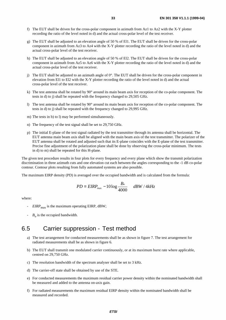
ETSI
EN 301 358 V1.1.1 (1999-04)33
f) The EUT shall be driven for the cross-polar component in azimuth from Az1 to Az2 with the X-Y plotterrecording the ratio of the level noted in d) and the actual cross-polar level of the test receiver.
g) The EUT shall be adjusted to an elevation angle of 50 % of El1. The EUT shall be driven for the cross-polarcomponent in azimuth from Az3 to Az4 with the X-Y plotter recording the ratio of the level noted in d) and theactual cross-polar level of the test receiver.
h) The EUT shall be adjusted to an elevation angle of 50 % of El2. The EUT shall be driven for the cross-polarcomponent in azimuth from Az5 to Az6 with the X-Y plotter recording the ratio of the level noted in d) and theactual cross-polar level of the test receiver.
j) The EUT shall be adjusted to an azimuth angle of 0°. The EUT shall be driven for the cross-polar component inelevation from El1 to El2 with the X-Y plotter recording the ratio of the level noted in d) and the actualcross-polar level of the test receiver.
k) The test antenna shall be rotated by 90° around its main beam axis for reception of the co-polar component. Thetests in d) to j) shall be repeated with the frequency changed to 29,505 GHz.
l) The test antenna shall be rotated by 90° around its main beam axis for reception of the co-polar component. Thetests in d) to j) shall be repeated with the frequency changed to 29,995 GHz.
m) The tests in b) to l) may be performed simultaneously.
n) The frequency of the test signal shall be set to 29,750 GHz.
p) The initial E-plane of the test signal radiated by the test transmitter through its antenna shall be horizontal. TheEUT antenna main beam axis shall be aligned with the main beam axis of the test transmitter. The polarizer of theEUT antenna shall be rotated and adjusted such that its E-plane coincides with the E-plane of the test transmitter.Precise fine adjustment of the polarization plane shall be done by observing the cross-polar minimum. The testsin d) to m) shall be repeated for this H-plane.
The given test procedure results in four plots for every frequency and every plane which show the transmit polarizationdiscrimination in three azimuth cuts and one elevation cut each between the angles corresponding to the -1 dB co-polarcontour. Contour plots resulting from fully automated systems are also possible.
The maximum EIRP density (PD) is averaged over the occupied bandwidth and is calculated from the formula:
kHzdBWB
EIRPPDo
4/4000
log10max −=
where:
- EIRPmax is the maximum operating EIRP, dBW;
- Bo is the occupied bandwidth.
6.5 Carrier suppression - Test methoda) The test arrangement for conducted measurements shall be as shown in figure 7. The test arrangement for
radiated measurements shall be as shown in figure 6.
b) The EUT shall transmit one modulated carrier continuously, or at its maximum burst rate where applicable,centred on 29,750 GHz.
c) The resolution bandwidth of the spectrum analyser shall be set to 3 kHz.
d) The carrier-off state shall be obtained by use of the STE.
e) For conducted measurements the maximum residual carrier power density within the nominated bandwidth shallbe measured and added to the antenna on-axis gain.
f) For radiated measurements the maximum residual EIRP density within the nominated bandwidth shall bemeasured and recorded.
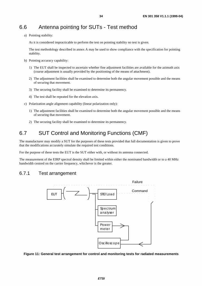
ETSI
EN 301 358 V1.1.1 (1999-04)34
6.6 Antenna pointing for SUTs - Test methoda) Pointing stability:
As it is considered impracticable to perform the test on pointing stability no test is given.
The test methodology described in annex A may be used to show compliance with the specification for pointingstability.
b) Pointing accuracy capability:
1) The EUT shall be inspected to ascertain whether fine adjustment facilities are available for the azimuth axis(coarse adjustment is usually provided by the positioning of the means of attachment).
2) The adjustment facilities shall be examined to determine both the angular movement possible and the meansof securing that movement.
3) The securing facility shall be examined to determine its permanency.
4) The test shall be repeated for the elevation axis.
c) Polarization angle alignment capability (linear polarization only):
1) The adjustment facilities shall be examined to determine both the angular movement possible and the meansof securing that movement.
2) The securing facility shall be examined to determine its permanency.
6.7 SUT Control and Monitoring Functions (CMF)The manufacturer may modify a SUT for the purposes of these tests provided that full documentation is given to provethat the modifications accurately simulate the required test conditions.
For the purpose of these tests the EUT is the SUT either with, or without its antenna connected.
The measurement of the EIRP spectral density shall be limited within either the nominated bandwidth or to a 40 MHzbandwidth centred on the carrier frequency, whichever is the greater.
6.7.1 Test arrangement
STE/Load
Spectrumanalyser
Powermeter
Oscilloscope
EUTCommand
Failure
Figure 11: General test arrangement for control and monitoring tests for radiated measurements
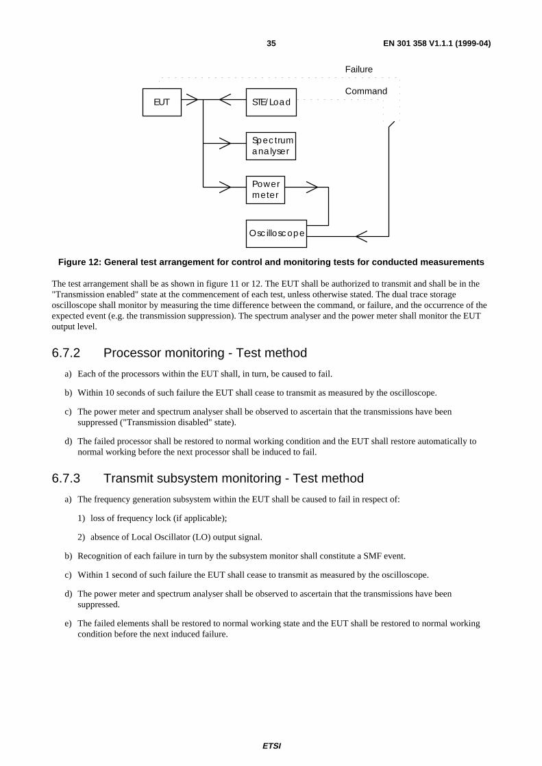
ETSI
EN 301 358 V1.1.1 (1999-04)35
STE/LoadEUT
Spectrumanalyser
Powermeter
Oscilloscope
Command
Failure
Figure 12: General test arrangement for control and monitoring tests for conducted measurements
The test arrangement shall be as shown in figure 11 or 12. The EUT shall be authorized to transmit and shall be in the"Transmission enabled" state at the commencement of each test, unless otherwise stated. The dual trace storageoscilloscope shall monitor by measuring the time difference between the command, or failure, and the occurrence of theexpected event (e.g. the transmission suppression). The spectrum analyser and the power meter shall monitor the EUToutput level.
6.7.2 Processor monitoring - Test method
a) Each of the processors within the EUT shall, in turn, be caused to fail.
b) Within 10 seconds of such failure the EUT shall cease to transmit as measured by the oscilloscope.
c) The power meter and spectrum analyser shall be observed to ascertain that the transmissions have beensuppressed ("Transmission disabled" state).
d) The failed processor shall be restored to normal working condition and the EUT shall restore automatically tonormal working before the next processor shall be induced to fail.
6.7.3 Transmit subsystem monitoring - Test method
a) The frequency generation subsystem within the EUT shall be caused to fail in respect of:
1) loss of frequency lock (if applicable);
2) absence of Local Oscillator (LO) output signal.
b) Recognition of each failure in turn by the subsystem monitor shall constitute a SMF event.
c) Within 1 second of such failure the EUT shall cease to transmit as measured by the oscilloscope.
d) The power meter and spectrum analyser shall be observed to ascertain that the transmissions have beensuppressed.
e) The failed elements shall be restored to normal working state and the EUT shall be restored to normal workingcondition before the next induced failure.
ETSI
EN 301 358 V1.1.1 (1999-04)36
6.7.4 Power-on/Reset - Test method
a) The EUT shall be switched off and the STE shall not transmit the CC.
b) The EUT shall be switched on.
c) The EUT shall not transmit during and after switching-on, and shall enter the "Non valid" state.
The events from a) to c) shall be displayed and verified with the oscilloscope and by measurement of the transmittedsignal. If a manual reset function is implemented the following test shall be performed:
d) The EUT shall be restored to the "Initial phase" state and the STE shall transmit the CC.
e) The EUT shall remain in the "Initial phase" state.
f) The reset function shall be initiated.
g) Within 1 seconds the EUT shall enter the "Non valid" state.
h) The EUT shall be restored to the "Initial phase" state and the STE shall transmit the CC as well as a TxE.
i) The EUT shall enter the "Transmission enabled" state.
j) The reset function shall be initiated.
k) Within 1 seconds the EUT shall enter the "Non valid" state.
The event from e) to k) shall be displayed and verified with the oscilloscope and by measurement of the transmittedsignal.
6.7.5 Control Channel (CC) reception - Test method
Tests shall simulate the following events:
- the CC has never been received by the EUT after power-on;
- the CC is lost by the EUT after reception of a Transmission Enable command;
- the CC is lost by the EUT without reception of a Transmission Enable command;
- the CC is being lost by the EUT and a call is initiated within the Time-Out period T1.
The Time-Out period T1 used in the tests shall be 10 seconds.
a) Case where the CC has never been received by the EUT after power-on:
a1) The EUT shall be switched off and the STE shall not transmit the CC.
a2) The EUT shall be switched on.
a3) The EUT shall remain in the "Non valid" state.
The events from a2) to a3) shall be displayed and verified with the oscilloscope and by measurement of thetransmit signal.
ETSI
EN 301 358 V1.1.1 (1999-04)37
b) Case where the CC is lost by the EUT after reception of a Transmission Enable command:
b1) The EUT shall be switched-on and the STE shall transmit the CC and a TxE.
b2) The EUT shall enter the "Initial phase" state and go, if applicable, to the "Transmission enabled" state.
b3) A transmission request shall be initiated from the EUT.
b4) The STE shall stop transmitting the CC.
b5) Within the period T1 from event b4), the EUT shall enter the "Non valid" state.
The events from b1) to b5) shall be displayed and verified with the oscilloscope and by measurement of thetransmitted signal.
c) Case where the CC is lost by the EUT without reception of a "Transmission enabled" state:
c1) The EUT shall be switched on and the STE shall transmit the CC.
c2) The EUT shall enter the "Initial phase" state.
c3) The STE shall stop transmitting the CC.
c4) The EUT shall enter in the "Non valid" state not later than T1.
c5) A transmission request shall be initiated and the EUT shall remain in the "Non valid" state.
The events from c2) to c5) shall be displayed and verified with the oscilloscope and by measurement of thetransmitted signal.
d) Case where the CC is being lost by the EUT and a call is initiated within the T1 period:
d1) The EUT shall be switched on and the STE shall transmit the CC.
d2) The STE shall stop transmitting the CC.
d3) Within the period T1 from d2), a transmission request shall be initiated from the EUT.
d4) The EUT may transmit but within the T1 period the EUT shall enter the "Non valid" state.
The events from d2) to d4) shall be displayed and verified with the oscilloscope and by measurement of thetransmitted signal.
6.7.6 Network control commands - Test method
The following tests shall be performed in sequence:
- Transmission enable command.
- Transmission disable command received in the "Transmission enabled" state.
- Transmission disable command received in the "Initial phase" state.

ETSI
EN 301 358 V1.1.1 (1999-04)38
a) Transmission enable command:
a1) The EUT shall be switched-on and the STE shall transmit the CC.
a2) The EUT shall enter the "Initial phase" state.
a3) A transmission request shall be initiated from the EUT, the EUT shall remain in the "Initial phase" state.
a4) The STE shall transmit an enable command to the EUT.
a5) A transmission request shall be initiated from the EUT.
a6) The EUT shall enter the "Transmission enabled" state and shall transmit.
The events from a2) to a6) shall be displayed and verified with the oscilloscope and by measurement of thetransmitted signal.
b) Transmission disable command received in the "Transmission enabled" state:
b1) Continue from a6).
b2) The STE shall transmit a disable command to the EUT.
b3) The EUT shall enter the "Transmission disabled" state within 1 second.
b4) A transmission request shall be initiated from the EUT.
b5) The EUT shall remain in the "Transmission disabled" state.
b6) The STE shall transmit an enable command.
b7) The EUT shall enter either the "Transmission enabled" state or the "Initial phase" state.
b8) If the EUT is in the "Transmission enable" state then the test continues with b11).
b9) The STE shall transmit an TxE command.
b10) The EUT shall enter the "Transmission enable" state.
b11) If a transmission request is not active any more then a new transmission request shall be initiated.
b12) The EUT shall transmit.
b13) The EUT transmission shall be terminated.
The events from b2) to b13) shall be displayed and verified with the oscilloscope and by measurement of thetransmitted signal.
ETSI
EN 301 358 V1.1.1 (1999-04)39
c) Transmission disable command received in the "Initial phase" state:
c1) The EUT shall be switched-on and the STE shall transmit the CC.
c2) The EUT shall enter the "Initial phase" state.
c3) The STE shall transmit a disable command to the EUT.
c4) The EUT shall enter the "Transmission disabled" state within 1 second.
c5) A transmission request shall be initiated from the EUT.
c6) The EUT shall remain in the "Transmission disabled" state.
c7) The STE shall transmit an enable command.
c8) The EUT shall enter either the "Transmission enabled" state or the "Initial phase" state.
c9) If the EUT is in the "Transmission enable" state then the test continues with c12).
c10) The STE shall transmit an TxE command.
c11) The EUT shall enter the "Transmission enable" state.
c12) If a transmission request is not active any more then a new transmission request shall be initiated.
c13) The EUT shall transmit.
c14) The EUT transmission shall be terminated.
The events from c2) to c14) shall be displayed and verified with the oscilloscope and by measurement of thetransmitted signal.
6.7.7 Initial burst transmission - Test method
Tests shall be performed to simulate the following events:
- the CC is being received by the EUT;
- the CC has not been received by the EUT since power-on;
a) Case where the CC is being received:
a1) The EUT shall be switched-off and the STE shall transmit the CC.
a2) The EUT shall be switched-on.
a3) The EUT shall not transmit, except the initial bursts.
a4) It shall be verified that the specifications given in 5.6.2 are fulfilled.
The events from a2) to a4) shall be displayed and verified with the oscilloscope and by measurement of thetransmitted signal.
b) Case where the CC has not been received by the EUT since power-on:
b1) The EUT shall be switched-off and the STE shall not transmit the CC.
b2) The EUT shall be switched-on.
b3) The EUT shall not transmit.
The events from b2) to b3) shall be displayed and verified with the oscilloscope and by measurement of thetransmitted signal.
ETSI
EN 301 358 V1.1.1 (1999-04)40
Annex A (informative):Pointing stability methodologyThis test based on a numerical analysis shall be performed in two stages:
- In the first stage the effects of maximum wind speed shall be computed on the outdoor unit using a numericalanalysis method (finite elements method by computer) taking into account the intrinsic properties of thematerials.
- In the second stage the computed loads shall be applied to the structure.
The purpose of the numerical analysis is twofold:
1) to show that the torque and the fields of force applied to the outdoor unit structure under nominated conditions donot reach the breakpoint limit of any element of the structure;
2) to compute equivalent static loads (force and torque) applied to the critical attachment points of the structures,e.g.:
- reflector - mounting legs fixing point;
- reflector - struts;
- LNB - struts.
Numerical analysis and load applications procedure:
1) The air related parameters, namely the kinetic viscosity used to calculate drags at the rims of the structure shallbe calculated with the standard atmospheric environmental conditions (temperature = 293 K,air pressure = 1,013 × 105 Pascal).
2) The computations needed to derive the field of force and torque and the equivalent static stresses shall be carriedout for each of the following variables:
- elevation angle: maximum and minimum;
- wind direction: in steps of 45° around the outdoor unit;
- wind speed: 160 km/h.
3) It shall be verified with the simulated results that break point limits are not exceeded for any self-containedelement.
4) The calculated equivalent static loads shall be applied at any identified critical fixing point of the assembly.
5) While the loads are applied the outdoor unit shall be observed and any distortion noted.
6) The test report shall contain the following information:
- the computation method used;
- description of the test equipment;
- description of the tests performed;
- results of the safety margin test;
- any signs of distortion observed;
- results of the measurements of the deviation of the antenna position;
- component deviation with respect to each other.

ETSI
EN 301 358 V1.1.1 (1999-04)41
BibliographyThe following material, though not specifically referenced in the body of the present document (or not publiclyavailable), gives supporting information.
EN 300 673: "Electromagnetic compatibility and Radio spectrum Matters (ERM); ElectroMagnetic Compatibility(EMC) standard for 4/6 GHz and 11/12/14 GHz Very Small Aperture Terminal (VSAT) equipment and 11/12/13/14GHz Satellite News Gathering (SNG) Transportable Earth Station (TES) equipment".
ETSI
EN 301 358 V1.1.1 (1999-04)42
History
Document history
V1.1.1 July 1998 Public Enquiry PE 9848: 1998-07-31 to 1998-11-27
V1.1.1 January 1999 Vote V 9912: 1999-01-19 to 1999-03-19
V1.1.1 April 1999 Publication
ISBN 2-7437-2958-9Dépôt légal : Avril 1999
Related Documents

![TR 103 166 - V1.1.1 - Satellite Earth Stations and Systems ... · Satellite Earth Stations and Systems ... (transportable station for communication network by ... [i.1] lists general](https://static.cupdf.com/doc/110x72/5b5816bb7f8b9a31668b812a/tr-103-166-v111-satellite-earth-stations-and-systems-satellite-earth.jpg)


