ETSI EN 301 238 V1.3.1 (2001-10) European Standard (Telecommunications series) Digital Enhanced Cordless Telecommunications (DECT); Data Services Profile (DSP); Isochronous data bearer services with roaming mobility (service type D, mobility class 2)

Welcome message from author
This document is posted to help you gain knowledge. Please leave a comment to let me know what you think about it! Share it to your friends and learn new things together.
Transcript
ETSI EN 301 238 V1.3.1 (2001-10)
European Standard (Telecommunications series)
Digital Enhanced Cordless Telecommunications (DECT);Data Services Profile (DSP);
Isochronous data bearer services with roaming mobility(service type D, mobility class 2)

ETSI
ETSI EN 301 238 V1.3.1 (2001-10)2
Reference REN/DECT-A0199
Keywords data, DECT, mobility, profile, radio, roaming
ETSI
650 Route des Lucioles F-06921 Sophia Antipolis Cedex - FRANCE
Tel.: +33 4 92 94 42 00 Fax: +33 4 93 65 47 16
Siret N° 348 623 562 00017 - NAF 742 C
Association à but non lucratif enregistrée à la Sous-Préfecture de Grasse (06) N° 7803/88
Important notice
Individual copies of the present document can be downloaded from: http://www.etsi.org
The present document may be made available in more than one electronic version or in print. In any case of existing or perceived difference in contents between such versions, the reference version is the Portable Document Format (PDF).
In case of dispute, the reference shall be the printing on ETSI printers of the PDF version kept on a specific network drive within ETSI Secretariat.
Users of the present document should be aware that the document may be subject to revision or change of status. Information on the current status of this and other ETSI documents is available at
http://portal.etsi.org/tb/status/status.asp
If you find errors in the present document, send your comment to: [email protected]
Copyright Notification
No part may be reproduced except as authorized by written permission. The copyright and the foregoing restriction extend to reproduction in all media.
© European Telecommunications Standards Institute 2001.
All rights reserved.

ETSI
ETSI EN 301 238 V1.3.1 (2001-10)3
Contents
Intellectual Property Rights ................................................................................................................................6
Foreword.............................................................................................................................................................6
1 Scope ........................................................................................................................................................7
2 References ................................................................................................................................................7
3 Definitions and abbreviations...................................................................................................................8 3.1 Definitions..........................................................................................................................................................8 3.2 Abbreviations .....................................................................................................................................................9
4 Description of services ...........................................................................................................................10 4.1 Reference configuration ...................................................................................................................................10 4.2 Service objectives.............................................................................................................................................10 4.2.1 General........................................................................................................................................................10 4.2.2 32 kbit/s unprotected service ......................................................................................................................11 4.2.3 Unprotected rate adaptation service............................................................................................................11
5 Physical layer (PHL) requirements ........................................................................................................11
6 MAC layer requirements ........................................................................................................................11 6.1 32 kbit/s unprotected service ............................................................................................................................12 6.2 Unprotected rate adaptation service .................................................................................................................12
7 DLC layer requirements .........................................................................................................................17 7.1 C-plane requirements .......................................................................................................................................17 7.2 U-plane requirements .......................................................................................................................................17 7.2.1 32 kbit/s unprotected service ......................................................................................................................17 7.2.2 Unprotected rate adaptation service............................................................................................................18
8 NWK layer requirements........................................................................................................................18 8.1 General .............................................................................................................................................................18 8.2 Requirements....................................................................................................................................................18
9 Management entity requirements ...........................................................................................................19
10 Generic interworking conventions and procedures ................................................................................19 10.1 Bit ordering ......................................................................................................................................................19
Annex A (normative): LU9 - Unprotected Rate Adaptation for V.series Equipment (RAVE) service..............................................................................................................20
A.1 Overview ................................................................................................................................................20 A.1.1 FU9 frame structure..........................................................................................................................................21 A.1.1.1 General frame structure ..............................................................................................................................21 A.1.1.1.1 Mode selection ......................................................................................................................................21 A.1.1.1.2 Mode-dependent fields..........................................................................................................................22 A.1.1.1.3 Length Indicator (LI) and FEC..............................................................................................................22 A.1.1.1.3.1 BCH Coding procedure (normative) ...............................................................................................23 A.1.1.1.3.2 BCH Decoding procedure (Informative) .........................................................................................23 A.1.1.1.4 Indication of Break condition................................................................................................................24 A.1.1.2 FU9 buffering procedures ...........................................................................................................................25 A.1.1.3 Connection handover ..................................................................................................................................25 A.1.1.4 Transmission order .....................................................................................................................................25
A.2 Alignment signal management...............................................................................................................25 A.2.1 General .............................................................................................................................................................25 A.2.2 Procedures ........................................................................................................................................................26
A.3 ITU-T Recommendation V.24 signalling...............................................................................................27 A.3.1 General .............................................................................................................................................................27

ETSI
ETSI EN 301 238 V1.3.1 (2001-10)4
A.3.2 Transmitter procedures.....................................................................................................................................27 A.3.3 Receiver procedures .........................................................................................................................................27
A.4 Rate coding.............................................................................................................................................28 A.4.1 General .............................................................................................................................................................28 A.4.2 Transmitter procedures.....................................................................................................................................29 A.4.3 Receiver procedures .........................................................................................................................................29
A.5 DIC.........................................................................................................................................................29 A.5.1 General .............................................................................................................................................................29 A.5.2 Measurement of phase differences ...................................................................................................................29 A.5.3 Compensation control rules..............................................................................................................................30 A.5.3.1 General........................................................................................................................................................30 A.5.3.2 Optimizing error resilience .........................................................................................................................31 A.5.3.2.1 Procedure for conveying state changes .................................................................................................31 A.5.3.2.2 Procedure for executing positive and negative compensation...............................................................31
A.6 Information field ....................................................................................................................................31 A.6.1 General .............................................................................................................................................................31 A.6.2 User data rates ..................................................................................................................................................32 A.6.2.1 Synchronous mode......................................................................................................................................32 A.6.2.1.1 Information field location and repetition for rates up to 9,6 kbit/s........................................................32 A.6.2.2 Asynchronous mode ...................................................................................................................................32 A.6.2.2.1 Information field location and repetition for rates up to 9,6 kbit/s........................................................33 A.6.3 Information field filling rule.............................................................................................................................34
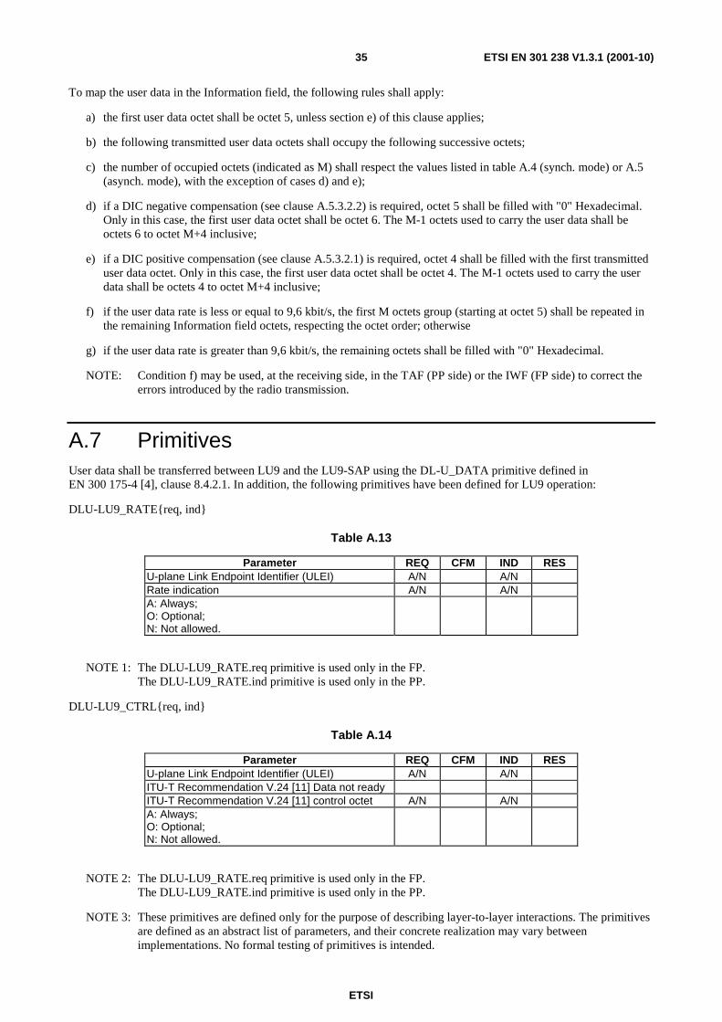
A.7 Primitives ...............................................................................................................................................35
Annex B (normative): Specific interworking conventions................................................................36
B.1 Interworking to connection-oriented bearer services .............................................................................36 B.1.1 Scope ................................................................................................................................................................36 B.1.2 Reference configuration ...................................................................................................................................36 B.1.2.1 PP................................................................................................................................................................37 B.1.2.2 FP................................................................................................................................................................37 B.1.2.3 General configuration .................................................................................................................................38 B.1.3 PP C-plane procedures .....................................................................................................................................38 B.1.4 FP C-plane procedures .....................................................................................................................................38 B.1.5 Network modem interworking service using ITU-T Recommendation V.24 connection ................................39 B.1.5.1 General........................................................................................................................................................39 B.1.5.2 Reference configuration..............................................................................................................................39 B.1.5.3 TAF interworking to ITU-T Recommendation V.24 ..................................................................................39 B.1.5.3.1 General ..................................................................................................................................................39 B.1.5.3.2 ITU-T Recommendation V.24 Interchange circuit handling rules ........................................................40 B.1.5.3.3 Call establishment signalling handling..................................................................................................40 B.1.5.3.4 Data transmission ..................................................................................................................................40 B.1.5.4 DECT FP Interworking procedures ............................................................................................................41 B.1.5.4.1 General ..................................................................................................................................................41 B.1.5.4.2 Call establishment signalling handling..................................................................................................41 B.1.5.4.3 ITU-T Recommendation V.24 Interchange circuit handling rules ........................................................42 B.1.5.4.4 Modem selection ...................................................................................................................................42 B.1.5.4.5 Data transmission ..................................................................................................................................42
B.2 <<IWU-ATTRIBUTES>> coding .........................................................................................................45
Annex C (normative): Service D2; PT Profile Implementation Conformance Statement (ICS) - Physical layer (PHL) .........................................................................48
Annex D (normative): Service D2; FT Profile Implementation Conformance Statement (ICS) - Physical layer (PHL) .........................................................................49
Annex E (normative): Service D2; PT Profile Implementation Conformance Statement (ICS) and PT Protocol Implementation Conformance Statement (PICS) proforma - Medium Access Control (MAC) layer .........................50

ETSI
ETSI EN 301 238 V1.3.1 (2001-10)5
E.1 Service D2; PT Profile Implementation Conformance Statement (ICS) - Medium Access Control (MAC) layer ...........................................................................................................................................51
E.2 Service D2; PT Protocol Implementation Conformance Statement (PICS) proforma - Medium Access Control (MAC) layer..................................................................................................................52
Annex F (normative): Service D2; FT Profile Implementation Conformance Statement (ICS) and Protocol Implementation Conformance Statement (PICS) proforma - Medium Access Control (MAC) layer......................................59
F.1 Service D2; FT Profile Implementation Conformance Statement (ICS) - Medium Access Control (MAC) layer ...........................................................................................................................................60
F.2 Service D2; FT Protocol Implementation Conformance Statement (PICS) proforma - Medium Access Control (MAC) layer..................................................................................................................61
Annex G (normative): Service D2; PT Profile Implementation Conformance Statement (ICS) - Data Link Control (DLC) layer .......................................................65
G.1 C-plane ...................................................................................................................................................65
G.2 U-plane ...................................................................................................................................................65 G.2.1 U-plane 32 kbit/s unprotected service ..............................................................................................................65 G.2.2 U-plane unprotected rate adaptation service ....................................................................................................65
Annex H (normative): Service D2; FT Profile Implementation Conformance Statement (ICS) - Data Link Control (DLC) layer .......................................................66
H.1 C-plane ...................................................................................................................................................66
H.2 U-plane ...................................................................................................................................................66 H.2.1 U-plane 32 kbit/s unprotected service ..............................................................................................................66 H.2.2 U-plane unprotected rate adaptation service ....................................................................................................66
Annex I (informative): Void .................................................................................................................67
Annex J (normative): Service D2; PT profile Requirement List (profile RL) and Protocol Implementation Conformance Statement (PICS) proforma - Network (NWK) layer ...................................................................................................68
J.1 Service D2; PT profile Requirement List (profile RL) - Network (NWK) layer ...................................68
J.2 Service D2; PT Protocol Implementation Conformance Statement (PICS) proforma - Network (NWK) layer...........................................................................................................................................69
Annex K (normative): Service D2; FT profile Requirement List (profile RL) and Protocol Implementation Conformance Statement (PICS) proforma - Network (NWK) layer ...................................................................................................70
K.1 Service D2; FT profile Requirement List (profile RL) - Network (NWK) layer ...................................70
K.2 Service D2; FT Protocol Implementation Conformance Statement (PICS) proforma - Network (NWK) layer...........................................................................................................................................71
Annex L (informative): Bibliography...................................................................................................72
History ..............................................................................................................................................................73

ETSI
ETSI EN 301 238 V1.3.1 (2001-10)6
Intellectual Property Rights IPRs essential or potentially essential to the present document may have been declared to ETSI. The information pertaining to these essential IPRs, if any, is publicly available for ETSI members and non-members, and can be found in ETSI SR 000 314: "Intellectual Property Rights (IPRs); Essential, or potentially Essential, IPRs notified to ETSI in respect of ETSI standards", which is available from the ETSI Secretariat. Latest updates are available on the ETSI Web server (http://www.etsi.org/legal/home.htm).
Pursuant to the ETSI IPR Policy, no investigation, including IPR searches, has been carried out by ETSI. No guarantee can be given as to the existence of other IPRs not referenced in ETSI SR 000 314 (or the updates on the ETSI Web server) which are, or may be, or may become, essential to the present document.
Foreword This European Standard (Telecommunications series) has been produced by ETSI Project Digital Enhanced Cordless Telecommunications (DECT).
National transposition dates
Date of adoption of this EN: 5 October 2001
Date of latest announcement of this EN (doa): 31 January 2002
Date of latest publication of new National Standard or endorsement of this EN (dop/e):
31 July 2002
Date of withdrawal of any conflicting National Standard (dow): 31 July 2002

ETSI
ETSI EN 301 238 V1.3.1 (2001-10)7
1 Scope The present document specifies a profile for Digital Enhanced Cordless Telecommunications (DECT) systems conforming to EN 300 175, parts 1 to 7 ( [1] to [7]). It is part of a family of profiles aimed at the general connection of terminals supporting non-voice services to a fixed infrastructure, private and public.
The type D service, mobility class 2, as described in the ETR 185 [9] supports Isochronous Data Bearer Services (IDBSs) with mobility and is suitable for transparent transfer of isochronous data streams. It is intended for use in private and public roaming applications. Video telephony, video conferencing and secure telephone services (end-to-end encrypted) over external networks can be considered as applications of IDBS.
Phase 1 of the present document defines an unprotected service offering an unrestricted digital 32 kbit/s data bearer service, strongly based on the Generic Access Profile (GAP) (defined in EN 300 444 [8]), and an unprotected single bearer, multi-rate, rate adaptation service to interwork to synchronous ITU-T Recommendations V.series interfaces.
In addition to the above, the current D.2 service supports an asynchronous version of the unprotected single bearer, multi-rate, rate adaptation service to interwork with asynchronous ITU-T Recommendations V.series interfaces.
Further phases of this profile may additionally provide multiple rate, multibearer support and limited error correction capability for services/applications requiring higher rates and high quality isochronous data transmission.
The present document specifies the requirements on the Physical layer (PHL), Medium Access Control (MAC) layer, Data Link Control (DLC) layer and Network (NWK) layer of DECT. The present document also specifies Management Entity (ME) requirements and generic Interworking Conventions (IC).
2 References The following documents contain provisions which, through reference in this text, constitute provisions of the present document.
• References are either specific (identified by date of publication and/or edition number or version number) or non-specific.
• For a specific reference, subsequent revisions do not apply.
• For a non-specific reference, the latest version applies.
[1] ETSI EN 300 175-1: "Digital Enhanced Cordless Telecommunications (DECT); Common Interface (CI); Part 1: Overview".
[2] ETSI EN 300 175-2: "Digital Enhanced Cordless Telecommunications (DECT); Common Interface (CI); Part 2: Physical layer (PHL)".
[3] ETSI EN 300 175-3: "Digital Enhanced Cordless Telecommunications (DECT); Common Interface (CI); Part 3: Medium Access Control (MAC) layer".
[4] ETSI EN 300 175-4: "Digital Enhanced Cordless Telecommunications (DECT); Common Interface (CI); Part 4: Data Link Control (DLC) layer".
[5] ETSI EN 300 175-5: "Digital Enhanced Cordless Telecommunications (DECT); Common Interface (CI); Part 5: Network (NWK) layer".
[6] ETSI EN 300 175-6: "Digital Enhanced Cordless Telecommunications (DECT); Common Interface (CI); Part 6: Identities and addressing".
[7] ETSI EN 300 175-7: "Digital Enhanced Cordless Telecommunications (DECT); Common Interface (CI); Part 7: Security features".
[8] ETSI EN 300 444: "Digital Enhanced Cordless Telecommunications (DECT); Generic Access Profile (GAP)".

ETSI
ETSI EN 301 238 V1.3.1 (2001-10)8
[9] ETSI ETR 185: "Digital Enhanced Cordless Telecommunications (DECT); Data Services Profile (DSP); Profile overview".
[10] ITU-T Recommendation V.110: "Support by an ISDN of data terminal equipments with V-Series type interfaces".
[11] ITU-T Recommendation V.24 (2000): "List of definitions for interchange circuits between data terminal equipment (DTE) and data circuit-terminating equipment (DCE)".
[12] ITU-T Recommendation V.34 (1998): "A modem operating at data signalling rates of up to 33 600 bit/s for use on the general switched telephone network and on leased point-to-point 2-wire telephone-type circuits".
[13] ETSI ETS 300 474-1: "Digital Enhanced Cordless Telecommunications (DECT); Generic Access Profile (GAP); Profile requirement list and profile specific Implementation Conformance Statement (ICS) proforma; Part 1: Portable radio Termination (PT)".
[14] ETSI ETS 300 474-2: "Digital Enhanced Cordless Telecommunications (DECT); Generic Access Profile (GAP); Profile requirement list and profile specific Implementation Conformance Statement (ICS) proforma; Part 2: Fixed radio Termination (FT)".
[15] ETSI EN 300 476-1: "Digital Enhanced Cordless Telecommunications (DECT); Common Interface (CI); Protocol Implementation Conformance Statement (PICS) proforma; Part 1: Network (NWK) layer - Portable radio Termination (PT)".
[16] ETSI ETS 300 476-3: "Digital Enhanced Cordless Telecommunications (DECT); Common Interface (CI); Protocol Implementation Conformance Statement (PICS) proforma; Part 3: Medium Access Control (MAC) layer - Portable radio Termination (PT)".
[17] ETSI ETS 300 476-4: "Digital Enhanced Cordless Telecommunications (DECT); Common Interface (CI); Protocol Implementation Conformance Statement (PICS) proforma; Part 4: Network (NWK) layer - Fixed radio Termination (FT)".
[18] ETSI ETS 300 476-6: "Digital Enhanced Cordless Telecommunications (DECT); Common Interface (CI); Protocol Implementation Conformance Statement (PICS) proforma; Part 6: Medium Access Control (MAC) layer - Fixed radio Termination (FT)".
[19] ITU-T Recommendation R.140: "Definitions of essential technical terms in the field of telegraph transmission".
3 Definitions and abbreviations
3.1 Definitions For the purposes of the present document, the terms and definitions given in EN 300 444 [8] and the following apply:
bearer service: type of telecommunications service that provides the capability for the transmission of signals between user/network interfaces
NOTE 1: For DECT systems, the Air (Radio) interface provides the bearer services between the DECT Fixed radio Termination and the DECT Portable radio Termination.
isochronous: pertaining to a signal or a time-varying phenomenon characterized by significant instants separated by time intervals having a duration theoretically equal to the duration of a unit interval or to an integral multiple of this duration (ITU-T Recommendation R.140)
mobility class 1: closed user groups, for which terminals are pre-registered off-air with one or more specific Fixed Parts (FP), and establishment of service and user parameters is therefore implicit, according to a profile-defined list
mobility class 2: private and public roaming applications for which terminals may move between FPs within a given domain and for which association of service parameters is explicit at the time of service request

ETSI
ETSI EN 301 238 V1.3.1 (2001-10)9
service: set of functions offered to a user by an organization
synchronous: essential characteristics of time-scales or signals such that their corresponding significant instants occur at precisely the same average rate (not in ITU-T Recommendation R.140)
synchronous transmission: transmission using isochronous signals in which the sending and receiving instruments are operating continuously in a constant time difference between corresponding significant instants (ITU-T Recommendation R.140)
3.2 Abbreviations For the purposes of the present document, the following abbreviations apply:
AAL ATM Adaptation Layer ATM Asynchronous Transfer Mode CC Call Control C-plane Control plane CRC Cyclic Redundancy Check Cs higher layer signalling Channel (slow) DCE Data Circuit-terminating Equipment DIC DECT Independent Clocking DLC Data Link Control DSP Data Services Profile DTE Data Terminal Equipment FP Fixed Part FT Fixed radio Termination GAP Generic Access Profile GSM Global System for Mobile communication I higher layer Information channel IC Interworking Conventions ICS Implementation Conformance Statement IDBS Isochronous Data Bearer Service IE Information Element ISDN Integrated Services Digital Network IWF InterWorking Functions IWU InterWorking Unit LA Location Area LCE Link Control Entity LCN Logical Connection Number MAC Medium Access Control ME Management Entity MM Mobility Management MUX MUltipleX NWK NetWorK PHL PHysical Layer PHY PHYsical PICS Protocol Implementation Conformance Statement PP Portable Part ppm parts per million PSTN Public Switched Telephone Network PT Portable radio Termination RAVE Rate Adaption for V.series Equipment SAP Service Access Point SDU Service Data Unit TAF Terminal Adaptation Functions TDMA Time Division Multiple Access ULEI U-plane Link Endpoint Identifier U-plane User plane

ETSI
ETSI EN 301 238 V1.3.1 (2001-10)10
4 Description of services
4.1 Reference configuration The reference configuration for this profile shall be as shown in figure 1.
Application
NWK
DLC
IWF
Service interworkingmanagement
NWK
MAC
PHL
DLC
MAC
PHL
Application
Networkcontrol
Circuitorientednetworkcontrol
C-plane
Application
DLC IWF
MAC
PHL
DLC
MAC
PHL
Application
Networkcontrol
forbearer
servicesNetwork
U-plane
PP FP Network
PP FP Network
Figure 1: Profile reference configuration showing interworking to connection-oriented networks via the C-plane and U-plane
4.2 Service objectives
4.2.1 General
The service objectives for the Control plane (C-plane) are those of mobility class 2, described in clause 6.2.2 of ETR 185 [9].
The service objectives for the User plane (U-plane) are listed in clauses 4.2.2 and 4.2.3.

ETSI
ETSI EN 301 238 V1.3.1 (2001-10)11
4.2.2 32 kbit/s unprotected service
The U-plane service objectives for the unprotected service are detailed in table 1.
Table 1: Service objectives of the 32 kbit/s unprotected service
Transfer mode Circuit mode Transfer capability Unrestricted digital Data structure integrity semi-octet Continuous data rate 32 kbit/s User data protection none User data delay 10 ms Service change and negotiation optional Encryption support mandatory
4.2.3 Unprotected rate adaptation service
The U-plane service objectives for the unprotected rate adaptation service are detailed in table 2.
Table 2: Service objectives of the unprotected rate adaptation service
Transfer mode Circuit mode Transfer capability Unrestricted digital Data structure integrity Octet Continuous data rate By steps of 2,4 kbit/s
up to 28,8 kbit/s; and by steps of 4 kbit/s up to 28,0 kbit/s
User data protection None User data delay 15 ms Service change and negotiation Optional Encryption support Mandatory Network independent clocking Supported In band rate changes Supported ITU-T Recommendation V.24 [11] control signalling Optional Asymmetric rates Supported
5 Physical layer (PHL) requirements The requirements of the GAP, defined in EN 300 444 [8], clause 11 shall apply, with the following exception:
- in clause 11.1, the sentence "To carry the speech information, full slots shall be used" shall be replaced by "Full slots shall be used".
6 MAC layer requirements For both the services, the following shall apply:
a) bit a12 of the Fixed Part Capabilities message (defined in EN 300 175-3 [3], clause 7.2.3.4) shall be set to 1; and
b) the MAC Extended Fixed Part Capabilities message (defined in EN 300 175-3 [3], clause 7.2.3.5) shall be used and bit a44 of Extended capabilities field shall be set to 1.
NOTE: The Extended Fixed Part Capabilities message is broadcast by a FP to indicate the support of the D profile.

ETSI
ETSI EN 301 238 V1.3.1 (2001-10)12
6.1 32 kbit/s unprotected service The requirements of the GAP, defined in EN 300 444 [8], clause 10 shall apply.
6.2 Unprotected rate adaptation service The requirements of GAP, defined in EN 300 444 [8], clause 10 shall apply, with the following additions/variations (a to j):
a) replace clause 10.1 with the following text:
10.1 General
The FT and PT shall support In_normal_delay service as defined in EN 300 175-3 [3], clause 10.8.3.2.
The FT and PT shall support frame format as follows:
- full slot mode defined in EN 300 175-3 [3], clause 4.2.2;
- D-field mapping shall support the D-00 and D32 as defined in EN 300 175-3 [3], clause 6.2.1.1.
The FT and PT shall support A-field mapping A-MAP.
The FT and PT shall understand all A field tail identifications (a0, a1 and a2) in the header field as defined in EN 300 175-3 [3], clauses 6.2.1.2 and 7.1.2.
The FT and PT shall support the following B-field field identifications (a4, a5 and a6) as defined in EN 300 175-3 [3], clause 7.1.4:
- U-type: In, "000"B;
- no B-field, "111" B (shall only be used for dummy bearers).
The FT and PT shall support T-MUX as defined in EN 300 175-3 [3], clause 6.2.2.1.
The FT and PT shall support B-field multiplex E/U MUX type U32a.
The FT and PT shall support scrambling as defined in EN 300 175-3 [3], clause 6.2.4.
The FT and PT shall provide R-CRC generation and checking as defined in EN 300 175-3 [3], clause 6.2.5.2. The FT and PT shall provide X-CRC generation and checking as defined in EN 300 175-3 [3], clauses 6.2.5.3 and 6.2.5.4.
The PT shall support the normal duty cycle idle_locked mode as defined in EN 300 175-3 [3], clauses 11.3 and 4.3.1.
The FT and PT shall support primary scan procedure as defined in EN 300 175-3 [3], clause 11.8.

ETSI
ETSI EN 301 238 V1.3.1 (2001-10)13
b) replace clause 10.2.3 with the following text:
10.2.3 QT - FP capabilities
If the bit a33 in higher layer capabilities (see table 102) is set to value "1", the PT may assume the values as indicated in table 91 to be set to value "1". The FT shall set the respective values to "1".
Table 91: Values used within FP capabilities
MAC message Field within the message Standard values within the MAC message
Normative action/comment
<<FP capabilities>> <QH> 3 <a12> 1 Extended FP info <a17> 1 Full slot <a24> 1 Advanced A-field
set-up
<a28> 1 In normal delay
Higher layer information: the management entity in the FP supplies the MAC layer with a 16-bit SDU via the Management Entity (ME) SAP. At the PT the MAC layer passes the 16-bits out through the ME SAP to the management entity.
For the setting of the higher layer information bits, see clause 13.6.
c) add the following new clause 10.2.5 with the following text:
10.2.5 QT - Extended FP capabilities
The procedure shall be performed as defined in clauses 7.2.3.5 and 7.2.3.1 of EN 300 175-3 [3].
Table 92a: Values used within Extended FP capabilities
MAC message Field within the message Standard values within the MAC message
Normative action/comment
<<Extended FP capabilities>>
<QH> 4 <a44> 1 D profile

ETSI
ETSI EN 301 238 V1.3.1 (2001-10)14
d) replace clause 10.4 with the following text:
10.4 Set-up of advanced connection, A-field advanced bearer set-up
The procedure shall be performed as defined in EN 300 175-3 [3], clauses 10.2.4.2 and 10.5.1.2.
PT FT
ACCESS_REQUEST
BEARER_CONFIRM
WAIT
WAIT
ATTRIBUTES_T
ATTRIBUTES_R
WAIT
WAIT
OTHER
OTHER
MAC-CON.Req
MAC-CON.Cfm
MAC-CON.Ind
::
::
Figure 2: Set-up of advanced connection and bearer

ETSI
ETSI EN 301 238 V1.3.1 (2001-10)15
e) replace clause 10.4.1 with the following text:
10.4.1 MT message
The following fields as defined in EN 300 175-3 [3], clause 7.2.5.3 of in the MAC control (MT) message shall be supported by the PT and the FT.
Table 95: Values used within MT message
MAC message Field within the message Standard values within the MAC message
Normative action/comment
<<MT message>> <MT header> 1 "Advanced connection
control"
<Command> 0 "Access_request" 4 "Bearer_confirm" 5 "Wait" <FMID> All <PMID> All See clause 13.4
Table 95a: Values used within MT message
MAC message Field within the message Standard values within the MAC message
Normative action/comment
<<MT message>> <MT header> 1 "Advanced connection
control"
<Command> 6 "Attributes_T.Req" 7 "Attributes_T.Cfm" <ECN> All <LBN> 15 <up/down/sm/ss> 3 <ser type> 1 <max life> 0 <slot type> 0 <CF> 0 <FMID> All <PMID> All See clause 13.4
f) replace clause 10.5.1 with the following text:
10.5.1 MT message
The following fields as defined in EN 300 175-3 [3], clause 7.2.5.3 in the MAC control (MT) message shall be supported by the PT and the FT.
Table 96: Values used within MT message
MAC message Field within the message Standard values within the MAC message
Normative action/comment
<<MT message>> <MT header> 1 "Advanced connection
control"
<Command> 0 "Release" <spr> 0 <LBN> 15 <PMID> All See clause 13.4

ETSI
ETSI EN 301 238 V1.3.1 (2001-10)16
g) replace clause 10.6 with the following text:
10.6 Bearer handover request
The procedure shall be performed as defined in EN 300 175-3 [3], clauses 10.6.2 and 10.5.1.2.
The procedure is equivalent for intra- and inter-cell handover.
The FT should not release the old bearer within 10 ms after the establishment of the new bearer.
h) replace clause 10.6.1 with the following text:
10.6.1 MT message
The following fields as defined in EN 300 175-3 [3], clause 7.2.5.3 in the MAC control (MT ) message shall be supported by the PT and the FT.
Table 97: Values used within MT message
MAC message Field within the message Standard values within the MAC message
Normative action/comment
<<MT message>> <MT header> 1 "Advanced connection
control"
<Command> 1 "Bearer_handover_ request"
4 "Bearer_confirm" 5 "Wait" <FMID> All <PMID> All See clause 13.4
Table 97a: Values used within MT message
MAC message Field within the message Standard values within the MAC message
Normative action/comment
<<MT message>> <MT header> 1 "Advanced connection
control"
<Command> 6 "Attributes_T.Req" 7 "Attributes_T.Cfm" <ECN> All <LBN> 15 <up/down/sm/ss> 3 <ser type> 1 <max life> 0 <slot type> 0 <CF> 0 <FMID> All <PMID> All See clause 13.4
i) replace clause 10.7 with the following text:
10.7 Connection handover request
The procedure shall be performed as defined in EN 300 175-3 [3], clauses 10.2.4.2 and 10.5.1.2.
The procedure is equivalent for intra- and inter-cell handover.

ETSI
ETSI EN 301 238 V1.3.1 (2001-10)17
j) replace clause 10.7.1 with the following text:
10.7.1 MT message
The following fields as defined in EN 300 175-3 [3], clause 7.2.5.2 in the MAC control (MT) message shall be supported by the PT and the FT.
Table 98: Values used within MT message
MAC message Field within the message Standard values within the MAC message
Normative action/comment
<<MT message>> <MT header> 1 "Advanced connection
control"
<Command> 2 "Connection_handover_ request"
4 "Bearer_confirm" 5 "Wait" <FMID> All <PMID> All See clause 13.4
Table 98a: Values used within MT message
MAC message Field within the message Standard values within the MAC message
Normative action/comment
<<MT message>> <MT header> 1 "Advanced connection
control"
<Command> 6 "Attributes_T.Req" 7 "Attributes_T.Cfm" <ECN> All <LBN> 15 <up/down/sm/ss> 3 <ser type> 1 <max life> 0 <slot type> 0 <CF> 0 <FMID> All <PMID> All See clause 13.4
7 DLC layer requirements The DLC layer shall contain two independent planes of protocol: the C-plane and the U-plane. All internal DECT protocol control shall be handled by the C-plane. All external user data and control shall be handled by the U-plane.
7.1 C-plane requirements The requirements of the GAP, defined in EN 300 444 [8], from clause 9.1 to clause 9.8 inclusive shall apply.
7.2 U-plane requirements
7.2.1 32 kbit/s unprotected service
The requirements of the GAP, defined in EN 300 444 [8], clauses 9.9 and 9.10 shall apply.

ETSI
ETSI EN 301 238 V1.3.1 (2001-10)18
7.2.2 Unprotected rate adaptation service
The requirements described in annex A (LU9 - Unprotected Rate Adaption for V.series Equipment (RAVE) service) of the present document shall apply.
8 NWK layer requirements
8.1 General The NWK layer provisions shall include the following entities:
- Call Control (CC);
- Link Control Entity (LCE);
- Mobility Management (MM).
Portable Part and Fixed Part CC entities shall use circuit switched mode procedures.
Annex B specifies how procedures shall be used.
The MM requirements shall be aligned to the requirements of the GAP, defined in EN 300 444 [8].
The provisions of NWK layer, EN 300 175-5 [5] shall be implemented with respect to the services, procedures, messages and information elements coding listed in annexes B, I and L. The provisions of EN 300 175-6 [6] shall be implemented with respect to the structure and use of identities.
The Extended Higher Layer Fixed Part Information field shall be used with bit a44 set to 1, indicating the support of the D profile.
Support for exchanged attribute procedures shall be mandatory (EN 300 175-5 [5], clause 15.2.3).
The <<RELEASE-REASON>> element shall always be included in the {CC-RELEASE-COM} message.
8.2 Requirements The full requirements of the GAP, defined in EN 300 444 [8] clause 8 shall apply, with the following exceptions and/or additions:
a) both PP and FP shall set the info element <<BASIC SERVICE>> (defined in EN 300 175-5 [5], clause 7.6.4) to"Digital Enhanced Cordless Telecommunications (DECT); Common Interface (CI); Part 5: Network (NWK) layer" value;
b) both PP and FP shall support the information element <<IWU-ATTRIBUTES>> (defined in EN 300 175-5 [5], clause 7.7.21);
c) both PP and FP shall support the information element <<RELEASE-REASON>> (defined in EN 300 175-5 [5], clause 7.6.7).
The specific coding required for the <<IWU-ATTRIBUTES>> information element is defined in clause B.2 of the present document.

ETSI
ETSI EN 301 238 V1.3.1 (2001-10)19
9 Management entity requirements The management entity shall be responsible for maintenance and updating of the logical associations between NWK, DLC, MAC and U-plane entities and shall contain the following procedure groups defined in EN 300 175-4 [4]:
- MAC connection management;
- DLC C-Plane management;
- DLC U-Plane management.
The requirements of mobility class 2 shall be met by the management procedures defined in EN 300 444 [8] with the following exception:
13.6 Broadcast attributes management
RFPs belonging to the same LA shall broadcast the same values of higher layer attributes (see EN 300 175-5 [5], annex F) at any given time.
The PP shall be capable to read and interpret at least the following broadcast attributes codings during locking procedure. In the locked state the PP may assume them as static.
Table 102: Fixed Part Capabilities Broadcast attributes interpretation by the PP (see EN 300 175-5 [5], clause F.1)
Bit number Attribute Value Note a34 Non-voice circuit switched service All a36 Standard authentication required All a37 Standard ciphering supported All a38 Location registration supported All a44 Access rights requests supported All a46 Connection handover supported All
Table 102a: Extended Fixed Part Capabilities Broadcast attributes interpretation by the PP (see EN 300 175-5 [5], clause F.2)
Bit number Attribute Value Note a44 Data service profile D All
10 Generic interworking conventions and procedures
10.1 Bit ordering In order to interwork with other different networks, the data stream in the U-plane shall respect the bit ordering rule described in EN 300 175-3 [3], clause 5.4.5. For simplicity, the same clause is reproduced below.
5.4.5 Order of transmission
Certain primitives exchanged between the MAC layer and the DLC layer may have a SDU containing peer-to-peer messages. The Service Data Unit (SDU) data is arranged as a list of octets or part octets, starting with octet 1. The bits within one octet are numbered from 1 to 8 where the most significant bit has number 8. The MAC layer transmits these octets in ascending order, starting with octet 1. Valid bits within one octet are transmitted in descending order.
The same bit ordering shall be maintained at the interface between the DECT DLC U-plane and the InterWorking Unit (IWU) in the FP. The same bit ordering shall be maintained at the interface between the DECT DLC U-plane and the Terminal Adaptation Functions (TAF) in the PP.

ETSI
ETSI EN 301 238 V1.3.1 (2001-10)20
Annex A (normative): LU9 - Unprotected Rate Adaptation for V.series Equipment (RAVE) service
A.1 Overview The LU9 service provides for the transparent transport of synchronous continuous and asynchronous data at rates suitable for data terminal equipment with V.series interfaces. Specific support for low speed Asynchronous Transfer Mode (ATM) Adaptation Layer-1 (AAL-1) rates is also provided.
The unprotected service offers no error correction of user data and no notification of errors. It therefore offers a simple, easily implemented service for applications where a higher level of bit errors can be accepted. The unprotected service shall use U-DLC transmission class 0.
The protected service is left for further study.
LU9 shall provide mechanisms that offer unprotected reliable transport of synchronous and asynchronous data and reliable transport of LU9 control signalling. Seven main procedures shall be provided:
1) mode selection (synchronous/asynchronous);
2) filtering period indication;
3) transfer of ITU-T Recommendation V.24 [11] signalling;
4) rate indication;
5) DECT Independent Clocking (DIC), synchronous mode only;
6) error-protected Length Indicator, asynchronous mode only;
7) user data transfer.
Each instance of LU9 shall be distinguished by the use of a different Logical Connection Number (LCN).

ETSI
ETSI EN 301 238 V1.3.1 (2001-10)21
A.1.1 FU9 frame structure
A.1.1.1 General frame structure
The FU9 frame is a fixed length fragmentation with two modes of operation: synchronous and asynchronous.
Bit: 8 7 6 5 4 3 2 1 Octet: a
l i gnmen t f i e l d
ITU-T Recommendation
V.24 [11] signalling field
Rate
1
DIC control field or Reserv
ed*
Mode Reserved 2
Reserved or Length Indicator* + FEC* (upper) 3 DIC data field or Length Indicator* + FEC* (lower) 4 Information field 5 Information field N-1 Information field FU9N
NOTE: A "*" indicates asynchronous mode only.
Figure A.1: Frame format type FU9
FU9 is a function of the underlying connection type:
Table A.1: FU9 connection types
Connection type Slot type FU9 IN / normal delay Full slot 40 octets
Other connection types are for further study.
A.1.1.1.1 Mode selection
The FU9 frame supports two modes of operation: synchronous and asynchronous.
The mode indication shall be included during call establishment in the set-up message by setting the IWU service part (octet 4 of the IWU-ATTRIBUTES IE) accordingly.
Also a Mode bit (bit 5 in octet 2) shall indicate whether the synchronous or asynchronous FU9 frame structure is being used.
ETSI
ETSI EN 301 238 V1.3.1 (2001-10)22
Mode (octet 2):
Bit 5 Meaning;
0 Synchronous mode;
1 Asynchronous mode.
The Mode bit shall be protected by the mechanism of filtering periods defined in clause A.2.1 as it cannot change after a call has been established.
During a call the mode of operation can thus be verified by reading the filtered mode bit.
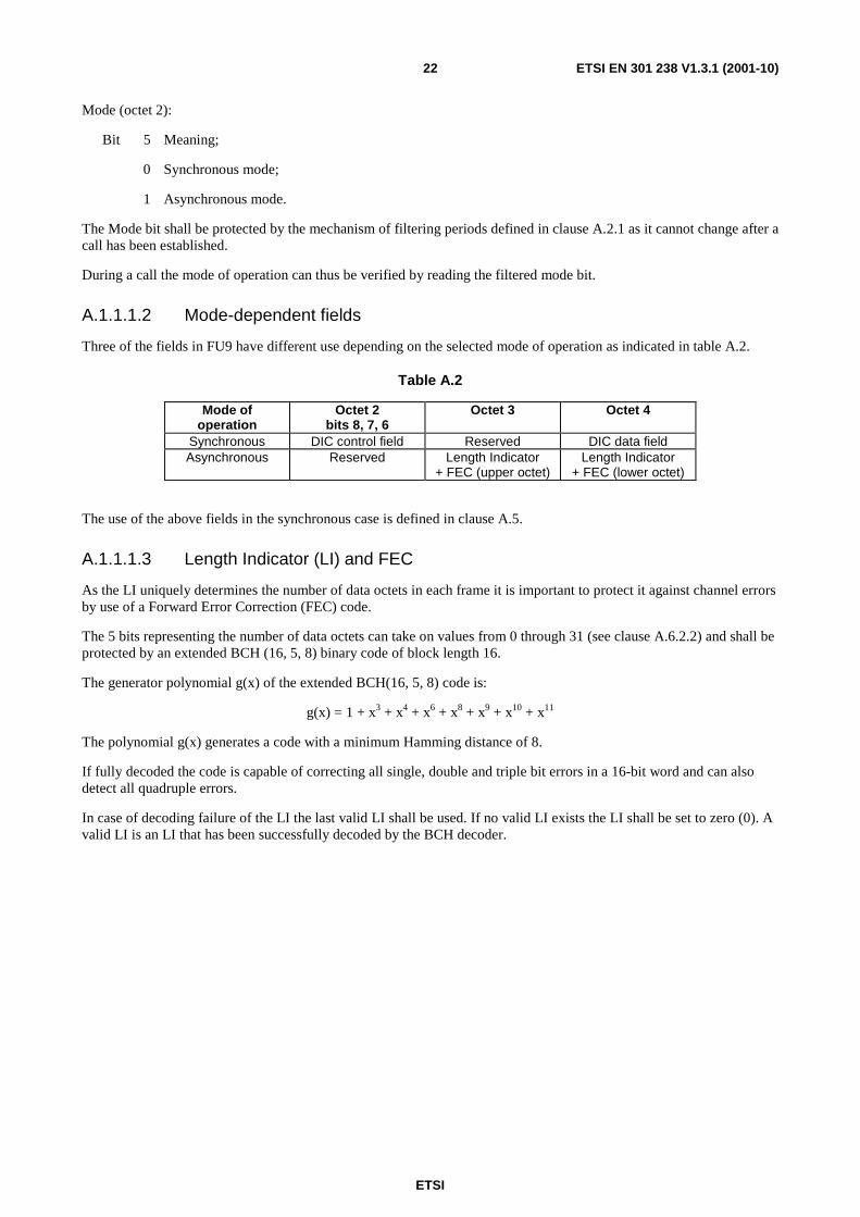
A.1.1.1.2 Mode-dependent fields
Three of the fields in FU9 have different use depending on the selected mode of operation as indicated in table A.2.
Table A.2
Mode of operation
Octet 2 bits 8, 7, 6
Octet 3 Octet 4
Synchronous DIC control field Reserved DIC data field Asynchronous Reserved Length Indicator
+ FEC (upper octet) Length Indicator
+ FEC (lower octet)
The use of the above fields in the synchronous case is defined in clause A.5.
A.1.1.1.3 Length Indicator (LI) and FEC
As the LI uniquely determines the number of data octets in each frame it is important to protect it against channel errors by use of a Forward Error Correction (FEC) code.
The 5 bits representing the number of data octets can take on values from 0 through 31 (see clause A.6.2.2) and shall be protected by an extended BCH (16, 5, 8) binary code of block length 16.
The generator polynomial g(x) of the extended BCH(16, 5, 8) code is:
g(x) = 1 + x3 + x4 + x6 + x8 + x9 + x10 + x11
The polynomial g(x) generates a code with a minimum Hamming distance of 8.
If fully decoded the code is capable of correcting all single, double and triple bit errors in a 16-bit word and can also detect all quadruple errors.
In case of decoding failure of the LI the last valid LI shall be used. If no valid LI exists the LI shall be set to zero (0). A valid LI is an LI that has been successfully decoded by the BCH decoder.

ETSI
ETSI EN 301 238 V1.3.1 (2001-10)23
A.1.1.1.3.1 BCH Coding procedure (normative)
The encoder shall generate and use the following systematic 16-bit codewords.
Table A.3
Information bits (decimal)
Codeword (decimal)
Codeword (hex)
0 0 0x0000 1 2671 0x0A6F 2 5341 0x14DD 3 7858 0x1EB2 4 9174 0x23D6 5 10681 0x29B9 6 14091 0x370B 7 15716 0x3D64 8 18348 0x47AC 9 19907 0x4DC3
10 21361 0x5371 11 22814 0x591E 12 25722 0x647A 13 28181 0x6E15 14 28839 0x70A7 15 31432 0x7AC8 16 34103 0x8537 17 36696 0x8F58 18 37354 0x91EA 19 39813 0x9B85 20 42721 0xA6E1 21 44174 0xAC8E 22 45628 0xB23C 23 47187 0xB853 24 49819 0xC29B 25 51444 0xC8F4 26 54854 0xD646 27 56361 0xDC29 28 57677 0xE14D 29 60194 0xEB22 30 62864 0xF590
31 (see note) 65535 0xFFFF NOTE: Break Indicator, see clause A.1.1.1.4.
All codewords except for the all-zero codeword and the all-ones codeword have Hamming weight 8.
The information bits shall be the 5 most significant bits of each codeword.
NOTE: The above codewords can be stored in a Look-Up-Table (LUT) which can be used for both encoding and decoding.
A.1.1.1.3.2 BCH Decoding procedure (Informative)
A decoding procedure based on the LUT is both simple and fast.
The received 16-bits word (LI + FEC) is checked against all codewords in the LUT by calculating the Hamming distance (number of differing bits). The codeword in the LUT which has the shortest Hamming distance from the received 16-bits word is selected as the decoded codeword. The LI is then extracted as the 5 most significant bits of the decoded codeword.

ETSI
ETSI EN 301 238 V1.3.1 (2001-10)24
Formally the decoding procedure can be described as follows:
Let
R received 16-bits word (LI + FEC);
Ci codeword number i from the LUT, i = 0, 1 … 29;
Si bitwise XOR sum of R and Ci, i = 0, 1 … 29;
Wi Hamming weight of Si (i.e. Hamming distance between R and Ci), i = 0, 1, …, 31.
Then the following decoding procedure is maximum-likelihood:
1) Check the data rate, determine the maximum number of octets/frame (see table in clause A.1.1.1.2) and denote it by M;
2) Extract the 5 information bits from R, these bits form an index (in the range [0, M] + [31]) which is denoted by k;
3) Calculate Sk = R XOR Ck;
4) If Sk = 0 no error has occurred. Extract the 5 information bits (= LI) from Ck. Stop;
5) Calculate Si = R XOR Ci, i = 0, 1, …, M, 31;
6) Calculate Wi (e.g. by a fast table look-up procedure), i = 0, 1 … M, 31;
7) Select the codeword Cs corresponding to the smallest Ws. If more than one codeword yields the same minimum Ws an uncorrectable error has occurred (i.e. decoding failure);
8) If Ws ≤ T, extract the 5 information bits (= LI) from Cs. Stop;
9) If Ws > T an uncorrectable error has occurred (i.e. decoding failure). Stop.
Steps 2, 3 and 4 are used to speed-up the event of no errors which is expected to be the most common situation (if this assumption is not valid, steps 2-4 can be omitted).
The threshold T in steps 8 and 9 can be used to compromise between error correction and error detection as shown in table A.4.
Table A.4
Threshold T Can correct any error of weight up to
Can detect any error of weight up to
0 0 7 1 1 6 2 2 5 3 3 4
The value of the threshold T is chosen by the manufacturer.
The lower the value of T the lower the probability of not detecting an error pattern. On the other hand a low value of T may result in unnecessarily many discarded frames. A suitable compromise could be to set T = 2.
The rate field is used to indicate the maximum number stored in the LI as there is no need to check for codewords corresponding to LI values greater than M.
However the codeword corresponding to the Break Indicator shall always be checked.
A.1.1.1.4 Indication of Break condition
A break condition in the PP or FP is indicated by setting the LI = 31 in the next FU9 frame to be sent on the air interface. The codeword corresponding to LI = 31 is the Break Indicator.

ETSI
ETSI EN 301 238 V1.3.1 (2001-10)25
A.1.1.2 FU9 buffering procedures
The FU9 entity shall be used to provide a data buffering function between the service user and the MAC layer. It shall be required to supply data to the MAC layer (at the transmit side) or accept data from the MAC layer (at the receive side) on demand and with minimum delay.
NOTE: Normal data delivery will be periodic, with frames demanded and delivered at the Time Division Multiple Access (TDMA) frame rate.
Transmit side: on receipt of a MAC_CO_DTR-ind primitive, one complete frame of data shall be submitted to the MAC layer in a MAC_CO_DATA-req primitive.
Receive side: each MAC_CO_DATA-ind primitive shall contain one complete frame of data from the MAC layer.
Data overflow or underflow due to slight clock differences shall be handled by the DIC procedures described in clause A.5.
A.1.1.3 Connection handover
During connection handover, FU9 frames may be sent simultaneously to both the old and the new connections. The receive path is then switched to the new connection as soon as the new connection is indicated to be in the "open" state.
NOTE: Dependent upon the exact implementation of both FT and PT, seamless connection handover should be possible.
A.1.1.4 Transmission order
The physical transmission order shall be controlled by the MAC layer as defined in clause 10.1 of this profile. This MAC layer ordering shall use the octet numbering and bit numbering described in clause 10.
The operations across the DLC layer/MAC layer boundary shall be such that the DLC entity sending a frame can assume this temporal order of the frame, and that the entity receiving the frame can reconstruct it with its assumed temporal order.
In all cases, the order of arrival of the higher layer information shall be preserved, and this shall be identical to the order of transmission.
A.2 Alignment signal management
A.2.1 General For the information carried in the ITU-T Recommendation V.24 [11] signalling field, in the Rate field, in the Mode field, in the DIC control (synch. mode only) and in the DIC data field, a "filtering period" equal to 10 successive FU9 frames is defined.
The filtering period duration is associated to the transmission of a special codeword, called alignment signal, in the bit 7 and bit 8 in octet 1.
The alignment signals shall be continuously transmitted: in this way, the last frame of filtering period numbered N and the first frame of filtering period numbered N+1 shall be consecutive.
To reduce errors due to the hostile nature of the radio channel, the same DIC information shall be maintained constant at least in one filtering period. The ITU-T Recommendation V.24 [11] signalling and Rate information shall be maintained constant at least in two consecutive filtering periods.
Furthermore, changes of values shall be possible only at the beginning of a filtering period. At the receiver side, these variations shall be considered valid only if the receiver is in the locked state.

ETSI
ETSI EN 301 238 V1.3.1 (2001-10)26
For the alignment signal management, the procedures described in clause A.2.2 shall apply.
NOTE: The alignment signal emulates a "square wave" signal. The filtering period is equivalent to the period of the "square wave".
A.2.2 Procedures Transmitter side: The transmitter shall set bit 7 and bit 8 in octet 1 in the FU9 frames constituting the alignment
signal in accordance with table A.5.
Table A.5: Alignment field coding
Frame number bit 7 octet 1
bit 8 octet 1
N 1 1 N+1 1 1 N+2 1 1 N+3 1 1 N+4 1 1 N+5 0 0 N+6 0 0 N+7 0 0 N+8 0 0 N+9 0 0
NOTE: The first frame of the filtering period in table A.5 is frame number N. The last frame of the filtering period in table A.5 is frame number N+9. The possible new value in the ITU-T Recommendation V.24 [11] signalling field, in the Rate field, in the DIC control field and in the DIC data field shall be inserted starting from frame N.
Receiver side: The receiver shall operate in one of two possible states: the "unlocked" state and the "locked" state (see figure A.2).
Unlocked Locked
Event: 3 codewords recognized in atime window of filtering periods
Event: at least 5 codewords not recognizedin a time window of 10 filtering periods
Figure A.2: Receiver side states
In the unlocked state, the receiver shall continuously monitor the status of bit 7 and bit 8 in octet 1 in consecutive received FU9 frames, trying to recognize the alignment signal bit pattern. The receiver shall enter the locked state only if it shall be able to recognize at least 3 alignment signals in a time window of 5 filtering periods (equal to 50 FU9 frames).
In the locked state, the receiver shall continuously monitor the status of bit 7 and bit 8 in consecutive received FU9 frames, trying to recognize the alignment signal bit pattern. The receiver shall enter the unlocked state only if it shall not be able to recognize at least 5 alignment signals in a time window of 10 filtering periods (equal to 100 FU9 frames).
The initial state at the receiver side shall be the unlocked state.

ETSI
ETSI EN 301 238 V1.3.1 (2001-10)27
A.3 ITU-T Recommendation V.24 signalling
A.3.1 General Bits 5 and 6 of octet 1 in FU9 frame shall be used for ITU-T Recommendation V.24 [11] signalling transfer, in the FP ⇒ PP direction only. In the opposite direction (PP ⇒ FP), these bits shall be permanently set to 1.
Bit 8 7 6 5 4 3 2 1 Octet
- CTS DCD
- - -
1
Bit 5 and bit 6 of octet 1 shall be coded as follows:
CTS (octet 1):
Bits 6 Meaning 0 CTS line (circuit 106) OFF 1 CTS line (circuit 106) ON
DCD (octet 1):
Bits 5 Meaning 0 DCD line (circuit 109) OFF 1 DCD line (circuit 109) ON
A.3.2 Transmitter procedures The Interworking Functions (IWF) in the FP shall transfer the status of circuit 106 (CTS) and 109 (DCD) from the V.series interface (see ITU-T Recommendation V.24 [11]) to the TAF in the PP in the octet 1 of an FU9 frame. The individual current status of each circuit shall be maintained for all the FU9 frames of at least two consecutive filtering periods (see clause A.2.1). Individual status transitions of each circuit shall be transferred only from the first frame of a filtering period.
A.3.3 Receiver procedures The TAF in the PP shall determine the status of circuit 106 (CTS) and 109 (DCD) by integration of the relevant bits of FU9 frames belonging to two consecutive filtering periods. The following integration rules shall apply:
a) in a filtering period, the result of the integration shall be the value chosen with majority (at least 6 repetitions on the 10 possible ones). In the event that an equal number (5) of each value is detected the current value shall be maintained;
b) a new status shall be considered valid only if two consecutive filtering periods present the same integration result and the receiver state is "locked" (see clause A.2).

ETSI
ETSI EN 301 238 V1.3.1 (2001-10)28
A.4 Rate coding
A.4.1 General Bits 1 to 4 of octet 1 in FU9 frame shall be used to signal user data rate. This indication is complementary to the user data rate indication already transferred in the C-plane (see clause B.2) which indicates and minimum and maximum rate. This in-band indication can be used for dynamic in-band, in-call rate changes between the indicated C-plane minimum and maximum rates. The in-band rate indication also facilitates the synchronization of the rate indication change with the corresponding change in the number of user data octets in the LU9 information field, see clauses A.4.2, A.4.3 and clause A.6.
Bit 8 7 6 5 4 3 2 1 Octet
- - -
Rate - - -
1
Valid codings of bits 1 to 4 of octet 1 in FU9 frames shall be the following:
If the user data rate resolution (bits 3-4, octet 6) of the <<IWU-ATTRIBUTES>> Information Element (IE) (see clause B.2) indicates "n × 2,4 kbit/s" then:
Rate (octet 1):
Bits 4 3 2 1 Meaning 0 0 0 0 0 kbit/s 0 0 0 1 2,4 kbit/s 0 0 1 0 4,8 kbit/s 0 0 1 1 7,2 kbit/s 0 1 0 0 9,6 kbit/s 0 1 0 1 12 kbit/s 0 1 1 0 14,4 kbit/s 0 1 1 1 16,8 kbit/s 1 0 0 0 19,2 kbit/s 1 0 0 1 21,6 kbit/s 1 0 1 0 24 kbit/s 1 0 1 1 26,4 kbit/s 1 1 0 0 28,8 kbit/s All other values reserved.
If the user data rate resolution (bits 3-4, octet 6) of the <<IWU-ATTRIBUTES>> IE (see clause B.2) indicates "n × 4 kbit/s" then:
Rate (octet 1):
Bits 4 3 2 1 Meaning 0 0 0 0 0 kbit/s 0 0 0 1 4 kbit/s 0 0 1 0 8 kbit/s 0 0 1 1 12 kbit/s 0 1 0 0 16 kbit/s 0 1 0 1 20 kbit/s 0 1 1 0 24 kbit/s 0 1 1 1 28 kbit/s All other values reserved.

ETSI
ETSI EN 301 238 V1.3.1 (2001-10)29
A.4.2 Transmitter procedures The IWF in the FP shall submit a DLU-LU9_RATE.req (containing the new data rate) to the LU9 entity in the FP side. The LU9 entity shall set the Rate field accordingly. The Rate field status shall be maintained for all the FU9 frames of two filtering periods at least (see clause A.2.1). Rate field status changes shall be possible only at the beginning of the same filtering period at which an OFF to ON status transition for the CTS signal takes place (see clause A.3).
The new user data rate shall only take effect (according to the information field specification of clause A.6) from the first frame after the first 2 filtering periods that signalled the change.
A.4.3 Receiver procedures The LU9 entity in the PP shall determine the data rate value by integration of bits 1 to 4 of octet 1 of FU9 frames belonging to two consecutive filtering periods. The following integration rules shall apply:
a) in a filtering period, the result of the integration shall be the value chosen with majority (at least 6 repetitions on the 10 possible ones);
b) the status shall be considered valid only if two consecutive filtering periods present the same integration result and the receiver state is "locked" (see clause A.2).
If condition a) and b) are matched, a DL-LU9_RATE.ind primitive, containing the data rate value, shall be submitted to the upper layer by the LU9 entity in the PP. The information field from the first frame of next filtering period shall be interpreted according to the new user data rate and as specified in clause A.6.
A.5 DIC
A.5.1 General In cases where isochronous data streams at user rates up to and including 28,8 kbit/s are received from a remote data source, the data will usually not be synchronized with the DECT clock. For example, the data may be received through an interworking unit from voice-band modems on the analogue Public Switched Telephone Network (PSTN) where the transmit data from the remote modem is synchronized to the modem clock. The frequency tolerance of such modems is generally 100 parts per million (ppm). Another example is the case where a stream of data octets is received from the Integrated Services Digital Network (ISDN) and the DECT clock is not synchronized with the ISDN clock.
The following method shall be used to enable transfer of those data signals and the corresponding (octet) timing information across the DECT air interface.
A.5.2 Measurement of phase differences The user data is treated as a stream of octets. If the data source provides octet timing, octet integrity is preserved. If the data source does not provide octet timing, received bits are still treated as octets by grouping them together in 8 bit groups.
The phase difference between the following two frequencies will be measured:
- R1 = user data rate in octets/s synchronized with the DECT clock;
- R2 = user data rate in octets/s synchronized with the data source clock (e.g. modem).
Figure A.3 shows the phase diagram for this phase difference (phase (R2) - phase (R1)). Table A.6 shows the related bit coding of the DIC control field.

ETSI
ETSI EN 301 238 V1.3.1 (2001-10)30
0%
20% -20%
40% -40%
Remoteclockrunsfaster(R2 > R1)
Remoteclockrunsslower(R2 < R1)
Mark one octet as dummy.
Transfer an additional octet.
Figure A.3: Phases diagram
Table A.6: Phase differences coding
Displacement Coding DIC control field (octet 2)
bit 8 bit 7 bit 6 0 % 1 0 0
+20 % 0 1 1 +40 % 0 0 0 -40 % 1 1 1 -20 % 0 1 0
A.5.3 Compensation control rules
A.5.3.1 General
The initial state at both transmitting and receiving state is 0 %. Without compensation, the number of conveyed user data octets per frame is N.
Positive compensation:
On transition from +40 % to -40 %, one frame will convey N+1 user data octets.
(Details: see clause A.5.3.2)
Negative compensation:
On transition from -40 % to +40 % one frame will convey N-1 user data octets.
(Details: see clause A.5.3.2)
Hysteresis:
To avoid continuous jitter between neighbouring displacement positions, the displacement code shall be changed only when the measured phase difference is 15 % more or less than the difference indicated by the existing displacement code.
EXAMPLE: Bit combination "011" indicates a phase difference of nominally 20 %. This bit combination will be changed into "000" when the measured phase difference is 35 % or more, and into "100" when the measured phase difference is 5 % or less.

ETSI
ETSI EN 301 238 V1.3.1 (2001-10)31
A.5.3.2 Optimizing error resilience
Transmission errors may hit the DIC control field and may therefore cause malfunctioning of the DIC mechanism. In order to optimize resilience against transmission errors the additional rules described in clauses A.5.3.2.1 and A.5.3.2.2 shall apply.
A.5.3.2.1 Procedure for conveying state changes
Transmitter rules:
Within one filtering period, the DIC control fields of all frames shall indicate the same displacement value. As a consequence state changes can only occur once per filtering period.
Only state changes between adjacent states are allowed.
Receiver rules:
At the end of any received filtering period, the receiver shall examine the contents of the DIC control fields of all frames within that filtering period:
- if at least 6 of the 10 frames included in a filtering period contain the same DIC control field value, that value is accepted. Otherwise the old state value is maintained;
- if the accepted DIC control field value indicates a state change to a non-adjacent state, the state is chosen which is adjacent and located in the appropriate direction.
A.5.3.2.2 Procedure for executing positive and negative compensation
Positive compensation:
The first frame of a filtering period, directly following a filtering period indicating a state change from +40 % to -40 %, shall convey N+1 user data octets, i.e. one octet in the DIC data field, followed by N octets in the user data field.
Negative compensation:
The first frame of a filtering period, directly following a filtering period indicating a state change from -40 % to +40 %, shall convey N-1 user data octets in the user data field.
The value of N is specified in clause A.6.2, table A.7 (synch. mode) or A.8 (asynch. mode) relative to the user data rate.
NOTE 1: The present document is based on a similar (but not identical) mechanism specified in ITU-T Recommendation V.110 [10].
NOTE 2: It is assumed that for DIC management, each frame carries two fields:
- a DIC control field of 3 bits and a DIC data field of 8 bits;
- in the FU9 frame, these are, respectively, octet 2, bits 8-7-6 and octet 4.
A.6 Information field
A.6.1 General Octets 5 to 40 in FU9 frame shall be used for user data transfer.
In asynchronous mode the start and stop bits are removed at the transmitting side and re-inserted at the receiving side.
The rules regarding the in-band signalling of the user data rate, and in particular when the rate changes take effect with respect to the filtering periods, shall apply as specified in clause A.4.

ETSI
ETSI EN 301 238 V1.3.1 (2001-10)32
A.6.2 User data rates
A.6.2.1 Synchronous mode
Different data rates are allowed, from 2,4 kbit/s up to 28,8 kbit/s, by steps of 2,4 kbit/s or 4 kbit/s. The user data rate values and the number of octets required in a FU9 frame are listed in table A.7.
Table A.7: Octets required in the Information field
User data rates (kbit/s) Octets required 0 0
2,4 3 4,8 6 7,2 9 9,6 12 12 15
14,4 18 16,8 21 19,2 24 21,4 27 24 30
26,4 33 28,8 36
4 5 8 10
12 15 16 20 20 25 24 30 28 35
A.6.2.1.1 Information field location and repetition for rates up to 9,6 kbit/s
For rates up to 9,6 kbit/s the information fields shall be repeated to provide improved error resilience.
In synchronous mode the information fields shall always be located at the positions indicated in clause A.6.2.2.1 for asynchronous mode, the only difference being that in synchronous mode there will be valid data also in the fields denoted "Unused".
A.6.2.2 Asynchronous mode
In asynchronous mode the Length Indicator (LI) uniquely determines the number of valid data octets in an FU9 frame.
Since the data octets are stored without start and stop bits, the following number of octets shall be used.
Table A.8: Octets required in the Information field
User data rate (kbit/s)
Average number of octets in each frame
Maximum number of octets in each frame
2,4 2,4 3 4,8 4,8 5 7,2 7,2 8 9,6 9,6 10
12,0 12,0 12 14,4 14,4 15 16,8 16,8 17 19,2 19,2 20 21,6 21,6 22 24,0 24,0 24 26,4 26,4 27 28,8 28,8 29

ETSI
ETSI EN 301 238 V1.3.1 (2001-10)33
When operating in asynchronous mode every frame will not necessarily carry the same number of data octets.
EXAMPLE: for continuous transmission at the peak rate 28,8 kbit/s, 28 octets are transferred in every fifth frame. In the remaining frames, 29 octets are transferred so that the average transfer rate is 28,8 kbit/s.
The above table shows that a maximum of 29 octets shall be transferred in the information field of the FU9 frame in the asynchronous case. A 5-bits LI is thus sufficient.
A.6.2.2.1 Information field location and repetition for rates up to 9,6 kbit/s
For rates up to 9,6 kbit/s the information fields shall be repeated to provide improved error resilience.
Regardless of the number of octets transferred, the information fields shall always be located at the same positions.
The information fields locations at the different rates shall be as shown in the following tables.
At 9,6 kbit/s a maximum of 10 octets is required. The information fields shall be repeated 3 times:
Table A.9: User data rate 9,6 kbit/s
Octet Information field 1.1 to Information field 1.10
5 to 14
Unused 15 Unused 16 Information field 2.1 to Information field 2.10
17 to 26
Unused 27 Unused 28 Information field 3.1 to Information field 3.10
29 to 38
Unused 39 Unused 40
At 7,2 kbit/s a maximum of 8 octets is needed. The information field shall be repeated 4 times:
Table A.10: User data rate 7,2 kbit/s
Octet Information field 1.1 to Information field 1.8
5 to 12
Unused 13 Information field 2.1 to Information field 2.8
14 to 21
Unused 22 Information field 3.1 to Information field 3.8
23 to 30
Unused 31 Information field 4.1 to Information field 4.8
32 to 39
Unused 40

ETSI
ETSI EN 301 238 V1.3.1 (2001-10)34
At the 4,8 kbit/s, a maximum of 5 octets is needed. The information field shall be repeated 6 times:
Table A.11: User data rate 4,8 kbit/s
Octet Information field 1.1 to Information field 1.5
5 to 9
Unused 10 Information field 2.1 to Information field 2.5
11 to 15
Unused 16 Information field 3.1 to Information field 3.5
17 to 21
Unused 22 Information field 4.1 to Information field 4.5
23 to 27
Unused 28 Information field 5.1 to Information field 5.5
29 to 33
Unused 34 Information field 6.1 to Information field 6.5
35 to 39
Unused 40
At the 2,4 kbit/s, a maximum of 3 octets is needed. The information field shall be repeated 12 times:
Table A.12: User data rate 2,4 kbit/s
Octet Information field 1.1 to Information field 1.3
5 to 7
Information field 2.1 to Information field 2.3
8 to 10
Information field 3.1 to Information field 3.3
11 to 13
Information field 4.1 to Information field 4.3
14 to 16
Information field 5.1 to Information field 5.3
17 to 19
Information field 6.1 to Information field 6.3
20 to 22
Information field 7.1 to Information field 7.3
23 to 25
Information field 8.1 to Information field 8.3
26 to 28
Information field 9.1 to Information field 9.3
29 to 31
Information field 10.1 to Information field 10.3
32 to 34
Information field 11.1 to Information field 11.3
35 to 37
Information field 12.1 to Information field 12.3
38 to 40
A.6.3 Information field filling rule At the transmission side, user data shall be submitted to the LU9 transmitting entity with a DL-U_DATA-req (see EN 300 175-4 [4], clause 8.4.2.1). User data shall occupy part or all of the Information field, depending on the user data rate defined in the Rate field (see clause A.4).
ETSI
ETSI EN 301 238 V1.3.1 (2001-10)35
To map the user data in the Information field, the following rules shall apply:
a) the first user data octet shall be octet 5, unless section e) of this clause applies;
b) the following transmitted user data octets shall occupy the following successive octets;
c) the number of occupied octets (indicated as M) shall respect the values listed in table A.4 (synch. mode) or A.5 (asynch. mode), with the exception of cases d) and e);
d) if a DIC negative compensation (see clause A.5.3.2.2) is required, octet 5 shall be filled with "0" Hexadecimal. Only in this case, the first user data octet shall be octet 6. The M-1 octets used to carry the user data shall be octets 6 to octet M+4 inclusive;
e) if a DIC positive compensation (see clause A.5.3.2.1) is required, octet 4 shall be filled with the first transmitted user data octet. Only in this case, the first user data octet shall be octet 4. The M-1 octets used to carry the user data shall be octets 4 to octet M+4 inclusive;
f) if the user data rate is less or equal to 9,6 kbit/s, the first M octets group (starting at octet 5) shall be repeated in the remaining Information field octets, respecting the octet order; otherwise
g) if the user data rate is greater than 9,6 kbit/s, the remaining octets shall be filled with "0" Hexadecimal.
NOTE: Condition f) may be used, at the receiving side, in the TAF (PP side) or the IWF (FP side) to correct the errors introduced by the radio transmission.
A.7 Primitives User data shall be transferred between LU9 and the LU9-SAP using the DL-U_DATA primitive defined in EN 300 175-4 [4], clause 8.4.2.1. In addition, the following primitives have been defined for LU9 operation:
DLU-LU9_RATE{req, ind}
Table A.13
Parameter REQ CFM IND RES U-plane Link Endpoint Identifier (ULEI) A/N A/N Rate indication A/N A/N A: Always; O: Optional; N: Not allowed.
NOTE 1: The DLU-LU9_RATE.req primitive is used only in the FP. The DLU-LU9_RATE.ind primitive is used only in the PP.
DLU-LU9_CTRL{req, ind}
Table A.14
Parameter REQ CFM IND RES U-plane Link Endpoint Identifier (ULEI) A/N A/N ITU-T Recommendation V.24 [11] Data not ready ITU-T Recommendation V.24 [11] control octet A/N A/N A: Always; O: Optional; N: Not allowed.
NOTE 2: The DLU-LU9_RATE.req primitive is used only in the FP. The DLU-LU9_RATE.ind primitive is used only in the PP.
NOTE 3: These primitives are defined only for the purpose of describing layer-to-layer interactions. The primitives are defined as an abstract list of parameters, and their concrete realization may vary between implementations. No formal testing of primitives is intended.

ETSI
ETSI EN 301 238 V1.3.1 (2001-10)36
Annex B (normative): Specific interworking conventions
B.1 Interworking to connection-oriented bearer services
B.1.1 Scope The provisions of this clause shall apply to interworking to public connection-oriented network services. Interworking to ITU-T Recommendations V.series synchronous modems (e.g. ITU-T Recommendation V.34 [12]) and ITU-T Recommendation V.110 [10] are examples of this type of applications. For the purposes of this interworking annex, only full duplex transmissions are to be supported.
The physical implementation of these services and the use of the IWF to other networks (if present) are abstracted from the user. The PP user sees a standardized wireless service which is functionally equivalent to interfacing to an auto-calling/answering Data Circuit-terminating Equipment (DCE) accessing a connection-oriented bearer service (such as modem). In addition the service also provide the security (authentication of PT and encryption, FT activated) as used in the GAP (EN 300 444 [8]), making it suitable for public wireless data services.
The present annex defines the TAF integral to a PP and the IWF integral to a FP which enable the attachment of synchronous serial data applications to a PP and the attachment of connection-oriented serial data transmission network services to an FP. The application may be a software application or a terminal; however the present annex does not mandate the implementation of a specific interface between the PP and the terminal and the FP and the service/network, but specifies the air interface requirements in order to facilitate interoperability between equipment of different origin. Clause B.1.5 of the present annex specifies interworking conventions for Data Terminal Equipment (DTE)-to-PP interfaces based on ITU-T Recommendation V.24 [11], and corresponding conventions for FP IWUs with a nominal internal ITU-T Recommendation V.24 [11] interface.
B.1.2 Reference configuration The reference configuration for U-plane and C-plane operation is shown in figures B.1 and B.2, respectively. The present document refers to Portable Parts (PPs) and Fixed Parts (FPs) which support applications with synchronous serial data transmission capabilities. The TAF is functionally a part of a PP and the IWF is functionally part of FP with an integral synchronous data capability of the DECT D.2 profile.
TAF
Interfaceto DTE
LU9
MAC
PHY
IWF
Connectionorientedbearer service
LU9
MAC
PHY
PP FP
Figure B.1: Profile reference U-plane configuration showing the interworking to a connection-oriented bearer service
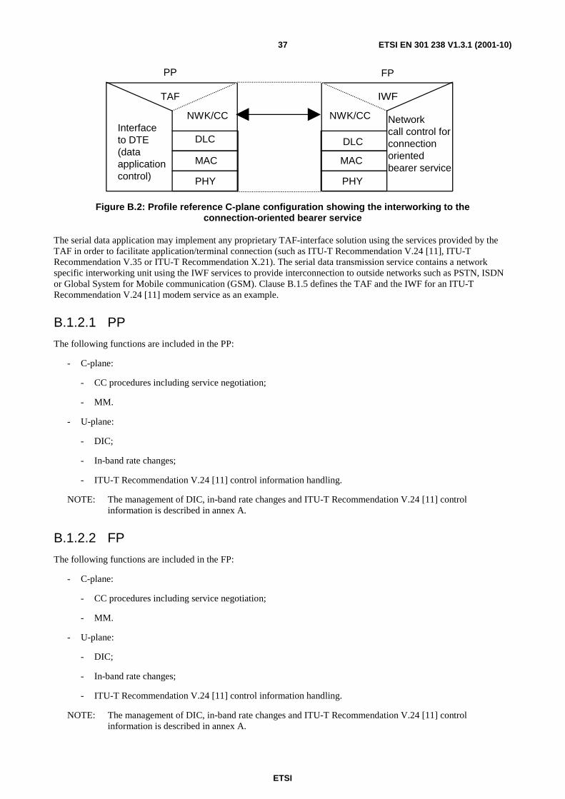
ETSI
ETSI EN 301 238 V1.3.1 (2001-10)37
TAF
Interfaceto DTE(dataapplicationcontrol)
NWK/CC
MAC
PHY
IWF
Networkcall control forconnectionorientedbearer service
MAC
PHY
PP FP
DLC DLC
NWK/CC
Figure B.2: Profile reference C-plane configuration showing the interworking to the connection-oriented bearer service
The serial data application may implement any proprietary TAF-interface solution using the services provided by the TAF in order to facilitate application/terminal connection (such as ITU-T Recommendation V.24 [11], ITU-T Recommendation V.35 or ITU-T Recommendation X.21). The serial data transmission service contains a network specific interworking unit using the IWF services to provide interconnection to outside networks such as PSTN, ISDN or Global System for Mobile communication (GSM). Clause B.1.5 defines the TAF and the IWF for an ITU-T Recommendation V.24 [11] modem service as an example.
B.1.2.1 PP
The following functions are included in the PP:
- C-plane:
- CC procedures including service negotiation;
- MM.
- U-plane:
- DIC;
- In-band rate changes;
- ITU-T Recommendation V.24 [11] control information handling.
NOTE: The management of DIC, in-band rate changes and ITU-T Recommendation V.24 [11] control information is described in annex A.
B.1.2.2 FP
The following functions are included in the FP:
- C-plane:
- CC procedures including service negotiation;
- MM.
- U-plane:
- DIC;
- In-band rate changes;
- ITU-T Recommendation V.24 [11] control information handling.
NOTE: The management of DIC, in-band rate changes and ITU-T Recommendation V.24 [11] control information is described in annex A.
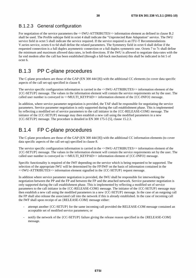
ETSI
ETSI EN 301 238 V1.3.1 (2001-10)38
B.1.2.3 General configuration
For negotiation of the service parameters the <<IWU-ATTRIBUTES>> information element as defined in clause B.2 shall be used. The Profile subtype field in octet 4 shall indicate the "Unprotected Rate Adaptation" service. The IWU service field in octet 5 shall indicate the service required. If the service required is an ITU-T Recommendations V.series service, octets 6 to 6d shall define the related parameters. The Symmetry field in octet 6 shall define if the requested connection is a full duplex asymmetric connection or a full duplex symmetric one. Octets 7 to 7c shall define the minimum and maximum allowed data rates, in both directions. If the IWU is allowed to negotiate data-rates with the far end modem after the call has been established (through a fall-back mechanism) this shall be indicated in bit 5 of octet 6.
B.1.3 PP C-plane procedures The C-plane procedures are those of the GAP (EN 300 444 [8]) with the additional CC elements (to cover data specific aspects of the call set-up) specified in clause 8.
The service specific configuration information is carried in the <<IWU-ATTRIBUTES>> information element of the {CC-SETUP} message. The values in the information element will contain the service requirements set by the user. The called user number is conveyed in <<MULTI_KEYPAD>> information element of the {CC-INFO} message.
In addition, where service parameter negotiation is provided, the TAF shall be responsible for negotiating the service parameters. Service parameter negotiation is only supported during the call establishment phase. This is implemented by reflecting a modified set of service parameters to the call initiator in the {CC-RELEASE-COM} message. The initiator of the {CC-SETUP} message may then establish a new call using the modified parameters in a new {CC-SETUP} message. The procedure is detailed in EN 300 175-5 [5], clause 15.2.3.
B.1.4 FP C-plane procedures The C-plane procedures are those of the GAP (EN 300 444 [8]) with the additional CC information elements (to cover data specific aspects of the call set-up) specified in clause 8.
The service specific configuration information is carried in the <<IWU-ATTRIBUTES>> information element of the {CC-SETUP} message. The values in the information element will contain the service requirements set by the user. The called user number is conveyed in <<MULTI_KEYPAD>> information element of {CC-INFO} message.
Specific functionality is required of the IWF depending on the service which is being requested to be supported. The selection of the appropriate IWU will be determined by the FP/IWF on the basis of information contained in the <<IWU-ATTRIBUTES>> information element signalled in the {CC-SETUP} request message.
In addition where service parameter negotiation is provided, the IWU shall be responsible for interworking the negotiation between the PP and the FP and between the FP and the attached network. Service parameter negotiation is only supported during the call establishment phase. This is implemented by reflecting a modified set of service parameters to the call initiator in the {CC-RELEASE-COM} message. The initiator of the {CC-SETUP} message may then establish a new call using the modified parameters in a new {CC-SETUP} message. In the case of an outgoing call the FP shall also release the associated call into the network if this is already established. In the case of incoming call the IWF shall upon receipt of an {RELEASE-COM} message either:
- attempt another {CC-SETUP} for the same incoming call provided the RELEASE-COM message contained an acceptable set of modified service parameters; or
- notify the network of the {CC-SETUP} failure giving the release reason specified in the {RELEASE-COM} message.

ETSI
ETSI EN 301 238 V1.3.1 (2001-10)39
B.1.5 Network modem interworking service using ITU-T Recommendation V.24 connection
B.1.5.1 General
This clause specifies the interworking of the DECT D.2 services with DTE connected by ITU-T Recommendation V.24 [11] to the PP. It also specifies the functionality of the corresponding IWU in the FP by means of a nominal, reference ITU-T Recommendation V.24 [11] interface to ITU-T-specified DCE. This clause will describe how ITU-T Recommendation V.24 [11] signalling should take place in the TAF and in the IWU.
This clause (and related clauses) do not specify or require the physical realization of ITU-T Recommendation V.24 [11] capable interfaces for equipment claiming support of this interworking annex. Instead they require only the logical realization of equivalent functionality with the aim of DECT air interface interoperability.
B.1.5.2 Reference configuration
The reference configuration is illustrated in figure B.3.
TAF
Interfaceto DTE
LU9
MAC
PHY
IWF
Connectionorientedbearer service
LU9
MAC
PHY
PP FPU-plane
TAF
Interfaceto DTE(dataapplicationcontrol)
NWK/CC
MAC
PHY
IWF
Networkcall control forconnectionorientedbearer serviceMAC
PHY
DLC DLC
NWK/CC
C-planePP FP
DTE DTE
Figure B.3: The reference configuration
B.1.5.3 TAF interworking to ITU-T Recommendation V.24
B.1.5.3.1 General
The ITU-T Recommendation V.24 [11] TAF emulates DCE towards the DTE while interworking the ITU-T Recommendation V.24 [11] status to the CC and DLC primitives. The implementation of the ITU-T Recommendation V.24 [11] interface is not mandatory in the context of this interworking annex, but if the ITU-T Recommendation V.24 [11] interface is implemented physically or logically in the TAF then the provisions of this clause are mandatory. The rules are applicable for both manual and automatic calling.

ETSI
ETSI EN 301 238 V1.3.1 (2001-10)40
B.1.5.3.2 ITU-T Recommendation V.24 Interchange circuit handling rules
The circuit 108/2 (DTR) is required to be in the ON state before the PT/TAF may initiate call establishment (manual or automatic). The circuit 108/2 (DTR) may be used to indicate with ON state to the PT/TAF that the DTE is ready to accept an incoming call.
In the active state, the 108/2 (DTR) transition from ON to OFF state shall cause the TAF to release the connection, after an implementation-specific timeout by issuing an MNCC-RELEASE-req primitive with Release Reason "User Detached".
If 108/2(DTR) is OFF, the TAF shall respond to an incoming call with a MNCC-ALERT-req primitive and shall turn ON circuit 125 (RI). If circuit 108/2(DTR) goes ON in this condition, the TAF shall issue an MNCC-CONNECT-req primitive. It shall be an implementation-specific feature for the TAF to time-out if circuit 108/2 (DTR) does not go ON in this condition, in which case it shall issue an MNCC-RELEASE-req primitive. The TAF may also issue a MNCC-RELEASE-req. primitive independently of the state of circuit 108/2 (DTR), for implementation-specific reasons.
The status change of circuit 107 (DSR) from OFF to ON by PT/TAF shall indicate to the DTE that network call establishment has been successful, that a far-end modem has been detected and that negotiation to establish a carrier has begun.
The status change of 107 (DSR) from ON to OFF by PT/TAF shall indicate to the DTE that the call has been released. Circuit 107 (DSR) shall be turned OFF when the PT/TAF receives MNCC-REJECT-ind primitive.
Circuit 109 (DCD) and 106 (CTS) may be turned ON by the PT/TAF, when a DLU-LU9_CTRL.ind primitive is received reporting these circuits ON during the call establishment, indicating to the DTE the successful establishment of a data carrier to the far-end modem, and the availability of service for end-to-end data transfer. PT/TAF shall transfer the status of circuit 106 (CTS) during the call, as indicated by the DLU-LU9_CTRL.ind primitive, managing momentary unavailability of the fixed network connection due to modem retrains and/or rate renegotiation. PT/TAF shall turn OFF circuit 109 (DCD) if the value of this circuit, as transferred by a DLU-LU9_CTRL.ind primitive, is set to OFF, or if the call is released. PT/TAF shall be responsible for turning circuit 109 (DCD) OFF before circuit 107 (DSR) is turned OFF if it is not already OFF. The status of circuits 105 (RTS) shall not be conveyed across the radio interface.
B.1.5.3.3 Call establishment signalling handling
The TAF shall control call establishment by means of the relevant MNCC primitives, in accordance with the procedures of the GAP. Information about the state of call establishment may be transferred by the TAF to the DTE using ITU-T Recommendation V.24 [11] control signals or locally defined means. Such information is expected to include notification of the MNCC-CALL_PROC-ind, MNCC-ALERT-ind and MNCC-CONNECT-ind primitives. In particular, the TAF shall include means to provide notification to the DTE or the user of the MNCC-CONNECT-ind primitive.
B.1.5.3.4 Data transmission
The data is interworked for LU9 in the PP as described in annex A. For the purposes of this interworking annex the connection over the LU9 service is always a duplex service.
Where octet integrity is available (e.g. 8 bit data async) to and from the PP application the TAF shall maintain this integrity with respect to the receiving and transmitting of user data via LU9.

ETSI
ETSI EN 301 238 V1.3.1 (2001-10)41
B.1.5.4 DECT FP Interworking procedures
B.1.5.4.1 General
FP IWUDECT
C-plane
DECTU-plane
IWF-1 IWF-2 PSTN/ISDN
V.24
rate changes
113
115
Figure B.4: FP IWU reference configuration
This clause specifies the interworking procedures for the IWU of the PSTN/ISDN modem service. This IWU is split into 2 sub-functions called IWF-1 and IWF-2 as shown in figure B.4. IWF-2 is the only function which is attached to the local fixed network. From the perspective of the network this shall function exactly like an ITU-T Recommendations V.series voice-band modem or an ITU-T Recommendation V.110 [10] ISDN termination.
Establishment and release of the PSTN/ISDN calls by IWF-2 shall be controlled on the DECT side by the GAP procedures. The CC primitive parameters have been extended to support the non-voice services standardized herein.
The FP IWU reference configuration defines a logical ITU-T Recommendation V.24 [11] reference point between IWF-1 and IWF-2. This is used to simplify the specification of the interworking of the U-plane data to the modem data since the ITU-T Recommendations V.series modems (including ITU-T Recommendation V.110 [10]) are specified with respect to the ITU-T Recommendation V.24 [11] interface. This shall not in any way restrict the implementation of the FP IWU. In addition, the ITU-T Recommendation V.24 [11] logical interface shall support primitives for transferring in-band rate changes from IWF-2 to IWF-1, due to modem rate-renegotiation procedures.
IWF-1 shall provide the PP TAF transmission clock to IWF-2, as regenerated by means of the DIC functionality, if provided. IWF-1 shall transfer to the PP TAF the clock signal coming from IWF-2 by means of the same functionality.
B.1.5.4.2 Call establishment signalling handling
The modem call establishment is directly signalled to IWF-2 via the DECT network layer primitives and procedures standardized herein using the GAP interworking procedures.
If the selected service is an ITU-T Recommendations V.series voice-band modem the signalling to the local fixed network shall be identical to a standard 3,1 kHz audio call establishment up to the point where the FP CC enters the active state. At this point the behaviour of IWF-2 towards the network shall be in accordance with the ITU-T Recommendations V.series modem selected: the modem configuration parameters (e.g. the type of connection (symmetric or asymmetric), the data rates allowed and the ability of supporting the fall-back mechanism) shall be the ones in the <<IWU-ATTRIBUTES>> IE.
If the selected modem service is an ITU-T Recommendation V.110 [10] ISDN modem the signalling to the local fixed network shall follow the standard ISDN call set-up procedures for the ITU-T Recommendation V.110 [10] service. The ITU-T Recommendation V.110 [10] call set-up parameters for the ISDN call shall use the appropriate parameters from octets 6 to 7c of the <<IWU-ATTRIBUTES>> IE and shall allocate the remaining ITU-T Recommendation V.110 [10] parameters according to the capabilities of IWF-2.

ETSI
ETSI EN 301 238 V1.3.1 (2001-10)42
The "Answer" indication from the local fixed network shall be understood when one or more of the following has been detected:
1) off-hook for the called party has been detected;
2) charging for this call has started;
3) a CONNECT message has been received (e.g. from an ISDN network);
4) the 2 100 Hz modem tone has been detected.
Depending on the attached local fixed network and the called party it may not be possible to detect any of the above. Under such circumstances the FP IWU is permitted to issue a MNCC-RELEASE-req primitive following a timeout period indicating release reason "timer expired".
B.1.5.4.3 ITU-T Recommendation V.24 Interchange circuit handling rules
Circuit 107 (DSR) is required to be in the ON state before the IWF-1 may transmit data on circuit 103 (TXD).
The state of circuit 125 (RI) shall be ignored by IWF-1, since the presence of an incoming call shall be interworked to the DECT network by the IWF-2.The IWF-1 shall transfer the value of circuits 109 (DCD) and circuit 106 (CTS) in DLU9_CONTROL.req primitives using the codings defined in annex A.
Data received via DLU_DATA-req primitives shall be interworked to circuit 103 (TXD). Data received on circuit 104 (RXD) shall be interworked to DL_U_DATA-ind.
B.1.5.4.4 Modem selection
For an outgoing call, the modem type in IWF-2 is selected according to the "modem type" coding of the <<IWU-ATTRIBUTES>> parameter. If this value is not supported by IWF-2, the supported service negotiation procedures shall be invoked by the IWU. If no acceptable modem can be negotiated, the call is rejected with an MNCC-RELEASE-COM-req primitive with release reason (hex) 05 "Incompatible service".
For an incoming call, a locally determined value of the modem type shall be used by the IWU in the MNCC-SETUP-req primitive. The corresponding IWU service and setting parameters shall be indicated in the transmitted <<IWU-ATTRIBUTES>> IE. A PP-initiated peer attribute negotiation (EN 300 175-5 [5], clause 15.2.5) may be used to modify this value, otherwise the IWF-2 may locally determine a new value after it has received the MNCC-CONNECT-ind primitive and has consequently responded to the incoming call and has agreed the modem type to be used. It shall then communicate this in an MNCC-CONNECT_ACK-req primitive.
B.1.5.4.5 Data transmission
The data is interworked for LU9 in the FP as described in annex A. For the purposes of this interworking annex the connection over the LU9 service is always a duplex service.
Where octet integrity is available (e.g. 8 bit data async) to and from the DECT local network the IWF shall maintain this integrity with respect to the receiving and transmitting of user data via LU9.

ETSI
ETSI EN 301 238 V1.3.1 (2001-10)43
Localcalling procedure CC-SETUP(no cpn)
CC-SETUP-ACK
CC-INFO (cpn)
CC-ALERTING (opt)
Call setup
(off hook)
Dialling
Ringing
AnswerCC-CONNECT
107 on
106,109 on
LU9 106,109 on
DLU-LU9_CTRLModemsetup
106,109 on
Datatransfer
Modem startsrate reneg.106 off
DLU-LU9_CTRL
LU9
106 off106 off
Modem endsrate reneg.
106 on
DLU-LU9_CTRL
DLU-LU9_RATELU9
LU9106 on
106 on
rate
Localrelease procedure CC-RELEASE
CC-RELEASE-COM
Release
(Off hook)
107 off
DTE PT/TAF FT/IWF-1 FT/IWF-2DECT local
network
Figure B.5: PP originated call

ETSI
ETSI EN 301 238 V1.3.1 (2001-10)44
Localanswer procedure
CC-SETUP
CC-ALERTING (opt)
Call setup
(off hook)
Ringing
Answer
CC-CONNECT
107 on
106,109 on
LU9 106,109 on
DLU-LU9_CTRLModemsetup
106,109 on
Datatransfer
Localrelease procedure CC-RELEASE
CC-RELEASE-COM
Release
(Off hook)
107 off
DTE PT/TAF FT/IWF-1 FT/IWF-2DECT local
network
CC-CONNECT-ACK
Figure B.6: PP terminated call

ETSI
ETSI EN 301 238 V1.3.1 (2001-10)45
B.2 <<IWU-ATTRIBUTES>> coding Bit: 8 7 6 5 4 3 2 1 Octet
0 <<IWU-ATTRIBUTES>> 1 Length of contents (L) 2 1 Coding
standard Profile 3
1 Negotiation Indicator Profile subtype 4 0/1 IWU service 5 1 Symmetry Fbk Rate Res. Spare 6 0/1 Min user data rate Tx 7 0/1 Max user data rate Tx 7a 0/1 Min user data rate Rx 7b 1 Max user data rate Rx 7c
Figure B.7: IWU-ATTRIBUTES information element
Coding standard (octet 3):
Bits 7 6 Meaning 0 1 Profile defined coding
Profile (octet 3):
Bits 5 4 3 2 1 Meaning 0 0 0 1 0 D data profile
Negotiation indicator (octet 4):
Bits 7 6 5 Meaning These bits are defined as specified EN 300 175-5 [5], clause 7.7.21 Interworking Unit Attributes when the coding
standard (octet 3) indicates "Profile defined coding".
Profile subtype (octet 4):
Bits 4 3 2 1 Meaning 0 0 0 0 32 kbit/s unprotected 0 0 0 1 unprotected rate adaptation synchronous 0 0 1 0 unprotected rate adaptation asynchronous All other values reserved.

ETSI
ETSI EN 301 238 V1.3.1 (2001-10)46
IWU service (octet 5):
Bits 7 6 5 4 3 2 1 Meaning 0 0 0 0 0 0 0 Unspecified V.series voice-band modem 0 0 0 0 0 0 1 ITU-T Recommendation V.21 0 0 0 0 0 1 0 ITU-T Recommendation V.22 0 0 0 0 0 1 1 ITU-T Recommendation V.22bis 0 0 0 0 1 0 0 ITU-T Recommendation V.23 0 0 0 0 1 0 1 ITU-T Recommendation V.26bis 0 0 0 0 1 1 0 ITU-T Recommendation V.26ter 0 0 0 0 1 1 1 ITU-T Recommendation V.27 0 0 0 1 0 0 0 ITU-T Recommendation V.27ter 0 0 0 1 0 0 1 ITU-T Recommendation V.32 0 0 0 1 0 1 0 ITU-T Recommendation V.32 0 0 0 1 0 1 1 ITU-T Recommendation V.34 [12] 0 0 0 1 1 0 0 ITU-T Recommendation V.110 [10] 0 0 0 1 1 0 1 ITU-T Recommendation V.120 0 0 0 1 1 1 0 ITU-T Recommendation V.24 [11] 0 0 0 1 1 1 1 32 kbit/s unprotected 0 0 1 1 0 0 0 ITU-T Recommendation H.324 via 32 kbit/s 0 0 1 1 0 0 1 ATM AAL-1 1 1 1 1 1 1 1 Escape All other values reserved.
Symmetry (octet 6):
Bits 7 6 Meaning 0 0 Asymmetric, full duplex 0 1 Symmetric, full duplex All other values reserved.
Fbk (octet 6):
Bits 5 Meaning 0 Bit rate fall back supported 1 Bit rate fall back not supported
Rate Resolution (octet 6):
Bits 4 3 Meaning 0 0 n × 2,4 kbit/s 0 1 n × 4 kbit/s All other values reserved.
NOTE 1: For support of the 32 kbit/s unprotected service the rate resolution bits are not used and shall be ignored by both sending and receiving side.

ETSI
ETSI EN 301 238 V1.3.1 (2001-10)47
Min user data rate Tx (octet 7):
If the user data rate resolution in octet 6 (bits 3-4) indicate "n × 2,4 kbit/s" then:
Bits 7 6 5 4 3 2 1 Meaning 0 0 0 0 0 0 0 0 kbit/s 0 0 0 0 0 0 1 2,4 kbit/s 0 0 0 0 0 1 0 4,8 kbit/s 0 0 0 0 0 1 1 7,2 kbit/s 0 0 0 0 1 0 0 9,6 kbit/s 0 0 0 0 1 0 1 12 kbit/s 0 0 0 0 1 1 0 14,4 kbit/s 0 0 0 0 1 1 1 16,8 kbit/s 0 0 0 1 0 0 0 19,2 kbit/s 0 0 0 1 0 0 1 21,6 kbit/s 0 0 0 1 0 1 0 24 kbit/s 0 0 0 1 0 1 1 26,4 kbit/s 0 0 0 1 1 0 0 28,8 kbit/s All other values reserved.
If the user data rate resolution in octet 6 (bits 3-4) indicate "n × 4 kbit/s" then:
Bits 7 6 5 4 3 2 1 Meaning 0 0 0 0 0 0 0 0 kbit/s 0 0 0 0 0 0 1 4 kbit/s 0 0 0 0 0 1 0 8 kbit/s 0 0 0 0 0 1 1 12 kbit/s 0 0 0 0 1 0 0 16 kbit/s 0 0 0 0 1 0 1 20 kbit/s 0 0 0 0 1 1 0 24 kbit/s 0 0 0 0 1 1 1 28 kbit/s All other values reserved.
NOTE 2: For support of the 32 kbit/s unprotected service the min user data rate Tx bits are not used and shall be ignored by both sending and receiving side.
Max user data rate Tx (octet 7a) (optional):
This octet is optional. If omitted, the max user data rate Tx shall be interpreted as equal to the rate indicated by octet 7 and octets 7b and 7c shall not be included.
Bits 7 6 5 4 3 2 1 Meaning The coding of these bits is identical to the coding of bits 1 to 7 of octet 7.
Min user data rate Rx (octet 7b) (optional):
This octet is optional. If omitted, the min user data rate Rx shall be interpreted as equal to the rate indicated by octet 7 and octet 7c shall not be included.
Bits 7 6 5 4 3 2 1 Meaning The coding of these bits is identical to the coding of bits 1 to 7 of octet 7.
Max user data rate Rx (octet 7c) (optional):
This octet is optional. If omitted the max user data rate Rx shall be interpreted as equal to the rate indicated by octet 7b.
Bits 7 6 5 4 3 2 1 Meaning The coding of these bits is identical to the coding of bits 1 to 7 of octet 7.

ETSI
ETSI EN 301 238 V1.3.1 (2001-10)48
Annex C (normative): Service D2; PT Profile Implementation Conformance Statement (ICS) - Physical layer (PHL) For all the services, the requirements indicated in ETS 300 474-1 [13], clause A.5 shall apply.

ETSI
ETSI EN 301 238 V1.3.1 (2001-10)49
Annex D (normative): Service D2; FT Profile Implementation Conformance Statement (ICS) - Physical layer (PHL) For all the services, the requirements indicated in ETS 300 474-2 [14], clause A.5 shall apply.

ETSI
ETSI EN 301 238 V1.3.1 (2001-10)50
Annex E (normative): Service D2; PT Profile Implementation Conformance Statement (ICS) and PT Protocol Implementation Conformance Statement (PICS) proforma - Medium Access Control (MAC) layer Notwithstanding the provisions of the copyright clause related to the text of the present document, ETSI grants that users of the present document may freely reproduce the PICS proforma in this annex so that it can be used for its intended purposes and may further publish the completed PICS.
Profile status column
The standardized symbols for the status column are as follows:
m or M mandatory - the capability is required to be supported;
o or O optional - the capability may be supported or not;
n/a or N/A not applicable - in the given context, it is impossible to use the capability;
x or X prohibited (excluded) - there is a requirement not to use this capability in the given context;
o.i or O.i qualified optional - for mutually exclusive or selectable options from a set. "i" is an integer which identifies a unique group of related optional items and the logic of their selection which is defined immediately following the table;
ci or Ci conditional - the requirement on the capability ("m", "o", "x" or "n/a") depends on the support of other optional or conditional items. "i" is an integer identifying a unique conditional status expression which is defined immediately following the table or which is defined in the general condition table below;
i or I out-of-scope - this capability is outside the scope of the given specification, and hence irrelevant and not subject to conformance testing. This status is in particular applicable for data fields which are reserved for future use. The structure of such fields has to be supported, but the value is undefined and thus to be ignored.
If appropriate, a "C" followed by an integer is placed in the status column, providing a reference to a conditional status expression defined elsewhere in the PICS proforma. The following conditions are applicable throughout the entire document.
Condition identifier Condition definition C1 IF "32 kbit/s unprotected service" supported THEN m ELSE i C2 IF "unprotected rate adaptation service asynchronous or synchronous" supported
THEN m ELSE I

ETSI
ETSI EN 301 238 V1.3.1 (2001-10)51
E.1 Service D2; PT Profile Implementation Conformance Statement (ICS) - Medium Access Control (MAC) layer
The requirements indicated in ETS 300 474-1, clause A.4 and the requirements indicated in ETS 300 476-3 shall apply, except for the modifications and/or additions listed below:
Table E.1: ETS 300 474-1, Table A.103
Item Connection oriented control services Profile reference Profile status 1 Basic connections EN 300 444, clause 5.2 C1 2 Advanced symmetric connections EN 300 175-3,
clause 5.6.2.1 C2
Table E.2: ETS 300 474-1, Table A.104
Item Connection services Profile reference Profile status 1 Connection set-up (Basic connections) EN 300 444, clause 5.2 C1 3 Connection data transfer (Basic connections) EN 300 444, clause 5.2 C1 4 Connection handover (intra-cell, inter-cell) EN 300 444, clause 5.2 C1 5 Connection release (Basic connections) EN 300 444, clause 5.2 C1
Table E.3: ETS 300 474-1, Table A.105
Item Symmetric connection oriented services Profile reference Profile status 1 Type 1 IN_minimum_delay (General) EN 300 444,
clauses 5.2, 10.1 C1
2 Type 2 IN_normal_delay EN 300 175-3, clause 5.6.2.1
C2
Table E.4: ETS 300 474-1, Table A.115
Item Name of procedure Profile reference Profile status 1 Basic set-up, single bearer basic connection of known service
(Set-up of basic connection, basic bearer set-up (A-field)) EN 300 444, clause 10.4
C1
2 Normal set-up, single bearer duplex connection known service EN 300 175-3, clause 10.2.4.2
C2
Table E.5: ETS 300 474-1, Table A.116
Item Name of procedure Profile reference Profile status 1 Basic bearer set-up EN 300 444,
clause 10.4 C1
Table E.6: ETS 300 474-1, Table A.129: MAC control (MT) messages (sending P to F)
Item MAC control (MT) messages Profile reference Profile status 1 Basic connection control EN 300 444,
clause 10.4 C1
3 Advanced connection control EN 300 175-3, clause 7.2.5.1
C2
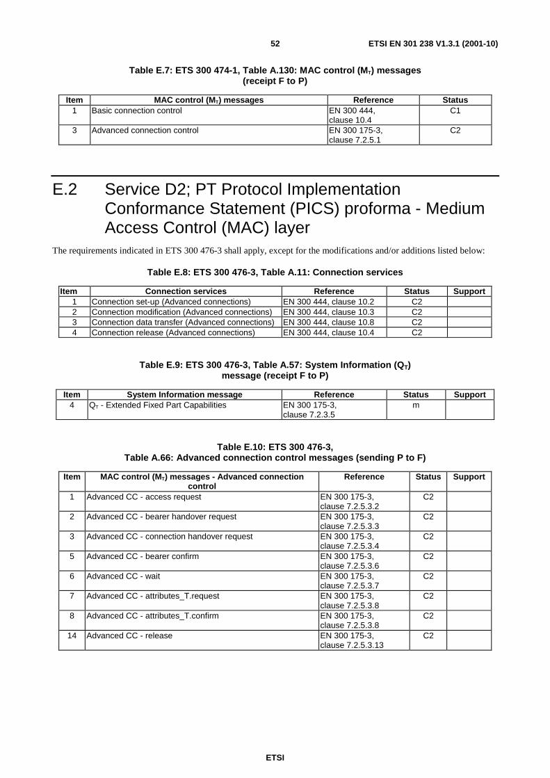
ETSI
ETSI EN 301 238 V1.3.1 (2001-10)52
Table E.7: ETS 300 474-1, Table A.130: MAC control (MT) messages (receipt F to P)
Item MAC control (MT) messages Reference Status 1 Basic connection control EN 300 444,
clause 10.4 C1
3 Advanced connection control EN 300 175-3, clause 7.2.5.1
C2
E.2 Service D2; PT Protocol Implementation Conformance Statement (PICS) proforma - Medium Access Control (MAC) layer
The requirements indicated in ETS 300 476-3 shall apply, except for the modifications and/or additions listed below:
Table E.8: ETS 300 476-3, Table A.11: Connection services
Item Connection services Reference Status Support 1 Connection set-up (Advanced connections) EN 300 444, clause 10.2 C2 2 Connection modification (Advanced connections) EN 300 444, clause 10.3 C2 3 Connection data transfer (Advanced connections) EN 300 444, clause 10.8 C2 4 Connection release (Advanced connections) EN 300 444, clause 10.4 C2
Table E.9: ETS 300 476-3, Table A.57: System Information (QT) message (receipt F to P)
Item System Information message Reference Status Support 4 QT - Extended Fixed Part Capabilities EN 300 175-3,
clause 7.2.3.5 m
Table E.10: ETS 300 476-3, Table A.66: Advanced connection control messages (sending P to F)
Item MAC control (MT) messages - Advanced connection control
Reference Status Support
1 Advanced CC - access request EN 300 175-3, clause 7.2.5.3.2
C2
2 Advanced CC - bearer handover request EN 300 175-3, clause 7.2.5.3.3
C2
3 Advanced CC - connection handover request EN 300 175-3, clause 7.2.5.3.4
C2
5 Advanced CC - bearer confirm EN 300 175-3, clause 7.2.5.3.6
C2
6 Advanced CC - wait EN 300 175-3, clause 7.2.5.3.7
C2
7 Advanced CC - attributes_T.request EN 300 175-3, clause 7.2.5.3.8
C2
8 Advanced CC - attributes_T.confirm EN 300 175-3, clause 7.2.5.3.8
C2
14 Advanced CC - release EN 300 175-3, clause 7.2.5.3.13
C2

ETSI
ETSI EN 301 238 V1.3.1 (2001-10)53
Table E.11: ETS 300 476-3, Table A.67: Advanced connection control messages (receipt F to P)
Item MAC control (MT) messages - Advanced connection control
Reference Status Support
1 Advanced CC - access request EN 300 175-3, clause 7.2.5.3.2
C2
2 Advanced CC - bearer handover request EN 300 175-3, clause 7.2.5.3.3
x
3 Advanced CC - connection handover request EN 300 175-3, clause 7.2.5.3.4
C2
5 Advanced CC - bearer confirm EN 300 175-3, clause 7.2.5.3.6
C2
6 Advanced CC - wait EN 300 175-3, clause 7.2.5.3.7
C2
7 Advanced CC - attributes_T.request EN 300 175-3, clause 7.2.5.3.8
C2
8 Advanced CC - attributes_T.confirm EN 300 175-3, clause 7.2.5.3.8
C2
14 Advanced CC - release EN 300 175-3, clause 7.2.5.3.13
C2
Table E.12: ETS 300 476-3, Table A.130: Advanced CC - access request (sending P to F)
Item Advanced CC - access request
Reference Status Support Value allowed
Value supported
1 MT header EN 300 175-3, clause 7.2.5.3.2
C2 "0001"B
2 Command EN 300 175-3, clause 7.2.5.3.2
C2 "0000"B
3 FMID EN 300 175-3, clause 7.2.5.3.2
C2 12 bits value
4 PMID EN 300 175-3, clause 7.2.5.3.2
C2 20 bits value
Table E.13: ETS 300 476-3, Table A. 131: Advanced CC - access request (receipt F to P)
Item Advanced CC - access request
Reference Status Support Value allowed
Value supported
1 MT header EN 300 175-3, clause 7.2.5.3.2
C2 "0001"B
2 Command EN 300 175-3, clause 7.2.5.3.2
C2 "0000"B
3 FMID EN 300 175-3, clause 7.2.5.3.2
C2 12 bits value
4 PMID EN 300 175-3, clause 7.2.5.3.2
C2 20 bits value

ETSI
ETSI EN 301 238 V1.3.1 (2001-10)54
Table E.14: ETS 300 476-3, Table A.132: Advanced CC - bearer handover request (sending P to F)
Item Advanced CC - bearer handover request
Reference Status Support Value allowed
Value supported
1 MT header EN 300 175-3, clause 7.2.5.3.3
C2 "0001"B
2 Command EN 300 175-3, clause 7.2.5.3.3
C2 "0001"B
3 FMID EN 300 175-3, clause 7.2.5.3.3
C2 12 bits value
4 PMID EN 300 175-3, clause 7.2.5.3.3
C2 20 bits value
Table E.15: ETS 300 476-3, Table A.133: Advanced CC - connection handover request (sending P to F)
Item Advanced CC - connection handover
request
Reference Status Support Value allowed
Value supported
1 MT header EN 300 175-3, clause 7.2.5.3.4
C2 "0001"B
2 Command EN 300 175-3, clause 7.2.5.3.4
C2 "0010"B
3 FMID EN 300 175-3, clause 7.2.5.3.4
C2 12 bits value
4 PMID EN 300 175-3, clause 7.2.5.3.4
C2 20 bits value
Table E.16: ETS 300 476-3, Table A.134: Advanced CC - connection handover request (receipt F to P)
Item Advanced CC - connection handover
request
Reference Status Support Value allowed
Value supported
1 MT header EN 300 175-3, clause 7.2.5.3.4
C2 "0001"B
2 Command EN 300 175-3, clause 7.2.5.3.4
C2 "0010"B
3 FMID EN 300 175-3, clause 7.2.5.3.4
C2 12 bits value
4 PMID EN 300 175-3, clause 7.2.5.3.4
C2 20 bits value
Table E.17: ETS 300 476-3, Table A.137: Advanced CC - bearer confirm (sending P to F)
Item Advanced CC - bearer confirm
Reference Status Support Value allowed
Value supported
1 MT header EN 300 175-3, clause 7.2.5.3.6
C2 "0001"B
2 Command EN 300 175-3, clause 7.2.5.3.6
C2 "0100"B
3 FMID EN 300 175-3, clause 7.2.5.3.6
C2 12 bits value
4 PMID EN 300 175-3, clause 7.2.5.3.6
C2 20 bits value

ETSI
ETSI EN 301 238 V1.3.1 (2001-10)55
Table E.18: ETS 300 476-3, Table A.138: Advanced CC - bearer confirm (receipt F to P)
Item Advanced CC - bearer confirm
Reference Status Support Value allowed
Value supported
1 MT header EN 300 175-3, clause 7.2.5.3.6
C2 "0001"B
2 Command EN 300 175-3, clause 7.2.5.3.6
C2 "0100"B
3 FMID EN 300 175-3, clause 7.2.5.3.6
C2 12 bits value
4 PMID EN 300 175-3, clause 7.2.5.3.6
C2 20 bits value
Table E.19: ETS 300 476-3, Table A.139: Advanced CC - wait (sending P to F)
Item Advanced CC - wait Reference Status Support Value allowed
Value supported
1 MT header EN 300 175-3, clause 7.2.5.3.7
C2 "0001"B
2 Command EN 300 175-3, clause 7.2.5.3.7
C2 "1111"B
3 FMID EN 300 175-3, clause 7.2.5.3.7
C2 12 bits value
4 PMID EN 300 175-3, clause 7.2.5.3.7
C2 20 bits value, "11110000 11110000 1111"B
Table E.20: ETS 300 476-3, Table A.140: Advanced CC - wait (receipt F to P)
Item Advanced CC - wait Reference Status Support Value allowed
Value supported
1 MT header EN 300 175-3, clause 7.2.5.3.7
C2 "0001"B
2 Command EN 300 175-3, clause 7.2.5.3.7
C2 "1111"B
3 FMID EN 300 175-3, clause 7.2.5.3.7
C2 12 bits value
4 PMID EN 300 175-3, clause 7.2.5.3.7
C2 20 bits value, "11110000 11110000 1111"B

ETSI
ETSI EN 301 238 V1.3.1 (2001-10)56
Table E.21: ETS 300 476-3, Table A.141: Advanced CC - Attributes_T request (sending P to F)
Item Advanced CC - Attributes_T request
Reference Status Support Value allowed
Value supported
1 MT header EN 300 175-3, clause 7.2.5.3.8
C2 "0001"B
2 Command EN 300 175-3, clause 7.2.5.3.8
C2 "0110"B
3 ECN EN 300 175-3, clause 7.2.5.3.8
C2 4 bits value
4 LBN EN 300 175-3, clause 7.2.5.3.8
C2 "1111"
5 Connection type EN 300 175-3, clause 7.2.5.3.8
C2 "11"B
6 Service type EN 300 175-3, clause 7.2.5.3.8
C2 "001"B
7 Maximum lifetime EN 300 175-3, clause 7.2.5.3.8
C2 "000"
8 Slot type EN 300 175-3, clause 7.2.5.3.8
C2 "0000"B
9 CF support flag EN 300 175-3, clause 7.2.5.3.8
C2 "0"B
10 Spr EN 300 175-3, clause 7.2.5.3.8
C2 "111"B
11 Spare EN 300 175-3, clause 7.2.5.3.8
C2 "0000 1111"B
Table E.22: ETS 300 476-3, Table A.142: Advanced CC - Attributes_T request (receipt F to P)
Item Advanced CC - Attributes_T request
Reference Status Support Value allowed
Value supported
1 MT header EN 300 175-3, clause 7.2.5.3.8
C2 "0001"B
2 Command EN 300 175-3, clause 7.2.5.3.8
C2 "0110"B
3 ECN EN 300 175-3, clause 7.2.5.3.8
C2 4 bits value
4 LBN EN 300 175-3, clause 7.2.5.3.8
C2 "1111"
5 Connection type EN 300 175-3, clause 7.2.5.3.8
C2 "11"B
6 Service type EN 300 175-3, clause 7.2.5.3.8
C2 "001"B
7 Maximum lifetime EN 300 175-3, clause 7.2.5.3.8
C2 "000"
8 Slot type EN 300 175-3, clause 7.2.5.3.8
C2 "0000"B
9 CF support flag EN 300 175-3, clause 7.2.5.3.8
C2 "0"B
10 Spr EN 300 175-3, clause 7.2.5.3.8
C2 "111"B
11 Spare EN 300 175-3, clause 7.2.5.3.8
C2 "0000 1111"B

ETSI
ETSI EN 301 238 V1.3.1 (2001-10)57
Table E.23: ETS 300 476-3, Table A.143: Advanced CC - Attributes_T confirm (sending P to F)
Item Advanced CC - Attributes_T confirm
Reference] Status Support Value allowed
Value supported
1 MT header EN 300 175-3, clause 7.2.5.3.8
C2 "0001"B
2 Command EN 300 175-3, clause 7.2.5.3.8
C2 "0111"B
3 ECN EN 300 175-3, clause 7.2.5.3.8
C2 4 bits value
4 LBN EN 300 175-3, clause 7.2.5.3.8
C2 "1111"
5 Connection type EN 300 175-3, clause 7.2.5.3.8
C2 "11"B
6 Service type EN 300 175-3, clause 7.2.5.3.8
C2 "001"B
7 Maximum lifetime EN 300 175-3, clause 7.2.5.3.8
C2 "000"
8 Slot type EN 300 175-3, clause 7.2.5.3.8
C2 "0000"B
9 CF support flag EN 300 175-3, clause 7.2.5.3.8
C2 "0"B
10 Spr EN 300 175-3, clause 7.2.5.3.8
C2 "111"B
11 Spare EN 300 175-3, clause 7.2.5.3.8
C2 "0000 1111"B
Table E.24: ETS 300 476-3], Table A.144: Advanced CC - Attributes_T confirm (receipt F to P)
Item Advanced CC - Attributes_T confirm
Reference Status Support Value allowed
Value supported
1 MT header EN 300 175-3, clause 7.2.5.3.8
C2 "0001"B
2 Command EN 300 175-3, clause 7.2.5.3.8
C2 "0111"B
3 ECN EN 300 175-3, clause 7.2.5.3.8
C2 4 bits value
4 LBN EN 300 175-3, clause 7.2.5.3.8
C2 "1111"
5 Connection type EN 300 175-3, clause 7.2.5.3.8
C2 "11"B
6 Service type EN 300 175-3, clause 7.2.5.3.8
C2 "001"B
7 Maximum lifetime EN 300 175-3, clause 7.2.5.3.8
C2 "000"
8 Slot type EN 300 175-3, clause 7.2.5.3.8
C2 "0000"B
9 CF support flag EN 300 175-3, clause 7.2.5.3.8
C2 "0" B
10 Spr EN 300 175-3, clause 7.2.5.3.8
C"m "111"B
11 Spare EN 300 175-3, clause 7.2.5.3.8
C"m "0000 1111"B
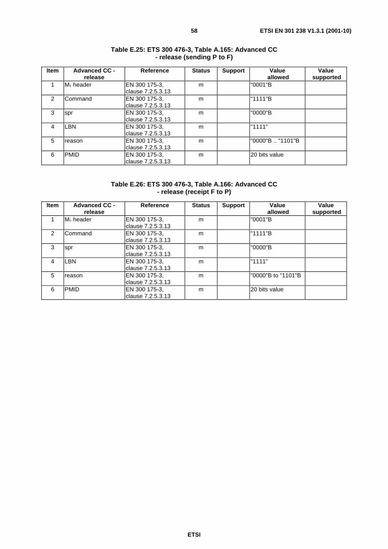
ETSI
ETSI EN 301 238 V1.3.1 (2001-10)58
Table E.25: ETS 300 476-3, Table A.165: Advanced CC - release (sending P to F)
Item Advanced CC - release
Reference Status Support Value allowed
Value supported
1 MT header EN 300 175-3, clause 7.2.5.3.13
m "0001"B
2 Command EN 300 175-3, clause 7.2.5.3.13
m "1111"B
3 spr EN 300 175-3, clause 7.2.5.3.13
m "0000"B
4 LBN EN 300 175-3, clause 7.2.5.3.13
m "1111"
5 reason EN 300 175-3, clause 7.2.5.3.13
m "0000"B .. "1101"B
6 PMID EN 300 175-3, clause 7.2.5.3.13
m 20 bits value
Table E.26: ETS 300 476-3, Table A.166: Advanced CC - release (receipt F to P)
Item Advanced CC - release
Reference Status Support Value allowed
Value supported
1 MT header EN 300 175-3, clause 7.2.5.3.13
m "0001"B
2 Command EN 300 175-3, clause 7.2.5.3.13
m "1111"B
3 spr EN 300 175-3, clause 7.2.5.3.13
m "0000"B
4 LBN EN 300 175-3, clause 7.2.5.3.13
m "1111"
5 reason EN 300 175-3, clause 7.2.5.3.13
m "0000"B to "1101"B
6 PMID EN 300 175-3, clause 7.2.5.3.13
m 20 bits value

ETSI
ETSI EN 301 238 V1.3.1 (2001-10)59
Annex F (normative): Service D2; FT Profile Implementation Conformance Statement (ICS) and Protocol Implementation Conformance Statement (PICS) proforma - Medium Access Control (MAC) layer Notwithstanding the provisions of the copyright clause related to the text of the present document, ETSI grants that users of the present document may freely reproduce the PICS proforma in this annex so that it can be used for its intended purposes and may further publish the completed PICS.
Profile status column
The standardized symbols for the status column are as follows:
m or M mandatory - the capability is required to be supported;
o or O optional - the capability may be supported or not;
n/a or N/A not applicable - in the given context, it is impossible to use the capability;
x or X prohibited (excluded) - there is a requirement not to use this capability in the given context;
o.i or O.i qualified optional - for mutually exclusive or selectable options from a set. "i" is an integer which identifies a unique group of related optional items and the logic of their selection which is defined immediately following the table;
ci or Ci conditional - the requirement on the capability ("m", "o", "x" or "n/a") depends on the support of other optional or conditional items. "i" is an integer identifying a unique conditional status expression which is defined immediately following the table or which is defined in the general condition table below;
i or I out-of-scope - this capability is outside the scope of the given specification, and hence irrelevant and not subject to conformance testing. This status is in particular applicable for data fields which are reserved for future use. The structure of such fields has to be supported, but the value is undefined and thus to be ignored.
If appropriate, a "C" followed by an integer is placed in the status column, providing a reference to a conditional status expression defined elsewhere in the PICS proforma. The following conditions are applicable throughout the entire document.
Condition identifier Condition definition C1 IF "32 kbit/s unprotected service" supported THEN m ELSE i C2 IF "unprotected rate adaptation service" supported THEN m ELSE i

ETSI
ETSI EN 301 238 V1.3.1 (2001-10)60
F.1 Service D2; FT Profile Implementation Conformance Statement (ICS) - Medium Access Control (MAC) layer
The requirements indicated in ETS 300 474-2, clause A.4 shall apply, except for the modifications and/or additions listed below:
Table F.1: ETS 300 474-2, Table A.103
Item Connection oriented control services Reference Status 1 Basic connections EN 300 444, clause 5.2 C1 2 Advanced symmetric connections EN 300 175-3,
clause 5.6.2.1 C2
Table F.2: ETS 300 474-2, Table A.104
Item Connection services Reference Status 1 Connection set-up (Basic connections) EN 300 444, clause 5.2 C1 3 Connection data transfer (Basic connections) EN 300 444, clause 5.2 C1 4 Connection handover (intra-cell, inter-cell) EN 300 444, clause 5.2 C1 5 Connection release (Basic connections) EN 300 444, clause 5.2 C1
Table F.3: ETS 300 474-2, Table A.105
Item Symmetric connection oriented services Reference Status 1 Type 1 IN_minimum_delay (General) EN 300 444,
clauses 5.2, 10.1 C1
2 Type 2 IN_normal_delay EN 300 175-3, clause 5.6.2.1
C2
Table F.4: ETS 300 474-2, Table A.115
Item Name of procedure Reference Status 1 Basic set-up, single bearer basic connection of known service
(Set-up of basic connection, basic bearer set-up (A-field)) EN 300 444, clause 10.4
C1
2 Normal set-up, single bearer duplex connection known service EN 300 175-3, clause 10.2.4.2
C2
Table F.5: ETS 300 474-2, Table A.116
Item Name of procedure Reference Status 1 Basic bearer set-up EN 300 444,
clause 10.4 C1
Table F.6: ETS 300 474-2, Table A.128: MAC control (MT) messages (receipt P to F)
Item MAC control (MT) messages Reference Status 1 Basic connection control EN 300 444,
clause 10.4 C1
3 Advanced connection control EN 300 175-3, clause 7.2.5.1
C2

ETSI
ETSI EN 301 238 V1.3.1 (2001-10)61
Table F.7: ETS 300 474-2, Table A.129: MAC control (MT) messages (sending F to P)
Item MAC control (MT) messages Prof. Ref. Prof. Status 1 Basic connection control EN 300 444,
clause 10.4 C1
3 Advanced connection control EN 300 175-3, clause 7.2.5.1
C2
F.2 Service D2; FT Protocol Implementation Conformance Statement (PICS) proforma - Medium Access Control (MAC) layer
The requirements indicated in ETS 300 476-6 shall apply, except for the modifications and/or additions listed below:
Table F.8: ETS 300 476-6, Table A.11: Connection services
Item Connection services Reference Status Support 1 Connection set-up (Advanced connections) EN 300 444,
clause 10.2 C2
2 Connection modification (Advanced connections) EN 300 444, clause 10.3
C2
3 Connection data transfer (Advanced connections) EN 300 444, clause 10.8
C2
4 Connection release (Advanced connections) EN 300 444, clause 10.4
C2
Table F.9: ETS 300 476-6, Table A.57: System Information (QT) message (sending F to P)
Item System information message Reference Status Support 4 QT - Extended fixed part capabilities EN 300 175-3,
clause 7.2.3.5 m
Table F.10: ETS 300 476-6, Table A.66: Advanced connection control messages (receipt P to F)
Item MAC control (MT) messages - Advanced connection control
Reference Status Support
1 Advanced CC - access request EN 300 175-3, clause 7.2.5.3.2
C2
2 Advanced CC - bearer handover request EN 300 175-3, clause 7.2.5.3.3
C2
3 Advanced CC - connection handover request EN 300 175-3, clause 7.2.5.3.4
C2
5 Advanced CC - bearer confirm EN 300 175-3, clause 7.2.5.3.6
C2
6 Advanced CC - wait EN 300 175-3, clause 7.2.5.3.7
C2
7 Advanced CC - attributes_T.request EN 300 175-3, clause 7.2.5.3.8
C2
8 Advanced CC - attributes_T.confirm EN 300 175-3, clause 7.2.5.3.8
C2
14 Advanced CC - release EN 300 175-3, clause 7.2.5.3.13
C2

ETSI
ETSI EN 301 238 V1.3.1 (2001-10)62
Table F.11: ETS 300 476-6, Table A.67: Advanced connection control messages (sending F to P)
Item MAC control (MT) messages - Advanced connection control
Reference Status Support
1 Advanced CC - access request EN 300 175-3, clause 7.2.5.3.2
C2
2 Advanced CC - bearer handover request EN 300 175-3, clause 7.2.5.3.3
x
3 Advanced CC - connection handover request EN 300 175-3, clause 7.2.5.3.4
C2
5 Advanced CC - bearer confirm EN 300 175-3, clause 7.2.5.3.6
C2
6 Advanced CC - wait EN 300 175-3, clause 7.2.5.3.7
C2
7 Advanced CC - attributes_T.request EN 300 175-3, clause 7.2.5.3.8
C2
8 Advanced CC - attributes_T.confirm EN 300 175-3, clause 7.2.5.3.8
C2
14 Advanced CC - release EN 300 175-3, clause 7.2.5.3.13
C2
Table F.12: ETS 300 476-6, Table A.130: Advanced CC - access request (receipt P to F)
Item Advanced CC - access request
Reference Status Support Value allowed
Value supported
1 MT header EN 300 175-3, clause 7.2.5.3.2
C2 "0001"B
2 Command EN 300 175-3, clause 7.2.5.3.2
C2 "0000"B
3 FMID EN 300 175-3, clause 7.2.5.3.2
C2 12 bits value
4 PMID EN 300 175-3, clause 7.2.5.3.2
C2 20 bits value
Table F.13: ETS 300 476-6, Table A. 131: Advanced CC - access request (sending F to P)
Item Advanced CC - access request
Reference Status Support Value allowed
Value supported
1 MT header EN 300 175-3, clause 7.2.5.3.2
C2 "0001"B
2 Command EN 300 175-3, clause 7.2.5.3.2
C2 "0000"B
3 FMID EN 300 175-3, clause 7.2.5.3.2
C2 12 bits value
4 PMID EN 300 175-3, clause 7.2.5.3.2
C2 20 bits value

ETSI
ETSI EN 301 238 V1.3.1 (2001-10)63
Table F.14: ETS 300 476-6, Table A.132: Advanced CC - bearer handover request (receipt P to F)
Item Advanced CC - bearer handover request
Reference Status Support Value allowed
Value supported
1 MT header EN 300 175-3, clause 7.2.5.3.3
C2 "0001"B
2 Command EN 300 175-3, clause 7.2.5.3.3
C2 "0001"B
3 FMID EN 300 175-3, clause 7.2.5.3.3
C2 12 bits value
4 PMID EN 300 175-3, clause 7.2.5.3.3
C2 20 bits value
Table F.15: ETS 300 476-6, Table A. 133: Advanced CC - connection handover request (receipt P to F)
Item Advanced CC - connection handover
request
Reference Status Support Value allowed
Value supported
1 MT header EN 300 175-3, clause 7.2.5.3.4
C2 "0001"B
2 Command EN 300 175-3, clause 7.2.5.3.4
C2 "0010"B
3 FMID EN 300 175-3, clause 7.2.5.3.4
C2 12 bits value
4 PMID EN 300 175-3, clause 7.2.5.3.4
C2 20 bits value
Table F.16: ETS 300 476-6, Table A.134: Advanced CC - connection handover request (sending F to P)
Item Advanced CC - connection handover
request
Reference Status Support Value allowed
Value supported
1 MT header EN 300 175-3, clause 7.2.5.3.4
C2 "0001"B
2 Command EN 300 175-3, clause 7.2.5.3.4
C2 "0010"B
3 FMID EN 300 175-3, clause 7.2.5.3.4
C2 12 bits value
4 PMID EN 300 175-3, clause 7.2.5.3.4
C2 20 bits value
Table F.17: ETS 300 476-6, Table A.137: Advanced CC - bearer confirm (receipt P to F)
Item Advanced CC - bearer confirm
Reference Status Support Value allowed
Value supported
1 MT header EN 300 175-3, clause 7.2.5.3.6
C2 "0001"B
2 Command EN 300 175-3, clause 7.2.5.3.6
C2 "0100"B
3 FMID EN 300 175-3, clause 7.2.5.3.6
C2 12 bits value
4 PMID EN 300 175-3, clause 7.2.5.3.6
C2 20 bits value

ETSI
ETSI EN 301 238 V1.3.1 (2001-10)64
Table F.18: ETS 300 476-6, Table A.138: Advanced CC - bearer confirm (sending F to P)
Item Advanced CC - bearer confirm
Reference Status Support Value allowed
Value supported
1 MT header EN 300 175-3, clause 7.2.5.3.6
C2 "0001"B
2 Command EN 300 175-3, clause 7.2.5.3.6
C2 "0100"B
3 FMID EN 300 175-3, clause 7.2.5.3.6
C2 12 bits value
4 PMID EN 300 175-3, clause 7.2.5.3.6
C2 20 bits value
Table F.19: ETS 300 476-6, Table A.139: Advanced CC - wait (receipt P to F)
Item Advanced CC - wait Reference Status Support Value allowed
Value supported
1 MT header EN 300 175-3, clause 7.2.5.3.7
C2 "0001"B
2 Command EN 300 175-3, clause 7.2.5.3.7
C2 "0101"B
3 FMID EN 300 175-3, clause 7.2.5.3.7
C2 12 bits value
4 PMID EN 300 175-3, clause 7.2.5.3.7
C2 20 bits value, "11110000 11110000 1111"B
Table F.20: ETS 300 476-6, Table A.140: Advanced CC - wait (sending F to P)
Item Advanced CC - wait Reference Status Support Value allowed
Value supported
1 MT header EN 300 175-3, clause 7.2.5.3.7
C2 "0001"B
2 Command EN 300 175-3, clause 7.2.5.3.7
C2 "0101"B
3 FMID EN 300 175-3, clause 7.2.5.3.7
C2 12 bits value
4 PMID EN 300 175-3, clause 7.2.5.3.7
C2 20 bits value, "11110000 11110000 1111"B
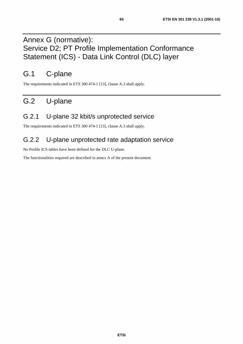
ETSI
ETSI EN 301 238 V1.3.1 (2001-10)65
Annex G (normative): Service D2; PT Profile Implementation Conformance Statement (ICS) - Data Link Control (DLC) layer
G.1 C-plane The requirements indicated in ETS 300 474-1 [13], clause A.3 shall apply.
G.2 U-plane
G.2.1 U-plane 32 kbit/s unprotected service The requirements indicated in ETS 300 474-1 [13], clause A.3 shall apply.
G.2.2 U-plane unprotected rate adaptation service No Profile ICS tables have been defined for the DLC U-plane.
The functionalities required are described in annex A of the present document.

ETSI
ETSI EN 301 238 V1.3.1 (2001-10)66
Annex H (normative): Service D2; FT Profile Implementation Conformance Statement (ICS) - Data Link Control (DLC) layer
H.1 C-plane The requirements indicated in ETS 300 474-2 [14], clause A.3 shall apply.
H.2 U-plane
H.2.1 U-plane 32 kbit/s unprotected service The requirements indicated in ETS 300 474-2 [14], clause A.3 shall apply.
H.2.2 U-plane unprotected rate adaptation service No Profile ICS tables have been defined for the DLC U-plane.
The functionalities required are described in annex A of the present document.

ETSI
ETSI EN 301 238 V1.3.1 (2001-10)67
Annex I (informative): Void

ETSI
ETSI EN 301 238 V1.3.1 (2001-10)68
Annex J (normative): Service D2; PT profile Requirement List (profile RL) and Protocol Implementation Conformance Statement (PICS) proforma - Network (NWK) layer Notwithstanding the provisions of the copyright clause related to the text of the present document, ETSI grants that users of the present document may freely reproduce the PICS proforma in this annex so that it can be used for its intended purposes and may further publish the completed PICS.
Profile status column
The standardized symbols for the status column are as follows:
m or M mandatory - the capability is required to be supported;
o or O optional - the capability may be supported or not;
n/a or N/A not applicable - in the given context, it is impossible to use the capability;
x or X prohibited (excluded) - there is a requirement not to use this capability in the given context;
o.i or O.i qualified optional - for mutually exclusive or selectable options from a set. "i" is an integer which identifies a unique group of related optional items and the logic of their selection which is defined immediately following the table;
ci or Ci conditional - the requirement on the capability ("m", "o", "x" or "n/a") depends on the support of other optional or conditional items. "i" is an integer identifying a unique conditional status expression which is defined immediately following the table or which is defined in the general condition table below;
i or I out-of-scope - this capability is outside the scope of the given specification, and hence irrelevant and not subject to conformance testing. This status is in particular applicable for data fields which are reserved for future use. The structure of such fields has to be supported, but the value is undefined and thus to be ignored.
J.1 Service D2; PT profile Requirement List (profile RL) - Network (NWK) layer
The requirements indicated in ETS 300 474-1, clause A.2 shall apply, except for the modifications and/or additions listed below:
Table J.1: ETS 300 474-1, Table A.14: CC-SETUP sending (P to F) supported
Item CC-SETUP sending (P to F) Information element name
Reference Status
5 IWU attributes EN 300 175-5, clause 7.7.2.1
m
Table J.2: ETS 300 474-1, Table A.15: CC-SETUP receiving (F to P) supported
Item CC-SETUP receiving (F to P) Information element name
Reference Status
5 IWU attributes EN 300 175-5, clause 7.7.2.1
m

ETSI
ETSI EN 301 238 V1.3.1 (2001-10)69
Table J.3: ETS 300 474-1, Table A.25: CC-RELEASE sending (P to F) supported
Item CC-RELEASE sending (P to F) Information element name
Reference Status
2 Release reason EN 300 444, clause 8.9 m
Table J.4: ETS 300 474-1, Table A.26: CC-RELEASE receiving (F to P) supported
Item CC-RELEASE receiving (F to P) Information element name
Reference Status
2 Release reason EN 300 444, clause 8.9 m
Table J.5: ETS 300 474-1, Table A.27: CC-RELEASE-COM sending (P to F) supported
Item CC-RELEASE-COM sending (P to F) Information element name
Reference Status
2 Release reason EN 300 444, clause 8.9
m
Table J.6: ETS 300 474-1, Table A.28: CC-RELEASE-COM receiving (F to P) supported
Item CC-RELEASE-COM receiving (F to P) Information element name
Reference Status
2 Release reason EN 300 444, clause 8.9
m
Table J.7: ETS 300 474-1, Table A.60: Basic service - Normal call set-up supported
Item Basic service - Normal call set-up Name of field
Reference Status Value allowed
3 Basic service EN 300 444, clause 8.2
m "1111"B
Table J.8: ETS 300 474-1, Table A.66: Release-reason supported
Item Release-reason Name of field
Reference Status Value allowed
2 Release reason code EN 300 444, clause 8.9
m -
J.2 Service D2; PT Protocol Implementation Conformance Statement (PICS) proforma - Network (NWK) layer
The requirements indicated in ETS 300 476-1 shall apply, except for the modifications and/or additions listed below:
Table J.9: ETS 300 476-1, Table A.24: LLME procedures supported
Item LLME procedures Reference Status Support 2 mgt_exchanged_attribute_negotiation EN 300 444,
clause 15.2.3 m

ETSI
ETSI EN 301 238 V1.3.1 (2001-10)70
Annex K (normative): Service D2; FT profile Requirement List (profile RL) and Protocol Implementation Conformance Statement (PICS) proforma - Network (NWK) layer Notwithstanding the provisions of the copyright clause related to the text of the present document, ETSI grants that users of the present document may freely reproduce the PICS proforma in this annex so that it can be used for its intended purposes and may further publish the completed PICS.
Profile status column
The standardized symbols for the status column are as follows:
m or M mandatory - the capability is required to be supported;
o or O optional - the capability may be supported or not;
n/a or N/A not applicable - in the given context, it is impossible to use the capability;
x or X prohibited (excluded) - there is a requirement not to use this capability in the given context;
o.i or O.i qualified optional - for mutually exclusive or selectable options from a set. "i" is an integer which identifies a unique group of related optional items and the logic of their selection which is defined immediately following the table;
ci or Ci conditional - the requirement on the capability ("m", "o", "x" or "n/a") depends on the support of other optional or conditional items. "i" is an integer identifying a unique conditional status expression which is defined immediately following the table or which is defined in the general condition table below;
i or I out-of-scope - this capability is outside the scope of the given specification, and hence irrelevant and not subject to conformance testing. This status is in particular applicable for data fields which are reserved for future use. The structure of such fields has to be supported, but the value is undefined and thus to be ignored.
K.1 Service D2; FT profile Requirement List (profile RL) - Network (NWK) layer
The requirements indicated in ETS 300 474-2, clause A.2 shall apply, except for the modifications and/or additions listed below:
Table K.1: ETS 300 474-2, Table A.27: CC-SETUP sending (P to F) supported
Item CC-SETUP sending (P to F) Information element name
Reference Status
5 IWU attributes EN 300 175-5, clause 7.7.2.1
m
Table K.2: ETS 300 474-2, Table A.28: CC-SETUP sending (F to P) supported
Item CC-SETUP sending (F to P) Information element name
Reference Status
5 IWU attributes EN 300 175-5, clause 7.7.2.1
m

ETSI
ETSI EN 301 238 V1.3.1 (2001-10)71
Table K.3: ETS 300 474-2, Table A.25: CC-RELEASE receiving (P to F) supported
Item CC-RELEASE receiving (P to F) Information element name
Reference Status
2 Release reason EN 300 444, clause 8.9
m
Table K.4: ETS 300 474-2, Table A.26: CC-RELEASE sending (F to P) supported
Item CC-RELEASE sending (F to P) Information element name
Reference Status
2 Release reason EN 300 444, clause 8.9
m
Table K.5: ETS 300 474-2, Table A.28: CC-RELEASE-COM sending (F to P) supported
Item CC-RELEASE-COM sending (F to P) Information element name
Reference Status
2 Release reason EN 300 444, clause 8.9
m
Table K.6: ETS 300 474-2, Table A.61: Basic service - Normal call set-up supported
Item Basic service - Normal call set-up Name of field
Reference Status Value allowed
3 Basic service EN 300 444, clause 8.2
m "1111"B
Table K.7: ETS 300 474-2, Table A.66: Release-reason supported
Item Release-reason Name of field
Reference Status Value allowed
2 Release reason code EN 300 444, clause 8.9
m -
K.2 Service D2; FT Protocol Implementation Conformance Statement (PICS) proforma - Network (NWK) layer
The requirements indicated in ETS 300 476-4 shall apply, except for the modifications and/or additions listed below:
Table K.8: ETS 300 476-4, Table A.24: LLME procedures supported
Item LLME procedures Reference Status Support 2 mgt_exchanged_attribute_negotiation EN 300 444,
clause 15.2.3 m
Table K.9: ETS 300 476-4, Table A.40: CC-RELEASE-COM receiving (P to F) supported
Item CC-RELEASE-COM receiving (P to F) Information element name
Reference Status Support
2 Release reason EN 300 444, clause 7.6.7
m

ETSI
ETSI EN 301 238 V1.3.1 (2001-10)72
Annex L (informative): Bibliography
• ITU-T Recommendation V.series: "Data communication over the telephone network".
• ITU-T Recommendation V.35: "Data transmission at 48 kilobits per second using 60-108 kHz group band circuits".
• ITU-T Recommendation V.21: "300 bits per second duplex modem standardized for use in the general switched telephone network".
• ITU-T Recommendation V.22: "1 200 bits per second duplex modem standardized for use in the general switched telephone network and on point-to-point 2-wire leased telephone-type circuits".
• ITU-T Recommendation V.22bis: "2 400 bits per second duplex modem using the frequency division technique standardized for use on the general switched telephone network and on point-to-point 2-wire leased telephone-type circuits".
• ITU-T Recommendation V.23: "600/1 200-baud modem standardized for use in the general switched telephone network".
• ITU-T Recommendation V.26: "2 400 bits per second modem standardized for use on 4-wire leased telephone-type circuits".
• ITU-T Recommendation V.26bis: "2 400/1 200 bits per second modem standardized for use in the general switched telephone network".
• ITU-T Recommendation V.26ter: "2 400 bits per second duplex modem using the echo cancellation technique standardized for use on the general switched telephone network and on point-to-point 2-wire leased telephone-type circuits".
• ITU-T Recommendation V.27: "4 800 bits per second modem with manual equalizer standardized for use on leased telephone-type circuits".
• ITU-T Recommendation V.27bis: "4 800/2 400 bits per second modem with automatic equalizer standardized for use on leased telephone-type circuits".
• ITU-T Recommendation V.27ter: "4 800/2 400 bits per second modem standardized for use in the general switched telephone network".
• ITU-T Recommendation V.32: "A family of 2-wire, duplex modems operating at data signalling rates of up to 9 600 bit/s for use on the general switched telephone network and on leased telephone-type circuits".
• ITU-T Recommendation V.120: "Support by an ISDN of data terminal equipment with V-Series type interfaces with provision for statistical multiplexing".
• ITU-T Recommendation H.324: "Terminal for low bit-rate multimedia communication".

ETSI
ETSI EN 301 238 V1.3.1 (2001-10)73
History
Document history
V1.1.3 June 1998 Publication
V1.2.3 April 2000 Publication
V1.3.0 June 2001 One-step Approval Procedure OAP 20011005: 2001-06-06 to 2001-10-05
V1.3.1 October 2001 Publication
Related Documents


