EN 300 462-3-1 V1.1.1 (1998-05) European Standard (Telecommunications series) Transmission and Multiplexing (TM); Generic requirements for synchronization networks; Part 3-1: The control of jitter and wander within synchronization networks

Welcome message from author
This document is posted to help you gain knowledge. Please leave a comment to let me know what you think about it! Share it to your friends and learn new things together.
Transcript

EN 300 462-3-1 V1.1.1 (1998-05)European Standard (Telecommunications series)
Transmission and Multiplexing (TM);Generic requirements for synchronization networks;
Part 3-1: The control of jitter and wander withinsynchronization networks

ETSI
EN 300 462-3-1 V1.1.1 (1998-05)2
ReferenceREN/TM-03017-3-1 (4a0r9ico.PDF)
KeywordsSynchronization, transmission, network
ETSI
Postal addressF-06921 Sophia Antipolis Cedex - FRANCE
Office address650 Route des Lucioles - Sophia Antipolis
Valbonne - FRANCETel.: +33 4 92 94 42 00 Fax: +33 4 93 65 47 16
Siret N° 348 623 562 00017 - NAF 742 CAssociation à but non lucratif enregistrée à laSous-Préfecture de Grasse (06) N° 7803/88
[email protected]://www.etsi.fr
http://www.etsi.org
Copyright Notification
No part may be reproduced except as authorized by written permission.The copyright and the foregoing restriction extend to reproduction in all media.
© European Telecommunications Standards Institute 1998.All rights reserved.

ETSI
EN 300 462-3-1 V1.1.1 (1998-05)3
Contents
Intellectual Property Rights................................................................................................................................4
Foreword ............................................................................................................................................................4
1 Scope........................................................................................................................................................6
2 Normative references ...............................................................................................................................6
3 Definitions, symbols and abbreviations...................................................................................................73.1 Definitions ......................................................................................................................................................... 73.2 Symbols ............................................................................................................................................................. 73.3 Abbreviations..................................................................................................................................................... 7
4 Basic philosophy for the control of jitter and wander .............................................................................7
5 Synchronization interfaces.......................................................................................................................8
6 Synchronization reference network .........................................................................................................9
7 Network limits for jitter and wander at synchronization interfaces.........................................................97.1 Network limits for jitter ................................................................................................................................... 107.2 Network limits for wander ............................................................................................................................... 107.2.1 Network limits for wander at PRC outputs................................................................................................. 117.2.2 Network limits for wander at SSU outputs................................................................................................. 127.2.3 Network limits for wander at SEC outputs................................................................................................. 147.2.4 Network limits for wander at PDH distribution outputs ............................................................................. 15
Annex A (normative): Anti-aliasing filter to be used for the measurement of MTIE andTDEV ..............................................................................................................17
A.1 Measurement philosophy .......................................................................................................................17
A.2 Filter specification, sampling time and measurement interval ..............................................................17
Annex B (informative): Network model underlying the network limit ............................................19
B.1 Introduction............................................................................................................................................19
B.2 Considerations on the network model....................................................................................................19
B.3 Information regarding the simulations...................................................................................................21
History..............................................................................................................................................................23

ETSI
EN 300 462-3-1 V1.1.1 (1998-05)4
Intellectual Property RightsIPRs essential or potentially essential to the present document may have been declared to ETSI. The informationpertaining to these essential IPRs, if any, is publicly available for ETSI members and non-members, and can be foundin ETR 314: "Intellectual Property Rights (IPRs); Essential, or potentially Essential, IPRs notified to ETSI in respect ofETSI standards", which is available free of charge from the ETSI Secretariat. Latest updates are available on the ETSIWeb server (http://www.etsi.fr/ipr or http://www.etsi.org/ipr).
Pursuant to the ETSI Interim IPR Policy, no investigation, including IPR searches, has been carried out by ETSI. Noguarantee can be given as to the existence of other IPRs not referenced in ETR 314 (or the updates on the ETSI Webserver) which are, or may be, or may become, essential to the present document.
ForewordThis European Standard (Telecommunications series) has been produced by the Transmission and Multiplexing (TM)Technical Committee.
The present document has been produced to provide requirements for synchronization networks that are compatible withthe performance requirements of digital networks. It is one of a family of documents covering various aspects ofsynchronization networks:
Part 1-1: "Definitions and terminology for synchronization networks";
Part 2-1: "Synchronization network architecture";
Part 3-1: "The control of jitter and wander within synchronization networks";
Part 4-1: "Timing characteristics of slave clocks suitable for synchronization supply to Synchronous DigitalHierarchy (SDH) and Plesiochronous Digital Hierarchy (PDH) equipment";
Part 4-2: "Timing characteristics of slave clocks suitable for synchronization supply to Synchronous DigitalHierarchy (SDH) and Plesiochronous Digital Hierarchy (PDH) equipment ImplementationConformance (ICS) Statement";
Part 5-1: "Timing characteristics of slave clocks suitable for operation in Synchronous Digital Hierarchy(SDH) equipment";
Part 6-1: "Timing characteristics of primary reference clocks";
Part 6-2: "Timing characteristics of primary reference clocks Implementation Conformance (ICS)Statement";
Part 7-1: "Timing characteristics of slave clocks suitable for synchronization supply to equipment in localnode applications".
Parts 1-1, 2-1, 3-1 and 5-1 have previously been published as ETS 300 462 Parts 1, 2, 3 and 5, respectively.
Additionally, parts 4-1 and 6-1 completed the Voting phase of the Two Step Approval procedure as ETS 300 462 Parts4 and 6, respectively.
It was decided to prepare ICS proformas for several of the parts and this necessitated a re-numbering of the individualdocument parts. It was also decided to create a new part 7-1.
This in turn led to a need to re-publish new versions of all six parts of the original ETS. At the same time, theopportunity was taken to convert the document type to EN.
This has involved no technical change to any of the documents. However part 5-1 has been modified, due to editorialerrors which appeared in ETS 300 462-5.

ETSI
EN 300 462-3-1 V1.1.1 (1998-05)5
Transposition dates
Date of adoption 3 January 1997
Date of latest announcement of this ETS (doa): 30 April 1997
Date of latest publication of new National Standardor endorsement of this ETS (dop/e): 31 October 1997
Date of withdrawal of any conflicting National Standard (dow): 31 October 1997
NOTE: The above transposition table is the original table from ETS 300 462-3 (January 1997, see History).

ETSI
EN 300 462-3-1 V1.1.1 (1998-05)6
1 ScopeThe present document outlines requirements for the control of jitter and wander within synchronization Networks thatare constructed according to the architectural principles described in EN 300 462-2-1 [2]. A synchronization networkthat complies with the network limits for jitter and wander specified in the present document will be suitable for thesynchronization of Synchronous Digital Hierarchy (SDH) and Public Switched Telephone Network (PSTN) networks. Itcombines the short term stability requirements of SDH networks with the long term stability requirements of the PSTN.The values specified in the present document refer to the design of new synchronization networks. They do notnecessarily represent the performance of existing PSTN synchronization networks.
The network limits specified in the present document form the network requirements from which the clock specificationsin EN 300 462-4-1 [3], EN 300 462-5-1 [4] and EN 300 462-6-1 [5] have been derived.
2 Normative referencesThe following documents contain provisions which, through reference in this text, constitute provisions of the presentdocument.
• References are either specific (identified by date of publication, edition number, version number, etc.) ornon-specific.
• For a specific reference, subsequent revisions do not apply.
• For a non-specific reference, subsequent revisions do apply.
• A non-specific reference to an ETS shall also be taken to refer to later versions published as an EN with the samenumber.
[1] EN 300 462-1-1: "Transmission and Multiplexing (TM); Generic requirements for synchronizationnetworks; Part 1-1: Definitions and terminology for synchronization networks".
[2] EN 300 462-2-1: "Transmission and Multiplexing (TM); Generic requirements for synchronizationnetworks; Part 2-1: Synchronization network architecture".
[3] EN 300 462-4-1: "Transmission and Multiplexing (TM); Generic requirements for synchronizationnetworks; Part 4-1: Timing characteristics of slave clocks suitable for synchronization supply toSynchronous Digital Hierarchy (SDH) and Plesiochronous Digital Hierarchy (PDH) equipment".
[4] EN 300 462-5-1: "Transmission and Multiplexing (TM); Generic requirements for synchronizationnetworks; Part 5-1: Timing characteristics of slave clocks suitable for operation in SynchronousDigital Hierarchy (SDH) equipment".
[5] EN 300 462-6-1: "Transmission and Multiplexing (TM); Generic requirements for synchronizationnetworks; Part 6-1: Timing characteristics of primary reference clocks".
[6] ITU-T Recommendation G.822: "Controlled slip rate objectives on an international digitalconnection".
[7] ITU-T Recommendation G.823: "The control of jitter and wander within digital networks whichare based on the 2 048 kbit/s hierarchy".
[8] ITU-T Recommendation O.171: "Timing jitter measuring equipment for digital systems".
[9] ITU-T Recommendation G.783: "Characteristics of synchronous digital hierarchy (SDH)equipment functional blocks".

ETSI
EN 300 462-3-1 V1.1.1 (1998-05)7
3 Definitions, symbols and abbreviations
3.1 DefinitionsFor the purposes of the present document, the definitions given in EN 300 462-1-1 [1] apply.
3.2 SymbolsFor the purposes of the present document the symbols and diagrammatic conventions described in EN 300 462-1-1 [1]apply.
3.3 AbbreviationsFor the purposes of the present document the abbreviations given in EN 300 462-1-1 [1], together with the following,apply:
MTIE Maximum Time Interval ErrorPDH Plesiochronous Digital HierarchyPSTN Public Switched Telephone NetworkPRC Primary Reference ClockSDH Synchronous Digital HierarchySEC SDH Equipment ClockSSU Synchronization Supply UnitSTM-N Synchronous Transport Module, level NTDEV Time DEViationUTC Universal Time Co-ordinated
4 Basic philosophy for the control of jitter and wanderThe present multi-part document describes the synchronization network as a logically distinct network layer with its ownplanning rules and performance requirements. The philosophy for the control of jitter and wander in the synchronizationnetwork layer is the same as applied to the payload carrying layers of the transport network, which can be found inITU-T Recommendation G.823 [7]. It is based on the need to recommend a maximum network limit that should not beexceeded at any synchronization interface. This network limit represents the worst case accumulation of jitter andwander within the synchronization network reference chain shown in figure 5 of EN 300 462-2-1 [2]. The main purposefor defining a network limit is that it provides the maximum amount of jitter and wander that any synchronizationelement in the network may experience at its input, since the network limit should not be exceeded at the output of asynchronization element anywhere in the network. The network limits therefore provide indirectly the requirements forthe lower limit of maximum tolerable jitter and wander at the input of synchronization elements.
The wander tolerance of the large installed base of 64 kbit/s digital switches, i.e. the differential wander that a switchwill tolerate before giving rise to controlled slip, together with the slip performance objectives stated in ITU-TRecommendation G.822 [6], have to be respected when introducing new transport technologies in the network. Thisdifferential wander is the cumulative effect of wander in the synchronization network and the wander that the transportof the data between switches may introduce. In the case of SDH, in most implementations, the latter is dependent on thewander that the SDH network elements experience at their synchronization inputs. The wander in a synchronizationnetwork that is also suitable for the synchronization of SDH therefore needs to be controlled to a level that is compatiblewith the slip performance objectives of the 64 kbit/s switched network.
It should be noted that the implication of the network limit definition is, that in practical networks the jitter and wandervalues at most synchronization interfaces should be well within the network limits, because the network limits will onlyappear at the end of a synchronization chain that is as long as the reference chain.

ETSI
EN 300 462-3-1 V1.1.1 (1998-05)8
5 Synchronization interfacesThe synchronization interfaces that are specified in the present document are depicted in figure 1. This figure is anexpanded version of figure 6 of EN 300 462-2-1 [2] showing examples of actual physical interfaces that may appear insynchronization networks. Universal Time Co-ordinated (UTC) is indicated in the figure as the reference relative towhich all network limits are specified. Because of the way it is defined, there is no physical entity or interface associatedwith UTC. Two alternative synchronization distribution methods may be used between Synchronization Supply Unit(SSUs), and between Primary Reference Clock (PRC) and SSUs. SDH distribution makes use of the SDH section layerand may be a cascade of sections with at most 20 intermediate SDH network elements, each containing an SDHEquipment Clock (SEC). Plesiochronous Digital Hierarchy (PDH) distribution makes use of a 2 Mbit/s PDH path thatmay be traversing a number of intermediate PDH multiplexing stages and PDH line systems. These are not shownexplicitly, because they do not contain clocks that are subject to the present document.
SSUG.812
SSUG.812
Synchronization interface at a PDH synchronization distribution output for which the network limit applies
Synchronization interface at a SEC output for which the networklimit applies
Synchronization interface at a SSU output for which the network limit applies
Synchronization interface at a PRC output for which the networklimit applies.
Note 1
.
.
.
.
Note: The maximum number ofclocks in these chains is specifiedin EN 300 462-2-1 [2]
Note
Note
Note
Figure 1: Synchronization reference chain showing where the network limits apply
Figure 1 shows that four types of synchronization interfaces can be distinguished in the synchronization network:
- synchronization interfaces at PRC outputs;

ETSI
EN 300 462-3-1 V1.1.1 (1998-05)9
- synchronization interfaces at SSU outputs;
- synchronization interfaces at SEC outputs;
- synchronization interfaces at PDH distribution outputs.
The present document therefore provides four sets of network limit requirements, one for each type of interface.
6 Synchronization reference networkThe synchronization reference chain defined in figure 5 of EN 300 462-2-1 [2] has to support not only a homogeneousSDH transport network, to which the transport network will evolve sooner or later, but also the evolution towards an allSDH transport network. In the transitional period, a mixed situation will exist where data paths may traverse both PDHand SDH sub-networks. The additional PDH/SDH mappings give rise to an increase of the wander that the data path isexperiencing because the wander that appears at the output of one SDH island is passed on transparently throughsubsequent islands via the asynchronous mapping process. It is therefore the transitional period which puts the moststringent requirements on the performance of the synchronization network.
To provide for consistency between the specifications of the individual synchronization elements and the network limitsan iterative process has been followed. The accumulation of wander in the synchronization reference network has beencalculated based on a set of assumptions on:
- the number and performance of individual synchronization elements;
- the number and size of transients in the synchronization network;
- the level of diurnal wander.
The resulting quality of the synchronization network has then been applied to a reference model for the data path of foursynchronous islands. Subsequently, the set of assumptions has been varied until a combination was found that met therequirement for the average differential wander experienced by a slip buffer terminated equipment (e.g. a 64 kbit/sexchange) of less than 18 µs measured over one day. The assumptions that were found to meet this requirement aredocumented in annex B.
It is stressed however that many other combinations of assumptions are conceivable that will comply with the networklimits resulting from the set given in annex B. These are elaborated in this informative annex for guidance only.Provided these assumptions are fulfilled, the 18 µs wander limit will be met also across multiple operator domains.
A network operator may use a different set of rules, e.g. with a different number of SSUs and other assumptions aboutthe transients in the synchronization chain, provided the synchronization network limits for jitter and wander specified inthe present document are adhered to.
7 Network limits for jitter and wander at synchronizationinterfaces
The specification of network limits for synchronization interfaces is primarily intended to reflect the results of atheoretical analysis of the worst case accumulation of jitter and wander in a synchronization network. These values thenserve to specify tolerance requirements for synchronization equipment. It should, however, also be possible to verifythrough measurements in a real network that a particular interface does not exceed the specified limits. The location ofthe interface in the synchronization chain of that network determines what margin may be expected with reference to thenetwork limits.
As shown in figure 1, an SSU may receive its timing via SDH or PDH distribution. The network limit at the output ofthese distribution chains represents the amount of jitter and wander that an SSU may experience at its input. Since thereis more jitter allowed at PDH interfaces than at SDH Synchronous Transport Module, level N (STM-N) interfaces, thenetwork limit for the PDH distribution outputs represents the worst case that the SSU should tolerate at its inputs. Thejitter and wander tolerance of a SEC should be (at least) the amount of jitter at the input of the last SEC of asynchronization chain. Since the contribution of the last SEC in the chain to the network limit at SEC outputs- that is the

ETSI
EN 300 462-3-1 V1.1.1 (1998-05)10
amount of jitter and wander that may be expected at the output of the last SEC of the chain - is small, the network limitin the SEC output can be used as the jitter and wander tolerance requirement for a SEC.
From the large number of available timing characteristics a subset has been selected to constrain both thestandardization as well as the operational verification effort. The selected characteristics are considered to providesufficient information to ensure satisfactory operation of PSTN and SDH networks.
7.1 Network limits for jitterThe maximum allowable high frequency noise components of a timing signal are specified by the network limits forjitter.
The theoretical arrangement for measuring output jitter at a synchronization interface is illustrated in figure 2. Thisfigure does not imply an implementation. Jitter is measured using measurement bandwidths of f1-f4 and f3-f4 with first-order 20 dB/decade roll-off characteristics and shall not exceed the limits B1 and B2 indicated in table 1 when measuredover a 60 second interval. More details about the measurement set-up can be found in ITU-T RecommendationO.171 [8].
Table 1: Network limits for jitter at PRC, SSU, SEC and PDH distribution outputs
Network limits at: f1 [Hz] f3 [Hz] f4 [kHz] B1 [UIpp] B2 [UIpp]PRC outputs 20 - 100 0,05 -SSU outputs 20 - 100 0,05 -SEC outputs 20 49 100 0,5 0,2PDH distribution outputs 20 18 000 100 1,5 0,2NOTE: For 2 Mbit/s and 2 MHz synchronization interfaces, UIpp refers to the reciprocal of the bit rate. For
interfaces at other bit rates carrying synchronization the corresponding value in units of time applies.
Bandpass filtercut-off f1-f4
Bandpass filtercut-off f3-f4
B1
B2
Jitterdetector
B1, B2 : Measured jitter amplitude
Signal from asynchronization
interface
Figure 2: Theoretical measurement arrangement for jitter at a synchronization interface
7.2 Network limits for wanderThe two timing parameters that have been selected to characterize transients and low frequency noise on asynchronization interface are Maximum Time Interval Error (MTIE) and Time Deviation (TDEV). Detailed definitionsof MTIE and TDEV can be found in EN 300 462-1-1 [1]. MTIE is considered useful to capture the phase transients in atiming signal, since it describes the maximum phase variation of a timing signal over a time period. MTIE is inadequateto show the underlying noise on the timing signal, because of its sensitivity to phase transients. Random noise is bettercharacterized by TDEV which is an RMS power estimator instead of a peak estimator. TDEV tends to remove transientsin a timing signal, and is therefore a better estimator of the underlying noise processes. To be strictly correct, transientsand periodic components should be removed from data prior to calculating TDEV. This is not appropriate however formeasurements on network interfaces since there is no a priori knowledge of the types of disturbances experienced in thetiming signal. This means that it cannot be guaranteed that the TDEV results from processing of raw phase data truly

ETSI
EN 300 462-3-1 V1.1.1 (1998-05)11
reflect the random noise processes in a timing signal on a network interface, but they can provide a good estimate (referto clause B.3 of EN 300 462-1-1 [1]).
Wander is the result of random processes and therefore measurement results will vary over time and over the populationof interfaces that is being considered. The network limits which are specified in this standard represent the 2 σ value of aset of measurements for a particular interface. In other words, 95 % of all measurements at any interface should bebelow the network limit masks for that interface.
The sampling time τo and the anti-aliasing filter to be used for the measurement of MTIE and TDEV are provided inannex A.
At very low frequencies also, synchronization networks are transparent to wander. Consequently, two signals received inthe same node that derive their timing from the same source but over different paths may in the worst case have oppositephase deviation. The minimum wander tolerance in the frequency range where relevant equipment is affected by thedifferential phase variation between two inputs is therefore higher than the network limit for absolute wander. Theperformance of a clock is only influenced by the phase variations that it is experienced at the selected synchronizationinput. That is why the absolute network limits in the subsequent sections can be used directly to specify jitter and wandertolerance of the SSU and SEC.
7.2.1 Network limits for wander at PRC outputs
The maximum wander that may be generated at the output of a PRC, expressed in MTIE shall not exceed the limitsgiven in table 2.
Table 2: Network limit for wander at PRC outputs expressed in MTIE
MTIE Observation Interval25 ns 0,1 < τ ≤ 83 s
0,3 τ ns 83 < τ ≤ 1 000 s300 ns 1 000 < τ ≤ 30 000 s
0,01 τ ns τ > 30 000 s
The resultant overall specification is illustrated in figure 3.
1
10
100
1000
10000
0.1 1 10 100 1000 10000 100000
Observation interval (s)
MT
IE (
ns)
Figure 3: Network limit for wander at PRC outputs expressed in MTIE
The maximum wander that may be generated at the output of a PRC, expressed in TDEV shall not exceed the limitsgiven in table 3.

ETSI
EN 300 462-3-1 V1.1.1 (1998-05)12
Table 3: Network limit for wander at PRC outputs expressed in TDEV
TDEV Observation Interval3 ns 0,1 < τ ≤ 100 s
0,03 τ ns 100 < τ ≤ 1 000 s29,7 + 0,000 3 τ ns 1 000 < τ ≤ 1 000 000 s
At observation intervals larger than 1 million seconds other effects than covered by the formula above play a role inPRCs. For this reason the TDEV specifications in this standard are truncated at 1 million seconds. For longerobservation intervals the network limits are sufficiently characterized by the MTIE specification.
The overall specification expressed in TDEV is shown in figure 4.
1
10
100
1000
0.1 1 10 100 1000 10000 100000
Observation interval (s)
TD
EV
(ns
)
Figure 4: Network limit for wander at PRC outputs expressed in TDEV
7.2.2 Network limits for wander at SSU outputs
The maximum wander that may be generated at the output of an SSU, expressed in MTIE shall not exceed the limitsgiven in table 4.
Table 4: Network limit for wander at SSU outputs expressed in MTIE
MTIE Observation Interval25 ns 0,1 < τ ≤ 2,5 s
10 τ ns 2,5 < τ ≤ 200 s2 000 ns 200 < τ ≤ 2 000 s
433 τ0,2 + 0,01 τ ns τ > 2 000 s
The resultant overall specification is illustrated in figure 5. Note that the values are relative to UTC, i.e. they include thewander of the PRC.

ETSI
EN 300 462-3-1 V1.1.1 (1998-05)13
1
10
100
1000
10000
0.1 1 10 100 1000 10000 100000
Observation interval (s)
MT
IE (
ns)
Figure 5: Network limit for wander at SSU outputs expressed in MTIE
The maximum wander that may be generated at the output of an SSU, expressed in TDEV shall not exceed the limitsgiven in table 5.
Table 5: Network limit for wander at SSU outputs expressed in TDEV
TDEV Observation Interval3 ns 0,1 < τ ≤ 4,3 s
0,7 τ ns 4,3 < τ ≤ 100 s58 + 1,2 τ1/2 + 0,000 3 τ ns 100 < τ ≤ 1 000 000 s
The resultant overall specification is illustrated in figure 6.
1
10
100
1000
0.1 1 10 100 1000 10000 100000
Observation interval (s)
TD
EV
(ns
)
Figure 6: Network limit for wander at SSU outputs expressed in TDEV

ETSI
EN 300 462-3-1 V1.1.1 (1998-05)14
7.2.3 Network limits for wander at SEC outputs
The maximum wander that may be generated at the output of a SEC, expressed in MTIE shall not exceed the limitsgiven in table 6.
Table 6: Network limit for wander at SEC outputs expressed in MTIE
MTIE Observation Interval250 ns 0,1 < τ ≤ 2,5 s
100 τ ns 2,5 < τ ≤ 20 s2 000 ns 20 < τ ≤ 2 000 s
433 τ0,2 + 0,01 τ ns τ > 2 000 s
The resultant overall specification is illustrated in figure 7. Note that the values are relative to UTC, i.e. they include thewander of the PRC.
10
100
1000
10000
0.1 1 10 100 1000 10000 100000
Observation interval (s)
MT
IE (
ns)
Figure 7: Network limit for wander at SEC outputs expressed in MTIE
The maximum wander that may be generated at the output of a SEC, expressed in TDEV shall not exceed the limitsgiven in table 7.
Table 7: Network limit for wander at SEC outputs expressed in TDEV
TDEV Observation Interval12 ns 0,1 < τ ≤ 17,14 s
0,7 τ ns 17,14 < τ ≤ 100 s58 +1,2 τ1/2 + 0,000 3 τ ns 100 < τ ≤ 1 000 000 s
The network limit for wander at a SEC output expressed in TDEV is shown in figure 8.

ETSI
EN 300 462-3-1 V1.1.1 (1998-05)15
1
10
100
1000
0.1 1 10 100 1000 10000 100000
Observation interval (s)
TD
EV
(ns
)
Figure 8: Network limit for wander at SEC outputs expressed in TDEV
7.2.4 Network limits for wander at PDH distribution outputs
The maximum wander that may be experienced at the output of the PDH distribution outputs, expressed in MTIE shallnot exceed the values given in table 8.
Table 8: Network limit for wander at PDH distribution outputs expressed in MTIE
MTIE Observation Interval732 ns 0,1 < τ ≤ 7,3 s
100 τ ns 7,3 < τ ≤ 20 s2 000 ns 20 < τ ≤ 2 000 s
433 τ0,2 + 0,01 τ ns τ > 2 000 s
The resultant overall specification is illustrated in figure 9.
10
100
1000
10000
0.1 1 10 100 1000 10000 100000
Observation interval (s)
MT
IE (
ns)
Figure 9: Network limit for wander at PDH distribution outputs expressed in MTIE

ETSI
EN 300 462-3-1 V1.1.1 (1998-05)16
The maximum wander that may be generated at PDH distribution outputs expressed in TDEV shall not exceed the limitsgiven in table 9.
Table 9: Network limit for wander at PDH distribution outputs expressed in TDEV
TDEV Observation Interval34 ns 0,1 < τ ≤ 48 s
0,7 τ ns 48 < τ ≤ 100 s58 + 1,2 τ1/2 + 0,000 3 τ ns 100 < τ ≤ 1 000 000 s
The network limit for wander at PDH distribution outputs expressed in TDEV is shown in figure 10.
1
10
100
1000
0.1 1 10 100 1000 10000 100000
Observation interval (s)
TD
EV
(ns
)
Figure 10: Network limit for wander at PDH distribution outputs expressed in TDEV
ETSI
EN 300 462-3-1 V1.1.1 (1998-05)17
Annex A (normative):Anti-aliasing filter to be used for the measurement of MTIEand TDEV
A.1 Measurement philosophyThe measurement of TDEV of a timing signal on a network interface is intended to characterize the random noiseprocesses in the signal. To be strictly correct, transients and periodic components should be removed from themeasurement data prior to calculating TDEV, to get as good an estimate of the random processes as possible. This ishowever not practical for measurements on network interfaces since there is no a priori knowledge of the type ofdisturbances to be expected. Furthermore, the use of individual judgement to remove certain components from thetiming data would lead to ambiguous results which is undesirable for the specification of network interfaces.
For this reason TDEV shall be calculated from the raw measurement data. It is also important for consistency inmeasuring MTIE and TDEV parameters that an anti-aliasing filter, maximum sampling time and measurement intervalare specified. These are given below.
A.2 Filter specification, sampling time and measurementinterval
For observation intervals of 0,1 s to 1 000 s, MTIE and TDEV shall be measured through an equivalent 10 Hz, first-order, low-pass measurement filter, at a maximum sampling time τ0 of 1/30 seconds. The minimum measurement periodT for TDEV is twelve times the observation interval τ.
For observation intervals of 10 s to 100 000 s, MTIE and TDEV shall be measured through an equivalent 0,1 Hz, first-order, low-pass measurement filter, at a maximum sampling time τ0 of 3,3 seconds. The minimum measurement periodT for TDEV is twelve times the observation interval τ.
Note that for any other range of observation intervals the maximum sampling time τ0 and the measurement filter cut-offfrequency fc should have the same ratio to the minimum observation interval τmin as used above, i.e.τ0 = τmin / 3 and fc = 1 / τmin Hz.
The anti-aliasing measurement filter characteristic shall, for the purpose of testing conformance to the masks in thisstandard be designed to ensure that measurement accuracy due to the variance in filter performance for flicker phasenoise is better than 8 % with respect to an ideal first order low pass filter. Note that overall measurement accuracy isalso affected by a number of other factors, such as test equipment gain accuracy, measurement time, temperaturestability, MTIE/TDEV calculation algorithm, and so on.
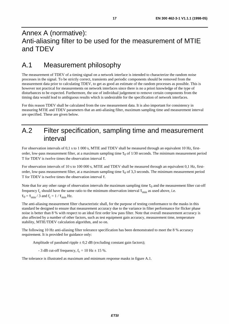
The following 10 Hz anti-aliasing filter tolerance specification has been demonstrated to meet the 8 % accuracyrequirement. It is provided for guidance only:
Amplitude of passband ripple ± 0,2 dB (excluding constant gain factors);
- 3 dB cut-off frequency, fc = 10 Hz ± 15 %.
The tolerance is illustrated as maximum and minimum response masks in figure A.1.

ETSI
EN 300 462-3-1 V1.1.1 (1998-05)18
0.1 1 1040
30
20
10
0
Max
Min
Nom
Frequency
410
NormalizedGain(dB)
(Hz)100 1000
( )f
H ff
f
f f
H f f f
H ff
f
f f
H f f f
c
Max
c
c
Max c
Min
c
c
Min c
=
= +
+
<
= − ≥
= − +
+
<
= −∞ ≥
10
0 2 201
1131
36 3
30 36 3
0 2 201
0 871
10
10
10 2
10 2
Hz
dB for
dB for
dB for
dB for
, log
,
,
( ) ,
( ) , log
,
( )
Figure A.1: Wander measurement filter characteristic and tolerance limits

ETSI
EN 300 462-3-1 V1.1.1 (1998-05)19
Annex B (informative):Network model underlying the network limit
B.1 IntroductionThe method of deriving network limits is based on numerical simulations carried out on a certain network model, that isrepresentative of a "reasonable worst case" network from the point of view of synchronization. A description of thisreference network and other assumptions that went into the composition of the network limits, are outlined in this annex.
B.2 Considerations on the network modelThe synchronization network limits are a compromise between several conflicting requirements, since one needs to alignspecifications of the individual equipment with the performance criteria that are applicable to the network as a whole.The number of possible networks that are and can be built is almost without bounds, therefore a reference network isneeded that is "worse" than the large majority of the real networks from a synchronization point of view. The list belowcontains the most important elements that need to be considered when a reference network is constructed:
- the first element is the specification of individual clocks that are part of the synchronization trail to a networkelement: the more phase noise each clock is allowed to produce the higher the network limit will be. These noisespecifications are those that can be found in EN 300 462-4-1 [3], EN 300 462-5-1 [4] and EN 300 462-6-1 [5],for SSUs, SECs and PRCs, respectively;
- the composition of the complete synchronization chain in terms of how many clocks of each type (PRC, SSU orSEC) are cascaded and in what order is the second important element. Such a synchronization reference chain isdefined in EN 300 462-2-1 [2] and consists of one PRC followed by 10 SSUs and 20 SECs (there may be 40more SECs between the SSUs but those are of no consequence for the problem at hand);
- apart from the noise generated by the individual clocks, also diurnal wander and the phase transients that occuron the synchronization links are a factor. The (conservative) assumption was that between any two SSUs therewill be on average one transient per 25 days. The size of each transient was taken to be 1 µs with randompolarity. Compared to the cumulative effect of clock noise and transients, the effect of diurnal wander isnegligible if the synchronization trail is in the main transported over buried optical cable.
The three items mentioned above completely determine the network limit for synchronization interfaces. However, adata reference network is needed to verify whether these limits are consistent with existing performance requirements:
- the important aspects of the architecture of the reference data connection are those that influence the wanderaccumulation of the data signal, hence the number of SDH islands on the link and the number of pointerprocessors inside each island. This reference data connection should be representative for any 2 048 kbit/s linkbetween two equipments that have slip-buffer termination (e.g. two international gateway switches), this isbecause an equipment with slip-buffer termination completely re-times the signal. The reference data connectionwas chosen to consist of 4 SDH islands, each having 8 TU-12 pointer processors, in an otherwise PDHconnection. The network model also (conservatively) assumes that each node that needs timing is synchronizedvia an independent worst case synchronization chain;
- finally, the performance requirements against which the resulting differential wander on the receiving slip-bufferis to be evaluated are specified in ITU-T Recommendations G.822 [6] and G.823 [7]. ITU-T RecommendationG.823 [7] prescribes a maximum amount of differential input wander of 18 µs over a time period that wasdecided to be 24 hours. ITU-T Recommendation G.822 [6] specifies a slip performance better than 0,3 per day(98,9 % of the time) for the national part of a 27 500 km reference connection. This national part was consideredto be the right benchmark for the proposed network.
The elements in the list above lead to the network shown in figure B.1. This model is derived from figure C.1 ofITU-T Recommendation G.823 [7], but it includes multiple PRCs to make it applicable for data paths that traversemultiple PRC timing domains.

ETSI
EN 300 462-3-1 V1.1.1 (1998-05)20
PRC
SSU # 1
SSU# 1 0
S EC #1
S EC # 18
S EC # 19
PR C
S S U # 1
S S U# 1 0
#1
#1 8
#1 9
PRC
S S U # 1
S S U# 1 0
#1
#1 8
#19
PRC
S S U # 1
S S U# 10
PR C
S S U # 1
S S U# 1 0
#1
#18
#19
PRC
S S U # 1
SSU# 1 0
#1
#18
#19
Equ ipm en tw / s lip-bu ffe rterm ina tion
S D H is land # 1
SD H is la nd # 4
E quipm entw / slip-buffe rterm ination
U T C
In depe nde n tS yn ch ro n iza tio n
T ra ils
S EC # 19
S EC # 18
S EC #1
D ata W ander A ccum ula tion
S EC# 2 0
T UPP# 1
S EC#20
T UP P# 2
S EC#20
T UPP# 3
S EC# 2 0
T UPP# 7
S EC# 2 0
T UPP# 8
P LL
DS
In d ep e n d e n t s y n c tra i ls fr o m U T C
S D H is lan d co n ta in in g 8 p o in te r p ro c e sso rs
20 48 k b it / sco n ne c t io n
Figure B.1: Network model for data and clock wander accumulation
To determine the differential wander at the input of the receiving slip-buffer terminating equipment, two other factorsare of importance, which were not directly included in the simulations, but for which separate allocations have beenmade in the wander budget (see also clause B.3):

ETSI
EN 300 462-3-1 V1.1.1 (1998-05)21
- the mapping wander of 2 Mbit/s signals into VC-12 has to be taken into account;
- the diurnal wander caused by environmental influences on the optical fibres that carry the signals underconsideration has to be taken into account.
B.3 Information regarding the simulationsFigure B.2 depicts the model that was used in the simulations to generate the noise on the clock inputs of all SDHequipment along the data path and the transmitting and receiving slip-buffer terminating equipments. The intrinsic noiseand the transients are generated separately. The intrinsic noise of one PRC and 10 SSUs followed by 20 SECs is basedon data from EN 300 462-4-1 [3], EN 300 462-5-1 [4] and EN 300 462-6-1 [5].
Σ
Σ
Σ
NoiseSource
TDEVfilter
Intrinsic noise
Transients (average: 0,04/day size: 1000 ns)
SSU filter action (0,01 Hz)
Transients
Network ElementTiming Input Signal
10 SSUs
Transients (average: 0,04/day size: 1000 ns)
Transients (average: 0,04/day size: 1000 ns)
SSU filter action (0,01 Hz)
SSU filter action (0,01 Hz)
Figure B .2: Clock noise generator in simulation program
For the purpose of the simulations, some more assumptions had to be made to keep the complexity to an acceptablelevel without affecting the results significantly:
- the elastic stores in the TU-12 pointer processors are taken to be two bytes. This is the minimum elastic storespace as prescribed by ITU-T Recommendation G.783 [9];
- the mapping method of the 2 Mbit/s data stream into the VC-12 is taken to be asynchronous;

ETSI
EN 300 462-3-1 V1.1.1 (1998-05)22
- the initial buffer fill of the TU-12 pointer processor elastic stores is random with a uniform distribution. Toeliminate the effect of initial distribution, the first 50 000 points of each simulation run were discarded;
- the time-increment between subsequent phase points is taken to be 1 s;
- the desynchronizer filters have not been taken into account, as this does not affect the long-term effects that areof importance when evaluating wander and slip performance.
Some factors that were not included in the simulations are:
- the diurnal wander caused by environmental influences on the optical fibres that carry the data signals underconsideration has not been taken into account. This effect is separately accounted for, by allocating 1 µs in thewander budget. This number is based on a fibre optical link of 6 000 km length, subject to a temperature changeof 2°C and with a temperature coefficient of 85 ps/km/ °C;
- the mapping wander of 2 Mbit/s signals into VC-12 was not included, but was accounted for, afterwards, byallocating 2 µs in the wander budget to cater for this effect. This number is based on the argument that the VC-12mapping wander is at most 2 UI for one island. It is assumed that the wander processes are uncorrelated. RMSaddition is therefore allowed. For four islands, a wander budget of 4 UI (corresponding to 2 µs at 2 Mbit/s) isallocated;
- the effect of AU-4 pointer processing has entirely been neglected, given the complication of including it in thesimulations and since its contribution is not significant;
- the wander that is caused by PDH multiplexing and line equipment that is part of the reference connection wasalso considered to be a small contributor and was not taken into account in the simulations.
From the above listed allocation, the following budget for the 18 µs can be derived:
Diurnal wander due to environmental effects: 1,0 µs
Mapping wander due to bit-asynchronous 2 Mbit/s mapping: 2,0 µs
Wander caused by clock noise and transients: 15,0 µs
Total: 18,0 µs
Simulations on the network model of figure B.1 show that the differential wander on the input of the receiving slipbuffer caused by clock noise is 12,6 µs over 24 hour (averaged MTIE over 40 runs of 800 Ks). The correspondingslip-rate is 0,016 slips/day on average. Thus, the above assumptions and network model lead to a consistent set ofspecifications.

ETSI
EN 300 462-3-1 V1.1.1 (1998-05)23
History
Document history
Edition 1 April 1996 Public Enquiry as ETS 300 462-3 PE 105: 1996-04-08 to 1996-08-30
Edition 1 November 1996 Vote as ETS 300 462-3 V 114: 1996-11-04 to 1996-12-27
Edition 1 January 1997 Publication as ETS 300 462-3
V1.1.1 May 1998 Publication (Converted to EN 300 462-3-1)
ISBN 2-7437-2206-1Dépôt légal : Mai 1998
Related Documents