ETSI EN 300 135-1 V1.2.1 (2008-02) European Standard (Telecommunications series) Electromagnetic compatibility and Radio spectrum Matters (ERM); Land Mobile Service; Citizens' Band (CB) radio equipment; Angle-modulated Citizens' Band radio equipment (PR 27 Radio Equipment); Part 1: Technical characteristics and methods of measurement

Welcome message from author
This document is posted to help you gain knowledge. Please leave a comment to let me know what you think about it! Share it to your friends and learn new things together.
Transcript
ETSI EN 300 135-1 V1.2.1 (2008-02)
European Standard (Telecommunications series)
Electromagnetic compatibilityand Radio spectrum Matters (ERM);
Land Mobile Service;Citizens' Band (CB) radio equipment;
Angle-modulated Citizens' Band radio equipment(PR 27 Radio Equipment);
Part 1: Technical characteristics andmethods of measurement
ETSI
ETSI EN 300 135-1 V1.2.1 (2008-02) 2
Reference REN/ERM-TGDMR-267-1
Keywords CB, radio, testing
ETSI
650 Route des Lucioles F-06921 Sophia Antipolis Cedex - FRANCE
Tel.: +33 4 92 94 42 00 Fax: +33 4 93 65 47 16
Siret N° 348 623 562 00017 - NAF 742 C
Association à but non lucratif enregistrée à la Sous-Préfecture de Grasse (06) N° 7803/88
Important notice
Individual copies of the present document can be downloaded from: http://www.etsi.org
The present document may be made available in more than one electronic version or in print. In any case of existing or perceived difference in contents between such versions, the reference version is the Portable Document Format (PDF).
In case of dispute, the reference shall be the printing on ETSI printers of the PDF version kept on a specific network drive within ETSI Secretariat.
Users of the present document should be aware that the document may be subject to revision or change of status. Information on the current status of this and other ETSI documents is available at
http://portal.etsi.org/tb/status/status.asp
If you find errors in the present document, please send your comment to one of the following services: http://portal.etsi.org/chaircor/ETSI_support.asp
Copyright Notification
No part may be reproduced except as authorized by written permission. The copyright and the foregoing restriction extend to reproduction in all media.
© European Telecommunications Standards Institute 2008.
All rights reserved.
DECTTM, PLUGTESTSTM, UMTSTM, TIPHONTM, the TIPHON logo and the ETSI logo are Trade Marks of ETSI registered for the benefit of its Members.
3GPPTM is a Trade Mark of ETSI registered for the benefit of its Members and of the 3GPP Organizational Partners.
ETSI
ETSI EN 300 135-1 V1.2.1 (2008-02) 3
Contents
Intellectual Property Rights ................................................................................................................................6
Foreword.............................................................................................................................................................6
1 Scope ........................................................................................................................................................7
2 References ................................................................................................................................................8 2.1 Normative references .........................................................................................................................................8 2.2 Informative references........................................................................................................................................8
3 Definitions, symbols and abbreviations ...................................................................................................8 3.1 Definitions..........................................................................................................................................................8 3.2 Symbols..............................................................................................................................................................9 3.3 Abbreviations .....................................................................................................................................................9
4 General .....................................................................................................................................................9 4.1 Presentation of equipment for testing purposes..................................................................................................9 4.1.1 Choice of model for testing ..........................................................................................................................9 4.1.1.1 Auxiliary test equipment .......................................................................................................................10 4.1.1.2 Declarations by the provider .................................................................................................................10 4.2 Testing of equipment that does not have an external 50 Ω RF connector (integral antenna equipment) .........10 4.3 Mechanical and electrical design......................................................................................................................10 4.3.1 General........................................................................................................................................................10 4.3.2 Controls ......................................................................................................................................................10 4.3.3 Push-to-talk (ptt) and voice activated switch ..............................................................................................10 4.3.4 Combination with other equipment ............................................................................................................10 4.4 Declaration of conformity ................................................................................................................................11
5 Test conditions, power sources and ambient temperatures ....................................................................11 5.1 Normal and extreme test conditions .................................................................................................................11 5.2 Test power source.............................................................................................................................................11 5.3 Normal test conditions......................................................................................................................................11 5.3.1 Normal temperature and humidity ..............................................................................................................11 5.3.2 Normal test power source ...........................................................................................................................11 5.3.2.1 Mains voltage ........................................................................................................................................11 5.3.2.2 Regulated lead-acid battery power sources used on vehicles................................................................12 5.3.2.3 Other power sources..............................................................................................................................12 5.4 Extreme test conditions ....................................................................................................................................12 5.4.1 Extreme temperatures .................................................................................................................................12 5.4.2 Extreme test source voltages.......................................................................................................................12 5.4.2.1 Mains voltage ........................................................................................................................................12 5.4.2.2 Regulated lead-acid battery power sources used on vehicles................................................................12 5.4.2.3 Power sources using other types of batteries.........................................................................................12 5.4.2.4 Other power sources..............................................................................................................................13 5.5 Procedure for tests at extreme temperatures.....................................................................................................13
6 General test conditions ...........................................................................................................................13 6.1 Arrangements for test signals applied to the receiver input..............................................................................13 6.2 Receiver mute or squelch facility .....................................................................................................................13 6.3 Receiver rated audio output power...................................................................................................................13 6.4 Normal test modulation ....................................................................................................................................13 6.5 Artificial antenna..............................................................................................................................................13 6.6 Test fixture .......................................................................................................................................................14 6.7 Arrangement for test signals at the input of the transmitter .............................................................................14 6.8 Test site and general arrangements for radiated measurements........................................................................14
7 Method of measurement for transmitter parameters ..............................................................................14 7.1 Frequency error ................................................................................................................................................14 7.1.1 Definition....................................................................................................................................................14 7.1.2 Method of measurement .............................................................................................................................14
ETSI
ETSI EN 300 135-1 V1.2.1 (2008-02) 4
7.1.3 Limit ...........................................................................................................................................................15 7.2 Transmitter carrier power .................................................................................................................................15 7.2.1 Definition....................................................................................................................................................15 7.2.2 Method of measurement .............................................................................................................................15 7.2.2.1 Method of measurement (for equipment other than equipment with integral antenna only) ................15 7.2.2.2 Method of measurement for equipment with integral antenna..............................................................15 7.2.3 Limits..........................................................................................................................................................16 7.3 Maximum permissible frequency deviation .....................................................................................................16 7.3.1 Definition....................................................................................................................................................16 7.3.2 Method of measurement .............................................................................................................................16 7.3.3 Limit ...........................................................................................................................................................16 7.4 Adjacent channel power ...................................................................................................................................16 7.4.1 Definition....................................................................................................................................................16 7.4.2 Method of measurement .............................................................................................................................16 7.4.3 Limit ...........................................................................................................................................................17 7.5 Unwanted emissions in the spurious domain....................................................................................................17 7.5.1 Definition....................................................................................................................................................17 7.5.2 Method of measurement .............................................................................................................................17 7.5.2.1 Method of measuring the power level in a specified load.....................................................................17 7.5.2.2 Method of measuring the effective radiated power ...............................................................................18 7.5.2.3 Method of measuring the effective radiated power ...............................................................................18 7.5.3 Limits..........................................................................................................................................................18 7.6 Transient behaviour of the transmitter..............................................................................................................19 7.6.1 Definitions ..................................................................................................................................................19 7.6.2 Method of measurement .............................................................................................................................20 7.6.3 Limits..........................................................................................................................................................21
8 Methods of measurement for receiver parameters .................................................................................22 8.1 Spurious radiations ...........................................................................................................................................22 8.1.1 Definition....................................................................................................................................................22 8.1.2 Method of measurement .............................................................................................................................22 8.1.2.1 Method of measuring the power level in a specified load.....................................................................22 8.1.2.2 Method of measuring the effective radiated power ...............................................................................22 8.1.2.3 Method of measuring the effective radiated power ...............................................................................23 8.1.3 Limits..........................................................................................................................................................23
9 Measurement uncertainty .......................................................................................................................23
Annex A (normative): Radiated measurement..................................................................................25
A.1 Test sites and general arrangements for measurements involving the use of radiated fields .................25 A.1.1 Outdoor test site ...............................................................................................................................................25 A.1.1.1 Test site for handportable stations ..............................................................................................................25 A.1.2 Test antenna......................................................................................................................................................26 A.1.3 Substitution antenna .........................................................................................................................................26 A.1.4 Optional additional indoor site .........................................................................................................................27
A.2 Guidance on the use of radiation test sites .............................................................................................27 A.2.1 Measuring distance...........................................................................................................................................28 A.2.2 Test antenna......................................................................................................................................................28 A.2.3 Substitution antenna .........................................................................................................................................28 A.2.4 Artificial antenna..............................................................................................................................................28 A.2.5 Auxiliary cables................................................................................................................................................28
A.3 Further optional alternative indoor test site using an anechoic chamber ...............................................28 A.3.1 Example of the construction of a shielded anechoic chamber ..........................................................................29 A.3.2 Influence of parasitic reflections in anechoic chambers ...................................................................................29 A.3.3 Calibration of the shielded anechoic chamber..................................................................................................30
Annex B (normative): Specification for adjacent channel power measurement arrangements..................................................................................................32
B.1 Power measuring receiver specification.................................................................................................32 B.1.1 IF filter .............................................................................................................................................................32
ETSI
ETSI EN 300 135-1 V1.2.1 (2008-02) 5
B.1.2 Variable attenuator ...........................................................................................................................................33 B.1.3 Rms value indicator..........................................................................................................................................33 B.1.4 Oscillator and amplifier....................................................................................................................................33
Annex C (informative): Bibliography...................................................................................................34
History ..............................................................................................................................................................35
ETSI
ETSI EN 300 135-1 V1.2.1 (2008-02) 6
Intellectual Property Rights IPRs essential or potentially essential to the present document may have been declared to ETSI. The information pertaining to these essential IPRs, if any, is publicly available for ETSI members and non-members, and can be found in ETSI SR 000 314: "Intellectual Property Rights (IPRs); Essential, or potentially Essential, IPRs notified to ETSI in respect of ETSI standards", which is available from the ETSI Secretariat. Latest updates are available on the ETSI Web server (http://webapp.etsi.org/IPR/home.asp).
Pursuant to the ETSI IPR Policy, no investigation, including IPR searches, has been carried out by ETSI. No guarantee can be given as to the existence of other IPRs not referenced in ETSI SR 000 314 (or the updates on the ETSI Web server) which are, or may be, or may become, essential to the present document.
Foreword This European Standard (Telecommunications series) has been produced by ETSI Technical Committee Electromagnetic compatibility and Radio spectrum Matters (ERM).
The present document is part 1 of a multi-part deliverable covering angle-modulated Citizens' Band (CB) radio equipment (PR 27 Radio Equipment), as identified below:
Part 1: "Technical characteristics and methods of measurement";
Part 2: "Harmonized EN covering essential requirements of article 3.2 of the R&TTE Directive".
The present document concerns only angle modulation. The existing national Citizens' Band (CB) standards or specifications which also permit the use of other forms of modulation (including amplitude and single sideband) will not be affected by the adoption of the present document.
National transposition dates
Date of adoption of this EN: 22 February 2008
Date of latest announcement of this EN (doa): 31 May 2008
Date of latest publication of new National Standard or endorsement of this EN (dop/e):
30 November 2008
Date of withdrawal of any conflicting National Standard (dow): 30 November 2008
ETSI
ETSI EN 300 135-1 V1.2.1 (2008-02) 7
1 Scope The present document covers the technical requirements for transmitters and receivers used in stations of angle modulated Citizens' Band (CB) radio equipment.
It applies to angle modulated Citizens' Band radio equipment (PR 27) operation in all or part of the frequency band from 26,960 MHz to 27,410 MHz with channel separations of 10 kHz, and intended for analogue speech in accordance with CEPT/ERC/Decision (98)11 [2]. This includes the possibility of data transmissions within the speech channel, where applicable.
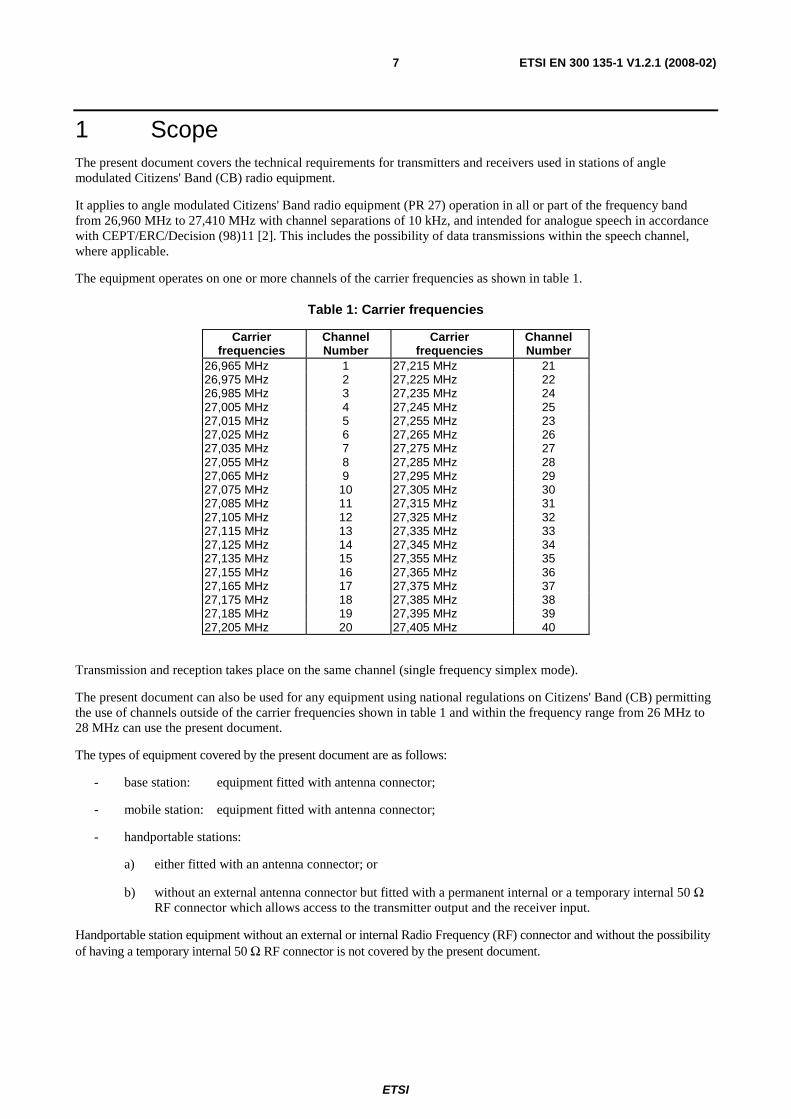
The equipment operates on one or more channels of the carrier frequencies as shown in table 1.
Table 1: Carrier frequencies
Carrier frequencies
Channel Number
Carrier frequencies
Channel Number
26,965 MHz 1 27,215 MHz 21 26,975 MHz 2 27,225 MHz 22 26,985 MHz 3 27,235 MHz 24 27,005 MHz 4 27,245 MHz 25 27,015 MHz 5 27,255 MHz 23 27,025 MHz 6 27,265 MHz 26 27,035 MHz 7 27,275 MHz 27 27,055 MHz 8 27,285 MHz 28 27,065 MHz 9 27,295 MHz 29 27,075 MHz 10 27,305 MHz 30 27,085 MHz 11 27,315 MHz 31 27,105 MHz 12 27,325 MHz 32 27,115 MHz 13 27,335 MHz 33 27,125 MHz 14 27,345 MHz 34 27,135 MHz 15 27,355 MHz 35 27,155 MHz 16 27,365 MHz 36 27,165 MHz 17 27,375 MHz 37 27,175 MHz 18 27,385 MHz 38 27,185 MHz 19 27,395 MHz 39 27,205 MHz 20 27,405 MHz 40
Transmission and reception takes place on the same channel (single frequency simplex mode).
The present document can also be used for any equipment using national regulations on Citizens' Band (CB) permitting the use of channels outside of the carrier frequencies shown in table 1 and within the frequency range from 26 MHz to 28 MHz can use the present document.
The types of equipment covered by the present document are as follows:
- base station: equipment fitted with antenna connector;
- mobile station: equipment fitted with antenna connector;
- handportable stations:
a) either fitted with an antenna connector; or
b) without an external antenna connector but fitted with a permanent internal or a temporary internal 50 Ω RF connector which allows access to the transmitter output and the receiver input.
Handportable station equipment without an external or internal Radio Frequency (RF) connector and without the possibility of having a temporary internal 50 Ω RF connector is not covered by the present document.
ETSI
ETSI EN 300 135-1 V1.2.1 (2008-02) 8
2 References References are either specific (identified by date of publication and/or edition number or version number) or non-specific.
• For a specific reference, subsequent revisions do not apply.
• Non-specific reference may be made only to a complete document or a part thereof and only in the following cases:
- if it is accepted that it will be possible to use all future changes of the referenced document for the purposes of the referring document;
- for informative references.
Referenced documents which are not found to be publicly available in the expected location might be found at http://docbox.etsi.org/Reference.
For online referenced documents, information sufficient to identify and locate the source shall be provided. Preferably, the primary source of the referenced document should be cited, in order to ensure traceability. Furthermore, the reference should, as far as possible, remain valid for the expected life of the document. The reference shall include the method of access to the referenced document and the full network address, with the same punctuation and use of upper case and lower case letters.
NOTE: While any hyperlinks included in this clause were valid at the time of publication ETSI cannot guarantee their long term validity.
2.1 Normative references The following referenced documents are indispensable for the application of the present document. For dated references, only the edition cited applies. For non-specific references, the latest edition of the referenced document (including any amendments) applies.
[1] ETSI TR 100 028 (V1.4.1) (all parts): "Electromagnetic compatibility and Radio spectrum Matters (ERM); Uncertainties in the measurement of mobile radio equipment characteristics".
2.2 Informative references [2] CEPT/ERC/DEC(98)11: "ERC Decision of 23 November 1998 on the harmonised frequency band
to be designated for CEPT PR 27 radio equipment and on the implementation of the technical standard for this equipment".
3 Definitions, symbols and abbreviations
3.1 Definitions For the purposes of the present document, the following terms and definitions apply:
angle modulation: modulation with an audio pre-emphasis characteristic for the FM transmitter and an audio de-emphasis characteristic for the receiver
base station: equipment fitted with an antenna socket, for use with an external antenna, and intended for use in a fixed location
handportable station: equipment either fitted with an antenna connector or an integral antenna, or both, normally used on a stand-alone basis, to be carried on a person or held in the hand
ETSI
ETSI EN 300 135-1 V1.2.1 (2008-02) 9
integral antenna: antenna designed as a fixed part of the equipment, without the use of an external connector and as such which can not be disconnected from the equipment by the user
NOTE: An integral antenna may be fitted internally or externally.
mobile station: mobile equipment fitted with an antenna connector, for use with an external antenna, normally used in a vehicle or as a transportable station
3.2 Symbols For the purposes of the present document, the following symbols apply:
Eo reference field strength, (see annex A) ptt push-to-talk RBW Resolution BandWidth Ro reference distance, (see annex A)
3.3 Abbreviations For the purposes of the present document, the following abbreviations apply:
CB Citizens' Band FM Frequency Modulation IF Intermediate Frequency RF Radio Frequency Tmax maximum Temperature
Tmin minimum Temperature
Tx Transmitter Vmax maximum Voltage
Vmin minimum Voltage
4 General
4.1 Presentation of equipment for testing purposes Each equipment to be tested submitted for testing shall fulfil the requirements of the present document on all frequencies over which it is intended to operate.
The provider or manufacturer shall declare the frequency ranges, the range of operating conditions and power requirements as applicable, to establish the appropriate test conditions.
Additionally, technical documentation and operating manuals, sufficient to make the test, shall be supplied.
4.1.1 Choice of model for testing
The provider or manufacturer shall provide one or more samples of the equipment, as appropriate for testing.
Stand alone equipment shall be complete with any ancillary equipment needed for testing.
If an equipment has several optional features, considered not to affect the RF parameters then the tests need only to be performed on the equipment configured with that combination of features considered to be the most complex.
Where practicable, equipment to be tested shall provide a 50 Ω connector for conducted RF power level measurements.
In the case of integral antenna equipment, if the equipment does not have an internal permanent 50 Ω connector then it is permissible to supply a second sample of the equipment with a temporary antenna connector fitted to facilitate testing.
ETSI
ETSI EN 300 135-1 V1.2.1 (2008-02) 10
The performance of the equipment to be tested shall be representative of the performance of the corresponding production model. Tests shall be carried out on the highest and lowest channel within the switching range of the equipment and on a channel near the middle of the switching range. The switching range of the receiver and transmitter shall be declared by the manufacturer. The switching range is the maximum frequency range over which the receiver or the transmitter can be operated without reprogramming or realignment. In the case of equipment fitted with one channel only, all tests are carried out on that channel. In the case of equipment fitted with two channels, all tests are carried out on both channels.
4.1.1.1 Auxiliary test equipment
Setting up instructions and other product information shall accompany the equipment to be tested.
4.1.1.2 Declarations by the provider
The provider or manufacturer shall declare the necessary information of the equipment with respect to all technical requirements set by the present document.
In the case of hand portable equipment without a 50 Ω external antenna connector, see clause 4.2.
4.2 Testing of equipment that does not have an external 50 Ω RF connector (integral antenna equipment)
Where equipment has an internal 50 Ω connector it shall be permitted to perform the tests at this connector.
Equipment may also have a temporary internal 50 Ω connector installed for the purposes of testing.
No connection shall be made to any internal permanent or temporary antenna connector during the performance of radiated emissions measurements, unless such action forms an essential part of the normal intended operation of the equipment, as declared by the manufacturer.
4.3 Mechanical and electrical design
4.3.1 General
The equipment submitted by the manufacturer or his representative, shall be designed, constructed and manufactured in accordance with sound engineering practice, and with the aim to minimize harmful interference to other equipment and services.
4.3.2 Controls
Those controls which if maladjusted might increase the interfering potentialities of the equipment shall not be accessible to the user.
4.3.3 Push-to-talk (ptt) and voice activated switch
Switching between the transmit and receive mode of operation shall only be possible by means of a non-locking ptt switch or by means of a non-locking voice activated switch. If a voice activated switch is used, it shall not respond to ambient acoustic noise.
4.3.4 Combination with other equipment
The equipment shall not be combined with any other form of transmitting or receiving equipment which can produce unwanted modulation of the transmitter. The equipment shall not be provided with any terminals or other connection points, internal or external, for modulating sources other than those required for either a separate or a built-in microphone, or for selective calling or data transmission devices.
ETSI
ETSI EN 300 135-1 V1.2.1 (2008-02) 11
Terminals or other connecting points are permitted for the connection of external devices that shall not modulate the transmitters (e.g. a voice synthesizer device to give an aural indication of channel).
4.4 Declaration of conformity The declaration of conformity shall include the information about the applicable national regulation under which the equipment can be operated if the provider uses the present document for other carrier frequencies than PR 27 (see clause 1, table 1).
5 Test conditions, power sources and ambient temperatures
5.1 Normal and extreme test conditions Testing shall be performed under normal test conditions, and also, where stated, under extreme test conditions.
The test conditions and procedures shall be as specified in clauses 5.2 to 5.5.
5.2 Test power source During testing the power source of the equipment shall be replaced by a test power source capable of producing normal and extreme test voltages as specified in clauses 5.3.2 and 5.4.2. The internal impedance of the test power source shall be low enough for its effect on the test results to be negligible. For the purpose of tests, the voltage of the power source shall be measured at the input terminals of the equipment.
For battery operated equipment the battery shall be removed and the test power source shall be applied as close to the battery terminals as practicable.
During tests of DC powered equipment the power source voltages shall be maintained within a tolerance of < ±1 % relative to the voltage at the beginning of each test. The value of this tolerance is critical for power measurements; using a smaller tolerance will provide better measurement uncertainty values.
5.3 Normal test conditions
5.3.1 Normal temperature and humidity
The normal temperature and humidity conditions for tests shall be any convenient combination of temperature and humidity within the following ranges:
temperature: +15 °C to +35 °C;
relative humidity: 20 % to 75 %.
When it is impracticable to carry out the tests under these conditions, a note to this effect, stating the ambient temperature and relative humidity during the tests, shall be added to the test report.
5.3.2 Normal test power source
5.3.2.1 Mains voltage
The normal test voltage for equipment to be connected to the mains shall be the nominal mains voltage. For the purpose of the present document, the nominal voltage shall be the declared voltage or any of the declared voltages for which the equipment was designed.
The frequency of the test power source corresponding to the ac mains shall be between 49 Hz and 51 Hz.
ETSI
ETSI EN 300 135-1 V1.2.1 (2008-02) 12
5.3.2.2 Regulated lead-acid battery power sources used on vehicles
When the radio equipment is intended for operation from the usual types of regulated lead-acid battery power source used on vehicles the normal test voltage shall be 1,1 times the nominal voltage of the battery (e.g. for nominal voltages of 12 V and 24 V, these are 13,2 V and 26,4 V respectively).
5.3.2.3 Other power sources
For operation from other power sources or types of battery (primary or secondary), the normal test voltage shall be that declared by the equipment manufacturer.
5.4 Extreme test conditions
5.4.1 Extreme temperatures
For tests at extreme temperatures, measurements shall be made in accordance with the procedures specified in clause 5.5, at the upper and lower temperatures of one of the following two ranges:
• -10 °C to +55 °C; All mobile and handportable equipment. Base stations for outdoor/uncontrolled climate conditions.
• 0 °C to +40 °C; Base stations for indoor/controlled climate conditions.
In the case of base stations equipment, the manufacturer shall declare which conditions the equipment is intended to be installed in.
5.4.2 Extreme test source voltages
5.4.2.1 Mains voltage
The extreme test voltage for equipment to be connected to an ac mains source shall be the nominal mains voltage ±10 %.
5.4.2.2 Regulated lead-acid battery power sources used on vehicles
When the equipment is intended for operation from the usual types of regulated lead-acid battery power sources used on vehicles, the extreme test voltages shall be 1,3 and 0,9 times the nominal voltage of the battery (e.g. for a nominal voltage of 12 V, these are 10,8 V and 15,6 V respectively and for a nominal voltage of 24 V, these are 21,6 V and 31,2 V respectively).
5.4.2.3 Power sources using other types of batteries
The lower extreme test voltages for equipment with power sources using batteries shall be as follows:
- for the nickel metal-hydride, leclanché or lithium type: 0,85 times the nominal battery voltage;
- for the mercury or nickel-cadmium type: 0,9 times the nominal battery voltage.
No upper extreme test voltages apply.
In the case where no upper extreme test voltage the nominal voltage is applicable, the corresponding four extreme test conditions are:
• Vmin/Tmin, Vmin/Tmax;
• (Vmax = nominal)/Tmin, (Vmax = nominal)/Tmax.
ETSI
ETSI EN 300 135-1 V1.2.1 (2008-02) 13
5.4.2.4 Other power sources
For equipment using other power sources, or capable of being operated from a variety of power sources, the extreme test voltages shall be those declared by the equipment manufacturer.
5.5 Procedure for tests at extreme temperatures Before measurements are made the equipment shall have reached thermal balance in the test chamber. The equipment shall be switched off during the temperature stabilizing period.
In the case of equipment containing temperature stabilization circuits designed to operate continuously, the temperature stabilization circuits may be switched on for 15 minutes after thermal balance has been obtained, and the equipment shall then meet the specified requirements. For such equipment the manufacturer shall provide for the power source circuit feeding the crystal oven to be independent of the power source for the rest of the equipment.
If the thermal balance is not checked by measurements, a temperature stabilizing period of at least one hour, or a longer period as may be decided by the testing laboratory, shall be allowed. The sequence of measurements shall be chosen, and the humidity content in the test chamber shall be controlled so that excessive condensation does not occur.
6 General test conditions
6.1 Arrangements for test signals applied to the receiver input Sources of test signals for application to the receiver input shall be connected in such a way that the impedance presented to the receiver input is 50 Ω.
This requirement shall be met irrespective of whether one or more signals are supplied to the receiver simultaneously.
The levels of the test signals shall be expressed in terms of the e.m.f. at the receiver input terminals.
The effects of any intermodulation products and noise produced in the signal generators should be negligible. The test generators shall be substantially free from static amplitude modulation.
6.2 Receiver mute or squelch facility If the receiver is equipped with a mute or squelch circuit, this shall be made inoperative for the duration of the tests.
6.3 Receiver rated audio output power The rated audio output power shall be the maximum power, declared by the manufacturer, for which all the requirements of the present document are met. With normal test modulation (clause 6.4), the audio power shall be measured in a resistive load, simulating the load with which the receiver normally operates. The value of this load shall be declared by the manufacturer.
6.4 Normal test modulation For normal test modulation, the modulation frequency shall be 1 kHz and the resulting frequency deviation shall be ±1,2 kHz.
6.5 Artificial antenna Tests on the transmitter shall be carried out with a non-reactive non-radiating load of 50 Ω connected to the antenna terminals.
ETSI
ETSI EN 300 135-1 V1.2.1 (2008-02) 14
Tests on the transmitter requiring the use of the test fixture shall be carried out with a 50 Ω non-reactive non-radiating load connected to the test fixture.
6.6 Test fixture In the case of equipment intended for use with an integral antenna, the manufacturer may be required to supply a test fixture, suitable to allow relative measurements to be made on the submitted sample.
The test fixture shall provide means of making external connection to the audio frequency input and radio frequency output and of replacing the power source by external power supplies.
The test fixture shall provide a 50 Ω radio frequency terminal at the working frequencies of the equipment.
The performance characteristics of this test fixture under normal and extreme conditions are subject to the approval of the test laboratory.
The characteristics of interest to the test laboratory will be that:
a) the coupling loss shall not be greater than 30 dB;
b) the variation of coupling loss with frequency shall not cause errors exceeding 2 dB in measurements using the test fixture;
c) the coupling device shall not include any non-linear elements; the test laboratory may provide its own test fixture.
6.7 Arrangement for test signals at the input of the transmitter The transmitter audio frequency modulation signal shall be supplied by a generator applied at the connections of the microphone insert, unless otherwise stated.
6.8 Test site and general arrangements for radiated measurements
Detailed descriptions of the radiated measurement arrangements are included in annex A.
7 Method of measurement for transmitter parameters
7.1 Frequency error For equipment that can be measured for frequency error, under this clause, the manufacturer may choose to omit this test if the adjacent channel power is measured under extreme test conditions in clause 7.4.2.
7.1.1 Definition
The frequency error of the transmitter is the difference between the measured carrier frequency and its nominal value.
7.1.2 Method of measurement
The carrier frequency shall be measured in the absence of modulation, with the transmitter connected to an artificial antenna (clause 6.5). Equipment with an integral antenna shall be placed in the test fixture (clause 6.6) connected to the artificial antenna (clause 6.5). The measurement shall be made under normal test conditions (clause 5.3) and repeated under extreme test conditions (clauses 5.4.1 and 5.4.2 applied simultaneously).
ETSI
ETSI EN 300 135-1 V1.2.1 (2008-02) 15
7.1.3 Limit
The frequency error shall not exceed 0,6 kHz.
7.2 Transmitter carrier power
7.2.1 Definition
The transmitter carrier power is the mean power delivered to the artificial antenna during a radio frequency cycle, or in the case of equipment with integral antenna the effective radiated power in the direction of maximum field strength under the specified conditions of measurement (clause 6.8) in the absence of modulation.
7.2.2 Method of measurement
The measurements shall be made under normal test conditions (clause 5.3) and extreme test conditions (clauses 5.4.1 and 5.4.2 applied simultaneously).
7.2.2.1 Method of measurement (for equipment other than equipment with integral antenna only)
The transmitter shall be connected to an artificial antenna (clause 6.5), and the power delivered to this artificial antenna shall be measured.
7.2.2.2 Method of measurement for equipment with integral antenna
On a test site selected from annex A the equipment shall be placed on the support in the following position:
a) for equipment with an internal antenna, it shall stand so that the axis of the equipment which in its normal use is closest to the vertical, shall be vertical;
b) for equipment with a rigid external antennas, the antenna shall be vertical;
c) for equipment with a non-rigid external antenna, the antenna shall be extended vertically upwards by a non-conducting support.
The test antenna shall be orientated for vertical polarization and the length of the test antenna shall be chosen to correspond to the frequency of the transmitter. The output of the test antenna shall be connected to a measuring receiver. The transmitter shall be switched on without modulation and the measuring receiver shall be tuned to the frequency of the transmitter under test. The test antenna shall be raised and lowered through the specified range of height until a maximum signal level is detected by the measuring receiver.
The transmitter shall then be rotated through 360o in the horizontal plane until the maximum signal level is detected by the measuring receiver.
The maximum signal level detected by the measuring receiver shall be noted.
The transmitter shall be replaced by a substitution antenna as defined in clause A.2.3.
The substitution antenna shall be orientated for vertical polarization and the length of the substitution antenna shall be adjusted to correspond to the frequency of the transmitter.
The substitution antenna shall be connected to a calibrated signal generator.
The input attenuator setting of the measuring receiver shall be adjusted in order to increase the sensitivity of the measuring receiver.
The test antenna shall be raised and lowered through the specified range of height to ensure that the maximum signal is received.
ETSI
ETSI EN 300 135-1 V1.2.1 (2008-02) 16
The input signal to the substitution antenna shall be adjusted to the level that produces a level detected by the measuring receiver, that is equal to the level noted while the transmitter radiated power was measured, corrected for the change of input attenuator setting of the measuring receiver.
The measurement shall be repeated with the test antenna and the substitution antenna orientated for horizontal polarization.
The measure of the effective radiated power is the larger of the two power levels recorded, at the input to the substitution antenna, corrected for gain of the antenna if necessary.
7.2.3 Limits
The transmitter carrier power, or the effective radiated power of an equipment with an integral antenna, shall not exceed 4 watts.
7.3 Maximum permissible frequency deviation
7.3.1 Definition
The maximum frequency deviation is the maximum difference between the instantaneous frequency of the modulated radio frequency signal and the carrier frequency in the absence of modulation.
7.3.2 Method of measurement
The frequency deviation shall be measured at the output of the transmitter connected via a 50 Ω power attenuator, to a deviation meter capable of measuring the maximum deviation, including that due to any harmonics and intermodulation products which may be generated in the transmitter.
The modulation frequency of the test signal shall be varied between the lowest frequency considered to be appropriate, and 10 kHz. The level of this test signal shall be 20 dB above the level required to give a frequency deviation of 1,2 kHz at an audio frequency of 1 250 Hz.
The measurements shall be made under normal test conditions (clause 5.3).
7.3.3 Limit
The maximum permissible frequency deviation shall be ±2 kHz.
7.4 Adjacent channel power
7.4.1 Definition
The adjacent channel power is that part of the total output power of a transmitter, modulated under defined conditions, which falls within a specified bandwidth centered on the nominal frequency of either of the adjacent channels. This power is the sum of the mean power produced by the modulation process and by residual modulation caused by hum and noise of the transmitter.
7.4.2 Method of measurement
The adjacent channel power shall be measured with a power measuring receiver (consists either of a spectrum analyser or mixer, an IF filter, an oscillator, an amplifier, a variable attenuator and an rms value indicator as indicated in annex B) which conforms with the requirements given in annex B and is referred to in this clause as the "receiver".
a) The transmitter shall be operated at the carrier power measured in clause 7.2 under normal test conditions (clause 5.3). The output of the transmitter shall be linked to the input of the "receiver" by a connecting device such that the impedance presented to the transmitter is 50 Ω and the level at the "receiver" input is appropriate. For equipment with an integral antenna the connecting device is a test fixture as described in clause 6.6.
ETSI
ETSI EN 300 135-1 V1.2.1 (2008-02) 17
b) With the transmitter unmodulated, the tuning of the "receiver" shall be adjusted so that a maximum response is obtained. This is the 0 dB reference point. The "receiver" variable attenuator setting and the reading of the rms value indicator shall be recorded.
c) The tuning of the "receiver" shall be adjusted away from the carrier so that the "receiver" - 6 dB response nearest to the transmitter carrier frequency is located at a displacement of 5,75 kHz from the nominal carrier frequency.
d) The transmitter shall be modulated by a test signal of 1 250 Hz at a level which is 20 dB higher than that required to produce a deviation of ±1,2 kHz.
e) The "receiver" variable attenuator shall be adjusted to obtain the same reading as in step b) or a known relation to it.
f) The ratio of adjacent channel power to carrier power is the difference between the attenuator settings in steps b) and e), corrected for any differences in the reading of the rms value indicator.
g) The measurement shall be repeated with the "receiver" tuned to the other side of the carrier.
The measurements shall be made under normal test conditions (clause 5.3) and may also be performed under extreme conditions. The manufacturer may choose to omit the test specified in clause 7.1.2 if the adjacent channel power is also measured under extreme test conditions.
7.4.3 Limit
The adjacent channel power shall not exceed a value of 20 microwatts.
7.5 Unwanted emissions in the spurious domain
7.5.1 Definition
Spurious emissions are emissions at frequencies other than those of the carrier and sidebands associated with normal test modulation. The level of spurious emissions shall be measured as:
a) power level in a specified load (conducted spurious emission); and
b) their effective radiated power when radiated by the cabinet and structure of the equipment (cabinet radiation); or
c) their effective radiated power when radiated by the cabinet and the integral antenna, in the case of handportable equipment fitted with such an antenna and no external RF connector.
7.5.2 Method of measurement
7.5.2.1 Method of measuring the power level in a specified load
The transmitter shall be connected to a 50 Ω power attenuator. The output of the power attenuator shall be connected to a measuring receiver.
The transmitter shall be switched on without modulation, and the measuring receiver shall be tuned over the frequency range 9 kHz to 2 GHz.
At each frequency at which a spurious component is detected, the power level shall be recorded as the conducted spurious emission level delivered into the specified load, except for the channel on which the transmitter is intended to operate and the adjacent channels.
The measurements shall be repeated with the transmitter on stand-by.
ETSI
ETSI EN 300 135-1 V1.2.1 (2008-02) 18
7.5.2.2 Method of measuring the effective radiated power
On a test site, selected from annex A, the equipment shall be placed at the specified height on the appropriate support and in the position closest to normal use as declared by the manufacturer.
The transmitter antenna connector shall be connected to an artificial antenna, clause 6.5.
The test antenna shall be orientated for vertical polarization and the length of the test antenna shall be chosen to correspond to the instantaneous frequency of the measuring receiver.
The output of the test antenna shall be connected to a measuring receiver. The transmitter shall be switched on without modulation, and the measuring receiver shall be tuned over the frequency range 25 MHz to 2 GHz, except for the channel on which the transmitter is intended to operate and its adjacent channels.
At each frequency at which a spurious component is detected, the test antenna shall be raised and lowered through the specified range of heights until the maximum signal level is detected on the measuring receiver.
The transmitter shall then be rotated through 360o in the horizontal plane, until the maximum signal level is detected by the measuring receiver.
The maximum signal level detected by the measuring receiver shall be noted.
The transmitter shall be replaced by a substitution antenna as defined in clause A.2.3.
The substitution antenna shall be orientated for vertical polarization and the length of the substitution antenna shall be adjusted to correspond to the frequency of the spurious component detected.
The substitution antenna shall be connected to a calibrated signal generator.
The frequency of the calibrated signal generator shall be set to the frequency of the spurious component detected.
The input attenuator setting of the measuring receiver shall be adjusted in order to increase the sensitivity of the measuring receiver, if necessary.
The test antenna shall be raised and lowered through the specified range of heights to ensure that the maximum signal is received.
The input signal to the substitution antenna shall be adjusted to the level that produces a level detected by the measuring receiver, that is equal to the level noted while the spurious component was measured, corrected for the change of input attenuator setting of the measuring receiver.
The input level to the substitution antenna shall be recorded as power level, corrected for the change of input attenuator setting of the measuring receiver.
The measurement shall be repeated with the test antenna and the substitution antenna orientated for horizontal polarization.
The measure of the effective radiated power of the spurious components is the larger of the two power levels recorded for each spurious component at the input to the substitution antenna, corrected for the gain of the antenna if necessary.
The measurements shall be repeated with the transmitter on stand-by.
7.5.2.3 Method of measuring the effective radiated power
The measurement shall be performed according to clause 7.5.2.2, except that the transmitter output shall be connected to the integral antenna and not to an artificial antenna.
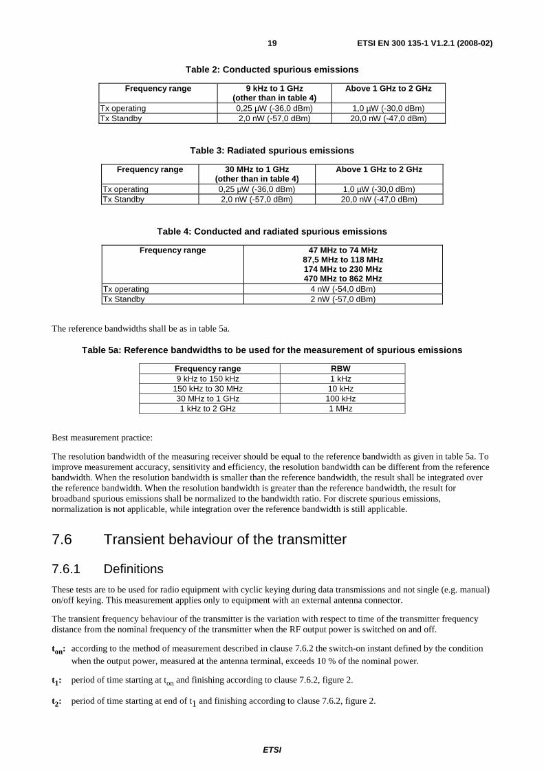
7.5.3 Limits
The power of any spurious emission, occurring more than 2,5 × channel bandwidth from the centre of the channel on which the transmitter is intended to operate, shall not exceed the values given in tables 2, 3 and 4.
ETSI
ETSI EN 300 135-1 V1.2.1 (2008-02) 19
Table 2: Conducted spurious emissions
Frequency range 9 kHz to 1 GHz (other than in table 4)
Above 1 GHz to 2 GHz
Tx operating 0,25 µW (-36,0 dBm) 1,0 µW (-30,0 dBm) Tx Standby 2,0 nW (-57,0 dBm) 20,0 nW (-47,0 dBm)
Table 3: Radiated spurious emissions
Frequency range 30 MHz to 1 GHz (other than in table 4)
Above 1 GHz to 2 GHz
Tx operating 0,25 µW (-36,0 dBm) 1,0 µW (-30,0 dBm) Tx Standby 2,0 nW (-57,0 dBm) 20,0 nW (-47,0 dBm)
Table 4: Conducted and radiated spurious emissions
Frequency range 47 MHz to 74 MHz 87,5 MHz to 118 MHz 174 MHz to 230 MHz 470 MHz to 862 MHz
Tx operating 4 nW (-54,0 dBm) Tx Standby 2 nW (-57,0 dBm)
The reference bandwidths shall be as in table 5a.
Table 5a: Reference bandwidths to be used for the measurement of spurious emissions
Frequency range RBW 9 kHz to 150 kHz 1 kHz
150 kHz to 30 MHz 10 kHz 30 MHz to 1 GHz 100 kHz 1 kHz to 2 GHz 1 MHz
Best measurement practice:
The resolution bandwidth of the measuring receiver should be equal to the reference bandwidth as given in table 5a. To improve measurement accuracy, sensitivity and efficiency, the resolution bandwidth can be different from the reference bandwidth. When the resolution bandwidth is smaller than the reference bandwidth, the result shall be integrated over the reference bandwidth. When the resolution bandwidth is greater than the reference bandwidth, the result for broadband spurious emissions shall be normalized to the bandwidth ratio. For discrete spurious emissions, normalization is not applicable, while integration over the reference bandwidth is still applicable.
7.6 Transient behaviour of the transmitter
7.6.1 Definitions
These tests are to be used for radio equipment with cyclic keying during data transmissions and not single (e.g. manual) on/off keying. This measurement applies only to equipment with an external antenna connector.
The transient frequency behaviour of the transmitter is the variation with respect to time of the transmitter frequency distance from the nominal frequency of the transmitter when the RF output power is switched on and off.
ton: according to the method of measurement described in clause 7.6.2 the switch-on instant defined by the condition when the output power, measured at the antenna terminal, exceeds 10 % of the nominal power.
t1: period of time starting at ton and finishing according to clause 7.6.2, figure 2.
t2: period of time starting at end of t1 and finishing according to clause 7.6.2, figure 2.
ETSI
ETSI EN 300 135-1 V1.2.1 (2008-02) 20
toff: switch-off instant defined by the condition when the output power falls below 10 % of the nominal power.
t3: period of time finishing at toff and starting according to clause 7.6.2, figure 2.
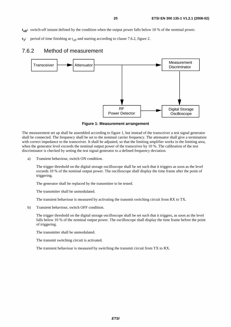
7.6.2 Method of measurement
Transceiver AttenuatorMeasurement Discriminator
Digital Storage Oscilloscope
RF Power Detector
Figure 1: Measurement arrangement
The measurement set up shall be assembled according to figure 1, but instead of the transceiver a test signal generator shall be connected. The frequency shall be set to the nominal carrier frequency. The attenuator shall give a termination with correct impedance to the transceiver. It shall be adjusted, so that the limiting amplifier works in the limiting area, when the generator level exceeds the nominal output power of the transceiver by 10 %. The calibration of the test discriminator is checked by setting the test signal generator to a defined frequency deviation.
a) Transient behaviour, switch ON condition.
The trigger threshold on the digital storage oscilloscope shall be set such that it triggers as soon as the level exceeds 10 % of the nominal output power. The oscilloscope shall display the time frame after the point of triggering.
The generator shall be replaced by the transmitter to be tested.
The transmitter shall be unmodulated.
The transient behaviour is measured by activating the transmit switching circuit from RX to TX.
b) Transient behaviour, switch OFF condition.
The trigger threshold on the digital storage oscilloscope shall be set such that it triggers, as soon as the level falls below 10 % of the nominal output power. The oscilloscope shall display the time frame before the point of triggering.
The transmitter shall be unmodulated.
The transmit switching circuit is activated.
The transient behaviour is measured by switching the transmit circuit from TX to RX.
ETSI
ETSI EN 300 135-1 V1.2.1 (2008-02) 21
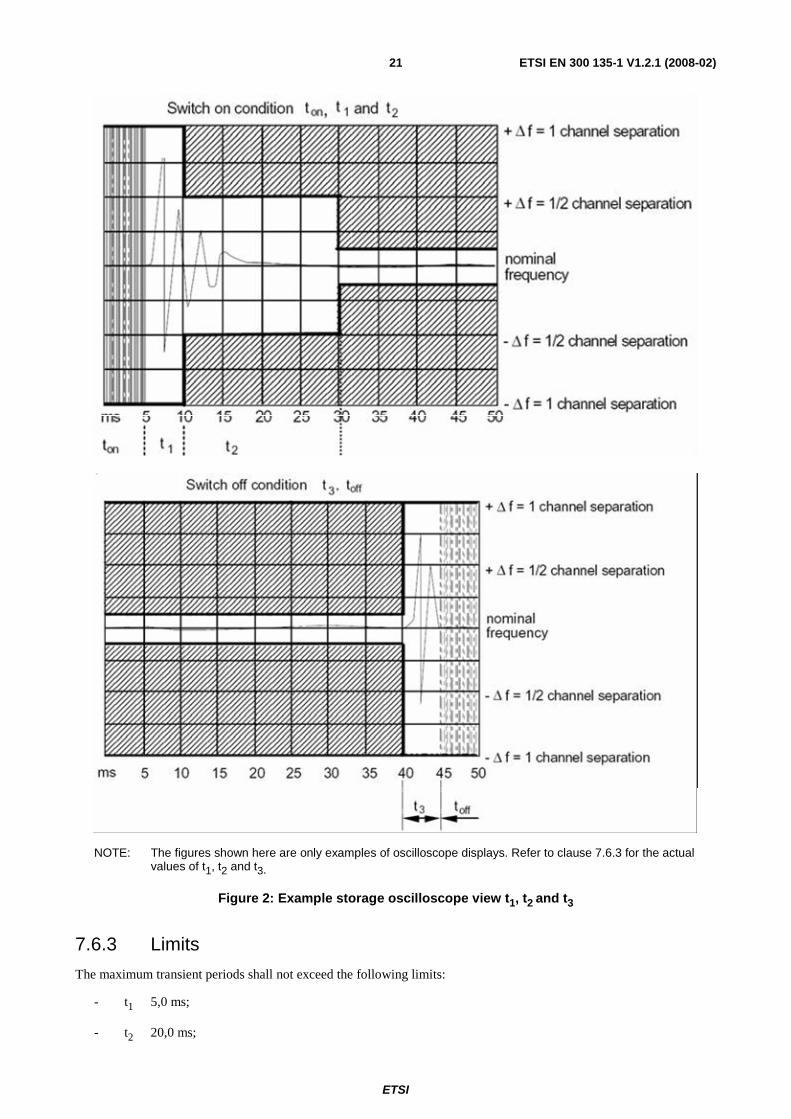
NOTE: The figures shown here are only examples of oscilloscope displays. Refer to clause 7.6.3 for the actual values of t1, t2 and t3.
Figure 2: Example storage oscilloscope view t1, t2 and t3
7.6.3 Limits
The maximum transient periods shall not exceed the following limits:
- t1 5,0 ms;
- t2 20,0 ms;
ETSI
ETSI EN 300 135-1 V1.2.1 (2008-02) 22
- t3 5,0 ms.
During the periods t1 and t3 the frequency difference shall not exceed the value of 1 channel separation.
During the period t2 the frequency difference shall not exceed the value of half a channel separation.
In the case of handportable stations, the frequency deviation during t1 and t3 may be greater than one channel. The
corresponding plot of frequency versus time during t1 and t3 shall be recorded in the test report.
8 Methods of measurement for receiver parameters
8.1 Spurious radiations
8.1.1 Definition
Spurious radiations from the receiver are components at any frequency, radiated by the equipment and antenna.
The level of spurious radiations shall be measured by:
a) their power level in a specified load (conducted spurious emission); and
b) their effective radiated power when radiated by the cabinet and structure of the equipment (cabinet radiation); or
c) their effective radiated power when radiated by the cabinet and the integral antenna, in the case of handportable equipment fitted with such an antenna and no external RF connector.
8.1.2 Method of measurement
8.1.2.1 Method of measuring the power level in a specified load
The receiver shall be connected to a 50 Ω attenuator. The output of the attenuator shall be connected to a measuring receiver. The receiver shall be switched on, and the measuring receiver shall be tuned over the frequency range 9 kHz to 2 GHz.
At each frequency at which a spurious component is detected, the power level shall be recorded as the spurious level delivered into the specified load.
8.1.2.2 Method of measuring the effective radiated power
On a test site, selected from annex A, the equipment shall be placed at the specified height on the appropriate support and in the position closest to normal use as declared by the manufacturer. The receiver antenna connector shall be connected to an artificial antenna, clause 6.5.
The test antenna shall be orientated for vertical polarization and the length of the test antenna shall be chosen to correspond to the instant frequency of the measuring receiver. The output of the test antenna shall be connected to a measuring receiver. The receiver shall be switched on and the measuring receiver shall be tuned over the frequency range 25 MHz to 2 GHz. At each frequency at which a spurious component is detected, the test antenna shall be raised and lowered through the specified range of height until a maximum signal level is detected by the measuring receiver. The receiver shall then be rotated through 360o in the horizontal plane until the maximum signal level is detected by the measuring receiver. The maximum signal level detected by the measuring receiver shall be noted.
The receiver shall be replaced by a substitution antenna as defined in clause A.2.3. The substitution antenna shall be orientated for vertical polarization and the length of the substitution antenna shall be adjusted to correspond to the frequency of the spurious component detected. The substitution antenna shall be connected to a calibrated signal generator. The frequency of the calibrated signal generator shall be set to the frequency of the spurious component detected.
ETSI
ETSI EN 300 135-1 V1.2.1 (2008-02) 23
The input attenuator setting of the measuring receiver shall be adjusted in order to increase the sensitivity of the measuring receiver, if necessary. The test antenna shall be raised and lowered through the specified range of height to ensure that the maximum signal is received. The input signal to the substitution antenna shall be adjusted to the level that produces a level noted while the spurious component was measured, corrected for the change of input attenuator setting of the measuring receiver. The input level to the substitution antenna shall be recorded as power level, corrected for the change of input attenuator setting of the measuring receiver.
The measurement shall be repeated with the test antenna and the substitution antenna orientated for horizontal polarization.
The measure of the effective radiated power of the spurious components is the larger of the two power levels recorded for each spurious component at the input to the substitution antenna, corrected for the gain of the antenna if necessary.
8.1.2.3 Method of measuring the effective radiated power
The measurement shall be performed according to clause 8.1.2.2, except that the receiver input shall be connected to the integral antenna and not to an artificial antenna.
8.1.3 Limits
The power of any spurious radiations shall not exceed the values given in tables 5b and 6.
Table 5b: Conducted components
Frequency range 9 kHz to 1 GHz Above 1 GHz to 2 GHz Limit 2,0 nW (-57,0 dBm) 20,0 nW (-47,0 dBm)
Table 6: Radiated components
Frequency range 30 MHz to 1 GHz Above 1 GHz to 2 GHz Limit 2,0 nW (-57,0 dBm) 20,0 nW (-47,0 dBm)
The reference bandwidths from table 7 shall be used.
Table 7: Reference bandwidths to be used for the measurement of spurious radiations
Frequency range RBW 9 kHz to 150 kHz 1 kHz
150 kHz to 30 MHz 10 kHz 30 MHz to 1 GHz 100 kHz 1 GHz to 2 GHz 1 MHz
9 Measurement uncertainty The interpretation of the results recorded in the test report for the measurements described in the present document shall be as follows:
- the measured value related to the corresponding limit shall be used to decide whether an equipment meets the requirements of the present document;
- the value of the measurement uncertainty for the measurement of each parameter shall be separately included in the test report;
- the value of the measurement uncertainty, for each measurement, shall comply with the figures in table 8.
ETSI
ETSI EN 300 135-1 V1.2.1 (2008-02) 24
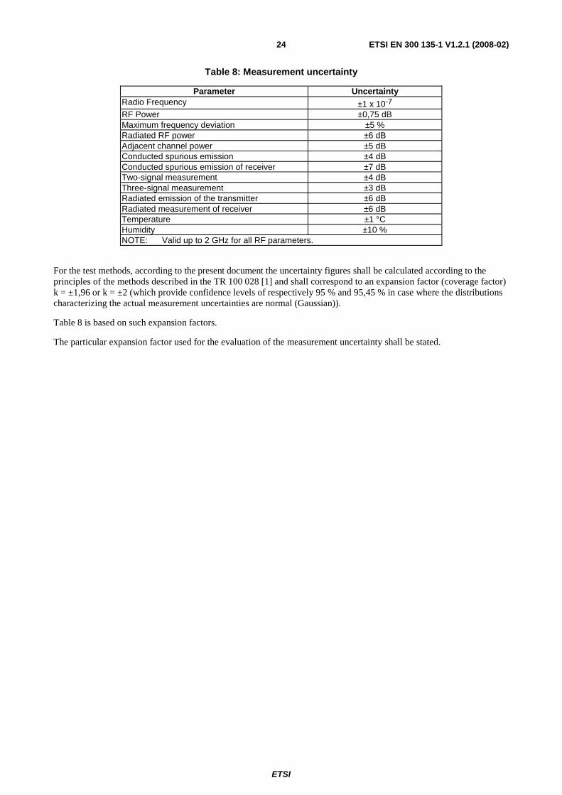
Table 8: Measurement uncertainty
Parameter Uncertainty Radio Frequency ±1 x 10⁻⁷ RF Power ±0,75 dB Maximum frequency deviation ±5 % Radiated RF power ±6 dB Adjacent channel power ±5 dB Conducted spurious emission ±4 dB Conducted spurious emission of receiver ±7 dB Two-signal measurement ±4 dB Three-signal measurement ±3 dB Radiated emission of the transmitter ±6 dB Radiated measurement of receiver ±6 dB Temperature ±1 °C Humidity ±10 % NOTE: Valid up to 2 GHz for all RF parameters.
For the test methods, according to the present document the uncertainty figures shall be calculated according to the principles of the methods described in the TR 100 028 [1] and shall correspond to an expansion factor (coverage factor) k = ±1,96 or k = ±2 (which provide confidence levels of respectively 95 % and 95,45 % in case where the distributions characterizing the actual measurement uncertainties are normal (Gaussian)).
Table 8 is based on such expansion factors.
The particular expansion factor used for the evaluation of the measurement uncertainty shall be stated.
ETSI
ETSI EN 300 135-1 V1.2.1 (2008-02) 25
Annex A (normative): Radiated measurement
A.1 Test sites and general arrangements for measurements involving the use of radiated fields
A.1.1 Outdoor test site The outdoor test site shall be on a reasonably level surface or ground. At one point on the site, a ground plane of at least 5 m diameter shall be provided. In the middle of this ground plane, a non-conducting support, capable or rotation through 360o in the horizontal plane, shall be used to support the test sample at 1,5 m above the ground plane. The test site shall be large enough to allow the erection of a measuring or transmitting antenna at a distance of lambda/2 or 3 m whichever is the greater. The distance actually used shall be recorded with the results of the tests carried out on the site.
Sufficient precautions shall be taken to ensure that reflections from extraneous objects adjacent to the site and ground reflections do not degrade the measurements results.
A.1.1.1 Test site for handportable stations
The test site shall be on a reasonably level surface or ground. The test site shall be large enough to allow the erection of a measuring or transmitting antenna at a distance of at least 6 metres. The distance actually used shall be recorded with the results of the test carried out on the site.
At one point on the site, a ground plane of at least 5 metres diameter shall be provided. In the middle of this ground plane, a support, capable of rotation through 360º in the horizontal plane, shall be used to support the test sample at 1,5 metres above the ground plane. This support consists of a plastic tube, which is filled with salt water (9 grammes NaCl per litre). The tube shall have a length of 1,5 metres and an internal diameter of 10 ± 0,5 cm. The upper end of the tube is closed by a metal plate with a diameter of 15 cm, which is in contact with the water.
The sample shall be placed with its side of largest area on the metal plate. To meet the requirement that the antennas are vertical while maintaining contact with the metal plate, it may be necessary to use a second metal plate, attached to the first. This metal plate shall be 10 x 15 cm in size and shall be hinged to the first plate by its 10 cm edge in such a way that the angle between the plates can be adjusted between 0o and 90o. The hinge point shall be adjustable so that the centre of the sample can be placed above the centre of the circular plate. In the cast of samples whose length along the antenna axis is less than 15 cm, the sample shall be arranged so that the base of the antennas is at the edge of the hinged plate.
Sufficient precautions shall be taken to ensure that reflections from extraneous objects adjacent to the site and ground reflections do not degrade the measurement results.
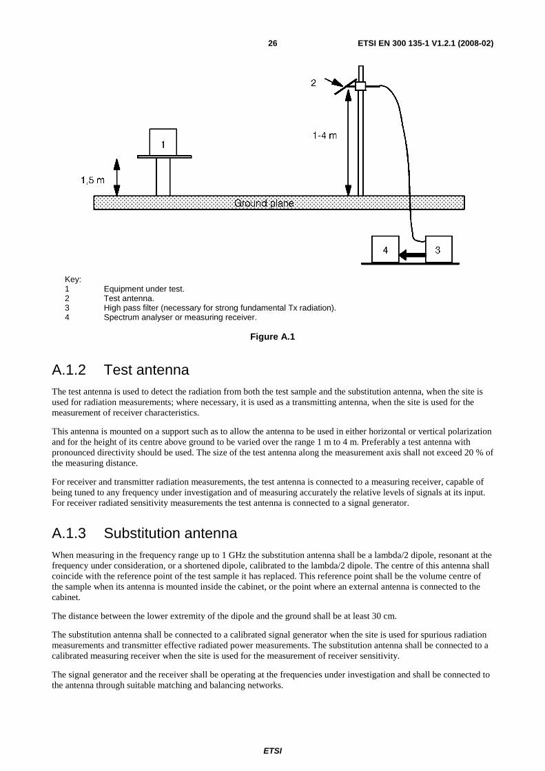
The setup is shown in figure A.1.
ETSI
ETSI EN 300 135-1 V1.2.1 (2008-02) 26
Key: 1 Equipment under test. 2 Test antenna. 3 High pass filter (necessary for strong fundamental Tx radiation). 4 Spectrum analyser or measuring receiver.
Figure A.1
A.1.2 Test antenna The test antenna is used to detect the radiation from both the test sample and the substitution antenna, when the site is used for radiation measurements; where necessary, it is used as a transmitting antenna, when the site is used for the measurement of receiver characteristics.
This antenna is mounted on a support such as to allow the antenna to be used in either horizontal or vertical polarization and for the height of its centre above ground to be varied over the range 1 m to 4 m. Preferably a test antenna with pronounced directivity should be used. The size of the test antenna along the measurement axis shall not exceed 20 % of the measuring distance.
For receiver and transmitter radiation measurements, the test antenna is connected to a measuring receiver, capable of being tuned to any frequency under investigation and of measuring accurately the relative levels of signals at its input. For receiver radiated sensitivity measurements the test antenna is connected to a signal generator.
A.1.3 Substitution antenna When measuring in the frequency range up to 1 GHz the substitution antenna shall be a lambda/2 dipole, resonant at the frequency under consideration, or a shortened dipole, calibrated to the lambda/2 dipole. The centre of this antenna shall coincide with the reference point of the test sample it has replaced. This reference point shall be the volume centre of the sample when its antenna is mounted inside the cabinet, or the point where an external antenna is connected to the cabinet.
The distance between the lower extremity of the dipole and the ground shall be at least 30 cm.
The substitution antenna shall be connected to a calibrated signal generator when the site is used for spurious radiation measurements and transmitter effective radiated power measurements. The substitution antenna shall be connected to a calibrated measuring receiver when the site is used for the measurement of receiver sensitivity.
The signal generator and the receiver shall be operating at the frequencies under investigation and shall be connected to the antenna through suitable matching and balancing networks.
ETSI
ETSI EN 300 135-1 V1.2.1 (2008-02) 27
A.1.4 Optional additional indoor site When the frequency of the signals being measured is greater than 80 MHz, use may be made of an indoor site. If this alternative site is used, this shall be recorded in the test report.
The measurement site may be a laboratory room with a minimum area of 6 m by 7 m and at least 2,7 m in height.
Apart from the measuring apparatus and the operator, the room shall be as free as possible from reflecting objects other than the walls, floor and ceiling.
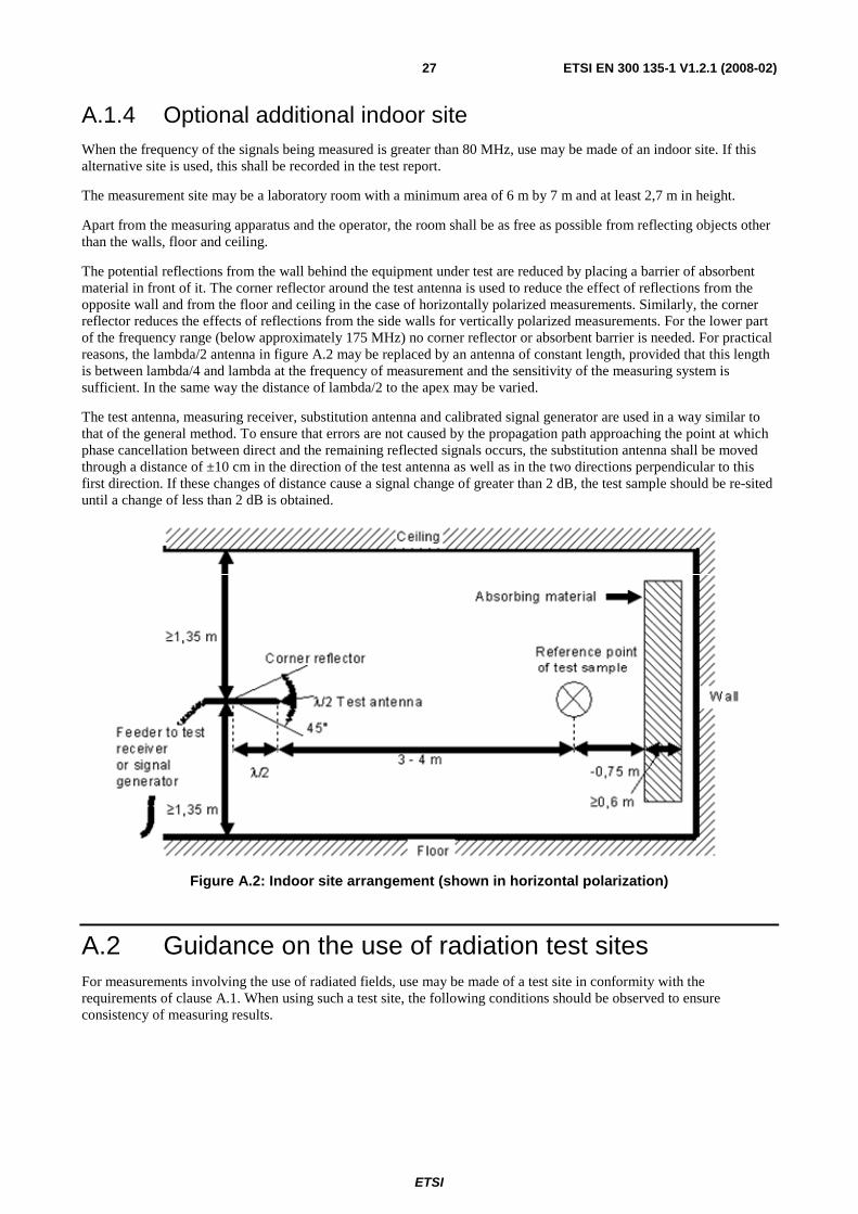
The potential reflections from the wall behind the equipment under test are reduced by placing a barrier of absorbent material in front of it. The corner reflector around the test antenna is used to reduce the effect of reflections from the opposite wall and from the floor and ceiling in the case of horizontally polarized measurements. Similarly, the corner reflector reduces the effects of reflections from the side walls for vertically polarized measurements. For the lower part of the frequency range (below approximately 175 MHz) no corner reflector or absorbent barrier is needed. For practical reasons, the lambda/2 antenna in figure A.2 may be replaced by an antenna of constant length, provided that this length is between lambda/4 and lambda at the frequency of measurement and the sensitivity of the measuring system is sufficient. In the same way the distance of lambda/2 to the apex may be varied.
The test antenna, measuring receiver, substitution antenna and calibrated signal generator are used in a way similar to that of the general method. To ensure that errors are not caused by the propagation path approaching the point at which phase cancellation between direct and the remaining reflected signals occurs, the substitution antenna shall be moved through a distance of ±10 cm in the direction of the test antenna as well as in the two directions perpendicular to this first direction. If these changes of distance cause a signal change of greater than 2 dB, the test sample should be re-sited until a change of less than 2 dB is obtained.
Figure A.2: Indoor site arrangement (shown in horizontal polarization)
A.2 Guidance on the use of radiation test sites For measurements involving the use of radiated fields, use may be made of a test site in conformity with the requirements of clause A.1. When using such a test site, the following conditions should be observed to ensure consistency of measuring results.
ETSI
ETSI EN 300 135-1 V1.2.1 (2008-02) 28
A.2.1 Measuring distance Evidence indicates that the measuring distance is not critical and does not significantly affect the measuring results, provided that the distance is not less than lambda/2 at the frequency of measurement, and the precautions described in this annex are observed. Measuring distances of 3 m, 5 m, 10 m and 30 m are in common use in European test laboratories.
A.2.2 Test antenna Different types of test antenna may be used, since performing substitution measurements reduces the effect of the errors on the measuring results.
Height variation of the test antenna over a range of 1 m to 4 m is essential in order to find the point at which the radiation is a maximum.
Height variation of the test antenna may not be necessary at the lower frequencies below about 100 MHz.
A.2.3 Substitution antenna Variations in the measuring results may occur with the use of different types of substitution antenna at the lower frequencies below about 80 MHz. Where a shortened dipole antenna is used at these frequencies, details of the type of antenna used should be included with the results of the tests carried out on the site. Correction factors shall be taken into account when shortened dipole antennas are used.
A.2.4 Artificial antenna The dimensions of the artificial antenna used during radiated measurements should be small in relation to the sample under test.
Where possible, a direct connection should be used between the artificial antenna and the test sample.
In cases where it is necessary to use a connecting cable, precautions should be taken to reduce the radiation from this cable by, for example, the use of ferrite cores or double screened cables.
A.2.5 Auxiliary cables The position of auxiliary cables (power supply and microphone cables etc) which are not adequately decoupled may cause variations in the measuring results. In order to get reproducible results, cables and wires of auxiliaries should be arranged vertically downwards (through a hole in the non conducting support).
A.3 Further optional alternative indoor test site using an anechoic chamber
For radiation measurements when the frequency of the signals being measured is greater than 25 MHz, use may be made of an indoor site being a well-shielded anechoic chamber simulating free space environment. If such a chamber is used, this shall be recorded in the test report.
The test antenna, measuring receiver, substitution antenna and calibrated signal generator are used in a way similar to that of the general method, clause A.1. In the range between 25 MHz and 100 MHz some additional calibration may be necessary.
An example of a typical measurement site may be an electrically shielded anechoic chamber being 10 m long, 5 m broad and 5 m high. Walls and ceiling should be coated with RF absorbers of 1m height. The base should be covered with absorbing material 1m thick, and a wooden floor, able to carry test equipment and operators. A measuring distance of 3 m to 5 m in the long middle axis of the chamber can be used for measurements. The construction of the anechoic chamber is described in the following clauses.
ETSI
ETSI EN 300 135-1 V1.2.1 (2008-02) 29
A.3.1 Example of the construction of a shielded anechoic chamber
Free-field measurements can be simulated in a shielded measuring chamber where the walls are coated with RF absorbers. Figure A.3 shows the requirements for shielding loss and wall return loss of such a room. As dimensions and characteristics of usual absorber materials are critical below 100 MHz (height of absorbers < 1 m, reflection attenuation < 20 dB) such a room is preferably suitable for measurements above 100 MHz. Figure A.4 shows the construction of a shielded measuring chamber having a base area of 5 m by 10 m and a height of 5 m. Ceilings and walls are coated with pyramidal formed absorbers approximately 1m high. The base is covered with absorbers which are able to carry and which forms a sort of floor. The available internal dimensions of the room are 3 m x 8 m x 3 m, so that a measuring distance of maximum 5 m length in the middle axis of this room is available.
At 100 MHz the measuring distance can be extended up to a maximum of 2 lambdas. The floor absorbers reject floor reflections so that the antenna height need not be changed and floor reflection influences need not be considered. All measuring results can therefore be checked with simple calculations and the measuring tolerances have the smallest possible values due to the simple measuring configuration.
For special measurements it can be necessary to re-introduce floor reflections. Taking away the floor absorbers would mean a removal of approximately 24 m3 absorber material. Therefore the floor absorbers are covered with metal plates of metallic nets instead.
A.3.2 Influence of parasitic reflections in anechoic chambers For free-space propagation in the far field condition the correlation E=Eo (Ro/R) is valid for the dependence of the field strength E on the distance R, whereby Eo is the reference field strength in the reference distance Ro. It is useful to use just this correlation for comparison measurements, as all constants are eliminated with the ratio and neither cable attenuation nor antenna mismatch or antenna dimensions are of importance. Deviations from the ideal curve can be seen easily if the logarithm of the above equation is used, because the ideal correlation of field strength and distance can then be shown as a straight line and the deviations occurring in practice are clearly visible. This indirect method shows the disturbances due to reflections more readily and is far less problematical than the direct measurement of reflection attenuation.
With an anechoic chamber of the dimensions suggested in clause A.3 at low frequencies up to 100 MHz there are no far field conditions, and therefore reflections are stronger so that careful calibration is necessary. In the medium frequency range from 100 MHz to 1 GHz the dependence of the field strength on the distance meets the expectations very well. In the frequency range of 1 GHz to 2 GHz, because more reflections will occur, the dependence of the field strength on the distance will not correlate so closely.
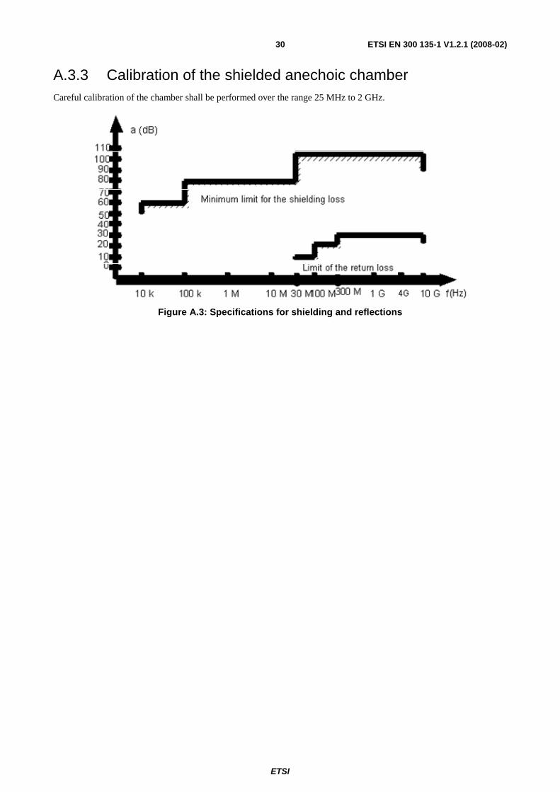
ETSI
ETSI EN 300 135-1 V1.2.1 (2008-02) 30
A.3.3 Calibration of the shielded anechoic chamber Careful calibration of the chamber shall be performed over the range 25 MHz to 2 GHz.
Figure A.3: Specifications for shielding and reflections
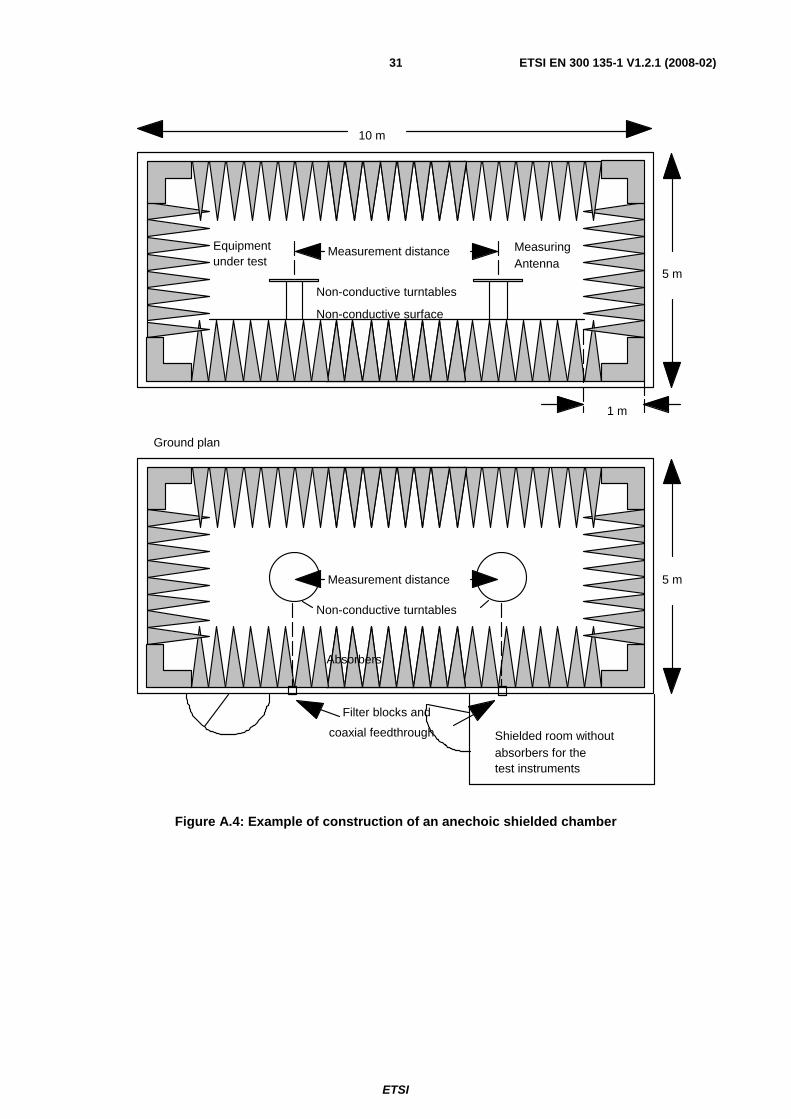
ETSI
ETSI EN 300 135-1 V1.2.1 (2008-02) 31
10 m
5 m
1 m
Equipmentunder test
Non-conductive turntables
Non-conductive surface
Measurement distance
Measurement distance
Non-conductive turntables
MeasuringAntenna
Filter blocks and
coaxial feedthrough Shielded room withoutabsorbers for thetest instruments
5 m
Ground plan
Absorbers
Figure A.4: Example of construction of an anechoic shielded chamber
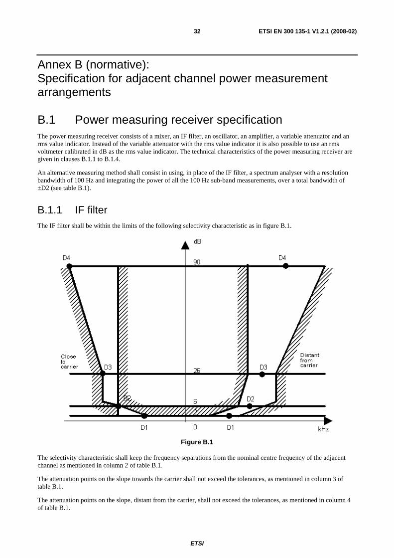
ETSI
ETSI EN 300 135-1 V1.2.1 (2008-02) 32
Annex B (normative): Specification for adjacent channel power measurement arrangements
B.1 Power measuring receiver specification The power measuring receiver consists of a mixer, an IF filter, an oscillator, an amplifier, a variable attenuator and an rms value indicator. Instead of the variable attenuator with the rms value indicator it is also possible to use an rms voltmeter calibrated in dB as the rms value indicator. The technical characteristics of the power measuring receiver are given in clauses B.1.1 to B.1.4.
An alternative measuring method shall consist in using, in place of the IF filter, a spectrum analyser with a resolution bandwidth of 100 Hz and integrating the power of all the 100 Hz sub-band measurements, over a total bandwidth of ±D2 (see table B.1).
B.1.1 IF filter The IF filter shall be within the limits of the following selectivity characteristic as in figure B.1.
Figure B.1
The selectivity characteristic shall keep the frequency separations from the nominal centre frequency of the adjacent channel as mentioned in column 2 of table B.1.
The attenuation points on the slope towards the carrier shall not exceed the tolerances, as mentioned in column 3 of table B.1.
The attenuation points on the slope, distant from the carrier, shall not exceed the tolerances, as mentioned in column 4 of table B.1.
ETSI
ETSI EN 300 135-1 V1.2.1 (2008-02) 33
Table B.1: Selectivity characteristics of the "receiver"
1 Attenuation Points
2 Frequency Separations
3 Tolerance towards C
4 Tolerance distant from C
D1 (2 dB) 3 kHz +1,35 kHz ±2 kHz D2 (6 dB) 4,25 kHz ±0,1 kHz ±2 kHz D3 (26 dB) 5,5 kHz -1,35 kHz ±2 kHz D4 (90 dB) 9,5 kHz -5,35 kHz +2 kHz and -6 kHz
The minimum attenuation of the filter outside the 90 dB attenuation points must be equal to or greater than 90 dB.
B.1.2 Variable attenuator The attenuation indicator shall have a minimum range of 80 dB and a reading accuracy of 1 dB.
B.1.3 Rms value indicator The instrument shall accurately indicate non-sinusoidal signals in a ratio of up to 10:1 between peak value and rms value.
B.1.4 Oscillator and amplifier The oscillator and the amplifier shall be designed in such a way that the measurement of the adjacent channel power of a low-noise unmodulated transmitter, whose self-noise has a negligible influence on the measurement result, yields a measured value of < -80 dB referred to the carrier of the oscillator.
ETSI
ETSI EN 300 135-1 V1.2.1 (2008-02) 34
Annex C (informative): Bibliography ETSI TR 102 273 (all parts) (V1.2.1): "Electromagnetic compatibility and Radio spectrum Matters (ERM); Improvement on Radiated Methods of Measurement (using test site) and evaluation of the corresponding measurement uncertainties".
ETSI EN 301 489-1 (V1.7.1): "Electromagnetic compatibility and Radio spectrum Matters (ERM); ElectroMagnetic Compatibility (EMC) standard for radio equipment and services; Part 1: Common technical requirements".
ETSI EN 301 489-13 (V1.2.1): "Electromagnetic compatibility and Radio spectrum Matters (ERM); ElectroMagnetic Compatibility (EMC) standard for radio equipment and services; Part 13: Specific conditions for Citizens' Band (CB) radio and ancillary equipment (speech and non-speech)".
Directive 2004/108/EC of the European Parliament and of the Council of 15 December on the approximation of the laws of the Member States relating to electromagnetic compatibility and replacing Directive 89/336/EC.
Directive 1999/5/EC of the European Parliament and of the Council of 9 March 1999 on radio equipment and telecommunications terminal equipment and the mutual recognition of their conformity (R&TTE Directive).
ETSI
ETSI EN 300 135-1 V1.2.1 (2008-02) 35
History
Document history
Edition 1 June 1991 Publication as ETS 300 135
Amendment 1 March 1997 Amendment 1 to 1st Edition of ETS 300 135
V1.1.2 August 2000 Publication
V1.2.1 July 2007 Public Enquiry PE 20071116: 2007-07-18 to 2007-11-16
V1.2.1 December 2007 Vote V 20080222: 2007-12-24 to 2008-02-22
V1.2.1 February 2008 Publication
Related Documents