EUROCODES Background and Applications “Dissemination of information for training” workshop 18-20 February 2008 Brussels EN 1992 Eurocode 2: Design of concrete structures Organised by European Commission: DG Enterprise and Industry, Joint Research Centre with the support of CEN/TC250, CEN Management Centre and Member States

Welcome message from author
This document is posted to help you gain knowledge. Please leave a comment to let me know what you think about it! Share it to your friends and learn new things together.
Transcript
EUROCODESBackground and Applications
“Dissemination of information for training” workshop 18-20 February 2008 Brussels
EN 1992 Eurocode 2: Design of concrete structures Organised by European Commission: DG Enterprise and Industry, Joint Research Centre with the support of CEN/TC250, CEN Management Centre and Member States


Wednesday, February 20 – Palais des Académies EN 1992 - Eurocode 2: Design of concrete structures Baron Lacquet room
9:00-10:30 EN1992-1-1 J. Walraven TU Delft
10:30-11:00 Coffee
11:00-12:00 EN1992-1-1 J. Walraven TU Delft
12:00-13:30 Lunch
13:30-15:30 EN1992-2 G. Mancini Politecnico di Torino
15:30-16:00 Coffee
16:00-17:00 EN1992-3 T. Jones Arup
All workshop material will be available at http://eurocodes.jrc.ec.europa.eu

EN1992-1-1
J. Walraven TU Delft

1
02 February 2008
1
Eurocode 2: Design of concrete structuresEN1992-1-1
Symposium Eurocodes: Backgrounds and Applications, Brussels 18-20 February 2008
J.C. Walraven
02 February 2008 2
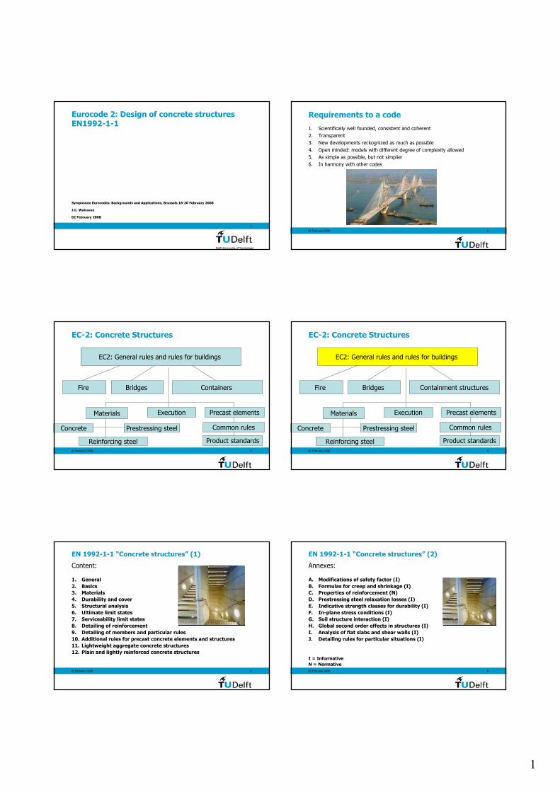
Requirements to a code
1. Scientifically well founded, consistent and coherent2. Transparent3. New developments reckognized as much as possible4. Open minded: models with different degree of complexity allowed5. As simple as possible, but not simplier6. In harmony with other codes
02 February 2008 3
EC-2: Concrete Structures
Fire
EC2: General rules and rules for buildings
Bridges Containers
Materials
Concrete
Reinforcing steel
Prestressing steel
Execution Precast elements
Common rules
Product standards02 February 2008 4
EC-2: Concrete Structures
Fire
EC2: General rules and rules for buildings
Bridges Containment structures
Materials
Concrete
Reinforcing steel
Prestressing steel
Execution Precast elements
Common rules
Product standards
02 February 2008 5
EN 1992-1-1 “Concrete structures” (1)
Content:
1. General2. Basics3. Materials4. Durability and cover5. Structural analysis6. Ultimate limit states7. Serviceability limit states8. Detailing of reinforcement9. Detailing of members and particular rules10. Additional rules for precast concrete elements and structures11. Lightweight aggregate concrete structures12. Plain and lightly reinforced concrete structures
02 February 2008 6
EN 1992-1-1 “Concrete structures” (2)
Annexes:
A. Modifications of safety factor (I)B. Formulas for creep and shrinkage (I)C. Properties of reinforcement (N) D. Prestressing steel relaxation losses (I)E. Indicative strength classes for durability (I)F. In-plane stress conditions (I)G. Soil structure interaction (I)H. Global second order effects in structures (I)I. Analysis of flat slabs and shear walls (I)J. Detailing rules for particular situations (I)
I = InformativeN = Normative
2
02 February 2008 7
EN 1992-1-1 “Concrete structures” (3)
In EC-2 “Design of concrete structures –Part 1: General rules and rules for buildings
109 national choices are possible
02 February 2008
8
Chapter: 3 Materials
J.C. Walraven
02 February 2008 9
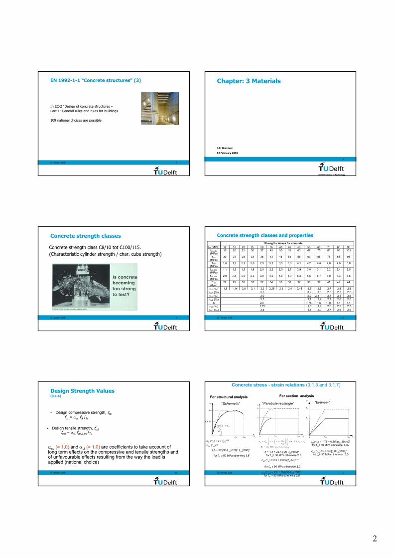
Concrete strength classes
Concrete strength class C8/10 tot C100/115.(Characteristic cylinder strength / char. cube strength)
02 February 2008 10
Strength classes for concretefck (MPa) 12 16 20 25 30 35 40 45 50 55 60 70 80 90
fck,cube(MPa)
15 20 25 30 37 45 50 55 60 67 75 85 95 105
fcm(MPa)
20 24 28 33 38 43 48 53 58 63 68 78 88 98
fctm(MPa)
1,6 1,9 2,2 2,6 2,9 3,2 3,5 3,8 4,1 4,2 4,4 4,6 4,8 5,0
fctk,0,05(MPa)
1 1 1,3 1,5 1,8 2,0 2,2 2,5 2,7 2,9 3,0 3,1 3,2 3,4 3,5
fctk,0,95(MPa)
2,0 2,5 2,9 3,3 3,8 4,2 4,6 4,9 5,3 5,5 5,7 6,0 6,3 6,6
Ecm(Gpa)
27 29 30 31 32 34 35 36 37 38 39 41 42 44
εc1 (‰) 1,8 1,9 2,0 2,1 2,2 2,25 2,3 2,4 2,45 2,5 2,6 2,7 2,8 2,8εcu1 (‰) 3,5 3,2 3,0 2,8 2,8 2,8εc2 (‰) 2,0 2,2 2,3 2,4 2,5 2,6εcu2 (‰) 3,5 3,1 2,9 2,7 2,6 2,6
n 2,0 1,75 1,6 1,45 1,4 1,4εc3 (‰) 1,75 1,8 1,9 2,0 2,2 2,3εcu3 (‰) 3,5 3,1 2,9 2,7 2,6 2,6
Concrete strength classes and properties
02 February 2008 11
Design Strength Values(3.1.6)
• Design compressive strength, fcdfcd = αcc fck /γc
• Design tensile strength, fctdfctd = αct fctk,0.05 /γc
αcc (= 1,0) and αct (= 1,0) are coefficients to take account of long term effects on the compressive and tensile strengths and of unfavourable effects resulting from the way the load is applied (national choice)
02 February 2008 12
Concrete stress - strain relations (3.1.5 and 3.1.7)
fcd
ε c2
σ c
ε cu2 ε c0
fck
For section analysis
“Parabola-rectangle”
c3 εcu30
fcd
ε
σ c
ε c
fck
“Bi-linear”
fcm
0,4 fcm
ε c1
σ c
ε cu1ε c
tan α = E cm
α
For structural analysis
“Schematic”
εc1 (0/00) = 0,7 fcm0,31
εcu1 (0/00) =
2,8 + 27[(98-fcm)/100]4 fcm)/100]4
for fck ≥ 50 MPa otherwise 3.5εc2 (
0/00) = 2,0 + 0,085(fck-50)0,53
for fck ≥ 50 MPa otherwise 2,0
εcu2 (0/00) = 2,6 + 35 [(90-fck)/100]4for fck ≥ 50 MPa otherwise 3,5
n = 1,4 + 23,4 [(90- fck)/100]4for fck≥ 50 MPa otherwise 2,0
σ fn
cc cd c c2
c2
1 1 for 0ε ε εε
= − − ≤ <
σ f forc cd c2 c cu2ε ε ε= ≤ ≤
εc3 (0/00) = 1,75 + 0,55 [(fck-50)/40]
for fck≥ 50 MPa otherwise 1,75
εcu3 (0/00) =2,6+35[(90-fck)/100]4
for fck≥ 50 MPa otherwise 3,5
3
02 February 2008 13
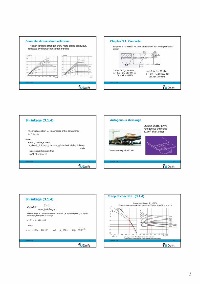
Concrete stress-strain relations
- Higher concrete strength show more brittle behaviour, reflected by shorter horizontal branche
02 February 2008 14
Chapter 3.1: Concrete
Simplified σ - ε relation for cross sections with non rectangular cross-section
λ= 0,8 for fck ≤ 50 MPaλ = 0,8 – (fck-50)/400 for
50 ≤ fck ≤ 90 MPa
η = 1,0 for fck ≤ 50 MPaη = 1,0 – (fck-50)/200 for
50 ≤ fck ≤ 90 MPa
02 February 2008 15
Shrinkage (3.1.4)
• The shrinkage strain εcs is composed of two components:εcs = εcd + εca
where- drying shrinkage strain
εcd(t) = βds(t, ts)⋅kh⋅εcd,0 where εcd,0 is the basic drying shrinkagestrain
- autogenous shrinkage strainεca(t) = βas(t)⋅εca(∞)
02 February 2008 16
Autogenous shrinkage
l
Stichtse Bridge, 1997:Autogenous shrinkage 20.10-3 after 2 days
Concrete strength fc=90 MPa
02 February 2008 17
Shrinkage (3.1.4)
3004,0)(
)(),(htt
tttts
ssds
+−
−=β
)()()( ∞= caasca tt εβε
610)10(5,2)( −⋅−=∞ ckca fε
where t = age of concrete at time considered, ts= age at beginning of drying shrinkage (mostly end of curing)
where
)2,0exp(1)( 5,0ttas −−=βand
02 February 2008 18
Creep of concrete (3.1.4)
01,02,03,04,05,06,07,0100
50
30
1
2
3
5
10
20
t 0
ϕ (∞, t 0)
SN R
100 300 500 700 900 1100 1300 1500
C20/25C25/30C30/37C35/45C40/50C45/55C50/60 C55/67C60/75 C70/85
C90/105C80/95
h 0 (mm)
Inside conditions – RH = 50%Example: 600 mm thick slab, loading at 30 days, C30/37 - ϕ = 1,8
h0 = 2Ac/u where Ac is the cross-section area and u is perimeter of the member in contact with the atmosphere
4
02 February 2008 19
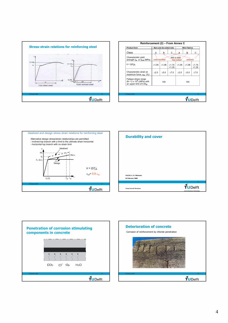
Stress-strain relations for reinforcing steel
02 February 2008 20
Product form Bars and de-coiled rods Wire Fabrics Class
A
B
C
A
B
C
Characteristic yield strength fyk or f0,2k (MPa)
400 to 600
k = (ft/fy)k
≥1,05
≥1,08
≥1,15 <1,35
≥1,05
≥1,08
≥1,15 <1,35
Characteristic strain at maximum force, εuk (%)
≥2,5
≥5,0
≥7,5
≥2,5
≥5,0
≥7,5
Fatigue stress range
(N = 2 x 10⁶) (MPa) with an upper limit of 0.6fyk
150
100
cold worked seismichot rolled
Reinforcement (2) – From Annex C
02 February 2008 21
εudε
σ
fyd/ Es
fyk
kfyk
fyd = fyk/γs
kfyk/γs
Idealised
Design
εuk
εud= 0.9 εuk
k = (ft/fy)k
Alternative design stress/strain relationships are permitted:- inclined top branch with a limit to the ultimate strain horizontal - horizontal top branch with no strain limit
Idealized and design stress strain relations for reinforcing steel
02 February 2008
22
Durability and cover
Prof.dr.ir. J.C. Walraven
Group Concrete Structures
02 February 2008 23
Penetration of corrosion stimulating components in concrete
02 February 2008 24
Deterioration of concreteCorrosion of reinforcement by chloride penetration
5
02 February 2008 25
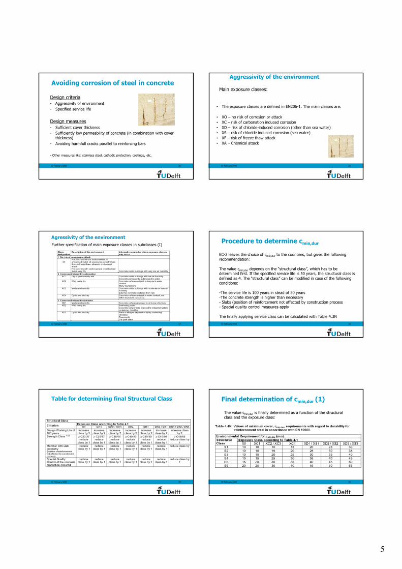
Design criteria- Aggressivity of environment- Specified service life
Design measures- Sufficient cover thickness- Sufficiently low permeability of concrete (in combination with cover
thickness)- Avoiding harmfull cracks parallel to reinforcing bars
- Other measures like: stainless steel, cathodic protection, coatings, etc.
Avoiding corrosion of steel in concrete
02 February 2008 26
Aggressivity of the environment
• The exposure classes are defined in EN206-1. The main classes are:
• XO – no risk of corrosion or attack• XC – risk of carbonation induced corrosion• XD – risk of chloride-induced corrosion (other than sea water)• XS – risk of chloride induced corrosion (sea water)• XF – risk of freeze thaw attack• XA – Chemical attack
Main exposure classes:
02 February 2008 27
Agressivity of the environmentFurther specification of main exposure classes in subclasses (I)
02 February 2008 28
Procedure to determine cmin,dur
EC-2 leaves the choice of cmin,dur to the countries, but gives the following recommendation:
The value cmin,dur depends on the “structural class”, which has to be determined first. If the specified service life is 50 years, the structural class is defined as 4. The “structural class” can be modified in case of the following conditions:
-The service life is 100 years in stead of 50 years -The concrete strength is higher than necessary - Slabs (position of reinforcement not affected by construction process- Special quality control measures apply
The finally applying service class can be calculated with Table 4.3N
02 February 2008 29
Table for determining final Structural Class
02 February 2008 30
Final determination of cmin,dur (1)
The value cmin,dur is finally determined as a function of the structural class and the exposure class:

6
02 February 2008 31
Special considerations
In case of stainless steel the minimum cover may be reduced. Thevalue of the reduction is left to the decision of the countries (0 if no further specification).
02 February 2008 32
Structural Analysis
02 February 2008 33
Methods to analyse structures
Linear elastic analysis
1. Suitable for ULS and SLS2. Assumptions:
- uncracked cross-sections- linear σ - ε relations- mean E-modulus
3. Effect of imposed deformationsin ULS to be calculated withreduced stiffnesses and creep
02 February 2008 34
Na
Nb
Hi
l
iθ
iθNa
Nb
Hi
/2iθ
/2iθ
Forces due to geometric imperfections on structures(5.2)
Bracing System Floor Diaphragm Roof
Hi = θi (Nb-Na) Hi = θi (Nb+Na)/2 Hi = θi Na
02 February 2008 35
Methods to analyse structures5.5 Linear elastic analysis with limited redistribution
1. Valid for 0,5 ≤ l1/ l2 ≤ 2,02. Ratio of redistribution δ, with
δ ≥ k1 + k2 xu/d for fck ≤ 50 MPaδ ≥ k3 + k4 xu/d for fck > 50 MPa
δ ≥ k5 for reinforcement class B or Cδ ≥ k6 for reinforcement class A
M2
M1
l1 l2
02 February 2008 36
0
5
10
15
20
25
30
35
0.25 0.30 0.35 0.40 0.45 0.50 0.55 0.60x /d
% re
dist
fck =70 fck =60 fck =50
Redistribution limits for Class B & C steel
7
02 February 2008 37
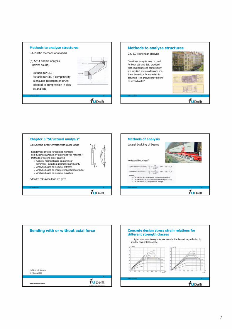
Methods to analyse structures
5.6 Plastic methods of analysis
(b) Strut and tie analysis(lower bound)
- Suitable for ULS- Suitable for SLS if compatibility
is ensured (direction of strutsoriented to compression in elas-tic analysis
02 February 2008 38
Methods to analyse structuresCh. 5.7 Nonlinear analysis
“Nonlinear analysis may be usedfor both ULS and SLS, providedthat equilibrium and compatibilityare satisfied and an adequate non-linear behaviour for materials isassumed. The analysis may be firstor second order”.
02 February 2008 39
Chapter 5 “Structural analysis”
5.8 Second order effects with axial loads
- Slenderness criteria for isolated membersand buildings (when is 2nd order analysis required?)
- Methods of second order analysis• General method based on nonlinear
behaviour, including geometric nonlinearity• Analysis based on nominal stiffness• Analysis based on moment magnification factor• Analysis based on nominal curvature
Extended calculation tools are given
02 February 2008 40
Methods of analysis
Lateral buckling of beams
No lateral buckling if:
02 February 2008
41
Bending with or without axial force
Prof.dr.ir. J.C. Walraven
Group Concrete Structures
02 February 2008 42
Concrete design stress strain relations fordifferent strength classes
- Higher concrete strength shows more brittle behaviour, reflected byshorter horizontal branche
8
02 February 2008 43
Concrete design stress - strain relations (3.1.5 and 3.1.7)for section analysis
c3 εcu30
fcd
ε
σ c
ε c
fck
“Bi-linear”
εc2 (0/00) = 2,0 + 0,085(fck-50)0,53
for fck ≥ 50 MPa otherwise 2,0
εcu2 (0/00) = 2,6 + 35 [(90-fck)/100]4for fck ≥ 50 MPa otherwise 3,5
n = 1,4 + 23,4 [(90- fck)/100]4for fck≥ 50 MPa otherwise 2,0
σ fn
cc cd c c2
c2
1 1 for 0ε ε εε
= − − ≤ <
σ f forc cd c2 c cu2ε ε ε= ≤ ≤ εc3 (0/00) = 1,75 + 0,55 [(fck-50)/40]
for fck≥ 50 MPa otherwise 1,75
εcu3 (0/00) =2,6+35[(90-fck)/100]4
for fck≥ 50 MPa otherwise 3,5
fcd
ε c2
σ c
ε cu 2 ε c0
fck
“Parabola-rectangle”
02 February 2008 44
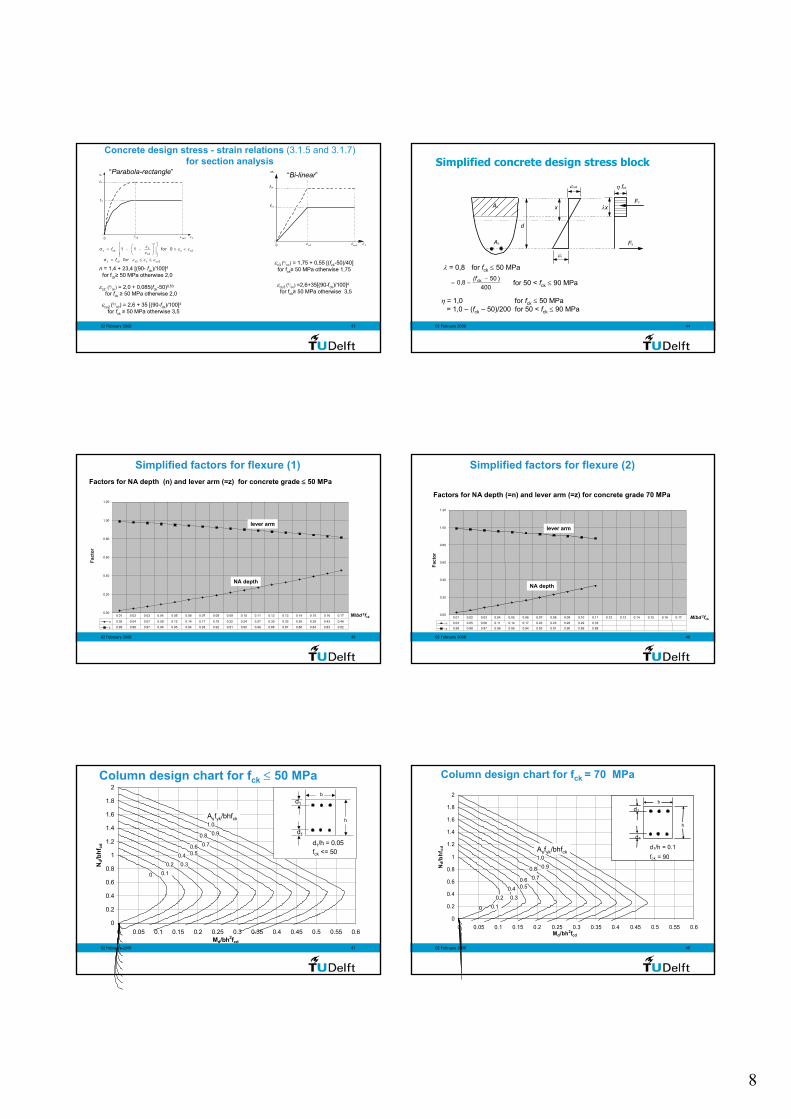
Simplified concrete design stress block
As
d
η fcd
Fs
λx
εs
x
εcu3
Fc Ac
400)508,0 ck −
−=(f
for 50 < fck ≤ 90 MPa
λ = 0,8 for fck ≤ 50 MPa
η = 1,0 for fck ≤ 50 MPa= 1,0 – (fck – 50)/200 for 50 < fck ≤ 90 MPa
02 February 2008 45
Factors for NA depth (n) and lever arm (=z) for concrete grade ≤ 50 MPa
0.00
0.20
0.40
0.60
0.80
1.00
1.20
M/bd 2fck
Fact
or
n 0.02 0.04 0.07 0.09 0.12 0.14 0.17 0.19 0.22 0.24 0.27 0.30 0.33 0.36 0.39 0.43 0.46
z 0.99 0.98 0.97 0.96 0.95 0.94 0.93 0.92 0.91 0.90 0.89 0.88 0.87 0.86 0.84 0.83 0.82
0.01 0.02 0.03 0.04 0.05 0.06 0.07 0.08 0.09 0.10 0.11 0.12 0.13 0.14 0.15 0.16 0.17
lever arm
NA depth
Simplified factors for flexure (1)
02 February 2008 46
Factors for NA depth (=n) and lever arm (=z) for concrete grade 70 MPa
0.00
0.20
0.40
0.60
0.80
1.00
1.20
M/bd 2fck
Fact
or
n 0.03 0.05 0.08 0.11 0.14 0.17 0.20 0.23 0.26 0.29 0.33
z 0.99 0.98 0.97 0.96 0.95 0.94 0.93 0.91 0.90 0.89 0.88
0.01 0.02 0.03 0.04 0.05 0.06 0.07 0.08 0.09 0.10 0.11 0.12 0.13 0.14 0.15 0.16 0.17
Simplified factors for flexure (2)
lever arm
NA depth
02 February 2008 47
Column design chart for fck ≤ 50 MPa
0
0.2
0.4
0.6
0.8
1
1.2
1.4
1.6
1.8
2
0 0.05 0.1 0.15 0.2 0.25 0.3 0.35 0.4 0.45 0.5 0.55 0.6Md/bh2fcd
Nd/b
hfcd
h
b
d1/h = 0.05fck <= 50
d1
d1
Asfyk/bhfck
0
0.20.1
0.30.4 0.5
0.6 0.70.8 0.9
1.0
02 February 2008 48
Column design chart for fck = 70 MPa
0
0.2
0.4
0.6
0.8
1
1.2
1.4
1.6
1.8
2
0 0.05 0.1 0.15 0.2 0.25 0.3 0.35 0.4 0.45 0.5 0.55 0.6Md/bh2fcd
Nd/
bhf c
d
h
b
d1/h = 0.1fck = 90
d1
d1
Asfyk/bhfck
0
0.20.1
0.30.4 0.5
0.6 0.70.8 0.9
1.0

9
02 February 2008
49
Shear
Prof.dr.ir. J.C. Walraven
Group Concrete Structures
02 February 2008 50
Principles of shear control in EC-2
Until a certain shear force VRd,c no calculated shear reinforcement is necessary (only in beams minimum shear reinforcement is prescribed)
If the design shear force is larger than this value VRd,c shear reinforcement is necessary for the full design shear force. This shear reinforcement is calculated with the variable inclination truss analogy. To this aim the strut inclination may be chosen between two values (recommended range 1≤ cot θ ≤ 2,5)
The shear reinforcement may not exceed a defined maximum value to ensure yielding of the shear reinforcement
02 February 2008 51
Concrete slabs without shear reinforcement
Shear resistance VRd,c governed by shear flexure failure: shear crack develops from flexural crack
02 February 2008 52
Concrete slabs without shear reinforcement
Shear resistance VRd,c governed by shear tension failure: crack occurs in web in region uncracked in flexure
Prestressed hollow core slab
02 February 2008 53
Concrete beam reinforced in shear
Shear failure introduced by yielding of stirrups, followed by strut rotation until web crushing
02 February 2008 54
Principle of variabletruss actionapproach “Variable inclination struts”: a realistic
Stage 1: web uncracked in shear
Stage 2: inclined cracks occurStage 3: stabilized inclined cracksStage 4: yielding of stirrups,
further rotation, finallyweb crushing
Strut rotation as measured in tests(TU Delft)
10
02 February 2008 55
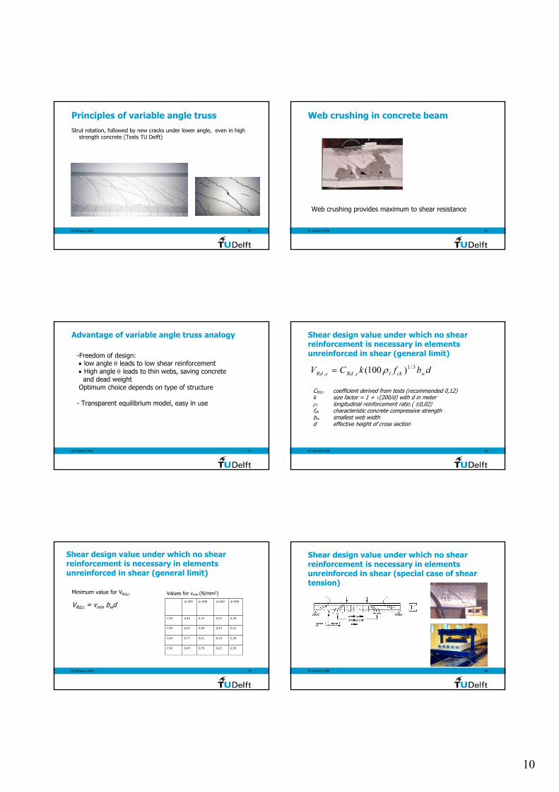
Principles of variable angle trussStrut rotation, followed by new cracks under lower angle, even in high
strength concrete (Tests TU Delft)
02 February 2008 56
Web crushing in concrete beam
Web crushing provides maximum to shear resistance
02 February 2008 57
Advantage of variable angle truss analogy
-Freedom of design:• low angle θ leads to low shear reinforcement• High angle θ leads to thin webs, saving concrete
and dead weightOptimum choice depends on type of structure
- Transparent equilibrium model, easy in use
02 February 2008 58
Shear design value under which no shear reinforcement is necessary in elements unreinforced in shear (general limit)
dbfkCV wcklcRdcRd3/1
,, )100( ρ=
CRd,c coefficient derived from tests (recommended 0,12)k size factor = 1 + √(200/d) with d in meterρl longitudinal reinforcement ratio ( ≤0,02)fck characteristic concrete compressive strengthbw smallest web widthd effective height of cross section
02 February 2008 59
Shear design value under which no shear reinforcement is necessary in elements unreinforced in shear (general limit)
Minimum value for VRd,c:
VRd,c = vmin bwd
0,580,620,700,89C80
0,500,540,610,77C60
0,410,440,490,63C40
0,290,250,350,44C20
d=800d=600d=400d=200
Values for vmin (N/mm2)
02 February 2008 60
Shear design value under which no shear reinforcement is necessary in elements unreinforced in shear (special case of shear tension)
11
02 February 2008 61
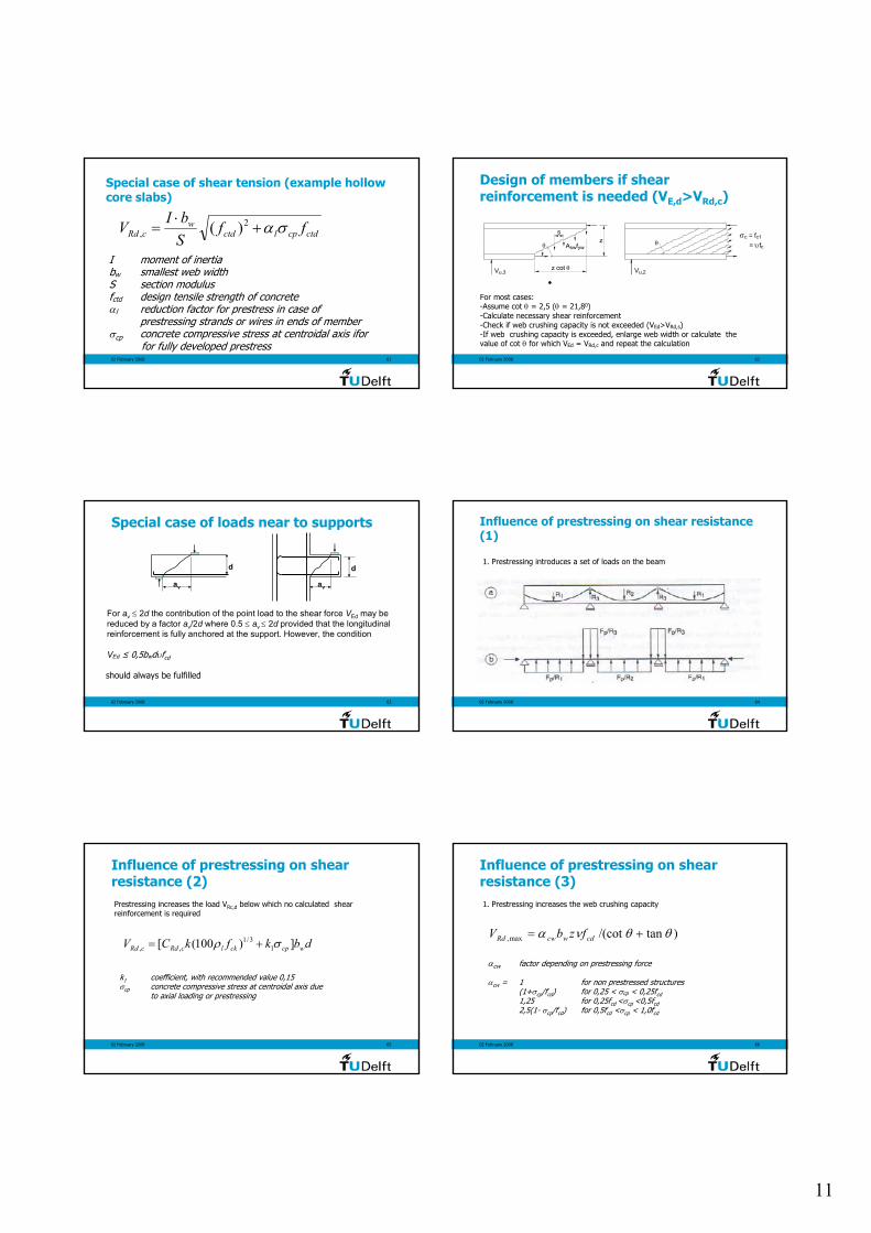
Special case of shear tension (example hollow core slabs)
ctdcplctdw
cRd ffSbIV σα+
⋅= 2
, )(
I moment of inertiabw smallest web widthS section modulusfctd design tensile strength of concreteαl reduction factor for prestress in case of
prestressing strands or wires in ends of memberσcp concrete compressive stress at centroidal axis ifor
for fully developed prestress02 February 2008 62
Design of members if shear reinforcement is needed (VE,d>VRd,c)
θ
Vu,2
θ
Vu,3
s z
z cot θ
Afswyw
θ
Vu,2
σc c1= f= fυ cθ
Vu,3
sz
z cot θ
A fsw yw
For most cases:-Assume cot θ = 2,5 (θ = 21,80)-Calculate necessary shear reinforcement -Check if web crushing capacity is not exceeded (VEd>VRd,s)-If web crushing capacity is exceeded, enlarge web width or calculate the value of cot θ for which VEd = VRd,c and repeat the calculation
02 February 2008 63
For av ≤ 2d the contribution of the point load to the shear force VEd may be reduced by a factor av/2d where 0.5 ≤ av ≤ 2d provided that the longitudinal reinforcement is fully anchored at the support. However, the condition
VEd ≤ 0,5bwdυfcd
should always be fulfilled
dd
av av
Special case of loads near to supports
02 February 2008 64
Influence of prestressing on shear resistance (1)
1. Prestressing introduces a set of loads on the beam
02 February 2008 65
Influence of prestressing on shear resistance (2)Prestressing increases the load VRc,d below which no calculated shear reinforcement is required
dbkfkCV wcpcklcRdcRd ])100([ 13/1
,, σρ +=
k1 coefficient, with recommended value 0,15σcp concrete compressive stress at centroidal axis due
to axial loading or prestressing
02 February 2008 66
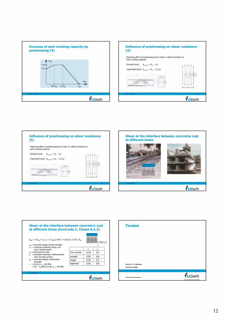
Influence of prestressing on shear resistance (3)1. Prestressing increases the web crushing capacity
αcw factor depending on prestressing force
αcw = 1 for non prestressed structures(1+σcp/fcd) for 0,25 < σcp < 0,25fcd1,25 for 0,25fcd <σcp <0,5fcd2,5(1- σcp/fcd) for 0,5fcd <σcp < 1,0fcd
)tan/(cotmax, θθνα += cdwcwRd fzbV
12
02 February 2008 67
Increase of web crushing capacity by prestressing (4)
02 February 2008 68
Influence of prestressing on shear resistance (4)
Reducing effect of prestressing duct (with or without tendon) on web crushing capacity
Grouted ducts bw,nom = bw - Σφ
Ungrouted ducts bw,nom = bw – 1,2 Σφ
02 February 2008 69
Influence of prestressing on shear resistance (5)
Reducing effect of prestressing duct (with or without tendon) on web crushing capacity
Grouted ducts bw,nom = bw - Σφ
Ungrouted ducts bw,nom = bw – 1,2 Σφ
02 February 2008 70
Shear at the interface between concretes cast at different times
02 February 2008 71
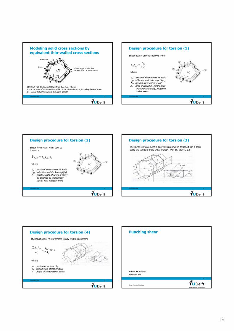
Shear at the interface between concrete’s cast at different times (Eurocode 2, Clause 6.5.2)
vRdi = c⋅fctd + µ⋅σn + ρ⋅fyd (µ⋅sin β + cos β) ≤ 0,5 ν⋅fcd
fctd =concrete design tensile strengthσn = eventual confining stress, not
from reinforcementρ= reinforcement ratioβ = inclination between reinforcement
and concrete surfacefcd = concrete design compressive
strengthυ = 0,6 for fck ≤ 60 MPa
= 0,9 – fck/200≥0,5 for fck ≥ 60 MPa0,8
0,70,6
0,5
µ
0,45rough
0,50
0,35
0,25
c
indented
Very smooth
smooth
(=tan α)
02 February 2008
72
Torsion
Prof.dr.ir. J.C. Walraven
Group Concrete Structures
13
02 February 2008 73
Outer edge of effective crossection, circumference u
Cover
TEd
tef
Centre-line
tef/2
zi
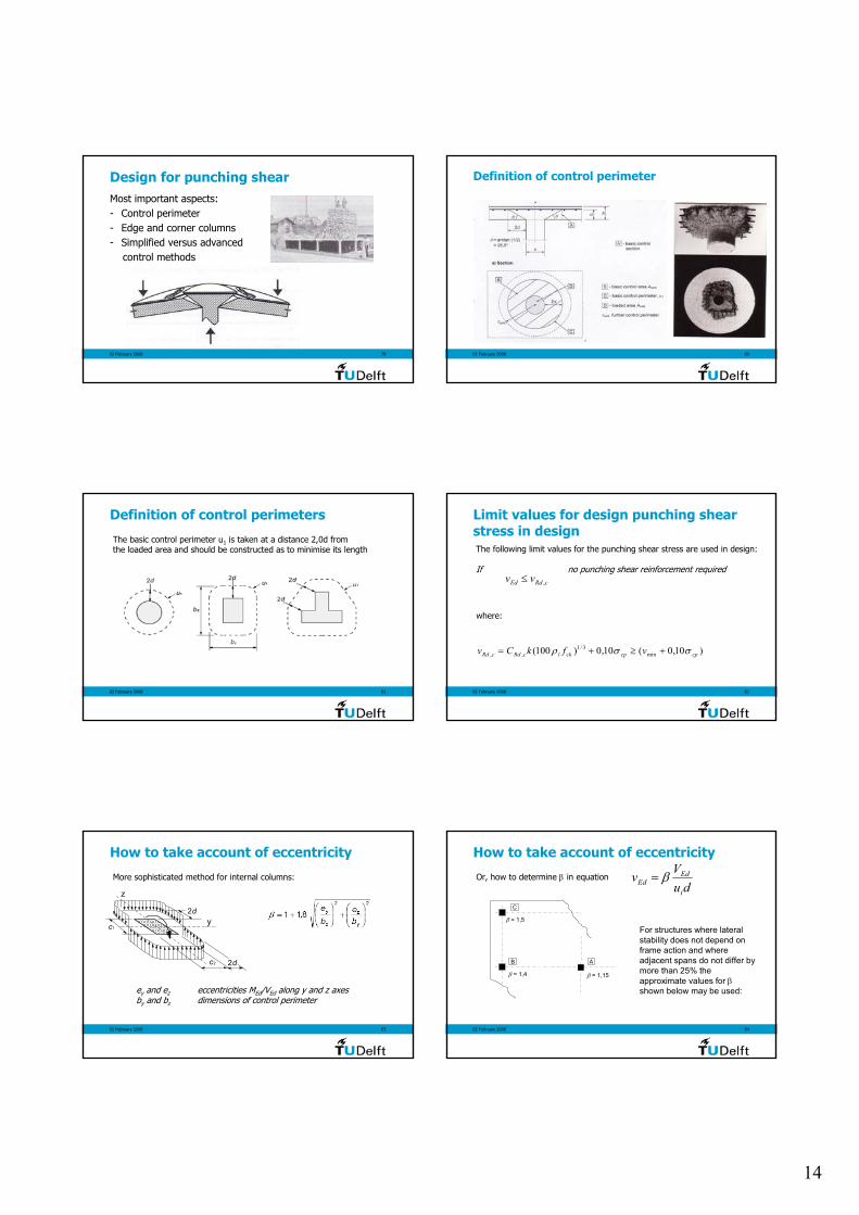
Modeling solid cross sections by equivalent thin-walled cross sections
Effective wall-thickness follows from tef,i=A/u, where;A = total area of cross section within outer circumference, including hollow areasU = outer circumference of the cross section
02 February 2008 74
Shear flow in any wall follows from:
k
Ediefit ATt2,, =τ
where
τt,I torsional shear stress in wall Itef,I effective wall thickness (A/u)TEd applied torsional momentAk area enclosed by centre lines
of connecting walls, includinghollow areas
Design procedure for torsion (1)
02 February 2008 75
Shear force VEd in wall i due to torsion is:
where
τt,I torsional shear stress in wall itef,I effective wall thickness (A/u)Zi inside length of wall I defined
by distance of intersectionpoints with adjacent walls
Design procedure for torsion (2)
iiefitiEd ztV ,,, τ=
02 February 2008 76
Design procedure for torsion (3)
The shear reinforcement in any wall can now be designed like a beamusing the variable angle truss analogy, with 1≤ cot θ ≤ 2,5
02 February 2008 77
Design procedure for torsion (4)
The longitudinal reinforcement in any wall follows from:
θcot2 k
Ed
k
ydsl
AT
ufA
=Σ
where
uk perimeter of area Akfyk design yield stress of steel θ angle of compression struts
02 February 2008
78
Punching shear
Prof.dr.ir. J.C. Walraven
Group Concrete Structures
14
02 February 2008 79
Design for punching shearMost important aspects:- Control perimeter- Edge and corner columns- Simplified versus advanced
control methods
02 February 2008 80
Definition of control perimeter
02 February 2008 81
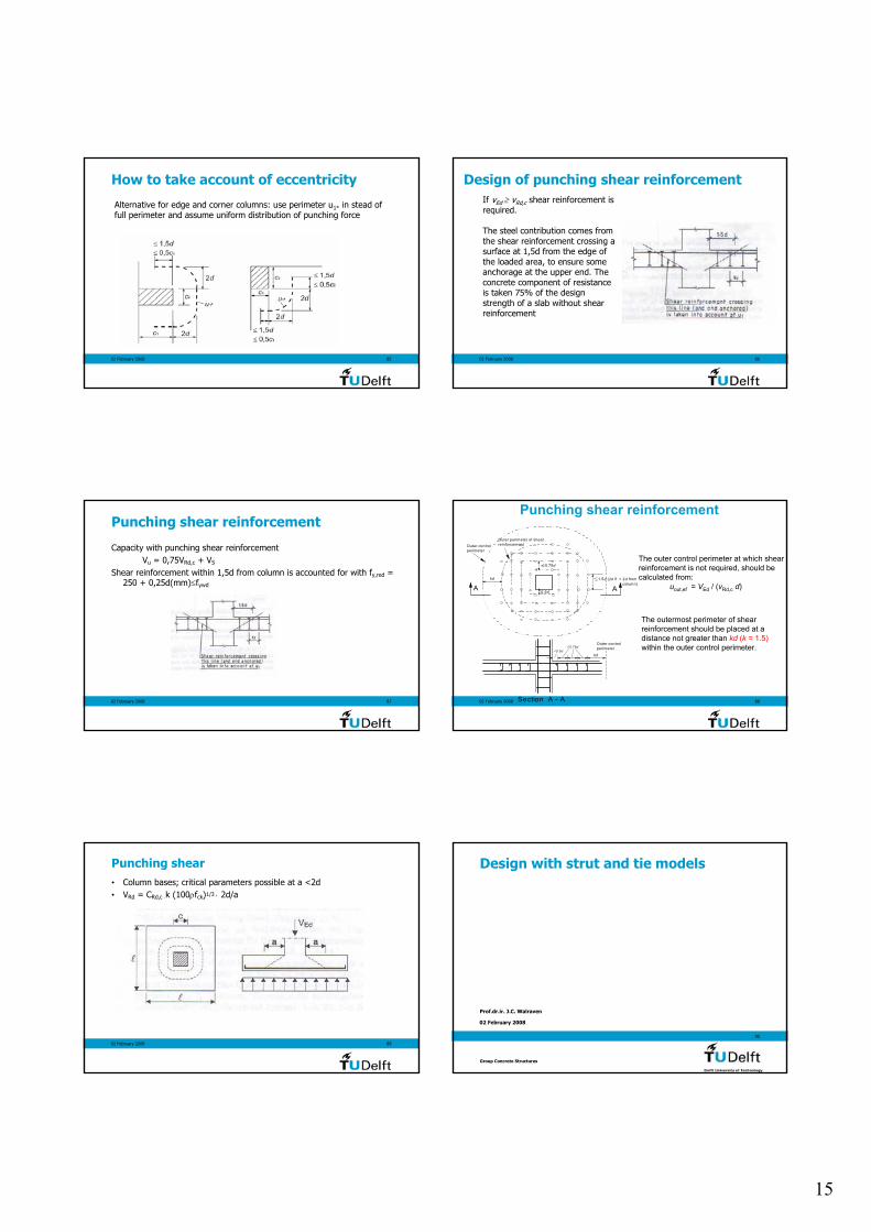
Definition of control perimeters
The basic control perimeter u1 is taken at a distance 2,0d from the loaded area and should be constructed as to minimise its length
02 February 2008 82
Limit values for design punching shear stress in design
cRdEd vv ,≤
The following limit values for the punching shear stress are used in design:
If no punching shear reinforcement required
)10,0(10,0)100( min3/1
,, cpcpcklcRdcRd vfkCv σσρ +≥+=
where:
02 February 2008 83
How to take account of eccentricity
More sophisticated method for internal columns:
c1
c2
2d
2d
y
z
ey and ez eccentricities MEd/VEd along y and z axesby and bz dimensions of control perimeter
02 February 2008 84
How to take account of eccentricity
duVvi
EdEd β=Or, how to determine β in equation
β = 1,4
β = 1,5
β = 1,15
C
B A
For structures where lateral stability does not depend on frame action and where adjacent spans do not differ by more than 25% the approximate values for βshown below may be used:
15
02 February 2008 85
How to take account of eccentricity
Alternative for edge and corner columns: use perimeter u1* in stead offull perimeter and assume uniform distribution of punching force
02 February 2008 86
Design of punching shear reinforcementIf vEd ≥ vRd,c shear reinforcement is required.
The steel contribution comes from the shear reinforcement crossing a surface at 1,5d from the edge of the loaded area, to ensure some anchorage at the upper end. The concrete component of resistance is taken 75% of the design strength of a slab without shear reinforcement
02 February 2008 87
Punching shear reinforcement
Capacity with punching shear reinforcementVu = 0,75VRd,c + VS
Shear reinforcement within 1,5d from column is accounted for with fy,red = 250 + 0,25d(mm)≤fywd
02 February 2008 88
kd
Outer controlperimeter
Outer perimeter of shearreinforcement
1.5d (2d if > 2d from column)
0.75d
0.5dA A
Section A - A
0.75d0.5d
Outer controlperimeter
kd
Punching shear reinforcement
The outer control perimeter at which shear reinforcement is not required, should be calculated from:
uout,ef = VEd / (vRd,c d)
The outermost perimeter of shear reinforcement should be placed at a distance not greater than kd (k = 1.5) within the outer control perimeter.
02 February 2008 89
Punching shear• Column bases; critical parameters possible at a <2d• VRd = CRd,c ⋅k (100ρfck)1/3 ⋅ 2d/a
02 February 2008
90
Design with strut and tie models
Prof.dr.ir. J.C. Walraven
Group Concrete Structures
16
02 February 2008 91
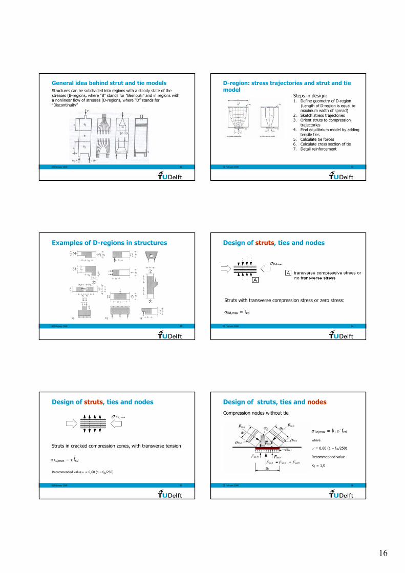
General idea behind strut and tie modelsStructures can be subdivided into regions with a steady state of the stresses (B-regions, where “B” stands for “Bernoulii” and in regions with a nonlinear flow of stresses (D-regions, where “D” stands for “Discontinuity”
02 February 2008 92
D-region: stress trajectories and strut and tie model
Steps in design:1. Define geometry of D-region
(Length of D-region is equal to maximum width of spread)
2. Sketch stress trajectories3. Orient struts to compression
trajectories4. Find equilibrium model by adding
tensile ties5. Calculate tie forces6. Calculate cross section of tie7. Detail reinforcement
02 February 2008 93
Examples of D-regions in structures
02 February 2008 94
Design of struts, ties and nodes
Struts with transverse compression stress or zero stress:
σRd,max = fcd
02 February 2008 95
Design of struts, ties and nodes
Struts in cracked compression zones, with transverse tension
σRd,max = υfcd
Recommended value υ = 0,60 (1 – fck/250)
02 February 2008 96
Design of struts, ties and nodes
Compression nodes without tie
σRd,max = k1 υ’ fcd
where
υ’ = 0,60 (1 – fck/250)
Recommended value
K1 = 1,0
17
02 February 2008 97
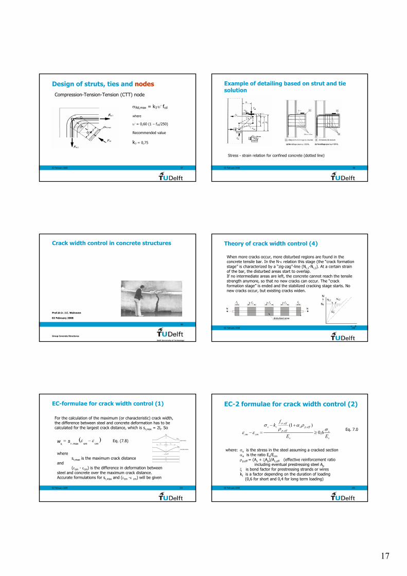
Design of struts, ties and nodesCompression-Tension-Tension (CTT) node
σRd,max = k3 υ’ fcd
where
υ’ = 0,60 (1 – fck/250)
Recommended value
k3 = 0,75
02 February 2008 98
Example of detailing based on strut and tie solution
Stress - strain relation for confined concrete (dotted line)
02 February 2008
99
Crack width control in concrete structures
Prof.dr.ir. J.C. Walraven
Group Concrete Structures
02 February 2008 100
Theory of crack width control (4)
When more cracks occur, more disturbed regions are found in the concrete tensile bar. In the N-ε relation this stage (the “crack formation stage” is characterized by a “zig-zag”-line (Nr,1-Nr,2). At a certain strain of the bar, the disturbed areas start to overlap.If no intermediate areas are left, the concrete cannot reach the tensile strength anymore, so that no new cracks can occur. The “crack formation stage” is ended and the stabilized cracking stage starts. No new cracks occur, but existing cracks widen.
lt lt2.lt 2.lt 2.lt
disturbed area
N N
Nr,1 Nr,2
N0
N
Nr
ε
02 February 2008 101
EC-formulae for crack width control (1)
For the calculation of the maximum (or characteristic) crack width,the difference between steel and concrete deformation has to be calculated for the largest crack distance, which is sr,max = 2lt. So
( )cmsmk
w rs max,εε −=
where sr,max is the maximum crack distance
and(εsm - εcm) is the difference in deformation between
steel and concrete over the maximum crack distance. Accurate formulations for sr,max and (εsm -ε cm) will be given
σsr
σse
steel stress
concrete stress
ctmf
lt lt
w
Eq. (7.8)
02 February 2008 102
EC-2 formulae for crack width control (2)
where: σs is the stress in the steel assuming a cracked sectionαe is the ratio Es/Ecmρp,eff = (As + ξAp)/Ac,eff (effective reinforcement ratio
including eventual prestressing steel Apξ is bond factor for prestressing strands or wireskt is a factor depending on the duration of loading
(0,6 for short and 0,4 for long term loading)
Eq. 7.0
s
s
s
effpeeffp
effctts
cmsm EE
fk
σρα
ρσ
εε 6,0)1( ,
,
,
≥+−
=−
18
02 February 2008 103
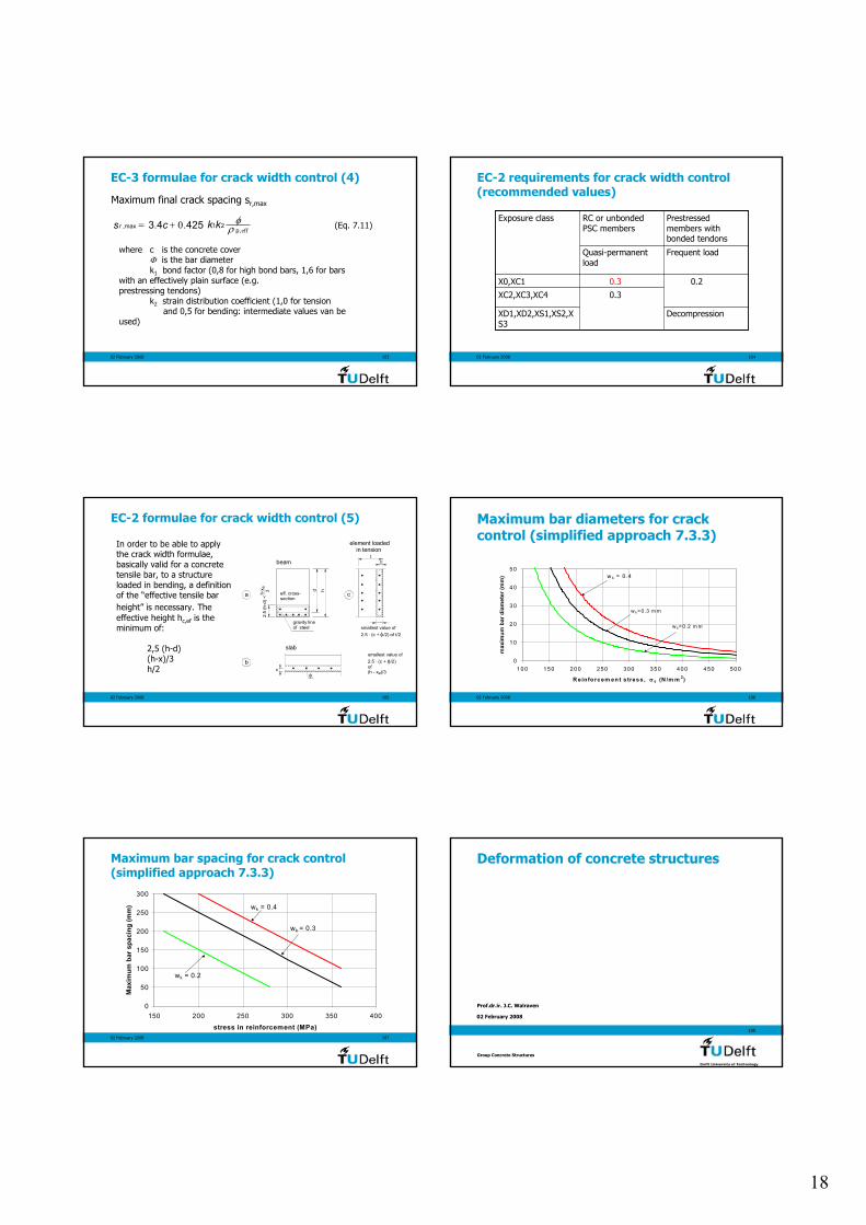
EC-3 formulae for crack width control (4)
Maximum final crack spacing sr,max
effpr kkcs
,21max, 425.04.3 ρ
φ+= (Eq. 7.11)
where c is the concrete coverΦ is the bar diameterk1 bond factor (0,8 for high bond bars, 1,6 for bars
with an effectively plain surface (e.g. prestressing tendons)
k2 strain distribution coefficient (1,0 for tensionand 0,5 for bending: intermediate values van be
used)
02 February 2008 104
EC-2 requirements for crack width control (recommended values)
DecompressionXD1,XD2,XS1,XS2,XS3
0.3XC2,XC3,XC4
0.20.3X0,XC1
Frequent loadQuasi-permanent load
Prestressed members with bonded tendons
RC or unbonded PSC members
Exposure class
02 February 2008 105
EC-2 formulae for crack width control (5)
In order to be able to apply the crack width formulae, basically valid for a concrete tensile bar, to a structure loaded in bending, a definition of the “effective tensile bar height” is necessary. The effective height hc,ef is the minimum of:
2,5 (h-d)(h-x)/3h/2
d h
gravity lineof steel
2.5
(h-d
) <h-
x e 3 eff. cross-section
beam
slab
element loaded in tension
ct
smallest value of2.5 . (c + /2) of t/2φ
cφ
smallest value of2.5 . (c + /2)of(h - x )/3
φ
e
a
b
c
02 February 2008 106
Maximum bar diameters for crack control (simplified approach 7.3.3)
0
1 0
2 0
3 0
4 0
5 0
10 0 1 50 20 0 250 3 00 35 0 40 0 4 50 50 0
R ein fo rcem en t s tres s , σ s (N /m m 2)
max
imum
bar
dia
met
er (m
m)
w k=0.3 m m
w k= 0.2 m m
w k = 0 .4
02 February 2008 107
Maximum bar spacing for crack control (simplified approach 7.3.3)
0
50
100
150
200
250
300
150 200 250 300 350 400
stress in reinforcement (MPa)
Max
imum
bar
spa
cing
(mm
) wk = 0.4
wk = 0.3
wk = 0.2
02 February 2008
108
Deformation of concrete structures
Prof.dr.ir. J.C. Walraven
Group Concrete Structures

19
02 February 2008 109
Deformation of concrete
Reason to worry or challenge for the future?
Deflection of ECC specimen, V. Li, University of Michigan
Damage in masonry wall due to excessive deflection of lintel
02 February 2008 110
Reasons for controling deflections (1)
Appearance
Deflections of such a magnitude that members appear visibly to sag will upset the owners or occupiers of structures. It is generally accepted that a deflection larger than span/250 should be avoided from the appearance point of view. A survey of structures in Germany that had given rise to complaints
produced 50 examples. The measured sag was less than span/250 in only two of these.
02 February 2008 111
Reasons for controling deflections (2)
Damage to non-structural Members
An important consequence of excessive deformation is damage to non structural members, like partition walls. Since partition walls are unreinforced and brittle, cracks can be large (several millimeters). The most commonly specified limit deflection is span/500, for deflection occurring after construction of the partitions. It should be assumed that all quasi permanent loading starts at the same time.
02 February 2008 112
Reasons for controling deflections (3)
Collapse
In recent years many cases of collapse of flat roofs have been noted. If the rainwater pipes have a too low capacity, often caused by pollution and finally stoppage, the roof deflects more and more under the weight of the water and finally collapses. This occurs predominantly with light roofs. Concrete roofs are less susceptible for this type of damage
02 February 2008 113
EC-2 Control of deflections
Deflection limits according to chapter 7.4.1
• Under the quasi permanent load the deflection should not exceed span/250, in order to avoid impairment of appearance and general utility
• Under the quasi permanent loads the deflection should be limited to span/500 after construction to avoid damage to adjacent parts of the structure
02 February 2008 114
EC-2: SLS - Control of deflections
Control of deflection can bedone in two ways
- By calculation- By tabulated values
20
02 February 2008 115
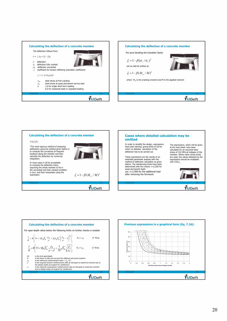
Calculating the deflection of a concrete member
The deflection follows from:
δ = ζ δII + (1 - ζ)δI
δ deflectionδI deflection fully crackedδII deflection uncrackedζ coefficient for tension stiffening (transition coefficient)
ζ = 1 - β (σsr/σs)2
σsr steel stress at first crackingσs steel stress at quasi permanent service loadβ 1,0 for single short-term loading
0,5 for sustained loads or repeated loading
02 February 2008 116
Calculating the deflection of a concrete member
2)/(1 rs σσβξ −=
For pure bending the transition factor
can as well be written as
2)/(1 MMcrβξ −=
where Mcr is the cracking moment and M is the applied moment
02 February 2008 117
Calculating the deflection of a concrete member
7.4.3 (7)
“The most rigorous method of assessing deflections using the method given before is to compute the curvatures at frequent locations along the member and then calculate the deflection by numerical integration.
2)/(1 MMcrβξ −=
In most cases it will be acceptable to compute the deflection twice, assuming the whole member to be in the uncracked and fully cracked condition in turn, and then interpolate using the expression:
02 February 2008 118
Cases where detailed calculation may be omittedIn order to simplify the design, expressions have been derived, giving limits of l/d for which no detailed calculation of the deflection has to be carried out.
These expressions are the results of an extended parameter analysis with the method of deflection calculation as given before. The slenderness limits have been determined with the criteria δ<L/250 for quasi permanent loadsand δ<L/500 for the additional load after removing the formwork
The expressions, which will be given at the next sheet, have been calculated for an assumed steel stress of 310 MPa at midspan of the member. Where other stress levels are used, the values obtained by the expressions should be multiplied with 310/σs
02 February 2008 119
Calculating the deflection of a concrete member
−++=
23
0ck
0ck 12,35,111
ρρ
ρρ ffK
dl if ρ ≤ ρ0 (7.16.a)
+
−+=
0ck
0ck
'121
'5,111
ρρ
ρρρ
ffKdl if ρ > ρ0 (7.16.b)
l/d is the limit span/depth K is the factor to take into account the different structural systemsρ0 is the reference reinforcement ratio = √fck 10-3
ρ is the required tension reinforcement ratio at mid-span to resist the moment due to the design loads (at support for cantilevers)
ρ’ is the required compression reinforcement ratio at mid-span to resist the moment due to design loads (at support for cantilevers)
For span-depth ratios below the following limits no further checks is needed
02 February 2008 120
Previous expressions in a graphical form (Eq. 7.16):
0
10
20
30
40
50
60
0 0.2 0.4 0.6 0.8 1 1.2 1.4 1.6 1.8 2
Reinforcement percentage (As/bd)
limiti
ng s
pan/
dept
h ra
tio
fck =30 40 50 60 70 80 90

21
02 February 2008 121
Lmit values for l/d below which no calculatedverification of the deflection is necessary
The table below gives the values of K (Eq.7.16), corresponding to the structural system. The table furthermore gives limit l/d values for a relatively high (ρ=1,5%) and low (ρ=0,5%) longitudinal reinforcement ratio. These values are calculated for concrete C30 and σs = 310 MPa and satisfy the deflection limits given in 7.4.1 (4) and (5).
l/d=20l/d=26l/d=30l/d=24l/d=8
l/d=14l/d=18l/d=20l/d=17l/d= 6
1,01,31,51,20,4
Simply supported slab/beamEnd spanInterior spanFlat slabCantilever
ρ = 1,5%ρ = 1,5%KStructural system
02 February 2008 122
Bond and anchorage
02 February 2008 123
Ultimate Bond Stress, fbd (8.4.2)
• The design value of the ultimate bond stress, fbd = 2,25 η1η2fctd where fctdshould be limited to C60/75
η1 =1 for ‘good’ and 0,7 for ‘poor’ bond conditionsη2 = 1 for φ ≤ 32, otherwise (132- φ)/100
a) 45º ≤ α ≤ 90º c) h > 250 mm
α
Direction of concreting
250
Direction of concreting
h
Direction of concreting
≥ 300
h
Direction of concreting
b) h ≤ 250 mm d) h > 600 mm
a) & b) ‘good’ bondconditions for all bars
c) & d) unhatched zone – ‘good’ bond conditionshatched zone - ‘poor’ bond conditions
02 February 2008 124
Basic Required Anchorage Length, lb,rqd(8.4.3)
• For bent bars lb,rqd should be measured along the centreline of the bar
lb,rqd = (φ / 4) (σsd / fbd)
where σsd is the design stress of the bar at the position from where the anchorage is measured
• Where pairs of wires/bars form welded fabrics φ should be replaced by φn = φ√2
02 February 2008 125
lbd = α1 α2 α3 α4 α5 lb,rqd ≥ lb,min
Design Anchorage Length, lbd (8.4.4)
α1 effect of bendsα2 effect of concrete coverα3 effect of confinement by transverse reinforcement (not welded)
α4 effect of confinement by welded transverse reinforcement
α5 effect of confinement by transverse pressure
For straight bars α1 = 1.0, otherwise 0.7α2 = 1- 0.15(cover - φ)/φ ≥ 0.7 and ≤ 1.0
α4 = 0.7
α5 = 1 - 0.04p ≥ 0.7 and ≤ 1.0where p is the transverse pressure (MPa) at ULS along lbd
α3 = 1- Kλ ≥ 0.7 and ≤ 1.0 where λ = (ΣAst - ΣAst,min)/As
K = 0.1 K = 0.05 K = 0
As , Asttφ stAs , AtφAs , Astt
(α2 α3 α5 ) ≥ 0.7 lb,min > max(0.3lb; 15φ, 100mm)02 February 2008 126
Design Lap Length, l0 (8.7.3)
l0 = α1 α2 α3 α5 α6 lb,rqd ≥ l0,min
α6 = (ρ1/25)0,5 but between 1,0 and 1,5where ρ1 is the % of reinforcement lapped within 0,65l0 from the centre of the lap
Note: Intermediate values may be determined by interpolation.
1,51,41,151α6
>50%50%33%< 25%Percentage of lapped bars relative to the total cross-section area
α1 α2 α3 α5 are as defined for anchorage length
l0,min ≥ max{0,3 α6 lb,rqd; 15φ; 200}
22
02 February 2008 127
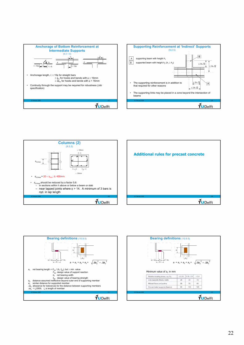
Anchorage of Bottom Reinforcement at Intermediate Supports
(9.2.1.5)
φ
lbd
φm
l ≥ 10φ l ≥ dm
φ
lbd
l ≥ 10φ
• Anchorage length, l, ≥ 10φ for straight bars≥ φm for hooks and bends with φ ≥ 16mm≥ 2φm for hooks and bends with φ < 16mm
• Continuity through the support may be required for robustness (Job specification)
02 February 2008 128
≤ h /31
≤ h /21
B
A
≤ h /32
≤ h /22
supporting beam with height h1
supported beam with height h2 (h1 ≥ h2)
• The supporting reinforcement is in addition to that required for other reasons
A
B
Supporting Reinforcement at ‘Indirect’ Supports(9.2.5)
• The supporting links may be placed in a zone beyond the intersection of beams
02 February 2008 129
Columns (2)(9.5.3)
• scl,tmax = 20 × φmin; b; 400mm
≤ 150mm
≤ 150mm
scl,tmax
• scl,tmax should be reduced by a factor 0,6:– in sections within h above or below a beam or slab– near lapped joints where φ > 14. A minimum of 3 bars is
rqd. in lap length02 February 2008 130
Additional rules for precast concrete
02 February 2008 131
a + ∆a2 2a1
aa + ∆a3 3
b1
a1
Bearing definitions (10.9.5)
a = a1 + a2 + a3 + 2 22 3a a∆ ∆+
a1 net bearing length = FEd / (b1 fRd), but ≥ min. valueFEd design value of support reactionb1 net bearing widthfRd design value of bearing strength
a2 distance assumed ineffective beyond outer end of supporting membera3 similar distance for supported member∆a2 allowance for tolerances for the distance between supporting members∆a3 = ln/2500, ln is length of member
02 February 2008 132
a + ∆a2 2a1
aa + ∆a3 3
b1
a1
Bearing definitions (10.9.5)
a = a1 + a2 + a3 + 2 22 3a a∆ ∆+
Minimum value of a1 in mm

23
02 February 2008 133
Pocket foundations(10.9.6)
ls
s
s
M
F
Fv
h
MF
v
Fh
h
F1
F2
F3
µF2
µF1
µF3
0,1l
0,1ll
l ≤ 1.2 hl ≤ s + l s
• detailing of reinforcement for F1 in top of pocket walls
Special attention should be paid to:
• shear resistance of column ends
• punching resistance of the footing slab under the column force
02 February 2008 134
Connections transmitting compressive forces
Concentrated bearing
Soft bearing
For soft bearings, in the absence of a more accurate analysis, the reinforcement may be taken as:
As = 0,25 (t/h) Fed/fyd
Where:t = padding thicknessh = dimension of padding in
direction of reinforcementFed = design compressive
force on connection
02 February 2008
135
Lightweight aggregate concrete
Prof.dr.ir. J.C. Walraven
Group Concrete Structures
02 February 2008 136
Lightweight concrete structures in the USA
Oronado bridge San Diego
Nappa bridge California 1977
52 m prestressed concrete beams, Lafayette USA
02 February 2008 137
Rilem Standard test
Raftsundet Bridge, Norway
Antioch Bridge california
02 February 2008 138
Qualification of lightweight aggregate concrete (LWAC)
Lightweight aggregate concrete is a concrete having a closed structure and an oven dry density of not more than 2200 kg/m3 consisting of or containing a proportion of artificial or natural lightweight aggregates having a density of less than 2000 kg/m3
24
02 February 2008 139
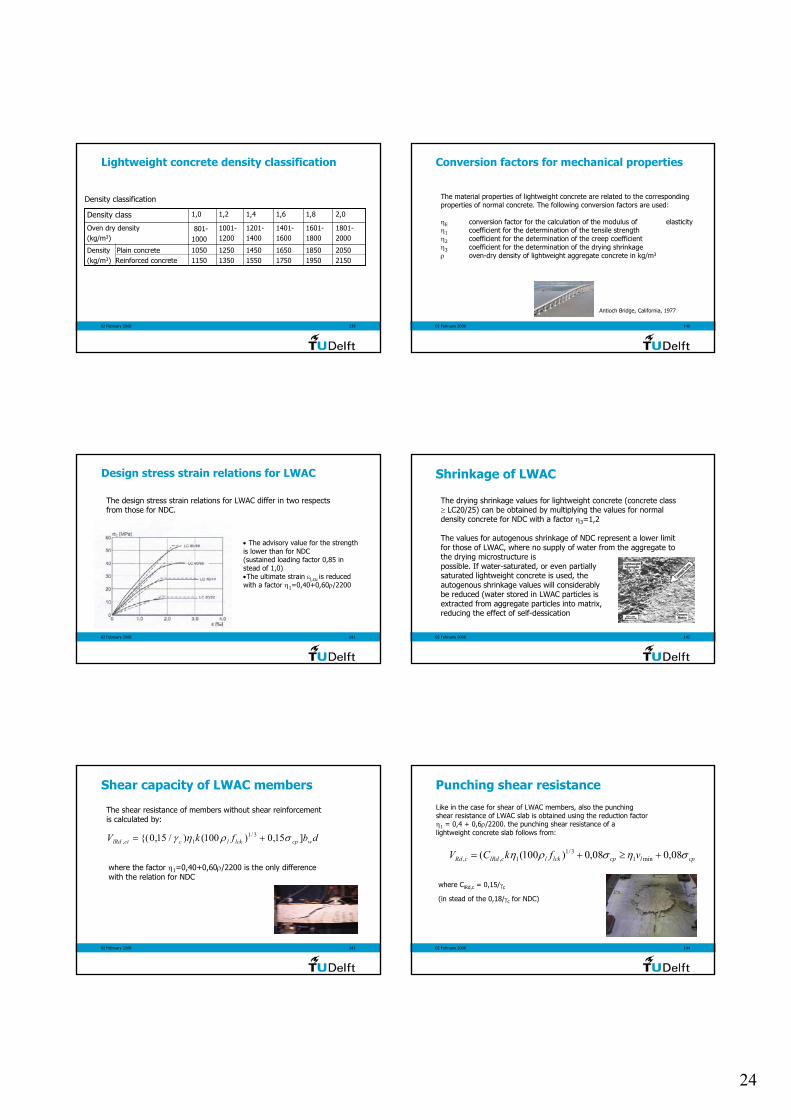
Lightweight concrete density classification
Density classification
20502150
18501950
16501750
14501550
12501350
10501150
Density Plain concrete(kg/m3) Reinforced concrete
1801-2000
1601-1800
1401-1600
1201-1400
1001-1200
801-1000
Oven dry density (kg/m3)
2,01,81,61,41,21,0Density class
02 February 2008 140
Conversion factors for mechanical properties
The material properties of lightweight concrete are related to the corresponding properties of normal concrete. The following conversion factors are used:
ηE conversion factor for the calculation of the modulus of elasticityη1 coefficient for the determination of the tensile strengthη2 coefficient for the determination of the creep coefficientη3 coefficient for the determination of the drying shrinkageρ oven-dry density of lightweight aggregate concrete in kg/m3
Antioch Bridge, California, 1977
02 February 2008 141
Design stress strain relations for LWAC
The design stress strain relations for LWAC differ in two respects from those for NDC.
• The advisory value for the strength is lower than for NDC(sustained loading factor 0,85 in stead of 1,0)•The ultimate strain εl,cu is reduced with a factor η1=0,40+0,60ρ/2200
02 February 2008 142
Shrinkage of LWAC
The drying shrinkage values for lightweight concrete (concrete class ≥ LC20/25) can be obtained by multiplying the values for normal density concrete for NDC with a factor η3=1,2
The values for autogenous shrinkage of NDC represent a lower limit for those of LWAC, where no supply of water from the aggregate to the drying microstructure is possible. If water-saturated, or even partiallysaturated lightweight concrete is used, the autogenous shrinkage values will considerably be reduced (water stored in LWAC particles isextracted from aggregate particles into matrix,reducing the effect of self-dessication
02 February 2008 143
Shear capacity of LWAC members
The shear resistance of members without shear reinforcement is calculated by:
dbfkV wcplcklcctlRd ]15,0)100()/15,0{( 3/11, σρηγ +=
where the factor η1=0,40+0,60ρ/2200 is the only difference with the relation for NDC
02 February 2008 144
Punching shear resistance
Like in the case for shear of LWAC members, also the punching shear resistance of LWAC slab is obtained using the reduction factor η1 = 0,4 + 0,6ρ/2200. the punching shear resistance of a lightweight concrete slab follows from:
cplcplcklclRdcRd vfkCV σησρη 08,008,0)100(( min13/1
1,, +≥+=
where ClRd,c = 0,15/γc
(in stead of the 0,18/γc for NDC)

25
02 February 2008
145
Plain and lightly reinforced concrete
Prof.dr.ir. J.C. Walraven
Group Concrete Structures
02 February 2008 146
Field of application
Members for which the effect of dynamic action may be ignored
• Members mainly subjected to compression other than due to prestressing, e.g. walls, columns, arches, vaults and tunnels
• Strip and pad footings for foundations• Retaining walls• Piles whose diameter is ≥ 600mm and where Ned/Ac≤ 0,3fck
02 February 2008 147
Additional design assumptions
12.3.1 Due to the less ductile properties of plain concrete, thedesign values should be reduced. The advisory reduction factor is 0,8
02 February 2008 148
ULS: design resistance to bending and axial failure
The axial resistance NRd, of a rectangular cross-section with a uniaxial eccentricity e, in the direction of hw, may be taken as:
NRd=ηfcd bh(1-2e/hw)
whereηfcd is the design compressive strength belonging to the block shaped stress-strain relation
02 February 2008 149
Shear
12.6.3 (1): “In plain concrete members account may be taken of the concrete tensile strength in the ultimate limit state for shear, provided that either by calculation or by experience brittle failure can be excluded and adequate resistance can be ensured”
Using Mohr’s circle it should be demonstrated that in nowhere in the structure the principal concrete tensile stress of the concrete exceeds the design tensile strength fctk
02 February 2008 150
Simplified design method for walls and columnsIn the absence of a more rigorous approach, the design resistance in terms of axial force slender wall or column in plain concrete may be calculated as follows:
NRd=b·hw·fcd·φ
where
NRd is the axial resistanceb is the overall width of the cross-sectionhw is the overall depth of the cross-sectionφ is a factor taking account eccentricity, including second
order effects
φ = 1,14·(1-2etot/hw) – 0,02 l0/hw ≤ (1 – 2etot/hw)

EN1992-2
G. Mancini Politecnico di Torino

1
EUROCODES - Background and Applications - Brussels 18-20 February 2008 Prof. Ing. Giuseppe Mancini - DISTR - Politecnico di Torino
1
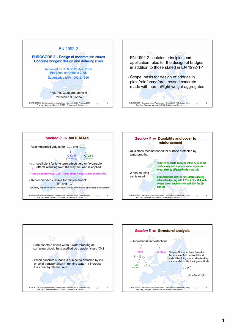
EN 1992-2
EUROCODE 2 EUROCODE 2 –– Design of concrete structuresDesign of concrete structuresConcrete bridges: design and detailing rulesConcrete bridges: design and detailing rules
Approved by CEN on 25 April 2005Published on October 2005
Supersedes ENV 1992-2:1996
Prof. Ing. Giuseppe ManciniPolitecnico di Torino
EUROCODES - Background and Applications - Brussels 18-20 February 2008 Prof. Ing. Giuseppe Mancini - DISTR - Politecnico di Torino
2
-EN 1992-2 contains principles and application rules for the design of bridges in addition to those stated in EN 1992-1-1
-Scope: basis for design of bridges in plain/reinforced/prestressed concrete made with normal/light weight aggregates
EUROCODES - Background and Applications - Brussels 18-20 February 2008 Prof. Ing. Giuseppe Mancini - DISTR - Politecnico di Torino
3
Section Section 3 3 ⇒⇒ MATERIALSMATERIALS
- Recommended values for Cmin and Cmax
C30/37 C70/85
- αcc coefficient for long term effects and unfavourable effects resulting from the way the load is applied
Recommended value: 0.85 → high stress values during construction
- Recommended classes for reinforcement:“B” and “C”
(Durability) (Ductility)
(Ductility reduction with corrosion / Ductility for bending and shear mechanisms)
EUROCODES - Background and Applications - Brussels 18-20 February 2008 Prof. Ing. Giuseppe Mancini - DISTR - Politecnico di Torino
4
Section Section 4 4 ⇒⇒ Durability Durability and cover and cover to to reinforcementreinforcement
- XC3 class recommended for surface protected by waterproofing
- When de-icing salt is used
Exposed concrete surfaces within (6 m) of the carriage way and supports under expansion joints: directly affected by de-icing salt
Recommended classes for surfaces directly affectd by de-icing salt: XD3 – XF2 – XF4, with covers given in tables 4.4N and 4.5N for XD classes
EUROCODES - Background and Applications - Brussels 18-20 February 2008 Prof. Ing. Giuseppe Mancini - DISTR - Politecnico di Torino
5
- Bare concrete decks without waterproofing or surfacing should be classified as abrasion class XM2
- When concrete surface is subject to abrasion by ice or solid transportation in running water → increase the cover by 10 mm, min
EUROCODES - Background and Applications - Brussels 18-20 February 2008 Prof. Ing. Giuseppe Mancini - DISTR - Politecnico di Torino
6
Section Section 5 5 ⇒⇒ Structural analysisStructural analysis
- Geometrical imperfections
Piers
0l nϑ ϑ α=
1/200(recom.)
2 1l ≤
Arches Shape of imperfections based on the shape of first horizontal and vertical buckling mode, idealised by a sinusoidal profile having amplitude
2lla ϑ=
(l = half wavelength)
2
EUROCODES - Background and Applications - Brussels 18-20 February 2008 Prof. Ing. Giuseppe Mancini - DISTR - Politecnico di Torino
7
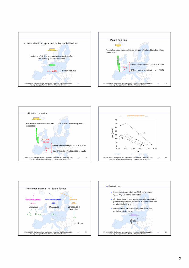
- Linear elastic analysis with limited redistributions
Limitation of δ due to uncertaintes on size effect and bending-shear interaction
(recommended value)δ ≥ 0.85
EUROCODES - Background and Applications - Brussels 18-20 February 2008 Prof. Ing. Giuseppe Mancini - DISTR - Politecnico di Torino
8
- Plastic analysis
Restrictions due to uncertaintes on size effect and bending-shear interaction:
0.15 for concrete strength classes ≤ C50/60≤ux
d 0.10 for concrete strength classes ≥ C55/67
EUROCODES - Background and Applications - Brussels 18-20 February 2008 Prof. Ing. Giuseppe Mancini - DISTR - Politecnico di Torino
9
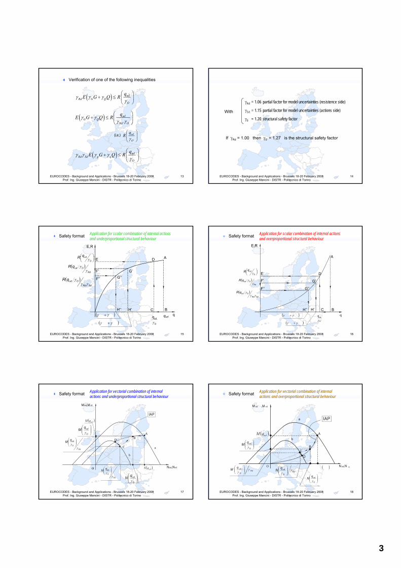
- Rotation capacity
0.30 for concrete strength classes ≤ C50/60≤ux
d 0.23 for concrete strength classes ≥ C55/67
in plastic hinges
Restrictions due to uncertaintes on size effect and bending-shear interaction:
EUROCODES - Background and Applications - Brussels 18-20 February 2008 Prof. Ing. Giuseppe Mancini - DISTR - Politecnico di Torino
10
Numerical rotation capacity
EUROCODES - Background and Applications - Brussels 18-20 February 2008 Prof. Ing. Giuseppe Mancini - DISTR - Politecnico di Torino
11
- Nonlinear analysis ⇒ Safety format
Reinforcing steel
1.1 fyk
Mean values
1.1 k fyk
Prestressing steel
1.1 fpk
Mean values
Concrete
γcf fck
Sargin modified mean values
γcf = 1.1 γs / γc
EUROCODES - Background and Applications - Brussels 18-20 February 2008 Prof. Ing. Giuseppe Mancini - DISTR - Politecnico di Torino
12
Design format
Incremental analysis from SLS, so to reachγG Gk + γQ Q in the same step
Continuation of incremental procedure up to the peak strength of the structure, in corrispondance of ultimate load qud
Evaluation of structural strength by use of a global safety factor γ0
0
udqR
γ⎛ ⎞⎜ ⎟⎝ ⎠
3
EUROCODES - Background and Applications - Brussels 18-20 February 2008 Prof. Ing. Giuseppe Mancini - DISTR - Politecnico di Torino
13
Verification of one of the following inequalities
( ) udRd G Q
O
qE G Q Rγ γ γ
γ⎛ ⎞
+ ≤ ⎜ ⎟⎝ ⎠
( ) .ud
G QRd O
qE G Q Rγ γ
γ γ⎛ ⎞
+ ≤ ⎜ ⎟⎝ ⎠
'
ud
O
qR
γ⎛ ⎞⎜ ⎟⎝ ⎠
( ) udRd Sd g q
O
qE G Q Rγ γ γ γ
γ⎛ ⎞
+ ≤ ⎜ ⎟⎝ ⎠
(i.e.)
EUROCODES - Background and Applications - Brussels 18-20 February 2008 Prof. Ing. Giuseppe Mancini - DISTR - Politecnico di Torino
14
With
γRd = 1.06 partial factor for model uncertainties (resistence side)
γSd = 1.15 partial factor for model uncertainties (actions side)
γ0 = 1.20 structural safety factor
If γRd = 1.00 then γ0’ = 1.27 is the structural safety factor
EUROCODES - Background and Applications - Brussels 18-20 February 2008 Prof. Ing. Giuseppe Mancini - DISTR - Politecnico di Torino
15
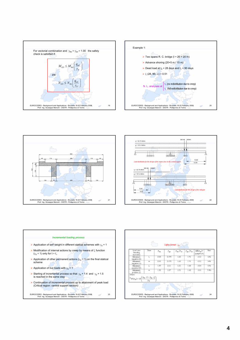
Safety format
A
BC
D E
F’’ G’’
H’’
E,R
qqud
O
udqγ
⎟⎠⎞⎜
⎝⎛
O
udqR γ
( )Rd
OudqRγ
γ
( )SdRd
OudqRγγ
γ
F’ G’
H’ ( )γγ +
( )γγ +
Application for scalar combination of internal actions and underproportional structural behaviour
EUROCODES - Background and Applications - Brussels 18-20 February 2008 Prof. Ing. Giuseppe Mancini - DISTR - Politecnico di Torino
16
Safety format Application for scalar combination of internal actions and overproportional structural behaviour
H’’
E,R
F’’
G’
E
C
qB
D
A
O
udqγ
⎟⎠⎞⎜
⎝⎛
O
udqR γ
( )Rd
OudqRγ
γ
( )SdRd
OudqRγγ
γ
F’
H’
G’’
( )γγ +
( )γγ +
EUROCODES - Background and Applications - Brussels 18-20 February 2008 Prof. Ing. Giuseppe Mancini - DISTR - Politecnico di Torino
17
Safety format Application for vectorial combination of internal actions and underproportional structural behaviour
M sd,M rd
C
Nsd,Nrd
BD
A
a
b
( )udqM
⎟⎟⎠
⎞⎜⎜⎝
⎛
O
udqNγ
( )udqN
⎟⎟⎠
⎞⎜⎜⎝
⎛
O
udqMγ
Rd
O
udqN
γγ ⎟⎟
⎠
⎞⎜⎜⎝
⎛
Rd
O
udqM
γγ ⎟⎟
⎠
⎞⎜⎜⎝
⎛
IAP
O
EUROCODES - Background and Applications - Brussels 18-20 February 2008 Prof. Ing. Giuseppe Mancini - DISTR - Politecnico di Torino
18
Safety format Application for vectorial combination of internal actions and overproportional structural behaviour
a
C
b
N sd,N rd
M sd ,M rd
B
D
A( )udqM
( )Rd
O
udqM γγ ⎟⎟
⎠
⎞⎜⎜⎝
⎛Rd
O
udqN γγ ⎟⎟
⎠
⎞⎜⎜⎝
⎛
⎟⎟⎠
⎞⎜⎜⎝
⎛
O
udqMγ
O
⎟⎟⎠
⎞⎜⎜⎝
⎛
O
udqNγ
IAP
4
EUROCODES - Background and Applications - Brussels 18-20 February 2008 Prof. Ing. Giuseppe Mancini - DISTR - Politecnico di Torino
19
For vectorial combination and γRd = γSd = 1.00 the safety check is satisfied if:
0 '
udED Rd
qM M
γ⎛ ⎞
≤ ⎜ ⎟⎝ ⎠
0 '
udED Rd
qN N
γ⎛ ⎞
≤ ⎜ ⎟⎝ ⎠
and
EUROCODES - Background and Applications - Brussels 18-20 February 2008 Prof. Ing. Giuseppe Mancini - DISTR - Politecnico di Torino
20
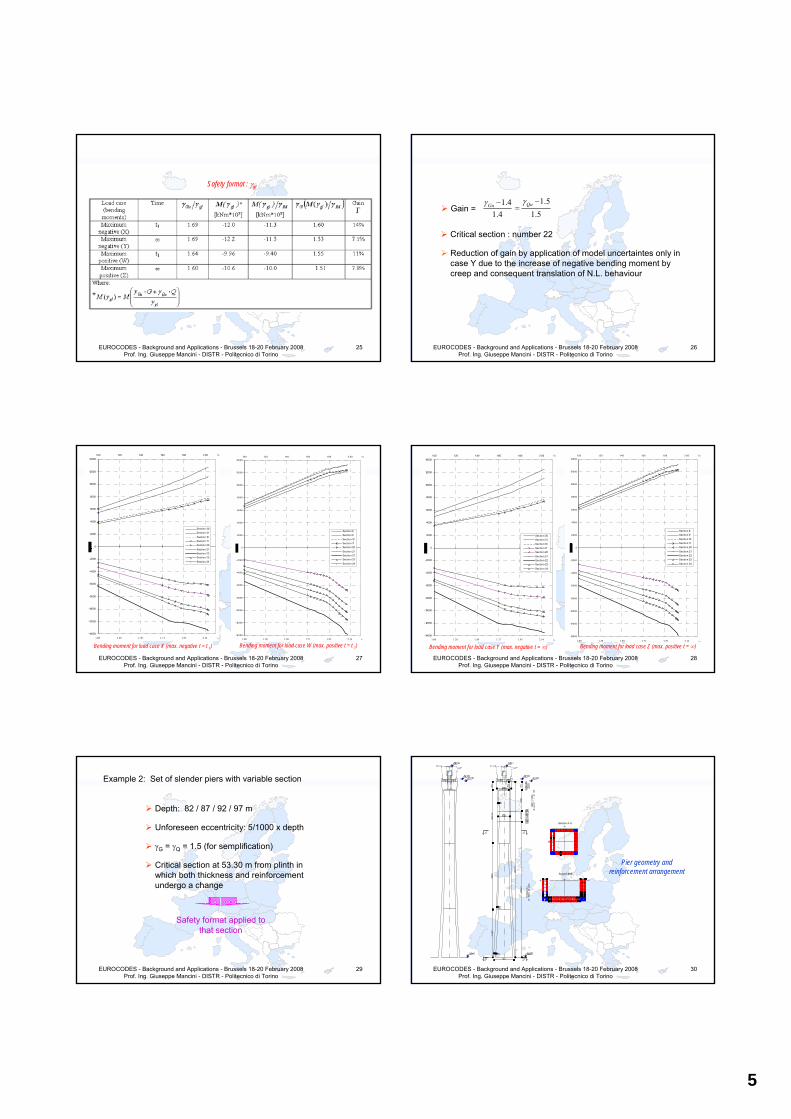
Example 1:
Two spans R. C. bridge (l = 20 + 20 m)
Advance shoring (20+5 m / 15 m)
Dead load at t0 = 28 days and t1 = 90 days
ξ (28, 90, ∞) = 0.51
N. L. analyses att1 (no redistribution due to creep)
t∞ (full redistribution due to creep)
EUROCODES - Background and Applications - Brussels 18-20 February 2008 Prof. Ing. Giuseppe Mancini - DISTR - Politecnico di Torino
21
60 115 300 115 60
650
50 50
3011
0140
300125 125
EUROCODES - Background and Applications - Brussels 18-20 February 2008 Prof. Ing. Giuseppe Mancini - DISTR - Politecnico di Torino
22
8 9 10 11 20 21 22 23 24 30 31
8,00
9,20
300 kN 300kNq = 32.75 kN/m
g = 101.4 kN/m
98 1110 31302423222120
300 kN 300kNq = 32.75 kN/m
g = 101.4 kN/m
10,80
12,00Load distribution for the design of the region close to the central support
Load distribution for the design of the midspan
EUROCODES - Background and Applications - Brussels 18-20 February 2008 Prof. Ing. Giuseppe Mancini - DISTR - Politecnico di Torino
23
Incremental loading process
Application of self weight in different statical schemes with γG = 1
Modification of internal actions by creep by means of ξ function(γG = 1) only for t = t∞
Application of other permanent actions (γG = 1) on the final statical scheme
Application of live loads with γG = 1
Starting of incremental process so that γG = 1.4 and γQ = 1.5 is reached in the same step
Continuation of incremental process up to attainment of peak load (Critical region: central support section)
EUROCODES - Background and Applications - Brussels 18-20 February 2008 Prof. Ing. Giuseppe Mancini - DISTR - Politecnico di Torino
24
Safety format : γGl
5
EUROCODES - Background and Applications - Brussels 18-20 February 2008 Prof. Ing. Giuseppe Mancini - DISTR - Politecnico di Torino
25
Safety format : γgl
EUROCODES - Background and Applications - Brussels 18-20 February 2008 Prof. Ing. Giuseppe Mancini - DISTR - Politecnico di Torino
26
Critical section : number 22
Reduction of gain by application of model uncertaintes only in case Y due to the increase of negative bending moment by creep and consequent translation of N.L. behaviour
Gain =1.51.4
1.4 1.5QuGu γγ −−
=
EUROCODES - Background and Applications - Brussels 18-20 February 2008 Prof. Ing. Giuseppe Mancini - DISTR - Politecnico di Torino
27
-14000
-12000
-10000
-8000
-6000
-4000
-2000
0
2000
4000
6000
8000
10000
12000
140001.00 1.20 1.40 1.60 1.80 2.00 γG
Section 30Section 31
Section 10Section 11Section 20
Section 21Section 22Section 23
Section 24
1.00 1.28 1.50 1.71 1.93 2.14 γQ
Bending moment for load case X (max. negative t = t 1)
-14000
-12000
-10000
-8000
-6000
-4000
-2000
0
2000
4000
6000
8000
10000
12000
140001.00 1.20 1.40 1.60 1.80 2.00 γG
Section 8Section 9Section 10Section 11Section 20
Section 21Section 22Section 23Section 24
1.00 1.28 1.50 1.71 1.93 2.14 γQ
Bending moment for load case W (max. positive t = t 1)
EUROCODES - Background and Applications - Brussels 18-20 February 2008 Prof. Ing. Giuseppe Mancini - DISTR - Politecnico di Torino
28
-14000
-12000
-10000
-8000
-6000
-4000
-2000
0
2000
4000
6000
8000
10000
12000
140001.00 1.20 1.40 1.60 1.80 2.00 γG
Section 30Section 31
Section 10Section 11Section 20
Section 21Section 22Section 23
Section 24
1.00 1.28 1.50 1.71 1.93 2.14 γQ
Bending moment for load case Y (max. negative t = ∞)
-14000
-12000
-10000
-8000
-6000
-4000
-2000
0
2000
4000
6000
8000
10000
12000
140001.00 1.20 1.40 1.60 1.80 2.00 γG
Section 8Section 9
Section 10Section 11Section 20
Section 21Section 22Section 23
Section 24
1.00 1.28 1.50 1.71 1.93 2.14 γQ
Bending moment for load case Z (max. positive t = ∞)
EUROCODES - Background and Applications - Brussels 18-20 February 2008 Prof. Ing. Giuseppe Mancini - DISTR - Politecnico di Torino
29
Example 2: Set of slender piers with variable section
Depth: 82 / 87 / 92 / 97 m
Unforeseen eccentricity: 5/1000 x depth
γG = γQ = 1.5 (for semplification)
Critical section at 53.30 m from plinth in which both thickness and reinforcement undergo a change
Safety format applied to that section
EUROCODES - Background and Applications - Brussels 18-20 February 2008 Prof. Ing. Giuseppe Mancini - DISTR - Politecnico di Torino
30
Section A-A
Section B-B
Pier geometry and reinforcement arrangement
6
EUROCODES - Background and Applications - Brussels 18-20 February 2008 Prof. Ing. Giuseppe Mancini - DISTR - Politecnico di Torino
31
Safety format : γGl
EUROCODES - Background and Applications - Brussels 18-20 February 2008 Prof. Ing. Giuseppe Mancini - DISTR - Politecnico di Torino
32
Safety format : γgl
EUROCODES - Background and Applications - Brussels 18-20 February 2008 Prof. Ing. Giuseppe Mancini - DISTR - Politecnico di Torino
33
EUROCODES - Background and Applications - Brussels 18-20 February 2008 Prof. Ing. Giuseppe Mancini - DISTR - Politecnico di Torino
34
0.0E+00
5.0E+04
1.0E+05
1.5E+05
2.0E+05
2.5E+05
3.0E+05
3.5E+05
4.0E+05
-4.0E+05-3.5E+05-3.0E+05-2.5E+05-2.0E+05-1.5E+05-1.0E+05-5.0E+040.0E+00
Axial force N [kN]
Ben
ding
mom
ent [
kNm
]
Collapse surfacefor section1182 m Pier
87 m Pier
92 m Pier
97 m Pier
Safety format : γgl
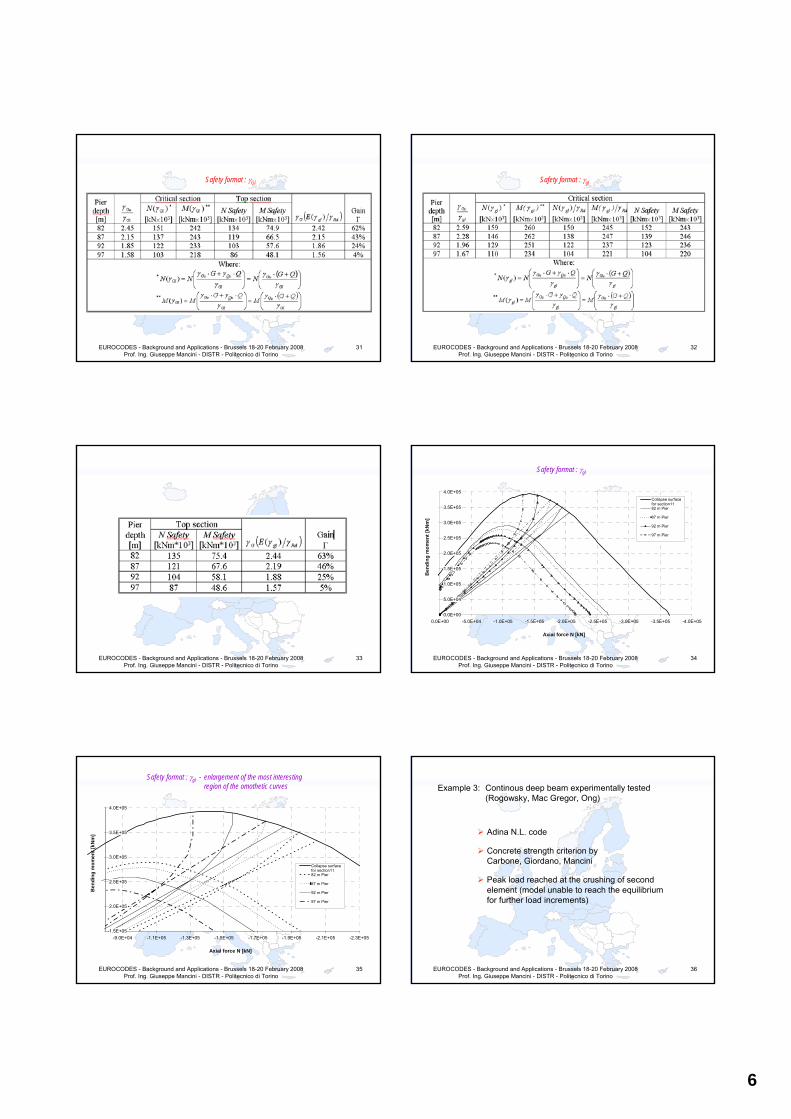
EUROCODES - Background and Applications - Brussels 18-20 February 2008 Prof. Ing. Giuseppe Mancini - DISTR - Politecnico di Torino
35
1.5E+05
2.0E+05
2.5E+05
3.0E+05
3.5E+05
4.0E+05
-2.3E+05-2.1E+05-1.9E+05-1.7E+05-1.5E+05-1.3E+05-1.1E+05-9.0E+04
Axial force N [kN]
Ben
ding
mom
ent [
kNm
]
Collapse surfacefor section1182 m Pier
87 m Pier
92 m Pier
97 m Pier
Safety format : γgl - enlargement of the most interesting region of the omothetic curves
EUROCODES - Background and Applications - Brussels 18-20 February 2008 Prof. Ing. Giuseppe Mancini - DISTR - Politecnico di Torino
36
Example 3: Continous deep beam experimentally tested (Rogowsky, Mac Gregor, Ong)
Adina N.L. code
Concrete strength criterion byCarbone, Giordano, Mancini
Peak load reached at the crushing of second element (model unable to reach the equilibrium for further load increments)
7
EUROCODES - Background and Applications - Brussels 18-20 February 2008 Prof. Ing. Giuseppe Mancini - DISTR - Politecnico di Torino
37
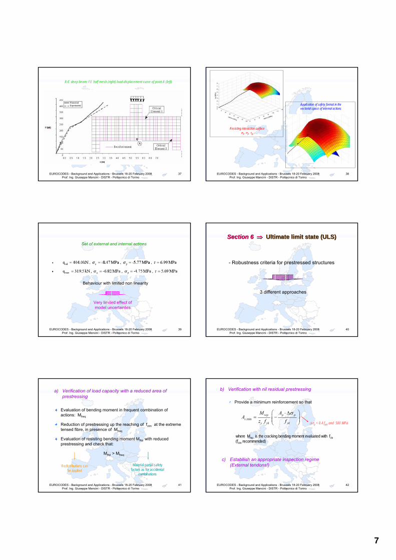
R/C deep beam: FE half mesh (right) load-displacement curve of point A (left)
EUROCODES - Background and Applications - Brussels 18-20 February 2008 Prof. Ing. Giuseppe Mancini - DISTR - Politecnico di Torino
38
Resisting interaction surfaceσx, σy, τxy
Application of safety format in the vectorial space of internal actions
EUROCODES - Background and Applications - Brussels 18-20 February 2008 Prof. Ing. Giuseppe Mancini - DISTR - Politecnico di Torino
39
Set of external and internal actions
Behaviour with limited non linearity
Very limited effect of model uncertaintes
EUROCODES - Background and Applications - Brussels 18-20 February 2008 Prof. Ing. Giuseppe Mancini - DISTR - Politecnico di Torino
40
Section Section 6 6 ⇒⇒ Ultimate Ultimate limit limit state (ULS)state (ULS)
- Robustness criteria for prestressed structures
3 different approaches
EUROCODES - Background and Applications - Brussels 18-20 February 2008 Prof. Ing. Giuseppe Mancini - DISTR - Politecnico di Torino
41
a) Verification of load capacity with a reduced area of prestressing
Evaluation of bending moment in frequent combination of actions: Mfreq
Reduction of prestressing up the reaching of fctm at the extreme tensed fibre, in presence of Mfreq
Evaluation of resisting bending moment MRd with reduced prestressing and check that:
MRd > Mfreq
Redistributions can be applied
Material partial safety factors as for accidental
combinations
EUROCODES - Background and Applications - Brussels 18-20 February 2008 Prof. Ing. Giuseppe Mancini - DISTR - Politecnico di Torino
42
b) Verification with nil residual prestressing
Provide a minimum reinforcement so that
,minrep p p
ss yk yk
M AA
z f fσ⎛ ⎞⋅ Δ
= −⎜ ⎟⎜ ⎟⎝ ⎠
where Mrep is the cracking bending moment evaluated with fctx(fctm recommended)
c) Estabilish an appropriate inspection regime (External tendons!)
Δσp < 0.4 fptk and 500 MPa
8
EUROCODES - Background and Applications - Brussels 18-20 February 2008 Prof. Ing. Giuseppe Mancini - DISTR - Politecnico di Torino
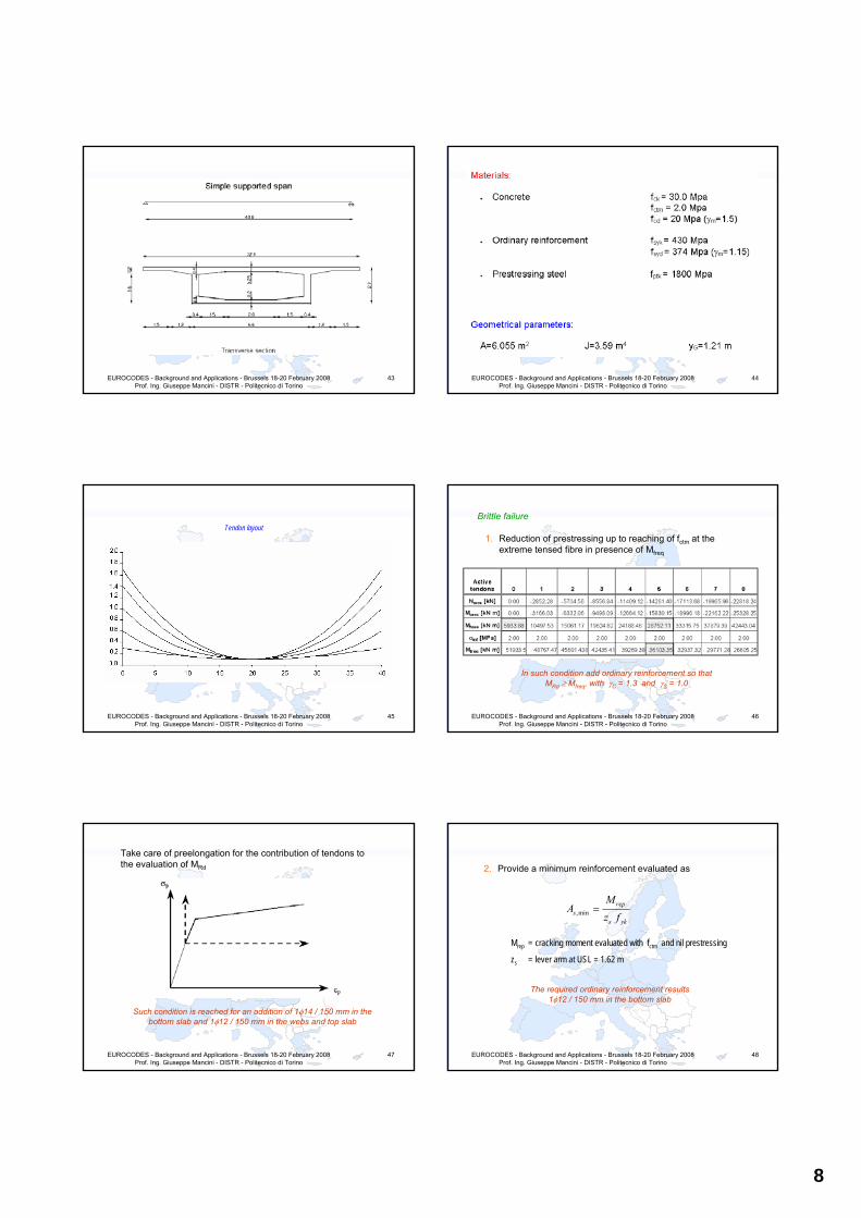
43
EUROCODES - Background and Applications - Brussels 18-20 February 2008 Prof. Ing. Giuseppe Mancini - DISTR - Politecnico di Torino
44
EUROCODES - Background and Applications - Brussels 18-20 February 2008 Prof. Ing. Giuseppe Mancini - DISTR - Politecnico di Torino
45
Tendon layout
EUROCODES - Background and Applications - Brussels 18-20 February 2008 Prof. Ing. Giuseppe Mancini - DISTR - Politecnico di Torino
46
Brittle failure
1. Reduction of prestressing up to reaching of fctm at the extreme tensed fibre in presence of Mfreq
In such condition add ordinary reinforcement so thatMRd ≥ Mfreq, with γC = 1.3 and γS = 1.0
EUROCODES - Background and Applications - Brussels 18-20 February 2008 Prof. Ing. Giuseppe Mancini - DISTR - Politecnico di Torino
47
Take care of preelongation for the contribution of tendons to the evaluation of MRd
Such condition is reached for an addition of 1φ14 / 150 mm in the bottom slab and 1φ12 / 150 mm in the webs and top slab
EUROCODES - Background and Applications - Brussels 18-20 February 2008 Prof. Ing. Giuseppe Mancini - DISTR - Politecnico di Torino
48
2. Provide a minimum reinforcement evaluated as
,minrep
ss yk
MA
z f=
Mrep = cracking moment evaluated with fctm and nil prestressing
zs = lever arm at USL = 1.62 m
The required ordinary reinforcement results1φ12 / 150 mm in the bottom slab
9
EUROCODES - Background and Applications - Brussels 18-20 February 2008 Prof. Ing. Giuseppe Mancini - DISTR - Politecnico di Torino
49
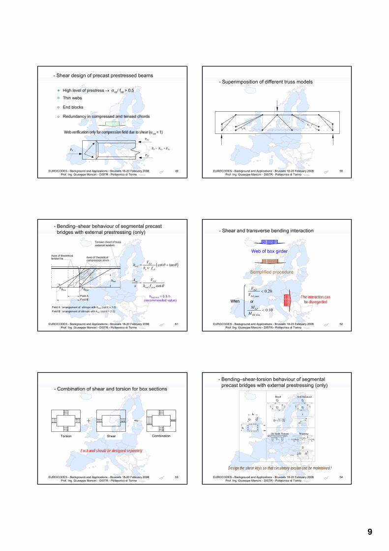
- Shear design of precast prestressed beams
High level of prestress → σcp/ fcd > 0.5
Thin webs
End blocks
Redundancy in compressed and tensed chords
Web verification only for compression field due to shear (αcw = 1)
Pd
Pd,c
Pd,t
Pd = Pd,c + Pd,t
EUROCODES - Background and Applications - Brussels 18-20 February 2008 Prof. Ing. Giuseppe Mancini - DISTR - Politecnico di Torino
50
- Superimposition of different truss models
θ1
θ2
EUROCODES - Background and Applications - Brussels 18-20 February 2008 Prof. Ing. Giuseppe Mancini - DISTR - Politecnico di Torino
51
Axes of theoretical tension tie Axes of theoretical
compression struts
Tension chord of truss (external tendon)
Field A Field B
θmin θmax
hred
Field A : arrangement of stirrups with θmax (cot θ = 1.0) Field B : arrangement of stirrups with θmin (cot θ = 2.5)
- Bending–shear behaviour of segmental precast bridges with external prestressing (only)
( )cot tanEdred
w cd
Vh
b fθ θ
ν= +
cotsw Ed
red ywd
A Vs h f θ
=
hred,min = 0.5 h(recommended value)
EUROCODES - Background and Applications - Brussels 18-20 February 2008 Prof. Ing. Giuseppe Mancini - DISTR - Politecnico di Torino
52
- Shear and transverse bending interaction
Web of box girder
Semplified procedure
When,max
0.20Ed
Rd
VV
<
,max
0.10Ed
Rd
MM
<
orThe interaction can
be disregarded
EUROCODES - Background and Applications - Brussels 18-20 February 2008 Prof. Ing. Giuseppe Mancini - DISTR - Politecnico di Torino
53
- Combination of shear and torsion for box sections
Torsion Shear Combination
Each wall should be designed separately
EUROCODES - Background and Applications - Brussels 18-20 February 2008 Prof. Ing. Giuseppe Mancini - DISTR - Politecnico di Torino
54
- Bending–shear-torsion behaviour of segmental precast bridges with external prestressing (only)
Qb 0 2h 0
Qb 0 2h 0 2
Q Q 2 Q
2
Qb 0 2h 0
2h 0 Qb 0 2 Q
D D Q 2 Qb 0 2h 0
2
2
D =
Bredt Self - balanced
Q Q
b0
h0
Q Q
De Saint Venant Warping
(1- α) Qb 0 b 0 (1 - α) Qb 0 b 0 (1- α) Qb 0 α Qb 0
≅
α ≅ 0
Design the shear keys so that circulatory torsion can be maintained !
10
EUROCODES - Background and Applications - Brussels 18-20 February 2008 Prof. Ing. Giuseppe Mancini - DISTR - Politecnico di Torino
55
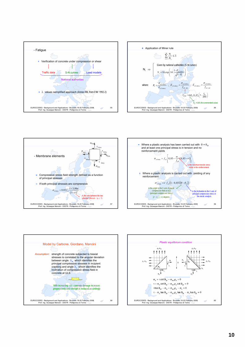
- Fatigue
Verification of concrete under compression or shear
Traffic data S-N curves Load models
National authorities
λ values semplified approach (Annex NN, from ENV 1992-2)
EUROCODES - Background and Applications - Brussels 18-20 February 2008 Prof. Ing. Giuseppe Mancini - DISTR - Politecnico di Torino
56
Application of Miner rule
11
mi
i i
nN=
≤∑
Ni ⇒Given by national authorities (S-N curves)
,max,110 exp 14
1
⎛ ⎞−⎜ ⎟= ⋅⎜ ⎟−⎝ ⎠
cd ii
i
EN
R
where: ,min,
,max,
cd ii
cd i
ER
E=
,min,,min,
,
cd icd i
cd fat
Ef
σ= ,max,
,max,,
cd icd i
cd fat
Ef
σ=; ;
( ) ⎛ ⎞= −⎜ ⎟⎝ ⎠
ff k β t f ckcd,fat 1 cc 0 cd 1
250
K1 =0.85 (Recommended value)
EUROCODES - Background and Applications - Brussels 18-20 February 2008 Prof. Ing. Giuseppe Mancini - DISTR - Politecnico di Torino
57
- Membrane elements
σ Edy
τ Edxy
τ Edxy
σ Edx
σ Edx
τ Edxy τ Edxy
σ Edy
Compressive stress field strength defined as a function of principal stresses
If both principal stresses are comprensive
( )max 2
1 3,800.851
cd cdf ασα
+=
+is the ratio between the twoprincipal stresses (α ≤ 1)
EUROCODES - Background and Applications - Brussels 18-20 February 2008 Prof. Ing. Giuseppe Mancini - DISTR - Politecnico di Torino
58
Where a plastic analysis has been carried out with θ = θeland at least one principal stress is in tension and no reinforcement yields
( )max 0,85 0,85scd cd
yd
ffσ
σ ν⎡ ⎤
= − −⎢ ⎥⎢ ⎥⎣ ⎦
is the maximum tensile stress value in the reinforcement
Where a plastic analysis is carried out with yielding of any reinforcement
( )max 1 0,032cd cd elfσ ν θ θ= − −
is the inclination to the X axis of principal compressive stress in
the elastic analysis
is the angle to the X axis of plastic compression field at ULS
(principal compressive stress)
15elθ θ− ≤ degrees
EUROCODES - Background and Applications - Brussels 18-20 February 2008 Prof. Ing. Giuseppe Mancini - DISTR - Politecnico di Torino
59
Model by Carbone, Giordano, Mancini
Assumption: strength of concrete subjected to biaxial stresses is correlated to the angular deviation between angle ϑel which identifies the principal compressive stresses in incipientcracking and angle ϑu which identifies the inclination of compression stress field in concrete at ULS
With increasing Δϑ concrete damage increases progressively and strength is reduced accordingly
EUROCODES - Background and Applications - Brussels 18-20 February 2008 Prof. Ing. Giuseppe Mancini - DISTR - Politecnico di Torino
60
Plastic equilibrium condition

11
EUROCODES - Background and Applications - Brussels 18-20 February 2008 Prof. Ing. Giuseppe Mancini - DISTR - Politecnico di Torino
61
0.00
0.05
0.10
0.15
0.20
0.25
0.30
0.35
0.40
0.45
0.50
0.0 10.0 20.0 30.0 40.0 50.0 60.0 70.0 80.0 90.0
θ pl
v Eq. 69
Eq. 70
Eq. 71
Eq. 72
Eq. 73
Graphical solution of inequalities system
ωx = 0.16ωy = 0.06nx = ny = -0.17ϑel = 45°
EUROCODES - Background and Applications - Brussels 18-20 February 2008 Prof. Ing. Giuseppe Mancini - DISTR - Politecnico di Torino
62
Resisting domain for vmax (a) and vmin (b)with ϑel=45°, ωx=ωy=0.3
EUROCODES - Background and Applications - Brussels 18-20 February 2008 Prof. Ing. Giuseppe Mancini - DISTR - Politecnico di Torino
63
Experimental versus calculated panel strenght by Marti and Kaufmann (a)and by Carbone, Giordano and Mancini (b)
EUROCODES - Background and Applications - Brussels 18-20 February 2008 Prof. Ing. Giuseppe Mancini - DISTR - Politecnico di Torino
64
Thickness = tr
τxyr
Y
σyr
θr
α β
σxr
σyr
σxr
τxyr
X
Skew reinforcement
Plates conventions
EUROCODES - Background and Applications - Brussels 18-20 February 2008 Prof. Ing. Giuseppe Mancini - DISTR - Politecnico di Torino
65
cosθr
ραr σsαr ar
θr
α σxr sinθr
β
ar β
br
sinθr
σyr cosθr τxyr cosθr
τxyr sinθr
ρβr σsβr br
α
1 Equilibrium of the section parallel to the compression
field
EUROCODES - Background and Applications - Brussels 18-20 February 2008 Prof. Ing. Giuseppe Mancini - DISTR - Politecnico di Torino
66
sinθr
α
cosθr
σxr cosθr
τxyr cosθr
θr
ρβr σsβr br’
β ar
’
br’
β
σyr sinθr
α
τxyr sinθr
ραr σsαr ar’
σcr
1
Equilibrium of the section orthogonal to
the compression field
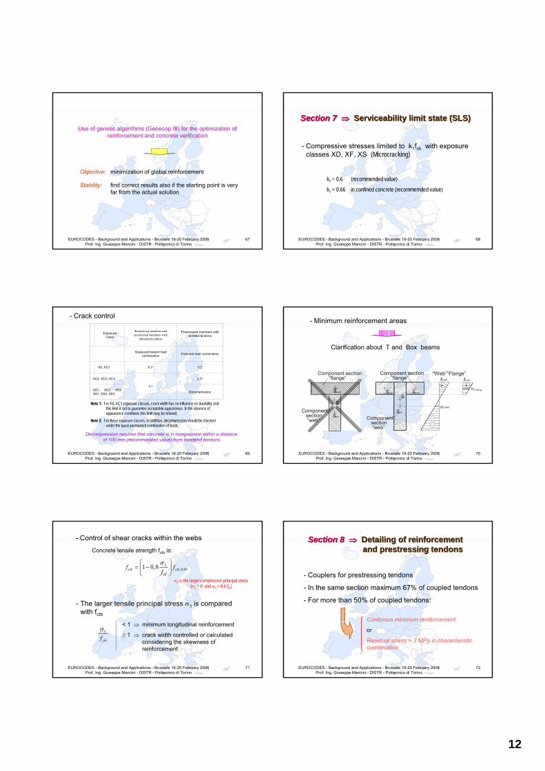
12
EUROCODES - Background and Applications - Brussels 18-20 February 2008 Prof. Ing. Giuseppe Mancini - DISTR - Politecnico di Torino
67
Use of genetic algorithms (Genecop III) for the optimization of reinforcement and concrete verification
Objective: minimization of global reinforcement
Stability: find correct results also if the starting point is very far from the actual solution
EUROCODES - Background and Applications - Brussels 18-20 February 2008 Prof. Ing. Giuseppe Mancini - DISTR - Politecnico di Torino
68
Section Section 7 7 ⇒⇒ Serviceability limit Serviceability limit state (SLS)state (SLS)
- Compressive stresses limited to k1fck with exposure classes XD, XF, XS (Microcracking)
k1 = 0.6 (recommended value)
k1 = 0.66 in confined concrete (recommemded value)
EUROCODES - Background and Applications - Brussels 18-20 February 2008 Prof. Ing. Giuseppe Mancini - DISTR - Politecnico di Torino
69
ExposureClass
Reinforced members and prestressed members with
unbonded tendons
Prestressed members with bonded tendons
Quasi-permanent load combination Frequent load combination
X0, XC1 0,31 0,2
XC2, XC3, XC4
0,3
0,22
XD1, XD2, XD3 XS1, XS2, XS3 Decompression
Note 1: For X0, XC1 exposure classes, crack width has no influence on durability and this limit is set to guarantee acceptable appearance. In the absence of appearance conditions this limit may be relaxed.
Note 2: For these exposure classes, in addition, decompression should be checked under the quasi-permanent combination of loads.
- Crack control
Decompression requires that concrete is in compression within a distanceof 100 mm (recommended value) from bondend tendons
EUROCODES - Background and Applications - Brussels 18-20 February 2008 Prof. Ing. Giuseppe Mancini - DISTR - Politecnico di Torino
70
- Minimum reinforcement areas
f ct,eff fct,eff
“Web”“Flange”
σc,web
σc,flange
Component section“flange”
Componentsection “web”
S flange
S web Componentsection“web”
Sweb
Sm
Component section “flange”
+ +
S m S flange Sflange
Clarification about T and Box beams
EUROCODES - Background and Applications - Brussels 18-20 February 2008 Prof. Ing. Giuseppe Mancini - DISTR - Politecnico di Torino
71
- Control of shear cracks within the webs
Concrete tensile strength fctb is:
3,0.051 0,8
σ⎛ ⎞= −⎜ ⎟
⎝ ⎠ctb ctk
ck
f ff
σ3 is the larger compressive principal stress(σ3 > 0 and σ3 < 0.6 fck)
- The larger tensile principal stress σ1 is compared with fctb
< 1 ⇒ minimum longitudinal reinforcement
≥ 1 ⇒ crack width controlled or calculated considering the skewness of reinforcement
1
ctbfσ
EUROCODES - Background and Applications - Brussels 18-20 February 2008 Prof. Ing. Giuseppe Mancini - DISTR - Politecnico di Torino
72
Section Section 8 8 ⇒⇒ Detailing Detailing of of reinforcement reinforcement and and prestressing tendonsprestressing tendons
- Couplers for prestressing tendons
- In the same section maximum 67% of coupled tendons
- For more than 50% of coupled tendons:
Continous minimum reinforcement
or
Residual stress > 3 MPa in characteristic combination
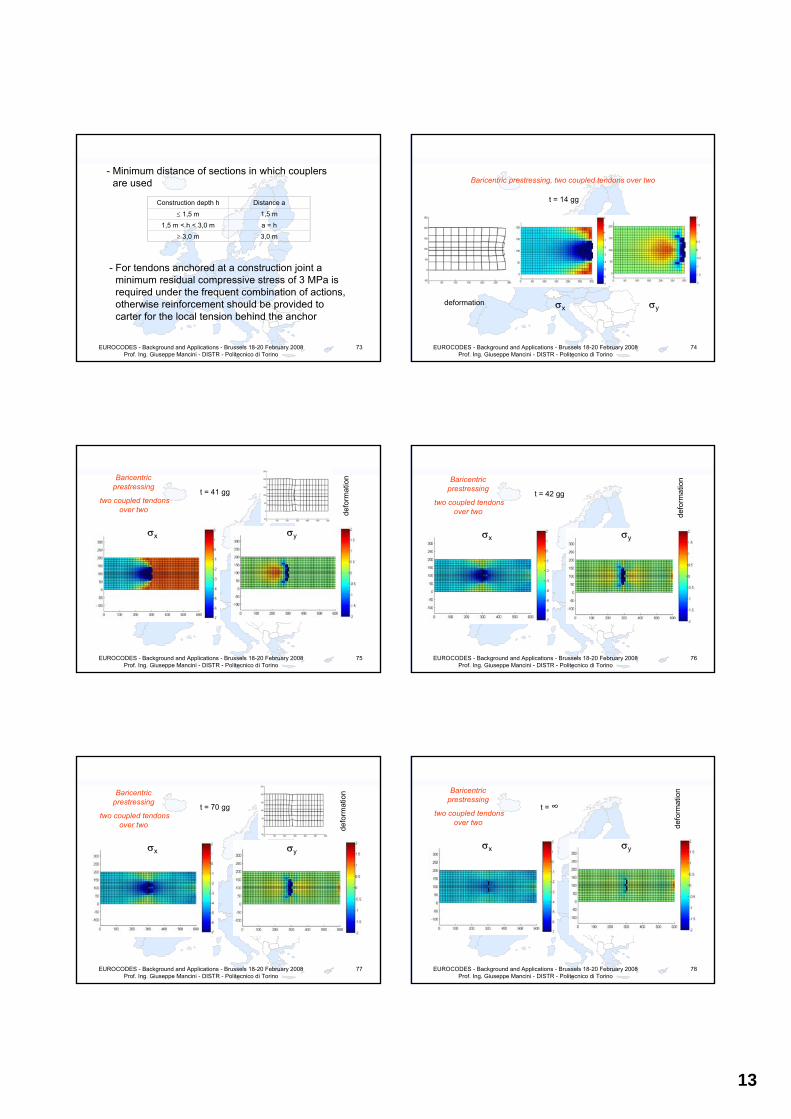
13
EUROCODES - Background and Applications - Brussels 18-20 February 2008 Prof. Ing. Giuseppe Mancini - DISTR - Politecnico di Torino
73
- Minimum distance of sections in which couplers are used
Construction depth h Distance a
≤ 1,5 m 1,5 m1,5 m < h < 3,0 m a = h
≥ 3,0 m 3,0 m
- For tendons anchored at a construction joint a minimum residual compressive stress of 3 MPa is required under the frequent combination of actions, otherwise reinforcement should be provided to carter for the local tension behind the anchor
EUROCODES - Background and Applications - Brussels 18-20 February 2008 Prof. Ing. Giuseppe Mancini - DISTR - Politecnico di Torino
74
Baricentric prestressing, two coupled tendons over two
t = 14 gg
deformation σx σy
EUROCODES - Background and Applications - Brussels 18-20 February 2008 Prof. Ing. Giuseppe Mancini - DISTR - Politecnico di Torino
75
Baricentric prestressing
two coupled tendons over two de
form
atio
n
t = 41 gg
σx σy
EUROCODES - Background and Applications - Brussels 18-20 February 2008 Prof. Ing. Giuseppe Mancini - DISTR - Politecnico di Torino
76
Baricentric prestressing
two coupled tendons over two de
form
atio
n
t = 42 gg
σx σy
EUROCODES - Background and Applications - Brussels 18-20 February 2008 Prof. Ing. Giuseppe Mancini - DISTR - Politecnico di Torino
77
Baricentric prestressing
two coupled tendons over two de
form
atio
n
t = 70 gg
σx σy
EUROCODES - Background and Applications - Brussels 18-20 February 2008 Prof. Ing. Giuseppe Mancini - DISTR - Politecnico di Torino
78
Baricentric prestressing
two coupled tendons over two de
form
atio
n
t = ∞
σx σy
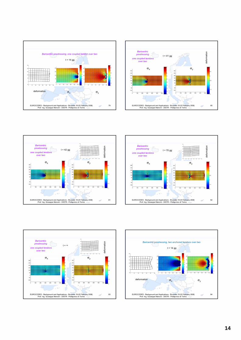
14
EUROCODES - Background and Applications - Brussels 18-20 February 2008 Prof. Ing. Giuseppe Mancini - DISTR - Politecnico di Torino
79
Baricentric prestressing, one coupled tendon over two
t = 14 gg
deformation σx σy
EUROCODES - Background and Applications - Brussels 18-20 February 2008 Prof. Ing. Giuseppe Mancini - DISTR - Politecnico di Torino
80
Baricentric prestressing
one coupled tendons over two
defo
rmat
ion
t = 41 gg
σx σy
EUROCODES - Background and Applications - Brussels 18-20 February 2008 Prof. Ing. Giuseppe Mancini - DISTR - Politecnico di Torino
81
Baricentric prestressing
one coupled tendons over two
defo
rmat
ion
t = 42 gg
σx σy
EUROCODES - Background and Applications - Brussels 18-20 February 2008 Prof. Ing. Giuseppe Mancini - DISTR - Politecnico di Torino
82
Baricentric prestressing
one coupled tendons over two de
form
atio
n
t = 70 gg
σx σy
EUROCODES - Background and Applications - Brussels 18-20 February 2008 Prof. Ing. Giuseppe Mancini - DISTR - Politecnico di Torino
83
Baricentric prestressing
one coupled tendons over two
defo
rmat
ion
t = ∞
σx σy
EUROCODES - Background and Applications - Brussels 18-20 February 2008 Prof. Ing. Giuseppe Mancini - DISTR - Politecnico di Torino
84
Baricentric prestressing, two anchored tendons over two
t = 14 gg
deformation σx σy
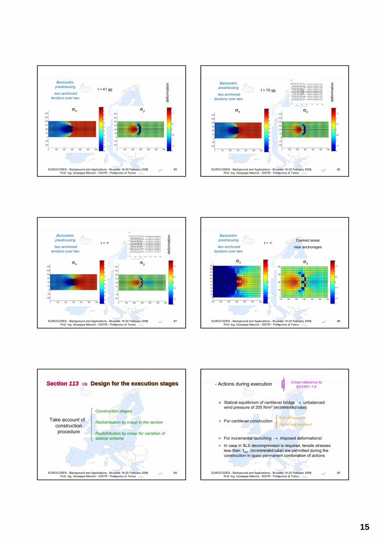
15
EUROCODES - Background and Applications - Brussels 18-20 February 2008 Prof. Ing. Giuseppe Mancini - DISTR - Politecnico di Torino
85
Baricentric prestressing
two anchored tendons over two
defo
rmat
ion
t = 41 gg
σx σy
EUROCODES - Background and Applications - Brussels 18-20 February 2008 Prof. Ing. Giuseppe Mancini - DISTR - Politecnico di Torino
86
Baricentric prestressing
two anchored tendons over two de
form
atio
n
t = 70 gg
σx σy
EUROCODES - Background and Applications - Brussels 18-20 February 2008 Prof. Ing. Giuseppe Mancini - DISTR - Politecnico di Torino
87
Baricentric prestressing
two anchored tendons over two de
form
atio
n
σx
t = ∞
σy
EUROCODES - Background and Applications - Brussels 18-20 February 2008 Prof. Ing. Giuseppe Mancini - DISTR - Politecnico di Torino
88
Baricentric prestressing
two anchored tendons over two
σx
t = ∞
σy
Zoomed areas
near anchorages
EUROCODES - Background and Applications - Brussels 18-20 February 2008 Prof. Ing. Giuseppe Mancini - DISTR - Politecnico di Torino
89
Section Section 113 113 ⇒⇒ Design Design for for the the execution stagesexecution stages
Take account of construction procedure
Construction stages
Redistribution by creep in the section
Redistribution by creep for variation of statical scheme
EUROCODES - Background and Applications - Brussels 18-20 February 2008 Prof. Ing. Giuseppe Mancini - DISTR - Politecnico di Torino
90
- Actions during execution Cross reference to EN1991-1-6
Statical equilibrium of cantilever bridge → unbalanced wind pressure of 200 N/m2 (recommended value)
For cantilever constructionFall of formwork
Fall of one segment
For incremental launching → Imposed deformations!
In case in SLS decompression is required, tensile stresses less then fctm (recommended value) are permitted during the construction in quasi-permanent combination of actions

16
EUROCODES - Background and Applications - Brussels 18-20 February 2008 Prof. Ing. Giuseppe Mancini - DISTR - Politecnico di Torino
91
Annex Annex B B ⇒⇒ Creep Creep and and shrinkage strainshrinkage strain
HPC, class R cement, strength ≥ 50/60 MPa with or without silica fume
Thick members → kinetic of basic creep and dryingcreep is different
Autogenous shrinkage:related to process of hydratation
Drying shrinkage:related to humidity exchanges
Distiction between
Specific formulae for SFC (content > 5% of cement by weight)
EUROCODES - Background and Applications - Brussels 18-20 February 2008 Prof. Ing. Giuseppe Mancini - DISTR - Politecnico di Torino
92
- Autogenous shrinkage
For t < 28 days fctm(t) / fck is the main variable
( )0.1cm
ck
f tf
≥ ( ) ( ) 6( ), 20 2.2 0.2 10cm
ca ck ckck
f tt f f
fε −⎛ ⎞
= − −⎜ ⎟⎝ ⎠
( )0.1cm
ck
f tf
< ( ), 0ca ckt fε =
For t ≥ 28 days
[ ] 6( , ) ( 20) 2.8 1.1exp( / 96) 10ca ck ckt f f tε −= − − −
97% of total autogenous shrinkage occurs within 3 mounths
EUROCODES - Background and Applications - Brussels 18-20 February 2008 Prof. Ing. Giuseppe Mancini - DISTR - Politecnico di Torino
93
- Drying shrinkage (RH ≤ 80%)
( ) 6
0 20
K( ) 72exp( 0.046 ) 75 10( , , , , )
( )ck ck s
cd s cks cd
f f RH t tt t f h RH
t t hε
β
−− + − −⎡ ⎤⎣ ⎦=− +
with: ( ) 18ckK f = if fck ≤ 55 MPa
( ) 30 0.21ck ckK f f= − if fck > 55 MPa
⎜⎜⎝
⎛−−
=concretefumesilicanonforconcretefumesilicafor
cd 021.0007.0
β
EUROCODES - Background and Applications - Brussels 18-20 February 2008 Prof. Ing. Giuseppe Mancini - DISTR - Politecnico di Torino
94
- Creep
( ) ( ) ( ) ( )00 0 0
28
, , ,cc b dc
tt t t t t t
Eσ
ε ⎡ ⎤= Φ + Φ⎣ ⎦
Basic creep Drying creep
EUROCODES - Background and Applications - Brussels 18-20 February 2008 Prof. Ing. Giuseppe Mancini - DISTR - Politecnico di Torino
95
- Basic creep
( )( ) 00 0 0
0
, , ,b ck cm b
bc
t tt t f f t
t tφ
β
−Φ =
⎡ ⎤− +⎣ ⎦
( ) 0,37
cm 0b0
3.6 for silica fume concretef t
1.4 for non silica fume concrete
φ
⎛ −⎜⎜=⎜⎜ −⎝
( )
( )
cm 0
ck
bc
cm 0
ck
f t0.37exp 2.8 for silica fume concretef
f t0.4exp 3.1 for non silica fume concretef
β
⎛ ⎛ ⎞−⎜ ⎜ ⎟
⎝ ⎠⎜⎜=⎜
⎛ ⎞⎜ −⎜ ⎟⎜ ⎝ ⎠⎝
with:
EUROCODES - Background and Applications - Brussels 18-20 February 2008 Prof. Ing. Giuseppe Mancini - DISTR - Politecnico di Torino
96
- Drying creep
0 0 0 0( , , , , , ) ( , ) ( , )d s ck d cd s cd st t t f RH h t t t tφ ε εΦ = −⎡ ⎤⎣ ⎦
⎜⎜⎜
⎝
⎛=
concrete fume-silica non for 3200
concrete fume-silica for 1000
0dφwith:
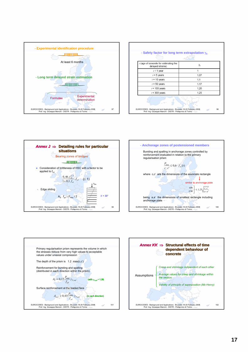
17
EUROCODES - Background and Applications - Brussels 18-20 February 2008 Prof. Ing. Giuseppe Mancini - DISTR - Politecnico di Torino
97
- Experimental identification procedure
At least 6 months
- Long term delayed strain estimation
Formulae Experimental determination
EUROCODES - Background and Applications - Brussels 18-20 February 2008 Prof. Ing. Giuseppe Mancini - DISTR - Politecnico di Torino
98
- Safety factor for long term extrapolation γlt
EUROCODES - Background and Applications - Brussels 18-20 February 2008 Prof. Ing. Giuseppe Mancini - DISTR - Politecnico di Torino
99
Annex Annex J J ⇒⇒ Detailing rules for particular Detailing rules for particular situationssituations
Consideration of brittleness of HSC with a factor to be applied to fcd
2 / 30, 46..
1 0,1.ck
cdck
ff
f+
Edge sliding
AS . fyd ≥ FRdu / 2
(≤ 1)
Bearing zones of bridges
ϑ = 30°
EUROCODES - Background and Applications - Brussels 18-20 February 2008 Prof. Ing. Giuseppe Mancini - DISTR - Politecnico di Torino
100
- Anchorage zones of postensioned members
Bursting and spalling in anchorage zones controlled by reinforcement evaluated in relation to the primary regularisation prism
)(6,0'
max tfcc
Pck⋅≤
⋅
where c,c‘ are the dimensions of the associate rectangle
'1, 25'
c ca a
⋅≤
⋅
similar to anchorage plate
c/ac’/a’
being a,a‘ the dimensions of smallest rectangle including anchorage plate
EUROCODES - Background and Applications - Brussels 18-20 February 2008 Prof. Ing. Giuseppe Mancini - DISTR - Politecnico di Torino
101
Primary regularisation prism represents the volume in which the stresses reduce from very high values to acceptable values under uniaxial compression
The depth of the prism is 1.2 max(c,c’)
Reinforcement for bursting and spalling(distributed in each direction within the prism)
Surface reinforcement at the loaded face
max,0,03surf P unf
yd
PA
fγ≥ (in each direction)
max,0,15S P unf
yd
PA
fγ= (with γP,unf = 1.20)
EUROCODES - Background and Applications - Brussels 18-20 February 2008 Prof. Ing. Giuseppe Mancini - DISTR - Politecnico di Torino
102
Annex Annex KK KK ⇒⇒ Structural effects Structural effects of time of time dependent behaviour dependent behaviour of of concrete concrete
Assumptions
Creep and shrinkage indipendent of each other
Average values for creep and shrinkage within the section
Validity of principle of superposition (Mc-Henry)
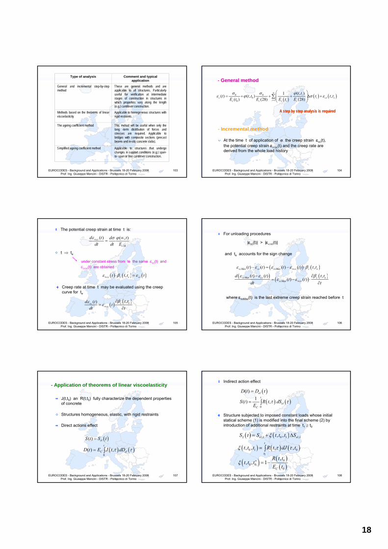
18
EUROCODES - Background and Applications - Brussels 18-20 February 2008 Prof. Ing. Giuseppe Mancini - DISTR - Politecnico di Torino
103
Type of analysis Comment and typical application
General and incremental step-by-step method
These are general methods and are applicable to all structures. Particularly useful for verification at intermediate stages of construction in structures in which properties vary along the length (e.g.) cantilever construction.
Methods based on the theorems of linear viscoelasticity
Applicable to homogeneous structures with rigid restraints.
The ageing coefficient method This mehod will be useful when only the long -term distribution of forces and stresses are required. Applicable to bridges with composite sections (precast beams and in-situ concrete slabs).
Simplified ageing coefficient method Applicable to structures that undergo changes in support conditions (e.g.) span-to- span or free cantilever construction.
EUROCODES - Background and Applications - Brussels 18-20 February 2008 Prof. Ing. Giuseppe Mancini - DISTR - Politecnico di Torino
104
- General method
( ) ( ) ( )0 00
10
( , )1( ) ( , ) ,( ) (28) (28)
ni
c i cs sic c c i c
t tt t t t t t
E t E E t Eσ σ ϕ
ε ϕ σ ε=
⎛ ⎞= + + + Δ +⎜ ⎟⎜ ⎟
⎝ ⎠∑
A step by step analysis is required
- Incremental method
At the time t of application of σ the creep strain εcc(t), the potential creep strain ε∝cc(t) and the creep rate are derived from the whole load history
EUROCODES - Background and Applications - Brussels 18-20 February 2008 Prof. Ing. Giuseppe Mancini - DISTR - Politecnico di Torino
105
The potential creep strain at time t is:
28
( ) ( , )cc
c
d t d tdt dt E
ε σ ϕ∞ ∞=
t ⇒ te
under constant stress from te the same εcc(t) and ε∝cc(t) are obtained
( ) ( ) ( ),cc c e cct t t tε β ε∞ ⋅ =
Creep rate at time t may be evaluated using the creep curve for te
( ) ( ),( ) c ecccc
t td tt
dt tβε
ε∞
∂=
∂
EUROCODES - Background and Applications - Brussels 18-20 February 2008 Prof. Ing. Giuseppe Mancini - DISTR - Politecnico di Torino
106
For unloading procedures
|εcc(t)| > |ε∝cc(t)|
and te accounts for the sign change
( ) ( )( ) ( ) ( ) ( ) ,ccMax cc ccMax cc c et t t t t tε ε ε ε β∞− = − ⋅
( ) ( ) ( )( ) ( ) ,( ) ( )ccMax cc c e
ccMax cc
d t t t tt t
dt tε ε β
ε ε∞
− ∂= − ⋅
∂
where εccMax(t) is the last extreme creep strain reached before t
EUROCODES - Background and Applications - Brussels 18-20 February 2008 Prof. Ing. Giuseppe Mancini - DISTR - Politecnico di Torino
107
- Application of theorems of linear viscoelasticity
J(t,t0) an R(t,t0) fully characterize the dependent properties of concrete
Structures homogeneous, elastic, with rigid restraints
Direct actions effect
( )( ) elS t S t=
( ) ( )0
( ) ,t
C elD t E J t dDτ τ= ∫
EUROCODES - Background and Applications - Brussels 18-20 February 2008 Prof. Ing. Giuseppe Mancini - DISTR - Politecnico di Torino
108
Indirect action effect
( )( ) = elD t D t
( ) ( )0
1( ) ,t
elC
S t R t dSE
τ τ= ∫
Structure subjected to imposed constant loads whose initial statical scheme (1) is modified into the final scheme (2) by introduction of additional restraints at time t1 ≥ t0
( ) ( )2 ,1 0 1 ,1, ,el elS t S t t t Sξ= + Δ
( ) ( ) ( )0 1 01
, , , ,t
tt t t R t dJ tξ τ τ= ∫
( ) ( )( )
00 0
0
,, , 1
C
R t tt t t
E tξ + = −
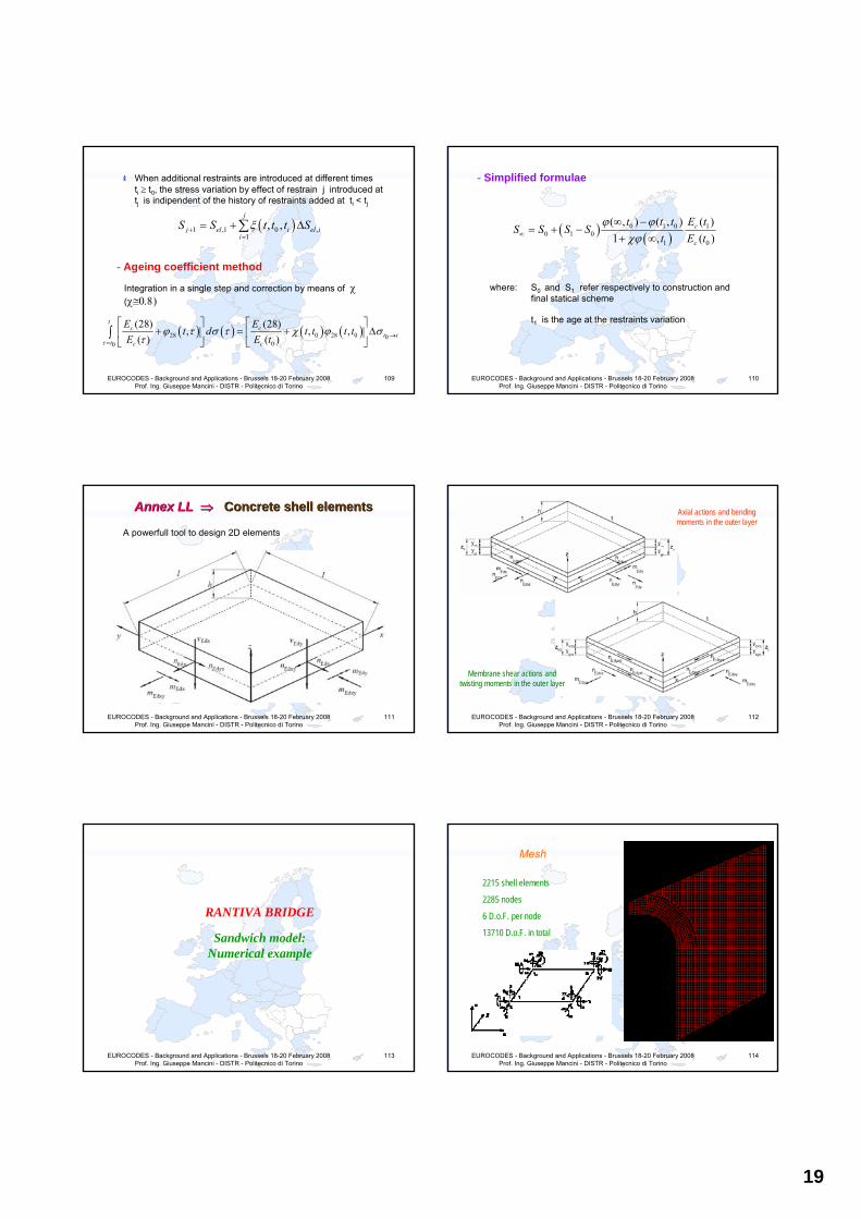
19
EUROCODES - Background and Applications - Brussels 18-20 February 2008 Prof. Ing. Giuseppe Mancini - DISTR - Politecnico di Torino
109
When additional restraints are introduced at different timesti ≥ t0, the stress variation by effect of restrain j introduced at tj is indipendent of the history of restraints added at ti < tj
( )1 ,1 0 ,1
, ,j
j el i el ii
S S t t t Sξ+=
= + Δ∑
- Ageing coefficient method
Integration in a single step and correction by means of χ(χ≅0.8)
( ) ( ) ( ) ( )28 0 28 0 000
(28) (28), , ,
( ) ( )
tc c
t tt c c
E Et d t t t t
E E tτϕ τ σ τ χ ϕ σ
τ →=
⎡ ⎤ ⎡ ⎤+ = + Δ⎢ ⎥ ⎢ ⎥
⎣ ⎦ ⎣ ⎦∫
EUROCODES - Background and Applications - Brussels 18-20 February 2008 Prof. Ing. Giuseppe Mancini - DISTR - Politecnico di Torino
110
- Simplified formulae
( ) ( )0 1 0 1
0 1 01 0
( , ) ( , ) ( )1 , ( )
c
c
t t t E tS S S S
t E tϕ ϕ
χϕ∞
∞ −= + −
+ ∞
where: S0 and S1 refer respectively to construction and final statical scheme
t1 is the age at the restraints variation
EUROCODES - Background and Applications - Brussels 18-20 February 2008 Prof. Ing. Giuseppe Mancini - DISTR - Politecnico di Torino
111
Annex Annex LL LL ⇒⇒ Concrete Concrete shell elements shell elements
A powerfull tool to design 2D elements
EUROCODES - Background and Applications - Brussels 18-20 February 2008 Prof. Ing. Giuseppe Mancini - DISTR - Politecnico di Torino
112
Axial actions and bending moments in the outer layer
Membrane shear actions and twisting moments in the outer layer
EUROCODES - Background and Applications - Brussels 18-20 February 2008 Prof. Ing. Giuseppe Mancini - DISTR - Politecnico di Torino
113
RANTIVA BRIDGE
Sandwich model:Numerical example
EUROCODES - Background and Applications - Brussels 18-20 February 2008 Prof. Ing. Giuseppe Mancini - DISTR - Politecnico di Torino
114
Mesh
2215 shell elements
2285 nodes
6 D.o.F. per node
13710 D.o.F. in total
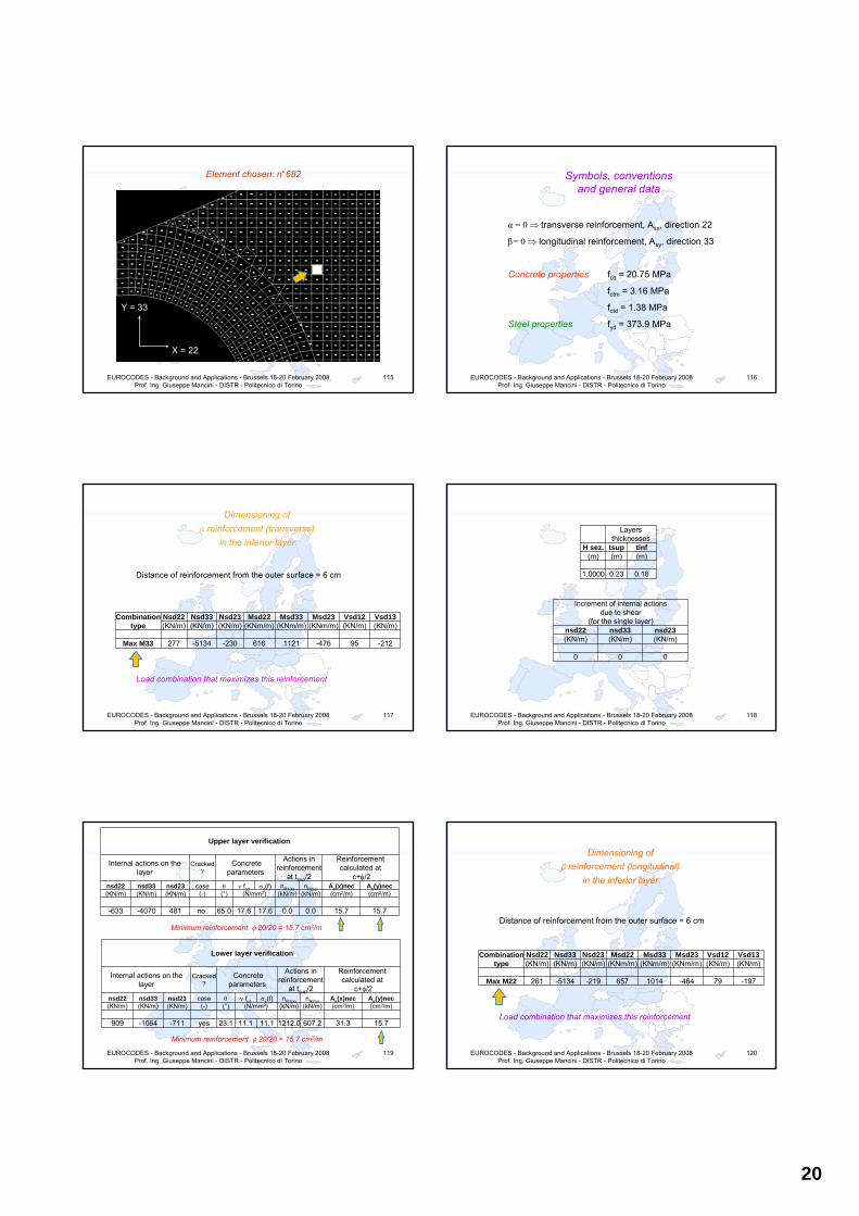
20
EUROCODES - Background and Applications - Brussels 18-20 February 2008 Prof. Ing. Giuseppe Mancini - DISTR - Politecnico di Torino
115
Element chosen: n°682
X = 22
Y = 33
EUROCODES - Background and Applications - Brussels 18-20 February 2008 Prof. Ing. Giuseppe Mancini - DISTR - Politecnico di Torino
116
Symbols, conventions and general data
α = 0 ⇒ transverse reinforcement, Asx, direction 22
β= 0 ⇒ longitudinal reinforcement, Asy, direction 33
Concrete properties fcd = 20.75 MPa
fctm = 3.16 MPa
fctd = 1.38 MPa
Steel properties fyd = 373.9 MPa
EUROCODES - Background and Applications - Brussels 18-20 February 2008 Prof. Ing. Giuseppe Mancini - DISTR - Politecnico di Torino
117
Dimensioning of α reinforcement (transverse)
in the inferior layer
Distance of reinforcement from the outer surface = 6 cm
Combinationtype
Nsd22 Nsd33 Nsd23 Msd22 Msd33 Msd23 Vsd12 Vsd13(KN/m) (KN/m) (KN/m) (KNm/m) (KNm/m) (KNm/m) (KN/m) (KN/m)
Max M33 277 -5134 -230 616 1121 -476 95 -212
Load combination that maximizes this reinforcement
EUROCODES - Background and Applications - Brussels 18-20 February 2008 Prof. Ing. Giuseppe Mancini - DISTR - Politecnico di Torino
118
Layers thicknesses
H sez. tsup tinf(m) (m) (m)
1.0000 0.23 0.18
Increment of internal actions due to shear
(for the single layer)nsd22 nsd33 nsd23(KN/m) (KN/m) (KN/m)
0 0 0
EUROCODES - Background and Applications - Brussels 18-20 February 2008 Prof. Ing. Giuseppe Mancini - DISTR - Politecnico di Torino
119
Upper layer verification
Internal actions on the layer
Cracked ?
Concrete parameters
Actions in reinforcement
at tsup/2
Reinforcement calculated at
c+φ/2nsd22 nsd33 nsd23 case θ ν fcd σc(f) nR1(x) nR2(y) As(x)nec As(y)nec(KN/m) (KN/m) (KN/m) (-) (°) (N/mm²) (kN/m) (kN/m) (cm2/m) (cm2/m)
-633 -4070 481 no. 65.0 17.6 17.6 0.0 0.0 15.7 15.7
Lower layer verification
Internal actions on the layer
Cracked ?
Concrete parameters
Actions in reinforcement
at tsup/2
Reinforcement calculated at
c+φ/2nsd22 nsd33 nsd23 case θ ν fcd σc(f) nR1(x) nR2(y) As(x)nec As(y)nec(KN/m) (KN/m) (KN/m) (-) (°) (N/mm²) (kN/m) (kN/m) (cm2/m) (cm2/m)
909 -1064 -711 yes 23.1 11.1 11.1 1212.0 607.2 31.3 15.7
Minimum reinforcement φ 20/20 = 15.7 cm2/m
Minimum reinforcement φ 20/20 = 15.7 cm2/m
EUROCODES - Background and Applications - Brussels 18-20 February 2008 Prof. Ing. Giuseppe Mancini - DISTR - Politecnico di Torino
120
Dimensioning of β reinforcement (longitudinal)
in the inferior layer
Distance of reinforcement from the outer surface = 6 cm
Combinationtype
Nsd22 Nsd33 Nsd23 Msd22 Msd33 Msd23 Vsd12 Vsd13(KN/m) (KN/m) (KN/m) (KNm/m) (KNm/m) (KNm/m) (KN/m) (KN/m)
Max M22 261 -5134 -219 657 1014 -464 79 -197
Load combination that maximizes this reinforcement

21
EUROCODES - Background and Applications - Brussels 18-20 February 2008 Prof. Ing. Giuseppe Mancini - DISTR - Politecnico di Torino
121
Layers thicknesses
H sez. tsup tinf(m) (m) (m)
1.0000 0.23 0.19
Increment of internal actions due to shear
(for the single layer)nsd22 nsd33 nsd23(KN/m) (KN/m) (KN/m)
0 0 0
EUROCODES - Background and Applications - Brussels 18-20 February 2008 Prof. Ing. Giuseppe Mancini - DISTR - Politecnico di Torino
122
Upper layer verification
Internal actions on the layer
Cracked ?
Concrete parameters
Actions in reinforcement
at tsup/2
Reinforcement calculated at
c+φ/2nsd22 nsd33 nsd23 case θ ν fcd σc(f) nR1(x) nR2(y) As(x)nec As(y)nec(KN/m) (KN/m) (KN/m) (-) (°) (N/mm²) (kN/m) (kN/m) (cm2/m) (cm2/m)
-695 -3904 474 no 45.0 17.6 17.6 0.0 0.0 15.7 15.7
Lower layer verification
Internal actions on the layer
Cracked ?
Concrete parameters
Actions in reinforcement
at tsup/2
Reinforcement calculated at
c+φ/2nsd22 nsd33 nsd23 case θ ν fcd σc(f) nR1(x) nR2(y) As(x)nec As(y)nec(KN/m) (KN/m) (KN/m) (-) (°) (N/mm²) (kN/m) (kN/m) (cm2/m) (cm2/m)
956 -1229 -693 yes 20.6 11.1 11.1 1216.7 611.5 31.3 15.7
Minimum reinforcement φ 20/20 = 15.7 cm2/m
Minimum reinforcement φ 20/20 = 15.7 cm2/m
EUROCODES - Background and Applications - Brussels 18-20 February 2008 Prof. Ing. Giuseppe Mancini - DISTR - Politecnico di Torino
123
Dimensioning of α reinforcement (transverse)
in the superior layer
Distance of reinforcement from the outer surface = 6 cm
Combinationtype
Nsd22 Nsd33 Nsd23 Msd22 Msd33 Msd23 Vsd12 Vsd13(KN/m) (KN/m) (KN/m) (KNm/m) (KNm/m) (KNm/m) (KN/m) (KN/m)
Max M22 261 -5134 -219 657 1014 -464 79 -197
Load combination that maximizes this reinforcement
EUROCODES - Background and Applications - Brussels 18-20 February 2008 Prof. Ing. Giuseppe Mancini - DISTR - Politecnico di Torino
124
Layers thicknesses
H sez. tsup tinf(m) (m) (m)
1.0000 0.23 0.19
Increment of internal actions due to shear
(for the single layer)nsd22 nsd33 nsd23(KN/m) (KN/m) (KN/m)
0 0 0
EUROCODES - Background and Applications - Brussels 18-20 February 2008 Prof. Ing. Giuseppe Mancini - DISTR - Politecnico di Torino
125
Upper layer verification
Internal actions on the layer
Cracked ?
Concrete parameters
Actions in reinforcement
at tsup/2
Reinforcement calculated at
c+φ/2nsd22 nsd33 nsd23 case θ ν fcd σc(f) nR1(x) nR2(y) As(x)nec As(y)nec(KN/m) (KN/m) (KN/m) (-) (°) (N/mm²) (kN/m) (kN/m) (cm2/m) (cm2/m)
-695 -3904 474 no 45.0 17.6 17.6 0.0 0.0 15.7 15.7
Lower layer verification
Internal actions on the layer
Cracked ?
Concrete parameters
Actions in reinforcement
at tsup/2
Reinforcement calculated at
c+φ/2nsd22 nsd33 nsd23 case θ ν fcd σc(f) nR1(x) nR2(y) As(x)nec As(y)nec(KN/m) (KN/m) (KN/m) (-) (°) (N/mm²) (kN/m) (kN/m) (cm2/m) (cm2/m)
956 -1229 -693 yes 20.6 11.1 11.1 1216.7 611.5 31.3 15.7
Minimum reinforcement φ 20/20 = 15.7 cm2/m
Minimum reinforcement φ 20/20 = 15.7 cm2/m
EUROCODES - Background and Applications - Brussels 18-20 February 2008 Prof. Ing. Giuseppe Mancini - DISTR - Politecnico di Torino
126
Dimensioning of β reinforcement (longitudinal)
in the superior layer
Distance of reinforcement from the outer surface = 6 cm
Combinationtype
Nsd22 Nsd33 Nsd23 Msd22 Msd33 Msd23 Vsd12 Vsd13(KN/m) (KN/m) (KN/m) (KNm/m) (KNm/m) (KNm/m) (KN/m) (KN/m)
Max M22 261 -5134 -219 657 1014 -464 79 -197
Load combination that maximizes this reinforcement
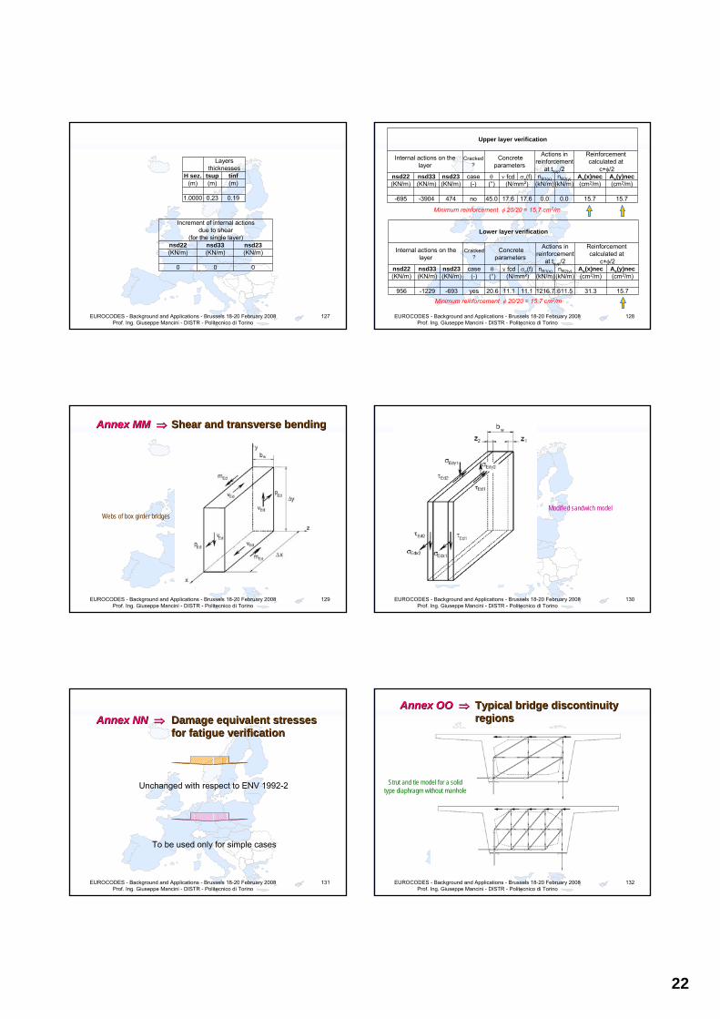
22
EUROCODES - Background and Applications - Brussels 18-20 February 2008 Prof. Ing. Giuseppe Mancini - DISTR - Politecnico di Torino
127
Layers thicknesses
H sez. tsup tinf(m) (m) (m)
1.0000 0.23 0.19
Increment of internal actions due to shear
(for the single layer)nsd22 nsd33 nsd23(KN/m) (KN/m) (KN/m)
0 0 0
EUROCODES - Background and Applications - Brussels 18-20 February 2008 Prof. Ing. Giuseppe Mancini - DISTR - Politecnico di Torino
128
Upper layer verification
Internal actions on the layer
Cracked ?
Concrete parameters
Actions in reinforcement
at tsup/2
Reinforcement calculated at
c+φ/2nsd22 nsd33 nsd23 case θ ν fcd σc(f) nR1(x) nR2(y) As(x)nec As(y)nec(KN/m) (KN/m) (KN/m) (-) (°) (N/mm²) (kN/m) (kN/m) (cm2/m) (cm2/m)
-695 -3904 474 no 45.0 17.6 17.6 0.0 0.0 15.7 15.7
Lower layer verification
Internal actions on the layer
Cracked ?
Concrete parameters
Actions in reinforcement
at tsup/2
Reinforcement calculated at
c+φ/2nsd22 nsd33 nsd23 case θ ν fcd σc(f) nR1(x) nR2(y) As(x)nec As(y)nec(KN/m) (KN/m) (KN/m) (-) (°) (N/mm²) (kN/m) (kN/m) (cm2/m) (cm2/m)
956 -1229 -693 yes 20.6 11.1 11.1 1216.7 611.5 31.3 15.7
Minimum reinforcement φ 20/20 = 15.7 cm2/m
Minimum reinforcement φ 20/20 = 15.7 cm2/m
EUROCODES - Background and Applications - Brussels 18-20 February 2008 Prof. Ing. Giuseppe Mancini - DISTR - Politecnico di Torino
129
Annex Annex MM MM ⇒⇒ Shear Shear and and transverse bending transverse bending
Webs of box girder bridges
EUROCODES - Background and Applications - Brussels 18-20 February 2008 Prof. Ing. Giuseppe Mancini - DISTR - Politecnico di Torino
130
Modified sandwich model
EUROCODES - Background and Applications - Brussels 18-20 February 2008 Prof. Ing. Giuseppe Mancini - DISTR - Politecnico di Torino
131
Annex Annex NN NN ⇒⇒ Damage equivalent stresses Damage equivalent stresses for fatigue verification for fatigue verification
Unchanged with respect to ENV 1992-2
To be used only for simple cases
EUROCODES - Background and Applications - Brussels 18-20 February 2008 Prof. Ing. Giuseppe Mancini - DISTR - Politecnico di Torino
132
Annex OO Annex OO ⇒⇒ Typical bridge discontinuity Typical bridge discontinuity regions regions
Strut and tie model for a solid type diaphragm without manhole
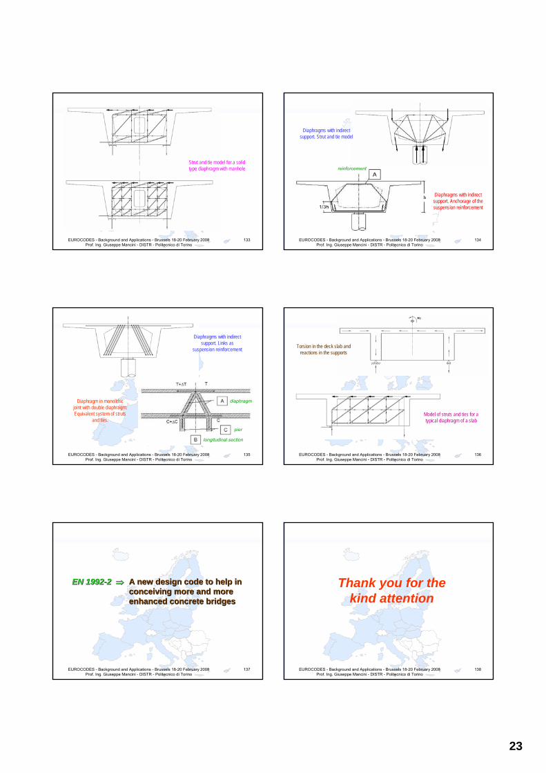
23
EUROCODES - Background and Applications - Brussels 18-20 February 2008 Prof. Ing. Giuseppe Mancini - DISTR - Politecnico di Torino
133
Strut and tie model for a solid type diaphragm with manhole
EUROCODES - Background and Applications - Brussels 18-20 February 2008 Prof. Ing. Giuseppe Mancini - DISTR - Politecnico di Torino
134
Diaphragms with indirect support. Strut and tie model
Diaphragms with indirect support. Anchorage of the suspension reinforcement
reinforcement
EUROCODES - Background and Applications - Brussels 18-20 February 2008 Prof. Ing. Giuseppe Mancini - DISTR - Politecnico di Torino
135
Diaphragms with indirect support. Links as
suspension reinforcement
diaphragm
pier
longitudinal section
Diaphragm in monolithic joint with double diaphragm:Equivalent system of struts
and ties.
EUROCODES - Background and Applications - Brussels 18-20 February 2008 Prof. Ing. Giuseppe Mancini - DISTR - Politecnico di Torino
136
Torsion in the deck slab and reactions in the supports
Model of struts and ties for a typical diaphragm of a slab
EUROCODES - Background and Applications - Brussels 18-20 February 2008 Prof. Ing. Giuseppe Mancini - DISTR - Politecnico di Torino
137
EN 1992EN 1992--22 ⇒⇒ A new design code to help in A new design code to help in conceiving more and more conceiving more and more enhanced concrete bridges enhanced concrete bridges
EUROCODES - Background and Applications - Brussels 18-20 February 2008 Prof. Ing. Giuseppe Mancini - DISTR - Politecnico di Torino
138
Thank you for thekind attention

EN1992-3
T. Jones Arup


Brussels, 18-20 February 2008 – Dissemination of information workshop 1
EUROCODESBackground and Applications EN 1992-3:2006
Eurocode 2 – Design of Concrete Structures –Part 3 : Liquid retaining and containment structures
Dr Tony JonesArup
Brussels, 18-20 February 2008 – Dissemination of information workshop 2
EUROCODESBackground and Applications EN 1992-3:2006
Introduction
Scope of Part 3
Changes to Part 1
Annexes
National Choices
Summary
Brussels, 18-20 February 2008 – Dissemination of information workshop 3
EUROCODESBackground and Applications EN 1992-3:2006
Introduction
Project Team– Convenor Prof. Andrew Beeby, UK.– Andrea Benedetti,Italy– Prof K van Breugel, Netherlands – Dr Dieter Pichler, Austria – Dr Karl-Heinz Reineck, Germany – M Grenier, France.
Task to Convert part 4 of the ENV to part 3 of EN1992.
Brussels, 18-20 February 2008 – Dissemination of information workshop 4
EUROCODESBackground and Applications EN 1992-3:2006
Why do we have part 3?
• Very few specific items
• Some manipulation of part 1 equations
• Some other rules that more correctly belong in part 1.
• Aim for next version to be included in part 1
Brussels, 18-20 February 2008 – Dissemination of information workshop 5
EUROCODESBackground and Applications EN 1992-3:2006
Scope of EN1992-3
• Additional rules for …… the containment of liquids or granular solids
• Only for those parts that directly support the stored materials
• Stored materials at -40°C to +200°C• “clauses covering liquid tightness may also be
relevant to other types of structure”
Brussels, 18-20 February 2008 – Dissemination of information workshop 6
EUROCODESBackground and Applications EN 1992-3:2006
Excludes
• Storage of materials at very high or low temperatures.
• Storage of materials leakage of which would constitute a major health risk.
• Pressurised vessels• Floating structures• Large dams• Gas tightness

Brussels, 18-20 February 2008 – Dissemination of information workshop 7
EUROCODESBackground and Applications EN 1992-3:2006
Changes to Part 1
• Background to why changes to part 1 are required
• Some background to their basis.
Brussels, 18-20 February 2008 – Dissemination of information workshop 8
EUROCODESBackground and Applications EN 1992-3:2006
Basic Design Variables
Special design situations
• Operating conditions• Explosions• Temperature of Stored materials• Testing
• Reference to EN1991-4 for Actions
Brussels, 18-20 February 2008 – Dissemination of information workshop 9
EUROCODESBackground and Applications EN 1992-3:2006
Materials
Concrete
• Effect of temperature on Material Properties (including creep) – Annex K
• Thermal Coefficient of Expansion – warning on variability.
Reinforcement
• Reference to EN1992-1-2 for temperatures >100°C
Brussels, 18-20 February 2008 – Dissemination of information workshop 10
EUROCODESBackground and Applications EN 1992-3:2006
Durability
Abrasion due to:Mechanical AttackPhysical AttackChemical Attack
Brussels, 18-20 February 2008 – Dissemination of information workshop 11
EUROCODESBackground and Applications EN 1992-3:2006
Analysis
• Consideration of temperature effects (gradients)
• Consideration of internal pressures– Solids at the surface– Liquids at the centre line
P
t Di
T/2T=P(Di+t)
Brussels, 18-20 February 2008 – Dissemination of information workshop 12
EUROCODESBackground and Applications EN 1992-3:2006
Ultimate Limit State
Shear under tension – Cot θ conservatively limited to 1.0
Note EN1992-1 limit of Cot θ for tension flanges = 1.25 – could have been a general rule
45°

Brussels, 18-20 February 2008 – Dissemination of information workshop 13
EUROCODESBackground and Applications EN 1992-3:2006
Design for dust explosion
Basic guidance given in EN 1991-4 and EN 1991-1-7
But TG thought that more helpful information should be provided:
• Venting and protection of surroundings• Actions considered acidental• Combination with other actions (part filled
bins)• Need for specialist assistance
Brussels, 18-20 February 2008 – Dissemination of information workshop 14
EUROCODESBackground and Applications EN 1992-3:2006
Serviceability
Brussels, 18-20 February 2008 – Dissemination of information workshop 15
EUROCODESBackground and Applications EN 1992-3:2006
Tightness Class 1 – Through Cracking
– Cracks may be expected to heal when range of strain under service conditions is less than 150 x 10-6
EN 1992-3
Original Diagram from Walraven
Brussels, 18-20 February 2008 – Dissemination of information workshop 16
EUROCODESBackground and Applications EN 1992-3:2006
Tightness Class 2
Minimum depth of compression zone (or section that remains in compression lesser of 50mm or 0.2h under quasi permanent loads
Brussels, 18-20 February 2008 – Dissemination of information workshop 17
EUROCODESBackground and Applications EN 1992-3:2006
Control of cracking without direct calculation
Revised figures for maximum bar spacing/bar stress given – These are as Part 1 except for Tension rather than Flexure
[Note: This also means the bar diameter
modification (exp 7.7N) is modified slightly]
Brussels, 18-20 February 2008 – Dissemination of information workshop 18
EUROCODESBackground and Applications EN 1992-3:2006
Calculation of crack width – refer to Annexes L and M
Minimising cracking due to restraint• Limit temperature rise• Reduce restraints• Use concrete with low thermal expansion• Use concrete with high tensile strain capacity• Apply prestress.

Brussels, 18-20 February 2008 – Dissemination of information workshop 19
EUROCODESBackground and Applications EN 1992-3:2006
Detailing
Guidance on:• Postensioning of circular tanks• Minimum wall thicknesses in prestressed
tanks• Temperature effects on unbonded tendons• Opening moments in the corners of tanks• Provision of movement joints.
Brussels, 18-20 February 2008 – Dissemination of information workshop 20
EUROCODESBackground and Applications EN 1992-3:2006
Annexes (all informative)
Annex K – Effect of temperature on the properties of concrete
Annex L – Calculation of strians and stresses in concrete sections subjected to restrained imposed deformations
Annex M – Calculation of crack widths due to restraint of imposed deformations
Annex N – Provision of movement joints
Brussels, 18-20 February 2008 – Dissemination of information workshop 21
EUROCODESBackground and Applications EN 1992-3:2006
Annex K – Effect of temperature in the properties of concrete.
• Material enhancements given for sub zero temperatures – not always conservative to ignore.
• For elevated temperatures reference to fire part, to avoid duplication.
• Methods presented to calculate increased creep (and transitional thermal strain) and reduced elastic modulus.
Brussels, 18-20 February 2008 – Dissemination of information workshop 22
EUROCODESBackground and Applications EN 1992-3:2006
Annex L – Calculation of the strains and stresses in concrete sections subjected to restrained imposed deformations
Actual strain εaz= (1-Rax)εiav
Stress in concrete σz = Ec,eff (εiav- εaz)
Brussels, 18-20 February 2008 – Dissemination of information workshop 23
EUROCODESBackground and Applications EN 1992-3:2006
Restraint Factor
Brussels, 18-20 February 2008 – Dissemination of information workshop 24
EUROCODESBackground and Applications EN 1992-3:2006
Annex M – Calculation of crack widths due to restraint of imposed deformations
Two case considered:

Brussels, 18-20 February 2008 – Dissemination of information workshop 25
EUROCODESBackground and Applications EN 1992-3:2006
End RestraintP P
Tension in steel = S
Tension in concrete = C
Tensile strength of concrete
At any point along the element force = P = C+S
Forc
e
Brussels, 18-20 February 2008 – Dissemination of information workshop 26
EUROCODESBackground and Applications EN 1992-3:2006
End RestraintP P
Tension in steel = S
Tension in concrete = C
Tensile strength of concrete
At any point along the element force = P = C+S
Forc
e
Bond zone
Brussels, 18-20 February 2008 – Dissemination of information workshop 27
EUROCODESBackground and Applications EN 1992-3:2006
End RestraintP P
Tension in steel = S
Tension in concrete = C Tensile strength of concrete
At any point along the element force = P = C+S
Forc
e
Brussels, 18-20 February 2008 – Dissemination of information workshop 28
EUROCODESBackground and Applications EN 1992-3:2006
εsm-εcm=0,5αekckfct,eff(1+1/(αeρ))/Es
Brussels, 18-20 February 2008 – Dissemination of information workshop 29
EUROCODESBackground and Applications EN 1992-3:2006
Edge Restraint
Zone 2
Zone 1
Zone 1 end restraintZone 2 edge restraint
Brussels, 18-20 February 2008 – Dissemination of information workshop 30
EUROCODESBackground and Applications EN 1992-3:2006
Edge Restraint
From Bamforth
εsm - εcm = Rax εfree

Brussels, 18-20 February 2008 – Dissemination of information workshop 31
EUROCODESBackground and Applications EN 1992-3:2006
Annex N – Provision of Movement Joints
Brussels, 18-20 February 2008 – Dissemination of information workshop 32
EUROCODESBackground and Applications EN 1992-3:2006
National Choices
• Definition of wk1 (crack width limit for tightness class 1 structures)
• Xmin depth of section to remain in compression for tightness class 2 structures
• κ maximum duct size related to wall thikness• t1 and t2 minimum wall thicknesses for class 0
and class 1 or 2 structures respectively.
Brussels, 18-20 February 2008 – Dissemination of information workshop 33
EUROCODESBackground and Applications EN 1992-3:2006
Summary
• Relatively short document• Most of what is in the main code could be
handled in Part 1• There is useful information in the Annexes
which are all informative to allow local interpretation as appropriate.
Related Documents