EMV/EMC · 163 EMV EMC 6

Welcome message from author
This document is posted to help you gain knowledge. Please leave a comment to let me know what you think about it! Share it to your friends and learn new things together.
Transcript
EMV/EMC · 163
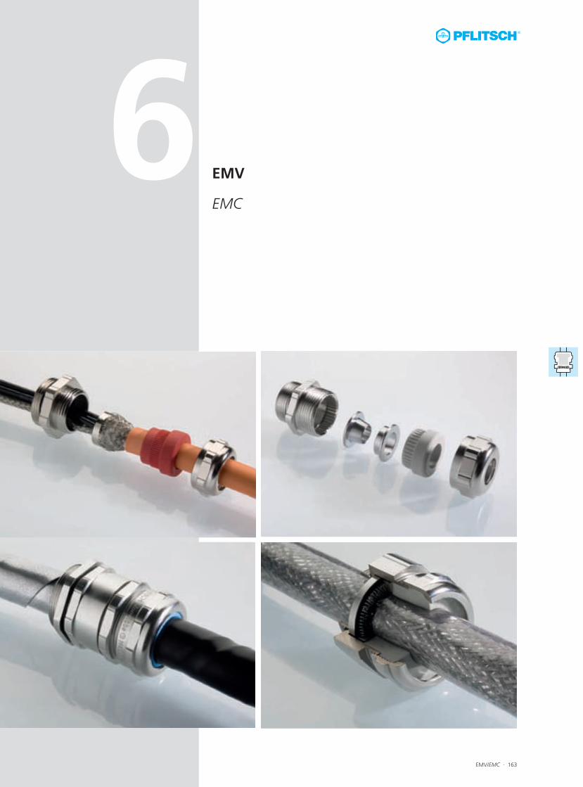
EMV
EMC
6
164 · EMV/EMC
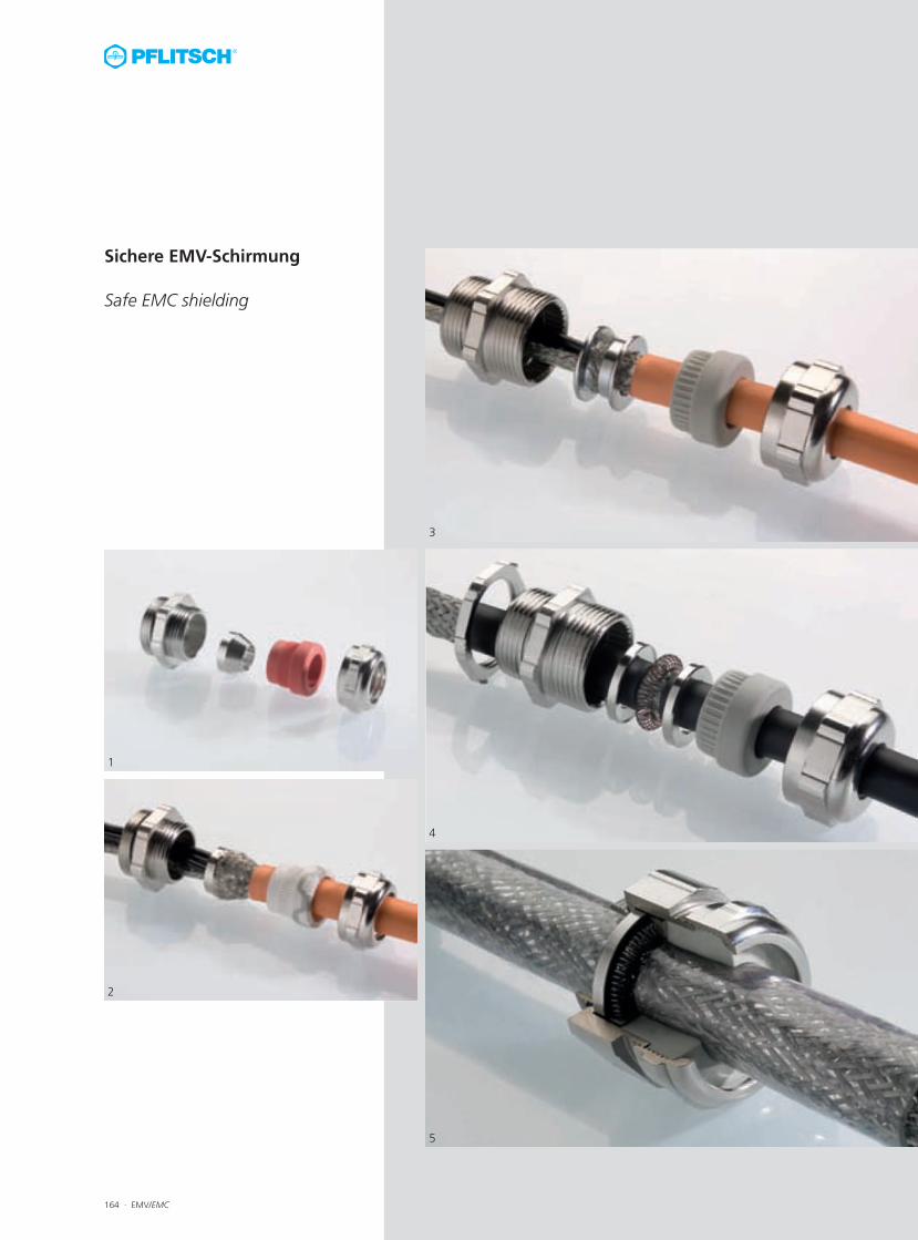
Sichere EMV-Schirmung
Safe EMC shielding
1
2
3
4
5
EMV/EMC · 165
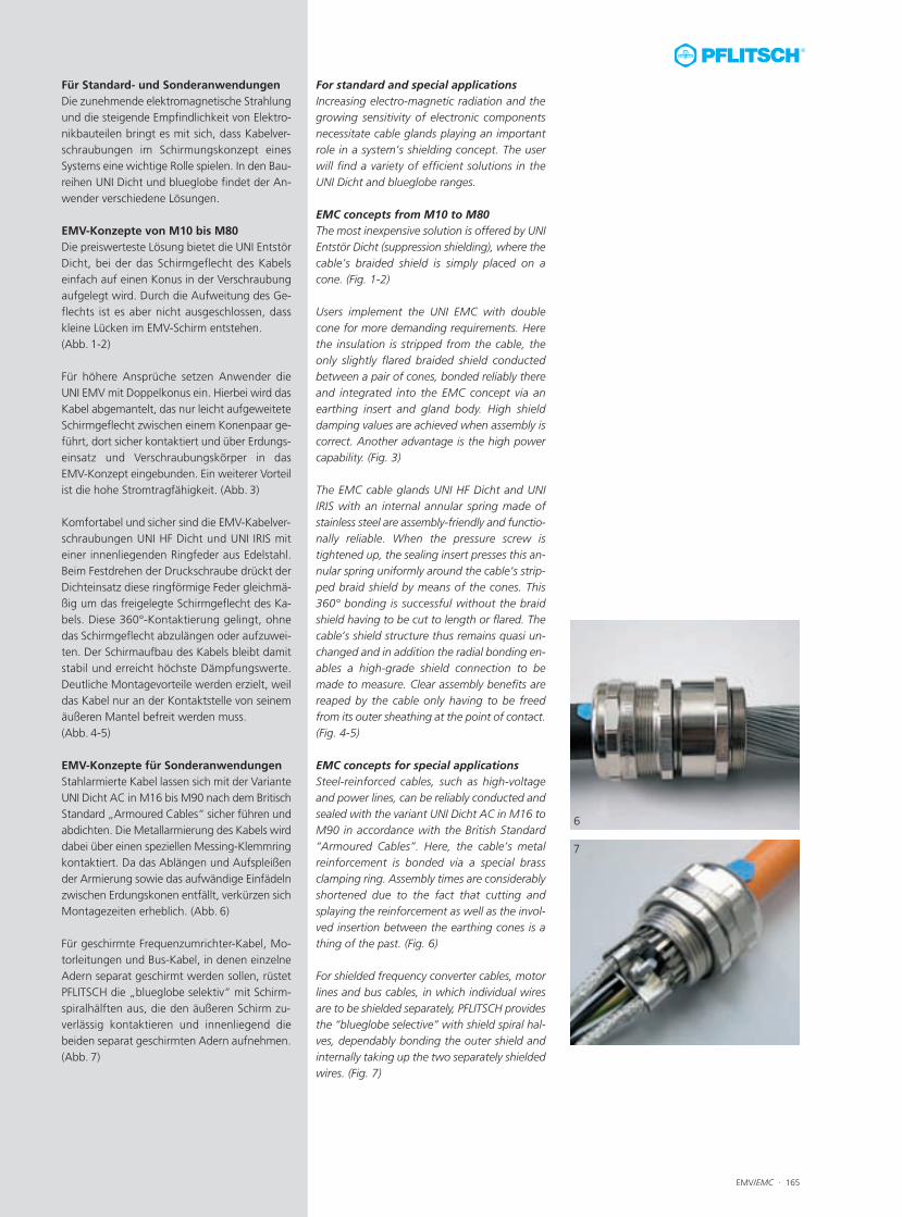
For standard and special applicationsIncreasing electro-magnetic radiation and thegrowing sensitivity of electronic componentsnecessitate cable glands playing an importantrole in a system’s shielding concept. The userwill find a variety of efficient solutions in theUNI Dicht and blueglobe ranges.
EMC concepts from M10 to M80The most inexpensive solution is offered by UNIEntstör Dicht (suppression shielding), where thecable’s braided shield is simply placed on acone. (Fig. 1-2)
Users implement the UNI EMC with doublecone for more demanding requirements. Herethe insulation is stripped from the cable, theonly slightly flared braided shield conductedbetween a pair of cones, bonded reliably thereand integrated into the EMC concept via anearthing insert and gland body. High shielddamping values are achieved when assembly iscorrect. Another advantage is the high powercapability. (Fig. 3)
The EMC cable glands UNI HF Dicht and UNIIRIS with an internal annular spring made ofstainless steel are assembly-friendly and functio-nally reliable. When the pressure screw istightened up, the sealing insert presses this an-nular spring uniformly around the cable’s strip-ped braid shield by means of the cones. This360° bonding is successful without the braidshield having to be cut to length or flared. Thecable’s shield structure thus remains quasi un-changed and in addition the radial bonding en-ables a high-grade shield connection to bemade to measure. Clear assembly benefits arereaped by the cable only having to be freedfrom its outer sheathing at the point of contact.(Fig. 4-5)
EMC concepts for special applicationsSteel-reinforced cables, such as high-voltageand power lines, can be reliably conducted andsealed with the variant UNI Dicht AC in M16 toM90 in accordance with the British Standard“Armoured Cables”. Here, the cable’s metalreinforcement is bonded via a special brassclamping ring. Assembly times are considerablyshortened due to the fact that cutting andsplaying the reinforcement as well as the invol-ved insertion between the earthing cones is athing of the past. (Fig. 6)
For shielded frequency converter cables, motorlines and bus cables, in which individual wiresare to be shielded separately, PFLITSCH providesthe “blueglobe selective” with shield spiral hal-ves, dependably bonding the outer shield andinternally taking up the two separately shieldedwires. (Fig. 7)
Für Standard- und SonderanwendungenDie zunehmende elektromagnetische Strahlungund die steigende Empfindlichkeit von Elektro-nikbauteilen bringt es mit sich, dass Kabelver-schraubungen im Schirmungskonzept einesSystems eine wichtige Rolle spielen. In den Bau-reihen UNI Dicht und blueglobe findet der An-wender verschiedene Lösungen.
EMV-Konzepte von M10 bis M80 Die preiswerteste Lösung bietet die UNI EntstörDicht, bei der das Schirmgeflecht des Kabelseinfach auf einen Konus in der Verschraubungaufgelegt wird. Durch die Aufweitung des Ge-flechts ist es aber nicht ausgeschlossen, dasskleine Lücken im EMV-Schirm entstehen.(Abb. 1-2)
Für höhere Ansprüche setzen Anwender dieUNI EMV mit Doppelkonus ein. Hierbei wird dasKabel abgemantelt, das nur leicht aufgeweiteteSchirmgeflecht zwischen einem Konenpaar ge-führt, dort sicher kontaktiert und über Erdungs-einsatz und Verschraubungskörper in dasEMV-Konzept eingebunden. Ein weiterer Vorteilist die hohe Stromtragfähigkeit. (Abb. 3)
Komfortabel und sicher sind die EMV-Kabelver-schraubungen UNI HF Dicht und UNI IRIS miteiner innenliegenden Ringfeder aus Edelstahl.Beim Festdrehen der Druckschraube drückt derDichteinsatz diese ringförmige Feder gleichmä-ßig um das freigelegte Schirmgeflecht des Ka-bels. Diese 360°-Kontaktierung gelingt, ohnedas Schirmgeflecht abzulängen oder aufzuwei-ten. Der Schirmaufbau des Kabels bleibt damitstabil und erreicht höchste Dämpfungswerte.Deutliche Montagevorteile werden erzielt, weildas Kabel nur an der Kontaktstelle von seinemäußeren Mantel befreit werden muss.(Abb. 4-5)
EMV-Konzepte für Sonderanwendungen Stahlarmierte Kabel lassen sich mit der VarianteUNI Dicht AC in M16 bis M90 nach dem BritischStandard „Armoured Cables“ sicher führen undabdichten. Die Metallarmierung des Kabels wirddabei über einen speziellen Messing-Klemmringkontaktiert. Da das Ablängen und Aufspleißender Armierung sowie das aufwändige Einfädelnzwischen Erdungskonen entfällt, verkürzen sichMontagezeiten erheblich. (Abb. 6)
Für geschirmte Frequenzumrichter-Kabel, Mo-torleitungen und Bus-Kabel, in denen einzelneAdern separat geschirmt werden sollen, rüstetPFLITSCH die „blueglobe selektiv“ mit Schirm-spiralhälften aus, die den äußeren Schirm zu-verlässig kontaktieren und innenliegend diebeiden separat geschirmten Adern aufnehmen. (Abb. 7)
6
7
166 · EMV/EMC
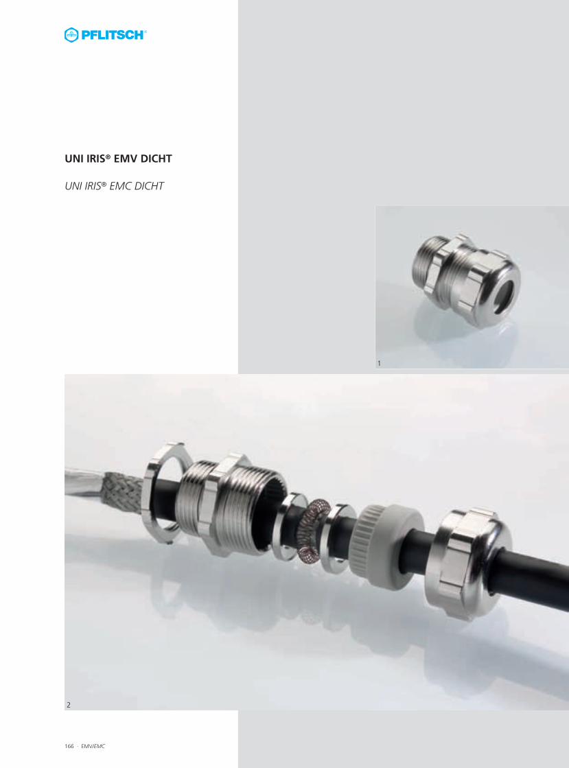
UNI IRIS® EMV DICHT
UNI IRIS® EMC DICHT
1
2
EMV/EMC · 167
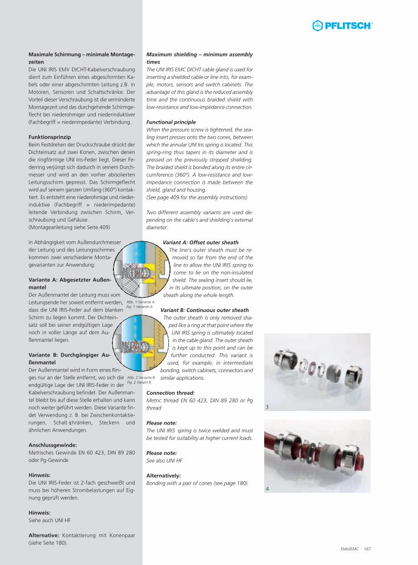
Maximum shielding – minimum assemblytimesThe UNI IRIS EMC DICHT cable gland is used forinserting a shielded cable or line into, for exam-ple, motors, sensors and switch cabinets. Theadvantage of this gland is the reduced assemblytime and the continuous braided shield withlow-resistance and low-impedance connection.
Functional principleWhen the pressure screw is tightened, the sea-ling insert presses onto the two cones, betweenwhich the annular UNI Iris spring is located. Thisspring-ring thus tapers in its diameter and ispressed on the previously stripped shielding.The braided shield is bonded along its entire cir-cumference (360°). A low-resistance and low-impedance connection is made between theshield, gland and housing.(See page 409 for the assembly instructions)
Two different assembly variants are used de-pending on the cable’s and shielding’s externaldiameter:
Variant A: Offset outer sheathThe line’s outer sheath must be re-moved so far from the end of theline to allow the UNI IRIS spring tocome to lie on the non-insulatedshield. The sealing insert should lie,
in its ultimate position, on the outersheath along the whole length.
Variant B: Continuous outer sheathThe outer sheath is only removed sha-ped like a ring at that point where theUNI IRIS spring is ultimately locatedin the cable gland. The outer sheathis kept up to this point and can befurther conducted. This variant is
used, for example, in intermediatebonding, switch cabinets, connectors andsimilar applications.
Connection thread:Metric thread EN 60 423, DIN 89 280 or Pgthread
Please note:The UNI IRIS� spring is twice welded and mustbe tested for suitability at higher current loads.
Please note:See also UNI HF
Alternatively:Bonding with a pair of cones (see page 180).
Maximale Schirmung – minimale Montage-zeitenDie UNI IRIS EMV DICHT-Kabelverschraubungdient zum Einführen eines abgeschirmten Ka-bels oder einer abgeschirmten Leitung z.B. inMotoren, Sensoren und Schaltschränke. DerVorteil dieser Verschraubung ist die verminderteMontagezeit und das durchgehende Schirmge-flecht bei niederohmiger und niederinduktiver(Fachbegriff = niederimpedante) Verbindung.
FunktionsprinzipBeim Festdrehen der Druckschraube drückt derDichteinsatz auf zwei Konen, zwischen denendie ringförmige UNI Iris-Feder liegt. Dieser Fe-derring verjüngt sich dadurch in seinem Durch-messer und wird an den vorher abisoliertenLeitungsschirm gepresst. Das Schirmgeflechtwird auf seinem ganzen Umfang (360°) kontak-tiert. Es entsteht eine niederohmige und nieder-induktive (Fachbegriff = niederimpedante)leitende Verbindung zwischen Schirm, Ver-schraubung und Gehäuse.(Montageanleitung siehe Seite 409)
In Abhängigkeit vom Außendurchmesserder Leitung und des Leitungsschirmeskommen zwei verschiedene Monta-gevarianten zur Anwendung:
Variante A: Abgesetzter Außen-mantelDer Außenmantel der Leitung muss vomLeitungsende her soweit entfernt werden,dass die UNI IRIS-Feder auf dem blankenSchirm zu liegen kommt. Der Dichtein-satz soll bei seiner endgültigen Lagenoch in voller Länge auf dem Au-ßenmantel liegen.
Variante B: Durchgängiger Au-ßenmantelDer Außenmantel wird in Form eines Rin-ges nur an der Stelle entfernt, wo sich dieendgültige Lage der UNI IRIS-Feder in derKabelverschraubung befindet. Der Außenman-tel bleibt bis auf diese Stelle erhalten und kannnoch weiter geführt werden. Diese Variante fin-det Verwendung z. B. bei Zwischenkontaktie-rungen, Schalt schränken, Steckern undähnlichen Anwendungen.
Anschlussgewinde:Metrisches Gewinde EN 60 423, DIN 89 280oder Pg-Gewinde
Hinweis: Die UNI IRIS-Feder ist 2-fach geschweißt undmuss bei höheren Strombelastungen auf Eig-nung geprüft werden.
Hinweis: Siehe auch UNI HF
Alternative: Kontaktierung mit Konenpaar(siehe Seite 180).
3
4
Abb. 1 Variante AFig. 1 Variante A
Abb. 2 Variante BFig. 2 Variant B
168 · EMV/EMC
-
-
Abb. 3 – Variante A mit abgesetztem AußenmantelFig. 3 – Variant A with stripped outer sheath
Abb. 4 – Variante B mit durchgängigem AußenmantelFig. 4 – Variant B continuous outer sheath
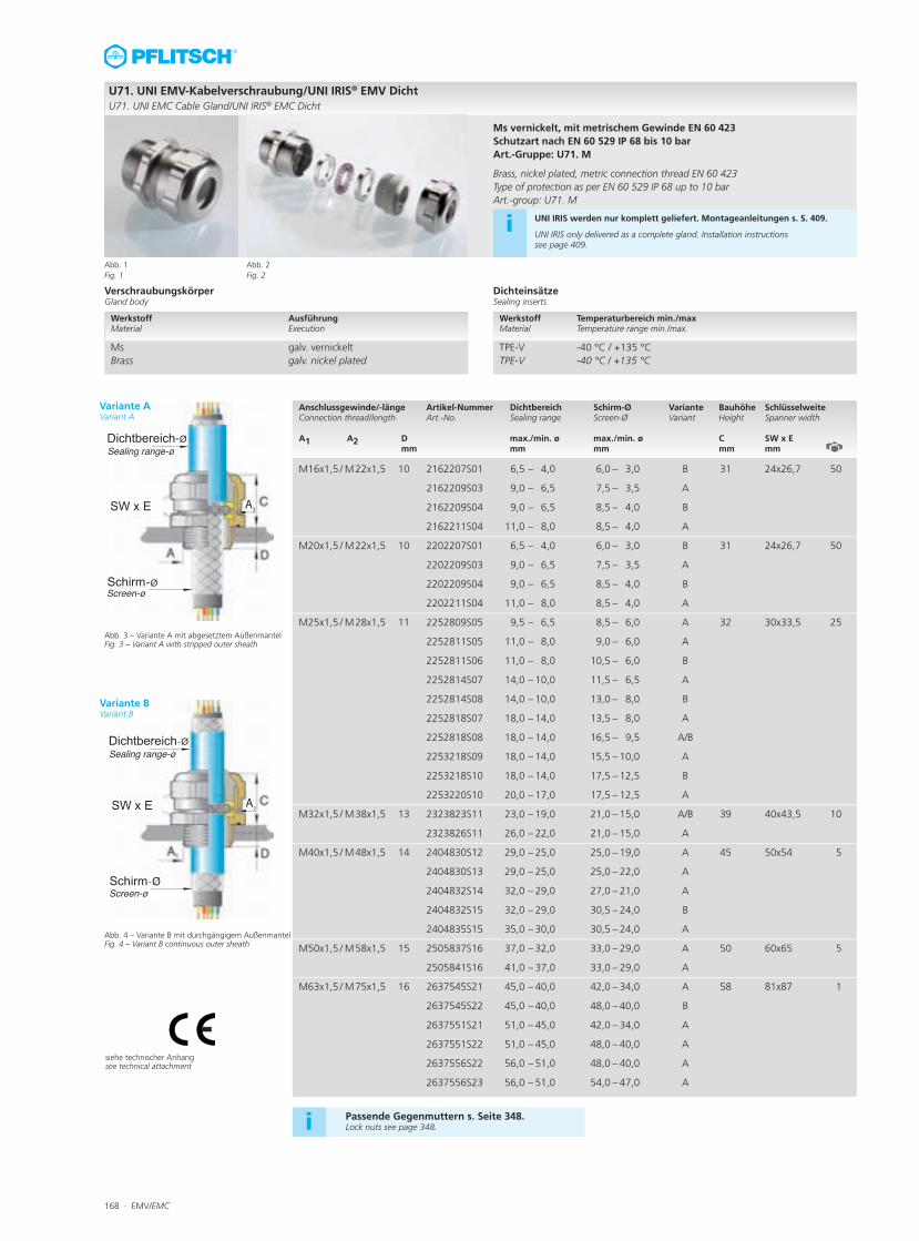
U71. UNI EMV-Kabelverschraubung/UNI IRIS® EMV DichtU71. UNI EMC Cable Gland/UNI IRIS® EMC Dicht
Ms vernickelt, mit metrischem Gewinde EN 60 423Schutzart nach EN 60 529 IP 68 bis 10 bar Art.-Gruppe: U71. M
Brass, nickel plated, metric connection thread EN 60 423Type of protection as per EN 60 529 IP 68 up to 10 bar Art.-group: U71. M
VerschraubungskörperGland body
DichteinsätzeSealing inserts
Anschlussgewinde/-länge Artikel-Nummer Dichtbereich Schirm-Ø Variante Bauhöhe SchlüsselweiteConnection thread/length Art.-No. Sealing range Screen-Ø Variant Height Spanner width A1 A2 D max./min. ø max./min. ø C SW x E
mm mm mm mm mm
Werkstoff Temperaturbereich min./max Material Temperature range min./max.
TPE-V -40 °C / +135 °CTPE-V -40 °C / +135 °C
M16x1,5 / M22x1,5 10 2162207S01 6,5 – 4,0 6,0 – 3,0 B 31 24x26,7 50
2162209S03 9,0 – 6,5 7,5 – 3,5 A
2162209S04 9,0 – 6,5 8,5 – 4,0 B
2162211S04 11,0 – 8,0 8,5 – 4,0 A
M20x1,5 / M22x1,5 10 2202207S01 6,5 – 4,0 6,0 – 3,0 B 31 24x26,7 50
2202209S03 9,0 – 6,5 7,5 – 3,5 A
2202209S04 9,0 – 6,5 8,5 – 4,0 B
2202211S04 11,0 – 8,0 8,5 – 4,0 A
M25x1,5 / M28x1,5 11 2252809S05 9,5 – 6,5 8,5 – 6,0 A 32 30x33,5 25
2252811S05 11,0 – 8,0 9,0 – 6,0 A
2252811S06 11,0 – 8,0 10,5 – 6,0 B
2252814S07 14,0 – 10,0 11,5 – 6,5 A
2252814S08 14,0 – 10,0 13,0 – 8,0 B
2252818S07 18,0 – 14,0 13,5 – 8,0 A
2252818S08 18,0 – 14,0 16,5 – 9,5 A/B
2253218S09 18,0 – 14,0 15,5 – 10,0 A
2253218S10 18,0 – 14,0 17,5 – 12,5 B
2253220S10 20,0 – 17,0 17,5 – 12,5 A
M32x1,5 / M38x1,5 13 2323823S11 23,0 – 19,0 21,0 – 15,0 A/B 39 40x43,5 10
2323826S11 26,0 – 22,0 21,0 – 15,0 A
M40x1,5 / M48x1,5 14 2404830S12 29,0 – 25,0 25,0 – 19,0 A 45 50x54 5
2404830S13 29,0 – 25,0 25,0 – 22,0 A
2404832S14 32,0 – 29,0 27,0 – 21,0 A
2404832S15 32,0 – 29,0 30,5 – 24,0 B
2404835S15 35,0 – 30,0 30,5 – 24,0 A
M50x1,5 / M58x1,5 15 2505837S16 37,0 – 32,0 33,0 – 29,0 A 50 60x65 5
2505841S16 41,0 – 37,0 33,0 – 29,0 A
M63x1,5 / M75x1,5 16 2637545S21 45,0 – 40,0 42,0 – 34,0 A 58 81x87 1
2637545S22 45,0 – 40,0 48,0 – 40,0 B
2637551S21 51,0 – 45,0 42,0 – 34,0 A
2637551S22 51,0 – 45,0 48,0 – 40,0 A
2637556S22 56,0 – 51,0 48,0 – 40,0 A
2637556S23 56,0 – 51,0 54,0 – 47,0 A
Werkstoff Ausführung Material Execution
Ms galv. vernickelt Brass galv. nickel plated
i UNI IRIS werden nur komplett geliefert. Montageanleitungen s. S. 409.
UNI IRIS only delivered as a complete gland. Installation instructions see page 409.
Abb. 1Fig. 1
Abb. 2Fig. 2
siehe technischer Anhangsee technical attachment
Passende Gegenmuttern s. Seite 348.Lock nuts see page 348.i
Variante AVariant A
Variante BVariant B
EMV/EMC · 169
-
-
Abb. 3 – Variante A mit abgesetztem AußenmantelFig. 3 – Variant A with stripped outer sheath
Abb. 4 – Variante B mit durchgängigem AußenmantelFig. 4 – Variant B continuous outer sheath
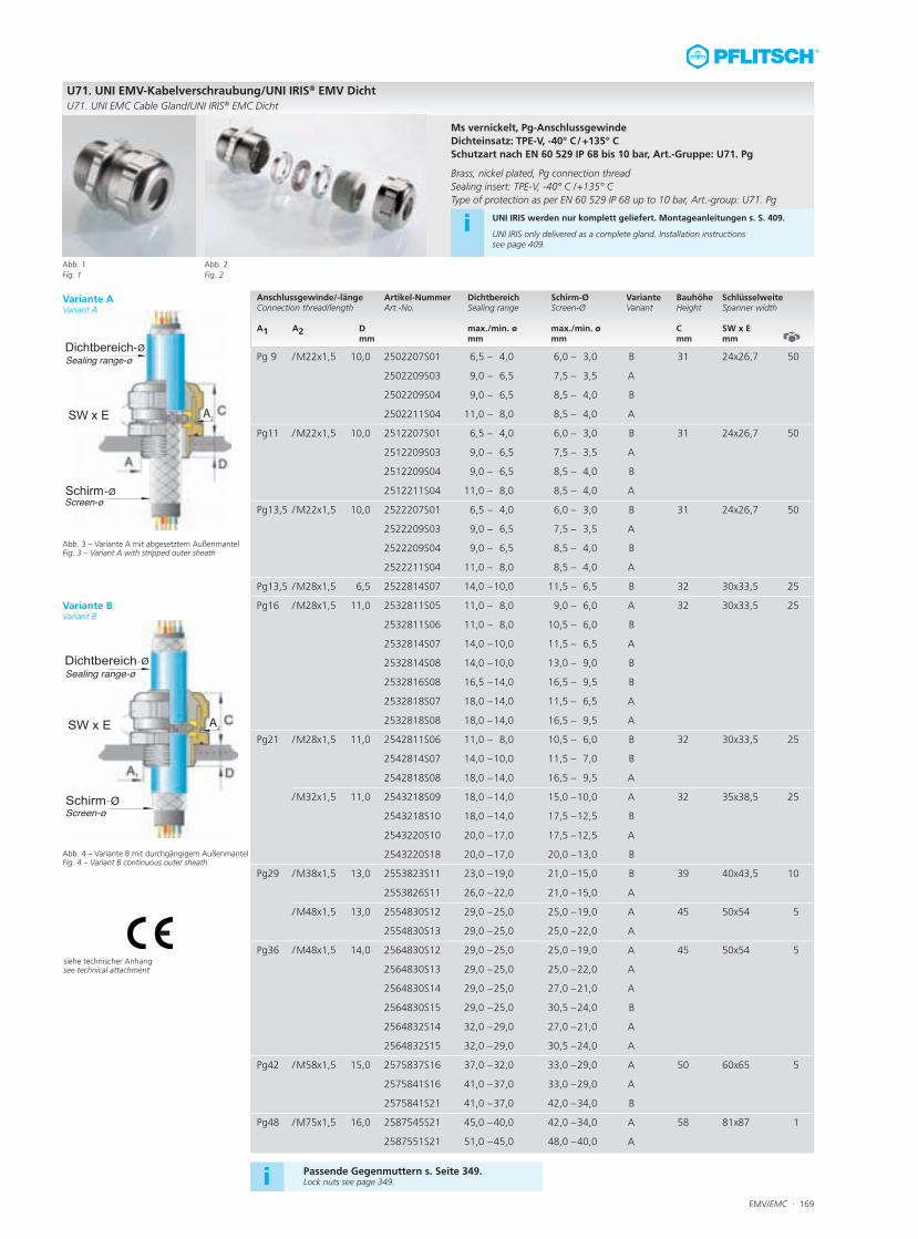
U71. UNI EMV-Kabelverschraubung/UNI IRIS® EMV DichtU71. UNI EMC Cable Gland/UNI IRIS® EMC Dicht
Anschlussgewinde/-länge Artikel-Nummer Dichtbereich Schirm-Ø Variante Bauhöhe SchlüsselweiteConnection thread/length Art.-No. Sealing range Screen-Ø Variant Height Spanner width A1 A2 D max./min. ø max./min. ø C SW x E
mm mm mm mm mm
Pg 9 /M22x1,5 10,0 2502207S01 6,5 – 4,0 6,0 – 3,0 B 31 24x26,7 50
2502209S03 9,0 – 6,5 7,5 – 3,5 A
2502209S04 9,0 – 6,5 8,5 – 4,0 B
2502211S04 11,0 – 8,0 8,5 – 4,0 A
Pg11 /M22x1,5 10,0 2512207S01 6,5 – 4,0 6,0 – 3,0 B 31 24x26,7 50
2512209S03 9,0 – 6,5 7,5 – 3,5 A
2512209S04 9,0 – 6,5 8,5 – 4,0 B
2512211S04 11,0 – 8,0 8,5 – 4,0 A
Pg13,5 /M22x1,5 10,0 2522207S01 6,5 – 4,0 6,0 – 3,0 B 31 24x26,7 50
2522209S03 9,0 – 6,5 7,5 – 3,5 A
2522209S04 9,0 – 6,5 8,5 – 4,0 B
2522211S04 11,0 – 8,0 8,5 – 4,0 A
Pg13,5 /M28x1,5 6,5 2522814S07 14,0 –10,0 11,5 – 6,5 B 32 30x33,5 25
Pg16 /M28x1,5 11,0 2532811S05 11,0 – 8,0 9,0 – 6,0 A 32 30x33,5 25
2532811S06 11,0 – 8,0 10,5 – 6,0 B
2532814S07 14,0 –10,0 11,5 – 6,5 A
2532814S08 14,0 –10,0 13,0 – 9,0 B
2532816S08 16,5 –14,0 16,5 – 9,5 B
2532818S07 18,0 –14,0 11,5 – 6,5 A
2532818S08 18,0 –14,0 16,5 – 9,5 A
Pg21 /M28x1,5 11,0 2542811S06 11,0 – 8,0 10,5 – 6,0 B 32 30x33,5 25
2542814S07 14,0 –10,0 11,5 – 7,0 B
2542818S08 18,0 –14,0 16,5 – 9,5 A
/M32x1,5 11,0 2543218S09 18,0 –14,0 15,0 –10,0 A 32 35x38,5 25
2543218S10 18,0 –14,0 17,5 –12,5 B
2543220S10 20,0 –17,0 17,5 –12,5 A
2543220S18 20,0 –17,0 20,0 –13,0 B
Pg29 /M38x1,5 13,0 2553823S11 23,0 –19,0 21,0 –15,0 B 39 40x43,5 10
2553826S11 26,0 –22,0 21,0 –15,0 A
/M48x1,5 13,0 2554830S12 29,0 –25,0 25,0 –19,0 A 45 50x54 5
2554830S13 29,0 –25,0 25,0 –22,0 A
Pg36 /M48x1,5 14,0 2564830S12 29,0 –25,0 25,0 –19,0 A 45 50x54 5
2564830S13 29,0 –25,0 25,0 –22,0 A
2564830S14 29,0 –25,0 27,0 –21,0 A
2564830S15 29,0 –25,0 30,5 –24,0 B
2564832S14 32,0 –29,0 27,0 –21,0 A
2564832S15 32,0 –29,0 30,5 –24,0 A
Pg42 /M58x1,5 15,0 2575837S16 37,0 –32,0 33,0 –29,0 A 50 60x65 5
2575841S16 41,0 –37,0 33,0 –29,0 A
2575841S21 41,0 –37,0 42,0 –34,0 B
Pg48 /M75x1,5 16,0 2587545S21 45,0 –40,0 42,0 –34,0 A 58 81x87 1
2587551S21 51,0 –45,0 48,0 –40,0 A
Abb. 1Fig. 1
Abb. 2Fig. 2
siehe technischer Anhangsee technical attachment
Passende Gegenmuttern s. Seite 349.Lock nuts see page 349.i
Ms vernickelt, Pg-Anschlussgewinde Dichteinsatz: TPE-V, -40° C/+135° C Schutzart nach EN 60 529 IP 68 bis 10 bar, Art.-Gruppe: U71. Pg
Brass, nickel plated, Pg connection threadSealing insert: TPE-V, -40° C /+135° C Type of protection as per EN 60 529 IP 68 up to 10 bar, Art.-group: U71. Pg
i UNI IRIS werden nur komplett geliefert. Montageanleitungen s. S. 409.
UNI IRIS only delivered as a complete gland. Installation instructions see page 409.
Variante AVariant A
Variante BVariant B
170 · EMV/EMC
-
-
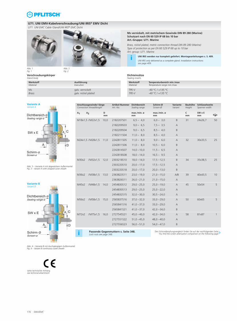
Abb. 3 – Variante A mit abgesetztem AußenmantelFig. 3 – Variant A with stripped outer sheath
Abb. 4 – Variante B mit durchgängigem AußenmantelFig. 4 – Variant B continuous outer sheath
U71. UNI EMV-Kabelverschraubung/UNI IRIS® EMV DichtU71. UNI EMC Cable Gland/UNI IRIS® EMC Dicht
Anschlussgewinde/-länge Artikel-Nummer Dichtbereich Schirm-Ø Variante Bauhöhe SchlüsselweiteConnection thread/length Art.-No. Sealing range Screen-Ø Variant Height Spanner width A1 A2 D max./min. ø max./min. ø C SW x E
mm mm mm mm mm
M18x1,5 /M22x1,5 10,0 2182207S01 6,5 – 4,0 6,0 – 3,0 B 31 24x26,7 50
2182209S03 9,0 – 6,5 7,5 – 3,5 A
2182209S04 9,0 – 6,5 8,5 – 4,0 B
2182211S04 11,0 – 8,0 8,5 – 4,0 A
M24x1,5 /M28x1,5 11,0 2242811S05 11,0 – 8,0 9,0 – 6,0 A 32 30x33,5 25
2242811S06 11,0 – 8,0 10,5 – 6,0 B
2242814S07 14,0 –10,0 11,5 – 6,5 A
2242818S08 18,0 –14,0 16,5 – 9,5 A
M30x2 /M32x1,5 12,0 2303218S10 18,0 –14,0 17,5 –12,5 B 34 35x38,5 25
2303220S10 20,0 –17,0 17,5 –12,5 A
2303220S18 20,0 –17,0 20,0 –13,0 B
M36x2 /M38x1,5 13,0 2363823S11 23,0 –19,0 21,0 –15,0 A/B 39 40x43,5 10
2363826S11 26,0 –21,0 21,0 –15,0 A
M45x2 /M48x1,5 14,0 2454830S12 29,0 –25,0 25,0 –19,0 A 45 50x54 5
2454830S13 29,0 –25,0 25,0 –22,0 A
2454832S15 32,0 –30,0 30,5 –24,0 A
M56x2 /M58x1,5 15,0 2565837S16 37,0 –32,0 33,0 –29,0 A 50 60x65 5
2565841S16 41,0 –37,0 33,0 –29,0 A
2565841S21 41,0 –37,0 42,0 –34,0 B
M72x2 /M75x1,5 16,0 2727545S21 45,0 –40,0 42,0 –34,0 A 58 81x87 1
2727551S22 51,0 –45,0 48,0 –40,0 A
2727556S23 56,0 –51,0 54,0 –47,0 B
Abb. 1Fig. 1
Abb. 2Fig. 2
siehe technischer Anhangsee technical attachment
Ms vernickelt, mit metrischem Gewinde DIN 89 280 (Marine)Schutzart nach EN 60 529 IP 68 bis 10 barArt.-Gruppe: U71. Marine
Brass, nickel plated, metric connection thread DIN 89 280 (Marine)Type of protection as per EN 60 529 IP 68 up to 10 barArt.-group: U71. Marine
i UNI IRIS werden nur komplett geliefert. Montageanleitungen s. S. 409.
UNI IRIS only delivered as a complete gland. Installation instructions see page 409.
VerschraubungskörperGland body
DichteinsätzeSealing inserts
Werkstoff Temperaturbereich min./max Material Temperature range min./max.
TPE-V -40 °C / +135 °CTPE-V -40 °C / +135 °C
Werkstoff Ausführung Material Execution
Ms galv. vernickelt Brass galv. nickel plated
Passende Gegenmuttern s. Seite 348.Lock nuts see page 348.i Den Schirmdämpfungsvergleich finden Sie auf der nachfolgenden Seite
You find the screen attenuation comparison on the following page
Variante AVariant A
Variante BVariant B
EMV/EMC · 171
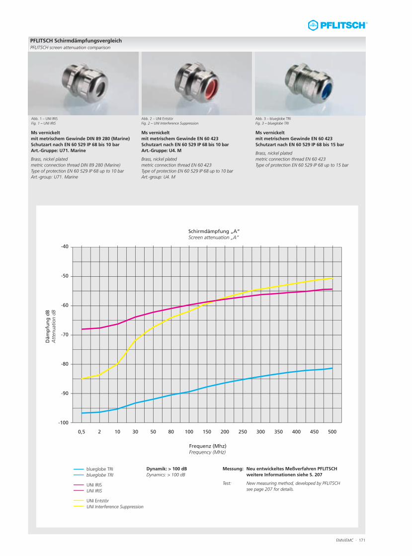
blueglobe TRIblueglobe TRI
UNI IRISUNI IRIS
UNI EntstörUNI Interference Suppression
Messung: Neu entwickeltes Meßverfahren PFLITSCHweitere Informationen siehe S. 207
Test: New measuring method, developed by PFLITSCHsee page 207 for details.
Dynamik: > 100 dBDynamics: > 100 dB
PFLITSCH SchirmdämpfungsvergleichPFLITSCH screen attenuation comparison
Abb. 1 – UNI IRISFig. 1 – UNI IRIS
Ms vernickeltmit metrischem Gewinde DIN 89 280 (Marine)Schutzart nach EN 60 529 IP 68 bis 10 barArt.-Gruppe: U71. Marine
Brass, nickel platedmetric connection thread DIN 89 280 (Marine)Type of protection EN 60 529 IP 68 up to 10 barArt.-group: U71. Marine
Abb. 3 – blueglobe TRIFig. 3 – blueglobe TRI
Ms vernickeltmit metrischem Gewinde EN 60 423Schutzart nach EN 60 529 IP 68 bis 15 bar
Brass, nickel platedmetric connection thread EN 60 423Type of protection EN 60 529 IP 68 up to 15 bar
Abb. 2 – UNI EntstörFig. 2 – UNI Interference Suppression
Ms vernickeltmit metrischem Gewinde EN 60 423Schutzart nach EN 60 529 IP 68 bis 10 barArt.-Gruppe: U4. M
Brass, nickel platedmetric connection thread EN 60 423Type of protection EN 60 529 IP 68 up to 10 barArt.-group: U4. M
172 · EMV/EMC
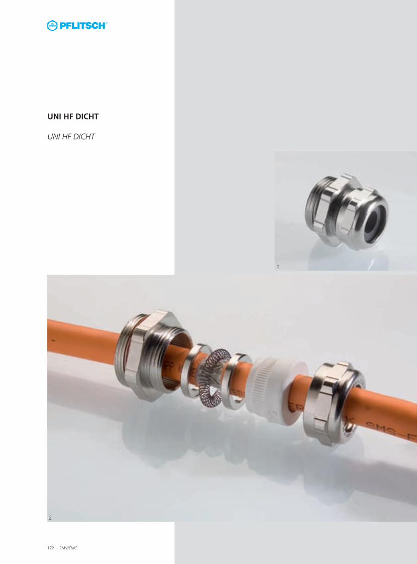
UNI HF DICHT
UNI HF DICHT
1
2
EMV/EMC · 173
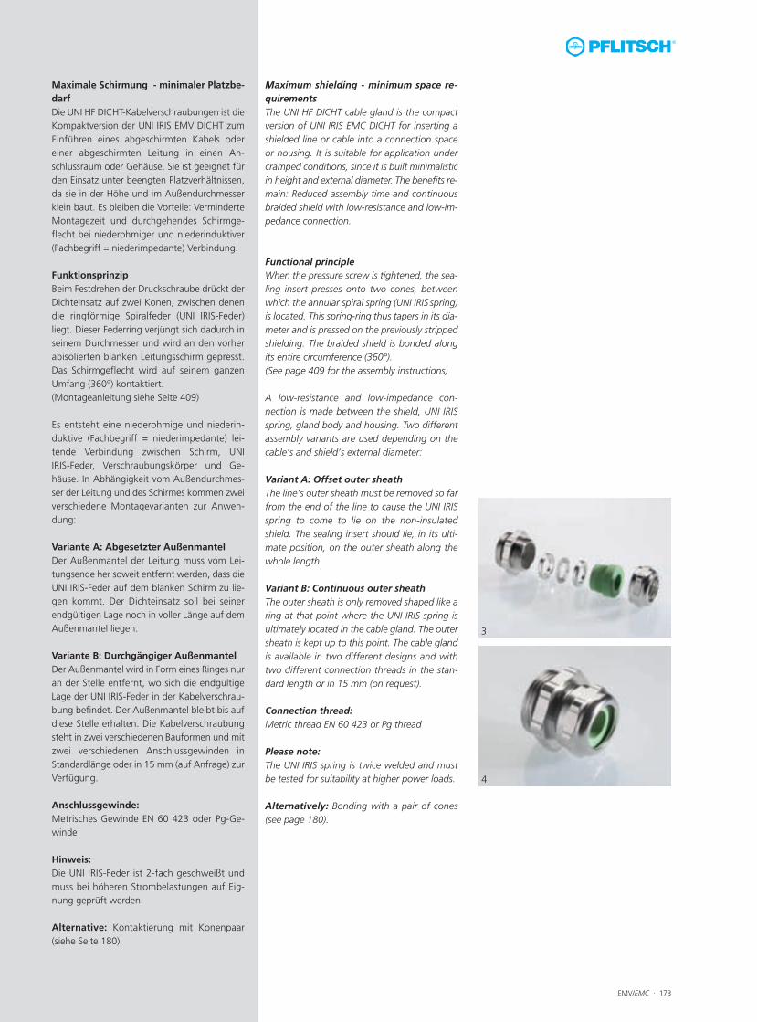
Maximum shielding - minimum space re-quirementsThe UNI HF DICHT cable gland is the compactversion of UNI IRIS EMC DICHT for inserting ashielded line or cable into a connection spaceor housing. It is suitable for application undercramped conditions, since it is built minimalisticin height and external diameter. The benefits re-main: Reduced assembly time and continuousbraided shield with low-resistance and low-im-pedance connection.
Functional principleWhen the pressure screw is tightened, the sea-ling insert presses onto two cones, betweenwhich the annular spiral spring (UNI IRIS spring)is located. This spring-ring thus tapers in its dia-meter and is pressed on the previously strippedshielding. The braided shield is bonded alongits entire circumference (360°). (See page 409 for the assembly instructions)
A low-resistance and low-impedance con-nection is made between the shield, UNI IRISspring, gland body and housing. Two differentassembly variants are used depending on thecable’s and shield’s external diameter:
Variant A: Offset outer sheathThe line’s outer sheath must be removed so farfrom the end of the line to cause the UNI IRISspring to come to lie on the non-insulatedshield. The sealing insert should lie, in its ulti-mate position, on the outer sheath along thewhole length.
Variant B: Continuous outer sheathThe outer sheath is only removed shaped like aring at that point where the UNI IRIS spring isultimately located in the cable gland. The outersheath is kept up to this point. The cable glandis available in two different designs and withtwo different connection threads in the stan-dard length or in 15 mm (on request).
Connection thread:Metric thread EN 60 423 or Pg thread
Please note:The UNI IRIS spring is twice welded and mustbe tested for suitability at higher power loads.
Alternatively: Bonding with a pair of cones(see page 180).
Maximale Schirmung - minimaler Platzbe-darfDie UNI HF DICHT-Kabelverschraubungen ist dieKompaktversion der UNI IRIS EMV DICHT zumEinführen eines abgeschirmten Kabels odereiner abgeschirmten Leitung in einen An-schlussraum oder Gehäuse. Sie ist geeignet fürden Einsatz unter beengten Platzverhältnissen,da sie in der Höhe und im Außendurchmesserklein baut. Es bleiben die Vorteile: VerminderteMontagezeit und durchgehendes Schirmge-flecht bei niederohmiger und niederinduktiver(Fachbegriff = niederimpedante) Verbindung.
FunktionsprinzipBeim Festdrehen der Druckschraube drückt derDichteinsatz auf zwei Konen, zwischen denendie ringförmige Spiralfeder (UNI IRIS-Feder)liegt. Dieser Federring verjüngt sich dadurch inseinem Durchmesser und wird an den vorherabisolierten blanken Leitungsschirm gepresst.Das Schirmgeflecht wird auf seinem ganzenUmfang (360°) kontaktiert.(Montageanleitung siehe Seite 409)
Es entsteht eine niederohmige und niederin-duktive (Fachbegriff = niederimpedante) lei-tende Verbindung zwischen Schirm, UNIIRIS-Feder, Verschraubungskörper und Ge-häuse. In Abhängigkeit vom Außendurchmes-ser der Leitung und des Schirmes kommen zweiverschiedene Montagevarianten zur Anwen-dung:
Variante A: Abgesetzter AußenmantelDer Außenmantel der Leitung muss vom Lei-tungsende her soweit entfernt werden, dass dieUNI IRIS-Feder auf dem blanken Schirm zu lie-gen kommt. Der Dichteinsatz soll bei seinerendgültigen Lage noch in voller Länge auf demAußenmantel liegen.
Variante B: Durchgängiger AußenmantelDer Außenmantel wird in Form eines Ringes nuran der Stelle entfernt, wo sich die endgültigeLage der UNI IRIS-Feder in der Kabelverschrau-bung befindet. Der Außenmantel bleibt bis aufdiese Stelle erhalten. Die Kabelverschraubungsteht in zwei verschiedenen Bauformen und mitzwei verschiedenen Anschlussgewinden inStandardlänge oder in 15 mm (auf Anfrage) zurVerfügung.
Anschlussgewinde:Metrisches Gewinde EN 60 423 oder Pg-Ge-winde
Hinweis:Die UNI IRIS-Feder ist 2-fach geschweißt undmuss bei höheren Strombelastungen auf Eig-nung geprüft werden.
Alternative: Kontaktierung mit Konenpaar(siehe Seite 180).
3
4
174 · EMV/EMC
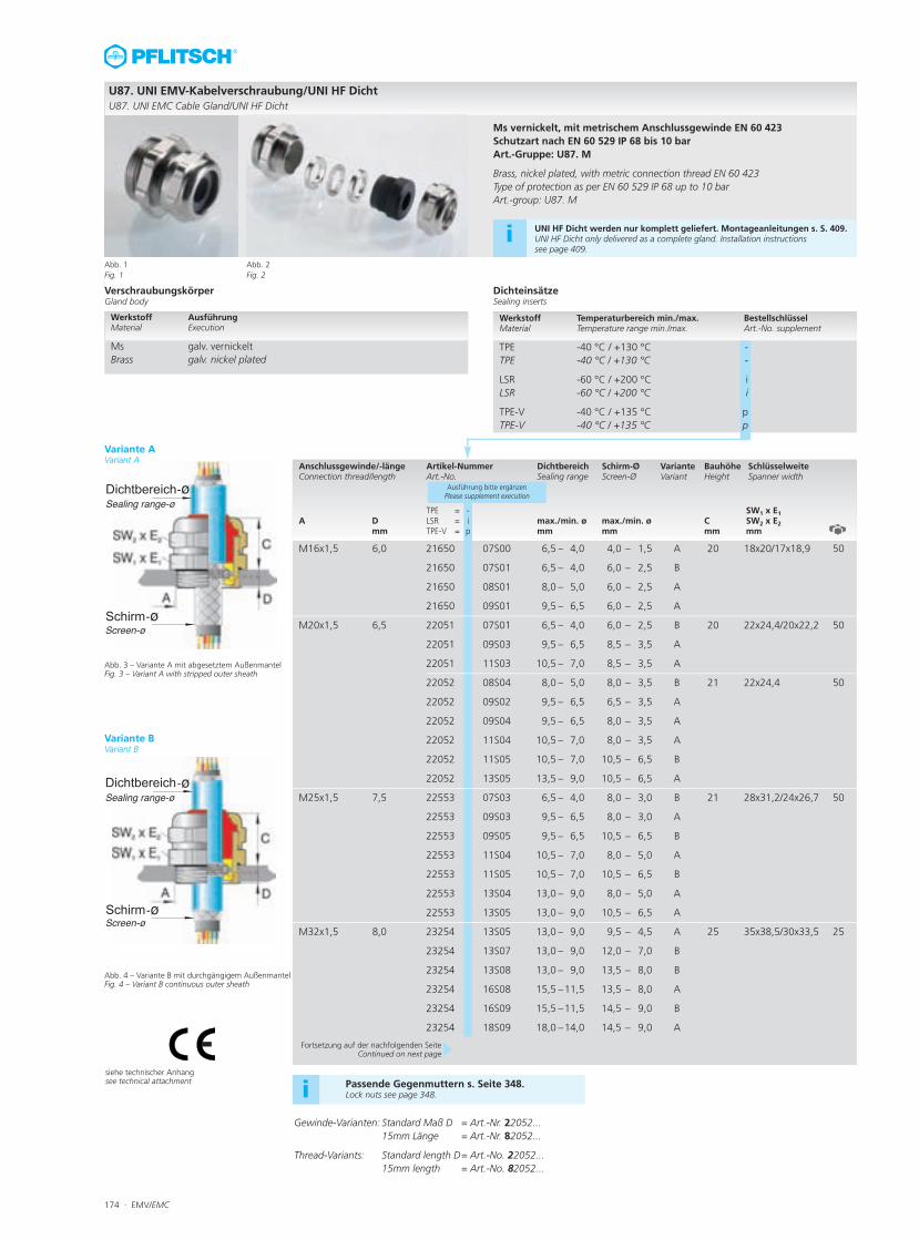
Gewinde-Varianten: Standard Maß D = Art.-Nr. 22052...15mm Länge = Art.-Nr. 82052...
Thread-Variants: Standard length D= Art.-No. 22052...15mm length = Art.-No. 82052...
VerschraubungskörperGland body
Variante AVariant A
Variante BVariant B
DichteinsätzeSealing inserts
Anschlussgewinde/-länge Artikel-Nummer Dichtbereich Schirm-Ø Variante Bauhöhe SchlüsselweiteConnection thread/length Art.-No. Sealing range Screen-Ø Variant Height Spanner width
TPE = - SW1 x E1A D LSR = i max./min. ø max./min. ø C SW2 x E2 mm TPE-V = p mm mm mm mm
Ausführung bitte ergänzenPlease supplement execution
M16x1,5 6,0 21650 07S00 6,5 – 4,0 4,0 – 1,5 A 20 18x20/17x18,9 50
21650 07S01 6,5 – 4,0 6,0 – 2,5 B
21650 08S01 8,0 – 5,0 6,0 – 2,5 A
21650 09S01 9,5 – 6,5 6,0 – 2,5 A
M20x1,5 6,5 22051 07S01 6,5 – 4,0 6,0 – 2,5 B 20 22x24,4/20x22,2 50
22051 09S03 9,5 – 6,5 8,5 – 3,5 A
22051 11S03 10,5 – 7,0 8,5 – 3,5 A
22052 08S04 8,0 – 5,0 8,0 – 3,5 B 21 22x24,4 50
22052 09S02 9,5 – 6,5 6,5 – 3,5 A
22052 09S04 9,5 – 6,5 8,0 – 3,5 A
22052 11S04 10,5 – 7,0 8,0 – 3,5 A
22052 11S05 10,5 – 7,0 10,5 – 6,5 B
22052 13S05 13,5 – 9,0 10,5 – 6,5 A
M25x1,5 7,5 22553 07S03 6,5 – 4,0 8,0 – 3,0 B 21 28x31,2/24x26,7 50
22553 09S03 9,5 – 6,5 8,0 – 3,0 A
22553 09S05 9,5 – 6,5 10,5 – 6,5 B
22553 11S04 10,5 – 7,0 8,0 – 5,0 A
22553 11S05 10,5 – 7,0 10,5 – 6,5 B
22553 13S04 13,0 – 9,0 8,0 – 5,0 A
22553 13S05 13,0 – 9,0 10,5 – 6,5 A
M32x1,5 8,0 23254 13S05 13,0 – 9,0 9,5 – 4,5 A 25 35x38,5/30x33,5 25
23254 13S07 13,0 – 9,0 12,0 – 7,0 B
23254 13S08 13,0 – 9,0 13,5 – 8,0 B
23254 16S08 15,5 –11,5 13,5 – 8,0 A
23254 16S09 15,5 –11,5 14,5 – 9,0 B
23254 18S09 18,0 –14,0 14,5 – 9,0 A
Werkstoff Ausführung Material Execution
Ms galv. vernickelt Brass galv. nickel plated
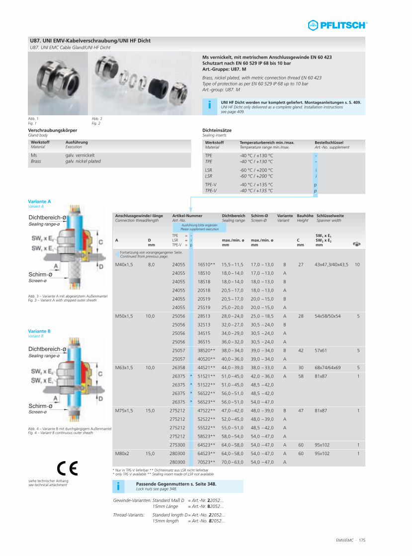
U87. UNI EMV-Kabelverschraubung/UNI HF DichtU87. UNI EMC Cable Gland/UNI HF Dicht
Abb. 1Fig. 1
Abb. 2Fig. 2
Ms vernickelt, mit metrischem Anschlussgewinde EN 60 423Schutzart nach EN 60 529 IP 68 bis 10 barArt.-Gruppe: U87. M
Brass, nickel plated, with metric connection thread EN 60 423Type of protection as per EN 60 529 IP 68 up to 10 barArt.-group: U87. M
i UNI HF Dicht werden nur komplett geliefert. Montageanleitungen s. S. 409.UNI HF Dicht only delivered as a complete gland. Installation instructions see page 409.
Werkstoff Temperaturbereich min./max. BestellschlüsselMaterial Temperature range min./max. Art.-No. supplement
TPE -40 °C / +130 °C -TPE -40 °C / +130 °C -
LSR -60 °C / +200 °C iLSR -60 °C / +200 °C i
TPE-V -40 °C / +135 °C pTPE-V -40 °C / +135 °C p
Fortsetzung auf der nachfolgenden SeiteContinued on next page
Abb. 3 – Variante A mit abgesetztem AußenmantelFig. 3 – Variant A with stripped outer sheath
Abb. 4 – Variante B mit durchgängigem AußenmantelFig. 4 – Variant B continuous outer sheath
siehe technischer Anhangsee technical attachment Passende Gegenmuttern s. Seite 348.
Lock nuts see page 348.i
EMV/EMC · 175
VerschraubungskörperGland body
DichteinsätzeSealing inserts
Anschlussgewinde/-länge Artikel-Nummer Dichtbereich Schirm-Ø Variante Bauhöhe SchlüsselweiteConnection thread/length Art.-No. Sealing range Screen-Ø Variant Height Spanner width
TPE = - SW1 x E1A D LSR = i max./min. ø max./min. ø C SW2 x E2 mm TPE-V = p mm mm mm mm
Ausführung bitte ergänzenPlease supplement execution
M40x1,5 8,0 24055 16S10** 15,5 –11,5 17,0 – 13,0 B 27 43x47,3/40x43,5 10
24055 18S10 18,0 –14,0 17,0 – 13,0 A
24055 18S18 18,0 –14,0 18,0 – 13,0 B
24055 20S18 20,5 –17,0 18,0 – 13,0 A
24055 20S19 20,5 –17,0 20,0 – 15,0 B
24055 25S19 25,0 –20,0 20,0 – 15,0 A
M50x1,5 10,0 25056 28S13 28,0 –24,0 25,0 – 18,5 A 28 54x58/50x54 5
25056 32S13 32,0 –27,0 30,5 – 24,0 B
25056 34S15 34,0 –29,0 30,5 – 24,0 A
25056 36S15 36,0 –32,0 30,5 – 24,0 A
25057 38S20** 38,0 –34,0 39,0 – 34,0 B 42 57x61 5
25057 40S20** 40,0 –36,0 39,0 – 34,0 A
M63x1,5 10,0 26358 44S21** 44,0 –39,0 38,0 – 33,0 A 30 68x74/64x69 5
26375 * 51S21** 51,0 –45,0 42,0 – 36,0 A 58 81x87 1
26375 * 51S22** 51,0 –45,0 48,5 – 42,0
26375 * 56S22** 56,0 –51,0 48,5 – 42,0
26375 * 56S23** 56,0 –51,0 54,0 – 47,0
M75x1,5 15,0 275212 47S22** 47,0 –42,0 48,0 – 39,0 B 47 81x87 1
275212 52S22** 52,0 –45,0 48,0 – 39,0 A
275212 55S22** 55,0 –51,0 48,5 – 42,0 A
275212 58S23** 58,0 –54,0 54,0 – 47,0 A
275300 64S23** 64,0 –58,0 54,0 – 47,0 A 60 95x102 1
M80x2 15,0 280300 64S23** 64,0 –58,0 54,0 – 47,0 A 60 95x102 1
280300 70S23** 70,0 –63,0 54,0 – 47,0 A
Werkstoff Ausführung Material Execution
Ms galv. vernickelt Brass galv. nickel plated
U87. UNI EMV-Kabelverschraubung/UNI HF DichtU87. UNI EMC Cable Gland/UNI HF Dicht
Abb. 1Fig. 1
Abb. 2Fig. 2
Ms vernickelt, mit metrischem Anschlussgewinde EN 60 423Schutzart nach EN 60 529 IP 68 bis 10 barArt.-Gruppe: U87. M
Brass, nickel plated, with metric connection thread EN 60 423Type of protection as per EN 60 529 IP 68 up to 10 barArt.-group: U87. M
Werkstoff Temperaturbereich min./max. BestellschlüsselMaterial Temperature range min./max. Art.-No. supplement
TPE -40 °C / +130 °C -TPE -40 °C / +130 °C -
LSR -60 °C / +200 °C iLSR -60 °C / +200 °C i
TPE-V -40 °C / +135 °C pTPE-V -40 °C / +135 °C p
Fortsetzung von vorangegangener Seite.Continued from previous page.
Abb. 3 – Variante A mit abgesetztem AußenmantelFig. 3 – Variant A with stripped outer sheath
Abb. 4 – Variante B mit durchgängigem AußenmantelFig. 4 – Variant B continuous outer sheath
siehe technischer Anhangsee technical attachment
Variante AVariant A
Variante BVariant B
Gewinde-Varianten: Standard Maß D = Art.-Nr. 22052...15mm Länge = Art.-Nr. 82052...
Thread-Variants: Standard length D= Art.-No. 22052...15mm length = Art.-No. 82052...
Passende Gegenmuttern s. Seite 348.Lock nuts see page 348.i
* Nur in TPE-V lieferbar ** Dichteinsatz aus LSR nicht lieferbar* only TPE-V available ** Sealing insert made of LSR not available
i UNI HF Dicht werden nur komplett geliefert. Montageanleitungen s. S. 409.UNI HF Dicht only delivered as a complete gland. Installation instructions see page 409.
176 · EMV/EMC
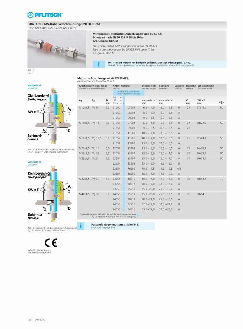
Metrische Anschlussgewinde EN 60 423Metric connection thread EN 60 423
Anschlussgewinde/-länge Artikel-Nummer Dichtbereich Schirm-Ø Variante Bauhöhe SchlüsselweiteConnection thread/length Art.-No. Sealing range Screen-Ø Variant Height Spanner width
TPE = -A1 A2 D LSR = i max./min. ø max./min. ø C SW x E
mm TPE-V = p mm mm mm mm
Ausführung bitte ergänzenPlease supplement execution
M12x1,5 /Pg 9 5,0 21250 07S01 6,5 – 4,0 6,0 – 2,5 B 27 17x18,9 50
21250 08S01 8,0 – 5,0 6,0 – 2,5 A
21250 09S01 9,5 – 6,5 6,0 – 2,5 A
M16x1,5 /Pg 11 6,0 21651 07S01 6,5 – 4,0 6,5 – 2,5 B 27 20x22,2 50
21651 09S03 9,5 – 6,5 8,5 – 3,5 A 28
21651 11S03 10,5 – 7,0 8,5 – 3,5 A
M16x1,5 /Pg 13,5 6,0 21652 11S05 10,5 – 7,0 10,5 – 6,5 B 29 22x24,4 50
21652 13S05 13,0 – 9,0 10,5 – 6,5 A
M20x1,5 /Pg 16 6,5 22053 13S05 13,0 – 9,0 10,5 – 6,5 A 29 24x26,7 50
M20x1,5 /Pg 21 6,5 22054 13S07 13,0 – 9,0 12,0 – 7,0 B 35 30x33,5 50
M25x1,5 /Pg21 6,5 22554 13S07 13,0 – 9,0 12,0 – 7,0 A 35 30x33,5 50
22554 13S08 13,0 – 9,0 13,5 – 8,0 B
22554 16S09 15,5 –11,5 14,5 – 9,5 A/B
22554 18S09 18,0 –14,0 14,5 – 9,0 A
M32x1,5 /Pg 29 8,0 23255 18S10 18,0 –14,0 17,0 – 13,0 B 38 40x43,5 10
23255 20S18 20,5 –17,0 18,0 – 13,0 A
23255 25S19 25,0 –20,0 20,0 – 15,0 A
M40x1,5 /Pg 36 8,0 24056 25S13 25,0 –20,0 25,5 – 18,5 B 39 50x54 5
24056 28S13 28,0 –24,0 25,5 – 18,5 A
24056 32S15 32,0 –27,0 30,5 – 24,0 B
24056 34S15 33,0 –29,0 30,5 – 24,0 A
U87. UNI EMV-Kabelverschraubung/UNI HF Dicht
U87. UNI EMV Cable Gland/UNI HF Dicht
Abb. 1
Fig. 1
Ms vernickelt, metrisches Anschlussgewinde EN 60 423
Schutzart nach EN 60 529 IP 68 bis 10 bar
Art.-Gruppe: U87. M
Brass, nickel plated, Metric connection thread EN 60 423
Type of protection as per EN 60 529 IP 68 up to 10 bar
Art.-group: U87. M
Pg-Anschlussgewinde finden Sie auf der nachfolgenden SeitePg connection thread you will find on next page
Abb. 2 – Variante A mit abgesetztem AußenmantelFig. 2 – Variant A with stripped outer sheath
Abb. 3 – Variante B mit durchgängigem AußenmantelFig. 3 – Variant B continuous outer sheath
siehe technischer Anhangsee technical attachment
Passende Gegenmuttern s. Seite 348.Lock nuts see page 348.i
Variante AVariant A
Variante BVariant B
iUNI HF Dicht werden nur komplett geliefert. Montageanleitungen s. S. 409.UNI HF Dicht only delivered as a complete gland. Installation instructions see page 409.
EMV/EMC · 177
VerschraubungskörperGland body
DichteinsätzeSealing inserts
Anschlussgewinde/-länge Artikel-Nummer Dichtbereich Schirm-Ø Variante Bauhöhe SchlüsselweiteConnection thread/length Art.-No. Sealing range Screen-Ø Variant Height Spanner width
TPE = -A D LSR = i max./min. ø max./min. ø C SW x E mm TPE-V = p mm mm mm mm
Ausführung bitte ergänzenPlease supplement execution
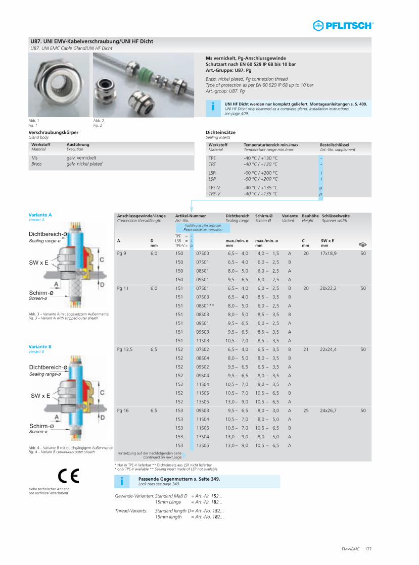
Pg 9 6,0 150 07S00 6,5 – 4,0 4,0 – 1,5 A 20 17x18,9 50
150 07S01 6,5 – 4,0 6,0 – 2,5 B
150 08S01 8,0 – 5,0 6,0 – 2,5 A
150 09S01 9,5 – 6,5 6,0 – 2,5 A
Pg 11 6,0 151 07S01 6,5 – 4,0 6,0 – 2,5 B 20 20x22,2 50
151 07S03 6,5 – 4,0 8,5 – 3,5 B
151 08S01** 8,0 – 5,0 6,0 – 2,5 A
151 08S03 8,0 – 5,0 8,5 – 3,5 B
151 09S01 9,5 – 6,5 6,0 – 2,5 A
151 09S03 9,5 – 6,5 8,5 – 3,5 A
151 11S03 10,5 – 7,0 8,5 – 3,5 A
Pg 13,5 6,5 152 07S02 6,5 – 4,0 6,5 – 3,5 B 21 22x24,4 50
152 08S04 8,0 – 5,0 8,0 – 3,5 B
152 09S02 9,5 – 6,5 6,5 – 3,5 A
152 09S04 9,5 – 6,5 8,0 – 3,5 A
152 11S04 10,5 – 7,0 8,0 – 3,5 A
152 11S05 10,5 – 7,0 10,5 – 6,5 B
152 13S05 13,0 – 9,0 10,5 – 6,5 A
Pg 16 6,5 153 09S03 9,5 – 6,5 8,0 – 3,0 A 25 24x26,7 50
153 11S04 10,5 – 7,0 8,0 – 5,0 A
153 11S05 10,5 – 7,0 10,5 – 6,5 B
153 13S04 13,0 – 9,0 8,0 – 5,0 A
153 13S05 13,0 – 9,0 10,5 – 6,5 A
Werkstoff Ausführung Material Execution
Ms galv. vernickelt Brass galv. nickel plated
U87. UNI EMV-Kabelverschraubung/UNI HF DichtU87. UNI EMC Cable Gland/UNI HF Dicht
Abb. 1Fig. 1
Abb. 2Fig. 2
Ms vernickelt, Pg-AnschlussgewindeSchutzart nach EN 60 529 IP 68 bis 10 barArt.-Gruppe: U87. Pg
Brass, nickel plated, Pg connection threadType of protection as per EN 60 529 IP 68 up to 10 barArt.-group: U87. Pg
Werkstoff Temperaturbereich min./max. BestellschlüsselMaterial Temperature range min./max. Art.-No. supplement
TPE -40 °C / +130 °C -TPE -40 °C / +130 °C -
LSR -60 °C / +200 °C iLSR -60 °C / +200 °C i
TPE-V -40 °C / +135 °C pTPE-V -40 °C / +135 °C p
Abb. 3 – Variante A mit abgesetztem AußenmantelFig. 3 – Variant A with stripped outer sheath
Abb. 4 – Variante B mit durchgängigem AußenmantelFig. 4 – Variant B continuous outer sheath
siehe technischer Anhangsee technical attachment
Passende Gegenmuttern s. Seite 349.Lock nuts see page 349.i
Fortsetzung auf der nachfolgenden SeiteContinued on next page
Variante AVariant A
Variante BVariant B
* Nur in TPE-V lieferbar ** Dichteinsatz aus LSR nicht lieferbar* only TPE-V available ** Sealing insert made of LSR not available
i UNI HF Dicht werden nur komplett geliefert. Montageanleitungen s. S. 409.UNI HF Dicht only delivered as a complete gland. Installation instructions see page 409.
Gewinde-Varianten: Standard Maß D = Art.-Nr. 152...15mm Länge = Art.-Nr. 182...
Thread-Variants: Standard length D= Art.-No. 152...15mm length = Art.-No. 182...
178 · EMV/EMC
siehe technischer Anhangsee technical attachment
VerschraubungskörperGland body
DichteinsätzeSealing inserts
Anschlussgewinde/-länge Artikel-Nummer Dichtbereich Schirm-Ø Variante Bauhöhe SchlüsselweiteConnection thread/length Art.-No. Sealing range Screen-Ø Variant Height Spanner width
TPE = -A D LSR = i max./min. ø max./min. ø C SW x E mm TPE-V = p mm mm mm mm
Ausführung bitte ergänzenPlease supplement execution
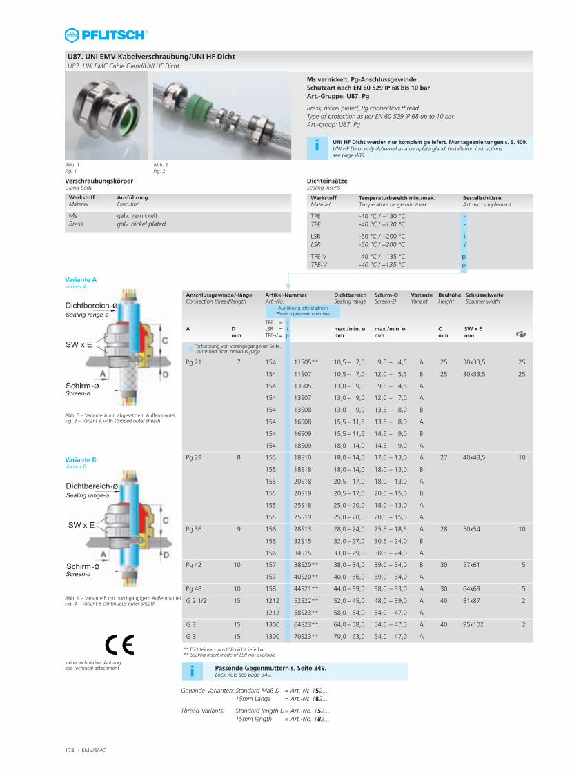
Pg 21 7 154 11S05** 10,5 – 7,0 9,5 – 4,5 A 25 30x33,5 25
154 11S07 10,5 – 7,0 12,0 – 5,5 B 25 30x33,5 25
154 13S05 13,0 – 9,0 9,5 – 4,5 A
154 13S07 13,0 – 9,0 12,0 – 7,0 A
154 13S08 13,0 – 9,0 13,5 – 8,0 B
154 16S08 15,5 – 11,5 13,5 – 8,0 A
154 16S09 15,5 – 11,5 14,5 – 9,0 B
154 18S09 18,0 – 14,0 14,5 – 9,0 A
Pg 29 8 155 18S10 18,0 – 14,0 17,0 – 13,0 A 27 40x43,5 10
155 18S18 18,0 – 14,0 18,0 – 13,0 B
155 20S18 20,5 – 17,0 18,0 – 13,0 A
155 20S19 20,5 – 17,0 20,0 – 15,0 B
155 25S18 25,0 – 20,0 18,0 – 13,0 A
155 25S19 25,0 – 20,0 20,0 – 15,0 A
Pg 36 9 156 28S13 28,0 – 24,0 25,5 – 18,5 A 28 50x54 10
156 32S15 32,0 – 27,0 30,5 – 24,0 B
156 34S15 33,0 – 29,0 30,5 – 24,0 A
Pg 42 10 157 38S20** 38,0 – 34,0 39,0 – 34,0 B 30 57x61 5
157 40S20** 40,0 – 36,0 39,0 – 34,0 A
Pg 48 10 158 44S21** 44,0 – 39,0 38,0 – 33,0 A 30 64x69 5
G 2 1/2 15 1212 52S22** 52,0 – 45,0 48,0 – 39,0 A 40 81x87 2
1212 58S23** 58,0 – 54,0 54,0 – 47,0 A
G 3 15 1300 64S23** 64,0 – 58,0 54,0 – 47,0 A 40 95x102 2
G 3 15 1300 70S23** 70,0 – 63,0 54,0 – 47,0 A
Werkstoff Ausführung Material Execution
Ms galv. vernickelt Brass galv. nickel plated
U87. UNI EMV-Kabelverschraubung/UNI HF DichtU87. UNI EMC Cable Gland/UNI HF Dicht
Abb. 1Fig. 1
Abb. 2Fig. 2
Ms vernickelt, Pg-AnschlussgewindeSchutzart nach EN 60 529 IP 68 bis 10 barArt.-Gruppe: U87. Pg
Brass, nickel plated, Pg connection threadType of protection as per EN 60 529 IP 68 up to 10 barArt.-group: U87. Pg
Werkstoff Temperaturbereich min./max. BestellschlüsselMaterial Temperature range min./max. Art.-No. supplement
TPE -40 °C / +130 °C -TPE -40 °C / +130 °C -
LSR -60 °C / +200 °C iLSR -60 °C / +200 °C i
TPE-V -40 °C / +135 °C pTPE-V -40 °C / +135 °C p
Abb. 3 – Variante A mit abgesetztem AußenmantelFig. 3 – Variant A with stripped outer sheath
Abb. 4 – Variante B mit durchgängigem AußenmantelFig. 4 – Variant B continuous outer sheath
Passende Gegenmuttern s. Seite 349.Lock nuts see page 349.i
Fortsetzung von vorangegangener Seite.Continued from previous page.
Variante AVariant A
Variante BVariant B
** Dichteinsatz aus LSR nicht lieferbar** Sealing insert made of LSR not available
i UNI HF Dicht werden nur komplett geliefert. Montageanleitungen s. S. 409.UNI HF Dicht only delivered as a complete gland. Installation instructions see page 409.
Gewinde-Varianten: Standard Maß D = Art.-Nr. 152...15mm Länge = Art.-Nr. 182...
Thread-Variants: Standard length D= Art.-No. 152...15mm length = Art.-No. 182...
EMV/EMC · 179
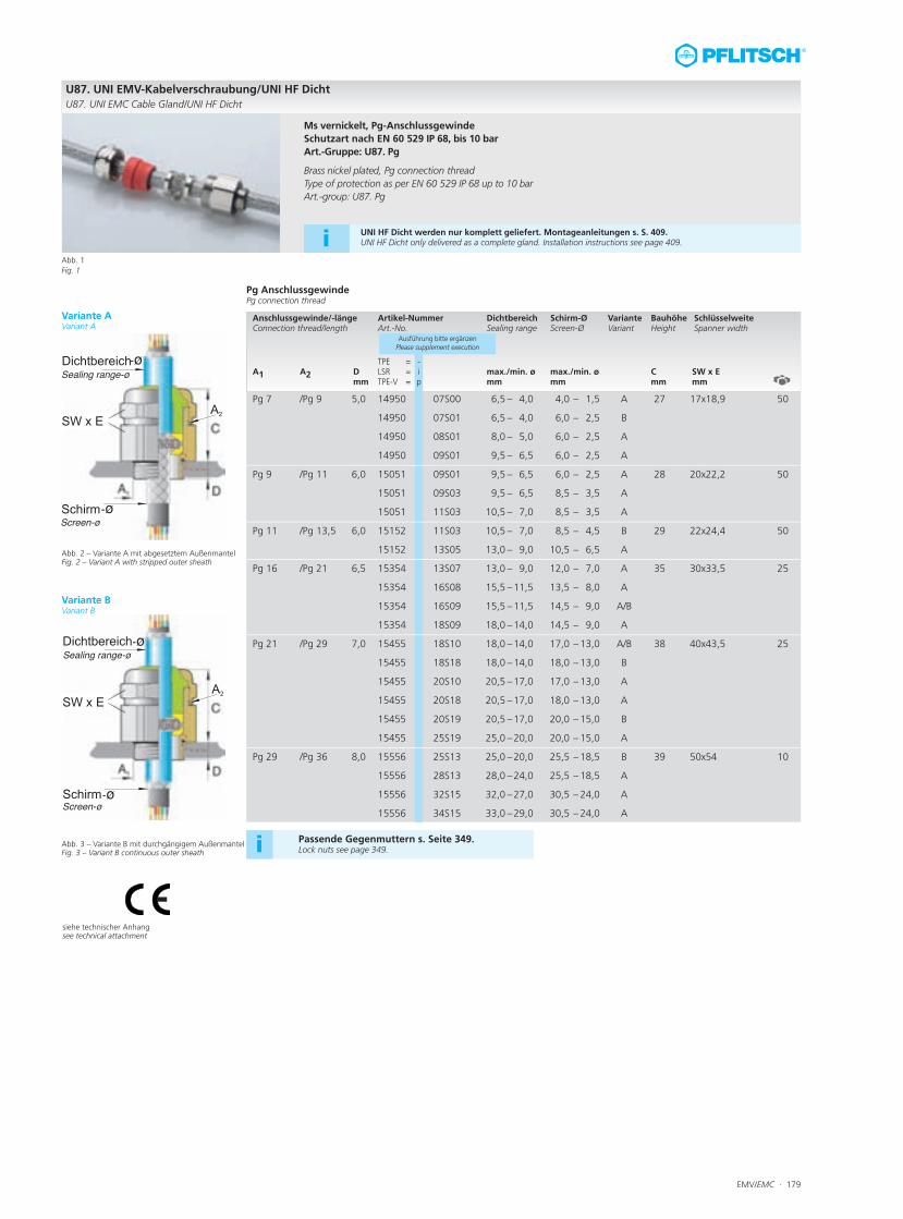
Pg Anschlussgewinde Pg connection thread
Anschlussgewinde/-länge Artikel-Nummer Dichtbereich Schirm-Ø Variante Bauhöhe SchlüsselweiteConnection thread/length Art.-No. Sealing range Screen-Ø Variant Height Spanner width
TPE = -A1 A2 D LSR = i max./min. ø max./min. ø C SW x E
mm TPE-V = p mm mm mm mm
Ausführung bitte ergänzenPlease supplement execution
Pg 7 /Pg 9 5,0 14950 07S00 6,5 – 4,0 4,0 – 1,5 A 27 17x18,9 50
14950 07S01 6,5 – 4,0 6,0 – 2,5 B
14950 08S01 8,0 – 5,0 6,0 – 2,5 A
14950 09S01 9,5 – 6,5 6,0 – 2,5 A
Pg 9 /Pg 11 6,0 15051 09S01 9,5 – 6,5 6,0 – 2,5 A 28 20x22,2 50
15051 09S03 9,5 – 6,5 8,5 – 3,5 A
15051 11S03 10,5 – 7,0 8,5 – 3,5 A
Pg 11 /Pg 13,5 6,0 15152 11S03 10,5 – 7,0 8,5 – 4,5 B 29 22x24,4 50
15152 13S05 13,0 – 9,0 10,5 – 6,5 A
Pg 16 /Pg 21 6,5 15354 13S07 13,0 – 9,0 12,0 – 7,0 A 35 30x33,5 25
15354 16S08 15,5 –11,5 13,5 – 8,0 A
15354 16S09 15,5 –11,5 14,5 – 9,0 A/B
15354 18S09 18,0 –14,0 14,5 – 9,0 A
Pg 21 /Pg 29 7,0 15455 18S10 18,0 –14,0 17,0 – 13,0 A/B 38 40x43,5 25
15455 18S18 18,0 –14,0 18,0 – 13,0 B
15455 20S10 20,5 –17,0 17,0 – 13,0 A
15455 20S18 20,5 –17,0 18,0 – 13,0 A
15455 20S19 20,5 –17,0 20,0 – 15,0 B
15455 25S19 25,0 –20,0 20,0 – 15,0 A
Pg 29 /Pg 36 8,0 15556 25S13 25,0 –20,0 25,5 – 18,5 B 39 50x54 10
15556 28S13 28,0 –24,0 25,5 – 18,5 A
15556 32S15 32,0 –27,0 30,5 – 24,0 A
15556 34S15 33,0 –29,0 30,5 – 24,0 A
U87. UNI EMV-Kabelverschraubung/UNI HF DichtU87. UNI EMC Cable Gland/UNI HF Dicht
Abb. 1Fig. 1
Ms vernickelt, Pg-AnschlussgewindeSchutzart nach EN 60 529 IP 68, bis 10 barArt.-Gruppe: U87. Pg
Brass nickel plated, Pg connection threadType of protection as per EN 60 529 IP 68 up to 10 barArt.-group: U87. Pg
Abb. 2 – Variante A mit abgesetztem AußenmantelFig. 2 – Variant A with stripped outer sheath
Abb. 3 – Variante B mit durchgängigem AußenmantelFig. 3 – Variant B continuous outer sheath
siehe technischer Anhangsee technical attachment
Passende Gegenmuttern s. Seite 349.Lock nuts see page 349.i
Variante AVariant A
Variante BVariant B
i UNI HF Dicht werden nur komplett geliefert. Montageanleitungen s. S. 409.UNI HF Dicht only delivered as a complete gland. Installation instructions see page 409.
180 · EMV/EMC
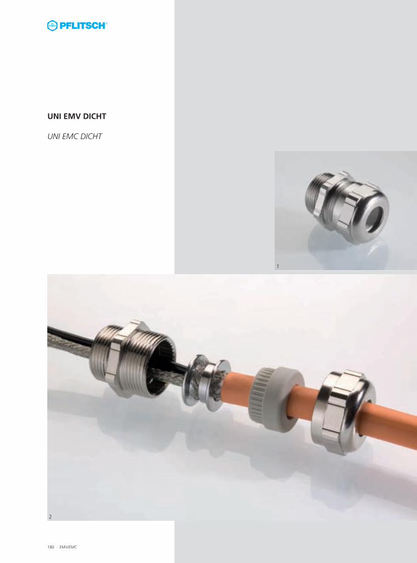
UNI EMV DICHT
UNI EMC DICHT
1
2
EMV/EMC · 181
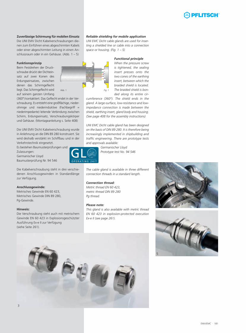
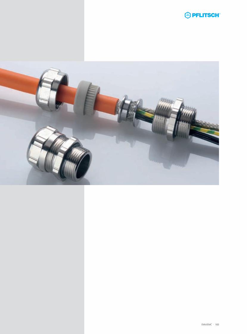
Reliable shielding for mobile applicationUNI EMC Dicht cable glands are used for inser-ting a shielded line or cable into a connectionspace or housing. (Fig. 1 – 5)
Functional principleWhen the pressure screwis tightened, the sealinginsert presses onto thetwo cones of the earthinginsert, between which thebraided shield is located.The braided shield is bon-ded along its entire cir-
cumference (360°). The shield ends in thegland. A large-surface, low-resistance and low-impedance connection is made between theshield, earthing insert, gland body and housing.(See page 408 for the assembly instructions)
UNI EMC Dicht cable gland has been designedon the basis of DIN 89 280. It is therefore beingincreasingly implemented in shipbuilding andtraffic engineering. There are prototype testsand approvals available:
Germanischer LloydPrototype test No. 94 546
The cable gland is available in three differentconnection threads in a standard length.
Connection thread:Metric thread EN 60 423, metric thread DIN 89 280Pg thread.
Please note:This gland is also available with metric threadEN 60 423 in explosion-protected execution Ex-e II (see page 261).
Zuverlässige Schirmung für mobilen EinsatzDie UNI EMV Dicht Kabelverschraubungen die-nen zum Einführen eines abgeschirmten Kabelsoder einer abgeschirmten Leitung in einen An-schlussraum oder in ein Gehäuse. (Abb. 1 – 5)
FunktionsprinzipBeim Festdrehen der Druck-schraube drückt der Dichtein-satz auf zwei Konen desErdungseinsatzes, zwischendenen das Schirmgeflechtliegt. Das Schirmgeflecht wirdauf seinem ganzen Umfang(360°) kontaktiert. Das Geflecht endet in der Ver-schraubung. Es entsteht eine großflächige, nieder-ohmige und niederinduktive (Fachbegriff =niederimpedante) leitende Verbindung zwischenSchirm, Erdungseinsatz, Verschraubungskörperund Gehäuse. (Montageanleitung s. Seite 408)
Die UNI EMV Dicht Kabelverschraubung wurdein Anlehnung an die DIN 89 280 konstruiert. Siewird deshalb verstärkt im Schiffbau und in derVerkehrstechnik eingesetzt. Es bestehen Baumusterprüfungen undZulassungen:Germanischer LloydBaumusterprüfung Nr. 94 546
Die Kabelverschraubung steht in drei verschie-denen Anschlussgewinden in Standardlängezur Verfügung.
Anschlussgewinde:Metrisches Gewinde EN 60 423, Metrisches Gewinde DIN 89 280,Pg-Gewinde.
Hinweis:Die Verschraubung steht auch mit metrischemGewinde EN 60 423 in ExplosionsgeschützterAusführung Ex-e II zur Verfügung (siehe Seite 261).
4
5
3
Abb. 1 Fig. 1
182 · EMV/EMC
Abb. 3Fig. 3
Abb. 4Fig. 4
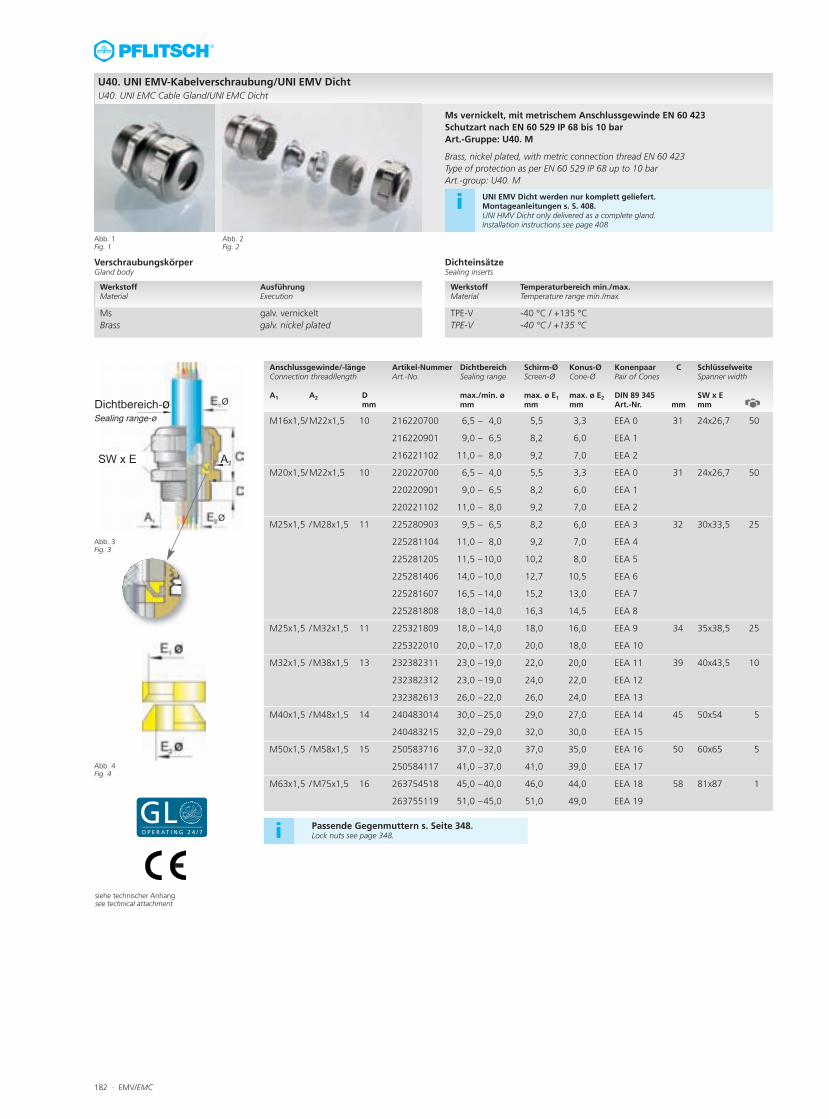
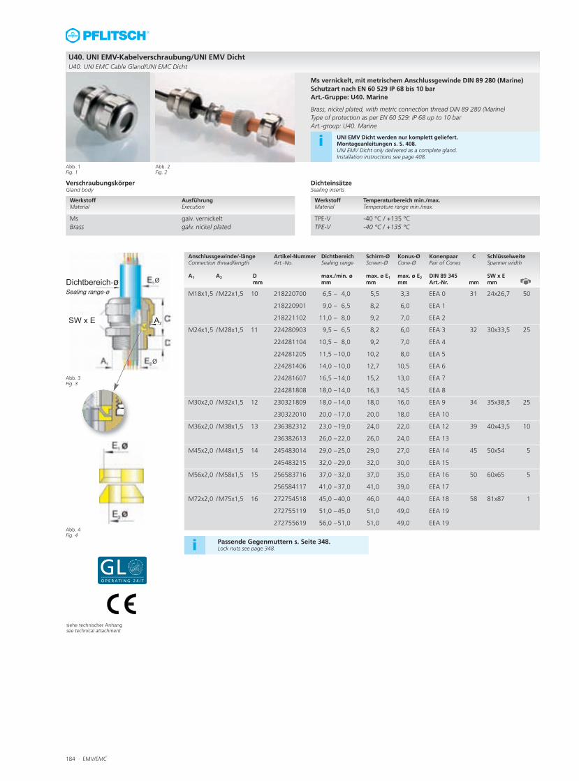
U40. UNI EMV-Kabelverschraubung/UNI EMV DichtU40. UNI EMC Cable Gland/UNI EMC Dicht
Anschlussgewinde/-länge Artikel-Nummer Dichtbereich Schirm-Ø Konus-Ø Konenpaar C SchlüsselweiteConnection thread/length Art.-No. Sealing range Screen-Ø Cone-Ø Pair of Cones Spanner width A1 A2 D max./min. ø max. ø E1 max. ø E2 DIN 89 345 SW x E
mm mm mm mm Art.-Nr. mm mm
M16x1,5/M22x1,5 10 216220700 6,5 – 4,0 5,5 3,3 EEA 0 31 24x26,7 50
216220901 9,0 – 6,5 8,2 6,0 EEA 1
216221102 11,0 – 8,0 9,2 7,0 EEA 2
M20x1,5/M22x1,5 10 220220700 6,5 – 4,0 5,5 3,3 EEA 0 31 24x26,7 50
220220901 9,0 – 6,5 8,2 6,0 EEA 1
220221102 11,0 – 8,0 9,2 7,0 EEA 2
M25x1,5 /M28x1,5 11 225280903 9,5 – 6,5 8,2 6,0 EEA 3 32 30x33,5 25
225281104 11,0 – 8,0 9,2 7,0 EEA 4
225281205 11,5 –10,0 10,2 8,0 EEA 5
225281406 14,0 –10,0 12,7 10,5 EEA 6
225281607 16,5 –14,0 15,2 13,0 EEA 7
225281808 18,0 –14,0 16,3 14,5 EEA 8
M25x1,5 /M32x1,5 11 225321809 18,0 –14,0 18,0 16,0 EEA 9 34 35x38,5 25
225322010 20,0 –17,0 20,0 18,0 EEA 10
M32x1,5 /M38x1,5 13 232382311 23,0 –19,0 22,0 20,0 EEA 11 39 40x43,5 10
232382312 23,0 –19,0 24,0 22,0 EEA 12
232382613 26,0 –22,0 26,0 24,0 EEA 13
M40x1,5 /M48x1,5 14 240483014 30,0 –25,0 29,0 27,0 EEA 14 45 50x54 5
240483215 32,0 –29,0 32,0 30,0 EEA 15
M50x1,5 /M58x1,5 15 250583716 37,0 –32,0 37,0 35,0 EEA 16 50 60x65 5
250584117 41,0 –37,0 41,0 39,0 EEA 17
M63x1,5 /M75x1,5 16 263754518 45,0 –40,0 46,0 44,0 EEA 18 58 81x87 1
263755119 51,0 –45,0 51,0 49,0 EEA 19
Abb. 1Fig. 1
Abb. 2Fig. 2
siehe technischer Anhangsee technical attachment
Ms vernickelt, mit metrischem Anschlussgewinde EN 60 423Schutzart nach EN 60 529 IP 68 bis 10 bar Art.-Gruppe: U40. M
Brass, nickel plated, with metric connection thread EN 60 423Type of protection as per EN 60 529 IP 68 up to 10 bar Art.-group: U40. M
i UNI EMV Dicht werden nur komplett geliefert. Montageanleitungen s. S. 408.UNI HMV Dicht only delivered as a complete gland. Installation instructions see page 408
VerschraubungskörperGland body
DichteinsätzeSealing inserts
Werkstoff Temperaturbereich min./max. Material Temperature range min./max.
TPE-V -40 °C / +135 °C TPE-V -40 °C / +135 °C
Werkstoff Ausführung Material Execution
Ms galv. vernickelt Brass galv. nickel plated
Passende Gegenmuttern s. Seite 348.Lock nuts see page 348.i
EMV/EMC · 183
184 · EMV/EMC
Abb. 3Fig. 3
Abb. 4Fig. 4
U40. UNI EMV-Kabelverschraubung/UNI EMV DichtU40. UNI EMC Cable Gland/UNI EMC Dicht
Anschlussgewinde/-länge Artikel-Nummer Dichtbereich Schirm-Ø Konus-Ø Konenpaar C SchlüsselweiteConnection thread/length Art.-No. Sealing range Screen-Ø Cone-Ø Pair of Cones Spanner width A1 A2 D max./min. ø max. ø E1 max. ø E2 DIN 89 345 SW x E
mm mm mm mm Art.-Nr. mm mm
M18x1,5 /M22x1,5 10 218220700 6,5 – 4,0 5,5 3,3 EEA 0 31 24x26,7 50
218220901 9,0 – 6,5 8,2 6,0 EEA 1
218221102 11,0 – 8,0 9,2 7,0 EEA 2
M24x1,5 /M28x1,5 11 224280903 9,5 – 6,5 8,2 6,0 EEA 3 32 30x33,5 25
224281104 10,5 – 8,0 9,2 7,0 EEA 4
224281205 11,5 –10,0 10,2 8,0 EEA 5
224281406 14,0 –10,0 12,7 10,5 EEA 6
224281607 16,5 –14,0 15,2 13,0 EEA 7
224281808 18,0 –14,0 16,3 14,5 EEA 8
M30x2,0 /M32x1,5 12 230321809 18,0 –14,0 18,0 16,0 EEA 9 34 35x38,5 25
230322010 20,0 –17,0 20,0 18,0 EEA 10
M36x2,0 /M38x1,5 13 236382312 23,0 –19,0 24,0 22,0 EEA 12 39 40x43,5 10
236382613 26,0 –22,0 26,0 24,0 EEA 13
M45x2,0 /M48x1,5 14 245483014 29,0 –25,0 29,0 27,0 EEA 14 45 50x54 5
245483215 32,0 –29,0 32,0 30,0 EEA 15
M56x2,0 /M58x1,5 15 256583716 37,0 –32,0 37,0 35,0 EEA 16 50 60x65 5
256584117 41,0 –37,0 41,0 39,0 EEA 17
M72x2,0 /M75x1,5 16 272754518 45,0 –40,0 46,0 44,0 EEA 18 58 81x87 1
272755119 51,0 –45,0 51,0 49,0 EEA 19
272755619 56,0 –51,0 51,0 49,0 EEA 19
Abb. 1Fig. 1
Abb. 2Fig. 2
Ms vernickelt, mit metrischem Anschlussgewinde DIN 89 280 (Marine)Schutzart nach EN 60 529 IP 68 bis 10 bar Art.-Gruppe: U40. Marine
Brass, nickel plated, with metric connection thread DIN 89 280 (Marine)Type of protection as per EN 60 529: IP 68 up to 10 bar Art.-group: U40. Marine
i UNI EMV Dicht werden nur komplett geliefert. Montageanleitungen s. S. 408.UNI EMV Dicht only delivered as a complete gland. Installation instructions see page 408.
VerschraubungskörperGland body
DichteinsätzeSealing inserts
Werkstoff Temperaturbereich min./max. Material Temperature range min./max.
TPE-V -40 °C / +135 °C TPE-V -40 °C / +135 °C
Werkstoff Ausführung Material Execution
Ms galv. vernickelt Brass galv. nickel plated
Passende Gegenmuttern s. Seite 348.Lock nuts see page 348.i
siehe technischer Anhangsee technical attachment
EMV/EMC · 185
Abb. 3Fig. 3
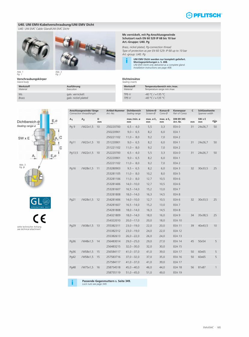
U40. UNI EMV-Kabelverschraubung/UNI EMV DichtU40. UNI EMC Cable Gland/UNI EMC Dicht
Anschlussgewinde/-länge Artikel-Nummer Dichtbereich Schirm-Ø Konus-Ø Konenpaar C SchlüsselweiteConnection thread/length Art.-No. Sealing range Screen-Ø Cone-Ø Pair of Cones Spanner width A1 A2 D max./min. ø max. ø E1 max. ø E2 DIN 89 345 SW x E
mm mm mm mm Art.-Nr. mm mm
Pg 9 /M22x1,5 10 250220700 6,5 – 4,0 5,5 3,3 EEA 0 31 24x26,7 50
250220901 9,0 – 6,5 8,2 6,0 EEA 1
250221102 11,0 – 8,0 9,2 7,0 EEA 2
Pg11 /M22x1,5 10 251220901 9,0 – 6,5 8,2 6,0 EEA 1 31 24x26,7 50
251221102 11,0 – 8,0 9,2 7,0 EEA 2
Pg13,5 /M22x1,5 10 252220700 6,5 – 4,0 5,5 3,3 EEA 0 31 24x26,7 50
252220901 9,0 – 6,5 8,2 6,0 EEA 1
252221102 11,0 – 8,0 9,2 7,0 EEA 2
Pg16 /M28x1,5 11 253280903 9,5 – 6,5 8,2 6,0 EEA 3 32 30x33,5 25
253281105 11,0 – 8,0 10,2 8,0 EEA 5
253281106 11,0 – 8,0 12,7 10,5 EEA 6
253281406 14,0 –10,0 12,7 10,5 EEA 6
253281607 16,5 –14,0 15,2 13,0 EEA 7
253281808 18,0 –14,0 16,3 14,5 EEA 8
Pg21 /M28x1,5 12 254281406 14,0 –10,0 12,7 10,5 EEA 6 32 30x33,5 25
254281607 16,5 –14,0 15,2 13,0 EEA 7
254281808 18,0 –14,0 16,3 14,5 EEA 8
254321809 18,0 –14,0 18,0 16,0 EEA 9 34 35x38,5 25
254322010 20,0 –17,0 20,0 18,0 EEA 10
Pg29 /M38x1,5 13 255382311 23,0 –19,0 22,0 20,0 EEA 11 39 40x43,5 10
255382312 23,0 –19,0 24,0 22,0 EEA 12
255382613 26,0 –22,0 26,0 24,0 EEA 13
Pg36 /M48x1,5 14 256483014 29,0 –25,0 29,0 27,0 EEA 14 45 50x54 5
256483215 32,0 –30,0 32,0 30,0 EEA 15
Pg36 /M58x1,5 15 256584117 41,0 –37,0 41,0 39,0 EEA 17 50 60x65 5
Pg42 /M58x1,5 15 257583716 37,0 –32,0 37,0 35,0 EEA 16 50 60x65 5
257584117 41,0 –37,0 41,0 39,0 EEA 17
Pg48 /M75x1,5 16 258754518 45,0 –40,0 46,0 44,0 EEA 18 56 81x87 1
258755119 51,0 –45,0 51,0 49,0 EEA 19
Abb. 1Fig. 1
Abb. 2Fig. 2
Ms vernickelt, mit Pg-Anschlussgewinde Schutzart nach EN 60 529 IP 68 bis 10 bar Art.-Gruppe: U40. Pg
Brass, nickel plated, Pg-connection threadType of protection as per EN 60 529: IP 68 up to 10 bar Art.-group: U40. Pg
VerschraubungskörperGland body
DichteinsätzeSealing inserts
Werkstoff Temperaturbereich min./max. Material Temperature range min./max.
TPE-V -40 °C / +135 °C TPE-V -40 °C / +135 °C
Werkstoff Ausführung Material Execution
Ms galv. vernickelt Brass galv. nickel plated
Passende Gegenmuttern s. Seite 349.Lock nuts see page 349.i
siehe technischer Anhangsee technical attachment
i UNI EMV Dicht werden nur komplett geliefert. Montageanleitungen s. S. 408.UNI EMV Dicht only delivered as a complete gland. Installation instructions see page 408.
186 · EMV/EMC
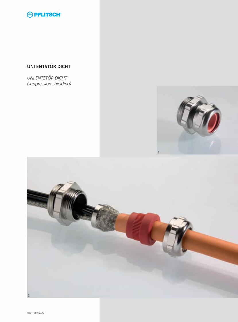
UNI ENTSTÖR DICHT
UNI ENTSTÖR DICHT (suppression shielding)
1
2
EMV/EMC · 187
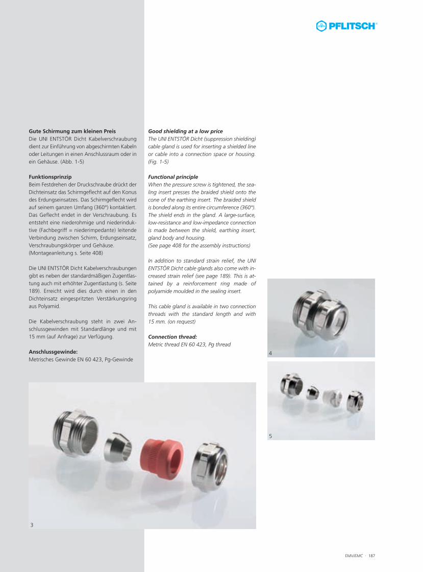
Good shielding at a low priceThe UNI ENTSTÖR Dicht (suppression shielding)cable gland is used for inserting a shielded lineor cable into a connection space or housing.(Fig. 1-5)
Functional principleWhen the pressure screw is tightened, the sea-ling insert presses the braided shield onto thecone of the earthing insert. The braided shieldis bonded along its entire circumference (360°).The shield ends in the gland. A large-surface,low-resistance and low-impedance connectionis made between the shield, earthing insert,gland body and housing.(See page 408 for the assembly instructions)
In addition to standard strain relief, the UNIENTSTÖR Dicht cable glands also come with in-creased strain relief (see page 189). This is at-tained by a reinforcement ring made ofpolyamide moulded in the sealing insert.
This cable gland is available in two connectionthreads with the standard length and with15 mm. (on request)
Connection thread:Metric thread EN 60 423, Pg thread
Gute Schirmung zum kleinen PreisDie UNI ENTSTÖR Dicht Kabelverschraubungdient zur Einführung von abgeschirmten Kabelnoder Leitungen in einen Anschlussraum oder inein Gehäuse. (Abb. 1-5)
FunktionsprinzipBeim Festdrehen der Druckschraube drückt derDichteinsatz das Schirmgeflecht auf den Konusdes Erdungseinsatzes. Das Schirmgeflecht wirdauf seinem ganzen Umfang (360°) kontaktiert.Das Geflecht endet in der Verschraubung. Esentsteht eine niederohmige und niederinduk-tive (Fachbegriff = niederimpedante) leitendeVerbindung zwischen Schirm, Erdungseinsatz,Verschraubungskörper und Gehäuse.(Montageanleitung s. Seite 408)
Die UNI ENTSTÖR Dicht Kabelverschraubungengibt es neben der standardmäßigen Zugentlas-tung auch mit erhöhter Zugentlastung (s. Seite189). Erreicht wird dies durch einen in denDichteinsatz eingespritzten Verstärkungsringaus Polyamid.
Die Kabelverschraubung steht in zwei An-schlussgewinden mit Standardlänge und mit15 mm (auf Anfrage) zur Verfügung.
Anschlussgewinde:Metrisches Gewinde EN 60 423, Pg-Gewinde
4
5
3
188 · EMV/EMC
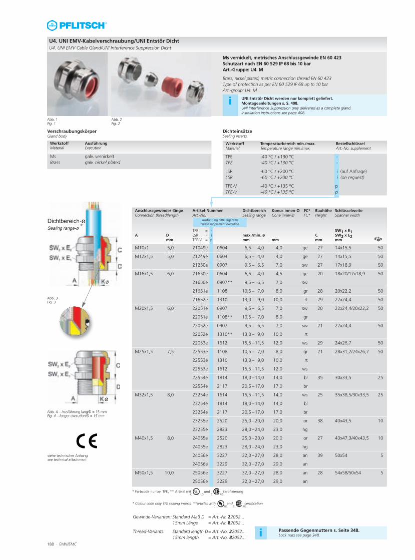
Anschlussgewinde/-länge Artikel-Nummer Dichtbereich Konus innen-Ø FC* Bauhöhe SchlüsselweiteConnection thread/length Art.-No. Sealing range Cone inner-Ø FC* Height Spanner width
TPE = - SW1 x E1A D LSR = i max./min. ø C SW2 x E2
mm TPE-V = p mm mm mm mm
Ausführung bitte ergänzenPlease supplement execution
M10x1 5,0 21049e 0604 6,5 – 4,0 4,0 ge 27 14x15,5 50
M12x1,5 5,0 21249e 0604 6,5 – 4,0 4,0 ge 27 14x15,5 50
21250e 0907 9,5 – 6,5 7,0 sw 27 17x18,9 50
M16x1,5 6,0 21650e 0604 6,5 – 4,0 4,5 ge 20 18x20/17x18,9 50
21650e 0907** 9,5 – 6,5 7,0 sw
21651e 1108 10,5 – 7,0 8,0 gr 28 20x22,2 50
21652e 1310 13,0 – 9,0 10,0 rt 29 22x24,4 50
M20x1,5 6,0 22051e 0907 9,5 – 6,5 7,0 sw 20 22x24,4/20x22,2 50
22051e 1108** 10,5 – 7,0 8,0 gr
22052e 0907 9,5 – 6,5 7,0 sw 21 22x24,4 50
22052e 1310** 13,0 – 9,0 10,0 rt
22053e 1612 15,5 –11,5 12,0 ws 29 24x26,7 50
M25x1,5 7,5 22553e 1108 10,5 – 7,0 8,0 gr 21 28x31,2/24x26,7 50
22553e 1310 13,0 – 9,0 10,0 rt
22553e 1612 15,5 –11,5 12,0 ws
22554e 1814 18,0 –14,0 14,0 bl 35 30x33,5 25
22554e 2117 20,5 –17,0 17,0 br
M32x1,5 8,0 23254e 1614 15,5 –11,5 14,0 ws 25 35x38,5/30x33,5 25
23254e 1814 18,0 –14,0 14,0 bl
23254e 2117 20,5 –17,0 17,0 br
23255e 2520 25,0 –20,0 20,0 or 38 40x43,5 10
23255e 2823 28,0 –24,0 23,0 hg
M40x1,5 8,0 24055e 2520 25,0 –20,0 20,0 or 27 43x47,3/40x43,5 10
24055e 2823 28,0 –24,0 23,0 hg
24056e 3227 32,0 –27,0 28,0 an 39 50x54 5
24056e 3229 32,0 –27,0 29,0 an
M50x1,5 10,0 25056e 3227 32,0 –27,0 28,0 an 28 54x58/50x54 5
25056e 3229 32,0 –27,0 29,0 an
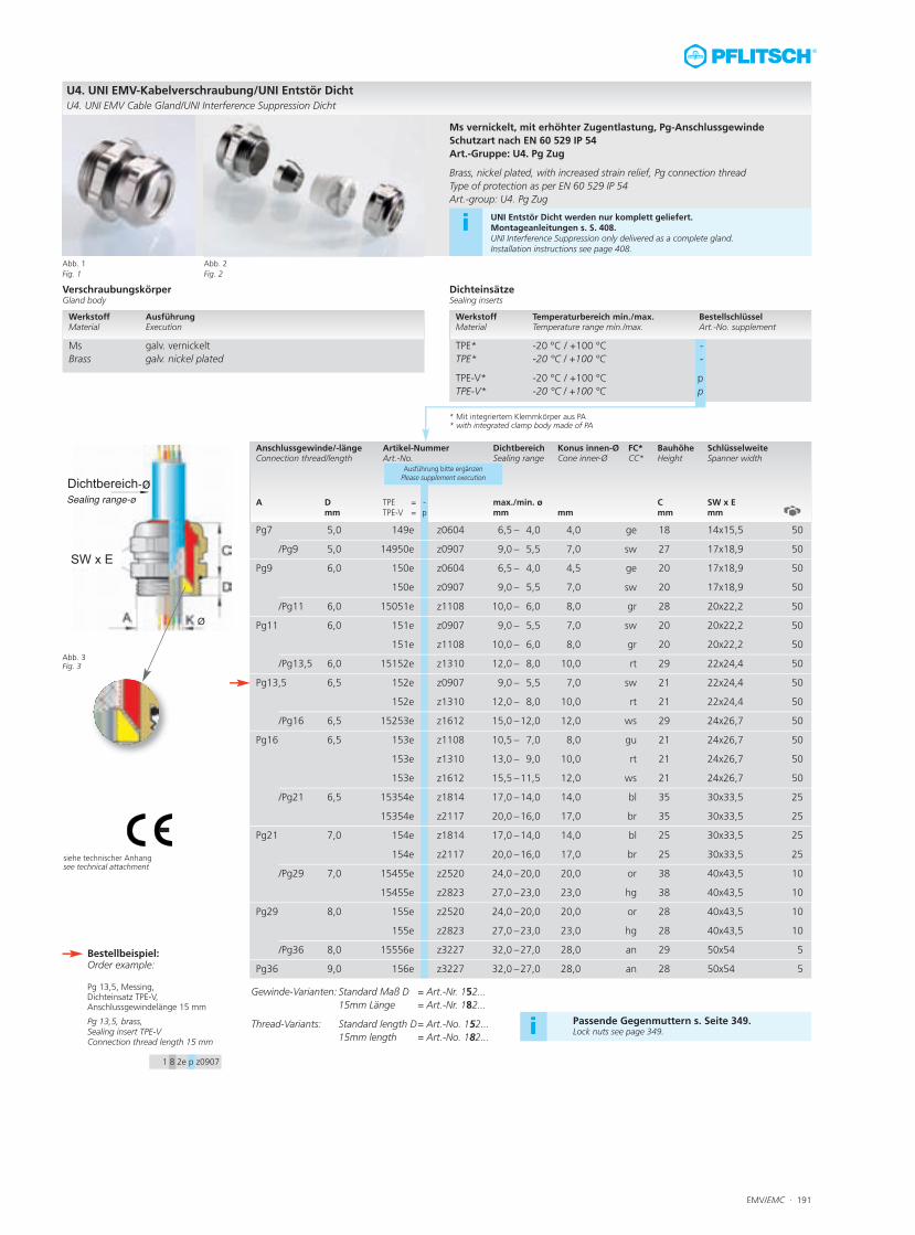
U4. UNI EMV-Kabelverschraubung/UNI Entstör DichtU4. UNI EMV Cable Gland/UNI Interference Suppression Dicht
Abb. 1Fig. 1
Abb. 2Fig. 2
Ms vernickelt, metrisches Anschlussgewinde EN 60 423Schutzart nach EN 60 529 IP 68 bis 10 barArt.-Gruppe: U4. M
Brass, nickel plated, metric connection thread EN 60 423Type of protection as per EN 60 529 IP 68 up to 10 barArt.-group: U4. M
Abb. 3 Fig. 3
Abb. 4 – Ausführung lang/D = 15 mmFig. 4 – longer execution/D = 15 mm
Passende Gegenmuttern s. Seite 348.Lock nuts see page 348.i
VerschraubungskörperGland body
DichteinsätzeSealing inserts
Werkstoff Ausführung Material Execution
Ms galv. vernickelt Brass galv. nickel plated
Werkstoff Temperaturbereich min./max. BestellschlüsselMaterial Temperature range min./max. Art.-No. supplement
TPE -40 °C / +130 °C -TPE -40 °C / +130 °C -
LSR -60 °C / +200 °C i (auf Anfrage)LSR -60 °C / +200 °C i (on request)
TPE-V -40 °C / +135 °C pTPE-V -40 °C / +135 °C p
i UNI Entstör Dicht werden nur komplett geliefert. Montageanleitungen s. S. 408.UNI Interference Suppression only delivered as a complete gland. Installation instructions see page 408.
Gewinde-Varianten: Standard Maß D = Art.-Nr. 22052...15mm Länge = Art.-Nr. 82052...
Thread-Variants: Standard length D= Art.-No. 22052...15mm length = Art.-No. 82052...
* Farbcode nur bei TPE, ** Artikel mit und Zertifizierung
* Colour code only TPE sealing inserts, **articles with and certification
C US C US
C US C US
siehe technischer Anhangsee technical attachment
EMV/EMC · 189
Passende Gegenmuttern s. Seite 348.Lock nuts see page 348.i
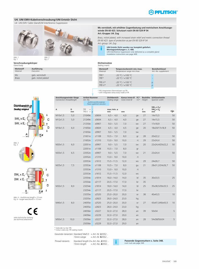
Anschlussgewinde/-länge Artikel-Nummer Dichtbereich Konus innen-Ø FC* Bauhöhe SchlüsselweiteConnection thread/length Art.-No. Sealing range Cone inner-Ø CC* Height Spanner width
SW1 x E1/A D TPE = - max./min. ø C SW2 x E2
mm TPE-V = p mm mm mm mm
Ausführung bitte ergänzenPlease supplement execution
M10x1,5 5,0 21049e z0604 6,5 – 4,0 4,0 ge 27 14x15,5 50
M12x1,5 5,0 21249e z0604 6,5 – 4,0 4,0 ge 27 14x15,5 50
21250e z0907 9,0 – 5,5 7,0 sw 27 17x18,9 50
M16x1,5 6,0 21650e z0604 6,5 – 4,0 4,5 ge 20 18x20/17x18,9 50
21650e z0907 9,0 – 5,5 7,0 sw
21651e z1108 10,5 – 7,0 8,0 gr 28 20x22,2 50
21652e z1310 13,0 – 9,0 10,0 rt 29 22x24,4 50
M20x1,5 6,0 22051e z0907 9,0 – 5,5 7,0 sw 20 22x24,4/20x22,2 50
22051e z1108 10,5 – 7,0 8,0 gr
M20x1,5 6,5 22052e z0907 9,0 – 5,5 7,0 sw 21 22x24,4 50
22052e z1310 13,0 – 9,0 10,0 rt
22053e z1612 15,5 –11,5 12,0 ws 29 24x26,7 50
M25x1,5 7,5 22553e z1108 10,5 – 7,0 8,0 gu 21 28x31,2/24x26,7 50
22553e z1310 13,0 – 9,0 10,0 rt
22553e z1612 15,5 –11,5 12,0 ws
22554e z1814 18,0 –14,0 14,0 bl 35 30x33,5 25
22554e z2117 20,5 –17,0 17,0 br 35
M32x1,5 8,0 23254e z1814 18,0 –14,0 14,0 bl 25 35x38,5/30x33,5 25
23254e z2117 20,5 –17,0 17,0 br
23255e z2520 25,0 –20,0 20,0 or 38 40x43,5 10
23255e z2823 28,0 –24,0 23,0 hg
M40x1,5 8,0 24055e z2520 25,0 –20,0 20,0 or 27 43x47,3/40x43,5 10
24055e z2823 28,0 –24,0 23,0 hg
24056e z3227 32,0 –27,0 28,0 an 39 50x54 5
24056e z3229 32,0 –27,0 29,0 an
M50x1,5 10,0 25056e z3227 32,0 –27,0 28,0 an 28 54x58/50x54 5
25056e z3229 32,0 –27,0 29,0 an
U4. UNI EMV-Kabelverschraubung/UNI Entstör Dicht
U4. UNI EMV Cable Gland/UNI Interference Suppression
Abb. 1Fig. 1
Abb. 2Fig. 2
Ms vernickelt, mit erhöhter Zugentlastung und metrischem Anschlussge-
winde EN 60 423. Schutzart nach EN 60 529 IP 54
Art.-Gruppe: U4. Zug
Brass, nickel plated, with increased strain relief and metric connection thread
EN 60 423. type of protection as per EN 60 529 IP 54
Art.-group: U4. Zug
Abb. 3 Fig. 3
Abb. 4 – Ausführung lang/D = 15 mmFig. 4 – longer execution/D = 15 mm
siehe technischer Anhangsee technical attachment
VerschraubungskörperGland body
DichteinsätzeSealing inserts
Werkstoff Ausführung Material Execution
Ms galv. vernickelt
Brass galv. nickel plated
Werkstoff Temperaturbereich min./max. BestellschlüsselMaterial Temperature range min./max. Art.-No. supplement
TPE* -20 °C / +100 °C -
TPE* -20 °C / +100 °C -
TPE-V* -20 °C / +100 °C p
TPE-V* -20 °C / +100 °C p
iUNI Entstör Dicht werden nur komplett geliefert. Montageanleitungen s. S. 408.UNI Interference Suppression only delivered as a complete gland. Installation instructions see page 408.
Gewinde-Varianten: Standard Maß D = Art.-Nr. 22052...
15mm Länge = Art.-Nr. 82052...
Thread-Variants: Standard length D= Art.-No. 22052...
15mm length = Art.-No. 82052...
* Farbcode nur bei TPE* Colour code only TPE sealing inserts
* Mit integriertem Klemmkörper aus PA* with integrated clamp body made of PA
190 · EMV/EMC
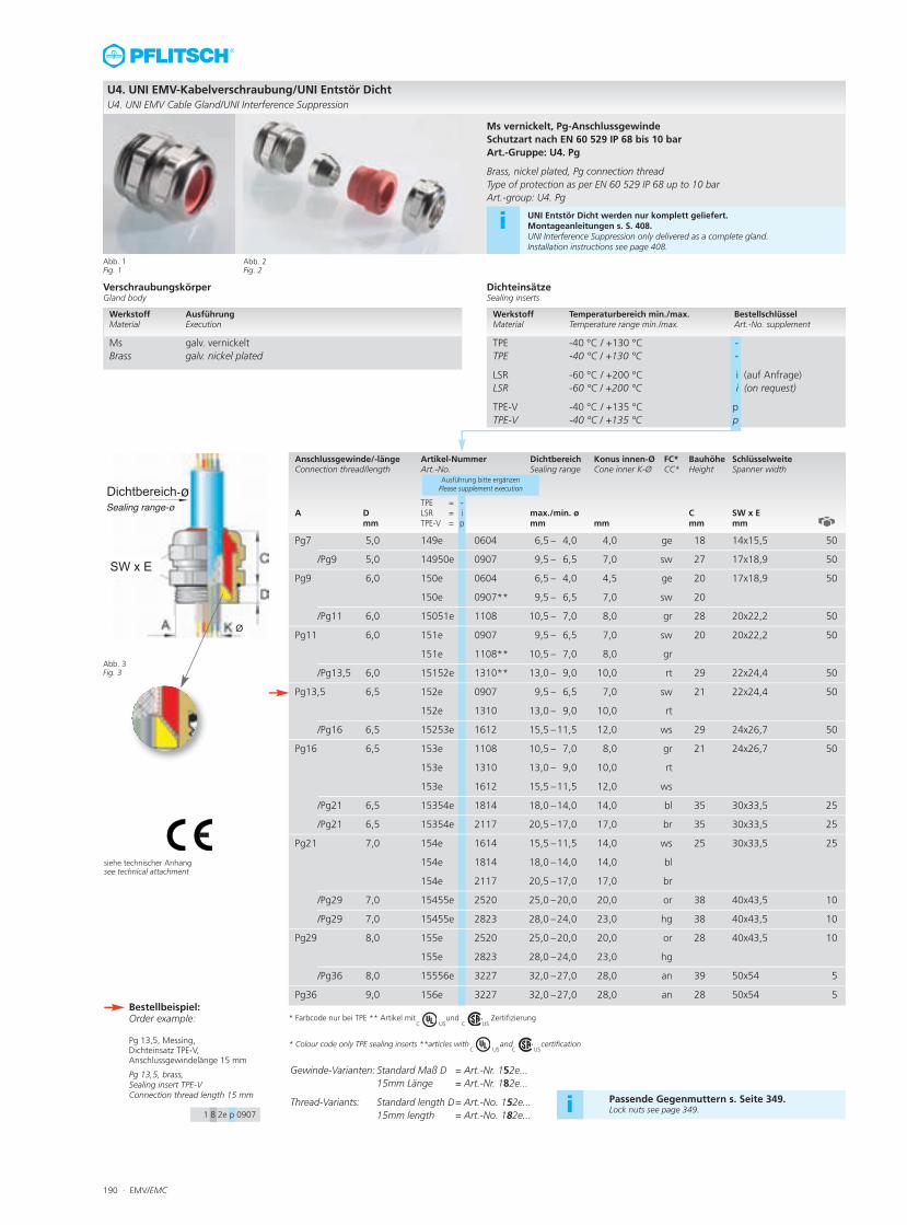
Anschlussgewinde/-länge Artikel-Nummer Dichtbereich Konus innen-Ø FC* Bauhöhe SchlüsselweiteConnection thread/length Art.-No. Sealing range Cone inner K-Ø CC* Height Spanner width
TPE = -A D LSR = i max./min. ø C SW x E
mm TPE-V = p mm mm mm mm
Ausführung bitte ergänzenPlease supplement execution
Pg7 5,0 149e 0604 6,5 – 4,0 4,0 ge 18 14x15,5 50
/Pg9 5,0 14950e 0907 9,5 – 6,5 7,0 sw 27 17x18,9 50
Pg9 6,0 150e 0604 6,5 – 4,0 4,5 ge 20 17x18,9 50
150e 0907** 9,5 – 6,5 7,0 sw 20
/Pg11 6,0 15051e 1108 10,5 – 7,0 8,0 gr 28 20x22,2 50
Pg11 6,0 151e 0907 9,5 – 6,5 7,0 sw 20 20x22,2 50
151e 1108** 10,5 – 7,0 8,0 gr
/Pg13,5 6,0 15152e 1310** 13,0 – 9,0 10,0 rt 29 22x24,4 50
Pg13,5 6,5 152e 0907 9,5 – 6,5 7,0 sw 21 22x24,4 50
152e 1310 13,0 – 9,0 10,0 rt
/Pg16 6,5 15253e 1612 15,5 –11,5 12,0 ws 29 24x26,7 50
Pg16 6,5 153e 1108 10,5 – 7,0 8,0 gr 21 24x26,7 50
153e 1310 13,0 – 9,0 10,0 rt
153e 1612 15,5 –11,5 12,0 ws
/Pg21 6,5 15354e 1814 18,0 –14,0 14,0 bl 35 30x33,5 25
/Pg21 6,5 15354e 2117 20,5 –17,0 17,0 br 35 30x33,5 25
Pg21 7,0 154e 1614 15,5 –11,5 14,0 ws 25 30x33,5 25
154e 1814 18,0 –14,0 14,0 bl
154e 2117 20,5 –17,0 17,0 br
/Pg29 7,0 15455e 2520 25,0 –20,0 20,0 or 38 40x43,5 10
/Pg29 7,0 15455e 2823 28,0 –24,0 23,0 hg 38 40x43,5 10
Pg29 8,0 155e 2520 25,0 –20,0 20,0 or 28 40x43,5 10
155e 2823 28,0 –24,0 23,0 hg
/Pg36 8,0 15556e 3227 32,0 –27,0 28,0 an 39 50x54 5
Pg36 9,0 156e 3227 32,0 –27,0 28,0 an 28 50x54 5
U4. UNI EMV-Kabelverschraubung/UNI Entstör DichtU4. UNI EMV Cable Gland/UNI Interference Suppression
Abb. 1Fig. 1
Abb. 2Fig. 2
Abb. 3 Fig. 3
siehe technischer Anhangsee technical attachment
Passende Gegenmuttern s. Seite 349.Lock nuts see page 349.i
VerschraubungskörperGland body
DichteinsätzeSealing inserts
Werkstoff AusführungMaterial Execution
Ms galv. vernickelt Brass galv. nickel plated
Werkstoff Temperaturbereich min./max. BestellschlüsselMaterial Temperature range min./max. Art.-No. supplement
TPE -40 °C / +130 °C -TPE -40 °C / +130 °C -
LSR -60 °C / +200 °C i (auf Anfrage)LSR -60 °C / +200 °C i (on request)
TPE-V -40 °C / +135 °C pTPE-V -40 °C / +135 °C p
i UNI Entstör Dicht werden nur komplett geliefert. Montageanleitungen s. S. 408.UNI Interference Suppression only delivered as a complete gland. Installation instructions see page 408.
Gewinde-Varianten: Standard Maß D = Art.-Nr. 152e...15mm Länge = Art.-Nr. 182e...
Thread-Variants: Standard length D= Art.-No. 152e...15mm length = Art.-No. 182e...
* Farbcode nur bei TPE ** Artikel mit und Zertifizierung
* Colour code only TPE sealing inserts **articles with and certification
C US C US
C US C US
Ms vernickelt, Pg-AnschlussgewindeSchutzart nach EN 60 529 IP 68 bis 10 bar Art.-Gruppe: U4. Pg
Brass, nickel plated, Pg connection threadType of protection as per EN 60 529 IP 68 up to 10 bar Art.-group: U4. Pg
Bestellbeispiel:Order example:
Pg 13,5, Messing, Dichteinsatz TPE-V, Anschlussgewindelänge 15 mm
Pg 13,5, brass, Sealing insert TPE-VConnection thread length 15 mm
1 8 2e p 0907
EMV/EMC · 191
Anschlussgewinde/-länge Artikel-Nummer Dichtbereich Konus innen-Ø FC* Bauhöhe SchlüsselweiteConnection thread/length Art.-No. Sealing range Cone inner-Ø CC* Height Spanner width
A D TPE = - max./min. ø C SW x E
mm TPE-V = p mm mm mm mm
Ausführung bitte ergänzenPlease supplement execution
Pg7 5,0 149e z0604 6,5 – 4,0 4,0 ge 18 14x15,5 50
/Pg9 5,0 14950e z0907 9,0 – 5,5 7,0 sw 27 17x18,9 50
Pg9 6,0 150e z0604 6,5 – 4,0 4,5 ge 20 17x18,9 50
150e z0907 9,0 – 5,5 7,0 sw 20 17x18,9 50
/Pg11 6,0 15051e z1108 10,0 – 6,0 8,0 gr 28 20x22,2 50
Pg11 6,0 151e z0907 9,0 – 5,5 7,0 sw 20 20x22,2 50
151e z1108 10,0 – 6,0 8,0 gr 20 20x22,2 50
/Pg13,5 6,0 15152e z1310 12,0 – 8,0 10,0 rt 29 22x24,4 50
Pg13,5 6,5 152e z0907 9,0 – 5,5 7,0 sw 21 22x24,4 50
152e z1310 12,0 – 8,0 10,0 rt 21 22x24,4 50
/Pg16 6,5 15253e z1612 15,0 –12,0 12,0 ws 29 24x26,7 50
Pg16 6,5 153e z1108 10,5 – 7,0 8,0 gu 21 24x26,7 50
153e z1310 13,0 – 9,0 10,0 rt 21 24x26,7 50
153e z1612 15,5 –11,5 12,0 ws 21 24x26,7 50
/Pg21 6,5 15354e z1814 17,0 –14,0 14,0 bl 35 30x33,5 25
15354e z2117 20,0 –16,0 17,0 br 35 30x33,5 25
Pg21 7,0 154e z1814 17,0 –14,0 14,0 bl 25 30x33,5 25
154e z2117 20,0 –16,0 17,0 br 25 30x33,5 25
/Pg29 7,0 15455e z2520 24,0 –20,0 20,0 or 38 40x43,5 10
15455e z2823 27,0 –23,0 23,0 hg 38 40x43,5 10
Pg29 8,0 155e z2520 24,0 –20,0 20,0 or 28 40x43,5 10
155e z2823 27,0 –23,0 23,0 hg 28 40x43,5 10
/Pg36 8,0 15556e z3227 32,0 –27,0 28,0 an 29 50x54 5
Pg36 9,0 156e z3227 32,0 –27,0 28,0 an 28 50x54 5
U4. UNI EMV-Kabelverschraubung/UNI Entstör DichtU4. UNI EMV Cable Gland/UNI Interference Suppression Dicht
Abb. 1Fig. 1
Abb. 2Fig. 2
Abb. 3 Fig. 3
siehe technischer Anhangsee technical attachment
Passende Gegenmuttern s. Seite 349.Lock nuts see page 349.i
VerschraubungskörperGland body
DichteinsätzeSealing inserts
Werkstoff Ausführung Material Execution
Ms galv. vernickelt Brass galv. nickel plated
Werkstoff Temperaturbereich min./max. BestellschlüsselMaterial Temperature range min./max. Art.-No. supplement
TPE* -20 °C / +100 °C -TPE* -20 °C / +100 °C -
TPE-V* -20 °C / +100 °C pTPE-V* -20 °C / +100 °C p
i UNI Entstör Dicht werden nur komplett geliefert. Montageanleitungen s. S. 408.UNI Interference Suppression only delivered as a complete gland. Installation instructions see page 408.
Gewinde-Varianten: Standard Maß D = Art.-Nr. 152...15mm Länge = Art.-Nr. 182...
Thread-Variants: Standard length D= Art.-No. 152...15mm length = Art.-No. 182...
Ms vernickelt, mit erhöhter Zugentlastung, Pg-AnschlussgewindeSchutzart nach EN 60 529 IP 54 Art.-Gruppe: U4. Pg Zug
Brass, nickel plated, with increased strain relief, Pg connection threadType of protection as per EN 60 529 IP 54 Art.-group: U4. Pg Zug
* Mit integriertem Klemmkörper aus PA* with integrated clamp body made of PA
Bestellbeispiel:Order example:
Pg 13,5, Messing, Dichteinsatz TPE-V, Anschlussgewindelänge 15 mm
Pg 13,5, brass, Sealing insert TPE-VConnection thread length 15 mm
1 8 2e p z0907
192 · EMV/EMC
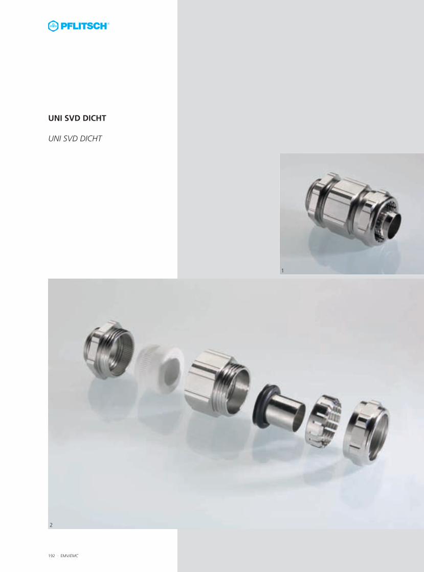
UNI SVD DICHT
UNI SVD DICHT
1
2
EMV/EMC · 193
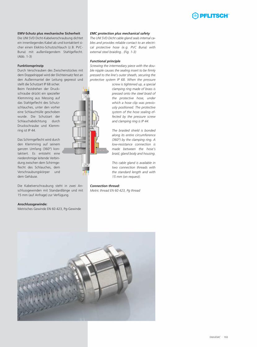
EMC protection plus mechanical safetyThe UNI SVD Dicht cable gland seals internal ca-bles and provides reliable contact to an electri-cal protective hose (e.g. PVC Buna) withexternal steel braiding.. (Fig. 1-3)
Functional principleScrewing the intermediary piece with the dou-ble nipple causes the sealing insert to be firmlypressed to the line’s outer sheath, securing theprotective system IP 68. When the pressure
screw is tightened up, a specialclamping ring made of brass ispressed onto the steel braid ofthe protective hose, underwhich a hose clip was previo-usly positioned. The protectivesystem of the hose sealing ef-fected by the pressure screwand clamping ring is IP 44.
The braided shield is bondedalong its entire circumference(360°) by the clamping ring. Alow-resistance connection ismade between the hose’sbraid, gland body and housing.
This cable gland is available intwo connection threads withthe standard length and with15 mm (on request).
Connection thread:Metric thread EN 60 423, Pg thread
EMV-Schutz plus mechanische SicherheitDie UNI SVD Dicht-Kabelverschraubung dichtetein innenliegendes Kabel ab und kontaktiert si-cher einen Elektro-Schutzschlauch (z.B. PVC-Buna) mit außenliegendem Stahlgeflecht. (Abb. 1-3)
FunktionsprinzipDurch Verschrauben des Zwischenstückes mitdem Doppelnippel wird der Dichteinsatz fest anden Außenmantel der Leitung gepresst undstellt die Schutzart IP 68 sicher.Beim Festdrehen der Druck-schraube drückt ein speziellerKlemmring aus Messing aufdas Stahlgeflecht des Schutz-schlauches, unter den vorhereine Schlauchtülle geschobenwurde. Die Schutzart derSchlauchabdichtung durchDruckschraube und Klemm-ring ist IP 44.
Das Schirmgeflecht wird durchden Klemmring auf seinemganzen Umfang (360°) kon-taktiert. Es entsteht eine niederohmige leitende Verbin-dung zwischen dem Schirmge-flecht des Schlauches, demVerschraubungskörper unddem Gehäuse.
Die Kabelverschraubung steht in zwei An-schlussgewinden mit Standardlänge und mit15 mm (auf Anfrage) zur Verfügung.
Anschlussgewinde:Metrisches Gewinde EN 60 423, Pg-Gewinde
3
194 · EMV/EMC
Abb. 1Fig. 1
Abb. 1Fig. 1
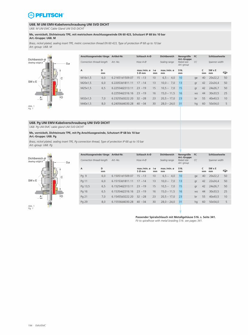
U68. M UNI EMV-Kabelverschraubung UNI SVD DICHTU68. M UNI EMC Cable Gland UNI SVD DICHT
Anschlussgewinde/-länge Artikel-Nr. Schlauch A-Ø Dichtbereich Nenngröße FC Schlüsselweite Art.-Gruppe Connection thread/-length Art.-No. Hose A-Ø Sealing range Rated size CC Spanner width Art.-group A D max./min. ø i-ø max./min. ø S16. C SW x E
mm S Ø mm mm mm mm mm mm
Anschlussgewinde/-länge Artikel-Nr. Schlauch A-Ø Dichtbereich Nenngröße FC Schlüsselweite Art.-Gruppe Connection thread/-length Art.-No. Hose A-Ø Sealing range Rated size CC Spanner width Art.-group A D max./min. ø i-ø max./min. ø S16. C SW x E
mm S Ø mm mm mm mm mm mm
Ms, vernickelt, Dichteinsatz TPE, mit metrischem Anschlussgewinde EN 60 423, Schutzart IP 68 bis 10 barArt.-Gruppe: U68. M
Brass, nickel plated, sealing insert TPE, metric connection thread EN 60 423, Type of protection IP 68 up to 10 bar Art.-group: U68. M
U68. Pg UNI EMV-Kabelverschraubung UNI SVD DICHTU68. Pg UNI EMC cable gland UNI SVD DICHT
Ms, vernickelt, Dichteinsatz TPE, mit Pg Anschlussgewinde, Schutzart IP 68 bis 10 barArt.-Gruppe: U68. Pg
Brass, nickel plated, sealing insert TPE, Pg connection thread, Type of protection IP 68 up to 10 bar Art.-group: U68. Pg
M16x1,5 �6,0 6.21651d1509.07 15 –13 �10 6,5 – 4,0 �10 ge �40 20x22,2 �50
M20x1,5 6,0 6.22053d1811.11 17 –14 13 10,0 – 7,0 13 gr 42 22x24,4 50
M25x1,5 6,5 6.22554d2313.11 23 –19 15 10,5 – 7,0 15 gr 42 24x26,7 50
6.22554d2316.16 23 –19 16 15,0 – 11,5 16 ws 44 30x33,5 25
M32x1,5 7,0 6.23255d3222.20 32 –28 23 20,5 – 17,0 23 br 55 40x43,5 10
M40x1,5 8,0 6.24056d4030.28 40 –34 30 28,0 – 24,0 31 hg 60 50x54,0 5
Pg 9 �6,0 6.15051d1509.07 15 –13 �10 6,5 – 4,0 �10 ge �40 20x22,2 �50
Pg 11 6,0 6.15153d1811.11 17 –14 13 10,0 – 7,0 13 gr 42 22x24,4 50
Pg 13,5 6,5 6.15254d2313.11 23 –19 15 10,5 – 7,0 15 gr 42 24x26,7 50
Pg 16 6,5 6.15354d2316.16 23 –19 16 15,0 – 11,5 16 ws 44 30x33,5 25
Pg 21 7,0 6.15455d3222.20 32 –28 23 20,5 – 17,0 23 br 55 40x43,5 10
Pg 29 8,0 6.15556d4030.28 40 –34 30 28,0 – 24,0 31 hg 60 50x54,0 5
Passender Spiralschlauch mit Metallgehäuse S16. s. Seite 341.Fit to spiralhose with metal braiding S16. see pages 341.
EMV/EMC · 195
196 · EMV/EMC
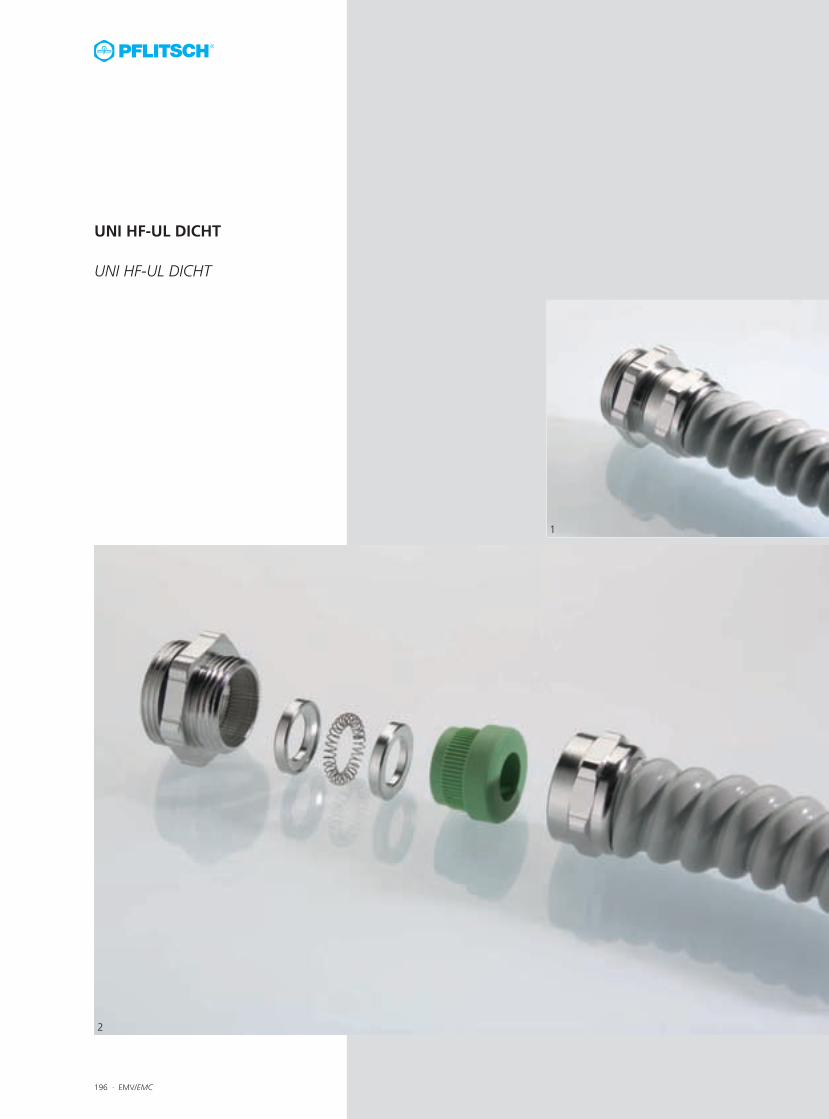
UNI HF-UL DICHT
UNI HF-UL DICHT
1
2
EMV/EMC · 197
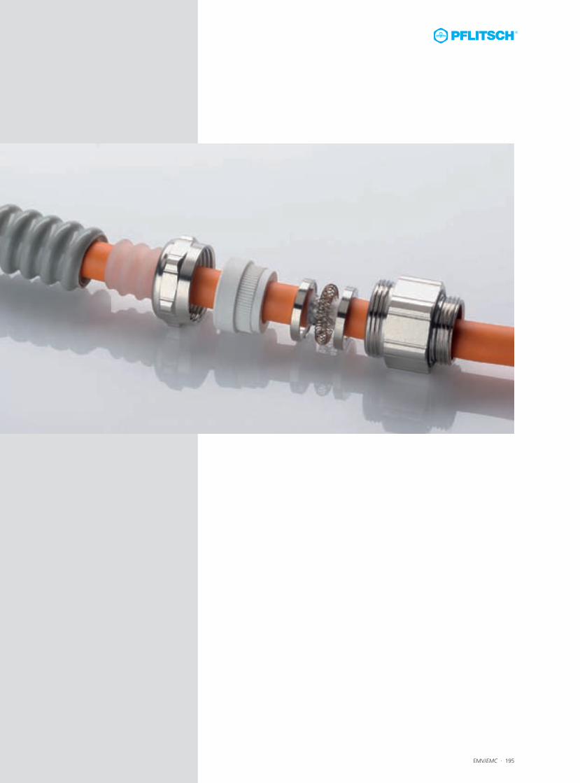
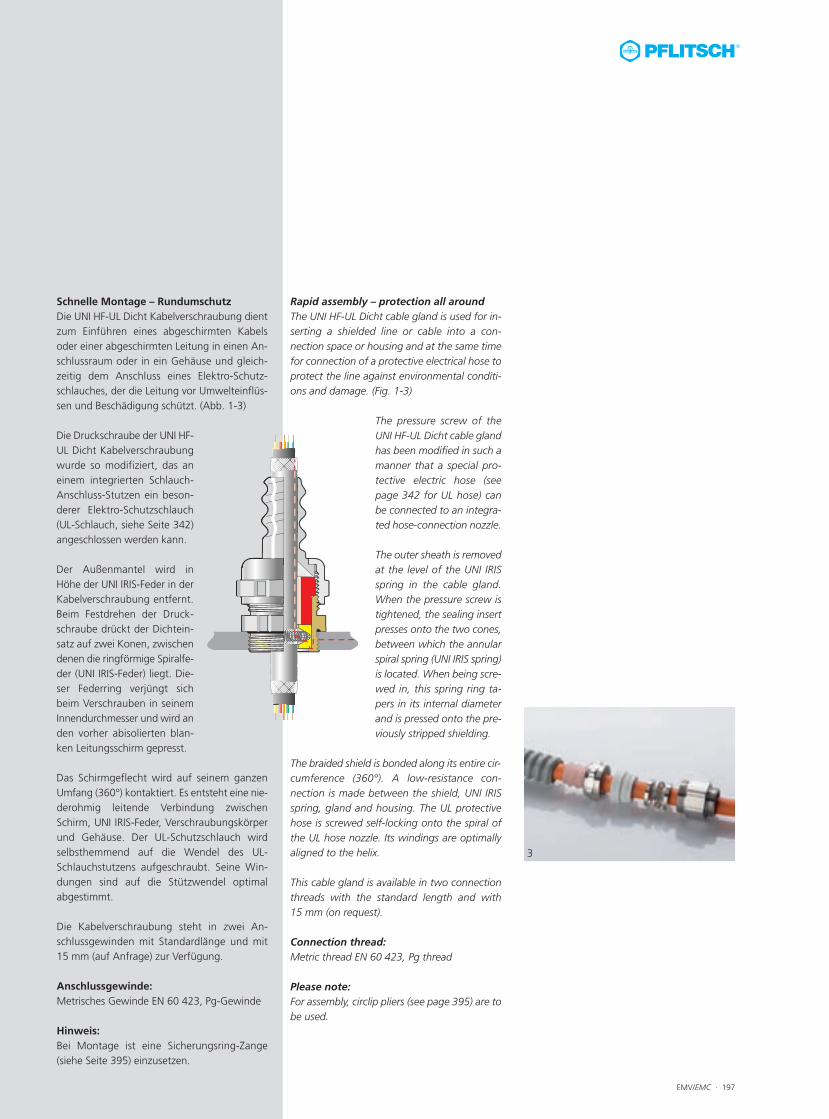
Rapid assembly – protection all aroundThe UNI HF-UL Dicht cable gland is used for in-serting a shielded line or cable into a con-nection space or housing and at the same timefor connection of a protective electrical hose toprotect the line against environmental conditi-ons and damage. (Fig. 1-3)
The pressure screw of theUNI HF-UL Dicht cable glandhas been modified in such amanner that a special pro-tective electric hose (seepage 342 for UL hose) canbe connected to an integra-ted hose-connection nozzle.
The outer sheath is removedat the level of the UNI IRISspring in the cable gland.When the pressure screw istightened, the sealing insertpresses onto the two cones,between which the annularspiral spring (UNI IRIS spring)is located. When being scre-wed in, this spring ring ta-pers in its internal diameterand is pressed onto the pre-viously stripped shielding.
The braided shield is bonded along its entire cir-cumference (360°). A low-resistance con-nection is made between the shield, UNI IRISspring, gland and housing. The UL protectivehose is screwed self-locking onto the spiral ofthe UL hose nozzle. Its windings are optimallyaligned to the helix.
This cable gland is available in two connectionthreads with the standard length and with15 mm (on request).
Connection thread:Metric thread EN 60 423, Pg thread
Please note:For assembly, circlip pliers (see page 395) are tobe used.
Schnelle Montage – RundumschutzDie UNI HF-UL Dicht Kabelverschraubung dientzum Einführen eines abgeschirmten Kabelsoder einer abgeschirmten Leitung in einen An-schlussraum oder in ein Gehäuse und gleich-zeitig dem Anschluss eines Elektro-Schutz -schlauches, der die Leitung vor Umwelteinflüs-sen und Beschädigung schützt. (Abb. 1-3)
Die Druckschraube der UNI HF-UL Dicht Kabelverschraubungwurde so modifiziert, das aneinem integrierten Schlauch-Anschluss-Stutzen ein beson-derer Elektro-Schutzschlauch(UL-Schlauch, siehe Seite 342)angeschlossen werden kann.
Der Außenmantel wird inHöhe der UNI IRIS-Feder in derKabelverschraubung entfernt.Beim Festdrehen der Druck-schraube drückt der Dichtein-satz auf zwei Konen, zwischendenen die ringförmige Spiralfe-der (UNI IRIS-Feder) liegt. Die-ser Federring verjüngt sichbeim Verschrauben in seinemInnendurchmesser und wird anden vorher abisolierten blan-ken Leitungsschirm gepresst.
Das Schirmgeflecht wird auf seinem ganzenUmfang (360°) kontaktiert. Es entsteht eine nie-derohmig leitende Verbindung zwischenSchirm, UNI IRIS-Feder, Verschraubungskörperund Gehäuse. Der UL-Schutzschlauch wirdselbsthemmend auf die Wendel des UL-Schlauchstutzens aufgeschraubt. Seine Win-dungen sind auf die Stützwendel optimalabgestimmt.
Die Kabelverschraubung steht in zwei An-schlussgewinden mit Standardlänge und mit15 mm (auf Anfrage) zur Verfügung.
Anschlussgewinde:Metrisches Gewinde EN 60 423, Pg-Gewinde
Hinweis: Bei Montage ist eine Sicherungsring-Zange(siehe Seite 395) einzusetzen.
3
198 · EMV/EMC
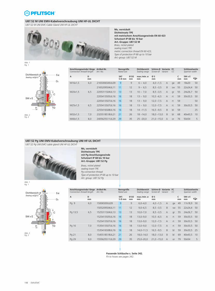
U87.52 M UNI EMV-Kabelverschraubung UNI HF-UL DICHTU87.52 M UNI EMC-Cable Gland UNI HF-UL DICHT
Anschlussgewinde/-länge Artikel-Nr. Nenngröße Dichtbereich Schirm-Ø Variante FC SchlüsselweiteConnection thread/-length Art.-No. Rated size Sealing range Screen-Ø Variant CC Spanner width A D S47 Ø D2 max./min. ø Ø S C SW x E
mm S Ø mm mm mm mm mm mm
Ms, vernickeltDichteinsatz TPEmit metrischem Anschlussgewinde EN 60 423Schutzart IP 68 bis 10 barArt.-Gruppe: U87.52 MBrass, nickel platedsealing insert TPEmetric connection thread EN 60 423, Type of protection IP 68 up to 10 bar Art.-group: U87.52 M
Passende Schläuche s. Seite 342.Fit to hoses see pages 342.
M16x1,5 �6,0 2165006S00UL09 �9 �9 6 – 4,0 4,0 –1,5 �A ge 49 18x20 �50
2165209S04UL11 11 12 9 – 6,5 8,5 –3,5 B sw 55 22x24,4 50
M20x1,5 6,5 2205311S04UL13 13 13 10 – 7,0 8,5 –3,5 A gr 55 24x26,7 50
2205413S05UL16 16 18 13 – 9,0 10,5 –6,5 A rt 59 30x33,5 50
2205413S07UL16 16 18 13 – 9,0 12,0 –7,5 A rt 59 50
M25x1,5 6,5 2255413S07UL16 16 18 13 – 9,0 12,0 –7,5 A rt 59 30x33,5 50
2255416S08UL16 16 18 14 –11,5 16,5 –9,5 B bl 59 25
M32x1,5 7,0 2325518S18UL21 21 26 18 –14,0 18,0 –13,0 B bl 68 40x43,5 10
M40x1,5 8,0 2405625S11UL29 29 35 25 –20,0 21,0 –15,0 A or 76 50x54 5
U87.52 Pg UNI EMV-Kabelverschraubung UNI HF-UL DICHTU87.52 Pg UNI EMC-cable gland UNI HF-UL DICHT
Anschlussgewinde/-länge Artikel-Nr. Nenngröße Dichtbereich Schirm-Ø Variante FC SchlüsselweiteConnection thread/-length Art.-No. Rated size Sealing range Screen-Ø Variant CC Spanner width A D S47. Ø D2 max./min. ø Ø S C SW x E
mm S Ø mm mm mm mm mm mm
Ms, vernickeltDichteinsatz TPEmit Pg-AnschlussgewindeSchutzart IP 68 bis 10 barArt.-Gruppe: U87.52 Pg
Brass, nickel platedsealing insert TPEPg connection threadType of protection IP 68 up to 10 bar Art. group: U87.52 Pg
Pg 9 �6,0 15006S00UL09 �9 �9 � 6,0–4,0 � 4,0 –1,5 �A ge 49 17x18,9 �50
1505209S04UL11 11 12 9,0–6,5 8,5 –3,5 B sw 55 22x24,4 50
Pg 13,5 6,5 1525311S04UL13 13 13 10,0–7,0 8,5 –3,5 A gr 55 24x26,7 50
1525413S05UL16 16 18 13,0–9,0 10,5 –6,5 A rt 59 30x33,5 50
1525413S07UL16 16 18 13,0–9,0 12,0 –7,5 A rt 59 30x33,5 50
Pg 16 7,0 1535413S07UL16 16 18 13,0–9,0 12,0 –7,5 A rt 59 30x33,5 50
1535416S08UL16 16 18 14,0–11,5 16,5 –9,5 B bl 59 30x33,5 25
Pg 21 8,0 1545518S18UL21 21 26 18,0–14,0 18,0 –13,0 B bl 69 40x43,5 10
Pg 29 9,0 1555625S11UL29 29 35 25,0–20,0 21,0 –15,0 A or 79 50x54 5
Abb. 2Fig. 2
Abb. 2Fig. 2
Abb. 1Fig. 1
Abb. 1Fig. 1
EMV/EMC · 199
IP69K
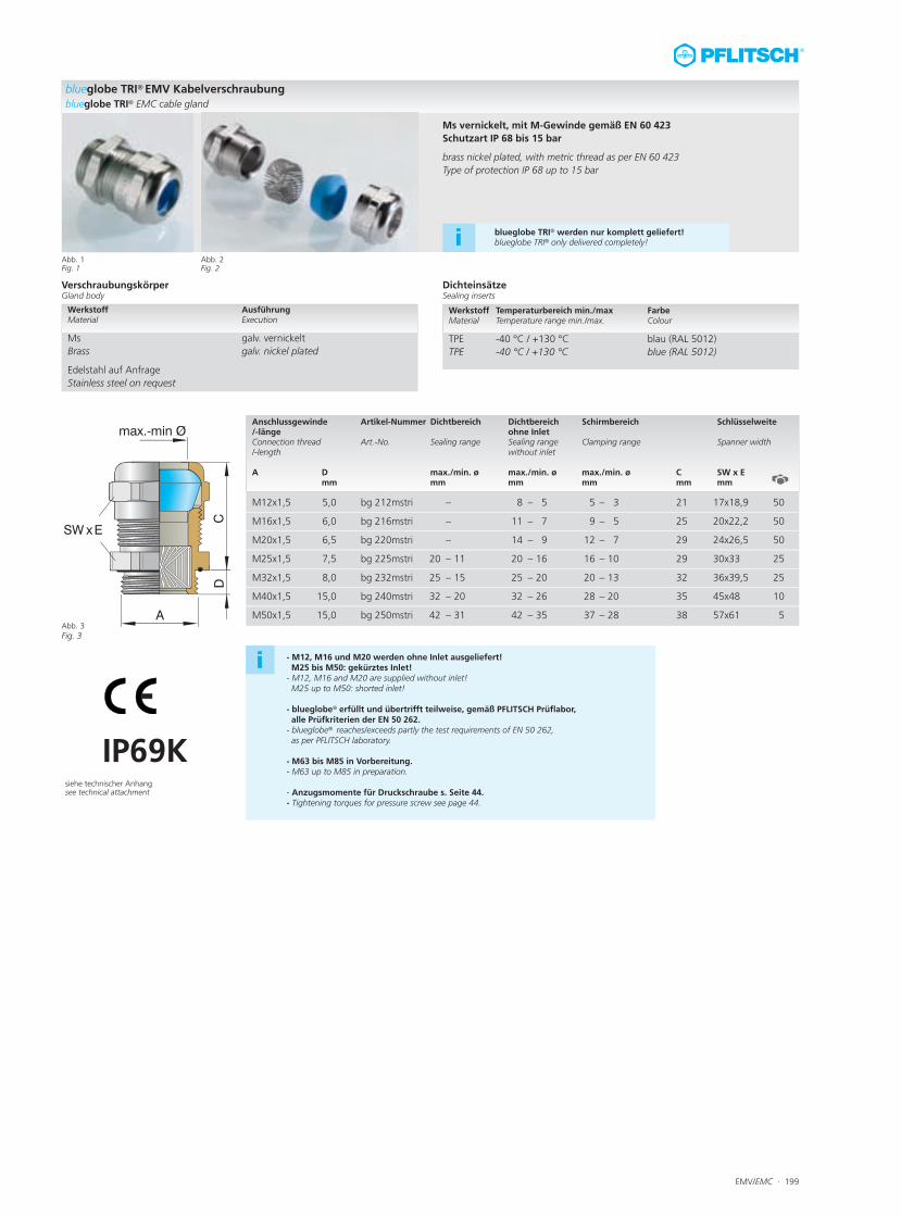
blueglobe TRI® EMV Kabelverschraubungblueglobe TRI® EMC cable gland
Ms vernickelt, mit M-Gewinde gemäß EN 60 423Schutzart IP 68 bis 15 bar
brass nickel plated, with metric thread as per EN 60 423Type of protection IP 68 up to 15 bar
VerschraubungskörperGland body
DichteinsätzeSealing inserts
Anschlussgewinde Artikel-Nummer Dichtbereich Dichtbereich Schirmbereich Schlüsselweite/-länge ohne Inlet Connection thread Art.-No. Sealing range Sealing range Clamping range Spanner width/-length without inlet A D max./min. ø max./min. ø max./min. ø C SW x E mm mm mm mm mm mm
Werkstoff Temperaturbereich min./max Farbe Material Temperature range min./max. Colour
TPE -40 °C / +130 °C blau (RAL 5012)TPE -40 °C / +130 °C blue (RAL 5012)
M12x1,5 5,0 bg 212mstri – 8 – 5 5 – 3 21 17x18,9 50
M16x1,5 6,0 bg 216mstri – 11 – 7 9 – 5 25 20x22,2 50
M20x1,5 �6,5 bg 220mstri �– 14 – 9 �12 – 7 29 24x26,5 50
M25x1,5 7,5 bg 225mstri 20 – 11 20 – 16 16 – 10 29 30x33 25
M32x1,5 8,0 bg 232mstri 25 – 15 25 – 20 20 – 13 32 36x39,5 25
M40x1,5 15,0 bg 240mstri 32 – 20 32 – 26 28 – 20 35 45x48 10
M50x1,5 15,0 bg 250mstri 42 – 31 42 – 35 37 – 28 38 57x61 5
Werkstoff Ausführung Material Execution
Ms galv. vernickelt Brass galv. nickel plated
Edelstahl auf Anfrage Stainless steel on request
blueglobe TRI® werden nur komplett geliefert!blueglobe TRI® only delivered completely!i
siehe technischer Anhangsee technical attachment
Abb. 3 Fig. 3
Abb. 1Fig. 1
Abb. 2Fig. 2
i - M12, M16 und M20 werden ohne Inlet ausgeliefert! M25 bis M50: gekürztes Inlet!
- M12, M16 and M20 are supplied without inlet!M25 up to M50: shorted inlet!
- blueglobe® erfüllt und übertrifft teilweise, gemäß PFLITSCH Prüflabor, alle Prüfkriterien der EN 50 262.
- blueglobe® reaches/exceeds partly the test requirements of EN 50 262, as per PFLITSCH laboratory.
- M63 bis M85 in Vorbereitung. - M63 up to M85 in preparation.
- Anzugsmomente für Druckschraube s. Seite 44.- Tightening torques for pressure screw see page 44.
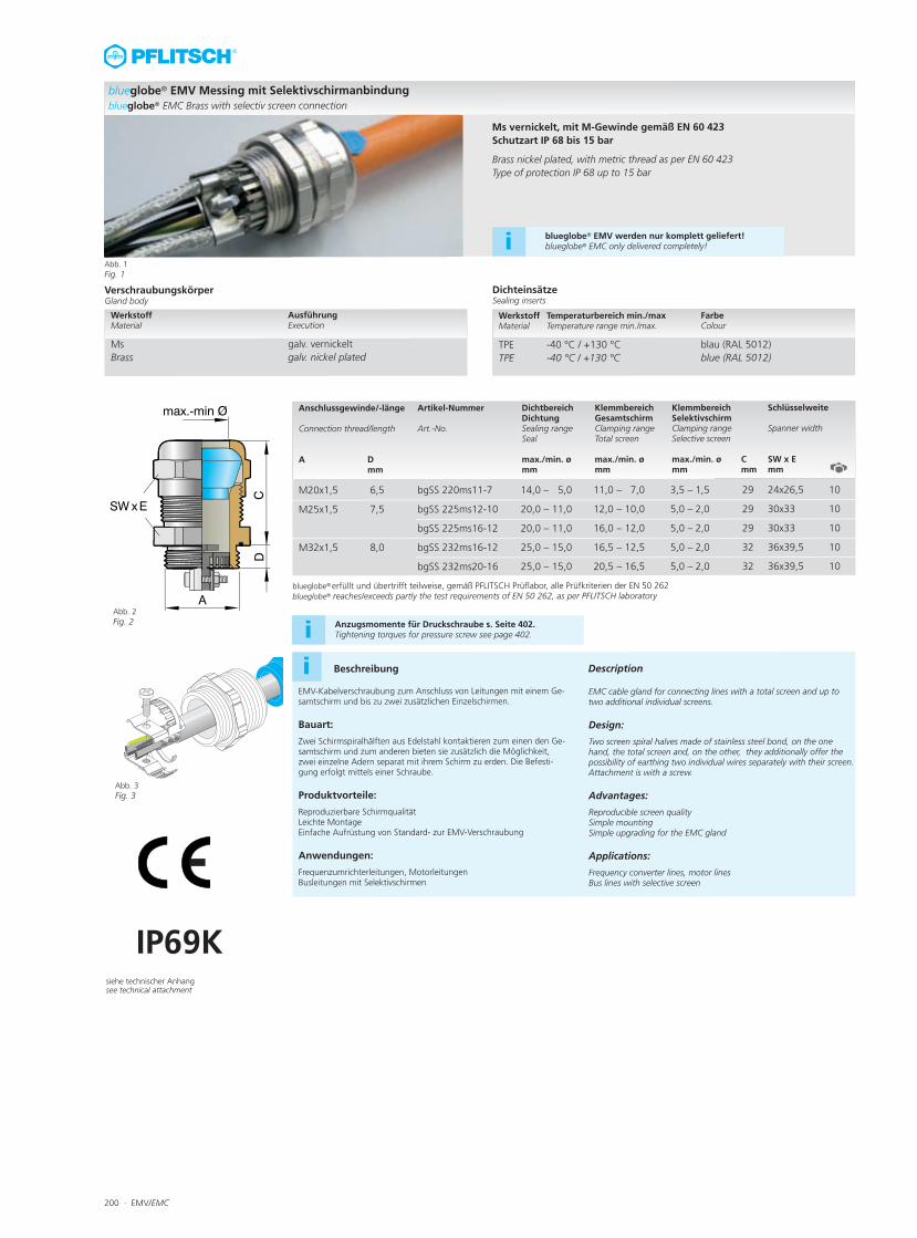
200 · EMV/EMC
Abb. 2 Fig. 2
Abb. 3Fig. 3
blueglobe® EMV Messing mit Selektivschirmanbindungblueglobe® EMC Brass with selectiv screen connection
Ms vernickelt, mit M-Gewinde gemäß EN 60 423Schutzart IP 68 bis 15 bar
Brass nickel plated, with metric thread as per EN 60 423Type of protection IP 68 up to 15 bar
VerschraubungskörperGland body
DichteinsätzeSealing inserts
Anschlussgewinde/-länge Artikel-Nummer Dichtbereich Klemmbereich Klemmbereich Schlüsselweite Dichtung Gesamtschirm SelektivschirmConnection thread/length Art.-No. Sealing range Clamping range Clamping range Spanner width Seal Total screen Selective screen A D max./min. ø max./min. ø max./min. ø C SW x E mm mm mm mm mm mm
Werkstoff Temperaturbereich min./max Farbe Material Temperature range min./max. Colour
TPE -40 °C / +130 °C blau (RAL 5012)TPE -40 °C / +130 °C blue (RAL 5012)
M20x1,5 �6,5 bgSS 220ms11-7 �14,0 – 5,0 �11,0 – 7,0 3,5 – 1,5 29 24x26,5 �10
M25x1,5 7,5 bgSS 225ms12-10 20,0 – 11,0 12,0 – 10,0 5,0 – 2,0 29 30x33 10
bgSS 225ms16-12 20,0 – 11,0 16,0 – 12,0 5,0 – 2,0 29 30x33 10
M32x1,5 8,0 bgSS 232ms16-12 25,0 – 15,0 16,5 – 12,5 5,0 – 2,0 32 36x39,5 10
bgSS 232ms20-16 25,0 – 15,0 20,5 – 16,5 5,0 – 2,0 32 36x39,5 10
Werkstoff Ausführung Material Execution
Ms galv. vernickelt Brass galv. nickel plated
Abb. 1Fig. 1
i Beschreibung Description
EMV-Kabelverschraubung zum Anschluss von Leitungen mit einem Ge-samtschirm und bis zu zwei zusätzlichen Einzelschirmen.
Bauart:
Zwei Schirmspiralhälften aus Edelstahl kontaktieren zum einen den Ge-samtschirm und zum anderen bieten sie zusätzlich die Möglichkeit,zwei einzelne Adern separat mit ihrem Schirm zu erden. Die Befesti-gung erfolgt mittels einer Schraube.
Produktvorteile:
Reproduzierbare SchirmqualitätLeichte MontageEinfache Aufrüstung von Standard- zur EMV-Verschraubung
Anwendungen:
Frequenzumrichterleitungen, MotorleitungenBusleitungen mit Selektivschirmen
EMC cable gland for connecting lines with a total screen and up totwo additional individual screens.
Design:
Two screen spiral halves made of stainless steel bond, on the onehand, the total screen and, on the other, they additionally offer thepossibility of earthing two individual wires separately with their screen.Attachment is with a screw.
Advantages:
Reproducible screen qualitySimple mountingSimple upgrading for the EMC gland
Applications:
Frequency converter lines, motor linesBus lines with selective screen
IP69Ksiehe technischer Anhangsee technical attachment
blueglobe® EMV werden nur komplett geliefert!blueglobe® EMC only delivered completely!i
blueglobe® erfüllt und übertrifft teilweise, gemäß PFLITSCH Prüflabor, alle Prüfkriterien der EN 50 262blueglobe® reaches/exceeds partly the test requirements of EN 50 262, as per PFLITSCH laboratory
Anzugsmomente für Druckschraube s. Seite 402.Tightening torques for pressure screw see page 402.i
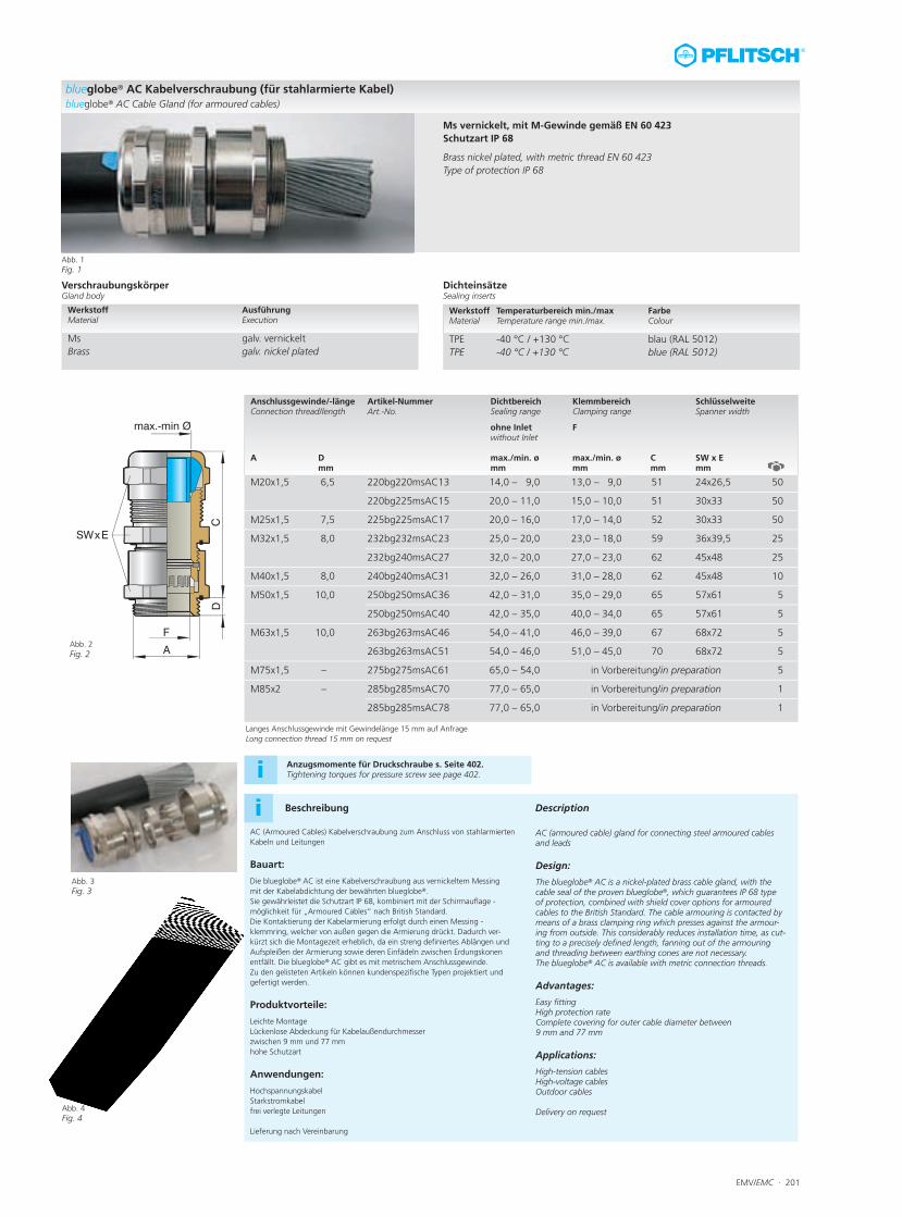
EMV/EMC · 201
Anzugsmomente für Druckschraube s. Seite 402.Tightening torques for pressure screw see page 402.i
Abb. 2 Fig. 2
Abb. 3Fig. 3
blueglobe® AC Kabelverschraubung (für stahlarmierte Kabel)blueglobe® AC Cable Gland (for armoured cables)
Ms vernickelt, mit M-Gewinde gemäß EN 60 423Schutzart IP 68
Brass nickel plated, with metric thread EN 60 423Type of protection IP 68
VerschraubungskörperGland body
DichteinsätzeSealing inserts
Anschlussgewinde/-länge Artikel-Nummer Dichtbereich Klemmbereich SchlüsselweiteConnection thread/length Art.-No. Sealing range Clamping range Spanner width
ohne Inlet F without Inlet A D max./min. ø max./min. ø C SW x E mm mm mm mm mm
Werkstoff Temperaturbereich min./max Farbe Material Temperature range min./max. Colour
TPE -40 °C / +130 °C blau (RAL 5012)TPE -40 °C / +130 °C blue (RAL 5012)
M20x1,5 �6,5 220bg220msAC13 14,0 – 9,0 13,0 – 9,0 �51 24x26,5 �50
220bg225msAC15 20,0 – 11,0 15,0 – 10,0 51 30x33 50
M25x1,5 7,5 225bg225msAC17 20,0 – 16,0 17,0 – 14,0 52 30x33 50
M32x1,5 8,0 232bg232msAC23 25,0 – 20,0 23,0 – 18,0 59 36x39,5 25
232bg240msAC27 32,0 – 20,0 27,0 – 23,0 62 45x48 25
M40x1,5 8,0 240bg240msAC31 32,0 – 26,0 31,0 – 28,0 62 45x48 10
M50x1,5 10,0 250bg250msAC36 42,0 – 31,0 35,0 – 29,0 65 57x61 5
250bg250msAC40 42,0 – 35,0 40,0 – 34,0 65 57x61 5
M63x1,5 10,0 263bg263msAC46 54,0 – 41,0 46,0 – 39,0 67 68x72 5
263bg263msAC51 54,0 – 46,0 51,0 – 45,0 70 68x72 5
M75x1,5 – 275bg275msAC61 65,0 – 54,0 in Vorbereitung/in preparation 5
M85x2 – 285bg285msAC70 77,0 – 65,0 in Vorbereitung/in preparation 1
285bg285msAC78 77,0 – 65,0 in Vorbereitung/in preparation 1
Werkstoff Ausführung Material Execution
Ms galv. vernickelt Brass galv. nickel plated
Abb. 1Fig. 1
i Beschreibung Description
AC (Armoured Cables) Kabelverschraubung zum Anschluss von stahlarmiertenKabeln und Leitungen
Bauart:
Die blueglobe® AC ist eine Kabelverschraubung aus vernickeltem Messingmit der Kabelabdichtung der bewährten blueglobe®. Sie gewährleistet die Schutzart IP 68, kombiniert mit der Schirm auflage -möglichkeit für „Armoured Cables“ nach British Standard.Die Kontaktierung der Kabelarmierung erfolgt durch einen Messing -klemmring, welcher von außen gegen die Armierung drückt. Dadurch ver-kürzt sich die Montagezeit erheblich, da ein streng definiertes Ablängen undAufspleißen der Armierung sowie deren Einfädeln zwischen Erdungskonenentfällt. Die blueglobe® AC gibt es mit metrischem Anschlussgewinde. Zu den gelisteten Artikeln können kundenspezifische Typen projektiert undgefertigt werden.
Produktvorteile:
Leichte MontageLückenlose Abdeckung für Kabelaußendurchmesser zwischen 9 mm und 77 mmhohe Schutzart
Anwendungen:
HochspannungskabelStarkstromkabelfrei verlegte Leitungen
Lieferung nach Vereinbarung
Langes Anschlussgewinde mit Gewindelänge 15 mm auf AnfrageLong connection thread 15 mm on request
AC (armoured cable) gland for connecting steel armoured cablesand leads
Design:
The blueglobe® AC is a nickel-plated brass cable gland, with thecable seal of the proven blueglobe®, which guarantees IP 68 typeof protection, combined with shield cover options for armoured cables to the British Standard. The cable armouring is contacted bymeans of a brass clamping ring which presses against the armour-ing from outside. This considerably reduces installation time, as cut-ting to a precisely defined length, fanning out of the armouringand threading between earthing cones are not necessary.The blueglobe® AC is available with metric connection threads.
Advantages:
Easy fittingHigh protection rateComplete covering for outer cable diameter between 9 mm and 77 mm
Applications:
High-tension cablesHigh-voltage cablesOutdoor cables
Delivery on requestAbb. 4Fig. 4
202 · EMV/EMC
Elektromagnetische Verträglichkeit EMV/EMC
Moderne Produkte werden immer komplexer und leistungsfähiger. DieForderung nach Bedienungskomfort, hoher Funktionalität und Betriebs-sicherheit bei gleichzeitig fortschreitender Miniaturisierung lässt sich nurdurch den Einsatz modernster Elektronik erfüllen. Dadurch nimmt dieZahl der Produkte mit elektrischen und elektronischen Komponenten mithohen Taktfrequenzen im privaten, im gewerblichen und vor allem im in-dustriellen Einsatz zu. Gleichzeitig werden die räumlichen Abstände derelektronischen Systeme immer geringer.Diese Entwicklung verstärkt die Gefahr funktionsgefährdender Beeinflus-sung der Systeme untereinander durch elektromagnetische Felder erheb-lich. Jedes Produkt, das mit elektrischen und elektronischen Bauteilenbestückt ist, kann elektromagnetische Störenergie aussenden (Quelle)oder es kann durch die Einwirkung elektromagnetischer Störenergie vonanderen Geräten in seiner Umgebung in seiner Funktion beeinträchtigtwerden (Senke).
Verursacher von Dauerstörungen in Form hochfrequenter elektromagne-tischer Felder im Frequenzbereich von einigen Kilohertz bis in den Gigahertz-Bereich sind z.B. SPS (Taktfrequenz), schnelle PC’s, Mobil -funktelefone, Stromrichter, Frequenzumformer, schnelle Schaltgeräte,Motoren, Schaltnetzteile. Impulsförmige Störungen entstehen beimSchalten von Induktivitäten in Niederspannungsnetzen, durch Leistungs-Schalteinrichtungen und -antriebe, Hochfrequenzschweißanlagen unddas Schalten von Leuchtstofflampen mit im MHz – Bereich liegenden Fre-quenzanteilen und nicht zuletzt bei natürlichen Blitzentladungen.Die Forderung nach Sicherstellung der elektromagnetischen Verträglich-keit – EMV – verschiedener Systeme untereinander erfordert gesetzlicheFestlegungen und technische Regeln in Form von Normen.
EU-Richtlinie Elektromagnetische Verträglichkeit
Durch die „Richtlinie des Rates der Europäischen Gemeinschaften zur An-gleichung der Rechtsvorschriften der Mitgliedsstaaten über die elektro-magnetische Verträglichkeit 89/336 EWG vom 03.Mai 1989“ zusammenmit den beiden Änderungen 92/31 EWG vom 28.04.1992 und 93/68EWG vom 22.07.1993 wurden erstmals für alle Mitgliedsstaaten der EUSchutzziele auf dem Gebiet der elektromagnetischen Verträglichkeit unddie entsprechenden Marktkontrollen für die Einhaltung dieser Richtliniefestgelegt. Die EU-Richtlinie war ab 01.01.1996 gültig. Alle Mitgliederder EU mussten ihre nationale Gesetzgebung anpassen. Die EU-Richtlinie89/366 EWG wurde vollständig überarbeitet und als neue EU-Richtlinie2004/108 EG am 15.12.2004 veröffentlicht. Die Richtlinie musste bis zum20.07.2007 in nationales Recht umgesetzt werden. Die Richtlinie 89/366EWG wurde mit diesem Tag ungültig.
Electromagnetic compatibility EMC
Modern products are becoming increasingly complex and efficient. Thedemand for simpler operation, high performance and reliability coupledwith reductions in size and weight can only be fulfilled through the useof modern electronics. The number of products with high-frequency elec-trical and electronic components has increased dramatically, both in thehousehold and in industry. At the same time the distance between suchmachines and appliances is becoming less and less.This development means that the electromagnetic radiation produced byone machine is likely to affect the function of another. Any product con-taining electrical and electronic components may emit electromagneticinterference energy (source), or its function may be impaired by theenergy emitted by other products in its vicinity (sink of interference).
Among the sources of constant interference in the form of high-fre-quency electromagnetic fields to several kilohertz up to the region of gi-gahertz are SPCs (cycle frequency), fast computers, mobile telephones,power converters, frequency inverters, fast switchgear, engines andpower units. Pulsed interference may be caused by the switching of in-ductive resistors in low-voltage networks, by high-powered switch devi-ces and drives, high-frequency welding gear as well as fluorescent lampswith frequency portions in the MHz range and not least in case of light-ning discharge.The necessity of ensuring the electromagnetic compatibility (EMC) of dif-ferent systems requires both legislation and technical regulations in theform of standards.
EU directive on electromagnetic compatibility
With the guidelines of the Council of the European Community for theharmonisation of legislation of the member states concerning electroma-gnetic compatibility 89/336 EWG of May 1989 (and its two amendments92/31 EWG of 28.04.1992 and 93/68 EWG of 22.07.1993) protectiontargets for electromagnetic compatibility were set for all EU memberstates, and market controls laid down to ensure compliance with the gui-delines. The EU guidelines came into force on 01.01.1996. All memberstates were then obliged to adjust the laws in force in their own territory.The EU guidelines 89/366 EWG were fully revised and published as newEU guidelines 2004/108 on 15.12.2004. These guidelines must be adop-ted in national law by 20.07.2007 when the old guidelines 89/366 EWGbecome ineffective.
Technische Informationen zu EMV-VerschraubungenTechnical Information for EMC Cable Glands
Fortsetzung auf der nachfolgenden Seite
Continuation on the next page
EMV/EMC · 203
Gesetz über die elektromagnetische Verträglichkeit vonGeräten (EMVG)
Die Umsetzung der neuen EU-Richtlinie 2004/108/EG erfolgte für Deutsch -land durch das „Gesetz über die elektromagnetische Verträglichkeit vonGeräten (EMVG) vom 26. Februar 2008“. Dieses Gesetz ist mit seiner ak-tuellen Fassung seit 01. März 2008 gültig.
Dieses neue Gesetz gilt für alle Betriebsmittel, die elektromagnetischeStörungen verursachen können oder deren Betrieb durch elektromagne-tische Störungen beeinträchtigt werden kann. Die Einhaltung des EMVGwird durch die Bundesnetzagentur überwacht.
Im EMV-Gesetz werden Festlegungen getroffen über:- den Anwendungsbereich,- die Begriffsbestimmungen,- die grundlegenden Schutzanforderungen,- das Inverkehrbringen,- die Inbetriebnahme und den Betrieb, - das Konformitätsbewertungsverfahren für Geräte,- die CE-Kennzeichnung,- die sonstigen Kennzeichen und Informationen,- die benannten Stellen,- die Aufgaben, Zuständigkeiten und Befugnisse derBundesnetzagentur,
- die Maßnahmen der Bundesnetzagentur bei einem Marktverstoß.
Im EMV-Gesetz (EMVG) sind die Schutzanforderungen an die Geräte fest-gelegt: Die Geräte müssen so beschaffen sein, dass bei vorschriftsmäßiger Instal-lation, angemessener Wartung und bestimmungsgemäßem Betriebgemäß den Angaben des Herstellers in der Gebrauchsanweisung 1. dieErzeugung elektromagnetischer Störungen soweit begrenzt wird, dassein bestimmungsgemäßer Betrieb von Funk- und Telekommunikations-geräten sowie sonstiger Geräte möglich ist.2. die Geräte eine angemessene Festigkeit gegen elektromagnetischeStörungen aufweisen, so dass ein bestimmungsgemäßer Betrieb möglichist.
Im EMV-Gesetz sind keine Angaben über die zulässigen elektrotechni-schen Grenzwerte vorhanden, es wird auf die harmonisierten europäi-schen Normen (EN-Normen) verwiesen.
Law on the electromagnetic compatibility of appliances
In Germany, the new european guidelines 2004/108/EC were implemen-ted in the law entitled "Law on the Electromagnetic Compatibility of Ap-pliances (EMVG) of 26. February 2008". It has been in effect since 01.March 2008.
The new law covers all types of device which may cause electromagneticinterference or whose operation may be affected by electromagnetic in-terference. Compliance with the new law will be assured by the authorityresponsible for electricity network (Bundesnetzagentur).
The following points are regulated by the new EMC law:- area of application- terminology- basic protection requirements- releasing for use- start-up and operation- conformity-assessment process for appliances- CE markings- other markings and information- the responsible departments- the duties, responsibilities and powersof the Bundesnetzagentur
- measures to be taken by the Bundesnetzagenturin case of infringement.
The EMC law defines the protective requirements for devices as follows:The devices must be manufactured in such a way that, when they arecorrectly installed, reasonably maintained and used for their correct pur-pose in accordance with the manufacturer's instructions, a) the genera-tion of electromagnetic interference is limited sufficiently to permit theunimpaired function of radio and telecommunications equipment andother devices, and b) the devices themselves are sufficiently resistant toelectromagnetic interference to permit their unimpaired function.
The EMC law does not define permissible electro-technical limit values.Instead, reference is made to the harmonised European standards (ENstandards).
Technische Informationen zu EMV-VerschraubungenTechnical Information for EMC Cable Glands
Fortsetzung auf der nachfolgenden Seite
Continuation on the next page
204 · EMV/EMC
Harmonised European standards
The standards passed by the European standards committees CENELECand ETSI and published in the official EU journal are binding on all mem-ber states of the EU. All the corresponding national standards must thenbe rescinded.
The EN standards are divided into the following types:
- generic standards- standards for measuring systems- standards for product types
The requirements for interference emission and interference resistancein the household, trade, commerce and industry are laid down in the ge-neric standards.Where product standards exist, they have priority.The standards for measuring systems define the measuring equipment,construction and surroundings for the EMC measurements.
For certain products, specific EN standards apply. These include:- cable-distribution systems for radio and TV signals- electrical-system technology for homes and buildings- uninterruptible power-supply systems- alarm systems- radio installation - equipment of information technology- means of transportation- electric-arc welding machines- household appliances- devices powered by electric motors- electrical heating appliances- electric power tools- lighting equipment
CE-Marking
When a manufacturer fulfils the requirements of the EN standards for hisproduct, it is also assumed that it also complies with the protective re-quirements of the EMC legislation. He may then issue an EU declarationof conformity for his product on his own responsibility. The product mustalso be marked with the CE symbol.Where no EN standard exists, the manufacturer must commission an in-dependent organisation to verify the compliance of his product with theEMC requirements. If the product complies with the requirements, themanufacturer may then issue an EU declaration of conformity. The CEsymbol also indicates compliance with other EU guidelines applying forthe product, e.g. the guidelines governing low voltage, 2006/95/ EC.
Technische Informationen zu EMV-VerschraubungenTechnical Information for EMC Cable Glands
Harmonisierte EN-Normen
Die durch die europäischen Normengremien CENELEC und ETSI verab-schiedeten und im Amtsblatt der EU veröffentlichten Normen werden da-durch für alle Staaten der EU verbindlich. Alle betreffenden nationalenNormen müssen dann zurückgezogen werden.
Die EN-Normen gliedern sich in die Bereiche- Fachgrundnormen- Normen der Messverfahren- Produktfamiliennormen
Die Fachgrundnormen legen die Anforderungen für die Störaussendungund die Störfestigkeit für den Wohnbereich, Geschäfts- und Gewerbe-bereich sowie Kleinbetriebe und den Industriebereich fest.Sofern Produktnormen vorhanden sind, so sind diese vorrangig anzu-wenden. In den Normen zu den Messverfahren werden die Messgeräte,der Messaufbau und die Messumgebung der EMV-Messungen beschrie-ben.
Für bestimmte Produkte gibt es eigene EN-Normen, wie z.B.:- Kabelverteilsysteme für Ton- und Fernsehrundfunk-Signale
- Elektrische Systemtechnik für Heim und Gebäude- Unterbrechungsfreie Stromversorgungssysteme- Alarmanlagen- Funkanlagen- Geräte der Informationstechnik- Verkehrsmittel- Lichtbogenschweißmaschinen- Haushaltsgeräte- Geräte mit elektromotorischem Antrieb- Elektrowärmegeräte- Elektrowerkzeuge- Beleuchtungseinrichtungen
CE-Kennzeichnung
Wenn ein Hersteller die EN-Normen, die sein Gerät betreffen, erfüllt, sowird angenommen, dass er die Schutzanforderungen des EMV- Gesetzeseinhält. Er darf dann in eigener Verantwortung für sein Gerät eine EG-Konformitätserklärung ausstellen und das Gerät muss mit der CE-Kenn-zeichnung versehen werden.Sofern noch keine EN-Normen bestehen, muss der Hersteller eine zustän-dige Stelle für die Überprüfung seines Produktes auf Einhaltung derSchutzanforderungen nach dem EMVG einschalten. Nach einer positivenÜberprüfung darf der Hersteller eine EG-Konformitätserklärung ausstellenund das Gerät mit der CE-Kennzeichnung versehen. Mit der CE-Kenn-zeichnung dokumentiert der Hersteller auch die Einhaltung weiterer EU-Richtlinien, die auf sein Produkt Anwendung finden, z.B. dieNiederspannungs-Richtlinie 2006/95/ EG.Fortsetzung auf der nachfolgenden Seite
Continuation on the next page
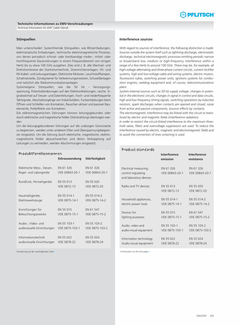
EMV/EMC · 205
Interference sources
With regard to sources of interference, the following distinction is made:Sources outside the system itself such as lightning discharge, electrostaticdischarge, technical electromagnetic processes emitting periodic narrowor broad-band low, medium or high-frequency interference within arange of a few Hertz to around 100 GHz. These may be, for example, allhigh-voltage alternating and three-phase current circuits, current rectifiersystems, high and low-voltage cable and wiring systems, electric motors,fluorescent tubes, switching power units, ignitions systems for combu-stion engines, welding equipment and, of course, telecommunicationsplant.System-internal sources such as 50 Hz supply voltage, changes in poten-tial in the electronic circuits, changes in signal in control and data circuits,high and low-frequency timing signals, switching operations by inductiveresistors, spark discharges when contacts are opened and closed, noisefrom active and passive components, bounce effects by contacts.The electromagnetic interference may be linked with the circuit or trans-fused by electric and magnetic fields (interference radiation).In order to restrict the circuit-linked interference to the maximum thres-hold value, filters and overvoltage suppressors are used. To reduce theinterference caused by electric, magnetic and electromagnetic fields andto avoid the connection of lines screening is used.
Interference Interference
emission resistance
Electrical measuring, EN 61 326 EN 61 326
control regulating VDE 00843-20-1 VDE 00843-20-1
and laboratory devices
Radio and TV devices EN 55 013 EN 55 020
VDE 0872-13 VDE 0872-20
Household appliances, EN 55 014-1 EN 55 014-2
electric power tools VDE 0875-14-1 VDE 0875-14-2
Devices for EN 55 015 EN 61 547
lighting purposes VDE 0875-15-1 VDE 0875-15-2
Audio, video and EN 55 103-1 EN 55 103-2
audio-visual equipment VDE 0875-103-1 VDE 0875-103-2
Information technology EN 55 022 EN 55 024
Audio-visual equipment VDE 0878-22 VDE 0878-24
Technische Informationen zu EMV-VerschraubungenTechnical Information for EMC Cable Glands
Störquellen
Man unterscheidet: Systemfremde Störquellen, wie Blitzentladungen,elektrostatische Entladungen, technische elektromagnetische Prozesse,von denen periodisch schmal- oder breitbandige nieder-, mittel- oderhochfrequente Dauerstörungen in einem Frequenzbereich von einigenHertz bis zu etwa 100 GHz ausgehen. Dies sind z. B. alle Wechsel- undDrehstromkreise der Starkstromtechnik, Stromrichteranlagen, HS- undNS-Kabel- und Leitungsanlagen, Elektrische Motoren, Leuchtstofflampen,Schaltnetzteile, Zündsysteme für Verbrennungsmotoren, Schweißanlagenund natürlich alle Telekommunikationsanlagen.Systemeigene Störquellen, wie die 50 Hz - Versorgungs-spannung, Potentialänderungen auf den Elektronikleitungen, rasche Si-gnalwechsel auf Steuer- und Datenleitungen, hoch- und niederfrequenteTaktsignale, Abschaltvorgänge von Induktivitäten, Funkentladungen beimÖffnen und Schließen von Kontakten, Rauschen aktiver und passiver Bau-elemente, Prelleffekte von Kontakten.Die elektromagnetischen Störungen können leitungsgebunden oderdurch elektrische und magnetische Felder (Störstrahlung) übertragen wer-den. Um die leitungsgebundenen Störungen auf die zulässigen Grenzwertezu begrenzen, werden unter anderem Filter und Überspannungsbegren-zer eingesetzt. Um die Störung durch elektrische, magnetische, elektro-magnetische Felder abzuschwächen und deren Verkopplung aufLeitungen zu vermeiden, werden Abschirmungen eingesetzt.
Störaussendung Störfestigkeit
Elektrische Mess-, Steuer-, EN 61 326 EN 61 326
Regel- und Laborgeräte VDE 00843-20-1 VDE 00843-20-1
Rundfunk, Fernsehgeräte EN 55 013 EN 55 020
VDE 0872-13 VDE 0872-20
Haushaltsgeräte, EN 55 014-1 EN 55 014-2
Elektrowerkzeuge VDE 0875-14-1 VDE 0875-14-2
Einrichtungen für EN 55 015 EN 61 547
Beleuchtungszwecke VDE 0875-15-1 VDE 0875-15-2
Audio-, Video- und EN 55 103-1 EN 55 103-2
audiovisuelle Einrichtungen VDE 0875-103-1 VDE 0875-103-2
Informationstechnik EN 55 022 EN 55 024
audiovisuelle Einrichtungen VDE 0878-22 VDE 0878-24
Fortsetzung auf der nachfolgenden Seite Continuation on the next page
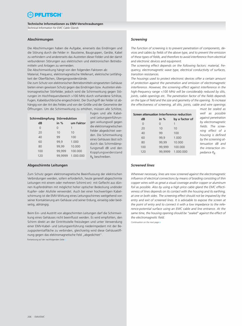
206 · EMV/EMC
Technische Informationen zu EMV-VerschraubungenTechnical Information for EMC Cable Glands
Abschirmungen
Die Abschirmungen haben die Aufgabe, einerseits das Eindringen unddie Störung durch die Felder in Bausteine, Baugruppen, Geräte, Kabelzu verhindern und andererseits das Austreten dieser Felder und der damitverbundenen Störungen aus elektrischen und elektronischen Betriebs-mitteln und Anlagen zu vermeiden.Die Abschirmwirkung hängt von den folgenden Faktoren ab:Material, Frequenz, elektromagnetische Wellenart, elektrische Leitfähig-keit der Oberflächen, Übergangswiderstände.Die zum Schutz von elektronischen Betriebsmitteln eingesetzten Gehäusebieten einen gewissen Schutz gegen das Eindringen bzw. Austreten elek-tromagnetischer Störfelder, jedoch wird die Schirmwirkung gegen Stö-rungen im Hochfrequenzbereich >100 MHz durch vorhandene Schlitze,Fugen, Kabeldurchbrüche eingeschränkt. Der Durchgriff der Felder ist ab-hängig von der Art des Feldes und von der Größe und der Geometrie derÖffnungen. Um die Schirmwirkung zu erhöhen, müssen alle Schlitze,
Fugen und alle Kabel-und Leitungseinführun-gen wirkungsvoll gegendie elektromagnetischenFelder abgedichtet wer-den. Die Schirmwirkungeines Gehäuses lässt sichdurch das Schirmdämp-fungsmaß dB und denKopplungswiderstandRk beschreiben.
Abgeschirmte Leitungen
Zum Schutz gegen elektromagnetische Beeinflussung der elektrischenVerbindungen werden, sofern erforderlich, heute generell abgeschirmteLeitungen mit einem oder mehreren Schirm(-en) mit Geflecht aus dün-nen Kupferdrähten mit möglichst hoher optischer Bedeckung und/oderKupfer- oder Alufolie verwendet. Auch bei einer hochwertigen Kabel-schirmung ist die EMV-Wirkung eines Leitungsschirmes weitgehend vonseiner Kontaktierung am Gehäuse und seiner Erdung, einseitig oder beid-seitig, abhängig.
Beim Ein- und Austritt von abgeschirmten Leitungen darf die Schirmwir-kung eines Gehäuses nicht beeinflusst werden. Es wird empfohlen, denSchirm direkt an der Eintrittsstelle freizulegen und unter Verwendungeiner EMV-Kabel- und Leitungseinführung niederimpedant mit der Be-zugspotentialfläche zu verbinden, gleichzeitig wird diese Gehäuseöff-nung gegen das elektromagnetische Feld „abgedichtet“.
Schirmdämpfung Störreduktion
dB in % um Faktor
0 0 1
20 10 10
40 99 100
60 99,9 1.000
80 99,99 10.000
100 99,999 100.000
120 99,9999 1.000.000
Screening
The function of screening is to prevent penetration of components, de-vices and cables by fields of the above type, and to prevent the emissionof these types of fields, and therefore to avoid interference from electricaland electronic devices and equipment.The screening effect depends on the following factors: material, fre-quency, electromagnetic wave type, electrical conductivity of surfaces,transition resistances.The housings used to protect electronic devices offer a certain amountof protection against the penetration and emission of electromagneticinterference. However, the screening effect against interference in thehigh-frequency range <100 MHz will be considerably reduced by slits,joints, cable openings etc. The penetration factor of the fields dependson the type of field and the size and geometry of the opening. To increasethe effectiveness of screening, all slits, joints, cable and wire openings
must be sealed aswell as possibleagainst penetrationby electromagneticfields. The scree-ning effect of ahousing is definedby the screening at-tenuation dB andthe interaction im-pedance Rk.
Screened lines
Wherever necessary, lines are now screened against the electromagneticinfluence of electrical connections by means of braiding consisting of thincopper wires with as great a visual coverage and/or copper or aluminumfoil as possible. Also by using a high price cable gland the EMC effecti-veness of lines depends on its contact with the housing and its earthing,at one or both sides. The screening effect should not be impaired by theentry and exit of screened lines. It is advisable to expose the screen atthe point of entry and to connect it with a low impedance to the refe-rence-potential surface using an EMC cable and line entrance. At thesame time, the housing opening should be "sealed" against the effect ofthe electromagnetic field.
Screen attenuation Interference reduction
dB in % by a factor of
0 0 1
20 10 10
40 99 100
60 99,9 1.000
80 99,99 10.000
100 99,999 100.000
120 99,9999 1.000.000
Fortsetzung auf der nachfolgenden Seite
Continuation on the next page
EMV/EMC · 207
EMC cable and line entries
The connection between the screening of the line and the housing musthave as low an ohmic and inductive resistance as possible. The technicalterm is low impedance. This is related to the frequency. This low transitionresistance is achieved by a 360° ring-shaped contacting of the cablescreen and by the short connection to the housing through the connec-ting thread.The EMC cable connection must provide as low an ohmic transition resi-stance as possible to the earthed housing wall under all environmentalconditions such as high temperature, humidity, dust etc.
Screen attenuation comparisonWe used a new measuring method. The cable glands are measured ex-clusively, i. e. without cable, precisely and reproducable independent fromthe environment. This can be done also in industrial field. The frequencyrange starts from DC up to 500 MHz with a measuring dynamic of mini-mum 100 dB and reproducability of < 1 dB. For frequencies below 1 MHzthe screen attenuation or transfer impedance is equal to the DC resistor.The curves shown in diagram page 171 are measured with a prototypeof the new measuring device.
EN 61000-6-1:2001 Electromagnetic compatibility (EMC)
VDE 0839-6-1 :2002-08 Generic standard – interference resistance,
household, commercial, trade and
industrial sectors.
EN 61000-6-2:2005 Electromagnetic compatibility (EMC)
VDE 0839-6-2 :2006-03 Generic standard – interference resistance
in industrial sector
EN 61000-6-3:2004 Electromagnetic compatibility (EMC)
VDE 0839-6-3 :2005-06 Generic standard – interference emissions,
household, commercial, trade and
industrial sectors
EN 61000-6-4:2001 Electromagnetic compatibility (EMC)
VDE 0839-6-4 :2002-08 Generic standard – interference emissions
in industrial sector
Technische Informationen zu EMV-VerschraubungenTechnical Information for EMC Cable Glands
EN 61000-6-1:2001 Elektromagnetische Verträglichkeit (EMV)
VDE 0839-6-1 :2002-08 Fachgrundnorm – Störfestigkeit
Wohnbereich, Geschäfts- und Gewerbe-
bereich sowie Kleinbetriebe
EN 61000-6-2:2005 Elektromagnetische Verträglichkeit (EMV)
VDE 0839-6-2 :2006-03 Fachgrundnorm – Störfestigkeit für
Industriebereich
EN 61000-6-3:2004 Elektromagnetische Verträglichkeit (EMV)
VDE 0839-6-3 :2005-06 Fachgrundnorm – Störaussendung für
Wohnbereich, Geschäfts- und Gewerbe-
bereich sowie Kleinbetriebe
EN 61000-6-4:2001 Elektromagnetische Verträglichkeit (EMV)
VDE 0839-6-4 :2002-08 Fachgrundnorm – Störaussendung für
Industriebereich
Fortsetzung auf der nachfolgenden Seite
Continuation on the next page
EMV-Kabel- und Leitungseinführungen
Die Verbindung von Leitungsschirm und Gehäuse muss einen möglichstniedrigen ohmschen und induktiven Widerstand haben, dieser ist fre-quenzabhängig. Der Fachbegriff lautet: niederimpedant. Durch eine ring-förmige 360°-Kontaktierung des Leitungsschirmes und durch die kurzeVerbindung zum Gehäuse über das Anschlussgewinde wird dieser nied-rige Übergangswiderstand erreicht.Die EMV-Kabelverschraubung muss bei allen Umwelteinflüssen wie Tem-peratur, Feuchtigkeit, Staub uvm. einen möglichst niederohmigen Über-gangswiderstand zur geerdeten Gehäusewand gewährleisten.
SchirmdämpfungsvergleichDas verwendete Meßverfahren ist neu. Es wird die Kabelverschraubungfür sich, das heißt ohne Kabel, präzise und gut reproduzierbar unabhän-gig von der Umgebung gemessen. Dies kann auch in industrieller Umge-bung geschehen. Der Frequenzbereich reicht von DC bis 500 MHz beieiner Meßdynamik von mindestens 100 dB und einer Reproduzierbarkeitvon < 1 dB. Bei Frequenzen unterhalb von 1 MHz entspricht die Schirm-dämpfung bzw. Transferimpendanz dem DC-Widerstand. Die im Diagramm auf Seite 171 dargestellten Kurven sind mit dem Pro-toptypen einer neuen Meßvorrichtung gemessen.
208 · EMV/EMC
Technische Informationen zu EMV-VerschraubungenTechnical Information for EMC Cable Glands
Definitionen und Begriffe der Elektromagnetischen Ver-träglichkeit (EU-Richtlinie 2004/108/EG und EMVG)
Anlage ist eine Zusammenschaltung von Apparaten, Systemen oderelektrischen oder elektronischen Bauteilen an einem gegebenen Ort der-art, dass diese Bestandteile miteinander eine bestimmte Aufgabe erfüllen;die Bestandteile müssen nicht als eine funktionelle oder kommerzielleEinheit in den Verkehr gebracht werden.
Apparat ist ein Endprodukt mit einer eigenständigen Funktion; er be-sitzt ein eigenes Gehäuse und gegebenenfalls für Endbenutzer gebräuch-liche Verbindungen.
Elektrische Störung ist jede elektromagnetische Erscheinung, die dieFunktion eines Gerätes beeinträchtigen könnte; eine elektromagnetischeStörung kann elektromagnetisches Rauschen, ein unerwünschtes Signaloder eine Veränderung des Ausbreitungsmediums selbst sein.
Elektromagnetische Verträglichkeit ist die Fähigkeit eines Gerä-tes, in der elektromagnetischen Umwelt zufriedenstellend zu arbeiten,ohne dabei selbst elektromagnetische Störungen zu verursachen, die fürandere in dieser Umwelt vorhandenen Geräte unannehmbar wären.
Geräte sind alle elektrischen und elektronischen Apparate, Systeme,Anlagen und Netze, die elektrische oder elektronische Bauteile enthalten.
Hersteller ist eine natürliche oder juristische Person oder rechtsfähigePersonengesellschaft, die für den Entwurf oder die Fertigung eines demGesetz unterliegenden Gerätes verantwortlich ist.
Inverkehrbringen ist das erstmalige entgeltliche oder unentgeltlicheBereitstellen eines unter die Richtlinie fallenden Gerätes im EWR zumZweck seines Vertriebes oder seines Betriebes im EWR.
Kopplungswiderstand ist das Verhältnis von induzierter Störspan-nung zwischen Innenleiter und Gehäuse zum aufgeprägten Störstromauf dem Schirm.
Netz ist eine Zusammenfassung von mehreren Übertragungsstrecken,die an einzelnen Punkten elektrisch oder optisch mittels einer Anlage,eines Systems, eines Apparates oder eines Bauteils verbunden sind.
Schirmdämpfung ist das logarithmische Verhältnis von elektroma-gnetischer Feldstärke außerhalb des Gehäuses zur elektromagnetischenFeldstärke innerhalb des Gehäuses.
Störfestigkeit ist die Fähigkeit eines Apparates, einer Anlage odereines Systems, während einer elektromagnetischen Störung ohne Funk-tionsbeeinträchtigung zu arbeiten.
System ist eine Kombination aus mehreren Apparaten oder gegebe-nenfalls elektrischen oder elektronischen Bauteilen, die vom selben Her-steller so entwickelt, hergestellt oder zusammengestellt wurden, dassdiese Bestandteile miteinander nach vorschriftsmäßiger Installierung mit-einander eine bestimmte Aufgabe erfüllen; ein System wird als eine funk-tionelle Einheit in Verkehr gebracht.
Zuständige Stelle ist die Stelle, die technische Berichte oder Beschei-nigungen über die Einhaltung der Schutzanforderungen anerkennt oderausstellt.
Terms and definitions concerning electromagnetic compa-tibility (EU directive 2004/108/EC and EMVG)
Plant: is an interconnection of equipment, systems or electrical or elec-tronic components in a certain location and in such a way that these con-stituent parts, acting together, fulfil a certain purpose. The constituentparts do not necessarily have to be released for use as a functional orcommercial unit.
Equipment: is an end product with an independent function. It has ahousing of its own and, if necessary, connections for use by the final user.
Electrical interference: any electromagnetic phenomenon whichmay negatively affect the function of a device. Electromagnetic interfe-rence may consist of noise, undesirable signals or a change in the diffu-sing medium itself.
Electromagnetic compatibility: is the ability of a device to functionsatisfactorily in its electromagnetic environment without itself causingelectromagnetic interference which may affect other devices in that en-vironment.
Devices: are all electrical and electronic equipment, systems, plant andnetworks containing electrical or electronic components.
Manufacturer: is a person or legal entity who or which is responsiblefor the design or manufacture of a device which is subject to the law.
Releasing for use: is the release for use for the first time (with or wit-hout payment) in the European Market of a device subject to the guide-lines for the purpose of its sale or use in the European Market.
Surface-transfer impedance: is the relation of induced interferencevoltage between the inner conductor and housing to the parasitic currentimprinted on the screen.
Network: is the interconnection of several transmission links which areconnected electrically or visually at certain points by means of a plant,system, equipment or component.
Screen attenuation: is the logarithmic relation between the strengthof the electromagnetic field outside the housing to that within the housing.
Resistance to interference: is the ability of plant, equipment or asystem to function without impairment during electromagnetic interfe-rence.
System: is a combination of equipment or electrical or electronic com-ponents, developed, manufactured or assembled by the same manufac-turer in such a way that these parts, following correct installation, jointlyfulfil a certain purpose. A system is released for use as a functional unit.
Responsible authority: is the authority which accepts or issues tech-nical reports or certificates regarding compliance with protective requi-rements.
Related Documents