eMMC FLASH Programming User’s Guide 1 ©1989-2019 Lauterbach GmbH eMMC FLASH Programming User’s Guide TRACE32 Online Help TRACE32 Directory TRACE32 Index TRACE32 Documents ...................................................................................................................... FLASH Programming .................................................................................................................... eMMC FLASH Programming User's Guide .............................................................................. 1 Introduction ............................................................................................................................. 3 How This Manual is Organized 3 Related Documents 3 Contacting Support 4 List of Abbreviations ............................................................................................................... 6 Background Knowledge ......................................................................................................... 7 What is an eMMC Flash Device? 7 About Blocks and Pages 7 About eMMC Interface Controllers in eMMC Flash Memories 8 Standard Approach ................................................................................................................. 9 Identifying and Running Scripts for eMMC Flash Programming 9 If There Is No Script 11 Scripts for eMMC Controllers ................................................................................................. 12 Establishing Communication between Debugger and Target CPU 13 Configuring the eMMC Controller 14 Resetting Default Values 15 Informing TRACE32 about the eMMC Controller Address 15 Informing TRACE32 about the eMMC Flash Programming Algorithm 15 Identifying the Correct Driver Binary File for an eMMC Flash Device 17 File Name Convention for eMMC Flash Drivers 17 Example for eMMC Controllers 18 FLASHFILE Declaration Examples 19 Declaration Example 1 19 Declaration Example 2 20 Checking the Identification from the eMMC Flash Device 21 Erasing the eMMC Flash Device 22 Programming the eMMC Flash Device 22 Copying the eMMC Flash Memory 23 Modifying the eMMC Flash Memory 25 Other Useful Commands 26

Welcome message from author
This document is posted to help you gain knowledge. Please leave a comment to let me know what you think about it! Share it to your friends and learn new things together.
Transcript
eMMC FLASH Programming User’s Guide
TRACE32 Online Help
TRACE32 Directory
TRACE32 Index
TRACE32 Documents ......................................................................................................................
FLASH Programming ....................................................................................................................
eMMC FLASH Programming User's Guide .............................................................................. 1
Introduction ............................................................................................................................. 3
How This Manual is Organized 3
Related Documents 3
Contacting Support 4
List of Abbreviations ............................................................................................................... 6
Background Knowledge ......................................................................................................... 7
What is an eMMC Flash Device? 7
About Blocks and Pages 7
About eMMC Interface Controllers in eMMC Flash Memories 8
Standard Approach ................................................................................................................. 9
Identifying and Running Scripts for eMMC Flash Programming 9
If There Is No Script 11
Scripts for eMMC Controllers ................................................................................................. 12
Establishing Communication between Debugger and Target CPU 13
Configuring the eMMC Controller 14
Resetting Default Values 15
Informing TRACE32 about the eMMC Controller Address 15
Informing TRACE32 about the eMMC Flash Programming Algorithm 15
Identifying the Correct Driver Binary File for an eMMC Flash Device 17
File Name Convention for eMMC Flash Drivers 17
Example for eMMC Controllers 18
FLASHFILE Declaration Examples 19
Declaration Example 1 19
Declaration Example 2 20
Checking the Identification from the eMMC Flash Device 21
Erasing the eMMC Flash Device 22
Programming the eMMC Flash Device 22
Copying the eMMC Flash Memory 23
Modifying the eMMC Flash Memory 25
Other Useful Commands 26
eMMC FLASH Programming User’s Guide 1 ©1989-2019 Lauterbach GmbH

Reading the eMMC Flash 26
Saving the eMMC Flash Device 27
Full Examples 28
Example 1 28
Example 2 30
FLASH Programming via Boundary Scan ............................................................................. 31
eMMC FLASH Programming User’s Guide 2 ©1989-2019 Lauterbach GmbH

eMMC FLASH Programming User’s Guide
Version 06-Nov-2019
Introduction
This manual describes the basic concept of eMMC Flash programming.
How This Manual is Organized
• About eMMC Interface Controllers in eMMC Flash Memories: Provides background information about the topic.
• Standard Approach: Describes the fastest way to get started with eMMC Flash programming. All you need to do is to identify and run the correct script.
Demo scripts for eMMC Flash programming are available in the folder:
~~/demo/<architecture>/flash/*.cmm
e.g. at91sam3u-emmc.cmm, omap3530-emmc.cmm, …
• New Scripts for eMMC Controllers: Describes how you can create a script if there is no demo script for the eMMC controller you are using.
Related Documents
A complete description of all eMMC Flash programming commands can be found in chapter “FLASHFILE” in “General Commands Reference Guide F” (general_ref_f.pdf).
The manual “List of Supported FLASH Devices” (flashlist.pdf) provides the following information:
• A list of the supported eMMC Flash memory devices.
• A list of the supported CPU families for the eMMC Flash protocol.
The Lauterbach home page provides an up-to-date list of
• Supported Flash devices under:http://www.lauterbach.com/ylist.html
• Supported eMMC Flash controllers under:http://www.lauterbach.com/ylistnand.html
eMMC FLASH Programming User’s Guide 3 ©1989-2019 Lauterbach GmbH
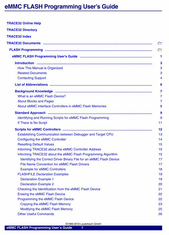
Contacting SupportLAUTERBACH GmbHAltlaufstrasse 4085635 Hoehenkirchen-SiegertsbrunnGermany
Be sure to include detailed system information about your TRACE32 configuration.
1. To generate a system information report, choose TRACE32 > Help > Support > Systeminfo.
2. Preferred: click Save to File, and send the system information as an attachment to your e-mail.
3. Click Save to Clipboard, and then paste the system information into your e-mail.
Phone (+49) 8102-9876-555
Fax (+49) 8102-9876-187
Internet http://www.lauterbach.com/tsupport.html or http://www.lauterbach.com/report.html Here you’ll find local and special support addresses.
E-mail [email protected] support address where your request will be answered within a short time if it is a basic support request or redirected to the appropriate address.
NOTE: Please help to speed up processing of your support request. By filling out the system information form completely and with correct data, you minimize the number of additional questions and clarification request e-mails we need to resolve your problem.
eMMC FLASH Programming User’s Guide 4 ©1989-2019 Lauterbach GmbH
NOTE: In case of missing script files (*.cmm), please proceed as requested in “If There is No Script”.
eMMC FLASH Programming User’s Guide 5 ©1989-2019 Lauterbach GmbH

List of Abbreviations
CS Chip selection
eMMC Embedded multimedia card
GPIO General purpose input/output
JEDEC Joint Electron Device Engineering Council
MISO Master input, slave output
MMC Multimedia card
MMCA MultiMediaCard Association
MOSI Master output, slave input
SCLK Serial clock
SDI Serial data input
SDO Serial data output
SPI Serial peripheral interface
SS Slave select
SSI Synchronous serial interface
eMMC FLASH Programming User’s Guide 6 ©1989-2019 Lauterbach GmbH

Background Knowledge
This chapter of the manual is aimed at users who are new to eMMC Flash programming; it does not address experts with many years of expertise in this area. This chapter gives you a brief overview of important terms in eMMC Flash programming, such as eMMC interface controller, sector, and block.
What is an eMMC Flash Device?
An eMMC Flash device is a non-volatile, rewritable mass storage device. It is used in consumer products such as mobile phones, PDAs, and digital cameras. Reasons why eMMC Flash devices have become widespread include:
• High data storage capacity
• Easy to integrate into the host system
• The eMMC standard developed by the MMCA and the JEDEC is an open, royalty-free standard.
About Blocks and Pages
Sector A sector has a size of 512 bytes, the same size as a sector in the FAT file system under DOS.
Block A page is the minimum size unit for writing and reading. The size is configurable (512, 1024, 2048 bytes), but normally the size is 512 bytes.
eMMC FLASH Programming User’s Guide 7 ©1989-2019 Lauterbach GmbH
About eMMC Interface Controllers in eMMC Flash Memories
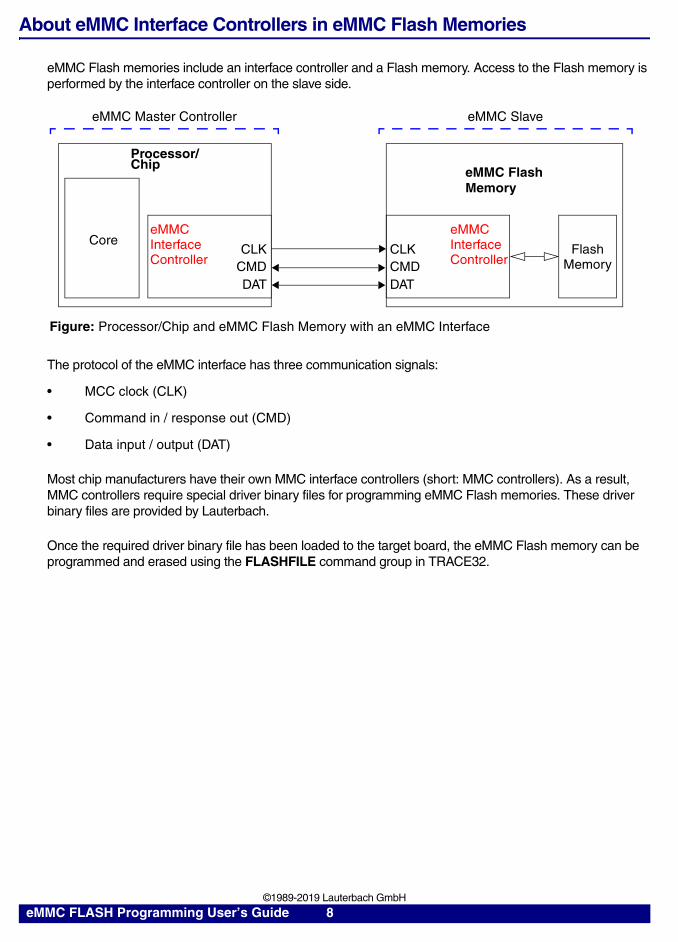
eMMC Flash memories include an interface controller and a Flash memory. Access to the Flash memory is performed by the interface controller on the slave side.
The protocol of the eMMC interface has three communication signals:
• MCC clock (CLK)
• Command in / response out (CMD)
• Data input / output (DAT)
Most chip manufacturers have their own MMC interface controllers (short: MMC controllers). As a result, MMC controllers require special driver binary files for programming eMMC Flash memories. These driver binary files are provided by Lauterbach.
Once the required driver binary file has been loaded to the target board, the eMMC Flash memory can be programmed and erased using the FLASHFILE command group in TRACE32.
eMMC Master Controller eMMC Slave
Processor/Chip
Figure: Processor/Chip and eMMC Flash Memory with an eMMC Interface
eMMC Core
eMMC Flash
CLKCMDDAT
ControllerInterface
CMDCLK
DAT
eMMC
ControllerInterface Flash
Memory
Memory
eMMC FLASH Programming User’s Guide 8 ©1989-2019 Lauterbach GmbH

Standard Approach
Standard Approach provides a compact description of the steps required to program eMMC Flash memories. This description is intentionally restricted to the standard use case.
For a detailed description of the eMMC Flash programming concepts, see “Scripts for eMMC Controllers” on page 12.
Identifying and Running Scripts for eMMC Flash Programming
Demo scripts (*.cmm) for eMMC Flash programming are provided by Lauterbach. They can be found in the TRACE32 installation directory. It contains scripts for programming eMMC Flash memories.
Path and file name convention of scripts to be used with eMMC controllers:
~~/demo/<architecture>/flash/<cpu_name>-<emmc_flash_code>.cmm Where ~~ is expanded to the <trace32_installation_directory>, which is c:/t32 by default.
To identify and run the required script:
1. Make a note of the <cpu_name> printed on the CPU; for example, dm365.
2. For information about supported Flash devices, access the Lauterbach website.
3. Click the + drill-down button next to Tool Chain, and then click Supported Flash Devices(http://www.lauterbach.com/ylist.html).
4. On the Supported Flash Devices page, select the required company from the drop-down list.
eMMC FLASH Programming User’s Guide 9 ©1989-2019 Lauterbach GmbH

5. Use the type printed on the Flash device to retrieve the <emmc_flash_code> from the web page.
For example, eMMC Flash type = NAND16GXH
Result: <emmc_flash_code> = emmc
6. Put the <cpu_name> and the <emmc_flash_code> together to form the script name:dm365-emmc.cmm
The script resides in this folder: ~~/demo/arm/flash/dm365-emmc.cmm
Where ~~ is expanded to the <trace32_installation_directory>, which is c:/t32 by default.
If the folder does not contain the script you are looking for, see “Scripts for eMMC Controllers” on page 12.
7. Run the script in TRACE32 by doing one of the following:
- Choose File > Run Script <cmm_script_name>
- In the command line, type DO <cmm_script_name>
Example
NOTE: Each script (*.cmm) includes a reference to the required eMMC Flash programming algorithm (*.bin).You do not need to program or select the algorithm.
; <code_range> <data_range> <file>FLASHFILE.TARGET 0x20000000++0x1FFF 0x20002000++0x1FFF
~~/demo/arm/flash/byte/emmc_at91sam.bin
eMMC FLASH Programming User’s Guide 10 ©1989-2019 Lauterbach GmbH

If There Is No Script
If there is no script for your device in this directory (~~/demo/<architecture>/flash/), then please send a request to [email protected] using the e-mail template below.
E-Mail Template:
Be sure to include detailed system information about your TRACE32 configuration. For information about how to create a system information report, see “Contacting Support”.
Normally we can provide support for a new device in two weeks.
If our support cannot provide you with a PRACTICE script, you will have to create your own PRACTICE script (*.cmm).
For more information, see “Scripts for eMMC Controllers” on page 12.
Chip name: ______________________
Name of serial Flash device: ________
Provide the CPU datasheet for us: ___________
Lend the target board to us by sending it to the address given in “Contacting Support”: ________
<system_information>
eMMC FLASH Programming User’s Guide 11 ©1989-2019 Lauterbach GmbH

Scripts for eMMC Controllers
This chapter describes how to create new scripts for eMMC Flash memories that are equipped with eMMC controllers.
The steps and the framework (see below) provide an overview of the process. They are described in detail in the following sections.
The following steps are necessary to create a new script:
1. Establish communication between debugger and target CPU.
2. Configure the eMMC controller.
3. Reset the eMMC Flash environment in TRACE32 to its default values.
4. Inform TRACE32 about the eMMC Flash register addresses (Flash declaration).
5. Inform TRACE32 about the eMMC Flash programming algorithm.
6. Check the identification from the eMMC Flash device.
7. Erase the eMMC Flash device.
8. Program the eMMC Flash device.
eMMC FLASH Programming User’s Guide 12 ©1989-2019 Lauterbach GmbH

The following framework can be used as base for eMMC Flash programming:
An ellipsis (…) in the framework indicates that command parameters have been omitted here for space economy.
Establishing Communication between Debugger and Target CPU
eMMC Flash programming with TRACE32 requires that the communication between the debugger and the target CPU is established. The following commands are available to set up this communication:
; Establish the communication ; between the target CPU and the; TRACE32 debugger.
; Configure the eMMC controller.
FLASHFILE.RESet ; Reset the eMMC Flash environment; in TRACE32 to its default values.
FLASHFILE.CONFIG … ; Specify the base address of the ; control register of the eMMC ; controller.
FLASHFILE.TARGET … ; Inform Trace 32 about:; - the FLASH programming algorithm; - the <code_address> and; the <data_address> for the; FLASH programming algorithm
FLASHFILE.Erase … ; Erase the eMMC Flash.
FLASHFILE.LOAD <main_file> … ; Program the file to eMMC Flash.
NOTE: The parametrization of FLASHFILE.CONFIG and FLASHFILE.TARGET requires expert knowledge.
SYStem.CPU <cpu> Specify your target CPU.
SYStem.Up Establish the communication between the debugger and the target CPU.
SYStem.CPU AT91SAM3U4 ; Select AT91SAM3U4 as the target CPU.
SYStem.Up ; Establish the communication between the; debugger and the target CPU.
eMMC FLASH Programming User’s Guide 13 ©1989-2019 Lauterbach GmbH
Configuring the eMMC Controller
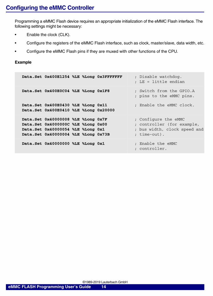
Programming a eMMC Flash device requires an appropriate initialization of the eMMC Flash interface. The following settings might be necessary:
• Enable the clock (CLK).
• Configure the registers of the eMMC Flash interface, such as clock, master/slave, data width, etc.
• Configure the eMMC Flash pins if they are muxed with other functions of the CPU.
Example
Data.Set 0x400E1254 %LE %Long 0x3FFFFFFF ; Disable watchdog.; LE = little endian
Data.Set 0x400E0C04 %LE %Long 0x1F8 ; Switch from the GPIO.A; pins to the eMMC pins.
Data.Set 0x400E0430 %LE %Long 0x11Data.Set 0x400E0410 %LE %Long 0x20000
; Enable the eMMC clock.
Data.Set 0x40000008 %LE %Long 0x7FData.Set 0x4000000C %LE %Long 0x00Data.Set 0x40000054 %LE %Long 0x1Data.Set 0x40000004 %LE %Long 0x73B
; Configure the eMMC; controller (for example,; bus width, clock speed and; time-out).
Data.Set 0x40000000 %LE %Long 0x1 ; Enable the eMMC; controller.
eMMC FLASH Programming User’s Guide 14 ©1989-2019 Lauterbach GmbH

Resetting Default Values
The following command is used to reset the eMMC Flash environment in TRACE32 to its default values.
Informing TRACE32 about the eMMC Controller Address
The following command is used to inform TRACE32 about the base address of the eMMC controller.
For information about the base address, refer to the manufacturer’s data sheet.
Example
Informing TRACE32 about the eMMC Flash Programming Algorithm
The following command is available to inform TRACE32 about the eMMC Flash programming algorithm:
Parameters
• <code_range>
Define an address range in the target´s RAM to which the eMMC Flash programming algorithm is loaded.
FLASHFILE.RESet Reset the eMMC Flash environment in TRACE32 to its default values.
FLASHFILE.CONFIG <mmc_controller_base_address> , , , represents don’t-care parameters.
; Base address of the eMMC controller in the AT91SAM3UFLASHFILE.CONFIG 0x40000000 , ,
FLASHFILE.TARGET <code_range> <data_range> <file> Specify the eMMC Flash programming driver and where it runs in the target RAM.
eMMC FLASH Programming User’s Guide 15 ©1989-2019 Lauterbach GmbH

Required size for the code is: size_of(<file>) + 32 byte
• <data_range>
Define the address range in the target´s RAM where the programming data is buffered for the programming algorithm.
The argument buffer used for the communication between the TRACE32 software and the programming algorithm is located at the first 64 bytes of <data_range>. The 256 byte stack is located at the end of <data_range>.
<buffer_size> = size_of(<data_range>) - 64 byte argument buffer - 256 byte stack
<buffer_size> is the maximum number of bytes that are transferred from the TRACE32 software to the eMMC Flash programming algorithm in one call.
• <file>
Lauterbach provides ready-to-run driver binary files for eMMC Flash programming. They are located in the TRACE32 installation directory:
~~/demo/<architecture>/flash/byte
Where ~~ is expanded to the TRACE32 installation directory, which is c:/t32 by default.
For detailed information about how to determine the <file> parameter, see “Identifying the Correct Driver Binary File for an eMMC Flash Device” on page 17.
FLASH algorithm
Figure: Memory mapping for the <code_range>
32 byte
64 byte argument buffer
Figure: Memory mapping for the <data_range>
buffer for programming data
256 byte stack
eMMC FLASH Programming User’s Guide 16 ©1989-2019 Lauterbach GmbH
Identifying the Correct Driver Binary File for an eMMC Flash Device
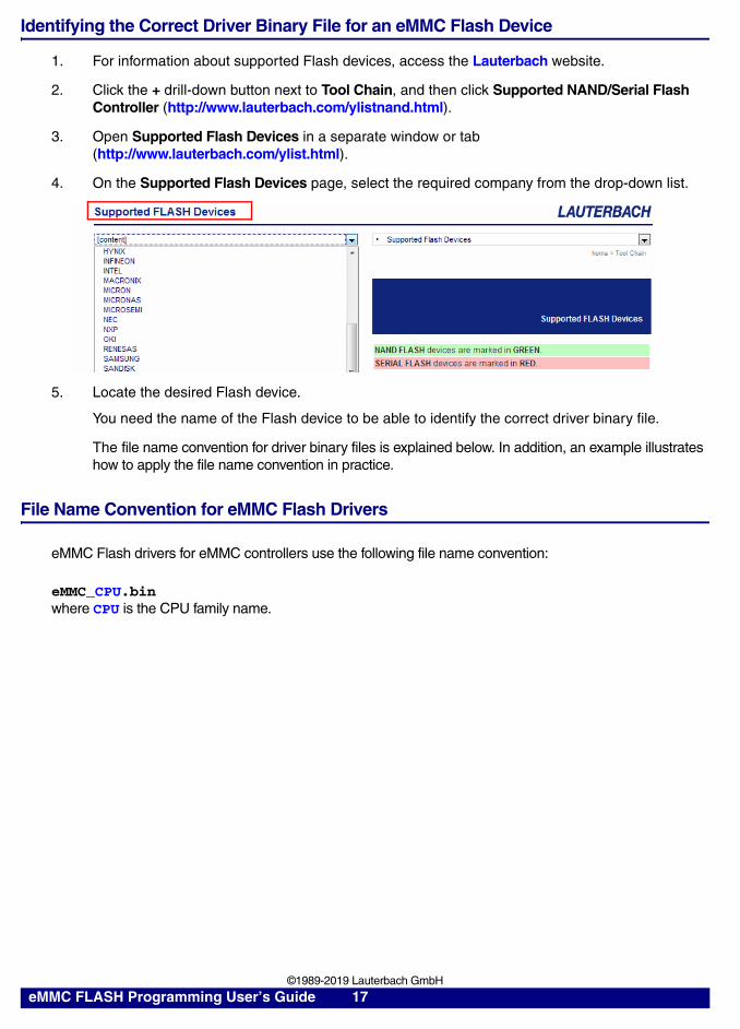
1. For information about supported Flash devices, access the Lauterbach website.
2. Click the + drill-down button next to Tool Chain, and then click Supported NAND/Serial Flash Controller (http://www.lauterbach.com/ylistnand.html).
3. Open Supported Flash Devices in a separate window or tab(http://www.lauterbach.com/ylist.html).
4. On the Supported Flash Devices page, select the required company from the drop-down list.
5. Locate the desired Flash device.
You need the name of the Flash device to be able to identify the correct driver binary file.
The file name convention for driver binary files is explained below. In addition, an example illustrates how to apply the file name convention in practice.
File Name Convention for eMMC Flash Drivers
eMMC Flash drivers for eMMC controllers use the following file name convention:
eMMC_CPU.bin where CPU is the CPU family name.
eMMC FLASH Programming User’s Guide 17 ©1989-2019 Lauterbach GmbH

Example for eMMC Controllers
Target:
• CPU OMAP3530 with the eMMC controller omap3530
• eMMC Flash device NAND16GXH
Taken together, the Code column and the Controller column make up the file name of the eMMC Flash driver binary file: eMMC_omap.bin.
The binary file resides in this folder: ~~/demo/arm/flash/byte
Where ~~ is expanded to the TRACE32 installation directory, which is c:/t32 by default.
This results in the following command line:
; Specify the eMMC Flash programming algorithm and where it runs in ; the target RAM. <code_range> <data_range> <file>FLASHFILE.TARGET 0x4020000++0x1FFF 0x4022000++0x1FFF
~~/demo/arm/flash/byte/emmc_omap.bin
eMMC FLASH Programming User’s Guide 18 ©1989-2019 Lauterbach GmbH

FLASHFILE Declaration Examples
Declaration Example 1
CPU: OMAP4430 (Texas Instruments)
Base address of the eMMC controller:
0x480B4000
Driver file: ~~/demo/arm/flash/byte/emmc_omap.bin Where ~~ is expanded to the TRACE32 installation directory, which is c:/t32 by default.
…
; Reset the FLASHFILE declaration within TRACE32.FLASHFILE.RESet
; Base address of the eMMC controller in the OMAP4430FLASHFILE.CONFIG 0x480B4000 , ,
; Specify the eMMC Flash programming algorithm and where it runs on; the target RAM. <code_range> <data_range> <file>FLASHFILE.TARGET 0x40301000++0x1FFF 0x40303000++0x2FFF
~~/demo/arm/flash/byte/emmc_omap.bin
…
eMMC FLASH Programming User’s Guide 19 ©1989-2019 Lauterbach GmbH

Declaration Example 2
CPU: AT91SAM3U4 (ATMEL)
Base address of the eMMC controller:
0x40000000
Driver file: ~~/demo/arm/flash/byte/emmc_at91sam.bin Where ~~ is expanded to the TRACE32 installation directory, which is c:/t32 by default.
…
; Reset the FLASHFILE declaration within TRACE32.FLASHFILE.RESet
; Base address of the eMMC controller in the AT91SAM3U4FLASHFILE.CONFIG 0x40000000 , ,
; Specify the eMMC Flash programming algorithm and where it runs on; the target RAM. <code_range> <data_range> <file>FLASHFILE.TARGET 0x20000000++0x1FFF 0x20002000++0x1FFF
~~/demo/arm/flash/byte/emmc_at91sam.bin
…
eMMC FLASH Programming User’s Guide 20 ©1989-2019 Lauterbach GmbH

Checking the Identification from the eMMC Flash Device
The following command can be used to check if TRACE32 can access the eMMC Flash device:
FLASHFILE.GETID Get the ID values of the eMMC Flash device.
; Open the TRACE32 AREA window.AREA.view
; Check the access to the eMMC Flash device; by getting the manufacturer ID and the device ID.FLASHFILE.GETID
eMMC FLASH Programming User’s Guide 21 ©1989-2019 Lauterbach GmbH

Erasing the eMMC Flash Device
The following command is available to erase eMMC Flash devices:
Example:
Programming the eMMC Flash Device
The following commands are available to program the eMMC Flash:
The data from <file> is written to the address range specified by <range>. If no <range> or <address> is specified, programming starts at address 0x0.
Example 1:
Example 2:
FLASHFILE.Erase <range> Erase a specified range of the eMMC Flash device.
; Erase 2MB starting at 0x0.FLASHFILE.Erase 0x0--0x1FFFFF
FLASHFILE.LOAD <file> [<address> | <range>] Program the eMMC Flash.
FLASHFILE.LOAD <file> [<address> | <range>] /ComPare Verify the contents of the file against the eMMC Flash.
; Program the contents of my_file.bin to the eMMC Flash memory starting; at address 0x0.FLASHFILE.LOAD my_file.bin 0x0
; Verify the contents of my_file.bin against the eMMC Flash memory; starting at address 0x0.FLASHFILE.LOAD my_file.bin 0x0 /ComPare
eMMC FLASH Programming User’s Guide 22 ©1989-2019 Lauterbach GmbH

Copying the eMMC Flash Memory
The following command is available to copy:
• Any data from any CPU memory area to the eMMC Flash memory, or
• Any data from one address range of the eMMC Flash to another address range within the same eMMC Flash memory; for example, for backup purposes.
Example 1:
Result (1):
Example 2:
FLASHFILE.COPY <source range> <target addr> Copy data from the source range to the defined address of the eMMC Flash.
FLASHFILE.COPY <source range> <target addr> /ComPare Verify the source range data against the target range data.
; Copy the 1MB virtual memory data at 0x0 to the eMMC Flash address ; at 0x100000.; VM: The virtual memory of the TRACE32 software.FLASHFILE.COPY VM:0x0--0xFFFFF 0x100000
; Verify the data between virtual memory and eMMC Flash.FLASHFILE.COPY VM:0x0--0xFFFFF 0x100000 /ComPare
Data is copied from theCPU to the eMMC Flash
eMMC FLASH Programming User’s Guide 23 ©1989-2019 Lauterbach GmbH
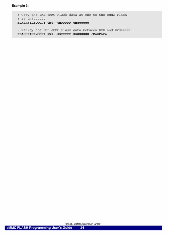
Example 3:
; Copy the 1MB eMMC Flash data at 0x0 to the eMMC Flash ; at 0x800000.FLASHFILE.COPY 0x0--0xFFFFF 0x800000
; Verify the 1MB eMMC Flash data between 0x0 and 0x800000.FLASHFILE.COPY 0x0--0xFFFFF 0x800000 /ComPare
eMMC FLASH Programming User’s Guide 24 ©1989-2019 Lauterbach GmbH

Modifying the eMMC Flash Memory
The following command is available to modify the contents of the eMMC Flash memory.
Example 1:
Example 2:
FLASHFILE.Set [<address> | <range>] %<format> <data> Modify the contents of the eMMC Flash.
; Write 4 bytes of data 0x12345678 to the address 0x100000.; LE = little endianFLASHFILE.Set 0x100000 %LE %Long 0x12345678
; Write data 0x0 from 0x100000 to 0x13FFFF in the eMMC Flash.FLASHFILE.Set 0x100000++0x13FFFF %Long 0x0
Result (1)
eMMC FLASH Programming User’s Guide 25 ©1989-2019 Lauterbach GmbH

Other Useful Commands
The CPU cannot read eMMC Flash memories directly. But TRACE32 provides special commands for reading eMMC Flash memories. The contents of the eMMC Flash are displayed in a window.
Reading the eMMC Flash
The following command allows to read the eMMC Flash memory.
Example:
FLASHFILE.DUMP [<address>] [/<format>] Display a hex-dump of the eMMC Flash.
; Display a hex-dump of the eMMC Flash starting at 0x1000.; Display the information in 2-bit format (/Long option).FLASHFILE.DUMP 0x1000 /Long
Result
eMMC FLASH Programming User’s Guide 26 ©1989-2019 Lauterbach GmbH
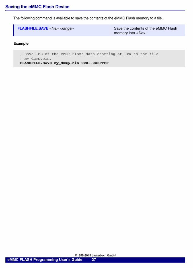
Saving the eMMC Flash Device
The following command is available to save the contents of the eMMC Flash memory to a file.
Example:
FLASHFILE.SAVE <file> <range> Save the contents of the eMMC Flash memory into <file>.
; Save 1MB of the eMMC Flash data starting at 0x0 to the file; my_dump.bin. FLASHFILE.SAVE my_dump.bin 0x0--0xFFFFF
eMMC FLASH Programming User’s Guide 27 ©1989-2019 Lauterbach GmbH

Full Examples
Example 1
CPU: OMAP4430
eMMC Flash: SanDisk, iNAND 8 GBytes
Internal SRAM: 0x40301000
SD/MMC Controller Register: 0x480B4000 (MMCHS2)
SYStem.RESet
system.CPU omap4430
SYStem.JtagClock 10.Mhz
SYStem.Option DACR ON ; Give debugger global write permissions.
SETUP.IMASKASM OFF ; Lock interrupts while single stepping.
SYSTEM.MEMACCESS DAP ; Enable DAP access.
TrOnchip.set DABORT OFF
TrOnchip.set PABORT OFF
TrOnchip.Set UNDEF OFF
SYStem.mode.attach
wait 1.s
if run()
break
GOSUB disable_watchdog
D.S NSD:0x480B422C %LE %Long 0xe0f87 ; Configure the eMMC clock. ; LE = little endian
BREAK.RESet
FLASHFILE.RESet
; Base address of the eMMC controller in the OMAP4430 FLASHFILE.CONFIG 0x480B4000 , ,
eMMC FLASH Programming User’s Guide 28 ©1989-2019 Lauterbach GmbH

; Specify the eMMC Flash programming algorithm and where it runs in; the target RAM. <code_range> <data_range> <file> FLASHFILE.TARGET 0x40301000++0x1FFF 0x40303000++0x1FFF
~~/demo/arm/flash/byte/emmc_omap.bin
; Check the access to the eMMC Flash device; by getting the manufacturer ID and the device ID. FLASHFILE.GETID
DIALOG.YESNO “Program flash memory?”
ENTRY &progflash
IF &progflash
(; Erase Flash.
FLASHFILE.ERASE 0x0--0xFFFFFF
; Write Flash. FLASHFILE.LOAD * 0x0
; Verify Flash. FLASHFILE.LOAD * 0x0 /ComPare
)
; Display a hex-dump of the eMMC Flash starting at 0x0. FLASHFILE.DUMP 0x0
ENDDO
eMMC FLASH Programming User’s Guide 29 ©1989-2019 Lauterbach GmbH

Example 2
CPU: DM365
eMMC Flash: Numonyx, NAND16GXH is connected to the MMC0 controller.
SDRAM: 0x80002000
eMMC Controller Register: 0x01D11000
SYStem.DownSYStem.JtagClock 1Mhz
SYStem.RESetSYStem.CPU DM365SYStem.o.rb offSYStem.JtagClock 1MhzSYStem.mode gowait 1.sif run()break
; Enable for the eMMC.Data.Set 0x1C48018 %Long 0x4000000 ; Enable for MMC0 controller
; Configure eMMC CLK.Data.Set 0x01D11004 %Long 0x0117 ; MMC CLKData.Set 0x01D11000 %Long 0x0007 ; MMC_CTL Data.Set 0x01D11000 %Long 0x0000 ; MMC_CTL
FLASHFILE.RESet Break.RESet
; Base address of the eMMC controller in the DM365. FLASHFILE.CONFIG 0x01D11000 , ,
; Specify the eMMC Flash programming algorithm and where it runs in; the target RAM. <code_range> <data_range> <file> FLASHFILE.TARGET 0x80002000++0x1FFF 0x80004000++0x1FFF
~~/demo/arm/flash/byte/emmc_dm365.bin
; Check the access to the eMMC Flash device; by getting the manufacturer ID and the device ID. FLASHFILE.GETID
DIALOG.YESNO “Program flash memory?” ENTRY &progflash IF &progflash
(; Erase FLASH.
FLASHFILE.ERASE 0x0--0xFFFFFF
eMMC FLASH Programming User’s Guide 30 ©1989-2019 Lauterbach GmbH
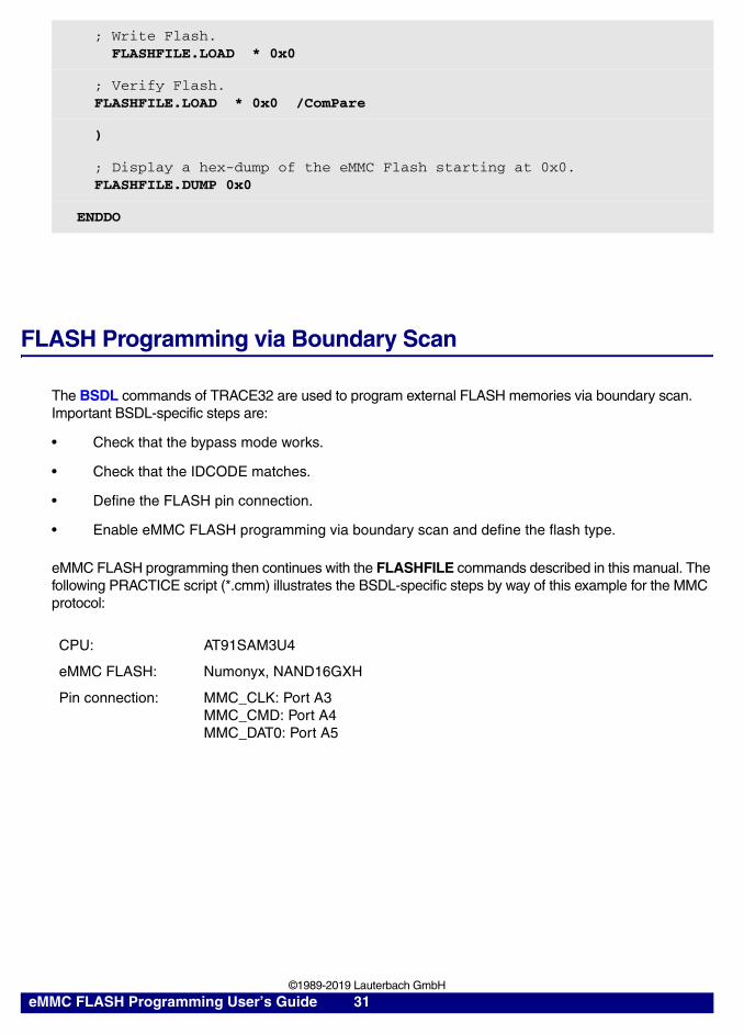
FLASH Programming via Boundary Scan
The BSDL commands of TRACE32 are used to program external FLASH memories via boundary scan. Important BSDL-specific steps are:
• Check that the bypass mode works.
• Check that the IDCODE matches.
• Define the FLASH pin connection.
• Enable eMMC FLASH programming via boundary scan and define the flash type.
eMMC FLASH programming then continues with the FLASHFILE commands described in this manual. The following PRACTICE script (*.cmm) illustrates the BSDL-specific steps by way of this example for the MMC protocol:
; Write Flash. FLASHFILE.LOAD * 0x0
; Verify Flash. FLASHFILE.LOAD * 0x0 /ComPare
)
; Display a hex-dump of the eMMC Flash starting at 0x0. FLASHFILE.DUMP 0x0
ENDDO
CPU: AT91SAM3U4
eMMC FLASH: Numonyx, NAND16GXH
Pin connection: MMC_CLK: Port A3MMC_CMD: Port A4MMC_DAT0: Port A5
eMMC FLASH Programming User’s Guide 31 ©1989-2019 Lauterbach GmbH
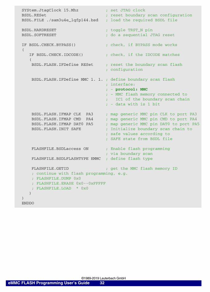
SYStem.JtagClock 15.Mhz ; set JTAG clockBSDL.RESet ; reset boundary scan configurationBSDL.FILE ./sam3u4e_lqfp144.bsd ; load the required BSDL file
BSDL.HARDRESET ; toggle TRST_N pinBSDL.SOFTRESET ; do a sequential JTAG reset
IF BSDL.CHECK.BYPASS() ; check, if BYPASS mode works( IF BSDL.CHECK.IDCODE() ; check, if the IDCODE matches ( BSDL.FLASH.IFDefine RESet ; reset the boundary scan flash ; configuration
BSDL.FLASH.IFDefine MMC 1. 1. ; define boundary scan flash ; interface: ; - protocol: MMC ; - MMC flash memory connected to ; IC1 of the boundary scan chain ; - data with is 1 bit
BSDL.FLASH.IFMAP CLK PA3 ; map generic MMC pin CLK to port PA3 BSDL.FLASH.IFMAP CMD PA4 ; map generic MMC pin CMD to port PA4 BSDL.FLASH.IFMAP DAT0 PA5 ; map generic MMC pin DAT0 to port PA5 BSDL.FLASH.INIT SAFE ; Initialize boundary scan chain to ; safe values according to ; SAFE state from BSDL file
FLASHFILE.BSDLaccess ON ; Enable flash programming ; via boundary scan FLASHFILE.BSDLFLASHTYPE EMMC ; define flash type
FLASHFILE.GETID ; get the MMC flash memory ID ; continue with flash programming, e.g. ; FLASHFILE.DUMP 0x0 ; FLASHFILE.ERASE 0x0--0xFFFFF ; FLASHFILE.LOAD * 0x0 ))ENDDO
eMMC FLASH Programming User’s Guide 32 ©1989-2019 Lauterbach GmbH
Related Documents